Instrukcja obsługi Yaesu VX-8GR
Przeczytaj poniżej 📖 instrukcję obsługi w języku polskim dla Yaesu VX-8GR (168 stron) w kategorii radio. Ta instrukcja była pomocna dla 13 osób i została oceniona przez 2 użytkowników na średnio 4.5 gwiazdek
Strona 1/168

144/430 MHz
DUAL BAND FM TRANSCEIVER
WITH GPS
OPERATING MANUAL
VX-8GR/GE
VERTEX STANDARD CO., LTD.
4-8-8 Nakameguro, Meguro-Ku, Tokyo 153-8644, Japan
VERTEX STANDARD U.S.A. Inc.
6125 Phyllis Drive, Cypress, California 90630, U.S.A.
YAESU UK LTD.
Unit 12, Sun Valley Business Park, Winnall Close
Winchester, Hampshire, SO23 0LB, U.K.
VERTEX STANDARD HK LTD.
Unit 1306-1308, 13F., Millennium City 2, 378 Kwun Tong Road,
Kwun Tong, Kowloon, Hong Kong
VERTEX STANDARD (AUSTRALIA) PTY., LTD.
Tally Ho Business Park, 10 Wesley Court, East Burwood, VIC, 3151

Contents
Scanning ..................................................................................... 54
General ................................................................................... 54
VFO Scanning ........................................................................ 56
How to Skip (Omit) a Frequency during VFO Scan ........ 57
Memory Scanning .................................................................. 58
How to Skip (Omit) a Channel during Memory Scan ...... 59
Preferential Memory Scan ................................................ 59
Memory Bank Scan .......................................................... 61
Programmable (Band Limit) Memory Scan (PMS) ............... 62
“Priority Channel” Scanning (Dual Watch) ........................... 63
Priority Revert Mode ....................................................... 64
Automatic Lamp Illumination on Scan Stop .......................... 65
Band Edge Beeper ................................................................. 65
GPS Operation .......................................................................... 66
Setting the Time Zone (Time Offset) ..................................... 67
Selecting the Display Units of the GPS Screen ...................... 68
Selecting the Map Datum ...................................................... 68
APRS® Operation ...................................................................... 70
Preparations ........................................................................... 70
Receiving an APRS Beacon ................................................... 73
Transmit an APRS Beacon .................................................... 76
Receiving an APRS Message ................................................. 79
Transmit an APRS Message .................................................. 81
ARTSTM (Automatic Range Transponder System) ................ 83
Basic ARTSTM
Setup and Operation ..................................... 84
ARTSTM Polling Time Options .............................................. 84
ARTSTM Alert Beep Options ................................................. 85
CW Identifier Setup ............................................................... 86
Spectrum Analyzer Operation ................................................. 87
Smart Search Operation ........................................................... 88
Message Feature ........................................................................ 90
General ................................................................................... 90
Programming a Message ........................................................ 90
Programming a Member List ................................................. 91
Set your Personal ID .............................................................. 92
Sending a Message ................................................................. 93
Receiving a Message .............................................................. 94
Emergency Feature ................................................................... 95
Emergency Channel Operation .............................................. 95
Emergency Automatic ID (EAI) feature ................................ 96
Selecting the EAI mode and its Transmit Time ................ 97
Activating the EAI feature ............................................... 97
To Locate an Unresponsive Operator
using the EAI feature ............ 98
Internet Connection Feature .................................................... 99
General ................................................................................... 99
SRG (“Sister Radio Group”) Mode ....................................... 99
FRG (“Friendly Radio Group”) Mode ................................. 100
DTMF Operation ..................................................................... 102
CW Learning Feature ............................................................. 104
CW Training Feature .............................................................. 106
Sensor Mode ............................................................................. 107
Clock Set ............................................................................. 107
Miscellaneous Setting .............................................................. 108
Password .............................................................................. 108
Programming the d Key .................................................. 110
ATT (Front End Attenuator) ............................................... 111
Receive Battery Saver Setup ............................................... 112
TX Battery Saver ................................................................. 112
Disabling the BUSY Indicator ............................................. 113
Automatic Power-Off (APO Feature) .................................. 113
Transmitter Time-Out Timer (TOT) .................................... 114
ON/OFF Preset Timer .......................................................... 115
Busy Channel Lock-Out (BCLO) ........................................ 116
Changing the TX Deviation Level ....................................... 116
Changing the Microphone Gain ........................................... 117
S-and TX Power Meter Symbols ......................................... 117
Display Contrast .................................................................. 118
Display Dimmer ................................................................... 118
My Bands Operation ............................................................ 119
Changing the Status of the g Key .................................... 120
Reset Procedures ..................................................................... 121
Cloning ..................................................................................... 122
Set Mode ................................................................................... 124
APRS/GPS Set Mode .............................................................. 148
Specifications ........................................................................... 160
Appendix (Computer Connections) ....................................... 162
FCC Notice ............................................................................... 164
Introduction ................................................................................. 1
Controls &Connections ............................................................... 2
Display Icons & Indicators ......................................................... 3
Keypad Functions ....................................................................... 4
Accessories & Option .................................................................. 6
Accessories Supplied with the VX-8GR .................................. 6
Available Options for your VX-8GR ....................................... 7
Installation of Accessories ........................................................... 8
Antenna Installation ................................................................. 8
Belt Clip Installation ................................................................ 8
Installation of FNB-101LI Battery Pack .................................. 9
Battery Life Information ........................................................ 10
Installation of FBA-39 Alkaline Battery Case ....................... 11
Interface of Packet TNCs .......................................................... 12
Operation ................................................................................... 13
Switching Power On and Off ................................................. 13
Adjusting the Volume Level .................................................. 13
Squelch Adjustment ............................................................... 14
Selecting the Operating Band ................................................ 15
Selecting the Frequency Band ................................................ 16
Frequency Navigation ............................................................ 17
Sub Band Operation ......................................................... 17
1) Tuning Dial .................................................................. 17
2) Direct Keypad Frequency Entry .................................. 17
3) Scanning ....................................................................... 18
Transmission .......................................................................... 19
Changing the Transmitter Power Level ............................ 19
Advanced Operation ................................................................. 21
Keyboard Locking ................................................................. 21
Adjusting the Keypad Beeper Volume Level ......................... 22
Setting the Frequency Display Image Size ............................. 22
Audio Muting ......................................................................... 23
Keypad/LCD Illumination ...................................................... 23
Changing the Channel Steps .................................................. 24
Changing the Receiving Mode ............................................... 24
SQL S-meter .......................................................................... 25
Repeater Operation ................................................................... 26
General ................................................................................... 26
Repeater Shifts ....................................................................... 26
Automatic Repeater Shift (ARS) ........................................... 26
Manual Repeater Shift Activation .......................................... 27
Changing the Default Repeater Shifts .............................. 27
Tone Calling (1750 Hz) ......................................................... 28
Checking the Repeater Uplink (Input) Frequency ................. 28
CTCSS/DCS/EPCS Operation ................................................. 29
CTCSS Operation .................................................................. 29
DCS Operation ...................................................................... 30
DCS Code Inversion ........................................................ 32
Tone Search Scanning ........................................................... 34
EPCS (Enhanced Paging & Code Squelch) ........................... 35
Storing the CTCSS Tone Pairs for EPCS Operation ....... 35
Activating the Enhanced Paging & Code Squelch System .. 36
Paging Answer Back ........................................................ 36
CTCSS/DCS/EPCS Bell Operation ....................................... 37
Programming the User Melody ........................................ 38
Split Tone Operation .............................................................. 39
CTCSS/DCS/EPCS Vibrator Operation ................................ 40
Memory Mode (Regular Memory Channel Operation) ......... 42
Memory Storage .................................................................... 43
Storing Independent Transmit Frequency (“Odd Splits”) ... 44
Memory Recall ....................................................................... 44
HOME Channel Memory ....................................................... 45
Labeling Memories ................................................................ 46
Memory Offset Tuning .......................................................... 47
Masking Memories ................................................................ 48
Memory Bank Operation ....................................................... 49
Assigning Memories to a Memory Bank .......................... 49
Memory Bank Recall ........................................................ 49
Removing Memories from a Memory Bank ..................... 50
Changing a Memory Bank’s Name .................................. 50
Moving Memory Data to the VFO ........................................ 51
Memory Only Mode ............................................................... 51
Memory Mode (Special Memory Channel Operation) .......... 52
Weather Broadcast Channels ................................................. 52
VHF Marine Memory Channels ............................................. 53

VX-8GR/GE OPERATING MANUAL 1
The Ultra Compact VX-8GR/GE (2.4”W x 3.7”H x 1.1”D) is equipped with a GPS receiver and
thinner than the previous advanced model - It is packed with advanced technology and fea-
tures, designed for outdoor operation. It is submersible (IPX5) and shockproof! The compact
case combines a rugged die-cast chassis with the clean, tough polycarbonate resin front panel.
Its shockproof versatility will allow you to operate the radio in the toughest environments.
The large High-resolution Dot Matrix LCD display provides clear, easy-to-read indication of
both “A” (Main band) and “B” (Sub band) frequencies, the operating mode, and S-meters for
both bands. When you engage the Spectrum Scope function, the high-resolution display will
indicate relative signal strengths of up to ±50 adjacent channels!
The built-in worldwide standard AX.25 Data TNC Modem permits uncomplicated APRS
®
operation. (Automatic Packet/Position Reporting System: APRS
® is a registered trademark of
the APRS Software and Bob Bruninga, WB4APR.) The VX-8GR/GE supports APRS
® 1200/
9600 bps data communication on the “B” (Sub band) band only. You may communicate your
location to other APRS
® stations along with the position, speed and heading displayed on your
radio! You and others will be able to see your APRS
® movement on the web! The VX-8GR/
GE displays the received station’s positions, heading directions, messages, distances, icons (43
kinds), weather information, object, etc. With the list function you may automatically store and
recall up to 30 messages and the APRS
® data from up to 50 stations. The built-in GPS Receiver
Unit provides you with real time APRS
® data.
Enhanced Paging and Code Squelch (EPCS) allow you to page a particular station and only
receive calls from that station. A security Password may be set, which will allow you to turn on
and operate the transceiver only after you enter the Password. A convenient key provides ac-
cess to Vertex Standard’s WIRES
™ (Wide-Coverage Internet Repeater Enhancement System).
The Emergency Automatic ID (EAI) function can automatically cause your VX-8GR/GE to
transmit your callsign and engage your rig’s microphone, even if you are disabled and unable
to press the PTT switch. Additional features include: transmit Time-Out Timer (TOT), Auto-
matic Power-Off (APO), and Automatic Repeater Shift (ARS). Yaesu’s exclusive ARTS
™
(Auto-Range Transponder System) which “beeps” the user when you move out of communica-
tions range with another ARTS
™ equipped station. There is provision to reduce the TX devia-
tion for use in areas of high channel congestion. The squelch circuit allows adjusting the squelch
to open at a programmable setting of the S-Meter, thus reducing guesswork in setting the
squelch threshold. Provides a DATA jack which enables the display of location data (Lat/Lon)
from an after-market GPS receiver, and outputs the location data (Lat/Lon) of the built-in GPS
receiver unit and the Waypoint data of the received APRS beacons.
We appreciate your purchase of the VX-8GR/GE, and encourage you to read this manual
thoroughly, and learn about the many exciting features of your thrilling new Yaesu hand-held
transceiver!
INTRODUCTION

VX-8GR/GE OPERATING MANUAL2
CONTROLS & CONNECTIONS
ANTENNA Jack
Connect the sup-
plied rubber flex an-
tenna (or another
antenna presenting
a 50-Ohm imped-
ance) here.
VOL Key
Rotate the D I A L
knob while pressing
and holding this key
to adjust the audio
volume level.
DIAL Knob
The main tuning Dial
is used to set the op-
erating frequency,
and is also used for
audio volume level,
menu selections,
and other adjust-
ments.
MIC/SP Jack
This four conductor
miniature jack allows
connection of an op-
t i o n al M H - 3 4 B 4 B
Sp e a k e r M i c r o -
phone, M H- 37A 4 B
Ear pi ece /M icro-
phon e, or V C- 2 5
VOX Headset.
EXT DC Jack
This coaxial DC jack
allows connection to
a n e x t e r n a l D C
power source (7.4-
12V DC). The center
pin of this jack is the
Positive (+) line.
MIC
The internal micro-
phone is located
here.
LED Light
This white LED will
glow (or flash) during
“Emergency Chan-
nel” operation. It can
also be useful as a
flash light in a dark
environment via the
Set Mode Item 45
LED LIGHT.
PTT Switch
(“Push To Talk”)
Press this switch in-
ward to transmit, and
release it (to receive)
after your transmis-
sion is completed.
MONI/T.CALL Key
USA version:
Pressing this key
disables the noise
squelching action,
allowing you to hear
very weak signals
near the background
noise level.
European version:
Pressing this key
activates the T.CALL
(1750 Hz) for re-
peater access.
p(PWR) Switch
Press and hold this
switch for 2 seconds
t o t o g g l e t h e
transceiver’s power
“on” and “off”.
Press this switch
br i e f l y wh i le the
transceiver is turned
“on” to toggle the key
lockout feature “on”
or “off”.
DATA Jack
This three conductor
2.5-mm jack pro-
vides connection
points for an Exter-
nal computer.
KEYPAD
The 18 front panel
key buttons select
many of the most im-
portant operating
features.
The functions of the
keys are described
in detail on pages 4
and 5.
F/W Key
Pressing this key
activates the “Alter-
nate” key functions
of the keypad.
SPEAKER
The internal speaker
is located here.
GPS RECEIVER
The internal GPS re-
ceive r is located
hear.
TX/BUSY Lamps
These indi cators
glow green when a
signal is being re-
ceived and red when
transmitting.

VX-8GR/GE OPERATING MANUAL 3
DISPLAY NDICATORS ICONS & I
FREQUENCY CONTROL
VFO: VFO Mode
MR: Memory Mode
TUN: Memory Tune Mode
HOM: Home Channel Memory
PMS: Programmable Memory Scan Mode
VDW: Dual Watch Active
(VFO-Memory Channel)
MDW:Dual Watch Active
(Memory Channel-Memory Channel)
SMS: Smart Search Active
Note: When these icons blink, the Sub Band Operation features are active.
SQUELCH TYPE & RADIO MODE
TN: Tone Encoder Active
TSQ: Tone Squelch Active
DCS: Digital Code Squelch Active
RTN: Reverse Tone Squelch Active
PR: User Programmed Reverse CTCSS Decoder Active
PAG: Enhanced Paging & Code Squelch (EPCS) Active
MSG: Message Feature Active
DC: Split Tone Feature Active (DCS Encode only)
T-D: Split Tone Feature Active (Encodes a CTCSS Tone and Decodes a DCS Code)
D-T: Split Tone Feature Active (Encodes a DCS Code and Decodes a CTCSS Tone)
A12: APRS® Feature Active (1200 bps)
A96: APRS® Feature Active (9600 bps)
MISCELLANEOUS SETTING
: Repeater Shift Direction (Minus Shift)
: Repeater Shift Direction (Plus Shift)
: Independent Transmit Frequencies
(Odd Splits)
: Attenuator Active
: Bell Alarm Active
OPERATING MODE
NFM: FM
AM: AM
Note 1): When a bar is shown under these icons, the Vibrator function is active.
2): When a dashed bar is shown under these icons, the CTCSS/DCS/EPCS Vibrator function is active.
3): When a short-dashed bar is shown under these icons, the APRS Message Vibrator function is active.
VOLUME LEVEL
TX POWER LEVEL
HI: High Power (5 W)
L3: LOW3 Power (2.5 W)
L2: LOW2 Power (1 W)
L1: LOW1 Power (0.02 W)
OPERATING FREQUENCY
S&PO METER
ICON
: Secondary Keypad Active
: Internet Connection Feature (WiRESTM ) Active
: DTMF Autodialer Active
: Emergency Automatic ID (EAI) Feature Active
: Automatic Power-Off Active
: Key Lock Active
: Mute Feature Active
: Battery Saver Active
: Battery Indicator
“B” Band
Display
Icon
“A” Band
Display

VX-8GR/GE OPERATING MANUAL4
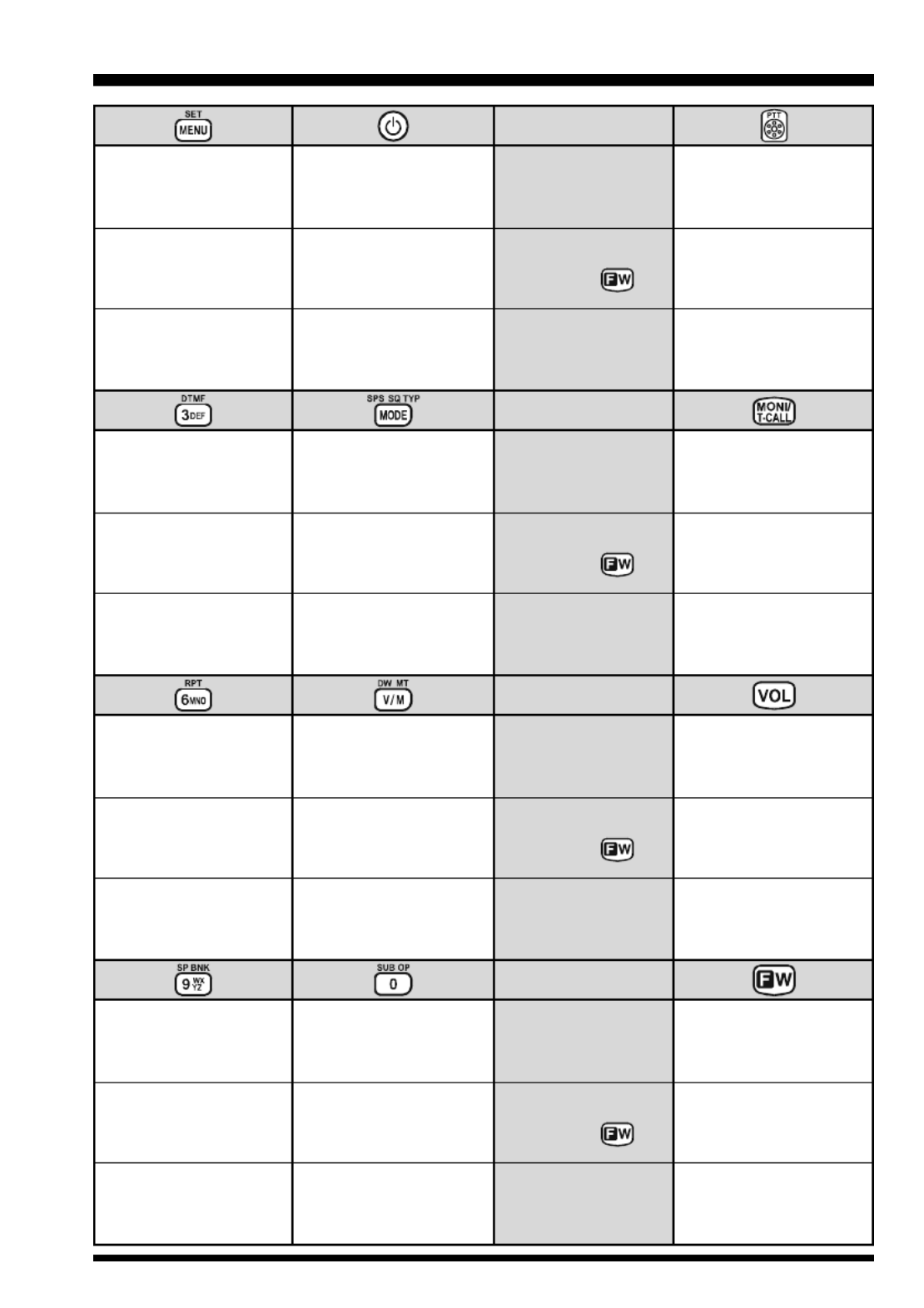
KEYPAD FUNCTIONS
Frequency entry digit “1”
Switches the “Upper”
frequency to be the
“Operating” (TX) Band.
Activates the
Dual Receive Feature.
Switches the “Lower”
frequency to be the
“Operating” (TX) Band.
Activates the
Dual Receive Feature.
PRIMARY FUNCTION
(PRESS KEY)
(1) Moves operation to the
next-highest frequency band.
(2) Activates the Memory Bank
feature.
Moves operation to the
next-lowest frequency band
T FHIRD UNCTION
(P RESS AND H KOLD EY)
(1) Select the Bandwidth for
the VFO scanner.
(2) Select the Memory Scan
mode.
Selects the synthesizer steps
to be used during VFO
operation.
Frequency entry digit “2”
SECONDARY FUNCTION
(P + RESS )
PRIMARY FUNCTION
(PRESS KEY)
T FHIRD UNCTION
(P RESS AND H KOLD EY)
Selects the CTCSS Tone,
DCS code, EPCS code, or
Message.
SECONDARY FUNCTION
(P + RESS )
PRIMARY FUNCTION
(PRESS KEY)
T FHIRD UNCTION
(P RESS AND H KOLD EY)
SECONDARY FUNCTION
(P + RESS )
PRIMARY FUNCTION
(PRESS KEY)
T FHIRD UNCTION
(P RESS AND H KOLD EY)
Frequency entry digit “4”
Activates the ARTS feature.
Reverses transmit and
receive frequencies while
working through a repeater.
Switches operation to the
“Home” (favorite frequency)
channel.
Activates the EMERGENCY
function.
Frequency entry digit “5”
Activates the Memory Scan
“Skip” channel selection
mode.
Activates the Internet
Connection feature.
Selects the desired transmit
power output level.
No Action.
Frequency entry digit “7”
Activates the Audio Mute
Feature.
Frequency entry digit “8”
Activates the Spectrum
Analyzer (Spectra-ScopeTM)
feature.
No Action No Action
No Action No Action
No Action No Action
No Action No Action
NOTE
Press the a or b
key to switch the fre-
quency display between
the “Double-size Charac-
ter” and “Small Character”
mode while in Mono band
operation.
SECONDARY FUNCTION
(P + RESS )
VX-8GR/GE OPERATING MANUAL 5
KEYPAD FUNCTIONS
Enter the Set Mode.
Activate the APRS
(Automatic Position
Reporting System) function.
No Action
Frequency entry digit “3”
Selects the DTMF mode. SECONDARY FUNCTION
(P + RESS )
PRIMARY FUNCTION
(PRESS KEY)
T FHIRD UNCTION
(P RESS AND H KOLD EY)
SECONDARY FUNCTION
(P + RESS )
PRIMARY FUNCTION
(PRESS KEY)
T FHIRD UNCTION
(P RESS AND H KOLD EY)
Selects the receive mode
between AM and FM.
Engage the Special
Search mode.
Activates the CTCSS
or DCS operation.
SECONDARY FUNCTION
(P + RESS )
PRIMARY FUNCTION
(PRESS KEY)
T FHIRD UNCTION
(P RESS AND H KOLD EY)
SECONDARY FUNCTION
(P + RESS )
PRIMARY FUNCTION
(PRESS KEY)
T FHIRD UNCTION
(P RESS AND H KOLD EY)
Frequency entry digit “6”
Selects the direction of the
uplink frequency shift (either
“–”, “+”, or “simplex”) during
repeater operation.
Switches frequency control
between the VFO and
Memory System.
Activates the “Memory Tune”
mode while in the Memory
Recall mode.
Activates the Priority (Dual
Watch) function.
Frequency entry digit “9”
Enters the “Special Memory”
mode.
Frequency entry digit “0”
Activates the Sub Band
Operation feature.
USA Version: Disables the Noise and
Tone Squelch System.
European Version: Activates the
T.CALL (1750 Hz) for repeater access.
No Action
Activates the “Secondary”
key function.
Disables the “Secondary”
key function.
Toggle the DIAL knob
function between the
“Frequency Control” and
“Receiver Audio Control”.
Rotate the DIAL knob while
holding this key to adjust the
audio volume level.
No Action
No Action
No Action No Action
Activates the “Memory Write”
mode (for memory channel
storage).
USA Version: Disables the Noise and
Tone Squelch System.
European Version: Activates the
T.CALL (1750 Hz) for repeater access.
Toggle the transceiver’s
power “on” and “off”.
No Action
Activates the transmitter.
Activates the transmitter
temporarily in “high” power,
while the transceiver is in
“low” power operation.
Activates the Transmitter.
USA Version: Adjusts the Squelch
threshold leve.
European Version: Activates the
T.CALL (1750 Hz) with “high” power.

VX-8GR/GE OPERATING MANUAL6
A S CCESSORIES UPPLIED WITH THE VX-8GR
Antenna 1 pc YHA-72 (Q3000236)
Li-Ion Battery Pack 1 pc FNB-101LI (7.4V/1,100mAh: AAG10X001)
Battery Charger 1 pc NC-86B (120 VAC, Type-A plug: Q9500149),
PA-44C (230 VAC, Type-C plug: Q9500165) or
PA-44U (230 VAC, Type-BF plug: Q9500166)
Belt Clip 1 pc (RA1053600)
Screws 2 pcs (M3x10SUS: U24310020)
Plastic Cap 1 pc (RA1054200)
Sheet 1 pcs (RA1231300)
Operating Manual 1 pc
Warranty Card 1 pc
ACCESSORIES & OPTIONS

VX-8GR/GE OPERATING MANUAL 7
AVAILABLE OPTIONS FOR YOUR VX-8GR
CSC-95 Soft Case
FBA-39 3 x “AA” Cell Battery Case (batteries not supplied)
FNB-101LI Li-Ion Battery Pack (7.4V/1,100 mAh)
FNB-102LI Li-Ion Battery Pack (7.4V/1,800 mAh)
CD-41 Rapid Charger (requires NC-86B/C/U or PA-44B/C/U)
NC-86BBattery Charger for the CD-41 (for USA/EXP market)
PA-44B/C/UBattery Charger for the CD-41 (for European market)
E-DC-5B DC Cable w/Noise Filter (USA/EXP market only)
E-DC-6 DC Cable; plug and wire only (USA/EXP market only)
CN-3 BNC-to-SMA Adapter
MH-34B4B Speaker/Microphone
MH-37A4B Ear peace Microphone
CT-44 Microphone Adapter
CT-144 Clone Cable
CT-143 PC Connection Cable
: “B” suffix is for use with 120 VAC (Type-A plug), “C” suffix is for use with 230 VAC
(Type-C plug), and “U” suffix is for use with 230 VAC (Type-BF plug).
Availability of accessories may vary. Some accessories are supplied as standard per local
requirements, while others may be unavailable in some regions. Consult your Yaesu Dealer
for details regarding these and any newly-available options. Connection of any non-Yaesu
approved accessory, should it cause damage, may void the Limited Warranty on this ap-
paratus.
ACCESSORIES & OPTIONS
: USA/EXP market only

VX-8GR/GE OPERATING MANUAL8
Figure 1
Figure 2
ANTENNA INSTALLATION
The supplied antenna provides good results over the entire frequency range of the trans-
ceiver. However, for enhanced base station medium-wave and shortwave reception, you
may wish to connect an external (outside) antenna.
TO INSTALL THE SUPPLIED ANTENNA
Hold the bottom end of the antenna, then screw it onto the mating connec-
tor on the transceiver until it is snug. Do not over-tighten by use of ex-
treme force.
Notes:
Never transmit without having an antenna connected.
Carefully turn the supplied antenna onto the SMA jack. Never twist
the upper part of the antenna while screwing it onto the mating con-
nector of the transceiver.
If using an external antenna for transmission, ensure that the SWR
presented to the transceiver is 1.5:1 or lower.
INSTALLATION OF ACCESSORIES
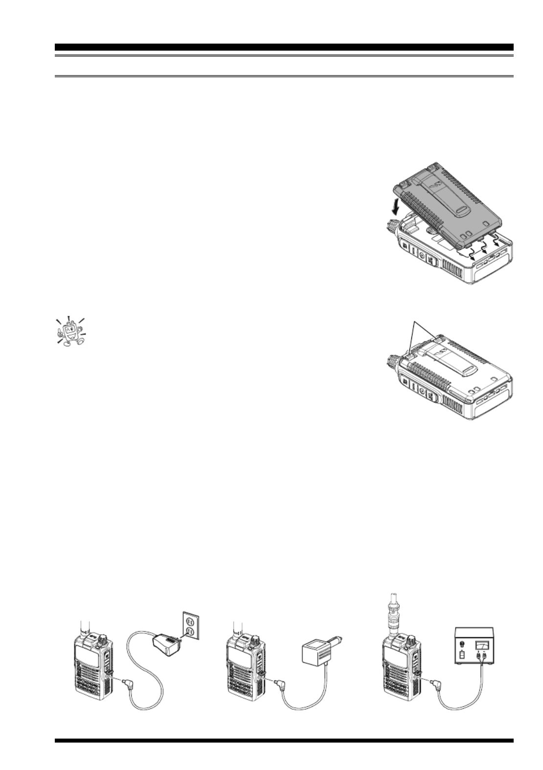
BELT CLIP INSTALLATION
Install the supplied Belt Clip to the FNB-101LI
Battery Pack using the supplied two screws
(Figure 1). Use only the screws included with
the Belt Clip to mount the Belt Clip to the back
of the Battery Pack!
If you do not need the Belt Clip, install the sup-
plied Plastic Cap to the Battery Pack (Figure
2). If you install the belt clip later, push the Plas-
tic Cap out with a small tool or screwdriver.
VX-8GR/GE OPERATING MANUAL 9
INSTALLATION OF FNB-101LI BATTERY PACK
The FNB-101LI is a high-performance Lithium-Ion battery providing high capacity in a
very compact package. Under normal use, the FNB-101LI may be used for approxi-
mately 300 charge cycles, after which operating time may be expected to decrease. An old
battery pack, which is displaying diminished capacity should be replaced with a new one.
To install the FNB-101LI Battery Pack, carefully mate the
battery’s three alignment tabs with their corresponding align-
ment slots on the transceiver bottom case, then gently press
the top side of the Battery Pack until it locks in place with a
“click”.
To remove the Battery Pack, turn the transceiver off and
remove any protective cases. Press the Battery Pack Re-
lease Knobs downward to unlock the latch, then remove
the Battery Pack from the transceiver.
1) The VX-8GR/GE battery must be correctly installed,
to maintain the waterproof integrity.
2) Always use the Vertex Standard Co., Ltd. Model FNB-101LI
or FNB-102LI Lithium-Ion Battery Pack.
3) Battery Pack shall not be exposed to excessive heat such as
sunshine, fire, or the like.
4) Risk of explosion if battery is replaced by an incorrect type.
Dispose of used batteries according to the instructions
If the battery has never been used, or its charge is depleted, it may be charged by connect-
ing the NC-86/PA-44 Battery Charger, as shown in the illustration, to the EXT DC jack.
In the USA market, if only 12 ~ 16 Volt DC power is available, the optional E-DC-5B DC
Adapter (with its cigarette lighter plug) or E-DC-6 DC Cable may also be used for charg-
ing the battery, as shown in the illustration.
INSTALLATION OF ACCESSORIES
INSTALL
REMOVE
BATTERY PACK RELEASE KNOB
E-DC-5B
(USA MARKET ONLY)
NC-86/PA-44 E-DC-6
(USA MARKET ONLY)

VX-8GR/GE OPERATING MANUAL10
INSTALLATION OF ACCESSORIES
While the battery is being charged, the display will indicate “CHARGING” and the “A”
indicator will glow red. The S-meter will deflect according to the charging status. When
charging is finished, the display will change to indicate “COMPLETE” and the “A” indica-
tor will glow green.
1) Turn the radio off while charging the battery.
2) Perform the battery charging where the ambient temperature range +41
°F to +95 °F (+5 °C to +35 °C). Charge out of this range could cause damage
to the battery pack.
3) Use only the Vertex Standard Co., Ltd. Model NC-86B (for USA market) or PA-44C/
U (for European market)Battery Charger.
BATTERY LIFE INFORMATION
When the battery charge is almost depleted, a “Low Voltage” indicator will appear on the
display. When this icon appears, it is recommended that you charge the battery soon.
TX 6 seconds, RX 6 seconds, and Squelched 48 seconds (continuous operating cycle).
GPS receiver is “off”.
The present battery voltage can be displayed manually on the LCD, by following the
instructions on page 107.
Battery capacity may be reduced during extremely cold weather. Keeping the radio inside
your parka may help preserve the full charge capacity.
OPERATING BAND
144 MHz
430 MHz
FNB-101LI
5.0 hours
5.0 hours
FBA-39
17 hours
16 hours
BATTERY INDICATOR
: Full battery power
: Enough battery power
: Low battery power
: Poor battery power
(w/Blink): Charge (or replace) the battery
B ATTERY LIFE (A .PPROX )
FNB-102LI
8.5 hours
8.0 hours
INSTALLATION OF FNB-101LI BATTERY PACK
VX-8GR/GE OPERATING MANUAL 11
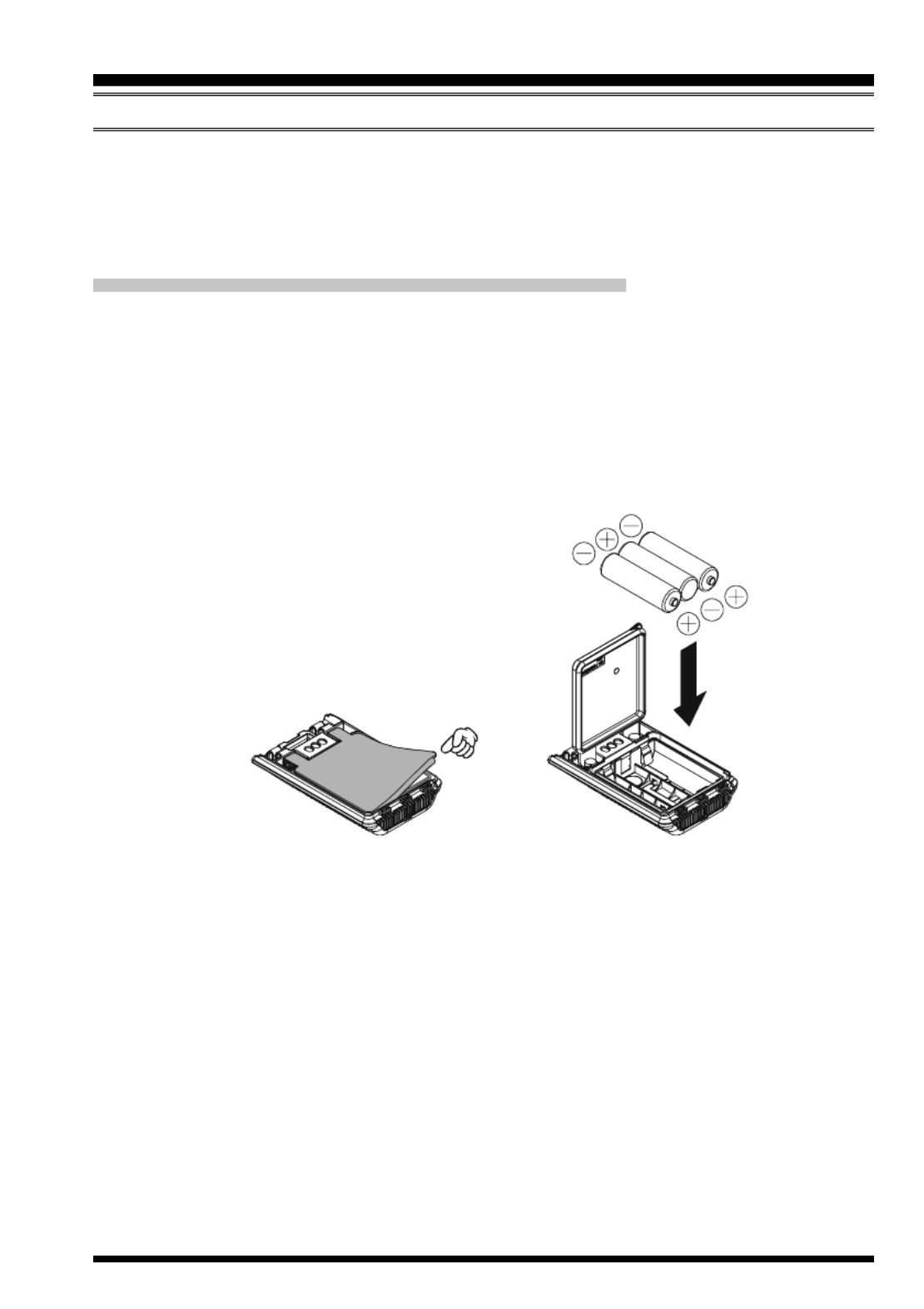
INSTALLATION OF FBA-39 ALKALINE BATTERY CASE (OPTION)
The optional FBA-39 Battery Case allows receive monitoring using three “AA” size Al-
kaline batteries. Alkaline batteries can also be used for low power transmission in an
emergency. The power output level selections will be limited to: 1 W/50 mW (for 144/430
MHz FM).
TO INSTALL ALKALINE BATTERIES INTO THE FBA-39
1. Lift up the lower right corner of the rubber cover, and then open the cover (Figure 1).
2. Referring to Figure 2, slide the batteries into the FBA-39 as shown in the illustration,
with the Negative [–] side of the batteries touching the spring connections inside the
FBA-39.
3. Close the rubber cover.
4. Install the FBA-39 in the transceiver in the same manner as the FNB-101LI.
INSTALLATION OF ACCESSORIES
The FBA-39 does not provide connections for charging, since Alkaline cells cannot be
re-charged. Therefore, the NC-86B, PA-44C/U E-DC-5B, , or E-DC-6 may safely be
connected to the EXT DC jack when the FBA-39 is installed (E-DC-5B and E-DC-6 are
usable only in a USA market).
Notes:
The FBA-39 is designed for use only with AA-type Alkaline cells.
If you do not use the VX-8GR/GE for a long time, remove the Alkaline batteries from
the FBA-39, as battery leakage could cause damage to the FBA-39 and/or the trans-
ceiver.
Figure 1 Figure 2
VX-8GR/GE OPERATING MANUAL12
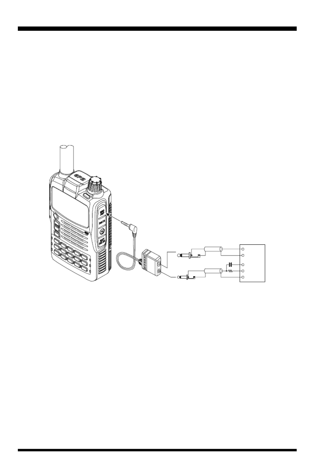
INTERFACE OF PACKET TNCS
The VX-8GR/GE may be used for Packet operation, using the optional CT-44 Micro-
phone Adapter (available from your Yaesu dealer) for easy interconnection to commonly-
available connectors wired to your TNC.
The audio level from the receiver to the TNC may be adjusted by rotating the DIAL knob
while pressing and holding the g key, as with voice operation. The input level to the
VX-8GR/GE from the TNC should be adjusted at the TNC side; the optimum input volt-
age is approximately 5 mV at 2000 Ohms.
Be sure to turn the transceiver and TNC off before connecting the cables, to prevent volt-
age spikes from damaging your transceiver.
TNC
SP
GND
GND
2 k
Ω
10 Fµ
MIC
MIC
EAR
PTT
CT-44 Microphone Adapter
MIC/SP Jack

VX-8GR/GE OPERATING MANUAL 13
Hi! I’m R. F. Radio, and I’ll be helping you along as you learn the many
features of the VX-8GR/GE. I know you’re anxious to get on the air, but I
encourage you to read the “Operation” section of this manual as thoroughly
as possible, so you’ll get the most out of this fantastic new transceiver. Now. . .let’s get
operating!
S WITCHING POWER ON AND OFF
1. Be sure the battery pack is installed, and that it is fully charged. Connect the antenna
to the top panel ANTENNA jack.
2. Press and hold in the p(PWR) switch (on the left side
of the front panel) for 2 seconds. Two beeps will be heard
when the switch has been held long enough. The open-
ing message will appear briefly on the display, then the
frequency display will appear. After another two sec-
onds, the receive-mode Battery Saver function will be-
come active, unless you have disabled it (see page 112).
3. To turn the VX-8GR/GE off, press and hold in the p
(PWR) switch again for 2
seconds.
If you don’t hear the two “Beep” tones when the radio comes on, the Beeper
may have been disabled via the Menu system. See page 22, which tells you
how to reactivate the Beeper.
A VDJUSTING THE OLUME LEVEL
Rotate the DIAL knob while pressing and holding the g
key to set the desired audio level. Clockwise rotation in-
creases the volume level.
1) The Volume level may be set on the
“A-Band” and “B-Band” separately.
2) While adjusting the Audio volume level, the
“SP VOLUME” notation appears in the S- & PO meter
area.
3) Pressing the f key followed by the g key, the DIAL knob function changes to the
Volume Level adjustment instead of the frequency control. In this case, the “Volume
Level Indicator” on the display blinks. Pressing the f key followed by the g key
again, returns the DIAL knob function to the frequency control. You may also change
the g key function via Set Mode Item 99: VOLUME MODE. See page 120 for details.
OPERATION

VX-8GR/GE OPERATING MANUAL14
OPERATION
SQUELCH ADJUSTMENT
The VX-8GR/GE’s Squelch system allows you to mute the background noise when no
signal is being received. Not only does the Squelch system make “standby” operation
more pleasant, it also significantly reduces battery current consumption.
1. On the VX-8GR, press the f key, then press the e
key on the left side of the radio. This provides a “Short-
cut” to Set Mode Item 85: SQL LEVEL.
On the VX-8GE, press and hold the m key for one
second to enter the Set Mode, rotate the DIAL knob to
select Set Mode Item 85: SQL LEVEL., then press the
m key briefly to enable selection of this Menu Item.
2. Now, rotate the DIAL knob to the point where the back-
ground noise is just silenced (typically at a setting of about
“3” or “4” on the scale); this is the point of maximum sen-
sitivity to weak signals.
3. When you are satisfied with the Squelch threshold setting, press the PTT key briefly
to save the new setting and exit to normal operation.
4. You may also adjust the Squelch setting by using the “Set” (Menu) mode. See page
143 for details.
1) The Squelch level may be set on the “Main” and “Sub” bands separately.
2) If you’re operating in an area of high RF pollution, you may need to
consider “Tone Squelch” operation using the built-in CTCSS Decoder. This
feature will keep your radio quiet until a call is received from a station sending a carrier
which contains a matching (sub audible) CTCSS tone. Or if your friends have radios
equipped with DCS (Digital Coded Squelch) like your VX-8GR/GE, try using that mode
for silent monitoring of busy channels.
24-HOUR CLOCK
The VX-8GR/GE has a 24-hour clock with a calendar which covers all dates from
January 1, 2000 through December 31, 2099. Set the clock according to the “Clock
Set” column on page 107.
VX-8GR/GE OPERATING MANUAL 15
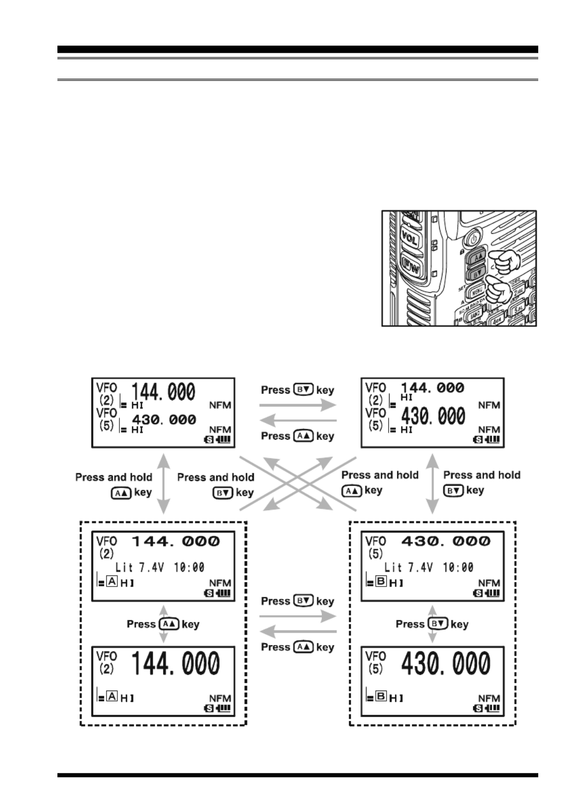
S ELECTING THE OPERATING BAND
In the factory default configuration, the VX-8GR/GE operates in the “Dual Receive”
mode.
During Dual Receive operation, the “A-Band” frequency will be displayed on the upper
part of the LCD, and the “B-Band” frequency will be displayed on the lower part. The
“Operating” band (the band on which transmission and band/frequency changes are pos-
sible) is shown in large characters, and “Receive only” band is shown in small characters.
Press the a key briefly to engage the “A-Band” fre-
quency as the “Operating” band. Alternatively, press the
b key briefly to engage the “B-Band” frequency, as de-
scribed previously.
Press and hold in the a or b key for 1/2 seconds to
switch to Mono Band Operation. During Mono band op-
eration, you may change the display between “double-size
character” and “large character” by pressing the a b/ key.
OPERATION
VX-8GR/GE OPERATING MANUAL 17
FREQUENCY NAVIGATION
The VX-8GR/GE will initially be operating in the “VFO” mode, as just described. This is a
frequency step system which allows free tuning throughout the currently-selected operating
band.
Three basic frequency navigation methods are available on the VX-8GR/GE:
1) TUNING DIAL
Rotation of the DIAL knob allows tuning in the pre-pro-
grammed steps established for the current operating band.
Clockwise rotation of the DIAL knob causes the VX-8GR/
GE to be tuned toward a higher frequency, while counter-
clockwise rotation will lower the operating frequency.
If you press the f key briefly, then rotate the DIAL knob,
frequency steps of 1 MHz will be selected. This feature is
extremely useful for making rapid frequency excursions over the wide tuning range of the
VX-8GR/GE.
2) DIRECT KEYPAD FREQUENCY ENTRY
The desired operating frequency may be entered directly from the keypad.
The operating mode will automatically be set once the new frequency is entered via the
keypad.
To enter a frequency from the keypad, just press the numbered digits on the keypad in the
proper sequence. There is no “Decimal point” key on the VX-8GR/GE. However, there is a
short-cut for frequencies ending in zero - press the c key after the last non-zero digit.
Examples:
To enter 145.520 MHz, press 145520
To enter 430.000MHz, press 43c
OPERATION
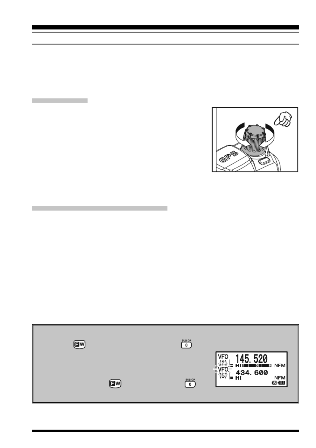
Sub Band Operation
When the key is pressed, followed by the key, the controls (except the TX
function) will act on the “Sub” band. When “Sub” Band
operation is activated, the “Sub” band “Frequency Con-
trol” icon will blink. After completing control of the
“Sub” band, press the key followed by the key
to return control to the “Main” band.
VX-8GR/GE OPERATING MANUAL18
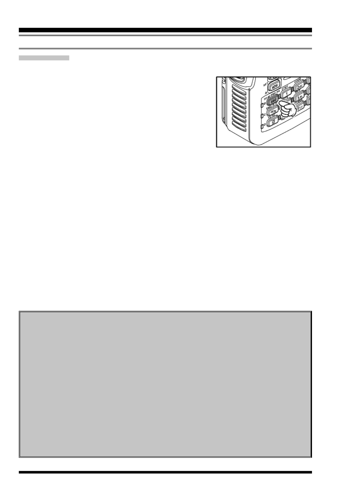
3) SCANNING
From the VFO mode, press and hold in the B key for one second, and while still
holding in the B key, rotate the DIAL knob to select
the bandwidth for the VFO scanner. Release the B key
to begin scanning toward a higher frequency. The scanner
will stop when it receives a signal strong enough to break
through the Squelch threshold. The VX-8GR/GE will then
hold on that frequency according to the setting of the “RE-
SUME” mode (Menu Item 77: SCAN RESUME).
If you wish to reverse the direction of the scan (i.e. toward a lower frequency, instead of a
higher frequency), just rotate the DIAL knob one click in the counter-clockwise direction
while the VX-8GR/GE is scanning. The scanning direction will be reversed. To revert to
scanning toward a higher frequency once more, rotate the DIAL knob one click clock-
wise.
Press the PTT switch briefly to cancel the scanning. See page 54 for more details regard-
ing Scan Operation.
OPERATION
FREQUENCY NAVIGATION
Dual Receive Notice
The VX-8GR/GE may receive very strong signals on the Image frequency, and/or
the receiver sensitivity may be somewhat reduced by the combination of the “A-
Band” and “B-Band” frequencies while Dual Receive operation is engaged.
If you experience interference that you suspect may be coming in via an “Image”
path, you may calculate the possible frequencies using the formulas below. This
information may be used in the design of effective countermeasures such as traps,
etc.
16.369 MHz x n11.7 MHz x n 9.8304 MHz x n
6.144 MHz x n4.9152 MHz x n(n is an integer: 1, 2, 3, …)
“A-Band” Freq. = (“B-Band” Freq. ± 46.35 MHz) x n
“B-Band” Freq. = (“A-Band” Freq. ± 47.25 MHz) x n (@ “A-Band” = NFM)

VX-8GR/GE OPERATING MANUAL 19
TRANSMISSION
Once you have set up an appropriate frequency inside one of the dual amateur bands on
which the VX-8GR/GE can transmit (144 MHz or 430 MHz), you’re ready to transmit.
These are the most basic steps; more advanced aspects of transmitter operation will be
discussed later.
1. To transmit, press the PTT switch, and speak into the
front panel microphone (located in the upper right-hand
corner of the speaker grille) in a normal voice level.
The LED of the “A” or “B” which is designated the
“Main” band will glow red during transmission.
2. To return to the receive mode, release the PTT switch.
3. During transmission, the relative power level will be
indicated on the LCD. Additionally, the “L1”, “ ”, “L2 L3”,
or “HI” icon will appear at the left side of the PO meter,
corresponding with the “Power” Level setting.
1) If you’re just talking to friends in the immediate
area, you’ll get much longer battery life by switching to Low Power opera-
tion. To do this, press the f key, then press the d key so that the “Low
Power” icon appears at the bottom of the display. And don’t forget: always have an
antenna connected when you transmit.
2) Transmission is not possible on the “Sub” band, nor on any frequencies other than
the 144 MHz and 430 MHz bands on the “Main” band.
3) Never transmit without having an antenna connected.
C HANGING THE TRANSMITTER POWER LEVEL
You can select between a total of four transmitter power levels on your VX-8GR/GE. The
exact power output will vary somewhat, depending on the voltage supplied to the trans-
ceiver. With the standard FNB-101LI Battery Pack and external DC source, the power
output levels available are: “L1”, “ ”, “L2 L3”, or “HI”
To change the power level:
1. The default setting for the power output is “High;” in
this configuration, the display shows the “HI” icon.
Pressing the f key, followed by the d key, causes
the power level “L1”, “L2”, or “L3” to appear.
2. Press the f key, followed by the d key (repeat-
edly, if necessary) to make the “HI” icon appear and
restore “High Power” operation.
OPERATION

VX-8GR/GE OPERATING MANUAL20
OPERATION
1) The VX-8GR/GE is smart! You can set up Low power on one band (like
UHF), while leaving VHF on High power, and the radio will remember the
different settings on each band.
And when you store memories, you can store
High and Low power settings separately in
each memory, so you don’t waste battery
power when using very close-in repeaters!
2) When you are operating on one of the Low
power settings, you can press the key, then press the PTT switch, to cause the VX-
8GR/GE to transmit (temporarily) on High power. After one transmission, the power
level will revert to the previously-selected Low power setting.
TRANSMISSION
FNB-101LI/-102LI
or EXT DC (7.4 V )
HI: 5.0 W,
L3: 2.5 W,
L2: 1.0 W,
L1: 0.05 W
TRANSMIT POWER
FBA-39
(w/Fresh Batteries )
L2: 1.0 W,
L1: 0.05 W
VX-8GR/GE OPERATING MANUAL 21
ADVANCED OPERATION
Now that you mastered the basics of VX-8GR/GE operation, let’s learn more about some
of the really neat features.
KEYBOARD LOCKING
In order to prevent accidental frequency change or inadvertent transmission, various keys
and switches may be locked out. The possible lockout combinations are:
KEY: Just the front panel keys are locked out
DIAL: Just the top panel DIAL knob is locked out
KEY&DIAL: Both the DIAL knob and Keys are locked out
PTT: The PTT switch is locked (TX not possible)
KEY&PTT: Both the keys and PTT switch are locked out
DIAL&PTT: Both the DIAL knob and PTT switch are locked out
ALL: All of the above are locked out
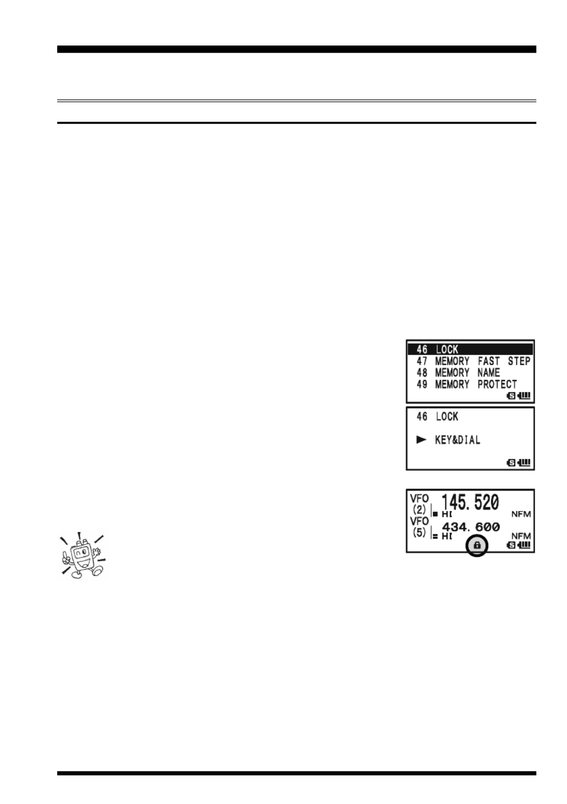
To lock out some or all of the keys:
1. Press and hold the m key for one second to enter the Set Mode.
2. Rotate the DIAL knob to select Set Mode Item 46: LOCK.
3. Press the m key briefly to enable selection of this Menu
Item.
4. Rotate the DIAL knob to choose between one of the lock-
ing schemes as outlined above.
5. When you have made your selection, press the PTT switch
to save the new setting and resume normal operation.
To activate the locking feature:
Press the p(PWR ) switch briefly. The “k” icon will appear
on the LCD. To cancel locking, press the p(PWR ) switch again.
Even when “ALL” keys have been locked out, one
key actually is not locked out: the p(PWR ) switch
remains available so you can unlock your keypad when you want to!

VX-8GR/GE OPERATING MANUAL22
A DJUSTING THE KEYPAD BEEPER VOLUME LEVEL
A keypad beeper provides useful audible feed back whenever a key button is pressed. The
keypad beeper level changes according to the receiver audio volume level setting. How-
ever, you may adjust the volume balance between the receiving audio and keypad beeper
using Set Mode Item 9: BEEP LEVEL.
1. Press and hold the m key for one second to enter the Set Mode.
2. Rotate the DIAL knob to select Set Mode Item 9: BEEP
LEVEL.
3. Press the m key briefly to enable selection of this Set
Mode Item.
4. Rotate the DIAL knob to select the desired level.
5. When you have made your choice, press the PTT switch to
save the new setting and return to normal operation.
Additionally, if you want to turn the beep off:
1. Press and hold the m key for one second to enter the Set Mode.
2. Rotate the DIAL knob to select Set Mode Item 11: BEEP
SELECT.
3. Press the m key briefly to enable selection of this Set
Mode Item.
4. Rotate the DIAL knob to change the setting to “OFF”.
5. When you have made your choice, press the PTT switch to
save the new setting and return to normal operation.
6. If you wish to re-enable the Beeper, just repeat the above
procedure, rotating the DIAL knob to select “KEY” or “KEY & SCAN” in step “4”
above.
KEY: The beeper sounds when you press any key.
KEY & SCAN: The beeper sounds when you press a key or when the scanner stops.
S ETTING THE FREQUENCY DISPLAY IMAGE IZE S
When operating in “Mono” band, pressing the a or b key, causes the LCD to “toggle”
between display of double-size characters and large characters. However, this feature
does not work during Dual Receive operation, as both the “Main” band and “Sub” band
frequencies are shown on the display.
ADVANCED OPERATION
LARGE CHARACTERS
D -OUBLE SIZE CHARACTERS

VX-8GR/GE OPERATING MANUAL 23
ADVANCED OPERATION
AUDIO MUTING
The Audio Mute feature is useful in situations where it would be helpful to reduce the
audio level of the “Receive Only” band (Small character display) whenever you receive a
signal on the “Main” band (Large character display) during Dual Receive operation.
To activate the Audio Mute feature:
1. Press the f key, then press the 7 key. This provides a “Short-
cut” to Set Mode Item 57: MUTE.
2. Rotate the DIAL knob to select the desired muting level
(MUTE 30%, MUTE 50%, MUTE 100%, or OFF).
3. When you have made your choice, press the PTT switch to save the new setting and
return to normal operation.
When the Audio Mute feature is activated, the “ ” icon will
appear on the display, and the “ ” icon blinks while muting the
“Receive Only” band audio.
To cancel the Audio Mute feature, just repeat the above proce-
dures, selecting “OFF” in step 2 above.
KEYPAD/LCD ILLUMINATION
Your VX-8GR/GE includes a reddish illumination lamp which aids in nighttime opera-
tion. The red illumination yields clear viewing of the display in a dark environment, with
minimal degradation of your night vision. Three options for activating the lamp are pro-
vided:
KEY 2sec - KEY 10sec: Illuminates the Keypad/LCD for the selected illumination
time when any key is pressed.
CONTINUOUS: Illuminates the Keypad/LCD continuously.
OFF: Disables the Keypad/LCD lamp.
Here is the procedure for setting up the Lamp mode:
1. Press and hold the m key for one second to enter the Set Mode.
2. Rotate the DIAL knob to select Set Mode Item 41: LAMP.
3. Press the m key briefly to enable selection of this Set Mode
Item.
4. Rotate the DIAL knob to select one of the three modes de-
scribed above.
5. When you have made your choice, press the PTT switch to
save the new setting and return to normal operation.

VX-8GR/GE OPERATING MANUAL24
C SHANGING THE CHANNEL TEPS
The VX-8GR/GE’s frequency synthesizer provides the option of utilizing tuning steps of
5, 6.25, 8.33, 10, 12.5, 15, 20, 25, 50 and 100 kHz per step. The VX-8GR/GE is set up at the
factory with different default steps for each operating band which are probably satisfactory
for most operation. However, if you need to change the channel step increments, the proce-
dure to do so is very easy.
1. Press the f key, then press the 1 key on the left side of the radio. This provides a
“Short-cut” to Set Mode Item 89: STEP FREQUENCY.
2. Rotate the DIAL knob to select the desired step size.
3. Press the PTT switch to save the new setting and return to
normal operation.
1) 8.33 kHz steps are available only when receiving on the Air band.
2) 5 kHz steps are not available for use on 250 - 300 MHz, nor above 580
MHz.
C HANGING THE RECEIVING MODE
The VX-8GR/GE provides for automatic mode changing when the radio is tuned to dif-
ferent operating frequencies. However, should an unusual
receiving situation arise in which you need to change to a
different receiving mode, just press the key. The re-
ceiving modes available are:
AUTO: The receive mode is automatically set accord-
ing to the default values for the selected fre-
quency range
NFM: Frequency Modulation
AM: Amplitude Modulation
Unless you have a compelling reason to do so, leave the Automatic Mode
Selection feature on in order to save time and trouble when changing bands.
If you make a mode change for a particular frequency or station, you can
always store that one channel into memory, as the mode setting will be memorized along
with the frequency information.
ADVANCED OPERATION

VX-8GR/GE OPERATING MANUAL 25
ADVANCED OPERATION
SQL S-METER
A special SQL (Squelch) S-meter feature is provided on this radio. This feature allows
you to set the squelch so only signals exceeding a certain S-meter level will open the
squelch.
To set up the S-meter squelch feature for operation, use the following procedure:
1. Press and hold the m key for one second to enter the Set Mode.
2. Rotate the DIAL knob to select Set Mode Item 86: SQL S-
METER.
3. Press the m key briefly to enable selection of this Set
Mode Item.
4. Rotate the DIAL knob to select the desired signal strength
level for the squelch threshold (LEVEL1 - LEVEL9 or OFF).
5. When you have made your choice, press the PTT switch to
save the new setting and return to normal operation.
1) When the SQL S-meter is activated, the S-meter segment corresponding to
the squelch threshold which was set by step 4 above will blink.
2) The receiver’s squelch will open based on the higher of the levels set by the
Noise Squelch or the S-meter Squelch system.
For example:
a) If the Noise Squelch (SQL control) is set so that signals at a level of “S-3” will open
the squelch, but the SQL S-meter (Set Mode Item 93) is set to “LEVEL 5,” the squelch
will only open on signals which are “S5” or stronger on the S-meter.
b) If the SQL S-meter is set to “S3,” but the Noise Squelch is set to a high level which
will only pass signals which are Full Scale on the S-meter, the squelch will only open on
signals which are Full Scale on the S-meter. In this case, the Noise Squelch overrides
the action of the S-meter Squelch.

VX-8GR/GE OPERATING MANUAL26
REPEATER OPERATION
GENERAL
Repeater stations, usually located on mountaintops or other high locations, provide a dra-
matic extension of the communication range for low-powered hand-held or mobile trans-
ceivers. The VX-8GR/GE includes a number of features, which make repeater operation
simple and enjoyable.
REPEATER SHIFTS
Your VX-8GR/GE has been configured, at the factory, for the repeater shifts customary in
your country. For the 144 MHz band, this usually will be 600 kHz, while the 430 MHz
shift will be 1.6 MHz, 7.6 MHz, or 5 MHz (USA version).
Depending on the part of the band in which you are operating, the repeater shift may be
either downward ( ) or upward ( ),
and one of these icons will appear to
the right of the display frequency on
the LCD when repeater shifts have
been enabled.
AUTOMATIC REPEATER SHIFT (ARS)
The VX-8GR/GE provides a convenient Automatic Repeater Shift feature, which causes
the appropriate repeater shift to be automatically applied whenever you tune into the des-
ignated repeater sub-bands in your country. These sub-bands are shown below.
If the ARS feature does not appear to be working, you may have accidentally disabled it.
To re-enable ARS:
1. Press and hold the m key for one second to enter the Set Mode.
2. Rotate the DIAL knob to select Set Mode Item 69: RPT ARS.
3. Press the m key briefly to enable selection of this Set
Mode Item.
4. Rotate the DIAL knob to select “ON”(to enable Automatic
Repeater Shift).
5. When you have made your choice, press the PTT switch to
save the new setting and return to normal operation.
ARS-Repeater Subbands
European Version
Version A
2-m
145.1 145.5
145.6 145.8
146.0 146.4 147.0 147.6 148.0
146.6 147.4
Version A
70-cm
440.0 445.0 450.0
Euro Version 1
Euro Version 2
439.45438.20
433.00 434.60433.40 435.00

VX-8GR/GE OPERATING MANUAL 27
MANUAL REPEATER SHIFT ACTIVATION
If the ARS feature has been disabled, or if you need to set a repeater shift direction other
than that established by the ARS, you may set the direction of the repeater shift manually.
To do this:
1. Press the f key, then press the 6 key. This provides a “Short-cut” to Set Mode
Item 70: RPT SHIFT.
2. Rotate the DIAL knob to select the desired shift among
“–RPT,” “+RPT SIMPLEX,” and “ .”
3. Press the PTT switch to save the new setting and exit to
normal operation.
C HANGING THE DEFAULT REPEATER SHIFTS
If you travel to a different region, you may need to change the default repeater shift, to
ensure compatibility with local operating requirements.
To do this, follow the procedure below:
1. Press and hold the m key for one second to enter the Set Mode.
2. Rotate the DIAL knob to select Set Mode Item 71: RPT
SHIFT FREQ.
3. Press the m key briefly to enable selection of this Set
Mode Item.
4. Rotate the DIAL knob to select the new repeater shift mag-
nitude.
5. Press the PTT switch to save the new setting and return to
normal operation.
If you just have one “odd” split that you need to program, don’t change the
default repeater shift! Enter the transmit and receive frequencies separately,
as shown on page 44.
REPEATER OPERATION

VX-8GR/GE OPERATING MANUAL28
REPEATER OPERATION
T ONE CALLING (1750 HZ)
If your transceiver is VX-8GE (European version), press and hold in the e switch (just
below the PTT switch) to generates a 1750-Hz burst tone to access the European repeater.
The transmitter will automatically be activated, and a 1750-Hz audio tone will be super-
imposed on the carrier. Once access to the repeater has been gained, you may release the
e switch, and use the PTT switch for activating the transmitter thereafter.
If you need to access the repeaters which requires a 1750-Hz burst tone for access by the
VX-8GR (USA/EXP versions), you can set the e switch to serve as a “Tone Call”
switch instead. To change the configuration of this switch, we again use the Set Mode to
help us.
1. Press and hold the m key for one second to enter the Set Mode.
2. Rotate the DIAL knob to select Set Mode Item 56: MONI/T-
CALL.
3. Press the m key briefly to enable adjustment of this Set
Mode Item.
4. Rotate the DIAL knob to select “T-CALL” on the display.
5. Press the PTT switch briefly to save the new setting and
exit to normal operation.
To access a repeater, press and hold in the e key for the amount
of time specified by the repeater owner/operator. The transmitter will automatically be
activated, and a 1750-Hz audio tone will be superimposed on the carrier. Once access to
the repeater has been gained, you may release the e key, and use the PTT switch for
activating the transmitter.
C HECKING THE REPEATER UPLINK I( NPUT) FREQUENCY
It often is helpful to be able to check the uplink (input) frequency of a repeater, to see if the
calling station is within direct (“Simplex”) range.
To do this, just press the h key. You’ll notice that the display has shifted to the repeater
uplink frequency. Press the h key again to cause operation to
return to normal monitoring of the repeater downlink (output)
frequency. While you are listening on the input frequency of the
repeater using the h key, the repeater offset icon (“ ” or ”)
will blink.
The configuration of h key may be set either to “RV” (for checking the
input frequency of a repeater, or “HM” (for instant switching to the “Home”
channel for the band you are operating on). To change the configuration of
h key, use Set Mode Item 34: HOME/REVERSE. See page 135.
VX-8GR/GE OPERATING MANUAL 29
CTCSS OPERATION
Many repeater systems require that a very-low-frequency audio tone be superimposed on
your FM carrier in order to activate the repeater. This helps prevent false activation of the
repeater by radar or spurious signals from other transmitters. This tone system, called
“CTCSS” (Continuous Tone Coded Squelch System), is included in your VX-8GR/GE,
and is very easy to activate.
CTCSS setup involves two actions: setting the Tone Frequency and then set-
ting the Tone Mode. These functions are set up using Set Mode Items 88:
SQL TYP and 91: TONE FREQUENCY.
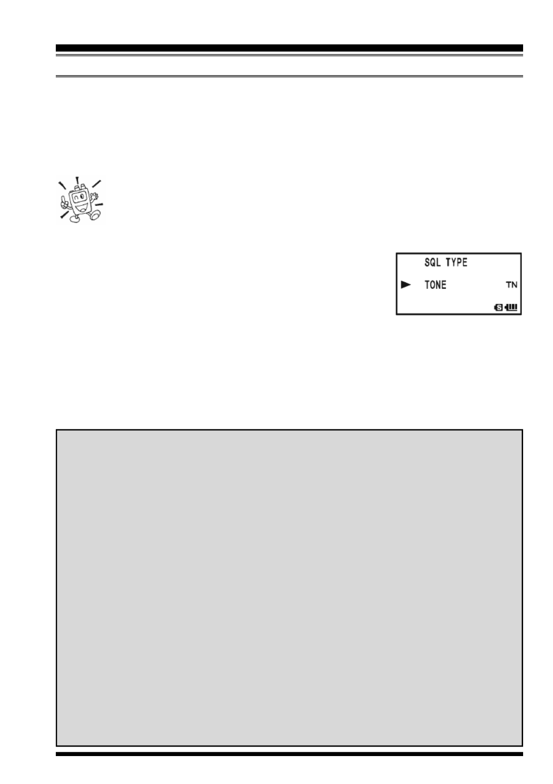
1. Press the f key, then press the M key. This provides a “Short-cut” to Set Mode
Item 88: SQL TYPE.
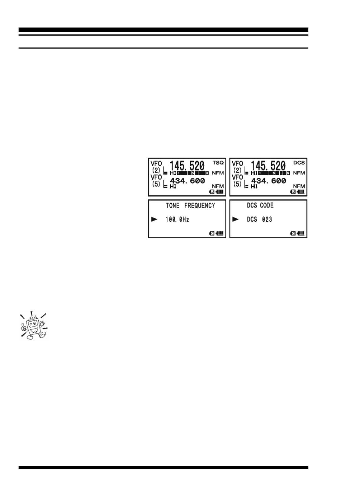
2. Rotate the DIAL knob so that “TONE” appears on the dis-
play. This activates the CTCSS Encoder.
3. Rotation of the DIAL knob one more “click” in step “2”
above will also activate the “TSQ” decode function. When “TSQ” is displayed, the
Tone Squelch system is active, which mutes your VX-8GR/GE’s receiver until it
receives a call from another radio sending out a matching CTCSS tone. This can
helpful in a high RF congested location by keeping your radio quiet until a call is
received from a specific station with a matching CTCSS tone.
CTCSS/DCS/EPCS OPERATION
You may notice an additional “DCS” indication appearing while you rotate
the DIAL knob in step 3 above. We’ll discuss the Digital Code Squelch sys-
tem shortly.
You may notice “REV TONE” indicated on the display while you rotate the
DIAL knob in step 3 above. When the Reverse Tone Squelch system is ac-
tive, the VX-8GR/GE’s receiver is muted when it receives a call from a radio
sending a matching CTCSS tone. The “RTN” icon will appear on the display
when the Reverse Tone Squelch system is activated.
You may notice “PR FREQ” indicated on the display while you rotate the
DIAL knob in step 3 above. This means the user programmed Reverse CTCSS
Decoder will mute your VX-8GR/GE’s receiver when it receives a call from
a radio sending a CTCSS tone matching your programmed tone (determine
by Set Mode Item 65: PR FREQUENCY). The “PR” icon will appear on the
display when the Reverse CTCSS Decoder is activated.
You may notice “PAGER” and “MESSAGE” indication on the display while
you rotate the DIAL knob in step 3 above. These appear when the “Enhanced
Paging & Code Squelch” and the “Message Feature” are activated. We’ll
discuss these functions later.

VX-8GR/GE OPERATING MANUAL30
4. When you have made your selection of the CTCSS tone mode, press the M key to
save the new setting and exit to normal operation.
5. Press the f key, then press the 2 key. This provides a “Short-cut” to Set Mode
Item 91: TONE FREQUENCY.
6. Rotate the DIAL knob until the display indicates the fre-
quency of the CTCSS tone that you need to send on your
transmission (ask the repeater owner/operator if you don’t
know the tone frequency).
7. When you have made your selection, press the 2 key briefly to save the new setting
and exit to normal operation. This is different from the usual method of restoring
normal operation, and it applies only to the configuration of the CTCSS/DCS fre-
quencies.
1) The repeater may or may not
re-transmit a CTCSS tone - some
systems just use CTCSS to control
access to the repeater, but do not pass it along
when transmitting. If the S-Meter deflects,
but you cannot hear the audio, repeat steps
“1” through “4” above, but rotate the DIAL
so that “TSQ” disappears - this will allow
you to hear all traffic on the channel being
received.
2) During CTCSS operation, you may set up the VX-8GR/GE so a ringing “bell” sound
alerts you to an incoming call. See page 37 for details.
3) You may set up the VX-8GR/GE so a vibration alerts you to an incoming call, during
CTCSS operation. See page 40 for details.
CTCSS/DCS/EPCS OPERATION
CTCSS TONE FREQUENCY (Hz)
67.0 69.3 71.9 74.4 77.0 79.7
82.5 85.4 88.5 91.5 94.8 97.4
100.0 103.5 107.2 110.9 114.8 118.8
123.0 127.3 131.8 136.5 141.3 146.2
151.4 156.7 159.8 162.2 165.5 167.9
171.3 173.8 177.3 179.9 183.5 186.2
189.9 192.8 196.6 199.5 203.5 206.5
210.7 218.1 225.7 229.1 233.6 241.8
250.3 254.1 – – – –
CTCSS OPERATION

VX-8GR/GE OPERATING MANUAL 31
DCS OPERATION
Another form of tone access control is Digital Code Squelch, or DCS. It is a newer, more
advanced tone system which generally provides more immunity from false paging than
does CTCSS. The DCS Encoder/Decoder is built into your VX-8GR/GE, and operation is
very similar to that just described for CTCSS. Your repeater system may be configured for
DCS. The DCS Squelch may be quite useful in Simplex operation if your friends use
transceivers equipped with this advanced feature.
Note: Just as in CTCSS operation, DCS requires that you set the Tone Mode to DCS
and that you select a DCS code.
1. Press the f key, then press the M key. This provides a
“Short-cut” to Set Mode Item 88: SQL TYPE.
2. Rotate the DIAL knob until “DCS” appears on the display;
this activates the DCS Encoder/Decoder.
3. Press the M key to save the new setting and exit to nor-
mal operation.
4. Press the f key, then press the 2 key. This provides a
“Short-cut” to Set Mode Item 21: DCS CODE.
5. Rotate the DIAL knob to select the desired DCS Code (a three-digit number). Ask the
repeater owner/operator if you don’t know DCS Code; if you are working simplex,
just set up the DCS Code to be the same as that used by your friends.
6. When you have made your selection, press the 2 key to save the new settings and
exit to normal operation.
1) Remember that the DCS is an
Encode/Decode system, so your
receiver will remain muted until
a matching DCS code is received on an in-
coming transmission. Switch the DCS off
when you’re just tuning around the band!
2) During DCS operation, you may set up
the VX-8GR/GE so a ringing “bell” sound
alerts you to an incoming call. See page 37
for details.
3) You may set up the VX-8GR/GE so a vi-
bration alerts you to an incoming call, during DCS operation. See page 40 for details.
CTCSS/DCS/EPCS OPERATION
DCS CODE
023 025 026 031 032 036 043 047 051 053
054 065 071 072 073 074 114 115 116 122
125 131 132 134 143 145 152 155 156 162
165 172 174 205 212 223 225 226 243 244
245 246 251 252 255 261 263 265 266 271
274 306 311 315 325 331 332 343 346 351
356 364 365 371 411 412 413 423 431 432
445 446 452 454 455 462 464 465 466 503
506 516 523 526 532 546 565 606 612 624
627 631 632 654 662 664 703 712 723 731
732 734 743 754 – – – – – –
VX-8GR/GE OPERATING MANUAL32
DCS CODE INVERSION
The DCS system was first introduced in the commercial LMR (Land Mobile Radio) ser-
vice, where it is now in widespread use. DCS is sometime referred to by its different
proprietary names, such as DPL® (Digital Private Line®, a registered trademark of Motorola,
Inc.).
DCS uses a codeword consisting of a 23-bit frame, transmitted (sub audible) at a data rate
of 134.4 bps (bit/sec). Occasionally, signal inversion can result in the complement of a
code being sent or received. This prevents the receiver’s squelch from opening with DCS
enabled, as the decoded bit sequence would not match that selected for operation.
Typical situations that might cause inversion to occur are:
Connection of an external receiver preamplifier.
Operating through a repeater.
Connection of an external linear amplifier.
Note that code inversion does not mean that any of the above listed equipment is defective!
In certain amplifier configurations, the output signal (phase) is inverted from the input. Small
signal or power amplifiers having an odd number (1, 3, 5, etc.) of amplification stages may
result in inversion of a transmitted or received DCS code. While under most circumstances
this should not occur (amplifier designs and industry standards take this into account), if you
find that your receiver squelch does not open when both you and the other station are using a
common DCS code, you or the other station (but not both) can try the following:
1. Press and hold the m key for one second to enter the Set Mode.
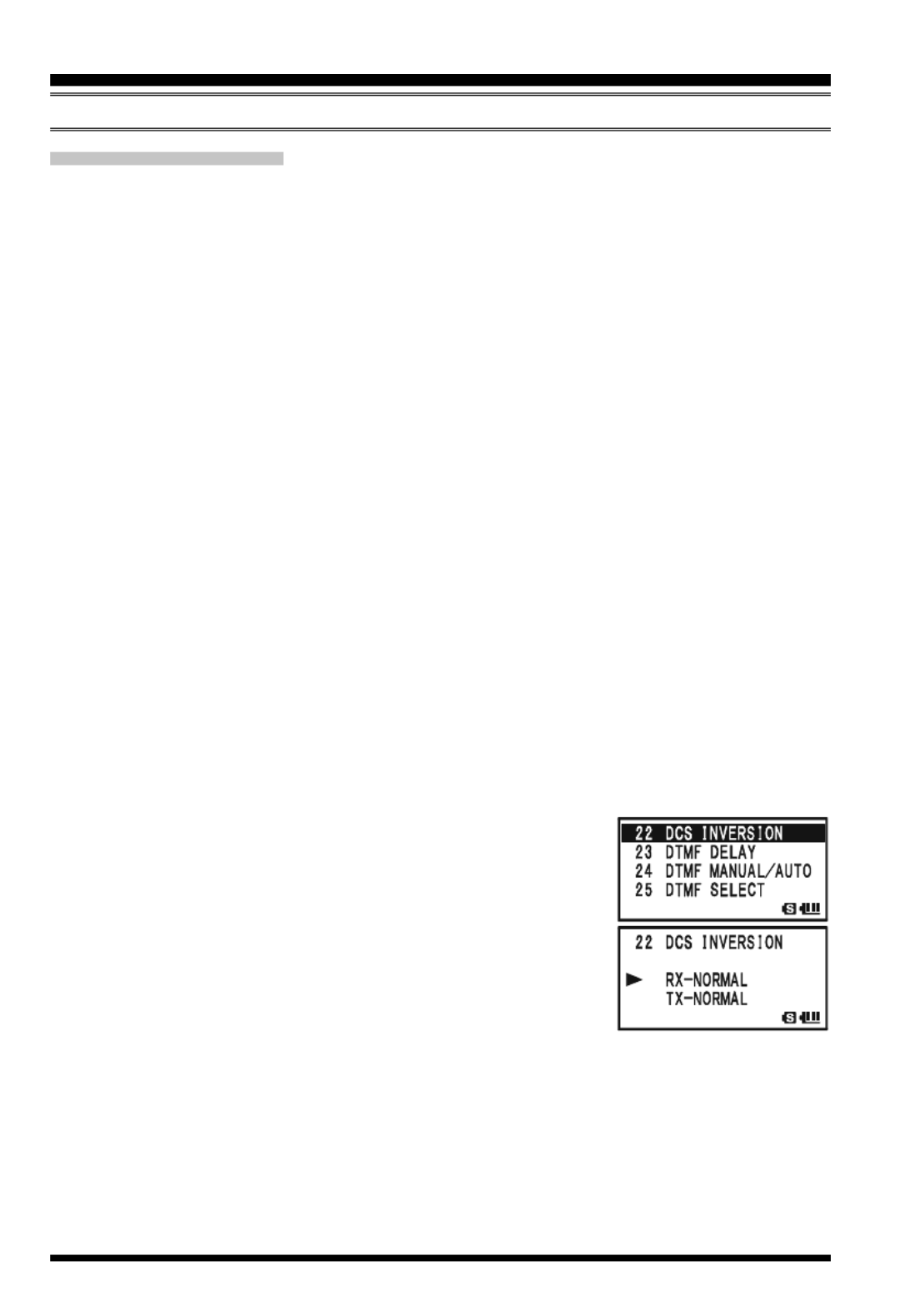
2. Rotate the DIAL knob to select Set Mode Item 22: DCS
INVERSION.
3. Press the m key briefly to enable adjustment of this Set
Mode Item.
4. Rotate the DIAL knob to select one of the following modes:
RX-NORMAL, TX-NORMAL:
Receive and transmit the Normal DCS Tone.
RX-INVERT, TX-NORMAL:
Receive the Inverted DCS Tone and transmit the Normal DCS Tone.
RX-BOTH, TX-NORMAL:
Receive both Normal and Inverted DCS Tones and transmit the Normal DCS
Tone.
RX-NORMAL, TX-INVERT:
Receive the Normal DCS Tone and transmit the Inverted DCS Tone.
CTCSS/DCS/EPCS OPERATION
DCS OPERATION

VX-8GR/GE OPERATING MANUAL 33
RX-INVERT, TX-INVERT:
Receive and transmit the Inverted DCS Tone.
RX-BOTH, TX-INVERT:
Receive both Normal and Inverted DCS Tones and transmit the Inverted DCS
Tone.
5. When you have made your selection, press the PTT switch, to save the new settings
and exit to normal operation.
This is different from the usual method of restoring normal operation, and it applies only
to the configuration of the CTCSS/DCS frequencies. Remember to restore the default
setting “RX-NORMAL, TX-NORMAL” (Receive and transmit the Normal DCS Tone) when
done.
CTCSS/DCS/EPCS OPERATION
DCS OPERATION
VX-8GR/GE OPERATING MANUAL34
T S SONE EARCH CANNING
In operating situations where you don’t know the CTCSS or DCS tone being used by
another station, you can command the radio to listen to the incoming signal and scan in
search of the tone being used. Two things must be remembered in this regard:
You must be sure that your repeater uses the same tone type (CTCSS vs. DCS).
Some repeaters do not pass the CTCSS tone; you may have to listen to the station
transmitting on the repeater uplink (input) frequency in order to allow Tone Search
Scanning to work.
To scan for the tone in use:
1. Set the radio up for either CTCSS or DCS Decoder operation (see the previous dis-
cussion). In the case of CTCSS,
“TSQ” will appear on the display;
in the case of DCS, “DCS” will
appear on the display.
2. Press the f key, then press the
2 key to recall the Set Mode
Item 91: TONE FREQUENCY
when CTCSS is selected, or Menu
Item 21: DCS CODE during DCS operation.
3. Press and hold in the key, the “BTONE SEARCH” notation will appear, release
the B key to start scanning for the incoming CTCSS or DCS tone/code.
4. When the radio detects the correct tone or code, it will halt on that tone/code, and
audio will be allowed to pass. Press the B key to lock in that tone/code, then press
the 2 key to exit to normal operation.
If the Tone Scan feature does not detect a tone or code, it will continue to
scan indefinitely. When this happens, it may be that the other station is not
sending any tone. You can press the PTT switch to halt the scan at any time.
You can also press the e key during Tone Scanning to listen to the (muted) signal from
the other station. When you release the e key, Tone Scanning will resume after about a
second.
Tone Scanning works either in the VFO or Memory modes.
CTCSS/DCS/EPCS OPERATION
VX-8GR/GE OPERATING MANUAL 35
CTCSS/DCS/EPCS OPERATION
EPCS (E P SNHANCED AGING & CODE QUELCH )
The VX-8GR/GE includes an Enhanced CTCSS tone encoder/decoder and a dedicated
microprocessor providing paging and selective calling features. This allows you to place
a call to a specific station (Paging), and to receive calls of your choice directed only to you
(Code Squelch).
The paging and code squelch systems use two pairs of (alternately switched) CTCSS
tones which are stored in the pager memories. Basically, your receiver remains silent until
it receives the CTCSS tone pair that matches those stored in the Receiving Pager Memory.
The squelch then opens so the caller is heard, and the paging ringer immediately sounds,
if activated. When you close the PTT switch to transmit, the CTCSS tone pair that is
stored in the Transmitting Pager Memory will be transmitted automatically.
On the paged radio, the Code Squelch will close automatically after the incoming page
ends. Meanwhile, on the paging radio, the Enhanced Paging and Code Squelch system
will be disabled after the PTT switch is released after the paging transmission. You may
re-activate the Enhanced Paging and Code Squelch system again.
S TORING THE CTCSS TONE PAIRS FOR EPCS OPERATION
1. Press and hold the m key for one second to enter the Set Mode.
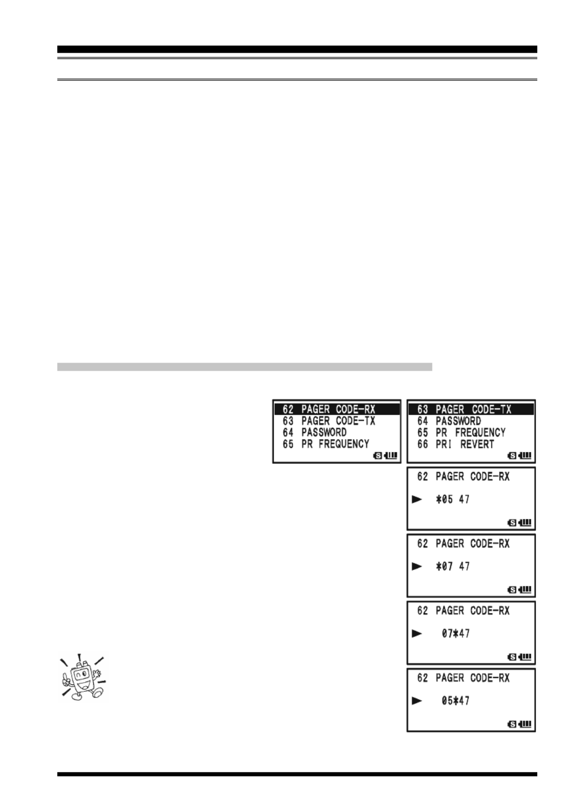
2. Rotate the DIAL knob to select Set
Mode Item 62: PAGER CODE-RX
for the Receiving CTCSS Tone
Pair or Set Mode Item 63: PAGER
CODE-TX for the Transmitting CTCSS Tone Pair.
3. Press the m key briefly to enable adjustment of this Set
Mode Item.
4. Rotate the DIAL knob to set the CTCSS Tone number which
corresponds to the first tone of the CTCSS Tone Pair.
5. Press the M key (“” icon moves to the right), then
rotate the DIAL knob to set the CTCSS Tone number, which
corresponds to the second tone of the CTCSS Tone Pair.
6. Press the PTT switch to save the new setting and exit to
normal operation.
The VX-8GR/GE does not recognize the order of
the 1st tone and the 2nd tone. In other words, for
example, the VX-8GR/GE considers both CTCSS
pairs “10, 35” and “35, 10” to be identical.
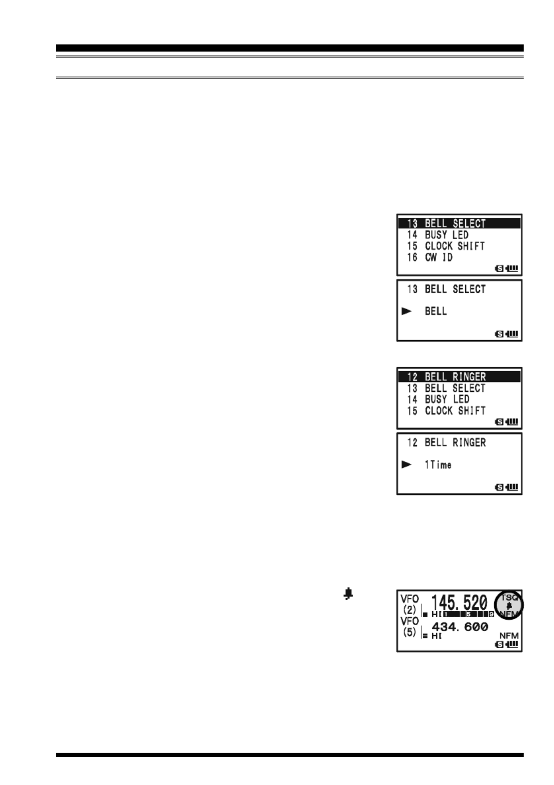
VX-8GR/GE OPERATING MANUAL 37
CTCSS/DCS/EPCS BELL OPERATION
During CTCSS Decode, DCS, or EPCS operation, you may set up the VX-8GR/GE so
that a ringing “bell” sound alerts you that a call is coming in. Here is the procedure for
activating the CTCSS/DCS/EPCS Bell:
1. Set the operating frequency to the desired channel.
2. Set the transceiver up for CTCSS Decode (“Tone Squelch”), DCS, or EPCS opera-
tion, as described previously.
3. Press and hold the m key for one second to enter the Set Mode.
4. Rotate the DIAL knob to select Set Mode Item 13: BELL
SELECT.
5. Press the m key briefly to enable adjustment of this Set
Mode Item.
6. Rotate the DIAL knob to set the desired “bell” sound. The
available choices are BELL, USER BP1, USER BP2, USER
BP3, or OFF (disable the Bell function).
Note: When User Beep (described later) does not register,
USER BP1, USER BP2 USER BP3, or does not appear.
7. Press the m key briefly, then rotate the DIAL knob one
click counter-clockwise to select Set Mode Item 12: BELL
RINGER.
8. Press the m key briefly to enable adjustment of this Menu
Item.
9. Rotate the DIAL knob to set the desired number of rings of
the Bell. The available choices are 1Time through 20Times
or CONTINUOUS.
10. Press the PTT switch briefly to save the new setting and exit to normal operation.
When you are called by a station whose transceiver is sending a CTCSS tone, DCS code,
or CTCSS tone pair which matches that set into your Decoder, the Bell will ring in accor-
dance with this programming.
When the CTCSS/DCS/EPCS Bell is activated, the “ ” icon
will appear in the display.
To disable the CTCSS/DCS/EPCS Bell function, select the set-
ting of Set Mode Item 11: BELL SELECT to “OFF”.
CTCSS/DCS/EPCS OPERATION

VX-8GR/GE OPERATING MANUAL38
CTCSS/DCS/EPCS OPERATION
P UROGRAMMING THE SER MELODY
Three User Beep Memories are provided, allowing you to create unique original beep
tone melodies.
Each User Beep Memory can store up to 64 steps with three octaves (“C1” through “B3”).
1. Press and hold the m key for one second to enter the Set Mode.
2. Rotate the DIAL knob to select Set Mode Item 10: BEEP
MELODY.
3. Press the m key briefly to enable adjustment of this Set
Mode Item.
4. Rotate the DIAL knob to select the memory slot into which
you wish to store your programmed beep melody. Avail-
able selections are 1 2, , and 3. The previously stored beep
melody will be displayed.
5. Press the M key to enable programming the beep melody.
Press and hold the h key for one second to clear any
previous beep melody, if desired.
6. Rotate the DIAL knob to select the first beep tone of the
User Beep Melody. Available selections are C1 - B3, and
POS (rest).
7. Press the M key, then rotate the DIAL knob to set the
length of the first beep tone. Available selections are 10ms
(10 msec) - 2500ms (2.5 sec).
8. Press the M key to accept the first beep tone of the User
Beep Melody.
9. If you make a mistake, press the B key to back-space
the cursor, then re-enter the correct beep tone or length.
10. Repeat steps 6 - 9 until you have completed the User Beep
Melody.
11. When there is a beep tone, which you wish to delete, bring
the cursor to that beep tone using the B M/ key, then
press the c key repeatedly until the “SELECT” notation
in the “Operation Mode” slot turns into “DELETE”. Now,
press and hold in the c key for one second to delete that beep tone.
CTCSS/DCS/EPCS BELL OPERATION
C2C1 C3D2D1 D3E2E1 E3F2F1 F3G2G1 G3A2A1 A3B2B1 B3
Step Operation Mode
Memory Slot Tone Length
Beep Tone
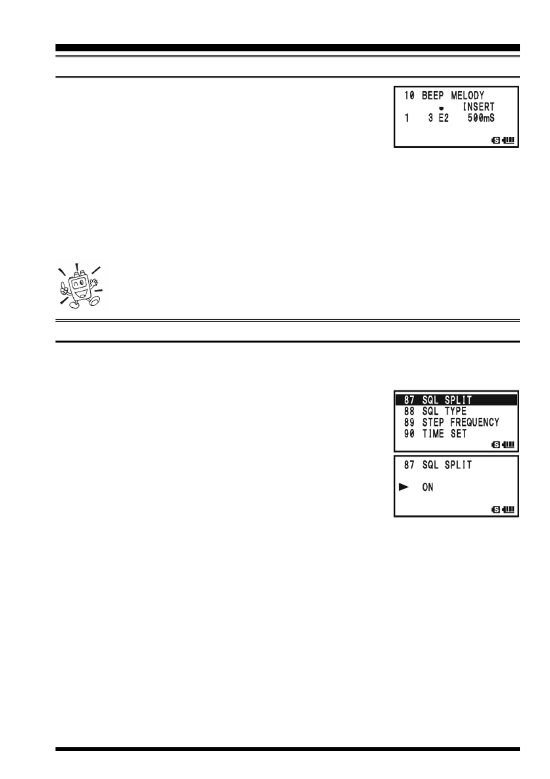
VX-8GR/GE OPERATING MANUAL 39
12. When you wish to add a beep tone into the beep melody
strings, move the cursor to the place where you wish to en-
ter the beep tone using the B M/ key, then press the
c key repeatedly until the “SELECT” notation in the “Op-
eration Mode” slot turns into “INSERT”. Now, press and hold in the c key for one
second to add the new beep tone (Tone: “C2”, Tone Length: “500mS”).
13. Press and hold the
h key for one second to delete all data after the current position
that may have previously been stored in the User Beep Melody.
14. When you have programmed User Beep Melody, press the PTT switch briefly to save
the new setting and exit to normal operation.
You may check your work by monitoring the programmed User Beep Melody.
To do this, repeat steps 1 - 4 above, then press the f key.
SPLIT TONE OPERATION
The VX-8GR/GE can be operated in a Split Tone configuration via the Set mode.
1. Press and hold the m key for one second to enter the Set Mode.
2. Rotate the DIAL knob to select Set Mode Item 87: SQL
SPLIT.
3. Press the m key briefly to enable adjustment of this Set
Mode Item.
4. Rotate the DIAL knob to select “ON” (to enable the Split
Tone feature).
5. Press the PTT switch briefly to save the new setting and
exit to normal operation.
When the Split Tone feature is activated, you can see the following additional parameters
after the “MESSAGE” parameter while selecting the Set Mode Item 88: SQL TYPE:
D CD: DCS Encode only (“DC” icon will appear while operating)
TONE-DCS: Encodes a CTCSS Tone and Decodes a DCS code
(the “T-D” icon will appear during operation)
D CD-TONE SQL: Encodes a DCS code and Decodes a CTCSS Tone
(the “D-T” icon will appear during operation)
Select the desired operating mode from the selections shown above.
CTCSS/DCS/EPCS OPERATION
CTCSS/DCS/EPCS BELL OPERATION

VX-8GR/GE OPERATING MANUAL40
CTCSS/DCS/EPCS VIBRATOR OPERATION
The CTCSS/DCS/EPCS Vibrator operation is similar to the CTCSS/DCS/EPCS BELL
operation. The CTCSS/DCS/EPCS Vibratory operation inform you that a call is coming
in by vibration, during CTCSS Decode, DCS, or EPCS operation. Here is the procedure
for activating the CTCSS/DCS/EPCS Vibrator:
1. Set the operating frequency to the desired channel.
2. Set the transceiver up for CTCSS Decode (“Tone Squelch”), DCS, or EPCS opera-
tion, as described previously.
3. Press and hold the m key for one second to enter the Set Mode.
4. Rotate the DIAL knob to select Set Mode Item 97: VIBRA-
TOR.
5. Press the m key briefly to enable adjustment of this Set
Mode Item.
6. Rotate the DIAL knob to select “SIGNALING”.
Note: When this item is set to “BUSY”, the VX-8GR/GE
vibrates when any signal is received without regard to the
CTCSS, DCS, or EPCS decoder.
7. Press the m key briefly, then rotate the DIAL knob one
click clockwise to select Set Mode Item 98: VIBRATOR
MODE.
8. Press the m key briefly to enable adjustment of this Menu
Item.
9. Rotate the DIAL knob to set the desired vibrating mode.
The available choices are:
MODE1: The VX-8GR/GE vibrates continuously.
MODE2: The VX-8GR/GE vibrates at a long interval.
MODE3: The VX-8GR/GE vibrates at a short interval.
10. Press the PTT switch briefly to save the new setting and exit to normal operation.
When you are called by a station whose transceiver is sending a CTCSS tone, DCS code,
or CTCSS tone pair which matches that set into your Decoder, the VX-8GR/GE will
vibrate in accordance with this programming.
When the CTCSS/DCS/EPCS Vibrator operation is activated,
the “dashed line” will appear under the mode icon.
To disable the CTCSS/DCS/EPCS Vibrator operation, select the
setting of Set Mode Item 97: VIBRATOR to “OFF”.
CTCSS/DCS/EPCS OPERATION

VX-8GR/GE OPERATING MANUAL 41
CTCSS/DCS/EPCS OPERATION
1) The vibrator operation can be set independently on each operating band
of both VFO A and VFO B.
2) When the vibrator is activated, press any key, rotate the DIAL knob, or
during a transmission, the vibrator will halt temporarily. The “under line” or “dashed
line” under the mode icon will blink during this pause. Five seconds after any of the
above operations, the vibrator will resume.
CTCSS/DCS/EPCS VIBRATOR OPERATION

VX-8GR/GE OPERATING MANUAL 43
MEMORY MODE (REGULAR MEMORY CHANNEL OPERATION )
MEMORY STORAGE
1. Select the desired frequency, while operating in the VFO mode. Be sure to set up any
desired CTCSS or DCS tones, as well as any desired repeater offset. The power level
may also be set at this time, if you wish to store it.
2. Press and hold in the f key for 1/2 second.
3. Within five seconds of releasing the f key, you need to make a decision regarding
channel storage. The microprocessor will automatically se-
lect the next-available “free” channel (a memory register
on which no data has been stored). If you do not wish to
make a change and accept the “free” channel, proceed to
step 4. If you wish to select a different channel number into which to store the data,
rotate the DIAL knob to select the desired memory channel.
Advice: You may jump 100 memory channels, if you’re in a hurry (101 201 301 …),
by pressing the m key (multiple times, if necessary). If you see the “ ” icon at the
upper left of the channel number, it means that the channel currently has no data
written on it (i.e. the channel is “free”: the occupied channel displays the “ ” icon).
4. Press the f key once more to store the frequency into memory.
5. You still will be operating in the “VFO” mode, so you may now enter other frequen-
cies, and store them into additional memory locations, by repeating the above pro-
cess.
1) You may change the automatic memory channel selection feature to select
the “next-highest memory channel above the last-stored memory channel”
instead of the “next-available ‘free’ channel” via the Set Mode Item 51:
MEMORY WRITE; see page 138.
2) You may disable the memory write function which prevents a memory write operation
if you should accidentally perform a wrong key sequence via the Set Mode Item 49:
MEMORY PROTECT. See page 138 for details. When the memory write protect is acti-
vated, the “PROTECT” notation appears on the display while a memory write opera-
tion is being performed.
3) You may change the duration time of the secondary function (press and holding the
key) of the f key via the Set Mode Item 31: FW KEY HOLD TIME; see page 135.
IMPORTANT NOTE
On rare occasions the memorized data may become corrupted by miss operation,
or static electricity. When repairs are made the memory data may be lost. Please
write down or record the memorized information so you will be able to restore it if
needed.

VX-8GR/GE OPERATING MANUAL44
MEMORY MODE (REGULAR MEMORY CHANNEL OPERATION )
MEMORY STORAGE
STORING INDEPENDENT T FRANSMIT REQUENCIES (“O ”DD SPLITS )
All memories can store an independent transmit frequency, for operation on repeaters
with non-standard shift. To do this:
1. Store the receive frequency using the method already described under M -EMORY STOR
AGE (it doesn’t matter if a repeater offset is active).
2. Tune to the desired transmit frequency, then press and hold in the f key for 1/2
second.
3. Within five seconds of releasing the f key, rotate the DIAL knob to select the same
memory channel number as used in step “1” above.
4. Press and hold in the PTT switch, then briefly press the f key once more while
holding the PTT switch in (this does not key the transmitter).
Whenever you recall a memory, which contains in-
dependently-stored transmit and receive frequen-
cies, the “ ” indication will appear in the display.
MEMORY RECALL
1. While operating in the VFO mode, press the c key to
enter the Memory mode.
2. Rotate the DIAL knob to select the desired channel.
3. If you press the f key briefly, then rotate the DIAL knob,
the memory channel will be selected in 10 channels per step.
4. To return to the VFO mode, press the c key.
1) When the radio is already set to the Memory mode, an easy way to recall
memories is to key in the memory channel number, then press the c key.
For example, to recall memory channel #14, press 1 4 c .
2) You may change the step of the fast channel selection mode (f key + DIAL knob )
via Set Mode Item 47: MEMORY FAST STEP. See page 137 for details.

VX-8GR/GE OPERATING MANUAL 45
A special one-touch “HOME” channel is available for each operating band, to allow quick
recall of a favorite operating frequency on each band.
HOME CHANNEL RECALL
1. Press the f key, then press the h key to recall the Home
Channel on the band group where you are currently operat-
ing.
2. Press the f key, then press the h key again to return to
the previously-used frequency (either a VFO or a memory channel).
The transceiver switches to VFO mode if the DIAL knob is turned.
You may disable the above function (automatically switching to the VFO mode)
using Set Mode Item 33: HOME VFO. See page 135 for details.
HOME C CHANNEL FREQUENCY HANGE
The factory defaults for the Home channels are listed below. You may re-program the
Home channel in a manner identical to that used for the regular memories:
1. Select the desired frequency, while operating in the VFO mode. Be sure to set up any
desired CTCSS or DCS tones, as well as any desired repeater offset. The power level
may also be set at this time, if you wish to store it.
2. Press and hold in the f key for 1/2 second.
3. While the memory channel number is blinking, just press the h key. The frequency
and other data (if any) will now be stored in the special HOME channel register.
4. You may repeat this process on the other operating bands.
N o t e th a t t h e
U H F H O M E
channel is the one
used during “Emergency”
operation. See page 95 for
details regarding this fea-
ture.
MEMORY MODE (REGULAR MEMORY CHANNEL OPERATION )
HOME CHANNEL MEMORY
DEFAULT H COME HANNELS
OPERATING BAND
[
BAND NUMBER ]
Air Band [1]
VHF HAM Band [2]
VHF Band [3]
INFO 1 [4]
UHF HAM Band [5]
UHF Band [6]
INFO 2 [7]
EUROPEAN VERSION
108.000 MHz
144.000 MHz
174.000 MHz
222.000 MHz
430.000 MHz
470.000 MHz
860.000 MHz
USA VERSION
108.000 MHz
146.520 MHz
174.000 MHz
222.000 MHz
446.000 MHz
470.000 MHz
860.000 MHz
FREQUENCY

VX-8GR/GE OPERATING MANUAL46
LABELING MEMORIES
You may wish to append an alpha-numeric “Tag” (label) to a memory or memories, to aid
in recollection of the channel’s use (such as a club name, etc.). This is easily accomplished
using the Set Mode.
1. Recall the memory channel on which you wish to append a
label.
2. Press and hold the m key for one second to enter the Set
Mode.
3. Rotate the DIAL knob to select Set Mode Item 48: MEMORY
NAME.
4. Press the m key briefly to enable programming of the
name tag. Press and hold the h key for two seconds to
clear any previous name, if desired.
5. Rotate the DIAL knob, or press one of the keyboard keys,
to select the first digit of the desired label.
Example 1: Rotate the DIAL knob to select any of the 61
available characters.
Example 2: Press the 8 key repeatedly to toggle among
the seven available characters associated with
that key: t u v 8 T U V
6. Press the M key to move to the next character, if needed.
7. Repeat steps 5 and 6 to program the remaining letters, num-
bers, or symbols of the desired label. A total of 16 charac-
ters may be used in the creation of a label.
8. Press and hold the h key for two seconds to delete all
data after the cursor that may have been previously stored.
9. If you make a mistake, press the B key to backspace the cursor, then re-enter the
correct letter, number, or symbol.
10. When you have completed the creation of the label, press the PTT switch briefly to
save the label and exit to normal operation.
During Memory Recall (“MR”) with Mono Band operation, the
alphanumeric Tag will appear below the frequency display.
The alphanumeric Tag does not appear if you activate
the Dual Receive Mode.
MEMORY MODE (REGULAR MEMORY CHANNEL OPERATION )
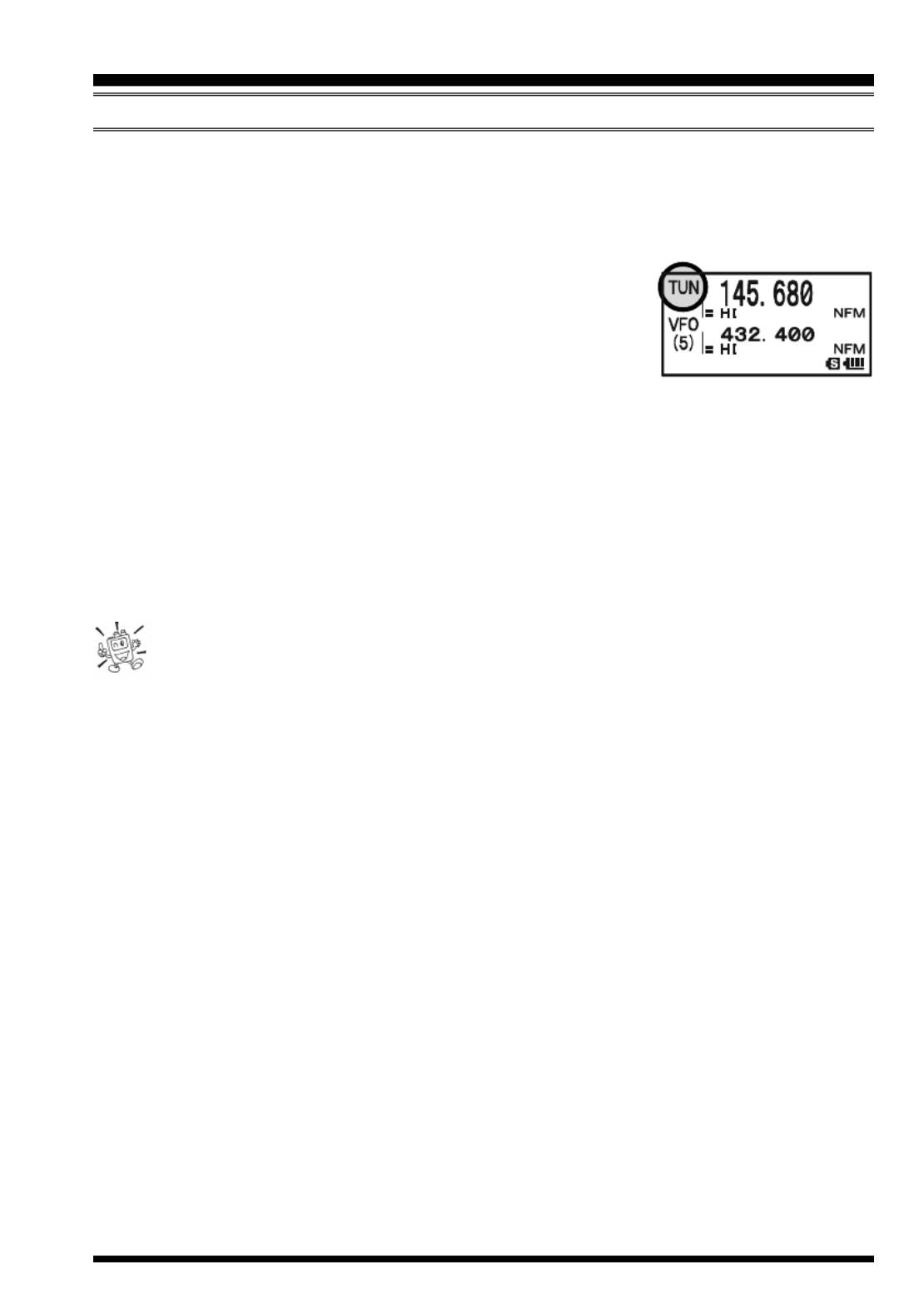
VX-8GR/GE OPERATING MANUAL 47
MEMORY OFFSET UNING T
Once you have recalled a particular memory channel, you may easily tune off that chan-
nel, as though you were in the “VFO” mode.
1. With the VX-8GR/GE in the Memory Recall (“MR”) mode, select the desired memory
channel.
2. Now press the f key, then press c key. The “MR” in-
dicator will be replaced by one which says “TUN” (“Memory
Tuning”).
3. Rotate the DIAL, as desired, to tune to a new frequency.
The synthesizer steps selected for VFO operation on the current band will be the steps
used during Memory Tuning.
4. If you wish to return to the original memory frequency, press c key briefly. The
“TUN” indicator will be replaced by “MR.”
5. If you wish to store a new frequency set during Memory Tuning, just press and hold
in the f key for one second, per normal memory storage procedure. The micropro-
cessor will automatically set itself to the next-available clear memory location, and
you then press the f key again, briefly to lock in the new frequency.
If you want to replace the original memory contents with the new frequency
settings, be sure to rotate the DIAL to the original memory channel number!
Any required CTCSS/DCS changes, or repeater offset modifications, must be done before
storing the data into the new (or original) memory channel location.
MEMORY MODE (REGULAR MEMORY CHANNEL OPERATION )

VX-8GR/GE OPERATING MANUAL48
MEMORY MODE (REGULAR MEMORY CHANNEL OPERATION )
MASKING MEMORIES
There may be situations where you want to “Mask” memories so they are not visible
during memory selection or scanning. For example, several memories used only in a city
you visit infrequently may be stored, then “Masked” until you visit that city, at which time
you can “Unmask” them for normal use (except for Memory Channel “1”).
1. Press the c key, if needed, to enter the Memory Recall (“MR”) mode.
2. Press and hold in the f key for 1/2 second, then rotate
the DIAL to select the memory channel to be “Masked”
from view.
3. Press the d key. The confirmation message (MASK?) will
appear on the display. Press the d key once more, the
display will revert to memory channel #1. If you rotate the
DIAL to the location you just “Masked,” you will observe
that it is now invisible.
4. To Unmask the hidden memory, repeat the above procedure: press and hold in the
f key for 1/2 second, rotate the DIAL to select the masked memory’s number, then
press the d key to restore the memory channel’s data.
Watch out! You can manually store data over a “Masked” memory, deleting
previous data, if you’re not careful. Use the “next available memory” stor-
age technique to avoid over-writing a masked memory.
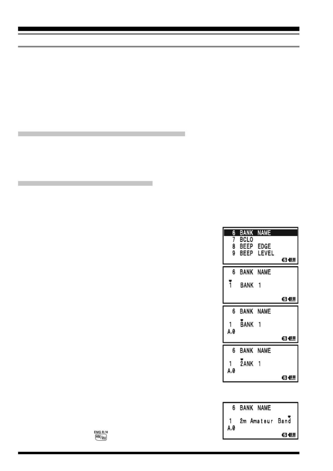
VX-8GR/GE OPERATING MANUAL50
MEMORY MODE (REGULAR MEMORY CHANNEL OPERATION )
5. To change to another Memory Bank, press the f key, then press the B key.
Now rotate the DIAL knob to select the new Memory Bank, then press the B key
again.
6. To exit from Memory Bank operation, just press the B key. The Memory Bank
number will be replaced by the “MR”, and you are now in the “regular” Memory
Recall mode, without utilization of the Memory Banks. The memories stored in the
various Banks will remain in those banks. You do not need to store them again.
R EMOVING MEMORIES FROM A MEMORY BANK
1. Recall the memory channel to be removed from a Memory Bank.
2. Press and hold the f key for 1/2 second, then press the d key to remove the
memory channel data from the Memory bank.
C HANGING A MEMOR Y BANK
’S NAME
You may change the default Memory Bank Names, which are shown on the display while
selecting the Memory Bank your desire.
1. Press and hold in the m key for one second to enter the Set Mode.
2. Rotate the DIAL knob to select the Set Mode Item 6: BANK
NAME.
3. Press the m key briefly to enable adjustment of this Set
Mode Item.
4. Rotate the DIAL knob to select the memory bank on which
you wish to change a label.
5. Press the M key briefly to enable changing of the name
tag. Press and hold the h key for two seconds to clear
any previous name, if desired.
6. Rotate the DIAL knob, or press one of the keyboard keys,
to select the first digit of the desired label.
Example 1: Rotate the DIAL knob to select any of the 61
available characters.
Example 2: Press the 2 key repeatedly to toggle among
the seven available characters associated with
that key: a b c 2 A B C
7. Press the M key to move to the next character, if needed.
8. Repeat steps 6 and 7 to program the remaining letters, num-
bers, or symbols of the desired label. A total of 16 charac-
ters may be used in the creation of a label.
9. Press and hold the key for two seconds to delete all
data after the cursor that may have been previously stored.
MEMORY BANK OPERATION
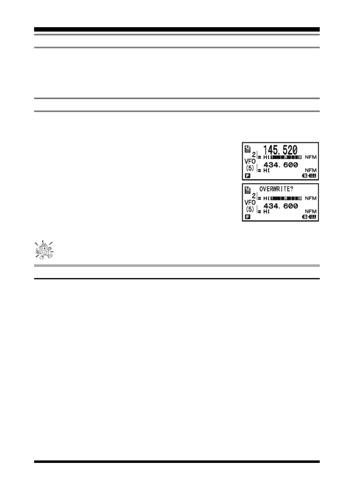
VX-8GR/GE OPERATING MANUAL 51
10. If you make a mistake, press the B key to backspace the cursor, then re-enter the
correct letter, number, or symbol.
11. When you have completed the changes of the label, press the PTT switch to save the
label and exit.
MOVING MEMORY DATA TO THE VFO
Data stored on memory channels can easily be moved to VFO, if you like.
1. Press the c key, if needed, to enter the Memory Recall (“MR”) mode.
2. Press and hold in the f key for 1/2 second, then rotate
the DIAL knob to select the memory channel containing the
frequency data to be moved to VFO.
3. Press the c key. The confirmation message (OVER-
WRITE?) will appear on the display. Press the c key once
more, the data will now have been copied to VFO, although
the original memory contents will remain intact on the pre-
viously stored channel. Press the PTT switch to cancel the
Moving Memory Data procedure, if desired.
If a Split Frequency Memory channel was transferred, the Tx frequency will be
ignored (you will be set up for Simplex operation on the Receive frequency).
MEMORY ONLY MODE
Once memory channel programming has been completed, you may place the radio in a
“Memory Only” mode, whereby VFO operation is impossible. This may be particularly
useful during public-service events where a number of operators may be using the radio
for the first time, and ultimate simplicity of channel selection is desired.
To place the radio into the Memory Only mode, turn the radio off. Now press and hold in
the c key while turning the radio on.
To return to normal operation, repeat the above power-on procedure.
MEMORY MODE (REGULAR MEMORY CHANNEL OPERATION )
MEMORY BANK OPERATION
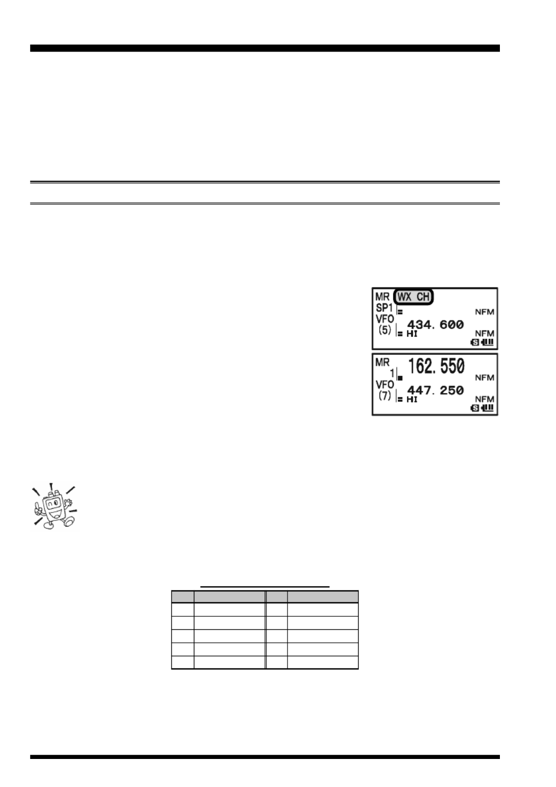
VX-8GR/GE OPERATING MANUAL52
MEMORY MODE (SPECIAL MEMORY CHANNEL OPERATION )
The VX-8GR/GE provides Special Memory Channels, which are made up of:
10 Weather Broadcast Channels.
57 VHF Marine Channels
1) The Special Memory Channels are only recalled on the “A-Band”
2) You may assign the Special Memory Channels to a Memory Bank. See page 49 re-
garding Memory Bank Operation for details.
WEATHER BROADCAST CHANNELS
The VHF Weather Broadcast Station Memory Channel Bank has been pre-programmed at
the factory, for quick selection of NOAA weather information stations.
1. Press the a key briefly to set the “A-Band” to the “Operating” band.
2. Press the f key, then press the 9 key, to recall the Special Memory Menu.
3. Press the B key, repeatedly if necessary to select the
“WX CH” (thus recalling the Weather Broadcast Memory
Bank).
4. Rotate the DIAL knob to select the desired Weather Broad-
cast channel.
5. If you wish to scan this bank to search for louder stations,
just press the PTT switch. When the scanner pauses on a
station, press the PTT switch once to halt the scan, or press
it twice to restart the scan.
6. To exit to normal operation, press the c key, or press f key followed by the 9
key.
In the event of extreme weather disturbances, such as storms and hurri-
canes, the NOAA (National Oceanic and Atmospheric Administration) sends
a weather alert accompanied by a 1050 Hz tone and subsequent weather
report on one of the NOAA weather channels. You may disable the Weather Alert tone
via Set Mode Item 100: WX ALERT, if desired. See page 147.
CH
1
2
3
4
5
CH
6
7
8
9
10
FREQUENCY
162.550 MHz
162.400 MHz
162.475 MHz
162.425 MHz
162.450 MHz
FREQUENCY
162.500 MHz
162.525 MHz
161.650 MHz
161.775 MHz
163.275 MHz
WX CHANNEL F LREQUENCY IST
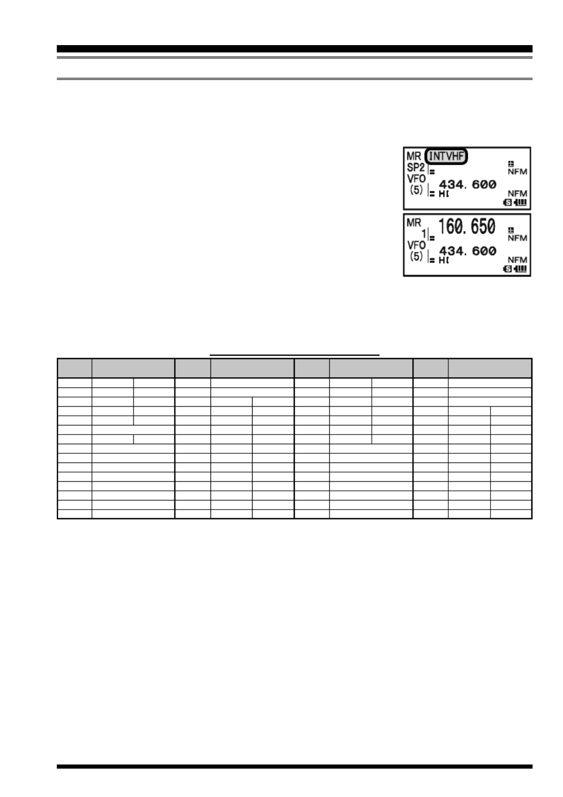
VX-8GR/GE OPERATING MANUAL 53
VHF MARINE MEMORY CHANNELS
The VHF Marine Channel Bank has been pre-programmed at the factory, for quick selec-
tion.
1. Press the a key briefly to set the “A-Band” to the “Operating” band.
2. Press the f key, then press the 9 key, to recall the Spe-
cial Memory Menu.
3. Press the B key, repeatedly if necessary to select the
“INTVHF” (thus recalling the VHF Marine Channel Bank).
4. Rotate the DIAL to select any of the 57 available VHF Ma-
rine Channels.
5. Press the h key to monitor the duplex frequency while
recalling a semi-duplex channel (such as Channel “1”). Press
the h key again to revert to simplex monitoring.
6. To exit to normal operation, press the c key, or press f key followed by the 9
key.
VHF MARINE CHANNEL F LREQUENCY IST
MEMORY MODE (SPECIAL MEMORY CHANNEL OPERATION )
CH
No.
1
2
3
4
5
6
7
8
9
10
11
12
13
14
15
CH
No.
60
61
62
63
64
65
66
67
68
69
70
71
72
73
74
CH
No.
16
17
18
19
20
21
22
23
24
25
26
27
28
CH
No.
75
76
77
78
79
80
81
82
83
84
85
86
87
88
FREQUENCY
(MHz)
156.050 160.650
156.100 160.700
156.150 160.750
156.200 160.800
156.250 160.850
156.300
156.350 160.950
156.400
156.450
156.500
156.550
156.600
156.650
156.700
156.750
FREQUENCY
(MHz)
156.800
156.850
156.900 161.500
156.950 161.550
157.000 161.600
157.050 161.650
157.100 161.700
157.150 161.750
157.200 161.800
157.250 161.850
157.300 161.900
157.350 161.950
157.400 162.000
FREQUENCY
(MHz)
156.025 160.625
156.075 160.675
156.125 160.725
156.175 160.775
156.225 160.825
156.275 160.875
156.325 160.925
156.375
156.425
156.475
156.525
156.575
156.625
156.675
156.725
FREQUENCY
(MHz)
156.775
156.825
156.875
156.925 161.525
156.975 161.575
157.025 161.625
157.075 161.675
157.125 161.725
157.175 161.775
157.225 161.825
157.275 161.875
157.325 161.925
157.375 161.975
157.425 162.025

VX-8GR/GE OPERATING MANUAL54
GENERAL
The VX-8GR/GE allows you to scan just the memory channels, the entire operating band,
or a portion of that band. It will halt on signals encountered, so you can talk to the station(s)
on that frequency, if you like.
Scanning operation is basically the same in each of the above modes. Before you begin,
take a moment to select the way in which you would like the scanner to resume scanning
after it halts on a signal.
S ETTING THE SCAN-RESUME TECHNIQUE
Three options for the Scan-Resume mode are available:
2.0sec - 10.0sec: In this mode, the scanner will halt on a signal it encounters, and will
hold there for the selected resume time. If you do not take action to
disable the scanner within that time period, the scanner will resume
even if the station is still active.
BUSY: In this mode, the scanner will halt on a signal it encounters. When the
carrier has dropped because the other station ceased transmission, the
scanner will resume. In the case of constant-carrier signals like Weather
Station broadcasts, the scanner will likely remain on this frequency
indefinitely. The Scan Re-start Delay time (default interval: 2 seconds)
is set by Set Mode Item 76: SCAN RE-START.
HOLD: In this mode, the scanner will halt on a signal it encounters. It will not
restart automatically; you must manually re-initiate scanning if you
wish to resume.
To set the Scan-Resume mode:
1. Press and hold the m key for one second to enter the Set Mode.
2. Rotate the DIAL knob to select Set Mode Item 77: SCAN
RESUME.
3. Press the m key briefly to enable adjustment of this Set
Mode Item.
4. Rotate the DIAL knob to select the desired scan-resume
mode.
5. Press the PTT switch to save the new setting and exit to
normal operation.
The default condition for this Set Mode Item is “5.0sec”.
SCANNING

VX-8GR/GE OPERATING MANUAL 55
SCANNING
To set the Scan-Restart Delay Time:
1. Press and hold the m key for one second to enter the Set Mode.
2. Rotate the DIAL knob to select Set Mode Item 76: SCAN
RE-START.
3. Press the m key briefly to enable adjustment of this Set
Mode Item.
4. Rotate the DIAL knob to select the desired Scan-Restart
Delay Time. Available selections are 0.1sec - 0.9sec
(0.1sec/step) and 1.0sec - 10.0sec (0.5sec/step).
5. Press the PTT switch to save the new setting and exit to
normal operation.
The default condition for this Set Mode Item is “2.0sec”.
GENERAL

VX-8GR/GE OPERATING MANUAL56
VFO SCANNING
This mode allows you to scan on the VFO mode.
1. Select the VFO mode by pressing the c key, if necessary.
2. Press and hold in the B key, then rotate the DIAL knob while holding in the
B key (the current bandwidth for the VFO scanner will
appear on the display) to select the bandwidth for the VFO
scanner. Available selections are ±1 MHz, , ±2 MHz ±5
MHz, BAND, ALL, and PMS-X.
±1 MHz ±2 MHz, , ±5 MHz: The scanner will sweep frequencies within the selected
bandwidth.
BAND: The scanner will sweep frequencies only on the cur-
rent band.
ALL: The scanner will sweep all frequencies between 108
MHz and 999.99 MHz.
PMS-X: The scanner will sweep frequencies within the cur-
rently-selected PMS frequency pair. See page 62 for
details.
3. Release the B key to start scanning.
4. When the scanner encounters a signal strong enough to open the squelch, the scanner
will halt temporarily; the decimal point of the frequency display will blink during this
“Pause” condition.
5. The scanner will then resume according to the Scan-Resume mode selected in the
previous section.
6. To cancel scanning, press the PTT switch or c key.
1) If you want to change direction of the scan while it is underway, rotate the
DIAL knob one click in the opposite direction. You’ll see the scanner turn
around and change frequency downward!
2) You may change the scanner’s method of operation so the VFO frequency will jump
to the low band edge of the next band when the VFO frequency reaches the high edge
of the current band (or vice versa). See page 146 regarding Set Mode Item 95: VFO
MODE.
SCANNING
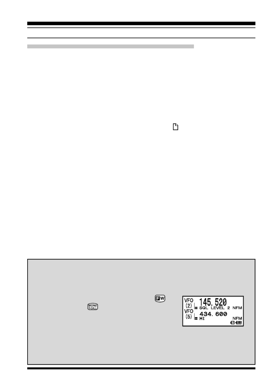
VX-8GR/GE OPERATING MANUAL 57
SCANNING
H OW TO SKIP (OMIT) A FREQUENCY DURING VFO SCAN
If the VFO scan stops on a frequency or frequencies that you do not need (such as a
spurious radiation from a television), such frequencies can be “skipped” during VFO scan-
ning. A special “Frequency Skip Memory” bank is reserved to store these frequencies.
To skip a frequency during VFO scanning:
1. While VFO scanning is stopped on the frequency that you do not need, press and hold
the f key for one second, then rotate the DIAL knob to select the desired Fre-
quency Skip Memory channel (900 999 - ). The microprocessor will automatically
select the next-available “free” Frequency Skip Memory channel (a memory register
on which no data has been stored). If you see the “ ” icon at the upper left of the
channel number, it means that the channel currently has no data written on it (i.e. the
channel is “free”).
2. Press the f key to store the frequency into the Frequency Skip Memory. It will now
be ignored during VFO scanning.
To re-institute a frequency into the VFO scan loop:
1. Press the c key, if needed, to enter the Memory Recall (“MR”) mode.
2. Press and hold in the f key for one second, then rotate the DIAL knob to select the
memory channel to be re-instituted.
3. Press the d key. The confirmation message (DELETE?) will appear on the display.
Press the d key once more to delete the channel from the Frequency Skip Memory;
this will restore the frequency into the VFO scan loop.
The VX-8GR/GE has 100 VFO Frequency Skip Memory Channels.
VFO SCANNING
S ETTING THE SQUELCH LEVEL DURING ACTIVE SCANNING OPERATION
The VX-8GR allows adjustment of the Squelch level “on the fly” while you are
scanning.
1. While the scanner is engaged, press the key,
then press the key (the current squelch level
will appear below the frequency display).
2. Rotate the DIAL to select the desired Squelch level.
3. Press the PTT switch briefly to save the new setting and exit to normal op-
eration. In this case, pressing the PTT switch this one time will not causing
scanning to stop.

VX-8GR/GE OPERATING MANUAL58
SCANNING
MEMORY SCANNING
Memory scanning is also easy to initiate:
1. Set the radio to the Memory Recall (“MR”) mode by pressing the c key, if neces-
sary.
2. Press and hold in the B key, then rotate the DIAL knob while holding in the
B key (the current Memory Scan mode will appear on
the frequency display) to select the desired Memory Scan
mode. Available selections are ALL CH, TAG1, TAG2, BAND,
and PMS-X.
ALL CH: The scanner sweeps all Memory channels.
TAG1: The scanner sweeps only those Memory channels with the same first digit of
the alpha/numeric tag as the first channel on which scanning started.
TAG2: The scanner sweeps only those Memory channels with the same first and
second digits of the alpha/numeric tag as the first channel on which scan-
ning started.
BAND: The scanner sweeps only those Memory channels which are memorized on
the same operating band as the first channel on which scanning started.
PMS-X: The scanner will sweep frequencies within the currently-selected PMS fre-
quency pair. See page 62 for details.
3. Release the B key to start scanning.
4. As with VFO scanning, the scanner will halt on any signal encountered that is strong
enough to open the squelch; it will then resume scanning according to the Scan-Re-
sume mode set previously. When there are no memory channels corresponding to the
selected Memory Scan mode, the “MS ERR” notation will appear on the display.
5. To cancel scanning, press the PTT switch or c key.

VX-8GR/GE OPERATING MANUAL 59
H OW TO SKIP (OMIT) A C DHANNEL URING MEMORY SCAN
As mentioned previously, some continuous-carrier stations like a Weather Broadcast sta-
tion will seriously impede scanner operation if you are using the “Carrier Drop” Scan-
Resume mode, as the incoming signal will not pause long enough for the transceiver to
resume scanning. Such channels may be “Skipped” during scanning, if you like:
1. Recall the Memory Channel to be skipped during scanning.
2. Press the f key, then press the 5 key. The small “”
icon will appear at the left of the frequency display. The
current Memory Channel will now be ignored (skipped) dur-
ing scanning (the “skipped” channel will, of course, still be
accessible via manual channel selection methods using the DIAL knob in the Memory
Recall (“MR”) mode, whether or not it is locked out of the scanning loop).
To re-institute a channel into the scanning loop, press the f key followed by the 5
key twice, to remove the small “” icon from the display.
Note: You may notice a blinking “” icon while you perform above procedure. It indi-
cates the “Preferential Memory Scan” channel, described in the next column.
PREFERENTIAL MEMORY SCAN
The VX-8GR/GE also allows you to set up a “Preferential Scan List” of channels which
you can “flag” within the memory system. These channels are designated by a blinking
“” icon when you have selected them, one by one, for the Preferential Scan List. When
you initiate memory scanning on a channel with the blinking “” icon appended, only
those channels bearing the blinking “” icon will be scanned. If you initiate scanning on
a channel which does not have the blinking “” icon appended, you will scan all channels
including those with the blinking “” icon appended.
Here is the procedure for setting up and using the Preferential Scan List:
1. Recall the Memory Channel which you wish to add to the Preferential Scan List.
2. Press the f key followed by the 5 key until a blinking
small “” icon appears at the left of the frequency display.
To clear the memory channel from the “Preferential Scan List”,
press the f key followed by the 5 key. The blinking small
“” icon will disappear from the display.
SCANNING
MEMORY SCANNING

VX-8GR/GE OPERATING MANUAL60
To initiate Preferential Memory Scan:
1. Press the c key briefly to enter the Memory Recall (“MR”) mode, if you are not
using memories already.
2. Rotate the DIAL knob to select any channel which has a
blinking “” icon appended to the channel number.
3. Press and hold in the B key, then rotate the DIAL knob
while holding in the Bkey (the current Memory Scan
mode will appear on the frequency display) to select the
desired Memory Scan mode. Available selections are ALL
CH(ONLY), TAG1(ONLY), TAG2(ONLY), BAND(ONLY), and
PMS-X.
ALL CH: The scanner sweeps all Preferential Scan Channels.
TAG1: The scanner sweeps only those Preferential Scan Channels with the same
first digit of the alpha/numeric tag as the first channel on which scanning
started.
TAG2: The scanner sweeps only those Preferential Scan Channels with the same
first and second digits of the alpha/numeric tag as the first channel on which
scanning started.
BAND: The scanner sweeps only those Preferential Scan Channels which are memo-
rized on the same operating band as the first channel on which scanning
started.
PMS-X: The scanner will sweep frequencies within the currently-selected PMS fre-
quency pair. This is not a Preferential Memory Scan, see page 62 for details.
4. Release the B key to start scanning.
When there are no memory channels corresponding to the selected Memory Scan
mode, the “MS ERR” notation will appear on the display.
5. To cancel scanning, press the PTT switch or c key.
MEMORY SCANNING
SCANNING
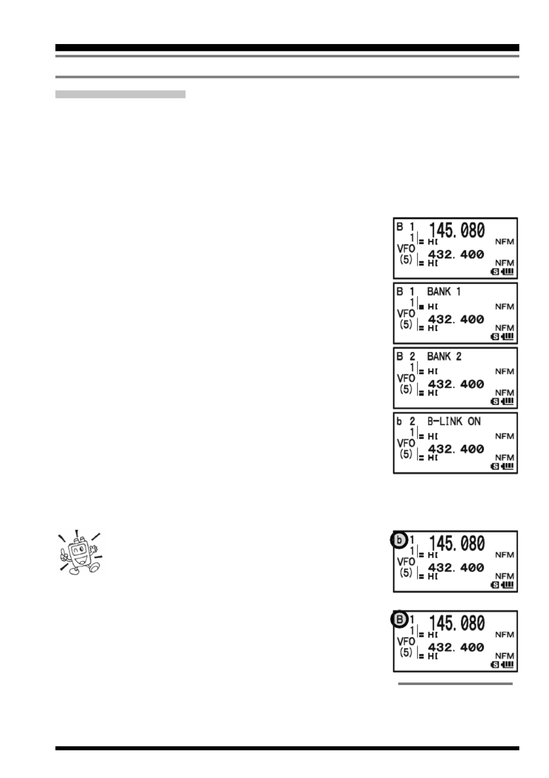
VX-8GR/GE OPERATING MANUAL 61
MEMORY BANK CAN S
When the Memory Bank feature is engaged, the scanner sweeps only memory channels in
the current Memory Bank. However, if the Memory Bank Link Scan feature is enabled,
you may sweep the memory channels in several Memory Banks which you have selected.
To enable the Memory Bank Link Scan feature:
1. Set the radio to the Memory Recall (“MR”) mode by pressing the c key, if neces-
sary.
2. Press the B key to activate the “Memory Bank” mode.
The “MR” indicator will be replaced by one of the Memory
Bank numbers (“B 1” through “B24”).
3. Press the f key followed by the B key. The Memory
Bank number will begin to blink.
4. Rotate the DIAL knob to select the first Memory Bank
(“BANK 1” ~ “BANK24”) you wish to sweep using Memory
Bank Link Scan.
5. Press the c key briefly. A “B-LINK ON” notation will ap-
pear for two seconds on the display, indicating this Memory
Bank will now be swept during Memory Bank Scan.
6. Repeat steps 4 and 5 above, to append the “B-LINK ON”
notation to any other Memory Banks you wish to sweep.
7. Press the B key.
8. Now, press and hold in the B key for one second to
initiate the Memory Bank Link Scan.
9. To remove a Memory Bank from the Memory Bank Link Scan, repeat steps 1 - 5
above, to change the “B-LINK ON” notation into “B-LINK OFF”.
1) When the Memory Bank is enabled for Memory
Bank scan, the Memory Bank number (“B x”) in-
dication turns into “bx” (capital “B” turns into
small “b”).
2) You may enable/disable the Memory Bank scan via Set Mode
Item 5: BANK LINK.
MEMORY SCANNING
SCANNING
M ”EMORY BANK SCAN “DISABLED

VX-8GR/GE OPERATING MANUAL62
P ROGRAMMABLE (BAND LIMIT) MEMORY SCAN (PMS)
This feature allows you to set sub-band limits for either scanning or manual VFO opera-
tion. For example, you might wish to set up a limit (in North America) of 144.300 MHz to
148.000 MHz to prevent encroachment into the SSB/CW “Weak Signal” portion of the
band below 144.300 MHz. Here’s how to do this:
1. Set the radio to the VFO mode by pressing the c key, if necessary.
2. Using the techniques learned earlier, store (as in the above example) 144.300 MHz
into Memory Channel #L1 (the “L” designates the Lower sub-band limit).
3. Likewise, store 148.000 MHz into Memory Channel #U1 (the “U” designates the
Upper sub-band limit).
4. Press and hold in the B key for one second and rotate
the DIAL knob while holding in the B key to select the
desired PMS frequency pair (PMSxx).
5. Release the B key to start scanning within the just-pro-
grammed range. The “VFO” label will be replaced by “PMS”
and the Band number will be replaced by “Pxx”. Tuning
and scanning will now be limited within the just-pro-
grammed range.
6. 50 pairs of Band Limit memories, labeled L1 U1/ through L50 U50/ are available.
You therefore can set upper and lower operation limits on a number of bands, if you
like.
7. To exit to normal operation, press the c key.
SCANNING

VX-8GR/GE OPERATING MANUAL 63
“PRIORITY CHANNEL” SCANNING (DUAL WATCH)
The VX-8GR/GE’s scanning features include a two-channel scanning capability which
allows you to operate on a VFO or Memory channel, while periodically checking a user
defined Memory Channel for activity. If a station is received on the Memory Channel
which is strong enough to open the Squelch, the scanner will pause on that station in
accordance with the Scan-Resume mode set via Menu Item 77: SCAN RESUME. See
page 54.
Here is the procedure for activating Priority Channel Dual Watch operation:
1. Press the c key briefly to enter the Memory Recall (“MR”) mode, if you are not
using memories already.
2. Press and hold in the f key for one second, then rotate the DIAL knob to select the
memory channel you wish to be the “Priority” channel.
3. Press the B key. The “P” icon will appear to the right of
the “MR” label, indicating it is the Priority channel.
4. Now set the VX-8GR/GE for operation on another memory
channel, or on a VFO frequency.
5. Press and hold in the c key for one second. The display
will remain on the VFO or memory channel selected. How-
ever, every five seconds the VX-8GR/GE will check the
Priority Channel for activity. The “MR” label will be re-
placed by “MDW” while operating on the Memory channel or the “VFO” label will be
replaced by “VDW” while operating on the VFO mode.
6. If a station appears on the Priority Channel, the radio will pause on that channel, as
described previously.
The receiving time interval (ratio) between the current channel (or VFO frequency) and
Priority channel may be customized via Set Mode Item 67: PRI TIME.
To set the receiving time interval:
1. Press and hold the m key for one second to enter the Set Mode.
2. Rotate the DIAL knob to select Set Mode Item 67: PRI TIME.
3. Press the m key briefly to enable adjustment of this Set
Mode Item.
4. Rotate the DIAL knob to select the desired time interval.
Available selections are 0.1sec - 0.9sec (0.1sec/step) and
1.0sec - 10.0sec (0.5sec/step).
5. Press the PTT switch briefly to save the new setting and
exit to normal operation.
The default condition for this Set Mode Item is “5.0sec”.
SCANNING

VX-8GR/GE OPERATING MANUAL64
P RRIORITY EVERT MODE
During Priority channel operation (Dual Watch), a special feature is available which will
allow you to move to the Priority Channel instantly, without waiting for activity to appear
on the Priority Channel.
When this feature is enabled, and priority monitoring is engaged, just press the microphone’s
PTT switch. Operation will instantly revert to the Priority Channel.
To enable Priority Revert operation:
1. Press and hold the m key for one second to enter the Set Mode.
2. Rotate the DIAL knob to select Set Mode Item 66: PRI RE-
VERT.
3. Press the m key briefly to enable adjustment of this Set
Mode Item.
4. Rotate the DIAL knob to select “ON”.
5. Press the PTT switch briefly to save the new setting and
exit to normal operation.
To disable Priority Revert operation, select “OFF” in step 4 above.
“PRIORITY CHANNEL” SCANNING (DUAL WATCH )
SCANNING

VX-8GR/GE OPERATING MANUAL 65
AUTOMATIC LAMP ILLUMINATION ON SCAN STOP
The VX-8GR/GE will automatically illuminate the LCD Lamp whenever the scanner
stops on a signal; this allows you to see the frequency of the incoming signal better at
night. Note that this will, of course, increase battery consumption, so be sure to switch it
off during the day (the default condition for this feature is “ON”).
The procedure for disabling the Scan Lamp is:
1. Press and hold the m key for one second to enter the Set Mode.
2. Rotate the DIAL knob to select Set Mode Item 75: SCAN
LAMP.
3. Press the m key briefly to enable adjustment of this Set
Mode Item.
4. Rotate the DIAL knob to select “OFF”.
5. Press the PTT switch briefly to save the new setting and
exit to normal operation.
B EAND DGE BEEPER
The VX-8GR/GE will automatically “beep” when a band edge is encountered during
scanning (either in standard VFO scanning or during PMS operation). You may enable
this feature (band edge beeper) when the frequency reaches the band edge while selecting
the VFO frequency using the DIAL knob.
The procedure for enabling the Band-Edge Beeper is:
1. Press and hold the m key for one second to enter the Set Mode.
2. Rotate the DIAL knob to select Set Mode Item 8: BEEP
EDGE.
3. Press the m key briefly to enable adjustment of this Set
Mode Item.
4. Rotate the DIAL knob to select “ON”.
5. Press the PTT switch briefly to save the new setting and
exit to normal operation.
SCANNING

VX-8GR/GE OPERATING MANUAL66
The VX-8GR/GE allows the display of your position (Longitude/Latitude) with the built-
in GPS Antenna Unit.
1. Press the m key until the GPS screen appears.
2. Press and hold in the m key for one second to enter the APRS/GPS Set Mode.
3. Rotate the DIAL knob to select Set Mode Item 18: GPS POWER.
4. Press the m key briefly to enable selection of this Set Mode Item.
5. Rotate the DIAL knob to select “GPS ON” (to activate the built-in GPS Antenna
Unit).
6. Press the PTT switch briefly to save the new setting and exit to normal operation.
7. When the transceiver succeeds in receiving a valid GPS
signal, your current position (Longitude/Latitude), current
time (UTC), and altitude will appear on the display. Rotate
the DIAL knob (or press the a b/ key) to scroll through
additional lines of station text on the display.
The received satellite number appears at the lower right of
compasses (In the example at the right, it is 4 satellites).
When receiving a signal from more than 3 satellites, the
“ ” icon will appear on the display.
Advice: 1) When the built-in GPS Antenna Unit is first turned on, it may take several
minutes to compute a fix of your position. This is normal, as the built-in GPS unit is
downloading “almanac” information from the GPS satellites.
2) While the VX-8GR/GE searches for a GPS signal, the compass icon does not
appear on the display and the position information (Longitude/Latitude) blinks on the
display.
3) If the VX-8GR/GE does not receive a valid GPS signal after three minutes have
passed, you may be in a poor location for satellite reception, such as inside of a house
or building; try moving to a less obstructed position.
8. If you walk a few meters from your current location, your course direction is dis-
played on the compass of the display and walking speed is displayed in the “SPD”
column of the display.
9. Press the M key to toggle the GPS screen between “North
Up” and “Heading Up”. The course direction displays a
black arrow in the “North Up” screen, and displays a white
arrow and small “H” icon in the “Heading Up” screen.
10. To return to normal operation, press the m key several
times until the normal screen appears.
1) When the VX-8GR/GE GPS signal is interrupted;
such as when you enter into a tunnel, the compass icon
disappears from the display but maintains the position
information (Longitude/Latitude) at the point where the GPS sig-
GPS OPERATION
“NORTH UP”
“HEADING UP”

VX-8GR/GE OPERATING MANUAL 67
nal was lost.
2) When the built-in GPS Antenna Unit is activated, the current consumption increases
approximately 40 mA. Therefore, battery life is reduced by approximately 20 % when
the built-in GPS Antenna Unit is activated.
3) You may memorize your current position as plotted by the GPS (up to ten points can be
saved) via the APRS/GPS Set Mode Item 23: MY POSITION. See page 157 for details.
You may customize the Time Zone (Time Offset), Display Units of the GPS screen, and
GPS Datum for your own operating requirements via the APRS/GPS Set Mode.
S ETTING THE T ZIME ONE (TIME OFFSET )
Sets the time offset between your local time and UTC (Universal Time Coordinated or
GMT: Greenwich Mean Time) shown on the display.
1. Press the m key several times until the GPS screen ap-
pears on the display.
2. Press and hold the m key for one second to enter the
APRS/GPS Set Mode.
3. Rotate the DIAL knob to select Set Mode Item 27: TIME
ZONE.
4. Press the m key briefly to enable selection of this Set
Mode Item.
5. Rotate the DIAL knob to select the time offset from UTC.
See illustration below to find your offset time from UTC. If
“UTC +0:00” is assigned, the time is the same as UTC.
6. Press the PTT switch briefly to save the new setting and
exit from the APRS/GPS Set Mode.
GPS OPERATION

VX-8GR/GE OPERATING MANUAL68
S DELECTING THE ISPLAY UNITS OF THE GPS SCREEN
1. Press the m key until the GPS screen appears.
2. Press and hold the m key for one second to enter the
APRS/GPS Set Mode.
3. Rotate the DIAL knob to select Set Mode Item 20: GPS
UNIT.
4. Press the m key briefly to enable adjustment of this Set
Mode Item.
5. Rotate the DIAL knob to select the preferred unit for “Posi-
tion” (.MMM’ or ’SS”).
6. Press the b key to change the cursor to “ ”, thenSpeed
rotate the DIAL knob to select the preferred unit (km/h, mph,
or knot).
7. Press the b key to change the cursor to “Altitude”, then rotate the DIAL knob to
select the preferred unit (m or ft).
8. Press the PTT switch briefly to save the new setting and exit from the APRS/GPS Set
Mode.
S ELECTING THE MAP DATUM
While most operations (including APRS ® operation) will utilize the default “WGS84”
database of locations, you may use a different database.
1. Press the m key until the GPS screen appears.
2. Press and hold the m key for one second to enter the
APRS/GPS Set Mode.
3. Rotate the DIAL knob to select Set Mode Item 17: GPS
DATUM.
4. Press the m key briefly to enable adjustment of this Set
Mode Item.
5. Rotate the DIAL knob to select the database you wish to
use. Available selections are WGS-84, Tokyo Mean, Tokyo
Japan, Tokyo Korea, and Tokyo Okinawa.
6. Press the PTT switch briefly to save the new setting and
exit from the APRS/GPS Set Mode.
Do not change the Map Datum while the GPS/APRS (described in the next
chapter) is in operation. The position indication will be incorrect.
GPS OPERATION

VX-8GR/GE OPERATING MANUAL 69
NOTE

VX-8GR/GE OPERATING MANUAL 71
13. Rotate the DIAL knob to select the desired one of the three
preset icons. To choose another icon, press the B key,
then rotate the DIAL knob to select the desired symbol after
having selected the preset icon. When you have completed
selecting the icon, press the B key again. You may
choose 1 of 46 different symbols.
14. Press the m key briefly to save the new setting.
15. Rotate the DIAL knob to select Set Mode Item 25: POSI-
TION COMMENT.
16. Press the m key briefly to enable adjustment of this Set
Mode Item.
17. Rotate the DIAL knob to select the desired comment.
18. Press the m key briefly to save the new setting.
19. Rotate the DIAL knob to select Set Mode Item 23: MY
POSITION.
20. Press the m key briefly to enable adjustment of this Set
Mode Item.
21. If you enter your position (Longitude/Latitude) manually
without using the built-in GPS receiver, perform the fol-
lowing procedures. Otherwise, select “GPS” by rotating the
DIAL knob and advance to step 22.
APRS ® OPERATION
PREPARATIONS
SSID
Non
-1
-2
-3
-4
-5
-6
-7
-8
-9
-10
-11
-12
-13
-14
-15
DETAILS
Home Station, Home Station IGate
Digipeater
Digipeater
Digipeater
HF to VHF Gateway
IGate (not Home Station)
Operation via Satellite
Hand-held Transceiver, such as VX-8GR
Maritime Mobile
Mobile Transceiver, such as FTM-350R
Operation via Internet
APRS touch-tone User (and the Occasional Balloons)
Portable Units, such as Laptops, Camp Sites etc.
Not Used
Trackers
HF Operation
SSID LIST
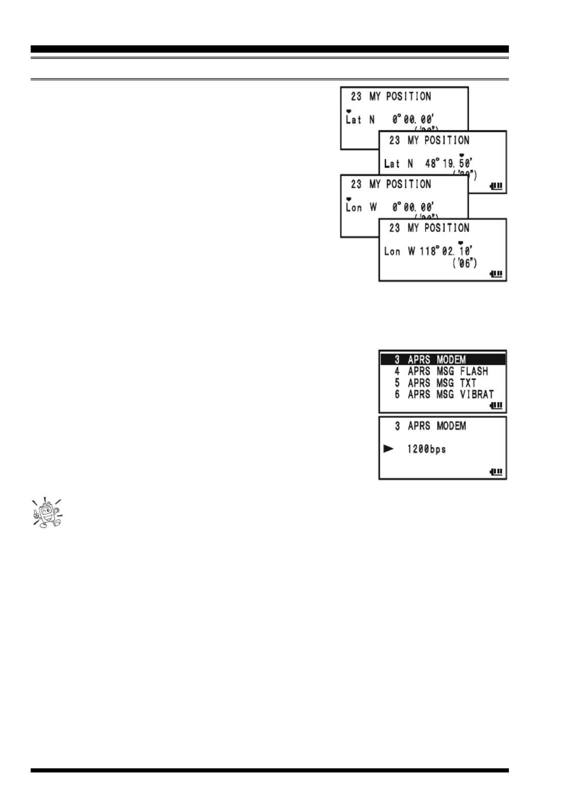
VX-8GR/GE OPERATING MANUAL72
1) Select “Lat” by rotating the DIAL knob.
2) Press the M key to enable entering of your
latitude using the Decimal system.
3) Use the B and M keys to navigate to the
individual columns and then use the DIAL knob to se-
lect the desired numbers in each column. Re-
peat for each column to complete your latitude
entry.
4) Move the cursor to “Lat” using the B M/
key and then rotate the DIAL knob one click clockwise to
select “Lon”. Enter your longitude using the same proce-
dure as described above, then advance to the next step.
Note: The sexagesimal value that is shown in parentheses is automatically converted
from the decimal value.
22. Press the m key briefly to save the new setting.
23. Rotate the DIAL knob to select Set Mode Item 3: APRS
MODEM.
24. Press the M key briefly to enable adjustment of this Set
Mode Item.
25. Rotate the DIAL knob to select “1200bps” (to activate the
AX.25 modem).
26. Press the PTT switch briefly to save the new setting and
exit from the APRS/GPS Set Mode.
You may memorize your current location as plotted by the GPS (up to ten loca-
tions can be saved). See page 157 for details.
The VX-8GR/GE provides many convenient functions for APRS operation. Refer to the
“APRS/GPS Set Mode” chapter beginning with page 148 for details.
APRS ® OPERATION
PREPARATIONS

VX-8GR/GE OPERATING MANUAL74
Deleting a Received Beacon from the “STATION LIST”
1. Press the m key several times until the STATION LIST
screen appears on the display.
2. Rotate the DIAL knob (or press the a b/ keys) to se-
lect the beacon station to be deleted.
3. Press the c key. The confirmation message (DELETE?)
will appear on the display. Press the c key once more,
the selected beacon station will be deleted from the STA-
TION LIST.
APRS ® OPERATION
R ECEIVING AN APRS BEACON
EMERGENCY COMMENT Set
x 3 times
EMERGENCY COMMENT Received
x 12 times
BEACON Received (@Filter “ON”)
BEACON Received (@Filter “OFF”)
OWN BEACON (MY POSITION ) Received
APRS ALERT BEEP LIST
MESSAGE Received
GROUP/BULLETIN MESSAGE Received
MESSAGE ACK Received
MESSAGE REJ Received
: You may select your constructed user
melody as the APRS Alert Beep via GPS/
APRS Set Mode Item 8: APRS RINGER
MSG. See page 152 for details.
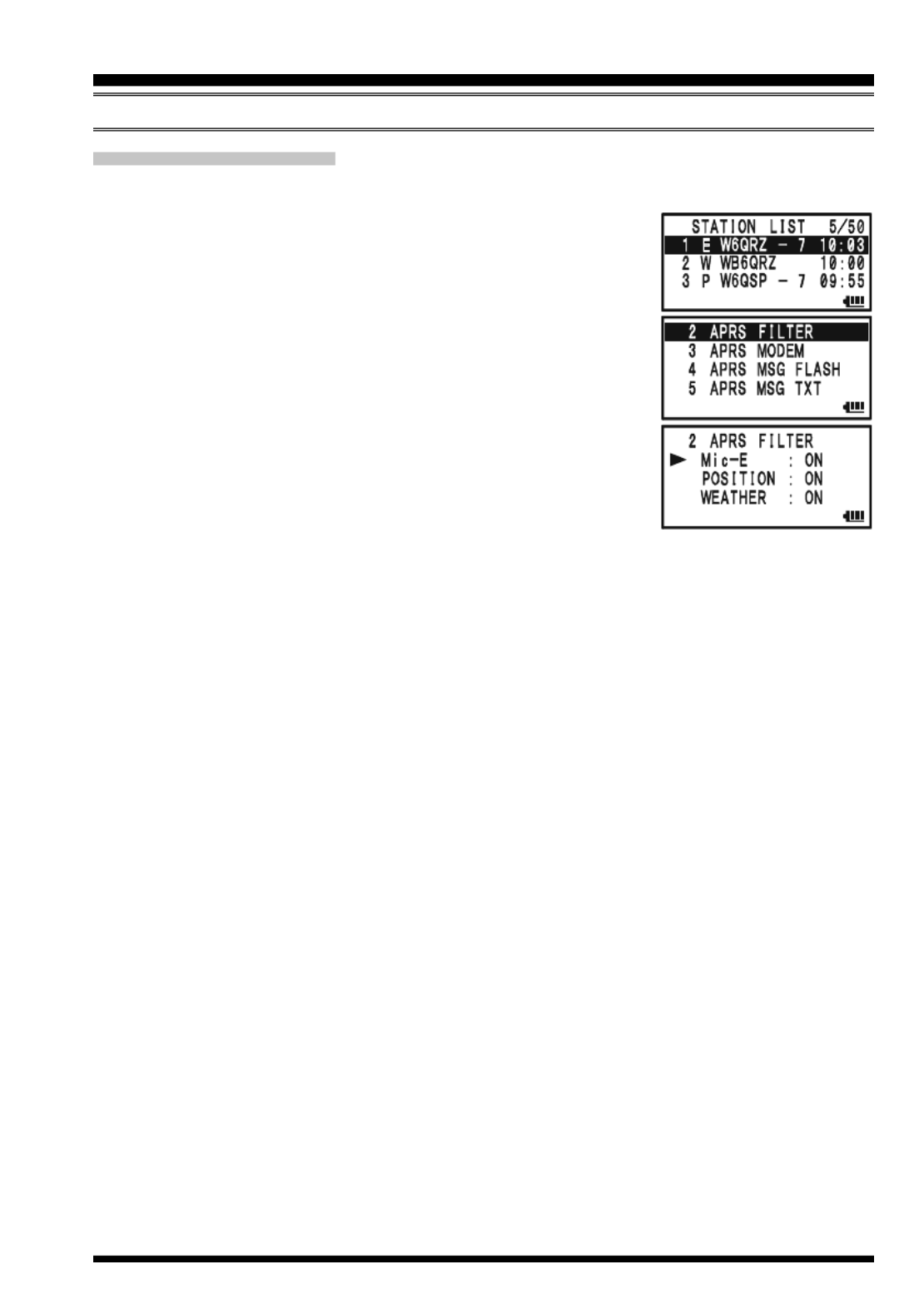
VX-8GR/GE OPERATING MANUAL 75
APRS FILTER SETTING
The APRS filter option allows you to receive only specified types of data.
1. Press the m key several times until the STATION LIST
screen appears on the display.
2. Press and hold the m key for one second to enter the
APRS/GPS Set Mode.
3. Rotate the DIAL knob to select Set Mode Item 2: APRS
FILTER.
4. Press the m key briefly to enable adjustment of this Set
Mode Item.
5. Press the a b/ key to select the “Filter” you wish to
exclude, then rotate the DIAL knob to select “OFF”.
6. Repeat above steps and select “OFF” to any other filters you
wish to exclude.
7. When you have completed your selection, press the PTT switch to save the new
setting and exit to the STATION LIST screen.
APRS ® OPERATION
R ECEIVING AN APRS BEACON

VX-8GR/GE OPERATING MANUAL76
APRS ® OPERATION
T RANSMIT AN APRS BEACON
To transmit your APRS Beacon, just press the d key.
The VX-8GR/GE allows you to transmit your APRS Beacon automatically and repeat-
edly via the APRS/GPS Set Mode.
1. Press the m key several times until the STATION LIST
screen appears on the display.
2. Press and hold the m key for one second to enter the
APRS/GPS Set Mode.
3. Rotate the DIAL knob to select Set Mode Item 14: BEA-
CON TX.
4. Press the m key briefly to enable adjustment of this Set
Mode Item.
5. Rotate the DIAL knob to select the desired “Auto” beacon
mode.
MANUAL: Disable Automatic Transmission.
AUTO: Enable Automatic Transmission.
Transmits your APRS beacon in accordance with the interval determined
by Set Mode Item 12: BEACON INTERVAL.
SMART: Enable Automatic Transmission.
Transmits your APRS beacon in accordance with the interval determined by
Set Mode Item 26: SmartBeaconing. This selection does not appear unless
Set Mode Item 26: SmartBeaconing is activated. See page 158 for details.
6. Press the m key briefly, then rotate the DIAL knob
to select Set Mode Item 12: BEACON INTERVAL.
7. Press the m key briefly to enable adjustment of
this Set Mode Item.
8. Rotate the DIAL knob to select the desired interval time.
9. Press the PTT switch to save the new setting and exit to the
STATION LIST screen.
When the APRS Beacon mode is set to “AUTO”, the “
” icon
will appear at the upper left corner of the display. Similarly,
when the APRS Beacon mode is set to “SMART”, the “
”
icon will appear at the upper left corner of the display.
1) You may toggle the APRS Beacon mode between “MANUAL”, “AUTO”,
and “SMART” by pressing the M key.
2) When the APRS frequency is busy (Squelch is opened), the VX-8GR/GE
will not transmit an APRS Beacon in manual or automatic modes. Insure that the squelch
is closed.

VX-8GR/GE OPERATING MANUAL 77
You may store five Status Text Messages (up to the 60 characters for each memory), and
you may transmit one of these Status Text Messages with the APRS Beacon.
1. Press the m key several times until the STATION LIST
screen appears on the display.
2. Press and hold the m key for one second to enter the
APRS/GPS Set Mode.
3. Rotate the DIAL knob to select Set Mode Item 13: BEA-
CON STATS TXT.
4. Press the m key briefly to enable adjustment of this Set
Mode Item.
5. Rotate the DIAL knob to select the Status Text register
(1 - 5) you wish to store data to.
6. Press the M key briefly to begin comment entry into the
selected resister.
7. Rotate the DIAL knob (or press the keyboard) to select the
first character of the comment.
8. Press the M key to move to the next character.
9. Repeat steps 6 and 7 to program the remainder of the com-
ment.
10. If you make a mistake, press the B key to back-space the cursor, then re-enter the
correct character.
11. You may add/delete a character to a comment using the following technique.
1) If you want to clear any previous comments, press the a b/ key to select the
“ALL CLEAR” then press the c key.
2) If you want to delete a previously-stored comment after the cursor, press the
a b c/ key to select “CLEAR” then press the key.
3) If you want to add a character, press the a b/ key to select “INSERT” then
press the c key.
Note: Some transceivers cannot receive the full 60-character message. We recom-
mend that you make the message as short as possible.
12. When you have completed your entry, press the PTT switch to save the new setting
and exit to the STATION LIST screen.
APRS ® OPERATION
T RANSMIT AN APRS BEACON
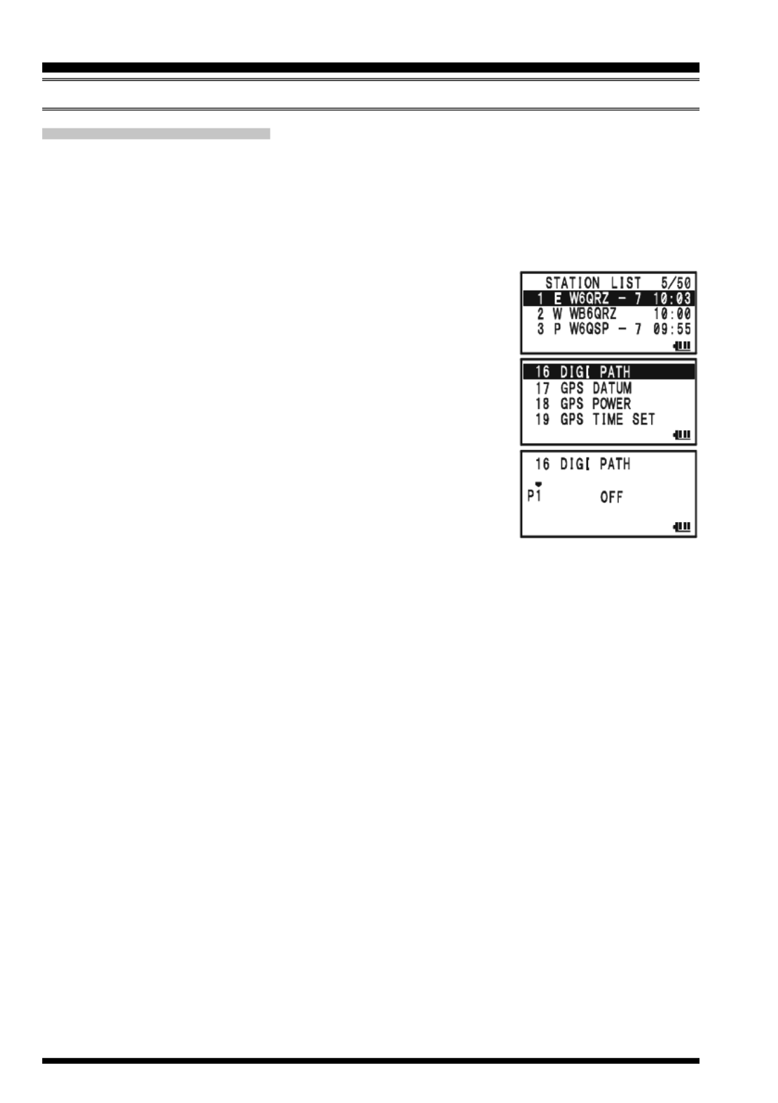
VX-8GR/GE OPERATING MANUAL78
T RANSMIT AN APRS BEACON
DIGIPEATER PATH SETTING
The VX-8GR/GE allows you to set up to eight digipeaters for the APRS Packet Path.
The VX-8GR/GE is preset to “WIDE1-1” and “WIDE1-1, WIDE2-1” digi-path to insure
that your transmitted APRS Beacon is repeated by the new-N paradigm digipeaters. We
recommend that you use this setting by default.
1. Press the m key several times until the STATION LIST
screen appears on the display.
2. Press and hold the m key for one second to enter the
APRS/GPS Set Mode.
3. Rotate the DIAL knob to select Set Mode Item 16: DIGI
PATH.
4. Press the m key briefly to enable adjustment of this Set
Mode Item.
5. Rotate the DIAL knob to select the Pass Number (P1 - P8)
you wish to set.
6. Press the M key briefly to begin callsign entry into the
selected path.
7. Rotate the DIAL knob (or press the keyboard) to select the first character of the callsign
(with SSID) of the digipeater.
8. Press the M key to move to the next character.
9. Repeats steps 7 and 8 to program the remainder of the callsign.
10. If you make a mistake, press the B key to backspace the cursor, then re-enter the
correct character.
11. When you have completed your entry, press the PTT switch to save the new setting
and exit to the STATION LIST screen.
APRS® OPERATION
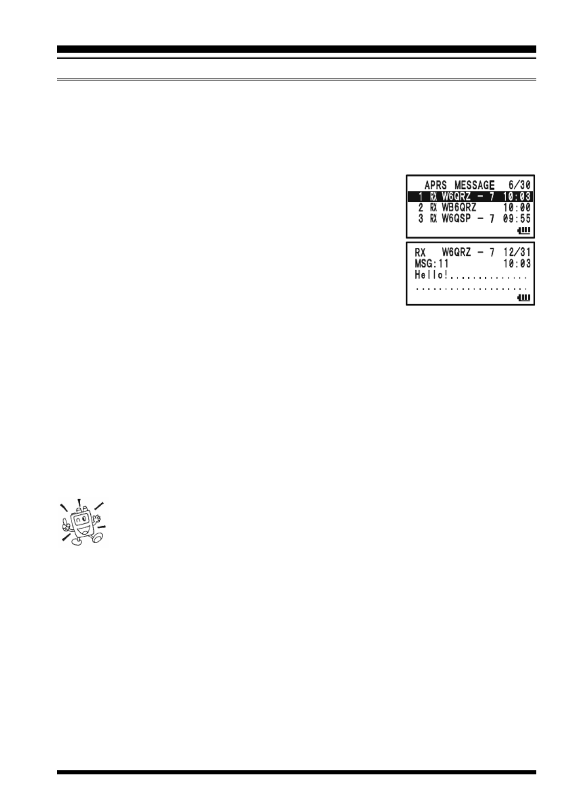
VX-8GR/GE OPERATING MANUAL 79
R ECEIVING AN APRS MESSAGE
1. Set the “B-Band” to the APRS frequency. 144.390 MHz is generally used in North
America. If you don’t know the APRS frequency for your country, ask your dealer.
The AX.25 modem is not activated in the “A-Band”.
2. When an APRS message is received, the alert beep will sound and the white LED will
blink.
3. Press the m key several times until the APRS MESSAGE
screen appears on the display.
The APRS MESSAGE screen stores up to 30 messages.
The messages are sorted according to the time the station
message is received. The latest message is stored into the
first message slot (First-in, First-out format).
4. To confirm the received message, rotate the DIAL knob (or
press the a/b keys) to select the desired message, then
press the B key.
Note: You may jump to the top of the “APRS MESSAGE LIST” by pressing the 1
key.
5. Rotate the DIAL knob (or press the a b/ keys) to scroll through additional lines
or pages of the received stations message.
Note: You may confirm additional received messages by pressing the f key and
then rotating the DIAL knob (or pressing the a b/ keys).
6. Press the M key to display the receive message “Raw” data.
7. When you have finished reading the received message, press the B key to return
to the APRS MESSAGE screen.
1) When the APRS function is activated, the VX-8GR/GE Receiver Battery
Saver is temporarily disabled.
2) You may change the alert beep tone via APRS/GPS Set Mode Item 8:
APRS RINGER MSG.
3) You may change the blinking mode of the white LED via APRS/GPS Set Mode Item
4: APRS MSG FLASH.
4) You may activate the Vibrator function via APRS/GPS Set Mode Item 6: APRS MSG
VIBRAT when receive an APRS message.
APRS® OPERATION

VX-8GR/GE OPERATING MANUAL80
Delete the Received Message from the “APRS MESSAGE” Screen
1. Press the m key several times until the APRS
MESSAGE screen appears on the display.
2. Rotate the DIAL knob (or press the a b/ keys)
to select the message to be deleted.
3. Press the c key. The confirmation message (DELETE?)
will appear on the display. Press the c key once
more and the selected message will be deleted from
the APRS MESSAGE screen.
MESSAGE GROUP SETTING
The Message Group option allows you to choose to receive only specific types of message
information.
1. Press the m key several times until the APRS MESSAGE
screen appears on the display.
2. Press and hold the m key for one second to enter the
APRS/GPS Set Mode.
3. Rotate the DIAL knob to select Set Mode Item 21: MSG
GROUP.
4. Press the m key briefly to enable adjustment of this Set
Mode Item.
5. Press the a b/ key to select the “Group” you wish to
utilize (G1 ALL, G2 CQ , G3
QST, or G4 YAESU).
Note: “” is a wild card indicating any received character
will be accepted in that slot.
6. If you add a new message group code and/or bulletin group code, select “G5” (for
message group code) or “B1” ~ “B3” (for bulletin group code) by rotating the DIAL
knob, then press the M key.
7. Use the M and B keys to navigate to the individual columns. Use the DIAL
knob to select the desired characters/numbers in the column. Repeat for each column
to complete the message (up to 9 characters) or bulletin (up to 5 characters).
8. When you have completed your selection, press the PTT switch to save the new
settings and exit to the APRS MESSAGE screen.
APRS® OPERATION
R ECEIVING AN APRS MESSAGE
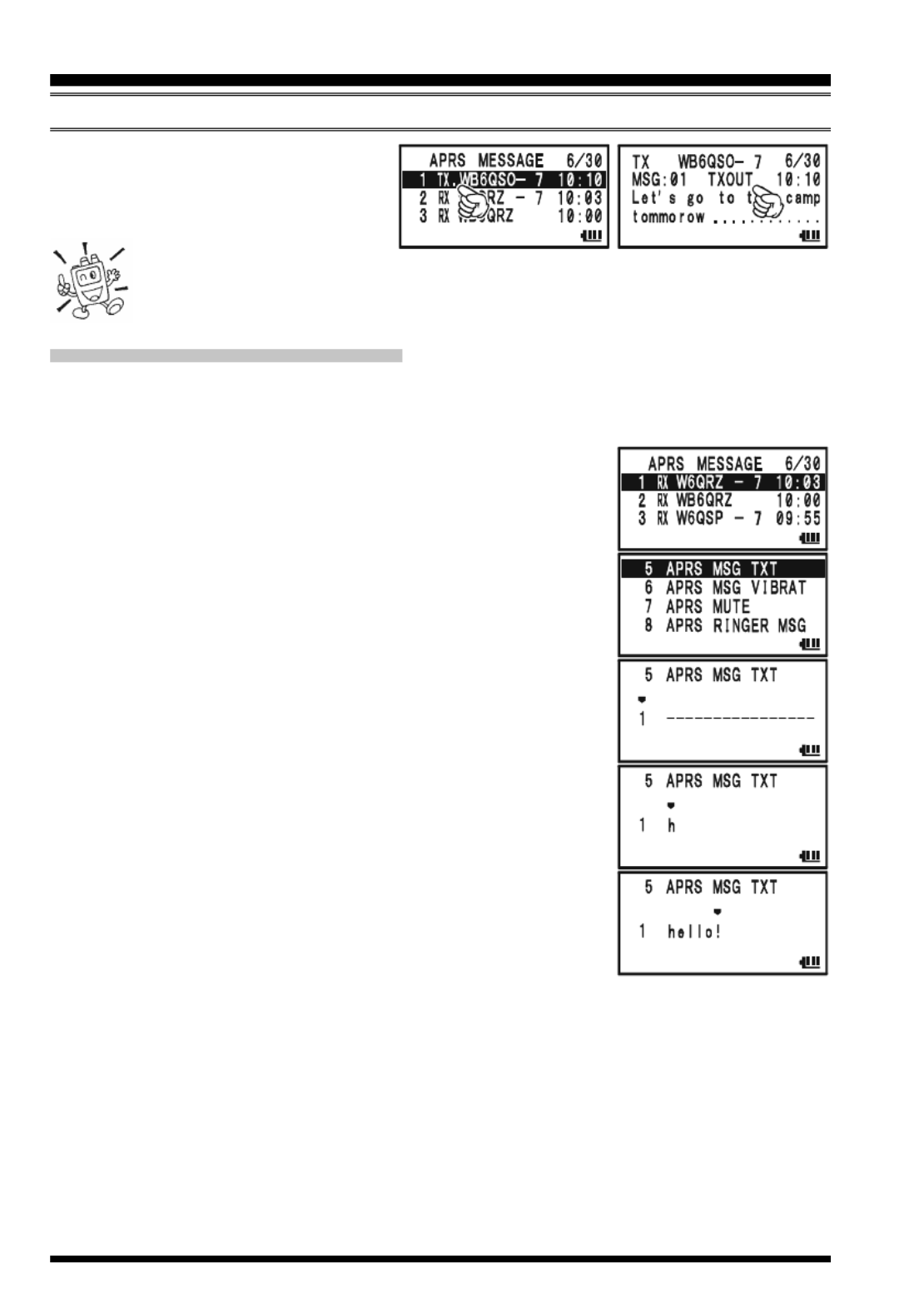
VX-8GR/GE OPERATING MANUAL82
APRS® OPERATION
T RANSMIT AN APRS MESSAGE
pear on the display, instead of the
remaining number of transmis-
sions.
You may select the num-
bers and letters for the callsign and message with the key buttons (1 through
9 0, and ) in the same way as labeling memories.
S TORE THE F FIXED ORM MESSAGE
The VX-8GR/GE allows you to store seven fixed form messages (up to 16 characters for
each message).
1. Press the m key several times until the APRS MESSAGE
screen appears on the display.
2. Press and hold the m key for one second to enter the
APRS/GPS Set Mode.
3. Rotate the DIAL knob to select Set Mode Item 5: APRS
MSG TXT.
4. Press the m key briefly to enable adjustment of this Set
Mode Item.
5. Rotate the DIAL knob to select the Message register (1 - 7)
you wish to store your message to.
6. Press the M key briefly to begin message entry into the
selected resister.
7. Rotate the DIAL knob (or press the keyboard) to select the
first character of the message.
8. Press the M key to move to the next character.
9. Repeat steps 7 and 8 to program the remainder of the mes-
sage.
10. If you make a mistake, press the B key to backspace
the cursor and then enter the correct character.
11. When you have completed your message entry, press the PTT switch to save the new
setting and exit to the APRS MESSAGE screen.

VX-8GR/GE OPERATING MANUAL 85
ARTSTM ALERT BEEP OPTIONS
The ARTSTM feature allows two kinds of alert beeps (with the additional option of turning
them off), to alert you to the current status of ARTS
TM operation. Depending on your
location and the potential annoyance associated with frequent beeps, you may choose the
Beep mode which best suits your needs. The choices are:
IN RANGE: The beeps are issued only when the radio first confirms that you are
within range, but does not re-confirm with beeps thereafter.
ALWAYS: Every time a polling transmission is received from the other station, the
alert beeps will be heard.
OFF: No alert beeps will be heard; you must look at the display to confirm
current ARTSTM status.
To set the ARTSTM Beep mode, use the following procedure:
1. Press and hold the m key for one second to enter the Set Mode.
2. Rotate the DIAL knob to select Set Mode Item 3: ARTS
BEEP.
3. Press the m key briefly to enable adjustment of this Set
Mode Item.
4. Rotate the DIAL knob to select the desired ARTS Beep mode
(see above).
5. Press the PTT switch briefly to save the new setting and
exit to normal operation.
ARTSTM (AUTOMATIC RANGE T SRANSPONDER YSTEM
)

VX-8GR/GE OPERATING MANUAL86
CW IDENTIFIER SETUP
The ARTSTM feature includes a CW identifier, as discussed previously. Every ten minutes
during ARTSTM operation, the radio can be instructed to send “DE (your callsign) K” if
this feature is enabled. The callsign field may contain up to 16 characters.
Here is how to program the CW Identifier:
1. Press and hold the m key for one second to enter the Set Mode.
2. Rotate the DIAL knob to select Set Mode Item 16: CW ID.
3. Press the m key briefly to enable adjustment of this Set
Mode Item.
4. Rotate the DIAL knob to select “ON” (to activate the CW
ID function).
5. Press the M key to enable programming your callsign.
Press and hold the h key for two seconds to clear any
previous callsign, if desired.
6. Rotate the DIAL knob or press the keyboard to set the first
letter or number in your callsign.
Example 1: Rotate the DIAL knob to select any of the 37
available characters.
Example 2: Press the 9 key repeatedly to toggle among
the five available characters associated with
that key: W X Y Z 9 W.....
7. Press the M key to move on to the next character, if
needed.
8. Repeat steps 6 and 7 as many times as necessary to com-
plete your callsign. Note that the “slant bar” (– • • – •) is
among the available characters, should you be a “portable”
station.
9. Press and hold the h key for two seconds to delete all data after the cursor that may
have been previously stored.
10. If you make a mistake, press the B key to backspace the cursor, and then enter the
correct letter/number.
11. When you have entered your entire callsign, press the m
key briefly to confirm the callsign, then press the PTT switch
to save the settings and exit to normal operation.
1) You may check your work by monitoring the entered callsign. To do this,
repeat steps 1 - 3 above, then press the f key.
2) You may adjust the monitoring tone (CW sidetone pitch) via Set Mode
Item 18: CW PITCH. Available selections are 400 - 1000 Hz (50 Hz/step).
ARTSTM (AUTOMATIC RANGE TRANSPONDER SYSTEM
)

VX-8GR/GE OPERATING MANUAL 87
The Spectrum Analyzer allows viewing operating activity on channels above or below the
current operating channel in the VFO mode.
The display indicates the relative signal strength on channels immediately adjacent to the
current operating frequency.
The Spectrum Analyzer feature can be activated only while the VX-8GR/GE is in the
“Mono” band mode.
Three basic operating modes for the Spectrum Analyzer are available:
1Time: In this mode, the transceiver sweeps the current band once.
CONTINUOUS: In this mode, the transceiver sweeps the current band repeatedly until the
c key is pressed, or the Spectrum Analyzer is turned off.
Full Time: This mode is activated similar to a “CONTINUOUS” mode. However, the
transceiver outputs the audio of the center frequency (
) from a speaker
when the Spectrum Analyzer is activated between 108 ~ 580 MHz.
S ETTING UP THE SPECTRUM ANALYZER :MODE
1. Press and hold the m key for one second to enter the Set Mode.
2. Rotate the DIAL knob to select Set Mode Item 84: SPEC-
ANALYZER.
3. Press the m key briefly to enable adjustment of this Set
Mode Item.
4. Rotate the DIAL knob to select the desired Spectrum Ana-
lyzer mode (see above).
5. Press the PTT switch momentarily to save the new setting
and exit to normal operation.
T O ACTIVATE THE SPECTRUM ANALYZER:
1. Set the radio to the VFO mode in the “Mono” band mode.
2. Press the key, then press the f 8 key to activate the
Spectrum Analyzer.
3. When the Spectrum Analyzer is activated, press the a or
b key to change the visible bandwidth. Available selec-
tions are ±5, ±9, ±16, ±24, and ±50 channels (default: ±16 channels). The visible
bandwidth, however, depends on the selected channel step size, so match the default
channel steps with the amateur band you are using.
4. To turn the Spectrum Analyzer off and operate on the center (displayed) channel,
press the c key to stop the sweep, if needed, then press the f key followed by
8 key.
SPECTRUM ANALYZER OPERATION

VX-8GR/GE OPERATING MANUAL88
The Smart Search feature allows you to load frequencies automatically according to where
activity is encountered by your radio. When Smart Search is engaged, the transceiver will
search above and below your current frequency, storing active frequencies as it goes (with-
out stopping on them even briefly); these frequencies are stored into a special Smart Search
memory band, consisting of 31 memories (15 above the current frequency, 15 below the
current frequency, plus the current frequency itself).
Two basic operating modes for Smart Search are available:
SINGLE: In this mode, the transceiver will sweep the current band once in each
direction starting on the current frequency. All channels where activity is
present will be loaded into the Smart Search memories; whether or not
all 31 memories are filled, the search will stop after one sweep in each
direction.
CONTINUOUS: In this mode, the transceiver will make one pass in each direction as with
One-Shot searching; if all 31 channels are not filled after the first sweep,
however, the radio will continue sweeping until they are all filled.
The Smart Search feature can only be activated while the VX-8GR/GE is oper-
ating in the Mono band mode.
S ETTING THE S SMART EARCH MODE
1. Press and hold the m key for one second to enter the Set Mode.
2. Rotate the DIAL knob to select Set Mode Item 82: SMART
SEARCH.
3. Press the m key briefly to enable adjustment of this Set
Mode Item.
4. Rotate the DIAL knob to select the desired Smart Search
mode (see above).
5. Press the PTT switch briefly to save the new setting and
exit to normal operation.
STORING SMART SEARCH MEMORIES
1. Set the radio to the VFO mode in the “Mono” band mode. Be sure that you have the
Squelch adjusted properly (so that band noise is quieted).
2. Press and hold the M key until the “SMART SEARCH”
notation appears.
3. Press and hold the B key for one second to begin the
Channel Counter.
4. As active channels are detected, you will observe the number of “loaded” channels
increasing in the regular memory channel window.
5. Depending on the mode you set for Smart Search operation (“SINGLE” or “CON-
TINUOUS”), the Smart Search scan will eventually terminate, and the LCD will re-
SMART SEARCH OPERATION

VX-8GR/GE OPERATING MANUAL 89
vert to Smart Search Memory Channel “CNT.”
6. To recall the Smart Search memories, rotate the DIAL to
choose from among the Smart Search memories.
7. To return to normal operation, press the key.
Smart Search is a great tool when visiting a city for the first time. You don’t
need to spend hours looking up repeater frequencies from a reference
guidebook…just ask your VX-8GR/GE where the action is!
SMART SEARCH OPERATION

VX-8GR/GE OPERATING MANUAL90
GENERAL
The VX-8GR/GE provides a message feature, which sends a message (up to 16 charac-
ters) instead of sending a voice. 20 different messages can be programmed, any one of
them can be selected and transmitted with your ID.
Note
The Message Feature requires that all members (1) use the Yaesu VX-8GR/
GE, VX-8DR/DE, VX-8R/E VX-3R/E, , or FTM-10R/E/SR/SE transceiver,
(2) store the same messages into the message slots, (3) store the same mem-
ber list into the member box, and (4) set the same frequency.
Does not send the Message through a repeater.
P ROGRAMMING A MESSAGE
(Requires all members set the same messages into the same message slots in the same
order.)
The VX-8GR/GE has 20 message slots, including a factory-programmed message (EMER-
GENCY). The factory-programmed message of course can be overwritten at any time
with personalized messages.
1. Press and hold the m key for one second to enter the Set Mode.
2. Rotate the DIAL knob to select Set Mode Item 54: MES-
SAGE SELECT.
3. Press the m key briefly to enable adjustment of this Set
Mode Item.
4. Rotate the DIAL knob to select the desired Message slot
into which you wish to store a message. The LCD displays
the previously stored message.
5. Press the M key briefly to enable programming of the
message.
6. Press and hold in the h key for one second to clear the
previously stored message, if desired.
7. Rotate the DIAL knob or press the keyboard to set the first
character of the message you wish to store.
Example 1: Rotate the DIAL knob to select any of the 61
available characters.
Example 2: Press the 2 key repeatedly to toggle among
the seven available characters associated with that
key: a b c A B C 2 a
.....
8. Press the M key to move on to the next character, if
needed.
MESSAGE FEATURE

VX-8GR/GE OPERATING MANUAL 91
9. Repeat steps 7 and 8 above to complete the message (up to
16 characters). If you make a mistake, press the B key
to move back to the incorrect character, and then enter the
correct character.
10. Press and hold in the h key for one second to delete all data after the cursor that
may have been previously stored.
11. When the Message entry is complete, press the m key
briefly to save the new setting.
12. If you wish to store another message, repeat steps 3 through
11 above.
13. Press the PTT switch to exit to normal operation.
P ROGRAMMING A MEMBER LIST
(Requires all members to enter the same member list (includes own ID) into the same
member box in the same order.)
It is possible to register a maximum of 20 persons, in order to identify the sender. When
you receive a message transfer, you will know who sent the message by the ID in the
register. In addition, your ID can be sent to the other members when you transmit any
messages to them.
If all the members share the register information (ID), the message sender ID will be
shown on the display when receiving the message.
Even if no IDs are registered, the message function can still work. However, in this case,
“MESSAGE1” though “MESSAGE20” will be displayed when receiving a message.
We recommend that you use your call sign for the member list.
1. Press and hold the m key for one second to enter the Set Mode.
2. Rotate the DIAL knob to select Set Mode Item 52: MES-
SAGE LIST.
3. Press the m key briefly to enable adjustment of this Set
Mode Item.
4. Rotate the DIAL knob to select the desired member box (1
~ 20) into which you wish to store a member ID. The LCD
will display the previously stored personal ID.
5. Press the M key briefly to enable programming of the
personal ID.
6. Press and hold in the h key for two seconds to clear the
previously stored personal ID, if desired.
7. Rotate the DIAL knob or press the keyboard to set the first
MESSAGE FEATURE
P ROGRAMMING A MESSAGE
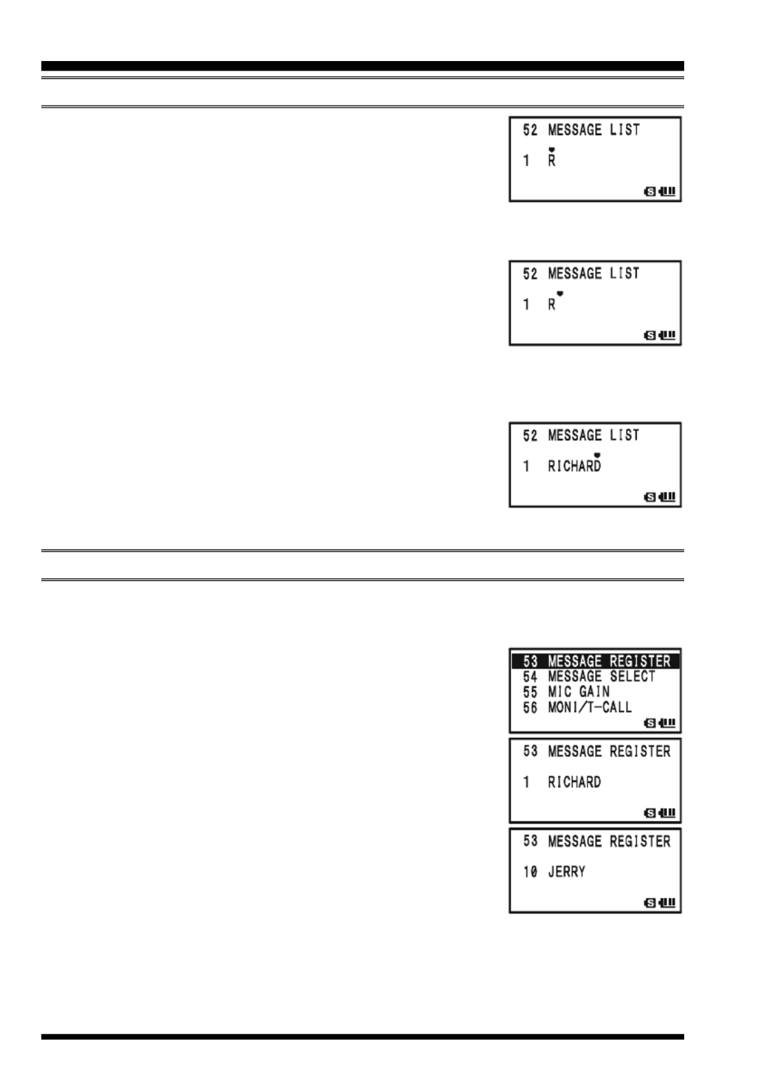
VX-8GR/GE OPERATING MANUAL92
character of the message you wish to store.
Example 1: Rotate the DIAL knob to select any of the 61
available characters.
Example 2: Press the 7 key repeatedly to toggle among
the nine available characters associated with that key: p q r s
P Q R S 7 p.....
8. Press the M key to move on to the next character, if
needed.
9. Repeat steps 7 and 8 above to complete the personal ID (up
to 8 characters). If you make a mistake, press the B key
to move back to the incorrect character, and then enter the correct character.
10. Press and hold in the h key for two seconds to delete all data after the cursor that
may have been previously stored.
11. When the personal ID entry is complete, press the m key
briefly to save the new setting.
12. If you wish to store another personal ID, repeat steps 3
through 10 above.
13. Press the PTT switch to exit to normal operation.
S PET YOUR ERSONAL ID
You may choose your personal ID from the member list as follows.
1. Press and hold the m key for one second to enter the Set Mode.
2. Rotate the DIAL knob to select Set Mode Item 53: MES-
SAGE REGISTER.
3. Press the m key briefly to enable adjustment of this Set
Mode Item.
4. Rotate the DIAL knob to select the member box (1 ~ 20)
where your ID is stored.
5. Press the PTT switch briefly to save the new setting and
exit to normal operation.
MESSAGE FEATURE
P ROGRAMMING A MEMBER LIST

VX-8GR/GE OPERATING MANUAL 93
S ENDING A MESSAGE
The registered message can be sent to the members who are receiving on the coordination
frequency. When a message is sent, the transmitter’s ID will be sent also, and the receiver
can identify who sent the message.
The “Personal ID” setting (described in the previous paragraph) is required for
the transmitter’s ID to be shown with the received message.
1. Set the radio to the coordination frequency.
2. Press and hold the m key for one second to enter the Set Mode.
3. Rotate the DIAL knob to select Set Mode Item 54: MES-
SAGE SELECT.
4. Press the m key briefly to enable adjustment of this Set
Mode Item.
5. Rotate the DIAL knob to select the desired Message slot
you wish to send.
6. Press the PTT switch to exit to normal operation.
7. Press the f key, then press the M key. This provides a
“Short-cut” to Menu Item 88: SQL TYPE.
8. Rotate the DIAL knob until “MESSAGE” appears on the
display; this activates the Message feature.
9. Press the PTT switch to exit from the Menu mode and acti-
vate the Message feature. When the Message feature is ac-
tivated, the “MSG” notation will appear on the display.
10. Press the PTT switch again (without speaking into the mi-
crophone) to transmit the selected message on the coordina-
tion frequency. It takes approximately 6 seconds to transmit the message.
MESSAGE FEATURE

VX-8GR/GE OPERATING MANUAL96
EMERGENCY FEATURE
EMERGENCY AUTOMATIC ID (EAI) FEATURE
The Emergency Automatic ID (EAI) feature can be used to aid in searching for persons
who are incapacitated in disasters like earthquakes, especially search-and-rescue person-
nel who may have become injured in a debris field. When using the EAI feature, a searcher
transmits a unique command (CTCSS tone pair), which will automatically cause the in-
jured party’s radio to transmit, so others may perform direction-finding and effect a res-
cue. The incapacitated party may not be able to speak or even press the PTT switch. The
callsign of the incapacitated person will also be transmitted, to assist the rescue team.
If an emergency group is working in a dangerous area, all members should engage the
EAI feature on their transceiver, so that others can assist a fallen team member, if neces-
sary.
When the Emergency Automatic ID (EAI) Feature is activated, and the VX-8GR/GE
receives the CTCSS tone pair, the radio will transmit a loud (0.5 second) beep every 2.5
seconds until the EAI timer expires.
The EIA is activated when the CTCSS tone pair stored in the Receiving Pager Code Memory
(configured via Set Mode Item 62: PAGE CODE-RX) is received for 5 seconds on the
frequency, which is stored in Memory Channel “EAI”. It is NOT necessary for the inca-
pacitated person to press the PTT switch.
A call sign may be stored in the radio and the CW identifier enabled via Set Mode Item
16: CW ID. Then, when the EAI feature is activated in the Interval mode, the radio will
transmit the callsign once each minute. In addition, the bright LED will blink the call sign
in Morse code. The “callsign” ID can be changed to any desired sequence up to 16 char-
acters, such as a name. The radio will transmit a loud (0.5 second) beep every 2.5 seconds,
and send the call sign each minute, until the EAI timer expires.
The Emergency Automatic ID (EAI) Feature requires that you:
1) Store the CTCSS Tone Pair into the Receiving Pager Memory (see page 25 for the
procedure),
2) Store the desired UHF coordination frequency into Memory Channel “EAI” (see page
43 for procedure). (We suggest using a frequency different from your normal operat-
ing channel.)
3) Set the operating band to “A-Band”.
4) Activate the EAI function “Set Mode Item 27: EAI” to “ON”. The VX-8GR/GE radio
may now be used normally.
The EIA function will monitor the EIA memory channel in the background, and it will be
activated when the Pager Memory Tone Pair is received on the EIA memory channel.
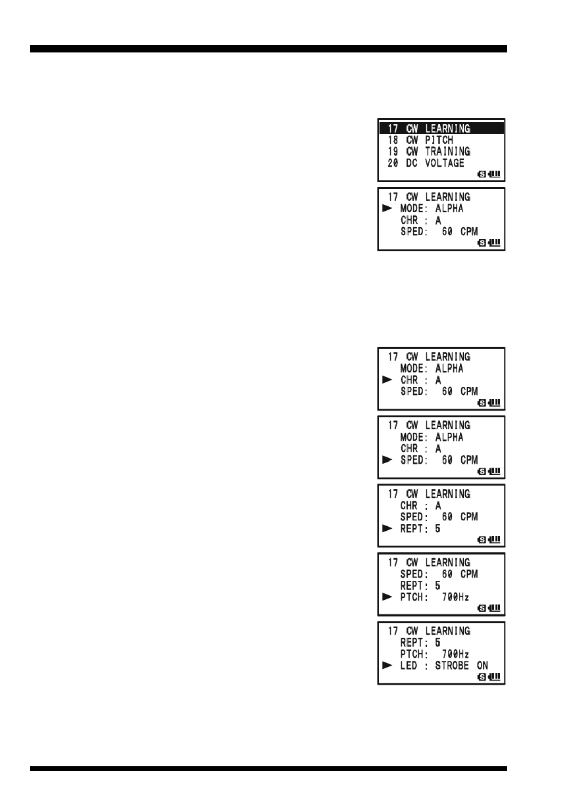
VX-8GR/GE OPERATING MANUAL104
The VX-8GR/GE provides a CW learning feature, which sends the designated Morse
Code via the sidetone (heard in the speaker) to help your CW learning.
1. Press and hold the m key for one second to enter the Set Mode.
2. Rotate the DIAL knob to select Set Mode Item 17: CW
LEARNING.
3. Press the m key briefly to enable adjustment of this Set
Mode Item.
4. Rotate the DIAL knob to select the Training mode (displayed
in fine print at the upper edge of the LCD):
ALPHA: Sends the Alphabet characters
ALPHA AUTO: Sends the Alphabet characters (move to
next character automatically)
NUMBER: Sends the Numeric characters
NUMBER AUTO: Sends the Numeric characters (move to next character automatically)
SYMBL: Sends the Symbol characters
SYMBL AUTO: Sends the Symbol characters (move to next character automatically)
5. Press the b key to change the cursor to “CHR”, then ro-
tate the DIAL knob to select the CW code which you want
to learn.
6. Press the b key to change the cursor to “SPED”, then
rotate the DIAL knob to select the Morse speed. You may
select the units of the code speed in either “CPM (charac-
ters per minute)” or “WPM (Words per minute)” using the
DIAL knob from Set Item “FORM”.
7. Press the b key to change the cursor to “REPT”, then
rotate the DIAL knob to select the sending repetition (1 -
9).
8. Press the b key to change the cursor to “PTCH”, then
rotate the DIAL knob to adjust the CW sidetone pitch (400
- 1000 Hz, 50 Hz/step).
9. Press the b key to change the cursor to “LED”, then ro-
tate the DIAL knob to switch the flashing of the (white)
LED light “on” and “off”.
10. Press the f key to begin generating the selected code
characters the designated number of times (Only the speaker
CW sidetone is heard, the radio does not transmit).
11. You may adjust the CW sidetone audio level by rotating the DIAL knob while press-
ing and holding the g key.
12. If one of the “AUTO” modes is not selected in step 4 above, press the f key to send
again, or select another code by rotating the DIAL knob from “CHR” item and press
CW LEARNING FEATURE

VX-8GR/GE OPERATING MANUAL106
The VX-8GR/GE provides another CW learning feature; call it a CW Training feature,
which sends random Morse Code via the sidetone (heard in the speaker), so you can
improve your CW proficiency.
1. Press and hold the m key for one second to enter the Set Mode.
2. Rotate the DIAL knob to select Set Mode Item 19:
CW TRAINING.
3. Press the m key briefly to enable adjustment of
this Set Mode Item.
4. Rotate the DIAL knob to select the Training mode (displayed
in fine print at the upper edge of the LCD):
ALPHA 5CHR: Sends five Alphabet characters only
ALPHA REPT: Sends Alphabet characters only (Repeatedly)
NUMBER 5CHR: Sends five Numeric characters only
NUMBER REPT: Sends Numeric characters only (Repeatedly)
MIX 5CHR: Sends five Alphabet, Numeric, “?”, and “/” characters (Mixed)
MIX REPT: Sends Alphabet, Numeric, “?”, and “/” characters (Mixed, Con-
tinuously in groups of five)
5. Press the b key to change the cursor to “SPED”, then
rotate the DIAL knob to select the Morse speed. You may
select the units of the code speed between “CPM (charac-
ters per minute)” and “WPM (Words per minute)” by the
DIAL knob from Set Item “FORM”.
6. Press the b key to change the cursor to “PTCH”, then
rotate the DIAL knob to adjust the CW sidetone pitch (400
- 1000 Hz, 50 Hz/step).
7. Press the b key to change the cursor to “LED”, then ro-
tate the DIAL knob to switch the flashing of the (white)
LED light “on” and “off”.
8. Press the a b/ key to change the cursor to “MODE.
9. Press the f key to begin generation of the code characters
(CW sidetone only, the radio does not transmit); the gener-
ated characters will appear at the right of the “CHR” item.
10. You may adjust the CW sidetone audio level by rotating the
DIAL knob while pressing and holding the g key.
11. If one of the “5CHR” modes is selected in step 4 above, press the f key to send
another code group.
12. To stop CW generation, press the f key again.
13. To disable CW training feature, press the PTT switch.
The “CPM” selection is based on the international “PARIS” standard, which
stipulates five characters per word.
CW TRAINING FEATURE

VX-8GR/GE OPERATING MANUAL 107
SENSOR MODE
The VX-8GR/GE always displays the “Battery Voltage” and
“Current Time” while the VX-8GR/GE is operating in the
“Mono” band mode with the Large characters. You may change
the “Battery Voltage” display to the “Temperature” display which
indicates the current temperature inside the transceiver’s case.
To change the display from the “Battery Voltage” to the “Temperature”:
1. Press and hold the m key for one second to enter the Set Mode.
2. Rotate the DIAL knob to select Set Mode Item 78:
SENSOR DISPLAY.
3. Press the m key briefly to enable adjustment of
this Set Mode Item.
4. Rotate the DIAL knob to select “TEMP”.
5. Press the PTT switch briefly to exit to normal op-
eration and display the sensor information on the dis-
play.
To return to the “Battery Voltage” display, just repeat the above procedure, rotating the
DIAL knob to select “DC” in step “4” above.
1) When “OFF” is selected in step “4” above, the VX-8GR displays only the
“Current Time” while the VX-8GR/GE is operating in the “Mono” band
mode with the Large characters.
2) You may monitor the “Battery Voltage” using Set Mode Item 20: DC VOLTAGE, and
the “Temperature” using Set Mode Item 79: SENSOR INFO .
CLOCK SET
The VX-8GR/GE has a 24-hour clock with a calendar which covers all dates from Janu-
ary 1, 2000 through December 31, 2099 (accuracy: ±30 sec/month).
NOTE: Before setting the CLOCK SET, set the TIME ZONE (TIME OFFSET) for
your area. Refer to page 67.
To set the clock:
1. Press and hold the m key for one second to enter the Set Mode.
2. Rotate the DIAL knob to select Set Mode Item 90: TIME
SET.
3. Press the m key briefly to enable adjustment of this Menu
Item.
4. Rotate the DIAL knob to select the “year” setting.
5. Press the M key briefly, then rotate the DIAL knob to
select the “month” setting.
6. Repeat the above step to set the “day,” “day of the week,”
“hour,” and “minute” selections.
Specyfikacje produktu
| Marka: | Yaesu |
| Kategoria: | radio |
| Model: | VX-8GR |
Potrzebujesz pomocy?
Jeśli potrzebujesz pomocy z Yaesu VX-8GR, zadaj pytanie poniżej, a inni użytkownicy Ci odpowiedzą
Instrukcje radio Yaesu

12 Września 2024
11 Września 2024
5 Września 2024
31 Sierpnia 2024
31 Sierpnia 2024
29 Sierpnia 2024
28 Sierpnia 2024
28 Sierpnia 2024
27 Sierpnia 2024
25 Sierpnia 2024
Instrukcje radio
- radio Sony
- radio Yamaha
- radio AEG
- radio Sven
- radio Motorola
- radio Stabo
- radio Logitech
- radio Sharp
- radio Pioneer
- radio Milwaukee
- radio Philips
- radio SilverCrest
- radio Technics
- radio Bosch
- radio JBL
- radio Onkyo
- radio Easy Home
- radio Scott
- radio Festool
- radio Kärcher
- radio Bose
- radio Panasonic
- radio Muse
- radio SW-Stahl
- radio Nedis
- radio Stanley
- radio Be Cool
- radio Medion
- radio Tangent
- radio Boss
- radio Black & Decker
- radio OK
- radio Lenco
- radio Adler
- radio Marquant
- radio Toshiba
- radio Majestic
- radio Quigg
- radio Jensen
- radio August
- radio ILive
- radio Garmin
- radio Blaupunkt
- radio Terris
- radio Salora
- radio Teac
- radio DeWalt
- radio Dual
- radio Einhell
- radio Grundig
- radio Soundmaster
- radio Hyundai
- radio DAP-Audio
- radio Manhattan
- radio ECG
- radio Matsui
- radio Makita
- radio Denon
- radio Block
- radio Ozito
- radio Audac
- radio Cambridge
- radio Kenwood
- radio Icy Box
- radio Polk
- radio RYOBI
- radio Alpine
- radio Zebra
- radio Cobra
- radio JVC
- radio BLUEPALM
- radio Memphis Audio
- radio Furrion
- radio Moulinex
- radio DEDRA
- radio Oricom
- radio Hilti
- radio Dartel
- radio Lowrance
- radio TechniSat
- radio Auna
- radio Vimar
- radio Schneider
- radio Krüger&Matz
- radio OneConcept
- radio Emos
- radio Renkforce
- radio Pure
- radio BaseTech
- radio Uniden
- radio Clarion
- radio Thomson
- radio La Crosse Technology
- radio Velleman
- radio Ferguson
- radio Fusion
- radio Intertechno
- radio DreamGEAR
- radio Manta
- radio Pyle
- radio NGS
- radio CRUX
- radio Midland
- radio Sennheiser
- radio Camry
- radio Lenoxx
- radio Imperial
- radio Monitor Audio
- radio Audio Pro
- radio Nevir
- radio TriStar
- radio Bogen
- radio ION
- radio Delta
- radio Harman Kardon
- radio Audio-Technica
- radio Maginon
- radio SPC
- radio GoGen
- radio Sonoro
- radio Parrot
- radio Aiwa
- radio JL Audio
- radio AKAI
- radio Sanyo
- radio ICOM
- radio Acoustic Energy
- radio Majority
- radio Teufel
- radio Clatronic
- radio Tronic
- radio Telefunken
- radio Oregon Scientific
- radio Viper
- radio Kicker
- radio Aluratek
- radio Omnitronic
- radio Olympia
- radio Hama
- radio Duronic
- radio Sagemcom
- radio Bush
- radio Schwaiger
- radio Sangean
- radio Navman
- radio Hager
- radio Victrola
- radio Elta
- radio Mac Audio
- radio Infinity
- radio Denver
- radio Albrecht
- radio Hitachi
- radio Hertz
- radio Emerson
- radio Craftsman
- radio Busch-Jaeger
- radio RCA
- radio Klein Tools
- radio Futaba
- radio Trevi
- radio Technaxx
- radio Xhdata
- radio Sirius
- radio Lexibook
- radio GPX
- radio Topcom
- radio PowerPlus
- radio Sencor
- radio Noxon
- radio Vonroc
- radio Tesco
- radio HiKOKI
- radio EasyMaxx
- radio Power Dynamics
- radio Tecsun
- radio Alecto
- radio Kathrein
- radio Binatone
- radio Rockford Fosgate
- radio JUNG
- radio Timex
- radio Monacor
- radio Daewoo
- radio Audizio
- radio Laser
- radio Kunft
- radio Roberts
- radio H-Tronic
- radio Porter-Cable
- radio Metabo
- radio Weather X
- radio MAAS
- radio Terratec
- radio Axxess
- radio Cotech
- radio Vitek
- radio Geneva
- radio Clas Ohlson
- radio Reflexion
- radio Sogo
- radio REVO
- radio Crosley
- radio Proline
- radio Schaub Lorenz
- radio Artsound
- radio Data-Tronix
- radio AMX
- radio Swan
- radio Argon
- radio Brennenstuhl
- radio Tevion
- radio GPO
- radio Caliber
- radio Exibel
- radio Logik
- radio Telestar
- radio Sagem
- radio Brigmton
- radio Sunstech
- radio GlobalTronics
- radio Nordmende
- radio AudioAffairs
- radio Steren
- radio Audiosonic
- radio Coby
- radio Envivo
- radio Bigben Interactive
- radio Technoline
- radio Audiovox
- radio MB Quart
- radio Switel
- radio Bigben
- radio Sunwind
- radio Alba
- radio Naxa
- radio Lexon
- radio Ricatech
- radio Konig
- radio Boston Acoustics
- radio Mpman
- radio Sweex
- radio Ices
- radio Nikkei
- radio PerfectPro
- radio Peaq
- radio Freecom
- radio Roadstar
- radio Gira
- radio Dnt
- radio Balance
- radio MT Logic
- radio Difrnce
- radio HQ
- radio Noveen
- radio Irradio
- radio Karcher Audio
- radio PAC
- radio IHome
- radio AIC
- radio Ruarkaudio
- radio Tivoli Audio
- radio Go Green
- radio Wolfgang
- radio Linn
- radio Numan
- radio Iluv
- radio TELEX
- radio Aconatic
- radio Multiplex
- radio Clint
- radio Soundstream
- radio Xoro
- radio Zolid
- radio Berker
- radio Woxter
- radio View Quest
- radio Harley Davidson
- radio Hitec
- radio Orava
- radio Brionvega
- radio Wet Sounds
- radio Eissound
- radio Dcybel
- radio JGC
- radio Scansonic
- radio TFA Dostmann
- radio Audisse
- radio Tivoli
- radio ETON
- radio Kruger Matz
- radio Equity
- radio EKO
- radio Pinell
- radio Videologic
- radio Mtx Audio
- radio Aquatic AV
- radio Roswell
- radio Intek
- radio Digitalbox
- radio Whistler
- radio Xact
- radio Ruark Audio
- radio Magnavox
- radio Digitech
- radio GME
- radio NUVO
- radio Narex
- radio Tiny Audio
- radio R-MUSIC
- radio E-bench
- radio Konig Electronic
- radio Peha
- radio SiriusXM
- radio Sanwa
- radio Sailor
- radio SSV Works
- radio Microlab
- radio QFX
- radio Voxx
- radio SACK It
- radio BasicXL
- radio Roth
- radio Ices Electronics
- radio AmpliVox
- radio Elbe
- radio GBS Elettronica
- radio Sang
- radio Gewiss
- radio Lutron
- radio Retekess
- radio Wintal
- radio Acoustic Solutions
- radio Atlantis Land
- radio Ranger
- radio Mebby
- radio Blonder Tongue
- radio Yamazen
- radio MOOOV
- radio RoadKing
Najnowsze instrukcje dla radio
2 Kwietnia 2025
2 Kwietnia 2025
1 Kwietnia 2025

1 Kwietnia 2025
1 Kwietnia 2025
29 Marca 2025
26 Marca 2025

24 Marca 2025
14 Marca 2025
11 Marca 2025