Instrukcja obsługi Panasonic PT-RW330E
Panasonic
projektor wideo
PT-RW330E
Przeczytaj poniżej 📖 instrukcję obsługi w języku polskim dla Panasonic PT-RW330E (127 stron) w kategorii projektor wideo. Ta instrukcja była pomocna dla 19 osób i została oceniona przez 2 użytkowników na średnio 4.5 gwiazdek
Strona 1/127

Thank you for purchasing this Panasonic product.
■The Operating Instructions correspond to the rmware’s main version 3.02 and higher.
■Before operating this product, please read the instructions carefully and save this manual
for future use.
■Before using your projector, be sure to read “Read this rst!” ( x pages 2 to 7).
Model No. PT-RZ370E
PT-RW330E
TQBJ0491-3
DLPTM Projector Commercial Use
Operating Instructions
Functional Manual
ENGLISH

2 - ENGLISH
Read this rst!
Read this rst!
WARNING: THIS APPARATUS MUST BE EARTHED.
WARNING: To prevent damage which may result in re or shock hazard, do not expose this appliance to rain
or moisture.
This device is not intended for use in the direct eld of view at visual display workplaces. To avoid
incommoding reexions at visual display workplaces this device must not be placed in the direct
eld of view.
The equipment is not intended for used at a video workstation in compliance BildscharbV.
The sound pressure level at the operator position is equal or less than 70 dB (A) according to ISO 7779.
WARNING:
1. Remove the plug from the mains socket when this unit is not in use for a prolonged period of time.
2. To prevent electric shock, do not remove cover. No user serviceable parts inside. Refer servicing to qualied
service personnel.
3. Do not remove the earthing pin on the mains plug. This apparatus is equipped with a three prong
earthingtype mains plug. This plug will only t an earthing-type mains socket. This is a safety feature. If you
are unable to insert the plug into the mains socket, contact an electrician. Do not defeat the purpose of the
earthing plug.
WARNING:
This is a class A product. In a domestic environment this product may cause radio interference in which case
the user may be required to take adequate measures.
CAUTION: To assure continued compliance, follow the attached installation instructions, which include
using the provided power cord and shielded interface cables when connecting to computer or
peripheral device. If you use serial port to connect PC for external control of projector, you must
use a commercial RS-232C serial interface cable with ferrite core. Any unauthorized changes or
modications to this equipment will void the user’s authority to operate.
This is a device to project images onto a screen, etc., and is not intended for use as indoor lighting in a
domestic environment.
Directive 2009/125/EC
Notice on laser
This projector is the Class 1 laser product that complies with IEC 60825-1.
Product information (for Turkey only)
EEE Yönetmeliğine Uygundur.
EEE Complies with Directive of Turkey.
Importer’s name and address within the European Union
Panasonic Marketing Europe GmbH
Panasonic Testing Center
Winsbergring 15, 22525 Hamburg, Germany

ENGLISH - 3
Read this rst!
WARNING:
POWER
The wall outlet or the circuit breaker shall be installed near the equipment and shall be easily accessible
when problems occur. If the following problems occur, cut off the power supply immediately.
Continued use of the projector in these conditions will result in re or electric shock.
zIf foreign objects or water get inside the projector, cut off the power supply.
zIf the projector is dropped or the cabinet is broken, cut off the power supply.
zIf you notice smoke, strange smells or noise coming from the projector, cut off the power supply.
Please contact an Authorized Service Center for repairs, and do not attempt to repair the projector yourself.
During a thunderstorm, do not touch the projector or the cable.
Electric shocks can result.
Do not do anything that might damage the power cord or the power plug.
If the power cord is used while damaged, electric shocks, short-circuits or re will result.
zDo not damage the power cord, make any modications to it, place it near any hot objects, bend it
excessively, twist it, pull it, place heavy objects on top of it or wrap it into a bundle.
Ask an Authorized Service Center to carry out any repairs to the power cord that might be necessary.
Completely insert the power plug into the wall outlet and the power connector into the projector terminal.
If the plug is not inserted correctly, electric shocks or overheating will result.
zDo not use plugs which are damaged or wall outlets which are coming loose from the wall.
Do not use anything other than the provided power cord.
Failure to observe this will result in re or electric shocks. Please note that if you do not use the provided power
cord to ground the device on the side of the outlet, this may result in electric shocks.
Clean the power plug regularly to prevent it from becoming covered in dust.
Failure to observe this will cause a re.
zIf dust builds up on the power plug, the resulting humidity can damage the insulation.
zIf not using the projector for an extended period of time, pull the power plug out from the wall outlet.
Pull the power plug out from the wall outlet and wipe it with a dry cloth regularly.
Do not handle the power plug and power connector with wet hands.
Failure to observe this will result in electric shocks.
Do not overload the wall outlet.
If the power supply is overloaded (ex., by using too many adapters), overheating may occur and re will result.
ON USE/INSTALLATION
Do not place the projector on soft materials such as carpets or sponge mats.
Doing so will cause the projector to overheat, which can cause burns, re or damage to the projector.
Do not set up the projector in humid or dusty places or in places where the projector may come into
contact with oily smoke or steam, ex. a bathroom.
Using the projector under such conditions will result in re, electric shocks or deterioration of components.
Deterioration of components (such as ceiling mount brackets) may cause the projector which is mounted on the
ceiling to fall down.
Do not install this projector in a place which is not strong enough to take the full weight of the projector
or on top of a surface which is sloped or unstable.
Failure to observe this will cause projector to fall down or tip over the projector, and severe injury or damage
could result.

4 - ENGLISH
Read this rst!
WARNING:
Do not cover the air intake/exhaust ports or place anything within 500 mm (20") of them.
Doing so will cause the projector to overheat, which can cause re or damage to the projector.
zDo not place the projector in narrow, badly ventilated places.
zDo not place the projector on cloth or papers, as these materials could be drawn into the air intake port.
Do not look at the light emitted from the lens while the projector is being used.
Doing so can cause loss of sight.
zStrong light is emitted from the projector’s lens. Do not directly look at this light.
Do not expose your eyes and skin to the projection light while the projector is being used.
Possibly hazardous optical radiation is emitted from this product, causing damage to your eyes and skin.
zBe especially careful not to let young children look into the lens. In addition, turn off the power and
disconnect the power plug when you are away from the projector.
Never attempt to remodel or disassemble the projector.
High voltages can cause re or electric shocks.
zFor any inspection, adjustment and repair work, please contact an Authorized Service Center.
Doing so may cause exposure to dangerous laser radiation.
zThe laser module is built in this projector. Follow procedures specied in the Operating Instructions to make
operations and adjustments.
Do not allow metal objects, ammable objects, or liquids to enter inside of the projector. Do not allow
the projector to get wet.
Doing so may cause short circuits or overheating, and result in re, electric shock, or malfunction of the
projector.
zDo not place containers of liquid or metal objects near the projector.
zIf liquid enters inside of the projector, consult your dealer.
zParticular attention must be paid to children.
Use the ceiling mount bracket specied by Panasonic.
Using the ceiling mount bracket other than the specied one will result in falling accidents.
zAttach the supplied safety cable to the ceiling mount bracket to prevent the projector from falling down.
Installation work (such as ceiling mount bracket) should only be carried out by a qualied technician.
If installation is not carried out and secured correctly, it can cause injury or accidents, such as electric shocks.
zBe sure to use the wire provided with the ceiling mount bracket as an extra safety measure to prevent the
projector from falling down. (Install in a different location to the ceiling mount bracket.)

ENGLISH - 5
Read this rst!
WARNING:
ACCESSORIES
Do not use or handle the batteries improperly, and refer to the following.
Failure to observe this will cause burns, batteries to leak, overheat, explode or catch re.
zUse AA/R6/LR6 batteries.
zDo not use unspecied batteries.
zDo not use chargeable batteries.
zDo not disassemble dry cell batteries.
zDo not heat the batteries or place them into water or re.
zDo not allow the + and – terminals of the batteries to come into contact with metallic objects such as
necklaces or hairpins.
zDo not store or carry batteries together with metallic objects.
zStore the batteries in a plastic bag and keep them away from metallic objects.
zMake sure the polarities (+ and –) are correct when inserting the batteries.
zDo not use a new battery together with an old battery or mix different types of batteries.
zDo not use batteries with the outer cover peeling away or removed.
If the battery uid leaks, do not touch it with bare hands, and take the following measures if necessary.
zBattery uid on your skin or clothing could result in skin inammation or injury.
Rinse with clean water and seek medical advice immediately.
zBattery uid coming in contact with your eyes could result in loss of sight.
In this case, do not rub your eyes. Rinse with clean water and seek medical advice immediately.
Do not use the supplied power cord with devices other than this projector.
zUsing the supplied power cord with devices other than this projector may cause short circuits or
overheating, and result in electric shock or re.
Remove the depleted batteries from the remote control promptly.
zLeaving them in the unit may result in uid leakage, overheating, or explosion of the batteries.

6 - ENGLISH
Read this rst!
CAUTION:
POWER
When disconnecting the power cord, be sure to hold the power plug and power connector.
If the power cord itself is pulled, the lead will become damaged, and re, short-circuits or serious electric shocks
will result.
When not using the projector for an extended period of time, disconnect the power plug from the wall
outlet.
Failure to do so may result in re or electric shock.
Disconnect the power plug from the wall outlet before carrying out any cleaning.
Failure to do so may result in electric shock.
ON USE/INSTALLATION
Do not place heavy objects on top of the projector.
Failure to observe this will cause the projector to become unbalanced and fall, which could result in damage or
injury. The projector will be damaged or deformed.
Do not put your weight on this projector.
You could fall or the projector could break, and injury will result.
zBe especially careful not to let young children stand or sit on the projector.
Do not place the projector in extremely hot locations.
Doing so will cause the outer casing or internal components to deteriorate, or result in re.
zTake particular care in locations exposed to direct sunlight or near stoves.
Do not place your hands or other objects close to the air exhaust port.
Doing so will cause burns or damage your hands or other objects.
zHeated air comes out of the air exhaust port. Do not place your hands or face, or objects which cannot
withstand heat close to this port.
Always disconnect all cables before moving the projector.
Moving the projector with cables still attached can damage the cables, which will cause re or electric shocks to
occur.
When mounting the projector on the ceiling, keep mounting screws and power cord from contact with
metal parts inside the ceiling.
Contact with metal parts inside the ceiling can cause electric shocks.
ACCESSORIES
Ask your dealer about cleaning inside the projector every 20 000 hours of usage as an estimated
duration.
Continuous use while dust is accumulated inside the projector may result in re.
zFor cleaning fee, ask your dealer.
When not using the projector for an extended period of time, remove the batteries from the remote
control.
Failure to observe this will cause the batteries to leak, overheat, catch re or explode, which may result in re
or contamination of surrounding area.

ENGLISH - 7
Read this rst!
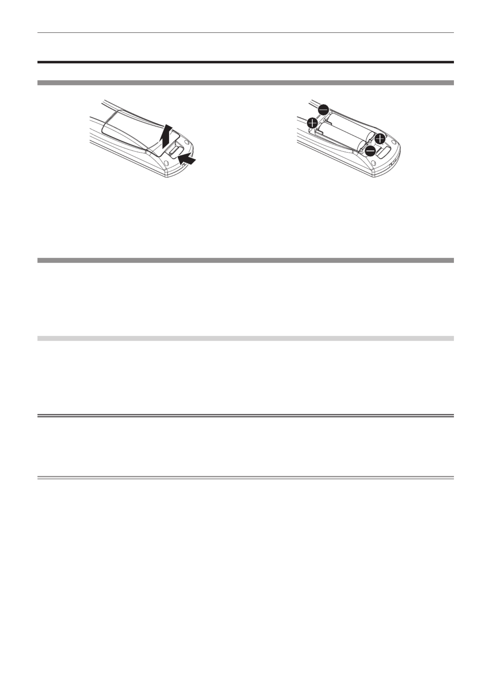
To remove the battery
Remote Control Battery
1. Press the guide and lift the cover.
(i)
(ii)
2. Remove the batteries.

8 - ENGLISH
rTrademarks
fSOLID SHINE is a trademark of Panasonic Corporation.
fWindows®, Windows Vista®, and Internet Explorer® are registered trademarks or trademarks of Microsoft Corporation in the
United States and other countries.
fMac, Mac OS, OS X, and Safari are registered trademarks of Apple Inc. in the United States and other countries.
fPJLinkTM is a registered trademark or pending trademark in Japan, the United States, and other countries and regions.
fHDMI, the HDMI Logo, and High-Denition Multimedia Interface are trademarks or registered trademarks of HDMI Licensing
LLC in the United States and other countries.
fVGA and XGA are trademarks of International Business Machines Corporation in the United States.
fSVGA is a trademark or registered trademark of Video Electronics Standards Association.
fRoomView and Crestron RoomView are registered trademarks of Crestron Electronics, Inc.
Crestron Connected and Fusion RV are trademarks of Crestron Electronics, Inc.
fAdobe Flash Player is a trademark or registered trademark of Adobe Systems Inc. in the United Stated and/or in other
countries.
fAll other names, company names, and product names mentioned in this manual are trademarks or registered trademarks of
their respective owners.
Please note that the ® and TM symbols are not specied in this manual.
rIllustrations in this manual
fIllustrations of the projector, screen, and other parts may vary from the actual product.
rReference pages
fReference pages in this manual are indicated as (
x page 00).
rTerm
fIn this manual, the “Wireless remote control unit” accessory is referred to as “Remote control”.

ENGLISH - 9
Features of the Projector
Easy setup and improved
serviceability
▶A highly exible setup is achieved with a 2x
zoom lens, wide range of the lens shift, and
DIGITAL LINK (x page 15) compatibility.
Long-life reliability achieved
▶The reliability is enhanced through the
power-driving and unique cooling control
system that maximizes the life of the light
source and complete hermeticity of the
light source unit, achieving the long-time
maintenance-free projector.
Energy conservation achieved
through the ECO function
▶The function to reduce power consumption
is installed, which is optimizing the light
source power according to the brightness
of the surroundings, input signal, and video
mute status.
Quick Steps
For details, refer to the corresponding pages.
1. Set up the projector.
(x page 23)
c
2. Connect with external devices.
(x page 26)
c
3. Connect the power cord.
(x page 31)
c
4. Switch on the projector.
(x page 32)
c
5. Make initial settings.
(x page 17)
fTake this step when you switch on the power for the rst
time after purchasing the projector.
c
6. Select the input signal.
(x page 34)
c
7. Adjust the image.
(x page 34)

10 - ENGLISH
Contents
Contents Be sure to read “Read this rst!” from page 2.
Read this rst! ............................................2
Chapter 1 Preparation
Precautions for use 13 .................................................
Cautions when transporting 13 ..................................
Cautions when installing 13 .......................................
Security 14 ................................................................
DIGITAL LINK 15 .......................................................
Disposal 15 ................................................................
Cautions on use 15 ...................................................
Accessories 16 ..........................................................
Optional accessories ............................................ 16
Start-up display 17 .......................................................
Initial setting (display language) 17 ...........................
Initial setting (projector setup) 17 ..............................
About your projector 18 ...............................................
Remote control 18 .....................................................
Projector body ...................................................... 19
Using the remote control 21 ........................................
Inserting and removing the batteries 21 ....................
Setting the remote control ID numbers 21 .................
Chapter 2 Getting Started
Setting up 23 .................................................................
Projection method 23 ................................................
Parts for ceiling mount (optional) 23 ..........................
Screen size and throw distance 24 ...........................
Adjusting adjustable feet 25 ......................................
Connecting 26 ...............................................................
Before connecting ................................................ 26
Connecting example: AV equipment 27 ....................
Connecting example: Computers 28 .........................
Connecting example: Twisted-pair-cable
transmitter 28 .........................................................
Chapter 3 Basic Operations
Switching on/off the projector 31 ................................
Connecting the power cord 31 ..................................
Power indicator 31 .....................................................
Switching on the projector 32 ....................................
Making adjustments and selections 33 .....................
Switching off the projector 33 ....................................
Projecting 34 .................................................................
Selecting the input signal 34 .....................................
Adjusting the image 34 ..............................................
Adjustment range by the lens position shift
(optical shift) 35 ......................................................
Operating with the remote control 36 .........................
Using the AV mute function 36 ..................................
Using the Freeze function 36 ....................................
Switching the input 37 ...............................................
Using the Automatic setup function 37 ......................
Using the Function button 38 ....................................
Using the ECO management function 38 ..................
Adjusting the volume 38 ............................................
Chapter 4 Settings
Menu navigation 40 ......................................................
Navigating through the menu 40 ...............................
Main menu 41 ............................................................
Sub-menu 42 .............................................................
[PICTURE] menu 45 ......................................................
[PICTURE MODE] 45 ................................................
[CONTRAST] 45 ........................................................
[BRIGHTNESS] 46 ....................................................
[COLOR] 46 ...............................................................
[TINT] 46 ...................................................................
[COLOR TEMPERATURE] 46 ...................................
[DAYLIGHT VIEW] 48 ................................................
[SHARPNESS] 48 .....................................................
[NOISE REDUCTION] 48 ..........................................
[SYSTEM SELECTOR] 49 ........................................
sRGB-compliant video 49 ..........................................
[POSITION] menu 50 ....................................................
[SHIFT] 50 .................................................................
[ASPECT] 51 .............................................................
[ZOOM] 51 .................................................................
[CLOCK PHASE] 52 ..................................................
[KEYSTONE] 53 ........................................................
[ADVANCED MENU] menu 54 ......................................
[DIGITAL CINEMA REALITY] 54 ...............................
[BLANKING] 54 .........................................................
[INPUT RESOLUTION] 55 ........................................
[CLAMP POSITION] 55 .............................................
[FRAME RESPONSE] 56 ..........................................
[RASTER POSITION] 56 ...........................................
[DISPLAY LANGUAGE] menu 57 .................................
Changing the display language 57 ............................

ENGLISH - 11
Contents
[DISPLAY OPTION] menu 58 ........................................
[COLOR MATCHING] 58 ...........................................
[SCREEN SETTING] (only for PT-RW330E) 59 ........
[AUTO SIGNAL] 60 ...................................................
[AUTO SETUP]..................................................... 60
[COMPUTER IN] 60 ..................................................
[DVI-I IN] 61 ...............................................................
[HDMI IN] 62 ..............................................................
[DIGITAL LINK IN] 62 ................................................
[ON-SCREEN DISPLAY] 62 ......................................
[CLOSED CAPTION SETTING] (NTSC input
only) 64 ...................................................................
[BACK COLOR] 65 ....................................................
[STARTUP LOGO] 65 ................................................
[SUB MEMORY LIST] 66 ..........................................
[FREEZE] 66 .............................................................
[AV MUTE] 67 ............................................................
[PROJECTOR SETUP] menu 68 ..................................
[PROJECTOR ID] 68 .................................................
[PROJECTION METHOD] 68 ....................................
[COOLING CONDITION] 69 ......................................
[HIGH ALTITUDE MODE] 69 .....................................
[ECO MANAGEMENT] 69 .........................................
[SCHEDULE] 71 ........................................................
[INITIAL STARTUP] 73 ..............................................
[STARTUP INPUT SELECT] 73 ................................
[DIGITAL LINK INPUT] 74 .........................................
[RS-232C] 74 .............................................................
[FUNCTION BUTTON] 76 .........................................
[AUDIO SETTING] 76 ...............................................
[STATUS] 78 ..............................................................
[DATE AND TIME] 78 ................................................
[SAVE ALL USER DATA] 79 ......................................
[LOAD ALL USER DATA] 79 .....................................
[INITIALIZE] 80 ..........................................................
[SERVICE PASSWORD] 80 ......................................
[TEST PATTERN] menu 81 ...........................................
[TEST PATTERN] 81 .................................................
[SIGNAL LIST] menu 82 ...............................................
Registering a signal to the list .............................. 82
Renaming the registered signal 82 ............................
Deleting the registered data 83 .................................
[SECURITY] menu 84 ...................................................
[SECURITY PASSWORD] 84 ....................................
[SECURITY PASSWORD CHANGE] 84 ...................
[TEXT DISPLAY] 85 ..................................................
[TEXT CHANGE] 85 ..................................................
[MENU LOCK] 85 ......................................................
[MENU LOCK PASSWORD] 85 ................................
[CONTROL DEVICE SETUP] 86 ...............................
[NETWORK] menu 87 ...................................................
[DIGITAL LINK MODE] 87 .........................................
[DIGITAL LINK SETUP] 87 ........................................
[DIGITAL LINK STATUS] 88 ......................................
[NETWORK SETUP] 89 ............................................
[NETWORK CONTROL] 89 ......................................
[NETWORK STATUS] 90 ..........................................
Network connections 90 ............................................
Connecting to a twisted-pair-cable transmitter 91 .....
Accessing from the web browser 92 .........................
[DIGITAL LINK] menu 106 ............................................
Chapter 5 Maintenance
Light source/temperature indicator 108 .....................
Managing the indicated problems 108 ......................
Maintenance ........................................................... 110
Before maintaining the projector .........................110
Maintenance ........................................................110
Troubleshooting .....................................................111
Chapter 6 Appendix
Technical information ........................................... 114
PJLink protocol ....................................................114
Control commands via LAN .................................115
<SERIAL IN> terminal .........................................117
Menu lock password ............................................119
List of compatible signals 120 ...................................
Specications ........................................................ 122
Dimensions 124 ............................................................
Ceiling mount bracket safeguards....................... 125
Index 126 .......................................................................

12 - ENGLISH
Chapter 1 Preparation
This chapter describes things you need to know or check before using the projector.

Chapter 1 Preparation — Precautions for use
ENGLISH - 13
Precautions for use
Cautions when transporting
fWhen transporting the projector, hold it securely by its bottom and avoid excessive vibration and impacts. Doing so may
damage the internal components and result in malfunctions.
fDo not transport the projector with the adjustable feet extended. Doing so may damage the adjustable feet.
Cautions when installing
rDo not set up the projector outdoors.
The projector is designed for indoor use only.
rDo not set up the projector in the following locations.
fPlaces where vibration and impacts occur such as in a car or vehicle: Doing so may cause damage to internal components
or malfunction.
fNear the exhaust of an air conditioner: Depending on the conditions of use, the screen may uctuate in rare cases due
to the hot air from the air exhaust port or the heated or cooled air. Make sure that the exhaust from the projector or other
equipment, or the air from the air conditioner does not blow toward the front of the projector.
fNear lights (studio lamps, etc.) and other locations with severe temperature uctuations (“Operating environment”
(x page 123)): Placing the projector in these locations may result in malfunctions and the deformation of the outer case.
fNear high-voltage power lines or near motors: Doing so may interfere with the operation of the projector.
fPlace where there is high-power laser equipment: Directing a laser beam onto the lens surface causes damage to the DLP
chips.
rBe sure to ask a specialized technician or your dealer when installing the product to a
ceiling.
The optional ceiling mount bracket is required.
Model No.: ET-PKR100H (for high ceilings), ET-PKR100S (for low ceilings)
rAsk a qualied technician or your dealer to install the cable wiring for DIGITAL LINK
connection.
Image and sound may be disrupted if cable transmission characteristics can not be obtained due to inadequate installation.
rThe projector may not work properly due to strong radiowave from the broadcast
station or the radio.
If there is any facility or equipment, which outputs strong radiowave, near the installation location, install the projector at a
location sufciently far from the source of the radiowave. Or, wrap the LAN cable connected to the <DIGITAL LINK/LAN>
terminal by using a piece of metal foil or a metal pipe, of which is grounded at both ends.
rLens focus
The high clarity projection lens is thermally affected by the light from the light source, making the focus unstable in the period
just after switching on the power. Wait at least 30 minutes with the image projected before adjusting the lens focus.
rMake sure to set [HIGH ALTITUDE MODE] to [ON] when using the projector at
elevations between 1 400 m (4 593') and 2 700 m (8 858') above sea level.
Failure to do so may shorten the life of the components and result in malfunctions.
rMake sure to set [HIGH ALTITUDE MODE] to [OFF] when using the projector at
elevations lower than 1 400 m (4 593') above sea level.
Failure to do so may shorten the life of the components and result in malfunctions.
rDo not install the projector at elevations of 2 700 m (8 858') or higher above sea level.
Doing so may shorten the life of the internal components and result in malfunctions.
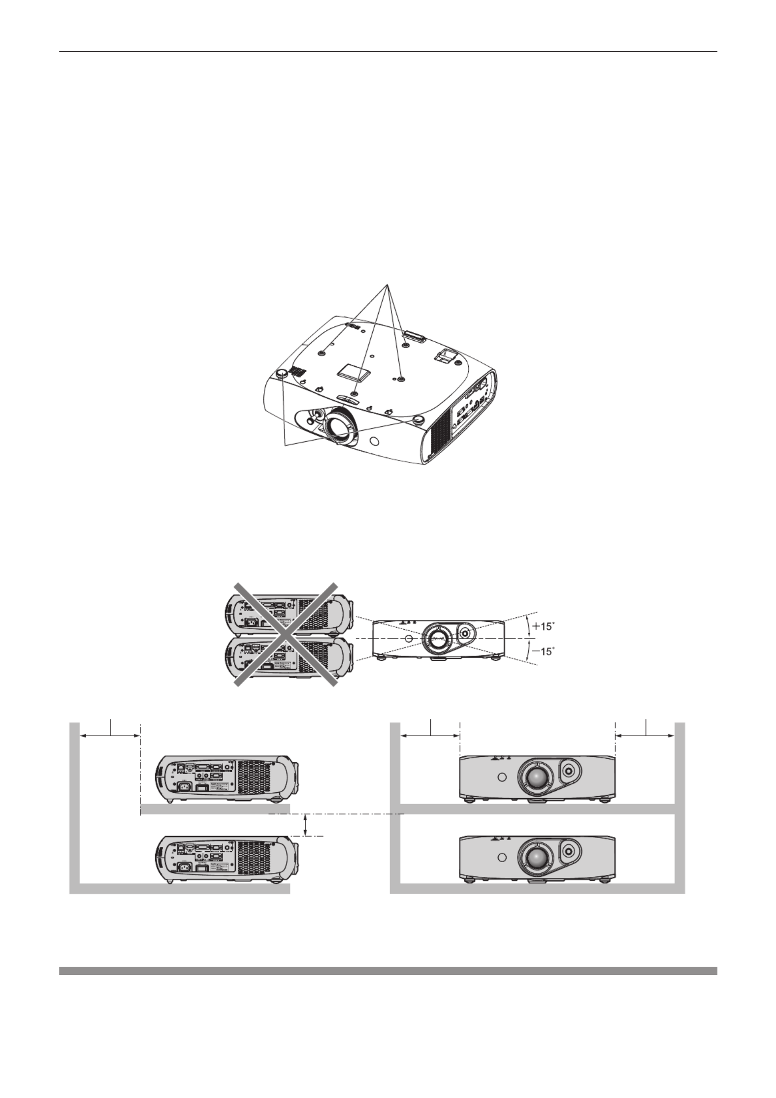
rDo not use the projector tilted to the right or left.
Using the projector at a vertical angle that exceeds 15° may reduce product life or result in malfunction.
Chapter 1 Preparation — Precautions for use
14 - ENGLISH
rWhen installing and using the projector at an angle that exceeds 30° vertically, set
[COOLING CONDITION] (x page 69).
Failure to observe this will result in malfunctions or shorten the life of the internal components.
rCautions when setting up the projector
fTo install and use the projector via a method that does not use the adjustable feet in a oor standing installation, x the
projector using the four screw holes for ceiling mounting (as shown in the gure).
(Screw diameter: M4, tapping depth inside the set: 10 mm (13/32"), torque: 1.25 ± 0.2 N·m)
Make a clearance of at least 12 mm (15/32") between the projector bottom and setting surface by inserting spacers (metallic)
etc. between them.
fUse the adjustable feet only for the oor standing installation and for adjusting the angle. Using it for other purposes may
damage the set.
6FUHZKROHVIRUFHLOLQJPRXQW0
$GMXVWDEOHIHHW
7KHSRVLWLRQVRIVFUHZKROHVIRUFHLOLQJPRXQWDQGDGMXVWDEOHIHHW
fDo not stack projectors on top of each other.
fDo not block the ventilation ports (intake and exhaust) of the projector.
fPrevent hot and cool air from the air conditioning system to blow directly to the ventilation ports (intake and exhaust) of the
projector.
PPRUORQJHU
PPRUORQJHU PPRUORQJHU
PPRUORQJHU
fDo not install the projector in a conned space.
When it is necessary to install the projector in a conned space, install the air conditioning or ventilation separately. Exhaust
heat may accumulate when the ventilation is not enough, triggering the protection circuit of the projector.
Security
When using this product, take safety measures against the following incidents.
fPersonal information being leaked via this product
fUnauthorized operation of this product by a malicious third party

Chapter 1 Preparation — Precautions for use
ENGLISH - 15
fInterfering or stopping of this product by a malicious third party
Take sufcient security measures. (x pages 84, 102)
fMake your password difcult to guess as much as possible.
fChange your password periodically.
fPanasonic Corporation or its afliate companies will never ask for your password directly. Do not divulge your password in
case you receive such inquiries.
fThe connecting network must be secured by a rewall, etc.
fSet a password for the web control and restrict the users who can log in.
DIGITAL LINK
“DIGITAL LINK” is a technology that uses a twisted-pair-cable to transmit video, audio, Ethernet, and serial control signals.
The projector supports the optional digital interface box (Model No.: ET-YFB100G), and the “XTP transmitter” of Extron
Electronics. For twisted-pair-cable transmitter of other manufacturers of which the operation has been veried with the
DIGITAL LINK compatible projector, refer to Panasonic website (http://panasonic.net/avc/projector/). Note that the verication
for devices of other manufacturers has been made for the items set by Panasonic Corporation, and not all the operations have
been veried. For operation or performance problems caused by the devices of other manufacturers, contact the respective
manufacturers.
Disposal
To dispose of the product, ask your local authorities or dealer for correct methods of disposal.
Cautions on use
rTo get a good picture quality
fIn order to view a beautiful image in higher contrast, prepare an appropriate environment. Draw curtains or blinds over
windows and turn off any lights near the screen to prevent outside light or light from indoor lamps from shining onto the
screen.
fThe high clarity projection lens is thermally affected by the light from the light source, making the focus unstable in the period
just after switching on the power. The focus stabilizes when an image is projected continuously for 30 minutes or more.
rDo not touch the surface of the projection lens with your bare hands.
If the surface of the projection lens becomes dirty from ngerprints or anything else, this will be magnied and projected onto
the screen.
rDLP chips
fThe DLP chips are precision-made. Note that in rare cases, pixels of high precision could be missing or always lit. Note that
such phenomena does not indicate malfunction.
fDirecting a high-power laser beam onto the lens surface can damage the DLP chips.
rLight source
The light source of the projector uses LED and lasers, and has the following characteristics.
fThe luminance of the light source will decrease by duration of usage.
The usage time until when the luminance of the light source decreases by half is approximately 20 000 hours. 20 000 hours
is the estimated duration, and it varies depending on individual differences and usage conditions.
If the light source goes off or the brightness reduces noticeably, ask your dealer about replacement of the light source unit.
rComputer and external device connections
fWhen connecting a computer or an external device, use power cords and shielded cables following instructions in this
manual.
fUse a commercial DVI-D cable with a ferrite core.

Chapter 1 Preparation — Precautions for use
16 - ENGLISH
Accessories
Make sure that the following accessories are provided with your projector. Numbers enclosed in < > show the number of
accessories.
Wireless remote control unit <1>
(N2QAYB000812)
Power cord <1>
(TXFSX01RXQZ)
CD-ROM <1>
(TXFQB02VLF1)
AA/R6 or AA/LR6 battery <2>
(For remote control unit)
Attention
fAfter unpacking the projector, discard the power cord cap and packaging material properly.
fUse the supplied power cord only with the projector.
fFor missing accessories, consult your dealer.
fStore small parts in an appropriate manner, and keep them away from small children.
Note
fThe model numbers of accessories are subject to change without prior notice.
Contents of the supplied CD-ROM
The contents of the supplied CD-ROM are as follows.
Instruction/list (PDF) Operating Instructions – Functional Manual
Multi Projector Monitoring & Control Software Operation Manual
Logo Transfer Software Operating Instructions
List of Compatible Projector
Models
This is a list of projectors that are compatible with the software
contained in the CD-ROM and their restrictions.
Software Multi Projector Monitoring &
Control Software (Windows)
This software allows you to monitor and control multiple
projectors connected to the LAN.
Logo Transfer Software
(Windows)
This software allows you to create original images, such as
company logos to be displayed when projection starts, and
transfer them to the projector.
Optional accessories
Optional accessories
(product name) Model No.
Ceiling mount bracket ET-PKR100H (for high ceilings), ET-PKR100S (for low ceilings)
Digital interface box ET-YFB100G
Note
fThe model numbers of optional accessories are subject to change without prior notice.

Chapter 1 Preparation — Start-up display
ENGLISH - 17
Start-up display
The initial setting screen is displayed when the projector is switched on for the rst time after purchase as well as when [ALL USER DATA]
(x page 80) in [INITIALIZE] is executed. Set them in accordance with circumstances.
In other occasions, you can change the settings by menu operations.
Note
fWhen the projector is used for the rst time, you may be required to adjust the lens zoom ring and focus ring of the projector ( x page 19)
to display the menu screen clearly.
Refer to “Adjusting the image” ( x page 34) for details.
Initial setting (display language)
Select the language to show on the screen. ( x page 57)
1) Press to select the display language.as
(17(5
,1,7,$/6(77,1*
6(/(&7
6(7
2) Press the <ENTER> button to proceed to the initial setting.
Initial setting (projector setup)
Set each item.
1) Press to select an item.as
2) Press to switch the setting.qw
ENTER
INITIAL SETTING
SELECT CHANGE
SET
PROJECTION METHOD
COOLING CONDITION
SCREEN FORMAT
SCREEN POSITION
16:10
HIGH ALTITUDE MODE
SWITCH TO HIGH ALTITUDE MODE "ON" IF
OVER 1400m(4593Ft).
OFF
FRONT/FLOOR
FLOOR SETTING
fRefer to the following page for details of each item.
[PROJECTION METHOD] ( x page 68)
[COOLING CONDITION] (x page 69)
[SCREEN FORMAT] ( x page 59)
[SCREEN POSITION] ( x page 59)
[HIGH ALTITUDE MODE] (x page 69)
3) Press the <ENTER> button.
fFix the setting value to complete the initial setting.
Note
fIf you press the <RETURN> button in the initial setting (display language) screen, you can go back to the initial setting (display language)
screen.
f[SCREEN FORMAT] and [SCREEN POSITION] can only be set on PT-RW330E.
fTo continue operations after completed the initial setting (projector setup), refer to “Selecting the input signal” ( x page 34).
fBy default, the time zone of the projector is set to +09:00 (Japan and Korean Standard Time). Change the setting in the [PROJECTOR
SETUP] menu → [DATE AND TIME] → [TIME ZONE] to the time zone of the region where you use the projector.

Chapter 1 Preparation — About your projector
18 - ENGLISH
About your projector
Remote control
$WWDFKDVWUDSDFFRUGLQJWR
XVDJHFRQGLWLRQ
)URQW S7R
1 Remote control indicator
Flashes if any button in the remote control is pressed.
2 Power < v/b> button
Sets the projector to the standby mode when the <MAIN
POWER> switch on the projector is set to <ON>. Also sets the
projector in projection mode when the power is switched off
(standby mode).
3 Input selection (<COMPUTER>, <DVI-I>, <VIDEO>, <DIGITAL
LINK>, <HDMI>) buttons
Switches the input signal to project. ( x page 37)
Also used to set the ID number of the remote control and
security password. ( x page 21)
4 <MENU> button
Displays the main menu. ( x page 40)
5 <FREEZE> button
Used to pause a video and mute the audio. ( x page 36)
6 <DEFAULT> button
Resets the content of the sub-menu to the factory default.
(x page 41)
7 <FUNC1> to <FUNC3> buttons
You can assign a frequently used operation as a shortcut button.
(x page 38)
8 <ID SET> button
Sets the ID number of the remote control to use for a system
using multiple projectors. ( x page 21)
9 <ID ALL> button
Use to simultaneously control all the projectors with one remote
control for a system using multiple projectors. ( x page 21)
10 <AUTO SETUP> button
Automatically adjusts the image display position while projecting
the image.
[PROGRESS] is displayed on the screen while the image is
adjusted automatically. ( x page 37)
11 asqw buttons/<RETURN> button/<ENTER> button
Used to navigate through the menu screen.
Also used to enter a [SECURITY] password or character input.
12 <AV MUTE> button
Use to temporarily turn off the audio and video. ( x page 36)
13 <ECO> button
Displays the setting screen related to ECO management.
(x page 38)
14 <VOLUME+>/<VOLUME
-
> button
Adjusts the audio output volume. ( x page 38)
15 Strap hole
16 Remote control signal transmitter
Attention
fDo not drop the remote control.
fAvoid contact with liquids or moisture.
fDo not attempt to modify or disassemble the remote control.
fWhen attaching the strap to the remote control, hold the strap to prevent it from swinging.
Note
fThe remote control can be used within a distance of about 15 m (49'2") if pointed directly at the remote control receiver. The remote control
can control at angles of up to ±15° vertically and ±30° horizontally, but the effective control range may be reduced.
fIf there are any obstacles between the remote control and the remote control signal receiver, the remote control may not operate properly.
fThe signal will be reected off the screen. However, the operating range may be limited from light reection loss due to the screen material.
fIf the remote control signal receiver directly receives strong light, such as uorescent light, the remote control may not operate properly. Use
it in a place distant from the light source.
fThe power indicator <ON (G)/STANDBY (R)> will ash if the projector receives a remote control signal.

Chapter 1 Preparation — About your projector
ENGLISH - 19
Projector body
)URQW
)URQW
)URQW 6LGH
5HDU
)URQW
%RWWRP
1 Power indicator <ON (G)/STANDBY (R)>
Displays the status of the power.
2 Light source indicator <LIGHT>
Displays the status of the light source.
3 Temperature indicator <TEMP>
Displays the internal temperature status.
4 RISK GROUP 3 label
The following label is attached to the top surface of the
projector.
TQFX340
5 Adjustable feet
Adjusts the projection angle.
6 Remote control signal receiver (front)
7 Projection lens
8 Lens shift lever
Adjusts the projection position.
9 Air intake port
10 Air exhaust port
11 Remote control signal receiver (rear)
12 Security slot
This security slot is compatible with the Kensington security
cables.
13 Connecting terminals ( x page 20)
14 <AC IN> terminal
Connect the supplied power cord.
15 <MAIN POWER> switch
Turns on/off the main power.
16 Focus ring
Adjusts the focus.
17 Zoom ring
Adjusts the zoom.
18 Control panel ( x page 20)
19 Burglar hook port
You can attach a commercial burglar prevention cable.

Chapter 1 Preparation — About your projector
20 - ENGLISH
rControl panel
3
4
1
2
1 Power < v/b> button
Sets the projector to the state where the projector is switched
off (standby mode) when the <MAIN POWER> switch on the
projector is set to <ON> and in projection mode. Also sets the
projector in projection mode when the power is switched off
(standby mode).
2 <MENU> button
Displays the main menu.
3 <INPUT SELECT> button
Switches the input signal to project. ( x page 37)
4 asqw buttons/<RETURN> button/<ENTER> button
Used to navigate through the menu screen.
Also used to enter a [SECURITY] password or character input.
rConnecting terminals
1 2 3 4 5
876
1 <DIGITAL LINK/LAN> terminal
This is the LAN terminal to connect to the network. This is
also used when connecting an audio and video signal sending
device via the LAN terminal.
2 <HDMI IN> terminal
This is the terminal to input HDMI signals.
3 <DVI-I IN> terminal
This is the terminal to input DVI-D and DVI-A signals (RGB
signals or YC BCR/YPBPR).
4 <COMPUTER IN> terminal
This is the terminal to input RGB or YC BCR/YPBPR signals from
a computer.
5 <VIDEO IN> terminal
This is the terminal to input video signals.
6 <AUDIO IN> terminal
This is the terminal to input audio signals.
7 <VARIABLE AUDIO OUT> terminal
This is the terminal to output audio signals input to the projector.
8 <SERIAL IN> terminal
This is the RS-232C compatible terminal to externally control
the projector by connecting a computer.
Attention
fWhen a LAN cable is directly connected to the projector, the network connection must be made indoors.
Chapter 1 Preparation — Using the remote control
ENGLISH - 21
Using the remote control
Inserting and removing the batteries
(i)
(ii)
Fig. 1 Fig. 2
1) Open the cover. (Fig. 1)
2) Insert the batteries and close the cover (insert the side first). (Fig. 2)m
fWhen removing the batteries, perform the steps in reverse order.
Setting the remote control ID numbers
When you use the system with multiple projectors, you can operate all the projectors simultaneously or each projector individually using single
remote control, if a unique ID number is assigned to each projector.
After setting the ID number of the projector, set same ID number on the remote control.
The factory default ID number of the projector is set to [ALL]. When using a single projector, press the <ID ALL> button on the
remote control. Also, you can control a projector if you press the <ID ALL> button on the remote control even if you do not know the
projector ID.
How to set
1) Press the <ID SET> button on the remote control.
2) Within five seconds, press the one-digit ID number set on the projector using the number (<1> - <6>)
buttons.
fIf you press the <ID ALL> button, you can control the projectors regardless of the ID number setting of the projector.
Attention
fSince the ID number of the remote control can be set without the projector, do not press the <ID SET> button carelessly. If the <ID SET>
button is pressed and no number (<1> - <6>) buttons are pressed within ve seconds, the ID number returns to its original value before the
<ID SET> button was pressed.
fThe ID number set on the remote control will be stored unless it is set again. However, it will be erased if the remote control is left with dead
batteries. Set the same ID number again when the batteries are replaced.
Note
fSet the ID number of the projector from the [PROJECTOR SETUP] menu → [PROJECTOR ID] ( x page 68).

22 - ENGLISH
Chapter 2 Getting Started
This chapter describes things you need to do before using the projector such as the setup and connections.

Chapter 2 Getting Started — Setting up
ENGLISH - 23
Setting up
Projection method
You can use the projector with any of the following four projection methods. Select the appropriate method depending on the environment.
Mounting on the ceiling and projecting forward Setting on a desk/oor and projecting from rear
(Using the translucent screen)
Menu item *1 Method Menu item *1 Method
[PROJECTION METHOD] [PROJECTION METHOD][FRONT/CEILING] [REAR/FLOOR]
[COOLING CONDITION] [COOLING CONDITION][CEILING SETTING] [FLOOR SETTING]
Mounting on the ceiling and projecting from rear
(Using the translucent screen)
Setting on a desk/oor and projecting forward
Menu item *1 Method Menu item *1 Method
[PROJECTION METHOD] [PROJECTION METHOD][REAR/CEILING] [FRONT/FLOOR]
[COOLING CONDITION] [COOLING CONDITION][CEILING SETTING] [FLOOR SETTING]
*1 For menu item details, refer to the [PROJECTOR SETUP] menu → [PROJECTION METHOD] ( x page 68) and [COOLING CONDITION]
(x page 69).
Parts for ceiling mount (optional)
You can install the projector on the ceiling using the optional ceiling mount bracket (Model No.: ET-PKR100H (for high ceilings), or
ET-PKR100S (for low ceilings).
fUse only the ceiling mount brackets specied for this projector.
fRefer to the installation manual for the ceiling mount bracket when installing and setting up the bracket and the projector.
Attention
fTo ensure projector performance and security, installation of the ceiling mount bracket must be carried out by your dealer or a qualied
technician.

Chapter 2 Getting Started — Setting up
24 - ENGLISH
Screen size and throw distance
Refer to the following gures and table describing projection distances to install the projector. Image size and image position can be adjusted
in accordance with the screen size and screen position.
6'
//: /7
//: /7
6: 6+
6+
6:
3URMHFWLRQVFUHHQ
6FUHHQ
6FUHHQ
L (LW/LT)
*1 Projection distance (m)
SH Image height (m)
SW Image width (m)
SD Image diagonal size (m)
*1 LW: Minimum projection distance
LT: Maximum projection distance
Attention
fBefore setting up, read “Precautions for use” ( x page 13).
fDo not use the projector and the high-powered laser equipment in the same room.
fHitting of a laser beam on to the lens can damage the DLP chips.
Projection distance
For PT-RZ370E
(The dimensions of the following table contain a slight error.)
(Unit: m)
Projection screen
size 4:3 aspect ratio 16:9 aspect ratio 16:10 aspect ratio
Diagonal (SD)
Min. projection
distance
(LW)
Max. projection
distance
(LT)
Min. projection
distance
(LW)
Max. projection
distance
(LT)
Min. projection
distance
(LW)
Max. projection
distance
(LT)
1.02 (40") 1.55 (5.10') 3.16 (10.39') 1.26 (4.13') 2.58 (8.47') 1.36 (4.48') 2.79 (9.16')
1.27 (50") 1.95 (6.42') 3.97 (13.02') 1.59 (5.21') 3.23 (10.62') 1.72 (5.65') 3.50 (11.49')
1.52 (60") 2.36 (7.74') 4.77 (15.66') 1.91 (6.29') 3.89 (12.77') 2.07 (6.82') 4.21 (13.81')
1.78 (70") 2.76 (9.06') 5.57 (18.29') 2.24 (7.37') 4.54 (14.92') 2.43 (7.99') 4.92 (16.14')
2.03 (80") 3.16 (10.39') 6.37 (20.92') 2.57 (8.45') 5.20 (17.07') 2.79 (9.15') 5.62 (18.46')
2.29 (90") 3.56 (11.71') 7.18 (23.55') 2.90 (9.53') 5.85 (19.22') 3.14 (10.32') 6.33 (20.79')
2.54 (100") 3.97 (13.03') 7.98 (26.19') 3.23 (10.61') 6.51 (21.37') 3.50 (11.49') 7.04 (23.11')
3.05 (120") 4.77 (15.67') 9.58 (31.45') 3.89 (12.77') 7.82 (25.67') 4.21 (13.82') 8.46 (27.76')
3.81 (150") 5.98 (19.63') 11.99 (39.35') 4.88 (16.01') 9.79 (32.13') 5.28 (17.32') 10.59 (34.74')
5.08 (200") 7.99 (26.24') 16.00 (52.51') 6.52 (21.41') 13.07 (42.88') 7.05 (23.16') 14.13 (46.37')
6.35 (250") 10.01 (32.85') 20.01 (65.67') 8.17 (26.80') 16.34 (53.63') 8.83 (28.99') 17.67 (57.99')
7.62 (300") 12.02 (39.45') 24.03 (78.83') 9.81 (32.20') 19.62 (64.39') 10.61 (34.83') 21.22 (69.62')
Chapter 2 Getting Started — Setting up
ENGLISH - 25
For PT-RW330E
(The dimensions of the following table contain a slight error.)
(Unit: m)
Projection screen
size 4:3 aspect ratio 16:9 aspect ratio 16:10 aspect ratio
Diagonal (SD)
Min. projection
distance
(LW)
Max. projection
distance
(LT)
Min. projection
distance
(LW)
Max. projection
distance
(LT)
Min. projection
distance
(LW)
Max. projection
distance
(LT)
1.02 (40") 1.46 (4.81') 2.99 (9.81') 1.32 (4.53') 2.71 (8.90') 1.29 (4.23') 2.63 (8.65')
1.27 (50") 1.84 (6.06') 3.75 (12.30') 1.67 (5.49') 3.40 (11.15') 1.62 (5.33') 3.30 (10.85')
1.52 (60") 2.22 (7.31') 4.50 (14.79') 2.01 (6.62') 4.08 (13.41') 1.96 (6.43') 3.97 (13.05')
1.78 (70") 2.60 (8.56') 5.26 (17.27') 2.36 (7.75') 4.77 (15.67') 2.29 (7.54') 4.64 (15.24')
2.03 (80") 2.99 (9.81') 6.02 (19.76') 2.71 (8.89') 5.46 (17.93') 2.63 (8.64') 5.31 (17.44')
2.29 (90") 3.37 (11.06') 6.78 (22.25') 3.05 (10.02') 6.15 (20.19') 2.97 (9.74') 5.98 (19.64')
2.54 (100") 3.75 (12.30') 7.54 (24.74') 3.40 (11.15') 6.84 (22.45') 3.30 (10.85') 6.65 (21.83')
3.05 (120") 4.51 (14.80') 9.05 (29.71') 4.09 (13.42') 8.21 (26.96') 3.98 (13.05') 7.99 (26.23')
3.81 (150") 5.65 (18.55') 11.33 (37.18') 5.12 (16.82') 10.28 (33.74') 4.98 (16.36') 10.00 (32.82')
5.08 (200") 7.55 (24.79') 15.12 (49.61') 6.85 (22.49') 13.72 (45.03') 6.66 (21.88') 13.35 (43.81')
6.35 (250") 9.46 (31.03') 18.91 (62.05') 8.58 (28.16') 17.16 (56.32') 8.35 (27.39') 16.70 (54.80')
7.62 (300") 11.36 (37.28') 22.70 (74.49') 10.31 (33.83') 20.61 (67.61') 10.03 (32.91') 20.05 (65.78')
Projection distance formulas
To use a screen size not listed in this manual, check the screen size SD (m) and use the following formula to calculate projection distance.
The unit of the formula is m. (The values of the following calculation results contain slight error.)
For PT-RZ370E
4:3 aspect ratio 16:9 aspect ratio 16:10 aspect ratio
Screen size Height (SH) = SD x 0.6 = SD x 0.490 = SD x 0.530
Screen size Width (SW) = SD x 0.8 = SD x 0.872 = SD x 0.848
Min. projection distance (LW) = 1.5854 x SD - 0.0544 = 1.2955 x SD - 0.0544 = 1.4004 x SD - 0.0544
Max. projection distance (LT) = 3.1589 x SD - 0.0408 = 2.5812 x SD - 0.0408 = 2.7904 x SD - 0.0408
For PT-RW330E
4:3 aspect ratio 16:9 aspect ratio 16:10 aspect ratio
Screen size Height (SH) = SD x 0.6 = SD x 0.490 = SD x 0.530
Screen size Width (SW) = SD x 0.8 = SD x 0.872 = SD x 0.848
Min. projection distance (LW) = 1.4984 x SD - 0.0542 = 1.3604 x SD - 0.0542 = 1.3236 x SD - 0.0542
Max. projection distance (LT) = 2.9851 x SD - 0.0407 = 2.7102 x SD - 0.0407 = 2.6369 x SD - 0.0407
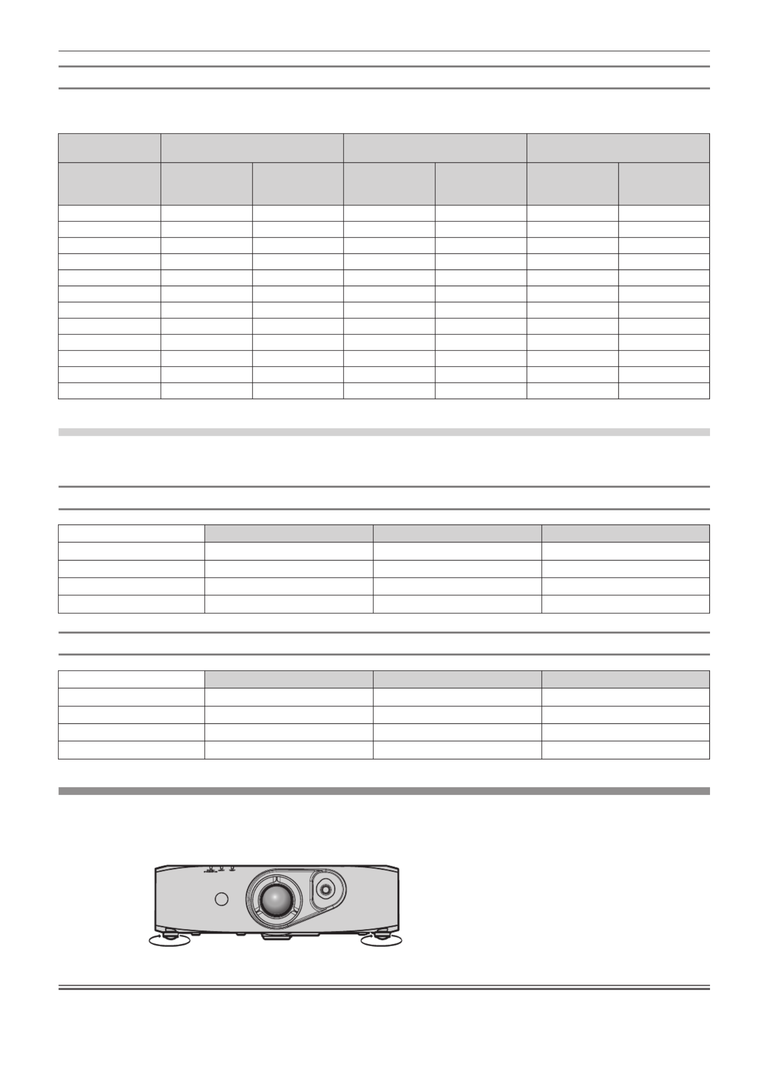
Adjusting adjustable feet
Install the projector on a at surface so that the front of the projector is parallel to the screen surface and the projection screen is rectangular.
If the screen is tilted downward, the projection screen can be adjusted to be rectangular by adjusting the adjustable feet. The adjustable feet
can also be used to adjust the projector to be level when it is tilted in a horizontal direction.
Extend the adjustable feet by rotating in the direction shown in the gure and retract by rotating in the opposite direction.
$GMXVWDEOHDPRXQW
)URQWDGMXVWDEOHIHHW$SSUR[PP
Attention
fWhen adjusting the adjustable feet when the light source is on, make sure that your hands do not block the intake and exhaust. ( x page 19)
fWhen there is trapezoidal distortion, execute the [POSITION] menu → [KEYSTONE] (x page 53).

Chapter 2 Getting Started — Connecting
26 - ENGLISH
Connecting
Before connecting
fBefore connecting, carefully read the operating instructions for the external device to be connected.
fTurn off the power of all devices before connecting cables.
fTake note of the following points before connecting the cables. Failure to do so may result in malfunctions.
gWhen connecting a cable to a device connected to the projector or the projector itself, touch any nearby metallic objects to eliminate static
electricity from your body before performing work.
gDo not use unnecessarily long cables to connect to a device connected to the projector or to the projector body. The longer the cable, the
more it is susceptible to noise. Since using a cable while it is wound makes it act like an antenna, it is more susceptible to noise.
gWhen connecting cables, connect GND rst, then insert the connecting terminal of the connecting device in a straight manner.
fAcquire any connection cable necessary to connect the external device to the system that is either not supplied with the device or not
available as an option.
fVideo signals containing too much jitter may cause the images on the screen to randomly wobble or wafture. In this case, a time base
corrector (TBC) must be connected.
fThe projector accepts video signals, analog RGB signals (synchronous signals are TTL level), and digital signals.
fSome computer models are not compatible with the projector.
fUse a cable compensator when you connect devices to the projector using long cables. Otherwise the image may not display properly.
fRefer to “List of compatible signals” ( x page 120) for the types of video signals that can be used with the projector.
<COMPUTER IN> terminal pin assignments and signal names
Outside view Pin No. Signal name Pin No. Signal name
(10)
(6)
(11) (15)
(1) (5)
(1) R/P R(9) ―
(2) (10)G/Y GND
(3) B/P B(11) GND
(4) (12)― DDC data
(5) (13)GND SYNC/HD
(6) (14)GND VD
(7) (15)GND DDC clock
(8) GND
<DVI-I IN> terminal pin assignments and signal names
Outside view Pin No. Signal name Pin No. Signal name
(9)
(17)(24)
(1)(8)
(16)
C1
C4
C2
C3
C5
(1) T.M.D.S data 2
-
(16) Hot plug detection
(2) T.M.D.S data 2+ T.M.D.S data 0(17)
-
(3) T.M.D.S data 2/4 shield T.M.D.S data 0+(18)
(4) (19)― T.M.D.S data 0/5 shield
(5) (20)― ―
(6) (21)DDC clock ―
(7) (22)DDC data T.M.D.S clock shield
(8) (23)Analog VD T.M.D.S clock+
(9) T.M.D.S data 1
-
(24) T.M.D.S clock
-
(10) T.M.D.S data 1+ Analog R/PC1 R
(11) T.M.D.S data 1/3 shield Analog G/G SYNC/YC2
(12) C3― Analog B/P B
(13) C4― Analog HD/SYNC
(14) C5+5 V Analog GND
(15) GND

Chapter 2 Getting Started — Connecting
28 - ENGLISH
Connecting example: Computers
&RPSXWHU &RPSXWHU
&RPSXWHU
&RPSXWHU
&RQWUROFRPSXWHU
&RQWUROFRPSXWHU
Attention
fWhen connecting the projector to a computer or an external device, use the power cord supplied with each device and commercially
available shielded cables.
fUse a commercial DVI-D cable with a ferrite core.
Note
fFor an HDMI cable, use an HDMI High Speed cable that conforms to HDMI standards. If a cable that does not conform to HDMI standards
is used, images may be interrupted or not displayed, or the projector may not function properly.
fThe <HDMI IN> terminal of the projector can be connected to an external device with an DVI terminal by using an HDMI/DVI conversion
cable, but some devices may not project the image properly or otherwise function properly. (
x page 62)
fThe <DVI-I IN> terminal (for digital input) supports single link only.
fFor signals that the projector can project, refer to “List of compatible signals” (
x page 120).
fIf you operate the projector using the computer with the resume feature (last memory), you may have to reset the resume feature to operate
the projector.
fDuring DVI digital signal input, EDID settings may be necessary depending on the external devices to be connected. (
x page 61)
fIf the [AUDIO IN SELECT] settings are incorrect, the projector may not output audio or otherwise function properly. (
x page 77)
Connecting example: Twisted-pair-cable transmitter
Twisted-pair-cable transmitters such as the optional digital interface box (Model No.: ET-YFB100G) use twisted-pair-cables to transmit input
video, audio, Ethernet, and serial signals, and the projector can input those digital signals to the <DIGITAL LINK/LAN> terminal.
%OXUD\GLVFSOD\HU
+'0,FDEOH
FRPPHUFLDOO\DYDLODEOH
&RQWUROFRPSXWHU
3URMHFWRUFRQQHFWLQJWHUPLQDOV
([DPSOHRIWZLVWHGSDLUFDEOHWUDQVPLWWHU
&RPSXWHU
&RPSXWHUFDEOH
FRPPHUFLDOO\DYDLODEOH
9&5
+XE

Chapter 2 Getting Started — Connecting
ENGLISH - 29
Attention
fAlways use one of the following when connecting a VCR.
gA VCR with built-in time base corrector (TBC)
gA time base corrector (TBC) between the projector and the VCR
fIf nonstandard burst signals are connected, the image may be distorted. In such case, connect the time base corrector (TBC) between the
projector.
fUse a commercial HDMI/DVI conversion cable with a ferrite core.
fAsk a qualied technician or your dealer to install the cable wiring for a twisted-pair-cable transmitter and the projector connection. Image
and sound may be disrupted if cable transmission characteristics can not be obtained due to inadequate installation.
fFor the LAN cable between a twisted-pair-cable transmitter and the projector, use a cable that meets the following criteria:
gCompatible with CAT5e or higher
gShielded type (including connectors)
gStraight-through
gSingle wire
fWhen laying cables between a twisted-pair-cable transmitter and the projector, check that cable characteristics are compatible with CAT5e
or higher using tools such as a cable tester or cable analyzer.
When using a relay connector midway, include it in the measurement.
fDo not use a hub between a twisted-pair-cable transmitter and the projector.
fWhen connecting to the projector using a twisted-pair-cable transmitter (receiver) of other company, do not place another twisted-pair-
cable transmitter in between the twisted-pair-cable transmitter of other company and the projector. This may cause sound and image to be
disrupted.
fDo not pull cables forcefully. Also, do not bend or fold cables unnecessarily.
fTo reduce noise, stretch out the cables between the twisted-pair-cable transmitter and the projector without any loops as much as possible
before setting them up and using them.
fLay the cables between a twisted-pair cable transmitter and the projector away from other cables, particularly power cables.
fWhen installing multiple cables, run them side by side along the shortest distance possible without bundling them together.
fAfter laying the cables, conrm that the [SIGNAL QUALITY] value is displayed in green to indicate normal quality using the [NETWORK]
menu → [DIGITAL LINK STATUS]. (x page 88)
Note
fFor an HDMI cable, use an HDMI High Speed cable that conforms to HDMI standards. If a cable that does not conform to HDMI standards
is used, images may be interrupted or may not be displayed.
fThe projector does not support VIERA Link (HDMI).
fThe maximum transmission distance between the twisted-pair-cable transmitter and the projector is 100 m (328'1"). If this distance is
exceeded, image and sound may be disrupted and may cause a malfunction in LAN communication. Please note that we do not support the
use of the projector outside the maximum transmission distance.
fFor twisted-pair-cable transmitter of other manufacturers of which the operation has been veried with the DIGITAL LINK compatible
projector, refer to Panasonic website (http://panasonic.net/avc/projector/). Note that the verication for devices of other manufacturers
has been made for the items set by Panasonic Corporation, and not all the operations have been veried. For operation or performance
problems caused by the devices of other manufacturers, contact the respective manufacturers.

30 - ENGLISH
Chapter 3 Basic Operations
This chapter describes basic operations to start with.

Chapter 3 Basic Operations — Switching on/off the projector
ENGLISH - 31
Switching on/off the projector
Connecting the power cord
Make sure that the supplied power cord is securely xed to the projector body to prevent it from being removed easily.
Conrm that the <MAIN POWER> switch is on the <OFF> side before connecting the power cord.
For details of power cord handling, refer to “Read this rst!” (
x page 2).
Attaching the power cord
1) Check the shapes of the <AC IN> terminal on the side of the projector body and the power cord
connector and insert the plug completely in the correct direction until you hear the hooks click in
place.
Removing the power cord
1) Confirm that the <MAIN POWER> switch of the main side is on the <OFF> side, and remove the power
plug from the outlet.
2) Remove the power cord connector from the <AC IN> terminal of the projector body while pressing the
side tabs.
Power indicator
Displays the status of the power. Check the <ON (G)/STANDBY (R)> status of the power indicator before operating the projector.
3RZHULQGLFDWRU21*67$1'%<5!

Chapter 3 Basic Operations — Switching on/off the projector
32 - ENGLISH
Indicator status Status
Off The main power is switched off.
Red
Flashing
The power is switched off (in standby mode). [STANDBY MODE] is set to [NORMAL].
Projection will start when the power <
v/b> button is pressed.
fThe projector may not operate when the temperature indicator <TEMP> is ashing.
(x page 108)
Lit
The power is switched off (in standby mode). [STANDBY MODE] is set to [ECO].
Projection will start when the power <
v/b> button is pressed.
fThe projector may not operate when the temperature indicator <TEMP> is ashing.
(x page 108)
Green Lit Projecting.
Note
fThe projector consumes power even in standby mode (the power indicator <ON (G)/STANDBY (R)> lights/ashes in red).
Refer to “Power consumption” (
x page 122) for the power consumption.
fThe power indicator <ON (G)/STANDBY (R)> ashes in green if a remote control signal is received.
fThe power indicator <ON (G)/STANDBY (R)> ashes in green slowly when the projector is in AV mute mode.
Switching on the projector
1)
3)
2)
3)
1) Connect the power plug to an outlet.
f(AC 100 V - 240 V 50 Hz/60 Hz)
2) Press the <ON> side of the <MAIN POWER> switch to turn on the power.
fThe power indicator <ON (G)/STANDBY (R)> lights/ashes in red, and the projector enters the standby mode.
3) Press the power < / > button.v b
fThe power indicator <ON (G)/STANDBY (R)> lights in green and the image is soon projected on the screen.
Note
fIf the projector is switched on at around 0 °C (32 °F), a warm-up period of approximately ve minutes may be necessary until an image is
displayed.
The temperature indicator <TEMP> lights during the warm-up period. When the warm-up is completed, the temperature indicator <TEMP>
turns off and the projection starts. Refer to “Managing the indicated problems” (
x page 108) for the indicator status.
fIf the operating environment temperature is low and warm-up takes more than ve minutes, the projector will judge that a problem has
occurred and the power will automatically be set to standby mode. If this happens, increase the operating environment temperature to 0 °C
(32 °F) or higher, turn off the main power, and then turn on the power again.
fIf the [PROJECTOR SETUP] menu → [ECO MANAGEMENT] → [STANDBY MODE] (x page 71) is set to [ECO], there may be a delay in
displaying when the power is turned on compared to when the setting is [NORMAL].
fWhen the power is turned or an input signal is switched, you may here a high-frequency driving sound. This is not a malfunction.
fIf the [PROJECTOR SETUP] menu → [INITIAL STARTUP] (
x page 73) is set to [LAST MEMORY] and the power is turned off by pressing
the <OFF> side of the <MAIN POWER> switch or by using the breaker directly while projecting at the last time of use, the power indicator
<ON (G)/STANDBY (R)> lights in green and projection starts after a while when the power is turned on by pressing the <ON> side of the
<MAIN POWER> switch with the power plug connected to the outlet, or when the breaker is turned on.

Chapter 3 Basic Operations — Projecting
34 - ENGLISH
Projecting
Check the external device connections (
x page 26) and the power cord connection (
x page 31), and turn on the projector (
x page 32)
to start projecting. Select the video for projection, and adjust appearance of the projected image.
Selecting the input signal
Select an input signal.
1) Press the input selection (<COMPUTER>, <DVI-I>, <VIDEO>, <DIGITAL LINK>, <HDMI>) buttons on the
remote control or the <INPUT SELECT> button on the control panel.
fThe image of the signal being input in the selected terminal is projected.
Attention
fImages may not be projected properly depending on the external device, or the blu-ray disc or DVD disc, to be played back.
Set the [PICTURE] menu → [SYSTEM SELECTOR] (x page 49).
fConrm the aspect ratio of the projection screen and the image, and switch to an optimum aspect ratio from the [POSITION] menu
→
[ASPECT] (x page 51).
Adjusting the image
/HQVVKLIWOHYHU
=RRPULQJ
)RFXVULQJ
)LJ )LJ
1) Adjust the projection angle.
fPlace the projector parallel to the screen and install on a at surface so that the projection screen is rectangular.
fIf the projector is tilted further downward than the screen, adjust the projection screen to be rectangular by extending the adjustable
feet.
fRefer to “Adjusting adjustable feet” (
x page 25) for details.
2) Release the lens shift lever lock by turning it counter-clockwise.
3) Adjust the lens shift. (Fig. 1)
fAdjust the projection position using the lens shift lever.
fRefer to “Adjustment range by the lens position shift (optical shift)” (
x page 35) for details.
4) Lock the lens shift lever by turning it clockwise.
5) Adjust the zoom and focus. (Fig. 2)
fAdjust by turning the zoom ring and focus ring.
Attention
fNote that your ngers may get caught between the lens and surrounding area when adjusting the zoom, depending on the position of the
hand holding the zoom ring.
Note
fIt is recommended that images are projected continuously for at least 30 minutes before the focus is adjusted.
fTurning the focus ring changes the projection screen size. Make ne adjustments again to the projection screen size by turning the zoom
ring.
fWhen there is trapezoidal distortion, execute the [POSITION] menu
→ [KEYSTONE] (x page 53).

Chapter 3 Basic Operations — Projecting
ENGLISH - 35
Adjustment range by the lens position shift (optical shift)
Perform the lens position shift within the adjustment range.
The focus may change when the lens position is shifted out of the adjustment range. This is because the movement of the lens is restricted to
protect the optical parts. Projection position can be adjusted with the optical axis shift based on the standard projection position in the range
shown in the following gures.
PT-RZ370E
+
+
99
3URMHFWLRQVFUHHQZLGWK+
6WDQGDUGSURMHFWLRQSRVLWLRQ
3URMHFWLRQVFUHHQKHLJKW9
PT-RW330E
++
99
3URMHFWLRQVFUHHQZLGWK+
6WDQGDUGSURMHFWLRQSRVLWLRQ
3URMHFWLRQVFUHHQKHLJKW9
* The numerical values in the preceding diagrams represent a case in which the projector is set on a desk/oor.
Note
fSet up the projector in front of the screen and adjust the lens shift lever to the center to obtain the optimal screen.

Chapter 3 Basic Operations — Operating with the remote control
ENGLISH - 37
Switching the input
The input for projection can be switched.
button
1) Press the input selection (<COMPUTER>, <DVI-I>, <VIDEO>, <DIGITAL LINK>, <HDMI>) buttons.
fThis operation can be also performed using the <INPUT SELECT> button on the control panel.
<COMPUTER> Switches to COMPUTER input.
<DVI-I> Switches to DVI-I input.
<VIDEO> Switches to VIDEO input.
<DIGITAL LINK> Switches to DIGITAL LINK input.
<HDMI> Switches to HDMI input.
Note
fWhen the optional digital interface box (Model No.: ET-YFB100G) is connected to the <DIGITAL LINK/LAN> terminal, the ET-YFB100G input
changes with each press of the <DIGITAL LINK> button.
For twisted-pair-cable transmitters of other companies, switch the input on the twisted-pair-cable transmitter after switching to DIGITAL LINK
input.
Using the Automatic setup function
The automatic setup function can be used to automatically adjust the resolution, clock phase, and image position when analog RGB signals
consisting of bitmap images such as computer signals are being input, or to automatically adjust the image position when DVI-D/HDMI signals
are input. Supplying images with bright white borders at the edges and high-contrast black and white characters is recommended when the
system is in automatic adjustment mode.
Avoid supplying images that include halftones or gradation, such as photographs and computer graphics.
button
1) Press the <AUTO SETUP> button.
f[COMPLETE] is displayed when it has completed without any problem.
Note
fThe clock phase may shift even if it has completed without any incident. In this case, adjust with the [POSITION] menu
→ [CLOCK PHASE]
(x page 52).
fIf an image with blurred edges or a dark image is input, [INCOMPLETE] may appear or adjustment may not be performed properly even
when [COMPLETE] appears. In this case, adjust the settings in the [ADVANCED MENU] menu
→ [INPUT RESOLUTION] (x page 55),
[POSITION] → [CLOCK PHASE] (
x page 52), [SHIFT] (
x page 50).
fAdjust special signals according to the [DISPLAY OPTION] menu
→ [AUTO SETUP] (x page 60).
fAutomatic adjustment may not work depending on the model of the computer.
fAutomatic adjustment may not work for a synchronization signal of C-SY or SYNC ON GREEN.
fImages may be disrupted for a few seconds during automatic adjustment, but it is not a malfunction.
fAdjustment is required for each input signal.
fAutomatic adjustment can be canceled by pressing the <RETURN> button or the <MENU> button during the automatic adjustment
operation.
fIf the automatic setup function is performed while moving images are being input, the adjustment may not be performed properly even for
an RGB signal for which automatic setup can be used. [INCOMPLETE] may appear, or adjustment may not be nished properly even if
[COMPLETE] appears.

Chapter 3 Basic Operations — Operating with the remote control
38 - ENGLISH
Using the Function button
Frequently used operations can be assigned to the buttons from <FUNC1> to <FUNC3> on the remote control to be used as simple shortcut
buttons.
buttons
1) Press the <FUNC1> to <FUNC3> buttons.
When assigning operations to the buttons from <FUNC1> to <FUNC3>
1) Press the <MENU> on the control panel or the remote control to display the menu items (main menu,
sub-menu, or details menu) you want to assign.
fRefer to “Navigating through the menu” (
x page 40) for the operation of the on-screen menu.
2) Press and hold any buttons from <FUNC1> to <FUNC3> for three seconds or more.
Note
fWhen settings are completed, F1, F2, or F3 is displayed on the left of the menu item (main menu, sub-menu, or details menu) assigned
when <FUNC1>, <FUNC2>, or <FUNC3> is set, respectively.
fTo clear the assigned functions, perform the [PROJECTOR SETUP] menu
→ [FUNCTION BUTTON] (x page 76).
Using the ECO management function
The setting screen related to the ECO management can be displayed.
button
1) Press the <ECO> button on the remote control.
Note
fRefer to the [PROJECTOR SETUP] menu
→ [ECO MANAGEMENT] (x page 69) for details.
Adjusting the volume
The audio output volume can be adjusted.
button
1) Press the <VOLUME+>/<VOLUME
-
> button on the remote control.
<VOLUME+> Increases the volume.
<VOLUME
-
>Decreases the volume.

ENGLISH - 39
Chapter 4 Settings
This chapter describes the settings and adjustments you can make using the on-screen menu.

Chapter 4 Settings — Menu navigation
40 - ENGLISH
Menu navigation
The on-screen menu (Menu) is used to perform various settings and adjustments of the projector.
Navigating through the menu
Operating procedure
button
1) Press the <MENU> button on the remote control or control panel.
fThe screen is displayed.[MAIN MENU]
(17(5
0$,10(18
3,&785(
326,7,21
$'9$1&('0(18
',63/$</$1*8$*(
',63/$<237,21
352-(&7256(783
7(67 77(513$
6,*1$//,67
6(&85,7<
1(7:25.
',*,7$//,1.
0(186(/(&7
68%0(18
2) Press to select an item from the main menu.as
fThe selected item is highlighted in yellow.
(17(5
0$,10(18
3,&785(
326,7,21
$'9$1&('0(18
',63/$</$1*8$*(
',63/$<237,21
352-(&7256(783
7(67 77(513$
6,*1$//,67
6(&85,7<
1(7:25.
',*,7$//,1.
0(186(/(&7
68%0(18
3) Press the <ENTER> button.
fThe sub-menu items of the selected main menu are displayed.
(17(5
326,7,21
6+,)7
1250$/$63(&7
=220
&/2&.3+$6(
.(<6721(
0(186(/(&7
68%0(18
4) Press to select a sub-menu, and press or the <ENTER> button to change or adjust settings.as qw
fMenu items switch in order as follows each time you press qw.
ABC
fFor some items, press qw to display an individual adjustment screen with a bar scale as shown below.
&2175$67
$'-867

Chapter 4 Settings — Menu navigation
42 - ENGLISH
Main menu item Page
[TEST PATTERN] 81
[SIGNAL LIST] 82
[SECURITY] 84
[NETWORK] 87
[DIGITAL LINK] 106
Sub-menu
The sub-menu of the selected main menu item is displayed, and you can set and adjust items in the sub-menu.
[PICTURE]
Sub-menu item Factory default Page
[PICTURE MODE] [GRAPHIC]*1 45
[CONTRAST] [0] 45
[BRIGHTNESS] [0] 46
[COLOR] [0] 46
[TINT] [0] 46
[COLOR TEMPERATURE] [DEFAULT] 46
[DAYLIGHT VIEW] [AUTO] 48
[SHARPNESS] [6]*1 48
[NOISE REDUCTION] [OFF]*1 48
[SYSTEM SELECTOR] [YPBPR]*1 49
*1 Depends on the signal input.
Note
fThe factory default settings may vary depending on the picture mode.
[POSITION]
Sub-menu item Factory default Page
[SHIFT] ― 50
[ASPECT] [NORMAL] 51
[ZOOM] ― 51
[CLOCK PHASE] [16]*1 52
[KEYSTONE] [0] 53
*1 Depends on the signal input.
[ADVANCED MENU]
Sub-menu item Factory default Page
[DIGITAL CINEMA REALITY] [AUTO]*1 54
[BLANKING] ― 54
[INPUT RESOLUTION] ― 55
[CLAMP POSITION] [24]*1 55
[FRAME RESPONSE] [NORMAL] 56
[RASTER POSITION] ― 56
*1 Depends on the signal input.

Chapter 4 Settings — Menu navigation
ENGLISH - 43
Note
fSub-menu items and factory default settings differ depending on the input terminal that is selected.
[DISPLAY LANGUAGE]
Details (x page 57)
[DISPLAY OPTION]
Sub-menu item Factory default Page
[COLOR MATCHING] [OFF] 58
[SCREEN SETTING]*1 ― 59
[AUTO SIGNAL] [OFF] 60
[AUTO SETUP] ― 60
[COMPUTER IN] ― 60
[DVI-I IN] ― 61
[HDMI IN] ― 62
[DIGITAL LINK IN] ― 62
[ON-SCREEN DISPLAY] ― 62
[CLOSED CAPTION SETTING] ― 64
[BACK COLOR] [BLUE] 65
[STARTUP LOGO] [DEFAULT LOGO] 65
[SUB MEMORY LIST] ― 66
[FREEZE] ― 66
[AV MUTE] ― 67
*1 Only for PT-RW330E.
[PROJECTOR SETUP]
Sub-menu item Factory default Page
[PROJECTOR ID] [ALL] 68
[PROJECTION METHOD] [FRONT/FLOOR] 68
[COOLING CONDITION] [FLOOR SETTING] 69
[HIGH ALTITUDE MODE] [OFF] 69
[ECO MANAGEMENT] ― 69
[SCHEDULE] [OFF] 71
[INITIAL STARTUP] [LAST MEMORY] 73
[STARTUP INPUT SELECT] [LAST USED] 73
[DIGITAL LINK INPUT] ― 74
[RS-232C] ― 74
[FUNCTION BUTTON] ― 76
[AUDIO SETTING] ― 76
[STATUS] ― 78
[DATE AND TIME] ― 78
[SAVE ALL USER DATA] ― 79
[LOAD ALL USER DATA] ― 79
[INITIALIZE] ― 80
[SERVICE PASSWORD] ― 80
Specyfikacje produktu
| Marka: | Panasonic |
| Kategoria: | projektor wideo |
| Model: | PT-RW330E |
| Kolor produktu: | Biały |
| Typ produktu: | Projektor o standardowym rzucie |
| Źródło zasilania: | Prąd przemienny |
| Wbudowany wyświetlacz: | Nie |
| Częstotliwość wejściowa AC: | 50 - 60 Hz |
| Napięcie wejściowe AC: | 100 - 240 V |
| Wysokość produktu: | 137 mm |
| Szerokość produktu: | 455 mm |
| Głębokość produktu: | 415 mm |
| Waga produktu: | 11000 g |
| W zestawie pilot zdalnego sterowania: | Tak |
| Poziom hałasu: | 35 dB |
| Zasięg obiektywu: | 2 - 3.4 |
| Ilość portów Ethernet LAN (RJ-45): | 1 |
| Umieszczenie: | Sufit |
| Zakres temperatur (eksploatacja): | 0 - 45 °C |
| Zakres wilgotności względnej: | 20 - 80 % |
| Współczynnik kontrastu (typowy): | 10000:1 |
| Natywne proporcje obrazu: | 16:10 |
| Możliwość przybliżenia: | Tak |
| Wi-Fi: | Nie |
| Pobór mocy w trybie czuwania: | 8 W |
| Wejscie Audio (L,P): | 1 |
| Przewodowa sieć LAN: | Tak |
| Zintegrowany czytnik kart: | Nie |
| Kompatybilność 3D: | Nie |
| Pobór mocy: | 460 W |
| Ilość portów HDMI: | 1 |
| Liczba portów VGA (D-Sub): | 1 |
| HDCP: | Tak |
| Wyście mocy ac: | Tak |
| Długość ogniskowa: | 21.5 - 43 mm |
| Wejście komponentu wideo (ypbpr/ycbcr): | 1 |
| Wyjście audio (prawe/lewe): | 1 |
| Obsługiwane tryby wideo: | 480i, 480p, 576i, 576p |
| Port DVI: | Tak |
| Obsługiwane proporcje obrazu: | 16:10 |
| Pełny HD: | Nie |
| System formatu sygnału analogowego: | NTSC, NTSC 4.43, PAL, PAL 60, PAL M, PAL N, SECAM |
| Ostrość: | Ręczny |
| Jasność projektora: | 3500 ANSI lumenów |
| Technologia projekcji: | DLP |
| Naturalna rozdzielczość projektora: | WXGA (1280x800) |
| Korekcja Keystone'a, poziom: | -40 - 40 ° |
| Jednorodność: | 90 % |
| Odległość projekcji: | - m |
| Kompatybilność rozmiaru ekranu: | 40 - 300 " |
| Żywotność źródła światła: | 20000 h |
| Stosunek padania: | 1.53 - 3.09:1 |
| Współczynnik zbliżenia: | 2.0:1 |
| Rodzaj zoomu: | Ręczny |
| Poziom hałasu (tryp ekonomiczn): | 29 dB |
Potrzebujesz pomocy?
Jeśli potrzebujesz pomocy z Panasonic PT-RW330E, zadaj pytanie poniżej, a inni użytkownicy Ci odpowiedzą
Instrukcje projektor wideo Panasonic

30 Sierpnia 2024
30 Sierpnia 2024
7 Czerwca 2024
7 Czerwca 2024
7 Czerwca 2024
7 Czerwca 2024
7 Czerwca 2024
7 Czerwca 2024
7 Czerwca 2024
7 Czerwca 2024
Instrukcje projektor wideo
- projektor wideo Sony
- projektor wideo Sharp
- projektor wideo Lenovo
- projektor wideo Philips
- projektor wideo Acer
- projektor wideo Epson
- projektor wideo Hisense
- projektor wideo Promethean
- projektor wideo Canon
- projektor wideo Viewsonic
- projektor wideo Asus
- projektor wideo D-Link
- projektor wideo Blaupunkt
- projektor wideo Salora
- projektor wideo Casio
- projektor wideo HP
- projektor wideo Prixton
- projektor wideo Kodak
- projektor wideo Dell
- projektor wideo Eurolite
- projektor wideo Ricoh
- projektor wideo Pyle
- projektor wideo Kindermann
- projektor wideo OKI
- projektor wideo Mitsubishi
- projektor wideo RCF
- projektor wideo XGIMI
- projektor wideo NEC
- projektor wideo Sanyo
- projektor wideo Optoma
- projektor wideo Barco
- projektor wideo 3M
- projektor wideo Nebula
- projektor wideo Anker
- projektor wideo Hitachi
- projektor wideo BenQ
- projektor wideo Adj
- projektor wideo Miroir
- projektor wideo Stairville
- projektor wideo Planar
- projektor wideo Speaka
- projektor wideo InFocus
- projektor wideo Vivitek
- projektor wideo Vankyo
- projektor wideo EKO
- projektor wideo Christie
Najnowsze instrukcje dla projektor wideo

25 Września 2024
25 Września 2024

19 Września 2024
16 Września 2024
16 Września 2024
16 Września 2024
16 Września 2024

16 Września 2024
14 Września 2024
14 Września 2024