Instrukcja obsługi Linksys LAPAC1750PRO-EU
Linksys
Punkt dostępu
LAPAC1750PRO-EU
Przeczytaj poniżej 📖 instrukcję obsługi w języku polskim dla Linksys LAPAC1750PRO-EU (121 stron) w kategorii Punkt dostępu. Ta instrukcja była pomocna dla 9 osób i została oceniona przez 2 użytkowników na średnio 4.5 gwiazdek
Strona 1/121

LAPAC1750PRO
User Guide

ii
Table of ContentsLAPAC1750PRO Access Point Software User Manual
ii
Section 1: Getting Started 1. . . . . . . . . . . . . . . . . . . . . .
Administrator’s Computer Requirements . . . . . . . . . . . . . . .1
Wireless Client Requirements. . . . . . . . . . . . . . . . . . . . . . .2
Online Help, Supported Browsers, and Limitations . . . . . . . . .2
Dynamic and Static IP Addressing on the AP . . . . . . . . . . . . .3
Installing the Access Point . . . . . . . . . . . . . . . . . . . . . . . . .3
Configuring the Ethernet Settings. . . . . . . . . . . . . . . . . . . .5
Configuring IEEE 802.1X Authentication . . . . . . . . . . . . . . . .6
Configuring Security on the Wireless Access Point . . . . . . . . .6
Section 2: Viewing Access Point System Status . . . . . . . . 7
System Summary . . . . . . . . . . . . . . . . . . . . . . . . . . . . . .7
Network Interfaces . . . . . . . . . . . . . . . . . . . . . . . . . . . . .8
Radio Statistics . . . . . . . . . . . . . . . . . . . . . . . . . . . . . . . 10
Workgroup Bridge . . . . . . . . . . . . . . . . . . . . . . . . . . . . . 13
Associated Client. . . . . . . . . . . . . . . . . . . . . . . . . . . . . . 13
TSPEC Client Associations . . . . . . . . . . . . . . . . . . . . . . . . 15
TSPEC Status and Statistics . . . . . . . . . . . . . . . . . . . . . . . 16
TSPEC AP Statistics . . . . . . . . . . . . . . . . . . . . . . . . . . . . 17
Email Alert Status . . . . . . . . . . . . . . . . . . . . . . . . . . . . . 18
System Log . . . . . . . . . . . . . . . . . . . . . . . . . . . . . . . . . 18
Section 3: Configuring the Access Point . . . . . . . . . . . . .19
Administration . . . . . . . . . . . . . . . . . . . . . . . . . . . . . . . 19
LAN . . . . . . . . . . . . . . . . . . . . . . . . . . . . . . . . . . . . . . 29
Wireless . . . . . . . . . . . . . . . . . . . . . . . . . . . . . . . . . . . 33
Security. . . . . . . . . . . . . . . . . . . . . . . . . . . . . . . . . . . . 63
QoS and Access Control . . . . . . . . . . . . . . . . . . . . . . . . . 66
SNMP . . . . . . . . . . . . . . . . . . . . . . . . . . . . . . . . . . . . . 81
Captive Portal. . . . . . . . . . . . . . . . . . . . . . . . . . . . . . . . 88
Cluster . . . . . . . . . . . . . . . . . . . . . . . . . . . . . . . . . . . 101
Section 4: Maintenance of the Access Point . . . . . . . . . 110
Maintenance . . . . . . . . . . . . . . . . . . . . . . . . . . . . . . . 110
Diagnostics . . . . . . . . . . . . . . . . . . . . . . . . . . . . . . . . 114
Table of Contents

1
Section 1: Getting StartedLAPAC1750PRO Access Point Software User Manual
1
Section 1: Getting Started
The LAPAC1750PRO Access Point provides continuous, high-speed access
between wireless devices and Ethernet devices. It is an advanced, standards-
based solution for wireless networking in businesses of any size. The access point
(AP) enables wireless local area network (WLAN) deployment while providing
state-of-the-art wireless networking features.
The access point works in Standalone Mode, which means it is an individual
access point in your network. You manage the device through a Web-based user
interface (UI) or SNMP (Simple Network Management Protocol.
This document describes how to perform the setup, management, and
maintenance of the access point in Standalone Mode.
Before you power on a new access point, review the following sections to
check required hardware and software components, client configurations, and
compatibility issues. Make sure you have everything you need for a successful
launch and test of your new or extended wireless network.
This section contains the following topics:
• Administrator’s Computer Requirements
• Wireless Client Requirements
• Online Help, Supported Browsers, and Limitations
• Dynamic and Static IP Addressing
• Installing the Access Point
• Configuring the Ethernet Settings
• Configuring IEEE 802.1X Authentication
• Configuring Security on the Access Point
To manage the access point by using the Web interface, the AP needs an IP
address. If you use VLANs or IEEE 802.1X Authentication (port security) on your
network, you might need to configure additional settings on the AP before it can
connect to the network.
NOTE:
The access point is not designed to function as a gateway to the Internet.
To connect your WLAN to other LANs or the Internet, you need a gateway
device.
Administrator’s Computer Requirements
The following table describes the minimum requirements for the administrator’s
computer for configuration and administration of the access point through a
Web-based user interface (UI).
Table 1: Requirements for the Administrator’s Computer
Required Software or
Component
Description
Ethernet Connection to
the Access Point
The computer used to configure the first access
point must be connected to the access point by
an Ethernet cable.
Wireless Connection to
the Network
After initial configuration and launch of the first
access point on your new wireless network, you
can make subsequent configuration changes
through the Administration Web pages using a
wireless connection to the internal network. For
wireless connection to the access point, your
administration device will need Wi-Fi capability
similar to that of any wireless client: a portable
or built-in Wi-Fi client adapter that supports one
or more of the IEEE 802.11 modes in which you
plan to run the access point.

6
Section 1: Getting StartedLAPAC1750PRO Access Point Software User Manual
Configuring IEEE 802.1X Authentication
On networks that use IEEE 802.1X, port-based network access control,
a supplicant (client) cannot gain access to the network until the 802.1X
authenticator grants access. If your network uses 802.1X, you must configure
802.1X authentication information that the AP can supply to the authenticator.
If your network uses IEEE 802.1X see “802.1X Supplicant” on page 65 for
information about how to configure 802.1X by using the Web interface.
Verifying the Installation
Make sure the access point is connected to the LAN and associate some wireless
clients with the network. Once you have tested the basics of your wireless
network, you can enable more security and fine-tune the AP by modifying
advanced configuration features.
1. Connect the access point to the LAN.
•If you configured the access point and administrator PC by connecting
both into a network hub, then your access point is already connected to
the LAN. The next step is to test some wireless clients.
•If you configured the access point by using a direct cable connection
from your computer to the access point, do the following procedures:
a. Disconnect the cable from the computer and the access point.
b. Connect an Ethernet cable from the access point to the LAN.
c. Connect your computer to the LAN by using an Ethernet cable or a
wireless card.
2. Test LAN connectivity with wireless clients.
Test the access point by trying to detect it and associate with it from
some wireless client devices. For information about requirements for
these clients, see “Wireless Client Requirements” on page 2.
3. Secure and configure the access point by using advanced features.
Once the wireless network is up and you can connect to the AP with some
wireless clients, you can add in layers of security, create multiple virtual
access points (VAPs), and configure performance settings.
NOTE:
The WLAN AP is not designed for multiple, simultaneous configuration
changes. If more than one administrator is logged onto the
Administration Web pages and making changes to the configuration,
there is no guarantee that all configuration changes specified by multiple
users will be applied.
By default, no security is in place on the access point, so any wireless client
can associate with it and access your LAN. An important next step is to
configure security, as described in “Virtual Access Point (VAP)” on page 43.
Configuring Security on the Wireless
Access Point
You configure secure wireless client access by configuring security for each
virtual access point (VAP) that you enable. You can configure up to 8 VAPs per
radio that simulate multiple APs in one physical access point. By default, only
one VAP is enabled. For each VAP, you can configure a unique security mode to
control wireless client access.
Each radio has 8 VAPs, with VAP IDs from 0-7. By default, only VAP 0 on each
radio is enabled. VAP0 has the following default settings:
•VLAN ID: 1
•Broadcast SSID: Enabled
•SSID: LinksysSMB24G for Radio 1 (2.4GHz), and LinksysSMB5G for Radio 2
(5GHz)
•Security: None
•MAC Authentication Type: None
•Redirect Mode: None
All other VAPs are disabled by default. The default SSID for VAPs 1–7 is “Virtual
Access Point x” where x is the VAP ID.
To prevent unauthorized access to the access point, we recommend that you
select and configure a security option other than None for the default VAP and
for each VAP that you enable.
For information about how to configure the security settings on each VAP, see
“Virtual Access Point (VAP)” on page 43.

Section 2: Viewing Access Point System StatusLAPAC1750PRO Access Point Software User Manual
7
Section 2: Viewing Access Point
System Status
This section describes the information you can view from the tabs under the
Status and Statistics heading on the Administration Web UI.
Status and Statistics
This topic contains the following subsections:
•System Summary
•Network Interfaces
•Radio Statistics
•Workgroup Bridge
•Associated Client
•TSPEC Client Associations
•TSPEC Status and Statistics
•TSPEC AP Statistics
•Email Alert Status
•System Log
System Summary
From the System Summary page, you can view various information about the
access point (AP), including IP and MAC address information. Table 3 describes
the fields and configuration options on the System Summary page.
Table 3: System Summary Page
Field Description
IPv4 Address Shows the IP address assigned to the AP. This field
is not editable on this page because the IP address
is already assigned (either by DHCP, or statically
through the Ethernet Settings page).
IPv6 Address Shows the IPv6 address assigned to the AP. This field
is not editable on this page because the IP address
is already assigned (either by DHCPv6, or statically
through the Management IPv6 page).
IPv6 Address
Status
Shows the operational status of the static IPv6
address assigned to the management interface
of the AP. The possible values are Operational and
Tentative.
Note: If an IPv6 address has not been manually
configured or leased from a DHCPv6 server, the field
is blank.
IPv6
Autoconfigured
Global Addresses
Shows each automatically configured global IPv6
address for the management interface of the AP.
IPv6 Link Local
Address
Shows the IPv6 Link Local address, which is the IPv6
address used by the local physical link. The Link Local
address is not configurable and is assigned by using
the IPv6 Neighbor Discovery process.
Device Name Generic name to identify the type of hardware.
Model Number Identifies the AP hardware model.
Serial Number Shows the AP serial number.

Section 2: Viewing Access Point System StatusLAPAC1750PRO Access Point Software User Manual
9
LAN Status (Management Interface)
LAN Status shows information about the internal Ethernet interface, which is the
primary interface used to manage the AP.
Table 4: LAN Interface Settings
Field Description
MAC Address The MAC address for the LAN interface for the Ethernet
port on this AP. This is a read-only field that you cannot
change.
VLAN ID The management VLAN ID. This is the VLAN
associated with the IP address you use to access the
AP management interface. The default management
VLAN ID is 1.
IPv4 Address The IP address of the management interface.
Subnet Mask The subnet mask associated with the management IP
address.
DNS-1
DNS-2
The primary and secondary DNS servers to use for
name-to-IP address resolution.
Default Gateway The default gateway for the IPv4 network interface.
IPv6 Address The IPv6 address of the management interface.
IPv6
Autoconfigured
Global Addresses
If the AP has been assigned one or more IPv6 addresses
automatically, the addresses are listed.
IPv6 Link Local
Address
The IPv6 Link Local address, which is the IPv6 address
used by the local physical link. The Link Local address
is not configurable and is assigned by using the IPv6
Neighbor Discovery process.
IPv6-DNS-1
IPv6-DNS-2
The primary and secondary DNS servers to use for
name-to-IPv6 address resolution.
Default IPv6
Gateway
The default gateway for the IPv6 network interface.
To change the wired settings, click the Edit link. After you click Edit, you are
redirected to the VLAN and IPv4 Address page.
For information about configuring these settings, see “VLAN and IPv4 Address”
on page 29.
Wireless Status
The wireless settings show summary information about the radio interface
configuration.
Table 5 describes the fields and configuration options available on the Wireless
Status page.
Table 5: Wireless Status
Field Description
AeroScout™
Engine
Communications
Status
The status of the AeroScout protocol on the AP. When
enabled, AeroScout devices are recognized and data
is sent to an AeroScout Engine (AE) for analysis. The AE
determines the geographical location of 802.11-capable
devices, such as STAs, APs, and AeroScout’s line
of 802.11-enabled RFID devices, or tags. The AE
communicates with APs that support the AE protocol
in order to collect information about the RF devices
detected by the APs.
Radio One and Radio Two
MAC Address The MAC addresses for the interface.
This page shows the MAC addresses for Radio Interface
One and Radio Interface Two.
A MAC address is a permanent, unique hardware address
for any device that represents an interface to the network.
The MAC address is assigned by the manufacturer. You
cannot change the MAC address. It is provided here
for informational purposes as a unique identifier for an
interface.
Section 2: Viewing Access Point System StatusLAPAC1750PRO Access Point Software User Manual
16
From Station The number of packets and bytes received from the
wireless client, and the number of packets and bytes
that were dropped after being received. Also, the
number of packets:
•in excess of an admitted TSPEC.
•for which no TSPEC has been established when
admission is required by the AP.
To Station The number of packets and bytes transmitted from
the AP to the client, and the number of packets and
bytes that were dropped upon transmission. Also, the
number of packets:
•in excess of an admitted TSPEC.
•for which no TSPEC has been established when
admission is required by the AP.
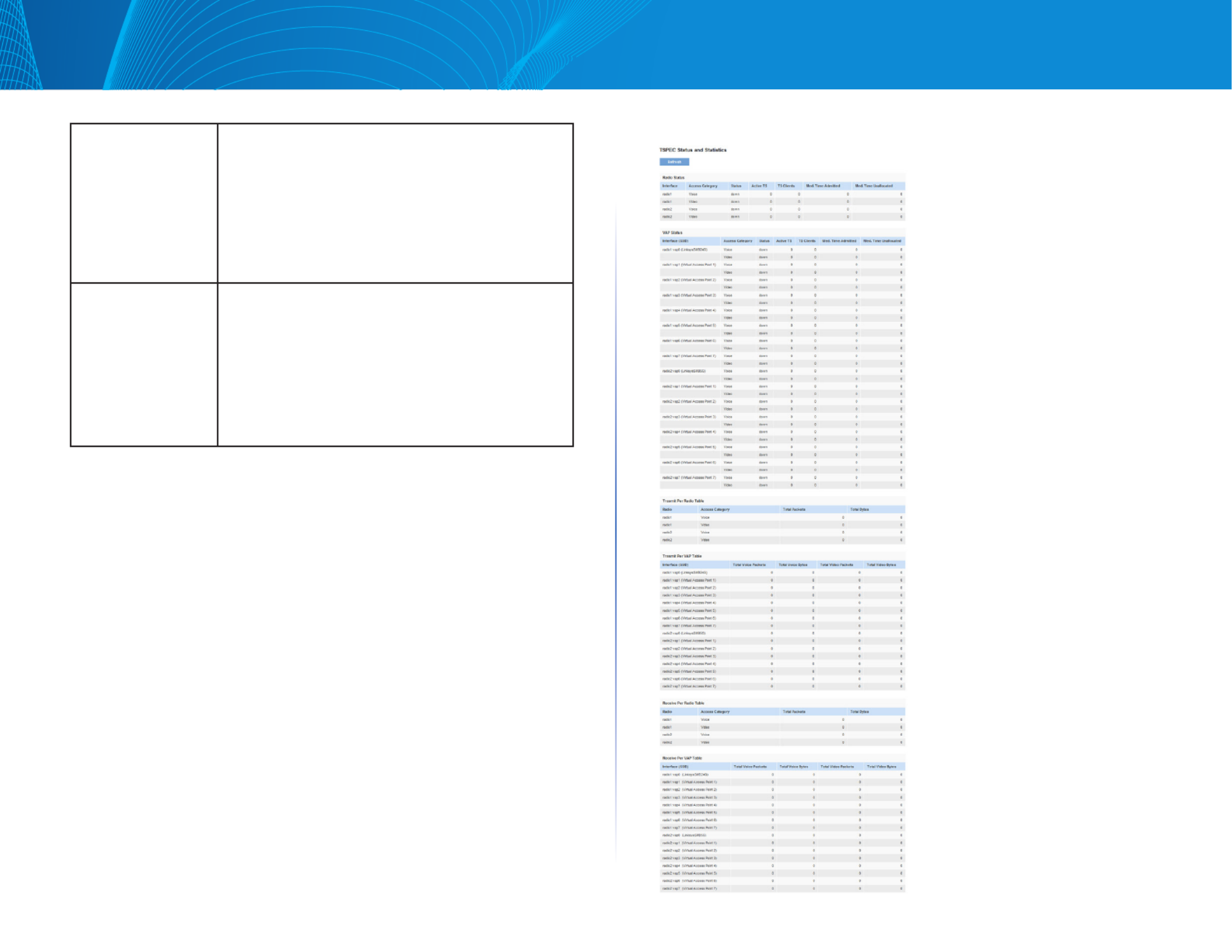
TSPEC Status and Statistics
The TSPEC Status and Statistics page provides:
•Summary information about TSPEC sessions by radio
•Summary information about TSPEC sessions by VAP
•Real-time transmit and receive statistics for the TSPEC VAPs on all radio
interfaces.
All transmit and receive statistics shown are totals since the AP was last started.
If you reboot the AP, these figures indicate transmit and receive totals since the
reboot.
To view TSPEC status and statistics, click the System Status > TSPEC Status
and Statistics tab. The following image has been edited to show some of the
transmit and receive statistics.
Figure 9: TSPEC Status and Statistics

20
Section 3: Configuring the Access PointLAPAC1750PRO Access Point Software User Manual
Device Name Name your AP. This name appears only on the Basic Settings
page and is used to identify the AP to the administrator.
A valid name is 1 to 64 alphanumeric characters, and can
include letters, digits, hyphens and spaces.
System
Contact
Enter the name, e-mail address, or phone number of the
person to contact regarding issues related to the AP.
System
Location
Enter the physical location of the AP, for example
Conference Room A.
Time Settings
The Network Time Protocol (NTP) is an Internet standard protocol that
synchronizes computer clock times on your network. NTP servers transmit
Coordinated Universal Time (UTC, also known as Greenwich Mean Time) to their
client systems. NTP sends periodic time requests to servers, using the returned
time stamp to adjust its clock. The timestamp is used to indicate the date and
time of each event in log messages.
See http://www.ntp.org for more information about NTP.
To configure the address of the NTP server that the AP uses or to set the system
time manually, click the Configuration > Administration > Time Settings tab and
update the fields as described in Table 16.
NOTE:
The fields available to configure depend on whether you choose to set
the system time manually or by using an NTP server.
Figure 14 shows the Time Settings page when the manual option is selected.
Figure 14: Setting the Time Manually
Figure 15 shows the Time Settings page when the Use Network Time Protocol
(NTP) option is selected.
Figure 15: Setting the Time Using an NTP Server

24
Section 3: Configuring the Access PointLAPAC1750PRO Access Point Software User Manual
From Email Address Specify the email address that appears in the From
field of alert messages sent from the AP, for example
AP23@foo.com. The address can be a maximum
of 255 characters and can contain only printable
characters. By default, no address is configured.
Log Duration This duration, in minutes, determines how frequently
the non critical messages are sent to the SMTP
Server. The range is 30-1440 minutes. The default is
30 minutes.
Urgent Message
Severity
Configures the severity level for log messages
that are considered to be urgent. Messages in this
category are sent immediately. The security level you
select and all higher levels are urgent:
• Emergency indicates system is unusable. It is the
highest level of severity.
• Alert indicates action must be taken
immediately.
• Critical indicates critical conditions.
• Error indicates error conditions.
• Warning indicates warning conditions.
• Notice indicates normal but significant
conditions.
• Informational indicates informational messages.
• Debug indicates debug-level messages.
Non Urgent Severity Configures the severity level for log messages that
are considered to be non urgent. Messages in this
category are collected and sent in a digest form at
the time interval specified by the Log Duration field.
The security level you select, and all levels up to but
not including the lowest urgent level, are considered
non-urgent. Messages below the security level you
specify are not sent via email.
See the Urgent Message field description for
information about the security levels.
Mail Server Configuration
Mail Server Address Specify the IP address or hostname of the SMTP
server on the network.
Mail Server Security Specify whether to use SMTP over SSL (TLSv1) or
no security (Open) for authentication with the mail
server. The default is TLSv1.
Mail Server Port Configures the TCP port number for SMTP. The range
is a valid port number from 0 to 65535. The default is
“465”, which is the standard port for SMTP.
Username Specify the username to use when authentication
with the mail server is required. The username is a
64-byte character string with all printable characters.
The default is “admin”.
Password Specify the password associated with the username
configured in the previous field.
Message Configuration
To Address 1 Configure the first email address to which alert
messages are sent. The address must be a valid email
address. By default, no address is configured.
To Address 2 Optionally, configure the second email address to
which alert messages are sent. The address must
be a valid email address. By default, no address is
configured.
To Address 3 Optionally, configure the third email address to
which alert messages are sent. The address must
be a valid email address. By default, no address is
configured.
Email Subject Specify the text to be displayed in the subject of the
email alert message. The subject can contain up to
255 alphanumeric characters. The default is “Log
message from AP”.

29
Section 3: Configuring the Access PointLAPAC1750PRO Access Point Software User Manual
LAN
This section describes how to manage the access point and contains the
following subsections:
• VLAN and IPv4 Address
• IPv6 Address
• IPv6 Tunnel
The configuration pages for the features in this section are located under the
Manage heading on the Administration Web UI.
VLAN and IPv4 Address
The default wired interface settings, which include DHCP and VLAN information,
might not work for all networks.
By default, the DHCP client on the access point automatically broadcasts
requests for network information. If you want to use a static IP address, you
must disable the DHCP client and manually configure the IP address and other
network information.
The management VLAN is VLAN 1 by default. This VLAN is also the default
untagged VLAN. If you already have a management VLAN configured on
your network with a different VLAN ID, you must change the VLAN ID of the
management VLAN on the AP.
To configure the LAN settings, click the Configuration > LAN > VLAN and IPv4
Address tab.
Figure 22: VLAN and IPv4 Address
The following table describes the fields to view or configure on the VLAN and
IPv4 Address page.
Table 25: VLAN and IPv4 Address
Field Description
MAC Address Shows the MAC address for the LAN interface for the
Ethernet port on this AP. This is a read-only field that you
cannot change.
Management
VLAN ID
The management VLAN is the VLAN associated with the IP
address you use to access the AP. The default management
VLAN ID is “1.”
Provide a number between 1 and 4094 for the management
VLAN ID.

34
Section 3: Configuring the Access PointLAPAC1750PRO Access Point Software User Manual
Radio
Radio settings directly control the behavior of the radio devices in the AP, and
determine how and what type of electromagnetic waves the AP emits.
Different settings display depending on the mode you select. All settings are
described in Table 28.
Figure 25: Radio Settings
Table 28: Radio Settings
Field Description
Radio Select Radio 1 or Radio 2 to specify which radio to
configure. Radio 1 stands for 2.4GHz radio, and Radio
2 stands for 5GHz radio. The rest of the settings on this
tab apply to the radio you select in this field. Be sure to
configure settings for both radios.
Status (On/Off) Specify whether you want the radio on or off by selecting
On or Off.
If you turn off a radio, the AP sends disassociation frames
to all the wireless clients it is currently supporting so that
the radio can be gracefully shutdown and the clients can
start the association process with other available APs.
MAC Address Indicates the Media Access Control (MAC) addresses for
the interface.
This page shows the MAC addresses for Radio interface.
A MAC address is a permanent, unique hardware address
for any device that represents an interface to the network.
The MAC address is assigned by the manufacturer. You
cannot change the MAC address. It is provided here
for informational purposes as a unique identifier for an
interface.

38
Section 3: Configuring the Access PointLAPAC1750PRO Access Point Software User Manual
Fragmentation
Threshold
Specify a number between 256 and 2,346 to set the
frame size threshold in bytes.
The fragmentation threshold is a way of limiting the
size of packets (frames) transmitted over the network. If
a packet exceeds the fragmentation threshold you set,
the fragmentation function is activated and the packet is
sent as multiple 802.11 frames.
If the packet being transmitted is equal to or less than
the threshold, fragmentation is not used.
Setting the threshold to the largest value (2,346 bytes)
effectively disables fragmentation. Fragmentation plays
no role when Aggregation is enabled.
Fragmentation involves more overhead both because
of the extra work of dividing up and reassembling of
frames it requires, and because it increases message
traffic on the network. However, fragmentation can help
improve network performance and reliability if properly
configured.
Sending smaller frames (by using lower fragmentation
threshold) might help with some interference problems;
for example, with microwave ovens.
By default, fragmentation is off. We recommend not using
fragmentation unless you suspect radio interference. The
additional headers applied to each fragment increase
the overhead on the network and can greatly reduce
throughput.
RTS Threshold Specify a Request to Send (RTS) Threshold value between
0 and 2347.
The RTS threshold indicates the number of octets in
an MPDU, below which an RTS/CTS handshake is not
performed.
Changing the RTS threshold can help control traffic flow
through the AP, especially one with a lot of clients. If you
specify a low threshold value, RTS packets will be sent
more frequently. This will consume more bandwidth
and reduce the throughput of the packet. On the other
hand, sending more RTS packets can help the network
recover from interference or collisions which might
occur on a busy network, or on a network experiencing
electromagnetic interference.
Maximum
Stations
Specify the maximum number of stations allowed to
access this AP at any one time.
You can enter a value between 0 and 200.
Transmit Power Enter a percentage value for the transmit power level for
this AP.
The default value, which is 100%, can be more cost-
efficient than a lower percentage since it gives the AP a
maximum broadcast range and reduces the number of
APs needed.
To increase capacity of the network, place APs closer
together and reduce the value of the transmit power.
This helps reduce overlap and interference among APs. A
lower transmit power setting can also keep your network
more secure because weaker wireless signals are less
likely to propagate outside of the physical location of
your network.
Fixed Multicast
Rate
Select the multicast traffic transmission rate you want
the AP to support.

57
Section 3: Configuring the Access PointLAPAC1750PRO Access Point Software User Manual
WPA/PSK on WDS Links
The following table describes the additional fields that appear when you select
WPA/PSK as the encryption type.
NOTE:
In order to configure WPA-PSK on any WDS link, VAP0 of the selected
radio must be configured for WPA-PSK or WPA-Enterprise.
Table 40: WPA/PSK on WDS Links
Field Description
Encryption WPA (PSK).
SSID Enter an appropriate name for the new WDS link you have
created. This SSID should be different from the other SSIDs
used by this AP. However, it is important that the same SSID is
also entered at the other end of the WDS link. If this SSID is not
the same for both APs on the WDS link, they will not be able to
communicate and exchange data.
The SSID can be any alphanumeric combination.
Key Enter a unique shared key for the WDS bridge. This unique
shared key must also be entered for the AP at the other end of
the WDS link. If this key is not the same for both APs, they will
not be able to communicate and exchange data.
The WPA-PSK key is a string of at least 8 characters to a
maximum of 63 characters. Acceptable characters include
upper and lower case alphabetic letters, the numeric digits,
and special symbols such as @ and #.
NOTE:
After you configure the WDS settings, you must click Save to apply the
changes and to save the settings. Changing some settings might cause
the AP to stop and restart system processes. If this happens, wireless
clients will temporarily lose connectivity. We recommend that you
change AP settings when WLAN traffic is low.
NOTE:
Partner WDS AP in the remote network retains its management IP
address acquired from a DHCP server connected to the WDS AP in the
main network even if the WDS link is broken. The IP address is released
when the WDS interface is brought administratively down.
Workgroup Bridges
The Workgroup Bridge feature enables the AP to extend the accessibility of a
remote network. In Workgroup Bridge mode, the access point acts as a wireless
station (STA) on the wireless LAN. It can bridge traffic between a remote wired
network or associated wireless clients and the wireless LAN that is connected
using the Workgroup Bridge mode.
The Workgroup Bridge feature enables support for STA-mode and AP-mode
operation simultaneously. The access point can operate in one BSS as an STA
device while operating on another BSS as an access point. When Workgroup
Bridge mode is enabled, then the access point supports only one BSS for
wireless clients that associate with it, and another BSS to which the access
point associates as a wireless client.
It is recommended that Workgroup Bridge mode be used only when the WDS
bridge feature cannot be operational with a peer Access Point. WDS is a better
solution and is preferred over the Workgroup Bridge solution. The Workgroup
Bridge feature should be used only when connecting to AP devices from a
different manufacturer. When the Workgroup Bridge feature is enabled, the
VAP configurations are not applied; only the Workgroup Bridge configuration
is applied.
NOTE:
The WDS feature does not work when the Workgroup Bridge mode is
enabled on the access point.
In Workgroup Bridge mode, the BSS managed by the access point while
operating in access point mode is referred to as the access point interface, and
associated STAs as downstream STAs. The BSS managed by the other access
point (that is, the one to which the access point associates as an STA) is referred
to as the infrastructure client interface, and the other access point is referred
as the upstream AP.

59
Section 3: Configuring the Access PointLAPAC1750PRO Access Point Software User Manual
Table 41: Workgroup Bridge
Field Description
Workgroup
Bridge Mode
Set the administrative mode of the Workgroup Bridge
feature.
Radio Select the radio on which to configure Workgroup Bridge
mode.
Infrastructure Client Interface
VLAN ID The VLAN associated with the BSS.
SSID The SSID of the Basic Service Set (BSS). The BSS includes
upstream access point and all of its connected clients
(STAs).
Security The type of security to use for authenticating as a client
station on the upstream access point. Choices are:
•None
•Static WEP
•WPA Personal
•WPA Enterprise
Connection
Status
The Infrastructure Client Interface will be associated to the
upstream access point with the configured credentials.
The access point may obtain its IP address from a DHCP
server on the upstream link. Alternatively, you can assign
a static IP address. The Connection Status field indicates
whether the WAP is connected to the upstream access
point. Click Refresh to view the latest connection status.
Access Point Interface
Status Status is indicated as Up (Enable) or Down (disable). If the
downstream interface is down, wireless clients cannot
connect to the access point.
VLAN ID The VLAN ID on the local AP interface. This VLAN ID should
be the same VLAN ID as advertised on the Infrastructure
Client Interface.
SSID Specify the SSID to broadcast to downstream clients.
Broadcast
SSID
Select this option if you want the downstream SSID to be
broadcast to wireless clients.
Security Select the type of security downstream clients will use to
authenticate with the access point. Choices are:
•None
•WPA Personal
•WPA Enterprise
MAC
Authentication
Type
Select one of the following options for MAC authentication:
•Disabled—The set of clients in the APs BSS that can
access the upstream network is not restricted to the
clients specified in a MAC address list.
•Local—The set of clients in the AP’s BSS that can
access the upstream network is restricted to the
clients specified in a locally defined MAC address list.
•RADIUS—The set of clients in the AP’s BSS that can
access the upstream network is restricted to the
clients specified in a MAC address list on a RADIUS
server.
If you select Local or RADIUS, see “MAC Filter” for
instructions on creating the MAC filter list.

61
Section 3: Configuring the Access PointLAPAC1750PRO Access Point Software User Manual
WAP EDCA Parameters
Queue Queues are defined for different types of data
transmitted from AP-to-station:
•Data 0 (Voice) — High priority queue, minimum
delay. Time-sensitive data such as VoIP and
streaming media are automatically sent to this
queue.
•Data 1(Video) — High priority queue, minimum
delay. Time-sensitive video data is automatically
sent to this queue.
•Data 2 (best effort) — Medium priority queue,
medium throughput and delay. Most traditional
IP data is sent to this queue.
•Data 3 (Background) — Lowest priority queue,
high throughput. Bulk data that requires
maximum throughput and is not time-sensitive
is sent to this queue (FTP data, for example).
AIFS (Inter-Frame
Space)
Arbitration Inter-Frame Spacing (AIFS) specifies a wait
time for data frames. The wait time is measured in
slots. Valid values for AIFS are 1 through 255.
cwMin(M inimum
Contention
Window)
This parameter is input to the algorithm that
determines the initial random backoff wait time
(window) for retry of a transmission.
The value specified for Minimum Contention Window is
the upper limit (in milliseconds) of a range from which
the initial random backoff wait time is determined.
The first random number generated will be a number
between 0 and the number specified here.
If the first random backoff wait time expires before
the data frame is sent, a retry counter is incremented
and the random backoff value (window) is doubled.
Doubling will continue until the size of the random
backoff value reaches the number defined in the
Maximum Contention Window.
Valid values for cwMin are 1, 3, 7, 15, 31, 63, 127, 255,
511, or 1023. The value for cwMin must be lower than
the value for cwMax.
cwMax
(Maximum
Contention
Window)
The value specified for the Maximum Contention
Window is the upper limit (in milliseconds) for the
doubling of the random backoff value. This doubling
continues until either the data frame is sent or the
Maximum Contention Window size is reached.
Once the Maximum Contention Window size is
reached, retries will continue until a maximum
number of retries allowed is reached.
Valid values for cwMax are 1, 3, 7, 15, 31, 63, 127, 255,
511, or 1023. The value for cwMax must be higher
than the value for cwMin.

65
Section 3: Configuring the Access PointLAPAC1750PRO Access Point Software User Manual
802.1X Supplicant
802.1X Supplicant settings allow the access point to gain access to a secured
wired network.
Use these settings to enable the access point as an 802.1X supplicant (client)
on the wired network. An MD5 user name and password can be configured to
allow the access point to authenticate via 802.1X.
On networks that use IEEE 802.1X, port-based network access control, a
supplicant cannot gain access to the network until the 802.1X authenticator
grants access. If your network uses 802.1X, you must configure 802.1X
authentication information that the AP can supply to the authenticator.
To configure the access point 802.1X supplicant user name and password by
using the Web interface, click the Configuration > Security > 802.1X Supplicant
tab and configure the fields shown in Table 44.
Figure 36: 802.1X Supplicant
Table 44: 802.1X Supplicant Authentication
Field Description
Supplicant Configuration
802.1X
Supplicant
Click Enabled to enable the Administrative status of the
802.1X Supplicant.
Click Disabled to disable the Administrative status of the
802.1X Supplicant.
EAP
Method
Select the algorithm to be used for encrypting authentication
user names and passwords. The options are as follows:
• MD5—A hash function defined in RFC 3748 that provides
basic security.
• PEAP—Protected Extensible Authentication Protocol,
which provides a higher level of security than MD5 by
encapsulating it within a TLS tunnel.
• TLS—Transport Layer Security, as defined in RFC 5216, an
open standard that provides a high level of security.
Username Enter the MD5 user name for the AP to use when responding
to requests from an 802.1X authenticator. The user name can
be up to 64 characters. ASCII printable characters are allowed,
which includes upper and lower case alphabetic letters, the
numeric digits, and special symbols such as @ and #.
Password Enter the MD5 password for the AP to use when responding to
requests from an 802.1X authenticator. The password can be
up1 to 64 characters. ASCII printable characters are allowed,
which includes upper and lower case letters, numbers, and
special symbols such as @ and #.
Certificate File Status
Certificate
File Present
Indicates if the HTTP SSL Certificate file is present. Range is yes
or no. The default is no.
Certificate
Expiration
Date
Indicates when the HTTP SSL Certificate file will expire. The
range is a valid date. If no certificate file exists on the AP, the
field displays Not Present.
66
Section 3: Configuring the Access PointLAPAC1750PRO Access Point Software User Manual
Certificate File Upload
Upload
Method
Select the method to use for uploading a certificate file to the
AP, which is either HTTP/HTTPS (upload by Web browser) or
TFTP (upload by TFTP server).
Filename Specify the path and filename of the certificate file:
• For HTTP uploads, click Browse to find the location where
the certificate file is stored. Select the file to upload to the
access point. Click Upload to initiate the file transfer.
• For TFTP uploads, enter the filename, including the path,
of the certificate to upload to the access point.
Server
IP (TFTP
Upload
Only)
The IPv4 or IPv6 address of the TFTP server where the file is
located. The default is 0.0.0.0. After you specify the filename
and server IP, click Upload to initiate the file transfer.
NOTE:
After you configure the settings on the 802.1X Supplicant page, you must
click Save to apply the changes. Changing some settings might cause the
AP to stop and restart system processes. If this happens, wireless clients
will temporarily lose connectivity. We recommend that you change AP
settings when WLAN traffic is low.
QoS and Access Control
This section describes how to configure QoS settings that affect traffic from the
wireless clients to the AP. By using the access point Client QoS features, you can
limit bandwidth and apply ACLs and DiffServ policies to the wireless interface.
This section describes the following features:
• Global Settings.
• ACL
• Class Map
• Policy Map
• Client QoS Status

69
Section 3: Configuring the Access PointLAPAC1750PRO Access Point Software User Manual
Figure 38: ACL Table 46: ACL Configuration
Field Description
ACL
ACL Name Enter a name to identify the ACL. The name can
contain from 1–31 alphanumeric characters and the
following special characters: hyphen, underscore,
backslash and colon. Spaces are not allowed.
ACL Type Select the type of ACL to configure:
• IPv4
• IPv6
• MAC
IPv4 and IPv6 ACLs control access to network
resources based on Layer 3 and Layer 4 criteria. MAC
ACLs control access based on Layer 2 criteria.
ACL RULE SETTING
ACL Name and Type Select the ACL to configure with the new rule. The
list contains all ACLs added in the ACL Configuration
section.
Rule To configure a new rule to add to the selected ACL,
select New Rule. To add an existing rule to an ACL or
to modify a rule, select the rule number.
When an ACL has multiple rules, the rules are applied
to the packet or frame in the order in which you add
them to the ACL. There is an implicit deny all rule as
the final rule.

70
Section 3: Configuring the Access PointLAPAC1750PRO Access Point Software User Manual
Action Specifies whether the ACL rule permits or denies an
action.
•When you select Permit, the rule allows all traffic
that meets the rule criteria to enter or exit the
AP (depending on the ACL direction you select).
Traffic that does not meet the criteria is dropped.
•When you select Deny, the rule blocks all traffic
that meets the rule criteria from entering or
exiting the AP (depending on the ACL direction
you select). Traffic that does not meet the criteria
is forwarded unless this rule is the final rule.
Because there is an implicit deny all rule at the
end of every ACL, traffic that is not explicitly
permitted is dropped.
Match Every Indicates that the rule, which either has a permit or
deny action, will match the frame or packet regardless
of its contents.
If you select this field, you cannot configure any
additional match criteria. The Match Every option is
selected by default for a new rule. You must clear the
option to configure other match fields.
IPv4 ACL
Protocol Select the Protocol field to use a Layer 3 or Layer 4
protocol match condition based on the value of the
IP Protocol field in IPv4 packets or the Next Header
field of IPv6 packets.
Once you select the field, choose the protocol to
match by keyword or enter a protocol ID.
Select From List
Select one of the following protocols from the list:
•IP
•ICMP
•IGMP
•TCP
•UDP
Match to Value
To match a protocol that is not listed by name, enter
the protocol ID.
The protocol ID is a standard value assigned by the
IANA. The range is a number from 0–255.
Source IP Address Select this field to require a packet’s source IP address
to match the address listed here. Enter an IP address
in the appropriate field to apply this criterion.
Wild Card Mask Specifies the source/destination IP address wildcard
mask.
The wild card mask determines which bits are used
and which bits are ignored. A wild card mask of
255.255.255.255 indicates that no bit is important.
A wildcard of 0.0.0.0 indicates that all of the bits
are important. This field is required when Source IP
Address is checked.
A wild card mask is in essence the inverse of a subnet
mask. For example, to match the criteria to a single
host address, use a wildcard mask of 0.0.0.0. To
match the criteria to a 24-bit subnet (for example,
192.168.10.0/24), use a wild card mask of 0.0.0.255.

72
Section 3: Configuring the Access PointLAPAC1750PRO Access Point Software User Manual
IP TOS Mask Enter an IP TOS mask value to identify the bit positions
in the TOS Bits value that are used for comparison
against the IP TOS field in a packet.
The TOS Mask value is a two-digit hexadecimal
number from 00 to ff, representing an inverted (i.e.
wildcard) mask. The zero-valued bits in the TOS Mask
denote the bit positions in the TOS Bits value that
are used for comparison against the IP TOS field of
a packet. For example, to check for an IP TOS value
having bits 7 and 5 set and bit 1 clear, where bit 7 is
most significant, use a TOS Bits value of a0 and a TOS
Mask of 00. This is an optional configuration.
IPv6 ACL
Protocol Select the Protocol field to use a Layer 3 or Layer 4
protocol match condition based on the value of the
IP Protocol field in IPv4 packets or the Next Header
field of IPv6 packets.
Once you select the field, choose the protocol to
match by keyword or protocol ID.
Source IPv6
Address
Select this field to require a packet’s source IPv6
address to match the address listed here. Enter an
IPv6 address in the appropriate field to apply this
criterion.
Source IPv6 Prefix
Len
Enter the prefix length of the source IPv6 address.
Source Port Select this option to include a source port in the
match condition for the rule. The source port is
identified in the datagram header.
Once you select the option, choose the port name or
enter the port number.
Destination IPv6
Address
Select this field to require a packet’s destination IPv6
address to match the address listed here. Enter an
IPv6 address in the appropriate field to apply this
criterion.
Destination IPv6
Prefix Len
Enter the prefix length of the destination IPv6 address.
Source Port Range Enter the port range to match to the source port
identified in the datagram header. The port range is
0–65535 and includes three different types of ports:
• 0–1023: Well Known Ports
• 1024–49151: Registered Ports
• 49152–65535: Dynamic and/or Private Ports
To specify a single port, use the same value for the
start and end range.
Destination Port Select this option to include a destination port in the
match condition for the rule. The destination port is
identified in the datagram header.
Once you select the option, choose the port name or
enter the port number.
IPv6 Flow Label Flow label is 20-bit number that is unique to an IPv6
packet. It is used by end stations to signify quality-of-
service handling in routers (range 0 to 1048575).
Specyfikacje produktu
| Marka: | Linksys |
| Kategoria: | Punkt dostępu |
| Model: | LAPAC1750PRO-EU |
Potrzebujesz pomocy?
Jeśli potrzebujesz pomocy z Linksys LAPAC1750PRO-EU, zadaj pytanie poniżej, a inni użytkownicy Ci odpowiedzą
Instrukcje Punkt dostępu Linksys

2 Września 2024
31 Sierpnia 2024
30 Sierpnia 2024
25 Sierpnia 2024
22 Sierpnia 2024
21 Sierpnia 2024
20 Sierpnia 2024
20 Sierpnia 2024
19 Sierpnia 2024
18 Sierpnia 2024
Instrukcje Punkt dostępu
- Punkt dostępu Tenda
- Punkt dostępu Huawei
- Punkt dostępu TP-Link
- Punkt dostępu Bosch
- Punkt dostępu StarTech.com
- Punkt dostępu Asus
- Punkt dostępu TRENDnet
- Punkt dostępu D-Link
- Punkt dostępu HP
- Punkt dostępu Honeywell
- Punkt dostępu Mikrotik
- Punkt dostępu Cisco
- Punkt dostępu Moxa
- Punkt dostępu Lindy
- Punkt dostępu Zebra
- Punkt dostępu ZyXEL
- Punkt dostępu V7
- Punkt dostępu Dell
- Punkt dostępu Digitus
- Punkt dostępu Vimar
- Punkt dostępu Dahua Technology
- Punkt dostępu Renkforce
- Punkt dostępu Netgear
- Punkt dostępu AVM
- Punkt dostępu Homematic IP
- Punkt dostępu Totolink
- Punkt dostępu Black Box
- Punkt dostępu Lancom
- Punkt dostępu Intellinet
- Punkt dostępu Devolo
- Punkt dostępu Kingston
- Punkt dostępu Speco Technologies
- Punkt dostępu Mercusys
- Punkt dostępu Draytek
- Punkt dostępu Edimax
- Punkt dostępu AirLive
- Punkt dostępu EnGenius
- Punkt dostępu Planet
- Punkt dostępu LevelOne
- Punkt dostępu Ubiquiti Networks
- Punkt dostępu Juniper
- Punkt dostępu Cudy
- Punkt dostępu Netis
- Punkt dostępu Allnet
- Punkt dostępu Media-Tech
- Punkt dostępu EQ-3
- Punkt dostępu Grandstream
- Punkt dostępu Allied Telesis
- Punkt dostępu Eminent
- Punkt dostępu Sitecom
- Punkt dostępu Fortinet
- Punkt dostępu Techly
- Punkt dostępu Steren
- Punkt dostępu Buffalo
- Punkt dostępu Macally
- Punkt dostępu Aruba
- Punkt dostępu Interlogix
- Punkt dostępu EQ3
- Punkt dostępu Hawking Technologies
- Punkt dostępu INCA
- Punkt dostępu Moog
- Punkt dostępu LigoWave
- Punkt dostępu Advantech
- Punkt dostępu Hercules
- Punkt dostępu SMC
- Punkt dostępu CradlePoint
- Punkt dostępu Silex
- Punkt dostępu Aerohive
- Punkt dostępu Bountiful
- Punkt dostępu WatchGuard
- Punkt dostępu NUVO
- Punkt dostępu IP-COM
- Punkt dostępu Syscom
- Punkt dostępu Meru
- Punkt dostępu Amped Wireless
- Punkt dostępu Cambium Networks
- Punkt dostępu 3Com
- Punkt dostępu Ruckus Wireless
- Punkt dostępu Bintec-elmeg
- Punkt dostępu Mach Power
- Punkt dostępu Brocade
- Punkt dostępu Insteon
- Punkt dostępu Comtrend
- Punkt dostępu Premiertek
- Punkt dostępu Extreme Networks
- Punkt dostępu Atlantis Land
- Punkt dostępu Mojo
- Punkt dostępu FlyingVoice
- Punkt dostępu Luxul
- Punkt dostępu Peplink
Najnowsze instrukcje dla Punkt dostępu
9 Kwietnia 2025
9 Kwietnia 2025
5 Kwietnia 2025

2 Kwietnia 2025
20 Marca 2025
28 Lutego 2025
27 Stycznia 2025
26 Stycznia 2025

15 Stycznia 2025
14 Stycznia 2025