Instrukcja obsługi Hikvision DS-KM9503
Przeczytaj poniżej 📖 instrukcję obsługi w języku polskim dla Hikvision DS-KM9503 (54 stron) w kategorii Interkom. Ta instrukcja była pomocna dla 7 osób i została oceniona przez 2 użytkowników na średnio 4.5 gwiazdek
Strona 1/54

Video Intercom Main Staon
Conguraon Guide

Legal Informaon
©2020 Hangzhou Hikvision Digital Technology Co., Ltd. All rights reserved.
About this Manual
The Manual includes for using and managing the Product.instrucons
Pictures, charts, images and all other informaon hereinaer are for
descripon explanaon and only. The contained in the Manualinformaon
is subject to change, without noce, rmware due to updates or other
reasons. Please the latest version of this Manual at the Hikvisionnd
website ( hps://www.hikvision.com/ ).
Please use this Manual with the guidance and assistance of professionals
trained in supporng the Product.
Trademarks
and other Hikvision's trademarks and logos are the
properes of Hikvision in various jurisdicons.
Other trademarks and logos are the menoned properes of their
respecve owners.
Disclaimer
TO THE MAXIMUM EXTENT PERMITTED BY APPLICABLE LAW, THIS MANUAL
AND THE PRODUCT DESCRIBED, WITH ITS HARDWARE, SOFTWARE AND
FIRMWARE, ARE PROVIDED “AS IS” AND “WITH ALL FAULTS AND ERRORS”.
HIKVISION MAKES NO WARRANTIES, EXPRESS OR IMPLIED, INCLUDING
WITHOUT LIMITATION, MERCHANTABILITY, SATISFACTORY QUALITY, OR
FITNESS FOR A PARTICULAR PURPOSE. THE USE OF THE PRODUCT BY YOU IS
AT YOUR OWN RISK. IN NO EVENT WILL HIKVISION BE LIABLE TO YOU FOR
ANY SPECIAL, CONSEQUENTIAL, INCIDENTAL, OR INDIRECT DAMAGES,
INCLUDING, AMONG OTHERS, DAMAGES FOR LOSS OF BUSINESS PROFITS,
BUSINESS INTERRUPTION, OR LOSS OF DATA, CORRUPTION OF SYSTEMS, OR
LOSS OF DOCUMENTATION, WHETHER BASED ON BREACH OF CONTRACT,
TORT (INCLUDING NEGLIGENCE), PRODUCT LIABILITY, OR OTHERWISE, IN
Video Intercom Main Staon Conguraon Guide
i

CONNECTION WITH THE USE OF THE PRODUCT, EVEN IF HIKVISION HAS
BEEN ADVISED OF THE POSSIBILITY OF SUCH DAMAGES OR LOSS.
YOU ACKNOWLEDGE THAT THE NATURE OF INTERNET PROVIDES FOR
INHERENT SECURITY RISKS, AND HIKVISION SHALL NOT TAKE ANY
RESPONSIBILITIES FOR ABNORMAL OPERATION, PRIVACY LEAKAGE OR
OTHER DAMAGES RESULTING FROM CYBER-ATTACK, HACKER ATTACK, VIRUS
INSPECTION, OR OTHER INTERNET SECURITY RISKS; HOWEVER, HIKVISION
WILL PROVIDE TIMELY TECHNICAL SUPPORT IF REQUIRED.
YOU AGREE TO USE THIS PRODUCT IN COMPLIANCE WITH ALL APPLICABLE
LAWS, AND YOU ARE SOLELY RESPONSIBLE FOR ENSURING THAT YOUR USE
CONFORMS TO THE APPLICABLE LAW. ESPECIALLY, YOU ARE RESPONSIBLE,
FOR USING THIS PRODUCT IN A MANNER THAT DOES NOT INFRINGE ON THE
RIGHTS OF THIRD PARTIES, INCLUDING WITHOUT LIMITATION, RIGHTS OF
PUBLICITY, INTELLECTUAL PROPERTY RIGHTS, OR DATA PROTECTION AND
OTHER PRIVACY RIGHTS. YOU SHALL NOT USE THIS PRODUCT FOR ANY
PROHIBITED END-USES, INCLUDING THE DEVELOPMENT OR PRODUCTION
OF WEAPONS OF MASS DESTRUCTION, THE DEVELOPMENT OR
PRODUCTION OF CHEMICAL OR BIOLOGICAL WEAPONS, ANY ACTIVITIES IN
THE CONTEXT RELATED TO ANY NUCLEAR EXPLOSIVE OR UNSAFE NUCLEAR
FUEL-CYCLE, OR IN SUPPORT OF HUMAN RIGHTS ABUSES.
IN THE EVENT OF ANY CONFLICTS BETWEEN THIS MANUAL AND THE
APPLICABLE LAW, THE LATER PREVAILS.
Data Protecon
During the use of device, personal data will be collected, stored and
processed. To protect data, the development of Hikvision devices
incorporates privacy by design principles. For example, for device with facial
recognion features, biometrics data is stored in your device with
encrypon ngerprint ngerprint method; for device, only template will be
saved, which is impossible to reconstruct a ngerprint image.
As data controller, you are advised to collect, store, process and transfer
data in accordance with the applicable data protecon laws and regulaons,
including without security controls to safeguardlimitaon, conducng
personal data, such as, reasonable implemenng administrave and
physical security controls, conduct periodic reviews and assessments of the
eecveness of your security controls.
Video Intercom Main Staon Conguraon Guide
ii

Symbol Convenons
The symbols that may be found in this document are as follows.dened
Symbol Descripon
Danger Indicates a hazardous which, if not avoided, will orsituaon
could result in death or serious injury.
Cauon Indicates a hazardous which, if notpotenally situaon
avoided, could result in equipment damage, data loss,
performance degradaon, or unexpected results.
Note Provides addional informaon to emphasize or
supplement important points of the main text.
Video Intercom Main Staon Conguraon Guide
iii

Regulatory Informaon
FCC Informaon
Please take that changes or not expressly approvedaenon modicaon
by the party responsible for compliance could void the user's authority to
operate the equipment.
FCC compliance: This equipment has been tested and found to comply with
the limits for a Class B digital device, pursuant to part 15 of the FCC Rules.
These limits are designed to provide reasonable against harmfulprotecon
interference in a residenal installaon. This equipment generates, uses and
can radiate radio frequency energy and, if not installed and used in
accordance with the instrucons, may cause harmful interference to radio
communicaons. However, there is no guarantee that interference will not
occur in a If this equipment does cause harmfulparcular installaon.
interference to radio or television recepon, which can be determined by
turning the equipment and on, the user is encouraged to try to correcto
the interference by one or more of the following measures:
●Reorient or relocate the receiving antenna.
●Increase the separaon between the equipment and receiver.
●Connect the equipment into an outlet on a circuit dierent from that to
which the receiver is connected.
●Consult the dealer or an experienced radio/TV technician for help.
FCC Condions
This device complies with part 15 of the FCC Rules. Operaon is subject to
the following two condions:
●This device may not cause harmful interference.
●This device must accept any interference received, including interference
that may cause undesired operaon.
Video Intercom Main Staon Conguraon Guide
iv

EU Conformity Statement
This product and - if applicable - the supplied accessories too
are marked with "CE" and comply therefore with the applicable
harmonized European standards listed under the EMC Direcve
2014/30/EU, LVD 2014/35/EU, the RoHS Direcve Direcve
2011/65/EU.
2012/19/EU (WEEE Products marked with thisdirecve):
symbol cannot be disposed of as unsorted municipal waste in
the European Union. For proper recycling, return this product
to your local supplier upon the purchase of equivalent new
equipment, or dispose of it at designated points. Forcollecon
more informaon see: hp://www.recyclethis.info .
2006/66/EC This product contains a (baery direcve): baery
that cannot be disposed of as unsorted municipal waste in the
European Union. See the product for documentaon specic
baery informaon. baery The is marked with this symbol,
which may include to indicate cadmium (Cd), leadleering
(Pb), or mercury (Hg). For proper recycling, return the baery
to your supplier or to a designated point. For morecollecon
informaon see: hp://www.recyclethis.info .
Industry Canada ICES-003 Compliance
This device meets the CAN ICES-3 (B)/NMB-3(B) standards requirements.
Video Intercom Main Staon Conguraon Guide
v

4.9 Device Informaon .......................................................................................... 25
5 Remote Conguraon via Web ................................................................ 26
5.1 Acvate Device via Web .................................................................................. 26
5.2 Device Management ....................................................................................... 26
5.3 Parameters ........................................................................................ 28Sengs
5.3.1 System ....................................................................................... 28Sengs
5.3.2 Network .................................................................................... 31Sengs
5.3.3 Video & Audio ........................................................................... 33Sengs
5.3.4 Intercom Sengs .................................................................................... 34
5.3.5 Grab Bag ................................................................................................. 35
5.3.6 The Third-Party APP Sengs .................................................................. 35
6 via Client ............................................................. 37Conguraon Soware
6.1 Edit Network Parameters ................................................................................ 37
6.2 Add Device ...................................................................................................... 37
6.2.1 Add Online Device .................................................................................. 37
6.2.2 Add Device by IP Address ....................................................................... 38
6.2.3 Add Device by IP Segment ...................................................................... 38
6.3 Remote Conguraon ..................................................................................... 39
6.4 Device Management ....................................................................................... 39
6.5 Organizaon Management ............................................................................. 39
6.5.1 Add Organizaon .................................................................................... 39
6.5.2 Modify and Delete Organizaon ............................................................. 40
6.6 Video Intercom .................................................................................. 40Sengs
6.6.1 Receive Call from Door ............................................................... 40Staon
Video Intercom Main Staon Conguraon Guide
vii

6.6.2 Live View via Door ...................................................................... 41Staon
6.6.3 Release ........................................................................................ 41Noce
6.6.4 Search Video Intercom Informaon ....................................................... 42
A. Matrix and Device Command ....................................... 44Communicaon
Video Intercom Main Staon Conguraon Guide
viii

1 Appearance
Front Panel
Figure 1-1 Front Panel
Table 1-1 Descripon
No. No.Descripon Descripon
1 Phone 7 Camera
2 Phone
Indicator(Reserved)
8 Screen
3 Power Indicator 9 Call/Hang Up Buon
4 Alarm Indicator 10 Unlock Buon
5 Indicator 11 Speaker Informaon Buon
6 Microphone
Video Intercom Main Staon Conguraon Guide
1

Note
You can hold the unlock to unlock lock 1, and press the unlockbuon
buon to unlock lock 2.
Top Panel and Rear Panel
Figure 1-2 Top Panel and Rear Panel
Table 1-2 Descripon
No. No.Descripon Descripon
1 Goose Neck Microphone
Port
5 USB Interface
2 SD Card Slot 6 Power Interface
3 Earphone Interface 7 Terminals
4 HDMI 8 Network Interface
Video Intercom Main Staon Conguraon Guide
2

Speaker(Oponal)
Figure 1-3 Speaker
Table 1-3 Descripon
N
o
.
Descripon DescriponNo.
1Speaker 2 Fingerprint Module
Video Intercom Main Staon Conguraon Guide
3

2 Terminal Descripon
Figure 2-1 Terminal Descripon
Table 2-1 Terminal Descripon
Name Interface Descripon
Video Interface HDMI HDMI Signal Output
USB Interface USB 1 USB Interface
Note
USB3 is used to debugging only. It cannot
connect to USB drive.ash
USB 2
USB 3
Power Interface POWER 12 VDC Power Input
Terminal NO1 Alarm Output 1(NO)
NC1 Alarm Output 1(NC)
COM1 Common Interface
NO2 Alarm Output 2(NO)
NC2 Alarm Output 2(NC)
COM2 Common Interface
AIN1 Alarm Input 1
AIN2 Alarm Input 2
485+ RS-485 InterfacesCommunicaon
485-
Video Intercom Main Staon Conguraon Guide
4

Name Interface Descripon
GND Grounding
GND Grounding
Network
Interface
LAN1(PoE) Network Interface (Support PoE)
LAN2 Network Interface (Reserved)
Video Intercom Main Staon Conguraon Guide
5
3 Installaon
●Make sure the device in the package is in good and all the assemblycondion
parts are included.
●The power supply the door staon support is 12 VDC. Please make sure your
power supply matches your door staon.
●Make sure all the related equipment is power-o installaon. during the
●Check the product for the environment.specicaon installaon
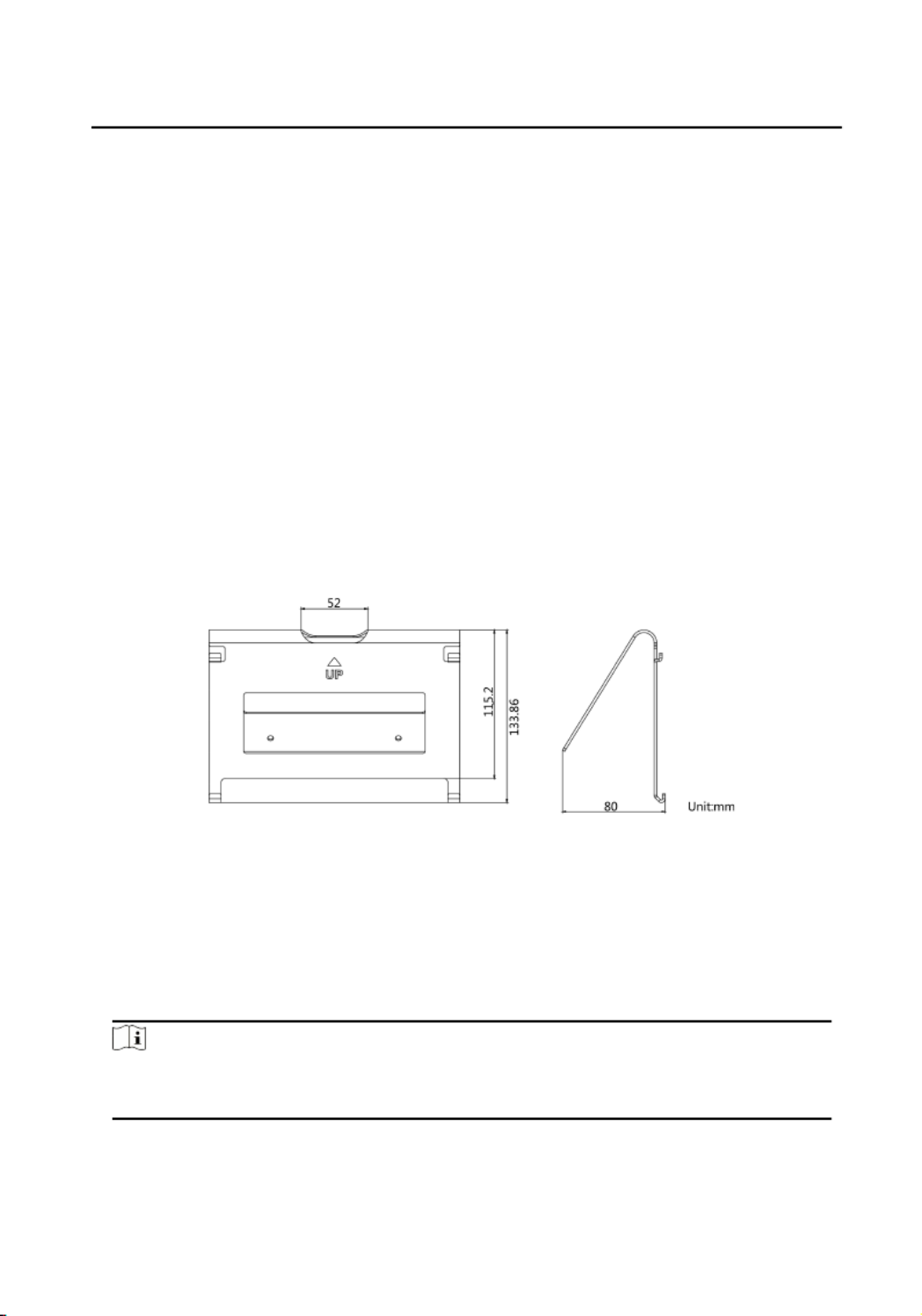
3.1 Table Bracket(Oponal)
The device supports table and wall The dimensions of the tablemounng mounng.
bracket(oponal) is shown as below.
Figure 3-1 Table Bracket
3.2 Accessory Installaon(Oponal)
Before installing the device on the wall or on the table, you should install the
accessories rst.
Note
Ask our technique supports and sales and purchase plate, speaker andmounng
goose neck microphone.
3.2.1 Install Speaker
Video Intercom Main Staon Conguraon Guide
6

Steps
1. Loose 2 screws on the rear panel of the device.
Figure 3-2 Loose the screws
2. Remove the cover from the device and install the speaker to the main staon.
Figure 3-3 Install the Speaker
3. Use 4 screws to secure the speaker to the main staon with the cover.
Video Intercom Main Staon Conguraon Guide
7

Figure 3-4 Secure the Speaker
Note
●The speaker and earphone can not be used at the same If you want to useme.
the earphone, you should remove the speaker.
●When using earphones, the small size of the earphone plug should be selected.
The size of the plug should be smaller than 7 mm.
3.2.2 Install Goose Neck Microphone
If you want to use the goose neck microphone to create two-way audio
communicaon.
Steps
1. Remove the cover of the device on the top panel.
2. Insert the goose neck microphone to the interface.
Video Intercom Main Staon Conguraon Guide
8

Figure 3-5 Install the Goose Neck Microphone
3.3 Wall Mounng
Before You Start
Note
●Tools that you need to prepare for installaon: Drill (6).
●Make sure all the related equipment is power-o installaon. during the
Steps
1. Place the table bracket on the wall. Mark the screw holes' with a marker,posion
and take out the the table bracket. Drill 4 holes according to the marks on the
wall, and insert the expansion sleeves into the screw holes.
2. Secure the table bracket on the wall with 4 screws.
3. Hook the device to the table bracket ghtly inserng by the hooks into the slots
on the rear panel of the device,during which the lock catch will be locked
automacally.
Video Intercom Main Staon Conguraon Guide
9

Figure 3-6 Wall Mounng
3.4 Table Mounng
Steps
1. Wiring the device and smooth the cables across the cable hole.
Figure 3-7 Smooth the Cable
2. Adjust the table bracket to the right angle and put the device on the right
posion.
Figure 3-8 Adjust the Table Bracket
Note
Recommend the use of the table bracket: the maximum opening angle used.
Video Intercom Main Staon Conguraon Guide
10
Note
Default admin password is the password.acvaon
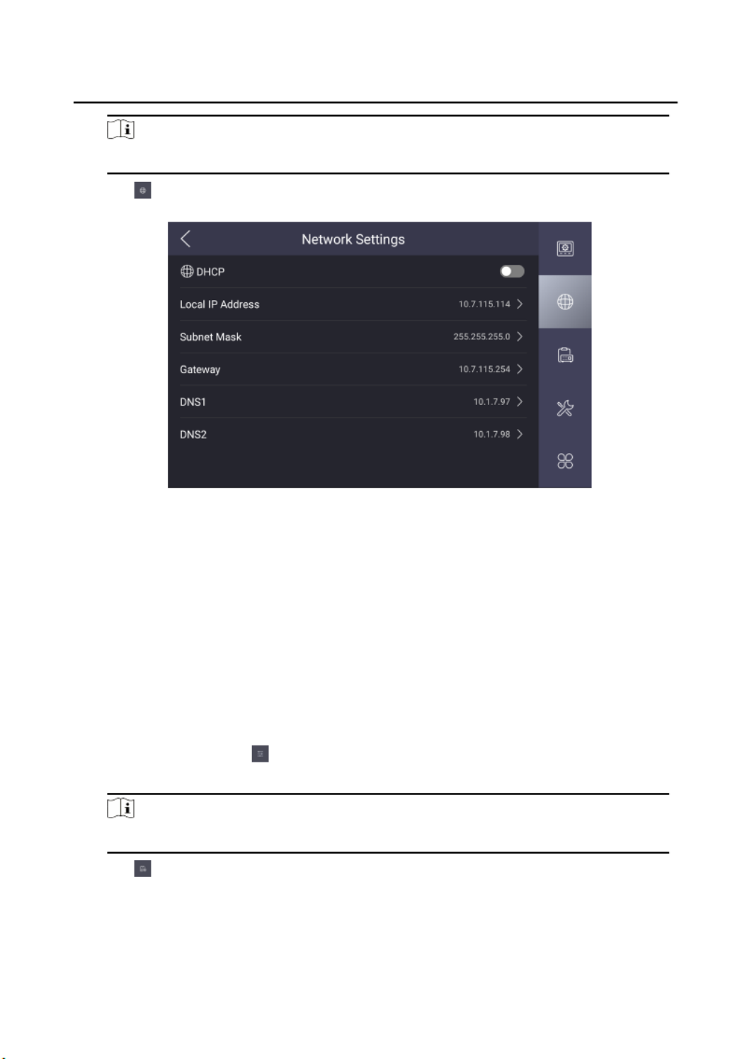
2. Tap to enter the network parameters page.sengs
Figure 4-1 Network Sengs
3. Edit the local network parameters.
-Set the , Local IP Address Subnet Mask Gateway, and DNS address manually.
-Enable , then the device can search and get an IP address DHCP automacally.
4.2.2 Linked Device Management
Linked network parameters refers to the network parameters of device (like indoor
staon, staon, door doorphone, etc.), to whick the main staon is linked.
Steps
1. Tap , and enter the admin password to enterConguraon → → Conguraon
the page.sengs
Note
Default admin password is the password.acvaon
2. Tap to enter the device management page.
Video Intercom Main Staon Conguraon Guide
12
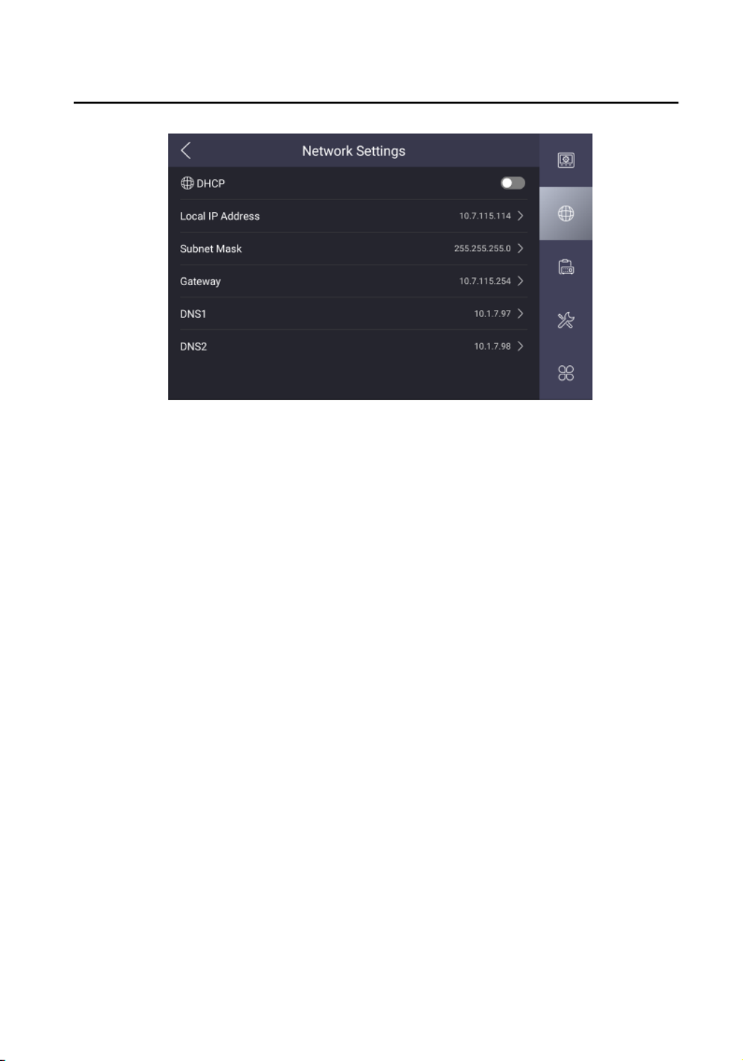
Figure 4-2 Device Management
3. Tap .INTERCOM
4. Tap Add Organizaon to create video intercom system.
Example
If the device is located in Phase 1 Building 1 Unit 1, you should tap Add
Organizaon and create Phase 1 Building 1 Unit 1. First, tap Add Organizaon and
enter the Phase 1 to add rst level. Second, select the Phase 1 and tap Add
Organizaon to add the Building 1 as the sub level. Repeat the steps above to add
the last level.
5. Tap to link the device.+
Video Intercom Main Staon Conguraon Guide
13

Figure 4-3 Add Linked Device
6. Device TypeSelect the as indoor staon, staon, staon door main or doorphone.
7. Serial No. SIP Account SIP Password Password Device IPSet the , , , Acvaon ,
Address Subnet Mask and .
8. Tap to add.√
4.2.3 Set Device No.
Main staon No. can be dialed by other devices to call the main staon in an
intercom system. The main staon No., is composed of the phase No. and No.
Steps
1. Tap , and enter the admin password to enterConguraon → → Conguraon
the page.sengs
Note
Default admin password is the acvaon password.
2. Tap to enter the Main page.Staon Sengs
Video Intercom Main Staon Conguraon Guide
14

Figure 4-4 Device Sengs
3. Phase No. No.Edit the and of the device.
4. Set the SIP server parameters. (Including SIP password, SIP server IP address, SIP
server port and VoIP accout sengs.)
5. Live View TimeSet the .
4.2.4 Add Camera
The main staon can monitor via the camera. You should add cameras rst.
Steps
1. Tap , and enter the admin password to enterConguraon → → Conguraon
the page.sengs
Note
Default admin password is the acvaon password.
2. Tap to enter the device management page.
Video Intercom Main Staon Conguraon Guide
15

Figure 4-5 Device Management
3. Tap .CAMERA
4. Tap Add Organizaon to create video intercom system.
Example
If the device is located in Phase 1 Building 1 Unit 1, you should tap Add
Organizaon and create Phase 1 Building 1 Unit 1. First, tap Add Organizaon and
enter the Phase 1 to add rst level. Second, select the Phase 1 and tap Add
Organizaon to add the Building 1 as the sub level. Repeat the steps above to add
the last level.
5. Tap to link the device.+
Video Intercom Main Staon Conguraon Guide
16
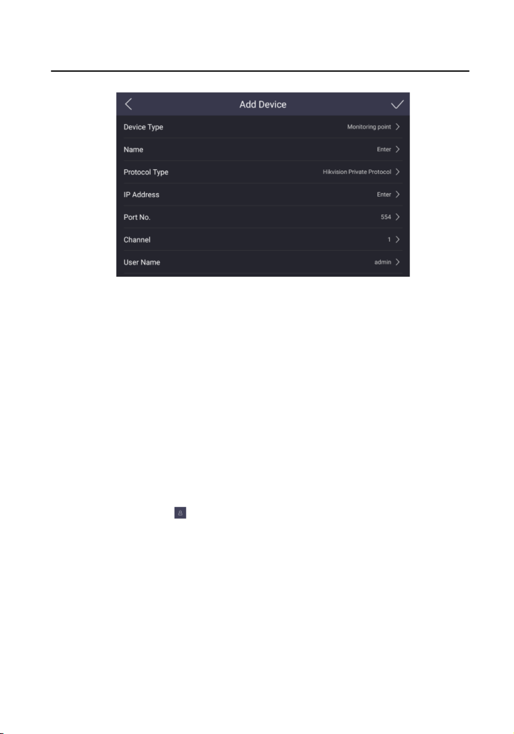
Figure 4-6 Add Camera
6. Device TypeSelect the as monitoring point.
7. Name Protocol Type IP Address Port No.Set , , , , Channel User Name, and
Password of the camera.
8. Tap to add.√
4.3 User Management
You can view the informaon ngerprints of the user and add the for admin.
Before You Start
Connect the ngerprint recognion rst. module to the device
Steps
1. Tap to enter the user management page.Conguraon →
Video Intercom Main Staon Conguraon Guide
17

Figure 4-7 User Management
2. Tap and enter the admin password to view the details.admin
Figure 4-8 Details
3. Tap to add refers to the on the page.Fingerprint → + ngerprints ps
Note
Up to 3 can be added.ngerprints
4.4 Synchronize Time
Video Intercom Main Staon Conguraon Guide
18

On the main page, tap the displayed area to synchronize manually. Hereme me
takes synchronizing via local me conguraon for example.
Steps
1. Tap to enter the page.Conguraon → → Time and Date sengs
Figure 4-9 Time and Date
2. Time ZoneSelect the .
3. Synchronize me.
-Congure the Date Time and manually.
-Slide the slider to enable the NTP Auto Time Synchronizaon funcon.
Set the synchronizing interval, enter the IP address of NTP server and port No.
4.5 Call Sengs
You can set the ringtone, ring call volume, volume and enableduraon, nocaon
the group call and microphone funcons.
Steps
1. Tap to enter the call page.Conguraon → sengs
Video Intercom Main Staon Conguraon Guide
19

Figure 4-10 Call Sengs
2. Set corresponding parameters.
Ringtone
There are 3 ringtones by default, and you can custom and import at most 4
ringtones via Batch Tool or Client Conguraon iVMS-4200 Soware.
Ringtone Duraon: duraon staon The maximum of main when it is called
without being accepted. Ringtone ranges from 30 s to 60 s.duraon
Volume Sengs
Adjust the call volume and volume.nocaon
Max. Call Duraon
The maximum of calling between main and other devices. Itduraon staon
ranges from 90 s to 120 s.
Group Call Switch
Slide to enable the group call then the device can receive more thanfuncon,
2 devices calling at the same me.
Microphone Input
Slide to enable the microphone input. You can use the goose neck microphone
to communicate.
4.6 Restore Main Staon
Video Intercom Main Staon Conguraon Guide
20

Steps
1. Tap and enter the admin password to enterConguraon → → Conguraon
the page.sengs
Note
Default admin password is the acvaon password.
2. Tap to enter the system maintenance page.
Figure 4-11 Maintenance
3. Tap Restore Default Sengs to restore the default and reboot the system.sengs
4. Tap Restore All to restore all parameters and reboot the system.
4.7 Upgrade
Before You Start
Plug in a USB ash driver or an SD card with upgrading package.
Steps
1. Tap and enter the admin password to enterConguraon → → Conguraon
the page.sengs
Note
Default admin password is the acvaon password.
2. Tap to enter the system maintenance page.
Video Intercom Main Staon Conguraon Guide
21

Figure 4-12 Maintenance
3. Tap to get the upgrading package to upgrade the device.Upgrade
4.8 Maintenance
SD Card
Tap Conguraon Conguraon → → and enter the admin password to
enter the page.sengs
Tap to enter the maintenance page.
Video Intercom Main Staon Conguraon Guide
22
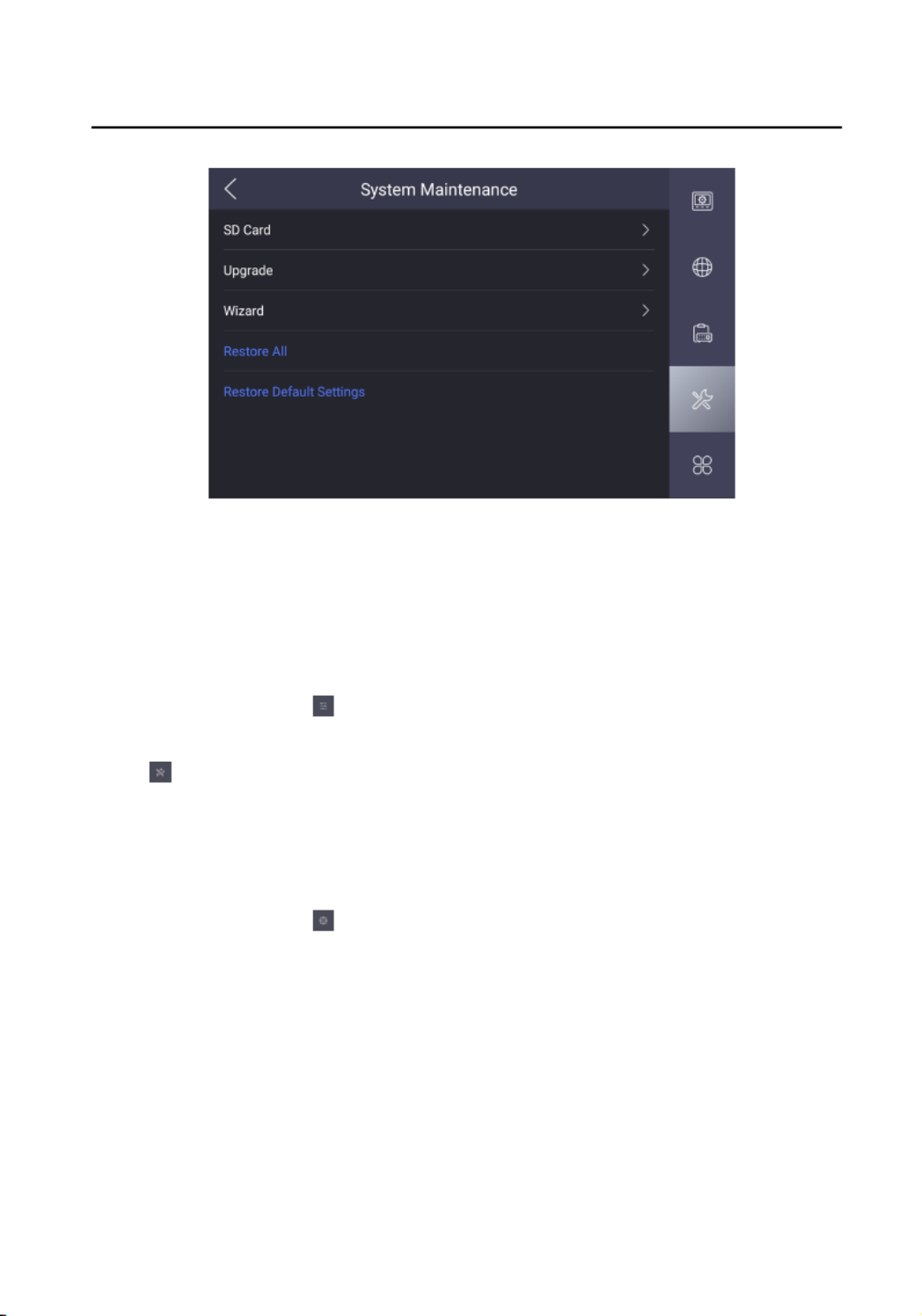
Figure 4-13 Maintenance
Tap to view the capacity of the SD card. You can format andSD Card
uninstall the SD card.
Wizard
Tap and enter the admin password toConguraon → → Conguraon
enter the page.sengs
Tap to enter the maintenance page.
Tap to Wizard congure the system quickly.
Permission Vericaon
Tap to enter the page.Conguraon → sengs
Video Intercom Main Staon Conguraon Guide
23

Figure 4-14 General Sengs
Slide to enable the permission You should vericaon funcon. vericate via
password or to awake the device.ngerprints
Brightness Adjustment
Tap to adjust the brightness.Conguraon →
Reboot
Tap to enter the page.Conguraon → sengs
Video Intercom Main Staon Conguraon Guide
24

Figure 4-15 Advanced Sengs
Tap to reboot the system.Reboot Device
Note
Please do not cut the power during reboong.
4.9 Device Informaon
View the device informaon, including the version model, serial No.,informaon,
LAN2 IP address, LAN2 Mac address and open source disclaimer.
Steps
1. Tap to enter the Device Sengs → → Device Informaon Informaon page.
2. View the version model, serial No., LAN2 IP address, LAN2 Macinformaon,
address and open source disclaimer.
3. Oponal: Tap to view the OSS statement.Open Source Disclaimer
Video Intercom Main Staon Conguraon Guide
25

5 Remote Conguraon via Web
Enter a short of your concept here descripon (oponal).
This is the start of your concept.
5.1 Acvate Device via Web
You are required to acvate rst seng the device by a strong password for it before
you can use the device.
Default parameters of the door staon are as follows:
●Default IP Address: 192.0.0.65.
●Default Port No.: 8000.
●Default User Name: admin
Steps
1. Power on the device, and connect the device to the network.
2. Enter the IP address into the address bar of the web browser, and click Enter to
enter the acvaon page.
Note
The computer and the device should belong to the same subnet.
3. Create and enter a password into the password eld.
4. Conrm the password.
5. OKClick to acvate the device.
5.2 Device Management
You can manage and view the linked device and camera on the page.
Click to enter the Device Management sengs page.
Video Intercom Main Staon Conguraon Guide
26

Add Linked Device
●Click to add the indoor Device List → Add staon, outerdoor doorstaon,
staon staon. or main Enter the parameters and click to add.OK
●Click . Enter the Device List → Import informaon of the device in the
template to import devices in batch.
Export Linked Device Informaon
Click , select the linked device, and click to export theDevice List Export
informaon to the PC.
Delete Linked Device
Click , select the linked device, and click Device List Delete to delete the
linked device.
Upgrade Linked Device
Click Device List → Upload Package BrowseUpdang , click to select the
upgrade to upload.le
Click , select the linked device, click Device List Timing Upgrade Enable, slide
Upgrading Device Start Time End TimeAutomacally, set and , and the
device will upgrade in the period.specic
Click , select the device, click Device List Upgrade Now, and the device will
upgrade now.
Note
You need to upload package before upgrading.updang
View Linked Device Upgrading Status
Click Device List → Upgrading , you can view the current linked devices
version.
Video Intercom Main Staon Conguraon Guide
27

View Linked Device Informaon
Click , select Device List Status Device Type and , the device informaon will
be displayed the page, including device No., IP Address, Serial No., model,
current version, room No., user name, network status You caninformaon.
click , , to edit, set and delete the linked device.
Add Camera
Click , enter the corresponding camera parameters, and clickCamera → Add
OK to add the camera.
Delete Camera
Click , select the camera, and click Device List Delete to delete the camera.
View Camera Informaon
Click to view the camera including camera name, No.,Camera informaon,
IP Address, channel No., port No., and protocol informaon. You can click
, , , to edit, set and delete the camera.
5.3 Parameters Sengs
Click to set the parameters of the device.Conguraon
Remote in iVMS-4200 and Batch Tool is the same as thatconguraon Conguraon
in Web. Here takes the in web for example.conguraon
Note
Run the browser, click to disable the Protected → Internet Opons → Security
Mode.
5.3.1 System Sengs
Follow the below to the system include Systeminstrucons congure sengs,
Sengs, Maintenance, Security, and User Management, etc.
Click System to enter the page.sengs
Video Intercom Main Staon Conguraon Guide
28
Specyfikacje produktu
| Marka: | Hikvision |
| Kategoria: | Interkom |
| Model: | DS-KM9503 |
Potrzebujesz pomocy?
Jeśli potrzebujesz pomocy z Hikvision DS-KM9503, zadaj pytanie poniżej, a inni użytkownicy Ci odpowiedzą
Instrukcje Interkom Hikvision

27 Marca 2025
27 Marca 2025
2 Marca 2025
11 Stycznia 2025
8 Października 2024
8 Października 2024
8 Października 2024
8 Października 2024
8 Października 2024
8 Października 2024
Instrukcje Interkom
- Interkom Philips
- Interkom SilverCrest
- Interkom Panasonic
- Interkom Alcatel
- Interkom BTicino
- Interkom Swann
- Interkom Viking
- Interkom ORNO
- Interkom Chamberlain
- Interkom Vimar
- Interkom Dahua Technology
- Interkom Emos
- Interkom Rollei
- Interkom Somfy
- Interkom DiO
- Interkom DataVideo
- Interkom Midland
- Interkom EtiamPro
- Interkom Planet
- Interkom Axis
- Interkom Abus
- Interkom Elro
- Interkom Marmitek
- Interkom Schwaiger
- Interkom ZKTeco
- Interkom Akuvox
- Interkom Busch-Jaeger
- Interkom Fibaro
- Interkom Hanwha
- Interkom Alecto
- Interkom Avidsen
- Interkom Foscam
- Interkom TOA
- Interkom Byron
- Interkom Monacor
- Interkom M-e
- Interkom Becken
- Interkom Smartwares
- Interkom Sygonix
- Interkom WHD
- Interkom Extel
- Interkom Acti
- Interkom Steren
- Interkom Siedle
- Interkom Valcom
- Interkom Chacon
- Interkom Konig
- Interkom DoorBird
- Interkom Gira
- Interkom HQ
- Interkom Russound
- Interkom Comelit
- Interkom Aiphone
- Interkom RTS
- Interkom Estom
- Interkom Nortek
- Interkom Bitron
- Interkom Hollyland
- Interkom Leviton
- Interkom Pentatech
- Interkom Ritto
- Interkom Syscom
- Interkom Elcom
- Interkom Pentatron
- Interkom CyberData Systems
- Interkom COMMAX
- Interkom Bintec-elmeg
- Interkom Eartec
- Interkom Gewiss
- Interkom Seco-Larm
- Interkom GEV
- Interkom Mobotix
- Interkom FlyingVoice
- Interkom Vibell
- Interkom Toucan
- Interkom 2N Telecommunications
- Interkom Louroe Electronics
Najnowsze instrukcje dla Interkom

28 Marca 2025
27 Marca 2025
27 Marca 2025
11 Marca 2025
10 Marca 2025
20 Lutego 2025
20 Lutego 2025
20 Lutego 2025
20 Lutego 2025
5 Lutego 2025