Instrukcja obsługi Suunto Vector
Suunto
Zegarek mierzący tętno
Vector
Przeczytaj poniżej 📖 instrukcję obsługi w języku polskim dla Suunto Vector (380 stron) w kategorii Zegarek mierzący tętno. Ta instrukcja była pomocna dla 14 osób i została oceniona przez 2 użytkowników na średnio 4.5 gwiazdek
Strona 1/380

1
USER’S GUIDE
CUSTOMER SERVICE CONTACTS
Suunto Oy Phone +358 9 875870
Fax +358 9 87587301
Suunto USA Phone 1 (800) 543-9124
Canada Phone 1 (800) 776-7770
European Call Center Phone +358 2 284 11 60
Suunto Website www.suunto.com
EN

2
TABLE OF CONTENTS
CHAPTER 1 INTRODUCTION .......................................................... 6
1.1 GENERAL INFORMATION .......................................................................................... 6
1.2 MAIN FUNCTIONS (MODES) ...................................................................................... 6
1.2.1 Backlight Features ......................................................................................... 7
1.2.2 Water Resistance .......................................................................................... 7
1.3 BUTTON FUNCTIONS ................................................................................................ 7
1.3.1 The [Mode] Button ......................................................................................... 7
1.3.2 The [+] Button ................................................................................................ 8
1.3.3 The [-] Button ................................................................................................. 8
1.3.4 The [Select] Button ........................................................................................ 8
1.4 LCD DISPLAY .............................................................................................................. 8
1.5 MEASUREMENTS AND UNITS ................................................................................. 10
1.5.1 Selecting the Units of Measurement ............................................................ 10
1.6 PRESSURE SENSOR CALIBRATION ........................................................................ 11
1.7 CARE AND MAINTENANCE ....................................................................................... 11
1.7.1 Battery Replacement ................................................................................... 12
CHAPTER 2 TIME MODE ............................................................... 13
2.1 HOW TO SET THE TIME .......................................................................................... 13
2.2 DAILY ALARM SUB MODE ........................................................................................ 15
2.2.1 How to Set the Daily Alarms ........................................................................ 15
2.3 STOPWATCH SUB MODE ........................................................................................ 16
2.3.1 How to Use the Stopwatch .......................................................................... 16
2.4 COUNTDOWN TIMER SUB MODE ........................................................................... 17
2.4.1 How to Set the Countdown Timer ................................................................ 18

3
2.4.2 How to Start the Countdown Timer .............................................................. 18
2.5 DUAL TIME SUB MODE (ALTIMAX , S-LANDER) ..................................................... 19
2.5.1 Setting the Dual Time Function ................................................................... 19
CHAPTER 3 ALTIMETER MODE .................................................... 20
3.1 SETTING THE ALTIMETER ....................................................................................... 21
3.2 ALTITUDE DIFFERENCE MEASUREMENT SUB MODE .......................................... 23
3.2.1 How to Start the Altitude Difference Measurement ...................................... 23
3.3 24-HOUR MEMORY SUB MODE ............................................................................... 24
3.4 LOGBOOK SUB MODE ............................................................................................. 24
3.4.1 How to Start and Stop a Logbook ................................................................ 26
3.4.2 Fast Cumulative Button ............................................................................... 26
3.5 LOGBOOK HISTORY SUB MODE ............................................................................ 27
3.5.1 Clearing the Logbook History ...................................................................... 28
CHAPTER 4 BAROMETER MODE .................................................. 28
4.1 PRESSURE DIFFERENCE MEASUREMENT SUB MODE ........................................ 29
4.1.1 How to Start the Pressure Difference Measurement.................................... 30
4.2 4-DAY MEMORY SUB MODE .................................................................................... 30
4.3 SEA LEVEL PRESSURE SUB MODE ........................................................................ 31
4.3.1 Setting the Sea Level Pressure ................................................................... 31
4.4 BAROMETRIC TREND INDICATOR .......................................................................... 32
CHAPTER 5 COMPASS MODE (VECTOR AND X-LANDER) ............ 32
5.1 BEARING TRACKING SUB MODE ............................................................................ 34
5.2 DECLINATION ADJUSTMENT SUB MODE ............................................................... 34
5.2.1 Setting the Local Declination ....................................................................... 35
5.3 CALIBRATING THE COMPASS ................................................................................. 35

4
CHAPTER 6 FREQUENTLY ASKED QUESTIONS ........................... 36
6.1 GENERAL .................................................................................................................. 36
6.1.1 Is the Wristop Computer waterproof? .......................................................... 36
6.1.2 How long will the battery last? ..................................................................... 36
6.1.3 What do the segments on the circumference mean? .................................. 37
6.1.4 Why do the segments on the circumference go to the left
(counterclockwise)? .................................................................................... 37
6.1.5 Why are there two symbols above the mode indicator bar and what do
they mean? ................................................................................................. 37
6.2 TIME .......................................................................................................................... 38
6.2.1 Why do the segments on the circumference increase and decrease when
I am in the Time mode? .............................................................................. 38
6.2.2 What is the longest time I can set in the timer? .......................................... 38
6.3 ALTIMETER ............................................................................................................... 38
6.3.1 How do you clear the logbook? ................................................................... 38
6.3.2 How does the logbook self-erase? .............................................................. 38
6.3.3 How many logbooks can you record? ......................................................... 38
6.3.4 What is the duration readout? ..................................................................... 39
6.3.5 What is the maximum capacity of total vertical ascent or descent feet/
meters in the logbook history? .................................................................... 39
6.3.6 If hiking from a level of 5,000 ft down hill to 3,000 ft and then back up to
8,000 feet, how is the Vector going to read this or average it out? ............. 39
6.3.7 Why does the vertical ascent/descent measurement show different
readings even though I am inside and staying in the same room? ............. 40
6.4 BAROMETER ............................................................................................................ 40
6.4.1 What is the little box on the top left of the display? ..................................... 40

5
6.4.2 Does the Wristop Computer show future trends in weather conditions? ..... 41
6.4.3 What does “absolute pressure” and “relative pressure” mean? .................. 41
6.4.4 What is temperature compensation? .......................................................... 41
6.5 COMPASS ................................................................................................................. 41
6.5.1 What is the purpose of the rotating outer bezel? ......................................... 41
6.5.2 Where do I find the correct declination for my area so I can set my
Wristop Computer? ..................................................................................... 42
6.6 EFFECT OF AIR TEMPERATURE ON ALTITUDE MEASUREMENT ........................ 42
CHAPTER 7 SPARE PARTS AVAILABLE ........................................ 44
CHAPTER 8 ABBREVIATIONS ....................................................... 45
CHAPTER 9 COPYRIGHT AND TRADEMARK NOTICE ................... 45
CHAPTER 10 CE COMPLIANCE ..................................................... 45
CHAPTER 11 LIMITS OF LIABILITY AND ISO 9001 COMPLIANCE 46
CHAPTER 12 DISPOSAL OF THE DEVICE ..................................... 46

6
CHAPTER 1 INTRODUCTION
1.1 GENERAL INFORMATION
The Wristop Computer is a reliable high precision electronic instrument, intended for recreational use. The
outdoor enthusiast who enjoys venturing in sports like skiing, kayaking, mountain climbing, hiking and biking
can rely on the Wristop Computer’s accuracy.
The ergonomically designed Wristop Computer weighs only 2 ounces or 55 grams and is accompanied by a
LCD featuring a large number display intended to be clearly visible in almost any condition.
Note: The Wristop Computer should not be substituted for acquiring measurements that require professional or
industrial precision and should not be used to acquire measurements when skydiving, hang gliding, paragliding,
gyrocopter riding and flying small aircraft.
IMPORTANT NOTE: A PULLOUT PAGE LOCATED ON THE FRONT INSIDE COVER OF THIS MANUAL
GRAPHICALLY ILLUSTRATES AND IDENTIFIES THE PROPERTIES OF THE WRISTOP COMPUTER AND
LCD DISPLAY. THIS PAGE IS DESIGNED TO FACILITATE THE USER’S UNDERSTANDING OF THE
FUNCTIONS AND PROCESSES TO SETUP THOSE FUNCTIONS.
1.2 MAIN FUNCTIONS (MODES)
Though the user’s guide applies to all the Wristop Computer models, functions and differences in operation of
the models are noted in the table below.
Functions Wristop Computer Models
Altimax S-Lander Vector X-Lander
Time YES YES YES YES
Altimeter YES YES YES YES
Barometer YES YES YES YES
Compass - - YES YES

7
In each of the functions, associated sub modes provide further enhancements to the usefulness of its owner.
All key features and sub modes are discussed in detail following this section.
Note: Wristop computer models Vector and X-Lander share the same features as well as Altimax and S-
Lander do. The difference is the Vector and Altimax are housed in a sturdy plastic case and the X-Lander and
S-Lander are set in brushed aluminium.
1.2.1 Backlight Features
The Wristop Computer has an electroluminescent backlight. This is initiated by pressing and holding the
[Mode] button for 2 seconds. The backlight will remain on for 5 seconds. Pressing the [Mode] button during
this time will restart the 5 second period, continuing the backlight feature.
1.2.2 Water Resistance
This product is water resistant. Water resistance is tested to 30m/100ft according to ISO 2281 standard
(www.iso.ch).
Note: The Wristop computer is not a dive instrument.
1.3 BUTTON FUNCTIONS
Four buttons are used to operate the Wristop Computer: [Mode], [+] (ON/OFF), [-] (Fast Bearing), and [Select].
1.3.1 The [Mode] Button
Is located on the top right of the Wristop Computer.
• In the main mode level, pressing the [Mode] button allows the user to select or move from one mode or
function to the next (TIME, ALTI, BARO, COMP).
• In the sub mode level, pressing the [Mode] button returns the user to the main mode level.
• In the setup process, pressing the [Mode] button accepts the changes or preferences. Pressing the button
again will return the user to the main mode level.
• Pressing the button for 2 seconds activates the backlight feature.

8
1.3.2 The [+] Button
Is located on the bottom right of the Wristop Computer.
• In the setup process, pressing the [+] button changes or scrolls the value upward.
• In the timing and logbook functions, this button can act as a start/stop (or On/Off) button.
1.3.3 The [-] Button
Is located on the bottom left of the Wristop Computer.
• In the setup process, pressing the [-] button changes or scrolls the value downward.
• For the Vector and X-Lander models this button is also known as the “Fast Bearing” button. Pressing
the [-] button in any of the main modes will quickly display the compass mode, showing either the normal
compass or bearing tracking feature (depending on what display has been chosen in the compass mode).
• For the Altimax and S-Lander models, this button is also called the “Fast Cumulative” button. Pressing the
[-] button in any of the main modes will quickly display the cumulative information of the current logbook
recording.
Note: Details of this feature can be located on Page 26 of this manual.
1.3.4 The [Select] Button
Is located on the top left of the Wristop Computer.
• In the main mode level, pressing the [Select] button allows the user to enter into the sub modes of the
particular function or return to the main mode the user is in.
• In the main mode or sub mode, pressing and holding the [Select] button for more than 2 seconds allows the
user to enter the setup process.
• In the setup process, the [Select] button allows the user to move between settable units or values and
determine preferences.
1.4 LCD DISPLAY
The display is designed to offer maximum clarity and simplicity to the user.
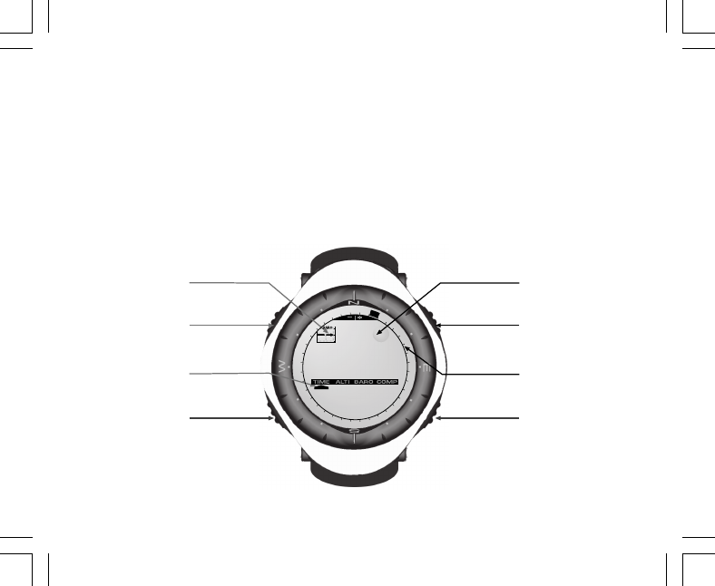
9
The display is divided into several regions or areas.
• The Outer Circumference encompasses the outer boundary of the LCD display. The peripheral segments
are found in the Outer Circumference.
• A Barometric Trend Indicator provides a quick reference for forecasting weather conditions.
• Field 1 displays values either numbers or text depending on the mode or sub mode the user is in.
• Field 2 displays large numbers and/or related unit of measure of the function.
• A Mode Indictor Bar displays the main modes (functions) of the Wristop Computer (a triangle arrow located
just below the bar indicates the mode the user is viewing).
• Field 3 displays numbers and/or text.
MODE
BUTTON
SELECT
BUTTON
- BUTTON + BUTTON
Mode Bar
Indicator Outer
Circumference
Bubble
Level
Barometer
Trend
Indicator
Field 1
Field 2
Field 3

10
1.5 MEASUREMENTS AND UNITS
The Wristop Computer supplies two units of measure: metric or imperial.
Metric Unit of Measure Imperial Unit of Measure
mft
m/min ft/min
°C °F
mbar inHg
1.5.1 Selecting the Units of Measurement
To change the unit of measure displayed:
1. Check the mode indicator. If the mode arrow is not on TIME, PRESS the [Mode] button until the arrow is
directly below TIME on the Mode Indicator Bar.
2. PRESS the [Mode] and [Select] buttons simultaneously and hold in for 3 seconds. Field 1 will display “SET”
momentarily and then display “UNI” (Fig. 43).
Note: If the user does not press any button for 1 minute in the setup mode, the display will automatically exit
setup.
WARNING: If the user presses the [Select] button (and does not hold for 2 seconds) while in the “UNI” setting
mode, the user will be in the Pressure Sensor Calibration. Refer to the next section for details.
3. PRESS the [Select] button and hold in for 2 seconds. Located to the right in Field 2, “m” or “ft” will begin to
flash.
4. PRESS the [+] button to toggle between “m” and “ft”.
5. At the unit of measure desired, PRESS the [Select] button to move to the next unit. Located below the “m” or
“ft” in Field 2, “mbar” or “inHg” will begin to flash.
6. PRESS the [+] button to toggle between “mbar” and “inHg”.
7. At the unit of measure desired, PRESS the [Select] button to move to the next unit. Located at the top right
in Field 1 (just above the bubble), °C or °F will begin to flash.
8. PRESS the [+] button to toggle between °C and °F.

11
9. At the unit of measure desired, PRESS the [Select] button to move to the next unit. Located at the top
center in Field 1, “m/min” or “ft/min” will begin to flash.
10 PRESS the [+] button to toggle between “m/min” and “ft/min”.
11 At the unit of measure desired, PRESS the [Mode] button to accept the changes. PRESS the [Mode] button
again to return to the main time mode.
Selecting the units of measurement is complete.
1.6 PRESSURE SENSOR CALIBRATION
This is a FACTORY SETTING CALIBRATION. If you are in this mode we highly suggest that you exit this setting
by pressing the [Mode] button. Calibrating this setting will ADVERSELY IMPACT all altitude and barometric
settings of the Wristop Computer.
In this setting, the user will be viewing “SNR” (Sensor) in Field 1. Do not press the [+] or [-] button to adjust the
pressure. Simply exit this setting by pressing the [Select] button to return to the “UNI” setting mode or by
pressing the [Mode] button to return to the main mode.
If the Pressure Setting Calibration has been altered, in error, please contact our Product Support Department.
1.7 CARE AND MAINTENANCE
Perform only the detailed processes discussed in this manual. Do not perform any other service to the
Wristop Computer or attempt to open the case or remove the buttons or the bezel.
Protect your Wristop Computer from shocks, extreme heat and prolonged exposure to direct sunlight. If not in
use, your Wristop Computer should be stored in a clean, dry environment at room temperature.
The Wristop Computer can be wiped clean with a lightly moistened (warm water) cloth. Applying a mild soap to
the area can clean stubborn stains or marks.
Avoid exposing the Wristop Computer to strong chemicals like gasoline, cleaning solvents, acetone, alcohol,
adhesives, and paint, as they will damage the unit’s seals, case and finish.
Never attempt to take the Wristop Computer apart or service it yourself. Make sure the area around the sensors
(backside of the instrument) is kept free of dirt and sand. Never insert any objects into the sensor openings of
the Wristop Computer.

12
1.7.1 Battery Replacement
The Wristop Computer operates on a three-volt lithium cell Type: CR 2430. The maximum life expectancy is
approximately 12-18 months.
A low battery-warning indicator is activated when 5-15 percent of the battery capacity is still available. When
this occurs we recommend replacement of the battery.
Extreme cold weather will activate the low battery-warning indicator. Though the indicator is activated, the
battery may not need to be replaced due to this condition. In temperatures above 10°C (50°F) and the low
battery warning indicator is activated, the battery will need to be replaced.
Note: Heavy use of the electroluminescent backlight, altimeter, and compass will significantly reduce the life of
the battery.
To replace the battery:
1. turn the Wristop Computer to view the backside;
2. insert a coin in the coin slot located on the battery compartment cover;
3. turn the coin counterclockwise to the open position marked on the back of the case;
4. remove the battery compartment cover;
5. remove the old cell from the battery compartment and ensure the o-ring and all surfaces are clean, dry and
not damaged. Do not stretch the o-ring;
6. place the new cell into the battery compartment (negative side down, positive side up);
7. ensure that the o-ring is in its place to keep the Wristop Computer waterproof. Place the battery compartment
cover back onto the backside of the Wristop Computer;
8. insert a coin back into the coin slot; and
9. turn the coin clockwise to the close position marked on the back of the case.
Note: Battery replacement should be performed with extreme care so as to ensure the Wristop Computer
continues to remain waterproof.It is the operator’s responsibility to take due care to ensure that the Wristop
Computer remains waterproof.
After every battery replacement, it is necessary to calibrate the magnetic sensor. Details on performing this
process are found in Calibrating the Compass section of this manual.

13
CHAPTER 2 TIME MODE
The Time Mode provides the user with:
• an adjustable 24/12 hour clock display;
• a calendar pre-programmed to the year 2089; and
• three sub modes: three daily alarms, stopwatch and countdown timer.
To view and use the Time mode:
Check the Mode Indicator Bar. If the mode arrow is not on TIME, PRESS the [Mode] button until the arrow is
directly below TIME on the bar.
In the TIME mode (Fig. 10):
• Field 1 displays the day of the week.
• Field 2 displays the current time.
• Field 3 displays the date (month/day).
• The Outer Circumference graphically displays time in seconds.
The Time mode and all sub modes can be adjusted through the setup program of the Wristop Computer.
2.1 HOW TO SET THE TIME
To set the Time:
1. PRESS the [Select] button and hold in for 2 seconds. Located in Field 3, the seconds will begin to flash
(Fig. 11).
2. PRESS the [+] button to scroll the seconds upward or
PRESS the [-] button to reset the seconds to zero.
3. At the seconds desired, PRESS the [Select] button to move to the next setting. Located on right of Field 2,
the minutes will begin to flash.
4. PRESS the [+] button to scroll the minutes upward or
PRESS the [-] button to scroll the minutes downward.

14
5. At the minutes desired, PRESS the [Select] button to move to the next setting. Located in the center of
Field 2, the hour will begin to flash.
6. PRESS the [+] button to scroll the hour upward or
PRESS the [-] button to scroll the hour downward.
7. At the hour desired, PRESS the [Select] button to move to the next setting. Located in Field 1, the 24 or 12
hour clock setting will begin to flash.
8. PRESS either the [+] or the [-] button to toggle between the 24hr and 12hr.
Note: If the 12 hour clock is chosen either AM/PM will appear below the hour in Field 2.
9. At the clock setting desired, PRESS the [Select] button to move to the next setting. Located in the center of
Field 2, the year will begin to flash (Fig. 12).
10. PRESS the [+] button to scroll the year upward or
PRESS the [-] button to scroll the year downward.
11. At the year desired, PRESS the [Select] button to move to the next setting. Located in the center of Field 3,
the month represented by a number will begin to flash.
12. PRESS the [+] button to scroll the month upward or
PRESS the [-] button to scroll the month downward.
13. At the month desired, PRESS the [Select] button to move to the next setting. Located to the right of Field 3,
the date will begin to flash.
14. PRESS the [+] button to scroll the date upward or
PRESS the [-] button to scroll the date downward.
Note: Once the user has determined the year, month and day, the Wristop Computer will supply the day of the
week in Field 1. The American month/day -view can not be changed to a day/month -view.
15. At the desired date, PRESS the [Mode] button to accept the changes and return to the main mode.
Note: If the user does not press any button for 1 minute in the setup mode, the display will automatically exit
setup.
Setting the time is now complete.

15
2.2 DAILY ALARM SUB MODE
The Wristop Computer allows the user to select and enter settings for up to three alarms.
In the TIME mode, PRESS the [Select] button once to enter this sub mode.
In the Daily Alarm sub mode (Fig. 39) :
• Field 1 displays “ON” or “OFF” (the activation status of a particular alarm),
• Field 2 displays the time of a particular alarm, and
• Field 3 displays the alarm (1, 2, or 3) the user is viewing.
Press the [+] or [-] button to select alarms 1,2, or 3. Then, change the settings in the manner described in the
following section.
2.2.1 How to Set the Daily Alarms
1. PRESS the [+] or the [-] button to select the desired alarm to be set (1,2, or 3).
2. PRESS the [Select] button and hold in for 2 seconds. Located in Field 1, the “ON” or “OFF” will begin to
flash.
3. PRESS either the [+] or the [-] button to toggle between “ON” and “OFF”.
4. At the setting desired, PRESS the [Select] button to move to the next setting. Located in the center of Field
2, the hour will begin to flash.
5. PRESS the [+] button to scroll the hour upward or
PRESS the [-] button to scroll the hour downward.
6. At the hour desired, PRESS the [Select] button to move to the next setting. Located on the right of Field 2,
the minutes will begin to flash.
7. PRESS the [+] button to scroll the minutes upward or
PRESS the [-] button to scroll the minutes downward.
8. At the minutes desired, PRESS the [Mode] button to accept the changes and exit the setup program. A
small bell will appear at the bottom left side in Field 2 to signify an alarm has been activated.
The Alarm setup is complete. To activate up to three alarms, please repeat steps 1-8 for the selected alarm (1,2, or 3).
Note: The Alarm volume can not be changed.

16
2.3 STOPWATCH SUB MODE
The Wristop Computer stopwatch sub mode can provide split time measurement and two finish times up to
23 hours 59 minutes and 59 seconds.
In the TIME mode, PRESS the [Select] button twice to enter this sub mode.
In the Stopwatch sub mode (Fig. 40):
• Field 1 displays the seconds and tenths of a second,
• Field 2 displays the current time, and
• Field 3 displays hours and minutes and to the far right “stopwatch”.
2.3.1 How to Use the Stopwatch
There are three timing modes the user can employ:
• an elapsed time measurement;
• a split time measurement; and
• a two finish time measurement.
In the elapsed time mode:
1. PRESS the [+] button to start, stop, and restart the stopwatch in the stopwatch sub mode.
2. PRESS the [-] button to reset the stopwatch to zero once the stopwatch has stopped.
In the split time mode:
1. PRESS the [+] button to start the stopwatch in the stopwatch sub mode.
2. PRESS the [-] button once to stop the stopwatch and to display a split time.
3. PRESS the [-] button a second time to release the split time display and resume the stopwatch.
4. PRESS the [+] button to stop the stopwatch.
5. PRESS the [-] button to reset the stopwatch to zero once the stopwatch has stopped.

17
In the two finish time mode:
1. PRESS the [+] button to start the stopwatch in the stopwatch sub mode.
2. PRESS the [-] button once to stop the stopwatch to display the finish time of the first person.
3. PRESS the [+] button to stop the stopwatch.
4. PRESS the [-] button a second time to release and display the finish time of the second person.
5. PRESS the [-] button to clear and to reset the stopwatch.
Note: When the stopwatch function is activated, the stopwatch will continue and remain in the background if
the user is in other modes or sub modes. The user can identify the stopwatch is still activated by the flashing
text “stopwatch” in Field 3.
2.4 COUNTDOWN TIMER SUB MODE
In the TIME mode, PRESS the [Select] button three times to enter this sub mode.
In the countdown timer sub mode (Fig. 41):
• Field 1 displays the seconds,
• Field 2 displays the current time, and
• Field 3 displays the hours and minutes and to the bottom far right the text “timer”.

18
2.4.1 How to Set the Countdown Timer
1. PRESS the [Select] button and hold in for 2 seconds. Located in Field 1, the seconds will begin to flash.
2. PRESS the [+] button to scroll the seconds upward or
PRESS the [-] button to scroll the seconds downward.
3. At the seconds desired, PRESS the [Select] button to move to the next setting. Located on right of Field 3,
the minutes will begin to flash.
4. PRESS the [+] button to scroll the minutes upward or
PRESS the [-] button to scroll the minutes downward.
5. At the minutes desired, PRESS the [Select] button to move to the next setting. Located in the center of Field
3, the hour will begin to flash.
6. PRESS the [+] button to scroll the hour upward or
PRESS the [-] button to scroll the hour downward.
7. At the hour desired, PRESS the [Mode] button to accept the changes and exit the setup program.
8. The countdown timer setup is complete.
2.4.2 How to Start the Countdown Timer
To start the countdown timer:
1. PRESS the [+] button to start, stop, and restart the timer in the countdown timer sub mode.
2. PRESS the [-] button to reset the timer to zero once the timer has stopped.
Note: When the countdown timer is activated, the countdown timer will continue and remain in the background
if the user is in other modes or sub modes. The user can identify the countdown timer still activated by the
flashing text “timer” in Field 3.

19
2.5 DUAL TIME SUB MODE (ALTIMAX AND S-LANDER)
Note: This feature applies to the Altimax and S-Lander Wristop Computers
In the TIME mode, PRESS the [Select] button four times to enter this sub mode.
In the dual time mode (Fig. 42):
• Field 1 displays dUA indicating “dual time”,
• Field 2 displays the current time, and
• Field 3 displays the dual time (e.g. your home time).
The user can display the seconds while in this sub mode by pressing the [+] button, in Field 3 the seconds will
appear for 10 seconds. Afterwards the display returns back to showing the dual time.
2.5.1 Setting the Dual Time
In the dual time sub mode:
1. PRESS the [Select] button and hold in for 2 seconds. Located in Field 3, the hours will begin to flash.
2. PRESS the [+] button to scroll the hours upward or
PRESS the [-] button to scroll the hours downward.
3. At the hour desired, PRESS the [Select] button to move to the next setting. Located in Field 3 to the right of
the hour value, the minutes will begin to flash.
4. PRESS the [+] button to scroll the minutes upward or
PRESS the [-] button to scroll the minutes downward.
5. At the minutes desired, PRESS the [Mode] button to accept the changes and exit the setup program.
6. The dual time setup is complete.
The dual time stays the same, even though the time in the main time mode is adjusted. For example, if you set
the dual time to show your home time, your home time will always be displayed in this sub mode even though
you travel to a different time zone and adjust the time in the main time mode.
Note: The dual time function is completely independent and does not affect the alarms or the memory functions.
These are dependent of the current local time.

20
CHAPTER 3 ALTIMETER MODE
The Altimeter mode provides the user with:
• an adjustable unit of measure either meter or feet: meter range -500 to 9,000; ft range -1,600 to 29,500;
• a resolution of 5m or 10ft;
• a display up-date on the rate of vertical movement in intervals of 1 second for 3 minutes, then every 10
seconds or less;
• an automatic 24-hour memory in one hour intervals showing altitude and vertical ascent/descent rate; and
• a logbook, recording approximately 3800 sets of data (one set = altitude, vertical ascent/descent rate and
time).
To view and use the Altimeter mode:
Check the Mode Indicator Bar. If the mode arrow is not on ALTI, PRESS the [Mode] button until the arrow is
directly below ALTI on the bar.
In the ALTIMETER mode (Fig. 1):
• Field 1 displays the vertical ascent or descent rate;
• Field 2 displays the current altitude in increments of 5 meters or 10 feet (depending on the unit of measure
selected); and
• Field 3 displays the current time.
• The Outer Circumference graphically displays the altitude in hundreds of meters or feet over a full thousand
where one complete circle is equivalent to 1000.
IMPORTANT NOTE: IN ORDER TO SET THE ALTITUDE IN THE ALTIMETER MODE, THE ALTITUDE MUST
BE KNOWN. THAT INFORMATION CAN BE FOUND BY UTILIZING A TOPOGRAPHICAL MAP, IDENTIFYING
THE CURRENT LOCATION WITH THE ASSOCIATED ALTITUDE MARKED. THE USER CAN PROCEED
AND FOLLOW THE INSTRUCTIONS, SETTING THE ALTIMETER, PROVIDED IN THE SECTION BELOW.
DETAILS REGARDING THE EFFECT OF AIR TEMPERATURE ON ALTITUDE MEASUREMENT ARE SHOWN
ON PAGE 41 OF THIS MANUAL.

21
IF THE ALTITUDE IS NOT KNOWN, THE USER CAN SET THE SEA LEVEL PRESSURE IN THE BAROMETRIC
MODE (REFER TO PAGE 31, SETTING THE SEA LEVEL PRESSURE).
SETTING THE SEA LEVEL PRESSURE WILL ADJUST THE ALTIMETER TO THE CURRENT ALTITUDE
WITHIN SOME TEN METERS OR FEW HUNDRED FEET.
INFORMATION ON THE CURRENT SEA LEVEL PRESSURE CAN BE OBTAINED THROUGH NEWSPAPERS,
LOCAL NEWS AND RADIO WEATHER REPORTS, THE LOCAL AIRPORT FACILITY OR THROUGH THE
INTERNET UNDER LOCAL WEATHER.
3.1 SETTING THE ALTIMETER
In setting the Altimeter, there are three processes that can be performed:
• the Reference Altitude (known altitude at the current location),
• the Altitude Alarm (signifies the user when a certain altitude, programmed, is reached), and
• the Logbook Recording Interval (allows the user to view the altitude and rate of vertical movement within a
chosen interval of time).
To begin:
1. PRESS the [Select] button and hold in for 2 seconds. Located in Field 1 is the text “RE” (indicating reference
altitude), located in Field 2, the current altitude will begin to flash (Fig. 2).
2. PRESS the [+] button to scroll the altitude upward or
PRESS the [-] button to scroll the altitude downwards.
3. At the desired reference altitude, either PRESS the [Mode] button to accept the changes and return to the
main mode or PRESS the [Select] button to move to the next setting. Located in Field 1, the “ON” or “OFF”
will begin to flash (Fig. 3).
4. PRESS either the [+] or the [-] button to toggle between the “ON” and “OFF” for the Altitude Alarm.
5. At the desired setting, PRESS the [Select] button to move to the next setting. Located in the center of Field
2, the alarm altitude will begin to flash.
6. PRESS the [+] button to scroll the altitude upward or
PRESS the [-] button to scroll the altitude downwards.

22
7. At the desired altitude, either PRESS the [Mode] button to accept the changes and return to the main mode
or PRESS the [Select] button to move to the next setting. Located in Field 1, the text INT and located in
Field 2 the time interval will begin to flash (Fig. 4).
8. PRESS either the [+] or the [-] button to scroll through the intervals. There are four time intervals 20 seconds,
1 minute, 10 minute or 60 minute.
Recommended interval to use:
Activity Interval
Skiing 20 sec or 1 minute
Biking 20 sec or 1 minute
Hiking 10 Minute
Mountaineering 10 minute or 60 minute
Note: In selecting the interval, the user chooses a) the time period for recording the altitude, the vertical ascent/
descent rate as well as the current time to be stored into the logbook and b) the timeout or maximum recording
time of a logbook. The shorter the interval the more accurate the information due to the fact the sampling rate
is faster. Timeouts are discussed on page 25.
9. At the desired interval, PRESS the [Mode] button to accept the changes and exit the setup program.
Once the user completes the process in setting the reference altitude of the current location to the known
altitude, the Wristop Computer will also correct the sea level pressure, and therefore, it will not be necessary for
this function to be set.
Note: If the user does not press any button for 1 minute in the setup mode, the display will automatically
exit setup.
Note: A 10-minute recording interval means that the Wristop Computer records data every 10 minutes.

23
3.2 ALTITUDE DIFFERENCE MEASUREMENT SUB MODE
In the Altimeter mode, PRESS the [Select] button once to enter this sub mode.
In the Altitude Difference measurement sub mode (Fig. 13):
• Field 1 displays the vertical ascent or descent rate;
• Field 2 displays the current altitude in increments of 5 meters or 10 feet depending on the unit of measure
selected; and
• Field 3 displays the running time; to the left of the time is the text “differ”.
• The Outer Circumference graphically displays the altitude in hundreds of meters or feet over a full thousand
where one complete circle is equivalent to 1000.
The running time is displayed up to 39 hours and 59 minutes; after which three dashes (-:--) appear on the
display in Field 3. If the user allows the difference measurement sub mode to remain on visual display continuously
for 12 hours, the Wristop Computer will automatically return to the main time mode.
This mode does continue in the background and allows the user to move to other modes and at the convenience
of the user can return to this sub mode to display the current status.
Note: The difference measurement mode is a relative measurement. Any change in the reference altitude
during the altitude difference measurement will effect the measured altitude. We recommend that the reference
altitude always be checked and set again prior to beginning a new measurement.
3.2.1 How to Start the Altitude Difference Measurement
1. PRESS the [Select] button and hold in for 2 seconds. Located in Field 1 is the text “SET”; located in Field
2, zero will begin to flash (Fig. 14).
2. PRESS the [Mode] button to accept the flashing zero and start the difference measurement.
If the user does not desire to begin the difference measurement, PRESS either the [+] or the [-] button to toggle
to the current altitude then PRESS the [Mode] button to exit the setup program.
Note: If the user does not press any button for 1 minute in the setup mode, the display will return to the main
mode without zeroing the altimeter.

24
3.3 24-HOUR MEMORY SUB MODE
In the Altimeter mode, PRESS the [Select] button twice to enter this sub mode.
In the 24-hour memory sub mode (Fig. 15):
• Field 1 displays the vertical ascent or descent rate;
• Field 2 displays the current altitude in increments of 5 meters or 10 feet depending on the unit of measure
selected; and
• Field 3 displays the particular hour and to the left the text “memory”.
• The Outer Circumference displays graphically the altitude in hundreds of meters or feet over a full thousand
where one complete circle is equivalent to 1000.
To view the information compiled in the 24-hr memory:
1. PRESS the [-] button to scroll back down in increments of one hour and view the vertical ascent/descent
rate and the altitude for that particular hour.
2. PRESS the [+] button to scroll back up.
Note: Replacing the battery will not erase this information.
3.4 LOGBOOK SUB MODE
In the Altimeter mode, PRESS the [Select] button three times to enter this sub mode. The logbook mode
features five displays. The displays automatically rotate showing the first display for 7 seconds then proceeds
showing displays 2 through 5 at 4 second intervals.
In the first display (Fig. 16):
• Field 1 displays the year;
• Field 2 displays the text “LO” with the current logbook number flashing; and
• Field 3 displays the month and day of the particular logbook number. To the left of the month/day, is the text
“Log Book”.
The user can PRESS the [-] to scroll down to view previous logs captured and then PRESS [+] to scroll up to the
current logbook.

25
The second display shows the ascent information for the particular logbook that is being viewed (Fig. 17).
• Field 1 displays the average ascent rate during the event;
• Field 2 displays the total vertical ascent ; and
• Field 3 displays the text “ASC” along with the text “Log Book” to the left.
The third display shows the descent information for the particular logbook that is being viewed (Fig. 18).
• Field 1 displays the average descent rate during the event;
• Field 2 displays the total vertical descent; and
• Field 3 displays the text “dSC” along with the text “Log Book” to the left.
The fourth display shows the number of laps (runs; either ascents or descents) completed for the particular
logbook that is being viewed (Fig. 19).
• Field 2 displays the total number of ascents or descents ; and
• Field 3 displays the text “LAP” along with the text “Log Book” to the left.
Note: A Lap is a vertical movement either ascent or descent equaling 150 ft (50 meters) or above.
The fifth display shows the time duration of recording information in the particular logbook that is being viewed
(Fig. 20).
• Field 2 displays the total time of the log ; and
• Field 3 displays the text “dUr” along with the text “Log Book” to the left.
Note: If the logbook is recording, based on the interval chosen the logbook will record up to that particular time
period. Once the time period has been reached the Wristop Computer, will alert the user that the logbook
recording has expired (known as a timeout). For setting the logbook interval refer to Setting the Altimeter on
Page 21.
The timeouts are as follows: Logbook intervals Maximum recording time
20 second 10 hours
1 minute 12 hours
10 minute 7 days
60 minute 10 days

26
3.4.1 How to Start and Stop a Logbook
For the Vector and X-Lander models:
In the Altimeter main mode or the difference measurement sub mode, PRESS the [+] button. A beep will be
heard and the flashing text “ Log Book” will appear in Field 3 to indicate the start of the recording.
Note: For the Vector and X-Lander models,while in the recording phase of the current logbook, the user will be
unable to view this data. The user can view this data only after the recording session has stopped, but previously
recorded logbooks can be viewed at any time.
The recording can be stopped by pressing the [+] a second time. A beep will be heard and the “Log Book” text
will be removed from Field 3 indicating recording has stopped.
Note: In order to prevent accidental starts/stops of a logbook, the Vector or X-Lander models should be in
another function other than the altimeter mode. If the logbook is activated the logbook will continue to recorded
even if the Vector or X-Lander is in another mode.
For the Altimax and S-Lander models:
Logbook recording starts by pressing the [+] button twice within 2 seconds. Logbook recording stops by
pressing the [+] button twice as well within 2 seconds.
Note: For the Altimax and S-Lander, Vector and X-Lander models logbooks are self-erasing and cannot be
cleared by the user.
Note: If you desire greater precision, start new logbooks more often or lower the recording interval.
3.4.2 Fast Cumulative Button
This function is furnished in the Altimax and S-Lander models. This allows the user to check the cumulative
vertical ascent/descent in feet or meters, as well as number of runs of the current logbook while recording.
Accessing this information is performed by pressing the [-] button in any of the main modes. When activated,
three displays will automatically rotate in intervals of four seconds.
• The first display shows the accumulative vertical ascent since the beginning of the current logbook.
• The second display shows the accumulative vertical descent since the beginning of the current logbook.
• And finally, the third display shows the number of runs accomplished during the current logbook.

27
After the third display is shown, the Altimax and S-Lander automatically return to the main mode in which the
user was viewing.
Note: During this process, pressing the [-] button allows the user to move on to the next of the three displays.
3.5 LOGBOOK HISTORY SUB MODE
The Logbook history shows a summation of all logs recorded.
In the Altimeter mode, PRESS the [Select] button four times to enter this sub mode. The logbook history mode
features four displays.
In the first display (Fig. 24):
• Field 1 displays the year when the logbook history has been last cleared;
• Field 2 displays the text “HIS”; and
• Field 3 displays the month and day when the logbook history has been last cleared. To the left of the month/
day, displayed is the text “Log Book”.
PRESS [+] to scroll through the different displays.
In the second display (Fig. 25):
• Field 1 displays the text “HI”;
• Field 2 displays the highest altitude recorded since the last date cleared; and
• Field 3 displays the date when it was reached with the text “Log Book” to the left.
In the third display (Fig. 26):
• Field 1 displays the text “ASC”;
• Field 2 and 3 show up to an 8 digit accumulative vertical ascent since the last reset. Field 2 is activated
when the value of the vertical ascent is beyond the 3 digit value displayed in Field 3.
In the fourth display (Fig. 27):
• Field 1 displays the text “dSC”;
• Field 2 and 3 show up to an 8 digit accumulative vertical descent since the last reset. Field 2 is activated
when the value of the vertical ascent is beyond the 3 digit value displayed in Field 3.

28
3.5.1 Clearing the Logbook History
To clear the history of the logbook (Fig. 28):
1. In any of the logbook history displays, PRESS the [Select] button and hold in for 2 seconds. Located in
Field 1 is the text “CLR”; in Field 2 the text “HIS”; and in Field 3, “nO” will begin to flash.
2. PRESS the [+] button to toggle between “YES” and “NO”.
3. PRESS the [Mode] button to accept the option “YES”.
The logbook history is erased and a new starting date is set to begin new cumulative measurements.
Note: If the user does not press any button for 1 minute in the setup mode, the display will automatically
exit setup.
We recommend that the logbook history be cleared prior to beginning logbook recording(s).
CHAPTER 4 BAROMETER MODE
The Barometer mode provides the user with:
• an adjustable unit of measure mbar or inHg; mbar range 300 to 1 100 mbar, inHg range 8.90 to 32.40;
• a resolution of 1 mbar or 0.05 inHg;
• a one hour interval measuring to estimate barometric trend;
• an automatic 4-day memory of atmospheric pressure for the last 6 hours in 1-hour intervals, thereafter, in 6-
hour intervals;
• temperature compensation (temperature does not effect the pressure within the specified temperature
range)
• a temperature range -20O to 60OC or -5O to 140OF; and
• a temperature resolution of 1O C or F.
Note: Body heat will effect temperature when the Wristop Computer is worn on the wrist. To achieve an
accurate reading remove the Wristop Computer from the wrist and allow at least 15 minutes before reading
the temperature.
If you’ve been in the barometric mode for more than 15 minutes with no rate of vertical movement, you should

29
allow 1 hour for the Wristop Computer to adjust the temperature. To acquire a quicker up-date of the temperature,
press the [Mode] button 4 times to re-enter the mode.
To view and use the Barometer mode:
Check the Mode Indicator Bar. If the mode arrow is not on BARO, PRESS the [Mode] button until the arrow is
directly below BARO on the bar.
In the Barometer mode (Fig. 5):
• Field 1 displays the current temperature.
• Field 2 displays the current absolute atmospheric pressure.
• Field 3 displays the current time.
• The Outer Circumference graphically displays the atmospheric pressure over 100 millibars or 1 inHg where
one complete circle is equivalent to 100 mbar/1 inHg, depending on the unit of measure chosen.
Note: The absolute pressure is the actual pressure in any location at any given time. Where as, sea level
pressure is the corresponding pressure at sea level.
4.1 PRESSURE DIFFERENCE MEASUREMENT SUB MODE
The pressure difference is not referring to the sea level pressure, but to the current barometric pressure
measured by the watch.
In the Barometer mode, PRESS the [Select] button once to enter this sub mode.
In the Pressure Difference Measurement submode (Fig. 30):
• Field 1 displays the change in temperature.
• Field 2 displays the change in atmospheric pressure.
• Field 3 displays the current time; to the left of the time is the text “differ”.
• The Outer Circumference graphically displays the change in pressure where one full circle equals 100
mbars or 1 inHg.
This mode does continue in the background and allows the user to move to other modes and at the user’s
convenience can return to this sub mode to show the current reading.

30
4.1.1 How to Start the Pressure Difference Measurement
1. PRESS the [Select] button and hold in for 2 seconds. Located in Field 1 is the text “SET”; located in Field
2, zero will begin to flash (Fig. 29).
2. PRESS the [Mode] button to accept the flashing zero and start the difference measurement.
If the user does not desire to begin the difference measurement, PRESS either the [+] or the [-] button to toggle
to the current barometric pressure reading, then PRESS the [Mode] button to exit the setup program.
Note: If the user does not press any button for 1 minute in the setup mode, the display will automatically exit
setup.
4.2 4-DAY MEMORY SUB MODE
In the Barometer mode, PRESS the [Select] button twice to enter this sub mode. This function allows the user
to follow changes in pressure that will assist forecasting changes in weather condition (i.e. storms).
In the 4-day memory sub mode (Fig. 31):
• Field 1 displays the day of the week the user is in;
• Field 2 displays the atmospheric pressure; and
• Field 3 displays the time and to the left the text “memory”.
• The Outer Circumference graphically displays the atmospheric pressure where one full circle equals
100 mbars or 1 inHg.
To view the information compiled in the 4-day memory:
PRESS the [-] button to scroll back down in increments of one hour for the first six hours, after that increments
are 6 hours.
PRESS the [+] button to scroll back up.
Note: Replacing the battery will not erase this information.

31
4.3 SEA LEVEL PRESSURE SUB MODE
Sea level pressure is pressure relative to sea level where as the pressure read in the main barometric display
is absolute pressure in the current location.
In the Barometer mode, PRESS the [Select] button three times to enter this sub mode.
In the sea level pressure sub mode (Fig. 32):
• Field 1 displays the text “SEA”;
• Field 2 displays the current sea level pressure; and
• Field 3 displays the current time.
4.3.1 Setting the Sea Level Pressure
Setting the sea level pressure can be used in setting the altitude measurement on the Wristop Computer if the
altitude is not known.
To set the sea level pressure:
1. PRESS the [Select] button and hold in for 2 seconds. Located in Field 2, the current sea level pressure will
begin to flash.
2. PRESS the [+] button to scroll the pressure upward or
PRESS the [-] button to scroll the pressure downward.
3. At the desired pressure, PRESS the [Mode] button to accept the changes and return to the main mode.
Once the user completes this process, the altitude measurement on the Wristop Computer is correct within a
range of some ten meters or few hundred feet.
Note: Information on the current sea level pressure can be obtained through newspapers, local news and radio
weather reports, the local airport facility or through the Internet under local weather.
If the user does not press any button for 1 minute in the setup mode, the display will automatically exit setup.

32
4.4 BAROMETRIC TREND INDICATOR
Located on the top left corner of the LCD display resides the Barometric Trend Indicator. This feature is always
displayed in all main modes providing the user a continual quick reference to analyze upcoming weather
conditions.
The Barometric trend is comprised of two lines forming an arrow. Each line represents a 3-hour period. The
right line represents the last 3 hours. The left line represents 3 hours prior to the last 3 hours. The line can
indicate 9 different patterns in the barometric trend.
Situation 6-3 hours ago Situation last 3 hours
Dropped heavy (>2 mbars/3hours) Dropping heavy (>2 mbars/3hours)
Dropped heavy (>2 mbars/3hours) Remaining stable
Dropped heavy (>2 mbars/3hours) Rising heavy (>2 mbars/3hours)
Remained stable Dropping heavy (>2 mbars/3hours)
Remained stable Remaining stable
Remained stable Rising heavy (>2 mbars/3hours)
Risen heavy (>2 mbars/3hours) Rising heavy (>2 mbars/3hours)
Risen heavy (>2 mbars/3hours) Remaining stable
Risen heavy (>2 mbars/3hours) Dropping heavy (>2 mbars/3hours)
Note: If the user remains at the same elevation, the barometric trend indicator can work as a weather forecasting
tool.
CHAPTER 5 COMPASS MODE (VECTOR AND X-LANDER)
Note: This function applies to the Vector and X-Lander.
The compass mode provides the user with:
• a cardinal or half cardinal point abbreviation;

33
• bearing degrees;
• a North-South arrow;
• a bearing track mode showing desired direction and actual bearing;
• a bubble level for accuracy reading +3 degrees (only in the Vector);
• a rotating bezel;
• a resolution of 1° for the bearing, +5° for North-South direction; and
• a declination correction feature.
To view and use the Compass Mode:
Check the Mode Indicator Bar. If the mode arrow is not on COMP, PRESS the [Mode] button until the arrow is
directly below COMP on the bar.
In the COMPASS mode (Fig. 6):
• Field 1 displays the cardinal or half-cardinal point.
• Field 2 displays the bearing in degrees.
• Field 3 displays the current time.
• The Outer Circumference graphically displays the North-South arrow where one-lit segment shows North
and three-lit segments show South.
The Wristop Computer provides a bubble level for the user to achieve a precise reading within +3 degrees. The
user should acquire a bearing by removing the Wristop Computer from the wrist. The user centers the liquid
bubble to ensure the Wristop Computer position is level and takes a reading.
The compass display is active for 45 seconds at a time. After this, the compass enters “sleep” mode and an “-
--°” indicator appears in the field 2. Reactivate the compass by pressing the [-] button.
Note: Compass readings should be performed away from objects possessing sources of magnetism. Avoid
buildings, large metal objects, power lines, loudspeakers, electric motors etc.
Always take bearings in the open air, not inside tents, caves, or other shelters.

34
5.1 BEARING TRACKING SUB MODE
The user can select to change from the cardinal point mode to the bearing track function and utilize the bearing
lock function in this mode for tracking purposes (Fig. 7).
In the compass main mode:
1. PRESS the [Select] button and hold in for 2 seconds. Located in Field 1, “OFF” will begin to flash (Fig. 8).
2. PRESS either the [+] or the [-] button to change the setting between “OFF” and “ON”.
3. At the selection desired, PRESS the [Select] button to move to the next setting. Located in Field 2, the
actual bearing in degrees will begin to flash (Fig. 9).
4. Turn the Wristop Computer to the desired direction. Lock the bearing displayed by pressing the [-] button.
5. Adjust the locked bearing, if necessary by pressing the [Select] button and then adjusting the value with the
[+] and [-] buttons.
6. At the desired bearing to track, PRESS the [Mode] button to accept the changes and exit the setup program.
Note: If the user does not press any button for 1 minute in the setup mode, the display will automatically exit
setup.
Note: Locking in the Bearing Tracking submode blocks the compass reading.
5.2 DECLINATION ADJUSTMENT SUB MODE
The Wristop Computer allows the user to compensate the difference between true north and magnetic north.
This process is accomplished by adjusting the declination, resulting in the user obtaining correct compass
readings.
In the Compass mode, PRESS the [Select] button once to enter this sub mode.
In the Declination Adjustment sub mode (Fig. 33):
• Field 1 displays the declination direction “OFF” where
OFF = no declination; W = West; E = East.
• Field 2 displays declination in degrees.
• Field 3 displays the text “dEC”.

35
5.2.1 Setting the Local Declination
1. PRESS the [Select] button and hold in for 2 seconds. Located in Field 1, “OFF” will begin to flash.
2. PRESS either the [+] or the [-] button to change the declination direction in Field 1.
3. At the direction desired, PRESS the [Select] button to move to the next setting. Located in Field 2, the
degrees will begin to flash.
4. PRESS the [+] button to scroll the degrees upward or
PRESS the [-] button to scroll the degrees downward.
5. At the degrees desired, PRESS the [Mode] button to accept the changes and exit the setup program.
Note: If the user does not press any button for 1 minute in the setup mode, the display will automatically exit
setup.
Local Declination is now set.
5.3 CALIBRATING THE COMPASS
A compass calibration should be done when the Wristop Computer is subject to close proximity of magnetic
sources, extreme cold weather, every time the battery is replaced or suspected that other environmental conditions
have effected the compass readings.
Note: We also recommend calibrating the compass before using the compass the first time and every time
leaving for a hike where the compass will be used.
To begin the calibration:
1. PRESS the [Select] button twice when in the main compass mode. Field 1 displays the text “CMP”. Field 3
displays the text “CAL” (Fig. 34).
2. PRESS the [Select] button and hold in for 2 seconds. Located in Field 2, the text “PUSH” will begin to flash
(Fig. 35).
3. PRESS the [-] button to start calibration.
4. In Field 2, 360° appears and the Outer Circumference displays all segments lit (Fig. 36). When this occurs,
hold the Wristop Computer level and start to slowly turn the device around a full circle in a level position. The

36
direction of turning does not matter. The lit segments will be turned off as the turning proceeds. When the
first full circle is completed, the instrument will inform the user within one minute of whether the calibration
was successful displaying the text “dOnE” in Field 2 (Fig. 37) or if the process needs to be repeated
displaying “PUSH” and “-” in Field 2.
Note: The user may need to perform the rotating of the compass more than twice around for the calibration to
be completed.
Note: During calibration, it is not necessary that all peripheral segments light up or turn off.
Note: If the text “FAIL” appears in Field 2 (Fig. 38), the battery should be removed and put back in before trying
to proceed with the calibration process. The removal of the battery will “reset” the unit.
5. Once the calibration is successful, PRESS the [Mode] button to accept the process and exit the calibration
mode.
Note: It is important to hold the Wristop Computer level during the calibration process to ensure accuracy.
The compass calibration is complete.
CHAPTER 6 FREQUENTLY ASKED QUESTIONS
6.1 GENERAL
6.1.1 Is the Wristop Computer water resistant?
Yes, it is water resistant to a depth of 30 meters (100 ft). Rain and other normal exposure to water will not effect
its operation. You can swim wearing your Wristop Computer. However, the Wristop Computer is NOT a diving
device.
6.1.2 How long will the battery last?
All users employ the product in different ways. Battery life depends mainly on how much the backlight, the
compass and the logbook are used. The low-battery warning symbol appears on the display when 5 to 15
percent of battery capacity remains. This should give the user plenty of time to safely change the battery.

37
6.1.3 What do the segments on the circumference mean?
In the Altimeter mode, one full circle equals 1,000 meters or 1,000 feet, therefore the segments on the
circumference graphically show the user the altitude over a full thousand. When using the difference measurement
function of the altimeter, the segments indicate the vertical difference in the elevation over a full thousand
either to the right if you’re ascending or to the left if you’re descending.
In the Barometer mode, one full circle equals 100 mbar or 1 inHg, and the segments indicate the pressure over
a full hundred mbar or over a full inHg. When using the difference measurement function of the barometer, the
segments indicate the change in atmospheric pressure either to the right if the pressure has risen or to the left
if the pressure has dropped.
In the main Compass mode, the segments indicate the North, i.e. the one segment indicates North and the
three segments point South. If you have set the compass to track a certain bearing, the segments on the
circumference indicate the difference between the direction in which you want to go and your actual bearing.
6.1.4 Why do the segments on the circumference go to the left
(counterclockwise)?
Normally, they always go to the right (clockwise) from the 12-noon position.
You are in the difference measurement mode and your unit is showing a decreasing value. In normal mode,
the segment display increases clockwise, but if you are in a mode that shows you differences (such as vertical
ascent/descent), all decreasing values go counterclockwise from the center position, and all increasing values
go clockwise. So, it is “minus” to the left (counterclockwise), and “plus” to the right (clockwise).
6.1.5 Why are there two symbols above the Mode Indicator Bar
and what do they mean?
The left-hand symbol indicates that the altitude alarm is activated and the right-hand symbol indicates that
one, two, or three daily alarms are activated.

38
6.2 TIME
6.2.1 Why do the segments on the circumference increase and
decrease when I am in the Time mode?
The main function of the segments is related to the Compass mode, where a division into 36 segments is
necessary due to the 360-degree scale of a compass. In the Time mode, the segments show the advancement
of seconds. Because the number of seconds differs from the number of degrees, it is impossible for the segments
to be consecutively lit up; they now light up or extinguish, thereby marking the passing of every second.
6.2.2 What is the longest time I can set in the timer?
The maximum range of the countdown timer is 23 hours 59 minutes and 59 seconds.
6.3 ALTIMETER
6.3.1 How do you clear the logbook?
The logbook is self-erasing and cannot be cleared by the user.
6.3.2 How does the logbook self-erase?
The logbook is circular and will start erasing itself when all the memory places are filled. There are approx.
3,800 memory places, each of which contain the altitude as well as the ascent/descent rate at that time (according
to the chosen interval, 20 seconds, 1 minute, 10 or 60 minutes).
When all the memory places are filled, the logbook starts recording new logs on top of the oldest recordings.
This is what is meant when we say the logbook is “self-erasing”.
You can clear the history of the logbook; i.e. where you get the cumulative ascent and descent information
based on the logs recorded into the logbook.
6.3.3 How many logbooks can you record?
The number of logs you can record into the logbook depends on the chosen interval and the length of each log.
For example, if your interval is 1 minute, you can get a total of 3,800 minutes of logs into the logbook. This
equals 2.64 days if the recording is continuous (24 hours = 1,440 minutes; 3,800/1,440=2.64).

39
To avoid excessive battery drain, the recording is not continuous. The recording functions have certain timeouts
(i.e. the recording will be turned off automatically after a certain time). The timeouts are shorter for the faster
interval and longer for the slower interval.
6.3.4 What is the duration readout?
The duration readout tells you how many hours and/or minutes the event recorded into the logbook lasted. For
example, if you’re hiking from 1 p.m. to 6 p.m. and the logbook is on during this time, the readout would show
a duration of 05:00 hours.
6.3.5 What is the maximum capacity of total vertical ascent or
descent feet/meters in the logbook history?
The maximum figure that can be shown on the display is 29,999.999 representing feet or meters depending on
the unit of measurement set. This should be enough for most users: 29,999.999 meters is roughly three-
quarters around the globe.
6.3.6 If hiking from a level of 5,000 ft down hill to 3,000 ft and
then back up to 8,000 feet, how is the Vector going to read this or
average it out?
There are several answers to this question related to different situations.
First, if you mean will Wristop Computer show accurate altitude information when ascending back to 8,000 ft
after having descended to 3,000 ft from 5,000 ft, the answer is yes if the barometric pressure hasn’t been
affected by weather changes. Since the altitude is shown based on the atmospheric pressure reading it will be
affected by pressure changes. But if the conditions are the same, and the reference altitude is set, the unit will
show quite accurate readings.
Second, if what you mean is how the Wristop Computer calculates the information shown in the logbook, this
is what it does: for the total ascent during the log (the logbook recording has been activated by the user when
starting out) it calculates the ascent from 3,000 ft to 8,000 ft, i.e. total ascent has been 5,000ft. For the descent
it calculates the descent from 5,000 ft to 3,000 ft, i.e. total descent 2,000 ft.

40
Third, if thinking about the difference measurement function and how this is affected by the example situation,
the Wristop Computer will show you the absolute difference between 5,000 ft and 8,000 ft (beginning and
end). The fact that you’ve been down to 3,000 ft in-between does not have an impact on the absolute vertical
altitude difference between starting point and finish.
Last, the automatic 24-hour memory will show this information in the following way: Say you are starting out
at 5,000 ft at noon, and then it takes you 2 hours to descend to 3,000 ft, and another five hours to reach 8,000
ft. The scrollable displays in the 24-hour memory shows you the altitude 5,000 ft at 12:00 am, e.g.4,000 ft at 1
p.m., 3,000 ft at 2 p.m., e.g. 4,000 ft 3 p.m., 5,000 ft at 4 p.m., 6,000 ft at 5 p.m., 7,000 ft at 6 p.m. and then 8,000
ft at 7 p.m.
These are the different cases in which the example situation will affect the readings of the Wristop Computer.
Most important to remember is to ALWAYS set the known reference altitude into the Wristop Computer. This is
the only way to get accurate altitude readings.
6.3.7 Why does the vertical ascent/descent measurement show
different readings even though I am inside and staying in the
same room?
The resolution of the vertical ascent/descent rate is 1 m/1 ft whereas the resolution of the altitude display is 5
m/10 ft, which means that the ascent/descent rate can show movement even though you remain at the same
altitude. This is caused by changes in pressure or even vertical movement within the 5 m/10 ft resolution range.
Indoors, even small, unnoticeable air currents cause changes in air pressure. For example, if you have a
window open at the other end of your house, the air current may affect a room at the other end of the building
so little that you do not notice it, but the sensors of the Wristop Computer do. Because the Wristop Computer
measures ascent and descent based on changes in air pressure, it interprets these changes as vertical movement.
6.4 BAROMETER
6.4.1 What is the little box on the top left of the display?
It is the barometric trend indicator that shows the general direction of weather changes. The display is based
on barometer measurements for the last 6 hours.

41
6.4.2 Does the Wristop Computer show future trends in weather
conditions?
No, the Wristop Computer continually accumulates data on barometric pressure existent within a 3 to 6 hour
window and displays general barometric trends in weather based on the accumulated data.
6.4.3 What does “absolute pressure” and “relative pressure”
mean?
Absolute pressure is the actual pressure in any location at any given time. Relative pressure on the other hand
equals the corresponding pressure at sea level for a certain altitude that you are at. For example, if you are at
an altitude of 1,000 m/3,300 ft the absolute pressure normally is around 900 mbar/26.60 inHg. The relative
pressure at sea level would then be around 1,013 mbar/29.90 inHg.
6.4.4 What is temperature compensation?
When the unit is temperature compensated, the altitude measurement of the unit is not affected by the
temperature of the unit itself. The unit can be worn on your wrist or placed on a table – it will in either case give
you the proper altitude reading providing the weather conditions have not changed. All Suunto Wristop Computers
are temperature compensated within the range –5 to 140 ° F / - 20 to +60 ° C.
6.5 COMPASS
6.5.1 What is the purpose of the rotating outer bezel?
The purpose of the rotating bezel is that people can use the instrument as a regular base plate compass if they
want to, and use the bezel to e.g. indicate North when in the bearing tracking mode or leaving the compass
display for another mode.
Also, it can be used to manually follow your vertical progress by using the lubber's line on the bezel to mark the
altitude from where you want to follow your progress (i.e. a zero point). You could also mark a certain altitude,
which is graphically shown by the segments on the circumference, to get an intermediate difference
measurement. However, the bezel is mainly related to the compass function.

42
6.5.2 Where do I find the correct declination for my area so I can
set my Wristop Computer?
Local declination, either E or W, is usually marked on maps with either one-degree or half-degree accuracy.
6.6 EFFECT OF AIR TEMPERATURE ON ALTITUDE
MEASUREMENT
The atmospheric pressure means the weight of air mass above the observer: at a higher altitude there is less
air than at a lower altitude. The principle of an altimeter is to measure the different air pressure between
different altitudes.
The air weight is affected by the outside temperature. Consequently the air pressure difference between two
altitudes is also dependant on temperature.
The altitude calculation of Wristop Computer is based on the air pressure at certain normal temperatures. Each
altitude has a definitive normal temperature. The normal temperatures at each altitude are presented in table 1.
Altitude (m) Altitude (ft) Temperature (C) Temperature (F)
above sea level above sea level
0 0 15.0 59.0
200 656 13.7 56.7
400 1312 12.4 54.3
600 1969 11.1 52.0
800 2625 9.8 49.6
1000 3281 8.5 47.3
1200 3937 7.2 45.0
1400 4593 5.9 42.6
1600 5250 4.6 40.3

43
1800 5906 3.3 37.9
2000 6562 2.0 35.6
2400 7874 -0.6 30.9
2800 9187 -3.2 26.2
3000 9843 -4.5 23.9
3400 11155 -7.1 19.2
3800 12468 -9.7 14.5
4000 13124 -11.0 12.2
4500 14765 -14.3 6.4
5000 16405 -17.5 0.5
5500 18046 -20.8 -5.4
6000 19686 -24.0 -11.2
Table 1. Normal temperatures corresponding to different altitudes
Now the altitude measurement error caused by an abnormal temperature gradient can be approximated as
follows. If the sum of the temperature offsets from the normal temperatures determined at two different
altitudes is 1 ºC, the altitude difference calculated by Wristop Computer is 0.2% off the real altitude
difference (When using imperial units the offset factor is 0.11% / 1 ºF). This is because the real temperatures
are not always the same as the normal temperatures. A higher than normal temperature causes the calculated
altitude difference to be smaller than the real altitude difference (your mountain ascent was actually higher).
Consequently, a lower than normal temperature causes the calculated altitude difference to be larger than the
real altitude difference (you did not ascend quite as high as displayed).
Table 2 shows an example in which the temperature offsets are positive. In this example, the reference altitude
is set at 1000 m. At 3000 m the altitude difference is 2000 m and Wristop Computer shows 80 m too little (20
ºC * 2000 m * 0.002/ºC = 80 m). Your actual altitude is thus 3080 m.

44
Lower point Higher point
Set reference altitude (real altitude) 1000 m
Displayed altitude 3000 m
Real outside temperature +17.5 ºC +6.5 ºC
Normal (table) temperature +8.5 ºC -4.5 ºC
Temperature offset (= real - normal) +9 ºC +11 ºC
Sum of temperature offsets +9 ºC + +11 ºC = 20 ºC
Table 2. Example using meters and Celsius
Table 3 shows an example in which the temperature offsets are negative This time imperial units are used.
The reference altitude is set at 3280 feet. At 9840 feet the altitude difference is 6560 feet and Wristop Computer
shows 100 feet too much (-14 ºF * 6560 ft * 0.0011/ºF = -100 ft). Your actual altitude is thus 9740 ft.
Lower point Higher point
Set reference altitude (real altitude) 3280 ft
Displayed altitude 9840 ft
Real outside temperature +36.3 ºF +18.9 ºF
Normal (table) temperature +47.3 ºF +23.9 ºF
Temperature difference (= real - normal) -9 ºF -5 ºF
Sum of temperature offsets -9 ºF + -5 ºF = -14 ºF
Table 3. Example using feet and Fahrenheit.
CHAPTER 7 SPARE PARTS AVAILABLE
Battery Replacement Kit (including battery, battery lid and o-ring)
Watch Straps in plastic (Vector/Altimax) or leather, velcro fabric and textile (S-Lander/X-Lander)
Extension strap in plastic
Bezel (Available only in Suunto Oy during maintenance)
Suunto Oy provides moderate-priced Wristop Computer service to its customers.
Batteries are usually available in sport and watch shops etc.

45
CHAPTER 8 ABBREVIATIONS
bEG - begin
HIS - history
dUA - dual time
dUR - duration
CMP - compass
CAL - calibration
bEA - bearing
CHAPTER 9 COPYRIGHT AND TRADEMARK NOTICE
This publication and its contents are proprietary to Suunto Oy and are intended solely for the use of its clients
to obtain knowledge and key information regarding the operation of all or any Wristop Computer product(s)
that includes the Vector, the X-Lander, the S-Lander and the Altimax.
Its contents shall not be used or distributed for any other purpose and/or otherwise communicated, disclosed
or reproduced without the prior written consent of Suunto Oy.
Suunto, Wristop Computer, Vector, X-Lander, Slander, Altimax and their logos are all registered or unregistered
trademarks of Suunto Oy. All rights are reserved.
While we have taken great care to ensure that information contained in this documentation is both comprehensive
and accurate, no warranty of accuracy is expressed or implied.
CHAPTER 10 CE COMPLIANCE
All Suunto Wristop Computers conform with the required European Union EMC directives 89/336/TEC.
dEF - default factory setting of pressure sensor,
corresponds to standard (1013 mbar or 29,90
inHg) airpressure at sea level
SNR - sensor (used in sensor calibration)
RE - reference altitude
CLR - clear
ASC - ascent
dSC - descent

46
CHAPTER 11 LIMITS OF LIABILITY AND ISO 9001
COMPLIANCE
If this product should fail due to defects in materials or workmanship, Suunto Oy will, at its sole option, repair or
replace it with new or rebuilt parts, free of charge, for two (2) years from the date of its purchase. This warranty
is extended only to the original purchaser and only covers failures due to defects in materials and workmanship
that occur during normal use while in the period of the warranty.
It does not cover damage or failures resulting in accident, misuse, neglect, mishandling, alteration or modifications
of the product, or any failure caused by operation of the product outside the scope of its published specifications,
or any causes not covered by this warranty.
There are no express warranties except as listed above.
Suunto Oy, Suunto Europe and Suunto USA/Canada shall in no event be liable for any incidental or consequential
damages arising from the use of or inability to use the product. Suunto Oy does not assume any responsibility
for losses or claims by third parties which may arise through the use of this device.
Suunto’s Quality Assurance System is certified by Det Norske Veritas to be ISO 9001 compliant in all SUUNTO
Oy’s operations (Quality Certificate No. 96-HEL-AQ-220).
CHAPTER 12 DISPOSAL OF THE DEVICE
Please dispose of the device in an appropriate way, treating it as electronic waste. Do
not throw it in the garbage. If you wish, you may return the device to your nearest Suunto
representative.

1
GUIDE DE L’UTILISATEUR
COORDONNÉES DU SERVICE CLIENTS
Suunto Oy Tél. +358 9 875870
Fax +358 9 87587301
Suunto USA Tél. 1 (800) 543-9124
Canada Tél. 1 (800) 776-7770
Centres d'appels en Europe Tél. +358 2 284 11 60
Site Web Suunto www.suunto.com
FR

2
TABLE DES MATIÈRES
CHAPITRE 1 INTRODUCTION .......................................................... 6
1.1 INFORMATIONS GÉNÉRALES ................................................................................... 6
1.2 MODES (FONCTIONS PRINCIPALES) ....................................................................... 6
1.2.1 Rétro-éclairage .............................................................................................. 7
1.2.2 Étanchéité ..................................................................................................... 7
1.3 FONCTIONS DES BOUTONS ..................................................................................... 7
1.3.1 Bouton [Mode] ............................................................................................... 7
1.3.2 Bouton [+] ...................................................................................................... 8
1.3.3 Bouton [-] ....................................................................................................... 8
1.3.4 Bouton [Select] .............................................................................................. 8
1.4 ÉCRAN LCD ................................................................................................................ 8
1.5 MESURES ET UNITÉS .............................................................................................. 10
1.5.1 Sélection des unités de mesure .................................................................. 10
1.6 ÉTALONNAGE DU CAPTEUR DE PRESSION .......................................................... 11
1.7 ENTRETIEN ............................................................................................................... 11
1.7.1 Changement de la pile ................................................................................ 12
CHAPITRE 2 MODE MONTRE (TIME) ............................................. 13
2.1 RÉGLAGE DE L’HEURE ............................................................................................ 13
2.2 FONCTION ALARME JOURNALIÈRE ....................................................................... 15
2.2.1 Réglage des alarmes journalières .............................................................. 15
2.3 FONCTION CHRONOMÈTRE ................................................................................... 16
2.3.1 Utilisation du chronomètre .......................................................................... 16
2.4 FONCTION COMPTE À REBOURS .......................................................................... 17
2.4.1 Réglage du compte à rebours ..................................................................... 18

3
2.4.2 Mise en route du compte à rebours ............................................................. 18
2.5 FONCTION HEURE D’UN DEUXIÈME FUSEAU HORAIRE (ALTIMAX, S-LANDER) 19
2.5.1 Réglage de l’heure d’un deuxième fuseau horaire ...................................... 19
CHAPITRE 3 MODE ALTIMÈTRE (ALTI) ......................................... 20
3.1 RÉGLAGE DE L’ALTIMÈTRE ..................................................................................... 21
3.2 FONCTION MESURE DE DÉNIVELÉ ........................................................................ 23
3.2.1 Activation de la fonction mesure de dénivelé ............................................... 23
3.3 FONCTION MÉMOIRE 24 HEURES .......................................................................... 24
3.4 FONCTION JOURNAL .............................................................................................. 24
3.4.1 Mise en route et arrêt d’un journal ............................................................... 26
3.4.2 Bouton de cumul rapide .............................................................................. 26
3.5 FONCTION HISTORIQUE DU JOURNAL ................................................................. 27
3.5.1 Effacement de l’historique du journal .......................................................... 28
CHAPTER 4 MODE BAROMÈTRE (BARO) ...................................... 28
4.1 FONCTION MESURE DE DIFFÉRENCE DE PRESSION ......................................... 29
4.1.1 Activation de la fonction mesure de différence de pression........................ 30
4.2 FONCTION MÉMOIRE 4 JOURS .............................................................................. 30
4.3 FONCTION PRESSION RÉDUITE AU NIVEAU DE LA MER .................................... 31
4.3.1 Réglage de la pression réduite au niveau de la mer .................................. 31
4.4 INDICATEUR DE TENDANCE BAROMÉTRIQUE ..................................................... 32
CHAPITRE 5 MODE BOUSSOLE (COMP) (VECTOR ET X-LANDER) 33
5.1 FONCTION SUIVI DE CAP ........................................................................................ 34
5.2 FONCTION CORRECTION DE DÉCLINAISON ....................................................... 35
5.2.1 Réglage de la déclinaison locale ................................................................. 35
5.3 ÉTALONNAGE DE LA BOUSSOLE ........................................................................... 36

4
CHAPITRE 6 FOIRE AUX QUESTIONS ........................................... 37
6.1 GÉNÉRALITÉS .......................................................................................................... 37
6.1.1 Mon ordinateur de poignet est-il étanche ? ................................................. 37
6.1.2 Combien de temps la pile dure-t-elle ? ....................................................... 37
6.1.3 Que représentent les segments de l’affichage circulaire ? ......................... 37
6.1.4 Pourquoi les segments de l’affichage circulaire vont-ils vers la gauche
(sens inverse des aiguilles d’une montre) ? ......................................................... 38
6.1.5 Pourquoi y a-t-il deux symboles au-dessus de l’indicateur de mode et que
signifient-ils ? .............................................................................................. 38
6.2 MONTRE ................................................................................................................... 38
6.2.1 Pourquoi les segments de l’affichage circulaire augmentent et diminuent
lorsque le mode TIME est activé ? ............................................................. 38
6.2.2 Quelle est la durée maximale du compte à rebours ? ................................. 38
6.3 ALTIMÈTRE ............................................................................................................... 39
6.3.1 Comment puis-je effacer le journal ? .......................................................... 39
6.3.2 Comment le journal s’efface-t-il de lui-même ? ........................................... 39
6.3.3 Combien de journaux puis-je enregistrer ? ................................................. 39
6.3.4 Qu’est-ce que l’affichage de la durée ? ....................................................... 39
6.3.5 Quelle est la capacité maximale de montée/descente totale (en mètres ou en
pieds) que l’historique du journal peut enregistrer ? ................................... 40
6.3.6 Si, lors d’une randonnée, je passe de 1600 m à 1000 m et qu’ensuite je
remonte à 2800 m, comment mon ordinateur de poignet interprète-t-il ces
déplacements ? .......................................................................................... 30
6.3.7 Pourquoi les mesures de montée/descente sont-elles différentes même si je
reste à l’intérieur d’une même pièce ? ........................................................ 41
6.4 BAROMÈTRE ............................................................................................................ 41

5
6.4.1 Que représente la petite case en haut à gauche de l’écran ? .................... 41
6.4.2 Mon ordinateur de poignet peut-il afficher les tendances météo à venir ? ... 42
6.4.3 Que signifient « pression absolue » et « pression relative » ? .................... 42
6.4.4 Qu’est-ce que la compensation de température ? ....................................... 42
6.5 BOUSSOLE ............................................................................................................... 42
6.5.1 Quel est le rôle de la couronne rotative ? .................................................... 42
6.5.2 Où puis-je trouver la déclinaison de mon emplacement pour la définir dans
mon ordinateur de poignet ? ....................................................................... 43
6.6 EFFET DE LA TEMPÉRATURE DE L’AIR SUR LES MESURES D’ALTITUDE ......... 43
CHAPITRE 7 PIÈCES DÉTACHÉES ................................................. 45
CHAPTER 8 ABRÉVIATIONS UTILISÉES SUR L’ÉCRAN LCD ........ 46
CHAPTER 9 DROITS D’AUTEUR ET DE PROPRIÉTÉ
INDUSTRIELLE .............................................................................. 46
CHAPTER 10 CONFORMITÉ CE ..................................................... 46
CHAPTER 11 LIMITES DE RESPONSABILITÉ ET CONFORMITÉ
ISO 9001 ........................................................................................ 47
CHAPTER 12 COMMENT SE DÉBARRASSER DE VOTRE
INSTRUMENT ................................................................................. 47

6
CHAPITRE 1 INTRODUCTION
1.1 INFORMATIONS GÉNÉRALES
Votre ordinateur de poignet est un instrument électronique de loisir fiable et de haute précision. Les amateurs
d’activités de plein air qui pratiquent le ski, le kayak, l’escalade, la randonnée ou le vélo peuvent compter sur
la précision de leur ordinateur de poignet. Vous disposez d’un instrument ergonomique, ne pesant que
55 grammes, et possédant un écran à cristaux liquides comprenant plusieurs affichages conçus pour être
visibles dans presque toutes les conditions.
Remarque : n'utilisez jamais votre ordinateur de poignet pour obtenir des mesures demandant une précision
professionnelle ou industrielle. Il ne doit pas non plus être utilisé pour obtenir des mesures nécessaires à la
pratique du parachutisme, du deltaplane, du parapente, du gyrocoptère, du planeur, de l'ULM, etc.
REMARQUE IMPORTANTE : UNE PAGE DÉTACHABLE SITUÉE EN DEUXIÈME DE COUVERTURE DE CE
MANUEL REPRÉSENTE DE FAÇON GRAPHIQUE LES PROPRIÉTÉS DE VOTRE ORDINATEUR DE
POIGNET ET DE SON ÉCRAN LCD. CETTE PAGE PERMET DE VOUS AIDER À COMPRENDRE LES
DIVERSES FONCTIONS DE CET INSTRUMENT AINSI QUE LES PROCÉDURES DE PARAMÉTRAGE DE
CES FONCTIONS.
1.2 MODES (FONCTIONS PRINCIPALES)
Bien que ce manuel s’applique à tous les modèles d’ordinateur de poignet, les modes et les différences
d’utilisation entre les modèles sont indiquées dans le tableau ci-dessous.
Modes Modèles d’ordinateur de poignet
Altimax S-Lander Vector X-Lander
TIME (Montre) OUI OUI OUI OUI
ALTI (Altimètre) OUI OUI OUI OUI
BARO (Baromètre) OUI OUI OUI OUI
COMP (Boussole) - - OUI OUI

7
Chaque mode possède ses propres fonctions.
Les modes et leurs fonctions sont présentés en détail dans les sections suivantes.
Remarque : les modèles Vector et X-Lander possèdent les mêmes fonctions que les ordinateurs de poignet
Altimax et S-Lander. Ils se distinguent de ces derniers par leur boîtier plastique solide, alors que les modèles
X-Lander et S-Lander possèdent un boîtier en aluminium brossé.
1.2.1 Rétro-éclairage
Votre ordinateur de poignet est équipé d’un rétro-éclairage électroluminescent. Pour l’activer, tenez enfoncé le
bouton [Mode] pendant 2 secondes. Le rétro-éclairage reste allumé pendant 5 secondes. Pendant ces
5 secondes, vous pouvez appuyer de nouveau sur le bouton [Mode] pour prolonger la durée du rétro-éclairage
de 5 secondes supplémentaires.
1.2.2 Étanchéité
Cet instrument est étanche. Son étanchéité a été testée jusqu’à 30 m/100 ft, conformément à la norme ISO 2281
(www.iso.ch).
Remarque : votre ordinateur de poignet n’est pas un instrument de plongée.
1.3 FONCTIONS DES BOUTONS
Les modes et les fonctions de votre ordinateur de poignet sont accessibles grâce à quatre boutons : [Mode],
[+], [-] et [Select].
1.3.1 Bouton [Mode]
Se trouve en haut à droite de l’écran.
• Dans les modes principaux, appuyez sur le bouton [Mode] pour passer d’un mode à un autre (TIME, ALTI,
BARO, COMP).
• Dans les fonctions des modes, appuyez sur le bouton [Mode] pour revenir aux modes principaux.
• En mode paramétrage, appuyez sur le bouton [Mode] pour valider les réglages effectués. Appuyez de
nouveau sur ce bouton pour revenir aux modes principaux.
• Tenez enfoncé ce bouton pendant 2 secondes pour activer le rétro-éclairage.

8
1.3.2 Bouton [+]
Se trouve en bas à droite de l’écran.
• En mode paramétrage, appuyez sur le bouton [+] pour changer ou augmenter les valeurs.
• Dans les fonctions de chronométrage et de journal, ce bouton sert de bouton « On/Off ».
1.3.3 Bouton [-]
Se trouve en bas à gauche de l’écran.
• En mode paramétrage, appuyez sur le bouton [-] pour changer ou diminuer les valeurs.
• Pour les modèles Vector et X-Lander ce bouton permet également d’activer la fonction suivi de cap. Appuyez
sur le bouton [-] dans n’importe quel mode principal pour faire rapidement apparaître le mode COMP,
affichant soit la boussole normale soit la fonction suivi de cap (selon l’affichage sélectionné dans le mode
COMP).
• Pour les modèles Altimax et S-Lander ce bouton permet également d’activer la fonction cumul rapide.
Appuyez sur le bouton [-] dans n’importe quel mode principal pour faire rapidement apparaître les informations
recueillies par le journal en cours d’enregistrement.
Remarque : pour plus d’informations sur cette fonction, reportez-vous à la page 26 de ce manuel.
1.3.4 Bouton [Select]
Se trouve en haut à gauche de l’écran.
• Dans les modes principaux, le bouton [Select] permet soit d’accéder aux fonctions du mode soit de revenir
au mode principal.
• Dans les modes ou les fonctions des modes, tenez enfoncé le bouton [Select] pendant plus de 2 secondes
pour passer en mode paramétrage.
• En mode paramétrage, le bouton [Select] permet de faire défiler les paramètres ajustables (unités ou
valeurs) et de déterminer vos préférences.
1.4 ÉCRAN LCD
Cet écran est conçu de façon à être simple et facile à lire.
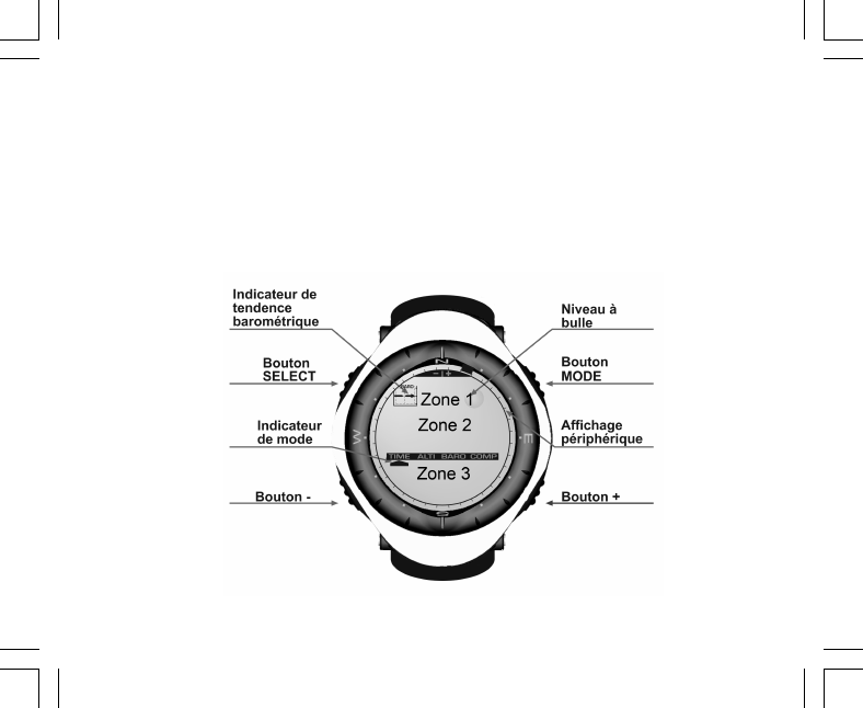
9
L’écran est divisé en plusieurs zones.
• L’écran LCD possède en son pourtour un affichage circulaire segmenté.
• Un indicateur de tendance barométrique vous permet de prévoir d’un simple coup d’œil les conditions
météo à venir.
• La zone 1 affiche des valeurs (des chiffres ou du texte) selon le mode ou la fonction sélectionné.
• La zone 2 affiche des gros chiffres et/ou l’unité de mesure associée à la fonction sélectionnée.
• Sous la zone 2, une barre affiche les modes principaux de votre ordinateur de poignet (une flèche triangulaire
située juste au-dessous de cette barre indique le mode actuellement sélectionné).
• La zone 3 affiche des chiffres et/ou du texte.

10
1.5 MESURES ET UNITÉS
Votre ordinateur de poignet supporte deux systèmes de mesure : le système métrique et le système britannique.
Système métrique Système britannique
mft
m/min ft/min
°C °F
mbar inHg
1.5.1 Sélection des unités de mesure
Pour changer les unités de mesure de votre ordinateur de poignet :
1. Consultez l’indicateur de mode. En appuyant sur le bouton [Mode], faites passer la flèche triangulaire sous
l’indication TIME.
2. Tenez enfoncés en même temps et pendant 3 secondes les boutons [Mode] et [Select]. « SET » apparaît
momentanément dans la zone 1, suivi de « UNI » (Fig. 43).
Remarque : si vous n’appuyez sur aucun bouton avant une minute lorsque vous vous trouvez en mode
paramétrage, celui-ci disparaît.
ATTENTION : en mode UNI, si vous appuyez sur le bouton [Select] sans le tenir enfoncé pendant 2 secondes,
vous activez le mode étalonnage du capteur de pression. Reportez-vous à la section suivante pour plus de
détails à ce sujet.
3. Tenez le bouton [Select] enfoncé pendant 2 secondes. « m » ou « ft » se met à clignoter à droite dans la
zone 2.
4. Appuyez sur le bouton [+] pour choisir « m » ou « ft ».
5. Une fois l’unité de mesure sélectionnée, appuyez sur le bouton [Select] pour passer à l’unité suivante.
Sous « m » (ou « ft »), toujours dans la zone 2, « mbar » ou « inHg » se met à clignoter.
6. Appuyez sur le bouton [+] pour choisir « mbar » ou « inHg ».
7. Une fois l’unité de mesure sélectionnée, appuyez sur le bouton [Select] pour passer à l’unité suivante. En
haut à droite dans la zone 1 (juste au-dessus de la bulle), °C ou °F se met à clignoter.
8. Appuyez sur le bouton [+] pour choisir °C ou °F.

11
9. Une fois l’unité de mesure sélectionnée, appuyez sur le bouton [Select] pour passer à l’unité suivante. En
haut et au centre de la zone 1, « m/min » ou « ft/min » se met à clignoter.
10.Appuyez sur le bouton [+] pour choisir « m/min » ou « ft/min ».
11. Une fois l’unité de mesure sélectionnée, appuyez sur le bouton [Mode] pour valider les réglages effectués.
Appuyez de nouveau sur le bouton [Mode] pour revenir au mode principal TIME.
La phase de sélection des unités est terminée.
1.6 ÉTALONNAGE DU CAPTEUR DE PRESSION
Le capteur a déjà été étalonné en usine. Si vous accédez à ce mode par mégarde, nous vous conseillons d’en
sortir en appuyant sur le bouton [Mode]. Si vous changez l’étalonnage du capteur, tous les paramètres d’altitude
et de pression barométrique de votre ordinateur de poignet seront faussés.
Lorsque vous êtes dans ce mode, « SNR » apparaît dans la zone 1. N’appuyez surtout pas sur les boutons [+]
ou [-] ou vous risquez de changer la pression définie. Quittez simplement ce mode en appuyant sur le bouton
[Select] pour revenir au mode UNI ou sur le bouton [Mode] pour revenir au mode principal.
Si vous modifiez l’étalonnage du capteur de pression par erreur, veuillez contacter notre service technique et
commercial.
1.7 ENTRETIEN
Ne suivez que les procédures décrites dans ce manuel. N’effectuez aucun autre entretien et n’essayez jamais
d’ouvrir le boîtier de votre ordinateur de poignet ni de retirer sa couronne.
Protégez votre ordinateur de poignet des chocs, des chaleurs extrêmes et des expositions prolongées aux
rayons du soleil. Lorsqu’il n’est pas utilisé, rangez votre ordinateur de poignet dans un endroit propre et sec, à
température ambiante.
Pour nettoyer votre ordinateur de poignet, vous pouvez l’essuyer avec un linge légèrement imbibé d’eau tiède.
En cas de marques ou de taches persistantes, appliquez un savon doux sur la zone en question.
Évitez d’exposer votre ordinateur de poignet à des produits chimiques forts tels que l’essence, les solvants de
nettoyage, l’acétone, l’alcool, les adhésifs et les peintures, qui risquent de détériorer les joints, le boîtier et
l’aspect de l’instrument.

12
N’essayez jamais de démonter ou d’entretenir votre ordinateur de poignet vous-même. Éliminez les saletés et
les éventuels grains de sable qui peuvent se trouver aux alentours des capteurs (à l’arrière de l’instrument).
N’insérez jamais d’objet pointu dans les ouvertures des capteurs de votre ordinateur de poignet.
1.7.1 Changement de la pile
Votre ordinateur de poignet est alimenté par une pile au lithium 3 volts de type CR 2430. La durée de vie
maximum de la pile est d’environ 12-18 mois.
Un indicateur de niveau de pile faible apparaît lorsque la pile atteint 5-15 % de sa capacité maximale. Si cet
indicateur apparaît, nous vous recommandons de changer la pile sans attendre.
Des températures extrêmement froides peuvent également faire apparaître cet indicateur. Il est cependant
inutile de changer la pile à ce moment-là. Par contre, si cet indicateur apparaît par des températures supérieures
à 10°C (50°F), nous vous suggérons de changer la pile.
Remarque : une utilisation intensive du rétro-éclairage, de l’altimètre et de la boussole réduit considérablement
la durée de vie de la pile.
Pour changer la pile :
1. retournez votre ordinateur de poignet,
2. insérez une pièce de monnaie dans l’encoche située sur le couvercle du logement de pile,
3. tournez le couvercle dans le sens inverse des aiguilles d’une montre pour l’aligner avec les repères de
position ouverte situés à l’arrière du boîtier,
4. retirez le couvercle du logement de pile,
5. sortez l’ancienne pile et assurez-vous que le joint et les surfaces du logement de pile sont propres, secs et
en bon état. N’appliquez aucune tension sur le joint,
6. insérez la pile neuve dans son logement en orientant sa borne (+) vers le haut,
7. vérifiez que le joint est bien en place, de sorte à conserver les propriétés d’étanchéité de votre ordinateur de
poignet. Refermez le logement de la pile,
8. insérez la pièce de monnaie dans l’encoche du couvercle, et
9. tournez le couvercle dans le sens des aiguilles d’une montre pour l’aligner avec les repères de position
fermée situés à l’arrière du boîtier.

13
Remarque : soyez extrêmement prudent pour changer la pile de votre ordinateur de poignet, pour conserver
ses propriétés d’étanchéité. En tant qu’utilisateur, vous êtes responsable de l’étanchéité de votre ordinateur
de poignet.
À chaque fois que vous changez la pile, vous devez procéder à l’étalonnage du capteur magnétique. Vous
trouverez davantage de détails à ce sujet dans la section « Étalonnage de la boussole » de ce manuel.
CHAPITRE 2 MODE MONTRE (TIME)
Le mode TIME possède :
• un affichage de l’heure au format 12/24 heures,
• un calendrier préprogrammé jusqu’en 2089, et
• trois fonctions : trois alarmes journalières, un chronomètre et un compte à rebours.
Pour visualiser et utiliser le mode TIME :
Consultez l’indicateur de mode. En appuyant sur le bouton [Mode], faites passer la flèche triangulaire sous
l’indication TIME.
En mode TIME (Fig. 10) :
• La zone 1 affiche le jour de la semaine.
• La zone 2 affiche l’heure actuelle.
• La zone 3 affiche la date (mois/jour).
• L’affichage circulaire affiche les secondes.
Le mode TIME et ses fonctions se règlent via le mode paramétrage de votre ordinateur de poignet.
2.1 RÉGLAGE DE L’HEURE
Pour régler l’heure :
1. Tenez le bouton [Select] enfoncé pendant 2 secondes. Les secondes se mettent à clignoter dans la zone
3 (Fig. 11).
2. Appuyez sur le bouton [+] pour augmenter les secondes ou appuyez sur le bouton [-] pour remettre les
secondes à zéro.
.

14
3. Une fois les secondes définies, appuyez sur le bouton [Select] pour passer au réglage suivant. Les minutes
se mettent à clignoter à droite dans la zone 2.
4. Appuyez sur le bouton [+] pour augmenter les minutes ou appuyez sur le bouton [-] pour les diminuer.
5. Une fois les minutes définies, appuyez sur le bouton [Select] pour passer au réglage suivant. Les heures
se mettent à clignoter au centre de la zone 2.
6. Appuyez sur le bouton [+] pour augmenter les heures ou sur le bouton [-] pour les diminuer.
7. Une fois les heures définies, appuyez sur le bouton [Select] pour passer au réglage suivant.
« 12h » ou « 24h » se met à clignoter dans la zone 1.
8. Appuyez sur le bouton [+] ou le bouton [-] pour passer de l’affichage 24 heures à l’affichage 12 heures.
Remarque : si vous choisissez l’affichage 12 heures, l’indication « AM/PM » apparaît sous l’heure dans la
zone 2.
9. Une fois l’heure définie, appuyez sur le bouton [Select] pour passer au réglage suivant. L’année se met à
clignoter au centre de la zone 2 (Fig. 12).
10.Appuyez sur le bouton [+] pour augmenter l’année ou sur le bouton [-] pour la diminuer.
11.Une fois l’année définie, appuyez sur le bouton [Select] pour passer au réglage suivant. Le mois, représenté
par un ou deux chiffres, se met à clignoter au centre de la zone 3.
12.Appuyez sur le bouton [+] pour augmenter le mois ou sur le bouton [-] pour le diminuer.
13.Une fois le mois défini, appuyez sur le bouton [Select] pour passer au réglage suivant. La date se met à
clignoter, à droite dans la zone 3.
14.Appuyez sur le bouton [+] pour augmenter la date ou sur le bouton [-] pour la diminuer.
Remarque : une fois que vous avez défini l’année, le mois et le jour, votre ordinateur de poignet affichera le
jour de la semaine dans la zone 1. L’affichage américain mois/jour ne peut pas être changé en affichage jour/
mois.
15.Une fois la date définie, appuyez sur le bouton [Mode] pour valider les réglages effectués et revenir au
mode principal.
Remarque : si vous n’appuyez sur aucun bouton avant une minute lorsque vous vous trouvez en mode
paramétrage, celui-ci disparaît.
Le réglage du mode TIME est terminé.

15
2.2 FONCTION ALARME JOURNALIÈRE
Votre ordinateur de poignet vous permet de régler jusqu’à trois alarmes.
En mode TIME, appuyez une fois sur le bouton [Select] pour accéder à cette fonction.
Affichages de la fonction alarmes journalières (Fig. 39) :
• La zone 1 affiche « ON » ou « OFF » (état d’activation de l’alarme sélectionnée),
• La zone 2 affiche l’heure de l’alarme sélectionnée, et
• La zone 3 affiche le numéro de l’alarme (1, 2 ou 3) actuellement affichée.
Appuyez sur les boutons [+] ou [-] pour sélectionner l’alarme 1,2 ou 3, puis réglez l’alarme sélectionnée selon
les instructions données ci-dessous.
2.2.1 Réglage des alarmes journalières
1. Appuyez sur les boutons [+] ou [-] pour sélectionner une alarme (1,2 ou 3).
2. Tenez le bouton [Select] enfoncé pendant 2 secondes. L’indication « ON » ou « OFF » se met à clignoter
dans la zone 1.
3. Appuyez sur le bouton [+] ou le bouton [-] pour choisir entre « ON » et « OFF ».
4. Une fois ce paramètre défini, appuyez sur le bouton [Select] pour passer au réglage suivant. L’heure se
met à clignoter au centre de la zone 2.
5. Appuyez sur le bouton [+] pour augmenter l’heure ou sur le bouton [-] pour la diminuer.
6. Une fois l’heure définie, appuyez sur le bouton [Select] pour passer au réglage suivant. Les minutes se
mettent à clignoter à droite dans la zone 2.
7. Appuyez sur le bouton [+] pour augmenter les minutes ou sur le bouton [-] pour les diminuer.
8. Une fois les minutes définies, appuyez sur le bouton [Mode] pour valider les réglages effectués et quitter le
mode paramétrage. Une petite cloche apparaît en bas à gauche de la zone 2 pour indiquer qu’une alarme
a été activée.
Le réglage de l’alarme est terminé. Pour activer et régler les autres alarmes, veuillez répétez les étapes 1 à 8
pour chaque alarme sélectionnée (1,2 ou 3).
Remarque : le volume des alarmes ne peut pas être changé.

16
2.3 FONCTION CHRONOMÈTRE
Le chronomètre de votre ordinateur de poignet permet de prendre des temps intermédiaires et deux temps de
course pouvant aller jusqu’à 23 heures 59 minutes et 59 secondes.
En mode TIME, appuyez deux fois sur le bouton [Select] pour accéder à cette fonction.
Affichages de la fonction chronomètre (Fig. 40) :
• La zone 1 affiche les secondes et les dixièmes de seconde,
• La zone 2 affiche l’heure actuelle, et
• La zone 3 affiche les heures et les minutes et, sur la droite, l’indication « STOP WATCH ».
2.3.1 Utilisation du chronomètre
Le chronomètre peut être utilisé de trois façons différentes :
• pour mesurer le temps écoulé,
• pour mesurer un temps intermédiaire, et
• pour mesurer deux temps de course.
Pour mesurer un temps écoulé :
1. Dans la fonction chronomètre, appuyez sur le bouton [+] pour démarrer, arrêter et redémarrer le chronomètre.
2. Une fois le chronomètre arrêté, appuyez sur le bouton [-] pour le remettre à zéro.
Pour mesurer un temps intermédiaire :
1. Appuyez sur le bouton [+] pour démarrer le chronomètre.
2. Appuyez une fois sur le bouton [-] pour arrêter le chronomètre et afficher un temps intermédiaire.
3. Appuyez une nouvelle fois sur le bouton [-] pour faire réapparaître l’affichage du temps chronométré.
4. Appuyez sur le bouton [+] pour arrêter le chronomètre.
5. Une fois le chronomètre arrêté, appuyez sur le bouton [-] pour le remettre à zéro.
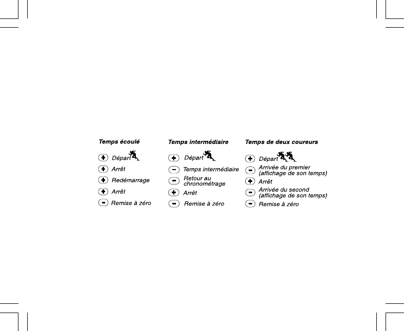
17
Pour mesurer deux temps de course :
1. Appuyez sur le bouton [+] pour démarrer le chronomètre.
2. Appuyez une fois sur le bouton [-] pour arrêter le chronomètre et afficher le temps de course de la première
personne.
3. Appuyez sur le bouton [+] pour arrêter le chronomètre.
4. Appuyez sur le bouton [-] pour afficher le temps de course de la deuxième personne.
5. Appuyez sur le bouton [-] pour remettre le chronomètre à zéro.
Remarque : lorsque le chronomètre est en route, celui-ci continue de défiler en fond même si vous changer de
mode ou de fonction. Le texte « STOP WATCH » clignote dans la zone 3 pour vous indiquer que le chronomètre
est toujours en route.
2.4 FONCTION COMPTE À REBOURS
En mode TIME, appuyez trois fois sur le bouton [Select] pour accéder à cette fonction.
Affichages de la fonction compte à rebours (Fig. 41) :
• La zone 1 affiche les secondes,
• La zone 2 affiche l’heure actuelle, et
• La zone 3 affiche les heures et les minutes et, dans l’angle en bas à droite, le texte « TIMER ».

18
2.4.1 Réglage du compte à rebours
1. Tenez le bouton [Select] enfoncé pendant 2 secondes. Les secondes se mettent à clignoter dans la zone
1.
2. Appuyez sur le bouton [+] pour augmenter les secondes ou sur le bouton [-] pour les diminuer.
3. Une fois les secondes définies, appuyez sur le bouton [Select] pour passer au réglage suivant. Les minutes
se mettent à clignoter à droite dans la zone 3.
4. Appuyez sur le bouton [+] pour augmenter les minutes ou sur le bouton [-] pour les diminuer.
5. Une fois les minutes définies, appuyez sur le bouton [Select] pour passer au réglage suivant. L’heure se
met à clignoter au centre de la zone 3.
6. Appuyez sur le bouton [+] pour augmenter l’heure ou sur le bouton [-] pour la diminuer.
7. Une fois l’heure définie, appuyez sur le bouton [Mode] pour valider les réglages effectués et quitter le mode
paramétrage.
8. Le réglage du compte à rebours est terminé.
2.4.2 Mise en route du compte à rebours
Pour mettre en route le compte à rebours :
1. Dans la fonction compte à rebours, appuyez sur le bouton [+] pour démarrer, arrêter et redémarrer le
compte à rebours.
2. Si vous arrêtez le compte à rebours avant la fin, appuyez sur le bouton [-] pour le réinitialiser.
Remarque : lorsque le compte à rebours est en route, il continue de défiler en fond même si vous changer de
mode ou de fonction. Le texte « TIMER » clignote dans la zone 3 pour vous indiquer que le compte à rebours
est toujours en route.

19
2.5 FONCTION HEURE D'UN DEUXIÈME FUSEAU HORAIRE
(ALTIMAX ET S-LANDER)
Remarque : seuls les ordinateurs de poignet Altimax et S-Lander possèdent cette fonction
En mode TIME, appuyez quatre fois sur le bouton [Select] pour accéder à cette fonction.
Affichages de la fonction heure d'un deuxième fuseau horaire (Fig. 42) :
• La zone 1 affiche " dUA ", ce qui veut dire " dual time " (heure d'un deuxième fuseau horaire),
• La zone 2 affiche l'heure actuelle, et
• La zone 3 affiche l'heure du deuxième fuseau horaire (par ex. l'heure de votre ville d'origine).
Dans cette fonction, vous pouvez afficher les secondes en appuyant sur le bouton [+]. Celles-ci apparaissent
dans la zone 3 pendant 10 secondes. Ensuite, l'affichage revient à l'heure du deuxième fuseau horaire.
2.5.1 Réglage de l'heure d'un deuxième fuseau horaire
Dans la fonction heure d'un deuxième fuseau horaire :
1. Tenez le bouton [Select] enfoncé pendant 2 secondes. Les heures se mettent à clignoter dans la zone 3.
2. Appuyez sur le bouton [+] pour augmenter les heures ou sur le bouton [-] pour les diminuer.
3. Une fois les heures définies, appuyez sur le bouton [Select] pour passer au réglage suivant. Les minutes
se mettent à clignoter, à droite des heures dans la zone 3.
4. Appuyez sur le bouton [+] pour augmenter les minutes ou sur le bouton [-] pour les diminuer.
5. Une fois les minutes définies, appuyez sur le bouton [Mode] pour valider les réglages effectués et quitter le
mode paramétrage.
6. Le réglage de l'heure d'un deuxième fuseau horaire est terminé.
L'heure du deuxième fuseau horaire ne change pas, même si vous changez l'heure principale du mode TIME.
Par exemple, si vous réglez l'heure du deuxième fuseau horaire sur votre ville d'origine, cette heure sera
toujours affichée dans cette fonction même si vous voyagez dans un autre fuseau horaire et que vous changez
l'heure principale en conséquence.
Remarque : la fonction heure d'un deuxième fuseau horaire est entièrement indépendante et n'a aucune
incidence sur les fonctions d'alarme ou de mémoire. Ces dernières dépendent de l'heure locale actuelle.

20
CHAPITRE 3 MODE ALTIMÈTRE (ALTI)
Le mode ALTI possède :
• une unité de mesure réglable (le mètre ou le pied) : de -500 à 9000 mètres ou de -1600 à 29 500 pieds,
• une résolution de 5 m ou 10 ft,
• un affichage de la vitesse d’ascension mis à jour toutes les secondes pendant 3 minutes, puis toutes les
10 secondes (ou moins),
• une mémoire automatique de 24 heures enregistrant toutes les heures l’altitude et la vitesse de montée/
descente, et
• un journal, enregistrant environ 3800 groupes de données (un groupe = altitude, vitesse de montée/descente
et heure).
Pour visualiser et utiliser le mode ALTI :
Consultez l’indicateur de mode. En appuyant sur le bouton [Mode], faites passer la flèche triangulaire sous
l’indication ALTI.
En mode ALTI (Fig. 1) :
• La zone 1 affiche la vitesse de montée/descente,
• La zone 2 affiche l’altitude actuelle par pas de 5 mètres ou 10 pieds (selon l’unité de mesure sélectionnée),
et
• La zone 3 affiche l’heure actuelle.
• L’affichage circulaire indique l’altitude en centaines de mètres (ou pieds) au-delà de mille mètres, où un
tour complet équivaut à 1000.
REMARQUE IMPORTANTE : AFIN DE DÉFINIR L’ALTITUDE EN MODE ALTI, VOUS DEVEZ CONNAÎTRE
L’ALTITUDE. CETTE INFORMATION PEUT ÊTRE TROUVÉE À L’AIDE D’UNE CARTE TOPOGRAPHIQUE,
EN IDENTIFIANT VOTRE EMPLACEMENT ET EN RELEVANT L’ALTITUDE INDIQUÉE POUR CET
EMPLACEMENT. UNE FOIS L’ALTITUDE CONNUE, SUIVEZ LES INSTRUCTIONS DONNÉES À LA SECTION
SUIVANTE POUR RÉGLER L’ALTIMÈTRE. VOUS TROUVEREZ DES INFORMATIONS CONCERNANT LES
EFFETS DE LA TEMPÉRATURE DE L’AIR SUR LES DONNÉES D’ALTITUDE EN PAGE 43 DE CE MANUEL.

21
SI VOUS NE CONNAISSEZ PAS VOTRE ALTITUDE, VOUS POUVEZ DÉFINIR LA PRESSION RÉDUITE AU
NIVEAU DE LA MER EN MODE BARO (VOIR PAGE 31, RÉGLAGE DE LA PRESSION RÉDUITE AU NIVEAU
DE LA MER). EN DÉFINISSANT LA PRESSION RÉDUITE AU NIVEAU DE LA MER, L’ALTIMÈTRE SE RÈGLE
SUR L’ALTITUDE ACTUELLE AVEC UNE PRÉCISION DE PLUS OU MOINS DIX MÈTRES (QUELQUES
CENTAINES DE PIEDS). POUR CONNAÎTRE LA PRESSION RÉDUITE AU NIVEAU DE LA MER ACTUELLE,
CONSULTEZ LES JOURNAUX, LES INFORMATIONS LOCALES, LES BULLETINS MÉTÉO OU INTERNET.
3.1 RÉGLAGE DE L’ALTIMÈTRE
L’altimètre possède trois paramètres :
• l’altitude de référence (altitude connue de votre emplacement actuel),
• l’alarme d’altitude (vous avertit lorsque vous avez atteint une altitude préprogrammée), et
• l’intervalle d’enregistrement du journal (permet de connaître l’altitude et la vitesse de montée à des intervalles
définis).
Pour commencer :
1. Tenez le bouton [Select] enfoncé pendant 2 secondes. Le texte « RE » (pour altitude de référence) apparaît
dans la zone 1, et l’altitude actuelle se met à clignoter dans la zone 2 (Fig. 2).
2. Appuyez sur le bouton [+] pour augmenter l’altitude ou sur le bouton [-] pour la diminuer.
3. Une fois l’altitude de référence définie, appuyez sur le bouton [Mode] pour valider les réglages effectués et
revenir au mode principal ou appuyez sur le bouton [Select] pour passer au réglage suivant. Si vous appuyez
sur le bouton [Select], l’indication « ON » ou « OFF » se met à clignoter dans la zone 1 (Fig. 3).
4. Appuyez sur le bouton [+] ou le bouton [-] pour activer (« ON ») ou désactiver (« OFF ») l’alarme d’altitude.
5. Une fois ce réglage effectué, appuyez sur le bouton [Select] pour passer au réglage suivant. L’altitude de
l’alarme se met à clignoter dans la zone 2.
6. Appuyez sur le bouton [+] pour augmenter l’altitude ou sur le bouton [-] pour la diminuer.
7. Une fois l’altitude définie, appuyez sur le bouton [Mode] pour valider les réglages effectués et revenir au
mode principal ou appuyez sur le bouton [Select] pour passer au réglage suivant. Le texte « INT » apparaît
dans la zone 1 et l’intervalle d’enregistrement se met à clignoter dans la zone 2 (Fig. 4).
8. Appuyez sur le bouton [+] ou le bouton [-] pour augmenter ou diminuer l’intervalle. Vous avez le choix entre
20 secondes, 1 minute, 10 minutes ou 60 minutes.

22
Intervalles recommandés :
Activité Intervalle
Ski 20 s ou 1 min
Vélo 20 s ou 1 min
Randonnée 10 min
Alpinisme 10 min ou 60 min
Remarque : lorsque vous sélectionnez l’intervalle, vous choisissez a) l’intervalle d’enregistrement de l’altitude,
de la vitesse de montée/descente et de l’heure actuelle et b) la durée maximale d’enregistrement du journal.
Plus l’intervalle est court et plus précises seront les informations enregistrées, étant donné que le taux
d’échantillonnage est plus rapide. La durée maximale d’enregistrement des journaux est expliquée en page 25.
9. Une fois l’intervalle défini, appuyez sur le bouton [Mode] pour valider les réglages effectués et quitter le
mode paramétrage.
Une fois que vous avez réglé l’altitude de référence grâce à l’altitude de votre emplacement actuel, votre
ordinateur de poignet ajuste également la pression réduite au niveau de la mer et, par conséquent, vous
n’aurez pas à définir cette valeur ultérieurement.
Remarque : si vous n’appuyez sur aucun bouton avant une minute lorsque vous vous trouvez en mode
paramétrage, celui-ci disparaît.
Remarque : un intervalle de 10 minutes signifie que votre ordinateur de poignet enregistre des données toutes
les 10 minutes.

23
3.2 FONCTION MESURE DE DÉNIVELÉ
En mode ALTI, appuyez une fois sur le bouton [Select] pour accéder à cette fonction.
Affichages de la fonction mesure de dénivelé (Fig. 13) :
• La zone 1 affiche la vitesse de montée/descente,
• La zone 2 affiche l’altitude actuelle par pas de 5 mètres ou 10 pieds (selon l’unité de mesure sélectionnée),
et
• La zone 3 affiche la durée écoulée ; le texte « DIFFER » apparaît à gauche de cette durée.
• L’affichage circulaire indique l’altitude en centaines de mètres (ou pieds) au-delà de mille mètres, où un
tour complet équivaut à 1000.
La durée écoulée s’affiche jusqu’à 39 heures et 59 minutes ; au-delà, trois tirets (-:--) apparaissent dans la
zone 3. Si vous souhaitez que cette fonction reste affichée en continu pendant 12 heures, votre ordinateur de
poignet revient automatiquement au mode TIME.
Cette fonction continue en fond et vous pouvez ainsi changer de mode si vous le désirez, et revenir à tout
moment à cette fonction pour voir l’état en cours.
Remarque : la fonction de mesure de dénivelé est une mesure relative. Tout changement dans l’altitude de
référence pendant la mesure de dénivelé a une incidence sur les données obtenues. Nous vous conseillons
de toujours vérifier l’altitude de référence (et de la redéfinir si nécessaire) avant de commencer une nouvelle
mesure.
3.2.1 Activation de la fonction mesure de dénivelé
1. Tenez le bouton [Select] enfoncé pendant 2 secondes. Le texte « SET » apparaît dans la zone 1 et zéro se
met à clignoter dans la zone 2 (Fig. 14).
2. Appuyez sur le bouton [Mode] pour accepter le zéro clignotant et activer la mesure de dénivelé.
Si vous ne souhaitez pas activer la mesure de dénivelé, appuyez sur le bouton [+] ou le bouton [-] pour passer
à l’altitude actuelle et appuyez sur le bouton [Mode] pour quitter le mode paramétrage.
Remarque : si vous n’appuyez sur aucun bouton avant une minute lorsque vous vous trouvez en mode
paramétrage, l’affichage revient au mode principal sans remettre l’altimètre à zéro.

24
3.3 FONCTION MÉMOIRE 24 HEURES
En mode ALTI, appuyez deux fois sur le bouton [Select] pour accéder à cette fonction.
Affichages de la fonction mémoire 24 heures (Fig. 15) :
• La zone 1 affiche la vitesse de montée/descente,
• La zone 2 affiche l’altitude actuelle par pas de 5 mètres ou 10 pieds (selon l’unité de mesure sélectionnée),
et
• La zone 3 affiche l’heure sélectionnée et, sur la gauche, le texte « MEMORY ».
• L’affichage circulaire indique l’altitude en centaines de mètres (ou pieds) au-delà de mille mètres, où un
tour complet équivaut à 1000.
Pour afficher les informations accumulées dans la mémoire 24 heures:
1. Appuyez sur le bouton [-] pour faire défiler vers le bas les heures enregistrées et afficher la vitesse de
montée/descente et l’altitude pour chaque heure.
2. Appuyez sur le bouton [+] pour faire défiler les heures vers le haut.
Remarque : les informations de la mémoire sont conservées même lorsque vous changez la pile de votre
ordinateur de poignet.
3.4 FONCTION JOURNAL
En mode ALTI, appuyez trois fois sur le bouton [Select] pour accéder à cette fonction. La fonction journal
possède cinq affichages. Ces cinq affichages apparaissent automatiquement en boucle l’un après l’autre. Le
premier reste à l’écran pendant 7 secondes, puis les autres suivent à des intervalles de 4 secondes.
Premier affichage (Fig. 16) :
• La zone 1 affiche l’année,
• La zone 2 affiche le texte « LO », suivi du numéro du journal sélectionné (ce numéro clignote), et
• La zone 3 affiche le mois et le jour du journal sélectionné. Le texte « LOG BOOK » apparaît à gauche du
mois et de la date.
Vous pouvez appuyer sur le bouton [-] pour faire défiler vers le bas et afficher les journaux précédemment

25
enregistrés, et appuyer sur le bouton [+] pour faire défiler vers le haut jusqu’à revenir au journal actuel.
Le deuxième affichage montre les informations de montée du journal sélectionné (Fig. 17).
• La zone 1 affiche la vitesse moyenne de montée au cours de l’activité,
• La zone 2 affiche la montée totale, et
• La zone 3 affiche le texte « ASC » ainsi que le texte « Log Book » sur la gauche.
Le troisième affichage montre les informations de descente du journal sélectionné (Fig. 18).
• La zone 1 affiche la vitesse moyenne de descente au cours de l’activité,
• La zone 2 affiche la descente totale, et
• La zone 3 affiche le texte « dSC » ainsi que le texte « Log Book » sur la gauche.
Le quatrième affichage montre le nombre de courses (une course correspond à une montée ou à une descente)
enregistrées dans le journal sélectionné (Fig. 19).
• La zone 2 affiche le nombre total de montées ou de descentes, et
• La zone 3 affiche le texte « LAP » ainsi que le texte « Log Book » sur la gauche.
Remarque : une course est un déplacement vertical montant ou descendant équivalant à 50 mètres (150
pieds) ou plus.
Le cinquième affichage montre la durée des informations enregistrées pour le journal sélectionné (Fig. 20).
• La zone 2 affiche la durée totale du journal, et
• La zone 3 affiche le texte « dUr » ainsi que le texte « Log Book » sur la gauche.
Remarque : le journal enregistre des données selon l’intervalle d’enregistrement choisi. Une fois la durée
d’enregistrement écoulée, votre ordinateur de poignet vous signale que l’enregistrement du journal est terminé.
Pour définir les intervalles d’enregistrement du journal, reportez-vous à « Réglage de l’altimètre » page 21.
Les durées maximales d’enregistrement Intervalles du journal Durée maximale d’enregistrement
fonctionnent de la façon suivante : 20 secondes 10 heures
1 minute 12 heures
10 minutes 7 jours
60 minutes 10 jours

26
3.4.1 Mise en route et arrêt d’un journal
Pour les modèles Vector et X-Lander :
En mode ALTI ou dans la fonction de mesure de dénivelé, appuyez sur le bouton [+]. Un bip se fait entendre et
le texte « Log Book » clignote dans la zone 3 pour indiquer le début de l’enregistrement.
Remarque : pour les modèles Vector et X-Lander, lorsque le journal est en train d’enregistrer des données,
vous ne pouvez pas voir ces données. Vous pouvez accéder à ces données uniquement lorsque la session
d’enregistrement est terminée. En revanche, les journaux enregistrés précédemment peuvent être consultés
à tout moment.
Pour arrêter l’enregistrement, appuyez sur [+] une seconde fois. Un bip se fait entendre et le texte
« Log Book » disparaît de la zone 3, confirmant l’arrêt de l’enregistrement.
Remarque : pour éviter de mettre en route ou d’arrêter un journal par erreur, avec les modèles Vector ou X-
Lander, il est conseillé de quitter le mode ALTI. Avec ces modèles, si le journal est activé, l’enregistrement
continue même si vous changez de mode.
Pour les modèles Altimax et S-Lander :
l’enregistrement dans le journal commence en appuyant deux fois sur le bouton [+] dans un laps de 2 secondes.
L’enregistrement dans le journal s’arrête en appuyant également deux fois sur le bouton [+] dans un laps de 2
secondes.
Remarque : pour les modèles Altimax et S-Lander, Vector et X-Lander, les journaux s’effacent automatiquement
et vous ne pouvez donc pas les effacer.
Remarque : pour une plus grande précision, commencez des journaux plus souvent ou réduisez l’intervalle
d’enregistrement.
3.4.2 Bouton de cumul rapide
Cette fonction n’existe que pour les modèles Altimax et S-Lander. Elle permet de connaître le nombre de
courses ainsi que la montée/descente cumulée (en pieds ou en mètres) du journal en cours d’enregistrement.
Pour accéder à ces informations, appuyez sur le bouton [-] dans n’importe quel mode principal. Une fois cette
fonction activée, trois affichages apparaissent l’un après l’autre, à des intervalles de quatre secondes.
• Le premier affichage indique la montée cumulée depuis le début de l’enregistrement.

27
• Le deuxième affichage indique la descente cumulée depuis le début de l’enregistrement.
• En enfin, le troisième affichage indique le nombre de courses effectuées depuis le début de l’enregistrement.
Après le troisième affichage, votre ordinateur de poignet revient automatiquement au mode activé avant la
consultation de ces données cumulées.
Remarque : lorsque cette fonction est activée, le bouton [-] permet de passer à l’affichage suivant sans
attendre les quatre secondes.
3.5 FONCTION HISTORIQUE DU JOURNAL
L’historique du journal affiche un résumé de tous les journaux enregistrés.
En mode ALTI, appuyez quatre fois sur le bouton [Select] pour accéder à cette fonction. L’historique du journal
possède cinq affichages.
Premier affichage (Fig. 24) :
• La zone 1 affiche l’année du dernier effacement de l’historique du journal,
• La zone 2 affiche le texte « HIS », et
• La zone 3 affiche le mois et la date du dernier effacement de l’historique du journal. Le texte « Log Book »
apparaît à gauche du mois et de la date.
Appuyez sur [+] pour faire défiler les différents affichages.
Deuxième affichage (Fig. 25) :
• La zone 1 affiche le texte « HI »,
• La zone 2 affiche l’altitude la plus haute enregistrée depuis le dernier effacement du journal, et
• La zone 3 affiche la date à laquelle cette altitude a été atteinte ainsi que le texte « Log Book » sur la
gauche.
Troisième affichage (Fig. 26) :
• La zone 1 affiche le texte « ASC »,
• Les zones 2 et 3 affichent la montée cumulée jusqu’à 8 chiffres depuis le dernier effacement. La zone 2 est
activée lorsque la valeur de montée est supérieure à la valeur à 3 chiffres affichée dans la zone 3.
Quatrième affichage (Fig. 27) :

28
• La zone 1 affiche le texte « dSC »,
• Les zones 2 et 3 affichent la descente cumulée jusqu’à 8 chiffres depuis le dernier effacement. La zone 2
est activée lorsque la valeur de montée est supérieure à la valeur à 3 chiffres affichée dans la zone 3.
3.5.1 Effacement de l’historique du journal
Pour effacer l’historique du journal (Fig. 28) :
1. Dans n’importe quel affichage de l’historique, tenez enfoncé le bouton [Select] pendant 2 secondes. Le
texte « CLR » apparaît dans la zone 1, le texte « HIS » dans la zone 2 et « nO » se met à clignoter dans la
zone 3.
2. Appuyez sur le bouton [+] pour choisir « YES » ou « NO ».
3. Appuyez sur le bouton [Mode] pour confirmer l’option « YES ».
L’historique du journal est effacé et une nouvelle date, à partir de laquelle le cumul des mesures reprend, est
définie.
Remarque : si vous n’appuyez sur aucun bouton avant une minute lorsque vous vous trouvez en mode
paramétrage, celui-ci disparaît.
Nous vous conseillons d’effacer l’historique du journal avant d’effectuer des enregistrements dans le journal.
CHAPITRE 4 MODE BAROMÈTRE (BARO)
Le mode BARO possède :
• une unité de mesure réglable (mbar ou inHg) ; de 300 à 1100 mbar ou de 8,90 à 32,40 inHg,
• une résolution de 1 mbar ou 0,05 inHg,
• une tendance barométrique estimée grâce à des mesures effectuées toutes les heures,
• une mémoire automatique enregistrant sur 4 jours la pression atmosphérique (6 enregistrements lors des
6 dernières heures, et ensuite, 1 enregistrement toutes les 6 heures),
• une compensation de température (la température, dans les limites de température définies, n’a aucune
incidence sur la pression)
• une plage de température allant de -20° à 60°C (ou de -5° à 140°F), et
• une résolution de température de 1°C ou 1°F.

29
Remarque : la chaleur de votre corps a une incidence sur les mesures de températures lorsque vous portez
votre ordinateur de poignet à votre bras. Pour obtenir des mesures précises, enlevez votre ordinateur de
poignet et laissez-le à l’écart de toute source de chaleur au moins 15 minutes avant de lire ses mesures.
Si vous êtes en mode BARO depuis plus de 15 minutes et qu’aucune vitesse de déplacement vertical n’a été
enregistrée, laissez reposer votre ordinateur de poignet pendant une heure pour que la température soit
ajustée. Pour obtenir plus rapidement une température mise à jour, appuyez quatre fois sur le bouton [Mode]
pour quitter le mode BARO et y revenir.
Pour visualiser et utiliser le mode BARO :
Consultez l’indicateur de mode. En appuyant sur le bouton [Mode], faites passer la flèche triangulaire sous
l’indication BARO.
En mode BARO (Fig. 5) :
• La zone 1 affiche la température actuelle.
• La zone 2 affiche la pression atmosphérique absolue actuelle.
• La zone 3 affiche l’heure actuelle.
• L’affichage circulaire indique la pression atmosphérique au-delà de 100 millibars ou 1 inHg où un tour
complet équivaut à 100 mbar/1 inHg, selon l’unité de mesure sélectionnée.
Remarque : la pression absolue correspond à la pression réelle de n’importe quel lieu à n’importe quel moment,
alors que la pression réduite au niveau de la mer se réfère à la pression correspondante au niveau de la mer.
4.1 FONCTION MESURE DE DIFFÉRENCE DE PRESSION
La différence de pression ne se réfère pas à la pression réduite au niveau de la mer mais à la pression
barométrique actuelle mesurée par votre ordinateur de poignet.
En mode BARO, appuyez une fois sur le bouton [Select] pour accéder à cette fonction.
Affichages de la fonction mesure de différence de pression (Fig. 30) :
• La zone 1 affiche le changement de température.
• La zone 2 affiche le changement de pression atmosphérique absolue.

30
• La zone 3 affiche l’heure actuelle, à droite du texte « DIFFER ».
• L’affichage circulaire indique le changement de pression (un cercle entier correspond à 100 mbar ou
1 inHg).
Cette fonction reste activée en fond ; vous pouvez donc changer de mode et revenir à tout moment à cette
fonction pour connaître les mesures en cours.
4.1.1 Activation de la fonction mesure de différence de pression
1. Tenez le bouton [Select] enfoncé pendant 2 secondes. Le texte « SET » apparaît dans la zone 1 et zéro se
met à clignoter dans la zone 2 (Fig. 29).
2. Appuyez sur le bouton [Mode] pour accepter le zéro clignotant et activer la mesure de différence de pression.
Si vous ne souhaitez pas activer la mesure de différence de pression, appuyez sur le bouton [+] ou le bouton
[-] pour passer à la mesure de différence de pression barométrique actuelle et appuyez sur le bouton [Mode]
pour quitter le mode paramétrage.
Remarque : si vous n’appuyez sur aucun bouton avant une minute lorsque vous vous trouvez en mode
paramétrage, celui-ci disparaît.
4.2 FONCTION MÉMOIRE 4 JOURS
En mode BARO, appuyez deux fois sur le bouton [Select] pour accéder à cette fonction. Cette fonction permet
de suivre les variations de pression afin de prévoir les changements de conditions météo (par ex. pour prévoir
les tempêtes).
Affichages de la fonction mémoire 4 jours (Fig. 31) :
• La zone 1 affiche le jour de la semaine,
• La zone 2 affiche la pression atmosphérique, et
• La zone 3 affiche l’heure d’enregistrement, à droite du texte « MEMORY ».
• L’affichage circulaire indique la pression atmosphérique (un cercle entier correspond à 100 mbar ou
1 inHg).
Pour afficher les informations accumulées dans la mémoire 4 jours :

31
Appuyez sur le bouton [-] pour faire défiler vers le bas les entrées de la mémoire (un enregistrement par heure
lors des 6 premières heures, et ensuite un enregistrement par intervalles de 6 heures).
Appuyez sur le bouton [+] pour faire défiler les entrées vers le haut.
Remarque : les informations de cette mémoire sont conservées même lorsque vous changez la pile de votre
ordinateur de poignet.
4.3 FONCTION PRESSION RÉDUITE AU NIVEAU DE LA
MER
La pression réduite au niveau de la mer correspond à la pression par rapport au niveau de la mer alors que la
pression donnée par l’affichage du baromètre correspond à la pression absolue de l’emplacement où vous
êtes.
En mode BARO, appuyez trois fois sur le bouton [Select] pour accéder à cette fonction.
Affichages de la fonction de pression réduite au niveau de la mer (Fig. 32) :
• La zone 1 affiche le texte « SEA »,
• La zone 2 affiche la pression réduite au niveau de la mer actuelle, et
• La zone 3 affiche l’heure actuelle.
4.3.1 Réglage de la pression réduite au niveau de la mer
Ce réglage permet également de définir l’altitude de l’ordinateur de poignet lorsque l’altitude de référence
n’est pas connue.
Pour régler la pression réduite au niveau de la mer :
1. Tenez le bouton [Select] enfoncé pendant 2 secondes. La pression réduite au niveau de la mer actuelle se
met à clignoter dans la zone 2.
2. Appuyez sur le bouton [+] pour augmenter la pression ou
appuyez sur le bouton [-] pour la diminuer.
3. Une fois la pression définie, appuyez sur le bouton [Mode] pour valider les réglages effectués et revenir au
mode principal.

32
Une fois cette pression définie, l’altitude de l’ordinateur de poignet s’ajuste automatiquement avec une précision
de plus ou moins dix mètres (quelques centaines de pieds).
Remarque : pour connaître la pression réduite au niveau de la mer actuelle, consultez les journaux, les
informations locales, les bulletins météo ou Internet. Si vous n’appuyez sur aucun bouton avant une minute
lorsque vous vous trouvez en mode paramétrage, celui-ci disparaît.
4.4 INDICATEUR DE TENDANCE BAROMÉTRIQUE
L’indicateur de tendance barométrique se trouve dans l’angle en haut à gauche de l’écran LCD. Il reste affiché
en permanence dans tous les modes, permettant ainsi d’analyser d’un simple coup d’œil les conditions
météo à venir.
La tendance barométrique est représentée par deux segments formant une flèche. Chaque segment représente
une période de 3 heures. Le segment de droite représente les 3 dernières heures. Le segment de gauche
représente les 3 heures précédant les 3 dernières heures. Ces deux segments peuvent former 9 flèches
différentes :
Situation il y a 3 à 6 heures Situation des 3 dernières heures
Forte chute de pression (>2 mbar/3heures) Forte chute de pression (>2 mbar/3heures)
Forte chute de pression (>2 mbar/3heures) La situation se stabilise
Forte chute de pression (>2 mbar/3heures) Forte augmentation de pression (>2 mbar/3heures)
La situation était stable Forte chute de pression (>2 mbar/3heures)
La situation était stable La situation reste stable
La situation était stable Forte augmentation de pression (>2 mbar/3heures)
Forte augmentation de pression (>2 mbar/3heures) Forte augmentation de pression (>2 mbar/3heures)
Forte augmentation de pression (>2 mbar/3heures) La situation reste stable
Forte augmentation de pression (>2 mbar/3heures) Forte chute de pression (>2 mbar/3heures)
Remarque : si vous restez à la même altitude, l’indicateur de tendance barométrique permet de prévoir la
météo.

33
CHAPITRE 5 MODE BOUSSOLE (COMP) (VECTOR ET X-
LANDER)
Remarque : ce mode ne concerne que les modèles Vector et X-Lander.
Le mode COMP possède :
• une abréviation des points cardinaux et semi-cardinaux,
• des degrés,
• une flèche Nord-Sud,
• une fonction suivi de cap affichant le cap à suivre et la direction actuelle,
• un niveau à bulle avec une précision de +3 degrés (uniquement sur le modèle Vector),
• une couronne rotative,
• une résolution de 1° pour le cap à suivre et de +5° pour la direction Nord-Sud, et
• une fonction de correction de déclinaison.
Pour visualiser et utiliser le mode COMP :
Consultez l’indicateur de mode. En appuyant sur le bouton [Mode], faites passer la flèche triangulaire sous
l’indication COMP.
En mode COMP (Fig. 6) :
• La zone 1 affiche le point cardinal ou semi-cardinal.
• La zone 2 affiche le cap à suivre en degrés.
• La zone 3 affiche l’heure actuelle.
• L’affichage circulaire indique la flèche Nord-Sud, où un segment allumé représente le Nord et trois segments
allumés représentent le Sud.
Votre ordinateur de poignet possède un niveau à bulle pour que vous puissiez faire des mesures précises (+/
- 3 degrés). Pour obtenir un cap, retirez votre ordinateur de poignet. À l’aide du niveau à bulle, assurez-vous
que votre ordinateur de poignet est à plat (bulle au centre du niveau) et effectuez les mesures.

34
L’affichage de la boussole reste actif pendant 45 secondes. Au bout de 45 secondes, la boussole passe en
mode veille et l’indicateur « ---° » apparaît dans la zone 2. Réactivez la boussole en appuyant sur le bouton [-].
Remarque : pour effectuer des mesures à l’aide de la boussole, éloignez-vous des sources magnétiques.
Évitez les bâtiments, les objets métalliques de grande taille, les lignes électriques, les haut-parleurs, les
moteurs électriques, etc.
Prenez toujours vos mesures en plein air, et non à l’intérieur de tentes, de grottes ou autres abris.
5.1 FONCTION SUIVI DE CAP
Vous pouvez passer de l’affichage des points cardinaux au mode suivi de cap et utiliser la fonction de verrouillage
du cap à suivre pour vous orienter (Fig. 7).
En mode COMP :
1. Tenez le bouton [Select] enfoncé pendant 2 secondes. « OFF » se met à clignoter dans la zone 1 (Fig. 8).
2. Appuyez sur le bouton [+] ou le bouton [-] pour choisir entre « ON » et « OFF ».
3. Une fois ce paramètre défini, appuyez sur le bouton [Select] pour passer au réglage suivant. Le cap actuel
en degré se met à clignoter dans la zone 2 (Fig. 9).
4. Orientez votre ordinateur de poignet dans la direction désirée. Verrouillez le cap à suivre qui s’affiche en
appuyant sur le bouton [-].
5. Ajustez le cap ainsi verrouillé, si nécessaire, en appuyant sur le bouton [Select] et ensuite en ajustant la
valeur avec les boutons [+] et [-].
6. Une fois le cap à suivre défini, appuyez sur le bouton [Mode] pour valider les réglages effectués et quitter
le mode paramétrage.
Remarque : si vous n’appuyez sur aucun bouton avant une minute lorsque vous vous trouvez en mode
paramétrage, celui-ci disparaît.
Remarque : le verrouillage du cap à suivre vous empêche de lire la boussole.

35
5.2 FONCTION CORRECTION DE DÉCLINAISON
Votre ordinateur de poignet permet de compenser la différence entre le Nord géographique et le Nord
magnétique.
Ainsi, en ajustant la déclination, vous pouvez obtenir des mesures correctes.
En mode COMP, appuyez une fois sur le bouton [Select] pour accéder à cette fonction.
Affichages de la fonction correction de déclinaison (Fig. 33) :
• La zone 1 affiche le sens de la déclinaison « OFF », où « OFF » = aucune déclinaison, W = ouest et E =
est.
• La zone 2 affiche la déclinaison en degrés.
• La zone 3 affiche le texte « dEC ».
5.2.1 Réglage de la déclinaison locale
1. Tenez le bouton [Select] enfoncé pendant 2 secondes. « OFF » se met à clignoter dans la zone 1.
2. Appuyez sur le bouton [+] ou le bouton [-] pour changer le sens de la déclinaison.
3. Une fois le sens défini, appuyez sur le bouton [Select] pour passer au réglage suivant. Les degrés se
mettent à clignoter dans la zone 2.
4. Appuyez sur le bouton [+] pour augmenter les degrés ou sur le bouton [-] pour les diminuer.
5. Une fois les degrés définis, appuyez sur le bouton [Mode] pour valider les réglages effectués et quitter le
mode paramétrage.
Remarque : si vous n’appuyez sur aucun bouton avant une minute lorsque vous vous trouvez en mode
paramétrage, celui-ci disparaît.
Le réglage de la déclinaison locale est terminé.

36
5.3 ÉTALONNAGE DE LA BOUSSOLE
L’étalonnage de la boussole est nécessaire si votre ordinateur de poignet est entré en contact avec des
sources magnétiques, s’il a subi des températures extrêmement froides, si vous avez changé sa pile ou si
vous pensez que des conditions environnementales ont peut-être affecté le fonctionnement de la boussole.
Remarque : nous vous conseillons d’étalonner la boussole avant de l’utiliser pour la première fois et également
à chaque fois que vous partez pour une randonnée au cours de laquelle vous utiliserez la boussole.
Pour commencer l’étalonnage :
1. En mode COMP, appuyez deux fois sur le bouton [Select]. Le texte « CMP » apparaît dans la zone 1. Le
texte « CAL » apparaît dans la zone 3 (Fig. 34).
2. Tenez le bouton [Select] enfoncé pendant 2 secondes. Le texte « PUSH » se met à clignoter dans la zone
2 (Fig. 35).
3. Appuyez sur le bouton [-] pour lancer l’étalonnage.
4. « 360° » apparaît dans la zone 2 et l’affichage circulaire allume tous ses segments (Fig. 36). Une fois les
segments allumés, tenez votre ordinateur de poignet à plat et faites-le pivoter lentement pour lui faire faire
un tour. Le sens de rotation importe peu. Au fur et à mesure que vous tournez, les segments s’éteignent.
Une fois que vous avez effectué un tour complet, l’instrument vous informe dans la minute qui suit si
l’étalonnage a réussi (le texte « dOnE » s’affiche dans la zone 2 (Fig. 37)) ou s’il l’opération doit être
répétée (« PUSH » et « - » s’affichent dans la zone 2).
Remarque : pour réussir l’étalonnage, il se peut que vous deviez tourner la boussole plus de deux fois.
Remarque : au cours de l’étalonnage, il n’est pas nécessaire que tous les segments périphériques s’allument
ou s’éteignent.
Remarque : si le texte « FAIL » apparaît dans la zone 2 (Fig. 38), retirez la pile et remettez-la avant de procéder
à l’étalonnage de la boussole. Cette opération réinitialise votre ordinateur de poignet.
5. Une fois l’étalonnage réussi, appuyez sur le bouton [Mode] pour valider l’opération et quitter le mode
étalonnage.
Remarque : pour un étalonnage plus précis, n’oubliez pas de tenir votre ordinateur de poignet à plat pendant
l’opération.
L’étalonnage de la boussole est terminé.

37
CHAPITRE 6 FOIRE AUX QUESTIONS
6.1 GÉNÉRALITÉS
6.1.1 Mon ordinateur de poignet est-il étanche ?
Oui, il est étanche jusqu’à une profondeur de 30 mètres (100 ft). La pluie et autres projections d’eau n’affectent
pas son fonctionnement. Vous pouvez également porter votre ordinateur de poignet pour nager. Cependant,
votre ordinateur de poignet N’EST PAS un instrument de plongée.
6.1.2 Combien de temps la pile dure-t-elle ?
La durée de la pile dépend de la façon dont vous utilisez votre ordinateur de poignet. La durée de vie de la pile
dépend principalement de l’utilisation du rétro-éclairage, de la boussole et du journal. Le symbole de niveau
de pile faible apparaît sur l’affichage lorsque la pile atteint 5-15 % de sa capacité maximale. Lorsque ce
symbole s’affiche, vous avez largement le temps de changer la pile en toute sécurité.
6.1.3 Que représentent les segments de l’affichage circulaire ?
En mode ALTI, un cercle entier équivaut à 1000 mètres ou 1000 pieds. Par conséquent, les segments de
l’affichage circulaire indiquent l’altitude au-delà de mille. Lorsque vous utilisez la fonction mesure de dénivelé
de l’altimètre, les segments indiquent le dénivelé au-delà de mille, soit vers la droite si vous montez, soit vers
la gauche si vous descendez.
En mode BARO, un cercle entier équivaut à 100 mbar ou 1 inHg, et les segments indiquent la pression au-
delà de cent mbar ou un inHg. Lorsque vous utilisez la fonction mesure de différence de pression du baromètre,
les segments indiquent les changements de pression atmosphérique soit vers la droite en cas d’augmentation
de pression, soit vers la gauche en cas de chute de pression.
En mode COMP, les segments indiquent le Nord : le segment unique indique le Nord et les trois segments
pointent vers le Sud. Si vous utilisez la fonction suivi de cap de la boussole, les segments de l’affichage
circulaire indiquent la différence entre le cap que vous souhaitez suivre et votre direction actuelle.

38
6.1.4 Pourquoi les segments de l’affichage circulaire vont-ils vers
la gauche (sens inverse des aiguilles d’une montre) ?
Normalement, les segments vont vers la droite (sens des aiguilles d’une montre) à partir du repère midi/
minuit.
Dans le cas contraire, c’est que vous avez activé une fonction mesurant des différences de valeurs (pression
ou dénivelé). En mode normal, les segments apparaissent dans le sens des aiguilles d’une montre, mais si
vous activez une fonction indiquant des différences (tel le dénivelé), toutes les valeurs descendantes
apparaissent vers la gauche et les valeurs montantes vont vers la droite. En quelque sorte, les valeurs
« négatives » sont indiquées vers la gauche et les valeurs « positives » vers la droite.
6.1.5 Pourquoi y a-t-il deux symboles au-dessus de l’indicateur de
mode et que signifient-ils ?
Le symbole de gauche indique que l’alarme d’altitude est activée et le symbole de droite indique que une,
deux ou trois alarmes journalières sont activées.
6.2 MONTRE
6.2.1 Pourquoi les segments de l’affichage circulaire augmentent
et diminuent lorsque le mode TIME est activé ?
Les segments servent principalement au mode COMP, où une division d’un cercle en 36 segments est
nécessaire (du fait des 360 degrés de l’échelle d’une boussole). En mode TIME, les segments indiquent la
progression des secondes. Étant donnée que le nombre de secondes diffère du nombre de degrés, il est
impossible pour les segments de s’allumer les uns après les autres ; ils s’allument et s’éteignent de sorte à
représenter le passage de chaque seconde.
6.2.2 Quelle est la durée maximale du compte à rebours ?
Vous pouvez régler le compte à rebours jusqu’à 23 heures 59 minutes et 59 secondes au maximum.

39
6.3 ALTIMÈTRE
6.3.1 Comment puis-je effacer le journal ?
Le journal s’efface automatiquement de lui-même et vous ne pouvez donc pas l’effacer vous-même.
6.3.2 Comment le journal s’efface-t-il de lui-même ?
La mémoire du journal est circulaire, c’est à dire qu’elle commence à s’effacer lorsque tous les emplacements
de la mémoire sont occupés. La mémoire contient environ 3800 emplacements, chacun contenant votre
altitude et votre vitesse de montée/descente à l’heure d’enregistrement (selon l’intervalle d’enregistrement
choisi : 20 secondes, 1 minute, 10 ou 60 minutes).
Lorsque tous les emplacements de la mémoire sont occupés, le journal enregistre les nouvelles données en
écrasant les plus anciennes.
Ainsi, les entrées du journal sont effacées automatiquement, sans aucune intervention de votre part.
En revanche, vous pouvez effacer l’historique du journal, qui contient les informations cumulées de montée et
de descente en fonction des données enregistrées dans le journal.
6.3.3 Combien de journaux puis-je enregistrer ?
Le nombre d’entrées que vous pouvez enregistrer dépend de l’intervalle d’enregistrement choisi et de la durée
de chaque journal.
Par exemple, si vous choisissez un intervalle de 1 minute, vous pouvez enregistrer 3800 minutes d’entrées
dans le journal. 3800 minutes correspondent à 2,64 jours d’enregistrement continu (24 heures = 1440 minutes;
3800/1440=2,64).
Pour éviter d’user trop la batterie, l’enregistrement dans le journal ne devrait pas être continu. Certaines
fonctions disposent d’une durée maximale d’enregistrement (c’est à dire que l’enregistrement s’arrête
automatiquement au bout d’un certain temps). Ces durées sont plus courtes si les intervalles d’enregistrement
sont plus rapprochés et plus longues avec des intervalles plus espacés.
6.3.4 Qu’est-ce que l’affichage de la durée ?
L’affichage de la durée vous indique le nombre d’heures et/ou de minutes de l’activité enregistrée dans le

40
journal. Par exemple, pour une randonnée de 13h00 à 18h00, avec le journal activé, l’affichage indique une
durée de 05:00 heures.
6.3.5 Quelle est la capacité maximale de montée/descente totale
(en mètres ou en pieds) que l’historique du journal peut
enregistrer ?
Le nombre maximum pouvant apparaître sur l’affichage est 29 999,999, qu’il s’agisse de pieds ou de mètres.
Cette valeur devrait suffire pour la plupart des utilisateurs : en effet, 29 999,999 mètres représentent plus ou
moins trois quarts de la circonférence de la Terre.
6.3.6 Si, lors d’une randonnée, je passe de 1600 m à 1000 m et
qu’ensuite je remonte à 2800 m, comment mon ordinateur de
poignet interprète-t-il ces déplacements ?
Cette question implique plusieurs réponses en fonction du contexte.
Premièrement, si vous souhaitez savoir si votre ordinateur de poignet est capable d’indiquer avec précision
les informations d’altitude suite à des descentes et à des montées successives, la réponse est oui, à condition
que les changements de condition météo n’aient pas modifié la pression barométrique. Puisque l’altitude est
indiquée par rapport à la pression atmosphérique, l’altitude peut être modifiée suite à des variations de pression.
Mais si les conditions restent inchangées, et que l’altitude de référence est définie, votre ordinateur de poignet
vous fournira des mesures précises.
Deuxièmement, si vous vous interrogez sur la façon dont votre ordinateur de poignet calcule les informations
indiquées dans le journal, voici quelques explications : en ce qui concerne l’ascension totale enregistrée dans
le journal (si vous avez activé cette fonction dès votre départ bien sûr), il calcule la montée de 1000 à 2800 m,
c’est à dire une montée totale de 1800 m. La descente, quant à elle, est calculée de 1600 à 1000 m, soit une
descente totale de 600 m.
Troisièmement, si vous pensez à la fonction de mesure de dénivelé (toujours en considérant notre contexte
d’exemple), votre ordinateur de poignet indique le dénivelé positif entre 1600 m et 2800 m (début et fin). Le fait
que vous soyez descendu à 1000 m au cours de votre randonnée n’a aucun impact sur le dénivelé absolu
entre votre point de départ et votre arrivée.

41
Enfin, la mémoire automatique 24 heures affiche les informations de la façon suivante : disons que vous
commencez à 1600 m à midi, qu’il vous faut deux heures pour descendre à 1000 m, puis cinq heures pour
atteindre 2800 m. Les affichages de la mémoire indiquent votre altitude heure par heure, et défilent de la façon
suivante : 1600 m à 12h00, puis 1400 m à 13h00, 1000 m à 14h00, 1300 m à 15h00, 2000 m à 16h00,
2200 m à 17h00, 2600 m à 18h00 et enfin 2800 m à 19h00.
Comme vous l’avez vu, votre ordinateur de poignet vous renseigne de différentes façons selon le contexte.
Le plus important étant de TOUJOURS définir une altitude de référence connue dans votre ordinateur de
poignet. Les mesures d’altitude seront ainsi plus précises.
6.3.7 Pourquoi les mesures de montée/descente sont-elles
différentes même si je reste à l’intérieur d’une même pièce ?
La résolution de la vitesse de montée/descente est de 1 m/1 ft alors que la résolution de l’affichage de
l’altitude est de 5 m/10 ft, ce qui signifie que la vitesse de montée/descente peut indiquer des déplacements
verticaux même si vous restez à la même altitude. Ces différences sont dues à des variations de pression ou
même à des déplacements verticaux au sein de la plage de résolution de 5 m/10 ft.
En intérieur, même des courants d’air que l’on ne peut ressentir peuvent entraîner des variations de pression.
Par exemple, si vous laissez une fenêtre ouverte dans une pièce de votre maison, la pression atmosphérique
de cette pièce peut changer sans que vous le remarquiez, alors que les capteurs de votre ordinateur de
poignet le peuvent. Étant donné que votre ordinateur de poignet mesure les montées et les descentes par
rapport aux variations de pression atmosphérique, il interprète ces changements comme des déplacements
verticaux.
6.4 BAROMÈTRE
6.4.1 Que représente la petite case en haut à gauche de l’écran ?
Il s’agit de l’indicateur de tendance barométrique, qui affiche la tendance générale des changements météo.
Cet affichage repose sur les mesures du baromètre lors des 6 dernières heures.

42
6.4.2 Mon ordinateur de poignet peut-il afficher les tendances
météo à venir ?
Non. Votre ordinateur de poignet recueille en continu les données de pression barométrique des 6 dernières
heures et affiche des tendances barométriques générales en fonction des données recueillies.
6.4.3 Que signifient « pression absolue » et « pression relative » ?
La pression absolue correspond à la pression réelle de n’importe quel lieu à n’importe quel moment. La
pression relative, quant à elle, se réfère à la pression correspondante au niveau de la mer en fonction de
l’altitude à laquelle vous êtes. Par exemple, si vous êtes à une altitude de 1000 m/3300 ft, la pression absolue
se trouve normalement autour de 900 mbar/26,60 inHg. La pression relative au niveau de la mer est d’environ
1013 mbar/29,90 inHg.
6.4.4 Qu’est-ce que la compensation de température ?
Un instrument à compensation de température signifie que la température de cet instrument n’a aucun influence
sur l’altitude qu’il mesure. L’instrument peut être porté au poignet ou posé sur une table, il vous donnera dans
les deux cas des mesures d’altitude correctes (à condition bien sûr que les conditions météo ne changent
pas). Tous les ordinateurs de poignet Suunto sont à compensation de température dans une limite de -20 à
+60°C / -5 à 140°F.
6.5 BOUSSOLE
6.5.1 Quel est le rôle de la couronne rotative ?
La couronne rotative vous permet d’utiliser votre ordinateur de poignet comme une boussole traditionnelle, en
utilisant la couronne pour, par exemple, indiquer le Nord en mode suivi de cap et pouvoir changer d’affichage
à tout moment.
De plus, cette couronne permet de suivre manuellement vos déplacements verticaux en utilisant l’indicateur
du Nord de la couronne pour repérer l’altitude à partir de laquelle vous souhaitez suivre votre progression
(comme un point de départ). Vous pouvez également repérer une altitude particulière, indiquée par les segments
de l’affichage circulaire, pour obtenir un dénivelé intermédiaire. Cela dit, la couronne est principalement liée
aux fonctions de la boussole.

43
6.5.2 Où puis-je trouver la déclinaison de mon emplacement pour
la définir dans mon ordinateur de poignet ?
La déclinaison locale, soit E ou O, apparaît généralement sur les cartes avec une précision de 1 ou de
0,5 degrés.
6.6 EFFET DE LA TEMPÉRATURE DE L’AIR SUR LES
MESURES D’ALTITUDE
La pression atmosphérique correspond au poids de l’air à la surface de la Terre : à une altitude plus élevée, il
y a moins d’air qu’à une altitude plus faible. Le principe d’un altimètre est de mesurer les différentes pressions
atmosphériques à différentes altitudes.
La température extérieure influe sur le poids de l’air. En conséquence, la différence de pression atmosphérique
entre deux altitudes dépend également de la température.
Votre ordinateur de poignet calcule l’altitude en fonction de la pression atmosphérique à des températures de
référence définies. Chaque altitude est associée à une température de référence fixe. Les températures de
référence de chaque altitude sont indiquées dans le tableau 1.
Altitude (m) Altitude (ft) Température (C) Température (F)
au-dessus du au-dessus du
niveau de la mer niveau de la mer
0 0 15.0 59.0
200 656 13.7 56.7
400 1312 12.4 54.3
600 1969 11.1 52.0
800 2625 9.8 49.6
1000 3281 8.5 47.3
1200 3937 7.2 45.0
1400 4593 5.9 42.6
1600 5250 4.6 40.3

44
1800 5906 3.3 37.9
2000 6562 2.0 35.6
2400 7874 -0.6 30.9
2800 9187 -3.2 26.2
3000 9843 -4.5 23.9
3400 11155 -7.1 19.2
3800 12468 -9.7 14.5
4000 13124 -11.0 12.2
4500 14765 -14.3 6.4
5000 16405 -17.5 0.5
5500 18046 -20.8 -5.4
6000 19686 -24.0 -11.2
Table 1. Températures de référence par rapport à différentes altitudes
Les erreurs de calcul d’altitude causées par une variation de température anormale sont plus ou moins les
suivantes : si la somme des écarts de température par rapport aux températures de référence définies à deux
altitudes différentes est 1ºC, la différence d’altitude calculée par votre ordinateur de poignet est de 0,2 % par
rapport à la différence d’altitude réelle (avec les unités britanniques, la différence est de 0,11 % / 1ºF). Ces
écarts s’expliquent par le fait que les températures réelles ne sont pas toujours les mêmes que les températures
de référence. Une température supérieure à la température de référence fait que la différence d’altitude calculée
est plus basse que la différence d’altitude réelle (votre ascension en montagne est en fait plus importante que
celle affichée).
Ainsi, une température inférieure à la température de référence fait que la différence d’altitude calculée est
plus grande que la différence d’altitude réelle (votre montée n’a pas été aussi importante que celle affichée).
L’exemple illustré dans le tableau 2 présente des écarts de température positifs. Dans cet exemple, l’altitude
de référence est définie sur 1000 m. À 3000 m, la différence d’altitude est de 2000 m mais l’ordinateur de
poignet indique 80 m en moins (20ºC * 2000 m * 0,002/ºC = 80 m). Votre altitude réelle est donc 3080 m.

45
Point le plus bas Point le plus haut
Altitude de référence définie (altitude réelle) 1000 m
Altitude affichée 3000 m
Température extérieure réelle +17,5ºC +6,5ºC
Température de référence (dans tableau) +8,5ºC -4,5ºC
Écart de température (= Temp. réelle - Temp. de référence) +9ºC +11ºC
Somme des écarts de température +9ºC + +11ºC = 20ºC
Tableau 2. Exemple (en mètre et Celsius)
L’exemple illustré dans le tableau 3 présente des écarts de température négatifs. Cette fois-ci, l’exemple est
donné en unités britanniques.
L’altitude de référence est définie sur 3280 pieds. À 9840 pieds, la différence d’altitude est de 6560 pieds mais
l’ordinateur de poignet affiche 100 pieds en plus (-14ºF * 6560 ft * 0,0011/ºF = -100 ft). Votre altitude réelle est
donc 9740 ft.
Point le plus bas Point le plus haut
Altitude de référence définie (altitude réelle) 3280 ft
Altitude affichée 9840 ft
Température extérieure réelle +36,3ºF +18,9ºF
Température de référence (dans tableau) +47,3ºF +23,9ºF
Écart de température (= Temp. réelle - Temp. de référence) -9ºF -5ºF
Somme des écarts de température -9ºF + -5ºF = -14ºF
Tableau 3. Exemple (en pieds et Fahrenheit)
CHAPITRE 7 PIÈCES DÉTACHÉES
Kit de changement de pile (comprenant une pile, un couvercle de logement de pile et un joint)
Bracelets de montre en plastique (Vector/Altimax) ou en cuir, velcro et tissu (S-Lander/X-Lander)
Rallonge de bracelet en plastique
Couronne (fournie uniquement par Suunto Oy lors de l’entretien)

46
Suunto Oy propose à ses clients un service d’entretien à prix modéré de tous ses ordinateurs de poignet.
Les piles sont généralement vendues chez les horlogers, dans les magasins de sport, etc.
CHAPTER 8 ABRÉVIATIONS UTILISÉES SUR L’ÉCRAN LCD
CHAPITRE 9 DROITS D’AUTEUR ET DE PROPRIÉTÉ
INDUSTRIELLE
Cette publication et son contenu sont la propriété de Suunto Oy et sont fournis uniquement pour permettre aux
clients de mieux connaître les caractéristiques et le fonctionnement de ordinateur de poignet Suunto Altimax/
Vector/X-Lander/S-Lander.
Il est interdit d’utiliser ou de diffuser ce contenu pour d’autres fins, et de le communiquer, de le divulguer ou de
le reproduire sans le consentement préalable écrit de Suunto Oy.
Suunto, Wristop Computer, Altimax, Vector, X-Lander, S-Lander et leurs logos sont des marques déposées ou
non de Suunto. Tous droits réservés.
Si les informations contenues dans cette documentation sont à la fois exhaustive et exactes, nous ne donnons
aucune garantie implicite ou explicite quant à leur exactitude.
dEF – configuration d’origine du capteur de pression ;
correspond à une pression atmosphérique au
niveau de la mer standard (1013 mbar ou
29,90 inHg)
SNR – capteur (utilisé lors de l’étalonnage du capteur)
RE – altitude de référence
CLR – effacer
ASC – montée
dSC – descente
bEG – début
bEG – début
HIS – historique
dUA – heure du deuxième fuseau horaire
dUR – durée
CMP – boussole
CAL – étalonnage
bEA – azimut
CHAPTER 10 CONFORMITÉ CE
Tous les ordinateurs de poignet Suunto sont conformes aux exigences la directive européenne sur la compatibilité
électromagnétique 89/336/CEE.

47
CHAPTER 11 LIMITES DE RESPONSABILITÉ ET
CONFORMITÉ ISO 9001
En cas de panne du produit en raison d’un défaut de fabrication ou de matières premières, Suunto Oy procédera
gracieusement à sa réparation ou son remplacement, au choix exclusif de Suunto Oy, à l’aide de pièces
neuves ou réparées, cela pendant deux (2) ans à compter de sa date d’achat. Cette garantie n’est proposée
qu’à l’acheteur initial et ne concerne que les pannes provoquées par les défectuosités des matières et de la
fabrication et intervenant lors d’une utilisation normale pendant la période de garantie.
Cette garantie ne couvre ni les défaillances ou les pannes dues aux accidents, à la mauvaise utilisation, à la
négligence, à la mauvaise manipulation ou aux modifications du produit, ni les défaillances provoquées par
une utilisation non conforme ou par une cause non couverte par cette garantie.
Le fabricant ne donne aucune garantie expresse autre que celles énumérées ci-dessus.
Pour exercer son droit de faire réparer l’appareil sous garantie, l’utilisateur doit contacter notre service Clients
et obtenir une autorisation de réparation.
Suunto Oy, Suunto Europe et Suunto USA/Canada ne sauront en aucun cas être responsables des dommages
accessoires ou indirects dus à l’utilisation ou à l’impossibilité d’utiliser ce produit. Suunto Oy décline toute
responsabilité en cas de recours de tiers suite à un sinistre consécutif à l’utilisation de cet appareil.
Le système d’assurance qualité de Suunto est certifié conforme à la norme ISO 9001 pour toutes les activités
de Suunto Oy par Det Norske Veritas (certificat qualité n° 96-HEL-AQ-220).
CHAPTER 12 COMMENT SE DÉBARRASSER
DE VOTRE INSTRUMENT
Pour vous débarrasser de cet instrument, veuillez respecter les normes en vigueur relatives
aux déchets électroniques. Ne le jetez pas avec les ordures ménagères. Rapportez-le à
votre représentant Suunto le plus proche.

48

1
BEDIENUNGSANLEITUNG
KUNDENDIENSTE
Suunto Oy Tel. +358 9 875870
Fax +358 9 87587301
Suunto USA Tel. 1 (800) 543-9124
Canada Tel. 1 (800) 776-7770
Europaweites Call Center Tel. +358 2 284 11 60
Suunto im Internet www.suunto.com
DE

2
INHALTSVERZEICHNIS
KAPITEL 1 EINFÜHRUNG ................................................................ 6
1.1 ALLGEMEINE INFORMATIONEN ................................................................................ 6
1.2 HAUPTFUNKTIONEN (MODI) ..................................................................................... 6
1.2.1 Hintergrundbeleuchtung ................................................................................ 7
1.2.2 Wasserdichtigkeit .......................................................................................... 7
1.3 TASTENFUNKTIONEN ................................................................................................ 7
1.3.1 Die Taste [Mode]............................................................................................ 7
1.3.2 Die Taste [+] .................................................................................................. 8
1.3.3 Die Taste [-] ................................................................................................... 8
1.3.4 Die Taste [Select] .......................................................................................... 8
1.4 LCD-DISPLAY .............................................................................................................. 8
1.5 MASSE UND EINHEITEN .......................................................................................... 10
1.5.1 Wahl der Maßeinheit ................................................................................... 10
1.6 KALIBRIERUNG DES DRUCKSENSORS .................................................................. 11
1.7 PFLEGE UND WARTUNG ......................................................................................... 11
1.7.1 Batteriewechsel ........................................................................................... 12
KAPITEL 2 ZEITMODUS (TIME) ..................................................... 13
2.1 DATUM UND UHRZEIT EINSTELLEN ....................................................................... 13
2.2 WECKER (UNTERMODUS) ...................................................................................... 15
2.2.1 Wecker/Erinnerung einstellen ..................................................................... 15
2.3 STOPPUHR (UNTERMODUS) .................................................................................. 16
2.3.1 Verwendung der Stoppuhr ........................................................................... 16
2.4 COUNTDOWN-TIMER (UNTERMODUS) ................................................................. 17
2.4.1 Countdown einstellen .................................................................................. 17

3
2.4.2 Countdown starten ...................................................................................... 18
2.5 DUALZEIT-UNTERMODUS (ALTIMAX UND S-LANDER) ......................................... 18
2.5.1 Einstellung der Dualzeit .............................................................................. 19
KAPITEL 3 HÖHENMESSMODUS (ALTI) ........................................ 19
3.1 HÖHENMESSER EINSTELLEN ................................................................................ 20
3.2 MESSUNG DES HÖHENUNTERSCHIEDS (UNTERMODUS) ................................. 22
3.2.1 Beginn der Höhendifferenzmessung ........................................................... 22
3.3 24H-SPEICHER (UNTERMODUS) ............................................................................ 23
3.4 PROTOKOLL (UNTERMODUS) ................................................................................ 23
3.4.1 Beginn und Ende der Protokollaufzeichnung ............................................... 25
3.4.2 Schnellzusammenfassung .......................................................................... 26
3.5 PROTOKOLLÜBERSICHT (UNTERMODUS) ........................................................... 26
3.5.1 Protokollübersicht löschen .......................................................................... 27
KAPITEL 4 BAROMETERMODUS (BARO) ....................................... 28
4.1 MESSUNG DER DRUCKDIFFERENZ (UNTERMODUS) .......................................... 29
4.1.1 Beginn der Druckdifferenzmessung ............................................................ 29
4.2 4-TAGE-SPEICHER (UNTERMODUS) ...................................................................... 30
4.3 MEERESSPIEGELDRUCK (UNTERMODUS) ........................................................... 30
4.3.1 Meeresspiegeldruck einstellen .................................................................... 31
4.4 LUFTDRUCKENTWICKLUNGS-INDIKATOR ............................................................ 31
KAPITEL 5 KOMPASSMODUS (VECTOR UND X-LANDER) ............. 32
5.1 PEILUNGSMESSUNG (UNTERMODUS) .................................................................. 33
5.2 DEKLINATIONSKORREKTUR (UNTERMODUS) ...................................................... 34
5.2.1 Lokale Deklination einstellen ....................................................................... 34
5.3 KOMPASSKALIBRIERUNG ....................................................................................... 35

4
KAPITEL 6 HÄUFIG GESTELLTE FRAGEN ..................................... 36
6.1 ALLGEMEINES .......................................................................................................... 36
6.1.1 Ist der Armbandcomputer wasserdicht? ...................................................... 36
6.1.2 Wie lange hält die Batterie? ........................................................................ 36
6.1.3 Was hat es mit den Außenkranzsegmenten auf sich? ................................ 36
6.1.4 Was bedeutet es, wenn die Segmente gegen den Uhrzeigersinn laufen? .. 37
6.1.5 Was bedeuten die beiden Symbole über dem Modusbalken? ..................... 37
6.2 ZEIT ........................................................................................................................... 37
6.2.1 Warum blinken die Außenkranzsegmente im Zeitmodus? .......................... 37
6.2.2 Was ist die längste Zeitspanne, auf die der Timer programmiert werden
kann? .......................................................................................................... 37
6.3 HÖHENMESSER ....................................................................................................... 37
6.3.1 Kann ich meine Protokolle löschen? ........................................................... 37
6.3.2 Nach welchem Prinzip erfolgt die automatische Löschung der Protokolle? 38
6.3.3 Wie viele Protokolle kann ich aufzeichnen? ................................................ 38
6.3.4 Auf was bezieht sich die Angabe der Dauer? .............................................. 38
6.3.5 Was ist der Maximalwert für den in der Protokollübersicht gespeicherten
Gesamtauf-/abstieg? ................................................................................... 38
6.3.6 Angenommen, ich beginne meine Wanderung in einer Höhe von 500 m über
dem Meeresspiegel, gehe zuerst bergab bis in 300 m Höhe und danach
wieder bergauf bis auf 800 m. Wie erfasst der Vector die zurückgelegten
Höhenunterschiede? ................................................................................... 39
6.3.7 Warum verzeichnet das Gerät einen Auf- oder Abstieg, obwohl ich mich im
Haus befinde und das Zimmer nicht verlassen habe? ................................ 40
6.4 BAROMETER ............................................................................................................ 40
6.4.1 Welche Funktion hat das kleine Kästchen oben links? ............................... 40

5
6.4.2 Liefert der Armbandcomputer Wettervorhersagen? .................................... 40
6.4.3 Was sind "absoluter" und "relativer Druck"? ................................................ 40
6.4.4 Was hat es mit dem Temperaturausgleich auf sich? .................................. 41
6.5 KOMPASS .................................................................................................................. 41
6.5.1 Wozu dient der äußere Skalenring? ............................................................ 41
6.5.2 Wo finde ich die korrekte Deklination für meine Region? ............................ 41
6.6 DIE AUSWIRKUNGEN DER LUFTTEMPERATUR AUF DIE HÖHENMESSUNG ..... 41
KAPITEL 7 VERFÜGBARE ERSATZTEILE ...................................... 44
KAPITEL 8 ABKÜRZUNGEN .......................................................... 44
KAPITEL 9 ANMERKUNGEN ZU COPYRIGHT UND
WARENZEICHEN ............................................................................ 45
KAPITEL 10 CE-KOMPATIBILITÄT ................................................ 45
KAPITEL 11 HAFTUNGSAUSSCHLUSS UND ISO 9001
KOMPATIBILITÄT ........................................................................... 45
KAPITEL 12 ENTSORGUNG DES GERÄTS ..................................... 46

6
KAPITEL 1 EINFÜHRUNG
1.1 ALLGEMEINE INFORMATIONEN
Der Armbandcomputer ist ein zuverlässiges, hochpräzises elektronisches Gerät, das für den Freizeitgebrauch
ausgelegt ist. Outdoor-Enthusiasten, die Freude an Sportarten wie Skilaufen, Paddeln, Bergsteigen, Wandern
und Fahrrad fahren haben, können sich stets auf seine Genauigkeit verlassen.
Der ergonomische Armbandcomputer wiegt nur 55 g. Sein großes LCD-Display ist in nahezu allen Licht- und
Witterungsverhältnissen gut ablesbar.
Hinweis: Der Armbandcomputer darf nicht als Ersatzinstrument benutzt werden, um Messungen durchzuführen,
die professionelle oder industrielle Präzision erfordern! Ebensowenig darf er während des Fallschirmspringens,
Drachenfliegens, Paraglidings und des Fliegens von Kleinhubschraubern und Sportflugzeugen verwendet
werden.
WICHTIGER HINWEIS: EINE ÜBERSICHT ÜBER DIE DISPLAY- UND BEDIENUNGSELEMENTE DES
ARMBANDCOMPUTERS FINDEN SIE AUF DER AUSKLAPPBAREN VORDEREN UMSCHLAGSEITE DIESES
HANDBUCHS. SIE HILFT IHNEN DABEI, DIE FUNKTIONEN UND EINSTELLUNGEN DES GERÄTS BESSER
ZU VERSTEHEN.
1.2 HAUPTFUNKTIONEN (MODI)
Die nachstehende Tabelle gibt an, mit welchen Funktionen die verschiedenen in diesem Handbuch
beschriebenen Armbandcomputermodelle ausgestattet sind.
Funktionen Armbandcomputermodell
Altimax S-Lander Vector X-Lander
Uhrzeit JA JA JA JA
Höhenmesser JA JA JA JA
Barometer JA JA JA JA
Kompass - - JA JA

7
Jeder Modus enthält zahlreiche nützliche Unterfunktionen.
Alle Haupt- und untergeordneten Modi werden in den folgenden Kapiteln ausführlich erläutert.
Hinweis: Die Modelle Vector und X-Lander sind von ihrer Funktionsausstattung her identisch, ebenso Altimax
and S-Lander Sie unterscheiden sich jeweils durch ihre Gehäuseausführung (Vector und Altimax: Kunststoff,
X-Lander und S-Lander: Aluminium).
1.2.1 Hintergrundbeleuchtung
Um die Displaybeleuchtung des Armbandcomputer einzuschalten, drücken Sie die [Mode]-Taste 2 Sekunden
lang. Das Licht erlischt nach 5 Sekunden von selbst, falls Sie nicht zuvor erneut [Mode] drücken.
1.2.2 Wasserdichtigkeit
Das vorliegende Gerät ist bis in eine Tiefe von 30m/100 ft wasserdicht (geprüft nach ISO 2281, www.iso.ch).
Hinweis: Der Armbandcomputer ist kein Tauchinstrument.
1.3 TASTENFUNKTIONEN
Der Armbandcomputer hat vier Funktionstasten: Moduswahltaste [Mode], Navigationstasten [+] (fungiert auch
als Ein/Aus-Taste) und [-] (auch für Schnellpeilung) sowie die Auswahltaste [Select].
1.3.1 Die Taste [Mode]
Die rechte obere Taste des Armbandcomputers.
• In der Hauptmodusebene können Sie mit dieser Taste zwischen den Funktionsmodi TIME, ALTI, BARO
und COMP wählen (Uhrzeit, Höhenmesser, Barometer, Kompass).
• Wenn Sie von einer tieferen Menüebene eines Modus aus die [Mode]-Taste drücken, gelangen Sie zurück
zur Hauptmodusebene.
• Bei der Einrichtung der Funktionsparameter werden die vorgenommenen Eingaben oder Änderungen mit
[Mode] bestätigt. Drücken Sie die Taste danach erneut, um wieder zurück zur Hauptmodusebene zu gelangen.
• Wenn Sie die [Mode]-Taste 2 Sekunden lang gedrückt halten, schaltet sich die Displaybeleuchtung ein.

8
1.3.2 Die Taste [+]
Die rechte untere Taste des Armbandcomputers.
• Bei der Einrichtung der Funktionsparameter können Sie mit [+] den angezeigten Wert erhöhen oder im
Auswahlmenü nach oben scrollen.
• Außerdem dient diese Taste als Start/Stopp- bzw. Ein/Aus-Taste für Zeitnahme- und Protokollfunktionen.
1.3.3 Die Taste [-]
Die linke untere Taste des Armbandcomputers.
• Bei der Einrichtung der Funktionsparameter können Sie mit [+] den angezeigten Wert reduzieren oder im
Auswahlmenü nach unten scrollen.
• In den Modellen Vector und X-Lander dient diese Taste auch zur schnellen Kompasspeilung. Wenn Sie von
einem der Hauptmodi aus auf [-] drücken, erscheint im Display entweder der normale Kompass oder die
Peilungsmessfunktion (abhängig von der im Kompassmodus festgelegten Einstellung).
• In den Modellen Altimax und S-Lander dient diese Taste stattdessen als Schnellzugriff auf die Protokolldaten.
Wenn Sie von einem der Hauptmodi aus auf [-] drücken, erscheinen im Display die kumulativen Daten der
laufenden Protokollaufzeichnung.
Hinweis: Näheres zu dieser Funktion finden Sie auf Seite 26 dieses Handbuchs.
1.3.4 Die Taste [Select]
Die linke obere Taste des Armbandcomputers.
• Von der Hauptmodusebene aus gelangen Sie mit [Select] in die tieferen Menüebenen (Untermodi) des
jeweiligen Modus oder von dort aus wieder zurück.
• Wenn Sie die [Select]-Taste 2 Sekunden lang gedrückt halten, öffnet sich das Einrichtungsmenü.
• Bei der Einrichtung der Funktionsparameter können Sie mit [Select] zwischen den verschiedenen Parametern
wechseln und Einstellungen festlegen.
1.4 LCD-DISPLAY
Das große Display ist übersichtlich und benutzerfreundlich gestaltet.
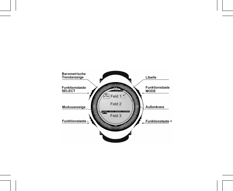
9
Es gliedert sich in die folgenden Bereiche:
• Der Außenkranz umläuft das gesamte Display. Er ist in 36 Segmente unterteilt.
• Der barometrische Trendindikator ist ein Hilfsmittel zur rechtzeitigen Erkennung von Wetterumschwüngen.
• Feld 1 zeigt Ziffern oder Text; die Anzeige ist abhängig vom aktiven (Unter-)Modus.
• Feld 2 ist eine Ziffernanzeige mit Maßeinheiten.
• Der Modusindikatorbalken zeigt die vier Hauptmodi des Armbandcomputers (der aktive Modus ist durch
einen Pfeil gekennzeichnet).
• Feld 1 zeigt Ziffern oder Text.

10
1.5 MASSE UND EINHEITEN
Der Armbandcomputer kann Messwerte in metrischen oder in britischen Einheiten darstellen.
Einheit im metrischen System Einheit im britischen System
mft
m/min ft/min
°C °F
mbar inHg
1.5.1 Wahl der Maßeinheit
So ändern Sie die in der Anzeige verwendete Maßeinheit:
1. Falls Sie sich nicht bereits im Zeitmodus befinden, drücken Sie die [Mode]-Taste, bis die Pfeilmarkierung
des Modusindikators auf TIME zeigt.
2. Drücken Sie gleichzeitig [Mode] und [Select] und halten Sie beide Tasten 3 Sekunden lang gedrückt. In
Feld 1 erscheint kurz der Text "SET" und danach "UNI" (Abb. 43; die im Display verwendeten Abkürzungen
werden in Kapitel 8 dieses Handbuchs erklärt).
Hinweis: Falls Sie im Einrichtungsmodus 1 Minute lang keinen Knopf drücken, wechselt das Display automatisch
zurück in die Ausgangsanzeige.
WARNUNG: Falls Sie von der Maßeinheits-Einrichtungsansicht (UNI) kurz auf [Select] drücken (weniger als 2
Sekunden lang), öffnet sich die Kalibrierungsansicht des Drucksensors. Nähere Informationen hierzu finden
Sie im folgenden Abschnitt.
3. Drücken Sie die [Select]-Taste 2 Sekunden lang. Die rechts in Feld 2 sichtbare Längeneinheit (m oder ft)
beginnt zu blinken.
4. Drücken Sie [+], um zwischen den beiden Einheiten zu wechseln.
5. Drücken Sie nach der Wahl erneut [Select], um die nächste Einheit zu öffnen. In Feld 2 blinkt jetzt die
Druckeinheit (mbar oder inHg, direkt unter m bzw. ft).
6. Drücken Sie [+], um zwischen den beiden Einheiten zu wechseln.
7. Drücken Sie nach der Wahl erneut [Select], um die nächste Einheit zu öffnen. Die rechts über der Libelle
in Feld 1 sichtbare Temperatureinheit (°C oder °F) beginnt zu blinken.

11
8. Drücken Sie [+], um zwischen den beiden Einheiten zu wechseln.
9. Drücken Sie nach der Wahl erneut [Select], um die nächste Einheit zu öffnen. Die oben in der Mitte von
Feld 1 sichtbare Geschwindigkeitseinheit (m/min oder ft/min) beginnt zu blinken.
10. Drücken Sie [+], um zwischen den beiden Einheiten zu wechseln.
11. Drücken Sie nach der Wahl die Taste [Mode], um alle Änderungen zu bestätigen. Drücken Sie erneut
[Mode], um zur Hauptansicht des Zeitmodus (Uhranzeige) zurückzukehren.
Die Einstellung der Einheiten ist damit abgeschlossen.
1.6 KALIBRIERUNG DES DRUCKSENSORS
Der Drucksensor Ihres Armbandcomputers wird im Werk kalibriert. Nehmen Sie KEINE VERÄNDERUNG an
der Kalibrierung vor. Falls Sie versehentlich (s.o.) in den Sensorkalibriermodus gelangen, drücken Sie bitte
unverzüglich [Mode], um zur vorigen Ansicht zurückzukehren. Eine Änderung der Kalibrierung VERFÄLSCHT
sämtliche Höhen- und Luftdruckmesseinstellungen des Armbandcomputers.
Sie erkennen die Sensorkalibrierungsansicht an der Meldung "SNR" (Sensor) in Feld 1. Drücken Sie in dieser
Situation keinesfalls [+] oder [–], sondern schließen Sie die Ansicht mit [Select] (Rückkehr zum
Einheitswahlmodus UNI) oder [Mode] (Rückkehr zur Hauptansicht).
Falls die Drucksensorkalibrierung versehentlich geändert wurde, wenden Sie sich bitte an Ihren Suunto-
Kundendienst.
1.7 PFLEGE UND WARTUNG
Halten Sie sich genau an die in diesem Handbuch beschriebenen Pflegehinweise. Nehmen Sie keine sonstigen
Wartungsmaßnahmen an Ihrem Armbandcomputer vor. Versuchen Sie niemals, das Gehäuse zu öffnen oder
die seitlichen Knöpfe bzw. den Skalenring abzumontieren.
Schützen Sie Ihren Armbandcomputer vor Stößen, extremer Hitze und längerer direkter Sonneneinstrahlung.
Wenn Sie das Instrument für längere Zeit nicht benutzen, bewahren Sie es in sauberer und trockener Umgebung
bei Raumtemperatur auf.
Bei Bedarf kann der Armbandcomputer mit einem leicht feuchten Tuch (warmes Wasser) abgewischt werden.
Verwenden Sie milde Seife, um die Oberfläche von Verschmutzungen oder hartnäckigen Flecken zu reinigen

12
Setzen Sie das Instrument keinen starken chemischen Mitteln wie Benzin, Reinigungsmitteln, Aceton, Alkohol,
Klebstoffen oder Farbe aus, da diese das Gehäuse, die Dichtungen und die Oberfläche angreifen und
beschädigen würden.
Versuchen Sie niemals, den Armbandcomputer auseinanderzunehmen oder selber zu warten. Halten Sie den
Sensorbereich auf der Rückseite des Instruments frei von Staub und Sand. Stecken Sie niemals Stifte oder
sonstige spitze Gegenstände in die Sensoröffnungen!
1.7.1 Batteriewechsel
Der Armbandcomputer benötigt eine 3V-Lithiumbatterie des Typs CR 2430. Die Batterielebensdauer beträgt
etwa 12-18 Monate.
Eine Batterie-Warnanzeige erscheint auf dem Display, wenn noch etwa 5-15 % der Batteriekapazität verfügbar
sind. Wir empfehlen Ihnen, bereits in diesem Status die Batterie auszuwechseln.
Beachten Sie, dass extreme Kälte die Warnanzeige aktivieren kann, selbst wenn die Batterie noch voll
funktionsfähig ist. In diesem Fall ist das Auswechseln der Batterie nicht erforderlich. Falls die Anzeige jedoch
in Temperaturen über 10°C (50°F) erscheint, muss die Batterie ausgewechselt werden.
Hinweis: Häufiger und langer Gebrauch der Hintergrundbeleuchtung, des Höhenmessers und des Kompasses
verkürzt die Batterielebensdauer erheblich.
So wechseln Sie die Batterie:
1. Drehen Sie den Armbandcomputer auf die Rückseite.
2. Stecken Sie eine Münze in den Schlitz des Batteriefachdeckels.
3. Drehen Sie den Deckel nach links in die "Open"-Position.
4. Nehmen Sie den Deckel ab.
5. Nehmen Sie die alte Batterie aus dem Batteriefach und vergewissern Sie sich, dass der O-Ring und alle
Oberflächen sauber, trocken und unbeschädigt sind. Den O-Ring nicht dehnen oder ziehen.
6. Legen Sie die neue Batterie mit der positiven Polung (+) nach oben in das Batteriefach.
7. Vergewissern Sie sich, dass der O-Ring korrekt positioniert ist, um die Wasserdichtigkeit des
Armbandcomputers sicherzustellen. Setzen Sie den Batteriefachdeckel wieder ein.
8. Drehen Sie den Deckel mit Hilfe der Münze nach rechts in die "Close"-Position.

14
4. Drücken Sie [+], um die Minutenzahl zu erhöhen, oder [–], um sie zu reduzieren.
5. Drücken Sie nach der Einstellung erneut [Select], um zur nächsten Zeiteinheit zu wechseln. Die in der
Mitte von Feld 2 sichtbare Stundenanzeige beginnt zu blinken.
6. Drücken Sie [+], um die Stundenzahl zu erhöhen, oder [–], um sie zu reduzieren.
7. Drücken Sie nach der Einstellung erneut [Select], um zum nächsten Auswahlfeld zu wechseln. Sie können
jetzt in Feld 1 zwischen 12h- und der 24h-Anzeige wählen (die aktuelle Einstellung blinkt).
8. Drücken Sie [+] oder [–], um zwischen den beiden Optionen zu wechseln.
Hinweis: Wenn die 12h-Anzeige gewählt ist, steht unter der Stundenanzeige in Feld 2 die Tageszeitangabe
AM bzw. PM
9. Drücken Sie nach der Uhrzeiteinstellung erneut [Select], um zum Kalender zu wechseln. Die in der Mitte
von Feld 2 sichtbare Jahreszahl beginnt zu blinken (Abb. 12).
10. Drücken Sie [+], um die Jahreszahl zu erhöhen, oder [–], um sie zu reduzieren.
11. Drücken Sie nach der Einstellung erneut [Select], um zur Monatsanzeige zu wechseln. Die in der Mitte
von Feld 3 sichtbare Monatsanzeige beginnt zu blinken.
12. Drücken Sie [+], um die Monatszahl zu erhöhen, oder [–], um sie zu reduzieren.
13. Drücken Sie nach der Einstellung erneut [Select], um zur Tagesanzeige zu wechseln. Die rechts in Feld 3
sichtbare Tagesanzeige beginnt zu blinken.
14. Drücken Sie [+], um die Tageszahl zu erhöhen, oder [–], um sie zu reduzieren.
Hinweis: Nach dem Einstellen des Datums gibt der Armbandcomputer automatisch in Feld 1 den Wochentag
an. Dieser wird aus dem ab Werk programmierten Kalender ermittelt. Das Datum wird im amerikanischen
Format (Monat/Tag) dargestellt. Dieses Format kann nicht geändert werden.
15. Drücken Sie nach der Datumseinstellung [Mode], um die Änderungen zu übernehmen und zur Hauptanzeige
zu wechseln.
Hinweis: Falls Sie im Einrichtungsmodus 1 Minute lang keinen Knopf drücken, wechselt das Display automatisch
zurück in die Ausgangsanzeige.
Alle Zeitangaben sind jetzt vollständig.

15
2.2 WECKER (UNTERMODUS)
Sie können bis zu drei tägliche Weck- bzw. Erinnerungszeiten einprogrammieren.
Drücken Sie im TIME-Modus die [Select]-Taste, um den Wecker-Untermodus zu öffnen.
Die Anzeigefelder des Wecker-Untermodus (Abb. 39):
• Feld 1 zeigt an, ob zur ausgewählten Erinnerungszeit ein Alarmsignal ertönt (ON) oder nicht (OFF).
• Feld 2 zeigt den Wochentag die ausgewählte Erinnerungszeit.
• Feld 3 zeigt, auf welche Erinnerungszeit (1, 2 oder 3) sich die obigen Einstellungen beziehen.
Drücken Sie [+] oder [–], um Erinnerungszeit 1, 2 oder 3 auszuwählen. Die Änderung der Weckereinstellungen
wird im folgenden Abschnitt beschrieben.
2.2.1 Wecker/Erinnerung einstellen
1. Drücken Sie [+] oder [–], um Erinnerungszeit 1, 2 oder 3 auszuwählen.
2. Drücken Sie die [Select]-Taste 2 Sekunden lang. In Feld 1 blinkt der Text “ON” oder “OFF”.
3. Drücken Sie [+] oder [–], um zwischen den beiden Optionen zu wechseln.
4. Drücken Sie nach der Wahl erneut [Select], um zum nächsten Auswahlfeld zu wechseln. Die in der Mitte
von Feld 2 sichtbare Stundenanzeige beginnt zu blinken.
5. Drücken Sie [+], um die Stundenzahl zu erhöhen, oder [–], um sie zu reduzieren.
6. Drücken Sie nach der Einstellung erneut [Select], um zum nächsten Auswahlfeld zu wechseln. Die rechts
in Feld 2 sichtbare Minutenanzeige beginnt zu blinken.
7. Drücken Sie [+], um die Minutenzahl zu erhöhen, oder [–], um sie zu reduzieren.
8. Drücken Sie nach der Minuteneinstellung [Mode], um die Änderungen zu übernehmen und den
Einrichtungsmodus zu schließen. Das Weckersymbol (Glocke) erscheint links in Feld 2, wenn eine
Erinnerung aktiv ist.
Die Erinnerung ist jetzt programmiert. Um eine oder zwei weitere Erinnerungen zu aktivieren, wiederholen Sie
die Schritte 1-8 für die jeweilige Erinnerungszeit (1, 2 oder 3).
Hinweis: Die Lautstärke des Wecktons kann nicht geändert werden.

16
2.3 STOPPUHR (UNTERMODUS)
Die Stoppuhrfunktion des Armbandcomputers stoppt Zwischen- bzw. Rundenzeiten und eine oder zwei
Endzeiten. Ihre maximale Laufzeit ist 23 h 59 min 59 s.
Drücken Sie im TIME-Modus die [Select]-Taste zweimal direkt hintereinander, um den Stoppuhr-Untermodus
zu öffnen.
Die Anzeigefelder des Stoppuhr-Untermodus (Abb. 40):
• Feld 1 zeigt Sekunden und Zehntelsekunden.
• Feld 2 zeigt die Uhrzeit.
Feld 3 zeigt Stunden und Minuten sowie rechts den Text "stopwatch”.
2.3.1 Verwendung der Stoppuhr
Die Stoppuhr bietet Ihnen drei alternative Zeitnahmeoptionen:
• Einfache Zeitnahme (ohne Zwischenzeiten)
• Zwischen- bzw. Rundenzeiten
• zwei Endzeiten (zum Vergleich zwischen zwei Personen)
Einfache Zeitnahme ohne Zwischenzeiten:
1. Drücken Sie im Stoppuhr-Untermodus auf [+] um die Stoppuhr zu starten, zu stoppen und neu zu starten.
2. Drücken Sie [–], um die Stoppuhr nach der Zeitnahme auf Null zurückzusetzen.
Rundenzeitnahme:
1. Drücken Sie im Stoppuhr-Submodus die Funktionstaste [+], um mit der Zeitnahme zu beginnen.
2. Drücken Sie [–], um eine Zwischenzeit zu stoppen.
3. Drücken Sie [–], um die Zeitnahme fortzusetzen.
4. Drücken Sie zum Schluss [+], um die Zeitnahme zu beenden.
5. Drücken Sie [–], um die Stoppuhr nach der Zeitnahme auf Null zurückzusetzen.
Zeitnahme für zwei Personen:
1. Drücken Sie im Stoppuhr-Submodus die Funktionstaste [+], um mit der Zeitnahme zu beginnen.
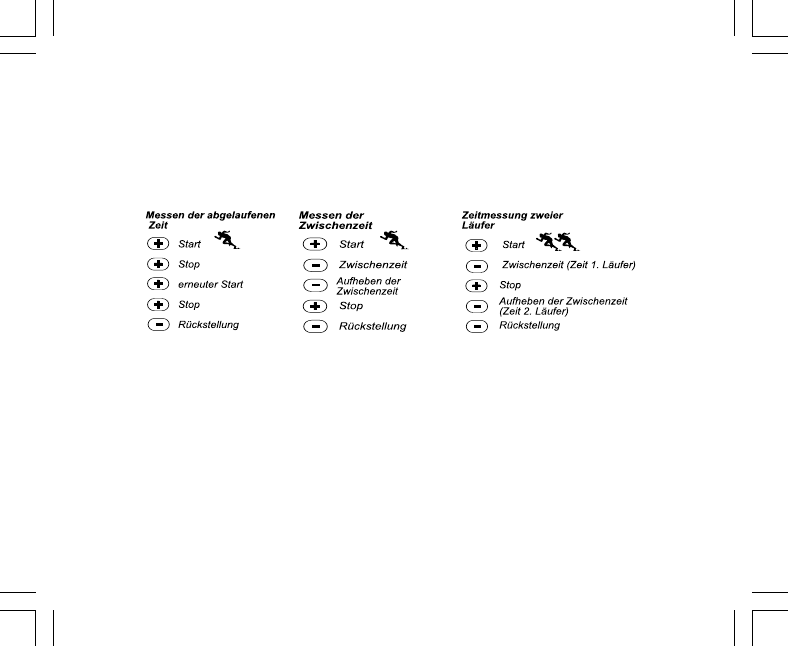
17
2. Drücken Sie [–], um die Endzeit der ersten Person zu stoppen.
3. Drücken Sie [+], um die Zeitnahme zu beenden.
4. Drücken Sie erneut [–], um die Endzeit der zweiten Person zu zeigen.
5. Drücken Sie [–], um die Stoppuhr nach der Zeitnahme auf Null zurückzusetzen.
Hinweis: Sie können bei laufender Zeitnahme andere Funktionen Ihres Armbandcomputers nutzen. Die Stoppuhr
läuft im Hintergrund weiter. Der blinkende Text “stopwatch” in Feld 3 zeigt an, dass die Stoppuhr aktiviert ist.
2.4 COUNTDOWN-TIMER (UNTERMODUS)
Drücken Sie im TIME-Modus die [Select]-Taste dreimal direkt hintereinander, um den Countdown-Untermodus
zu öffnen.
Die Anzeigefelder des Countdown-Untermodus (Abb. 41):
• Feld 1 zeigt die Sekunden.
• Feld 2 zeigt die Uhrzeit.
• Feld 3 zeigt Stunden und Minuten sowie rechts unten den Text "timer”.
2.4.1 Countdown einstellen
1. Drücken Sie die [Select]-Taste 2 Sekunden lang. Die in Feld 1 sichtbare Sekundenanzeige beginnt zu
blinken.
2. Drücken Sie [+], um die Sekundenzahl zu erhöhen, oder [–], um sie zu reduzieren.

18
3. Drücken Sie nach der Einstellung erneut [Select], um zur nächsten Zeiteinheit zu wechseln. Die rechts in
Feld 3 sichtbare Minutenanzeige beginnt zu blinken.
4. Drücken Sie [+], um die Minutenzahl zu erhöhen, oder [–], um sie zu reduzieren.
5. Drücken Sie nach der Einstellung erneut [Select], um zur nächsten Zeiteinheit zu wechseln. Die in der
Mitte von Feld 3 sichtbare Stundenanzeige beginnt zu blinken.
6. Drücken Sie [+], um die Stundenzahl zu erhöhen, oder [–], um sie zu reduzieren.
7. Drücken Sie nach der Stundeneinstellung [Mode], um die Änderungen zu übernehmen und den
Einrichtungsmodus zu schließen.
8. Der Countdown ist jetzt programmiert.
2.4.2 Countdown starten
So starten Sie den Countdown:
1. Drücken Sie im Countdown-Untermodus auf [+] um den Timer zu starten, zu stoppen und neu zu starten.
2. Drücken Sie [–], um den Timer nach Ende des Countdowns auf Null zurückzusetzen.
Hinweis: Sie können bei laufendem Countdown andere Funktionen Ihres Armbandcomputers nutzen. Der
Timer läuft im Hintergrund weiter. Der blinkende Text “timer” in Feld 3 zeigt an, dass der Timer aktiviert ist.
2.5 DUALZEIT-UNTERMODUS (ALTIMAX UND S-LANDER)«
Note: Diese Funktion ist nur in den Modellen Altimax und S-Lander verfügbar.
Drücken Sie im TIME-Modus die [Select]-Taste viermal direkt hintereinander, um den Dualzeit-Untermodus zu
öffnen.
Die Anzeigefelder des Dualzeit-Untermodus (Abb. 42):
• Feld 1 zeigt den Text "dUA".
• Feld 2 zeigt die Uhrzeit.
• Feld 3 zeigt die Zeit einer anderen Zeitzone (z.B. auf Reisen die Zeit Ihres Heimatlandes).
Wenn Sie die [+]-Taste drücken, erscheint in Feld 3 die Sekundenanzeige (nach 10 s automatische Rückkehr
zur Dualzeitanzeige).

19
2.5.1 Einstellung der Dualzeit
Öffnen Sie den Dualzeit-Untermodus und:
1. Drücken Sie die [Select]-Taste 2 Sekunden lang. Die in Feld 3 sichtbare Stundenanzeige beginnt zu blinken.
2. Drücken Sie [+], um die Stundenzahl zu erhöhen, oder [–], um sie zu reduzieren.
3. Drücken Sie nach der Einstellung erneut [Select], um zum nächsten Auswahlfeld zu wechseln. Die rechts
in Feld 3 sichtbare Minutenanzeige beginnt zu blinken.
4. Drücken Sie [+], um die Minutenzahl zu erhöhen, oder [–], um sie zu reduzieren.
5. Drücken Sie nach der Minuteneinstellung [Mode], um die Änderungen zu übernehmen und den
Einrichtungsmodus zu schließen.
6. Die Dualzeit ist jetzt programmiert.
Sie bleibt auch dann unverändert, wenn Sie die Zeitzone für die normale Uhrzeit (TIME-Hauptmodus) ändern.
Falls Sie z.B. Ihre Heimatzeitzone als Dualzeit eingeben, bleibt diese unverändert, auch wenn Sie im Urlaub
mehrere Zeitzonen bereisen und die Uhrzeit der Hauptanzeige jedesmal entsprechend umstellen.
Hinweis: Die Dualzeitfunktion ist unabhängig von den übrigen Zeitfunktionen und hat keinen Einfluss auf
diese. Für die Erinnerungs- und Speicherfunktionen ist ausschließlich die Normalzeit der Hauptanzeige relevant.
KAPITEL 3 HÖHENMESSMODUS (ALTI)
Der Höhenmessmodus (ALTI) umfasst folgende Funktionen:
• Wahl der Höheneinheit (Meter oder Fuß): Anzeigebereich -500 bis 9 000 m oder -1 600 bis 29 500 ft
• Auflösung: 5m oder 10 ft
• automatische Aktualisierung der Höhenangabe: während der ersten 3 Minuten im Sekundentakt, danach
alle 10 Sekunden oder wahlweise seltener
• automatischer 24h-Speicher: zeichnet im Stundenintervall Höhenangaben und Auf-/
Abstiegsgeschwindigkeiten auf
• Protokoll mit einer Erfassungskapazität von ca. 3800 Datensätzen (ein Datensatz umfasst Höhe, Auf-/
Abstiegsgeschwindigkeit und Uhrzeit)

20
So verwenden Sie den ALTI-Modus:
Falls Sie sich nicht bereits im Höhenmessmodus befinden, drücken Sie die [Mode]-Taste, bis die Pfeilmarkierung
des Modusindikators auf ALTI zeigt.
Die Anzeigefelder des ALTI-Modus (Abb. 1):
• Feld 1 zeigt die vertikale Auf- oder Abstiegsgeschwindigkeit
• Feld 2 zeigt Ihre momentane Höhe in Schritten von 5 m oder 10 ft (je nach gewählter Maßeinheit)
• Feld 3 zeigt die Uhrzeit.
• Der Außenkranz stellt die Höhe in 100m- oder 1000 ft-Einheiten grafisch dar, wobei eine volle Umrundung
1000 Einheiten darstellt.
WICHTIGER HINWEIS: Um den Höhenmesser im ALTI-Modus korrekt einstellen zu können, müssen Sie Ihre
aktuelle Höhe kennen. Diese Information können Sie einer topographischen Karte entnehmen, auf der
Höhenangaben vermerkt sind. Die Einstellung des Höhenmessers wird im folgenden Abschnitt beschrieben.
Nähere Informationen zur Beeinflussung des Höhenmessers durch die Umgebungstemperatur finden Sie auf
Seite 41 dieses Handbuchs.
Falls Sie Ihre Höhe nicht kennen, können Sie im Barometermodus Meeresspiegeldruck einstellen (s. S. 31,
Meeresspiegeldruck einstellen).
Wenn der Meeresspiegeldruck definiert ist, ermittelt der Höhenmesser anhand dieses Werts die aktuelle
Höhe mit einer Genauigkeit von einigen Dutzend Metern oder einigen hundert Fuß
Den aktuellen Meeresspielgeldruck erfahren Sie aus Zeitung, Nachrichten oder Wetterbericht, vom örtlichen
Flughafen oder auf Wetter-Infoseiten im Internet.
3.1 HÖHENMESSER EINSTELLEN
Sie können für den Höhenmesser drei Funktionen einstellen:
• Referenzhöhe (bekannte Höhe am derzeitigen Aufenthaltsort),
• Höhenalarm (gibt beim Erreichen der eingestellten Höhe ein Tonsignal)
• Protokollaufzeichnungsintervall (zeichnet im eingestellten Zeitabstand Höhe und Auf- bzw.
Abstiegsgeschwindigkeit auf)

21
Programmierung:
1. Drücken Sie die [Select]-Taste 2 Sekunden lang. In Feld 1 erscheint der Text "RE". Die in Feld 2 sichtbare
Höhenangabe beginnt zu blinken (Abb. 2).
2. Drücken Sie [+], um den Wert zu erhöhen, oder [–], um ihn zu reduzieren.
3. Drücken Sie nach der Referenzhöheneinstellung entweder [Mode], um die Änderungen zu übernehmen
und zur Hauptanzeige zurückzukehren, oder [Select], um zum nächsten Auswahlfeld zu wechseln. In Feld
1 blinkt der Text “ON” oder “OFF” (Abb. 3).
4. Drücken Sie [+] oder [–], um zwischen den beiden Optionen (Höhenalarm ein oder aus) zu wechseln.
5. Drücken Sie nach der Wahl erneut [Select], um zum nächsten Auswahlfeld zu wechseln. Der in der Mitte
von Feld 2 sichtbare Höhenalarm-Grenzwert beginnt zu blinken.
6. Drücken Sie [+], um den Wert zu erhöhen, oder [–], um ihn zu reduzieren.
7. Drücken Sie nach der Grenzwerteinstellung entweder [Mode], um die Änderungen zu übernehmen und zur
Hauptanzeige zurückzukehren, oder [Select], um zum nächsten Auswahlfeld zu wechseln. In Feld 1 erscheint
der Text "INT". Die in Feld 2 sichtbare Zeitangabe beginnt zu blinken (Abb. 4).
8. Drücken Sie [+] oder [–], um das gewünschte Intervall auszuwählen. Sie haben die Wahl zwischen vier
Aufzeichnungsintervallen: 20 Sekunden, 1 Minute, 10 Minuten oder 60 Minuten.
Empfohlene Intervalle:
Aktivität Intervall
Skilaufen 20 s oder 1 min
Fahrrad 20 s oder 1 min
Wandern 10 min
Bergsteigen 10 oder 60 min
Hinweis: Das gewählte Intervall a) gibt den Zeitabstand an, in dem Höhe, Auf-/Abstiegsgeschwindigkeit und
Uhrzeit im Protokoll vermerkt werden und b) bestimmt die maximal mögliche Protokollaufzeichnungsdauer.
Je kürzer das Intervall, desto exakter die Informationen, da die Daten häufiger erfasst werden. Zur
Protokollaufzeichnungsdauer siehe S. 25.
9. Drücken Sie nach der Intervalleinstellung [Mode], um die Änderungen zu übernehmen und den
Einrichtungsmodus zu schließen.

23
2. Drücken Sie auf [Mode], um die aktuelle Höhe als Nullpunkt zu verwenden und mit der Zeitnahme zu
beginnen.
Wenn Sie die Höhendifferenzmessung doch nicht verwenden möchten, drücken Sie entweder [+] oder [–], um
zur aktuellen Höhenangabe zurückzukehren, und danach [Mode], um den Einrichtungsmodus zu schließen.
Hinweis: Falls Sie im Einrichtungsmodus 1 Minute lang keinen Knopf drücken, wechselt das Display automatisch
zurück zum Hauptmodus, ohne den Höhenmesser auf Null zurückzusetzen.
3.3 24H-SPEICHER (UNTERMODUS)
Drücken Sie im ALTI-Modus die [Select]-Taste zweimal direkt hintereinander, um diesen Untermodus zu öffnen.
Die Anzeigefelder des 24h-Speicher-Untermodus (Abb. 15):
• Feld 1 zeigt die vertikale Auf- oder Abstiegsgeschwindigkeit
• Feld 2 zeigt Ihre momentane Höhe in Schritten von 5 m oder 10 ft (je nach gewählter Maßeinheit)
• Feld 3 zeigt die betreffende Stunde sowie links den Text "memory”.
• Der Außenkranz stellt die Höhe in 100 m- oder 1000 ft-Einheiten grafisch dar, wobei eine volle Umrundung
1000 Einheiten darstellt.
So rufen Sie die gespeicherten Informationen auf:
1. Drücken Sie [–], um in 1h-Schritten rückwärts zu scrollen und Auf-/Abstiegsgeschwindigkeit sowie Höhe
für die jeweilige Stunde abzurufen.
2. Drücken Sie [+], um wieder vorwärts zu scrollen.
Hinweis: Die hier gespeicherten Daten gehen auch beim Batteriewechsel nicht verloren.
3.4 PROTOKOLL (UNTERMODUS)
Drücken Sie im ALTI-Modus die [Select]-Taste dreimal direkt hintereinander, um diesen Untermodus zu öffnen.
Der Protokollmodus umfasst fünf verschiedene Anzeigen. Diese wechseln automatisch ab. Die erste Ansicht
wird 7 Sekunden lang eingeblendet, alle folgenden jeweils für 4 Sekunden.
Die Anzeigefelder der ersten Ansicht (Abb. 16):
• Feld 1 zeigt das Jahr

24
• Feld 2 zeigt den Text "LO” und die blinkende Nummer des Protokolls
• Feld 3 zeigt Monat und Tag des Protokolls. Links neben der Datumsangabe steht der Text “Log Book”.
Drücken Sie [–], um in umgekehrt chronologischer Reihenfolge durch die älteren Protokolle zu scrollen, und
[+], um wieder vorwärts bis zur jüngsten Aufzeichnung zu gelangen.
Die zweite Ansicht zeigt die Aufstiegsinformationen für das Protokoll (Abb. 17).
• Feld 1 zeigt die durchschnittliche Aufstiegsgeschwindigkeit während der Aktivität
• Feld 2 zeigt den Gesamtaufstieg
• Feld 3 zeigt nebeneinander die Texte "ASC” und “Log Book”.
Die dritte Ansicht zeigt die Abstiegsinformationen für das Protokoll (Abb. 18).
• Feld 1 zeigt die durchschnittliche Abstiegsgeschwindigkeit während der Aktivität
• Feld 2 zeigt den Gesamtabstieg
• Feld 3 zeigt nebeneinander die Texte "dSC” und “Log Book”.
Die vierte Ansicht zeigt die Anzahl der Auf- oder Abstiege während der Aktivität (Abb. 19).
• Feld 2 zeigt die Gesamtzahl der Auf- oder Abstiege
• Feld 3 zeigt nebeneinander die Texte "LAP” und “Log Book”.
Hinweis: Der Anzeigetext "Lap" (eigentlich "Runde") bezeichnet in dieser Anzeige einen Auf- oder Abstieg von
mindestens 50 m/150 ft.
Die fünfte Ansicht zeigt die Dauer der Protokollaufzeichnung (Abb.20).
• Feld 2 zeigt die Gesamtdauer der Protokollaufzeichnung
• Feld 3 zeigt nebeneinander die Texte "dUR” und “Log Book”.
Hinweis: Die maximal mögliche Länge des Protokolls ist abhängig vom gewählten Aufzeichnungsintervall. Im
Falle einer Zeitüberschreitung gibt der Armbandcomputer ein Warnsignal. Zur Einstellung des
Aufzeichnungsintervalls siehe S. 20, "Höhenmesser einstellen".

25
Maximale Aufzeichnungsdauer je Intervall: Aufzeichnungsintervall Maximale Dauer
20 Sekunden 10 Stunden
1 Minute 12 Stunden
10 Minuten 7 Tage
60 Minuten 10 Tage
3.4.1 Beginn und Ende der Protokollaufzeichnung
Modelle Vector und X-Lander:
Drücken Sie im ALTI-Hauptmodus oder im Höhendifferenz-Untermodus auf [+]. Ein Piepton und der in Feld 3
blinkende Text “Log Book” signalisieren den Beginn der Aufzeichnung.
Hinweis: In den Modellen Vector und X-Lander können die Protokolldaten nicht direkt während der Aufzeichnung
betrachtet werden. Sie sind erst nach Beendigung der Aufzeichnung abrufbar. Ältere Protokolle sind dagegen
jederzeit abrufbar.
Wenn Sie [+] ein zweites Mal drücken, stoppt die Aufzeichnung des Protokolls. Ein Piepton und das Erlöschen
des Texts “Log Book” signalisieren das Ende der Aufzeichnung.
Hinweis: Um versehentliche Aufzeichnungsstarts oder -stopps zu vermeiden, sollten die Modelle Vector und
X-Lander nicht unnötig im Höhenmessermodus belassen werden. Die aktive Protokollaufzeichnung läuft im
Hintergrund weiter, wenn Sie in einen anderen Modus wechseln.
Modelle Altimax und S-Lander:
Drücken Sie zum Start der Aufzeichnung innerhalb von 2 Sekunden zweimal auf [+]. Drücken Sie zum Beenden
der Aufzeichnung erneut zweimal innerhalb von 2 Sekunden auf [+].
Hinweis: Die Protokolle können in den hier beschriebenen Modellen (Altimax/S-Lander und Vector/X-Lander)
nicht von Hand gelöscht werden. Bei Überschreitung der Speicherkapazität werden die ältesten Aufzeichnungen
automatisch gelöscht.
Hinweis: Wenn Sie eine höhere Genauigkeit wünschen, starten Sie öfter neue Protokolle oder verringern Sie
die Aufnahmeintervalle.

26
3.4.2 Schnellzugriff
Diese Funktion ist nur in den Modellen Altimax und S-Lander verfügbar. Sie bietet einen schnellen Überblick
über Gesamtauf- und Abstieg in m oder ft sowie die Anzahl der Auf- bzw. Abstiege während der laufenden
Aufzeichnung.
Drücken Sie zum Aufrufen der Information von einer beliebigen Hauptmodusansicht aus auf [–]. Auf dem
Display erscheinen daraufhin nacheinander drei im 4-Sekunden-Takt wechselnde Ansichten.
• Die erste Ansicht zeigt den Gesamtaufstieg seit Beginn der laufenden Protokollaufzeichnung.
• Die zweite Ansicht zeigt den Gesamtabstieg seit Beginn der laufenden Protokollaufzeichnung.
• Die dritte Ansicht zeigt die Anzahl der Auf-/Abstiege während der laufenden Protokollaufzeichnung.
Nach der dritten Ansicht kehrt der Armbandcomputer automatisch zur Hauptanzeige des zuletzt aktiven Modus
zurück.
Hinweis: Sie können den Wechsel der drei Ansichten beschleunigen, indem Sie zwischendurch auf [–] drücken.
3.5 PROTOKOLLÜBERSICHT (UNTERMODUS)
Die Übersichtsfunktion zeigt eine Zusammenfassung aller aufgezeichneten Protokolle.
Drücken Sie im ALTI-Modus die [Select]-Taste viermal direkt hintereinander, um diesen Untermodus zu öffnen.
Der Übersichtsmodus umfasst vier verschiedene Ansichten.
Die Anzeigefelder der ersten Ansicht (Abb. 24):
• Feld 1 zeigt das Jahr der letzten Löschung der Protokollübersicht
• Feld 2 zeigt den Text "HIS"
• Feld 3 zeigt Monat und Tag der letzten Löschung der Protokollübersicht Links neben der Datumsangabe
steht der Text “Log Book”.
Drücken Sie [+], um zwischen den Ansichten zu wechseln.
Die Anzeigefelder der zweiten Ansicht (Abb. 25):
• Feld 1 zeigt den Text "HI"
• Feld 2 zeigt die größte seit der letzten Löschung erreichte Höhe

27
• Feld 3 zeigt das Datum dieses Höhenrekords und daneben den Text “Log Book”.
Die Anzeigefelder der dritten Ansicht (Abb. 26):
• Feld 1 zeigt den Text "ASC"
• Die Felder 2 und 3 zeigen den Gesamtaufstieg seit der letzten Löschung (max. 29 999,999 m/ft) Feld 2 wird
nur dann verwendet, wenn der Gesamtaufstieg mehr als 999 m/ft beträgt.
Die Anzeigefelder der vierten Ansicht (Abb. 27):
• Feld 1 zeigt den Text "dSC"
• Die Felder 2 und 3 zeigen den Gesamtabstieg seit der letzten Löschung (max. 29 999,999 m/ft) Feld 2 wird
nur dann verwendet, wenn der Gesamtabstieg mehr als 999 m/ft beträgt.
3.5.1 Protokollübersicht löschen
So löschen Sie die Protokollübersicht (Abb. 28):
1. Drücken Sie in einer der vier Ansichten der Übersichtsfunktion die [Select]-Taste 2 Sekunden lang. In Feld
1 erscheint der Text "CLR" und in Feld 2 "HIS". In Feld 3 blinkt der Text "nO" (Nein).
2. Drücken Sie [+], um zwischen den Alternativen "YES" und "nO" zu wechseln.
3. Wenn Sie die Übersicht wirklich löschen möchten, bestätigen Sie "YES" (Ja) mit [Mode].
Die Übersicht wird damit gelöscht. Das Datum der Löschung ist gleichzeitig das Anfangsdatum der neuen
Übersicht.
Hinweis: Falls Sie im Einrichtungsmodus 1 Minute lang keinen Knopf drücken, wechselt das Display automatisch
zurück in die Ausgangsanzeige.
Es empfiehlt sich, die alte Übersicht zu löschen, bevor Sie mit einer neuen Serie von Protokollaufzeichnungen
beginnen.

28
KAPITEL 4 BAROMETERMODUS (BARO)
Der Barometermodus (BARO) umfasst folgende Funktionen:
• Wahl der Druckmaßeinheit (mbar oder inHg); Anzeigebereich 300 bis 1 100 mbar/ 8,90 bis 32,40 inHg
• Auflösung: 1 mbar oder 0,05 inHg
• Luftdruckmessung im Stundentakt zur Feststellung der Wetterentwicklung
• automatischer 4-Tage-Speicher für die Luftdruckwerte (in Stundenintervallen für die letzten 6 Stunden,
danach in 6h-Intervallen).
• Temperaturausgleich (Temperaturen im angegebenen Bereich beeinflussen die Luftdruckmessung nicht)
• Temperaturbereich von -20° bis +60°C oder -5° bis +140°F
• Temperaturauflösung von 1°C bzw. 1°F.
Hinweis: Solange Sie den Armbandcomputer am Handgelenk tragen, wird die Temperaturmessung durch die
Körperwärme beeinflusst. Für eine präzise Temperaturmessung sollten Sie das Instrument daher ablegen
und mindestens 15 min warten, bevor Sie die Temperatur ablesen.
Wenn Sie den BARO-Modus länger als 15 Minuten aktiviert lassen, ohne dass sich Ihre Höhe verändert,
sollten Sie 1 Stunde warten, bis sich die Temperatureinstellung des Armbandcomputers eingependelt hat. Für
eine schnellere Aktualisierung des Thermometers drücken Sie viermal hintereinander [Mode], woraufhin der
Modus von neuem aktiviert wird.
So verwenden Sie den BARO-Modus:
Falls Sie sich nicht bereits im Barometermodus befinden, drücken Sie die [Mode]-Taste, bis die Pfeilmarkierung
des Modusindikators auf BARO zeigt.
Die Anzeigefelder des BARO-Modus (Abb. 5):
• Feld 1 zeigt die momentane Temperatur
• Feld 2 zeigt den absoluten Luftdruck
• Feld 3 zeigt die Uhrzeit.
• Der Außenkranz stellt den Luftdruck über 100 mbar oder 1 inHg grafisch dar, wobei eine volle Umrundung
100 mbar/1 inHg darstellt.

33
• Feld 2 zeigt die Peilung in Grad
• Feld 3 zeigt die Uhrzeit
• Der Außenkranz stellt die Nord-Süd-Richtung grafisch dar (N = ein Segment, S = drei Segmente).
Beim Vector ermöglicht eine grafische Libelle besonders genaue Richtungswerte (innerhalb von 3°) Bei der
Peilung sollte der Armbandcomputer vom Handgelenk abgenommen werden. Das Gerät ist waagerecht und
bereit für die Messung, wenn sich die Libelle in der Mitte befindet.
Die Kompassansicht ist nach jeder Aktivierung 45 Sekunden lang aktiv. Danach wechselt sie in den
Energiesparmodus, so dass in Feld 2 nur "---" steht. Drücken Sie zur Reaktivierung des Kompasses die [–]
Taste.
Hinweis: Verwenden Sie den Kompass nicht in der Nähe von Gebäuden oder starken künstlichen Magnetfeldern
(große Metallobjekte, Stromleitungen, Lautsprecher, Elektromotoren usw.).
Führen Sie Peilungen nur im Freien durch und nicht in Zelten, Höhlen. Unterständen usw.
5.1 PEILUNGSMESSUNG (UNTERMODUS)
Von der Hauptansicht des Kompasses aus können Sie die Peilungsmessfunktion aufrufen und Ihre angepeilte
Richtung mit Hilfe der Peilungssperre fixieren.
So gelangen Sie vom COMP-Modus aus zu diesem Untermodus:
1. Drücken Sie die [Select]-Taste 2 Sekunden lang. In Feld 1 blinkt der Text "OFF" (Abb. 8).
2. Drücken Sie [+] oder [–], um zwischen “OFF” und “ON” (Aus/Ein) zu wechseln.
3. Drücken Sie nach der Einstellung erneut [Select], um zur nächsten Zeiteinheit zu wechseln. Die in Feld 2
sichtbare Peilungsanzeige (Abb. 9) beginnt zu blinken.
4. Drehen Sie den Armbandcomputer waagerecht in die gewünschte Richtung. Drücken Sie [–], um die
angezeigte Peilung zu fixieren.
5. Sie können die fixierte Peilung bei Bedarf nachträglich korrigieren, indem Sie [Select] drücken und den
Wert mit [+] oder [–] anpassen.
6. Drücken Sie nach der Peilungseinstellung [Mode], um die Änderungen zu übernehmen und den
Einrichtungsmodus zu schließen.

34
Hinweis: Falls Sie im Einrichtungsmodus 1 Minute lang keinen Knopf drücken, wechselt das Display automatisch
zurück in die Ausgangsanzeige.
Hinweis: Die Peilungssperre blockiert die Kompassfunktion.
5.2 DEKLINATIONSKORREKTUR (UNTERMODUS)
Der Armbandcomputer erlaubt das Korrigieren der durch die Differenz zwischen magnetischem und
geografischem Nordpol hervorgerufenen Missweisung.
Für die zuverlässige Funktion des Kompasses ist die Anpassung des Deklinationswerts erforderlich.
Drücken Sie im COMP-Modus die [Select]-Taste, um den Wecker-Untermodus zu öffnen.
Die Anzeigefelder des Deklinationskorrektur-Untermodus (Abb. 33):
• Feld 1 zeigt die Deklinationsrichtung (W = West; E = Ost, OFF = neutral/keine Deklination)
• Feld 2 zeigt die Deklination in Grad
• Feld 3 zeigt den Text "dEC"
5.2.1 Lokale Deklination
1. Drücken Sie die [Select]-Taste 2 Sekunden lang. In Feld 1 blinkt der Text "OFF".
2. Drücken Sie [+] oder [–], um die Deklinationsrichtung zu wählen.
3. Drücken Sie nach der Wahl erneut [Select], um zum nächsten Auswahlfeld zu wechseln. Die in Feld 2
sichtbare Gradanzeige beginnt zu blinken.
4. Drücken Sie [+], um den Deklinationswinkel zu erhöhen, oder [–], um ihn zu reduzieren.
5. Drücken Sie nach der Gradeinstellung [Mode], um die Änderungen zu übernehmen und den
Einrichtungsmodus zu schließen.
Hinweis: Falls Sie im Einrichtungsmodus 1 Minute lang keinen Knopf drücken, wechselt das Display automatisch
zurück in die Ausgangsanzeige.
Die Missweisungskorrektur ist nun eingestellt.

35
5.3 KOMPASSKALIBRIERUNG
Der Kompass muss nach jedem Batteriewechsel neu kalibriert werden. Eine Neukalibrierung ist auch
erforderlich, falls der Armbandcomputer einem starken Magnetfeld, extremer Kälte oder sonstigen
funktionsbeeinträchtigenden Umweltbedingungen ausgesetzt wurde.
Hinweis: Sie sollten den Kompass außerdem neu kalibrieren, bevor Sie Ihn zum ersten Mal verwenden oder
zu einer längeren Trekkingtour o.ä. aufbrechen.
So kalibrieren Sie den Kompass:
1. Drücken Sie im COMP-Modus die [Select]-Taste zweimal direkt hintereinander. Feld 1 zeigt den Text "CMP"
Feld 3 zeigt den Text "CAL" (Abb. 34)
2. Drücken Sie die [Select]-Taste 2 Sekunden lang. In Feld 2 blinkt der Text “PUSH” (Abb. 35).
3. Drücken Sie [–], um mit der Kalibrierung zu beginnen.
4. In Feld 2 erscheint die Angabe "360°", und alle Segmente des Außenkranzes sind aktiviert (Abb. 36).
Halten Sie jetzt den Armbandcomputer waagerecht und drehen Sie ihn in waagerechter Position (Display
nach oben) langsam einmal um die eigene Achse. Die Drehrichtung ist hierbei egal. Während der Drehung
verlöscht ein Kranzsegment nach dem anderen. Nach der vollständigen Drehung meldet das Instrument
innerhalb einer Minute in Feld 2, ob die Kalibrierung erfolgreich war (Text “dOnE”, Abb. 37) oder wiederholt
werden muss (Text “PUSH” und “-”).
Hinweis: Es kann vorkommen, dass für die erfolgreiche Kalibrierung mehr als zwei vollständige Drehungen
erforderlich sind.
Hinweis: Es ist nicht erforderlich, dass während der Kalibrierung alle Segmente erscheinen oder erlöschen.
Hinweis: Falls in Feld 2 der Text "Fail" (Abb. 38) erscheint, nehmen Sie die Batterie heraus und setzen Sie sie
wieder ein, bevor Sie einen erneuten Kalibrierungsversuch unternehmen. Die Herausnahme der Batterie bewirkt
einen Neustart des Armbandcomputers.
5. Drücken Sie nach der erfolgreichen Kalibrierung [Mode], um die Änderungen zu übernehmen und den
Kalibrierungsmodus zu schließen.
Hinweis: Für ein korrektes Ergebnis ist es wichtig, dass Sie den Armbandcomputer während des gesamten
Kalibrierungsprozesses waagerecht halten.
Der Kompass ist jetzt kalibriert.

36
KAPITEL 6 HÄUFIG GESTELLTE FRAGEN
6.1 ALLGEMEINES
6.1.1 Ist der Armbandcomputer wasserdicht?
Ja, er ist wasserdicht bis in eine Tiefe von 30 m/100ft. Durch Regen und sonstige geringfügige Wassereinwirkung
wird seine Funktion nicht beeinträchtigt. Sie können mit dem Armbandcomputer auch schwimmen gehen. Er
ist jedoch KEIN Tauchinstrument.
6.1.2 Wie lange hält die Batterie?
Die Batterielebensdauer hängt von der Gebrauchsintensität ab. Sie verkürzt sich bei häufigem Gebrauch von
Hintergrundbeleuchtung, Höhenmesser, Kompass und Protokollfunktion. Eine Batterie-Warnanzeige erscheint
auf dem Display, wenn noch etwa 5-15 % der Batteriekapazität verfügbar sind. Dies gibt Ihnen ausreichend
Zeit, um die Batterie rechtzeitig zu wechseln.
6.1.3 Was hat es mit den Außenkranzsegmenten auf sich?
Im Höhenmessermodus zeigen die Kranzsegmente die Höhe über dem nächstkleineren Tausenderwert (ein
voller Kranz bedeutet jeweils 1000 m/ft). Wenn Sie die Höhendifferenzfunktion verwenden, zeigen die Segmente
die Höhenveränderung (1000 m/ft je voller Kreis), beim Aufstieg im Uhrzeigersinn und beim Abstieg in
entgegengesetzter Richtung.
Im Barometermodus zeigen die Kranzsegmente den Druck über dem nächstkleineren Hunderterwert (ein
voller Kranz bedeutet jeweils 100 mbar/inHg). Wenn Sie die Druckdifferenzfunktion verwenden, zeigen die
Segmente die Luftdruckveränderung, bei Druckanstieg im Uhrzeigersinn und bei Druckabfall in
entgegengesetzter Richtung.
Im Kompass-Hauptmodus markieren die Segmente die Nord-Süd-Richtung (N = ein Segment, S = drei
Segmente). Wenn Sie die Peilungsfixierung verwenden, zeigen die Segmente die Abweichung zwischen der
angepeilten und Ihrer tatsächlichen Richtung.

37
6.1.4 Was bedeutet es, wenn die Segmente gegen den
Uhrzeigersinn laufen?
Im Normalfall werden die Segmente von der 12-Uhr-Position aus im Uhrzeigersinn eingeblendet.
Bei den Differenzmessfunktionen ist auch die umgekehrte Richtung möglich. Sie bedeutet, dass sich der
gemessene Wert verringert (d.h. Abstieg bei der Höhen- bzw. Druckabfall bei der Luftdruckdifferenzmessung).
6.1.5 Was bedeuten die beiden Symbole über dem Modusbalken?
Das linke Symbol ist sichtbar, wenn der Höhenalarm aktiviert ist. Das rechte erscheint, wenn 1,2 oder 3
Erinnerungen programmiert sind.
6.2 ZEIT
6.2.1 Warum blinken die Außenkranzsegmente im Zeitmodus?
Die Kranzsegmente sind in erster Linie für die Kompassfunktion relevant. Daher beträgt ihre Anzahl 36,
entsprechend der 360°-Skala eines Kompasses. Im Zeitmodus zeigen sie die Sekunden. Da die Zahl der
Segmente jedoch unter 60 liegt, kann der Kranz nicht als fortlaufender Sekundenzeiger genutzt werden. Aus
diesem Grunde werden die Segmente lediglich im Sekundentakt ein- und ausgeblendet,
6.2.2 Was ist die längste Zeitspanne, auf die der Timer
programmiert werden kann?
Die maximale Länge des programmierbaren Countdowns beträgt 23 Stunden 59 Minuten und 59 Sekunden.
6.3 HÖHENMESSER
6.3.1 Kann ich meine Protokolle löschen?
Die Protokolle können nicht von Hand gelöscht werden.

44
Niedrigerer Punkt Höherer Punkt
Eingestellte Referenzhöhe (tatsächlicher Wert) 3280 ft
Angezeigte Höhe 9840 ft
Tatsächliche Außentemperatur +36,3 ºF +18,9 ºF
Normaltemperatur (Tabelle) +47,3 ºF +23,9 ºF
Temperaturabweichung (Echtwert – Normalwert) -9 ºF -5 ºF
Summe der Temperaturabweichungen -9 ºF + -5 ºF = -14 ºF
Tabelle 3. Beispielwerte in Fuß und Fahrenheit.
KAPITEL 7 VERFÜGBARE ERSATZTEILE
Batteriesatz (inkl. Batterie, Batteriefachdeckel und O-Dichtungsring)
Armband aus Kunststoff (Vector/Altimax) bzw. Leder, Velcro und Stoff (S-Lander/X-Lander)
Verlängerungsband (Kunststoff)
Skalierungsring (nur direkt von Suunto Oy im Zusammenhang mit Wartungsmaßnahmen erhältlich)
Suunto Oy bietet Ihnen einen kostengünstigen Wartungsservice für alle Armbandcomputermodelle.
Batterien sind im Sport- und Uhrenhandel erhältlich.
KAPITEL 8 ABKÜRZUNGEN
dEF – (engl. Default) Werkseitige Standardeinstellung des
Drucksensors, entspricht Standard-Luftdruck (1013
mbar/29,90 inHg) auf Meeresspiegelhöhe
SNR – Sensor (verwendet bei der Drucksensorkalibrierung)
RE – Referenzhöhe
CLR – (engl. Clear) Löschen
ASC – (engl. Ascent) Aufstieg
dSC – (engl. Descent) Abstieg
bEG – Beginn
HIS – (engl. History) Chronologische
Übersicht
dUAF – Dualzeit
dUR – (engl. Duration) Dauer
CMP – (engl. Compass) Kompass
CAL – (engl. Calibration) Kalibrierung
bEA – (engl. Bearing) Peilung
46
KAPITEL 12 ENTSORGUNG DES GERÄTS
Bei der Entsorgung des Geräts sind die für Elektronikschrott geltenden Vorschriften zu
beachten. Nicht im Hausmüll entsorgen! Defekte Altgeräte können bei jedem Suunto-
Vertragshändler abgegeben werden.
Veränderungen auftreten. Auch sonstige eventuell auftretende Produktfehler, die auf anleitungswidrigen oder
zweckfremden Gebrauch des Geräts zurückzuführen sind, sind von den hier genannten Garantieleistungen
ausgeschlossen.
Es gibt keine weiteren Garantieleistungen als oben aufgeführt.
Der Kunde kann sich bei Fragen zum Recht auf Reparatur in der Garantiezeit mit unserem Kundendienst in
Kontakt setzen. Dort werden auch Reparaturautorisierungen für außerhalb unserer Firma vorgenommene
Reparaturleistungen erteilt.
Weder Suunto Oyj noch Suunto Europe oder Suunto USA/Canada haften für Unfälle oder Schäden, die aus
dem Gebrauch des Produkts zu anderen als den in der Bedienungsanleitung genannten Einsatzzwecken
resultieren. Suunto Oyj übernimmt keinesfalls die Verantwortung für Verluste oder Ansprüche dritter Personen,
die durch den Gebrauch dieses Produkts auftreten könnten.
Suunto’s Qualitäts-Versicherungssystem wurde durch Det Norske Veritas bescheinigt, hinsichtlich ISO 9001
in allen Operationsbereichen der Firma SUUNTO Oyj diese Norm zu erfüllen (Qualitätszertifikat No. 96-HEL-
AQ-220).

1
GUÍA DEL USUARIO
DATOS DE CONTACTO DE SERVICIO AL CLIENTE
Suunto Oy Tel. +358 9 875870
Fax +358 9 87587301
Suunto USA Tel. 1 (800) 543-9124
Canadá Tel. 1 (800) 776-7770
Centro de llamadas para Europa Tel. +358 2 284 11 60
Sitio web de Suunto www.suunto.com
ES

2
ÍNDICE
CAPÍTULO 1 INTRODUCCIÓN .......................................................... 6
1.1 INFORMACIÓN GENERAL .......................................................................................... 6
1.2 FUNCIONES PRINCIPALES (MODOS) ....................................................................... 6
1.2.1 Funciones de retroiluminación ...................................................................... 7
1.2.2 Resistencia al agua ....................................................................................... 7
1.3 FUNCIONES DE LOS BOTONES ............................................................................... 7
1.3.1 Botón [Mode] ................................................................................................. 7
1.3.2 Botón [+] ........................................................................................................ 8
1.3.3 Botón [-] ......................................................................................................... 8
1.3.4 Botón [Select] ................................................................................................ 8
1.4 PANTALLA DE LCD ..................................................................................................... 9
1.5 MEDICIONES Y UNIDADES ...................................................................................... 10
1.5.1 Selección de las unidades de medida ......................................................... 10
1.6 CALIBRACIÓN DEL SENSOR DE PRESIÓN ............................................................. 11
1.7 CONSERVACIÓN Y MANTENIMIENTO ...................................................................... 11
1.7.1 Sustitución de la pila ................................................................................... 12
CAPÍTULO 2 MODO TIME ............................................................... 13
2.1 CÓMO AJUSTAR LA HORA ...................................................................................... 14
2.2 MODO SECUNDARIO DE ALARMA DIARIA .............................................................. 15
2.2.1 Cómo activar las alarmas diarias ................................................................ 15
2.3 MODO SECUNDARIO DE CRONÓMETRO .............................................................. 16
2.3.1 Cómo usar el cronómetro ............................................................................ 16
2.4 MODO SECUNDARIO DE TEMPORIZADOR DE CUENTA ATRÁS .......................... 18
2.4.1 Cómo ajustar el temporizador de cuenta atrás............................................ 18

4
CAPÍTULO 6 PREGUNTAS FRECUENTES ...................................... 37
6.1 GENERALIDADES ..................................................................................................... 37
6.1.1 ¿Es resistente al agua el ordenador de muñeca? ....................................... 37
6.1.2 ¿Cuánto tiempo durará la pila? ................................................................... 37
6.1.3 ¿Qué significan los segmentos de la circunferencia? ................................. 37
6.1.4 ¿Por qué los segmentos de la circunferencia se mueven hacia la izquierda
(en el sentido contrario a las agujas del reloj)? .......................................... 38
6.1.5 ¿Por qué hay dos símbolos sobre la barra indicadora de modo y qué
significan? ................................................................................................... 38
6.2 MODO TIME .............................................................................................................. 38
6.2.1 ¿Por qué crece y se reduce el número de segmentos activos de la
circunferencia cuando estoy en el modo Time?.......................................... 38
6.2.2 ¿Cuál es el tiempo máximo que puedo tener activado el temporizador? .... 39
6.3 MODO ALTIMETER ................................................................................................... 39
6.3.1 ¿Cómo puedo borrar el diario? ................................................................... 39
6.3.2 ¿De qué forma se borra automáticamente el diario? .................................. 39
6.3.3 ¿Cuántos diarios puedo grabar? ................................................................. 39
6.3.4 ¿En qué consiste la lectura de duración? ................................................... 40
6.3.5 ¿Cuál es la cifra máxima en metros/pies de los datos de ascenso o
descenso vertical total del historial de diarios? .......................................... 40
6.3.6 Si desciendo caminando desde una altitud de 5.000 pies hasta los 3.000
pies y vuelvo a ascender hasta los 8.000 pies, ¿indicará el modelo Vector
estas altitudes o las compensará? ............................................................. 40
6.3.7 ¿Por qué indica la medición de ascenso/descenso vertical distintas lecturas
incluso si estoy dentro de una misma habitación y no salgo de ella? ......... 41
6.4 MODO BAROMETER ................................................................................................ 42

6
CAPÍTULO 1 INTRODUCCIÓN
1.1 INFORMACIÓN GENERAL
El ordenador de muñeca es un fiable instrumento electrónico de alta precisión diseñado para uso recreativo.
Los entusiastas de los deportes al aire libre que practican deportes como el esquí, el piragüismo, la escalada,
el senderismo y el ciclismo pueden confiar en la exactitud del ordenador de muñeca. Este ordenador de
muñeca diseñado ergonómicamente pesa 55 gramos y se fabrica con una pantalla de LCD que incluye una
gran pantalla para números diseñada para una lectura clara en prácticamente cualquier situación.
Nota: El ordenador de muñeca no debe utilizarse para la obtención de mediciones que requieran una precisión
profesional o industrial y no debe usarse para obtener mediciones durante actividades como la caída libre, el
paracaidismo o el parapente o el vuelo en autogiro o en ultraligero.
NOTA IMPORTANTE: UNA PÁGINA DESPLEGABLE QUE SE ENCUENTRA EN LA CUBIERTA INTERIOR
DE ESTE MANUAL ILUSTRA GRÁFICAMENTE E IDENTIFICA LAS PROPIEDADES DEL ORDENADOR DE
MUÑECA Y DE LA PANTALLA DE LCD. ESTA PÁGINA HA SIDO DISEÑADA PARA AYUDAR A LOS USUARIOS
A COMPRENDER LAS DISTINTAS FUNCIONES Y EL PROCESO QUE SE SIGUE PARA CONFIGURARLAS.
1.2 FUNCIONES PRINCIPALES (MODOS)
A pesar de que la guía del usuario es aplicable a todos los modelos de ordenador de muñeca, en la tabla
siguiente se indican las funciones y diferencias de manejo de los distintos modelos.
Funciones Modelos de ordenador de muñeca
Altimax S-Lander Vector X-Lander
Hora SÍ SÍ SÍ SÍ
Altímetro SÍ SÍ SÍ SÍ
Barómetro SÍ SÍ SÍ SÍ
Brújula - - SÍ SÍ
Dentro de cada una de estas funciones, los modos secundarios asociados ofrecen un grado mayor de utilidad
al propietario.

7
Todas las características esenciales, así como los modos secundarios, se explican en detalle a continuación
de esta sección.
Nota: Los modelos de ordenador de muñeca Vector y X-Lander comparten las mismas funciones que se
comparten entre el Altimax y el S-Lander. La diferencia consiste en que los modelos Vector y Altimax cuentan
con una resistente carcasa de plástico mientras que los modelos X-Lander y S-Lander tienen un exterior de
aluminio pulido.
1.2.1 Funciones de retroiluminación
El ordenador de muñeca cuenta con una retroiluminación electroluminiscente. Para activarla, presione y
mantenga presionado el botón [Mode] durante 2 segundos. La retroiluminación permanece encendida durante
5 segundos. Si se presiona el botón [Mode] durante este intervalo, se reinicia el periodo de 5 segundos para
continuar con la retroiluminación.
1.2.2 Resistencia al agua
Este producto es resistente al agua. La resistencia al agua se ha probado a una profundidad de 30 m de
acuerdo con la norma ISO 2281 (www.iso.ch).
Nota: El ordenador de muñeca no es un instrumento de inmersión.
1.3 FUNCIONES DE LOS BOTONES
Para el manejo del ordenador de muñeca se utilizan cuatro botones: [Mode], [+] (ENCENDER/APAGAR), [-]
(rumbo rápido) y [Select].
1.3.1 Botón [Mode]
Se encuentra en la parte superior derecha del ordenador de muñeca.
• En el nivel de modo principal, el usuario puede presionar el botón [Mode] para seleccionar o para moverse
de un modo a otro o de una función a otra (TIME, ALTI, BARO, COMP).
• En el nivel de modo secundario, una presión en el botón [Mode] devuelve al usuario al nivel de modo
principal.
• En el proceso de configuración, una presión en el botón [Mode] acepta los cambios o preferencias. Al

9
El botón
MODE
El botón
SELECT
El botón - El botón +
Indicador
del modo
Circumferencia
exterior
Brubuja de
nivelación
Indicador de
la tendencia
barométrica
Campo 1
Campo 2
Campo 3
1.4 PANTALLA DE LCD
La pantalla se ha diseñado para proporcionar la máxima claridad y facilidad al usuario.
Se divide en varias zonas o áreas.
• La circunferencia exterior delimita el contorno de la pantalla de LCD. Los segmentos periféricos se encuentran
en la circunferencia exterior.
• Un indicador de tendencia barométrica proporciona una referencia rápida para la previsión de las condiciones
meteorológicas.
• El campo 1 muestra valores de número o texto en función del modo o el modo secundario en el que se
encuentra el usuario.
• El campo 2 muestra números grandes y/o la unidad de medida relacionada con la función.
• Una barra indicadora de modo muestra los modos (funciones) principales del ordenador de muñeca (una
punta de flecha triangular situada inmediatamente debajo de la barra indica el modo que está viendo el
usuario).
• El campo 3 muestra números
y/o texto.

11
7. Tras mostrar la unidad de medida deseada, PRESIONE el botón [Select] para pasar a la unidad siguiente.
En la parte superior derecha del campo 1 (justo sobre la burbuja), parpadeará la indicación “°C” o “°F”.
8. PRESIONE el botón [+] para cambiar entre “°C” y “°F”.
9. Tras mostrar la unidad de medida deseada, PRESIONE el botón [Select] para pasar a la unidad siguiente.
En la parte superior central del campo 1, parpadeará la indicación “m/min” o “ft/min”.
10.PRESIONE el botón [+] para cambiar entre “m/min” y “ft/min”.
11.Tras mostrar la unidad de medida deseada, PRESIONE el botón [Mode] para aceptar los cambios.
PRESIONE el botón [Mode] de nuevo para volver al modo principal de hora.
La selección de las unidades de medida ha finalizado.
1.6 CALIBRACIÓN DEL SENSOR DE PRESIÓN
Ésta es una CALIBRACIÓN DE AJUSTE DE FÁBRICA. Si se encuentra en este modo, le recomendamos
encarecidamente que salga de ajuste presionando el botón [Mode]. La calibración de este ajuste AFECTARÁ
NEGATIVAMENTE a los ajustes de altitud y presión barométrica del ordenador de muñeca.
En este ajuste, el usuario verá la indicación “SNR” (sensor) en el campo 1. No presione el botón [+] o [-] para
ajustar la presión. Sólo debe salir de este ajuste presionando el botón [Select] para volver al modo de
configuración “UNI” o presionando el botón [Mode] para volver al modo principal.
Si la calibración del ajuste de presión ha sido alterada por error, póngase en contacto con nuestro departamento
de asistencia de productos.
1.7 CONSERVACIÓN Y MANTENIMIENTO
Realice únicamente los procedimientos detallados que se explican en este manual. No realice ninguna otra
operación de servicio técnico en el ordenador de muñeca ni intente abrir su carcasa ni desmontar los botones
o la corona.
Proteja el ordenador de muñeca de golpes, temperaturas extremas o exposición prolongada a la luz solar
directa. Mientras no lo utilice, debe conservar el ordenador de muñeca en un entorno limpio y seco a temperatura
ambiente.

12
Puede limpiar el ordenador de muñeca con un paño levemente humedecido (en agua caliente). Aplique una
solución jabonosa suave para eliminar manchas o marcas persistentes de una zona.
Evite la exposición del ordenador de muñeca a sustancias químicas agresivas, como gasolina, disolventes
limpiadores, acetona, alcohol, adhesivos y pinturas, dado que pueden causar daños a las juntas, la carcasa
y el acabado de la unidad.
No intente nunca desmantelar el ordenador de muñeca ni realice operaciones de servicio técnico por sí solo.
Asegúrese de que la zona que rodea a los sensores (en el reverso del instrumento) esté libre de suciedad y
arena. No inserte nunca ningún objeto en las aberturas para sensores del ordenador de muñeca.
1.7.1 Sustitución de la pila
El ordenador de muñeca utiliza una pila de litio de tres voltios del tipo: CR 2430. La máxima vida útil esperada
es de aproximadamente de 12 a 18 meses.
El indicador de carga insuficiente en la pila se activa cuando queda del 5% al 15% de la carga de la pila.
Cuando esto se produzca, recomendamos sustituir la pila.
Un clima extremadamente frío también activa el indicador de advertencia de carga de la pila. Incluso si el
indicador se activa, es posible que no tenga que sustituir la pila en estas condiciones. Si la temperatura es
superior a los 10 °C y se activa el indicador de carga insuficiente en la pila, debe sustituirla.
Nota: Un uso intensivo de la retroiluminación electroluminiscente, el altímetro y la brújula reduce
significativamente la vida útil de la pila.
Para sustituir la pila:
1. Dé la vuelta al ordenador de muñeca para ver el reverso.
2. Inserte una moneda en la ranura para moneda que se encuentra en la cubierta del compartimento de la
pila.
3. Gire la moneda en el sentido contrario a las agujas del reloj hasta la posición de apertura marcada en el
reverso de la carcasa.
4. Retire la cubierta del compartimento de la pila.
5. Retire la pila gastada del compartimento de la pila y asegúrese de que la junta tórica y todas las superficies
estén limpias y secas y libres de daños. No estire en exceso la junta tórica.

13
6. Inserte la nueva pila en el compartimento de la pila (con el lado negativo orientado hacia abajo y el lado
positivo hacia arriba).
7. Asegúrese de que la junta tórica esté bien colocada para garantizar la estanqueidad del ordenador de
muñeca. Vuelva a montar la cubierta del compartimento de la pila en el reverso del ordenador de muñeca.
8. Vuelva a insertar una moneda en la ranura para moneda. Por último:
9. Gire la moneda en el sentido de las agujas del reloj hasta la posición de cierre marcada en el reverso de
la carcasa.
Nota: La sustitución de la pila debe realizarse con el máximo cuidado para garantizar que el ordenador de
muñeca siga siendo resistente al agua. El operador es responsable de tomar las precauciones oportunas
para garantizar que el ordenador de muñeca siga siendo resistente al agua.
Tras cada sustitución de la pila, es necesario calibrar el sensor magnético. Los detalles sobre cómo realizar
este procedimiento se encuentran en la sección Calibración de la brújula de este manual.
CAPÍTULO 2 MODO TIME
El modo Time ofrece al usuario:
• Una indicación de hora ajustable de 24/12 horas.
• Un calendario preprogramado hasta el año 2089.
• Tres modos secundarios: tres alarmas diarias, cronómetro y temporizador de cuenta atrás.
Para ver y usar el modo Time:
Compruebe la posición de la barra indicadora de modo. Si la flecha de modo no se encuentra en TIME,
PRESIONE el botón [Mode] hasta que la flecha se encuentre justo debajo de TIME en la barra.
En el modo TIME (figura 10):
• El campo 1 indica el día de la semana.
• El campo 2 indica la hora actual.
• El campo 3 indica la fecha (mes/día).
• La circunferencia exterior indica gráficamente el tiempo en segundos.
El modo Time y todos sus modos secundarios pueden ser ajustados a través del programa de configuración
del ordenador de muñeca.

14
2.1 CÓMO AJUSTAR LA HORA
Para ajustar la hora:
1. PRESIONE el botón [Select] y manténgalo presionado durante 2 segundos. En el campo 3, empezarán a
parpadear los segundos (figura 11).
2. PRESIONE el botón [+] para aumentar los segundos o PRESIONE el botón [-] para poner a cero los
segundos.
3. Tras mostrar los segundos deseados, PRESIONE el botón [Select] para pasar al ajuste siguiente. A la
derecha del campo 2, empezarán a parpadear los minutos.
4. PRESIONE el botón [+] para aumentar los minutos o PRESIONE el botón [-] para reducir los minutos.
5. Tras mostrar los minutos deseados, PRESIONE el botón [Select] para pasar al ajuste siguiente. En el
centro del campo 2, empezará a parpadear la hora.
6. PRESIONE el botón [+] para aumentar las horas o PRESIONE el botón [-] para reducir las horas.
7. Tras mostrar las horas deseadas, PRESIONE el botón [Select] para pasar al ajuste siguiente. En el campo
1, empezará a parpadear la opción de indicación horaria de 24 o 12 horas.
8. PRESIONE el botón [+] para cambiar entre "24hr" y "12hr".
Nota: Si elige la indicación de 12 horas, aparecerá AM o PM debajo de las horas en el campo 2.
9. Tras mostrar la indicación horaria deseada, PRESIONE el botón [Select] para pasar al ajuste siguiente. En
el centro del campo 2, empezará a parpadear el año (figura 12).
10.PRESIONE el botón [+] para aumentar el año o PRESIONE el botón [-] para reducirlo.
11.Tras mostrar el año deseado, PRESIONE el botón [Select] para pasar al ajuste siguiente. En el centro del
campo 3, empezará a parpadear el mes, en forma de número.
12.PRESIONE el botón [+] para aumentar el mes o PRESIONE el botón [-] para reducirlo.
13.Tras mostrar el mes deseado, PRESIONE el botón [Select] para pasar al ajuste siguiente. A la derecha del
campo 3, empezará a parpadear el día del mes.
14.PRESIONE el botón [+] para aumentar el día o PRESIONE el botón [-] para reducirlo.
Nota: Una vez que el usuario ha determinado el año, el mes y el día, el ordenador de muñeca indicará el día
de la semana en el campo 1. No es posible cambiar la visualización mes/día norteamericana al formato día/
mes.

15
15. Tras mostrar la fecha deseada, PRESIONE el botón [Mode] para aceptar los cambios y volver al modo
principal.
Nota: Si el usuario no presiona ningún botón durante 1 minuto en el modo de configuración, la pantalla cerrará
automáticamente la configuración.
El ajuste de la hora ha finalizado.
2.2 MODO SECUNDARIO DE ALARMA DIARIA
El ordenador de muñeca permite al usuario seleccionar e introducir ajustes para un máximo de tres alarmas.
En el modo TIME, PRESIONE una vez el botón [Select] para entrar en este modo secundario.
En el modo secundario de alarma diaria (figura 39):
• El campo 1 indica “ON” u “OFF” (el estado de activación de una alarma determinada).
• El campo 2 indica la hora de una alarma determinada.
• El campo 3 indica el número de la alarma (1, 2 ó 3) que está mostrando el usuario.
Presione el botón [+] o [-] para seleccionar las alarmas 1 ,2 ó 3. A continuación, cambie los ajustes de la forma
descrita en la sección siguiente.
2.2.1 Cómo activar las alarmas diarias
1. PRESIONE el botón [+] o [-] para seleccionar la alarma que desee activar (1, 2 ó 3).
2. PRESIONE el botón [Select] y manténgalo presionado durante 2 segundos. En el campo 1, empezará a
parpadear la opción “ON” u “OFF”.
3. PRESIONE el botón [+] para cambiar entre “ON” y “OFF”.
4. Tras mostrar el ajuste deseado, PRESIONE el botón [Select] para pasar al ajuste siguiente. En el centro
del campo 2, empezará a parpadear la hora.
5. PRESIONE el botón [+] para aumentar las horas o PRESIONE el botón [-] para reducir las horas.
6. Tras mostrar las horas deseadas, PRESIONE el botón [Select] para pasar al ajuste siguiente. A la derecha
del campo 2, empezarán a parpadear los minutos.
7. PRESIONE el botón [+] para aumentar los minutos o PRESIONE el botón [-] para reducir los minutos.

16
8. Tras mostrar los minutos deseados, PRESIONE el botón [Mode] para aceptar los cambios y salir del
programa de configuración. Aparecerá una pequeña campana en la parte inferior izquierda del campo 2,
para indicar que hay una alarma activada.
La configuración de la alarma ha finalizado. Para activar hasta tres alarmas, repita los pasos del 1 al 8 con la
alarma seleccionada (1, 2 ó 3).
Nota: No es posible cambiar el volumen de la alarma.
2.3 MODO SECUNDARIO DE CRONÓMETRO
El modo secundario de cronómetro del ordenador de muñeca permite obtener mediciones de tiempos parciales
y dos tiempos de finalización de hasta 23 horas, 59 minutos y 59 segundos.
En el modo TIME, PRESIONE dos veces el botón [Select] para entrar en este modo secundario.
En el modo secundario de cronómetro (figura 40):
• El campo 1 indica los segundos y décimas de segundo.
• El campo 2 indica la hora actual.
• El campo 3 indica las horas y minutos y, en el extremo derecho, “stopwatch”.
2.3.1 Cómo usar el cronómetro
Existen tres modos de temporización a disposición del usuario:
• Una medición de tiempo transcurrido.
• Una medición de tiempo parcial.
• Dos mediciones de tiempo de finalización.
En el modo de tiempo transcurrido:
1. PRESIONE el botón [+] para poner en marcha, parar y reanudar el cronómetro en el modo secundario de
cronómetro.
2. PRESIONE el botón [-] para poner a cero el cronómetro una vez parado éste.
En el modo de tiempo intermedio:
1. PRESIONE el botón [+] para poner en marcha el cronómetro en el modo secundario de cronómetro.
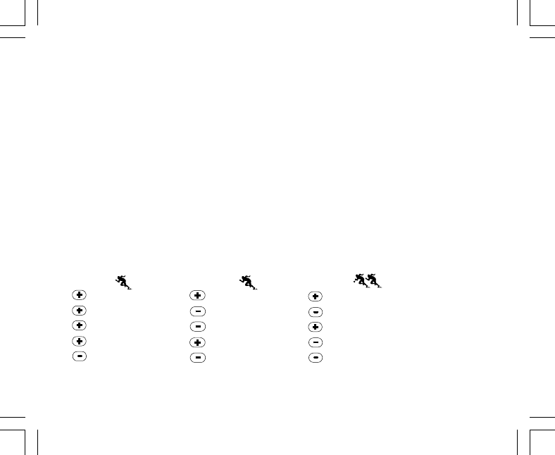
17
2. PRESIONE una vez el botón [-] para detener el cronómetro y para mostrar un tiempo intermedio.
3. PRESIONE una segunda vez el botón [-] para liberar la visualización del tiempo intermedio y volver a la de
cronómetro.
4. PRESIONE el botón [+] para parar el cronómetro.
5. PRESIONE el botón [-] para poner a cero el cronómetro una vez parado éste.
En el modo de tiempo de finalización para dos personas:
1. PRESIONE el botón [+] para poner en marcha el cronómetro en el modo secundario de cronómetro.
2. PRESIONE una vez el botón [-] para detener el cronómetro para mostrar el tiempo de finalización de la
primera persona.
3. PRESIONE el botón [+] para parar el cronómetro.
4. PRESIONE una segunda vez el botón [-] para liberar y mostrar el tiempo de finalización de la segunda
persona.
5. PRESIONE el botón [-] para borrar los tiempos del cronómetro y ponerlo a cero.
Nota: Si la función de cronómetro está activada, el cronómetro seguirá funcionando y se mantendrá en
segundo plano mientras el usuario se encuentra en otros modos principales o secundarios. El usuario puede
saber que el cronómetro sigue activado porque sigue parpadeando el texto “stopwatch” en el campo 3.
Iniciar Iniciar Iniciar
Parar Liberar Dividir (tiempo del primer corredor)
Reiniciar Liberar división Parar
Parar Parar Liberar división (tiempo del segundo corredor)
Borrar Borrar Borrar
Medición del tiempo Medición del tiempo Tiempos de los dos
transcurrido dividido corredores

18
2.4 MODO SECUNDARIO DE TEMPORIZADOR DE CUENTA
ATRÁS
En el modo TIME, PRESIONE tres veces el botón [Select] para entrar en este modo secundario.
En el modo secundario de temporizador de cuenta atrás (figura 41):
• El campo 1 indica los segundos.
• El campo 2 indica la hora actual.
• El campo 3 indica las horas y minutos y, en el extremo inferior derecho, la palabra “timer”.
2.4.1 Cómo ajustar el temporizador de cuenta atrás
1. PRESIONE el botón [Select] y manténgalo presionado durante 2 segundos. En el campo 1, empezarán a
parpadear los segundos.
2. PRESIONE el botón [+] para aumentar los segundos o PRESIONE el botón [-] para reducirlos.
3. Tras mostrar los segundos deseados, PRESIONE el botón [Select] para pasar al ajuste siguiente. A la
derecha del campo 3, empezarán a parpadear los minutos.
4. PRESIONE el botón [+] para aumentar los minutos o PRESIONE el botón [-] para reducir los minutos.
5. Tras mostrar los minutos deseados, PRESIONE el botón [Select] para pasar al ajuste siguiente. En el
centro del campo 3, empezará a parpadear la hora.
6. PRESIONE el botón [+] para aumentar las horas o PRESIONE el botón [-] para reducir las horas.
7. Tras mostrar las horas deseadas, PRESIONE el botón [Mode] para aceptar los cambios y salir del programa
de configuración.
8. La configuración del temporizador de cuenta atrás ha finalizado.
2.4.2 Cómo poner en marcha el temporizador de cuenta atrás
Para poner en marcha el temporizador de cuenta atrás:
1. PRESIONE el botón [+] para poner en marcha, parar y reanudar el temporizador en el modo secundario de
temporizador de cuenta atrás.
2. PRESIONE el botón [-] para poner a cero el temporizador una vez parado el éste.

19
Nota: Si la función de temporizador de cuenta atrás está activada, el temporizador seguirá funcionando y se
mantendrá en segundo plano mientras el usuario se encuentra en otros modos principales o secundarios. El
usuario puede saber que el temporizador de cuenta atrás sigue activado porque sigue parpadeando el texto
“timer” en el campo 3.
2.5 MODO SECUNDARIO DE SEGUNDO RELOJ (ALTIMAX Y
S-LANDER)
Nota: Esta función está presente en los ordenadores de muñeca Altimax y S-Lander.
En el modo TIME, PRESIONE cuatro veces el botón [Select] para entrar en este modo secundario.
En el modo de segundo reloj (figura 42):
• El campo 1 indica "dUA" para indicar el segundo reloj.
• El campo 2 indica la hora actual.
• El campo 3 indica la segunda hora (por ejemplo la hora de su lugar de origen).
El usuario puede mostrar los segundos durante este modo secundario presionando el botón [+]. Los segundos
aparecen en el campo 3 durante 10 segundos. A continuación, la pantalla vuelve la visualización del segundo
reloj.
2.5.1 Ajuste del segundo reloj
En el modo de segundo reloj:
1. PRESIONE el botón [Select] y manténgalo presionado durante 2 segundos. En el campo 3, empezarán a
parpadear las horas.
2. PRESIONE el botón [+] para aumentar las horas o PRESIONE el botón [-] para reducir las horas.
3. Tras mostrar las horas deseadas, PRESIONE el botón [Select] para pasar al ajuste siguiente. En el campo
3, a la derecha de las horas, empezarán a parpadear los minutos.
4. PRESIONE el botón [+] para aumentar los minutos o PRESIONE el botón [-] para reducir los minutos.
5. Tras mostrar los minutos deseados, PRESIONE el botón [Mode] para aceptar los cambios y salir del
programa de configuración.

21
NOTA IMPORTANTE: PARA PODER AJUSTAR LA ALTITUD EN EL MODO ALTIMETER, DEBE CONOCER
LA ALTITUD. PUEDE OBTENER ESA INFORMACIÓN CON AYUDA DE UN MAPA TOPOGRÁFICO EN EL
QUE SE INDIQUE LA UBICACIÓN ACTUAL JUNTO CON LA ALTITUD ASOCIADA. EL USUARIO PUEDE
CONTINUAR Y SEGUIR LAS INSTRUCCIONES DE AJUSTE DEL ALTÍMETRO QUE APARECEN EN LA
SECCIÓN SIGUIENTE. EN LA PÁGINA 41 DE ESTE MANUAL ENCONTRARÁ DETALLES SOBRE EL EFECTO
DE LA TEMPERATURA DEL AIRE SOBRE LA MEDICIÓN DE LA ALTITUD.
SI NO SE CONOCE LA ALTITUD, EL USUARIO PUEDE CONFIGURAR LA PRESIÓN A NIVEL DEL MAR EN
EL MODO BAROMÉTRICO (CONSULTE LA PÁGINA 31 SOBRE EL AJUSTE DE LA PRESIÓN A NIVEL DEL
MAR). EL AJUSTE DE LA PRESIÓN A NIVEL DEL MAR AJUSTARÁ EL ALTÍMETRO A LA ALTITUD ACTUAL,
CON UNA VARIACIÓN DE DIEZ METROS O POCOS CIENTOS DE PIES. LA INFORMACIÓN DE LA PRESIÓN
ACTUAL A NIVEL DEL MAR PUEDE OBTENERSE DE PERIÓDICOS, SERVICIOS DE NOTICIAS LOCALES,
PARTES METEOROLÓGICOS, LOS SERVICIOS DE UN AEROPUERTO LOCAL O CONSULTANDO LA
INFORMACIÓN METEOROLÓGICA A TRAVÉS DE INTERNET.
3.1 AJUSTE DEL ALTÍMETRO
Al ajustar el altímetro, es posible hacer tres procesos diferentes:
• Altitud de referencia (altitud conocida en la ubicación actual).
• Alarma de altitud (avisa al usuario cuando se alcance una altitud determinada programada previamente).
• El intervalo de grabación de diario (permite al usuario ver la altitud y la velocidad de movimiento vertical
dentro de un intervalo de tiempo elegido).
Para comenzar:
1. PRESIONE el botón [Select] y manténgalo presionado durante 2 segundos. En el campo 1 aparece el
texto “RE” (que indica "altitud de referencia"). En el campo 2, empezará a parpadear la altitud actual (figura
2).
2. PRESIONE el botón [+] para aumentar la altitud o PRESIONE el botón [-] para reducir la altitud.
3. Tras mostrar la altitud de referencia deseada, PRESIONE el botón [Mode] para aceptar los cambios y
volver al modo principal o PRESIONE el botón [Select] para pasar al ajuste siguiente. En el campo 1,
empezará a parpadear la opción “ON” u “OFF” (figura 3).

23
3.2 MODO SECUNDARIO DE MEDICIÓN DE LA VARIACIÓN
DE ALTITUD
En el modo Altimeter, PRESIONE una vez el botón [Select] para entrar en este modo secundario.
En el modo secundario de medición de variación de altitud (figura 13):
• El campo 1 indica la velocidad de ascenso o descenso vertical.
• El campo 2 indica la altitud actual en incrementos de 5 metros o 10 pies en función de la unidad de medida
seleccionada.
• El campo 3 indica el tiempo transcurrido. A la izquierda del tiempo aparece el texto “differ”.
• La circunferencia exterior representa gráficamente la altitud en cientos de metros o pies como fracciones
de mil unidades, siendo un círculo completo equivalente a 1.000.
El tiempo transcurrido se muestra hasta 39 horas y 59 minutos. Después de ese tiempo, aparecen tres guiones
(-:--) en la pantalla, en el campo 3. Si el usuario deja el modo secundario de medición de altitud a la vista en la
pantalla durante 12 horas, el ordenador de muñeca vuelve automáticamente al modo principal Time.
Este modo sigue funcionando en segundo plano y el usuario puede utilizar otros modos, con la comodidad de
que el usuario puede volver a este modo secundario para mostrar el estado actual.
Nota: El modo de medición de variación constituye una medición relativa. Cualquier variación de la altitud de
referencia durante la medición de variación de altitud afectará la altitud medida. Recomendamos que la
altitud de referencia se compruebe y ajuste siempre antes de iniciar una nueva medición.
3.2.1 Cómo iniciar la medición de la variación de altitud
1. PRESIONE el botón [Select] y manténgalo presionado durante 2 segundos. En el campo 1 aparece el
texto “SET”. En el campo 2, empezará a parpadear un cero (figura 14).
2. PRESIONE el botón [Modo] para aceptar el cero parpadeante e iniciar la medición de variación.
Si no desea iniciar la medición de la variación, PRESIONE el botón [+] o [-] para cambiar a la altitud actual y
PRESIONE el botón [Mode] para salir del programa de configuración.
Nota: Si el usuario no presiona ningún botón durante 1 minuto en el modo de configuración, la pantalla
volverá al modo principal sin poner a cero el altímetro.

29
• Un rango de temperaturas de entre -20 º0 y 60 ºC o de entre -5 ºF y 140 ºF.
• Una resolución de temperaturas de 1 ºC o F.
Nota: El calor corporal afectará a la temperatura si el ordenador de muñeca se lleva en la muñeca. Para
conseguir una lectura exacta, retire de la muñeca el ordenador de muñeca y espere al menos 15 minutos
antes de leer la temperatura.
Si se ha encontrado en el modo barométrico durante más de 15 minutos sin ninguna velocidad de movimiento
vertical, debe esperar al menos 1 hora a que el ordenador de muñeca ajuste la temperatura. Para realizar una
actualización más rápida de la temperatura, presione 4 veces el botón [Mode], para volver a entrar en el
modo.
Para ver y usar el modo Barometer:
Compruebe la posición de la barra indicadora de modo. Si la flecha de modo no se encuentra en BARO,
PRESIONE el botón [Mode] hasta que la flecha se encuentre justo debajo de BARO en la barra.
En el modo Barometer (figura 5):
• El campo 1 muestra la temperatura actual.
• El campo 2 indica la presión atmosférica absoluta actual.
• El campo 3 indica la hora actual.
• La circunferencia exterior muestra gráficamente la presión atmosférica en un rango de 100 milibares o 1
pulgada de mercurio, donde un círculo completo equivale a 100 milibares o 1 pulgada de mercurio, en
función de la unidad de medida elegida.
Nota: La presión absoluta es la presión actual en un lugar y un tiempo determinado. En este sentido, la
presión a nivel del mar es la presión correspondiente a nivel del mar.
4.1 MODO SECUNDARIO DE MEDICIÓN DE LA VARIACIÓN
DE PRESIÓN
La variación de presión no se refiere a la diferencia respecto a la presión a nivel del mar, sino a la presión
barométrica medida por el dispositivo.
En el modo Barometer, PRESIONE una vez el botón [Select] para entrar en este modo secundario.

30
En el modo secundario de medición de variación de presión (figura 30):
• El campo 1 muestra la variación de temperatura.
• El campo 2 indica la variación de presión atmosférica.
• El campo 3 indica el tiempo actual. A la izquierda del tiempo aparece el texto “differ”.
• La circunferencia exterior representa gráficamente la variación de presión. Un círculo completo equivale a
100 milibares o 1 pulgada de mercurio.
Este modo sigue funcionando en segundo plano y el usuario puede utilizar otros modos, con la comodidad de
que el usuario puede volver a este modo secundario para mostrar la lectura actual.
4.1.1 Cómo iniciar la medición de la variación de presión
1. PRESIONE el botón [Select] y manténgalo presionado durante 2 segundos. En el campo 1 aparece el
texto “SET”. En el campo 2, empezará a parpadear un cero (figura 29).
2. PRESIONE el botón [Modo] para aceptar el cero parpadeante e iniciar la medición de variación.
Si no desea iniciar la medición de la variación, PRESIONE el botón [+] o [-] para cambiar a la lectura de
presión barométrica actual y PRESIONE el botón [Mode] para salir del programa de configuración.
Nota: Si el usuario no presiona ningún botón durante 1 minuto en el modo de configuración, la pantalla cerrará
automáticamente la configuración.
4.2 MODO SECUNDARIO DE MEMORIA DE 4 DÍAS
En el modo Barometer, PRESIONE dos veces el botón [Select] para entrar en este modo secundario. Esta
función permite al usuario controlar los cambios de presión, como ayuda para prever los posibles cambios en
el estado del clima (por ejemplo, tormentas).
En el modo secundario de memoria de 4 días (figura 31):
• El campo 1 indica el día de la semana en el que se encuentra el usuario.
• El campo 2 indica la presión atmosférica.
• El campo 3 indica la hora y, en el lado izquierdo, el texto "memory".
• La circunferencia exterior representa gráficamente la variación de presión atmosférica. Un círculo completo
equivale a 100 milibares o 1 pulgada de mercurio.

31
Para ver la información recopilada en la memoria de 4 días:
PRESIONE el botón [-] para retroceder en incrementos de una hora durante las primeras seis horas y, a
continuación, en incrementos de 6 horas.
PRESIONE el botón [+] para volver a avanzar.
Nota: La sustitución de la pila no supone el borrado de esta información.
4.3 MODO SECUNDARIO DE PRESIÓN A NIVEL DEL MAR
La presión a nivel del mar es la presión respecto del nivel del mar, con lo que la presión leída en la pantalla
barométrica principal es la presión absoluta en la ubicación actual.
En el modo Barometer, PRESIONE tres veces el botón [Select] para entrar en este modo secundario.
En el modo secundario de presión a nivel del mar (figura 32):
• El campo 1 indica el texto "SEA".
• El campo 2 indica la presión actual a nivel del mar.
• El campo 3 indica la hora actual.
4.3.1 Ajuste de la presión a nivel del mar
El ajuste de la presión a nivel del mar puede usarse para el ajuste de la medición de altitud del ordenador de
muñeca si la altitud no se conoce.
Para ajustar la presión a nivel del mar:
1. PRESIONE el botón [Select] y manténgalo presionado durante 2 segundos. En el campo 2, empezará a
parpadear la presión actual a nivel del mar.
2. PRESIONE el botón [+] para aumentar la presión o PRESIONE el botón [-] para reducirla.
3. Tras mostrar la presión deseada, PRESIONE el botón [Mode] para aceptar los cambios y volver al modo
principal.
Una vez que el usuario completa este proceso, la medición de altitud en el ordenador de muñeca es correcta
dentro de un rango de aproximadamente diez metros o unos pocos cientos de pies.

34
Nota: Las lecturas de la brújula deben realizarse a distancia de objetos que presenten fuentes de magnetismo.
Evite los edificios, los objetos metálicos de gran tamaño, las líneas eléctricas, los altavoces, los motores
eléctricos, etc. Tome las lecturas siempre al aire libre, no dentro de tiendas de campaña, cuevas ni otros tipos
de refugios.
5.1 MODO SECUNDARIO DE SEGUIMIENTO DE RUMBO
El usuario tiene la opción de cambiar del modo de punto cardinal a la función de seguimiento de rumbo y
utilizar la función de bloqueo de rumbo en este modo para fines de seguimiento (figura 7).
En el modo principal de brújula:
1. PRESIONE el botón [Select] y manténgalo presionado durante 2 segundos. En el campo 1, empezará a
parpadear el texto "OFF" (figura 8).
2. PRESIONE el botón [+] o el botón [-] para cambiar entre “OFF" y "ON”.
3. Tras mostrar la selección deseada, PRESIONE el botón [Select] para pasar al ajuste siguiente. En el
campo 2, empezará a parpadear el rumbo actual en grados (figura 9).
4. Oriente el ordenador de muñeca en la dirección deseada. Bloquee el rumbo mostrado presionando el
botón [-].
5. Si es necesario, ajuste el rumbo bloqueado presionando el botón [Select] y ajustando a continuación el
valor con los botones [+] y [-].
6. Tras mostrar el rumbo cuyo seguimiento desee realizar, PRESIONE el botón [Mode] para aceptar los
cambios y salir del programa de configuración.
Nota: Si el usuario no presiona ningún botón durante 1 minuto en el modo de configuración, la pantalla cerrará
automáticamente la configuración.
Nota: El bloqueo en el modo secundario de seguimiento de rumbo bloquea la lectura de la brújula.
5.2 MODO SECUNDARIO DE AJUSTE DE DECLINACIÓN
El ordenador de muñeca permite al usuario compensar la diferencia existente entre el norte real y el norte
magnético.
Este proceso se realiza mediante el ajuste de la declinación, que permite al usuario obtener lecturas de
brújula correctas.

38
6.1.4 ¿Por qué los segmentos de la circunferencia se mueven
hacia la izquierda (en el sentido contrario a las agujas del reloj)?
Normalmente, siempre se mueven hacia la derecha (en el sentido de las agujas del reloj) a partir de la
posición de las 12.
Usted se encuentra en el modo de medición de variación y su unidad está indicando que el valor medido se
está reduciendo. En el modo normal, la representación de los segmentos se produce en el sentido de las
agujas del reloj, pero si se encuentra en un modo que permite representar variaciones (como el ascenso/
descenso vertical), todos los valores que se reduzcan se indican en el sentido contrario a las agujas del reloj
desde la posición central, mientras que todos los valores en aumento se indican en el sentido de las agujas
del reloj. Por tanto, lo que se indica es "menos" hacia la izquierda (sentido contrario a las agujas del reloj) y
"más" hacia la derecha (en el sentido de las agujas del reloj).
6.1.5 ¿Por qué hay dos símbolos sobre la barra indicadora de
modo y qué significan?
El símbolo de la izquierda indica que la alarma de altitud se ha activado y el símbolo de la derecha indica que
hay una, dos o tres alarmas diarias activadas.
6.2 MODO TIME
6.2.1 ¿Por qué crece y se reduce el número de segmentos activos
de la circunferencia cuando estoy en el modo Time?
La función principal de los segmentos depende del modo Compass, en el que se requiere una división en 36
segmentos debido a la escala de 360 grados de una brújula. En el modo Time, los segmentos indican el paso
de los segundos. Dado que el número de segundos es distinto del número de grados, resulta imposible
encender consecutivamente los segmentos, por tanto se encienden o se apagan y con ello permiten indicar
el transcurso de cada segundo.

41
entre los 5.000 y los 8.000 pues (inicio y fin). El hecho de que haya descendido hasta los 3.000 pies en el
trayecto no afecta a la variación absoluta de altitud vertical entre los puntos inicial y final.
Por último, la memoria automática de 24 horas mostrará esta información de la forma siguiente: Suponga
que inicia el trayecto en la cota de 5.000 pies a mediodía, le lleva 2 horas descender hasta los 3.000 pies y a
continuación otras cinco horas ascender hasta los 8.000 pues. Las pantallas desplazables de la memoria de
24 horas indican que su altitud era de 5.000 pies a las 12 horas, por ejemplo de 4.000 pies a las 13 horas,
3.000 pies a las 14 horas, por ejemplo 4.000 pies a las 15 horas, 5.000 pies a las 16 horas, 6.000 pies a las
17 horas, 7.000 pies a las 18 horas y por último 8.000 pies a las 19 horas.
Éstos son los distintos casos en los que la situación planteada influirá en las lecturas del ordenador de
muñeca.
Lo más importante que debe recordar es definir SIEMPRE en el ordenador de muñeca la altitud conocida.
Ésta es la única forma de obtener lecturas de altitud exactas.
6.3.7 ¿Por qué indica la medición de ascenso/descenso vertical
distintas lecturas incluso si estoy dentro de una misma
habitación y no salgo de ella?
La resolución de la velocidad de ascenso/descenso vertical es de 1 m/1 pie, mientras que la resolución de la
indicación de altitud es de 5 m/10 pies. Esto significa que la velocidad de ascenso/descenso puede indicar
movimiento a pesar de que usted permanezca a la misma altitud. Esto se debe a variaciones de la presión o
incluso un movimiento vertical dentro del rango de resolución de 5 m/10 pies.
En interiores, incluso las corrientes de aire reducidas y no detectables pueden provocar variaciones en la
presión del aire. Por ejemplo, si tiene abierta una ventana en un extremo de la casa, la corriente de aire puede
afectar a una habitación situada en el extremo contrario, provocando una variación tan mínima que usted no
la nota, al contrario que los sensores del ordenador de muñeca que sí la detectan. Dado que el ordenador de
muñeca mide el ascenso y el descenso basándose en las variaciones de la presión del aire, interpreta estos
cambios como movimiento vertical.

43
6.5 MODO COMPASS
6.5.1 ¿Para qué sirve la corona giratoria externa?
La finalidad de la corona giratoria es ofrecer la posibilidad de utilizar el instrumento como una brújula de
escala normal si se desea, usando la corona, por ejemplo, para indicar el norte en el modo de seguimiento de
rumbo o al salir de la pantalla de brújula para usar otro modo.
También puede usarse para hacer un seguimiento manual de su avance vertical, usando el indicador de norte
de la corona para marcar la altitud a partir de la cual desea controlar sus avances (es decir, usarlo como punto
cero). También puede marcar una altitud determinada, representada gráficamente por los segmentos de la
circunferencia, para obtener una medición inmediata de la variación. Sin embargo, la corona está relacionada
principalmente con la función de brújula.
6.5.2 ¿Cómo puedo conocer la declinación correcta de mi zona
para poder configurar mi ordenador de muñeca?
La declinación local, ya sea declinación este u oeste, suele estar marcada en los mapas con una exactitud de
un grado o medio grado.
6.6 EFECTO DE LA TEMPERATURA DEL AIRE SOBRE LA
MEDICIÓN DE ALTITUD
El término "presión atmosférica " se refiere al peso de la masa de aire situada sobre el observador: a una
mayor altitud, hay menos aire que a una altitud menor. El principio de un altímetro es medir las distintas
presiones del aire entre altitudes diferentes.
El peso del aire depende de la temperatura exterior. Por tanto, la variación de la presión del aire entre dos
altitudes también depende de la temperatura.
El cálculo de altitud del ordenador de muñeca se basa en la presión del aire a determinadas temperaturas
consideradas normales. Cada altitud tiene una temperatura normal definida. Las temperaturas normales en
las distintas altitudes se indican en la tabla 1.

3
2.4.2 Come attivare il timer di conto alla rovescia ................................................ 18
2.5 SOTTOMODALITÀ DUAL TIME (ALTIMAX, S-LANDER) ......................................... 19
2.5.1 Impostazione della funzione Dual Time ....................................................... 19
CAPITOLO 3 MODALITÀ ALTIMETER ........................................... 20
3.1 IMPOSTAZIONE DELL’ALTIMETRO ......................................................................... 21
3.2 SOTTOMODALITÀ ALTITUDE DIFFERENCE MEASUREMENT ............................. 23
3.2.1 Come attivare la misurazione della differenza di altitudine ......................... 24
3.3 SOTTOMODALITÀ 24-HOUR MEMORY .................................................................. 24
3.4 SOTTOMODALITÀ LOGBOOK ................................................................................ 24
3.4.1 Come attivare e arrestare un registro storico .............................................. 26
3.4.2 Pulsante Fast Cumulative ........................................................................... 22
3.5 SOTTOMODALITÀ LOGBOOK HISTORY ................................................................ 27
3.5.1 Cancellazione del registro storico ............................................................... 28
CAPITOLO 4 MODALITÀ BAROMETER ......................................... 29
4.1 SOTTOMODALITÀ PRESSURE DIFFERENCE MEASUREMENT .......................... 30
4.1.1 Come attivare la misurazione della differenza di pressione ........................ 30
4.2 SOTTOMODALITÀ 4-DAY MEMORY........................................................................ 31
4.3 SOTTOMODALITÀ SEA LEVEL PRESSURE ........................................................... 31
4.3.1 Impostazione della pressione a livello del mare ......................................... 32
4.4 INDICATORE DI TENDENZA BAROMETRICA ......................................................... 32
CAPITOLO 5 MODALITÀ COMPASS (VECTOR E X-LANDER) ........ 33
5.1 SOTTOMODALITÀ BEARING TRACKING ............................................................... 34
5.2 SOTTOMODALITÀ DECLINATION ADJUSTMENT .................................................. 35
5.2.1 Impostazione della declinazione locale ...................................................... 35
5.3 TARATURA DELLA BUSSOLA .................................................................................. 36

5
6.4.2 Il computer da polso mostra il futuro andamento delle condizioni
atmosferiche? ............................................................................................. 42
6.4.3 Cosa significano i termini “pressione assoluta” e “pressione relativa”? ...... 42
6.4.4 Cos’è la temperatura di compensazione? ................................................... 42
6.5 BUSSOLA ................................................................................................................. 42
6.5.1 A cosa serve la ghiera girevole esterna? .................................................... 43
6.5.2 Dove posso trovare la declinazione esatta per l’area in cui mi trovo da
impostare nel Computer da polso? ............................................................. 43
6.6 EFFETTO DELLA TEMPERATURA DELL’ARIA SULLA MISURAZIONE
DELL’ALTITUDINE ................................................................................................. 45
CAPITOLO 7 PARTI DI RICAMBIO DISPONIBILI ........................... 46
CAPITOLO 8 ABBREVIAZIONI ..................................................... 47
CAPITOLO 9 COPYRIGHT E MARCHIO DI FABBRICA ................... 47
CAPITOLO 10 CONFORMITÀ CE .................................................. 47
CAPITOLO 11 LIMITI DI RESPONSABILITÀ E CONFORMITÀ ISO
9001 ...................................................................................................
CAPITOLO 12 SMALTIMENTO DEL DISPOSITIVO ........................ 48

6
CAPITOLO 1 INTRODUZIONE
1.1 INFORMAZIONI GENERALI
Il computer da polso è uno strumento elettronico affidabile di alta precisione ad uso ricreativo. Gli appassionati
delle attività all’aria aperta che praticano sport quali lo sci, il kayaking, l’arrampicata, l’escursionismo e il
ciclismo, possono fare pieno affidamento sulla precisione del computer da polso. Il computer da polso ha un
design ergonomico, pesa solo 55 grammi ed è dotato di un display LCD caratterizzato da una visualizzazione
a numeri grandi per poter essere chiaramente visibile in qualsiasi condizione.
Nota: Il computer da polso non può comunque effettuare misurazioni che richiedono una precisione di tipo
industriale o professionale né essere utilizzato come strumento di misurazione quando si effettuano attività
come paracadutismo, deltaplano, parapendio e volo con veicoli quali il gyrocopter o aerei leggeri.
IMPORTANTE: UNA PAGINA STACCABILE INSERITA NELLA PARTE INTERNA DELLA COPERTINA
ANTERIORE DI QUESTO MANUALE ILLUSTRA E DEFINISCE LE PROPRIETÀ DEL COMPUTER DA POLSO
E DEL DISPLY LCD. QUESTA PAGINA HA LA FUNZIONE DI FACILITARE ALL’UTILIZZATORE LA
COMPRENSIONE DELLE FUNZIONI E DELLE PROCEDURE DI PROGRAMMAZIONE DI TALI FUNZIONI.
1.2 FUNZIONI PRINCIPALI (MODALITÀ)
Il presente manuale di istruzioni è valido per tutti i modelli di computer da polso; nella tabella sottostante sono
indicate le funzioni e le differenze di funzionamento dei diversi modelli.
Funzioni Modelli di computer da polso
Altimax S-Lander Vector X-Lander
Orologio SI’ SI’ SI’ SI’
Altimetro SI’ SI’ SI’ SI’
Barometro SI’ SI’ SI’ SI’
Bussola - - SI’ SI’
Per tutte le funzioni, le sottomodalità ad esse associate apportano ulteriori miglioramenti a vantaggio
dell’utilizzatore.

7
Tutte le funzioni principali e le sottomodalità sono illustrate in dettaglio in questa sezione.
Nota: I modelli di computer da polso Vector e X-Lander presentano le stesse caratteristiche, così come i
modelli Altimax e S-Lander. La differenza sta nel fatto che Vector e Altimax sono alloggiati in una cassa di
plastica resistente, mentre X-Lander e S-Lander in alluminio spazzolato.
1.2.1 Caratteristiche di retroilluminazione
Il computer da polso è dotato di una retroilluminazione elettroluminescente, che viene attivata tenendo premuto
per 2 secondi il pulsante [Mode]. La retroilluminazione rimarrà attiva per 5 secondi. Premendo il pulsante
[Mode] durante questo periodo, la funzione di retroilluminazione resterà attiva per un nuovo periodo di 5
secondi.
1.2.2 Resistenza all’acqua
Questo prodotto è resistente all’acqua. La resistenza all’acqua è stata testata fino alla profondità di 30m/100
piedi, conformemente alle direttive ISO 2281 (www.iso.ch).
Nota: Il computer da polso non è uno strumento per immersioni.
1.3 FUNZIONI DEI PULSANTI
Il funzionamento del computer da polso prevede l’utilizzo di quattro pulsanti: [Mode], [+] (ON/OFF), [-] (Fast
Bearing), e [Select].
1.3.1 Il pulsante [Mode]
E’ posto in alto a destra del computer da polso.
• Al livello di modalità principale, premendo il pulsante [Mode] l’utilizzatore può selezionare o passare da
una modalità o funzione a quella successiva (TIME, ALTI, BARO, COMP).
• Al livello di sottomodalità, premendo il pulsante [Mode] si ritorna al livello di modalità principale.
• Durante la procedura di programmazione, premendo il pulsante [Mode] vengono confermate le modifiche
o le impostazioni preferite. Premendo nuovamente il pulsante si tornerà al livello di modalità principale.
• Tenendo premuto il pulsante per 2 secondi viene attivata la funzione di retroilluminazione.

8
1.3.2 Il pulsante [+]
E’ posto in basso a destra del computer da polso.
• Durante la procedura di programmazione, premendo il pulsante [+] il valore da impostare cambia o scorre
in avanti.
• Nelle funzioni relative all’orologio e al registro, questo pulsante può fungere da pulsante di avvio/arresto (o
pulsante On/Off).
1.3.3 Il pulsante [-]
E’ posto in basso a sinistra del computer da polso.
• Durante la procedura di programmazione, premendo il pulsante [-] il valore da impostare cambia o scorre
all’indietro.
• Nei modelli Vector e X-Lander questo pulsante è indicato anche come pulsante “Fast Bearing”. Premendo
il pulsante [-] in qualsiasi modalità principale, comparirà brevemente la modalità Compass che visualizzerà
la bussola normale o la funzione di rilevamento del percorso (a seconda del display selezionato nella
modalità Compass).
• Nei modelli Altimax e S-Lander questo pulsante è indicato anche come pulsante “Fast Cumulative”.
Premendo il pulsante [-] in qualsiasi modalità principale comparirà brevemente l’informazione cumulativa
dell’attuale memorizzazione del registro.
Nota: Per ulteriori dettagli su questa caratteristica si rimanda alla pagina 27 di questo manuale.
1.3.4 Il pulsante [Select]
E’ posto in alto a sinistra del computer da polso.
• Al livello di modalità principale, premendo il pulsante [Select] si accede alle sottomodalità di una data
funzione o si ritorna alla modalità principale attiva in quel momento.
• Sia in modalità principale che in sottomodalità, tenendo premuto il pulsante [Select] per più di 2 secondi si
accede alla procedura di programmazione.
• Durante la procedura di programmazione, il pulsante [Select] consente di spostarsi tra le unità o i valori
impostabili e di determinare le impostazioni preferite.

9
1.4 DISPLAY LCD
Il display, ideato per offrire all’utilizzatore la massima chiarezza e semplicità,
è suddiviso in diverse zone o aree.
• La circonferenza esterna circonda il margine esterno del display LCD. Nella circonferenza esterna si trovano
i segmenti periferici.
• Un indicatore della tendenza barometrica fornisce una rapida indicazione delle condizioni atmosferiche
previste.
• Nel campo 1 sono visualizzati i valori numerici o di testo, a seconda della modalità o sottomodalità attiva in
quel momento.
• Nel campo 2 sono visualizzati numeri grandi e/o relativa
unità di misura della funzione.
• Una barra dell’indicatore di
modalità mostra le modalità
principali (funzioni) del computer da
polso (una freccia a triangolo posta
appena sotto la barra indica la
modalità visualizzata in quel
momento).
• Nel campo 3 sono visualizzati
numeri o testo.
Tasto MODE
Tasto SELECT
Tasto - Tasto +
Indicatore Mode
Circonferenz
Esterna
Livella a
bolla daria
Indicator trend
barometerico
Campo 1
Campo 2
Campo 3

11
successiva. I simboli °C or °F, posti nel Campo 1 in alto a destra (appena sopra la bolla), inizieranno a
lampeggiare.
8. PREMERE il pulsante [+] per passare da °C a °F.
9. Una volta selezionata l’unità di misura desiderata, PREMERE il pulsante [Select] per passare all’unità
successiva. I simboli “m/min” o “ft/min”, posti in alto al centro del Campo 1, inizieranno a lampeggiare.
10.PREMERE il pulsante [+] per passare da “m/min” a “ft/min”.
11.Una volta selezionata l’unità di misura desiderata, PREMERE il pulsante [Mode] per confermare le modifiche.
PREMERE nuovamente il pulsante [Mode] per tornare alla modalità principale Time.
La selezione delle unità di misura è così completata.
1.6 TARATURA DEL SENSORE DI PRESSIONE
Questa è un’IMPOSTAZIONE DI FABBRICA. Se vi trovate in questa modalità vi raccomandiamo caldamente
di uscire da questa impostazione premendo il pulsante [Mode]. La taratura di questa impostazione AVRÀ
CONSEGUENZE NEGATIVE su tutte le impostazioni barometriche e di altitudine del computer da polso.
In questa impostazione, comparirà la scritta “SNR” (Sensore) nel Campo 1. Non premete il pulsante [+] o [-]
per regolare la pressione. Uscite semplicemente premendo il pulsante [Select] per tornare alla modalità di
impostazione “UNI” o premendo il pulsante [Mode] per tornare alla modalità principale.
Se, per errore, la taratura della pressione impostata è stata modificata, rivolgersi al nostro Servizio di assistenza
tecnica.
1.7 CURA E MANUTENZIONE
Effettuare solo gli interventi illustrati in dettaglio in questo manuale. Non effettuare altri interventi sul computer
da polso e non tentare di aprire la cassa o di rimuovere i pulsanti o la ghiera.
Proteggere il computer da polso da urti, temperature troppo elevate o esposizione prolungata alla luce diretta
del sole. In caso di inutilizzo, conservare il computer da polso in un luogo pulito e asciutto, a temperatura
ambiente.
Il computer da polso può essere pulito con un panno leggermente umido (acqua calda). L’applicazione di
sapone delicato può mandar via macchie o segni particolarmente ostinati.

13
8. inserire nuovamente una moneta nell’apposita fessura e
9. girare la moneta in senso orario fino alla posizione di chiusura segnata sul fondo della cassa.
Nota: La sostituzione della batteria deve essere effettuata con la massima cautela, in modo da non
compromettere l’impermeabilità del computer da polso. E’ responsabilità dell’utilizzatore prestare la massima
attenzione affinché il computer da polso mantenga la sua impermeabilità.
Dopo ogni sostituzione di batteria è necessario tarare il sensore magnetico. Per i dettagli riguardanti questo
procedimento si rimanda alla sezione Taratura della bussola di questo manuale.
CAPITOLO 2 MODALITÀ TIME
La modalità Time (Orologio) dispone delle seguenti funzioni:
• un display di orologio regolabile a 24 o 12 ore;
• un calendario preprogrammato fino all’anno 2089 e
• tre sottomodalità: tre allarmi giornalieri; cronometro e timer di conto alla rovescia.
Per vedere e utilizzare la modalità Time:
controllare la barra dell’indicatore di modalità. Se la freccia di modalità non indica TIME, TENERE PREMUTO
il pulsante [Mode] finché la freccia non sia esattamente sotto TIME sulla barra.
Nella modalità TIME (Fig. 10):
• Nel Campo 1 è visualizzato il giorno della settimana.
• Nel Campo 2 è visualizzata l’ora attuale.
• Nel Campo 3 è visualizzata la data (mese/giorno).
• La circonferenza esterna mostra graficamente i secondi.
La modalità Time e tutte le relative sottomodalità si possono regolare attraverso la procedura di programmazione
del computer da polso.
2.1 COME REGOLARE L’OROLOGIO
Per regolare l’orologio:
1. TENERE PREMUTO il pulsante [Select] per 2 secondi. I secondi, visualizzati nel Campo 3, inizieranno a
lampeggiare (Fig. 1).

14
2. PREMERE il pulsante [+] per far scorrere i secondi in avanti oppure
PREMERE il pulsante [-] per azzerare i secondi.
3. Una volta selezionati i secondi desiderati, PREMERE il pulsante [Select] per passare all’impostazione
successiva. I minuti, visualizzati a destra del Campo 2, inizieranno a lampeggiare.
4. PREMERE il pulsante [+] per far scorrere i secondi in avanti oppure
PREMERE il pulsante [-] per far scorrere i secondi all’indietro.
5. Una volta selezionati i minuti desiderati, PREMERE il pulsante [Select] per passare all’impostazione
successiva. L’ora, visualizzata al centro del Campo 2, inizierà a lampeggiare.
6. PREMERE il pulsante [+] per far scorrere l’ora in avanti o PREMERE il pulsante [-] per far scorrere l’ora
all’indietro.
7. Una volta selezionata l’ora desiderata, PREMERE il pulsante [Select] per passare all’impostazione
successiva. L’impostazione dell’orologio a 24 o 12 ore, visualizzata nel Campo 1, inizierà a lampeggiare.
8. PREMERE il pulsante [+] o il pulsante [-] per passare dal formato a 24 ore a quello a 12 ore e viceversa.
Nota: Se si seleziona l’orologio a 12 ore, nel Campo 2 sotto l’ora comparirà il simbolo AM/PM.
9. Una volta selezionata l’impostazione oraria desiderata, PREMERE il pulsante [Select] per passare
all’impostazione successiva. L’anno, visualizzato al centro del Campo 2, inizierà a lampeggiare (Fig. 12).
10.PREMERE il pulsante [+] per far scorrere l’anno in avanti o PREMERE il pulsante [-] per far scorrere l’anno
all’indietro.
11.Una volta selezionato l’anno desiderato, PREMERE il pulsante [Select] per passare all’impostazione
successiva. Il numero che indica il mese, visualizzato al centro del Campo 3, inizierà a lampeggiare.
12.PREMERE il pulsante [+] per far scorrere il mese in avanti o PREMERE il pulsante [-] per far scorrere il
mese all’indietro.
13.Una volta selezionato il mese desiderato, PREMERE il pulsante [Select] per passare all’impostazione
successiva. La data, visualizzata a destra del Campo 3, inizierà a lampeggiare.
14.PREMERE il pulsante [+] per far scorrere la data in avanti o PREMERE il pulsante [-] per far scorrere la
data all’indietro.
Nota: Una volta selezionato l’anno, il mese e il giorno, il computer da polso visualizzerà il giorno della settimana
nel Campo 1. La visualizzazione americana della data in mese/giorno non può essere cambiata in quella
giorno/mese.

15
15.Una volta selezionata la data desiderata, PREMERE il pulsante [Mode] per confermare le modifiche e
tornare alla modalità principale.
Nota: Se per 1 minuto non viene azionato alcun pulsante mentre è attiva la modalità di programmazione, tale
modalità verrà automaticamente abbandonata.
La regolazione dell’orologio è così completata.
2.2 SUBMODALITÀ DAILY ALARM
Il computer da polso offre all’utente la possibilità di selezionare e impostare fino a tre allarmi.
Nella modalità TIME, PREMERE una volta il pulsante [Select] per attivare questa sottomodalità.
Nella sottomodalità Daily Alarm (Allarme giornaliero) (Fig. 39) :
• Il Campo 1 mostra “ON” o “OFF” (lo stato di attivazione di un particolare allarme),
• Il Campo 2 mostra l’orario di un particolare allarme, e
• Il Campo 3 mostra l’allarme (1, 2, o 3) visualizzato in quel momento.
Premere il pulsante [+] o [-] per selezionare gli allarmi 1, 2, o 3. Poi modificare le impostazioni secondo il
procedimento descritto nella sezione seguente.
2.2.1 Come impostare gli allarmi giornalieri
1. PREMERE il pulsante [+] o il pulsante [-] per selezionare l’allarme che si desidera impostare (1, 2, o 3).
2. TENERE PREMUTO il pulsante [Select] per 2 secondi. Il segnale “ON” o “OFF”, posto nel Campo 1, inizierà
a lampeggiare.
3. PREMERE il pulsante [+] o il pulsante [-] per passare da “ON” a “OFF” e viceversa.
4. Una volta impostata la selezione desiderata, PREMERE il pulsante [Select] per passare all’impostazione
successiva. L’ora, visualizzata al centro del Campo 2, inizierà a lampeggiare.
5. PREMERE il pulsante [+] per far scorrere l’ora in avanti o PREMERE il pulsante [-] per far scorrere l’ora
all’indietro.
6. Una volta selezionata l’ora desiderata, PREMERE il pulsante [Select] per passare all’impostazione
successiva. I minuti, visualizzati a destra del Campo 2, inizieranno a lampeggiare.

16
7. PREMERE il pulsante [+] per far scorrere i minuti in avanti o PREMERE il pulsante [-] per far scorrere i
minuti all’indietro.
8. Una volta selezionati i minuti desiderati, PREMERE il pulsante [Mode] per confermare le modifiche e
uscire dalla procedura di programmazione. Nel campo 2, in basso a sinistra, comparirà una campanella ad
indicare l’attivazione di un allarme.
La programmazione dell’allarme è così completata. Per attivare fino a tre allarmi, ripetere le fasi dalla 1 alla 8
per l’allarme selezionato (1, 2 o 3).
Nota: Il volume dell’allarme non può essere modificato.
2.3 SUBMODALITÀ STOPWATCH
La sottomodalità Stopwatch (cronometro) del computer da polso può fornire la misurazione del tempo intermedio
e di due tempi finali fino a 23 ore 59 minuti e 59 secondi.
Nella modalità TIME, PREMERE due volte il pulsante [Select] per attivare questa sottomodalità.
Nella sottomodalità Stopwatch (Fig. 40) :
• Nel Campo 1 sono visualizzati i secondi e i decimi di secondo,
• Nel Campo 2 è visualizzata l’ora attuale.
• Nel Campo 3 sono visualizzate le ore e i minuti e all’estrema destra la parola “stopwatch”.
2.3.1 Come utilizzare il cronometro
Il cronometro dispone di tre modalità di cronometraggio:
• una misurazione di tempo trascorso;
• una misurazione di tempo parziale e
• una misurazione di due tempi finali.
Nella modalità Elapsed time (tempo trascorso):
1. PREMERE il pulsante [+] per avviare, arrestare e riavviare il cronometro nella sottomodalità stopwatch.
2. PREMERE il pulsante [-] per azzerare il cronometro dopo che si è fermato.

18
2.4 SUBMODALITÀ COUNTDOWN TIMER
Nella modalità TIME, PREMERE tre volte il pulsante [Select] per attivare questa sottomodalità.
Nella sottomodalità Countdown timer (Conto alla rovescia) (Fig. 41) :
• Nel Campo 1 sono visualizzati i secondi,
• Nel Campo 2 è visualizzata l’ora attuale e
• Nel Campo 3 sono visualizzate le ore e i minuti e la parola “timer” in basso a destra.
2.4.1 Come impostare il timer di conto alla rovescia
1. TENERE PREMUTO il pulsante [Select] per 2 secondi. I secondi, visualizzati nel Campo 1, inizieranno a
lampeggiare.
2. PREMERE il pulsante [+] per far scorrere i secondi in avanti o PREMERE il pulsante [-] per far scorrere i
secondi all’indietro.
3. Una volta selezionati i secondi desiderati, PREMERE il pulsante [Select] per passare all’impostazione
successiva. I minuti, visualizzati a destra del Campo 3, inizieranno a lampeggiare.
4. PREMERE il pulsante [+] per far scorrere i minuti in avanti o PREMERE il pulsante [-] per far scorrere i
minuti all’indietro.
5. Una volta selezionati i minuti desiderati, PREMERE il pulsante [Select] per passare all’impostazione
successiva. L’ora, visualizzata al centro del Campo 3, inizierà a lampeggiare.
6. PREMERE il pulsante [+] per far scorrere l’ora in avanti o PREMERE il pulsante [-] per far scorrere l’ora
all’indietro.
7. Una volta selezionata l’ora desiderata, PREMERE il pulsante [Mode] per confermare le modifiche ed uscire
dalla procedura di programmazione.
8. La programmazione del conto alla rovescia è così completata.
2.4.2 Come avviare il timer di conto alla rovescia
Per avviare il timer di conto alla rovescia:
1. PREMERE il pulsante [+] per avviare, arrestare e riavviare il timer nella sottomodalità countdown timer.

19
2. PREMERE il pulsante [-] per azzerare il timer dopo che si è fermato.
Nota: Una volta attivato, il timer di conto alla rovescia rimarrà attivo sullo sfondo anche se si passa ad altre
modalità o sottomodalità. La parola “timer” che lampeggia nel Campo 3 indica che il timer di conto alla
rovescia è ancora in funzione.
2.5 SOTTOMODALITÀ DUAL TIME (ALTIMAX E S-LANDER)
Nota: Questa è una caratteristica dei computer da polso Altimax e S-Lander
Nella modalità TIME, PREMERE quattro volte il pulsante [Select] per attivare questa sottomodalità.
Nella modalità dual time (doppio fuso orario) (Fig. 42):
• Nel Campo 1 è visualizzato il simbolo dUA che significa “dual time”,
• Nel Campo 2 è visualizzata l’ora locale e
• Nel Campo 3 è visualizzato il doppio fuso orario (ad esempio l’ora di casa).
Per visualizzare i secondi mentre è attiva questa sottomodalità, premere il pulsante [+] e nel Campo 3
compariranno i secondi per 10 secondi. Dopodiché il display tornerà alla funzione dual time.
2.5.1 Impostazione della funzione Dual Time
Nella sottomodalità dual time:
1. TENERE PREMUTO il pulsante [Select] per 2 secondi. Le ore, visualizzate nel Campo 3, inizieranno a
lampeggiare.
2. PREMERE il pulsante [+] per far scorrere le ore in avanti o PREMERE il pulsante [-] per far scorrere le ore
all’indietro.
3. Una volta selezionata l’ora desiderata, PREMERE il pulsante [Select] per passare all’impostazione
successiva. I minuti, visualizzati nel Campo 3 a destra dell’ora, inizieranno a lampeggiare.
4. PREMERE il pulsante [+] per far scorrere i minuti in avanti o PREMERE il pulsante [-] per far scorrere i
minuti all’indietro.
5. Una volta selezionati i minuti desiderati, PREMERE il pulsante [Mode] per confermare le modifiche e
uscire dalla procedura di programmazione.

22
3. Una volta selezionata l’altitudine di riferimento, PREMERE il pulsante [Mode] per confermare le modifiche
e tornare alla modalità principale oppure PREMERE il pulsante [Select] per passare all’impostazione
successiva. Il segnale “ON” o “OFF”, posto nel Campo 1, inizierà a lampeggiare (Fig. 3).
4. PREMERE il pulsante [+] o il pulsante [-] per passare da “ON” a “OFF” e viceversa per programmare
l’Allarme di altitudine.
5. Una volta impostata la selezione desiderata, PREMERE il pulsante [Select] per passare all’impostazione
successiva. L’allarme di altitudine, visualizzato al centro del Campo 2, inizierà a lampeggiare.
6. PREMERE il pulsante [+] per far scorrere i valori di altitudine in avanti o PREMERE il pulsante [-] per farli
scorrere all’indietro.
7. Una volta selezionata l’altitudine desiderata, PREMERE il pulsante [Mode] per confermare le modifiche e
tornare alla modalità principale oppure PREMERE il pulsante [Select] per passare all’impostazione
successiva. Nel Campo 1compare il simbolo INT e nel Campo 2 inizierà a lampeggiare l’intervallo di tempo
(Fig. 4).
8. PREMERE il pulsante [+] o il pulsante [-] per passare da un intervallo all’altro. Sono disponibili quattro
intervalli di tempo: 20 secondi, 1 minuto, 10 minuti o 60 minuti.
Intervallo raccomandato:
Intervallo di registrazione a seconda dell’attività
Sci: 20 secondi o 1 minuto
Ciclismo: 20 secondi o 1 minuto
Escursionismo: 10 Minuti
Alpinismo: 10 minuti o 60 minuti
Nota: La selezione di un determinato intervallo comporta la scelta a) del periodo di registrazione dell’altitudine,
della velocità di ascesa/discesa verticale e dell’ora attuale da memorizzare nel registro e b) del tempo di
interruzione o del tempo massimo di memorizzazione di un registro. Minore è l’intervallo, maggiore sarà la
precisione di dati forniti perché è maggiore la velocità di campionamento. I tempi di interruzione sono illustrati
a pagina 26.
9. Una volta selezionato l’intervallo desiderato, PREMERE il pulsante [Mode] per confermare le modifiche ed
uscire dalla procedura di programmazione. Al termine della procedura di impostazione dell’altitudine di

24
3.2.1 Come attivare la misurazione della differenza di altitudine
1. TENERE PREMUTO il pulsante [Select] per 2 secondi. Nel Campo 1 compare la parola “SET”; nel Campo
2 inizierà a lampeggiare lo zero (Fig. 14).
2. PREMERE il pulsante [Mode] per confermare lo zero che lampeggia e iniziare la misurazione della differenza.
Se non si desidera iniziare la misurazione della differenza, PREMERE il pulsante [+] o il pulsante [-] per
passare all’altitudine attuale, poi PREMERE il pulsante [Mode] per uscire dalla procedura di programmazione.
Nota: Se per 1 minuto non viene azionato alcun pulsante mentre è attiva la modalità di programmazione, il
display tornerà alla modalità principale senza azzerare l’altimetro.
3.3 SOTTOMODALITÀ 24-HOUR MEMORY
Nella modalità Altimeter, PREMERE due volte il pulsante [Select] per attivare questa sottomodalità.
Nella sottomodalità 24-hour memory (memoria di 24 ore) (Fig. 15):
• Nel Campo 1 è visualizzata la velocità di ascesa o discesa verticale;
• Nel Campo 2 sono visualizzati gli attuali incrementi di altitudine di 5 metri o 10 piedi, a seconda dell’unità
di misura selezionata e
• Nel Campo 3 è visualizzata una data ora e alla sua sinistra compare la parola “memory”.
• La circonferenza esterna mostra graficamente l’altitudine in centinaia di metri o piedi fino ad un totale di
1000 metri o piedi, che corrispondono ad un giro completo.
Per visualizzare l’informazione indicata nella memoria di 24 ore:
1. PREMERE il pulsante [-] per andare indietro ad incrementi di un’ora e visualizzare la velocità di ascesa/
discesa verticale e l’altitudine di quella data ora.
2. PREMERE il pulsante [+] per tornare al punto di partenza.
Nota: La sostituzione della batteria non cancellerà tale dato.
3.4 SOTTOMODALITÀ LOGBOOK
Nella modalità Altimeter, PREMERE tre volte il pulsante [Select] per attivare questa sottomodalità. La modalità
logbook (registro) dispone di cinque display. Tali display si avvicendano automaticamente: il primo display è

25
visualizzato per 7 secondi, poi, a turno, sono visualizzati i display dal 2 al 5 per 4 secondi ciascuno.
Nel primo display (Fig. 16):
• Nel Campo 1 è visualizzato l’anno,
• Nel Campo 2 è visualizzato il simbolo “LO” e il numero di registro attuale che lampeggia e
• Nel Campo 3 sono visualizzati mese e giorno di quel particolare numero di registro. A sinistra del mese/
giorno compaiono le parole “Log Book”.
Si può PREMERE il pulsante [-] per andare indietro a vedere le registrazioni precedenti e poi PREMERE il
pulsante [+] per tornare al registro attuale.
Il secondo display mostra l’informazione di ascesa per il registro visualizzato in quel momento (Fig. 17).
• Nel Campo 1 è visualizzata la velocità media di ascesa durante l’evento;
• Nel Campo 2 è visualizzata l’ascesa verticale complessiva e
• Nel Campo 3 è visualizzato il simbolo “ASC” e le parole “Log Book” a sinistra.
Il terzo display mostra l’informazione di discesa per il registro visualizzato in quel momento (Fig. 18).
• Nel Campo 1 è visualizzata la velocità media di discesa durante l’evento;
• Nel Campo 2 è visualizzata la discesa verticale complessiva e
• Nel Campo 3 è visualizzato il simbolo “dSC” e le parole “Log Book” a sinistra.
Il quarto display mostra il numero di lap (giri, corse in ascesa o discesa) completati per il registro visualizzato
in quel momento (Fig. 19).
• Nel Campo 2 è visualizzato il numero complessivo di ascese o discese e
• Nel Campo 3 sono visualizzate le parole “LAP” e “Log Book” a sinistra.
Nota: Il termine Lap indica un movimento verticale, ascendente o discendente, uguale o maggiore di 150 piedi
(50 metri).
Il quinto display mostra la durata di memorizzazione dell’informazione nel registro visualizzato in quel momento
(Fig. 20).
• Nel Campo 2 è visualizzato il tempo complessivo della registrazione e
• Nel Campo 3 è visualizzato il simbolo “dUr” e le parole “Log Book” a sinistra.

26
Nota: Se il registro è in funzione, registrerà per un periodo corrispondente all’intervallo scelto. Terminato tale
periodo, il computer da polso avviserà l’utilizzatore che la memorizzazione del registro è terminata (tempo di
interruzione). Per l’impostazione dell’intervallo di memorizzazione del registro, consultare Impostazione
dell’altimetro a pagina 21.
I tempi di interruzione sono i seguenti:
Intervalli del registro Tempo massimo di registrazione
20 secondi 10 ore
1 minuto 12 ore
10 minuti 7 giorni
60 minuti 10 giorni
3.4.1 Come attivare e arrestare un registro
Per i modelli Vector e X-Lander:
PREMERE il pulsante [+] nella modalità principale Altimeter o nella sottomodalità Difference measurement.
Un segnale acustico e il lampeggiare delle parole “Log Book” nel Campo 3 indicheranno l’avvio della
registrazione.
Nota: Per i modelli Vector e X-Lander, durante la fase di memorizzazione del registro attuale, tali dati non
saranno visibili. Tali dati saranno visibili solo al termine della sessione di memorizzazione, ma i registri
precedentemente memorizzati si potranno vedere in qualsiasi momento.
Si può arrestare la registrazione premendo una seconda volta il pulsante [+]. Un segnale acustico e la scomparsa
dal Campo 3 delle parole “Log Book” indicheranno il termine della registrazione.
Nota: Per i modelli Vector e X-Lander è opportuno evitare di effettuare le suddette operazioni in modalità
Altimeter per evitare l’avvio/arresto accidentale di un registro. Se si attiva il registro, esso continuerà a
memorizzare anche se Vector o X-Lander sono in un’altra modalità.
Per i modelli Altimax e S-Lander:
la memorizzazione del registro inizia premendo due volte il pulsante [+] entro 2 secondi. La memorizzazione
del registro termina premendo due volte il pulsante [+] sempre entro 2 secondi.

27
Nota: Per i modelli Altimax e S-Lander, Vector e X-Lander i registri si cancellano automaticamente e non
possono essere cancellati dall’utente.
Nota: Se si necessita di una precisione maggiore, avviare più spesso nuovi registri o ridurre gli intervalli di
memorizzazione.
3.4.2 Pulsante Fast Cumulative
Questa funzione è disponibile nei modelli Altimax e S-Lander. Permette di verificare l’ascesa/discesa verticale
cumulativa espressa in piedi o metri e il numero di giri dell’attuale registro durante la memorizzazione.
Si accede a tali informazioni premendo il pulsante [-] in qualsiasi modalità principale. Una volta attivata questa
funzione, tre display si avvicenderanno ad intervalli di quattro secondi.
• Il primo display visualizza l’ascesa verticale cumulativa dall’inizio dell’attuale registro.
• Il secondo display visualizza la discesa verticale cumulativa dall’inizio dell’attuale registro.
• Ed infine, il terzo display visualizza il numero di giri effettuati durante la memorizzazione dell’attuale registro.
Dopo aver mostrato il terzo display, Altimax e S-Lander tornano automaticamente alla modalità principale
precedente.
Nota: Durante tale procedura, premendo il pulsante [-] si può passare direttamente al display successivo.
3.5 SOTTOMODALITÀ LOGBOOK HISTORY
La funzione Logbook history (registro storico) mostra un riassunto di tutte le registrazioni effettuate.
Nella modalità Altimeter, PREMERE quattro volte il pulsante [Select] per attivare questa sottomodalità. La
modalità Logbook history dispone di quattro display.
Nel primo display (Fig. 24):
• Nel Campo 1 è visualizzato l’anno dell’ultima cancellazione del registro storico;
• Nel Campo 2 è visualizzato il simbolo “HIS” e
• Nel Campo 3 sono visualizzati il mese e il giorno dell’ultima cancellazione del registro storico; A sinistra del
mese/giorno compaiono le parole “Log Book”.
PREMERE [+] per passare da un display all’altro.

31
4.2 SOTTOMODALITÀ 4-HOUR MEMORY
Nella modalità Barometer, PREMERE due volte il pulsante [Select] per attivare questa sottomodalità. Tale
funzione consente di seguire le variazioni di pressione, utili per prevedere cambiamenti nelle condizioni
atmosferiche (ad es. a prevedere i temporali).
Nella sottomodalità 4-hour memory (memoria di 4 giorni) (Fig. 31):
• Nel Campo 1 è visualizzato l‘attuale giorno della settimana
• Nel Campo 2 è visualizzata la pressione atmosferica e
• Nel Campo 3 è visualizzata l’ora, alla cui sinistra compare la parola “memory”.
• La circonferenza esterna mostra graficamente la pressione atmosferica fino a 100 mbars o 1 inHg che
corrispondono ad un giro completo.
Per visualizzare l’informazione indicata nella memoria di 4 giorni:
PREMERE il pulsante [-] per scorrere all’indietro ad incrementi di un’ora per le prime sei ore, dopodiché ad
incrementi di 6 ore.
PREMERE il pulsante [+] per tornare al punto di partenza.
Nota: La sostituzione della batteria non cancellerà tale dato.
4.3 SOTTOMODALITÀ SEA LEVEL PRESSURE
Per pressione a livello del mare si intende la pressione relativa a livello del mare, mentre la pressione letta nel
display barometrico principale è la pressione assoluta nella posizione attuale.
Nella modalità Barometer, PREMERE tre volte il pulsante [Select] per attivare questa sottomodalità.
Nella sottomodalità Sea level pressure (Fig. 32):
• Nel Campo 1 è visualizzata la parola “SEA”;
• Nel Campo 2 è visualizzata la pressione attuale a livello del mare.
• Nel Campo 3 è visualizzata l’ora attuale.

32
4.3.1 Impostazione della pressione a livello del mare
L’impostazione della pressione a livello del mare può essere utilizzata per impostare sul computer da polso la
misurazione dell’altitudine, qualora non se ne conosca il valore.
Per impostare la pressione a livello del mare, procedere come segue:
1. TENERE PREMUTO il pulsante [Select] per 2 secondi. La pressione attuale a livello del mare, visualizzata
nel Campo 2, inizierà a lampeggiare.
2. PREMERE il pulsante [+] per far scorrere la pressione verso l’alto oppure
PREMERE il pulsante [-] per far scorrere la pressione verso il basso.
3. Una volta selezionata la pressione desiderata, PREMERE il pulsante [Mode] per confermare le modifiche
e tornare alla modalità principale.
Al termine di tale procedimento, la misurazione dell’altitudine sul computer da polso sarà esatta con un
margine di errore di una decina di metri o un centinaio di piedi.
Nota: Si può ottenere il valore attuale della pressione a livello del mare consultando quotidiani, notiziari locali
e bollettini meteorologici radiofonici, servizi aeroportuali locali o siti internet con le condizioni meteo locali. Se
per 1 minuto non viene azionato alcun pulsante mentre è attiva la modalità di programmazione, tale modalità
verrà automaticamente abbandonata.
4.4 INDICATORE DI TENDENZA BAROMETRICA
L’indicatore di tendenza barometrica si trova nell’angolo in alto a sinistra del display LCD. Questa funzione è
visualizzata in tutte le modalità per fornire continuamente una veloce indicazione sulle future condizioni
atmosferiche.
L’indicatore di tendenza barometrica è costituito da due lineette formanti una freccia. Ciascuna lineetta
rappresenta un periodo di tre ore: quella di destra le ultime 3 ore, quella di sinistra le tre ore precedenti. La
lineetta può indicare fino a 9 modelli di tendenza barometrica.

34
Per vedere e utilizzare la modalità Compass:
controllare la barra dell’indicatore di modalità. Se la freccia di modalità non indica COMP, TENERE PREMUTO
il pulsante [Mode] finché la freccia non sia esattamente sotto COMP sulla barra.
Nella modalità COMPASS (Fig. 6):
• Nel Campo 1 è visualizzato il punto cardinale o semi-cardinale.
• Nel campo 2 è visualizzato il rilevamento espresso in gradi.
• Nel Campo 3 è visualizzata l’ora attuale.
• La circonferenza esterna mostra graficamente la freccia Nord-Sud mediante 1 segmento singolo illuminato,
che indica il nord, e tre segmenti illuminati che indicano il Sud.
La livella a bolla d’aria consente una precisione di lettura entro un margine di 3 gradi. Per ottenere un rilevamento
si dovrà togliere dal polso il computer. Posizionare la bolla liquida in posizione centrale: ora il computer da
polso è in posizione piana e può effettuare una lettura. Il display della bussola rimane attivo per 45 secondi alla
volta. Dopodiché viene attivata la modalità “sleep” e nel Campo 2 compare l’indicatore “---°”. Per riattivare la
bussola basta premere il pulsante [-].
Nota: Le letture della bussola devono essere effettuate lontano da fonti magnetiche. Allontanarsi da edifici,
grandi oggetti metallici, altoparlanti, motori elettrici, ecc... Effettuare i rilevamenti sempre all’aria aperta, non
all’interno di tende, grotte o ripari di altro tipo.
5.1 SOTTOMODALITÀ BEARING TRACKING
Se si preferisce, è possibile passare dalla modalità punti cardinali alla funzione di rilevamento del percorso e
utilizzare la funzione di blocco rilevamento di quest’ultima per effettuare i rilevamenti (Fig. 7).
Nella modalità principale Compass:
1. TENERE PREMUTO il pulsante [Select] per 2 secondi. La parola “OFF”, visualizzata nel Campo 1, inizierà
a lampeggiare (Fig. 8).
2. PREMERE il pulsante [+] o il pulsante [-] per passare da “OFF” a “ON”.
3. A selezione effettuata, PREMERE il pulsante [Select] per passare all’impostazione successiva. Il rilevamento
effettivo espresso in gradi, visualizzato nel Campo 2, inizierà a lampeggiare (Fig. 9).

35
4. Ruotare il computer da polso fino alla posizione desiderata. Bloccare il rilevamento visualizzato premendo
il pulsante [-].
5. Regolare il rilevamento bloccato, se necessario premendo il pulsante [Select] e poi regolando il valore
scorrendo con i pulsanti [+] e [-].
6. Una volta selezionato il rilevamento desiderato, PREMERE il pulsante [Mode] per confermare le modifiche
ed uscire dalla procedura di programmazione.
Nota: Se per 1 minuto non viene azionato alcun pulsante mentre è attiva la modalità di programmazione, tale
modalità verrà automaticamente abbandonata.
Nota: Effettuare il bloccaggio nella sottomodalità Bearing Tracking bloccherà la lettura della bussola.
5.2 SOTTOMODALITÀ DECLINATION ADJUSTMENT
Il computer da polso offre la possibilità di compensare la differenza tra nord geografico e nord magnetico.
Tale processo viene effettuato attraverso la regolazione della declinazione, che consentirà alla bussola di
effettuare letture corrette.
Nella modalità Compass, PREMERE una volta il pulsante [Select] per attivare questa sottomodalità.
Nella sottomodalità Declination Adjustment (regolazione della declinazione) (Fig. 33):
• Nel Campo 1 è visualizzata la direzione di declinazione attraverso i simboli “OFF” = nessuna declinazione;
W = Ovest; E = Est.
• Nel campo 2 è visualizzata la declinazione espressa in gradi.
• Nel Campo 3 è visualizzato il simbolo “dEC”.
5.2.1 Impostazione della declinazione locale
1. TENERE PREMUTO il pulsante [Select] per 2 secondi. La parola “OFF”, visualizzata nel Campo 1, inizierà
a lampeggiare.
2. PREMERE il pulsante [+] o il pulsante [-] per modificare la direzione di declinazione nel Campo 1.
3. Una volta selezionata la direzione desiderata, PREMERE il pulsante [Select] per passare all’impostazione
successiva. I gradi, visualizzati nel Campo 2, inizieranno a lampeggiare.

36
4. PREMERE il pulsante [+] per far scorrere i gradi verso l’alto o PREMERE il pulsante [-] per far scorrere i
gradi verso il basso.
5. Una volta selezionati i gradi desiderati, PREMERE il pulsante [Mode] per confermare le modifiche ed
uscire dalla procedura di programmazione.
Nota: Se per 1 minuto non viene azionato alcun pulsante mentre è attiva la modalità di programmazione, tale
modalità verrà automaticamente abbandonata.
La declinazione locale è così impostata.
5.3 TARATURA DELLA BUSSOLA
E’ opportuno tarare la bussola quando il computer da polso è esposto a fonti magnetiche, condizioni
atmosferiche estremamente rigide e dopo ogni sostituzione della batteria o qualora si abbia il sospetto che
condizioni ambientali di altro genere abbiano influito sulle letture della bussola.
Nota: Si raccomanda inoltre di tarare la bussola prima di utilizzarla la prima volta e ogni qualvolta si affronti
un’escursione che ne preveda l’utilizzo.
Per iniziare la taratura:
1. PREMERE due volte il pulsante [Select] dalla modalità principale Compass. Nel Campo 1 è visualizzato il
simbolo “CMP”. Nel Campo 3 è visualizzato il simbolo “CAL” (Fig. 34).
2. TENERE PREMUTO il pulsante [Select] per 2 secondi. La parola “PUSH”, visualizzata nel Campo 2, inizierà
a lampeggiare (Fig. 35).
3. PREMERE il pulsante [-] per iniziare la taratura.
4. Il Campo 3 visualizza la cifra 360° e la circonferenza esterna tutti i segmenti illuminati (Fig. 36). Quando ciò
accade, iniziare a ruotare lentamente il computer da polso di 360°, sempre mantenendolo in posizione
piana. La direzione di rotazione è irrilevante. I segmenti accesi si spegneranno man mano che si procede
con la rotazione. A completamento dell’intera rotazione, lo strumento vi comunicherà entro un minuto se la
taratura è riuscita, visualizzando la parola “done” nel Campo 2 (Fig. 37) o se è necessario ripetere il
procedimento, visualizzando la parola “PUSH” e “-“ nel Campo 2.
Nota: Possono essere necessarie più di due rotazioni della bussola per portare a termine la taratura.
Nota: Durante la taratura, non è necessario che tutti i segmenti periferici siano accesi o spenti.

37
Nota: Se il Campo 2 visualizza la parola “FAIL” (Fig. 38), è opportuno estrarre la batteria e reinserirla prima di
tentare un altro processo di taratura. La rimozione della batteria “resetterà” l’unità.
5. Se la taratura è riuscita, PREMERE il pulsante [Mode] per confermare il processo e uscire dalla modalità
di taratura.
Nota: Durante il processo di taratura è importante mantenere il computer da polso a livello per garantirne la
precisione.
La taratura della bussola è così completata.
CAPITOLO 6 LE DOMANDE PIU’ FREQUENTI
6.1 GENERALI
6.1.1 Il computer da polso è resistente all’acqua?
Sì, è resistente all’acqua fino ad una profondità di 30 metri (100 piedi). L’esposizione a pioggia o a moderate
quantità d’acqua non ne pregiudica il funzionamento. E’ possibile nuotare con il computer al polso. Tuttavia il
computer da polso NON è uno strumento per immersione.
6.1.2 Quanto dura la batteria?
Ognuno utilizza lo strumento a suo modo. La durata della batteria dipende principalmente da quanto si utilizzano
la retroilluminazione, la bussola e il registro. Il simbolo di “batteria scarica” viene visualizzato quando il livello
di carica della batteria è dal 5 al 15%. Quindi si ha il tutto il tempo necessario per sostituire la batteria.
6.1.3 Cosa significano i segmenti sulla circonferenza?
Nella modalità Altimeter, un giro intero equivale a 1,000 metri o 1,000 piedi, pertanto i segmenti sulla
circonferenza mostrano graficamente l’altitudine fino a un migliaio di piedi o metri. Quando si utilizza la
funzione di misurazione della differenza della modalità altimetro, i segmenti indicano la differenza di altitudine
verticale fino ad un migliaio, verso destra se si sale o verso sinistra se si discende.
Nella modalità Barometer, un giro completo equivale a 100 mbar o 1 inHg, e i segmenti indicano la pressione
fino a un centinaio di mbar o un inHg. Quando si utilizza la funzione di misurazione della differenza della

12
Probeer nooit zelf de wristopcomputer te demonteren of te repareren. Houd de omgeving rond de sensoren
(achterzijde van het instrument) vrij van vuil en zand. Steek geen voorwerpen in de sensoropeningen van de
wristopcomputer.
1.7.1 Batterij vervangen
De wristopcomputer is voorzien van een 3-Volt lithiumbatterij van het type: CR 2430. De maximale levensduur
van dit type batterijen is twaalf tot achttien maanden.
Er wordt een waarschuwingsindicator voor de batterij weergegeven wanneer er nog vijf tot vijftien procent van
de batterijcapaciteit resteert. In dat geval wordt het aanbevolen dat u de batterij vervangt.
Bij zeer lage temperaturen wordt de waarschuwingsindicator voor de batterij ook weergegeven. Hoewel de
indicator is geactiveerd, hoeft u de batterij onder deze omstandigheden niet te vervangen. Als de
waarschuwingsindicator verschijnt bij een temperatuur boven de 10 °C, dient u de batterij te vervangen.
Opmerking: bij intensief gebruik van de achtergrondverlichting, de hoogtemeter en het kompas vermindert de
levensduur van de batterij aanzienlijk.
U vervangt de batterij als volgt:
1. Draai de wristopcomputer om zodat de achterzijde voor u ligt.
2. Houd een muntje in de sleuf van het batterijvak.
3. Draai het muntje linksom tot de geopende positie, die is gemarkeerd aan de achterzijde van de behuizing.
4. Verwijder het deksel van het batterijvak.
5. Verwijder de oude knoopcel uit het batterijvak en controleer of de O-ring en alle oppervlakken schoon,
droog en onbeschadigd zijn. Rek de O ring niet uit.
6. Plaats de nieuwe knoopcel in het batterijvak (met het minteken naar beneden en het plusteken naar boven).
7. Zorg dat de O-ring zich op de juiste plaats bevindt, zodat de wristopcomputer waterdicht blijft. Plaats het
deksel van het batterijvak terug aan de achterzijde van de wristopcomputer.
8. Houd een muntje in de sleuf.
9. Draai het muntje rechtsom tot de gesloten positie, die is gemarkeerd aan de achterzijde van de behuizing.
Opmerking: het vervangen van de batterij dient uiterst zorgvuldig te gebeuren om zeker te zijn dat de

20
De tweede tijd blijft gelijk wanneer u de hoofdtijd aanpast. Als u de tweede tijd bijvoorbeeld instelt op de tijd in
het land waar u woont, wordt deze tijd altijd weergegeven in deze submodus, zelfs wanneer u naar een andere
tijdzone reist en u de tijd in de hoofdmodus aanpast.
Opmerking: de functie voor de tweede tijd is volledig onafhankelijk en heeft geen invloed op alarmen of
geheugenfuncties. Deze laatste functies zijn afhankelijk van de huidige lokale tijd.
HOOFDSTUK 3 MODUS VOOR HOOGTEMETER
De altimetermodus [ALTI] beschikt over de volgende kenmerken:
• Een aanpasbare maateenheid voor meter of voet: het bereik in meters varieert van -500 tot 9.000, het
bereik in voet varieert van -1.600 tot 29.500.
• Een nauwkeurigheid van 5 m of 10 voet.
• Een update van de stijgingen en dalingen in intervallen van één seconde voor drie minuten, vervolgens om
de tien seconden of minder.
• Een automatisch 24-uurs geheugen in intervallen van één uur waarin de hoogte en de stijging/daling worden
weergegeven.
• Een logboek waarin ongeveer 3.800 gegevenssets kunnen worden geregistreerd (één set = hoogte, stijging/
daling en tijd).
U kunt de modus Altimeter als volgt weergeven en gebruiken:
Controleer de modusindicatiebalk. Als de moduspijl niet onder ALTI staat, drukt u op de knop [Mode] totdat de
pijl juist onder ALTI staat op de balk.
In de altimetermodus [ALTI] (afb. 1):
• Wordt in veld 1 de stijging of daling weergegeven.
• Wordt in veld 2 de huidige hoogte weergegeven in stappen van vijf meter of tien voet (afhankelijk van de
geselecteerde maateenheid).
• Wordt in veld 3 de huidige tijd weergegeven.
• Op de displayrand wordt de hoogte grafisch weergegeven in honderd meter of voet ten opzichte van duizend
meter of voet. Hierbij is één volledige cirkel gelijk aan duizend.

36
In de submodus Declination Adjustment (afb. 33):
• Wordt in veld 1 de declinatierichting weergegeven. Hierbij staat OFF voor geen declinatie, staat W voor
west en staat E voor oost.
• Wordt in veld 2 de declinatie in graden weergegeven.
• Wordt in veld 3 de tekst "dEC" weergegeven.
5.2.1 De lokale declinatie instellen
1. Houd de knop [Select] ingedrukt gedurende twee seconden. De tekst "OFF" begint te knipperen in veld 1.
2. Druk op de knop [+] of [-] om de declinatierichting te wijzigen in veld 1.
3. Wanneer de gewenste richting wordt weergegeven, drukt u op de knop [Select] om naar de volgende
instelling te gaan. De graden beginnen te knipperen in veld 2.
4. Druk op de knop [+] om het aantal graden te verhogen of druk op de knop [-] om het aantal graden te
verlagen.
5. Wanneer het gewenste aantal graden wordt weergegeven, drukt u op de knop [Mode] om de wijzigingen te
accepteren en de instellingen af te sluiten.
Opmerking: als de gebruiker gedurende één minuut geen knop indrukt tijdens het opgeven van instellingen,
worden de instellingen automatisch afgesloten.
De lokale declinatie is nu ingesteld.
5.3 HET KOMPAS KALIBREREN
Het kompas moet alleen worden gekalibreerd wanneer de wristopcomputer zich nabij magnetische bronnen
bevindt of wordt blootgesteld aan zeer lage temperaturen, wanneer de batterij wordt vervangen en wanneer
het vermoeden bestaat dat de kompasmetingen worden beïnvloed door andere omstandigheden.
Opmerking: het wordt ook aanbevolen om het kompas te kalibreren voordat het voor de eerste keer wordt
gebruikt en voorafgaand aan elke trektocht waarop het kompas zal worden gebruikt.
U kalibreert het kompas als volgt:
1. Druk tweemaal op de knop [Select] in de hoofdmodus van het kompas [COMP]. In veld 1 wordt de tekst
"CMP" weergegeven. In veld 3 wordt de tekst "CAL" weergegeven (afb. 34).

37
2. Houd de knop [Select] ingedrukt gedurende twee seconden. De tekst "PUSH" begint te knipperen in veld 2
(afb. 35).
3. Druk op de knop [-] om te beginnen met kalibreren.
4. In veld 2 wordt 360° weergegeven en op de displayrand lichten alle segmenten op (afb. 36). Wanneer dit
gebeurt, houdt u de wristopcomputer vlak en draait u het apparaat langzaam in een volledig cirkel terwijl u
het vlak houdt. De draairichting is onbelangrijk. Tijdens het draaien worden de verlichte segmenten
uitgeschakeld. Wanneer de cirkel is voltooid, wordt “dOnE” (Gereed) weergegeven in veld 2 (afb. 37) als de
kalibratie is geslaagd of worden “PUSH” en “-” weergegeven in veld 2 als de procedure moet worden
herhaald.
Opmerking: mogelijk moet het kompas meer dan tweemaal volledig worden gedraaid om de kalibratie uit te
voeren.
Opmerking: tijdens het kalibreren is het niet vereist dat alle randsegmenten oplichten of worden uitgeschakeld.
Opmerking: als de tekst “FAIL” (Mislukt) wordt weergegeven in veld 2 (afb. 38), moet de batterij worden verwijderd
en terug worden geplaatst voordat de kalibratieprocedure wordt voortgezet. Door de batterij te verwijderen,
wordt het apparaat opnieuw ingesteld.
5. Wanneer de kalibratie is geslaagd, drukt u op de knop [Mode] om de wijzigingen te accepteren en de
kalibratiemodus af te sluiten.
Opmerking: het is belangrijk de wristopcomputer vlak te houden tijdens de kalibratieprocedure om een
nauwkeurig resultaat te verkrijgen.
Het kompas is nu gekalibreerd.
HOOFDSTUK 6 VEELGESTELDE VRAGEN
6.1 ALGEMEEN
6.1.1 Is de wristopcomputer waterdicht?
Ja, het apparaat is waterdicht tot een diepte van 30 meter (100 ft). Regen en elke andere normale blootstelling
aan water zullen de werking van het apparaat niet nadelig beïnvloeden. U kunt ook zwemmen met de
wristopcomputer. De wristopcomputer is evenwel GEEN duikapparaat.
Specyfikacje produktu
| Marka: | Suunto |
| Kategoria: | Zegarek mierzący tętno |
| Model: | Vector |
Potrzebujesz pomocy?
Jeśli potrzebujesz pomocy z Suunto Vector, zadaj pytanie poniżej, a inni użytkownicy Ci odpowiedzą
Instrukcje Zegarek mierzący tętno Suunto

4 Lipca 2024
3 Lipca 2024
2 Lipca 2024
1 Lipca 2024
1 Lipca 2024
1 Lipca 2024
Instrukcje Zegarek mierzący tętno
- Zegarek mierzący tętno Medion
- Zegarek mierzący tętno OK
- Zegarek mierzący tętno Polar
- Zegarek mierzący tętno Garmin
- Zegarek mierzący tętno Fitbit
- Zegarek mierzący tętno Inventum
- Zegarek mierzący tętno Trelock
- Zegarek mierzący tętno Timex
- Zegarek mierzący tętno Lamax
- Zegarek mierzący tętno Ascot
- Zegarek mierzący tętno Under Armour
- Zegarek mierzący tętno Runtastic
- Zegarek mierzący tętno Lifetec
- Zegarek mierzący tętno Sportline
- Zegarek mierzący tętno VETTA
- Zegarek mierzący tętno Geonaute
- Zegarek mierzący tętno Quechua
- Zegarek mierzący tętno Digi-tech
- Zegarek mierzący tętno Misfit
- Zegarek mierzący tętno Sigma Sport
- Zegarek mierzący tętno Atech
- Zegarek mierzący tętno O-Synce
- Zegarek mierzący tętno Decathlon
Najnowsze instrukcje dla Zegarek mierzący tętno
13 Stycznia 2025
13 Stycznia 2025
13 Stycznia 2025
13 Stycznia 2025
26 Września 2024
25 Września 2024
25 Września 2024
25 Września 2024
25 Września 2024
25 Września 2024