Instrukcja obsługi Planet FRT-401S15
Przeczytaj poniżej 📖 instrukcję obsługi w języku polskim dla Planet FRT-401S15 (76 stron) w kategorii router. Ta instrukcja była pomocna dla 14 osób i została oceniona przez 2 użytkowników na średnio 4.5 gwiazdek
Strona 1/76

1
Wired / Wireless
Internet Fiber Router
FRT-401 / 401S15 / 405
FRT-401N / 401NS15 / 405
User's Manual

2
Copyright
Copyright© 2010 by PLANET Technology Corp. All rights reserved. No part of this
publication may be reproduced, transmitted, transcribed, stored in a retrieval system, or
translated into any language or computer language, in any form or by any means, electronic,
mechanical, magnetic, optical, chemical, manual or otherwise, without the prior written
permission of PLANET.
PLANET makes no representations or warranties, either expressed or implied, with respect
to the contents hereof and specifically disclaims any warranties, merchantability or fitness
for any particular purpose. Any software described in this manual is sold or licensed "as is".
Should the programs prove defective following their purchase, the buyer (and not this
company, its distributor, or its dealer) assumes the entire cost of all necessary servicing,
repair, and any incidental or consequential damages resulting from any defect in the
software. Further, this company reserves the right to revise this publication and to make
changes from time to time in the contents hereof without obligation to notify any person of
such revision or changes.
All brand and product names mentioned in th ks and/or registered is manual are trademar
trademarks of their respective holders.
Federal Communication Commission Interference Statement
This equipment has been tested and found to comply with the limits for a Class B digital
device, pursuant to Part 15 of FCC Rules. These limits are designed to provide reasonable
protection against harmful interference in a residential installation. This equipment
generates, uses, and can radiate radio frequency energy and, if not installed and used in
accordance with the instructions, may cause harmful interference to radio communications.
However, there is no guarantee that interference will not occur in a particular installation. If
this equipment does cause harmful interference to radio or television reception, which can
be determined by turning the equipment off and on, the user is encouraged to try to correct
the interference by one or more of the following measures:
1. Reorient or relocate the receiving antenna.
2. Increase the separation between the equipment and receiver.
3. Connect the equipment into an outlet on a circuit different from that to which the receiver
is connected.
4. Consult the dealer or an experienced radio technician for help.
FCC Caution
To assure continued compliance (example-use only shielded interface cables when
connecting to computer or peripheral devices). Any changes or modifications not expressly
approved by the party responsible for compliance could void the user’s authority to operate
the equipment.
This device complies with Part 15 of the FCC Rules. Operation is subject to the Following
two conditions: (1) This device may not cause harmful interference, and (2) this Device must
accept any interference received, including interference that may cause undesired
operation.
Federal Communication Commission (FCC) Radiation Exposure Statement
This equipment complies with FCC radiation exposure set forth for an uncontrolled
environment. In order to avoid the possibility of exceeding the FCC radio frequency
exposure limits, human proximity to the antenna shall not be less than 20 cm (8 inches)
during normal operation.

3
CE mark Warning
This is a class B device, in a domestic environment; this product may cause radio
interference, in which case the user may be required to take adequate measures.
Energy Saving Note of the Device
This power required device does not support Stand by mode operation.
For energy saving, please remove the DC-plug or push the hardware Power Switch to OFF
position to disconnect the device from the power circuit.
Without remove the DC-plug or switch off the device, the device will still consuming power
from the power circuit. In the view of Saving the Energy and reduce the unnecessary power
consuming, it is strongly suggested to switch off or remove the DC-plug for the device if this
device is not intended to be active.
R&TTE Compliance Statement
This equipment complies with all the requirements of DIRECTIVE 1999/5/EC OF THE
EUROPEAN PARLIAMENT AND THE COUNCIL OF 9 March 1999 on radio equipment and
telecommunication terminal Equipment and the mutual recognition of their conformity
(R&TTE)
The R&TTE Directive repeals and replaces in the directive 98/13/EEC (Telecommunications
Terminal Equipment and Satellite Earth Station Equipment) As of April 8, 2000.
WEEE Regulation
To avoid the potential effects on the environment and human health as a result of
the presence of hazardous substances in electrical and electronic equipment, end
users of electrical and electronic equipment should understand the meaning of the
crossed-out wheeled bin symbol. Do not dispose of WEEE as unsorted municipal
waste and have to collect such WEEE separately.
Safety
This equipment is designed with the utmost care for the safety of those who install and use it.
However, special attention must be paid to the dangers of electric shock and static electricity
when working with electrical equipment. All guidelines of this and of the computer
manufacture must therefore be allowed at all times to ensure the safe use of the equipment.
Revision
User’s Manual for Wired / Wireless Internet Fiber Router
Model : FRT-401 / 401S15 / 405
FRT-401N / 401NS15 / 405N
Rev: 1.0 (Apr. 2010)
Part No. EM-FRT40x_FRT40xN_v1.0

4
Table of Contents
1. INTRODUCTION ........................................................................................................................................................ 6
1.1 Feature ................................................................................................................................ 7
1.2 Package Contents .............................................................................................................. 7
1.3 Physical Details .................................................................................................................. 8
2. INSTALLATION........................................................................................................................................................ 12
2.1 System Requirement........................................................................................................ 12
2.2 Hardware Installation ....................................................................................................... 12
2.3 Configuring the Network Properties............................................................................... 15
2.4 Configuring with Web Browser....................................................................................... 21
3. WEB CONFIGURATION MANAGEMENT .......................................................................................................... 23
3.1 Operation Mode ................................................................................................................ 24
3.2 Internet Settings ............................................................................................................... 25
3.2.1 WAN........................................................................................................................................................25
¾
STATIC (FIXED IP) ...................................................................................................................... 25
¾
DHCP (AUTO CONFIG)............................................................................................................... 26
¾
PPPOE............................................................................................................................................. 27
¾
L2TP ................................................................................................................................................28
¾
PPTP................................................................................................................................................ 30
3.2.2 LAN......................................................................................................................................................... 31
3.2.3 DHCP clients ........................................................................................................................................... 32
3.2.4 Advanced Routing ................................................................................................................................... 33
3.2.5 QoS .......................................................................................................................................................... 34
3.3 Wireless Setting (For FRT-401N / 401NS15 / 405N)....................................................... 35
3.3.1 Basic ........................................................................................................................................................ 35
3.3.2 Advanced ................................................................................................................................................. 37
3.3.3 Security.................................................................................................................................................... 39
3.3.4 WDS ........................................................................................................................................................ 41
3.3.5 WPS ......................................................................................................................................................... 43
3.3.6 Station List............................................................................................................................................... 44
3.4 Firewall .............................................................................................................................. 45
3.4.1 MAC/IP/Port Filtering ............................................................................................................................. 45
3.4.2 Port Forwarding (Virtual Server)............................................................................................................. 47
3.4.3 DMZ ........................................................................................................................................................ 48

6
1. Introduction
With growing network services such as HDTV, IPTV, voice-over-IP (VoIP) and Multimedia
broadband applications, and the demand of bandwidth rises quickly. The current Broadband
environment has not already accorded with needing; the FTTH (fiber-to-the-home) would be the
most promising NGN (Next Generation Networking) application to fulfill the demand.
The PLANET Wired / Wireless Internet Fiber Router, FRT-40x and FRT-40xN series, provides office
and residential users the ideal solution for sharing a high-speed fiber Internet connection and
four-10/100Mbps Fast Ethernet backbone. The Fiber Router is a perfect FTTH Digital Home Router
which can provide very high performance access to Internet, both downstream and upstream up to
100Mbps through the fiber interface. The PLANET Internet Fiber Router supports several common
optical connectors for WAN connection, such as 100BASE-BX, 100BASE-LX, 100BASE-FX and
Small Form Factor Pluggable (SFP). The Fiber Router can be implemented easily for optical fiber
deployment.
With built-in IEEE 802.11b/g and 802.11n wireless network capability, the FRT-40xN series allows
any computer and wireless-enabled network device connect to it without additional cabling. New
802.11n wireless capability gives you the highest speed of wireless experience ever. With a
compatible wireless adapter installed in your PC, the files can be transferred at up to 300Mbps. The
radio coverage is also doubled to offer the high speed wireless connection even in a wide space of
your office or house.
To secure the wireless communication, the FRT-40xN supports most up-to-date encryption, WEP,
WPA-PSK and WPA2-PSK. In order to simplify the security settings, the FRT-40xN supports WPS
configuration with PBC/PIN type for users to easily connect to a secured wireless network.
The PLANET Fiber Router provides features to make the network services smooth. Traffic QoS
priority can be assigned by the router to guarantee some important and specific transmissions,
especially for real-time streaming multimedia applications such as the on-line gaming, VoIP, and
IPTV to keep the bandwidth usage smoothly. Furthermore, the Fiber Router not only provides basic
router functions such as DHCP server, Virtual Server, DMZ, and UPnP, but also provides full firewall
functions including Network Address Translation (NAT), IP / Port / MAC Filtering and Content
Filtering. It serves as an Internet firewall to protect your network from being accessed by
unauthorized users.

7
1.1 Feature
1. Fiber Interface support
2. Complies with IEEE 802.3, IEEE 802.3u 10/100Base-TX, 100Base-FX standard
3. Long distance connection based on optical fiber transceiver
4. Choice of fiber-connector from SC, MT-RJ / VF-45 and WDM, multi-mode / single-mode
fiber / 100Base SFP
5. Co-work with PLANET 100Base-FX Media Conversion and MFB-Series Transceiver
6. QoS support
7. 802.1Q VLAN support
8. Supports FTTH / IPTV applications
9. Built-in 4-port 10/100 Mbps Ethernet switch
10. Router / Bridge / WISP mode support (WISP mode is noly for wireless model)
11. SPI Firewall security for Anti-DoS Prevention
12. Supports IP / Port / MAC Filtering and Content Filtering
13. TS-1000 and 802.3ah OAM support
14. Supports SNMP v1/v2c
15. IEEE 802.11n wireless technology compliant with 802.11b/g standard (For wireless
model)
16. Capable of up to 300Mbps wireless data rate (For wireless model)
17. WPS / WMM support (For wireless model)
18. Supports 64/128-bit WEP, WPA–TKIP(PSK), WPA2-AES(PSK), 802.1x (For wireless
model)
1.2 Package Contents
Wired / Wireless Fiber Router Unit x 1
Power Adapter x 1
Quick Installation Guide x 1
User’s Manual CD x 1
Antenna x 2 (Foe Wireless Model)

8
1.3 Physical Details
FRT-401 / FRT-401S15 / FRT-405
Front Panel
FRT-401 / FRT-401S15
FRT-405
Front Panel LED denition
LED State Description
ON When the router is powered on, and in ready state.
PWR
OFF
When the router is powered off.
Flashing Data is being transmitted or received via the fiber connection.
WAN
ON The optical fiber connection connected successfully.
Flashing Data is being transmitted or received via the corresponding LAN port.
LAN1-4
ON The port is up.

9
Front Panel
FRT-401 / FRT-401S15
FRT-405
Rear Panel Port and Button Definition
Connector Description
POWER Power connector with 12V DC 1 A
RESET Press more than 3 seconds for reset to factory default setting.
LAN (1-4)
Router is successfully connected to a device through the corresponding port (1, 2, 3, or 4). If
the LED light of LNK/ACT is flashing, the Router is actively sending or receiving data over that
port.
WAN One Fiber-optic Interface, SC or SFP connector-type

11
Front Panel
FRT-401N / FRT-401NS15
FRT-405N
Rear Panel Port and Button Definition
Connector Description
POWER Power connector with 12V DC 1 A
RESET Press more than 3 seconds for reset to factory default setting.
LAN (1-4)
Router is successfully connected to a device through the corresponding port (1, 2, 3, or 4). If
the LED light of LNK/ACT is flashing, the Router is actively sending or receiving data over that
port.
WPS WPS on or off switch.
WAN One Fiber-optic Interface, SC or SFP connector-type

12
2. Installation
This chapter offers information about installing your router. If you are not familiar with the
hardware or software parameters presented here, please consult your service provider for
the values needed.
2.1 System Requirement
1. Personal computer (PC)
2. Pentium III 266 MHz processor or higher
3. 128 MB RAM minimum
4. 20 MB of free disk space minimum
5. RJ45 Ethernet Port
2.2 Hardware Installation
This section describes how to install your Internet Fiber Router and make connections to the
Fiber Network. Please read the following topics and perform the procedures in the order
being presented. The hardware installation of PLANET Fiber Router do not need software
configuration. To install your Fiber Router on a desktop or shelf, simply complete the
following steps.

13
Connect the Fiber-optic cable to WAN port. Check the WAN LED on the front panel is on
accordingly.
The Fiber types of PLANET Wired / Wireless Fiber Router as the following:
FRT-401 / FRT-401N: 100Base-FX (SC, MM)
FRT-401S15 / FRT-401NS15: 100Base-FX (SC, SM, 15Km)
FRT-405 / FRT-405N: 100Base-FX SFP (LC, MM/SM)
FRT-401 / FRT-401N / FRT-401S15 / FRT-401NS15

14
FRT-405 / FRT-405N

15
2.3 Configuring the Network Properties
Configuring PC in Windows Vista
1. Go to Start / Control Panel / Network and Internet / Network and Sharing Center.
Double-click on Network Connections.
2. Double-click Local Area Connection.
3. In the Local Area Connection Status window, click Properties.
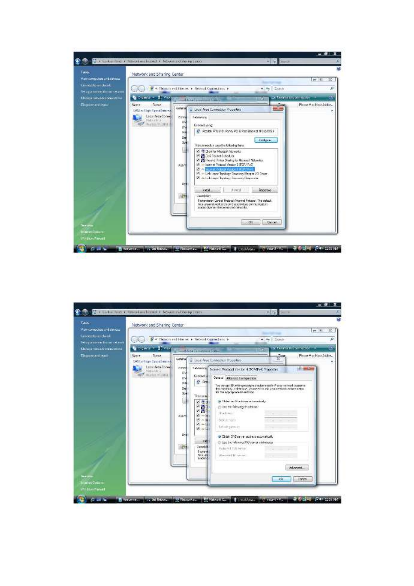
16
4. Select Internet Protocol Version 4 (TCP/IPv4) and click Properties.
5. Select the Obtain an IP address automatically and the Obtain DNS server address
automatically radio buttons.
6. Click OK to finish the configuration.

17
Configuring PC in Windows XP
1. Go to Start / Control Panel (in Classic View). In the Control Panel, double-click on
Network Connections
2. Double-click Local Area Connection.
3. In the Local Area Connection Status window, click Properties.

18
4. Select Internet Protocol (TCP/IP) and click Properties.
5. Select the Obtain an IP address automatically and the Obtain DNS server address
automatically radio buttons.
6. Click OK to finish the configuration.

19
Configuring PC in Windows 2000
1. Go to Start / Settings / Control Panel. In the Control Panel, double-click on Network
and Dial-up Connections.
2. Double-click Local Area Connection.
3. In the Local Area Connection Status window click Properties.
4. Select Internet Protocol (TCP/IP) and click Properties.
5. Select the Obtain an IP address automatically and the Obtain DNS server address
automatically radio buttons.
6. Click OK to finish the configuration.

21
2.4 Configuring with Web Browser
It is advisable to change the administrator password to safeguard the security of your
network. To configure the router, open your browser, type “http: //192.168.1.1” into the
address bar and click “Go” to get to the login page.
Save this address in your Favorites for future reference.
At the User name and Password prompt, type your proper user name and password to
login. The default user name / password are “admin / admin”. You can change these later
if you wish. Click “OK”.

22
If the user name and password are correct, you will login Fiber Router successfully and see
the status page. Now you can configure the Fiber Router for your needs.

24
3.1 Operation Mode
The Fiber Router supports three operation modes – Router, Bridge and WISP (WISP mode
is only supported for wireless fiber router). Currently, it comes pre-configured with
Router mode. Note that, routing mode and bridging mode cannot be used simultaneously.
For Bridge mode, all interfaces are bridged into a single bridge interface.
For Router mode, the Fiber port is treated as WAN port. The other interfaces are bridged
together and are treated as LAN ports.
For WISP Mode (For wireless model), all the Ethernet ports are bridged together and the
wireless interface of this router will connect to ISP’s Access Point. The NAT is enabled and
PCs in Ethernet ports share the same IP to ISP through wireless LAN. The connection type
can be setup in WAN page by using PPPoE, DHCP client, PPTP/L2TP client or static IP.
If you select Bridge operation mode, WAN configuration in Internet Settings are not
available. (Firewall functions on the left page are not available.)
After finishing setting, click Apply to save the settings and make the new configuration take
effect. Click Cancel to close without saving.

25
3.2 Internet Settings
3.2.1 WAN
The WAN Settings screen allows you to specify the type of Internet connection. The WAN
settings offer the following selections for the router’s WAN port, STATIC (fixed IP), DHCP
(Auto config), PPPoE, L2TP, and PPTP.
¾ STATIC (FIXED IP)
Select STATIC (fixed IP) in the WAN Connection Type drop-down list and the following
page appears.
26
Static Mode
IP Address: Enter the IP address of WAN port.
Subnet Mask: Enter IP subnet mask of WAN port.
Default Gateway: Enter the default gateway address of WAN port.
Primary DNS Server: Primary DNS Server f of WAN port.
Secondary DNS Server: Secondary DNS Server of WAN port.
MAC Clone
MAC Clone provides WAN to connect to a MAC address.
Enabled: Enable or disable MAC clone.
After finishing setting, click Apply to save the settings and make the new configuration
take effect.
Click Cancel to close without saving.
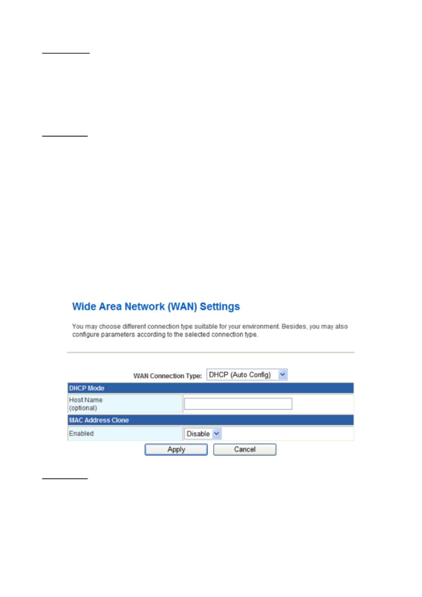
¾ DHCP (AUTO CONFIG)
Select DHCP (Auto config) in the WAN Connection Type drop-down list and the
following page appears. If the WAN connection type is set to DHCP, the device
automatically obtains the IP address, gateway and DNS address from the DHCP server
on WAN interface.
MAC Clone
MAC Clone provides WAN to connect to a MAC address.
Enabled: Enable or disable MAC clone.
After finishing setting, click Apply to save the settings and make the new configuration
take effect.
Click Cancel to close without saving.
27
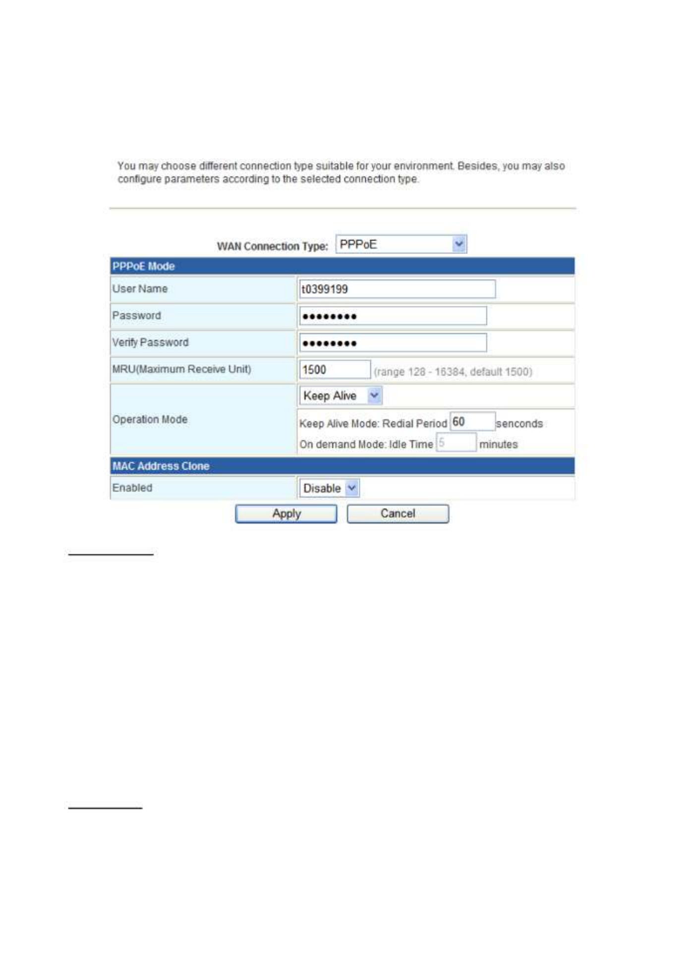
¾ PPPOE
Select PPPoE (ADSL) in the WAN Connection Type drop-down list and the following
page appears. If the WAN connection type is set to PPPoE, you can configure the
following parameters to PPPoE dial up.
PPPoE Mode
User Name: User name of PPPoE account
Password: Password of PPPoE account
Verify Password: Enter the password of PPPoE account again.
Operation Mode: It provides two types of operation modes.
Keep Alive means keeping on-line mode. You can set the redial period in the field.
When the redial period expires, Router will execute dial-up again to keep online.
On Demand means executing dial-up on demand. Within the preset idle time, if
Router does not detect the flow of the user continuously, Router automatically
stops the PPPOE connection. Once it detects the flow (e.g., accessing a
webpage), the router restarts the PPPOE dial-up.
MAC Clone
Enabled: Enable or disable.
After finishing setting, click Apply to save the settings and make the new configuration
take effect.
Click Cancel to close without saving.

29
L2TP Mode
Server IP: Address of L2TP server.
User Name: The user name of L2TP account.
Password: The password of L2TP account.
IP Address: IP address of WAN port.
Subnet Mask: Subnet mask of WAN port.
Default Gateway: The default gate way of WAN port.
Operation Mode: It provides two types of operation modes.
Keep Alive means keeping on-line mode. You can set the redial period in the field.
When the redial period expires, Router will execute dial-up again to keep online.
On Demand means executing dial-up on demand. Within the preset idle time, if
Router does not detect the flow of the user continuously, Router automatically
stops the PPPOE connection. Once it detects the flow (e.g., accessing a
webpage), the router restarts the PPPOE dial-up.
MAC Clone
Enabled: Enable or disable.
After finishing setting, click Apply to save the settings and make the new configuration
take effect.
Click Cancel to close without saving.

30
¾ PPTP
Select PPTP in the WAN Connection Type drop-down list and the following page
appears. There are two address modes: Static and Dynamic.
PPTP Mode
Server IP: Address of PPTP server.
User Name: The user name of PPTP account.
Password: The password of PPTP account.
IP Address: IP address of WAN port.
Subnet Mask: Subnet mask of WAN port.
Default Gateway: The default gate way of WAN port.
Operation Mode: It provides two types of operation modes.
Keep Alive means keeping on-line mode. You can set the redial period in the field.
When the redial period expires, Router will execute dial-up again to keep online.
On Demand means executing dial-up on demand. Within the preset idle time, if
Router does not detect the flow of the user continuously, Router automatically
stops the PPPOE connection. Once it detects the flow (e.g., accessing a
webpage), the router restarts the PPPOE dial-up.
MAC Clone
Enabled: Enable or disable.
After finishing setting, click Apply to save the settings and make the new configuration
take effect.
Click Cancel to close without saving.

32
Primary DNS Server: The primary DNS server address.
Secondary DNS Server: The secondary DNS Server address.
Default Gateway: The default gateway that DHCP server assigns.
Lease Time: Lease time of the IP address.
Statically Assigned: Assign IP to the assigned MAC address. Enter the assigned
MAC address and IP in the corresponding fields.
802.1d Spanning Tree: Spanning Tree Protocol. You can select Enable or Disable.
IGMP Proxy: You can select Enable or Disable.
UPNP: Universal Plug and Play (UPNP).You can select Enable or Disable.
Router Advertisement: You can select Enable or Disable.
DNS Proxy: You can select Enable or Disable.
After finishing setting, click Apply to save the settings and make the new configuration
take effect.
Click Cancel to close without saving.
3.2.3 DHCP clients
You can view the information about DHCP clients in the page.

33
3.2.4 Advanced Routing
You can add or delete routing rules, enable or disable dynamic routing protocol in the page.
Add a routing rule
Destination: Enter the legal destination IP address.
Range: Destination IP address is a host address or the network address.
Gateway: Enter the specific gateway.
Interface: The interface for this route. You can select LAN, WAN and Custom.
Comment: Add the description of this route.
After finishing the setting above, click Apply to make the new routing rule take effect.
Otherwise, click Reset to cancel the new routing rule.
Current Routing table in the system
You can delete or reset the routing rules.
Dynamic Routing Settings
You can enable or disable the RIP.
After finishing the setting above, click Apply to make the new routing rule take effect.
Otherwise, click Reset to cancel the new routing rule.

34
3.2.5 QoS
You may set up rules to provide Quality of Service (QoS) guarantee for some specific
applications. In the page, you can enable or disable Quality of Service. After enabling QoS,
you can set upload bandwidth and download bandwidth.
Upload Bandwidth: You can select the proper bandwidth in the drop-down list. The
value is from 64K to 60M. You can also set the bandwidth by selecting User defined
and enter the proper bandwidth in the field.
Download Bandwidth: You can select the proper bandwidth in the drop-down list.
The value is from 64K to 60M. You can also set the bandwidth by select User defined
and enter the proper bandwidth in the field.
After finishing the setting above, click Submit to save the new configuration.

35
3.3 Wireless Setting (For FRT-401N / 401NS15 / 405N)
3.3.1 Basic
You can configure the minimum number of wireless settings for communication, such as
network name (SSID) and channel.
Wireless Network
Radio On/Off: Enable or disable the wireless LAN.
Network Mode: There are 6 modes: 11b only, 11g only, 11n only, 11b/g mixed, and
11b/g/n mixed mode.
Network Name (SSID): The service set identification (SSID) is a unique name to
identify the router in the wireless LAN. Wireless stations associating to the router
must have the same SSID. Enter a descriptive name. Its length is up to 32 characters.
Multiple SSID 1/2/3/4/5: There are 5 multiple SSIDs. Enter their descriptive names
that you want to use.
Broadcast Network Name (SSID): Select Enable to allow the SSID broadcast on
the network, so that the STA can find it. Otherwise, the STA can not find it.
AP Isolation: Enable or disable AP Isolation. When many clients connect to the same
access point, they can access each other. If you want to disable the access between
clients which connect the same access point, you can enable this function.
MBSSID AP Isolation: Enable or disable MBSSID AP Isolation.
BSSID: Basic Service Set Identifier. This is the assigned MAC address of the station
in the access point. This unique identifier is in Hex format and can only be edited
when Multi BSSID is enabled in the previous screen.

36
Frequency (Channel): A channel is the radio frequency used by wireless device.
Channels available depend on your geographical area. You may have a choice of
channels (for your region) and you should use a different channel from an adjacent
AP to reduce the interference. The Interference and degrading performance occurs
when radio signals from different APs overlap.
HT Physical Mode
HT Physical Mode
Operation Mode: Select Mixed Mode or Green Field.
Channel Bandwidth: Select 20 or 20/40.
Guard Interval: Select Long or Auto.
MCS: Select the proper value between 0 and15 or 32. Auto is the default value.
Reverse Direction Grant (RDG): Select Disable or Enable.
Extension Channel: Select the proper extension channel in the drop-down list.
Aggregation MSDU (A-MSDU): Select Disable or Enable.
Auto Block ACK: Select Disable or Enable.
Decline BA Request: Select Disable or Enable.

39
3.3.3 Security
Choose Wireless Settings>Security and the following page appears. It allows you to
modify the settings to prevent the unauthorized accesses.
Select SSID
SSID choice: Select SSID in the drop-down list.
Security
Security Mode: There are 11 options, including Disable, OPEN, SHARED, WEPAUTO,
WPA, WPA-PSK, WPA2, WPA2-PSK, WPAPSKWPA2PSK, WPA1WPA2, and 802.1X.
[EXAMPLE]
Take 802.1x for example. Select 802.1x in the Security Mode down-list. The page shown
in the following page appears.

40
WEP: Disable or enable WEP.
Radius Server
IP Address: Enter the IP address of Radius Server.
Port: The default port of the RADIUS server for authentication is 1812. You need not
change this value unless your network administrator instructs you to do so with
additional information.
Shared Secret: Enter a password as the key to be shared between the external
authentication server and the access point. The key is not send over the network.
This key must be the same on the external authentication server and your router.
Session Timeout: Set the time interval for session. Enter the proper value in the
field.
Idle Timeout: Set the idle time interval. Enter the proper value in the field.
Access Policy
Policy: There are three options, including Disable, Allow, and Reject. You can choose
Disable, Allow or Reject. Select Allow, only the clients whose MAC address is listed
can access the router. Select Reject, the clients whose MAC address is listed are
denied to access the router.
Add a station MAC: If you want to add a station MAC, enter the MAC address of the
wireless station that are allowed or denied access to your router in this address field.
After finishing the settings above, click to save the settings and make the new Apply
configuration take effect. Click Cancel to close without saving.

41
3.3.4 WDS
Wireless Distribution System (WDS)
WDS Mode: There are four options, including Disable, Lazy Mode, Bridge Mode, and
Repeater Mode.
¾ Disable
Select Disable to disable the WDS mode.
¾ Lazy Mode
WDS Mode: Select Lazy Mode. The FRT-40xN WDS Lazy mode is allowed the other
FRT-40xN WDS bridge / repeater mode link automatically.
Phy Mode: It provides 4 options, including CCK, OFDM, HTMIX, and GREENFIELD.
Encryp Type: It provides 4 options, including None, WEP, TKIP, and AES.
¾ Bridge Mode/ Repeater Mode
WDS Mode: Select Mode orBridge Repeater Mode.
Phy Mode: It provides 4 options, including CCK, OFDM, HTMIX, and GREENFIELD.
Encryp Type: It provides 4 options, including None, WEP, TKIP, and AES.
AP MAC Address: It provides 4 AP MAC Address. Enter the MAC address of the
other APs.

42
WDS (Wireless Distribution System) allows access points to communicate with one
another wirelessly in a standardized way. It can also simplify the network infrastructure by
reducing the amount of cabling required. Basically the access points will act as a client
and an access point at the same time.
WDS is incompatible with WPA. Both features cannot be used at the same time. A WDS
link is bi-directional, so the AP must know the MAC address of the other AP, and the other
AP must have a WDS link back to the AP.
Dynamically assigned and rotated encryption key are not supported in a WDS connection.
This means that WPA and other dynamic key assignment technologies may not be used.
Only Static WEP keys may be used in a WDS connection, including any STAs that are
associated with a WDS repeating AP.
Enter the MAC address of the other APs that you want to link to and click enable.
Supports up to 4 point to multipoint WDS links, check Enable WDS and then enable on
the MAC addresses.
Example of a WDS topology:
AP1 <-- WDS --> Master AP (our AP) <-- WDS --> AP3<-- WDS --> AP4

43
3.3.5 WPS
You can enable or disable the WPS function in this page.
Select Enable in the WPS drop-down list. Click Apply and the following page appear.
WPS Summary
It displays the WPS information, such as WPS Current Status, WPS Configured, and
WPS SSID.
Reset OOB: Reset to out of box (OoB) configuration
WPS Progress
WPS mode: There are two way for you to enable WPS function: PIN, PBC. You can
use a push button configuration (PBC) on the Wi-Fi router. If there is no button, enter
a 4- or 8-digit PIN code. Each STA supporting WPS comes with a hard-coded PIN
code.
PIN: If you select PIN mode, you need enter the PIN number in the field.
WPS Status
It displays the information about WPS status.

44
3.3.6 Station List
Through this page, you can easily identify the connected wireless stations. It automatically
observes the ID of connected wireless station (if specified), MAC address, SSID, and
current status.
45
3.4 Firewall
The Fiber Router provides the fully firewall functions, such as IP/Port/MAC Filtering, Port
Forwarding, DMZ, SPI Firewall and Content Filtering. It serves as an Internet firewall to
protect your network from being accessed by outside users.
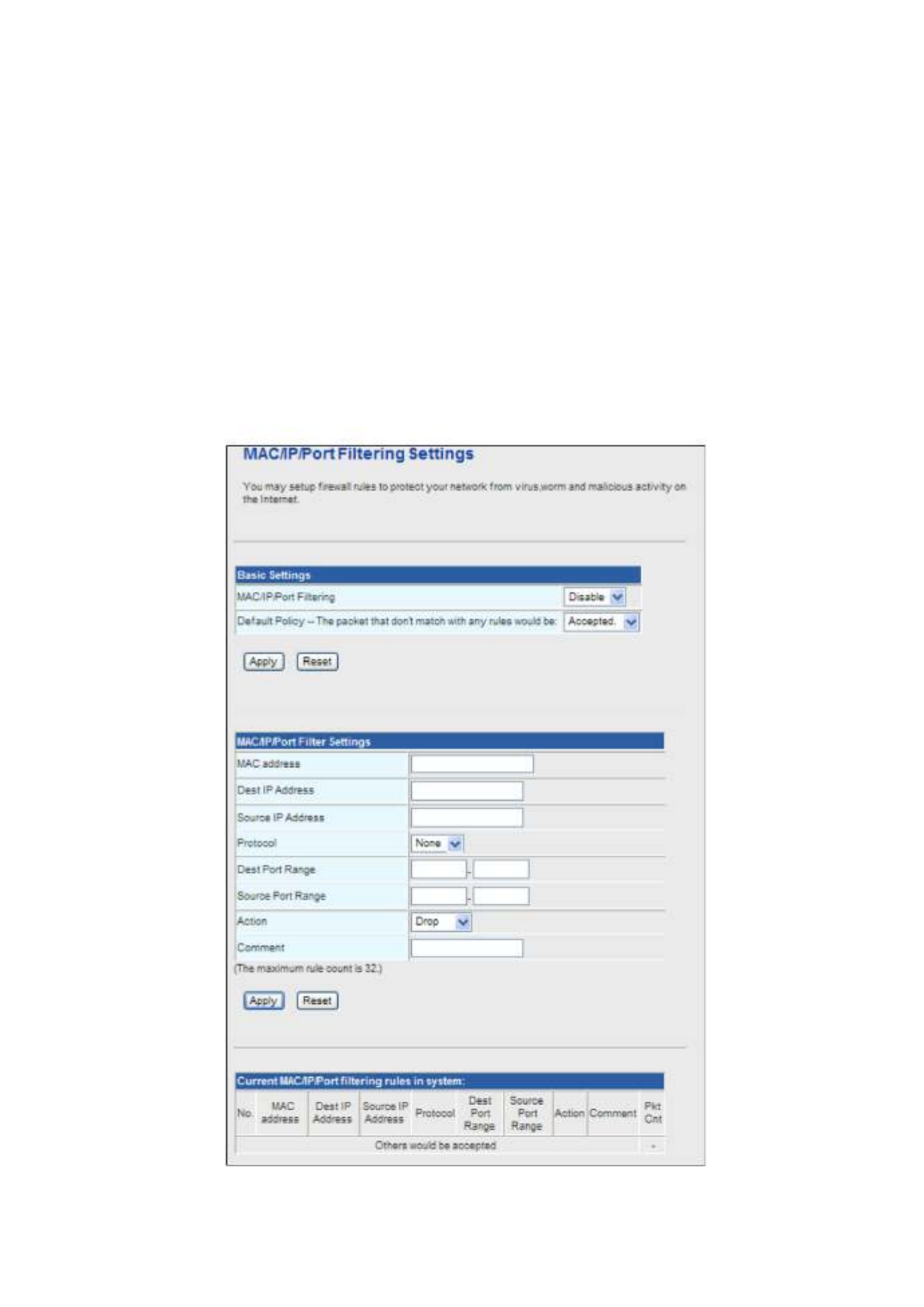
3.4.1 MAC/IP/Port Filtering
Use the MAC/IP/Port filters to deny / allow particular LAN IP addresses from accessing the
Internet. You can deny / allow specific port numbers or all ports for a specific IP address.
You may set up firewall rules to protect your network from malicious activity on the Internet.
It is also convenient for you to delete these settings.
47
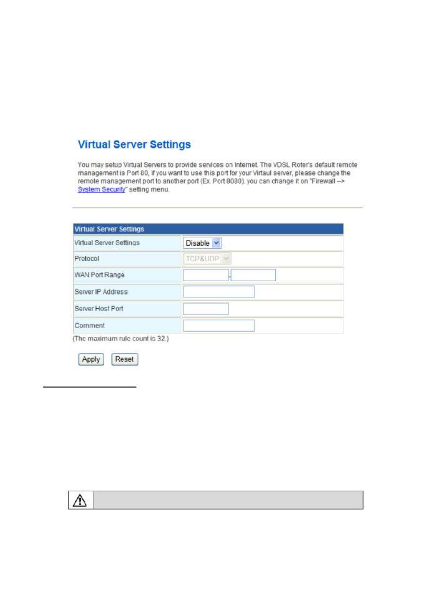
3.4.2 Port Forwarding (Virtual Server)
The Virtual Server is the server or server(s) behind NAT (on the LAN), for example, Web
server or FTP server, that you can make visible to the outside world even though NAT
makes your whole inside network appear as a single machine to the outside world.
This page allows you to set virtual server to provide services on the Internet.
Virtual Server Settings
Virtual Server Settings: Enable or disable this function. After selecting Enable, you
can set the following parameters.
Protocol: There are 3 options, including none, TCP& UDP, TCP, and UDP.
WAN Port Range: You can setup your port range for your WAN side.
Server IP Address: Enter the virtual server IP address in internal network.
Server Host Port: Set the port range of your virtual server.
Comment: Add description for this rule.
The maximal rule number you can add is 32.
Click Apply to make the configuration take effect. Click Reset to cancel the new
configuration.

48
3.4.3 DMZ
DMZ (Demilitarized Zone) allows a single computer on your LAN to expose ALL of its ports
to the Internet. Enter the IP address of that computer as a DMZ (Demilitarized Zone) host
with unrestricted Internet access. When doing this, the DMZ host is no longer behind the
firewall.
This page allows you to set a De-militarized Zone (DMZ) to separate internal network and
Internet.
DMZ Settings: Enable or disable this function. After selecting Enable, you can set the
DMZ IP address.
DMZ IP Address: Enter the DMZ host IP address.
Click Apply to make the configuration take effect. Click Reset to cancel the new
configuration.

50
3.4.5 Content Filtering
This page is used to configure the Blocked URL (Such as tw.yahoo.com) and filtered
keyword. Here you can add / delete URL and filtered keyword.
Choose Firewall > Content Filtering and the following page appears. You can set content
filter to restrict the improper content access.
Webs Content Filters: If you want to block some applications as Proxy, Java and ActiveX
of web pages please select the check box and click “Apply”.
Current Webs URL Filters: If you want to delete some filters in the table above, select
the rules, and then click Delete. Otherwise, click Reset.
Add a URL filter
URL: Enter the URL String and click “Add” to apply this URL filter rule.
Click Add to add a URL filter. Otherwise, click Reset to cancel the URL filter.
The URL Filter allows you to block access to undesirable Web site
To use this feature, you must define "filter strings". If the "filter string" appears in a
requested URL, the request is blocked.

51
3.5 Fiber / OAM Setting
3.5.1 Fiber Configuration
This function allows displaying the Fiber port’s status, Mode, Flow Control and Rate limit.
The Link Status in the screen displays the current connection speed and duplex mode.
• Flow Control Allow Enable or Disable flow control for selected port.
• Enable – 802.3x flow control is enabled on Full-Duplex mode or
Backpressure is enabled on Half-Duplex mode
• Disable – No flow control or backpressure function on no matter
Full-Duplex or Half-Duplex mode
Default value: Disable
• Ingress Rate Limit The value of inbound traffic limitation in kilobit-per-second (kbps). The
possible values are :
• No Limit
• 512K
• 1M
• 2M
• 4M
• 8M
• 10M
• 50M
Default value: No Limit
• Egress Shaping The value of outbound traffic limitation in kilobit-per-second (kbps). The
possible values are :
• No Limit
• 512K
• 1M
• 2M
• 4M
• 8M
• 10M
• 50M
Default value : No Limit

53
2. Reset: Click the “Reset” button to reboot the remote device.
3. Factory: Click the “Factory” button to restore the default settings of remote device.
Remote Port Configuration
The users can manage the remote port from local Fiber Router; you can setup the Port
Mode, Flow Control, Rate Limit for remote device.

54
3.5.3 OAM Configuration
802.3ah OAM Configuration
When enable 802.3ah OAM function, all 802.3ah OAMPDU packets will trap to embedded
CPU. Software will implement auto discovery procedure. With hardware support, software
controls the 802.3ah remote loop back procedure. Hardware can also detect dying gasp
even and interrupt CPU to send dying gasp even notification OAMPDU. All other functions
defined by 802.3ah are implemented using embedded CPU.
When remote device is in loop back mode, hardware can support change looped test
frame’s DA, SA or both as user defined. Hardware can also set to don't change looped test
frame.
This function provides 802.3ah Setup of Managed Media Converter. Press the “Apply”
button to save the current configuration of Managed Media Converter. Below Figure and
Table describes the 802.3ah Setup object of Managed Media Converter.
The 802.3ah OAM Configuration Web page includes the following configurable data:
802.3ah OAM State Provide disable or enable the 802.3ah OAM State function.
Default mode is Enable.
802.3ah OAM Mode Allow to choose “Active” or “Passive” for 802.3ah OAM Mode.
Loopback Reply Provide disable or enable the Loopback Reply function. Default
mode is Enable.
Remote OAM
Configure
Provide disable or enable the Remote OAM Configure function.
Default mode is Enable.
Remote OAM
Configuration Result
Display the Remote OAM Configuration Result.
Apply button Press this button for save current configuration of Managed
Media Converter.
Table Descriptions of the 802.3ah Setup Web Page Screen Objects

55
Local TS-1000 OAM Configuration
Local TS-1000 OAM Setup
This function provides Local TS-1000 OAM Setup of Managed Media Converter. Press the
“Apply” button to save the current configuration of Managed Media Converter. The below
screen and Table describes the Local TS-1000 OAM Setup object of Managed Media
Converter.
Figure Local TS-1000 OAM Setup Web Page screen
The Local TS-1000 OAM Setup Web page includes the following configurable data:
TS-1000 OAM State Provide disable or enable the TS-1000 OAM operation mode.
TS-1000 Mode Provide two TS-1000 modes for operation, the available options
are:
Terminal
Center
Link Transparent Provide disable or enable the Link Transparent function. Default
mode is Disable.
Link Transparent
Result
Display the link transparent result.
Apply button Press this button for save current configuration of Managed Media
Converter.
Table Descriptions of the Local TS-1000 OAM Setup Web Page Screen Objects
#Notice:
The TS-1000 OAM function must work with manageable device
that supports TS-1000 OAM function.

56
3.5.4 Loop back test
802.3ah Loop Back Test
The 802.3ah Loop Back Test allows manual run this loop back test to check the
interconnection between two devices. To assure the Remote 802.3ah function can work
correctly.
This function provides 802.3ah Loop Back Test of Fiber devices. Press the “Apply” button
to run 802.3ah Loop Back Test and see the 802.3ah Loop Back Test Result of Fiber devices.
The below screen and Table describes the 802.3ah Loop Back Test object of Fiber Router.
Figure 802.3ah Loop Back Test Web Page screen

57
The 802.3ah Loop Back Test Web page includes the following configurable data:
802.3ah Loop Back Test
Send Packet Number Allow input the number for packet send and the available options
is 1 to 255. Default is 16.
Packet Length (Not
include CRC)
Allow input the number for Packet Length and the available
options is 60 to 1514. Default is 60.
Apply button Press this button for save current configuration of Fiber Router.
802.3ah Loop Back Test Result
Result Display the 802.3ah Loop Back Test Result. Fail or Pass.
Table Descriptions of the 802.3ah Loop Back Test Web Page Screen Objects
#Notice:
The 802.3ah function must work with manageable device that
supports 802.3ah function.
TS-1000 Loop Back Test
The TS-1000 Loop Back Test allows manual run this loop back test to check the
interconnection between two Fiber devices. To assure the Remote TS-1000 OAM function
can work correctly.

58
In-band and out-band Loop back
This function provides TS-1000 Loop Back Test of Fiber devices. Press the “Apply” button
to run Loop Back Test and see the TS-1000 Loop Back Test Result of Fiber Route. The
below screen and Table describes the TS-1000 Loop Back Test object of Managed Media
Converter.
Figure Remote TS-1000 Loop Back Test Web Page screen
The TS-1000 Loop Back Test Web page includes the following configurable data:
TS-1000 Loop Back Test
Send Packet
Number Allow input the number for packet send and the available
options is 1 to 255. Default is 16.
Apply button Press this button for save current configuration of Fiber Router.
TS-1000 Loop Back Test Result
Result Display the TS-1000 Loop Back Test Result. Fail or Pass.
Result counter Display the value of Counter Result.
Table Descriptions of the TS-1000 Loop Back Test Web Page Screen Objects
#Notice:
The TS-1000 OAM function must work with manageable device
that supports TS-1000 OAM function.

59
3.6 Administration
You can configure admin management in this part. It includes Management, Update
Firmware, Setting management, Reboot, Status, Statistics and System Log.
3.6.1 Management
Choose Administration > Management, and the following page appears. You may
configure administrator account and password, NTP settings, and dynamic DNS settings in
the page.
Administrator Settings
Account: Enter the username of the administrator in the field.
Password: Enter the password of the administrator in the field.
NTP Settings
Current Time: Display the current date and time. Click Sync with host, the current
time is synchronized by your PC which is connected to Router.

60
Time Zone: Select the proper time zone in the drop-down list.
NTP Server: Enter the IP address or domain name of NTP server.
NTP Synchronization (hours): Enter the time interval for synchronization.
DDNS Settings
Dynamic DNS Provider: Select the proper dynamic DNS provider in the drop-down
list. After selecting a dynamic DNS provider, you are allowed to set the following
parameters.
Account: Enter the username of DDNS provider in the field.
Password: Enter the password of DDNS provider in the field.
DDNS: Enter the domain name of your device.
Click Apply to make the configuration take effect. Click Cancel to cancel the new
configuration.
3.6.2 Upload Firmware
Choose Administration > Upload Firmware and the following page appears. In this page,
you may upgrade the correct new version firmware to obtain new functionality. It takes
about 1 minute to upload upgrade flash.
If the firmware is uploaded in an improper way, the system would
core dump.
Update Firmware
Location: Click Browse to select the firmware file, and click Apply to upgrade the
firmware.

61
3.6.3 Setting Management
Choose Administration > Settings Management and the following page appears. You
may save system settings by exporting them to a configuration file, restore them by
importing the file, or reset them to the factory default.
Export Settings
Export Button: Click the Export to export the settings.
Import Settings
Settings file location: Click Browse to select the configuration file, and then click Import
to upload the configuration file. Click Cancel to cancel the uploading operation.
Load Factory Defaults
Load Default Button: Click Load Default to make Router return to the default settings.

62
3.6.4 Reboot
The Reboot screen allows you to restart your router with its current settings. Click the
“Reboot” button and the device will restart.
3.6.5 Status
Choose Administration > Status and the following page appears. It displays the
information about Router status, including system information, Internet configurations, and
local network.

63
3.6.6 Statistics
You can see the Statistic information in this screen. It includes the Traffic for all interfaces.
64
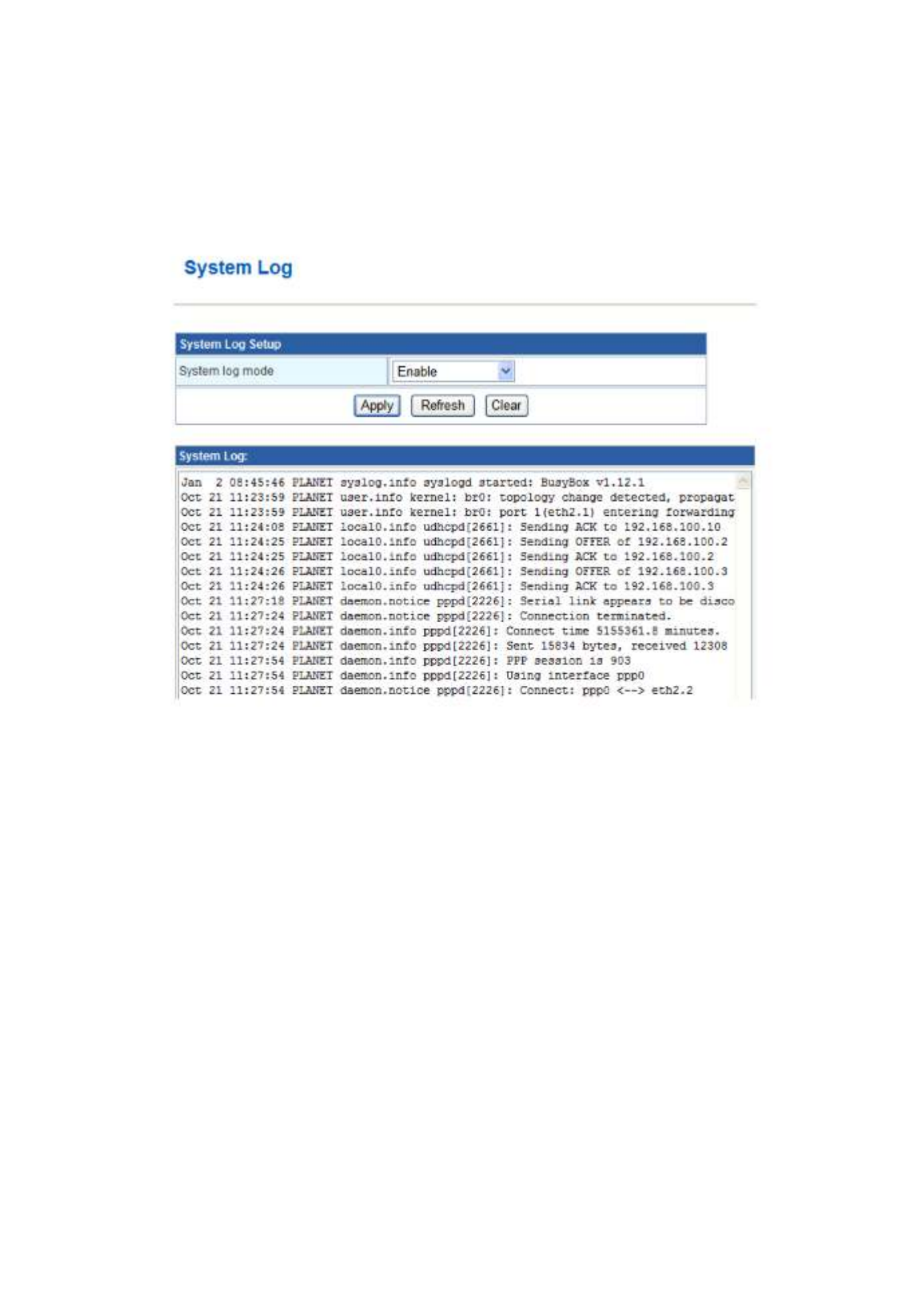
3.6.7 System Log
The system log dialog allows you to view t he “Refresh” button to he system log and click t
fresh the system event logs. Choose Administration > System Log and the following
page appears. You are allowed to view and disable / enable the system log in this page.
Click Refresh to refresh the log. Click Clear to clear the log.

65
Appendix A
A.1 Device‘s RJ-45 Pin Assignments
■
10/100Mbps, 10/100Base-TX
Contact MDI MDI-X
1 1 (TX +) 3
2 2 (TX -) 6
3 3 (RX +) 1
6
6 (RX -)
2
4, 5, 7, 8
Not used
Not used
Implicit implementation of the crossover function within a twisted-pair cable, or at a wiring
panel, while not expressly forbidden, is beyond the scope of this standard.
A.2 RJ-45 cable pin assignment
2 1 3 6
1 2
3
6
2 1 3 6
There are 8 wires on a standard UTP/STP cable and each wire is color-coded. The following shows the pin
allocation and color of straight cable and crossover cable connection:
Figure A-1: Straight-Through and Crossover Cable
Please make sure your connected cables are with same pin assignment and color as above picture before
deploying the cables into your network.

66
A.3 Fiber Optical Cable Connection Parameter
The wiring details are as below:
■
Fiber Optical patch Cables:
Standard Fiber Type Cable Specication
100Base-FX
(1300nm)
Multi-mode 50/125μm or 62.5/125μm
Multi-mode 50/125μm or 62.5/125μm 100Base-FX
(1310nm) Single-mode 9/125μm
100Base-BX-U
(TX :1310/RX :1550)
100Base-BX-D
(TX :1550/RX :1310)
Single-mode 9/125μm
A.4 Available Modules
The following list the available Modules for FRT-40x / 40xN
MFB-FX SFP-Port 100Base-FX Transceiver (1310nm) -2km
MFB-F20 SFP-Port 100Base-FX Transceiver (1310nm) - 20km
MFB-FA20 SFP-Port 100Base-BX Transceiver (WDM,TX:1310nm) -20km
MFB-FB20 SFP-Port 100Base-BX Transceiver (WDM,TX:1550nm) -20km

67
Appendix B: Specification
FRT-401 / FRT-401S15 / FRT-405
Product Internet Fiber Router
Model FRT-401 FRT-401S15 FRT-405
WAN 1 x 100Base-FX port
Ports LAN 4 x 10/100Base-TX port
Connector SC SFP
Mode Multi-mode Single-mode Vary on module
Optic
Interface
Distance 2km 15km Vary on module
Optic wavelength 850nm 1310nm -
Max. -14 -7 -
Launch Power(dBm) Min. -19.0 -20 -
Receive Sensitivity -34.5 -28 -
Maximum Input power -14 -8 -
Fiber-optic cable
50/125μ μm or 62.5/125 m multi-mode fiber cable, up to 2km.
9/125μm single-mode cable, provide long distance for
15/20/35/50km or longer (very on SFP module)
LED Indicators PWR, Fiber, LAN1-4
Button 1 x RESET button
Software
Max. Sessions 4096
Protocol / Feature Router and Bridge mode
Static Routing and RIPv1/2
DMZ and Virtual Server
802.1D
802.1Q VLAN support
QoS
SNTP
DHCP Server / Client
IGMP Proxy and DNS Proxy
Universal Plug and Play (UPnP) Compliant
DDNS (Dynamic Domain Name System)
VPN VPN Pass-Through
Security Built-in NAT Firewall
MAC / IP/ Port Filtering
Content Filtering
SPI Firewall support
Password protection for system management
Management Web-based configuration
Available Syslog support
TR-069*
SNMP v1/v2c
TS-1000 and 802.3ah OAM support
* Feature Enhance by Future FW upgradeable.
Specyfikacje produktu
| Marka: | Planet |
| Kategoria: | router |
| Model: | FRT-401S15 |
Potrzebujesz pomocy?
Jeśli potrzebujesz pomocy z Planet FRT-401S15, zadaj pytanie poniżej, a inni użytkownicy Ci odpowiedzą
Instrukcje router Planet

3 Października 2024
3 Października 2024
3 Października 2024
3 Października 2024
3 Października 2024
23 Września 2024
28 Sierpnia 2024
19 Sierpnia 2024
19 Sierpnia 2024
19 Sierpnia 2024
Instrukcje router
- router Samsung
- router Tenda
- router AEG
- router Motorola
- router Xiaomi
- router Huawei
- router TCL
- router TP-Link
- router Milwaukee
- router Gigabyte
- router Acer
- router Bosch
- router Hikvision
- router Roland
- router Nokia
- router Toolcraft
- router Festool
- router EZVIZ
- router Conceptronic
- router StarTech.com
- router Asus
- router Medion
- router Black & Decker
- router TRENDnet
- router MSI
- router D-Link
- router ATen
- router Siemens
- router Thrustmaster
- router DeWalt
- router Einhell
- router Alcatel
- router Sigma
- router HP
- router Teltonika
- router Silverline
- router Manhattan
- router Strong
- router Makita
- router Mikrotik
- router Cisco
- router Moxa
- router Synology
- router Gembird
- router ZTE
- router Lindy
- router Zebra
- router ZyXEL
- router Trust
- router LogiLink
- router Dell
- router IFM
- router Linksys
- router Google
- router Digitus
- router Vimar
- router Dahua Technology
- router Schneider
- router Kyocera
- router Sabrent
- router AVMATRIX
- router Renkforce
- router Netgear
- router Thomson
- router AVM
- router BT
- router Totolink
- router Black Box
- router Güde
- router Apple
- router Lancom
- router Zoom
- router Iogear
- router Intellinet
- router Devolo
- router Vtech
- router Mercusys
- router I-TEC
- router Draytek
- router Edimax
- router Razer
- router AirLive
- router EnGenius
- router NEC
- router Blustream
- router LevelOne
- router Digi
- router Milesight
- router Rocstor
- router Hama
- router Ubiquiti Networks
- router Western Digital
- router ModeCom
- router Smart-AVI
- router Barco
- router Sagemcom
- router Juniper
- router Cudy
- router QNAP
- router Arris
- router Netis
- router Anker
- router Allnet
- router Marshall Electronics
- router Hitachi
- router M-life
- router AJA
- router Media-Tech
- router BenQ
- router Atlona
- router FSR
- router Gefen
- router Vivanco
- router Topcom
- router PowerPlus
- router HiKOKI
- router Blackmagic Design
- router Kathrein
- router JUNG
- router Foscam
- router Alfa
- router Porter-Cable
- router Metabo
- router Starlink
- router Keewifi
- router Digital Forecast
- router Keenetic
- router SPL
- router Cotech
- router Skil
- router Alfatron
- router Digitalinx
- router Clas Ohlson
- router KPN
- router Belkin
- router Kramer
- router KanexPro
- router Kopul
- router BZBGear
- router RGBlink
- router Key Digital
- router UPC
- router Lumantek
- router Allied Telesis
- router Actiontec
- router Proximus
- router Eminent
- router Sitecom
- router Sagem
- router Nilox
- router Sonos
- router Patton
- router Techly
- router Envivo
- router Buffalo
- router Nest
- router Vodafone
- router ICIDU
- router Milan
- router Konig
- router AT&T
- router Sweex
- router Aruba
- router Phicomm
- router Kasda
- router Technicolor
- router Verizon
- router Billion
- router T-Mobile
- router RAVPower
- router Hawking Technologies
- router Nexxt
- router WyreStorm
- router Beafon
- router Kraun
- router LTS
- router Zolid
- router Telstra
- router Holzmann
- router SIIG
- router Eero
- router Advantech
- router Mercku
- router Hercules
- router Xantech
- router Intelix
- router MuxLab
- router Pentagram
- router Ocean Matrix
- router Comprehensive
- router Arcadyan
- router Digiconnect
- router Ubee
- router SMC
- router Tele 2
- router Kogan
- router Peak
- router CradlePoint
- router Davolink
- router Sixnet
- router AVPro Edge
- router Evolution
- router 7inova
- router Predator
- router A-NeuVideo
- router United Telecom
- router F-Secure
- router Rosewill
- router Digicom
- router On Networks
- router Wisetiger
- router Leoxsys
- router Readynet
- router OneAccess
- router Accelerated
- router Nexaira
- router Hamlet
- router Approx
- router T-com
- router Amped Wireless
- router Cambium Networks
- router 3Com
- router Avenview
- router Ruckus Wireless
- router Dovado
- router Mach Power
- router EXSYS
- router NetComm
- router Comtrend
- router Premiertek
- router Bea-fon
- router GL.iNet
- router Shinybow
- router Edgewater
- router Atlantis Land
- router Lantronix
- router PulseAudio
- router Luxul
- router DVDO
- router StarIink
- router Silentwind
- router Keezel
- router VigilLink
Najnowsze instrukcje dla router
9 Kwietnia 2025
9 Kwietnia 2025

8 Kwietnia 2025

3 Kwietnia 2025

2 Kwietnia 2025
1 Kwietnia 2025
30 Marca 2025
30 Marca 2025
30 Marca 2025
30 Marca 2025