Instrukcja obsługi Lowrance LMS339C
Lowrance
Radar statku
LMS339C
Przeczytaj poniżej 📖 instrukcję obsługi w języku polskim dla Lowrance LMS339C (204 stron) w kategorii Radar statku. Ta instrukcja była pomocna dla 16 osób i została oceniona przez 2 użytkowników na średnio 4.5 gwiazdek
Strona 1/204
Pub. 988-0152-111
www.lowrance.com
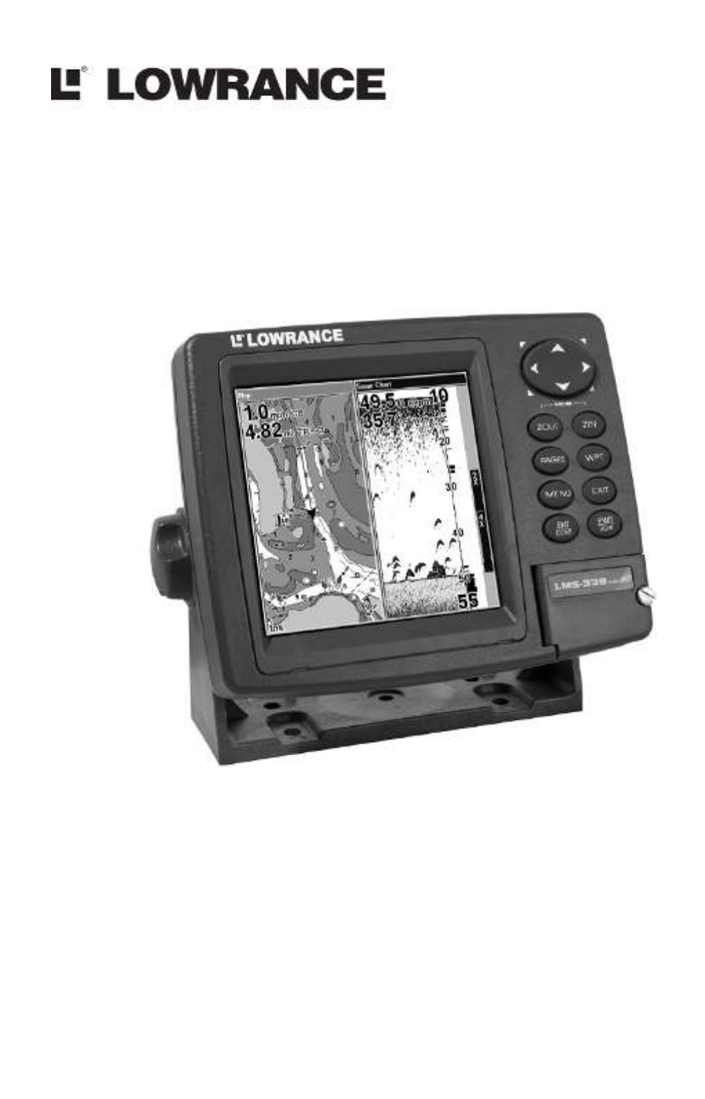
LMS-334c iGPS &
LMS-339cDF iGPS
Fish-finding Sonar & Mapping GPS
Installation and Operation
Instructions

Copyright © 2006 Lowrance Electronics, Inc.
All rights reserved.
No part of this manual may be copied, reproduced, republished, transmitted or
distributed for any purpose, without prior written consent of Lowrance
Electronics. Any unauthorized commercial distribution of this manual is
strictly prohibited.
Lowrance
is a registered trademark of Lowrance Electronics, Inc.
MapCreate, FreedomMaps, IMS and NauticPaths are
trademarks of LEI. Fishing Hot Spots is a registered trademark of
Fishing Hot Spots Inc. Navionics is a registered trademark of
Navionics, Inc.
eXitSource Database, copyright 2001-2005 Zenrin Co.
Ltd. Exit Authority and eXitSource are trademarks of
Zenrin Co. Ltd.
Lowrance Electronics may find it necessary to change or end our
policies, regulations and special offers at any time. We reserve the right
to do so without notice. All features and specifications subject to change
without notice. All screens in this manual are simulated. On the cover:
LMS-339cDF iGPS shown.
For free owner's manuals and other information,
visit our web site:
www.lowrance.com
Lowrance Electronics Inc.
12000 E. Skelly Dr.
Tulsa, OK USA 74128-2486
Printed in USA.

i
Table of Contents
Section 1: Read Me First! ......................................................... 1
Capabilities and Specifications: .................................................... 3
How to use this manual: typographical conventions ................ 10
Arrow Keys.............................................................................. 12
Keyboard ................................................................................. 12
Menu Commands .................................................................... 12
Instructions = Menu Sequences ............................................. 12
Section 2: Installation & Accessories.................................. 13
Preparations................................................................................ 13
Transducer Installation.............................................................. 13
Recommended Tools and Supplies ......................................... 14
Single-frequency transom installations ............................. 14
Dual-frequency transom installations ............................... 14
Single-frequency trolling motor installations.................... 14
Shoot-through hull installations ........................................ 14
Selecting a Transducer Location............................................ 14
How low should you go?.......................................................... 16
Shoot-Thru-Hull vs. Transom Mounting ............................... 16
Transom Transducer Assembly and Mounting ..................... 17
Trolling Motor Bracket Installation (single-frequency only) 22
Transducer Orientation and Fish Arches .............................. 23
Shoot-Thru-Hull Preparation................................................. 24
Testing Determines Best Location......................................... 24
Shoot-Thru-Hull Installation ................................................. 26
Speed/Temperature Sensors................................................. 28
Optional Speed Sensor Installation ....................................... 28
Power Connections...................................................................... 29
Powering a NMEA 2000® Buss .................................................. 30
GPS Internal Antenna................................................................ 32
NMEA 2000 Cable Connections ................................................. 32
Connecting to a NMEA 2000 Network................................... 33
NMEA 0183 Wiring ................................................................ 33
Mounting the Unit: Bracket or Portable.................................... 35
MMC or SD Card Memory Card Installation............................ 38
Other Accessories........................................................................ 39
Face Cover................................................................................... 40
Section 3: Basic Sonar Operation ........................................ 41
Keyboard ..................................................................................... 41
Power/lights on and off ............................................................... 42
Main Menu .................................................................................. 42
Pages ........................................................................................... 43
Satellite Status Page .............................................................. 44
Specyfikacje produktu
| Marka: | Lowrance |
| Kategoria: | Radar statku |
| Model: | LMS339C |
Potrzebujesz pomocy?
Jeśli potrzebujesz pomocy z Lowrance LMS339C, zadaj pytanie poniżej, a inni użytkownicy Ci odpowiedzą
Instrukcje Radar statku Lowrance

20 Września 2024
7 Września 2024
7 Września 2024
1 Września 2024
1 Września 2024
1 Września 2024
31 Sierpnia 2024
30 Sierpnia 2024
28 Sierpnia 2024
23 Sierpnia 2024
Instrukcje Radar statku
- Radar statku Garmin
- Radar statku Navman
- Radar statku Simrad
- Radar statku Raymarine
- Radar statku Furuno
- Radar statku JRC
Najnowsze instrukcje dla Radar statku

8 Października 2024
8 Października 2024
8 Października 2024
8 Października 2024
4 Października 2024
25 Września 2024
23 Września 2024
22 Września 2024
21 Września 2024
16 Września 2024