Instrukcja obsługi Lenovo System x3690 X5
Przeczytaj poniżej 📖 instrukcję obsługi w języku polskim dla Lenovo System x3690 X5 (180 stron) w kategorii serwer. Ta instrukcja była pomocna dla 8 osób i została oceniona przez 2 użytkowników na średnio 4.5 gwiazdek
Strona 1/180

System x3690 X5
Types 7147, 7148, 7149, and 7192
Installation and User's Guide


System x3690 X5
Types 7147, 7148, 7149, and 7192
Installation and User's Guide

Note: Before using this information and the product it supports, read the general information in
“Notices” on page 153 and the , andIBM Safety Information IBM Environmental Notices and User's
Guide Documentation IBM Warranty Informationon the IBM CD, and the document that comes with
the server.
Fifth Edition (May 2011)
© Copyright IBM Corporation 2011.
US Government Users Restricted Rights – Use, duplication or disclosure restricted by GSA ADP Schedule Contract
with IBM Corp.

Contents
Safety . . . . . . . . . . . . . . . v
Chapter 1. The System x3690 X5 Types
7147, 7148, 7149, and 7192 server . . . 1
The IBM Documentation CD . . . . . . . . . 3
Hardware and software requirements . . . . . 3
Using the Documentation Browser . . . . . . 4
Related documentation . . . . . . . . . . . 5
Notices and statements in this document . . . . . 6
Server features and specifications . . . . . . . 7
What your server offers . . . . . . . . . . 10
Reliability, availability, and serviceability . . . . 15
IBM Systems Director . . . . . . . . . . . 16
Server controls, LEDs, and power . . . . . . . 17
Front view. . . . . . . . . . . . . . 17
Operator information panel . . . . . . . . 18
Light path diagnostics panel. . . . . . . . 19
Rear view . . . . . . . . . . . . . . 21
Server power features . . . . . . . . . . 23
Turning on the server . . . . . . . . . 23
Turning off the server . . . . . . . . . 24
IBM MAX5 for System x memory expansion module 25
MAX5 features and specifications . . . . . . 26
What the MAX5 offers. . . . . . . . . . 28
MAX5 reliability, availability, and serviceability
features. . . . . . . . . . . . . . . 28
MAX5 indicators, LEDs, and power . . . . . 29
Front view. . . . . . . . . . . . . 29
Rear view . . . . . . . . . . . . . 30
Turning the MAX5 on and off . . . . . . . 31
Chapter 2. Installing optional devices 33
Installing hardware devices in the server . . . . 34
Instructions for IBM Business Partners . . . . 34
Server components . . . . . . . . . . . 34
System-board internal connectors . . . . . 36
System-board external connectors . . . . . 37
System-board switches and jumpers . . . . 38
System-board LEDs. . . . . . . . . . 40
System-board optional device connectors . . 41
Optional 16-DIMM memory tray . . . . . . 41
PCI riser card with three slots . . . . . . . 42
PCI riser card with two slots . . . . . . . 43
PCI riser card with one slot . . . . . . . . 43
Installation guidelines . . . . . . . . . . 44
System reliability guidelines . . . . . . . 45
Handling static-sensitive devices . . . . . 46
Removing the server top cover . . . . . . . 46
Removing the memory tray . . . . . . . . 47
Removing the DIMM air baffle . . . . . . . 48
Removing the microprocessor air baffle . . . . 49
Removing the fan cage assembly . . . . . . 50
Installing a memory module. . . . . . . . 51
Installing drives . . . . . . . . . . . . 58
Installing 2.5-inch and 1.8-inch hot-swap
drives . . . . . . . . . . . . . . 59
IDs for hot-swap drives . . . . . . . . 61
Supported SAS/SATA drive backplane
configurations . . . . . . . . . . . 62
Installing an optional CD/DVD drive . . . 67
Installing a PCI riser-card assembly . . . . . 69
Installing an adapter . . . . . . . . . . 70
Installing an IBM ServeRAID M1015 SAS/SATA
Controller . . . . . . . . . . . . . . 73
Installing an optional IBM ServeRAID M5015
SAS/SATA Controller . . . . . . . . . . 76
Installing an optional IBM ServeRAID B5015 SSD
Controller . . . . . . . . . . . . . . 79
Installing an optional IBM 4x4 Drive Backplane
ServeRAID Expansion adapter . . . . . . . 82
Installing a second microprocessor and heat sink 85
Thermal grease . . . . . . . . . . . 91
Installing a hot-swap power supply . . . . . 92
Installing the optional power interposer card
assembly . . . . . . . . . . . . . . 94
Installing a USB embedded hypervisor flash
device . . . . . . . . . . . . . . . 95
Installing a RAID adapter battery remotely in the
server . . . . . . . . . . . . . . . 97
Installing the optional simple-swap SATA drive
and backplate assembly . . . . . . . . . 101
Installing the 8x1.8-inch hot-swap drive
backplane assembly . . . . . . . . . . 103
Installing the 8x2.5-inch hot-swap drive
backplane . . . . . . . . . . . . . 106
Installing the 4x2.5-inch hot-swap drive
backplane . . . . . . . . . . . . . 109
Completing the installation . . . . . . . . 112
Replacing the DIMM air baffle. . . . . . 112
Replacing the microprocessor air baffle . . . 113
Replacing the memory tray . . . . . . . 113
Replacing the fan cage assembly . . . . . 114
Replacing the server top cover. . . . . . 115
Connecting the cables . . . . . . . . 116
Updating the server configuration . . . . 117
Installing hardware devices in the MAX5
expansion module . . . . . . . . . . . . 117
MAX5 components . . . . . . . . . . 117
Removing the MAX5 bezel . . . . . . . . 118
Removing the MAX5 system-board tray . . . 119
Installing a MAX5 memory module . . . . . 120
Installing a MAX5 hot-swap power supply . . 125
Completing the MAX5 installation . . . . . 127
Replacing the MAX5 system-board tray . . 127
Replacing the MAX5 bezel . . . . . . . 128
Connecting the MAX5 cables . . . . . . 128
Updating the MAX5 configuration . . . . 129
Chapter 3. Configuring the server . . 131
© Copyright IBM Corp. 2011 iii

Using the Setup utility . . . . . . . . . . 132
Starting the Setup utility . . . . . . . . 132
Setup utility menu choices . . . . . . . . 133
Passwords . . . . . . . . . . . . . 137
Power-on password . . . . . . . . . 137
Administrator password. . . . . . . . 139
Using the Boot Manager program . . . . . . 139
Starting the backup server firmware. . . . . . 139
The Update System Pack InstallerXpress . . . . 140
Using the ServerGuide Setup and Installation CD 140
ServerGuide features . . . . . . . . . . 141
Setup and configuration overview . . . . . 141
Typical operating-system installation . . . . 141
Installing your operating system without using
ServerGuide . . . . . . . . . . . . . 142
Using the integrated management module. . . . 142
Using the embedded hypervisor . . . . . . . 143
Using the remote presence and blue-screen capture
features . . . . . . . . . . . . . . . 145
Obtaining the IP address for the IMM . . . . 145
Logging on to the Web interface . . . . . . 146
Enabling the Broadcom Gigabit Ethernet Utility
program . . . . . . . . . . . . . . . 146
Configuring the Gigabit Ethernet controller . . . 146
Configuring RAID arrays . . . . . . . . . 147
IBM Advanced Settings Utility program . . . . 147
Updating IBM Systems Director . . . . . . . 148
Appendix. Getting help and technical
assistance. . . . . . . . . . . . . 149
Before you call . . . . . . . . . . . . . 149
Using the documentation . . . . . . . . . 150
Getting help and information from the World Wide
Web . . . . . . . . . . . . . . . . 150
Software service and support . . . . . . . . 150
Hardware service and support . . . . . . . 151
IBM Taiwan product service . . . . . . . . 151
Notices . . . . . . . . . . . . . . 153
Trademarks . . . . . . . . . . . . . . 154
Important notes . . . . . . . . . . . . 154
Particulate contamination . . . . . . . . . 155
Documentation format . . . . . . . . . . 156
Electronic emission notices . . . . . . . . . 156
Federal Communications Commission (FCC)
statement. . . . . . . . . . . . . . 156
Industry Canada Class A emission compliance
statement. . . . . . . . . . . . . . 157
Avis de conformité à la réglementation
d'Industrie Canada . . . . . . . . . . 157
Australia and New Zealand Class A statement 157
European Union EMC Directive conformance
statement. . . . . . . . . . . . . . 157
Germany Class A statement . . . . . . . 158
Japan VCCI Class A statement. . . . . . . 159
Japan Electronics and Information Technology
Industries Association (JEITA) statement . . . 159
Korea Communications Commission (KCC)
statement. . . . . . . . . . . . . . 159
Russia Electromagnetic Interference (EMI) Class
A statement . . . . . . . . . . . . . 159
People's Republic of China Class A electronic
emission statement . . . . . . . . . . 160
Taiwan Class A compliance statement . . . . 160
Index . . . . . . . . . . . . . . . 161
iv System x3690 X5 Types 7147, 7148, 7149, and 7192: Installation and User's Guide
Antes de instalar este produto, leia as Informações sobre Segurança.
Antes de instalar este producto, lea la información de seguridad.
Läs säkerhetsinformationen innan du installerar den här produkten.
Important:
Each caution and danger statement in this documentation is labeled with a
number. This number is used to cross reference an English language caution or
danger statement with translated versions of the caution or danger statement in
the document.Safety Information
For example, if a caution statement is labeled Statement 1, translations for that
caution statement are in the document under Statement 1.Safety Information
Be sure to read all caution and danger statements in this document before you
perform the procedures. Read any additional safety information that comes with
the server or optional device before you install the device.
Statement 1
vi System x3690 X5 Types 7147, 7148, 7149, and 7192: Installation and User's Guide

DANGER
Electrical current from power, telephone, and communication cables is
hazardous.
To avoid a shock hazard:
vDo not connect or disconnect any cables or perform installation,
maintenance, or reconfiguration of this product during an electrical storm.
vConnect all power cords to a properly wired and grounded electrical outlet.
vConnect to properly wired outlets any equipment that will be attached to
this product.
vWhen possible, use one hand only to connect or disconnect signal cables.
vNever turn on any equipment when there is evidence of fire, water, or
structural damage.
vDisconnect the attached power cords, telecommunications systems,
networks, and modems before you open the device covers, unless
instructed otherwise in the installation and configuration procedures.
vConnect and disconnect cables as described in the following table when
installing, moving, or opening covers on this product or attached devices.
To Connect: To Disconnect:
1. Turn everything OFF.
2. First, attach all cables to devices.
3. Attach signal cables to connectors.
4. Attach power cords to outlet.
5. Turn device ON.
1. Turn everything OFF.
2. First, remove power cords from outlet.
3. Remove signal cables from connectors.
4. Remove all cables from devices.
Statement 2
CAUTION:
When replacing the lithium battery, use only IBM Part Number 33F8354 or an
equivalent type battery recommended by the manufacturer. If your system has a
module containing a lithium battery, replace it only with the same module type
made by the same manufacturer. The battery contains lithium and can explode if
not properly used, handled, or disposed of.
Do not:
vThrow or immerse into water
vHeat to more than 100°C (212°F)
vRepair or disassemble
Dispose of the battery as required by local ordinances or regulations.
Safety vii

Statement 3
CAUTION:
When laser products (such as CD-ROMs, DVD drives, fiber optic devices, or
transmitters) are installed, note the following:
vDo not remove the covers. Removing the covers of the laser product could
result in exposure to hazardous laser radiation. There are no serviceable parts
inside the device.
vUse of controls or adjustments or performance of procedures other than those
specified herein might result in hazardous radiation exposure.
DANGER
Some laser products contain an embedded Class 3A or Class 3B laser diode.
Note the following.
Laser radiation when open. Do not stare into the beam, do not view directly
with optical instruments, and avoid direct exposure to the beam.
Class 1 Laser Product
Laser Klasse 1
Laser Klass 1
Luokan 1 Laserlaite
Appareil A Laser de Classe 1
`
Statement 4
≥≥≥18 kg (39.7 lb.) 32 kg (70.5 lb.) 55 kg (121.2 lb.)
viii System x3690 X5 Types 7147, 7148, 7149, and 7192: Installation and User's Guide

CAUTION:
Use safe practices when lifting.
Statement 5
CAUTION:
The power control button on the device and the power switch on the power
supply do not turn off the electrical current supplied to the device. The device
also might have more than one power cord. To remove all electrical current from
the device, ensure that all power cords are disconnected from the power source.
1
2
Statement 6
CAUTION:
Do not place any objects on top of a rack-mounted device unless that
rack-mounted device is intended for use as a shelf.
Statement 8
CAUTION:
Never remove the cover on a power supply or any part that has the following
label attached.
Hazardous voltage, current, and energy levels are present inside any component
that has this label attached. There are no serviceable parts inside these
components. If you suspect a problem with one of these parts, contact a service
technician.
Safety ix
Statement 12
CAUTION:
The following label indicates a hot surface nearby.
Statement 26
CAUTION:
Do not place any object on top of rack-mounted devices.
>240VA
Statement 35:
CAUTION:
Hazardous energy present. Voltages with hazardous energy
might cause heating when shorted with metal, which might
result in splattered metal, burns, or both.
This server is suitable for use on an IT power-distribution system whose maximum
phase-to-phase voltage is 240 V under any distribution fault condition.
Important: Maschinenlärminformations-Verordnung - 3. GPSGV, der höchste
Schalldruckpegel beträgt 70 dB(A) oder weniger.
United Kingdom - Notice to Customers:
This apparatus is approved under approval number NS/G/1234/J/100003 for
indirect connection to public telecommunication systems in the United Kingdom.
xSystem x3690 X5 Types 7147, 7148, 7149, and 7192: Installation and User's Guide

Chapter 1. The System x3690 X5 Types 7147, 7148, 7149, and
7192 server
This contains information and instructions for settingInstallation and User's Guide
up your IBM®System x3690 X5 Types 7147, 7148, 7149, and 7192 server,
instructions for installing some optional devices, and instructions for cabling, and
configuring the server. This document also contains information and instructions
for installing options in the optional IBM MAX5 for System x (MAX5) memory
expansion module (see “IBM MAX5 for System x memory expansion module” on
page 25 for more information about the optional MAX5). For removing and
installing optional devices, diagnostics and troubleshooting information, see the
Problem Determination and Service Guide Documentationon the IBM CD, which comes
with the server.
Important: The IBM MAX5 for System x is a Listed Accessory for use with the IBM
System x3690 X5 only.
In addition to the instructions in Chapter 2, “Installing optional devices,” on page
33 for installing optional hardware devices, updating firmware and device drivers,
and completing the installation, IBM Business Partners must also complete the
steps in “Instructions for IBM Business Partners” on page 34.
The IBM System x3690 X5 Types 7147, 7148, 7149, and 7192 server is a 2-U-high
rack model server for virtualization, database, and computational intensive
computing. This high-performance, scalable server is ideally suited for enterprise
environments that require superior input/output (I/O) flexibility, scalability, and
high manageability.
Performance, ease of use, reliability, and expansion capabilities were key
considerations in the design of the server. These design features make it possible
for you to customize the system hardware to meet your needs today and provide
flexible expansion capabilities for the future.
The server comes with a limited warranty. For information about the terms of the
warranty and getting service and assistance, see the IBM Warranty Information
document that comes with the server.
The server contains IBM X-Architecture
®technologies, which help increase
performance and reliability. For more information, see “What your server offers”
on page 10 and “Reliability, availability, and serviceability” on page 15.
You can obtain up-to-date information about the server and other IBM server
products at http://www.ibm.com/systems/x/. At http://www.ibm.com/support/
mysupport/, you can create a personalized support page by identifying IBM
products that are of interest to you. From this personalized page, you can subscribe
to weekly e-mail notifications about new technical documents, search for
information and downloads, and access various administrative services.
If you participate in the IBM client reference program, you can share information
about your use of technology, best practices, and innovative solutions; build a
professional network; and gain visibility for your business. For more information
about the IBM client reference program, see http://www.ibm.com/ibm/
clientreference/.
© Copyright IBM Corp. 2011 1

The server supports up to 24 drives, using the supported drive backplane
configurations. It supports 2.5-inch hot-swap Serial Attached SCSI (SAS) or SATA
hard disk drives, 2.5-inch hot-swap SAS or SATA solid state drives (SSD), or
1.8-inch hot-swap solid state drives. See “Supported SAS/SATA drive backplane
configurations” on page 62 for a complete list of the supported configurations. The
illustrations in this document might differ slightly from your hardware.
The following illustration shows the front of the server.
Rack
release
latch
0 1 2 3 4 5 6 7 8 9 10 11 12 13 14 15
Drive bays
Video
connector
USB 1
connector
USB 2
connector
Operator information
panel release latch
Rack
release
latch
Operator
information
panel
Power-on
button
and LED
Optical drive
activity LED
Optical drive
eject button
Drive activity
LED (green)
Drive status
LED (amber)
Scalability
LED
If firmware and documentation updates are available, you can download them
from the IBM Web site. The server might have features that are not described in
the documentation that comes with the server, and the documentation might be
updated occasionally to include information about those features, or technical
updates might be available to provide additional information that is not included
in the server documentation. To check for updates, go to http://www.ibm.com/
supportportal/.
Record information about the server in the following table.
Product name IBM System x3690 X5 server
Machine type 7147, 7148, 7149, or 7192
Model number _____________________________________________
Serial number _____________________________________________
The model number and serial number are on the ID label on the front of the
server, as shown in the following illustration.
Note: The illustrations in this document might differ slightly from your hardware.
2System x3690 X5 Types 7147, 7148, 7149, and 7192: Installation and User's Guide
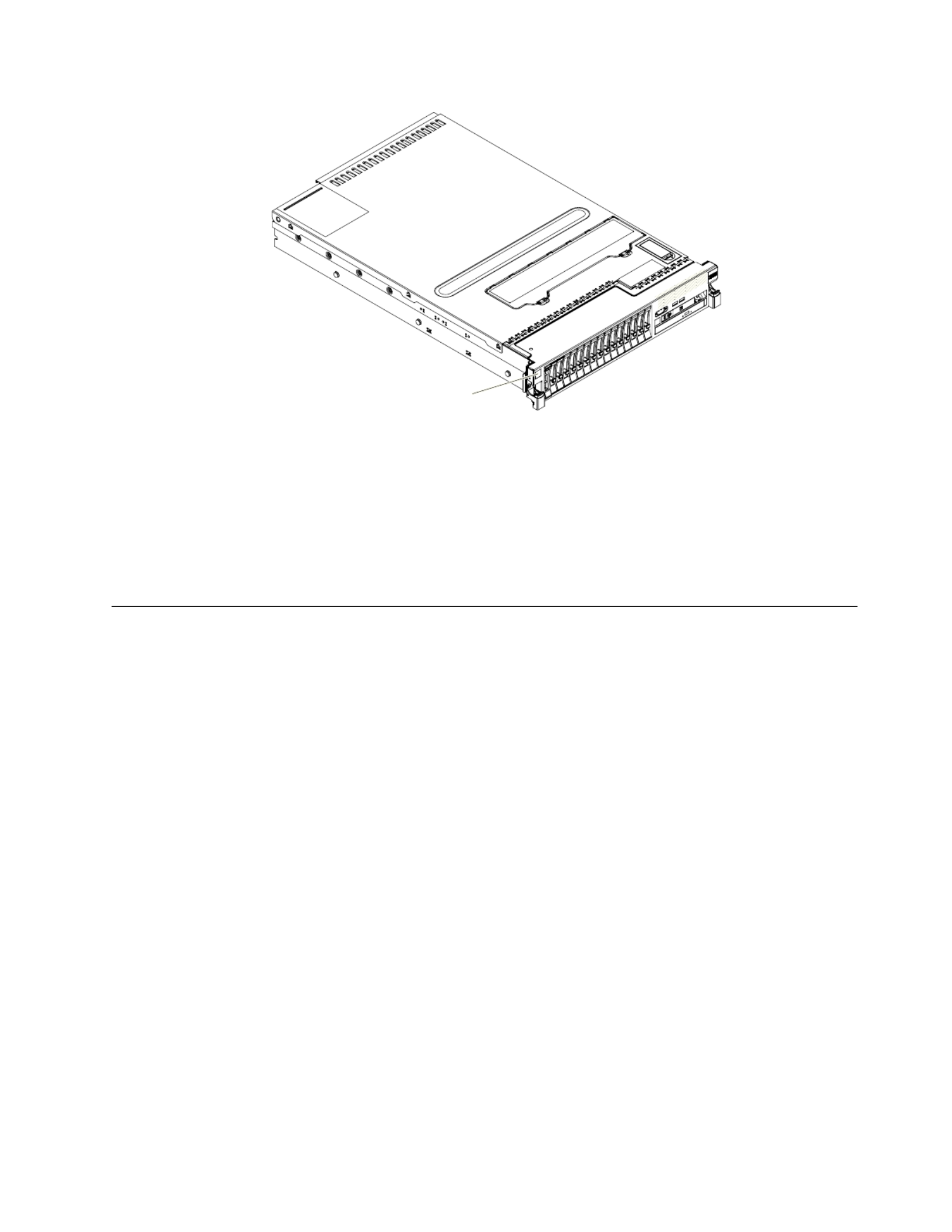
ID label
You can download an IBM CD to help youServerGuide Setup and Installation
configure the hardware, install device drivers, and install the operating system.
For a list of supported optional devices for the server, see http://www.ibm.com/
systems/info/x86servers/serverproven/compat/us/.
See the document on the IBM CD forRack Installation Instructions Documentation
complete rack installation and removal instructions.
The IBM Documentation CD
The IBM CD contains documentation for the server in PortableDocumentation
Document Format (PDF) and includes the IBM Documentation Browser to help
you find information quickly.
Hardware and software requirements
The IBM CD requires the following minimum hardware andDocumentation
software:
vMicrosoft Windows XP, Windows 2000, or Red Hat Linux
v100 MHz microprocessor
v32 MB of RAM
vAdobe Acrobat Reader 3.0 (or later) or xpdf, which comes with Linux operating
systems
Chapter 1. The System x3690 X5 Types 7147, 7148, 7149, and 7192 server 3

Using the Documentation Browser
Use the Documentation Browser to browse the contents of the CD, read brief
descriptions of the documents, and view documents, using Adobe Acrobat Reader
or xpdf. The Documentation Browser automatically detects the regional settings in
use in your server and displays the documents in the language for that region (if
available). If a document is not available in the language for that region, the
English-language version is displayed.
Use one of the following procedures to start the Documentation Browser:
vIf Autostart is enabled, insert the CD into the CD or DVD drive. The
Documentation Browser starts automatically.
vIf Autostart is disabled or is not enabled for all users, use one of the following
procedures:
– If you are using a Windows operating system, insert the CD into the CD or
DVD drive and click Start -> Run. In the Open field, type
e:\win32.bat
where is the drive letter of the CD or DVD drive, and click .eOK
– If you are using Red Hat Linux, insert the CD into the CD or DVD drive;
then, run the following command from the /mnt/cdrom directory:
sh runlinux.sh
Select the server from the menu. TheProduct Available Topics list displays all the
documents for the server. Some documents might be in folders. A plus sign (+)
indicates each folder or document that has additional documents under it. Click
the plus sign to display the additional documents.
When you select a document, a description of the document is displayed under
Topic Description. To select more than one document, press and hold the Ctrl key
while you select the documents. Click View Book to view the selected document
or documents in Acrobat Reader or xpdf. If you selected more than one document,
all the selected documents are opened in Acrobat Reader or xpdf.
To search all the documents, type a word or word string in the field andSearch
click . The documents in which the word or word string appears are listedSearch
in order of the most occurrences. Click a document to view it, and press Crtl+F to
use the Acrobat search function, or press Alt+F to use the xpdf search function
within the document.
Click for detailed information about using the Documentation Browser.Help
4System x3690 X5 Types 7147, 7148, 7149, and 7192: Installation and User's Guide

Related documentation
This contains general information about the serverInstallation and User's Guide
including how to set up and cabling the server, how to install supported optional
devices, and how to configure the server. The following documentation also comes
with the server:
v Problem Determination and Service Guide
This document is in PDF on the IBM CD. It contains informationDocumentation
to help you solve problems yourself, and it contains information for service
technicians.
v Warranty Information
This document is in printed format and comes with the server. It contains
warranty terms and a pointer to the IBM Statement of Limited Warranty on the
IBM Web site.
v Environmental Notices and User Guide
This document is in PDF format on the IBM CD. It containsDocumentation
translated environmental notices.
v IBM License Agreement for Machine Code
This document is in PDF on the IBM CD. It provides translatedDocumentation
versions of the for your product.IBM License Agreement for Machine Code
v IBM MCP Linux License Information and Attributions
This document is in PDF on the IBM CD. It provides the openDocumentation
source notices.
v Safety Information
This document is in PDF on the IBM CD. It contains translatedDocumentation
caution and danger statements. Each caution and danger statement that appears
in the documentation has a number that you can use to locate the corresponding
statement in your language in the document.Safety Information
v Rack Installation Instructions
This printed document contains instructions for installing the server in a rack.
If you are adding an optional MAX5 , see the rack instructions that comes with
the cable option kit.
Depending on the server model, additional documentation might be included on
the IBM CD.Documentation
The ToolsCenter for System x and BladeCenter is an online information center that
contains information about tools for updating, managing, and deploying firmware,
device drivers, and operating systems. The ToolsCenter for System x and
BladeCenter is at http://publib.boulder.ibm.com/infocenter/toolsctr/v1r0/
index.jsp.
The server might have features that are not described in the documentation that
you received with the server. The documentation might be updated occasionally to
include information about those features, or technical updates might be available
to provide additional information that is not included in the server documentation.
These updates are available from the IBM Web site. To check for updates, go to
http://www.ibm.com/supportportal/.
Chapter 1. The System x3690 X5 Types 7147, 7148, 7149, and 7192 server 5

Notices and statements in this document
The caution and danger statements in this document are also in the multilingual
Safety Information Documentationdocument, which is on the IBM CD. Each
statement is numbered for reference to the corresponding statement in your
language in the document.Safety Information
The following notices and statements are used in this document:
v Note: These notices provide important tips, guidance, or advice.
v Important: These notices provide information or advice that might help you
avoid inconvenient or problem situations.
v Attention: These notices indicate potential damage to programs, devices, or data.
An attention notice is placed just before the instruction or situation in which
damage might occur.
v Caution: These statements indicate situations that can be potentially hazardous
to you. A caution statement is placed just before the description of a potentially
hazardous procedure step or situation.
v Danger: These statements indicate situations that can be potentially lethal or
extremely hazardous to you. A danger statement is placed just before the
description of a potentially lethal or extremely hazardous procedure step or
situation.
6System x3690 X5 Types 7147, 7148, 7149, and 7192: Installation and User's Guide

Server features and specifications
The following information is a summary of the features and specifications of the
server. Depending on the model, some features might not be available, or some
specifications might not apply.
Table 1. Server features and specifications
Microprocessor (depending on the
model):
v Supports up to two of the
following Intel Xeon ™EX versions
of the 6000 and 7000 Series or E7
Series microprocessors, depending
on your model (the server comes
with one microprocessor installed):
– Four-core with 12 MB or 18 MB
shared among cores
– Six-core Turbo with 12 MB or 18
MB shared among cores
– Eight-core Turbo with 18 MB or
24 MB shared among cores
(depending on your model)
– Ten-core Turbo with 24 MB or
30 MB shared among cores
v Level-3 cache
v Four QuickPath Interconnect (QPI)
links speed up to 6.4 Giga
Transfers (GT) per second, with
four QPI links per microprocessor
v Four Scalable Memory Interface
(SMI) links speed up to 6.4 GT per
second, with four SMI links per
microprocessor
v Intel EX core chipset (I/O Hub)
v Intel 7500 or 7510 scalable memory
buffer (depending on your model)
with up to eight memory ports
(memory channels) when the
optional memory tray is installed
(four ports on the system board
and four ports on the optional
memory tray). Each port controls
four DIMMs.
v HyperThreading
Note:
v Use the Setup utility program to
determine the type and speed of
the microprocessors.
v For a list of supported
microprocessors, see
http://www.ibm.com/systems/
info/x86servers/serverproven/
compat/us/.
Memory (depending on the model):
v Slots: 16 dual inline memory
module connectors (on the system
board).
v Minimum: 2 GB
v Maximum: 256 GB (on the base
system board)
Note:
1. If you purchase and install the
optional 16-DIMM memory
tray, another 256 GB of
additional memory is available.
2. If you purchase and attach the
optional 32-DIMM IBM MAX5
for System x memory
expansion module, another 512
GB of additional memory is
available.
3. The server can support a total
of 1 TB of memory when both
the optional memory tray and
the MAX5 are installed.
v Type: 1333 MHz PC3-10600R-999,
1600 MHz PC3-12800, or 1066 MHz
PC3-8500 (single-rank,
double-rank, or quad-rank), ECC,
240 pin, DDR3 registered SDRAM
DIMMs only
– PC3-10600R-999 is available in 2
GB, 4 GB, and 16 GB DIMMs
– PC3-12800 is available in 16 GB
DIMMs
– PC3-8500 is available in 8 GB
and 16 GB DIMMs
v Supports l.35-volt and 1.5-volt
registered DIMMs (see “Installing a
memory module” on page 51for
more information).
Scalability:
v Scales with the IBM MAX5 for
System x memory expansion
module with QPI links for
additional memory
Note: When you add an optional
MAX5 to your server configuration
and you plan to use the optional USB
flash device with VMware ESXi
embedded hypervisor software, see
the documentation that comes with
the USB flash device and the
operating system installation
instructions for installing VMware
ESXi (or ESX, depending on your
environment) on your server at the
IBM website at http://
www.ibm.com/supportportal/. The
documentation provides additional
installation and configuration
information that you need to follow
before you use the MAX5.
Drive expansion bays, depending on
the model):
v The server can support up to 24
hot-swap drives using the
supported SAS\SATA backplane
configurations. The following
drives are supported:
v 2.5-inch hot-swap SAS or hot-swap
SATA hard disk drive
v 1.8-inch hot-swap solid state drive
(SSD)
v 2.5-inch hot-swap solid state drive
(SSD)
Note: Configurations with all
1.8-inch drive backplanes can support
one additional simple-swap drive if
you purchase the optional
Simple-swap 2.5-inch SATA Drive
and Backplate kit.
Chapter 1. The System x3690 X5 Types 7147, 7148, 7149, and 7192 server 7

Table 1. Server features and specifications (continued)
Optional SATA optical drives:
v optional DVD/CD-ROM BlueRay
(cable comes mounted to the
optical drive bracket in the server)
Hot-swap fans:
The server comes standard with five
speed-controlled hot-swap fans for
N+1 redundancy.
PCI expansion slots (depending on
your model):
v Two PCI riser-card slots on the
system board provides up to five
PCI adapter slots (depending on
the riser card installed in the
server):
– PCI riser slot 1 supports the:
- PCI riser card with two PCI
Express Gen2 x8 adapter slots
or the optional PCI riser cards
with one PCI Express Gen2
x16 adapter slot
– PCI riser slot 2 supports the:
- PCI riser card with three PCI
Express Gen2 x8, low-profile
adapter slots
Integrated functions:
v Integrated Management Module
(IMM), which provides service
processor control and monitoring
functions, video controller, and
remote keyboard, video, mouse,
and remote hard disk drive
capabilities
v Broadcom BCM5709C Gb Ethernet
controller with TCP/IP Offload
Engine (TOE) and Wake on LAN
support
v Light path diagnostics
v Eight Universal Serial Bus (USB)
2.0 ports:
– Two on the front of the chassis
– Four on the rear of the chassis
– Two internal (on the low-profile
riser-card in which one
connection is for the optional
USB flash device with
embedded hypervisor software)
v Two Ethernet ports on the system
board and two additional ports
when the optional Emulex 10GbE
Custom Adapter for IBM System x
or the optional Emulex 10GbE
Integrated Virtual Fabric Adapter II
for IBM System x is installed
v One System Management RJ-45 on
the rear to connect to a systems
management network. This system
management connector is
dedicated to the IMM functions.
v One serial port
v Two QPI ports
Power supply:
v Server comes standard with one
power supply
v Maximum of four 675-watt ac (110
or 220 V ac auto-sensing) hot-swap
power supplies for N+N
redundancy support.
Note: The server can run fully
configured with two power supplies.
For redundancy support, you must
install the optional IBM Power
Interposer for Redundant Power
option kit.
Video controller (integrated into
IMM):
v Matrox G200eV (two analog ports -
one front and one rear that can be
connected at the same time)
Note: The maximum video
resolution is 1280 x 1024 at 75 Hz.
– SVGA compatible video
controller
– DDR2 250 MHz SDRAM video
memory controller
– Avocent Digital Video
Compression
– Video memory is not
expandable
8System x3690 X5 Types 7147, 7148, 7149, and 7192: Installation and User's Guide

What your server offers
The server uses the following features and technologies:
v Integrated Management Module
The Integrated Management module (IMM) combines service processor
functions, video controller, and remote presence and blue-screen capture features
in a single chip. The IMM provides advanced service-processor control,
monitoring, and alerting function. If an environmental condition exceeds a
threshold or if a system component fails, the IMM lights LEDs to help you
diagnose the problem, records the error in the IMM event log, and alerts you to
the problem. Optionally, the IMM also provides a virtual presence capability for
remote server management capabilities. The IMM provides remote server
management through the following industry-standard interfaces:
– Intelligent Platform Management Interface (IPMI) version 2.0
– Simple Network Management Protocol (SNMP) version 3
– Common Information Model (CIM)
– Web browser
For additional information, see “Using the integrated management module” on
page 142 and http://www.ibm.com/systems/support/supportsite.wss/
docdisplay?lndocid=MIGR-5079770&brandind=5000008.
v UEFI-compliant server firmware
The IBM System x Server Firmware (server firmware) offers several features,
including Unified Extensible Firmware Interface (UEFI) version 2.1 compliance,
Active Energy Management (AEM) technology, enhanced reliability, availability,
and serviceability (RAS) capabilities, and basic input/output system (BIOS)
compatibility support. UEFI replaces the legacy BIOS and defines a standard
interface between the operating system, platform firmware, and external devices.
UEFI-compliant System x servers are capable of booting UEFI-compliant
operating systems, BIOS-based operating systems, and BIOS-based adapters as
well as UEFI-compliant adapters. For more information about UEFI-compliant
firmware, go to http://www-947.ibm.com/systems/support/supportsite.wss/
docdisplay?lndocid=MIGR-5083207&brandind=5000008.
Note: The server does not support DOS.
v IBM Dynamic System Analysis (DSA) Preboot
The server comes with the Dynamic System Analysis (DSA) Preboot diagnostic
program stored in the integrated USB memory on the server. DSA Preboot
collects and analyzes system information to aid in diagnosing server problems,
as well as offering a rich set of diagnostic tests of the major components of the
server. DSA Preboot collects the following information about the server:
– Drive health information
– Event logs for ServeRAID controllers and service processors
– Installed hardware, including PCI and USB information
– Light path diagnostics status
– Microprocessor, input/out hub, and UEFI error logs
– Network interfaces and settings
– RAID controller configuration
– Scalability link status
– Service processor (integrated management module) status and configuration
– System configuration
10 System x3690 X5 Types 7147, 7148, 7149, and 7192: Installation and User's Guide

– Vital product data, firmware, and UEFI configuration
DSA Preboot also provides diagnostics for the following system components
(when they are installed):
– Broadcom network adapter
– IMM 12C bus
– Light path diagnostics panel
– Memory modules
– Microprocessors
– Optical devices (CD or DVD)
– SAS or SATA drives
– Tape drives (SCSI)
For information about both editions (DSA Preboot and Portable) of the Dynamic
System Analysis (DSA) diagnostic programs, see the Problem Determination and
Service Guide Documentationon the IBM CD.
v Multi-core processors
The server supports up to two Intel Xeon ™EX versions of the 6000 and 7000
Series or Xeon EX versions of the E7 Series, four-core, six-core, eight-core, or
ten-core microprocessors (depending on your model). The server comes with a
minimum of one microprocessor installed.
v IBM Systems Director DVD
IBM Systems Director is a platform-management foundation that streamlines the
way you manage physical and virtual systems in a heterogeneous environment.
By using industry standards, IBM Systems Director supports multiple operating
systems and virtualization technologies for IBM and non-IBM x86 platforms. For
more information, see the IBM Systems Director documentation on the IBM
Systems Director DVD and “IBM Systems Director” on page 16.
v IBM X-Architecture technology
IBM X-Architecture technology combines proven, innovative IBM designs to
make your x86-processor-based server powerful, scalable, and reliable. For more
information, see http://www.ibm.com/servers/eserver/xseries/xarchitecture/
enterprise/index.html.
v Memory ProteXion
The Memory ProteXion feature improves the reliability of memory through
memory mirroring. Memory mirroring or Full Array Memory Mirroring
redundancy (FAMM) provides a redundant copy of all code and data that are
addressable in the configured memory map. Through the memory controller
chip set, memory mirroring replicates and stores data on sets of four DIMMs
within two memory ports simultaneously (the equivalent of a hot-spare drive in
a RAID array). If a failure occurs, the memory controller switches from the
primary set of DIMMs to the backup set of DIMMs. For more information about
installing DIMMs for memory mirroring, see “Installing a memory module” on
page 51.
v Memory sparing
The server supports memory sparing. Memory sparing reserves memory
capacity for failover in the event of a DIMM failure, and the reserved capacity is
subtracted from the total available memory. Memory sparing provides less
redundancy than memory mirroring does. If a predetermined threshold of
correctable errors is reached, the contents of the failing DIMM are copied to the
spare memory, and the failing DIMM or rank is disabled. To enable memory
sparing through the Setup utility, select System Settings > Memory
v VMware ESXi embedded hypervisor
Chapter 1. The System x3690 X5 Types 7147, 7148, 7149, and 7192 server 11

An optional USB flash device with VMware ESXi embedded hypervisor software
is available for purchase. Hypervisor is virtualization software that enables
multiple operating systems to run on a host system at the same time. The USB
flash device installs in USB embedded hypervisor flash device connector on the
low-profile, riser card in PCI riser slot 2 on the system board. See “Using the
embedded hypervisor” on page 143 for additional information.
v Remote presence and blue-screen capture features
The remote presence and blue-screen capture features are integrated functions of
the integrated management module (IMM). The remote presence feature
provides the following functions:
– Remotely viewing video with graphics resolutions up to 1280 x 1024 at 75 Hz,
regardless of the system state
– Remotely accessing the server, using the keyboard and mouse from a remote
client
– Mapping the CD or DVD drive, diskette drive, and USB flash drive on a
remote client, and mapping ISO and diskette image files as virtual drives that
are available for use by the server
– Uploading a diskette image to the IMM memory and mapping it to the server
as a virtual drive
The blue-screen capture feature captures the video display contents before the
IMM restarts the server when the IMM detects an operating-system hang
condition. A system administrator can use the blue-screen capture feature to
assist in determining the cause of the hang condition.
See “Using the remote presence and blue-screen capture features” on page 145
for additional information.
v Large system-memory capacity
The server can support up to 1 TB of system memory. The server base system
board provides 16 DIMM connectors for up to 256 GB of memory. For additional
memory capacity, an optional 16-DIMM memory tray is available for purchase
that provides up to 256 GB of additional memory, and the optional 32-DIMM
IBM MAX5 for System x memory expansion module is also available for
purchase and provides up to 512 GB of additional memory. For more
information about the MAX5 expansion module, see “IBM MAX5 for System x
memory expansion module” on page 25. The server memory controller supports
error correcting code (ECC) for up to 32 industry-standard PC3-10600R-999 1333
MHz, PC3-12800 1600 MHz, and PC3-8500 1066 MHz (single-rank, dual-rank, or
quad-rank), DDR3 (third-generation double-data-rate), registered, synchronous
dynamic random access memory (SDRAM) dual inline memory modules
(DIMMs).
v IBM CDServerGuide Setup and Installation
The CD, which you can download from theServerGuide Setup and Installation
Web, provides programs to help you set up the server and install a Windows
operating system. The ServerGuide program detects installed optional hardware
devices and provides the correct configuration programs and device drivers. For
more information about the CD, see “Using theServerGuide Setup and Installation
ServerGuide Setup and Installation CD” on page 140.
v Integrated network support
The server comes with an integrated dual-port Broadcom BCM5709C
dual-Gigabit Ethernet controller, which supports connection to a 10 Mbps, 100
Mbps, or 1000 Mbps network. For more information, see “Configuring the
Gigabit Ethernet controller” on page 146.
v Integrated Trusted Platform Module (TPM)
12 System x3690 X5 Types 7147, 7148, 7149, and 7192: Installation and User's Guide

This integrated security chip performs cryptographic functions and stores
private and public secure keys. It provides the hardware support for the Trusted
Computing Group (TCG) specification. You can download the software to
support the TCG specification, when the software is available. See
http://www.ibm.com/servers/eserver/xseries/scalable_family.html for details
about the TPM implementation. You can enable TPM support through the Setup
utility under the menu choice (see“Using the Setup utility” onSystem Security
page 132).
v Large data-storage capacity and hot-swap capability
The server can support a maximum of 24 drives, using the supported
SAS\SATA backplane configurations. The server supports 2.5-inch hot-swap
Serial Attached SCSI (SAS) hard disk drives or hot-swap Serial ATA (SATA) hard
disk drives, 2.5-inch hot-swap solid state drives (SSD), or 1.8-inch hot-swap solid
state drives.
With the hot-swap feature, you can add, remove, or replace hard disk drives
without turning off the server.
v Light path diagnostics
Light path diagnostics provides LEDs to help you diagnose problems. For more
information about the light path diagnostics, see “Light path diagnostics panel”
on page 19 and the on the IBMProblem Determination and Service Guide
Documentation CD.
v PCI Express Gen2 adapter capabilities
The server provides two PCI riser-card slots on the system board. Standard
models of the server come with two PCI Express riser assemblies. See “Installing
an adapter” on page 70 for detailed information.
– PCI riser slot 1 supports PCI Express Gen2 x8 full-height, three/fourth-length
adapters, PCI Express Gen2 x8 full-height, half-length adapters, or PCI
Express Gen2 x16 full-height, three/fourth length adapters or PCI Express
Gen2 x16 full-height, full-length adapters.
– PCI riser slot 2 supports low-profile, PCI Express Gen2 x8 (x4) adapters, the
optional IBM 6 Gb SSD Host Bus Adapter, or the optional Emulex 10GbE
Custom Adapter for IBM System x.
v Active Energy Manager
The IBM Active Energy Manager solution is an IBM Systems Director extension
that measures and reports server power consumption as it occurs. This enables
you to monitor power consumption in correlation to specific software
application programs and hardware configurations. You can obtain the
measurement values through the systems-management interface and view them,
using IBM Systems Director. For more information, including the required levels
of IBM Systems Director and Active Energy Manager, see the IBM Systems
Director documentation on the DVD, or seeIBM Systems Director
http://www.ibm.com/servers/systems/management/director/extensions/
actengmgr.html/.
v Redundant connection
The addition of an optional Emulex 10GbE Custom Adapter for IBM System x
Ethernet adapter provides (dual-ports) failover capability to a redundant
Ethernet connection with the applicable application installed. If a problem occurs
with the primary Ethernet connection and the optional Ethernet adapter is
installed in the server, all Ethernet traffic that is associated with the primary
connection is automatically switched to an optional redundant Emulex 10GbE
Custom Adapter for IBM System x Ethernet adapter connection. If the applicable
device drivers are installed, this switching occurs without data loss and without
user intervention.
Chapter 1. The System x3690 X5 Types 7147, 7148, 7149, and 7192 server 13

The Emulex 10GbE Custom Adapter for IBM System x is a virtual fabric adapter.
You can configure the adapter into smaller virtual ports (for example, up to
eight virtual NICs or combination of vNICs and CNA). You can also upgrade to
Fiber Channel without purchasing a Fiber Channel adapter or an Ethernet
adapter.
v Redundant cooling and optional power capabilities
The server comes with one 675-watt hot-swap power supply and five fans
installed. The server can run fully configured with two power supplies, but two
power supplies do not provide redundancy support. The server supports a
maximum of four 675-watt hot-swap power supplies and five speed-controlled
hot-swap fans, which provide redundancy and hot-swap capability for a full
configuration. The redundant cooling by the fans in the server enables continued
operation if one of the fans fails. You can order an optional Power Interposer for
Redundant Power Option Kit for full power-supply redundancy support.
v ServeRAID support
A ServeRAID adapter provides hardware redundant array of independent disks
(RAID) support to create configurations. Some models come standard with the
ServeRAID M1015 SAS/SATA adapter which provides RAID levels 0, 1, 5, 6, 10,
50, and 60. Additional optional RAID adapters are available for purchase that
provide other levels of RAID.
v Systems-management capabilities
The server comes with an integrated management module (IMM). When the
IMM is used with the systems-management software that comes with the server,
you can manage the functions of the server locally and remotely. The IMM also
provides system monitoring, event recording, and network alert capability. The
systems-management connector on the rear of the server is dedicated to the
IMM. The dedicated systems-management connector provides additional
security by physically separating the management network traffic from the
production network. You can use the Setup utility to configure the server to use
a dedicated systems-management network or a shared network.
v TCP/IP offload engine (TOE) support
The Ethernet controllers in the server support TOE, which is a technology that
offloads the TCP/IP flow from the microprocessor and I/O subsystem to
increase the speed of the TCP/IP flow. When an operating system that supports
TOE is running on the server and TOE is enabled, the server supports TOE
operation. See the operating-system documentation for information about
enabling TOE.
Note: As of the date of this document, the Linux operating system does not
support TOE.
14 System x3690 X5 Types 7147, 7148, 7149, and 7192: Installation and User's Guide

Reliability, availability, and serviceability
Three important computer design features are reliability, availability, and
serviceability (RAS). The RAS features help to ensure the integrity of the data that
is stored in the server, the availability of the server when you need it, and the ease
with which you can diagnose and correct problems.
Your server has the following RAS features:
v 3-year parts and 3-year labor limited warranty (Machine Types 7147 and 7148)
and 4-year parts and 4-year labor limited warranty (Machine Types 7149 and
7192)
v 24-hour support center
v Automatic error retry and recovery
v Automatic restart on nonmaskable interrupt (NMI)
v Automatic restart after a power failure
v Backup basic input/output system switching under the control of the integrated
management module (IMM)
v Built-in monitoring for fan, power, temperature, voltage, and power-supply
redundancy
v Cable-presence detection on most connectors
v Chipkill memory protection
v Double-device data correction (DDDC) for x4 DRAM technology DIMMs
(available on 16 GB DIMMs only). Ensures that data is available on a single x4
DRAM DIMM after a hard failure of up to two DRAM DIMMs. One x4 DRAM
DIMM in each rank is reserved as a space device.
v Diagnostic support for ServeRAID and Ethernet adapters
v Error codes and messages
v Error correcting code (ECC) L3 cache and system memory
v Full Array Memory Mirroring (FAMM) redundancy
v Hot-swap cooling fans with speed-sensing capability
v Hot-swap hard disk drives
v Information and light path diagnostics LED panels
v Integrated Management Module (IMM)
v Light path diagnostics LEDs for memory DIMMs, microprocessors, hard disk
drives, solid state drives, power supplies, and fans
v Menu-driven setup, system configuration, and redundant array of independent
disks (RAID) configuration programs
v Microprocessor built-in self-test (BIST), internal error signal monitoring, internal
thermal trip signal monitoring, configuration checking, and microprocessor and
voltage regulator module failure identification through light path diagnostics
v Memory mirroring support
v Memory error correcting code and parity test
v Memory down sizing (non-mirrored memory). After a restart of the server after
the memory controller detected a non-mirrored uncorrectable error and the
memory controller cannot recover operationally, the IMM logs the uncorrectable
error and informs POST. POST logically maps out the memory with the
uncorrectable error, and the server restrats with the remaining installed memory.
v Nonmaskable interrupt (NMI) button
v Parity checking on the small computer system interface (SCSI) bus and PCI
buses
v Power management: Compliance with Advanced Configuration and Power
Interface (ACPI)
v Power-on self-test (POST)
v Predictive Failure Analysis (PFA) alerts on memory, microprocessors, SAS/SATA
hard disk drives or solid state drives, fans, power supplies, and VRM
Chapter 1. The System x3690 X5 Types 7147, 7148, 7149, and 7192 server 15

v Redundant Ethernet capabilities with failover support
v Redundant hot-swap power supplies and redundant hot-swap fans
v Redundant network interface card (NIC) support
v Remind button to temporarily turn off the system-error LED
v Remote system problem-determination support
v ROM-based diagnostics
v ROM checksums
v Serial Presence Detection (SPD) on memory, VPD, system board, power supply,
and hard disk drive or solid state drive backplane
v Single-DIMM isolation of excessive correctable error or multi-bit error by the
Unified Extensible Firmware Interface (UEFI)
v Solid state drives
v Standby voltage for system-management features and monitoring
v Startup (boot) from LAN through remote initial program load (RIPL) or dynamic
host configuration protocol/boot protocol (DHCP/BOOTP)
v System auto-configuring from the configuration menu
v System-error logging (POST and IMM)
v Systems-management monitoring through the Inter-Integrated Circuit (IC)
protocol bus
v Uncorrectable error (UE) detection
v Upgradeable POST, Unified Extensible Firmware Interface (UEFI), diagnostics,
IMM firmware, and read-only memory (ROM) resident code, locally or over the
LAN
v Vital product data (VPD) on microprocessors, system board, power supplies, and
SAS/SATA (hot-swap hard disk drive or solid state drive) backplane
v Wake on LAN capability
IBM Systems Director
IBM Systems Director is a platform-management foundation that streamlines the
way you manage physical and virtual systems supports multiple operating systems
and virtualization technologies in IBM and non-IBM x86 platforms.
Through a single user interface, IBM Systems Director provides consistent views
for viewing managed systems, determining how these systems relate to one other,
and identifying their statuses, helping to correlate technical resources with business
needs. A set of common tasks that are included with IBM Systems Director
provides many of the core capabilities that are required for basic management,
which means instant out-of-the-box business value. The common tasks include the
following:
v Discovery
v Inventory
v Configuration
v System health
v Monitoring
v Updates
v Event notification
v Automation for managed systems
The IBM Systems Director Web and command-line interfaces provide a consistent
interface that is focused on driving these common tasks and capabilities:
v Discovering, navigating, and visualizing systems on the network with the
detailed inventory and relationships to the other network resources
16 System x3690 X5 Types 7147, 7148, 7149, and 7192: Installation and User's Guide

v Notifying users of problems that occur on systems and the ability to isolate the
sources of the problems
v Notifying users when systems need updates and distributing and installing
updates on a schedule
v Analyzing real-time data for systems and setting critical thresholds that notify
the administrator of emerging problems
v Configuring settings of a single system and creating a configuration plan that
can apply those settings to multiple systems
v Updating installed plug-ins to add new features and functions to the base
capabilities
v Managing the life cycles of virtual resources
For more information about IBM Systems Director, see the documentation on the
IBM Systems Director DVD that comes with the server, the IBM Systems Director
Information Center at http://publib.boulder.ibm.com/infocenter/director/v6rlx/
indel.jsp?topic=/director_6.1/fqm0_main.html, and the Systems Management Web
page at http://www.ibm.com/systems/management/, which presents an overview
of IBM Systems Management and IBM Systems Director.
Server controls, LEDs, and power
This section describes the controls and light-emitting diodes (LEDs) and how to
turn the server on and off. For the locations of other LEDs on the system board,
see “System-board LEDs” on page 40.
Front view
The following illustration shows the controls, LEDs, and connectors on the front of
the hot-swap server model.
Rack
release
latch
0 1 2 3 4 5 6 7 8 9 10 11 12 13 14 15
Drive bays
Video
connector
USB 1
connector
USB 2
connector
Operator information
panel release latch
Rack
release
latch
Operator
information
panel
Power-on
button
and LED
Optical drive
activity LED
Optical drive
eject button
Drive activity
LED (green)
Drive status
LED (amber)
Scalability
LED
v Rack release latches: Press the latches on each front side of the server to slide it
out of the rack.
v Hard disk drive or solid state drive status LEDs: These LEDs are used on SAS
or SATA hard disk drives and solid state drives. When one of these LED are lit,
it indicates that the drive has failed. If an optional IBM ServeRAID controller is
installed in the server, when this LED is flashing slowly (one flash per second),
Chapter 1. The System x3690 X5 Types 7147, 7148, 7149, and 7192 server 17

it indicates that the drive is being rebuilt. When the LED is flashing rapidly
(three flashes per second), it indicates that the controller is identifying the drive.
v Hard disk drive or solid state drive activity LEDs: These LEDs are used on SAS
or SATA hard disk drives and solid state drives. Each hot-swap drive has an
activity LED, and when this LED is flashing, it indicates that the drive is in use.
v CD-RW/DVD eject button (Optional): Press this button to release a DVD or CD
from the CD/DVD drive.
v CD-RW/DVD drive activity LED (Optional): When this LED is lit, it indicates
that the CD-RW/DVD drive is in use.
v Scalability LED: When this (white) LED is lit, it indicates that the server is
connected to another server or MAX5 to form a multi-node configuration.
v Operator information panel: This panel contains controls and LEDs that provide
information about the status of the server. For information about the controls
and LEDs on the operator information panel, see “Operator information panel.”
v Operator information panel release latch: Push the blue release latch to the left
and pull out the light path diagnostics panel to view the light path diagnostics
LEDs and buttons. See “Light path diagnostics panel” on page 19 and the
Problem Determination and Service Guide for more information about light path
diagnostics.
v Video connector: Connect a monitor to this connector. The video connectors on
the front and rear of the server can be used simultaneously.
Note: The maximum video resolution is 1280 x 1024 at 75 Hz.
v USB connectors: Connect a USB device, such as a USB mouse, keyboard, or
other device, to any of these connectors.
Operator information panel
The following illustration shows the controls and LEDs on the operator
information panel.
21
Ethernet
activity LEDs
Locator button/
locator LED
Information LED
System-error LED
Release latch
Power-control button/
power-on LED
Power-control
button cover
Ethernet
icon LED
v Power-control button and power-on LED: Press this button to turn the server
on and off manually or to wake the server from a reduced-power state. The
states of the power-on LED are as follows:
Off: AC power is not present, or the power supply or the LED itself has
failed.
Flashing rapidly (4 times per second): The server is turned off and is not
ready to be turned on. The power-control button is disabled. This lasts
approximately 1 to 3 minutes.
Flashing slowly (once per second): The server is turned off and is ready to
be turned on. You can press the power-control button to turn on the server.
18 System x3690 X5 Types 7147, 7148, 7149, and 7192: Installation and User's Guide

Lit: The server is turned on.
Fading on and off: The server is in a reduced-power state. To wake the
server, press the power-control button or use the IMM Web interface. See
“Logging on to the Web interface” on page 146 for information on logging on
to the IMM Web interface.
v Ethernet activity LEDs: When any of these LEDs is flashing or flickering, it
indicates that the server is transmitting to or receiving signals from the Ethernet
LAN that is connected to the Ethernet port that corresponds to that LED.
v Locator button/LED: Use this blue LED to visually locate the server among
other servers. This LED is also used as a presence detection button. You can use
IBM Systems Director to light this LED remotely. This LED is controlled by the
IMM. When you press the locator button, the LED will be lit and it will continue
to be lit until you press it again to turn it off. Press the locator button to visually
locate the server among the others servers. In a two-node configuration, this
LED will be lit on the primary server and this LED will blink on the secondary
server during POST, if the button is pressed or an IPMI command is issued to
turn on the LED. It is also used as the physical presence for the Trusted Platform
Module (TPM).
v Information LED: When this amber LED is lit, it indicates that a noncritical
event has occurred. Check the system-event log for additional information. See
the on the IBM CD forProblem Determination and Service Guide Documentation
more information about event logs.
v System-error LED: When this amber LED is lit, it indicates that a system error
has occurred. A system-error LED is also on the rear of the server. An LED on
the light path diagnostics panel on the operator information panel is also lit to
help isolate the error. This LED is controlled by the IMM.
Light path diagnostics panel
The light path diagnostics panel is on the top of the operator information panel.
For additional information about the LEDs on the light path diagnostics panel, see
Problem Determination and Service Guide.
Note: The system service label on the underside of the cover also provides
information about the location of the light path diagnostics LEDs.
To access the light path diagnostics panel, push the blue release button on the
operator information panel to the left. Pull forward on the unit until the hinge of
the operator panel is free of the server chassis. Then pull down on the unit, so that
you can view the light path diagnostics panel information.
Note: When you slide the light path diagnostics panel out of the server to check
the LEDs or checkpoint codes, do not run the server continuously with light path
diagnostics panel outside of the server. The panel should only be outside of the
server a short time. The light path diagnostics panel must remain in the server
when the server is running to ensure proper cooling.
Chapter 1. The System x3690 X5 Types 7147, 7148, 7149, and 7192 server 19
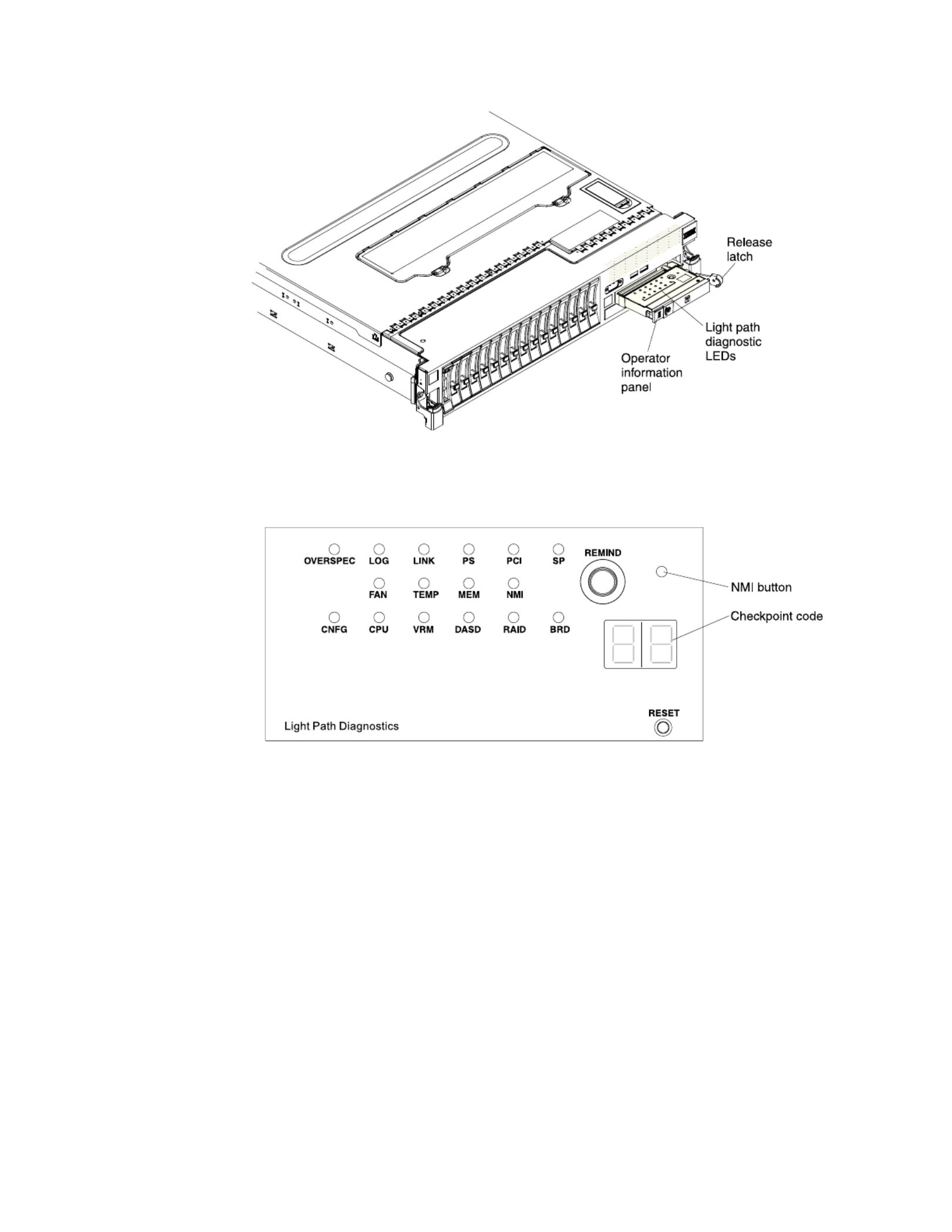
The following illustration shows the LEDs and controls on the light path
diagnostics panel.
v Remind button: This button places the system-error LED on the front panel into
Remind mode. In Remind mode, the system-error LED flashes once every 2
seconds until the problem is corrected, the server is restarted, or a new problem
occurs.
By placing the system-error LED indicator in Remind mode, you acknowledge
that you are aware of the last failure but will not take immediate action to
correct the problem.
v NMI button: Press this button to force a nonmaskable interrupt to the
microprocessor. You might have to use a pen or the end of a straightened paper
clip to press the button. You can also use it to force a blue screen memory
dump. Use this button only when you are directed to do so by the IBM service
support.
v Checkpoint code display: This display provides a checkpoint code that indicates
the point at which the system stopped during the boot block and POST. A
checkpoint code is either a byte or a word value that is produced by UEFI. The
display does not provide error codes or suggest components to be replaced.
v Reset button: Press this button to reset the server and run the power-on self-test
(POST). You might have to use a pen or the end of a straightened paper clip to
press the button. The Reset button is in the lower-right corner of the light path
diagnostics panel.
20 System x3690 X5 Types 7147, 7148, 7149, and 7192: Installation and User's Guide

For additional information about the LEDs on the light path diagnostics panel, see
the Problem Determination and Service Guide.
Rear view
The following illustrations show the connectors and LEDs on the rear of the server.
PCI
slot 1
PCI
slot 2
PCI
slot 3
PCI
slot 4
PCI
slot 5
Power
supply 3
Power
connectors
System
management
Ethernet
connector
Video Serial
connector
USBs
3 - 4
USBs
5 - 6
Ethernet 1 Ethernet 2
Power
supply 1
Power
supply 2
Power
supply 4
QPI
port 1
QPI
port 2
AC LED
(green)
DC LED
(green)
Power-supply
error LED
(amber)
Power-on LED (green)
Locator LED (blue)
System error LED (amber)
Ethernet
activity LED
Ethernet
link LED
QPI link LEDs
v QPI ports: Insert either a QPI cable or a filler panel in each of these connectors.
v PCI riser slot 1: Insert the PCI riser card with two slots or the PCI riser cards
with one slot into this slot. Standard models of the server come with two PCI
Express riser assemblies. See “Installing an adapter” on page 70 for the
supported adapters for these riser-cards.
v PCI riser slot 2: Insert the PCI riser card with three slots into this slot. Standard
models of the server come with two PCI Express riser assemblies. See “Installing
an adapter” on page 70 for information about adapters that this riser card
support.
v Power connector: Connect the power cord to this connector.
v AC power LED: Each hot-swap power supply has an ac power LED and a dc
power LED. When the ac power LED is lit, it indicates that sufficient power is
Chapter 1. The System x3690 X5 Types 7147, 7148, 7149, and 7192 server 21

v Ethernet activity LEDs: When these LEDs are lit, they indicate that the server is
transmitting to or receiving signals from the Ethernet LAN that is connected to
the Ethernet port.
v Ethernet link LEDs: When these LEDs are lit, they indicate that there is an
active link connection on the 10BASE-T, 100BASE-TX, or 1000BASE-TX interface
for the Ethernet port.
v Ethernet connectors: Use either of these connectors to connect the server to a
network. When you use the Ethernet 1 connector, the network can be shared
with the IMM through a single network cable.
Server power features
When the server is connected to an ac power source but is not turned on, the
operating system does not run, and all core logic except for the service processor
(the Integrated Management Module) is shut down; however, the server can
respond to requests to the service processor, such as a remote request to turn on
the server. The power-on LED flashes to indicate that the server is connected to ac
power but is not turned on.
Turning on the server
Approximately 5 seconds after the server is connected to ac power, one or more
fans might start running to provide cooling while the server is connected to power
and the power-on button LED will blink quickly. Approximately 1 to 3 minutes
after the server is connected to ac power, the power-control button becomes active
(the power-on LED will blink slowly), and one or more fans might start running to
provide cooling while the server is connected to power. You can turn on the server
by pressing the power-control button.
The server can also be turned on in any of the following ways:
v If a power failure occurs while the server is turned on, the server will restart
automatically when power is restored.
v If your operating system supports the Wake on LAN feature, the Wake on LAN
feature can turn on the server.
Note: When 4 GB or more of memory (physical or logical) is installed, some
memory is reserved for various system resources and is unavailable to the
operating system. The amount of memory that is reserved for system resources
depends on the operating system, the configuration of the server, and the
configured PCI options.
Chapter 1. The System x3690 X5 Types 7147, 7148, 7149, and 7192 server 23
Turning off the server
When you turn off the server and leave it connected to ac power, the server can
respond to requests to the service processor, such as a remote request to turn on
the server. While the server remains connected to ac power, one or more fans
might continue to run. To remove all power from the server, you must disconnect
it from the power source.
Some operating systems require an orderly shutdown before you turn off the
server. See your operating-system documentation for information about shutting
down the operating system.
Statement 5
CAUTION:
The power control button on the device and the power switch on the power
supply do not turn off the electrical current supplied to the device. The device
also might have more than one power cord. To remove all electrical current from
the device, ensure that all power cords are disconnected from the power source.
1
2
The server can be turned off in any of the following ways:
vYou can turn off the server from the operating system, if your operating system
supports this feature. After an orderly shutdown of the operating system, the
server will turn off automatically.
vYou can press the power-control button to start an orderly shutdown of the
operating system and turn off the server, if your operating system supports this
feature.
vIf the operating system stops functioning, you can press and hold the
power-control button for more than 4 seconds to turn off the server.
vThe server can be turned off by Wake on LAN feature with the following
limitation:
Note: When you install any PCI adapter, the power cords must be disconnected
from the power source before you remove the PCI Express riser-card assembly.
Otherwise, the active power management event signal will be disabled by the
system-board logic, and the Wake on LAN feature might not work. However,
after the server is powered on locally, the active power management event signal
will be enabled by the system-board logic.
vThe integrated management module (IMM) can turn off the server as an
automatic response to a critical system failure.
24 System x3690 X5 Types 7147, 7148, 7149, and 7192: Installation and User's Guide

IBM MAX5 for System x memory expansion module
If you purchased an optional IBM MAX5 for System x (MAX5) memory expansion
module, it supports up to 32 DDR3 DIMMs, two 675-watt power supplies, and five
40 mm hot-swap speed-controlled fans. It provides added memory and multi-node
scaling support for host servers. The MAX5 expansion module is based on eX5, the
next generation of Enterprise X-Architecture. The MAX5 expansion module is
designed for performance, expandability, and scalability; the fans and power
supplies use hot-swap technology for easy replacement without requiring that
expansion module be turned off.
Note:
1. Before you attach a MAX5 to the server and try to use it, you must update the
server firmware with the latest level of firmware or code. If you attach and try
to use the MAX5 without updating the server firmware, you might get
unexpected system behavior or the server might not power on. For special
instructions to follow before you attach the MAX5 to the server, go to
http://www.ibm.com/support/entry/portal/docdisplay?lndocid=MIGR-
5085756.
2. When you add an optional MAX5 to your server configuration and you plan to
use the optional USB flash device with VMware ESXi embedded hypervisor
software, see the documentation that comes with the USB flash device and the
operating system installation instructions for installing VMware ESXi (or ESX,
depending on your environment) on your server at the IBM website at
http://www.ibm.com/supportportal/. The documentation provides additional
installation and configuration information that you need to follow before you
use the MAX5.
If you are adding an optional MAX5 , see the rack instructions that comes with the
cable option kit.
The following illustration shows the MAX5 memory expansion module. The
illustrations in this document might differ slightly from your hardware.
See http://www.ibm.com/systems/info/x86servers/serverproven/compat/us/ for
a list of supported optional devices for the MAX5 memory expansion module.
For information about the terms of the warranty for the MAX5 expansion module,
see the documentation that comes with the expansion module.
Chapter 1. The System x3690 X5 Types 7147, 7148, 7149, and 7192 server 25

Table 2. MAX5 expansion module features and operating specifications (continued)
Acoustical noise emissions: For
maximum system configurations (32
DIMMs installed)
v Sound power (idling): 6.2 bels
v Sound power (operating): 6.2 bels
v Sound pressure (idling): 48 dBA
v Sound pressure (operating): 48
dBA
Size:
v Height: 4.4 cm (1.73 in.)
v Depth: 72.4 cm (28.5 in.)
v Width: 48.3 cm (19.0 in.)
v Weight: approximately 12.8 kg
(28.2 lb) for a standard unit; when
fully configured, 15.4 kg (33.9 lb)
Environment:
v Air temperature:
– Enclosure on: 10° to 35°C (50° to
95°F); altitude: 0 to 914.4 m
(3000 ft). Decreased system
temperature by 0.75° for every
1000 ft. increase in altitude.
– Enclosure off: 5° to 45°C (41° to
113`°F)
– Shipment: -40°C to +60°C (-40°F
to 140°F
v Humidity:
– Enclosure on: 20% to 80%;
maximum dew point: 21°C
(70°F)
– Enclosure off: 8% to 80%;
maximum dew point: 27°C
(80°F)
– Shipment: 5% to 100%
v Particulate contamination:
Attention: Airborne particulates
and reactive gases acting alone or
in combination with other
environmental factors such as
humidity or temperature might
pose a risk to the server. For
information about the limits for
particulates and gases, see
“Particulate contamination” on
page 155.
Heat output
Approximate heat:
v Minimum configuration: 314 Btu
per hour (92 watts)
v Maximum configuration 2048 Btu
per hour (600 watts)
Electrical input:
v Sine-wave input (50 - 60 Hz)
required
v Input voltage low range:
– Minimum: 90 V ac
– Maximum: 136 V ac
v Input voltage high range:
– Minimum: 198 V ac
– Maximum: 264 V ac
v Approximate input
kilovolt-amperes (kVA):
– Minimum: 0.1 kVA
– Maximum: 0.6 kVA
Note:
1. Power consumption and heat
output vary depending on the
number and type of optional
features that are installed and the
power-management optional
features that are in use.
2. These levels were measured in
controlled acoustical
environments according to the
procedures specified by the
American National Standards
Institute (ANSI) S12.10 and ISO
7779 and are reported in
accordance with ISO 9296. Actual
sound-pressure levels in a given
location might exceed the average
stated values because of room
reflections and other nearby noise
sources. The declared
sound-power levels indicate an
upper limit, below which a large
number of computers will
operate.
Chapter 1. The System x3690 X5 Types 7147, 7148, 7149, and 7192 server 27

What the MAX5 offers
The IBM MAX5 for System x (MAX5) memory expansion module provides several
features for easy operation, including the following features:
v Customer replaceable units (CRUs)
The major CRUs in the MAX5 expansion module are memory modules, fans,
and power supplies. See “MAX5 components” on page 117 for the supported
MAX5 components.
v Light path diagnostics LEDs
The MAX5 expansion module has light path LEDs (front and rear) to indicate
hardware, scaling, and power problems.
v Redundant cooling and power capabilities
The MAX5 expansion module supports a maximum of two 675-watt hot-swap
power supplies and five single-motor hot-swap fans, which provides
redundancy and hot-swap capability. The redundant cooling by the fans enables
continued operation if one fan fails. The MAX5 comes with one 675-watt
hot-swap power supply and five fans. If a problem occurs with one of the power
supplies, the other power supply can meet the power requirements.
v Large memory capacity
The memory bus supports up to 512 GB of memory. The memory controller
supports error correcting code (ECC) for up to 32 industry-standard 1066 MHz
PC3-10600R-999 or 1333 MHz PC3-8500, DDR3 (third-generation
double-data-rate), registered, synchronous dynamic random access memory
(SDRAM) dual inline memory modules (DIMMs).
MAX5 reliability, availability, and serviceability features
Three of the most important features in product design are reliability, availability,
and serviceability (RAS). These factors help to ensure that the integrity of the data
processed in your MAX5 memory expansion module is preserved, that the
expansion module is available when you want to use it, and should a failure occur,
you can easily diagnose and repair the failure with minimal inconvenience.
The following is an abbreviated list of the RAS features that the expansion module
supports:
v 1-year parts and 1-year labor limited warranty or it assumes the warranty of the
x3690 server when attached, whichever is longer.
v Chipkill memory protection
v Hot-swap and redundant cooling with fan-speed-sensing capability (front
serviceability)
v Hot-swap and redundant power supplies (rear serviceability)
v Information LED panel
v In-rack serviceability
v Memory redundant bit steering (RBS) and error correcting code (ECC)
v Memory mirroring support (mirrored DIMMs are mutually exclusive of each
other)
v QuickPath Interconnect (QPI) fail down
v Rear serviceability power supplies
28 System x3690 X5 Types 7147, 7148, 7149, and 7192: Installation and User's Guide

MAX5 indicators, LEDs, and power
This section describes the indicators and light-emitting diodes (LEDs) on the front
and rear of the IBM MAX5 for System x (MAX5) memory expansion module.
Front view
The following illustration shows the indicators on the front of the MAX5 expansion
module. All of the LEDs are controlled by the host server integrated management
module (IMM).
Note: The MAX5 memory expansion module does not have a power-on. The
MAX5 and all other functions are controlled by the host server to which it is
connected.
Power-on
LED
Locator
button/LED
Power supply
error LED
Memory
LEDerror
Link
LED
error
Fan
LED
error
System board
LEDerror
Configuration
LEDerror
v Information panel: This panel contains the indicators for the MAX5 expansion
module.
– When this green LED is lit, it indicates that the MAX5 isPower-on LED:
powered on.
– Use this blue LED to locate the MAX5 expansion module. TheLocate LED:
locate LED also has a button that you can press to light up other servers or
other MAX5 expansion modules to which the MAX5 expansion module is
connected.
– When this amber LED is lit, it indicates aPower supply fault (error) LED:
faulty hot-swap power-supply.
– When this amber LED is lit, it indicates a DIMMMemory error LED:
problem.
– When this amber LED is lit, indicates that a QPI link fault orLink error LED:
a EXA link fault has occurred. The port LED for the link that has been
disconnected will not be lit on the rear of the MAX5. EXA link LEDs are on
the rear of the MAX5 expansion module, and the QPI link LEDs are on the
server to which the MAX5 is connected.
– When this amber LED is lit, it indicates a fan error.Fan error LED:
– When this amber LED is lit, it indicates a MAX5System board error LED:
system-board tray error.
– When this amber LED is lit, it indicates aConfiguration error LED:
configuration error. The memory LED might be lit to indicate a memory
configuration error.
Chapter 1. The System x3690 X5 Types 7147, 7148, 7149, and 7192 server 29

Turning the MAX5 on and off
Because the MAX5 expansion module is controlled by the server, turning on the
MAX5 refers to connecting the MAX5 power cord to the power source and
pressing the power-control button on the host server that is connected to the
MAX5 expansion module and is configured to identify the expansion module.
Normally, the operating system on the server starts, and the server issues a
power-on request to the MAX5. The IBM MAX5 for System x (MAX5) memory
expansion module is turned off only if the connected server issues a power-off
request and you disconnect the MAX5 power cord from the power source. You
cannot turn off the MAX5 expansion module manually.
Statement 5
CAUTION:
The power control button on the device and the power switch on the power
supply do not turn off the electrical current supplied to the device. The device
also might have more than one power cord. To remove all electrical current from
the device, ensure that all power cords are disconnected from the power source.
1
2
You can disconnect the MAX5 expansion module power cords from the power
source to shut off all power immediately without damaging the MAX5, but it
might cause an unrecoverable error and loss of data on the connected server.
Chapter 1. The System x3690 X5 Types 7147, 7148, 7149, and 7192 server 31

32 System x3690 X5 Types 7147, 7148, 7149, and 7192: Installation and User's Guide

Installing hardware devices in the server
This following sections provide detailed instructions for installing optional
hardware devices in the server.
Instructions for IBM Business Partners
In addition to the instructions in this chapter for installing optional hardware
devices, updating firmware and device drivers, and completing the installation,
IBM Business Partners must also complete the following steps:
1. Before you configure a server for a customer, complete the Solution Assurance
checklist at http://w3.ibm.com/support/assure/assur30i.nsf/webindex/
sa294/.
2. After you have confirmed that the server starts correctly and recognizes the
newly installed devices and that no error LEDs are lit, run the Dynamic System
Analysis (DSA) stress test. For information about using DSA, see the Problem
Determination and Service Guide.
3. Shut down and restart the server multiple times to ensure that the server is
correctly configured and functions correctly with the newly installed devices.
4. Save the DSA log as a file and send it to IBM.
5. To ship the server, repackage it in the original undamaged packing material
and observe IBM procedures for shipping.
Support information for IBM Business Partners is available at http://
www.ibm.com/partnerworld/pwhome.nsf/weblook/index_us.html.
Server components
The following illustration shows the major components in the server. The
illustrations in this document might differ slightly from your hardware.
34 System x3690 X5 Types 7147, 7148, 7149, and 7192: Installation and User's Guide

system support hot-swap capability, you can remove or install the component
while the server is running. (Orange can also indicate touch points on hot-swap
components.) See the instructions for removing or installing a specific hot-swap
component for any additional procedures that you might have to perform before
you remove or install the component.
System-board internal connectors
The following illustration shows the internal connectors on the system board.
36 System x3690 X5 Types 7147, 7148, 7149, and 7192: Installation and User's Guide

System-board external connectors
The following illustration shows the external input/output connectors on the
system board.
Chapter 2. Installing optional devices 37
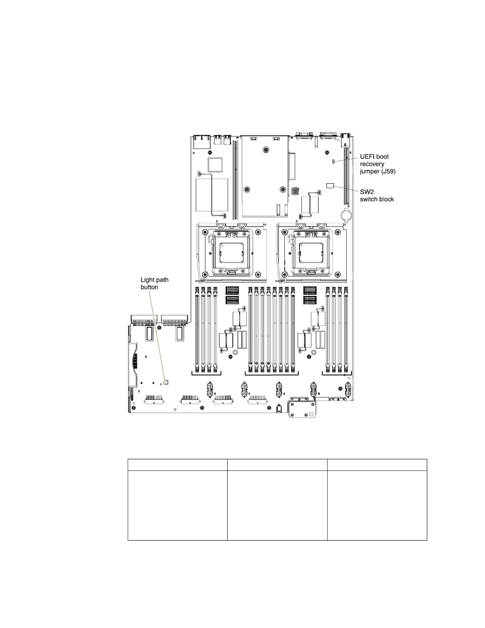
System-board switches and jumpers
The following illustration shows the location and description of the switches and
jumpers.
Note: If there is a clear protective sticker on the top of the switch block, you must
remove and discard it to access the switch.
The following table describes the jumper on the system board.
Table 3. System board jumper
Jumper number Jumper name Jumper setting
J59 UEFI boot recovery jumper v Pins 1 and 2: Normal
(default) Loads the
primary server firmware
ROM page.
v Pins 2 and 3: Loads the
secondary (backup) server
firmware ROM page.
38 System x3690 X5 Types 7147, 7148, 7149, and 7192: Installation and User's Guide
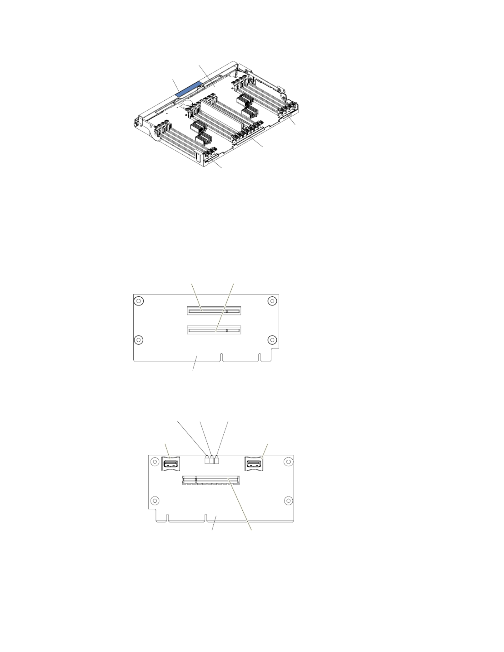
Tray handle
Memory tray
DIMM
17-20
LEDs
DIMM
21-28
LEDs
DIMM
29-32
LEDs
PCI riser card with three slots
The following illustrations show the connectors and LEDs on the optional
three-slot PCI riser card:
Side 1:
PCI riser card
Slot 3, PCI Express
Gen2 , low profilex8
Slot 4, PCI Express
Gen2 , low profilex8 (x4)
Side 2:
USB connector
USB embedded
hypervisor flash
device connector
PCI slot 3
error LEDs
Slot 5, PCI Express
Gen2 , low profilex8
PCI riser card
PCI slot 4
error LEDs
PCI slot 5
error LEDs
42 System x3690 X5 Types 7147, 7148, 7149, and 7192: Installation and User's Guide
Specyfikacje produktu
| Marka: | Lenovo |
| Kategoria: | serwer |
| Model: | System x3690 X5 |
Potrzebujesz pomocy?
Jeśli potrzebujesz pomocy z Lenovo System x3690 X5, zadaj pytanie poniżej, a inni użytkownicy Ci odpowiedzą
Instrukcje serwer Lenovo

16 Września 2024
4 Września 2024
2 Września 2024
28 Sierpnia 2024
28 Sierpnia 2024
28 Sierpnia 2024
28 Sierpnia 2024
28 Sierpnia 2024
28 Sierpnia 2024
28 Sierpnia 2024
Instrukcje serwer
- serwer Sony
- serwer Supermicro
- serwer Gigabyte
- serwer Acer
- serwer Technics
- serwer Hikvision
- serwer Fujitsu
- serwer Conceptronic
- serwer StarTech.com
- serwer Asus
- serwer Medion
- serwer TRENDnet
- serwer MSI
- serwer Toshiba
- serwer D-Link
- serwer ATen
- serwer APC
- serwer HP
- serwer Tripp Lite
- serwer Cisco
- serwer Moxa
- serwer Synology
- serwer Lindy
- serwer ZyXEL
- serwer Dell
- serwer Linksys
- serwer Digitus
- serwer Vimar
- serwer Netgear
- serwer Black Box
- serwer ELAC
- serwer Intellinet
- serwer HGST
- serwer Revox
- serwer Naim
- serwer SEH
- serwer Planet
- serwer NEC
- serwer LevelOne
- serwer Digi
- serwer Axis
- serwer Asrock
- serwer Abus
- serwer Rocstor
- serwer Western Digital
- serwer Smart-AVI
- serwer Promise Technology
- serwer QNAP
- serwer Chenbro Micom
- serwer Allnet
- serwer Veritas
- serwer IStarUSA
- serwer Silverstone
- serwer Ernitec
- serwer AVerMedia
- serwer Atlona
- serwer Gefen
- serwer Hanwha
- serwer Quantum
- serwer Blackmagic Design
- serwer Kathrein
- serwer Eaton
- serwer Monacor
- serwer Sonnet
- serwer In Win
- serwer Teo
- serwer Megasat
- serwer Areca
- serwer Kramer
- serwer KanexPro
- serwer Raritan
- serwer AMX
- serwer C2G
- serwer Acti
- serwer Sitecom
- serwer Maxdata
- serwer Matrox
- serwer Flir
- serwer Buffalo
- serwer GeoVision
- serwer LaCie
- serwer Valcom
- serwer Asustor
- serwer Intel
- serwer Fantec
- serwer Freecom
- serwer Seagate
- serwer Iomega
- serwer Luxman
- serwer Ibm
- serwer Provision ISR
- serwer TAIDEN
- serwer SIIG
- serwer Advantech
- serwer Extron
- serwer Avocent
- serwer Teradek
- serwer Silex
- serwer Sun
- serwer MvixUSA
- serwer Dual Bay
- serwer Raidsonic
- serwer EMC
- serwer Infortrend
- serwer Opengear
- serwer G-Technology
- serwer EXSYS
- serwer Middle Atlantic
- serwer Mr. Signal
- serwer Atlantis Land
- serwer Lantronix
- serwer NETSCOUT
- serwer Mobotix
- serwer Origin Storage
Najnowsze instrukcje dla serwer

9 Kwietnia 2025
2 Kwietnia 2025

2 Kwietnia 2025
2 Kwietnia 2025
28 Marca 2025
28 Marca 2025
28 Marca 2025

10 Marca 2025
10 Marca 2025
10 Marca 2025