Instrukcja obsługi HP OfficeConnect OC20
Przeczytaj poniżej 📖 instrukcję obsługi w języku polskim dla HP OfficeConnect OC20 (4 stron) w kategorii router. Ta instrukcja była pomocna dla 5 osób i została oceniona przez 2 użytkowników na średnio 4.5 gwiazdek
Strona 1/4
OfficeConnect OC20
Access Point
Installation Guide
Rev 06 | March 2018 1
The OfficeConnect OC20 wireless access points (APs) support
IEEE802.11ac standards for high-performance WLAN, and are
equipped with two radios. Multiple-in, Multiple-output (MIMO)
technology allows these APs to deliver high-performance
802.11n 2.4 GHz and 802.11ac 5 GHz functionality, while also
supporting 802.11a/b/g wireless services.
The OC20 access points provide the following capabilities:
Wireless transceiver
IEEE 802.11a/b/g/n/ac operation as a wireless access point
or air monitor
Compatibility with IEEE 802.3af PoE
Centralized management configuration and upgrade
Integrated Bluetooth Low Energy (BLE) Radio
Package Contents
OC20 access point
Ceiling Rail Adapter (spare: AP-220-MNT-C1)
AP-220-MNT-W1W
Quick Start Guide
!
This device must be professionally installed and serviced
by a trained ACMP or similar HPE-certified technician.
HPE access points are classified as radio transmission
devices, and are subject to government regulations of the
host country. The network administrator(s) is/are
responsible for ensuring that configuration and operation
of this equipment is in compliance with their country’s
regulations. For complete list of approved channels in
your country, refer to the refer to the ArubaOS
Downloadable Regulatory Table Release Notes at http://
h20565.www2.hpe.com/hpsc/doc/public/
display?docId=a00026718en_us.
Inform your supplier if there are any incorrect, missing, or
damaged parts. If possible, retain the carton, including
the original packing materials. Use these materials to
repack and return the unit to the supplier if needed.
Software
OC20 Hardware Overview
Figure 1 Front
LEDs
The OC20 access points have two LEDs that indicate the system
and radio status of the device. These two LEDs can be
configured into three separate modes:
Normal mode (by default): See Table 1
Both LEDs off
Blink mode: Both LEDs blink green (synchronized)
!
Access points are radio transmission devices and are
subject to governmental regulation. Network
administrators responsible for the configuration and
operation of access points must comply with local
broadcast regulations. Specifically, access points must
use channel assignments appropriate to the location in
which the access point will be used.
Table 1 OC20 LEDs Status in Normal Mode
LED Color/State Meaning
System
Status
(Left)
Off Device powered off
Green-
Blinking
Device booting, not ready for use
Green- Solid Device ready for use, no restrictions
Green-
Flashing
Device ready for use, uplink negotiated in
sub optimal speed (<1Gbps)
Red- Solid System error condition
Radio
Status
(Right)
Off Device powered off, or both radios
disabled
Green- Solid Both radios enabled in access mode
Green-
Blinking
One radio enabled in access mode
Amber- Solid Both radios enabled in monitor mode
Amber-
Blinking
One radio enabled in monitor mode
Alternating Green: one radio in access mode
Amber: one radio in monitor mode
System Status
Radio Status

2OfficeConnect OC20 Access Point | Installation Guide
Figure 2 Back Panel
Console Port
The serial console port is located at the back of the OC20 and is
a 4-pin connector covered by a dust cover. An optional serial
adapter cable (AP-CBL-SER) is sold separately to connect the
AP to a serial terminal or a laptop for direct local management.
Ethernet Port
The OC20 access points are equipped with one 10/100/
1000Base-T (RJ-45) auto-sensing, MDI/MDX Ethernet port
(ENET0) for wired network connectivity. This port supports IEEE
802.3af Power over Ethernet (PoE), as a standard defined
Powered Device (PD) from a Power Sourcing Equipment (PSE)
such as a PoE midspan injector or network infrastructure that
supports PoE.
Kensington Lock Slot
The OC20 access points are equipped with a Kensington lock
slot for additional security.
Reset Button
To reset a OC20 access point to factory default settings:
1. Press and hold down the reset button using a small, narrow
object such as a paper clip while the OC20 access point is
not powered on (either via DC power or PoE.)
2. Connect the power supply (DC or PoE) to the OC20 access
point while the reset button is being held down.
3. Release the reset button on the OC20 access point after 15
seconds.
DC Power Socket
If PoE is not available, an optional AP-AC-12V30B power
adapter kit (sold separately) can be used to power the OC20
access points.
Additionally, a locally-sourced AC-to-DC adapter (or any DC
source) can be used to power this device, as long as it complies
with all applicable local regulatory requirements and the DC
interface meets the following specifications:
12 Vdc (+/- 5%) and at least 12W
Center-positive 2.1/5.5 mm circular plug, 9.5 mm length
Before You Begin
Pre-Installation Checklist
Before installing your OC20 access points, ensure that you have
the following:
Cat5E or better UTP cable of required length
One of the following power sources:
IEEE 802.3af-compliant Power over Ethernet (PoE)
source.
HPE Aruba AP-AC-12V30B power adapter kit (sold
separately)
Identifying Specific Installation Locations
You can mount the OC20 access point on the ceiling or a wall.
Use your RF plan or wireless deployment modeling tools to
determine the proper installation location(s). Each location
should be as close as possible to the center of the intended
coverage area and should be free from obstructions or obvious
sources of interference. These RF absorbers/reflectors/
interference sources will impact RF propagation and should
have been accounted for during the planning phase and
adjusted for in your RF plan.
Identifying Known RF Absorbers, Reflectors
and Interference Sources
Identifying known RF absorbers, reflectors, and interference
sources while in the field during the installation phase is critical.
Make sure that these sources are taken into consideration when
you attach an access point to its fixed location. Examples of
sources that degrade RF performance include:
Cement and brick
Objects that contain water
Metal
Microwave ovens
Wireless phones and headsets
CONSOLE
ENET
12V 1A
350mA57V
Console Port
Ethernet Port DC Power Socket
Reset Button
Kensington
Lock Slot
!
FCC Statement: Improper termination of access points
installed in the United States configured to non-US model
controllers will be in violation of the FCC grant of
equipment authorization. Any such willful or intentional
violation may result in a requirement by the FCC for
immediate termination of operation and may be subject to
forfeiture (47 CFR 1.80).
!
EU Statement:
Lower power radio LAN product operating in 2.4 GHz and
5 GHz bands.
Produit radio basse puissance pour réseau local opérant
sur les fréquences 2,4 GHz et 5 GHz.
Niedrigenergie-Funk-LAN-Produkt, das im 2,4-GHz- und
im 5-GHz-Band arbeitet.
Apparati Radio LAN a bassa Potenza, operanti a 2.4 GHz
e 5 GHz.

3OfficeConnect OC20 Access Point | Installation Guide
Installing the Access Point
The OC20 access point ships with a ceiling rail adapter and an
AP-220-MNT-W1W mount bracket. Additional ceiling or wall
mount kits are sold separately as accessories.
Using the Ceiling Rail Adapter
The included ceiling rail adapter can be used to attach the OC20
access point to a 9/16” or 15/16” ceiling rail.
1. Pull the necessary cables through a prepared hole in the
ceiling tile near where the access point will be placed.
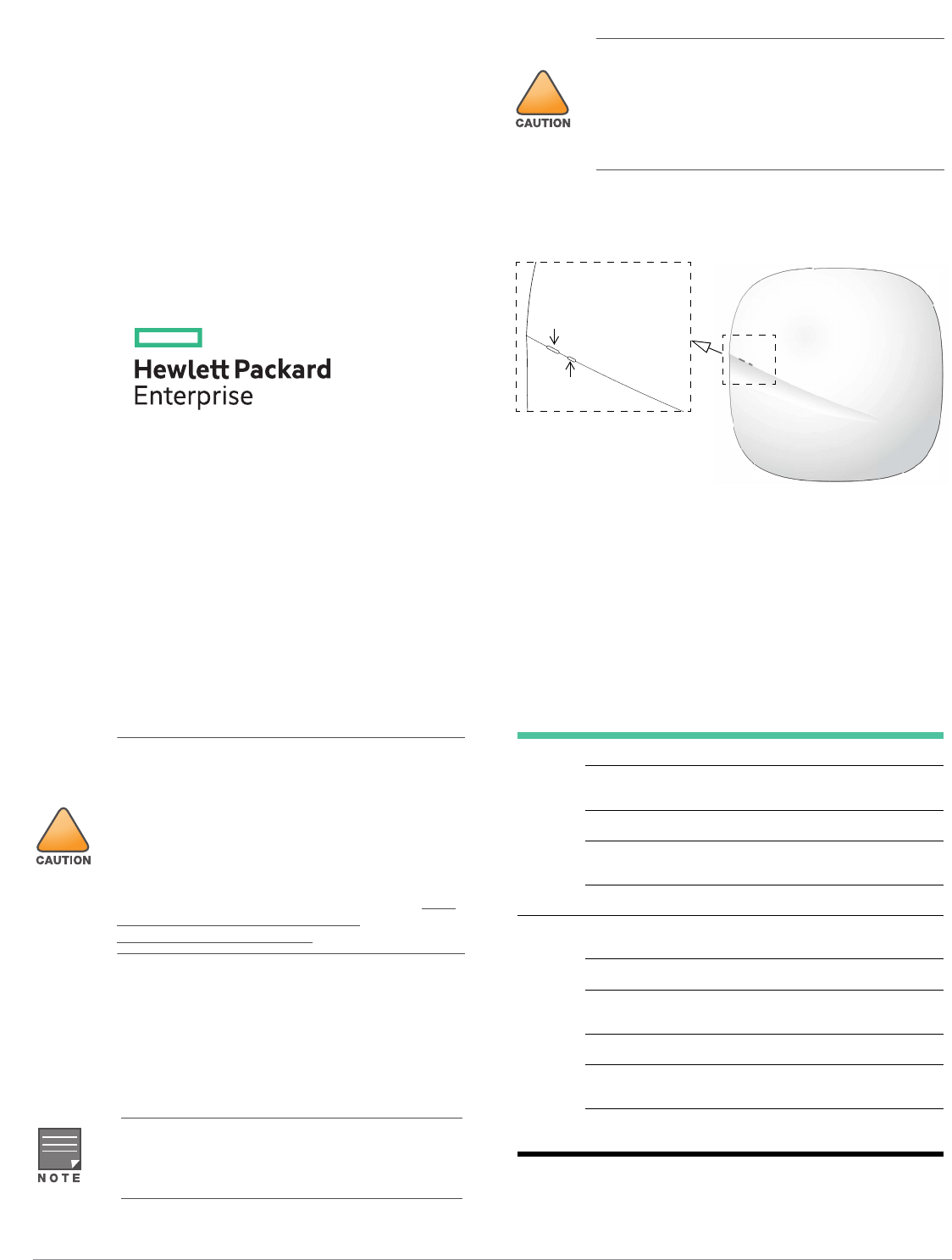
2. Place the adapter against the back of the access point with
the adapter at an angle of approximately 30 degrees to the
tabs (see Figure 3).
3. Twist the adapter clockwise until it snaps into place in the
tabs (see Figure 3).
Figure 3 Attaching the Ceiling Rail Adapter to the AP
4. Hold the access point next to the ceiling tile rail with the
mounting slots at approximately a 30-degree angle to the
ceiling tile rail (see Figure 4 and Figure 5). Make sure that
any cable slack is above the ceiling tile.
5. Pushing toward the ceiling tile, rotate the access point
clockwise until the device clicks into place on the ceiling tile
rail.
Figure 4 Mounting the Access Point to a 15/16” ceiling rail
Figure 5 Mounting the Access Point to a 9/16” ceiling rail
Using the AP-220-MNT-W1W Bracket
The included AP-220-MNT-W1W bracket can be used to mount
the OC20 access point to a wall.
1. Begin by attaching the bracket to the wall as shown in Figure
6 or Figure 7.
a. Install any necessary wall anchors. Wall anchors are not
included in the package.
b. Align the screw holes in the bracket with the previously
installed anchors or demarcated screw points.
c. Insert the screws to secure the bracket. Screws are not
included in the package.
Figure 6 Attaching the Bracket to a Wall
Figure 7 Attaching the Bracket to a Wall (Alternate)
2. Attach the AP to the secured bracket as shown in Figure 8.
a. Align the AP with the bracket, placing the AP so that its
mounting tabs are at an angle of approximately 30
degrees to the bracket.
3. Pushing toward the wall, rotate the AP clockwise until it
clicks into place (see Figure 8).
Service to all Hewlett Packard Enterprise access points
should be performed by an AMCP certified technician or
similar.
!
The installer is responsible for securing the access point onto
the ceiling tile rail in accordance with the steps below. Failure
to properly install this product may result in physical injury
and/or damage to property.
AP-130_003
AP-130_006
Specyfikacje produktu
| Marka: | HP |
| Kategoria: | router |
| Model: | OfficeConnect OC20 |
Potrzebujesz pomocy?
Jeśli potrzebujesz pomocy z HP OfficeConnect OC20, zadaj pytanie poniżej, a inni użytkownicy Ci odpowiedzą
Instrukcje router HP

5 Lipca 2024
4 Lipca 2024
4 Lipca 2024
4 Lipca 2024
4 Lipca 2024
3 Lipca 2024
28 Czerwca 2024
28 Czerwca 2024
28 Czerwca 2024
28 Czerwca 2024
Instrukcje router
- router Samsung
- router Tenda
- router AEG
- router Motorola
- router Xiaomi
- router Huawei
- router TCL
- router TP-Link
- router Milwaukee
- router Gigabyte
- router Acer
- router Bosch
- router Hikvision
- router Roland
- router Nokia
- router Toolcraft
- router Festool
- router EZVIZ
- router Conceptronic
- router StarTech.com
- router Asus
- router Medion
- router Black & Decker
- router TRENDnet
- router MSI
- router D-Link
- router ATen
- router Siemens
- router Thrustmaster
- router DeWalt
- router Einhell
- router Alcatel
- router Sigma
- router Teltonika
- router Silverline
- router Manhattan
- router Strong
- router Makita
- router Mikrotik
- router Cisco
- router Moxa
- router Synology
- router Gembird
- router ZTE
- router Lindy
- router Zebra
- router ZyXEL
- router Trust
- router LogiLink
- router Dell
- router IFM
- router Linksys
- router Google
- router Digitus
- router Vimar
- router Dahua Technology
- router Schneider
- router Kyocera
- router Sabrent
- router AVMATRIX
- router Renkforce
- router Netgear
- router Thomson
- router AVM
- router BT
- router Totolink
- router Black Box
- router Güde
- router Apple
- router Lancom
- router Zoom
- router Iogear
- router Intellinet
- router Devolo
- router Vtech
- router Mercusys
- router I-TEC
- router Draytek
- router Edimax
- router Razer
- router AirLive
- router EnGenius
- router Planet
- router NEC
- router Blustream
- router LevelOne
- router Digi
- router Milesight
- router Rocstor
- router Hama
- router Ubiquiti Networks
- router Western Digital
- router ModeCom
- router Smart-AVI
- router Barco
- router Sagemcom
- router Juniper
- router Cudy
- router QNAP
- router Arris
- router Netis
- router Anker
- router Allnet
- router Marshall Electronics
- router Hitachi
- router M-life
- router AJA
- router Media-Tech
- router BenQ
- router Atlona
- router FSR
- router Gefen
- router Vivanco
- router Topcom
- router PowerPlus
- router HiKOKI
- router Blackmagic Design
- router Kathrein
- router JUNG
- router Foscam
- router Alfa
- router Porter-Cable
- router Metabo
- router Starlink
- router Keewifi
- router Digital Forecast
- router Keenetic
- router SPL
- router Cotech
- router Skil
- router Alfatron
- router Digitalinx
- router Clas Ohlson
- router KPN
- router Belkin
- router Kramer
- router KanexPro
- router Kopul
- router BZBGear
- router RGBlink
- router Key Digital
- router UPC
- router Lumantek
- router Allied Telesis
- router Actiontec
- router Proximus
- router Eminent
- router Sitecom
- router Sagem
- router Nilox
- router Sonos
- router Patton
- router Techly
- router Envivo
- router Buffalo
- router Nest
- router Vodafone
- router ICIDU
- router Milan
- router Konig
- router AT&T
- router Sweex
- router Aruba
- router Phicomm
- router Kasda
- router Technicolor
- router Verizon
- router Billion
- router T-Mobile
- router RAVPower
- router Hawking Technologies
- router Nexxt
- router WyreStorm
- router Beafon
- router Kraun
- router LTS
- router Zolid
- router Telstra
- router Holzmann
- router SIIG
- router Eero
- router Advantech
- router Mercku
- router Hercules
- router Xantech
- router Intelix
- router MuxLab
- router Pentagram
- router Ocean Matrix
- router Comprehensive
- router Arcadyan
- router Digiconnect
- router Ubee
- router SMC
- router Tele 2
- router Kogan
- router Peak
- router CradlePoint
- router Davolink
- router Sixnet
- router AVPro Edge
- router Evolution
- router 7inova
- router Predator
- router A-NeuVideo
- router United Telecom
- router F-Secure
- router Rosewill
- router Digicom
- router On Networks
- router Wisetiger
- router Leoxsys
- router Readynet
- router OneAccess
- router Accelerated
- router Nexaira
- router Hamlet
- router Approx
- router T-com
- router Amped Wireless
- router Cambium Networks
- router 3Com
- router Avenview
- router Ruckus Wireless
- router Dovado
- router Mach Power
- router EXSYS
- router NetComm
- router Comtrend
- router Premiertek
- router Bea-fon
- router GL.iNet
- router Shinybow
- router Edgewater
- router Atlantis Land
- router Lantronix
- router PulseAudio
- router Luxul
- router DVDO
- router StarIink
- router Silentwind
- router Keezel
- router VigilLink
Najnowsze instrukcje dla router

9 Kwietnia 2025
9 Kwietnia 2025

8 Kwietnia 2025

3 Kwietnia 2025

2 Kwietnia 2025
1 Kwietnia 2025
30 Marca 2025
30 Marca 2025
30 Marca 2025
30 Marca 2025