Instrukcja obsługi Dell PowerEdge C6320
Przeczytaj poniżej 📖 instrukcję obsługi w języku polskim dla Dell PowerEdge C6320 (87 stron) w kategorii serwer. Ta instrukcja była pomocna dla 12 osób i została oceniona przez 2 użytkowników na średnio 4.5 gwiazdek
Strona 1/87

Dell PowerEdge C6320
O
O
O
OOw
w
w
wwn
n
n
nne
e
e
eer
r
r
rr'
'
'
''s
s
s
ss
M
M
M
MMa
a
a
aan
n
n
nnu
u
u
uua
a
a
aal
l
l
ll
Regulatory Model: B08S
Regulatory Type: B08S003
July 2020
Rev. A05

Notes, cautions, and warnings
NOTE: A NOTE indicates important information that helps you make better use of your product.
CAUTION: A CAUTION indicates either potential damage to hardware or loss of data and tells you how to avoid
the problem.
WARNING: A WARNING indicates a potential for property damage, personal injury, or death.
© 2017 - 2018 Dell Inc. or its subsidiaries. All rights reserved. Dell, EMC, and other trademarks are trademarks of Dell Inc. or its subsidiaries.
Other trademarks may be trademarks of their respective owners.

Chapter 1: Dell PowerEdge C6320 product overview......................................................................8
Supported configurations for PowerEdge C6320 system.........................................................................................8
Accessing system features during startup.................................................................................................................... 9
Front panel features and indicators...............................................................................................................................10
Hard drive indicator patterns........................................................................................................................................... 11
Back panel features and indicators................................................................................................................................13
LAN indicator codes.......................................................................................................................................................... 14
Power and system board indicator codes....................................................................................................................15
Power Supply Unit indicator codes................................................................................................................................16
1400 W AC or HVDC Power supply units............................................................................................................... 16
1600 W AC or HVDC Power supply unit................................................................................................................. 17
Baseboard Management Controller (BMC) heart beat LED................................................................................... 18
System configuration limitations by Intel Xeon processor E5-2600 v3 and E5-2600 v4 product family ... 18
Locating your system Service Tag.................................................................................................................................21
Chapter 2: Documentation resources...........................................................................................24
Chapter 3: Technical specifications............................................................................................. 27
Chassis dimensions........................................................................................................................................................... 27
Processor specifications..................................................................................................................................................28
PSU specifications............................................................................................................................................................ 28
System battery specifications ................................................................................................................................ 28
Memory specifications .................................................................................................................................................... 28
Environmental specifications .........................................................................................................................................29
Chapter 4: Initial system setup and configuration........................................................................ 31
Setting up your system.....................................................................................................................................................31
iDRAC configuration.......................................................................................................................................................... 31
Options to set up iDRAC IP address........................................................................................................................31
Options to install the operating system.......................................................................................................................32
Methods to download firmware and drivers......................................................................................................... 32
Chapter 5: Pre-operating system management applications........................................................ 34
Options to manage the pre-operating system applications.................................................................................... 34
System Setup..................................................................................................................................................................... 34
Viewing System Setup............................................................................................................................................... 35
System Setup details..................................................................................................................................................35
System BIOS.................................................................................................................................................................35
iDRAC Settings utility................................................................................................................................................. 58
Device Settings............................................................................................................................................................59
Dell Lifecycle Controller...................................................................................................................................................59
Embedded systems management............................................................................................................................59
Boot Manager.................................................................................................................................................................... 60
Viewing Boot Manager...............................................................................................................................................60
Contents
Contents 3

Boot Manager main menu......................................................................................................................................... 60
PXE boot.............................................................................................................................................................................. 61
Chapter 6: Installing and removing system components.............................................................. 62
Safety instructions............................................................................................................................................................62
Before working inside your system............................................................................................................................... 63
After working inside your system.................................................................................................................................. 63
Recommended tools......................................................................................................................................................... 63
System cover..................................................................................................................................................................... 64
Removing the system cover..................................................................................................................................... 64
Installing the system cover....................................................................................................................................... 65
Inside the system.............................................................................................................................................................. 65
Cooling fans........................................................................................................................................................................66
Removing a cooling fan..............................................................................................................................................66
Installing a cooling fan................................................................................................................................................ 68
Hard drives..........................................................................................................................................................................69
Removing a 3.5-inch hard drive blank....................................................................................................................69
Installing a 3.5-inch hard drive blank...................................................................................................................... 70
Removing a 2.5-inch hard drive blank.................................................................................................................... 70
Installing the 2.5-inch hard drive blank................................................................................................................... 71
Removing a hard drive carrier................................................................................................................................... 71
Installing a hard drive carrier.....................................................................................................................................72
Removing a hard drive from a hard drive carrier................................................................................................. 73
Installing a hard drive into a hard drive carrier..................................................................................................... 74
Installing a 2.5-inch SSD into a 3.5-inch hard drive carrier...............................................................................75
SSD and SSD holder..........................................................................................................................................................77
Removing the SSD and SSD Holder........................................................................................................................77
Installing the SSD and SSD holder...........................................................................................................................79
DC to DC board........................................................................................................................................................... 80
Cable routings for SSD and DC to DC board and LSI 2008...............................................................................81
SATADOM...........................................................................................................................................................................82
Removing the SATADOM.......................................................................................................................................... 82
Installing the SATADOM............................................................................................................................................ 83
Cable routing for SATADOM and LSI 2008.......................................................................................................... 84
Power supply units............................................................................................................................................................84
Removing a power supply unit................................................................................................................................. 84
Installing a power supply unit................................................................................................................................... 85
System board tray.............................................................................................................................................................86
Removing the system board tray ........................................................................................................................... 86
Installing the system board tray ..............................................................................................................................87
System board assembly................................................................................................................................................... 87
Removing a sled ..........................................................................................................................................................87
Installing a sled ............................................................................................................................................................89
Cooling shroud................................................................................................................................................................... 90
Removing the cooling shroud ..................................................................................................................................90
Installing the cooling shroud .....................................................................................................................................91
Heat sinks............................................................................................................................................................................93
Removing the heat sink ............................................................................................................................................ 93
Installing the heat sink .............................................................................................................................................. 94
Processors ......................................................................................................................................................................... 95
4 Contents

Removing a processor ...............................................................................................................................................95
Installing a processor .................................................................................................................................................96
Expansion card assembly and expansion card ...........................................................................................................97
Removing the expansion card.................................................................................................................................. 97
Installing the expansion card.................................................................................................................................... 99
PCI-E slot priority ............................................................................................................................................................ 99
PERC cards....................................................................................................................................................................... 100
Removing the PERC card .......................................................................................................................................100
Installing the PERC card ......................................................................................................................................... 100
Riser card .......................................................................................................................................................................... 101
Optional riser cards.................................................................................................................................................... 101
Removing the riser card............................................................................................................................................101
Installing the riser card............................................................................................................................................. 102
Optional mezzanine cards..............................................................................................................................................103
Removing the optional LSI 2008 SAS mezzanine card.................................................................................... 104
Installing the optional LSI 2008 SAS mezzanine card ..................................................................................... 105
Cable routing for LSI 2008 SAS mezzanine card...............................................................................................105
Removing the 1GbE mezzanine card.....................................................................................................................106
Installing the 1GbE mezzanine card ......................................................................................................................108
Removing the 10GbE mezzanine card .................................................................................................................109
Installing the 10GbE mezzanine card .....................................................................................................................111
Mezzanine card bridge board ........................................................................................................................................111
Removing the mezzanine card bridge board ....................................................................................................... 111
Installing the mezzanine card bridge board..........................................................................................................112
System memory................................................................................................................................................................ 113
Memory slot features ............................................................................................................................................... 113
Supported memory module configuration ........................................................................................................... 113
Removing the memory modules .............................................................................................................................115
Installing the memory modules................................................................................................................................ 116
System battery ................................................................................................................................................................ 118
Replacing the system battery .................................................................................................................................118
System board ................................................................................................................................................................... 119
Removing a system board ....................................................................................................................................... 119
Installing a system board ......................................................................................................................................... 121
Cable routing for onboard SATA cables (1U node) .......................................................................................... 122
Trusted Platform Module...............................................................................................................................................123
Installing the Trusted Platform Module................................................................................................................ 124
Initializing the TPM for BitLocker users............................................................................................................... 124
Initializing the TPM for TXT users......................................................................................................................... 125
Power distribution boards..............................................................................................................................................125
Removing the power distribution board 1............................................................................................................ 125
Removing the power distribution board 2............................................................................................................127
Installing the power distribution board 2..............................................................................................................129
Installing the power distribution board 1.............................................................................................................. 129
Cable routing of the power distribution boards ................................................................................................ 130
Midplanes...........................................................................................................................................................................132
Removing the midplanes.......................................................................................................................................... 132
Installing the midplanes.............................................................................................................................................137
Cable routing–midplane to the hard drive backplane ...................................................................................... 138
Cable routing for middle plane to 2.5-inch hard drive backplane for expander configuration ............... 141
Contents 5

Hard drive backplanes.................................................................................................................................................... 142
Removing the hard drive backplane...................................................................................................................... 144
Installing the hard drive backplane........................................................................................................................ 146
2.5-inch hard drive expander configuration.............................................................................................................. 147
Removing the 2.5-inch hard drive backplane for expander configuration...................................................148
Installing the 2.5-inch hard drive backplane for expander configuration......................................................151
Control panel.....................................................................................................................................................................152
Removing the control panel.................................................................................................................................... 152
Installing the control panel...................................................................................................................................... 155
Sensor board.....................................................................................................................................................................156
Removing the sensor board for 3.5-inch hard drive system...........................................................................156
Installing the sensor board for 3.5-inch hard drive system............................................................................. 157
Cable routing for sensor board and control panel for 3.5-inch hard drive system....................................158
Removing the sensor board for 2.5-inch hard drive system...........................................................................159
Installing the sensor board for 2.5-inch hard drive system.............................................................................160
Cable routing for sensor board and control panel for 2.5-inch hard drive system.....................................161
Chapter 7: Jumpers and connectors .......................................................................................... 162
C6320 system board connectors.................................................................................................................................162
LSI 2008 SAS mezzanine card connectors............................................................................................................... 164
Powerville dual port 1GbE .............................................................................................................................................164
Twinville dual port 10GbE ............................................................................................................................................. 165
Power distribution board 1 connectors ..................................................................................................................... 165
Power distribution board 2 connectors .....................................................................................................................166
Sensor board connectors ............................................................................................................................................. 166
Jumper settings............................................................................................................................................................... 166
Jumper settings on the PowerEdge C6320 system board..............................................................................166
Backplane jumper settings ......................................................................................................................................167
Chapter 8: Troubleshooting your system....................................................................................168
Installation Problems ......................................................................................................................................................168
Minimum configuration to POST ................................................................................................................................ 168
Troubleshooting system startup failure......................................................................................................................169
Troubleshooting external connections....................................................................................................................... 169
Troubleshooting the video subsystem........................................................................................................................169
Troubleshooting a USB device..................................................................................................................................... 169
Troubleshooting a serial input and output device.................................................................................................... 170
Troubleshooting a NIC.....................................................................................................................................................171
Troubleshooting a wet system...................................................................................................................................... 171
Troubleshooting a damaged system............................................................................................................................172
Troubleshooting the system battery........................................................................................................................... 173
Troubleshooting power supply units............................................................................................................................173
Troubleshooting power source problems............................................................................................................. 174
Power supply unit problems.................................................................................................................................... 174
Troubleshooting cooling problems............................................................................................................................... 174
Troubleshooting cooling fans........................................................................................................................................175
Troubleshooting system memory.................................................................................................................................175
Troubleshooting a drive or SSD....................................................................................................................................176
Troubleshooting a storage controller.......................................................................................................................... 177
6 Contents

Troubleshooting expansion cards.................................................................................................................................178
Troubleshooting processors.......................................................................................................................................... 179
Chapter 9: Getting help............................................................................................................. 180
Contacting Dell EMC...................................................................................................................................................... 180
Documentation feedback...............................................................................................................................................180
Accessing system information by using QRL............................................................................................................180
Quick Resource Locator for C6320............................................................................................................................. 181
Contents 7

Dell PowerEdge C6320 product overview
The is an ultra-dense 2U server that can support up to four independent two-socket (2S) servers.Dell PowerEdge C6320
Each independent server features dual Intel Xeon E5-2600v3 or Intel Xeon E5-2600v4 series processors with up to 22 cores,
C612 chipset for I/O connectivity, DDR4 memory, dual-port embedded 10 Gigabit Ethernet controllers (SFP+), and integrated
iDRAC8 systems management with a dedicated RJ45 connection.
Topics:
• Supported configurations for PowerEdge C6320 system
• Accessing system features during startup
• Front panel features and indicators
• Hard drive indicator patterns
• Back panel features and indicators
• LAN indicator codes
• Power and system board indicator codes
• Power Supply Unit indicator codes
• Baseboard Management Controller (BMC) heart beat LED
• System configuration limitations by Intel Xeon processor E5-2600 v3 and E5-2600 v4 product family
• Locating your system Service Tag
Supported configurations for PowerEdge C6320
system
The Dell PowerEdge C6320 system supports the following configurations:
1
8 Dell PowerEdge C6320 product overview
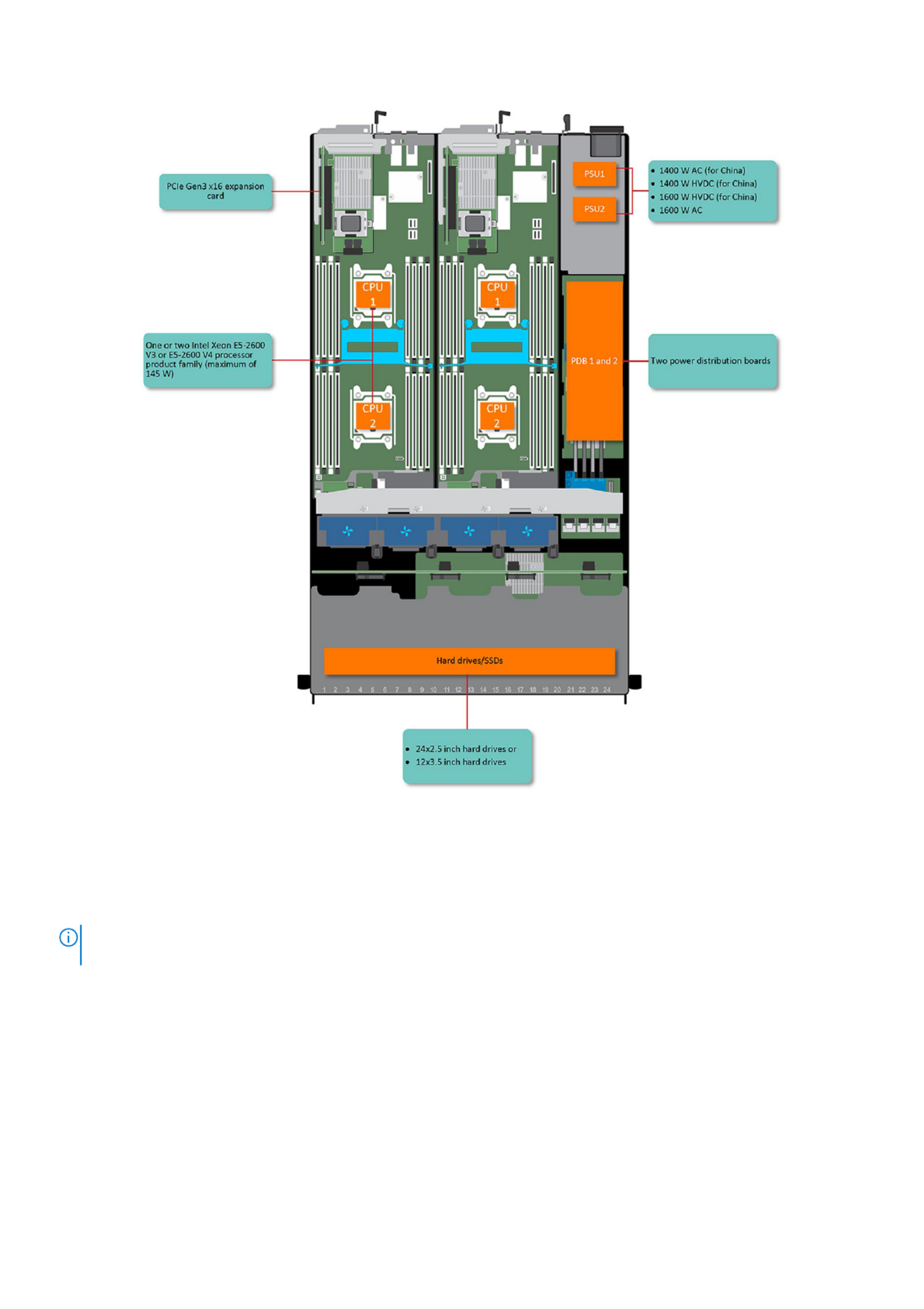
Figure 1. Supported configurations for C6320
Accessing system features during startup
The following keystrokes provide access to system features during startup.
NOTE: The hot keys of SAS or SATA card or PXE support are available in BIOS boot mode only. There is no hot key to boot
in the UEFI mode.
Keystroke Description
F2 Enters the System Setup program.
F11 Enters the BIOS Boot Manager.
F12 Starts Preboot eXecution Environment (PXE)/iSCSI boot.
Ctrl +C Enters the LSI 2008 SAS Mezzanine Card Configuration Utility. For more information, see the SAS
adapter documentation.
Ctrl+R Enters the PERC 9 Card Configuration Utility. For more information, see the documentation for your SAS
RAID card.
Dell PowerEdge C6320 product overview 9

Keystroke Description
Ctrl+Y Enters the MegaPCLI SAS RAID Management Tool.
Ctrl+S Enters the utility to configure onboard LAN settings for PXE boot. For more information, see the
documentation for your integrated LAN.
Ctrl+I Enters onboard SATA Controller’s Configuration Utility.
Ctrl+D Enters the Intel iSCSI setup menu.
Front panel features and indicators
Figure 2. Front panel − 3.5-inch x12 hard drives with four system boards (C6320 RAID card and onboard SATA
controller)
Figure 3. Front panel − 2.5-inch x24 hard drives with four system boards (C6320 RAID card and onboard SATA
controller)
NOTE: For more information about the direction details of the 2.5-inch hard drive expander configuration support, see the
HDD Zoning configuration tool at Dell.com/support.
Table 1. Front panel features and indicators
Item Indicator, button or connector Icon Description
1Power-on indicator or system state
indicator or power button for system
board 1
The power-on indicator turns to green when the
system power is on.
The power-on indicator turns to amber when the
system critical event occurs.
The power button controls the DC power supply output
to the system.
NOTE: When turning on the system, the video
monitor can take from several seconds to over two
minutes to display an image, depending on the
number and capacity of DIMMs installed in the
system.
NOTE: On ACPI-compliant operating systems
(OSs), turning off the system by using the power
button causes the system to perform a graceful
shutdown before power to the system is turned off.
3Power-on indicator or system state
indicator or power button for system
board 2
7Power-on indicator or system state
indicator or power button for system
board 4
9Power-on indicator or system state
indicator or power button for system
board 3
10 Dell PowerEdge C6320 product overview
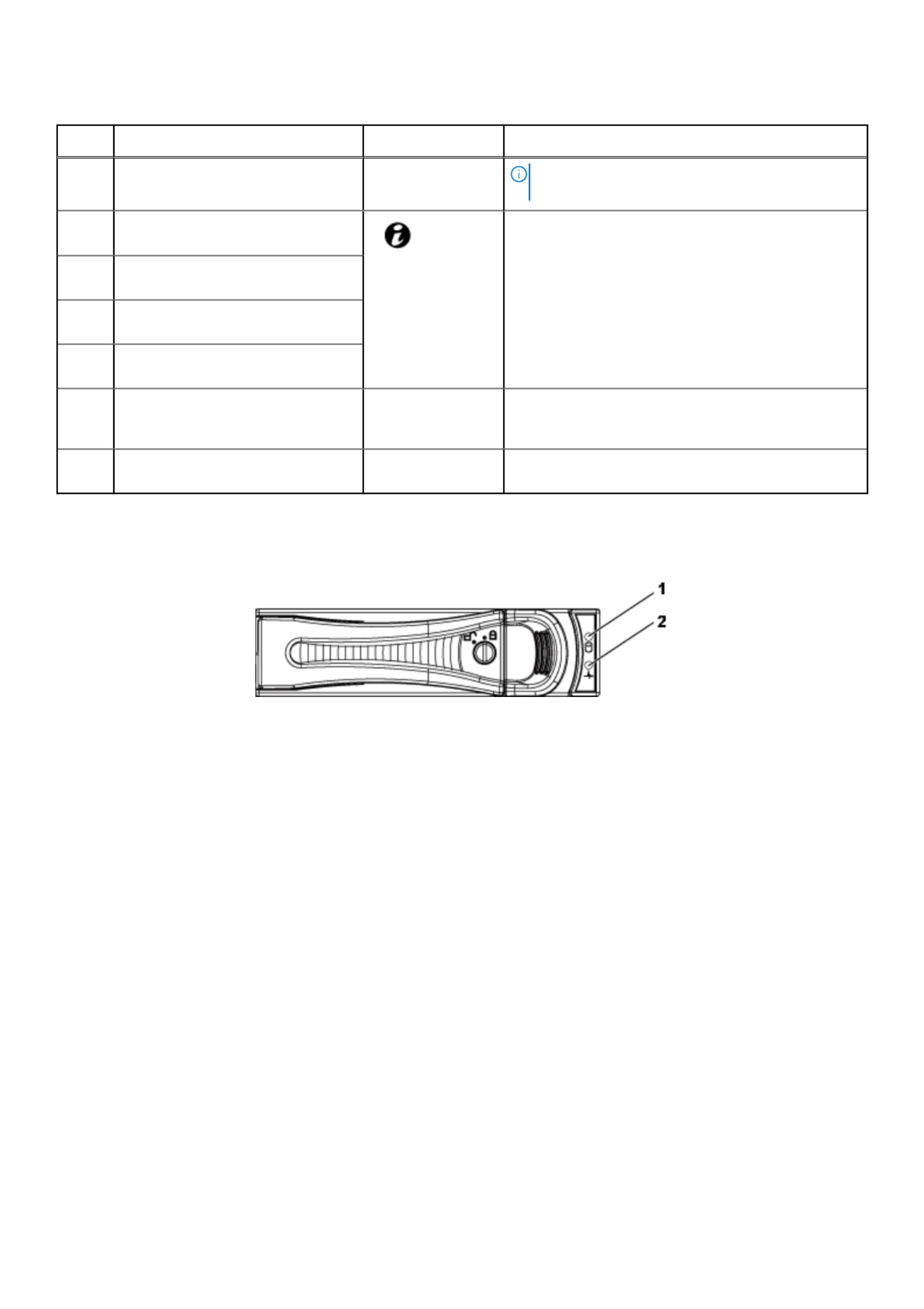
Table 1. Front panel features and indicators (continued)
Item Indicator, button or connector Icon Description
NOTE: To force an ungraceful shutdown, press and
hold the power button for 5 seconds.
2 System identification indicator or
button for system board 1
The identification button can be used to locate a
particular system and system board within a chassis.
When the button is pushed, the blue status indicator of
the system on the front and rear blinks until the button
is pushed again.
4 System identification indicator or
button for system board 2
6 System identification indicator or
button for system board 4
8 System identification indicator or
button for system board 3
5 Hard drives Up to 12 hot swappable 3.5-inch hard drives.
Up to 24 hot swappable 2.5-inch hard drives.
* Drive cover Applicable only for 2.5-inch hard drive systems. This is
not a usable drive slot.
Hard drive indicator patterns
Figure 4. 3.5-inch hard drive indicators
1
1
1
11.
.
.
.. hard drive activity indicator (green)
2
2
2
22.
.
.
.. hard drive status indicator (green and amber)
Dell PowerEdge C6320 product overview 11

Figure 5. 2.5-inch hard drive indicators
1
1
1
11.
.
.
.. hard drive status indicator (green and amber)
2
2
2
22.
.
.
.. hard drive activity indicator (green)
Table 2. Hard drive indicator patterns
Controller Hard drive type Function Activity LED Status LED
Green Green Amber
Onboard Controller SATA2 Drive on-line Off/Blinking when
active
On Off
Fail Off On Off
PERC 9/LSI 2008 SAS/SATA2 Slot Empty Off Off Off
Drive on-line/
Access
Blinking when
active
On Off
Drive identify/
prepare for
removal
Blinking when
active
On 250 ms
Off 250 ms
Off
Drive Failed Off Off On 150 ms
Off 150 ms
Drive Rebuild Blinking when
active
On 400 ms
Off 100 ms
Off
Predicted Failure
(SMART)
Blinking when
active
On 500 ms
Off 500 ms
Off 1000 ms
Off 500 ms
On 500 ms
Off 1000 ms
Rebuild Abort Off On 3000 ms
Off 9000 ms
Off 6000 ms
On 3000 ms
Off 000 ms
12 Dell PowerEdge C6320 product overview

Back panel features and indicators
Figure 6. Back panel with four system boards
Table 3. Back panel features and indicators
Item Indicator, button, or connector Icon Description
1 PSU 2 Up to 1400 W AC, 1600 W AC, or
1400 HVDC PSUs.
2 PSU 1 Up to 1400 W AC, 1600 W AC, or
1400 HVDC PSUs.
3 USB port Enables you to connect USB devices
to the system. The ports are USB
3.0-compliant.
4 Ethernet connector 10G NIC 1 connector.
5 Ethernet connector 10G NIC 2 connector.
6 Management port Dedicated management port.
7 USB to serial port Connects the system to a host.
8 VGA port Connects a VGA display to the
system.
9 Power button/power and system LED The power-on indicator glows green
when the system power is on.
The power-on indicator turns amber
when the system critical event
occurs.
The power button controls the DC
PSU output to the system.
NOTE: When turning on the
system, the video monitor can
take from several seconds to over
two minutes to display an image,
on the basis of the disk space
available in the system.
NOTE: On ACPI-compliant
operating systems, turning off the
system by using the power button
causes the system to perform a
Dell PowerEdge C6320 product overview 13

Table 3. Back panel features and indicators (continued)
Item Indicator, button, or connector Icon Description
graceful shutdown before the
system is turned off.
NOTE: To force an ungraceful
shutdown, press and hold the
power button for five seconds.
10 System identification indicator The management software of both
the systems and the identification
buttons on the front can cause the
indicator to flash blue to identify a
particular system and system board.
Indicators turn amber when the
system requires attention because of
an issue.
LAN indicator codes
Figure 7. LAN indicators on the QSFP carrier card
Figure 8. LAN indicators
1
1
1
11.
.
.
.. activity indicator
2
2
2
22.
.
.
.. link and network speed indicator
NOTE: The LED blink speed varies according to the traffic bandwidth.
Table 4. LAN indicator codes
Component Indicator Condition
Link and network speed indicator Solid amber Linking at 1 Gbps speed
Solid green Linking at 10 Gbps speed
14 Dell PowerEdge C6320 product overview

Table 4. LAN indicator codes (continued)
Component Indicator Condition
Activity indicator Blinking green Activity is present:
● Pre OS POST
● OS without driver
● OS with driver
Blinking at speed relative to packet
density.
Off No link/activity present
● D0 (uninitialized)
● D3 (cold)
● S4 (hibernation)
Figure 9. LAN indicators (management port)
1
1
1
11.
.
.
.. speed indicator
2
2
2
22.
.
.
.. link and activity indicator
Table 5. LAN indicators (management port)
Component Indicator Condition
Speed indicator Solid green Linking at 1 Gbps speed
Solid amber Linking at 10/100 Mbps speed
Link and activity indicator Off No access or Idle
Blinking green LAN access or Link up
Power and system board indicator codes
The LEDs on the system front panel and back panel display status codes during system startup and operation. For location of
the LEDs on the front panel, see the Front panel features and indicators section. For location of the LEDs on the back panel, see
the Back panel features and indicators section.
Table 6. Status indicator codes
Component Indicator Condition
Power-on indicator (A bi-color
LED on power button)
Green Solid Power On (S0)
Amber Off
Green Off BMC critical condition event in Power Off mode (S4/S5)
Amber Blinking
Green Off BMC critical condition event in Power On mode (S0)
Amber Blinking
Dell PowerEdge C6320 product overview 15
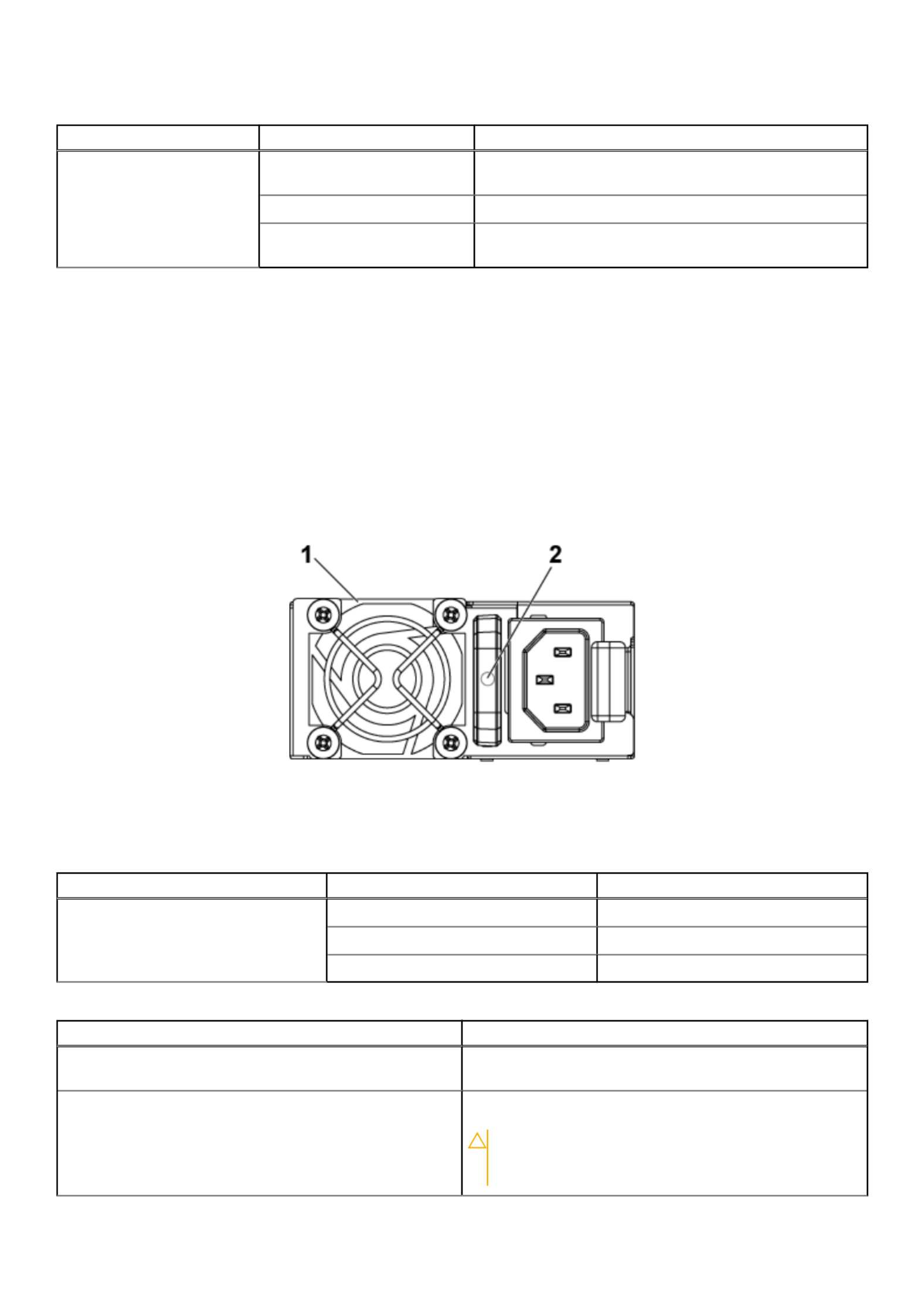
Table 6. Status indicator codes (continued)
Component Indicator Condition
System identification indicator Steady blue IPMI using Chassis Identify Command On or ID Button Press
ID On
Blinking blue Only IPMI using Chassis Identify Command Blink On
Off IPMI using Chassis Identify Command Off or ID Button
Press ID Off
Related references
Front panel features and indicators on page 10
Back panel features and indicators on page 13
Power Supply Unit indicator codes
Each AC power supply unit (PSU) has an illuminated translucent handle that indicates whether power is present or whether a
power fault has occurred.
1400 W AC or HVDC Power supply units
Figure 10. PSU status indicators
1
1
1
11.
.
.
.. PSU
2
2
2
22.
.
.
.. AC power indicator
Table 7. 1400 W AC/1400 W HVDC PSUs indicators
Component Indicator Indicator
AC or DC power indicator Solid amber Fault (fault of any kind)
Solid green DC_OK (power good)
Blinking green AC_OK
Table 8. 1400 W AC or HVDC PSU indicators
Power Indicator Pattern Condition
Green A valid power source is connected to the PSU and the PSU is
operational.
Flashing green When the PSU firmware is being updated, the PSU LED
flashes green.
CAUTION: Do not disconnect the power cord or
unplug the PSU when updating firmware. If firmware
update is interrupted, the PSUs will not function.
16 Dell PowerEdge C6320 product overview

Table 8. 1400 W AC or HVDC PSU indicators (continued)
Power Indicator Pattern Condition
You must roll back the PSU firmware by using Dell
Lifecycle Controller. For more information, see Dell
Lifecycle Controller User’s Guide at Dell.com/
idracmanuals.
Flashing green and turns off When hot-adding a PSU, the PSU LED flashes green five
times at 4 Hz rate and turns off. This indicates that there is a
PSU mismatch with respect to efficiency, feature set, health
status, and supported voltage.
NOTE: Ensure that both the PSUs are of the same
capacity.
NOTE: Mixing PSUs from previous generations of Dell
PowerEdge servers can result in a PSU mismatch
condition and failure to turn the system on.
Flashing amber Indicates a problem with the PSU.
CAUTION: When correcting a PSU mismatch, replace
only the PSU with the flashing indicator. Swapping
the other PSU to make a matched pair can result in
an error condition and unexpected system shutdown.
To change from a High Output configuration to a
Low Output configuration or vice versa, you must
turn off the system.
CAUTION: If two PSUs are used, they must be of the
same type and have the same maximum output
power.
CAUTION: Combining AC and DC PSUs is not
supported and triggers a mismatch.
Not lit Power is not connected.
1600 W AC or HVDC Power supply unit
Figure 11. Power supply unit (PSU ) status indicator
1
1
1
11.
.
.
.. PSU
2
2
2
22.
.
.
.. AC power indicator
Dell PowerEdge C6320 product overview 17

Table 9. 1600 W AC/1600 W HVDC PSU indicators
Component Indicator Condition
AC power indicator Solid amber Standby mode with Fan Lock for 15
seconds.
Standby mode with OTP range
Active mode with +12 V DC Fault
Active mode with Fan Lock for 15
seconds.
Solid green DC_OK (power good)
Blinking green Standby mode normal
Off Unit without AC power
Baseboard Management Controller (BMC) heart beat
LED
The system board provides BMC heart beat LED (CR17) for BMC debugging. The BMC heart beat LED is green. When the
power is connected, the LED is on. When BMC firmware is ready, the BMC heart beat LED blinks.
Figure 12. BMC heart beat LED on the C6320 system board
1
1
1
11.
.
.
.. BMC heart beat LED
System configuration limitations by Intel Xeon
processor E5-2600 v3 and E5-2600 v4 product family
NOTE: Certain system hardware configurations may require reductions in the upper temperature limits.
NOTE: System performance may be impacted when operating above 30°C or with a fan fault.
Table 10. Configuration restrictions with Intel Xeon processor E5-2600 v3 and E5-2600 v4 product
family
Processor 3.5-inch hard drive chassis 2.5-inch hard drive chassis
55 W
E5-2630L v3
E5-2630L v4
No configuration restrictions No configuration restrictions
18 Dell PowerEdge C6320 product overview

Table 10. Configuration restrictions with Intel Xeon processor E5-2600 v3 and E5-2600 v4 product
family (continued)
Processor 3.5-inch hard drive chassis 2.5-inch hard drive chassis
60 W
E5-2650L v3
65 W
E5-2650L v4
85 W
E5-2603 v3
E5-2630 v3
E5-2620 v3
E5-2630 v4
E5-2623 v4
E5-2620 v4
E5-2609 v4
E5-2603 v4
90 W
E5-2640 v3
E5-2640 v4
105 W
E5-2660 v3
E5-2650 v3
E5-2623 v3
E5-2660 v4
E5-2650 v4
120 W
E5-2683 v3
E5-2685 v3
E5-2695 v3
E5-2680 v3
E5-2670 v3
E5-2695 v4
E5-2683 v4
E5-2680 v4
PERC H730 is not supported PERC H730 is not supported
135 W (16 cores and 12 cores)
E5-2698 v3
E5-2690 v3
PERC H730/H330 are not supported
PERC H730/H330 are not supported
135 W (14 cores and 20 cores)
E5-2698 v4
E5-2690 v4
PERC H730/330 are not supported
Dell PowerEdge C6320 product overview 19

Table 10. Configuration restrictions with Intel Xeon processor E5-2600 v3 and E5-2600 v4 product
family (continued)
Processor 3.5-inch hard drive chassis 2.5-inch hard drive chassis
135 W (8 cores) and 145 W
E5-2667 v3
● PERC H730/H330 are not supported
● Restricted to total 8 hard drives
145 W (14 cores)
E5-2697 v3
145 W (18 cores)
E5-2699 v3
135W (8/6/4 cores) and 145W
(22/18/16 cores)
E5-2667 v4
E5-2643 v4
E5-2637 v4
E5-2699 v4
E5-2697 v4
E5-2697A v4
● PERC H730/H330 are not supported
● Restricted to total 8 hard drives
PERC H730/330 are not supported
Table 11. Fresh air cooling configuration restrictions
Processor 3.5-inch hard drive chassis 2.5-inch hard drive chassis
55W
E5-2630L v4
PERC H730 is not supported PERC H730 is not supported
65W
E5-2650L v4
85 W
E5-2630 v3
E5-2620 v3
E5-2603 v3
E5-2630 v4
E5-2623 v4
E5-2620 v4
E5-2609 v4
E5-2603 v4
90 W
E5-2640 v3
E5-2640 v4
105 W
E5-2660 v3
E5-2650 v3
E5-2623 v3
E5-2660 v4
20 Dell PowerEdge C6320 product overview

Table 11. Fresh air cooling configuration restrictions (continued)
Processor 3.5-inch hard drive chassis 2.5-inch hard drive chassis
E5-2650 v4
120 W
E5-2695 v3
E5-2680 v3
E5-2670 v3
E5-2695 v4
E5-2683 v4
E5-2680 v4
Support maximum 8x hard drives
PERC H730/H330 are not supported
Support maximum 12x hard
drives
PERC H730/H330 are not
supported
135 W (16 cores and 12 cores)
E5-2698 v3
E5-2690 v3
Not supported Not supported
135 W (20 cores and 14 cores)
E5-2698 v4
E5-2690 v4
135 W (8 cores) and 145 W
E5-2699 v3
145 W (14 cores)
E5-2697 v3
135W (8/6/4 cores) and 145W (22/18/16
cores)
E5-2667 v4
E5-2643 v4
E5-2637 v4
E5-2699 v4
E5-2697 v4
E5-2697A v4
Locating your system Service Tag
Your system is identified by a unique Express Service Code and Service Tag number. The Express Service Code is found on the
front of the system and Service Tag is found on the front of the system. Alternatively, the information may be on a sticker on
the chassis of the system. This information is used by Dell to route support calls to the appropriate personnel. The Service Tag
locations on the chassis are as follows:
Dell PowerEdge C6320 product overview 21

Figure 13. Service Tag location
Figure 14. Service Tag location on the left front panel
Figure 15. Service Tag location on the chassis
Hard drives under warranties are linked to each node with an appropriate service tag. The linked hard drives with the node is
shown in the below figure.
22 Dell PowerEdge C6320 product overview
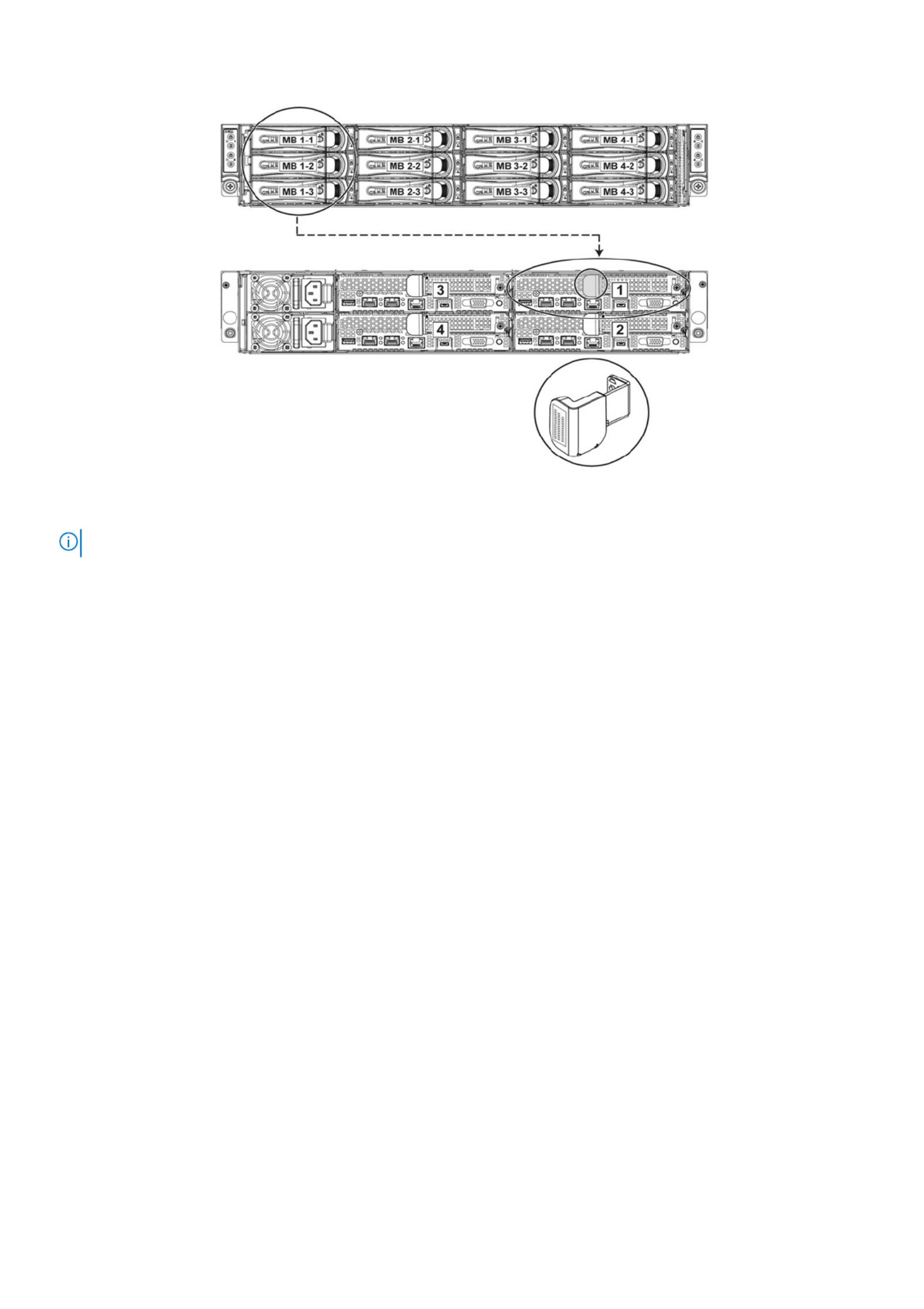
Figure 16. Service Tag linkage
NOTE: Hard drives that are under warranty are linked to the appropriate Service Tag of the node.
Dell PowerEdge C6320 product overview 23

Documentation resources
This section provides information about the documentation resources for your system.
To view the document that is listed in the documentation resources table:
● From the Dell EMC support site:
1
1
1
11.
.
.
.. Click the documentation link that is provided in the Location column in the table.
2
2
2
22.
.
.
.. Click the required product or product version.
NOTE: To locate the product name and model, see the front of your system.
3
3
3
33.
.
.
.. On the Product Support page, click .Manuals & documents
● Using search engines:
○ Type the name and version of the document in the search box.
Table 12. Additional documentation resources for your system
Task Document Location
Setting up your
system
For information about installing the
system into a rack, see the Rack
documentation included with your
rack solution or the Getting
Started Guide document that is
shipped with your system.
www.dell.com/poweredgemanuals
Configuring your
system
For information about the iDRAC
features, configuring and logging
in to iDRAC, and managing your
system remotely, see the
Integrated Dell Remote Access
Controller User's Guide.
For information about
understanding Remote Access
Controller Admin (RACADM)
subcommands and supported
RACADM interfaces, see the
RACADM CLI Guide for iDRAC.
For information about Redfish and
its protocol, supported schema,
and Redfish Eventing are
implemented in iDRAC, see the
Redfish API Guide.
For information about iDRAC
property database group and
object descriptions, see the
Attribute Registry Guide.
www.dell.com/poweredgemanuals
For information about earlier
versions of the iDRAC documents,
see the iDRAC documentation.
To identify the version of iDRAC
available on your system, on the
iDRAC web interface, click >?
About.
www.dell.com/idracmanuals
2
24 Documentation resources

Table 12. Additional documentation resources for your system (continued)
Task Document Location
For information about installing the
operating system, see the
operating system documentation.
www.dell.com/
operatingsystemmanuals
For information about updating
drivers and firmware, see the
Methods to download firmware
and drivers section in this
document.
www.dell.com/support/drivers
Managing your
system
For information about systems
management software offered by
Dell, see the Dell OpenManage
Systems Management Overview
Guide.
www.dell.com/poweredgemanuals
For information about setting up,
using, and troubleshooting
OpenManage, see the Dell
OpenManage Server Administrator
User’s Guide.
www.dell.com/
openmanagemanuals >
OpenManage Server Administrator
For information about installing,
using, and troubleshooting Dell
OpenManage Essentials, see the
Dell OpenManage Essentials User’s
Guide.
www.dell.com/
openmanagemanuals >
OpenManage Essentials
For information about installing,
using, and troubleshooting Dell
OpenManage Enterprise, see the
Dell OpenManage Enterprise
User’s Guide.
www.dell.com/
openmanagemanuals >
OpenManage Enterprise
For information about installing
and using Dell SupportAssist, see
the Dell EMC SupportAssist
Enterprise User’s Guide.
https://www.dell.com/
serviceabilitytools
For information about partner
programs enterprise systems
management, see the
OpenManage Connections
Enterprise Systems Management
documents.
www.dell.com/
openmanagemanuals
Working with the Dell PowerEdge
RAID controllers
For information about
understanding the features of the
Dell PowerEdge RAID controllers
(PERC), Software RAID
controllers, or BOSS card and
deploying the cards, see the
Storage controller documentation.
www.dell.com/
storagecontrollermanuals
Understanding event
and error messages
For information about the event
and error messages that are
generated by the system firmware
and agents that monitor system
components, see the Error Code
Lookup.
www.dell.com/qrl
Troubleshooting your
system
For information about identifying
and troubleshooting the
www.dell.com/poweredgemanuals
Documentation resources 25

Technical specifications
The technical and environmental specifications of your system are outlined in this section.
Topics:
• Chassis dimensions
• Processor specifications
• PSU specifications
• System battery specifications
• Memory specifications
• Environmental specifications
Chassis dimensions
Figure 17. Chassis dimensions of PowerEdge C6300 enclosure
Table 13. Dimensions of the Dell PowerEdge C6300 enclosure
Xa Xb Y Za (with
bezel)
Za (without
bezel)
Zb Zc
482.3 mm 448.0 mm 86.8 mm N/A 41.4 mm 762.1 mm 795.9 mm
3
Technical specifications 27

Processor specifications
Dell PowerEdge C6320 supports up to two Intel Xeon E5-2600 v3 or Intel Xeon E5-2600 v4 product family processors in four
independent servers.
PSU specifications
Dell PowerEdge C6320 system supports up to two AC or HVDC power supply units (PSUs). Dell PowerEdge C6320 does not
support a mixed installation of 1400 W and 1600 W power supply units. The 1400 W and 1600 W power supply units are hot
swappable, and supports hot swap in any condition if the system has the power throttling feature enabled.
Table 14. PSU specifications
PSU Heat dissipation
(maximum)
Frequency Voltage Maximum input
current
Maximum inrush
current (peak)
1400 W AC 5220.763 BTU/hr 50/60 Hz 200-240 V AC 9 A Initial inrush
current cannot
exceed 55 A
(peak).
Secondary inrush
current cannot
exceed 25 A
(peak).
1600 W AC 5966.586 BTU/hr 50/60 Hz 100-120 V AC
200-240 V AC
12 A
10 A
Initial inrush
current and
secondary inrush
current cannot
exceed 35 A
(peak).
1400 W HVDC (for
China only)
5220.763 BTU/hr – 240 V DC 9 A Initial inrush
current cannot
exceed 55 A
(peak).
Secondary inrush
current cannot
exceed 25 A
(peak).
System battery specifications
Dell PowerEdge C6320 system supports CR 2032 3.0-V lithium coin cell battery.
Memory specifications
Dell PowerEdge C6320 system supports DDR4 registered DIMMs (RDIMMs).
Table 15. Memory specifications
Memory module
sockets
Architecture Memory capacity Minimum RAM Maximum RAM
Sixteen 288-pin 1600 MT/s, 1866 MT/s,
2133 MT/s, or 2400
MT/s DDR4 Registered
DIMMs with support for
8 GB, 16 GB, and 32 GB
dual-rank
16 GB Up to 512 GB
28 Technical specifications

Table 15. Memory specifications
Memory module
sockets
Architecture Memory capacity Minimum RAM Maximum RAM
advanced ECC or
memory optimized
operation
Environmental specifications
NOTE: For additional information about environmental measurements for specific system configurations, see Dell.com/
environmental_datasheets
Table 16. Temperature specifications
Temperature Specifications
Storage –40° to 65°C (–40° to 149°F) with a maximum temperature
gradation of 20°C per hour.
Continuous operation (for altitude less than 950 m or 3117 ft) 10°C to 35°C (50°F to 95°F) with no direct sunlight on the
equipment.
Fresh air For information on fresh air, see Expanded Operating
Temperature section.
Maximum temperature gradient (operating and storage) 20°C/h (36°F/h)
Table 17. Expanded operating temperature specifications
Expanded operating temperature Specifications
NOTE: When operating in the expanded temperature range, system performance may be impacted.
NOTE: When operating in the expanded temperature range, ambient temperature warnings may be reported on the LCD
and in the System Event Log.
Continuous operation 5°C to 40°C at 5% to 85% RH with 29°C dew point.
NOTE: Outside the standard operating temperature (10°C
to 35°C), the system can operate down to 5°C or up to
40°C.
For temperatures between 35°C and 40°C, de-rate maximum
allowable dry bulb temperature by 1°C per 175 m above 950 m
(1°F per 319 ft).
≤ 1% of annual operating hours –5°C to 45°C at 5% to 90% RH with 26°C dew point.
NOTE: Outside the standard operating temperature (10°C
to 35°C), the system can operate down to –5°C or up to
45°C for a maximum of 1% of its annual operating hours.
For temperatures between 40°C and 45°C, de-rate maximum
allowable dry bulb temperature by 1°C per 125 m above 950 m
(1°F per 228 ft).
Expanded operating temperature restrictions ● Do not perform a cold startup below 5 °C.
● Maximum 120 W processor is supported.
● Maximum of eight 3.5 inch or twelve 2.5 inch hard drives
are supported with 120 W processor.
The following do not support the expanded operating
temperature range:
Technical specifications 29

Table 17. Expanded operating temperature specifications (continued)
Expanded operating temperature Specifications
● Dell PowerEdge RAID Controller (PERC) H730/H730P
cards with CPU TDP ≥ 85 W.
● Dell PowerEdge RAID Controller (PERC) H330 card with
CPU TDP ≥ 120 W.
● Non Dell-qualified peripheral cards and/or peripheral cards
greater than 25 W are not supported.
Table 18. Relative humidity specifications
Relative humidity Specifications
Operating 20% to 80% (noncondensing) with a maximum humidity
gradation of 10% per hour
Storage 5% to 95% (non-condensing)
Table 19. Maximum vibration specifications
Maximum vibration Specifications
Operating 0.26 Grms at 5–350 Hz
Storage 1.88 Grms at 10–500 Hz for 15 minutes
Table 20. Maximum shock specifications
Maximum shock Specifications
Operating One shock pulse in the positive z axis (one pulse on each side
of the system) of 31 G for 2.6 ms in the operational
orientation.
Storage Six consecutively executed shock pulses in the positive and
negative x, y, and z axes (one pulse on each side of the
system) of 71 G for up to 2 ms
Six consecutively executed shock pulses in the positive and
negative x, y, and z axes (one pulse on each side of the
system) of 27 G faired square wave pulse with velocity
change at 235 inches per second (597 centimeters per
second)
Table 21. Maximum altitude specifications
Maximum altitude Specifications
Operating -15.2 m to 3,048 m (-50 to 10,000 ft.)
Storage -15.2 m to 10,668 m (-50 to 35,000 ft.)
Table 22. Airborne contaminant level specification
Specifications
Airborne contaminant level (Class) G1 as defined by ISA-S71.04-1985
30 Technical specifications

NOTE: Ensure that you change the default user name and password after setting up the iDRAC IP address.
Log in to iDRAC
You can log in to iDRAC as:
● iDRAC user
● Microsoft Active Directory user
● Lightweight Directory Access Protocol (LDAP) user
The default user name and password are and . You can also log in by using Single Sign-On or Smart Card.root calvin
NOTE: You must have iDRAC credentials to log in to iDRAC.
For more information about logging in to iDRAC and iDRAC licenses, see the latest Integrated Dell Remote Access Controller
User's Guide at .Dell.com/idracmanuals
Options to install the operating system
If the system is shipped without an operating system, install the supported operating system by using one of the following
resources:
Table 23. Resources to install the operating system
Resources Location
Dell Systems Management Tools and Documentation media Dell.com/operatingsystemmanuals
Dell Lifecycle Controller Dell.com/idracmanuals
Dell OpenManage Deployment Toolkit Dell.com/openmanagemanuals
Dell certified VMware ESXi Dell.com/virtualizationsolutions
Supported operating systems on Dell PowerEdge systems Dell.com/ossupport
Installation and How-to videos for supported operating
systems on Dell PowerEdge systems
Supported Operating Systems for Dell PowerEdge Systems
Methods to download firmware and drivers
You can download the firmware and drivers by using any of the following methods:
Table 24. Firmware and drivers
Methods Location
From the Dell Support site Global Technical Support
Using Dell Remote Access Controller Lifecycle Controller
(iDRAC with LC)
Dell.com/idracmanuals
Using Dell Repository Manager (DRM) > OpenManage DeploymentDell.com/openmanagemanuals
Toolkit
Using Dell OpenManage Essentials (OME) > OpenManage DeploymentDell.com/openmanagemanuals
Toolkit
Using Dell Server Update Utility (SUU) > OpenManage DeploymentDell.com/openmanagemanuals
Toolkit
Using Dell OpenManage Deployment Toolkit (DTK) > OpenManage DeploymentDell.com/openmanagemanuals
Toolkit
32 Initial system setup and configuration

Downloading the drivers and firmware
Dell EMC recommends that you download and install the latest BIOS, drivers, and systems management firmware on your
system.
Prerequisites
Ensure that you clear the web browser cache before downloading the drivers and firmware.
Steps
1
1
1
11.
.
.
.. Go to .Dell.com/support/drivers
2
2
2
22.
.
.
.. In the section, type the Service Tag of your system in the Drivers & Downloads Service Tag or Express Service Code
box, and then click .Submit
NOTE: If you do not have the Service Tag, select to allow the system to automatically detect yourDetect My Product
Service Tag, or in , navigate to your product.General support
3
3
3
33.
.
.
.. Click .Drivers & Downloads
The drivers that are applicable to your selection are displayed.
4
4
4
44.
.
.
.. Download the drivers to a USB drive, CD, or DVD.
Initial system setup and configuration 33

Pre-operating system management
applications
You can manage basic settings and features of a system without booting to the operating system by using the system firmware.
Topics:
• Options to manage the pre-operating system applications
• System Setup
• Dell Lifecycle Controller
• Boot Manager
• PXE boot
Options to manage the pre-operating system
applications
Your system has the following options to manage the pre-operating system applications:
● System Setup
● Boot Manager
● Dell Lifecycle Controller
● Preboot Execution Environment (PXE)
Related concepts
System Setup on page 34
Related references
Boot Manager on page 60
Dell Lifecycle Controller on page 59
PXE boot on page 61
System Setup
By using the screen, you can configure the BIOS settings, iDRAC settings, and device settings of your system.System Setup
NOTE: Help text for the selected field is displayed in the graphical browser by default. To view the help text in the text
browser, press F1.
You can access system setup by using two methods:
● Standard graphical browser — The browser is enabled by default.
● Text browser — The browser is enabled by using Console Redirection.
Related references
System Setup details on page 35
Related tasks
Viewing System Setup on page 35
5
34 Pre-operating system management applications

Viewing System Setup
To view the screen, perform the following steps:System Setup
Steps
1
1
1
11.
.
.
.. Turn on, or restart your system.
2
2
2
22.
.
.
.. Press F2 immediately after you see the following message:
F2 = System Setup
NOTE: If your operating system begins to load before you press F2, wait for the system to finish booting, and then
restart your system and try again.
Related concepts
System Setup on page 34
Related references
System Setup details on page 35
System Setup details
The screen details are explained as follows:System Setup Main Menu
Option Description
System BIOS Enables you to configure BIOS settings.
iDRAC Settings Enables you to configure iDRAC settings.
The iDRAC settings utility is an interface to set up and configure the iDRAC parameters by using UEFI
(Unified Extensible Firmware Interface). You can enable or disable various iDRAC parameters by using the
iDRAC settings utility. For more information about this utility, see Integrated Dell Remote Access
Controller User’s Guide at .Dell.com/idracmanuals
Device Settings Enables you to configure device settings.
Related concepts
System Setup on page 34
System BIOS on page 35
Related references
iDRAC Settings utility on page 58
Device Settings on page 59
Related tasks
Viewing System Setup on page 35
System BIOS
You can use the screen to edit specific functions such as boot order, system password, setup password, set theSystem BIOS
RAID mode, and enable or disable USB ports.
Related concepts
Boot Settings on page 44
Pre-operating system management applications 35

Network Settings on page 46
System Information on page 37
Memory Settings on page 38
Processor Settings on page 40
SATA Settings on page 42
Integrated Devices on page 48
Serial Communication on page 50
System Profile Settings on page 52
Miscellaneous Settings on page 57
Related references
iDRAC Settings utility on page 58
Device Settings on page 59
Related tasks
System BIOS Settings details on page 36
Viewing System BIOS on page 36
Viewing System BIOS
To view the screen, perform the following steps:System BIOS
Steps
1
1
1
11.
.
.
.. Turn on, or restart your system.
2
2
2
22.
.
.
.. Press F2 immediately after you see the following message:
F2 = System Setup
NOTE: If your operating system begins to load before you press F2, wait for the system to finish booting, and then
restart your system and try again.
3
3
3
33.
.
.
.. On the screen, click .System Setup Main Menu System BIOS
Related concepts
System BIOS on page 35
Related tasks
System BIOS Settings details on page 36
System BIOS Settings details
About this task
The screen details are explained as follows:System BIOS Settings
Option Description
System
Information
Specifies information about the system such as the system model name, BIOS version, and Service Tag.
Memory Settings Specifies information and options related to the installed memory.
Processor
Settings
Specifies information and options related to the processor such as speed and cache size.
SATA Settings Specifies options to enable or disable the integrated SATA controller and ports.
36 Pre-operating system management applications

Option Description
Boot Settings Specifies options to specify the boot mode (BIOS or UEFI). Enables you to modify UEFI and BIOS boot
settings.
Network Settings Specifies options to change the network settings.
Integrated
Devices
Specifies options to manage integrated device controllers and ports and specify related features and
options.
Serial
Communication
Specifies options to manage the serial ports and specify related features and options.
System Profile
Settings
Specifies options to change the processor power management settings, memory frequency, and so on.
System Security Specifies options to configure the system security settings, such as system password, setup password,
Trusted Platform Module (TPM) security. It also manages the power and NMI buttons on the system.
Miscellaneous
Settings
Specifies options to change the system date, time, and so on.
Related concepts
System BIOS on page 35
Related tasks
Viewing System BIOS on page 36
System Information
You can use the screen to view system properties such as Service Tag, system model name, and the BIOSSystem Information
version.
Related concepts
System BIOS on page 35
Related tasks
System Information details on page 38
Viewing System Information on page 37
Viewing System Information
To view the screen, perform the following steps:System Information
Steps
1
1
1
11.
.
.
.. Turn on, or restart your system.
2
2
2
22.
.
.
.. Press F2 immediately after you see the following message:
F2 = System Setup
NOTE: If your operating system begins to load before you press F2, wait for the system to finish booting, and then
restart your system and try again.
3
3
3
33.
.
.
.. On the screen, click .System Setup Main Menu System BIOS
4
4
4
44.
.
.
.. On the screen, click .System BIOS System Information
Related concepts
System Information on page 37
Pre-operating system management applications 37

Related tasks
System Information details on page 38
System Information details
About this task
The screen details are explained as follows:System Information
Option Description
System Model
Name
Specifies the system model name.
System BIOS
Version
Specifies the BIOS version installed on the system.
System
Management
Engine Version
Specifies the current version of the Management Engine firmware.
System Service
Tag
Specifies the system Service Tag.
System
Manufacturer
Specifies the name of the system manufacturer.
System
Manufacturer
Contact
Information
Specifies the contact information of the system manufacturer.
System CPLD
Version
Specifies the current version of the system complex programmable logic device (CPLD) firmware.
UEFI Compliance
Version
Specifies the UEFI compliance level of the system firmware.
Related concepts
System Information on page 37
Related tasks
System Information details on page 38
Viewing System Information on page 37
Memory Settings
You can use the screen to view all the memory settings and enable or disable specific memory functions,Memory Settings
such as memory testing and node interleaving.
Related concepts
System BIOS on page 35
Related tasks
Memory Settings details on page 39
Viewing Memory Settings on page 39
38 Pre-operating system management applications

Viewing Memory Settings
To view the screen, perform the following steps:Memory Settings
Steps
1
1
1
11.
.
.
.. Turn on, or restart your system.
2
2
2
22.
.
.
.. Press F2 immediately after you see the following message:
F2 = System Setup
NOTE: If your operating system begins to load before you press F2, wait for the system to finish booting, and then
restart your system and try again.
3
3
3
33.
.
.
.. On the screen, click .System Setup Main Menu System BIOS
4
4
4
44.
.
.
.. On the screen, click .System BIOS Memory Settings
Related concepts
Memory Settings on page 38
Related tasks
Memory Settings details on page 39
Memory Settings details
About this task
The screen details are explained as follows:Memory Settings
Option Description
System Memory
Size
Specifies the memory size in the system.
System Memory
Type
Specifies the type of memory installed in the system.
System Memory
Speed
Specifies the memory speed.
System Memory
Voltage
Specifies the memory voltage.
Video Memory Specifies the amount of video memory.
System Memory
Testing
Specifies whether the memory tests are run during system boot. Options are and . ThisEnabled Disabled
option is set to by default.Disabled
Memory
Operating Mode
Specifies the memory operating mode. The available option is .Optimizer Mode
Node Interleaving EnabledSpecifies if the Non-Uniform Memory Architecture (NUMA) is supported. If this field is set to ,
memory interleaving is supported if a symmetric memory configuration is installed. If the field is set to
Disabled, the system supports NUMA (asymmetric) memory configurations. This option is set to
Disabled by default.
Snoop Mode Home Snoop Early SnoopSpecifies the Snoop Mode options. The Snoop Mode options available are , ,
Cluster on Die Opportunist Snoop Broadcast Early Snoop, and . This option is set to by default. This
field is available only when the is set to .Node Interleaving Disabled
Related concepts
Memory Settings on page 38
Pre-operating system management applications 39

Related tasks
Viewing Memory Settings on page 39
Processor Settings
You can use the screen to view the processor settings, and perform specific functions such as enablingProcessor Settings
virtualization technology, hardware prefetcher, and logical processor idling.
Related concepts
System BIOS on page 35
Related tasks
Processor Settings details on page 40
Viewing Processor Settings on page 40
Viewing Processor Settings
To view the screen, perform the following steps:Processor Settings
Steps
1
1
1
11.
.
.
.. Turn on, or restart your system.
2
2
2
22.
.
.
.. Press F2 immediately after you see the following message:
F2 = System Setup
NOTE: If your operating system begins to load before you press F2, wait for the system to finish booting, and then
restart your system and try again.
3
3
3
33.
.
.
.. On the screen, click .System Setup Main Menu System BIOS
4
4
4
44.
.
.
.. On the screen, click .System BIOS Processor Settings
Related concepts
Processor Settings on page 40
Related tasks
Processor Settings details on page 40
Processor Settings details
About this task
The screen details are explained as follows:Processor Settings
Option Description
Logical
Processor
Enables or disables the logical processors and displays the number of logical processors. If this option is
set to , the BIOS displays all the logical processors. If this option is set to , the BIOSEnabled Disabled
displays only one logical processor per core. This option is set to by default.Enabled
QPI Speed Enables you to control QuickPath Interconnect data rate settings.
Alternate RTID
(Requestor
Transaction ID)
Setting
Modifies Requestor Transaction IDs, which are QPI resources. This option is set to by default.Disabled
NOTE: Enabling this option may negatively impact the overall system performance.
40 Pre-operating system management applications

Option Description
Virtualization
Technology
Enables or disables the additional hardware capabilities provided for virtualization. This option is set to
Enabled by default.
Address
Translation
Service (ATS)
Defines the Address Translation Cache (ATC) for devices to cache the DMA transactions. This option
provides an interface between CPU and DMA Memory Management to a chipset's Address Translation
and Protection Table to translate DMA addresses to host addresses. This option is set to byEnabled
default.
Adjacent Cache
Line Prefetch
Optimizes the system for applications that need high utilization of sequential memory access. This option
is set to by default. You can disable this option for applications that need high utilization ofEnabled
random memory access.
Hardware
Prefetcher
Enables or disables the hardware prefetcher. This option is set to by default.Enabled
DCU Streamer
Prefetcher
Enables or disables the Data Cache Unit (DCU) streamer prefetcher. This option is set to byEnabled
default.
DCU IP
Prefetcher
Enables or disables the Data Cache Unit (DCU) IP prefetcher. This option is set to by default.Enabled
Logical
Processor Idling
Enables you to improve the energy efficiency of a system. It uses the operating system core parking
algorithm and parks some of the logical processors in the system which in turn allows the corresponding
processor cores to transition into a lower power idle state. This option can only be enabled if the
operating system supports it. It is set to by default.Disabled
Configurable TDP Enables you to reconfigure the processor Thermal Design Power (TDP) levels during POST based on the
power and thermal delivery capabilities of the system. TDP verifies the maximum heat the cooling system
is needed to dissipate. This option is set to by default.Nominal
NOTE: This option is only available on certain stock keeping units (SKUs) of the processors.
X2Apic Mode Enables or disables the X2Apic mode.
Number of Cores
per Processor
Controls the number of enabled cores in each processor. This option is set to by default.All
Processor 64-bit
Support
Specifies if the processor(s) support 64-bit extensions.
Processor Core
Speed
Specifies the maximum core frequency of the processor.
Process Bus
Speed
Displays the bus speed of the processor.
NOTE: The processor bus speed option displays only when both processors are installed.
Processor 1 NOTE: Depending on the number of CPUs, there may be up to four processors listed.
The following settings are displayed for each processor installed in the system:
Option Description
Family-Model-
Stepping
Specifies the family, model, and stepping of the processor as defined by Intel.
Brand Specifies the brand name.
Level 2 Cache Specifies the total L2 cache.
Level 3 Cache Specifies the total L3 cache.
Number of Cores Specifies the number of cores per processor.
Related concepts
Processor Settings on page 40
Pre-operating system management applications 41

Related tasks
Viewing Processor Settings on page 40
SATA Settings
You can use the screen to view the SATA settings of SATA devices and enable RAID on your system.SATA Settings
Related concepts
System BIOS on page 35
Related tasks
SATA Settings details on page 42
Viewing SATA Settings on page 42
Viewing SATA Settings
To view the screen, perform the following steps:SATA Settings
Steps
1
1
1
11.
.
.
.. Turn on, or restart your system.
2
2
2
22.
.
.
.. Press F2 immediately after you see the following message:
F2 = System Setup
NOTE: If your operating system begins to load before you press F2, wait for the system to finish booting, and then
restart your system and try again.
3
3
3
33.
.
.
.. On the screen, click .System Setup Main Menu System BIOS
4
4
4
44.
.
.
.. On the screen, click .System BIOS SATA Settings
Related concepts
SATA Settings on page 42
Related tasks
SATA Settings details on page 42
SATA Settings details
About this task
The screen details are explained as follows:SATA Settings
Option Description
Embedded SATA Off ATA AHCI RAIDEnables the embedded SATA option to be set to , , , or modes. This option is set to
AHCI by default.
Security Freeze
Lock
Sends Security Freeze Lock command to the Embedded SATA drives during POST. This option is
applicable only for ATA and AHCI modes.
Write Cache Enables or disables the command for Embedded SATA drives during POST.
Port A Embedded SATA settings ATASets the drive type of the selected device. For in mode, set this field to
Auto OFF to enable BIOS support. Set it to to turn off BIOS support.
For or mode, BIOS support is always enabled.AHCI RAID
42 Pre-operating system management applications

Option Description
Option Description
Model Specifies the drive model of the selected device.
Drive Type Specifies the type of drive attached to the SATA port.
Capacity Specifies the total capacity of the hard drive. This field is undefined for removable
media devices such as optical drives.
Port B Embedded SATA settings ATASets the drive type of the selected device. For in mode, set this field to
Auto OFF to enable BIOS support. Set it to to turn off BIOS support.
For or mode, BIOS support is always enabled.AHCI RAID
Option Description
Model Specifies the drive model of the selected device.
Drive Type Specifies the type of drive attached to the SATA port.
Capacity Specifies the total capacity of the hard drive. This field is undefined for removable
media devices such as optical drives.
Port C Embedded SATA settings ATASets the drive type of the selected device. For in mode, set this field to
Auto OFF to enable BIOS support. Set it to to turn off BIOS support.
For or mode, BIOS support is always enabled.AHCI RAID
Option Description
Model Specifies the drive model of the selected device.
Drive Type Specifies the type of drive attached to the SATA port.
Capacity Specifies the total capacity of the hard drive. This field is undefined for removable
media devices such as optical drives.
Port D Embedded SATA settings ATASets the drive type of the selected device. For in mode, set this field to
Auto OFF to enable BIOS support. Set it to to turn off BIOS support.
For or mode, BIOS support is always enabled.AHCI RAID
Option Description
Model Specifies the drive model of the selected device.
Drive Type Specifies the type of drive attached to the SATA port.
Capacity Specifies the total capacity of the hard drive. This field is undefined for removable
media devices such as optical drives.
Port E Embedded SATA settings ATASets the drive type of the selected device. For in mode, set this field to
Auto OFF to enable BIOS support. Set it to to turn off BIOS support.
For or mode, BIOS support is always enabled.AHCI RAID
Option Description
Model Specifies the drive model of the selected device.
Drive Type Specifies the type of drive attached to the SATA port.
Capacity Specifies the total capacity of the hard drive. This field is undefined for removable
media devices such as optical drives.
Port F Embedded SATA settings ATASets the drive type of the selected device. For in mode, set this field to
Auto OFF to enable BIOS support. Set it to to turn off BIOS support.
For or mode, BIOS support is always enabled.AHCI RAID
Pre-operating system management applications 43

Option Description
Option Description
Model Specifies the drive model of the selected device.
Drive Type Specifies the type of drive attached to the SATA port.
Capacity Specifies the total capacity of the hard drive. This field is undefined for removable
media devices such as optical drives.
Related concepts
SATA Settings on page 42
Related tasks
Viewing SATA Settings on page 42
Boot Settings
You can use the screen to set the boot mode to either or . It also enables you to specify the bootBoot Settings BIOS UEFI
order.
Related concepts
System BIOS on page 35
Related references
Choosing the system boot mode on page 45
Related tasks
Boot Settings details on page 45
Viewing Boot Settings on page 44
Changing the boot order on page 46
Viewing Boot Settings
To view the screen, perform the following steps:Boot Settings
Steps
1
1
1
11.
.
.
.. Turn on, or restart your system.
2
2
2
22.
.
.
.. Press F2 immediately after you see the following message:
F2 = System Setup
NOTE: If your operating system begins to load before you press F2, wait for the system to finish booting, and then
restart your system and try again.
3
3
3
33.
.
.
.. On the screen, click .System Setup Main Menu System BIOS
4
4
4
44.
.
.
.. On the screen, click .System BIOS Boot Settings
Related concepts
Boot Settings on page 44
Related references
Choosing the system boot mode on page 45
44 Pre-operating system management applications

2
2
2
22.
.
.
.. Select the boot mode you want the system to boot into.
CAUTION: Switching the boot mode may prevent the system from booting if the operating system is not
installed in the same boot mode.
3
3
3
33.
.
.
.. After the system boots in the specified boot mode, proceed to install your operating system from that mode.
NOTE:
● Operating systems must be UEFI-compatible to be installed from the UEFI boot mode. DOS and 32-bit operating
systems do not support UEFI and can only be installed from the BIOS boot mode.
● For the latest information about supported operating systems, go to .Dell.com/ossupport
Related concepts
Boot Settings on page 44
Related tasks
Boot Settings details on page 45
Viewing Boot Settings on page 44
Changing the boot order
About this task
You may have to change the boot order if you want to boot from a USB key or an optical drive. The following instructions may
vary if you have selected for .BIOS Boot Mode
Steps
1
1
1
11.
.
.
.. On the screen, click > .System Setup Main Menu System BIOS Boot Settings
2
2
2
22.
.
.
.. Click > .Boot Option Settings Boot Sequence
3
3
3
33.
.
.
.. Use the arrow keys to select a boot device, and use the plus (+) and minus (-) sign keys to move the device down or up in
the order.
4
4
4
44.
.
.
.. Click , and then click to save the settings on exit.Exit Yes
Related concepts
Boot Settings on page 44
Related tasks
Boot Settings details on page 45
Viewing Boot Settings on page 44
Network Settings
You can use the screen to modify PXE device settings. The network settings option is available only in theNetwork Settings
UEFI mode.
NOTE: The BIOS does not control network settings in the BIOS mode. For the BIOS boot mode, the optional Boot ROM of
the network controllers handles the network settings.
Related concepts
UEFI iSCSI Settings on page 48
System BIOS on page 35
Related references
UEFI iSCSI Settings details on page 48
46 Pre-operating system management applications

Related tasks
Network Settings screen details on page 47
Viewing Network Settings on page 47
Viewing UEFI iSCSI Settings on page 48
Viewing Network Settings
To view the screen, perform the following steps:Network Settings
Steps
1
1
1
11.
.
.
.. Turn on, or restart your system.
2
2
2
22.
.
.
.. Press F2 immediately after you see the following message:
F2 = System Setup
NOTE: If your operating system begins to load before you press F2, wait for the system to finish booting, and then
restart your system and try again.
3
3
3
33.
.
.
.. On the screen, click .System Setup Main Menu System BIOS
4
4
4
44.
.
.
.. On the screen, click .System BIOS Network Settings
Related concepts
Network Settings on page 46
Related tasks
Network Settings screen details on page 47
Network Settings screen details
The screen details are explained as follows:Network Settings
About this task
Option Description
PXE Device n (n
= 1 to 4)
Enables or disables the device. When enabled, a UEFI boot option is created for the device.
PXE Device n
Settings(n = 1 to
4)
Enables you to control the configuration of the PXE device.
Related concepts
Network Settings on page 46
Related tasks
Viewing Network Settings on page 47
Pre-operating system management applications 47

UEFI iSCSI Settings
You can use the iSCSI Settings screen to modify iSCSI device settings. The iSCSI Settings option is available only in the UEFI
boot mode. BIOS does not control network settings in the BIOS boot mode. For the BIOS boot mode, the option ROM of the
network controller handles the network settings.
Related concepts
UEFI iSCSI Settings on page 48
Related references
UEFI iSCSI Settings details on page 48
Related tasks
Viewing UEFI iSCSI Settings on page 48
Viewing UEFI iSCSI Settings
To view the screen, perform the following steps:UEFI iSCSI Settings
Steps
1
1
1
11.
.
.
.. Turn on, or restart your system.
2
2
2
22.
.
.
.. Press F2 immediately after you see the following message:
F2 = System Setup
NOTE: If your operating system begins to load before you press F2, wait for the system to finish booting, and then
restart your system and try again.
3
3
3
33.
.
.
.. On the screen, click .System Setup Main Menu System BIOS
4
4
4
44.
.
.
.. On the screen, click .System BIOS Network Settings
5
5
5
55.
.
.
.. On the screen, click .Network Settings UEFI iSCSI Settings
Related concepts
UEFI iSCSI Settings on page 48
UEFI iSCSI Settings details
The screen details are explained as follows:UEFI ISCSI Settings
Option Description
ISCSI Initiator
Name
Specifies the name of the iSCSI initiator (iqn format).
ISCSI Device1 Enables or disables the iSCSI device. When disabled, a UEFI boot option is created for the iSCSI device
automatically.
Integrated Devices
You can use the screen to view and configure the settings of all integrated devices including the videoIntegrated Devices
controller, integrated RAID controller, and the USB ports.
Related concepts
System BIOS on page 35
48 Pre-operating system management applications

Related tasks
Integrated Devices details on page 49
Viewing Integrated Devices on page 49
Viewing Integrated Devices
To view the screen, perform the following steps:Integrated Devices
Steps
1
1
1
11.
.
.
.. Turn on, or restart your system.
2
2
2
22.
.
.
.. Press F2 immediately after you see the following message:
F2 = System Setup
NOTE: If your operating system begins to load before you press F2, wait for the system to finish booting, and then
restart your system and try again.
3
3
3
33.
.
.
.. On the screen, click .System Setup Main Menu System BIOS
4
4
4
44.
.
.
.. On the screen, click .System BIOS Integrated Devices
Related concepts
Integrated Devices on page 48
Related tasks
Integrated Devices details on page 49
Integrated Devices details
About this task
The screen details are explained as follows:Integrated Devices
Option Description
USB 3.0 Setting Enables or disables the USB 3.0 support. Enable this option only if your operating system supports USB
3.0. If you disable this option, devices operate at USB 2.0 speed. USB 3.0 is enabled by default.
User Accessible
USB Ports
Enables or disables the USB ports. Selecting enables the front USB ports, selecting All Ports On All
Ports Off disables all USB ports. The USB keyboard and mouse operate during boot process in certain
operating systems. After the boot process is complete, the USB keyboard and mouse do not work if the
ports are disabled.
Internal USB
Port 1
Enables or disables the internal USB port.
Internal USB
Port 2
Enables or disables the internal USB port.
Embedded NIC1
and NIC2
NOTE: The Embedded NIC1 and NIC2 options are only available on systems that do not have
Integrated Network Card 1.
Enables or disables the Embedded NIC1 and NIC2 options. If set to , the NIC may still beDisabled
available for shared network access by the embedded management controller. The embedded NIC1 and
NIC2 options are only available on systems that do not have Network Daughter Cards (NDCs). The
Embedded NIC1 and NIC2 option is mutually exclusive with the Integrated Network Card 1 option.
Configure the Embedded NIC1 and NIC2 option by using the NIC management utilities of the system.
I/OAT DMA
Engine
Enables or disables the I/OAT option. Enable only if the hardware and software support the feature.
Pre-operating system management applications 49

Option Description
I/O Snoop
Holdoff
Response
Selects the number of cycles PCI I/O can withhold snoop requests from the CPU, to allow time to
complete its own write to LLC. This setting can help improve performance on workloads where
throughput and latency are critical.
Embedded Video
Controller
Enables or disables the option. This option is set to by default.Embedded Video Controller Enabled
Current State of
Embedded Video
Controller
Displays the current state of the embedded video controller. The Current State of Embedded Video
Controller option is a read-only field. If the Embedded Video Controller is the only display capability in the
system (that is, no add-in graphics card is installed), then the Embedded Video Controller is automatically
used as the primary display even if the setting is set to .Embedded Video Controller Disabled
SR-IOV Global
Enable
Enables or disables the BIOS configuration of Single Root I/O Virtualization (SR-IOV) devices. This option
is set to by default.Disabled
OS Watchdog
Timer
If your system stops responding, this watchdog timer aids in the recovery of your operating system. When
this option is set to , the operating system initializes the timer. When this option is set toEnabled
Disabled (the default), the timer does not have any effect on the system.
Memory Mapped
I/O above 4 GB
Enables or disables the support for PCIe devices that need large amounts of memory. This option is set to
Enabled by default.
Slot Disablement Enables or disables the available PCIe slots on your system. The slot disablement feature controls the
configuration of PCIe cards installed in the specified slot. Slots must be disabled only when the installed
peripheral card prevents booting into the operating system or causes delays in system startup. If the slot
is disabled, both the Option ROM and UEFI drivers are disabled.
Related concepts
Integrated Devices on page 48
Related tasks
Viewing Integrated Devices on page 49
Serial Communication
You can use the screen to view the properties of the serial communication port.Serial Communication
Related concepts
System BIOS on page 35
Related tasks
Serial Communication details on page 51
Viewing Serial Communication on page 50
Viewing Serial Communication
To view the screen, perform the following steps:Serial Communication
Steps
1
1
1
11.
.
.
.. Turn on, or restart your system.
2
2
2
22.
.
.
.. Press F2 immediately after you see the following message:
F2 = System Setup
NOTE: If your operating system begins to load before you press F2, wait for the system to finish booting, and then
restart your system and try again.
3
3
3
33.
.
.
.. On the screen, click .System Setup Main Menu System BIOS
50 Pre-operating system management applications

4
4
4
44.
.
.
.. On the screen, click .System BIOS Serial Communication
Related concepts
Serial Communication on page 50
Related tasks
Serial Communication details on page 51
Serial Communication details
About this task
The screen details are explained as follows:Serial Communication
Option Description
Serial
Communication
Selects serial communication devices (Serial Device 1 and Serial Device 2) in BIOS. BIOS console
redirection can also be enabled and the port address can be specified. This option is set to byAuto
default.
Serial Port
Address
Enables you to set the port address for serial devices. This option is set to Serial Device 1=COM2,
Serial Device 2=COM1 by default.
NOTE: You can use only Serial Device 2 for the Serial Over LAN (SOL) feature. To use console
redirection by SOL, configure the same port address for console redirection and the serial device.
NOTE: Every time the system boots, the BIOS syncs the serial MUX setting saved in iDRAC. The
serial MUX setting can independently be changed in iDRAC. Loading the BIOS default settings from
within the BIOS setup utility may not always revert the serial MUX setting to the default setting of
Serial Device 1.
External Serial
Connector
Enables you to associate the External Serial Connector to Serial Device 1, Serial Device 2, or the Remote
Access Device by using this option.
NOTE: Only Serial Device 2 can be used for Serial Over LAN (SOL). To use console redirection by
SOL, configure the same port address for console redirection and the serial device.
NOTE: Every time the system boots, the BIOS syncs the serial MUX setting saved in iDRAC. The
serial MUX setting can independently be changed in iDRAC. Loading the BIOS default settings from
within the BIOS setup utility may not always revert this setting to the default setting of Serial Device
1.
Failsafe Baud
Rate
Specifies the failsafe baud rate for console redirection. The BIOS attempts to determine the baud rate
automatically. This failsafe baud rate is used only if the attempt fails, and the value must not be changed.
This option is set to by default.115200
Remote Terminal
Type
Sets the remote console terminal type. This option is set to by default.VT 100/VT 220
Redirection After
Boot
Enables or disables the BIOS console redirection when the operating system is loaded. This option is set
to by default.Enabled
Related concepts
Serial Communication on page 50
Related tasks
Viewing Serial Communication on page 50
Pre-operating system management applications 51

System Profile Settings
You can use the screen to enable specific system performance settings such as power management.System Profile Settings
Related concepts
System BIOS on page 35
Related tasks
System Profile Settings details on page 52
Viewing System Profile Settings on page 52
Viewing System Profile Settings
To view the screen, perform the following steps:System Profile Settings
Steps
1
1
1
11.
.
.
.. Turn on, or restart your system.
2
2
2
22.
.
.
.. Press F2 immediately after you see the following message:
F2 = System Setup
NOTE: If your operating system begins to load before you press F2, wait for the system to finish booting, and then
restart your system and try again.
3
3
3
33.
.
.
.. On the screen, click .System Setup Main Menu System BIOS
4
4
4
44.
.
.
.. On the screen, click .System BIOS System Profile Settings
Related concepts
System Profile Settings on page 52
Related tasks
System Profile Settings details on page 52
System Profile Settings details
About this task
The screen details are explained as follows:System Profile Settings
Option Description
System Profile System Profile CustomSets the system profile. If you set the option to a mode other than , the BIOS
automatically sets the rest of the options. You can only change the rest of the options if the mode is set
to . This option is set to by default. DAPC is DellCustom Performance Per Watt Optimized (DAPC)
Active Power Controller.
NOTE: All the parameters on the system profile setting screen are available only when the System
Profile Custom option is set to .
CPU Power
Management
Sets the CPU power management. This option is set to by default.System DBPM (DAPC)
Memory
Frequency
Sets the speed of the memory. You can select , , or aMaximum Performance Maximum Reliability
specific speed.
Turbo Boost EnabledEnables or disables the processor to operate in the turbo boost mode. This option is set to by
default.
52 Pre-operating system management applications

Option Description
Energy Efficient
Turbo
Enables or disables the option.Energy Efficient Turbo
Energy Efficient Turbo (EET) is a mode of operation where a processor’s core frequency is adjusted to be
within the turbo range based on workload.
C1E Enables or disables the processor to switch to a minimum performance state when it is idle. This option is
set to by default.Enabled
C States EnabledEnables or disables the processor to operate in all available power states. This option is set to by
default.
Collaborative
CPU
Performance
Control
Enables or disables the CPU power management option. When set to , the CPU powerEnabled
management is controlled by the OS DBPM and the System DBPM (DAPC). This option is set to
Disabled by default.
Memory Patrol
Scrub
Sets the memory patrol scrub frequency. This option is set to by default.Standard
Memory Refresh
Rate
Sets the memory refresh rate to either 1x or 2x. This option is set to by default.1x
Uncore
Frequency
Enables you to select the option.Processor Uncore Frequency
Dynamic mode enables the processor to optimize power resources across the cores and uncore during
runtime. The optimization of the uncore frequency to either save power or optimize performance is
influenced by the setting of the option.Energy Efficiency Policy
Energy Efficient
Policy
Enables you to select the option.Energy Efficient Policy
The CPU uses the setting to manipulate the internal behavior of the processor and determines whether to
target higher performance or better power savings.
Number of Turbo
Boot Enabled
Cores for
Processor 1
NOTE: If there are two processors installed in the system, you see an entry for Number of Turbo
Boost Enabled Cores for Processor 2.
Controls the number of turbo boost enabled cores for processor 1. The maximum number of cores is
enabled by default.
Monitor/Mwait EnabledEnables the Monitor/Mwait instructions in the processor. This option is set to for all system
profiles, except by default.Custom
NOTE: This option can be disabled only if the option in the mode is set toC States Custom
disabled.
NOTE: When is set to in the mode, changing the Monitor/Mwait settingC States Enabled Custom
does not impact the system power or performance.
Write Data CRC When set to enabled, DDR4 data bus issues are detected and corrected during operations. Twowrite
extra cycles are required for Cyclic Redundancy Check bit generation which impacts system performance.
This option is set to unless system profile is set to Custom by default. Read-Only
Related concepts
System Profile Settings on page 52
Related tasks
Viewing System Profile Settings on page 52
Pre-operating system management applications 53

System Security
You can use the screen to perform specific functions such as setting the system password, setup passwordSystem Security
and disabling the power button.
Related concepts
System BIOS on page 35
Related references
Operating with a setup password enabled on page 57
Related tasks
System Security Settings details on page 54
Viewing System Security on page 54
Creating a system and setup password on page 55
Using your system password to secure your system on page 56
Deleting or changing system and setup password on page 56
Viewing System Security
To view the screen, perform the following steps:System Security
Steps
1
1
1
11.
.
.
.. Turn on, or restart your system.
2
2
2
22.
.
.
.. Press F2 immediately after you see the following message:
F2 = System Setup
NOTE: If your operating system begins to load before you press F2, wait for the system to finish booting, and then
restart your system and try again.
3
3
3
33.
.
.
.. On the screen, click .System Setup Main Menu System BIOS
4
4
4
44.
.
.
.. On the screen, click .System BIOS System Security
Related concepts
System Security on page 54
Related tasks
System Security Settings details on page 54
System Security Settings details
About this task
The screen details are explained as follows:System Security Settings
Option Description
Intel AES-NI Improves the speed of applications by performing encryption and decryption by using the Advanced
Encryption Standard Instruction Set (AES-NI). This option is set to by default.Enabled
System
Password
Sets the system password. This option is set to by default and is read-only if the passwordEnabled
jumper is not installed in the system.
Setup Password Sets the setup password. This option is read-only if the password jumper is not installed in the system.
Password Status UnlockedLocks the system password. This option is set to by default.
54 Pre-operating system management applications

Option Description
TPM Security NOTE: The TPM menu is available only when the TPM module is installed.
Enables you to control the reporting mode of the TPM. The option is set to byTPM Security Off
default. You can only modify the TPM Status, TPM Activation, and Intel TXT fields if the TPM Status
field is set to either or .On with Pre-boot Measurements On without Pre-boot Measurements
TPM Information No ChangeChanges the operational state of the TPM. This option is set to by default.
TPM Status Specifies the TPM status.
TPM Command CAUTION: Clearing the TPM results in the loss of all keys in the TPM. The loss of TPM keys
may affect booting to the operating system.
Clears all the contents of the TPM. The option is set to by default.TPM Clear No
Intel TXT Intel TXTEnables or disables the Intel Trusted Execution Technology (TXT) option. To enable the option,
virtualization technology and TPM Security must be enabled with Pre-boot measurements. This option is
set to by default.Off
Power Button EnabledEnables or disables the power button on the front of the system. This option is set to by default.
NMI Button DisabledEnables or disables the NMI button on the front of the system. This option is set to by default.
AC Power
Recovery
Sets how the system behaves after AC power is restored to the system. This option is set to byLast
default.
AC Power
Recovery Delay
Sets the time delay for the system to power up after AC power is restored to the system. This option is
set to by default.Immediate
User Defined
Delay (60s to
240s)
Sets the option when the option for isUser Defined Delay User Defined AC Power Recovery Delay
selected.
UEFI Variable
Access
Provides varying degrees of securing UEFI variables. When set to (the default), UEFI variablesStandard
are accessible in the operating system per the UEFI specification. When set to , selected UEFIControlled
variables are protected in the environment and new UEFI boot entries are forced to be at the end of the
current boot order.
Secure Boot
Policy
When Secure Boot policy is set to , the BIOS uses the system manufacturer’s key andStandard
certificates to authenticate pre-boot images. When Secure Boot policy is set to , the BIOS usesCustom
the user-defined key and certificates. Secure Boot policy is set to by default.Standard
Secure Boot
Policy Summary
Specifies the list of certificates and hashes that secure boot uses to authenticate images.
Related concepts
System Security on page 54
Related tasks
Viewing System Security on page 54
Creating a system and setup password
Prerequisites
Ensure that the password jumper is enabled. The password jumper enables or disables the system password and setup password
features. For more information, see the System board jumper settings section.
NOTE: If the password jumper setting is disabled, the existing system password and setup password are deleted and you
need not provide the system password to boot the system.
Steps
1
1
1
11.
.
.
.. To enter System Setup, press F2 immediately after turning on or rebooting your system.
2
2
2
22.
.
.
.. On the screen, click > .System Setup Main Menu System BIOS System Security
Pre-operating system management applications 55

3
3
3
33.
.
.
.. On the screen, verify that is set to .System Security Password Status Unlocked
4
4
4
44.
.
.
.. In the field, type your system password, and press Enter or Tab.System Password
Use the following guidelines to assign the system password:
● A password can have up to 32 characters.
● The password can contain the numbers 0 through 9.
● Only the following special characters are allowed: space, (”), (+), (,), (-), (.), (/), (;), ([), (\), (]), (`).
A message prompts you to reenter the system password.
5
5
5
55.
.
.
.. Reenter the system password, and click .OK
6
6
6
66.
.
.
.. In the field, type your setup password and press Enter or Tab.Setup Password
A message prompts you to reenter the setup password.
7
7
7
77.
.
.
.. Reenter the setup password, and click .OK
8
8
8
88.
.
.
.. Press Esc to return to the System BIOS screen. Press Esc again.
A message prompts you to save the changes.
NOTE: Password protection does not take effect until the system reboots.
Related concepts
System Security on page 54
Using your system password to secure your system
About this task
If you have assigned a setup password, the system accepts your setup password as an alternate system password.
Steps
1
1
1
11.
.
.
.. Turn on or reboot your system.
2
2
2
22.
.
.
.. Type the system password and press Enter.
Next steps
When is set to , type the system password and press Enter when prompted at reboot.Password Status Locked
NOTE: If an incorrect system password is typed, the system displays a message and prompts you to reenter your password.
You have three attempts to type the correct password. After the third unsuccessful attempt, the system displays an error
message that the system has stopped functioning and must be turned off. Even after you turn off and restart the system,
the error message is displayed until the correct password is entered.
Related concepts
System Security on page 54
Deleting or changing system and setup password
Prerequisites
NOTE: You cannot delete or change an existing system or setup password if the is set to .Password Status Locked
Steps
1
1
1
11.
.
.
.. To enter System Setup, press F2 immediately after turning on or restarting your system.
2
2
2
22.
.
.
.. On the screen, click > .System Setup Main Menu System BIOS System Security
3
3
3
33.
.
.
.. On the screen, ensure that is set to .System Security Password Status Unlocked
4
4
4
44.
.
.
.. In the field, alter or delete the existing system password, and then press Enter or Tab.System Password
56 Pre-operating system management applications

5
5
5
55.
.
.
.. In the field, alter or delete the existing setup password, and then press Enter or Tab.Setup Password
If you change the system and setup password, a message prompts you to reenter the new password. If you delete the
system and setup password, a message prompts you to confirm the deletion.
6
6
6
66.
.
.
.. Press Esc to return to the screen. Press Esc again, and a message prompts you to save the changes.System BIOS
Related concepts
System Security on page 54
Operating with a setup password enabled
If is set to , type the correct setup password before modifying the system setup options.Setup Password Enabled
If you do not type the correct password in three attempts, the system displays the following message:
Password Invalid. Number of unsuccessful password attempts: <x> Maximum number of
password attempts exceeded.System halted.
Even after you turn off and restart the system, the error message is displayed until the correct password is typed. The following
options are exceptions:
● If is not set to and is not locked through the option, you can assign aSystem Password Enabled Password Status
system password. For more information, see the System Security Settings screen section.
● You cannot disable or change an existing system password.
NOTE: You can use the password status option with the setup password option to protect the system password from
unauthorized changes.
Related concepts
System Security on page 54
Miscellaneous Settings
You can use the screen to perform specific functions such as updating the asset tag and changing theMiscellaneous Settings
system date and time.
Related concepts
System BIOS on page 35
Related tasks
Miscellaneous Settings details on page 58
Viewing Miscellaneous Settings on page 57
Viewing Miscellaneous Settings
To view the screen, perform the following steps:Miscellaneous Settings
Steps
1
1
1
11.
.
.
.. Turn on, or restart your system.
2
2
2
22.
.
.
.. Press F2 immediately after you see the following message:
F2 = System Setup
NOTE: If your operating system begins to load before you press F2, wait for the system to finish booting, and then
restart your system and try again.
3
3
3
33.
.
.
.. On the screen, click .System Setup Main Menu System BIOS
4
4
4
44.
.
.
.. On the screen, click .System BIOS Miscellaneous Settings
Pre-operating system management applications 57

Related concepts
Miscellaneous Settings on page 57
Related tasks
Miscellaneous Settings details on page 58
Miscellaneous Settings details
About this task
The screen details are explained as follows:Miscellaneous Settings
Option Description
System Time Enables you to set the time on the system.
System Date Enables you to set the date on the system.
Asset Tag Specifies the asset tag and enables you to modify it for security and tracking purposes.
Keyboard
NumLock
Enables you to set whether the system boots with the NumLock enabled or disabled. This option is set to
On by default.
NOTE: This option does not apply to 84-key keyboards.
F1/F2 Prompt on
Error
Enables or disables the F1/F2 prompt on error. This option is set to by default. The F1/F2Enabled
prompt also includes keyboard errors.
Load Legacy
Video Option
ROM
Enables you to determine whether the system BIOS loads the legacy video (INT 10H) option ROM from
the video controller. Selecting in the operating system does not support UEFI video outputEnabled
standards. This field is available only for UEFI boot mode. You cannot set the option to if Enabled UEFI
Secure Boot mode is enabled.
Related concepts
Miscellaneous Settings on page 57
Related tasks
Viewing Miscellaneous Settings on page 57
iDRAC Settings utility
The iDRAC settings utility is an interface to set up and configure the iDRAC parameters by using UEFI. You can enable or disable
various iDRAC parameters by using the iDRAC settings utility.
NOTE: Accessing some of the features on the iDRAC settings utility needs the iDRAC Enterprise License upgrade.
For more information about using iDRAC, see at Dell Integrated Dell Remote Access Controller User's Guide Dell.com/
idracmanuals.
Related concepts
System BIOS on page 35
Related references
Device Settings on page 59
Changing the thermal settings on page 59
Related tasks
Entering the iDRAC Settings utility on page 59
58 Pre-operating system management applications

Entering the iDRAC Settings utility
Steps
1
1
1
11.
.
.
.. Turn on or restart the managed system.
2
2
2
22.
.
.
.. Press F2 during Power-on Self-test (POST).
3
3
3
33.
.
.
.. On the page, click .System Setup Main Menu iDRAC Settings
The screen is displayed.iDRAC Settings
Related references
iDRAC Settings utility on page 58
Changing the thermal settings
The iDRAC settings utility enables you to select and customize the thermal control settings for your system.
1
1
1
11.
.
.
.. Click > .iDRAC Settings Thermal
2
2
2
22.
.
.
.. Under > , select one of the following options:SYSTEM THERMAL PROFILE Thermal Profile
● Default Thermal Profile Settings
● Maximum Performance (Performance Optimized)
● Minimum Power (Performance per Watt Optimized)
3
3
3
33.
.
.
.. Under , set the , and .USER COOLING OPTIONS Minimum Fan Speed Custom Minimum Fan Speed
4
4
4
44.
.
.
.. Click > > .Back Finish Yes
Related references
iDRAC Settings utility on page 58
Device Settings
Device Settings enables you to configure device parameters.
Related concepts
System BIOS on page 35
Dell Lifecycle Controller
Dell Lifecycle Controller (LC) provides advanced embedded system management capabilities including system deployment,
configuration, update, maintenance, and diagnosis. LC is delivered as part of the iDRAC out-of-band solution and Dell EMC
system embedded Unified Extensible Firmware Interface (UEFI) applications.
Related references
Embedded systems management on page 59
Embedded systems management
The Dell Lifecycle Controller provides advanced embedded systems management throughout the lifecycle of the system. The
Dell Lifecycle Controller can be started during the boot sequence and can function independently of the operating system.
NOTE: Certain platform configurations may not support the full set of features provided by the Dell Lifecycle Controller.
For more information about setting up the Dell Lifecycle Controller, configuring hardware and firmware, and deploying the
operating system, see the Dell Lifecycle Controller documentation at .Dell.com/idracmanuals
Pre-operating system management applications 59

Related references
Dell Lifecycle Controller on page 59
Boot Manager
The screen enables you to select boot options and diagnostic utilities.Boot Manager
Related concepts
Boot Manager main menu on page 60
System BIOS on page 35
Related tasks
Viewing Boot Manager on page 60
Viewing Boot Manager
To enter :Boot Manager
Steps
1
1
1
11.
.
.
.. Turn on, or restart your system.
2
2
2
22.
.
.
.. Press F11 when you see the following message:
F11 = Boot Manager
If your operating system begins to load before you press F11, allow the system to complete the booting, and then restart
your system and try again.
Related concepts
Boot Manager main menu on page 60
Related references
Boot Manager on page 60
Boot Manager main menu
Menu item Description
Continue Normal
Boot
The system attempts to boot to devices starting with the first item in the boot order. If the boot attempt
fails, the system continues with the next item in the boot order until the boot is successful or no more
boot options are found.
One-shot Boot
Menu
Enables you to access boot menu, where you can select a one-time boot device to boot from.
Launch System
Setup
Enables you to access System Setup.
Launch Lifecycle
Controller
Exits the Boot Manager and invokes the Dell Lifecycle Controller program.
System Utilities Enables you to launch System Utilities menu such as System Diagnostics and UEFI shell.
Related references
Boot Manager on page 60
60 Pre-operating system management applications

Related tasks
Viewing Boot Manager on page 60
One-shot BIOS boot menu
One-shot BIOS boot menu enables you to select a boot device to boot from.
Related references
Boot Manager on page 60
System Utilities
System Utilities contains the following utilities that can be launched:
● Launch Diagnostics
● BIOS/UEFI Update File Explorer
● Reboot System
NOTE: Depending on the boot mode selected, you might have BIOS or UEFI Update File Explorer.
Related references
Boot Manager on page 60
PXE boot
You can use the Preboot Execution Environment (PXE) option to boot and configure the networked systems, remotely.
NOTE: To access the option, boot the system and then press F12. The system scans and displays the activePXE boot
networked systems.
Pre-operating system management applications 61
Specyfikacje produktu
| Marka: | Dell |
| Kategoria: | serwer |
| Model: | PowerEdge C6320 |
Potrzebujesz pomocy?
Jeśli potrzebujesz pomocy z Dell PowerEdge C6320, zadaj pytanie poniżej, a inni użytkownicy Ci odpowiedzą
Instrukcje serwer Dell

19 Lutego 2025
6 Lutego 2025
8 Grudnia 2024
7 Grudnia 2024
7 Grudnia 2024
25 Września 2024
25 Września 2024
25 Września 2024
25 Września 2024
25 Września 2024
Instrukcje serwer
- serwer Sony
- serwer Supermicro
- serwer Lenovo
- serwer Gigabyte
- serwer Acer
- serwer Technics
- serwer Hikvision
- serwer Fujitsu
- serwer Conceptronic
- serwer StarTech.com
- serwer Asus
- serwer Medion
- serwer TRENDnet
- serwer MSI
- serwer Toshiba
- serwer D-Link
- serwer ATen
- serwer APC
- serwer HP
- serwer Tripp Lite
- serwer Cisco
- serwer Moxa
- serwer Synology
- serwer Lindy
- serwer ZyXEL
- serwer Linksys
- serwer Digitus
- serwer Vimar
- serwer Netgear
- serwer Black Box
- serwer ELAC
- serwer Intellinet
- serwer HGST
- serwer Revox
- serwer Naim
- serwer SEH
- serwer Planet
- serwer NEC
- serwer LevelOne
- serwer Digi
- serwer Axis
- serwer Asrock
- serwer Abus
- serwer Rocstor
- serwer Western Digital
- serwer Smart-AVI
- serwer Promise Technology
- serwer QNAP
- serwer Chenbro Micom
- serwer Allnet
- serwer Veritas
- serwer IStarUSA
- serwer Silverstone
- serwer Ernitec
- serwer AVerMedia
- serwer Atlona
- serwer Gefen
- serwer Hanwha
- serwer Quantum
- serwer Blackmagic Design
- serwer Kathrein
- serwer Eaton
- serwer Monacor
- serwer Sonnet
- serwer In Win
- serwer Teo
- serwer Megasat
- serwer Areca
- serwer Kramer
- serwer KanexPro
- serwer Raritan
- serwer AMX
- serwer C2G
- serwer Acti
- serwer Sitecom
- serwer Maxdata
- serwer Matrox
- serwer Flir
- serwer Buffalo
- serwer GeoVision
- serwer LaCie
- serwer Valcom
- serwer Asustor
- serwer Intel
- serwer Fantec
- serwer Freecom
- serwer Seagate
- serwer Iomega
- serwer Luxman
- serwer Ibm
- serwer Provision ISR
- serwer TAIDEN
- serwer SIIG
- serwer Advantech
- serwer Extron
- serwer Avocent
- serwer Teradek
- serwer Silex
- serwer Sun
- serwer MvixUSA
- serwer Dual Bay
- serwer Raidsonic
- serwer EMC
- serwer Infortrend
- serwer Opengear
- serwer G-Technology
- serwer EXSYS
- serwer Middle Atlantic
- serwer Mr. Signal
- serwer Atlantis Land
- serwer Lantronix
- serwer NETSCOUT
- serwer Mobotix
- serwer Origin Storage
Najnowsze instrukcje dla serwer

9 Kwietnia 2025
2 Kwietnia 2025

2 Kwietnia 2025
2 Kwietnia 2025
28 Marca 2025
28 Marca 2025
28 Marca 2025

10 Marca 2025
10 Marca 2025
10 Marca 2025