Instrukcja obsługi ATen VM3250
ATen
przełącznik
VM3250
Przeczytaj poniżej 📖 instrukcję obsługi w języku polskim dla ATen VM3250 (198 stron) w kategorii przełącznik. Ta instrukcja była pomocna dla 13 osób i została oceniona przez 2 użytkowników na średnio 4.5 gwiazdek
Strona 1/198

16 x 16 Modular Matrix Switch
VM1600A User Manual
www.aten.com

Modular Matrix Solution User Manual
ii
EMC Information
FEDERAL COMMUNICATIONS COMMISSION INTERFERENCE
STATEMENT
This equipment has been tested and found to comply with the limits for a Class
A digital device, pursuant to Part 15 of the FCC Rules. These limits are
designed to provide reasonable protection against harmful interference when
the equipment is operated in a commercial environment. This equipment
generates, uses, and can radiate radio frequency energy and, if not installed and
used in accordance with the instruction manual, may cause harmful
interference to radio communications. Operation of this equipment in a
residential area is likely to cause harmful interference in which case the user
will be required to correct the interference at his own expense.
The device complies with Part 15 of the FCC Rules. Operation is subject to the
following two conditions:
(1) this device may not cause harmful interference, and
(2) this device must accept any interference received, including interference
that may cause undesired operation.
FCC Caution: Any changes or modifications not expressly approved by the
party responsible for compliance could void the user's authority to operate this
equipment.
Warning: Operation of the equipment in a residential environment could
cause radio interference.
Suggestion: Shielded twisted pair (STP) cables must be used with the unit to
ensure compliance with FCC & CE standards.
KC Information: (A )
,
.
RoHS
This product is RoHS compliant.

Modular Matrix Solution User Manual
iii
Contents
EMC Information . . . . . . . . . . . . . . . . . . . . . . . . . . . . . . . . . . . . . . . . . . . . . ii
RoHS. . . . . . . . . . . . . . . . . . . . . . . . . . . . . . . . . . . . . . . . . . . . . . . . . . . . . . ii
Contents . . . . . . . . . . . . . . . . . . . . . . . . . . . . . . . . . . . . . . . . . . . . . . . . . . .iii
About this Manual . . . . . . . . . . . . . . . . . . . . . . . . . . . . . . . . . . . . . . . . . .viii
Conventions . . . . . . . . . . . . . . . . . . . . . . . . . . . . . . . . . . . . . . . . . . . . . . . ix
Product Information. . . . . . . . . . . . . . . . . . . . . . . . . . . . . . . . . . . . . . . . . . ix
User Information . . . . . . . . . . . . . . . . . . . . . . . . . . . . . . . . . . . . . . . . . . . . . x
Package Contents . . . . . . . . . . . . . . . . . . . . . . . . . . . . . . . . . . . . . . . . . . xi
VM7584 / VM8584. . . . . . . . . . . . . . . . . . . . . . . . . . . . . . . . . . . . . . . . xi
VM7514 / VM8514 . . . . . . . . . . . . . . . . . . . . . . . . . . . . . . . . . . . . . . . xii
VM7904 . . . . . . . . . . . . . . . . . . . . . . . . . . . . . . . . . . . . . . . . . . . . . . . . xii
VM7824 / VM8824. . . . . . . . . . . . . . . . . . . . . . . . . . . . . . . . . . . . . . . . xii
VM7814 / VM8814. . . . . . . . . . . . . . . . . . . . . . . . . . . . . . . . . . . . . . . . xii
VM7804 / VM8804. . . . . . . . . . . . . . . . . . . . . . . . . . . . . . . . . . . . . . . .xiii
VM7604 / VM8604. . . . . . . . . . . . . . . . . . . . . . . . . . . . . . . . . . . . . . . .xiii
VM7104 . . . . . . . . . . . . . . . . . . . . . . . . . . . . . . . . . . . . . . . . . . . . . . . .xiii
VM7404 . . . . . . . . . . . . . . . . . . . . . . . . . . . . . . . . . . . . . . . . . . . . . . . .xiii
VE805R . . . . . . . . . . . . . . . . . . . . . . . . . . . . . . . . . . . . . . . . . . . . . . .xiv
VE816R . . . . . . . . . . . . . . . . . . . . . . . . . . . . . . . . . . . . . . . . . . . . . . . .xiv
1. Introduction
Overview. . . . . . . . . . . . . . . . . . . . . . . . . . . . . . . . . . . . . . . . . . . . . . . . . . . 1
Features . . . . . . . . . . . . . . . . . . . . . . . . . . . . . . . . . . . . . . . . . . . . . . . . . . . 4
VM7584 / VM8584 . . . . . . . . . . . . . . . . . . . . . . . . . . . . . . . . . . . . . . . .6
VM7514 / VM8514. . . . . . . . . . . . . . . . . . . . . . . . . . . . . . . . . . . . . . . . .7
VM7904 . . . . . . . . . . . . . . . . . . . . . . . . . . . . . . . . . . . . . . . . . . . . . . . .8
VM7824 / VM8824 . . . . . . . . . . . . . . . . . . . . . . . . . . . . . . . . . . . . . . . .9
VM7814 / VM8814 . . . . . . . . . . . . . . . . . . . . . . . . . . . . . . . . . . . . . . .10
VM7804 / VM8804 . . . . . . . . . . . . . . . . . . . . . . . . . . . . . . . . . . . . . . .11
VM7604 / VM8604 . . . . . . . . . . . . . . . . . . . . . . . . . . . . . . . . . . . . . . .12
VM7104 . . . . . . . . . . . . . . . . . . . . . . . . . . . . . . . . . . . . . . . . . . . . . . .13
VM7404 . . . . . . . . . . . . . . . . . . . . . . . . . . . . . . . . . . . . . . . . . . . . . . . .13
VE805R . . . . . . . . . . . . . . . . . . . . . . . . . . . . . . . . . . . . . . . . . . . . . . . 14
VE816R . . . . . . . . . . . . . . . . . . . . . . . . . . . . . . . . . . . . . . . . . . . . . . . .15
Requirements . . . . . . . . . . . . . . . . . . . . . . . . . . . . . . . . . . . . . . . . . . . . . . 16
Input / Output Board . . . . . . . . . . . . . . . . . . . . . . . . . . . . . . . . . . . . . . 16
Source Devices . . . . . . . . . . . . . . . . . . . . . . . . . . . . . . . . . . . . . . . . . .16
Display Devices. . . . . . . . . . . . . . . . . . . . . . . . . . . . . . . . . . . . . . . . . . 17
Cables . . . . . . . . . . . . . . . . . . . . . . . . . . . . . . . . . . . . . . . . . . . . . . . . . 17
Compatible Browsers . . . . . . . . . . . . . . . . . . . . . . . . . . . . . . . . . . . . . 19
Optional Equipment. . . . . . . . . . . . . . . . . . . . . . . . . . . . . . . . . . . . . . . 19
Components . . . . . . . . . . . . . . . . . . . . . . . . . . . . . . . . . . . . . . . . . . . . . . . 20
VM1600A Rear View . . . . . . . . . . . . . . . . . . . . . . . . . . . . . . . . . . . . . 22

Modular Matrix Solution User Manual
iv
VM7584 Front View . . . . . . . . . . . . . . . . . . . . . . . . . . . . . . . . . . . . . . 24
VM8584 Front View . . . . . . . . . . . . . . . . . . . . . . . . . . . . . . . . . . . . . . 25
VM7514 Front View . . . . . . . . . . . . . . . . . . . . . . . . . . . . . . . . . . . . . . 26
VM8514 Front View. . . . . . . . . . . . . . . . . . . . . . . . . . . . . . . . . . . . . . . 26
VM7904 Front View. . . . . . . . . . . . . . . . . . . . . . . . . . . . . . . . . . . . . . . 27
VM7814 / VM7804 Front View . . . . . . . . . . . . . . . . . . . . . . . . . . . . . . 28
VM8814 / VM8804 Front View . . . . . . . . . . . . . . . . . . . . . . . . . . . . . . 29
VM7604 Front View . . . . . . . . . . . . . . . . . . . . . . . . . . . . . . . . . . . . . . 29
VM8604 Front View. . . . . . . . . . . . . . . . . . . . . . . . . . . . . . . . . . . . . . . 30
VM7104 Front View. . . . . . . . . . . . . . . . . . . . . . . . . . . . . . . . . . . . . . . 30
VM7404 Front View. . . . . . . . . . . . . . . . . . . . . . . . . . . . . . . . . . . . . . . 31
VE805R / VE816R Front View . . . . . . . . . . . . . . . . . . . . . . . . . . . . . . 32
VE805R / VE816R Rear View. . . . . . . . . . . . . . . . . . . . . . . . . . . . . . . 32
2. Hardware Setup
Rack Mounting . . . . . . . . . . . . . . . . . . . . . . . . . . . . . . . . . . . . . . . . . . . . . 33
Mounting with Brackets . . . . . . . . . . . . . . . . . . . . . . . . . . . . . . . . . 34
Grounding . . . . . . . . . . . . . . . . . . . . . . . . . . . . . . . . . . . . . . . . . . . . . . . . 35
Input / Output Board Installation . . . . . . . . . . . . . . . . . . . . . . . . . . . . . . . 36
Cable Connection . . . . . . . . . . . . . . . . . . . . . . . . . . . . . . . . . . . . . . . . . . 38
3. Front Panel Operation
Overview. . . . . . . . . . . . . . . . . . . . . . . . . . . . . . . . . . . . . . . . . . . . . . . . . . 41
Front Panel Pushbuttons . . . . . . . . . . . . . . . . . . . . . . . . . . . . . . . . . . . . . 41
Basic Navigation . . . . . . . . . . . . . . . . . . . . . . . . . . . . . . . . . . . . . . . . . 41
Front Panel LCD . . . . . . . . . . . . . . . . . . . . . . . . . . . . . . . . . . . . . . . . . . . 42
LCD Password . . . . . . . . . . . . . . . . . . . . . . . . . . . . . . . . . . . . . . . . . . 42
Port Switching . . . . . . . . . . . . . . . . . . . . . . . . . . . . . . . . . . . . . . . . . . . . . 43
Video / Audio Pushbutton . . . . . . . . . . . . . . . . . . . . . . . . . . . . . . . . . . 43
Input Port Selection . . . . . . . . . . . . . . . . . . . . . . . . . . . . . . . . . . . . . . 44
Output Port Selection . . . . . . . . . . . . . . . . . . . . . . . . . . . . . . . . . . . . . 46
Profile Pushbutton . . . . . . . . . . . . . . . . . . . . . . . . . . . . . . . . . . . . . . . . . . 48
LCD Menu . . . . . . . . . . . . . . . . . . . . . . . . . . . . . . . . . . . . . . . . . . . . . . . . 49
LCD Main Screen . . . . . . . . . . . . . . . . . . . . . . . . . . . . . . . . . . . . . . . . 50
IP Setting . . . . . . . . . . . . . . . . . . . . . . . . . . . . . . . . . . . . . . . . . . . . . . . . . 51
Serial Port Setting . . . . . . . . . . . . . . . . . . . . . . . . . . . . . . . . . . . . . . . . . . 52
Serial Port Address Setting . . . . . . . . . . . . . . . . . . . . . . . . . . . . . . 52
Baud Rate . . . . . . . . . . . . . . . . . . . . . . . . . . . . . . . . . . . . . . . . . . . 53
Serial Port Mode . . . . . . . . . . . . . . . . . . . . . . . . . . . . . . . . . . . . . . 53
Operation Mode . . . . . . . . . . . . . . . . . . . . . . . . . . . . . . . . . . . . . . . . . . . . 55
EDID . . . . . . . . . . . . . . . . . . . . . . . . . . . . . . . . . . . . . . . . . . . . . . . 55
CEC. . . . . . . . . . . . . . . . . . . . . . . . . . . . . . . . . . . . . . . . . . . . . . . . 57
OSD. . . . . . . . . . . . . . . . . . . . . . . . . . . . . . . . . . . . . . . . . . . . . . . . 58
Output Status . . . . . . . . . . . . . . . . . . . . . . . . . . . . . . . . . . . . . . . . 59
Security Mode . . . . . . . . . . . . . . . . . . . . . . . . . . . . . . . . . . . . . . . . . . . . . 61
Mode . . . . . . . . . . . . . . . . . . . . . . . . . . . . . . . . . . . . . . . . . . . . . . . 61

Modular Matrix Solution User Manual
v
Change Password . . . . . . . . . . . . . . . . . . . . . . . . . . . . . . . . . . . . . 62
Save to a Profile . . . . . . . . . . . . . . . . . . . . . . . . . . . . . . . . . . . . . . . . . . . . 64
Play/Stop the Profile Schedule . . . . . . . . . . . . . . . . . . . . . . . . . . . . . . . . . 65
Turn Video Wall Off. . . . . . . . . . . . . . . . . . . . . . . . . . . . . . . . . . . . . . . . . . 65
4. Browser Operation
Overview. . . . . . . . . . . . . . . . . . . . . . . . . . . . . . . . . . . . . . . . . . . . . . . . . . 67
Logging In . . . . . . . . . . . . . . . . . . . . . . . . . . . . . . . . . . . . . . . . . . . . . . . . . 67
Main Page. . . . . . . . . . . . . . . . . . . . . . . . . . . . . . . . . . . . . . . . . . . . . . . . . 68
Menu Bar. . . . . . . . . . . . . . . . . . . . . . . . . . . . . . . . . . . . . . . . . . . . . . . . . .69
Setting the Standby Mode . . . . . . . . . . . . . . . . . . . . . . . . . . . . . . . . . . 69
Profile List . . . . . . . . . . . . . . . . . . . . . . . . . . . . . . . . . . . . . . . . . . . . . . . . 70
Creating a Profile . . . . . . . . . . . . . . . . . . . . . . . . . . . . . . . . . . . . . . . . . . .71
Editing a Profile . . . . . . . . . . . . . . . . . . . . . . . . . . . . . . . . . . . . . . . . . . . .73
Editing a Profile in Normal View . . . . . . . . . . . . . . . . . . . . . . . . . . . . . 75
Profile Layout Settings . . . . . . . . . . . . . . . . . . . . . . . . . . . . . . . . . 75
Display Preferences. . . . . . . . . . . . . . . . . . . . . . . . . . . . . . . . . . . . 76
Video Wall Settings . . . . . . . . . . . . . . . . . . . . . . . . . . . . . . . . . . . . 77
Audio Output Settings . . . . . . . . . . . . . . . . . . . . . . . . . . . . . . . . . .82
Editing a Profile in Grid View . . . . . . . . . . . . . . . . . . . . . . . . . . . . . . .84
Playing a Profile . . . . . . . . . . . . . . . . . . . . . . . . . . . . . . . . . . . . . . . . . . . . 86
Importing/Exporting a Profile . . . . . . . . . . . . . . . . . . . . . . . . . . . . . . . . . .88
Profile Scheduling . . . . . . . . . . . . . . . . . . . . . . . . . . . . . . . . . . . . . . . . . . 89
Enabling/Disabling Profile Schedule . . . . . . . . . . . . . . . . . . . . . . . . . . 89
Adding Profile Playlists . . . . . . . . . . . . . . . . . . . . . . . . . . . . . . . . . . . .90
Adding a Recurring Playlist . . . . . . . . . . . . . . . . . . . . . . . . . . . . . . 90
Adding a One-off Profile Playlist . . . . . . . . . . . . . . . . . . . . . . . . . . 93
Editing, Removing, or Copying Profile Playlists . . . . . . . . . . . . . . . . .94
System Settings . . . . . . . . . . . . . . . . . . . . . . . . . . . . . . . . . . . . . . . . . . . . 95
Overview . . . . . . . . . . . . . . . . . . . . . . . . . . . . . . . . . . . . . . . . . . . . . . .95
General . . . . . . . . . . . . . . . . . . . . . . . . . . . . . . . . . . . . . . . . . . . . . . . .98
Basics . . . . . . . . . . . . . . . . . . . . . . . . . . . . . . . . . . . . . . . . . . . . . . 98
System Time . . . . . . . . . . . . . . . . . . . . . . . . . . . . . . . . . . . . . . . . .98
Fan Status . . . . . . . . . . . . . . . . . . . . . . . . . . . . . . . . . . . . . . . . . . .98
Power Status . . . . . . . . . . . . . . . . . . . . . . . . . . . . . . . . . . . . . . . . . 99
Serial Settings . . . . . . . . . . . . . . . . . . . . . . . . . . . . . . . . . . . . . . . . 99
Port Settings . . . . . . . . . . . . . . . . . . . . . . . . . . . . . . . . . . . . . . . . . . .100
OSD/CEC . . . . . . . . . . . . . . . . . . . . . . . . . . . . . . . . . . . . . . . . . .100
HDCP. . . . . . . . . . . . . . . . . . . . . . . . . . . . . . . . . . . . . . . . . . . . . . 101
Scaler. . . . . . . . . . . . . . . . . . . . . . . . . . . . . . . . . . . . . . . . . . . . . . 102
Port Name . . . . . . . . . . . . . . . . . . . . . . . . . . . . . . . . . . . . . . . . . . 104
EDID Settings . . . . . . . . . . . . . . . . . . . . . . . . . . . . . . . . . . . . . . . . . .105
EDID Mode . . . . . . . . . . . . . . . . . . . . . . . . . . . . . . . . . . . . . . . . .106
EDID & CEA Description . . . . . . . . . . . . . . . . . . . . . . . . . . . . . .107
Customized Mode . . . . . . . . . . . . . . . . . . . . . . . . . . . . . . . . . . . . 108
Customized EDID Parameters. . . . . . . . . . . . . . . . . . . . . . . . . . .109

Modular Matrix Solution User Manual
vi
CEA Settings . . . . . . . . . . . . . . . . . . . . . . . . . . . . . . . . . . . . . . . 112
Video Data . . . . . . . . . . . . . . . . . . . . . . . . . . . . . . . . . . . . . . . . . 113
Audio Data . . . . . . . . . . . . . . . . . . . . . . . . . . . . . . . . . . . . . . . . . 114
HDMI Forum Vendor Specific Block . . . . . . . . . . . . . . . . . . . . . . 115
YCBCR 4:2:0 Video Data Block . . . . . . . . . . . . . . . . . . . . . . . . . 116
YCBCR 4:2:0 Compatibility Map Data Block . . . . . . . . . . . . . . . 117
Status . . . . . . . . . . . . . . . . . . . . . . . . . . . . . . . . . . . . . . . . . . . . . . . . 118
Connections . . . . . . . . . . . . . . . . . . . . . . . . . . . . . . . . . . . . . . . . . . . 118
System Information . . . . . . . . . . . . . . . . . . . . . . . . . . . . . . . . . . . . . 119
Channel . . . . . . . . . . . . . . . . . . . . . . . . . . . . . . . . . . . . . . . . . . . . . . 120
IR/RS-232 . . . . . . . . . . . . . . . . . . . . . . . . . . . . . . . . . . . . . . . . . . 120
Maintenance . . . . . . . . . . . . . . . . . . . . . . . . . . . . . . . . . . . . . . . . . . . 122
System Setup . . . . . . . . . . . . . . . . . . . . . . . . . . . . . . . . . . . . . . . 122
User Account . . . . . . . . . . . . . . . . . . . . . . . . . . . . . . . . . . . . . . . 124
Add Account . . . . . . . . . . . . . . . . . . . . . . . . . . . . . . . . . . . . . . . . 125
Permission Level . . . . . . . . . . . . . . . . . . . . . . . . . . . . . . . . . . . . . 126
Network . . . . . . . . . . . . . . . . . . . . . . . . . . . . . . . . . . . . . . . . . . . 127
5. Mobile Control
Overview. . . . . . . . . . . . . . . . . . . . . . . . . . . . . . . . . . . . . . . . . . . . . . . . . 129
The Video Matrix Control App . . . . . . . . . . . . . . . . . . . . . . . . . . . . . . . . 130
Requirements . . . . . . . . . . . . . . . . . . . . . . . . . . . . . . . . . . . . . . . . . . 130
Installation and Connections. . . . . . . . . . . . . . . . . . . . . . . . . . . . . . . 130
The Control Interface . . . . . . . . . . . . . . . . . . . . . . . . . . . . . . . . . . . . 131
6. CLI Commands
Overview. . . . . . . . . . . . . . . . . . . . . . . . . . . . . . . . . . . . . . . . . . . . . . . . . 133
Connecting to the Matrix Switch via Telnet. . . . . . . . . . . . . . . . . . . . . . . 133
Connecting to the Matrix Switch via RS-232 . . . . . . . . . . . . . . . . . . . . . 134
Verification . . . . . . . . . . . . . . . . . . . . . . . . . . . . . . . . . . . . . . . . . . . . . . . 135
Commands . . . . . . . . . . . . . . . . . . . . . . . . . . . . . . . . . . . . . . . . . . . . . . 136
Switch Port Command . . . . . . . . . . . . . . . . . . . . . . . . . . . . . . . . . . . 136
Mute Command . . . . . . . . . . . . . . . . . . . . . . . . . . . . . . . . . . . . . . . . 139
Volume Command . . . . . . . . . . . . . . . . . . . . . . . . . . . . . . . . . . . . . . 141
Save/Load Profile Commands . . . . . . . . . . . . . . . . . . . . . . . . . . . . . 143
EDID Mode Command . . . . . . . . . . . . . . . . . . . . . . . . . . . . . . . . . . . 145
CEC Command . . . . . . . . . . . . . . . . . . . . . . . . . . . . . . . . . . . . . . . . 147
Read Command . . . . . . . . . . . . . . . . . . . . . . . . . . . . . . . . . . . . . . . . 148
Reset Command . . . . . . . . . . . . . . . . . . . . . . . . . . . . . . . . . . . . . . . 150
Baud Rate Command . . . . . . . . . . . . . . . . . . . . . . . . . . . . . . . . . . . . 151
OSD Command . . . . . . . . . . . . . . . . . . . . . . . . . . . . . . . . . . . . . . . . 152
Echo Command . . . . . . . . . . . . . . . . . . . . . . . . . . . . . . . . . . . . . . . . 153
Scaling Command . . . . . . . . . . . . . . . . . . . . . . . . . . . . . . . . . . . . . . 154
Fan Speed Command . . . . . . . . . . . . . . . . . . . . . . . . . . . . . . . . . . . 158
Alert Command . . . . . . . . . . . . . . . . . . . . . . . . . . . . . . . . . . . . . . . . 159
FrameSync Command . . . . . . . . . . . . . . . . . . . . . . . . . . . . . . . . . . . 160

Modular Matrix Solution User Manual
vii
Long Reach Mode Command . . . . . . . . . . . . . . . . . . . . . . . . . . . . .161
Appendix
Safety Instructions. . . . . . . . . . . . . . . . . . . . . . . . . . . . . . . . . . . . . . . . . . 163
Rack Mounting . . . . . . . . . . . . . . . . . . . . . . . . . . . . . . . . . . . . . . . . . 165
Technical Support . . . . . . . . . . . . . . . . . . . . . . . . . . . . . . . . . . . . . . . . .166
Specifications . . . . . . . . . . . . . . . . . . . . . . . . . . . . . . . . . . . . . . . . . . . . .167
VM7584 / VM8584 . . . . . . . . . . . . . . . . . . . . . . . . . . . . . . . . . . . . . .169
VM7514 / VM8514 . . . . . . . . . . . . . . . . . . . . . . . . . . . . . . . . . . . . . .171
VM7904 . . . . . . . . . . . . . . . . . . . . . . . . . . . . . . . . . . . . . . . . . . . . . .172
VM7824 / VM8824 . . . . . . . . . . . . . . . . . . . . . . . . . . . . . . . . . . . . . .173
VM7814 / VM8814 . . . . . . . . . . . . . . . . . . . . . . . . . . . . . . . . . . . . . .174
VM7804 / VM8804 . . . . . . . . . . . . . . . . . . . . . . . . . . . . . . . . . . . . . .175
VM7604 / VM8604 . . . . . . . . . . . . . . . . . . . . . . . . . . . . . . . . . . . . . .176
VM7104 . . . . . . . . . . . . . . . . . . . . . . . . . . . . . . . . . . . . . . . . . . . . . .177
VM7404 . . . . . . . . . . . . . . . . . . . . . . . . . . . . . . . . . . . . . . . . . . . . . .178
VE805R . . . . . . . . . . . . . . . . . . . . . . . . . . . . . . . . . . . . . . . . . . . . . .179
VE816R . . . . . . . . . . . . . . . . . . . . . . . . . . . . . . . . . . . . . . . . . . . . . .180
VM-PWR800 . . . . . . . . . . . . . . . . . . . . . . . . . . . . . . . . . . . . . . . . . . .181
VM-FAN556. . . . . . . . . . . . . . . . . . . . . . . . . . . . . . . . . . . . . . . . . . . .181
Telnet Operation . . . . . . . . . . . . . . . . . . . . . . . . . . . . . . . . . . . . . . . . . .182
Configuration Menu . . . . . . . . . . . . . . . . . . . . . . . . . . . . . . . . . . . . . .182
1. H – Call up the command list for help . . . . . . . . . . . . . . . . . . .182
2. IP – Set IP address . . . . . . . . . . . . . . . . . . . . . . . . . . . . . . . . .182
3. LO – Load connections from profile. . . . . . . . . . . . . . . . . . . . .182
4. PW – Change password . . . . . . . . . . . . . . . . . . . . . . . . . . . . .183
5. RI – Read what input is connected to nn output . . . . . . . . . . . 183
6. RO – Read what output is connected to nn input . . . . . . . . . .183
7. SB – Set serial port baud rate . . . . . . . . . . . . . . . . . . . . . . . . . 183
8. SS – Switch input to specified output . . . . . . . . . . . . . . . . . . . 183
9. SV – Save the current connections into a profile. . . . . . . . . . .183
10. TI – Set timeout . . . . . . . . . . . . . . . . . . . . . . . . . . . . . . . . . . . 183
11. VR – Software version information . . . . . . . . . . . . . . . . . . . . 183
Limited Warranty. . . . . . . . . . . . . . . . . . . . . . . . . . . . . . . . . . . . . . . . . . . 184

Modular Matrix Solution User Manual
viii
About this Manual
This User Manual is provided to help you get the most from your VM1600A
Modular Matrix Solution system, which includes the following the following
product models:
This manual covers all aspects of installation, configuration and operation. An
overview of the information found in the manual is provided below.
Chapter 1 Introduction, introduces you to the Modular Matrix Solution
system and its components. Its purpose, features, and benefits are presented,
and its front and back panel components are described.
Chapter 2 Hardware Setup, describes how to set up the hardware for your
Modular Matrix Solution installation.
Chapter 3 Front Panel Operation, explains the fundamental concepts
involved in operating the VM1600A at the local site via the front panel LCD
display using pushbuttons.
Chapter 4 Browser Operation, provides a complete description of the
Modular Matrix Solution’s web Graphical User Interface (GUI), and how to
use it to remotely configure and operate the Modular Matrix Solution.
Chapter 5 Mobile Control, introduces you to the Video Matrix Control app
and provides details on its installation requirements.
Device Type Model Product Name
Modular Matrix Switch VM1600A 16 x 16 Modular Matrix Switch
Input / Output Board VM7584 / VM8584 4-Port 10G Optic Input / Output Board
VM7514 / VM8514 4-Port HDBaseT Input / Output Board
VM7904 4-Port 4K DisplayPort Input Board
VM7824 / VM8824 4-Port True 4K HDMI Input Board /
Output Board
VM7814 / VM8814 4-Port 4K HDMI Input / Output Board
VM7804 / VM8804 4-Port HDMI Input / Output Board
VM7604 / VM8604 4-Port DVI Input / Output Board
VM7104 4-Port VGA Input Board
VM7404 4-Port 3G-SDI Input Board
Video Receiver VE805R HDMI HDBaseT Lite Receiver with Scaler
VE816R 4K HDMI HDBaseT Receiver with Scaler

Modular Matrix Solution User Manual
x
User Information
Online Registration
Be sure to register your product at our online support center:
Telephone Support
For telephone support, call this number:
User Notice
All information, documentation, and specifications contained in this manual
are subject to change without prior notification by the manufacturer. The
manufacturer makes no representations or warranties, either expressed or
implied, with respect to the contents hereof and specifically disclaims any
warranties as to merchantability or fitness for any particular purpose. Any of
the manufacturer's software described in this manual is sold or licensed as is.
Should the programs prove defective following their purchase, the buyer (and
not the manufacturer, its distributor, or its dealer), assumes the entire cost of all
necessary servicing, repair and any incidental or consequential damages
resulting from any defect in the software.
The manufacturer of this system is not responsible for any radio and/or TV
interference caused by unauthorized modifications to this device. It is the
responsibility of the user to correct such interference.
The manufacturer is not responsible for any damage incurred in the operation
of this system if the correct operational voltage setting was not selected prior
to operation. PLEASE VERIFY THAT THE VOLTAGE SETTING IS
CORRECT BEFORE USE.
International http://eservice.aten.com
International 886-2-8692-6959
China 86-400-810-0-810
Japan 81-3-5615-5811
Korea 82-2-467-6789
North America 1-888-999-ATEN ext 4988
1-949-428-1111

Modular Matrix Solution User Manual
xi
Package Contents
Check to make sure that all components are present and that nothing was
damaged in shipping. If you encounter a problem, contact your dealer.
VM1600A
The VM1600A package consists of:
1 VM1600A Modular Matrix Switch
1 Power Module
1 Power Cord
1 Terminal Block connector
1 User Instructions
VM7584 / VM8584
The K1 package (300 m) consists of:
1 VM7584 4-Port 10G Optical Input Board or
VM8584 4-Port 10G Optical Output Board
4 SFP+ modules
4 3-pole Terminal Blocks
1 IR Receiver
1 IR Emitter
1 User Instructions
The K2 package (10 km) consists of:
1 VM7584 4-Port 10G Optical Input Board or
VM8584 4-Port 10G Optical Output Board
4 SFP+ modules
4 3-pole Terminal Blocks
1 IR Receiver
1 IR Emitter
1 User Instructions

Modular Matrix Solution User Manual
xii
VM7514 / VM8514
The 4-Port HDBaseT Input / Output Board package consists of:
1 VM7514 4-Port HDBaseT Input Board / 1 VM8514 4-Port HDBaseT
Output Board
4 Terminal Blocks
1 IR Transmitter
1 IR Receiver
1 User Instructions
VM7904
The 4-Port 4K DisplayPort Input Board package consists of:
1 VM7904 4-Port 4K DisplayPort Input Board
4 Terminal Blocks
1 User Instructions
VM7824 / VM8824
The 4-Port True 4K HDMI Input / Output Board package consists of:
1 VM7824 4-Port True 4K HDMI Input Board / 1VM8824 4-Port True
4K HDMI Output Board
4 Terminal Blocks
1 User Instructions
VM7814 / VM8814
The 4-Port 4K HDMI Input / Output Board package consists of:
1 VM7814 4-Port 4K HDMI Input Board / 1 VM8814 4-Port 4K HDMI
Output Board
4 Terminal Blocks
4 HDMI LockPro
1 User Instructions

Modular Matrix Solution User Manual
xiii
VM7804 / VM8804
The 4-Port HDMI Input / Output Board package consists of:
1 VM7804 4-Port HDMI Input Board / 1 VM8804 4-Port HDMI Output
Board
4 Terminal Blocks
1 User Instructions
VM7604 / VM8604
The 4-Port DVI Input / Output Board package consists of:
1 VM7604 4-Port DVI Input Board / 1 VM8604 4-Port DVI Output
Board
4 Terminal Blocks
1 User Instructions
VM7104
The 4-Port VGA Input Board package consists of:
1 VM7104 4-Port VGA Input Board
4 Terminal Blocks
1 User Instructions
VM7404
The 4-Port 3G-SDI Input Board package consists of:
1 VM7404 4-Port 3G-SDI Input Board
4 Terminal Blocks
1 User Instructions

Modular Matrix Solution User Manual
xiv
VE805R
The HDMI HDBaseT Lite Receiver with Scaler package consists of:
1 VE805R HDMI HDBaseT Lite Receiver with Scaler
1 Power Adapter
1 Terminal Block
1 IR Transmitter
1 IR Receiver
1 User Instructions
VE816R
The 4K HDMI HDBaseT Receiver with Scaler package consists of:
1 VE816R 4K HDMI HDBaseT Receiver with Scaler
1 Power Adapter
1 Terminal Block
1 IR Transmitter
1 IR Receiver
1 User Instructions
© Copyright 2020 ATEN® International Co., Ltd.
Manual Date: 2020-05-18
ATEN and the ATEN logo are registered trademarks of ATEN International Co., Ltd. All rights reserved.
All other brand names and trademarks are the registered property of their respective owners.

1
Chapter 1
Introduction
Overview
This ATEN Modular Matrix Solution Series is comprised of the VM1600A
Modular Matrix Switch, input boards, output boards, and ATEN video receiver
(VE805R / VE816R).
The VM1600A Modular Matrix Switch offers advanced access and real-time
control of multiple local and remote AV input devices and displays from a
single chassis. Operators can work from 4 x 4 up to 16 x 16 inputs and outputs
simultaneously, as well as incorporate multiple digital video formats within the
setup. It uses TMDS technology to support high speed data transfer at 1080p /
1920 x 1200 @ 60Hz.
The VM7584 and VM8584 (4-Port 10G Optical Input / Output Board) offer an
easy way for the VM1600A to route 4 HDMI sources over long distances via
optical extenders, the VE883 to 4 HDMI-enabled displays. These I/O boards
are able to route uncompressed 4K signal to the VM1600A from up to 300 m
(VM7584K1 and VM8584K1) or 10 km (VM7584K2 and VM8584K2) away
over duplex fiber optic cables. On top of audio and video signal, the optical
fiber also guarantees an interference-free long-haul transmission of IR and
RS-232 control signals.
The VM7514 / VM8514 4-Port HDBaseT Input/Output Boards offers an easy
way to route any of 4 HDBaseT audio/video sources to any of 4 HDBaseT
display devices, in combination with the ATEN Modular Matrix Switch. When
the VM8514 HDBaseT Output Board is used in conjunction with the VE805R
/ VE816R HDBaseT Extender, it features Seamless Switch™ technology and
video wall functionality.
The VM7904 is a 4-Port 4K DisplayPort Input Board that works with an ATEN
Modular Matrix Switch to offer an easy way that routes 4 DisplayPort video
and audio sources to up to 16 or 32 displays. In addition to the DisplayPort
interface that carries digital AV signal, the VM7904 also provides 4 stereo
audio input ports that allow stereo audio to be routed independently or
embedded for HDMI output. Ideal for high-resolution video wall applications,
the VM7904 effectively routes DisplayPort sources with 4K resolution up to
4096x2160@30Hz (4:4:4) and EDID Expert™ technology for the optimum
resolutions across different displays.

Modular Matrix Solution User Manual
2
The VM7814 / VM8814 is a 4-Port 4K HDMI input/output board that works
with VM1600A to route 4 HDMI sources to 4 displays. The VM7814 /
VM8814 is equipped with 4 input/output ports to allow for stereo audio
embedding and audio extraction. The VM8814 supports Seamless Switch
TM
to
ensure real-time video switching, a built-in 4K scaler to handle videos of
different resolutions, and EDID Expert
TM
to ensure high video quality.
The VM7824/VM8824 is a True 4K HDMI input/output board that works with
ATEN Modular Matrix to offer an easy way to route 4 HDMI audio/video
sources to 4 displays with True 4K high-definition images.* In addition to the
HDMI interface that carries digital AV signal, the VM7824/VM8824 also
provides 4 stereo audio input/output ports that enable stereo audio embedding
or HDMI audio extraction.
Note: The VM7824 and VM8824 boards support up to true 4K resolutions
only when installed on the VM3250. When the VM7824 and VM8824
are installed on the VM1600A, the modular matrix will only support
resolutions up to 4K 4:4:4@30Hz or 4:2:0@60Hz.
The VM7804 / VM8804 4-Port HDMI Input / Output Board is a hot-swappable
I/O board that offers an easy way to route any of 4 audio/video sources to any
of 4 displays and installs in the Modular Matrix Switch. The VM8804 supports
Seamless Switch
TM
technology that provides video switching in real-time, a
built in scaler that handles different video resolutions, and EDID Expert™
technology for fast smooth switching between displays. The VM7804 /
VM8804 also supports separate stereo audio signals that can be routed
independently and extracted from embedded HDMI audio signals.
The VM7604 / VM8604 4-Port DVI Input / Output Board is a hot-swappable
I/O board that offers an easy way to route any of 4 audio/video sources to any
of 4 displays and installs in the Modular Matrix Switch. The VM8604 supports
Seamless Switch™ technology that provides video switching in real-time, a
built in scaler that handles different video resolutions and EDID Expert™
technology for fast smooth switching between displays.
The VM7104 4-Port VGA Input Board offers an easy way to route 4 VGA
video and audio sources to 4 displays and speakers. In addition, the VM7104
can be mixed with any modular output boards on the VM1600A for optimum
flexibility.
The VM7404 is a 4-Port 3G-SDI input board provides the capability to connect
to SDI sources, such as 3G-SDI, HD-SDI and SD-SDI, and supports high
quality video resolutions up to 1080p @ 60Hz. The VM7404 also supports
separate analog stereo audio signals for independent routing.

Chapter 1. Introduction
3
The VE805R HDMI HDBaseT Lite Receiver with Scaler or VE816R 4K
HDMI HDBaseT Receiver with Scaler can be combined with an ATEN HDMI
HDBaseT transmitter or splitter to extend your HDMI display up to 70 m from
the source using a single Cat 6a cable (or up to 60 m when using a single Cat
5e cable). With a built-in scaler, the VE805R / VE816R supports the scaling of
different video resolutions. When combined with ATEN HDBaseT output
boards, it supports video wall functionality. In addition, the VE805R / VE816R
is equipped with RS-232 and IR signaling pass-through which allows RS-232
and IR channel control from the remote to local unit, to control the HDMI
source, or from the local to remote unit, to control the display device. The
VE805R / VE816R is HDCP compliant.
Combining these devices, this solution can be conveniently customized,
allowing users to independently switch and route video and/or audio signals to
various monitors, displays, projectors and/or speakers simply by pressing front
panel pushbuttons. The VM1600A’s built-in Scaler encodes video formats in
order to provide seamless, real-time switching while ensuring stable signal
transmission. In addition, the front panel LCD shows a quick view of active
port connections, and includes an option to select an EDID Mode that yields
the best resolution across different monitors.
The VM1600A is easily expandable and accommodates ATEN’s hot-
swappable I/O boards. Equipped with automatic signal conversion, it allows a
combination of digital video formats, thus making it ideal for large-scale AV
applications.
Setup is fast and easy; install the modular I/O boards by sliding them into the
VM1600A’s rear panel slots, then plug the device cables into the appropriate
ports on the I/O boards and your ready.
This solution can be connected to the network through the VM1600A’s LAN
port, allowing the installation to take advantage of internal Cat 5 Ethernet
wiring built into most modern commercial buildings. Once initial network
setup has been accomplished at the local level, the VM1600A can be
conveniently managed remotely using any web browser or the Video Matrix
Control app. Furthermore, for complete systems integration, the VM1600A’s
built-in RS-232 and RS-485/RS-422 ports allows the switch to be configured
through a high-end controller or PC.
The ATEN Modular Matrix Solution Series is a powerful integrated AV setup
targeted towards broadcasting stations, traffic and transportation-related
control rooms, emergency service centers and any application that requires
customizable high speed AV signal routing.

Modular Matrix Solution User Manual
4
Features
VM1600A
16 x 16 I/O connections via 4 x4 I/O slots for modular matrix boards
Multiple control methods – system management via front-panel
pushbuttons, RS-232/RS-422/RS-485, and Ethernet connections for web
GUI or Telnet
Supports free mobile control using the Video Matrix Control App
4K resolutions – up to UHD (3810 x 2160) and DCI (4096 x 2160) with
refresh rates of 30 Hz (4:4:4) and 60 Hz (4:2:0)*
Scaler – features a video scaling function to convert input resolutions to
the optimum display resolutions*
Seamless Switch™ – features close-to-zero second switching that provides
continuous video streams, real-time switching, and stable signal
transmissions*
Video wall – allows you to create custom video wall layouts via intuitive
web GUI*
Profile scheduling – plays connection profiles based on user-defined
schedules
EDID Expert™ – selects optimum EDID settings for smooth power-up,
high-quality display and use of the best resolution across different screens
Audio-enabled – HDMI audio can be extracted and stereo audio can be
embedded*
Bi-directional RS-232 channel – allows you to control connected serial
devices through the web GUI
Supports redundant power module for higher reliability
Hot-pluggable design for easy integration of I/O boards, fan module, and
power supplies
HDCP 2.2 Compatible*
HDMI: 3D, Deep Color, 4K*
Consumer Electronics Control (CEC) supported*
Rack mountable (6U design)

Chapter 1. Introduction
5
Note:
Features marked with an asterisk (*) are supported only with specific I/O
boards. For more information, see the feature descriptions for I/O boards
in this manual.
The maximal output resolution, and the Scaler, Seamless Switch™ and
video wall features are only supported with certain I/O boards. For more
details, refer to the specifications of the particular I/O boards in this
manual.
When Seamless Switch™ or Video Wall is enabled, videos may not
display within range, in which case make sure to adjust the display settings
on your device.
Video outputs will not display 3D, Deep Color, or interlace (i.e., 1080i)
resolutions correctly if Seamless Switch™ is enabled. To use these
features, make sure to first disable Seamless Switch™.

Modular Matrix Solution User Manual
6
VM7584 / VM8584
Compatible with the VM1600A; mix and match with modular output
boards of any type for optimum flexibility
Extends audio, video, IR, and RS-232 control signals over long distances
via duplex fiber optic cables
Superior video quality (up to 4096 x 2160@60Hz 4:2:0) over long
distances:
300 m with VM7584K1 / VM8584K1 over multimode cables
10km with VM7584K2 / VM8584K2 over single-mode cables
Scaler – features a 4K video scaling function to convert input resolutions
to the optimum display resolutions (VM8584 only)
Seamless Switch™ – features close-to-zero-second switching to provide
continuous video streams, real-time switching, and stable signal
transmissions (VM8584 only)
Video wall – allows you to create custom video wall layouts via intuitive
web GUI (VM8584 only)
HDMI (3D, Deep Color, 4K); HDCP 2.2 compatible
Consumer Electronics Control (CEC) support
Bi-directional RS-232 channel – allows you to connect to serial terminals
or serial devices, such as touch screens and barcode scanners
Bi-directional IR channel – IR transmission is processed one direction at a
time, ranging from 30 kHz to 60 kHz
EDID Expert™ – selects optimum EDID settings for smooth power-up,
high-quality display, and best resolutions across different screens
FrameSync – prevents image tearing by synchronizing the scaler output
frame rate to the input signal frame rate (VM8584 only)
Hot-swappable fiber optic module and input board for easy integration and
maintenance.
Note:
The VM7584 / VM8584 is designed to work with the VE883 video
extender.

Chapter 1. Introduction
7
VM7514 / VM8514
Compatible with the VM1600A; mix and match with modular I/O boards
of any type for optimum flexibility
Superior video quality up to 4K when used with VE816R
Long-distance transmission up to 100 m
Bi-directional RS-232 channel transmits signals over Cat 6/6a cable to
control a display or other devices
HDBaseT Connectivity – extends 4 HDBaseT connections over a long
distance via a single Cat 6/6a cable or ATEN 2L-2910 Cat 6 cable
HDBaseT Anti-jamming – resists signal interference during high-quality
video transmissions using HDBaseT technology
Seamless Switch™ – features close-to-zero second switching that provides
continuous video streams, real-time switching, and stable signal
transmissions (VM8514 only)*
Video wall – allows you to create custom video wall layouts via intuitive
web GUI (VM8514 only)*
Bi-directional IR channel – full range IR transmission (30 ~ 56 kHz) is
processed one direction at a time
Note:
The Seamless Switch™ and video wall functions are only available when
used with the VE805R and VE816R.
When Seamless Switch™ or Video Wall is enabled, videos may not
display within range, in which case make sure to adjust the display settings
on your device.
Video outputs will not display 3D, Deep Color, or interlace (i.e., 1080i)
resolutions correctly if Seamless Switch™ is enabled. To use these
features, make sure to first disable Seamless Switch™.
+

Modular Matrix Solution User Manual
8
VM7904
Compatible with the VM1600A; mix and match with modular I/O boards
of any type for optimum flexibility
Connects up to 4 DisplayPort inputs to up to 16 (VM1600A) displays
Superior video quality – up to 4096 x 2160 / 3840 x 2160 @ 30 Hz (4:4:4)
Audio-enabled - stereo audio can be routed independently or embedded
for HDMI output
EDID Expert™ – selects optimum EDID settings for smooth power-up
and highest quality display
Support DP1.1 with data rate up to 10.8 Gbps (2.7 Gbps per lane)
HDCP 2.2 Compliant
Hot-swappable design for easy integration and maintenance
Note:
When the VM7904 is used with the VM8514+VE805R/VE816R,
VM8804, VM8814, or VM8604, the Seamless Switch™, scaler, and
video wall functions can be activated.

Chapter 1. Introduction
9
VM7824 / VM8824
Partially compatible with the VM1600A*; mix and match with modular
I/O boards of any type for optimum flexibility
Superior video quality – HDTV resolutions of 480p, 720p, 1080i, and
1080p (1920 x 1080); 4K2K @ 60Hz (4:2:0)
Audio-enabled, HDMI audio can be extracted and stereo audio can be
embedded
Scaler – features a 4K video scaling function to convert input resolutions
to the optimum display resolutions* (VM8824 only)
Seamless Switch™ – features close-to-zero-second switching to provide
continuous video streams, real-time switching, and stable signal
transmissions* (VM8824 only)
Video Wall – allows you to create custom video wall layouts via intuitive
web GUI (VM8824 only)
HDMI (3D, Deep Color)*; HDCP 2.2 Compatible
Cable Quality Tester – examines the HDMI cable quality
Consumer Electronics Control (CEC) support
EDID Expert™ – selects optimum EDID settings for smooth power-up
and highest quality display
FrameSync – prevents image tearing by synchronizing the scaler output
frame rate to the input signal frame rate (VM8824 only)
Note:
The VM7824 / VM8824 will only support resolutions up to 4K when
installed on the VM1600A.
When Seamless Switch™ or Video Wall is enabled, videos may not
display within range, in which case make sure to adjust the display settings
on your device.
When Seamless Switch™ is enabled, video outputs will not display 3D,
Deep Color, or interlace (i.e., 1080i) resolutions correctly.

Modular Matrix Solution User Manual
10
VM7814 / VM8814
Compatible with the VM1600A; mix and match with modular I/O boards
of any type for optimum flexibility
Superior video quality – HDTV resolutions of 480p, 720p, 1080i, and
1080p (1920 x 1080); 4K2K @ 60Hz (4:2:0)
Audio-enabled, HDMI audio can be extracted and stereo audio can be
embedded
Scaler – features a 4K video scaling function to convert input resolutions
to the optimum display resolutions* (VM8814 only)
Seamless Switch™ – features close-to-zero-second switching to provide
continuous video streams, real-time switching, and stable signal
transmissions* (VM8814 only)
Video Wall – allows you to create custom video wall layouts via intuitive
web GUI (VM8814 only)
HDMI (3D, Deep Color)*; HDCP 2.2 Compatible
Cable Quality Tester – examines the HDMI cable quality
Consumer Electronics Control (CEC) support
EDID Expert™ – selects optimum EDID settings for smooth power-up
and highest quality display
FrameSync – prevents image tearing by synchronizing the scaler output
frame rate to the input signal frame rate (VM8814 only)
Note:
When Seamless Switch™ or Video Wall is enabled, videos may not
display within range, in which case make sure to adjust the display settings
on your device.
When Seamless Switch™ is enabled, video outputs will not display 3D,
Deep Color, or interlace (i.e., 1080i) resolutions correctly.

Chapter 1. Introduction
11
VM7804 / VM8804
Compatible with the VM1600A; mix and match with modular I/O boards
of any type for optimum flexibility
Superior video quality – HDTV resolutions of 480p, 720p, 1080i (1920 x
1080), and 1080p (1920 x 1080)
Audio-enabled, HDMI audio can be extracted and stereo audio can be
embedded
Scaler – features a video scaling function to convert input resolutions to
the optimum display resolutions* (VM8804 only)
Seamless Switch™ – features close-to-zero-second switching to provide
continuous video streams, real-time switching, and stable signal
transmissions* (VM8804 only)
Video Wall – allows you to create custom video wall layouts via intuitive
web GUI (VM8804 only)
HDMI (3D, Deep Color); HDCP 1.4 Compatible
Consumer Electronics Control (CEC) support
EDID Expert™ – selects optimum EDID settings for smooth power-up
and highest quality display
Note:
When Seamless Switch™ or Video Wall is enabled, videos may not
display within range, in which case make sure to adjust the display settings
on your device.
When Seamless Switch™ is enabled, video outputs will not display 3D,
Deep Color, or interlace (i.e., 1080i) resolutions correctly. To use these
features, make sure to first disable Seamless Switch™.

Modular Matrix Solution User Manual
12
VM7604 / VM8604
Compatible with the VM1600A; mix and match with modular I/O boards
of any type for optimum flexibility
Scaler – features a video scaling function to convert input resolutions to
the optimum display resolutions* (VM8604 only)
Seamless Switch™ – features close-to-zero-second switching to provide
continuous video streams, real-time switching, and stable signal
transmissions* (VM8604 only)
Video Wall – allows you to create custom video wall layouts via intuitive
web GUI (VM8604 only)
HDCP 1.4 Compatible
EDID Expert™ – selects optimum EDID settings for smooth power-up
and highest quality display
Built-in EDID wizard – provides an easy way to customized EDID
settings
Audio-enabled, HDMI audio (VM7804 / VM7814 / VM7824) can be
extracted to VM8604; VM7604’s stereo audio can be embedded to HDMI
audio (VM8804 / VM8814 / VM8824)
Note:
When Seamless Switch™ or Video Wall is enabled, videos may not
display within range, in which case make sure to adjust the display settings
on your device.
When Seamless Switch™ is enabled, video outputs will not display 3D,
Deep Color, or interlace (i.e., 1080i) resolutions correctly. To use these
features, make sure to first disable Seamless Switch™.

Chapter 1. Introduction
13
VM7104
Compatible with the VM1600A; mix and match with modular I/O boards
of any type for optimum flexibility
Connects up to 4 VGA or Component inputs
Supports RGBHV / RGBS / YPbPr / YCbCr input signals
Audio-enabled, stereo audio can be embedded into HDMI audio (VM8804
/ VM8814 / VM8824)
Note:
When the VM7104 is used with the VM8514+VE805R/VE816R,
VM8804, VM8814, VM8824 or VM8604, the Seamless Switch™,
scaler, and video wall functions can be activated.
VM7404
Connects up to 4 SDI inputs
Compatible with the VM1600A; mix and match with modular I/O boards
of any type for optimum flexibility
Support SD-SDI, HD-SDI, and 3G-SDI formats
Audio-enabled, stereo audio can be embedded into HDMI audio (VM8804
/ VM8814 / VM8824)
Note:
When the VM7404 is used with the VM8514+VE805R/VE816R,
VM8804, VM8814, VM8824 or VM8604, the Seamless Switch™,
scaler, and video wall functions can be activated.

Modular Matrix Solution User Manual
14
VE805R
Extends HDMI, RS-232, and IR signals up to 70 m over a single Cat 5e/6/
6a cable
HDMI (3D, Deep Color); HDCP 1.4 compliant
Superior video quality – 1080p@60m (Cat 5e/6); 70m (Cat 6a)
Scaler – scales videos of different resolutions to their optimal output for
display and to avoid black screen*
Video Wall – features video wall profiles that allows for custom screen
layouts via an intuitive web GUI*
Seamless Switch™ – close-to-zero second switching that provides
continuous video streams, real-time switching, and stable signal
transmissions*
HDBaseT Anti-jamming – resists signal interference during high-quality
video transmissions using HDBaseT technology
Bi-directional RS-232 channel – allows for control using serial terminals
or serial devices, such as touch screens and barcode scanners
Bi-directional IR channel – IR transmission is processed one direction at a
time*
Firmware upgradeable
Built- in 8KV / 15 KV ESD protection
Plug-and-play
Rack-mountable
Note:
The Seamless Switch™ and the video wall functions are only available
when the VE805R is used with the ATEN HDBaseT I/O boards.
When Seamless Switch™ or Video Wall is enabled, videos may not
display within range, in which case make sure to adjust the display settings
on your device.
When Seamless Switch™ is enabled, video outputs will not display 3D,
Deep Color, or interlace (i.e., 1080i) resolutions correctly. To use these
features, make sure to first disable Seamless Switch™.
The VE805R supports full-frequency IR signals from 30 kHz to 56 kHz.

Chapter 1. Introduction
15
VE816R
Extends HDMI, RS-232, and IR signals up to 100 m over a single
Cat 5e/6/6a or ATEN 2L-2910 Cat 6 cable
HDCP 2.2 compatible
Superior video quality (4K up to 100m; 1080p up to 150m)
HDBaseT Long Reach Mode – activated by RS-232 commands, Long
Reach Mode extends signals up to 150 m, 1080p, via a single Cat 5e/6
cable
Scaler – scales videos of different resolutions to their optimal output for
display and to avoid black screen
Video Wall – features video wall profiles that allows for custom screen
layouts via an intuitive web GUI*
Seamless Switch™ – close-to-zero second switching that provides
continuous video streams, real-time switching, and stable signal
transmissions*
HDBaseT Anti-jamming – resists signal interference during high-quality
video transmissions using HDBaseT technology
Bi-directional RS-232 channel – allows for control using serial terminals
or serial devices, such as touch screens and barcode scanners
Bi-directional IR channel – IR transmission is processed one direction at a
time*
Cable Quality Tester – examines the category cable quality through signal
level detection from HDBaseT Matrix Switches to the VE816R.
FrameSync – prevents image tearing by synchronizing the scaler output
frame rate to the input signal frame rate
Remote Firmware upgrade
Built- in 8KV / 15 KV ESD protection
Plug-and-play
Rack-mountable
Note:
The Seamless Switch™ and the video wall functions are only available
when the VE816R is used with ATEN HDBaseT I/O boards.
When Seamless Switch™ or Video Wall is enabled, videos may not
display within range, in which case make sure to adjust the display settings
on your device.
When Seamless Switch™ is enabled, video outputs will not display 3D,
Deep Color, or interlace (i.e., 1080i) resolutions correctly. To use these
features, make sure to first disable Seamless Switch™.
The VE816R supports full-frequency IR signals from 30 kHz to 56 kHz.

Modular Matrix Solution User Manual
16
Requirements
The following are required for a complete VM1600A Modular Matrix Solution
Series installation:
Input / Output Board
VM7584 (4-Port 10G Optic Input Board) and VM8584 (4-Port 10G Optic
Output Board)
VM7514 (HDBaseT input board) and VM8514 (HDBaseT output board)
VM7904 (4-Port 4K DisplayPort Input Board)
VM7824 (True 4K HDMI input board) and VM8824 (True 4K HDMI
output board)
Note: The VM7824 and VM8824 can only support true 4K videos when
installed on VM3250.
VM7814 (4K HDMI input board) and VM8814 (4K HDMI output board)
Note:
The VM7814 / VM8814 are only supported by the VM1600A using
firmware version 3.0.298 or later.
VM7804 (HDMI input board) and VM8804 (HDMI output board)
VM7604 (DVI input board) and VM8604 (DVI output board)
VM7104 (VGA input board)
VM7404 (3G-SDI input board)
Source Devices
For VM7584 4-Port 10G Optic Input Board + VE883T HDMI Optical
Transmitter: Digital AV source devices with HDMI output connector(s)
For VM7514 4-port HDBaseT input board + VE802T HDBaseT
Transmitter: Digital AV source device with HDMI output connector(s)
For VM7904 4-Port 4K DisplayPort Input Board: Digital AV source
device with DisplayPort output connector(s)
For VM7824 4-port True 4K HDMI input board: Digital AV source device
with HDMI output connector(s)
For VM7814 4-port 4K HDMI input board: Digital AV source device with
HDMI output connector(s)

Chapter 1. Introduction
17
For VM7804 4-port HDMI input board: Digital AV source device with
HDMI output connector(s)
For VM7604 4-Port DVI input board: Digital AV source device with DVI
output connector(s)
For VM7104 4-Port VGA input board: AV source device with VGA
output connector(s)
For VM7404 4-Port 3G-SDI Input Board: SDI sources, including 3G-SDI,
HD-SDI and SD-SDI
Display Devices
For VM8584 4-Port 10G Optic Output Board + VE883R HDMI Optical
Receiver: Digital AV display device(s) with HDMI input connector(s)
For VM8514 4-port HDBaseT output board + VE805R/VE816R
HDBaseT Receiver: Digital Display device(s) with HDMI input
connector(s)
Note:
The VE816R is only supported by the VM8514 using firmware
version 2.1.206 or later.
For VM8824 4-port True 4K HDMI output board: Digital Display
device(s) with HDMI input connector(s)
For VM8814 4-port 4K HDMI output board: Digital Display device(s)
with HDMI input connector(s)
For VM8804 4-port HDMI output board: Digital Display device(s) with
HDMI input connector(s)
For VM8604 4-Port DVI output board: Digital Display device(s) with DVI
input connector(s)
Cables
1 duplex fiber optic cable for each transmitter (VM7584)
1 duplex fiber optic cable for each receiver (VM8584)
1 SDI cable for each source device (VM7404)
1 Cat 5e cable for each transmitter (VM7514)
1 Cat 5e cable for each receiver (VM8514)
1 DisplayPort cable for each source device (VM7904)
1 HDMI cable for each source device (VM7824 / VM7814 / VM7804)
1 HDMI cable for each display device (VM8824 / VM8814 / VM8804)

Modular Matrix Solution User Manual
18
1 DVI cable for each source device (VM7604)
1 DVI cable for each display device (VM8604)
1 VGA cable for each source device (VM7104)
1 HDMI cable for each display device (VE805R / VE816R)
1 audio cable for each audio source device (VM7824 / VM7814 / VM7804
/ VM7604)
1 audio cable for each audio device / speaker (VM8824 /VM8814 /
VM8804 / VM8604)
1 Ethernet cable (VM1600A)
1 RS-232 serial cable (VM1600A / VM7514 / VM8514 / VE805R /
VE816R)
1 RS-485/RS-422 serial cable (VM1600A)
1 IR cable for each IR transmitter device (VM7514 or VM8514)
1 IR cable for each IR receiver device (VM7514 or VM8514)
Note:
No cables are included in this package. We strongly recommend that
you purchase high-quality cables of appropriate length since this will
affect the quality of the audio and video display. Contact your dealer to
purchase the correct cable sets.

Chapter 1. Introduction
19
Compatible Browsers
Supported web browsers are shown in the table below:
Optional Equipment
Purchase optional equipment such as a secondary power module, fan, or rack
mount kit to get the most out of your ATEN Modular Matrix. For more
information go to https://www.aten.com/global/en/
OS Java Version Browser Version
Windows 10 (64 bit) V1.8.0_181 (64 bit)
Chrome 69.0.3497.71 x64
Edge 40.15063.674.0
Firefox 62.0x64
Opera 55.0.2994.56 x64
Windows 8.1 V1.8.0_181 IE 11
Windows 2016 x64 V1.8.0_181 (64 bit) IE 11 x64
Windows 2012 R2 x64 V1.8.0_181 (64 bit) IE 11 x64
Windows 7 SP x64 V1.8.0_181 (64 bit) IE 11 x64
Ubuntu 18.04 x64 V1.8.0_181 (64 bit) Chrome 69.0.3497.71 x64
Windows 10 x64 V1.8.0_181 (64 bit) Baidu 10.2.1
360 9.1.0.434

Modular Matrix Solution User Manual
20
Components
VM1600A Front View
No. Component Description
1 LCD Display The LCD Display shows the options for configuring and
operating the VM1600A. See Front Panel Pushbuttons,
page 41, for details.
2 Function
Pushbuttons
Use the UP, DOWN and CANCEL buttons to navigate the LCD
display to configure the installation. Press the Video, Audio,
Menu and Profile buttons to use each function. See Front
Panel Pushbuttons, page 41, for details.
Note: The pushbuttons have LEDs that light to indicate they
have been selected.
3 Input
Pushbuttons
(1-16)
These pushbuttons refer to the Input ports on the VM1600A
rear panel. Press to select the Input port. These pushbuttons
may also correspond to menu options, profiles and other
selections.
4 Output
Pushbuttons
(1-16)
These pushbuttons refer to the Output ports on the VM1600A
rear panel. Press to select the Output port.
5 Alarm LED The Alarm LED lights red to indicate the power or fan module
has failed.
1
2
9
8
3
4
8
567

Modular Matrix Solution User Manual
24
VM7584 Front View
No. Component Description
1 Link LEDs Light up to indicate stable connection with the connected
source devices.
2 SFP+ Ports Connect up to four VE883T units via SFP+ modules to
receive data from input devices.
3 IR Ports Connect to the supplied IR Receiver or IR Emitter to bypass
IR signals via the VM7584. To operate from the VM7584’s
side, plug in the IR Receiver to the VM7584, and the IR
Emitter to the output board that you wish to bypass the IR
signals.
4 RS-232 Channel
Ports
Connect to a serial controller to bypass RS-232 serial
signals.
5 Status LED Indicates the working status of the unit.
5
1 2
3 4 3 4
1 2 1 2
3 4 3 4
1 2

Chapter 1. Introduction
25
VM8584 Front View
No. Component Description
1 Link LEDs Light up to indicate stable connection with the connected
source devices.
2 SFP+ Ports Connect up to four VE883R units via SFP+ modules to
transmit data to output devices.
3 IR Ports Connect to the supplied IR Receiver or IR Emitter to bypass
IR signals via the VM8584. To operate from the VM8584’s
side, plug in the IR Receiver to the VM8584, and the IR
Emitter to the input board that you wish to bypass the IR
signals.
4 RS-232 Channel
Ports
Connect to a serial controller to bypass RS-232 serial
signals.
5 Status LED Indicates the working status of the unit.
5
1 2
3 4 3 4
1 2 1 2
3 4 3 4
1 2

Modular Matrix Solution User Manual
26
VM7514 Front View
VM8514 Front View
No. Component Description
1 HDBaseT Input Ports Connect the Cat 5e cables from your HDBaseT
transmitter to these ports.
2 IR / RS-232
Input Ports
Connect the cables from your IR transmitter to the mini
stereo jack ports, and connect the cables from your
RS-232 device to the RS-232 ports.
3 Status LED The VM7514 has an LED to indicate the working
status.
No. Component Description
1 HDBaseT Output
Ports
Connect the Cat 5e cables from your HDBaseT
receiver to these ports.
2 IR / RS-232
Output Ports
Connect the cables from your IR receiver to the mini
stereo jack ports, and connect the cables from your
RS-232 device to the RS-232 ports.
3 Status LED The VM8514 has an LED to indicate the working
status.
23
1
23
1

Chapter 1. Introduction
27
VM7904 Front View
VM7824 Front View
No. Component Description
1 DisplayPort Input
Ports
Connect the cables from your DisplayPort video
source devices to these ports.
2 Audio Input Ports Connect the cables from your audio source devices to
these ports.
3 Status LED Indicates the working status of the unit.
No. Component Description
1 Link LEDs Lights up to indicate stable connection with the
connected source devices.
2 ATEN LockPro™
Screws
Optionally secure an ATEN LockPro™ to hold a the
HDMI cable in place and prevent it from falling off.
3 Status LED Indicates the working status of the unit.
4 HDMI Input Ports Connect to HDMI source devices via HDMI cables.
5 Audio Input Ports Connect to audio source devices that you wish to
embed via audio cables.
23
1
3
1
4
2
1 2 1 2
5 5 5 54
44
12

Modular Matrix Solution User Manual
28
VM8824 Front View
VM7814 / VM7804 Front View
No. Component Description
1 Link LEDs Lights up to indicate stable connection with the
connected display devices.
2 ATEN LockPro™
Screws
Optionally secure an ATEN LockPro™ to hold a the
HDMI cable in place and prevent it from falling off.
3 Status LED Indicates the working status of the unit.
4 HDMI Output Ports Connect to HDMI-enabled displays via HDMI cables.
5 Audio Output Ports Connect to speakers or audio output devices that you
via audio cables.
No. Component Description
1 HDMI Input Ports Connect the cables from your HDMI video source
devices to these ports.
2 Audio Input Ports Connect the cables from your audio source devices to
these ports.
3 Status LED The VM7814 / VM7804 has an LED to indicate the
working status.
3
121 2 1 2 12
4 5 4 5 4 5 4 5
23
1

Chapter 1. Introduction
29
VM8814 / VM8804 Front View
VM7604 Front View
No. Component Description
1 HDMI Output Ports Connect the cables from your HDMI display devices
(monitors, projectors, TVs) to these ports.
2 Audio Output Ports Connect the cables from your output audio devices or
speakers to these ports.
3 Status LED The VM8814 / VM8804 has an LED to indicate the
working status.
No. Component Description
1 DVI Input Ports Connect the cables from your video source devices to
these ports.
2 Audio Input Ports Connect the cables from your audio source devices to
these ports.
3 Status LED The VM7604 has an LED to indicate the working
status.
23
1
1
23

Modular Matrix Solution User Manual
30
VM8604 Front View
VM7104 Front View
No. Component Description
1 DVI Output Ports Connect the cables from display devices (monitors,
projectors, TVs) to these ports.
2 Audio Output Ports Connect the cables from your output audio devices or
speakers to these ports.
3 Status LED The VM8604 has an LED to indicate the working
status.
No. Component Description
1 VGA Input Ports Connect the cables from your VGA video source
devices to these ports.
2 Audio Input Ports Connect the cables from your audio source devices to
these ports.
3 Status LED The VM7104 has an LED to indicate the working
status.
1
23
23
1

Chapter 1. Introduction
31
VM7404 Front View
No. Component Description
1 SDI Input Ports Connect the cables from your video source devices to
these ports.
2 Analog Stereo Audio
Input Ports
Connect the cables from your audio source devices to
these ports.
3 Status LED The VM7404 has an LED to indicate the working
status.
1
23

Modular Matrix Solution User Manual
32
VE805R / VE816R Front View
VE805R / VE816R Rear View
No. Component Description
1 LEDs Three LEDs – Power, Link and HDMI Out – light when the
unit is properly connected to an appropriate source.
Power - lights Green to indicate the unit is receiving
power.
Link - lights Orange to indicate that communication
between VE805R / VE816R and output board is estab-
lished.
HDMI Out - lights Orange to indicate the HDMI output
signal is good. LED blinks Orange every second to indi-
cate that the device is in F/W upgrade mode.
2 IRPort Connect the IR transmitter or receiver cable port into this
mini stereo jack port.
3 RS-232 Port Use the captive screw connectors (3 pole) to connect the
cable from your serial device into the RS-232 port.
4 HDMI Output Port Connect the cable from your HDMI display device
(monitors, projectors, TVs) into this port.
5 Firmware
Upgrade Switch
Set this switch to OFF (left) for normal operation. Set this
switch to ON (right) and reset the unit’s power to enter
firmware upgrade mode. For details, see System Setup,
page 122.
6 HDBaseT Input Use a Cat 5e cable to connect the VE805R / VE816R to
the VM8514 output board.
7 Power Jack The power adapter cable plugs connects here.
542 3
1
76

33
Chapter 2
Hardware Setup
Rack Mounting
The Modular Matrix Swtich can be mounted in a 19” (1U) system rack. For the
most convenient front panel operation at the local site, mount the unit at the
front of the rack, as follows:
1. Position the unit in the front of the rack, and align the holes of the unit’s
built-in mounting brackets with the holes in the rack.
2. Use screws to attach the unit to the rack.
1. Important safety information regarding the placement of this
device is provided on page 163. Please review it before
proceeding.
2. Make sure that the power to all devices connected to the
installation are turned off. You must unplug the power cords of
any computers that have the Keyboard Power On function.

Modular Matrix Solution User Manual
34
Mounting with Brackets
You can also use mounting brackets to install the VM1600A, as shown below.
Note: The Mounting Kit is not included with the package. To purchase a
mounting kit please contact your dealer.
1. Screw the mounting brackets (Easy Installation Rack Mount Kit, see
page 19) to the rack, as shown in the diagram.
2. Slide the unit along the brackets, then screw the front panel to the rack.
Phillips I Head
Phillips I Head
Phillips I Head
Phillips I Head
Phillips I Head
M4L6
M4L6
M4L6
M4L6
M4L6

Chapter 2. Hardware Setup
35
Grounding
To prevent damage to your installation, it is important that all devices are
properly grounded.
1. Use a grounding wire to ground the installation using the VM1600A’s rear
panel, by connecting one end of the wire to the grounding terminal, and
the other end of the wire to a suitable grounded object.
2. Make sure that all devices in your installation are properly grounded.
Note: The grounding wire is not included in the package. Please contact your
dealer for details of purchase.

Modular Matrix Solution User Manual
36
Input / Output Board Installation
To install the I/O boards in the VM1600A, do the following:
Note: The four top slots on the Modular Matrix Switch are for the Input
boards. The four bottom slots on the Modular Matrix Switch are for the
Output boards.
1. On the rear of the VM1600A, unscrew the two screws from a top and
bottom slot, and remove the covers.
(Continues on next page.)

Chapter 2. Hardware Setup
37
2. Slide an input board into a top slot and tighten the screws to secure the
board to the VM1600A.
3. Slide an output board into a bottom slot and tighten the screws to secure
the board to the VM1600A.
4. Repeat steps 2 and 3 to install additional I/O boards.
5. Power on the VM1600A.

Chapter 2. Hardware Setup
39
10. (Optional) Plug in an additional power module for redundancy if required.
Note: Secondary power modules are not included in the VM1600A package.
See Optional Equipment, page 19, for details.
11. Power on the VM1600A and all devices in the installation.
Installation Diagram
1
7
6
2
9
8
11
10
34
5

Modular Matrix Solution User Manual
40
This Page Intentionally Left Blank

41
Chapter 3
Front Panel Operation
Overview
The Modular Matrix Switch installation can be configured and operated locally
via the VM1600A front panel LCD and pushbuttons.
Front Panel Pushbuttons
The VM1600A front panel has easy-to-use pushbuttons for selecting which
video/audio source shows on which display.
Basic Navigation
The VM1600A’s front panel LCD display operation is easy and convenient.
Please note the following front panel button operations:
Press the VIDEO pushbutton to configure the video connections.
Press the AUDIO pushbutton to configure the audio connections.
Use the MENU pushbutton to:
Access the Menu page options: IP Setting, Serial Port Setting,
Operation Mode, Security Mode, and Save to a Profile.
Awake the VM1600A from standby mode.
Use the PROFILE pushbutton to select a profile or switch between the
connection profiles which have been added to the Profile List (see
page 69). Pressing this pushbutton for longer than 3 seconds displays the
Save to a Profile page (see page 64).
Use the CANCEL ( ) pushbutton to go back a level, return to the Main
screen, stop or exit an operation.
Use the UP ( ) and DOWN ( ) pushbuttons to go to the next or
previous options.
Use the Input / Output (1–16) pushbuttons to select the Input/Output port.
The pushbuttons may also correspond to menu options, profiles, and so on.
Modular Matrix Solution User Manual
42
Front Panel LCD
The VM1600A features an LCD display for convenient configuration. This
allows you to perform operations such as viewing the IP settings, configuring
the serial port, setting EDID/CEC/OSD/Output Status, selecting security
settings, and loading/saving connection profiles.
LCD Password
If the VM1600A has been configured to require a password for local operation
(see Security Mode, page 61), the password screen appears when the
VM1600A is powered on, and the cursor flashes on the first digit. Enter a 4-
digit password to continue to the Main Screen.
Note: If you are accessing the VM1600A for the first time, the default
password is 1234.
To enter a password, do the following:
1. Check that the cursor is flashing on the first digit.
2. Use the front panel number pushbuttons (1-9) to enter a 4-digit password.
After the fourth digit, the cursor goes back to the first digit.
3. Press Cancel to clear the password. The digits revert to 4 asterisks (*) and
the cursor returns to the first digit.
Note: 1. The VM1600A password can be any four digit combination
between 1111 to 9999.
2. If you enter an incorrect password, the cursor goes back to the
first digit and reverts to flashing. The Incorrect Password message
displays at the bottom of the screen, but clears as soon as a new
digit is entered.
3. If Password (see Security Mode, page 61) is Enabled, the LCD
display time-out is 5 minutes by default.
Enter Password: * * * *
Incorrect Password

Modular Matrix Solution User Manual
44
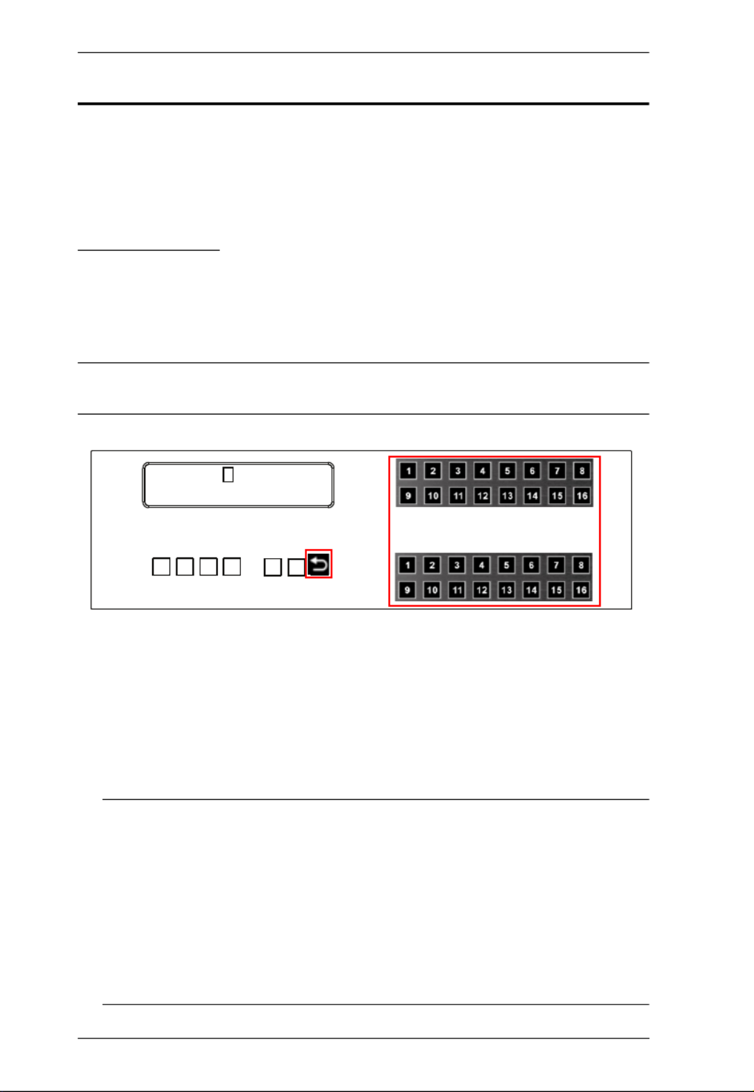
Input Port Selection
Use the Input Port pushbuttons to select the Input port you want to configure.
To select which input source displays on each output port, do the following:
1. Press an Input port pushbutton. The Output port LED(s) tied to the said
Input port light up. In the example below, pressing Input port 1 shows it is
tied to Output ports 1 and 2.
2. To disconnect an Output port from an Input port, press the corresponding
Output port pushbutton.
In the example below, Output port 2 has been disconnected from Input port
1.
INPUT
OUTPUT
1 2 5 5* 1 1 3 4
1 2 3 4 5 6 7 8
INPUT
OUTPUT
1 2 5 5 1 1 3 4
9 10 11 12 13 14 15 16
V + A
P1

Chapter 3. Front Panel Operation
45
3. To switch to another Input port, press any Input port pushbutton. The
Output port LED(s) tied to the said Input port light up.
In the example below, pressing Input port 2 shows it is tied to Output ports
3 4 and .
4. To connect Output port 2 to Input port 2 in the example above, press the
Output port 2 pushbutton. The Output port 2 LED will also light up. This
indicates that Input port 2 is now connected to Output ports 2 3, and 4.
Once the signal from the selected Input port is successfully tied to the
Output port, the LEDs turn off and the LCD information is updated.
Note: 1. Pressing an Input port a second time deselects it.
2. Input ports that are not configured or tied to any output port do not
appear in the LCD screen.
3. Pressing the Cancel pushbutton once stops the Input Port Selection
operation and the LCD displays the active setting. Pressing the
Cancel pushbutton again turns all LEDs off.
4. After 10 seconds of inactivity, all the LEDs turn off.

Modular Matrix Solution User Manual
46
Output Port Selection
Use the Output Port pushbuttons to select the Output port you want to
configure.
To select which output display corresponds to each input source, do the
following:
1. Press any Output port pushbutton (1-16). The selected Output port LED
lights steady.
In the example below, Output port 1 pushbutton has been pressed.
Available Input ports light up. Because no Input LEDs are on, no ports
have already been assigned to Output port 1.
2. If an Output port pushbutton is pressed a second time, it is deselected and
the LED turns off.
3. To connect the selected Output port(s) to an Input port, press the Input port
pushbutton to which you want the Output port(s) tied. The newly selected
Input port LED light up, and the LCD information is updated.
In the example below, pressing Input port 2 ties it to Output ports 2 3, and
4.
INPUT
OUTPUT
1 2 5 5* 1 1 3 4
1 2 3 4 5 6 7 8
INPUT
OUTPUT
1 2 5 5 1 1 3 4
9 10 11 12 13 14 15 16
V + A
P1

Chapter 3. Front Panel Operation
47
4. To switch Output ports 2, 3 and 4 to another Input port (and disconnect it
from Input port 2), press another Input port pushbutton to which you want
them tied.
In the example below, Input port 3 has been pressed and is now connected
to Output ports 2 3, and 4.
Note:
To cancel an output selection, press the pushbutton again.
Pressing the Cancel pushbutton once stops the Output Port Selection
operation, and the LCD displays the active setting. Pressing the Cancel
pushbutton again turns all LEDs off.
After 10 seconds of inactivity, all the LEDs turn off.

Modular Matrix Solution User Manual
48
Profile Pushbutton
From the Main screen; pressing the PROFILE pushbutton switches between
the connection profiles added to the Profile Selection list (see Setting the
Standby Mode, page 69). If a connection profile is in use, it is shown from the
Main screen on the lower right corner of the LCD display.
Use the front panel number pushbuttons to select a profile:
Input ports 1–16 correspond to Profile P1 to P16
Output ports 1–16 correspond to Profile P17 to P32
Note: If a Profile is available for selection, its corresponding Input/Output
port LED lights.
The selected pushbutton lights steady, and the VM1600A immediately
applies the port connections configured in the Profile. The selected Profile
is shown as P1-P32 in the LCD’s lower right corner.
Up Down and buttons correspond to the previous or next profile in the
Profile List, which can be edited via the GUI.
If there are no profiles configured, an error message “No Profile List
defined. Profile List can be edited via the Web GUI.” is displayed.
The Profile List and connections can be edited from the Profile List page
of the Browser GUI. See Setting the Standby Mode, page 69.
Press the Cancel pushbutton to turn off the Profile LED.
Pressing the Profile pushbutton for longer than 3 seconds displays the
Save to a Profile page (see Save to a Profile, page 64).
Note: To save a configuration to a profile using the Front Panel pushbuttons,
follow the steps in Save to a Profile, page 64.
INPUT
OUTPUT
1 2 5 5* 1 1 3 4
1 2 3 4 5 6 7 8
INPUT
OUTPUT
1 2 5 5 1 1 3 4
9 10 11 12 13 14 15 16
V + A
P1

Modular Matrix Solution User Manual
50
LCD Main Screen
The Main Screen shows the Input–Output port pairs, with the Output ports
shown in sequential order (1–16) at the bottom half.
The front panel pushbutton label (1–16) corresponds to the Input ports
and Output ports on the unit’s rear panel.
Use the Menu pushbutton to go to the Menu page.
Use the Profile pushbutton to switch between profile connections (see
Setting the Standby Mode, page 69).
INPUT
OUTPUT
1 2 5 5* 1 1 3 4
1 2 3 4 5 6 7 8
INPUT
OUTPUT
1 2 5 5 1 1 3 4
9 10 11 12 13 14 15 16
V + A
P1

Chapter 3. Front Panel Operation
51
IP Setting
To view the VM1600A’s IP settings, press the Menu pushbutton (lights). This
takes you to the Menu page, shown below:
1. From the Menu page:
Press 1 to go to the IP Setting page.
Press 2 to go to the Serial Port Setting page.
Press 3 to go to the Operation Mode page.
Press 4 to go to the Security Mode page.
Press Down button to go to the next page.
Press Menu to return to the Menu Screen.
Press Cancel to return to the Main Screen.
2. After pressing 1 , the IP address, Subnet Mask and Gateway information
are shown:
The default IP address is 192.168.0.60.
The default Subnet Mask is 255.255.255.0.
The default Gateway is 192.168.0.1.
3. Press Cancel to return to the previous step without change.
1: IP Seng
2: Serial Port Seng
3: Operaon Mode
4: Security Mode
IP Address: 192.168.0.60
Subnet Mask: 255.255.255.0
Gateway: 192.168.0.1
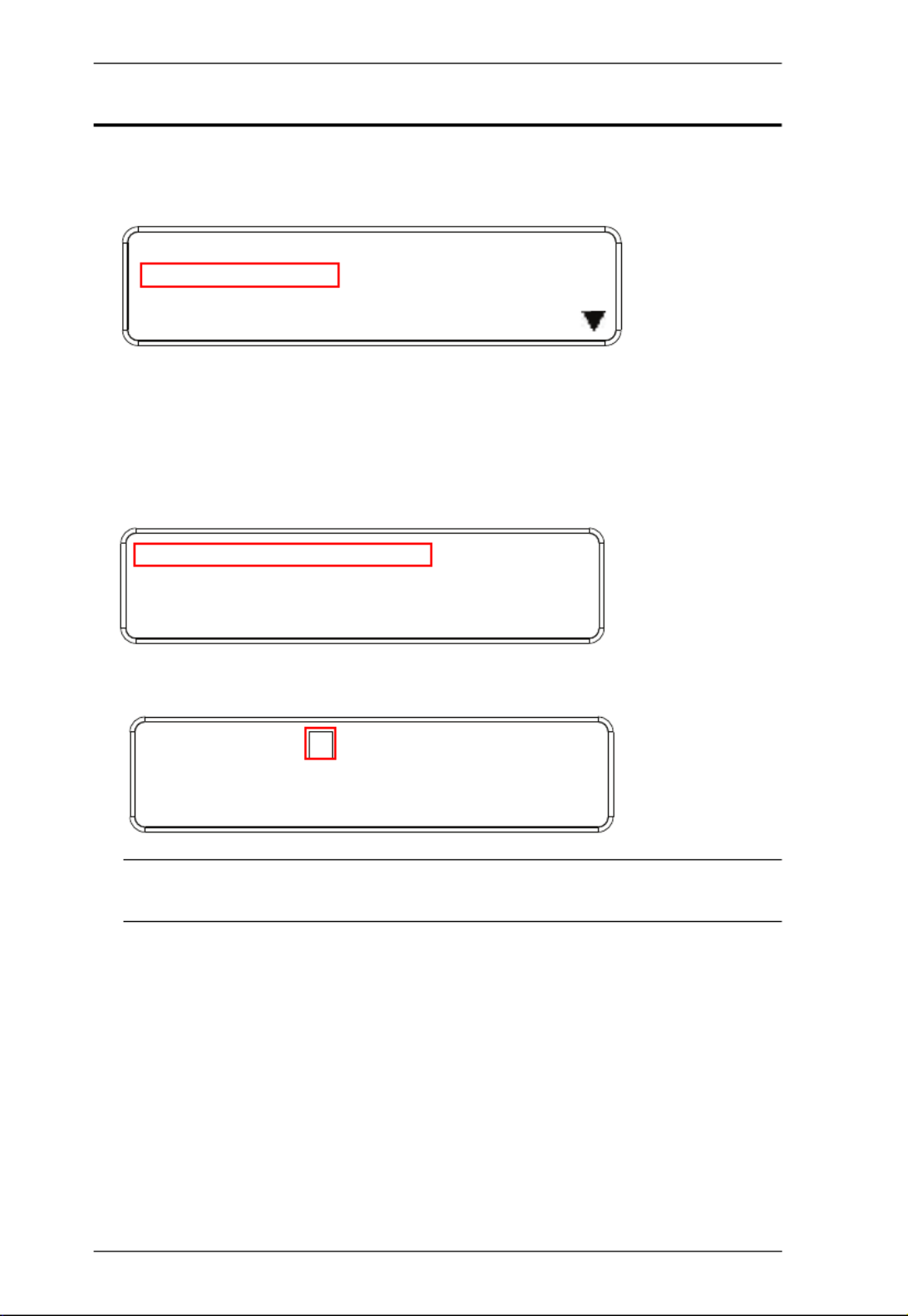
Modular Matrix Solution User Manual
52
Serial Port Setting
To configure the VM1600A’s serial port settings, select Serial Port Setting
from the Menu page.
Serial Port Address Setting
To set the VM1600A’s serial port address, do the following:
1. Select Serial Port Address Setting from the Serial Port Setting submenu
by pressing 1:
2. Press pushbuttons 1–16 to make your selection.
Note: The default serial port address is 1. This address is used for RS422/
485 commands to control multiple VM1600A’s.
3. Press Menu to return to the Menu page.
4. Press Cancel to return to the previous step without saving.
1: IP Seng
2: Serial Port Seng
3: Operaon Mode
4: Security Mode
1: Serial Port Address Seng : 1
2: Baud Rate Seng: 19200
3: Serial Port Mode: RS232
Serial Port Address : 1

Chapter 3. Front Panel Operation
53
Baud Rate
1. Select Baud Rate Setting from the Serial Port Setting submenu by
pressing 2:
2. Press pushbuttons 1–4 to make your selection.
Baud Rate options are:
1: 9600
2: 19200
3: 38400
4: 115200
Note: The default baud rate is 19200.
3. Press Menu to return to the Menu page.
4. Press Cancel to return to the previous step without saving.
Serial Port Mode
1. Select Serial Port Mode from the Serial Port Setting submenu by pressing
3:
1: Serial Port Address Seng : 1
2: Baud Rate Seng: 19200
3: Serial Port Mode: RS232
1: 9600
2: 19200 (In use)
3: 38400
4: 115200
1: Serial Port Address Seng : 1
2: Baud Rate Seng: 19200
3: Serial Port Mode: RS232

Modular Matrix Solution User Manual
54
2. Press pushbuttons 1–2 to make your selection.
Serial Port options are:
1: RS-232
2: RS-422 / RS-485
Note: The default serial port mode is RS-232.
3. Press Menu to return to the Menu page.
4. Press Cancel to return to the previous step without saving.
1: RS232 (In use)
2: RS422/RS485

Chapter 3. Front Panel Operation
55
Operation Mode
The EDID, CEC, OSD and Output Status features are adjusted from the
Operation Mode menu.
EDID (extended display identification data) is used to apply a preset video
configuration (EDID Mode), which utilizes the best resolution across
different monitors.
Consumer Electronics Control (CEC) allows interconnected HDMI
devices to communicate and respond to one remote control.
The OSD, when enabled for a port, displays real-time port switching
information on the screen.
The Output Status shows whether the video/audio of an Output port is
turned on or off.
EDID
To adjust the EDID mode, do the following:
1. From the Operation page, press pushbutton 1 to access the EDID Mode
page:
2. Press pushbuttons 1-4 to make your selection.
1: EDID Mode: Default
2: CEC
3: OSD
4: Output Status
1: EDID Mode: Default
2: CEC
3: OSD
4: Output Status
1: Port 1
2: Default (In use)
3: Remix
4: Customized

Modular Matrix Solution User Manual
56
EDID Mode options are:
3. Press Menu to return to the Menu page.
4. Press Cancel to return to the previous step without change.
Note: The default EDID setting is Default.
EDID Option Description
1: Default ATEN’s default EDID data is passed to all video sources by
default when the system is powered on.
2: Port1 EDID data read from port 1 is passed to all video sources.
The system will enforce the Default EDID setting if port 1 is
not occupied.
3: Remix This mode reads the EDID data from all connected displays
and generates the optimum EDID for all video sources. The
system will not re-generate a new EDID when a new device
is plugged in, unless triggered by a pushbutton or command.
4: Customized This mode features an EDID Wizard that allows user-
defined EDID configurations for optimum output.
See Customized Mode, page 108.

Chapter 3. Front Panel Operation
57
CEC
To configure the CEC settings, do the following:
1. From the Operation page, press pushbutton 2 to access the CEC page:
2. Press pushbuttons 1–16 to enable (ON) or disable (NA) the CEC feature
for the output port. If the port does not support CEC, an NA is shown.
Note: The default CEC setting is Off.
3. Press Menu to return to the Menu page.
4. Press Cancel to return to the previous step without saving.
1: EDID Mode: Default
2: CEC
3: OSD
4: Output Status
OUTPUT
1 2 3 4 5 6 7 8
NA NA NA NA ON NA ON NA
OUTPUT
9 10 11 12 13 14 15 16
ON ON ON ON NA NA NA NA
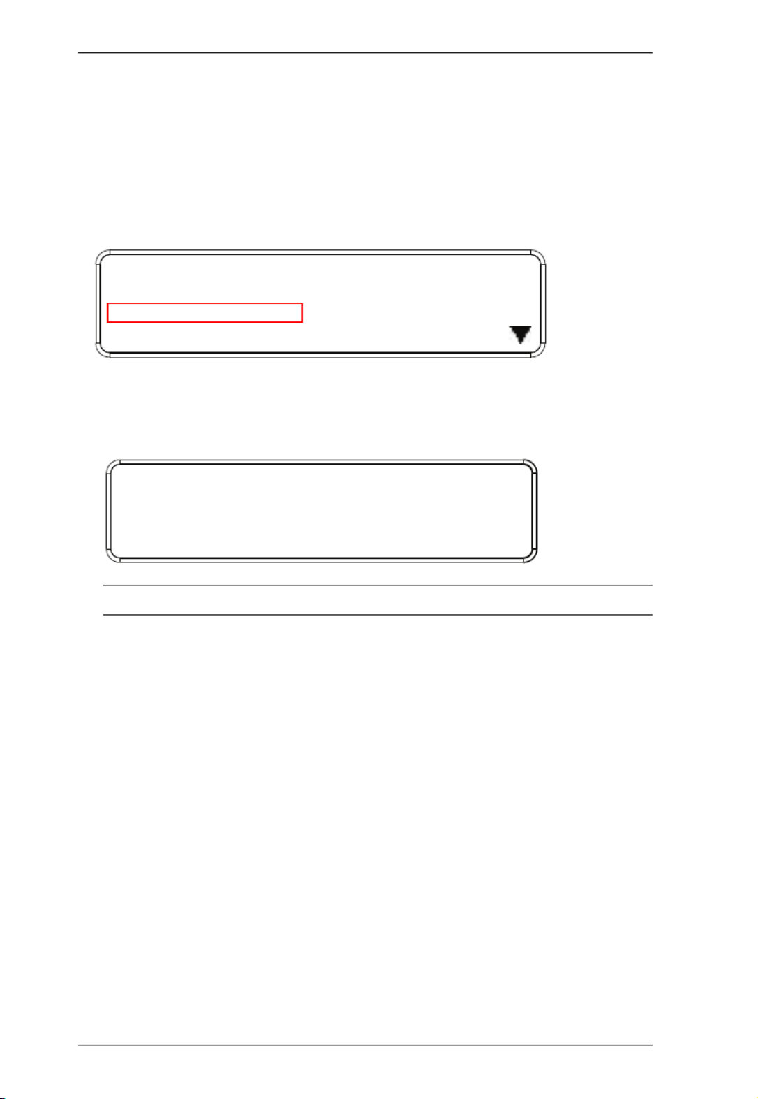
Modular Matrix Solution User Manual
58
OSD
The On-Screen Display or OSD feature enables real-time text updates to
appear on the display device’s screen for any configuration changes made to
the Output port via the VM1600A’s front panel, remote control or Web GUI.
To configure the OSD setting for each output port, do the following:
1. From the Operation page, press pushbutton 3 to access the OSD page:
2. Press pushbuttons 1–16 to enable (ON) or disable (NA) the OSD feature
for the port.
Note: The default OSD setting is Off.
3. Press Menu to return to the Menu page.
4. Press Cancel to return to the previous step without saving.
1: EDID Mode: Default
2: CEC
3: OSD
4: Output Status
OUTPUT
1 2 3 4 5 6 7 8
NA NA NA NA ON NA ON NA
OUTPUT
9 10 11 12 13 14 15 16
ON ON ON ON NA NA NA NA
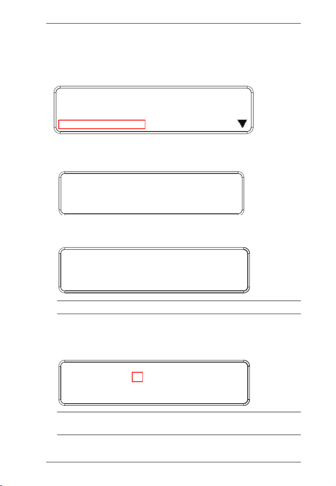
Chapter 3. Front Panel Operation
59
Output Status
To configure the Output Status settings for each output port, do the following:
1. From the Operation Mode screen, press pushbutton 4 to access the Output
Status page:
2. Press pushbuttons 1–3 to select whether you want to configure the video,
stereo audio, or output resolution for output ports.
3. If configuring the output port status for video, press pushbuttons 1–16 to
enable (ON) or disable (NA) the video channel:
Note: The default Output Status setting is On.
4. If configuring the output port status for stereo audio, press pushbuttons
1–16 to select the output port. Adjust the audio volume for the port by
pressing the Up or Down pushbutton:
Note: The audio volume range from 0 (mute) and 1 (~27dB) to 10 (0dB).
The default audio volume is 10.
1: EDID Mode: Default
2: CEC
3: OSD
4: Output Status
1: Video
2: Stereo Audio
3: Output Resoluon
OUTPUT
1 2 3 4 5 6 7 8
NA NA NA NA ON NA ON NA
OUTPUT
9 10 11 12 13 14 15 16
ON ON ON ON NA NA NA NA
OUTPUT
1 2 3 4 5 6 7 8
0 10 [1] 4 8 8 8 8
OUTPUT
9 10 11 12 13 14 15 16
0 10 10 4 8 8 8 8
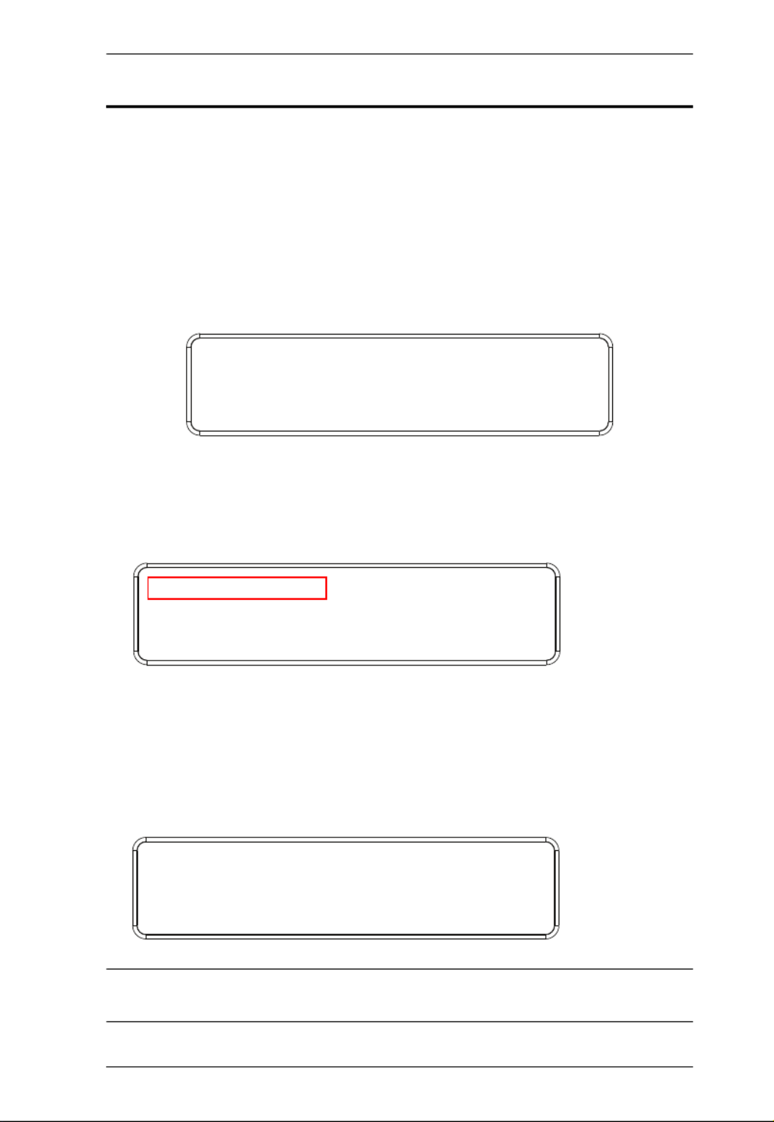
Chapter 3. Front Panel Operation
61
Security Mode
The Security Mode page allows you to configure the VM1600A’s password-
related settings; the Password page sets the VM1600A to require a password
for local operation after the LCD display times out (default time out: 5 minutes)
or is powered off/on. The Change Password option allows you to set a new
password for the VM1600A.
To configure the VM1600A’s password settings from the Main Screen, use the
Menu pushbutton to access the Menu page, then press pushbutton 4 to access
the Security Mode page.
Mode
1. To set the VM1600A so that it requires a password for local operation,
press pushbutton 1 in the Security Mode page.
2. To disable security settings, press pushbutton 1.
3. To require a password after the LCD display times out or is powered off/
on, press pushbutton 2.
4. To enable a lock screen, press pushbutton 3. When Lock Screen is enabled,
pressing any pushbutton from the home screen will trigger the following
message: Please press “Menu” to start.
Note: By default the password requirement is disabled. If the password is
enabled, the LCD display’s default time-out is 5 minutes.
1: Mode
2: Change Password
1: Mode
2: Change Password
1: None
2: Password Enable
3: Lock Screen

Modular Matrix Solution User Manual
62
5. Press Menu to return to the Menu page.
6. Press Cancel to return to the previous step without saving.
Change Password
1. To change the password: from Security Mode, press pushbutton 2.
2. In the Old Password field, the cursor flashes at the first digit. Enter the old
password (see LCD Password, page 42). If the old password is entered
correctly, you can proceed to the next step. The default password is: 1234.
Note: If you enter an incorrect password, the cursor goes back to the first digit
and reverts to flashing. The Incorrect Password message clears as soon
as a new digit is entered.
3. In the New Password field, the cursor flashes at the first digit. Enter the
new password using the front panel number pushbuttons (1111–9999).
1: Mode
2: Change Password
Old Password : * * * *
Old Password : * * * *
New Password: * * * *

Chapter 3. Front Panel Operation
63
4. Re-enter the new password in the following screen. The new password is
applied by the VM1600A immediately.
If the password you entered does not match the one entered in the previous
screen, an error message appears. Enter the new password correctly.
5. Press Menu to return to the Menu page.
6. Press Cancel to return to the previous step without saving.
Old Password : * * * *
New Password: * * * *
Re-enter New Password: * * * *
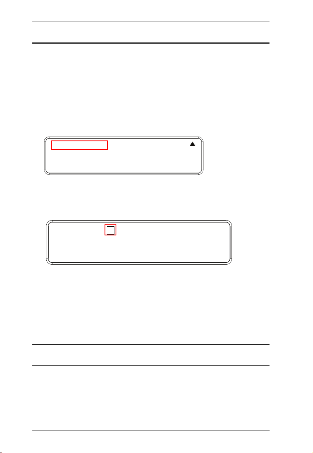
Modular Matrix Solution User Manual
64
Save to a Profile
The VM1600A allows you to store up to 32 (P1–P32) different connection
profiles that can be saved and recalled later. When profiles are saved, they are
saved according to the current connection configuration on the Main Screen.
When you load a profile, the change is immediate and the profile number is
shown in the lower right corner of the LCD display. To save profiles, from the
Main Screen do the following:
1. Use the Menu pushbutton to access the Menu page, and Down to navigate
to the next page. Press pushbutton 1 to open the Save to a Profile page.
2. To save the active connection configuration as a profile use the front panel
number pushbuttons to select a profile into which you want to save the
configuration.
Input ports 1–16 correspond to Profile P1 to P16
Output ports 1–16 correspond to Profile P17 to P32
3. Press the Profile pushbutton to store the connection configuration – the
LCD shows a Profile Saved message.
4. Press Menu to return to the Menu page.
5. Press Cancel to return to the previous step without saving.
Note: You can also access the Save to a Profile page by pressing the Profile
pushbutton for longer than 3 seconds.
1: Save to a Profile
2: Play/Stop the Profile Schedule
3: Turn Video Wall Off
Save to a Profile: 1
(In1->16 = P1->16; Out1->16 = P17->P32.
Press Profile to save.)

Chapter 3. Front Panel Operation
65
Play/Stop the Profile Schedule
Inputting port pushbutton 2 will Play or Stop the active Profile Schedule.
Turn Video Wall Off
If a video wall is currently playing, a submenu will appear.
Selecting Turn Video Wall Off will return port assignments to their default
(i.e. disassemble the video wall).
1: Save to a Profile
2: Play/Stop the Profile Schedule
3: Turn Video Wall Off
1: Save to a Profile
2: Play/Stop the Profile Schedule
3: Turn Video Wall Off

Modular Matrix Solution User Manual
66
This Page Intentionally Left Blank

67
Chapter 4
Browser Operation
Overview
The VM1600A can be configured over a standard TCP/IP connection via its
built-in Graphical User Interface (GUI). Because it can be accessed from
anywhere over a network or the Internet, operators can easily log in via web
browser. Security is ensured by password protection and user-configurable
time-out. The VM1600A supports three levels of remote users with various
privileges, and up to 16 users can log into the GUI at one time. For full details
see the sections that follow.
Logging In
To access the GUI, type the VM1600A’s IP address into the address bar of any
browser. If a Security Alert dialog box appears, accept the certificate – it can
be trusted. The login screen appears:
The default IP address is http://192.168.0.60
The default Username and Password are: administrator / password
Enter the username and password, then click Login.
Use the drop-down menu to select the GUI language
Note: 1. The username supports lower case letters only.
2. The same user can not be logged in simultaneously.

Modular Matrix Solution User Manual
68
Main Page
The main page opens to Profile List. Use Profile List to configure the input to
output connections by creating profiles, import or export profiles, or create a
profile schedule. The page is divided into three parts: the Menu Bar, Profile
List, and Profile Scheduling.

Modular Matrix Solution User Manual
86
Playing a Profile
1. Click the profile you wish to apply and then click Apply.
2. The profile is immediately applied and appears in the large Play window.

Chapter 4. Browser Operation
87
3. To adjust the played profile, click on the Play window. The following
controls appear.
Option Description
Show OSD Check Show OSD to show the current connection status via
OSD. When Show OSD is unchecked, the OSD will disappear.
Mute All Check Mute All to mute the audio for all ports.
Blank All Check Blank All to turn off the video to all displays.
Click this icon to show a source assignment for this profile.
On Sequence On Sequence appears when a profile schedule is playing.
Positioning Click Positioning to open a window that allows you to adjust
the image position on each display. For Video Wall profiles, you
can also set the Bezel Dimension, which is the frame thickness
between each display.
Change Input Click Change Input to change the input for single and grouped
outputs, as explained on the next page.
Click this icon to delete the profile.
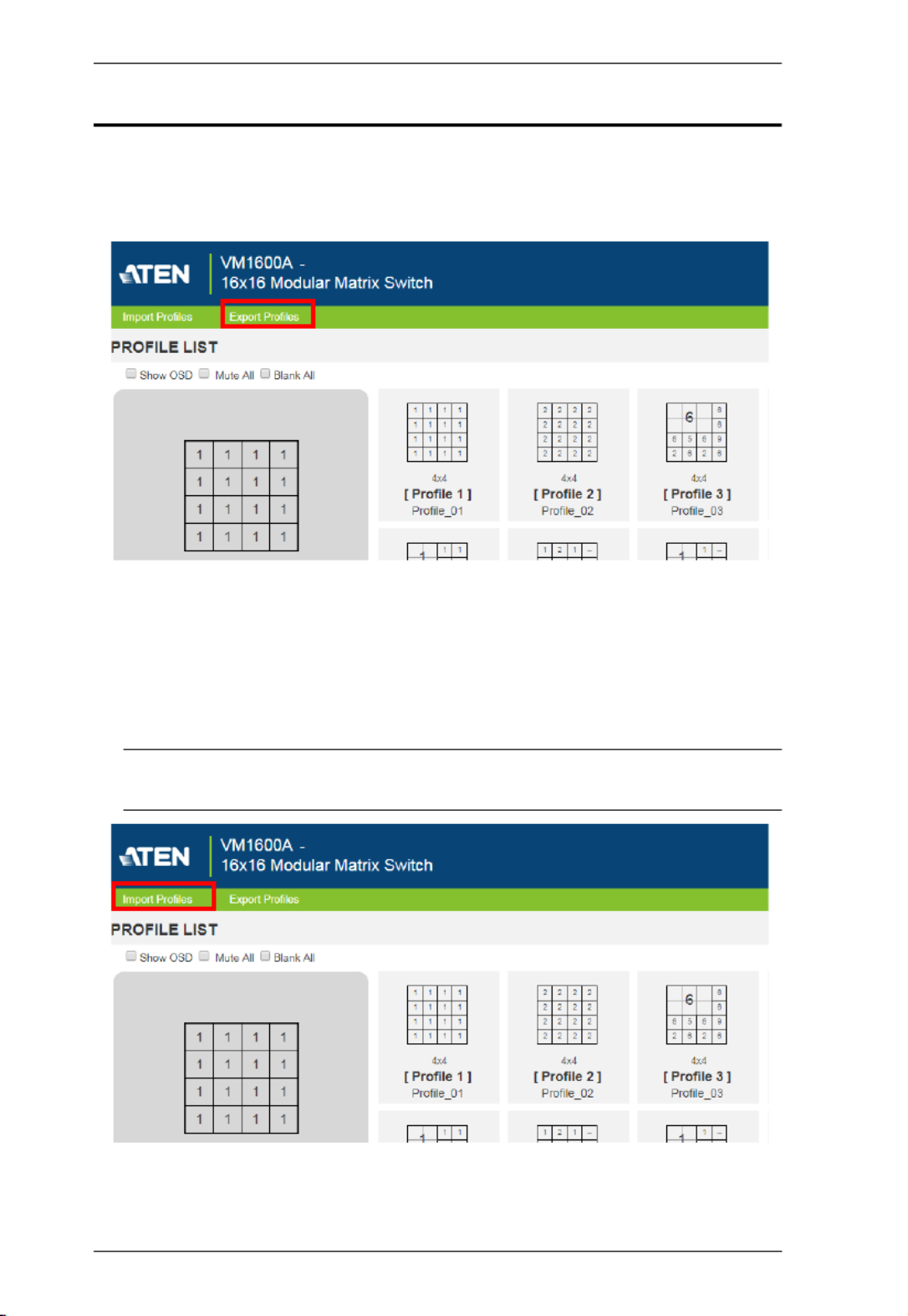
Modular Matrix Solution User Manual
88
Importing/Exporting a Profile
To export the VM1600A’s connection profiles, click Export Profiles. A
configuration file starts downloading.
To import connection profiles to the VM1600A, do the following:
1. Click Import Profiles.
2. Browse to the configuration file, select it and click Open.
Note: Importing a connection profile database will overwrite the current
profiles.
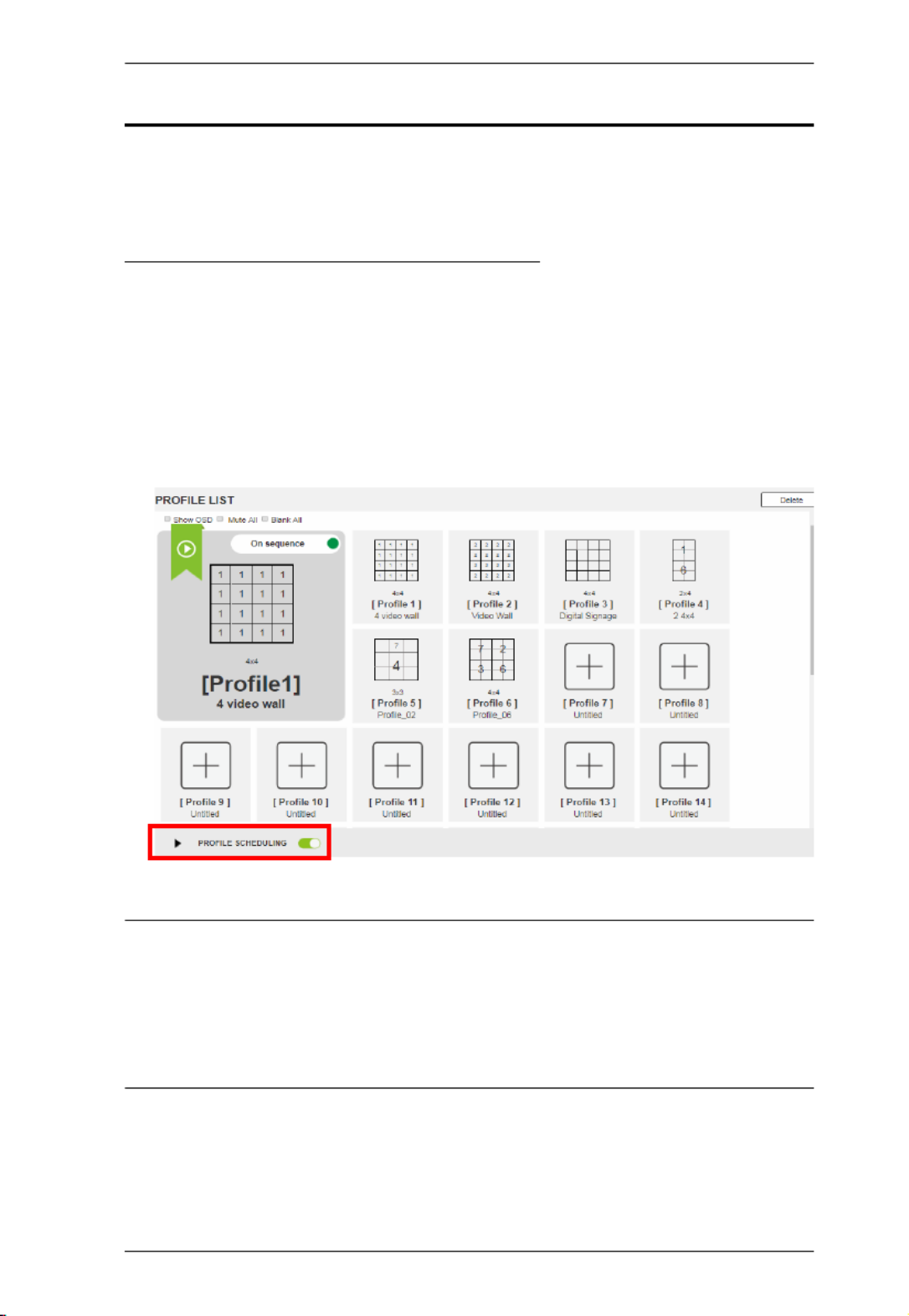
Chapter 4. Browser Operation
89
Profile Scheduling
You can create one or more profile playlists that play periodically on specified
time frames.
Enabling/Disabling Profile Schedule
To have the Matrix Switch play profile playlists, follow the steps below.
1. Go to the Profile List page.
2. Configure profile playlists. For details, see Adding Profile Playlists,
page 90.
3. From the Profile List page, click the PROFILE SCHEDULING toggle
button to enable (green) or disable (gray) profile schedules.
Note: For firmware prior to version 4.2.416, if profile scheduling is disabled
and re-enabled within the scheduled time frame of a playlist, the
VM1600A will resume playing the first profile in the playlist; for
VM1600A of firmware version 4.2.416 or later, the system will resume
playing the playlist according to schedule, and the profiles that were to
be played during the paused period will be skipped.
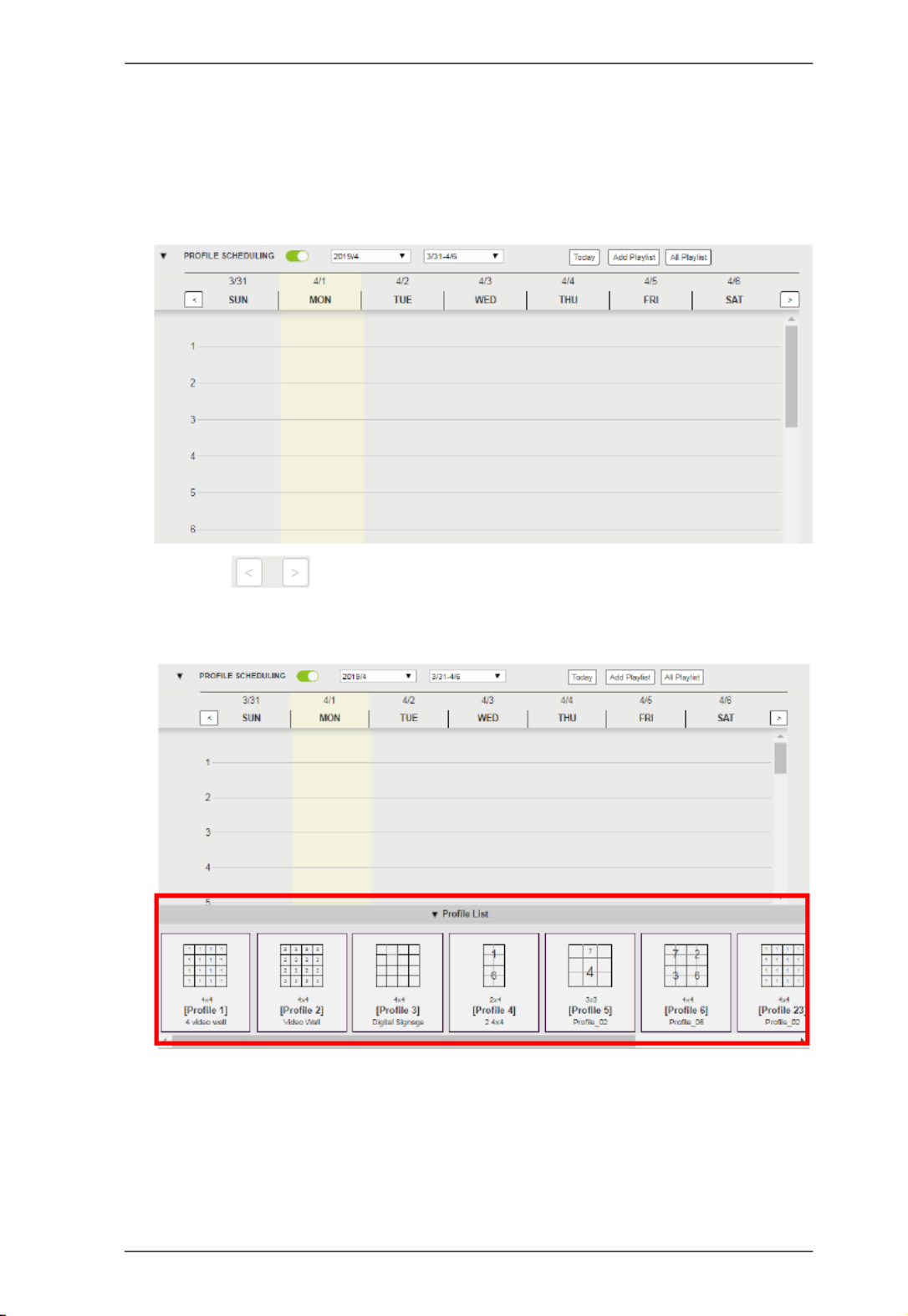
Chapter 4. Browser Operation
93
Adding a One-off Profile Playlist
To add a playlist that plays once, follow the steps below.
1. From the Profile List page, click PROFILE SCHEDULING. A profile
calendar appears.
2. Use the buttons to adjust the calendar to a time frame to which
you wish to add profiles.
3. Click Profile List at the bottom of the page. The Profile List appears.
4. From the Profile List, drag and drop profiles onto the desired time on the
calendar view. Optionally right-click the profile to copy, remove, or view
its settings.

Modular Matrix Solution User Manual
94
Editing, Removing, or Copying Profile Playlists
To edit, remove, or copy profile playlists:
1. Click the button from the Profile List page to open the All
Playlist window.
2. Move the cursor to a playlist you want to edit, copy, or remove.
3. Click one of the following buttons.
Control Description
Click to add a new profile playlist.
View / Edit
Click to edit or view the selected profile playlist.
Copy
Click to create a copy of the selected profile playlist.
Remove
Click to remove the selected profile playlist.
Modular Matrix Solution User Manual
96
The table below provides an overview of the available settings for each tab.
Tab Supported Functions Detailed Information
General
Configure the device name
Select the interface language
Monitor the VM1600A’s fan temperature
and configure the fan speed
Monitor the system’s power status
Configure the settings for serial
communications
For more information,
see General, page 98.
Port Settings
Configure the OSD and CEC port
settings
Configure the HDCP key for input and
output ports
Configure the Seamless Switch™
settings
Name the input and output ports
Select EDID modes
For more information,
see Port Settings,
page 100.
Status
View statuses of the input/output boards
installed to the VM1600A and enable/
disable FrameSynce and Long Reach
mode for the board.
View system information such as
network settings, firmware version, and
the settings for audio/video assignment,
volume, CEC, audio mode settings, and
more.
For more information,
see YCBCR 4:2:0 Video
Data Block, page 116.
Channel
Configure the IR routes for the input/
output boards.
Configure the RS-232 serial
communication routes for the input/
output boards.
Note: The IR/RS-232 Channel settings are
only supported by VM7514/VM7584 Input
Board or VM8514/VM8584 Output Board.
For more information,
see Channel, page 120.

Chapter 4. Browser Operation
97
Maintenance
Upgrade the firmware for the installed
input and output boards
Back up or restore the VM1600A’s
configuration
Add, edit, or remove user accounts
Configure the system network settings
See Maintenance,
page 122.
Tab Supported Functions Detailed Information

Chapter 4. Browser Operation
99
Power Status
This section displays the status and percentage used of the Primary and
Redundant Power units.
Serial Settings
Serial Port Mode: Defines the serial communications mode for the
VM1600A.
RS-232 Configuration Mode: Allows the user to configure
VM1600A’s system via RS-232 serial commands.
RS-232 Control Mode: Allows the user to control remote devices that
are connected to VM1600A through its RS-232 channels. To enable
this feature, select the RS232 Control Mode and configure the input to
output settings. For details, see Channel, page 120.
Note: To enable this feature, make sure to also configure the RS-232
channeling. For details, see Channel, page 120.
RS-422/RS-485: If you are using RS422/RS485, define the Serial Port
Address using the drop-down list.
Serial Port Address: Defines the serial port address.
Baud rate: Defines the baud rate for the serial port.
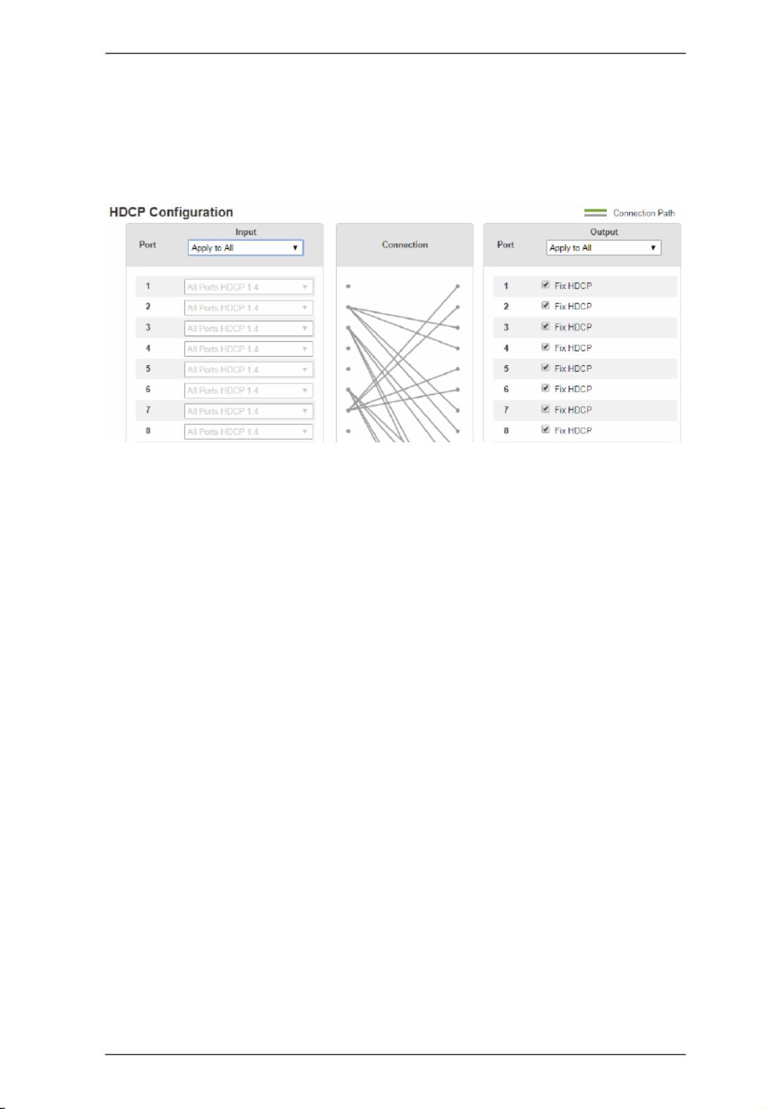
Chapter 4. Browser Operation
101
HDCP
The HDCP page lets users view and set HDCP key settings between input and
output ports for digital copy protection and to ensure Seamless Switch™ is
used between different devices. This is an Administrator and Advanced User
only function.
Connection
Here users can find a visual display of connection paths between inputs and
outputs. When selecting an input, its path is displayed in green.
Output
Here users can define whether or not HDCP settings are fixed, either by
individual port or by applying one setting to all ports. By prearranging and
fixing keys, this setting ensures that Seamless Switch™ is possible even when
switching between HDCP and non-HDCP enabled devices.
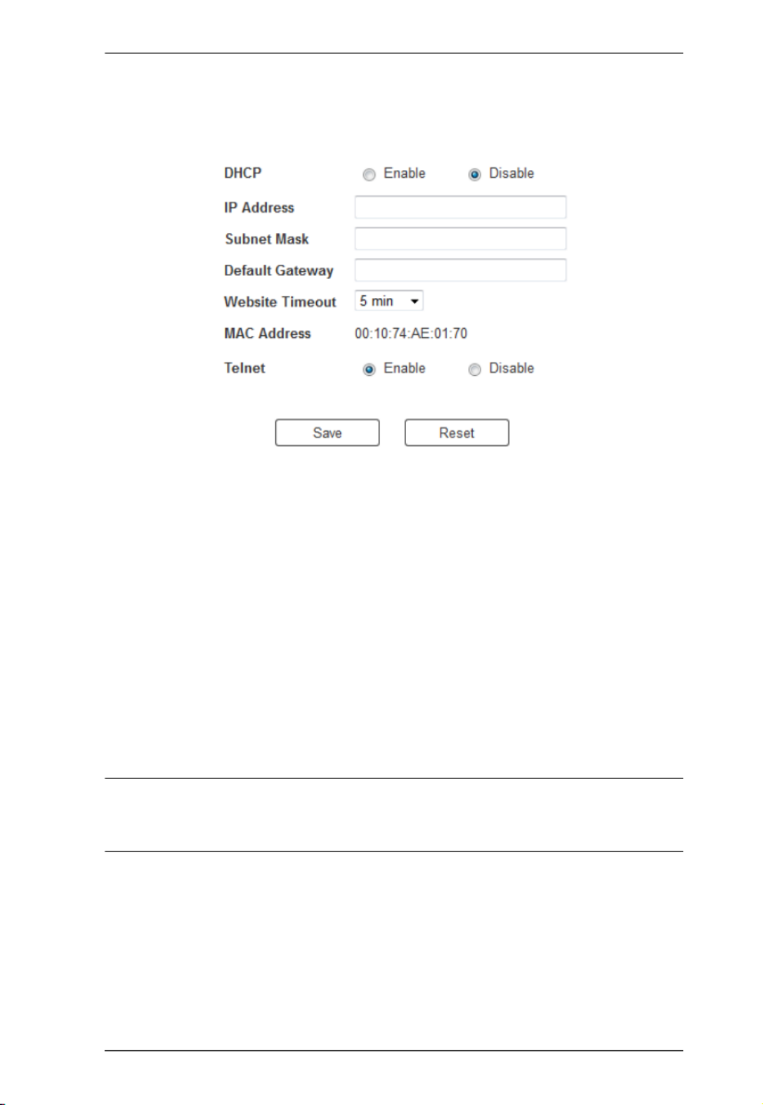
Chapter 4. Browser Operation
127
Network
The Network page lets you configure the VM1600A’s IP settings for
connecting to it via the web GUI, and enable/disable Telnet.
Enable DHCP to allow the DHCP server to assign an IP address to the
VM1600A. Select Disable to enter your own static IP address settings for the
device.
Click Reset to use the following default values:
IP Address – 192.168.0.60
Subnet Mask – 255.255.255.0
Default Gateway – 192.168.0.1
Website Timeout* – N/A, 5, 10, 30, 60 minutes
Telnet Configuration enabled (checked)
Enter the values, then click Save. Changes may take a few seconds and after
refreshing the page automatically redirects you to the IP address specified.
* This option controls how long an inactive web connection stays logged
into the VM1600A. Any changes will take effect immediately. The
default setting is 5 minutes.

Modular Matrix Solution User Manual
136
Commands
After connecting to the VM1600A via Telnet or RS-232, you can operate the
system using the following commands.
Switch Port Command
The formula for Switch commands is as follows:
Switch Command + Input + Num1 + Output + Num2 + Address +
Num3 + Stream + Control [Enter]
1. For example, to switch input port 02 to output port 05, type the following:
sw i02 o05 [Enter]
2. To switch output port 04 to the next port, input the following:
sw o04 + [Enter]
3. To turn off video output on port 03, type the following:
sw o03 off [Enter]
4. To turn off video output on port 03 on device 02, type the following:
sw o03 a02 off [Enter]
The following tables show the possible values for the Switch Port command
Command Description
sw Switch command
Input Description
i Input port command
Num1 Description
xx Input port
xx: 01~16
* All input ports
Output Description
o Output port command
Num2 Description
yy Output port
yy: 01~16
Specyfikacje produktu
| Marka: | ATen |
| Kategoria: | przełącznik |
| Model: | VM3250 |
Potrzebujesz pomocy?
Jeśli potrzebujesz pomocy z ATen VM3250, zadaj pytanie poniżej, a inni użytkownicy Ci odpowiedzą
Instrukcje przełącznik ATen

28 Grudnia 2024
23 Września 2024
23 Września 2024
22 Września 2024
22 Września 2024
22 Września 2024
22 Września 2024
22 Września 2024
22 Września 2024
22 Września 2024
Instrukcje przełącznik
- przełącznik Yamaha
- przełącznik Ikea
- przełącznik Tenda
- przełącznik Worx
- przełącznik Huawei
- przełącznik TP-Link
- przełącznik Philips
- przełącznik Plantronics
- przełącznik SilverCrest
- przełącznik Bosch
- przełącznik Hikvision
- przełącznik IPGARD
- przełącznik Toolcraft
- przełącznik Panasonic
- przełącznik StarTech.com
- przełącznik Theben
- przełącznik Crestron
- przełącznik Behringer
- przełącznik Asus
- przełącznik Nedis
- przełącznik Nexa
- przełącznik Boss
- przełącznik TRENDnet
- przełącznik Tesla
- przełącznik D-Link
- przełącznik Metra
- przełącznik APC
- przełącznik Alcatel
- przełącznik Eberle
- przełącznik HP
- przełącznik Honeywell
- przełącznik Manhattan
- przełącznik Tripp Lite
- przełącznik Mikrotik
- przełącznik Mercury
- przełącznik Shimano
- przełącznik Audac
- przełącznik Cisco
- przełącznik ORNO
- przełącznik Alpine
- przełącznik Chamberlain
- przełącznik Paladin
- przełącznik Lindy
- przełącznik ZyXEL
- przełącznik LogiLink
- przełącznik IFM
- przełącznik Linksys
- przełącznik Digitus
- przełącznik Vimar
- przełącznik Dahua Technology
- przełącznik Schneider
- przełącznik Renkforce
- przełącznik BaseTech
- przełącznik Perel
- przełącznik Trotec
- przełącznik Adder
- przełącznik Ansmann
- przełącznik Netgear
- przełącznik Velleman
- przełącznik Homematic IP
- przełącznik DataVideo
- przełącznik One For All
- przełącznik Totolink
- przełącznik Intertechno
- przełącznik Black Box
- przełącznik Victron Energy
- przełącznik Delta Dore
- przełącznik Pyle
- przełącznik Lancom
- przełącznik Adviti
- przełącznik Iogear
- przełącznik Intellinet
- przełącznik Setti+
- przełącznik Jabra
- przełącznik Vivotek
- przełącznik PreSonus
- przełącznik Mercusys
- przełącznik Shelly
- przełącznik Edimax
- przełącznik AirLive
- przełącznik EnGenius
- przełącznik SPC
- przełącznik Planet
- przełącznik Brilliant
- przełącznik Blustream
- przełącznik LevelOne
- przełącznik Vivolink
- przełącznik Suevia
- przełącznik Abus
- przełącznik Omnitronic
- przełącznik Elro
- przełącznik Hama
- przełącznik Marmitek
- przełącznik Ubiquiti Networks
- przełącznik Smart-AVI
- przełącznik Goobay
- przełącznik Kaiser
- przełącznik Equip
- przełącznik Kemo
- przełącznik Juniper
- przełącznik Cudy
- przełącznik QNAP
- przełącznik Micro Connect
- przełącznik Hager
- przełącznik Extech
- przełącznik Elation
- przełącznik Rex
- przełącznik Emerson
- przełącznik Ernitec
- przełącznik Vemer
- przełącznik CyberPower
- przełącznik Electro Harmonix
- przełącznik Atlona
- przełącznik Elektrobock
- przełącznik Fibaro
- przełącznik Gefen
- przełącznik SEADA
- przełącznik Vivanco
- przełącznik Grandstream
- przełącznik Powerfix
- przełącznik Alecto
- przełącznik Vacmaster
- przełącznik Kathrein
- przełącznik JUNG
- przełącznik Eaton
- przełącznik Monacor
- przełącznik H-Tronic
- przełącznik EVE
- przełącznik Smartwares
- przełącznik Sygonix
- przełącznik Cotech
- przełącznik Dormakaba
- przełącznik Alfatron
- przełącznik Clas Ohlson
- przełącznik Kopp
- przełącznik Speaka
- przełącznik Belkin
- przełącznik Generac
- przełącznik Kramer
- przełącznik KanexPro
- przełącznik BZBGear
- przełącznik RGBlink
- przełącznik Raritan
- przełącznik AMX
- przełącznik Sonance
- przełącznik Profile
- przełącznik Intermatic
- przełącznik Flamingo
- przełącznik Brennenstuhl
- przełącznik Eminent
- przełącznik KlikaanKlikuit
- przełącznik Ei Electronics
- przełącznik Sylvania
- przełącznik Tork
- przełącznik Techly
- przełącznik Matrox
- przełącznik Steren
- przełącznik AV:link
- przełącznik Buffalo
- przełącznik Audiovox
- przełącznik Merten
- przełącznik Chacon
- przełącznik Konig
- przełącznik UPM
- przełącznik Finder
- przełącznik Fantini Cosmi
- przełącznik DoorBird
- przełącznik Grasslin
- przełącznik Gira
- przełącznik WHALE
- przełącznik PAC
- przełącznik Wentronic
- przełącznik Wago
- przełącznik Lanberg
- przełącznik Monoprice
- przełącznik Nous
- przełącznik Tiptel
- przełącznik OSD Audio
- przełącznik Unify
- przełącznik Berker
- przełącznik Aeon Labs
- przełącznik Provision ISR
- przełącznik CSL
- przełącznik PCE
- przełącznik SIIG
- przełącznik Advantech
- przełącznik Merlin Gerin
- przełącznik Intelix
- przełącznik Extron
- przełącznik Avocent
- przełącznik Heitronic
- przełącznik Ebode
- przełącznik Robbe
- przełącznik ICasa
- przełącznik B-tech
- przełącznik GAO
- przełącznik Legrand
- przełącznik Kraus & Naimer
- przełącznik Noble
- przełącznik Ecler
- przełącznik Inverto
- przełącznik Triax
- przełącznik Rule
- przełącznik CYP
- przełącznik Phoenix Contact
- przełącznik Seuthe
- przełącznik Maclean Energy
- przełącznik SmartAVI
- przełącznik Leviton
- przełącznik DEHN
- przełącznik SEC24
- przełącznik Cooking Performance Group
- przełącznik Flic
- przełącznik HELGI
- przełącznik IB Connect
- przełącznik Liberty
- przełącznik PureTools
- przełącznik SunBriteTV
- przełącznik Hamlet
- przełącznik Noark
- przełącznik Cambium Networks
- przełącznik 2USB
- przełącznik Roline
- przełącznik KVM-TEC
- przełącznik STI
- przełącznik Epiphan
- przełącznik Ebara
- przełącznik Mach Power
- przełącznik Axing
- przełącznik ConnectPro
- przełącznik Atlantis Land
- przełącznik GEV
- przełącznik Pizzato Elettrica
- przełącznik Baco
- przełącznik Doepke
- przełącznik Comet
- przełącznik PureLink
- przełącznik INOGENI
- przełącznik Luxul
Najnowsze instrukcje dla przełącznik
9 Kwietnia 2025
9 Kwietnia 2025
7 Kwietnia 2025
5 Kwietnia 2025
4 Kwietnia 2025
4 Kwietnia 2025
4 Kwietnia 2025
3 Kwietnia 2025
3 Kwietnia 2025
2 Kwietnia 2025