Instrukcja obsługi Asrock Rack D1622D4I
Przeczytaj poniżej 📖 instrukcję obsługi w języku polskim dla Asrock Rack D1622D4I (44 stron) w kategorii serwer. Ta instrukcja była pomocna dla 7 osób i została oceniona przez 2 użytkowników na średnio 4.5 gwiazdek
Strona 1/44


Version 1.0
Published January 2020
Copyright©2020 ASRock Rack Inc. All rights reserved.
Copyright Notice:
No part of this documentation may be reproduced, transcribed, transmitted, or
translated in any language, in any form or by any means, except duplication of
documentation by the purchaser for backup purpose, without written consent of
ASRock Rack Inc.
Products and corporate names appearing in this documentation may or may not
be registered trademarks or copyrights of their respective companies, and are used
only for identication or explanation and to the owners’ benet, without intent to
infringe.
Disclaimer:
Specications and information contained in this documentation are furnished
for informational use only and subject to change without notice, and should not
be constructed as a commitment by ASRock Rack. ASRock Rack assumes no
responsibility for any errors or omissions that may appear in this documentation.
With respect to the contents of this documentation, ASRock Rack does not provide
warranty of any kind, either expressed or implied, including but not limited to
the implied warranties or conditions of merchantability or tness for a particular
purpose.
In no event shall ASRock Rack, its directors, ocers, employees, or agents be liable
for any indirect, special, incidental, or consequential damages (including damages
for loss of prots, loss of business, loss of data, interruption of business and the
like), even if ASRock Rack has been advised of the possibility of such damages
arising from any defect or error in the documentation or product.
is device complies with Part 15 of the FCC Rules. Operation is subject to the following
two conditions:
(1) this device may not cause harmful interference, and
(2) this device must accept any interference received, including interference that
may cause undesired operation.
CALIFORNIA, USA ONLY
e Lithium battery adopted on this motherboard contains Perchlorate, a toxic substance
controlled in Perchlorate Best Management Practices (BMP) regulations passed by the
California Legislature. When you discard the Lithium battery in California, USA, please
follow the related regulations in advance.
“Perchlorate Material-special handling may apply, see www.dtsc.ca.gov/hazardouswaste/
perchlorate”
ASRock Rack’s Website: ww w.ASRockRack.com

Contact Information
If you need to contact ASRock Rack or want to know more about ASRock Rack,
you’re welcome to visit ASRock Rack’s website at www.ASRockRack.com; or you
may contact your dealer for further information.
ASRock Rack Incorporation
6F., No.37, Sec. 2, Jhongyang S. Rd., Beitou District,
Taipei City 112, Taiwan (R.O.C.)

Contents
Chapter 1 Introduction 1
1.1 Package Contents 1
1.2 Specications 2
1.3 Unique Features 5
1.4 Motherboard Layout 6
1.5 Onboard LED Indicators 8
1.6 I/O Panel 9
1.7 Block Diagram 11
Chapter 2 Installation 13
2.1 Screw Holes 13
2.2 Pre-installation Precautions 13
2.3 Installation of Memory Modules (DIMM) 14
2.4 Expansion Slots (PCI Express Slots) 16
2.5 Jumper Setup 17
2.6 Onboard Headers and Connectors 18
2.7 ATX PSU / DC-IN Power Connections 23
2.8 Unit Identication purpose LED/Switch 24
2.9 Dual LAN and Teaming Operation Guide 25
2.10 M.2_SSD Module Installation Guide 26
Chapter 3 UEFI Setup Utility 27
3.1 Introduction 27
3.1.1 UEFI Menu Bar 27
3.1.2 Navigation Keys 28

3.2 Main Screen 29
3.3 Advanced Screen 30
3.3.1 CPU Conguration 31
3.3.2 DRAM Conguration 34
3.3.3 Chipset Conguration 35
3.3.4 Storage Conguration 37
3.3.5 ACPI Conguration 38
3.3.6 USB Conguration 39
3.3.7 Super IO Conguration 40
3.3.8 Serial Port Console Redirection 41
3.3.9 H/W Monitor 44
3.3.10 Runtime Error Logging 45
3.3.11 Intel SPS Conguration 47
3.3.12 Instant Flash 48
3.4 Security 49
3.4.1 Key Management 50
3.5 Boot Screen 54
3.5.1 CSM(Compatibility Support Module) 56
3.6 Event Logs 58
3.7 Server Mgmt 59
3.7.1 System Event Log 60
3.7.2 BMC Network Conguration 61
3.7.3 BMC Tools 63
3.8 Exit Screen 64
D1622D4I / D1600D4I-2L2T
1
English
Chapter 1 Introduction
ank you for purchasing ASRock Rack motherboard, D1622D4I / D1600D4I-2L2T
a reliable motherboard produced under ASRock Rack’s consistently stringent quality
control. It delivers excellent performance with robust design conforming to ASRock
Rack’s commitment to quality and endurance.
1.1 Package Contents
• ASRock Rack D1622D4I / D1600D4I-2L2T Motherboard
(Mini-ITX Form Factor: 6.7-in x 6.7-in, 17.02 cm x 17.02 cm)
• 1 x Mini SAS Cable (6G) (60cm)
• 1 x I/O Shield
• 1 x Screw for M.2 Socket
If any items are missing or appear damaged, contact your authorized dealer.
Because the motherboard specications and the BIOS soware might be updated , the con-
tent of this manual will be subject to change without notice. In case any modications of
this manual occur, the updated version will be available on ASRock Rack website without
further notice. You may nd the latest memory and CPU support lists on ASRock Rack
website as well. ASRock Rack’s Website: www.ASRockRack.com
If you require technical support related to this motherboard, please visit our website for
specic information about the model you are using.
http://www.asrockrack.com/support/

2
English
1.2 Specications
D1622D4I / D1600D4I-2L2T
MB Physical Status
Form Factor Mini-ITX
Dimension 6.7'' x 6.7'' (17.02 cm x 17.02 cm)
Processor System
CPU Supports Intel® Xeon® D 1600 Processor
Chipset Soc
System Memory
Capacity - 4x DDR4 DIMM slots
- Supports up to 128GB DDR4 ECC RDIMM
- Supports up to 64GB DDR4 ECC UDIMM
DIMM Sizes and
Type per DIMM
- ECC UDIMM: 4GB, 8GB, 16GB
- RDIMM: 4GB, 8GB, 16GB, 32GB
Frequency - ECC UDIMM: 1600, 1866, 2133MHz
- RDIMM: 1600, 1866, 2133MHz
Voltage 1.2V
Expansion Slot
PCIe 3.0 x16
1 slot
M.2 1 slot (PCIE, support form factor: 2280)
Storage
SATA Controller 6 x SATA3 6Gb/s (4 port from mini SAS HD, 2 ports SATA
7pin, SATA_4 supports DOM)
Ethernet
Interface 10000 / 1000 /100 Mbps
LAN Controller - 2 x RJ45 GLAN by Intel® i210
- 2 x RJ45 10GLAN by Intel® X557-AT2 (D1600D4I-2L2T only)
- Supports Wake-On-LAN
- Supports Energy Ecient Ethernet 802.3az
- Supports Dual LAN with Teaming function
- Supports PXE
Management
BMC Controller ASPEED AST2500
IPMI Dedicated
GLAN 1 x Realtek RTL8211E for dedicated management GLAN
Features
- Watch Dog
- IPMI (Intelligent Platform Management Interface) v.2.0
- Virtual media over LAN function
- KVM over LAN function
Graphics
Controller ASPEED AST2500
VRAM DDR4 16MB

D1622D4I / D1600D4I-2L2T
3
English
Output Supports D-Sub with max. resolution up to 1920x1200 @ 60Hz
Rear Panel I/O
VGA Port 1 x D-Sub
USB 3.2 Gen1
Port 2
LAN Port
- RJ45: 2x 10GLAN(by Intel® X557-AT2 )(D1600D4I-2L2T only) +
2x GLAN(by Intel i210)
- LAN Ports with LED (ACT/LINK LED and SPEED LED)
UID Button/UID
LED 1
Internal Connector
Auxiliary Panel
Header 1 (includes chassis intrusion, 2 front LAN LED, System LED)
SATA DOM 1
SATA DOM
Power 1
SATA Port 2
PSU_SMB1
Header 1
TPM Header 1
Speaker Header 1
Panel Header 1
MiniSAS HD
Connector 1 (SATA_0_3)
USB 2.0 Header 1 (supports 1 USB 2.0 port)
USB 3.2 Gen1
Header 1 (supports 2 USB 3.2 Gen1 ports)
Fan Header 4
ATX Power 1 x (4-pin) + 1 x (8-pin) support 12V DC-IN
SATA SGPIO 1
SATA Power
1 (for DC-IN mode)
*Caution: Misconnection between the ATXPWR1 and the HDDPWR1 con-
nectors may permanently damage the motherboard.
ClearCMOS 1 (short pad)
FanFail LED 4
System BIOS
BIOS Type 16MB AMI UEFI Legal BIOS
BIOS Features
- Plug and Play (PnP)
- ACPI 2.0 Compliance Wake Up Events
- SMBIOS 2.8.0 Support
- ASRock Rack Instant Flash

4
English
Hardware Monitor
Temperature - CPU/PCH/DDR/LAN/Storage Temperature Sensing
- MB/Card side Temperature Sensing
Fan
- Fan Tachometer
- Fan Multi-Speed Control
- CPU Quiet Fan (Allow Chassis Fan Speed Auto-Adjust by
CPU Temperature)
Voltage Voltage Monitoring: +12V, +5V, +3.3V, CPU Vcore, DRAM,
1.05V_PCH, +BAT, 3VSB, 5VSB
Support OS
OS Linux®
- Red Hat Enterprise Linux Server 7.7 (64 bit) / 8.1 (64 bit)
- CentOs 7.7 (64 bit) / 8.1 (64 bit)
- SUSE Enterprise Linux Server 12 SP4 (64 bit) / 15 SP1 (64 it)
- Fedora 30 (64 bit)
- FreeBSD 11.3 (64 bit)
- Ubuntu 19.10 (64 bit)
* Please refer to our website for the latest OS support list.
Environment
Temperature Operation temperature: 10°C ~ 35°C / Non operation
temperature: -40°C ~ 70°C
* For detailed product information, please visit our website: http://www.asrockrack.com
is motherboard supports Wake from on Board LAN. To use this function, please make
sure that the “Wake on Magic Packet from power o state” is enabled in Device Manager
> Intel® Ethernet Connection > Power Management. And the “PCI Devices Power On” is
enabled in UEFI SETUP UTILITY > Advanced > ACPI Conguration. Aer that, onboard
LAN1&2 can wake up S5 under OS.
If you install Intel® LAN utility, this motherboard may fail Windows® Hardware Quality
Lab (WHQL) certication tests. If you install the drivers only, it will pass the WHQL tests.

D1622D4I / D1600D4I-2L2T
5
English
1.3 Unique Features
ASRock Instant Flash is a BIOS ash utility embedded in Flash ROM. is conve-
nient BIOS update tool allows you to update system BIOS without entering operating
systems rst like MS-DOS or Windows®. With this utility, you can press the <F6> key
during the POST or the <F2> key to enter into the BIOS setup menu to access ASRock
Rack Instant Flash. Just launch this tool and save the new BIOS le to your USB ash
drive, oppy disk or hard drive, then you can update your BIOS only in a few clicks
without preparing an additional oppy diskette or other complicated ash utility.
Please be noted that the USB ash drive or hard drive must use FAT32/16/12 le
system.
6
English
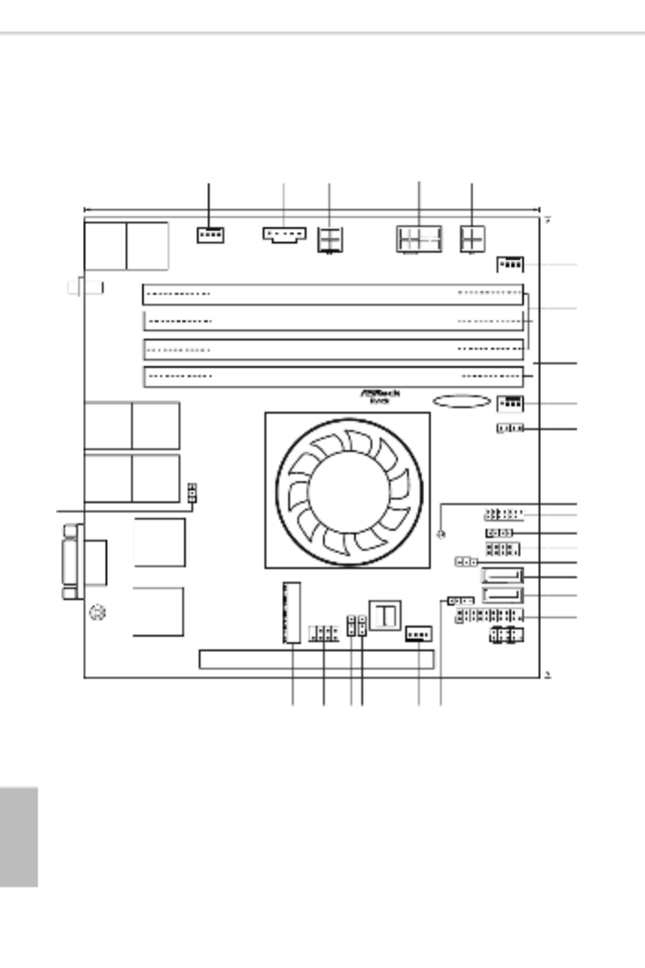
1.4 Motherboard Layout
CH 0_A1 ( 64 bit , 288- pin m , B )odule lueDDR4,
CH 0_A2 ( 64 bit, 288-pin m , Wodule hite)DDR4,
17.0cm (6.7 )in
17.0cm (6.7 in)
5
7
6
FAN3
TP M1
AUX _PA NEL 1
SA PWR 1TA
1
HDL ED ESE T R
PLED PWR BT N
PANE L1
1
SA A_4T
CH 1_B1 ( 64 bi t, 288-pi n m , B )odule lueDDR4,
CH 1_B2 ( 64 bi t, 288-pi n m , Wodule hi te)DDR4,
8
1
PS U_SM B1
9
FAN1
10
BAT1
11
USB_1
SA A_5T
FAN4
NUT 8 0
M2_1
D1 6 2 2D4I
D1 6 0 0D4I- 2 L2T
PCIE7
PE CI 1
1
VGA1
US 3.B 2
Gen1
T: 2USB
B: 1USB
IPMI
LAN
UID1
LAN1 LAN2
1
12
14
13
15
16
17
18
19
20212225
27
11
SPEA KER1
1
1
CLR MOS 1
USB 3_3 _4
11
23
AST2500
FAN2
ATX 112V
SA A_ 0_3T
1
CHA SSIS_ ID0
1
ME_ REC OV ERY1
1
SA TA_S GPI O1
X 2557- AT
LAN3 LAN4
1
LE D_L AN3 _4
2 3
24
1
26
ATXP WR1
HDDP WR1
4
( T o )D16 00D 4I- 2L2 nly ( D1600 D4I-2 L2T o )nly
( T o )D16 00D 4I- 2L2 nly

D1622D4I / D1600D4I-2L2T
7
English
No. Description
1System Fan Connector (FAN2)
2PSU SMBus (PSU_SMB1)
3SATA Power Connector (HDDPWR1)*
4ATX 12V Power Connector (ATX12V1)
5ATX 4-PIN Power Connector (ATXPWR1(ATX 24pin-to-4pin))*
6System Fan Connector (FAN3)
72 x 288-pin DDR4 DIMM Slots (CH0_A1, CH1_B1)
82 x 288-pin DDR4 DIMM Slots (CH0_A2, CH1_B2)
9System Connector (FAN1)
10 Speaker Header (SPEAKER1)
11 Clear CMOS Pad (CLRMOS1)
12 TPM Header (TPM1)
13 Front LAN LED Connector (LED_LAN3_4)
14 Auxiliary Panel Header (AUX_PANEL1)
15 SATA DOM Power Connector (SATAPWR1)
16 SATA3 DOM Connector (SATA_4)
17 SATA3 Connector (SATA_5)
18 USB 3.2 Gen1 Header (USB3_3_4)
19 System Panel Header (PANEL1)
20 USB 2.0 Header (USB_1)
21 System Fan Connector (FAN4)
22 Mini SAS HD Connector (SATA_0_3)
23 ME Recovery Jumper (ME_RECOVERY1)
24 Chassis ID Jumper (CHASSIS_ID0)
25 SATA SGPIO Connector (SATA_SGPIO1)
26 M.2 Socket (M2_1) (Type 2280)
27 CPU PECI Mode Jumper (PECI1)
*Caution: Misconnection between the ATXPWR1 and the HDDPWR1 connectors may permanently damage the
motherboard.

8
English
1.5 Onboard LED Indicators
CH0_A1 ( 64 bit , 288-pin m , B )odule lueDDR4,
CH0_A2 ( 64 bit, 288-pin m , Wodule hite)DDR4,
FAN 3
CH1_B1 ( 64 bit, 288-pin m , B )odule lueDDR4,
CH1_B2 ( 64 bit, 288-pin m , Wodule hite)DDR4,
1
FAN1
BAT 1
FAN 4
NUT 8 0
M2_1
11
SPE AKE R1
CL RM O S1
AST 2500
FAN2
1
1
1
X 2557- AT
1
2
3
46 5
No. Item DescriptionStatus
1 FAN_LED2 Amber FAN2 failed
2 FAN_LED3 Amber FAN3 failed
3 FAN_LED1 Amber FAN1 failed
4 FAN_LED4 Amber FAN4 failed
5 SB_PWR1 STB PWR readyGreen
6 BMC heartbeat LEDBMC_LED1 Green

D1622D4I / D1600D4I-2L2T
9
English
1.6 I/O Panel
2 5
3
6
4
1
7 8
No. No.Description Description
1 Dedicated IPMI LAN Port* 5 LAN RJ-45 Port (LAN1)*
2 USB 3.2 Gen1 Ports (USB3_1_2) 6 10G LAN RJ-45 Port (LAN4)**
(D1600D4I-2L2T only)
3 UID Switch/LED (UID1) 7 10G LAN RJ-45 Port (LAN3)**
(D1600D4I-2L2T only)
4 LAN RJ-45 Port (LAN2)* 8 VGA Port (VGA1)
LAN Port LED Indications
*ere are two LED next to the LAN port. Please refer to the table below for the LAN port
LED indications.
Dedicated IPMI LAN Port LED Indications
Activity / Link LED Speed LED
Status StatusDescription Description
O ONo Link 10M bps connection
Blinking Yellow Data Activity Yellow 100M bps connection
On 1G bps connectionLink Green
ACT/LINK LED
SPEED LED
LAN Port

10
English
**ere are two LEDs on each LAN port. Please refer to the table below for the LAN port
LED indications.
1G LAN Port (LAN1, LAN2) LED Indications
Activity / Link LED Speed LED
Status StatusDescription Description
O ONo Link 10Mbps connection or
no link
Blinking Green Data Activity Yellow 100Mbps connection
On Link Green 1Gbps connection
10G LAN Port (LAN1, LAN2) LED Indications (D1600D4I-2L2T only)
Activity / Link LED Speed LED
Status StatusDescription Description
O ONo Link 100Mbps connection or
no link
Blinking Green Data Activity Yellow 1Gbps connection
On Link Green 10Gbps connection
ACT/LINK LED
SPEED LED
ACT/LINK LED
SPEED LED

D1622D4I / D1600D4I-2L2T
11
English
1.7 Block Diagram
2*rear
LPC BUS
RGMII
PCIe x 16 Gen3
CASE OPEN
D1600D4I-2L2T
Channel B
Intel Processor
SIO
Nuvoton NCT5567
Hewitt Lake –DE
NS D-16XX
PCI-E X16 SLOT7
128-bit Dual-Channel Memory x 4 Slots
DDR4 1866/2133/2400
Channel A
SOC
(system on chip)
X 16
support RDIMM UDIMMs
DRAM
RDIMM: 128GB (32GB Per DIM M)
UDIMM: 64GB (16GB Per DIMM)
NCSI
PCIE x1
Realtek
PHY 8211E
M.2 (2280)
USB2.0
RJ45
CPU Fan x 1
TPM
USB3.0
1*AST2500 ; 1*ASM1074 for U3 HUB
VGA
ASPEEND
AST2500
600MB/S
DDR4 1866/2133/2400
DDR4 1866/2133/2400
DDR4 1866/2133/2400
SATA_5
SATA_4 support SATA DOM
Header
3x system Fan
2 front
1 rear
FAN x 4
D-sub
SPI
SPI FLASH
32 Mb for LAN0
600MB/S
No support NGFF card
SATA_0_3 Mini-SAS HD
TR1
X 4
INTEL LAN X557-AT2 (port3/4)
KR0
PCIe x 4 Gen3
USB3.0 1*ASM1074 for U3 HUB USB3.0 2*front U3
1*front U2
Intel I210 (port1)
PCIE x1
Intel I210 (port2)
PCIE x1
SPI
SPI FLASH
32 Mb for LAN1
BIOS
SWITCH
SPI FLASH
128Mb
SPI

12
English
2*rear
LPC BUS
RGMII
PCIe x 16 Gen3
CASE OPEN
D1622D4I
Channel B
Intel Processor
SIO
Nuvoton NCT5567
Hewitt Lake –DE
NS D-16XX
PCI-E X16 SLOT7 128-bit Dual-Channel Memory x 4 Slots
DDR4 1866/2133/2400
Channel A
SOC
(system on chip)
X 16
support RDIMM UDIMMs
DRAM
RDIMM: 128GB (32GB Per DIMM)
UDIMM: 64GB (16GB Per DIMM)
NCSI
PCIE x1
Realtek
PHY 8211E
M.2 (2280)
USB2.0
RJ45
CPU Fan x 1
TPM
USB3.0
1*AST2500 ; 1*ASM1074 for U3 HUB
VGA
ASPEEND
AST2500
600MB/S
DDR4 1866/2133/2400
DDR4 1866/2133/2400
DDR4 1866/2133/2400
SATA_4 support SATA DOM
Header
3x system Fan
2 front
1 rear
FAN x 4
D-sub
X1
No support NGFF card
SATA_0_3 Mini-SAS HD
X 4
PCIe x 4 Gen3
USB3.0 1*ASM1074 for U3 HUB USB3.0 2*front U3
1*front U2
Intel I210 (port2)
PCIE x1
Intel I210 (port1)
PCIE x1
SPI
SPI FLASH
32 MB
BIOS
SWITCH
SPI FLASH
16MB
SPI
SATA X 1
SWITCH
SATA_5 share M2

D1622D4I / D1600D4I-2L2T
13
English
Chapter 2 Installation
This is a Mini-ITX form factor (6.7'' x 6.7'', 17.0 cm x 17.0 cm) motherboard. Before
you install the motherboard, study the conguration of your chassis to ensure that the
motherboard ts into it.
2.1 Screw Holes
Place screws into the holes indicated by circles to secure the motherboard to the chassis.
2.2 Pre-installation Precautions
Take note of the following precautions before you install motherboard components or
change any motherboard settings.
1. Unplug the power cord from the wall socket before touching any components.
2. To avoid damaging the motherboard’s components due to static electricity, NEVER
place your motherboard directly on the carpet or the like. Also remember to use a
grounded wrist strap or touch a safety grounded object before you handle the compo-
nents.
3. Hold components by the edges and do not touch the ICs.
4. Whenever you uninstall any component, place it on a grounded anti-static pad or in
the bag that comes with the component.
5. When placing screws into the screw holes to secure the motherboard to the chassis,
please do not over-tighten the screws! Doing so may damage the motherboard.
Make sure to unplug the power cord before installing or removing the motherboard. Failure
to do so may cause physical injuries to you and damages to motherboard components.
Do not over-tighten the screws! Doing so may damage the motherboard.
Before you install or remove any component, ensure that the power is switched o or the
power cord is detached from the power supply. Failure to do so may cause severe damage to
the motherboard, peripherals, and/or components.

14
English
2.3 Installation of Memory Modules (DIMM)
is motherboard provides four 288-pin DDR4 (Double Data Rate 4) DIMM slots, and
supports Dual Channel Memory Technology.
Dual Channel Memory Conguration
Priority CH0_A1
(Blue)
CH0_A2
(White)
CH1_B1
(Blue)
CH1_B2
(White)
1 Populated Populated
2 Populated Populated Populated Populated
*Since installing three memory modules is NOT supported on this motherboard, we suggest not using
this conguration.
1. For dual channel conguration, you always need to install identical (the same brand,
speed, size and chip-type) DDR4 DIMM pairs.
2. It is not allowed to install a DDR, DDR2 or DDR3 memory module into a DDR4 slot;
otherwise, this motherboard and DIMM may be damaged.
3. Please install the memory module on CH0_A1 for the rst priority.
4. To activate Dual Channel Memory Technology, please follow the “Dual Channel Memory
Conguration” table below.
e DIMM only ts in one correct orientation. It will cause permanent damage to the
motherboard and the DIMM if you force the DIMM into the slot at incorrect orientation.

D1622D4I / D1600D4I-2L2T
15
English
1
2
3

16
English
2.4 Expansion Slots (PCI Express Slots)
ere is 1 PCI Express slots on this motherboard.
PCIE slot:
PCIE7 (PCIE 3.0 x16 slot) is used for PCI Express x16 lane width cards.
Installing an expansion card
Step 1. Before installing an expansion card, please make sure that the power
supply is switched o or the power cord is unplugged. Please read the
documentation of the expansion card and make necessary hardware
settings for the card before you start the installation.
Step 2. Remove the system unit cover (if your motherboard is already installed
in a chassis).
Step 3. Remove the bracket facing the slot that you intend to use. Keep the
screws for later use.
Step 4. Align the card connector with the slot and press rmly until the card is
completely seated on the slot.
Step 5. Fasten the card to the chassis with screws.
Step 6. Replace the system cover.

D1622D4I / D1600D4I-2L2T
17
English
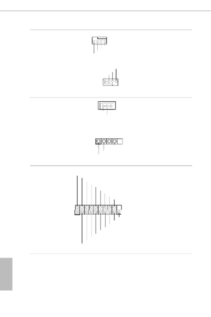
2.5 Jumper Setup
e illustration shows how jumpers are setup. When the jumper cap is placed on
the pins, the jumper is “Short”. If no jumper cap is placed on the pins, the jumper
is “Open”. e illustration shows a 3-pin jumper whose pin1 and pin2 are “Short”
when a jumper cap is placed on these 2 pins.
ME Recovery Jumper
(3-pin ME_RECOVERY1)
(see p.6, No. 21)
Normal Mode (Default)
ME Recovery Mode
CPU PECI Mode Jumper
(3-pin PECI1)
(see p.6, No. 27) CPU PECI connected to PCH CPU PECI connected to
BMC (Default)
CHASSIS ID Jumper
(3-pin CHASSIS_ID0)
(see p.6, No. 24) Board Level SKU (Default) Reserved for system level use

18
English
Onboard headers and connectors are NOT jumpers. Do NOT place jumper caps over these
headers and connectors. Placing jumper caps over the headers and connectors will cause
permanent damage to the motherboard.
2.6 Onboard Headers and Connectors
Serial ATA3 Connectors
(SATA_4)
(see p.6, No. 16)
(SATA_5)
(see p.6, No. 17)
ese two Serial ATA3 (SATA3)
connectors support SATA
data cables for internal storage
devices. e current SATA3
interface allows up to 6.0 Gb/s
data transfer rate.
Serial ATA3 DOM
Connector
(SATA_5)
(see p.6, No. 16)
e SATA3 DOM
connector supports both
a SATA DOM (Disk-On-
Module) and a SATA
data cable for internal
storage devices.
Mini-SAS HD Connector
(SATA_0_3)
(see p.6, No. 22)
SA A_0_ 3T
e connector supports
MiniSAS-to-SATA
data cables for internal
storage devices with up
to 6.0 Gb/s data transfer
rate.
Chassis Speaker Header
(4-pin SPEAKER1)
(see p.6, No. 10)
1
+5V
DU M M Y
DU M M Y
SPEA K ER
Please connect the chassis
speaker to this header.
TPM Header
(13-pin TPM1)
(see p.6, No. 12)
+3V
+3V
GND
LAD3
LFR AME
GND33M
RS T
LAD0
LAD2
GND
+3V
LAD1
1
is connector supports Trusted
Platform Module (TPM) system,
which can securely store keys,
digital certicates, passwords,
and data. A TPM system also
helps enhance network security,
protects digital identities, and
ensures platform integrity.
SATA_4
SATA_5
SATA_4

D1622D4I / D1600D4I-2L2T
19
English
PSU SMBus
(PSU_SMB1)
(see p.6, No. 2)
+3V
1
GND
AL E R T
SMBCLK
SMBDATA
PSU SMBus monitors the
status of the power supply, fan
and system temperature.
System Panel Header
(9-pin PANEL1)
(see p.6, No. 19)
GND
R #ES ET
PWRBT N#
PLE D-
PLE D+
GND
HD LE D-
HD LE D+
1
GND
is header accommodates
several system front panel func-
tions.
Auxiliary Panel Header
(9-pin AUX_PANEL1)
(see p.6, No. 14)
BLK_TX RX
SYS TEM_FAULT_LED_P
LA N2_LIN K_P
LA N1_LIN K_P
ALED1
SYS TEM_FAULT_LED_N
GND
R_CAS E OPEN
1
is header supports multiple
functions on the front panel,
including front panel SMB,
internet status indicator.
PWRBTN (Power Switch):
Connect to the power switch on the chassis front panel. You may congure the way to turn
o your system using the power switch.
RESET (Reset Switch):
Connect to the reset switch on the chassis front panel. Press the reset switch to restart the
computer if the computer freezes and fails to perform a normal restart.
PLED (System Power LED):
Connect to the power status indicator on the chassis front panel. e LED is on when the
system is operating. e LED is o when the system is in powered o (S5).
HDLED (Hard Drive Activity LED):
Connect to the hard drive activity LED on the chassis front panel. e LED is on when the
hard drive is reading or writing data.
e front panel design may dier by chassis. A front panel module mainly consists of power
switch, reset switch, power LED, hard drive activity LED, speaker and etc. When connect-
ing your chassis front panel module to this header, make sure the wire assignments and the
pin assignments are matched correctly.
20
English
System Fan Connectors
(4-pin FAN1)
(see p.6, No. 9)
(4-pin FAN2)
(see p.6, No. 1)
(4-pin FAN3)
(see p.6, No. 6)
(4-pin FAN4)
(see p.6, No. 21)
FAN_ SPEED
FA LN_ SPEED_ CONTRO
FAN_VOLTAGE
GND
4 3 2 1
F DAN_SPEE
F LAN_SPEED_CONTRO
GND
FAN_ VOLTAGE
1 2 3 4
Please connect the fan cables to
the fan connectors and match
the black wire to the ground pin.
All fans supports Fan Control.
SATA DOM Power
Connector
(3-pin SATAPWR1)
(see p.6, No. 15)
GND
N C/
+5V
Please connect the power cable
on the SATA DOM to this
connector.
USB 2.0 Header
(4-pin USB_1)
(see p.6, No. 20)
GND
P+0
P-0
U RSB_PW
1ere is one USB 2.0 header on
this motherboard, and it can
support one USB 2.0 port.
USB 3.2 Gen1 Header
(19-pin USB3_3_4)
(see p.6, No. 18)
Besides two default USB 3.2
Gen1 ports on the I/O panel,
there is one USB 3.2 Gen1
header on this motherboard.
is USB 3.2 Gen1 header
can support two USB 3.2 Gen1
ports.
1
Dummy
GND
GND
Vb us
GND
GND
IntA_PA_SSRX+
Vb us
Dummy
Dummy
IntA_PA_SST X+
IntA_PA_SST X-
IntA_PA_SSRX-
IntA_PB_SSRX
-
IntA_PB_SSRX+
IntA_PB_SST X-
IntA_PBA_SST X+
IntA_PB_D-
IntA_PB_D+
D1622D4I / D1600D4I-2L2T
21
English
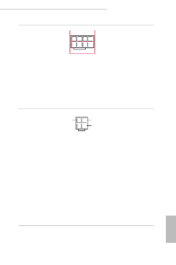
ATX 12V Power
Connector
(8-pin ATX12V1)
(see p.6, No. 4)
4
8
1
5
12V
GND e motherboard provides one
8-pin 12V power connector
which is a required input for
either DC-IN 12V or ATX +12V
power source.
When using ATX power, it is
necessary to use a 24pin-to-4pin
power cable to connect between
the 24pin power connector
of PSU and the ATXPWR1
connector on the motherboard
for power supply and signal
communication.
ATX 4-PIN Power
Connector
(4-pin ATXPWR1
(ATX 24pin-to-4pin))
(see p.6, No. 5)
e motherboard provides one
4-pin power/signal connector
which is a required input for
ATX power source.
When using ATX power, it is
necessary to use a 24pin-to-4pin
power cable to connect between
the 24pin power connector
of PSU and the ATXPWR1
connector on the motherboard
for power supply and signal
communication.
For DC-IN 12V application, it
is not necessary to use this ATX
4-PIN power connector.
*Caution: Misconnection between the
ATXPWR1 and the HDDPWR1 con-
nectors may permanently damage the
motherboard.
1 2
3 4
PSON#
GND
ATX_PWROK
ATX_+5VSB

22
English
SATA Power Connector
(DC-IN Mode)
(4-pin HDDPWR1)
(see p.6, No. 3)
1 2
34
+5V
GND
+12V
GND
Please use a SATA power cable
to connect this SATA Power
Connector and your SATA
HDD for supplying power
from the motherboard, when
using DC-IN mode without
SATA power supply.
*Caution: Misconnection between the
ATXPWR1 and the HDDPWR1 con-
nectors may permanently damage the
motherboard.
Serial General Purpose
Input/Output Header
(7-pin SATA_SGPIO1)
(see p.6, No. 25) 1
SLOAD
SCLOCK
GND
GND
SDATAOUT
is header supports Serial
Link interface for onboard
SATA connections.
LAN LED Connector
(LED_LAN3_4)
(see p.6, No. 13)
1
LAN 4_LINK
LED _ P WR
LED _ P WR
LAN 3_LINK
is 4-pin connector is used for
the front LAN status indicator.
Clear CMOS Pad
(CLRMOS1)
(see p.6, No. 11)
is allows you to clear the
data in CMOS. To clear CMOS,
take out the CMOS battery and
short the Clear CMOS Pad.

D1622D4I / D1600D4I-2L2T
23
English
2.7 ATX PSU / DC-IN Power Connections
is motherboard supports both +12V DC and ATX power input. Please refer to the
table below for the required connections between the motherboard and the power
supply.
Connector DC-IN ATX PSU
12V 8pin O O
ATX 4pin X
O
(with the bundled ATX
24pin-to-4pin converter cable)
PSU
12V 8pin ATX 4pin
(via a 24pin-to-4pin
Converter Cable)
PSU
12V 8pin
DC-IN ATX PSU
e following diagram illustrates how to connect the bundled ATX 24pin-to-4pin
converter cable.
24pin-to-4pin
Converter Cable

24
English
2.8 Unit Identication purpose LED/Switch
With the UID button, You are able to locate the server you’re working on from behind
a rack of servers.
Unit Identication
purpose LED/Switch
(UID1)
When the UID button on the
front or rear panel is pressed,
the front/rear UID blue LED
indicator will be turned on.
Press the UID button again to
turn o the indicator.

D1622D4I / D1600D4I-2L2T
25
English
2.9 Dual LAN and Teaming Operation Guide
Dual LAN with Teaming enabled on this motherboard allows two single
connections to act as one single connection for twice the transmission bandwidth,
making data transmission more eective and improving the quality of transmission
of distant images. Fault tolerance on the dual LAN network prevents network
downtime by transferring the workload from a failed port to a working port.
Before setting up Teaming, please make sure whether your Switch (or Router)
supports Teaming (IEEE 802.3ad Link Aggregation). You can specify a preferred
adapter in Intel PROSet. Under normal conditions, the Primary adapter handles all
non-TCP/IP trac. e Secondary adapter will receive fallback trac if the primary
fails. If the Preferred Primary adapter fails, but is later restored to an active status,
control is automatically switched back to the Preferred Primary adapter.
Step 1
From Device Manager, open the properties of a team.
Step 2
Click the Settings tab.
Step 3
Click the button.Modify Team
Step 4
Select the adapter you want to be the primary adapter and click the Set Primary
button.
If you do not specify a preferred primary adapter, the soware will choose an
adapter of the highest capability (model and speed) to act as the default primary. If
a failover occurs, another adapter becomes the primary. e adapter will, however,
rejoin the team as a non-primary.
e speed of transmission is subject to the actual network environment or status even with
Teaming enable d.

26
English
2.10 M.2_SSD Module Installation Guide
e Hyper M.2 Socket (M2_1, Key M) supports type 2280 M.2 PCI Express module up to
Gen3 p32-x4 (8GT/s x4).
Installing the M.2_SSD Module
Step 1
Prepare a M.2_SSD module and the
screw.
20
o
Step 2
Gently insert the M.2 SSD module
into the M.2 slot. Please be aware
that the M.2 SSD module only ts in
one orientation.
Step 3
Tighten the screw with a screwdriver
to secure the module into place.
Please do not overtighten the screw as
this might damage the module.

D1622D4I / D1600D4I-2L2T
27
English
Chapter 3 UEFI Setup Utility
3.1 Introduction
is section explains how to use the UEFI SETUP UTILITY to congure your system. e
UEFI chip on the motherboard stores the UEFI SETUP UTILITY. You may run the UEFI
SETUP UTILITY when you start up the computer. Please press <F2> or <Del> during the
Power-On-Self-Test (POST) to enter the UEFI SETUP UTILITY; otherwise, POST will
continue with its test routines.
If you wish to enter the UEFI SETUP UTILITY aer POST, restart the system by pressing
<Ctrl> + <Alt> + <Delete>, or by pressing the reset button on the system chassis. You may
also restart by turning the system o and then back on.
3.1.1 UEFI Menu Bar
e top of the screen has a menu bar with the following selections:
Item Description
Main To set up the system time/date information
Advanced To set up the advanced UEFI features
Security To set up the security features
Boot To set up the default system device to locate and load the
Operating System
Event Logs For event log conguration
Server Mgmt To manage the server
Exit To exit the current screen or the UEFI SETUP UTILITY
Use < > key or < > key to choose among the selections on the menu bar, and
then press <Enter> to get into the sub screen.
Because the UEFI soware is constantly being updated, the following UEFI setup screens
and descriptions are for reference purpose only, and they may not exactly match what you
see on your screen.

28
English
3.1.2 Navigation Keys
Please check the following table for the function description of each navigation key.
Navigation Key(s) Function Description
/ Moves cursor le or right to select Screens
/ Moves cursor up or down to select items
+ / - To change option for the selected items
<Tab> Switch to next function
<Enter> To bring up the selected screen
<PGUP> Go to the previous page
<PGDN> Go to the next page
<HOME> Go to the top of the screen
<END> Go to the bottom of the screen
<F1> To display the General Help Screen
<F7> Discard changes and exit the UEFI SETUP UTILITY
<F9> Load optimal default values for all the settings
<F10> Save changes and exit the UEFI SETUP UTILITY
<F12> Print screen
<ESC> Jump to the Exit Screen or exit the current screen

D1622D4I / D1600D4I-2L2T
29
English
3.2 Main Screen
Once you enter the UEFI SETUP UTILITY, the Main screen will appear and display the
system overview. e Main screen provides system overview information and allows you
to set the system time and date.

30
English
Setting wrong values in this section may cause the system to malfunction.
3.3 Advanced Screen
In this section, you may set the congurations for the following items: CPU Conguration,
DRAM Conguration, Chipset Conguration, Storage Conguration, ACPI Congura-
tion, USB Conguration, Super IO Conguration, Serial Port Console Redirection, H/W
Monitor, Runtime Error Logging, Intel SPS Conguration and Instant Flash.

D1622D4I / D1600D4I-2L2T
31
English
3.3.1 CPU Conguration
Intel SpeedStep Technology
Intel SpeedStep technology allows processors to switch between multiple frequencies and
voltage points for better power saving and heat dissipation. CPU turbo ratio can be xed
when Intel SpeedStep Technology set Disabled and Intel Turbo Boost Technology set En-
abled.
Please note that enabling this function may reduce CPU voltage and lead to system stability
or compatibility issues with some power supplies. Please set this item to [Disabled] if above
issues occur.
Intel Turbo Boost Technology
Intel Turbo Boost Technology enables the processor to run above its base operating fre-
quency when the operating system requests the highest performance state.
Long Duration Power Limit
Congure Package Power Limit 1 in watts. When the limit is exceeded, the CPU ratio will
be lowered aer a period of time. A lower limit can protect the CPU and save power, while
a higher limit may improve performance.
Long Duration Maintained
Congure the period of time until the CPU ratio is lowered when the Long Duration Power

D1622D4I / D1600D4I-2L2T
33
English
CPU C6 State Support
Enable C6 deep sleep state for lower power consumption.
Enhanced Halt State(C1E)
Enable Enhanced Halt State (C1E) for lower power consumption.
Hardware P-States
Disable: Hardware chooses a P-state based on OS Request (Legacy P-States)
Native Mode: Hardware chooses a P-state based on OS guidance
Out of Band Mode: Hardware autonomously chooses a P-state (no OS guidance)
AES-NI
Use this item to enable or disable AES-NI support.
CPU Thermal Throttling
Enable CPU internal thermal control mechanisms to keep the CPU from overheating.

34
English
3.3.2 DRAM Conguration
Enforce POR
Enforce POR - Enforces Plan Of Record restrictions for DDR4 frequency and voltage
programming.
Disable - Disables this feature.
DRAM Frequency
If [Auto] is selected, the motherboard will detect the memory module(s) inserted and
assign the appropriate frequency automatically.
Channel Interleaving
Select to congure Channel Interleaving settings.
Rank Interleaving
Select to congure Rank Interleaving settings.

D1622D4I / D1600D4I-2L2T
35
English
3.3.3 Chipset Conguration
MMCFG Base
Use this item to select MMCFG Base.
MMIO High Base
Use this item to select MMIO High Base.
MMIO High Size
Use this item to select MMIO High Size.
Above 4G Decoding
Enable or disable 64bit capable Devices to be decoded in Above 4G Address Space (only if
the system supports 64 bit PCI decoding).
Primary Graphics Adapter
If PCI Express graphics card is installed on the motherboard, you may use this option to
select PCI Express or Onboard VGA as the primary graphics adapter.
*If no PCI Express graphics card is installed, [Onboard VGA] is the default graphics adapter. ere is no screen
on monitor even if a HDMI display is connected. Select [Onboard Hdmi] instead to use HDMI as output source.
Onboard LAN1
Use this to enable or disable the Onboard LAN function. e default value is [Auto].
Specyfikacje produktu
| Marka: | Asrock |
| Kategoria: | serwer |
| Model: | Rack D1622D4I |
Potrzebujesz pomocy?
Jeśli potrzebujesz pomocy z Asrock Rack D1622D4I, zadaj pytanie poniżej, a inni użytkownicy Ci odpowiedzą
Instrukcje serwer Asrock

11 Lutego 2025
11 Lutego 2025
11 Lutego 2025
11 Lutego 2025
11 Lutego 2025
11 Lutego 2025
11 Lutego 2025
11 Lutego 2025
11 Lutego 2025
Instrukcje serwer
- serwer Sony
- serwer Supermicro
- serwer Lenovo
- serwer Gigabyte
- serwer Acer
- serwer Technics
- serwer Hikvision
- serwer Fujitsu
- serwer Conceptronic
- serwer StarTech.com
- serwer Asus
- serwer Medion
- serwer TRENDnet
- serwer MSI
- serwer Toshiba
- serwer D-Link
- serwer ATen
- serwer APC
- serwer HP
- serwer Tripp Lite
- serwer Cisco
- serwer Moxa
- serwer Synology
- serwer Lindy
- serwer ZyXEL
- serwer Dell
- serwer Linksys
- serwer Digitus
- serwer Vimar
- serwer Netgear
- serwer Black Box
- serwer ELAC
- serwer Intellinet
- serwer HGST
- serwer Revox
- serwer Naim
- serwer SEH
- serwer Planet
- serwer NEC
- serwer LevelOne
- serwer Digi
- serwer Axis
- serwer Abus
- serwer Rocstor
- serwer Western Digital
- serwer Smart-AVI
- serwer Promise Technology
- serwer QNAP
- serwer Chenbro Micom
- serwer Allnet
- serwer Veritas
- serwer IStarUSA
- serwer Silverstone
- serwer Ernitec
- serwer AVerMedia
- serwer Atlona
- serwer Gefen
- serwer Hanwha
- serwer Quantum
- serwer Blackmagic Design
- serwer Kathrein
- serwer Eaton
- serwer Monacor
- serwer Sonnet
- serwer In Win
- serwer Teo
- serwer Megasat
- serwer Areca
- serwer Kramer
- serwer KanexPro
- serwer Raritan
- serwer AMX
- serwer C2G
- serwer Acti
- serwer Sitecom
- serwer Maxdata
- serwer Matrox
- serwer Flir
- serwer Buffalo
- serwer GeoVision
- serwer LaCie
- serwer Valcom
- serwer Asustor
- serwer Intel
- serwer Fantec
- serwer Freecom
- serwer Seagate
- serwer Iomega
- serwer Luxman
- serwer Ibm
- serwer Provision ISR
- serwer TAIDEN
- serwer SIIG
- serwer Advantech
- serwer Extron
- serwer Avocent
- serwer Teradek
- serwer Silex
- serwer Sun
- serwer MvixUSA
- serwer Dual Bay
- serwer Raidsonic
- serwer EMC
- serwer Infortrend
- serwer Opengear
- serwer G-Technology
- serwer EXSYS
- serwer Middle Atlantic
- serwer Mr. Signal
- serwer Atlantis Land
- serwer Lantronix
- serwer NETSCOUT
- serwer Mobotix
- serwer Origin Storage
Najnowsze instrukcje dla serwer

9 Kwietnia 2025
2 Kwietnia 2025

2 Kwietnia 2025
2 Kwietnia 2025
28 Marca 2025
28 Marca 2025
28 Marca 2025

10 Marca 2025
10 Marca 2025
10 Marca 2025