Instrukcja obsługi Areca ARC-8050T3U-4
Przeczytaj poniżej 📖 instrukcję obsługi w języku polskim dla Areca ARC-8050T3U-4 (169 stron) w kategorii serwer. Ta instrukcja była pomocna dla 16 osób i została oceniona przez 2 użytkowników na średnio 4.5 gwiazdek
Strona 1/169

ARC-8050T3U
(4/6/8/12-bays ThunderboltTM 3 RAID Storage)
User Manual
Version: 2.5
Issue Date: June, 2022
Thunderbolt™ Prod
uct

Copyright and Trademarks
The information regarding products in this manual is subject to change
without prior notice and does not represent a commitment on the part
of the vendor, who assumes no liability or responsibility for any errors
that may appear in this manual. All brands and trademarks are the
properties of their respective owners. This manual contains materials
protected under International Copyright Conventions. All rights
reserved. No part of this manual may be reproduced in any form or by
any means, electronic or mechanical, including photocopying, without
the written permission of the manufacturer and the author.
FCC Statement
This equipment has been tested and found to comply with the lim-
its for a Class B digital device, pursuant to part 15 of the FCC Rules.
These limits are designed to provide reasonable protection against in-
terference in a residential installation. This equipment generates, uses,
and can radiate radio frequency energy and, if not installed and used
in accordance with the instructions, may cause harmful interference to
radio communications. However, there is no guarantee that interfer-
ence will not occur in a particular installation.
Manufacturer’s Declaration for CE Certication
We conrm ARC-8050T3U series has been tested and found com-
ply with the requirements set up in the council directive on the ap-
proximation of the low of member state relating to the EMC Direc-
tive2004/108/EC. For the evaluation regarding to the electromagnetic
compatibility, the following standards where applied:
EN 55022: 2006, Class B
EN 61000-3-2: 2006
EN 61000-3-3: 1995+A1: 2001+A2: 2005
EN 55024:1998+A1:2001=A2:2003
IEC61000-4-2: 2001
IEC61000-4-3: 2006
IEC61000-4-4: 2004
IEC61000-4-5: 2005
IEC61000-4-6: 2006
IEC61000-4-8: 2001
IEC61000-4-11: 2004

Contents
1. Introduction 8 ................................................................
1.1 Overview 8 .........................................................................
1.2 Features 10 ........................................................................
2. Installation 13 ................................................................
2.1 Before You First Installing................................................. 13
2.2 Summary of RAID Storage Setup Steps .............................. 14
• For macOS .................................................................... 14
• For Windows .................................................................. 15
2.3 RAID Storage View 16 ..........................................................
2.4 Setting Up RAID Storage .................................................. 23
2.4.1 Physically Install RAID Storage and Drives 23 .....................
2.4.2 Mac Users ................................................................. 32
2.4.2.1 Install Areca driver for Mac 32 .....................................
2.4.2.2 Install the MRAID Utility ......................................... 38
2.4.2.3 Congure RAID Volumes ......................................... 43
2.4.2.4 Format and Partition RAID Volumes 46 ..........................
2.4.2.5 Make A Bootable RAID Volume 48 ................................
2.4.2.6 Unmounting RAID Volumes ..................................... 48
2.4.3 Windows Users .......................................................... 50
2.4.3.1 Install the Thunderbolt Software 50 ..............................
2.4.3.2 Congure RAID Volumes ......................................... 54
2.4.3.3 Format RAID Volumes 57 ............................................
2.4.3.4 Unmounting RAID Volumes ..................................... 57
3. ArcHTTP Conguration .............................................. 59
• General Conguration ..................................................... 59
• Mail (Alert by Mail) Conguration ..................................... 60
• SNMP Traps Conguration ............................................... 61
• Rescan Device Conguration ............................................ 63
• Collect Support Data 63 ......................................................
4. Web Browser-based Conguration ........................... 64
4.1 Start-up McRAID Storage Manager 65 ....................................
• McRAID Storage Manager from Local Administration (In-Band)
...................................................................................... 65
• McRAID Storage Manager Through LAN Port (Out-of-Band) 66 ..
4.2 McRAID Main Window 66 ......................................................
4.3 Main Menu 67 ....................................................................
4.4 Quick Function 67 ................................................................

4.5 Raid Set Functions 68 ..........................................................
4.5.1 Create Raid Set ......................................................... 68
4.5.2 Delete Raid Set .......................................................... 69
4.5.3 Expand Raid Set ......................................................... 70
4.5.4 Ofine Raid Set .......................................................... 71
4.5.5 Rename Raid Set ........................................................ 71
4.5.6 Activate Incomplete Raid Set 72 .......................................
4.5.7 Create Hot Spare 72 .......................................................
4.5.8 Delete Hot Spare 73 ........................................................
4.5.9 Rescue Raid Set ......................................................... 73
4.6 Volume Set Functions ...................................................... 75
4.6.1 Create Volume Set (0/1/10/3/5/6) 75 ...............................
4.6.2 Create Raid30/50/60 (Volume Set 30/50/60) ................. 80
4.6.3 Delete Volume Set 80 ......................................................
4.6.4 Modify Volume Set 81 ......................................................
4.6.4.1 Volume Growth 82 .....................................................
4.6.4.2 Volume Set Migration ............................................. 82
4.6.4.3 Volume Write Protection 83 .........................................
4.6.5 Check Volume Set 83 ......................................................
4.6.6 Schedule Volume Check 84 ..............................................
4.6.8 Download Volume Key File 85 ...........................................
4.7 Security Function 86 ............................................................
4.7.1 Create SED RAID Set 86 .................................................
4.7.2 Delete SED RAID Set 87 .................................................
4.7.3 Delete ISE RAID Set 87 ..................................................
4.7.4 Security Key Setup 88 .....................................................
4.7.4.1 SED Key Management-Creation 88 ...............................
4.7.4.2 SED Key Management-Modication .......................... 89
4.7.5 Import Security Key 90 ....................................................
4.7.6 Erase Failed Disk 91 ........................................................
4.7.7 RevertSP 92 ...................................................................
4.8 Physical Drive 93 ................................................................
4.8.1 Create Pass-Through Disk 93 ............................................
4.8.2 Modify Pass-Through Disk 93 ............................................
4.8.3 Delete Pass-Through Disk 94 ............................................
4.8.4 Clone Disk 94 .................................................................
4.8.4.1 Clone And Replace 95 .................................................
4.8.4.2 Clone Only 95 ...........................................................
4.8.5 Abort Cloning 96 .............................................................
4.8.6 Set Disk To Be Failed 96 ..................................................
4.8.7 Activate Failed Disk 96 ....................................................
4.8.8 Identify Enclosure 97 ......................................................

4.8.9 Identify Drive 97 ............................................................
4.9 System Controls 98 .............................................................
4.9.1 System Cong ........................................................... 98
• System Beeper Setting ................................................... 98
• Background Task Priority ................................................. 98
• JBOD/RAID Conguration ................................................ 98
• SATA NCQ Support 99 .........................................................
• HDD Read Ahead Cache 99 ..................................................
• Volume Data Read Ahead ............................................... 99
• HDD Queue Depth ......................................................... 99
• Empty HDD Slot LED ...................................................... 99
• Max Command Length .................................................. 100
• Auto Activate Incomplete Raid ....................................... 100
• Disk Write Cache Mode ................................................. 100
• Write Same For Initialization .......................................... 100
• Hot Plugged Disk For Rebuilding ..................................... 100
• Disk Capacity Truncation Mode ....................................... 101
• Smart Option For HDD .................................................. 101
• Smart Polling Interval ................................................... 102
4.9.2 Advanced Conguration ............................................. 102
• TLER Setting ............................................................... 103
• Timeout Setting ........................................................... 103
• Number of Retries ........................................................ 103
• Buffer Threshold .......................................................... 103
• Read Ahead Count ........................................................ 104
• Read Ahead Requests ................................................... 104
• Amount of Read Ahead ................................................. 104
• Number of AV Stream ................................................... 104
• Optimize AV Recording .................................................. 105
• Read Performance Margin .............................................. 105
• Read And Discard Parity Data ........................................ 107
• BIOS Selection............................................................. 107
• Host Command Queue Mode .......................................... 108
• Save SED Key In Controller ........................................... 108
• Fail Disk For Reading Error ............................................ 108
• Thunderbolt Receive Sleep Request ................................ 109
4.9.3 HDD Power Management 110 ...........................................
• Stagger Power On Control 110 ............................................
• Time To Hdd Low Power Idle 111 .........................................
• Time To Hdd Low RPM Mode 111 .........................................
• SATA Power Up In Standby ........................................... 111
• Delay for Phy to Stable ................................................ 112

• SSD Stop Unit When Shutdown ..................................... 112
4.9.4 Ethernet Conguration ............................................. 113
• DHCP Function 113 .............................................................
• Local IP address 114 ...........................................................
• Gateway IP address ...................................................... 114
• Subnet Mask 114 ...............................................................
• HTTP Port Number 114 ........................................................
• Telnet Port Number 114 ......................................................
• SMTP Port Number 114 .......................................................
4.9.5 Alert By Mail Conguration ....................................... 115
4.9.6 SNMP Conguration .................................................. 115
4.9.7 NTP Conguration .................................................... 116
• NTP Sever Address ....................................................... 116
• Time Zone ................................................................... 116
• Automatic Daylight Saving............................................. 117
4.9.8 View Events/Mute Beeper 117 ..........................................
4.9.9 Generate Test Event 117 .................................................
4.9.10 Clear Events Buffer 118 .................................................
4.9.11 Modify Password 118 .....................................................
4.9.12 Update Firmware ................................................... 119
4.10 Information 120 ................................................................
4.10.1 Raid Set Hierarchy 120 ..................................................
4.10.1.1 Hdd Xfer Speed 120 .................................................
4.10.2 SAS Chip Information 121 ..............................................
4.10.3 System Information 122 ................................................
4.10.4 Hardware Monitor 122 ...................................................
Appendix A 123 .................................................................
Upgrading Flash ROM Update Process .................................... 123
Appendix B 126 ..................................................................
Battery Backup Module (ARC-6120BA-T021-T3) 126 ......................
B-1 BBM Connector and Components 126 ................................
B-2 Status of BBM 126 ..........................................................
B-3 Installation 127 ..............................................................
Appendix C 132 ..................................................................
SNMP Operation & Installation 132 ..............................................
Appendix D 137 ..................................................................
Event Notication Congurations ........................................ 137
A. Device Event 137 ..............................................................
B. Volume Event 138 .............................................................
C. RAID Set Event 139 ..........................................................
D. Hardware Monitor Event .............................................. 139
Appendix E 141 ..................................................................
Self-Encrypting Disk (SED) Encryption 141 .................................
Appendix F 147 ..................................................................
Full Volume Encryption ...................................................... 147
Appendix G 152 ..................................................................
RAID Concept 152 ....................................................................
RAID Set 152 .........................................................................
Volume Set ...................................................................... 152
Ease of Use Features ......................................................... 153
• Foreground Availability/Background Initialization .............. 153
• Online Array Roaming 153 ...................................................
• Online Capacity Expansion 153 .............................................
• Online RAID Level and Stripe Size Migration .................... 155
• Online Volume Expansion 156 ..............................................
High Availability ............................................................... 156
• Global/Local Hot Spares 156 ................................................
• Hot-Swap Disk Drive Support 157 .........................................
• Auto Declare Hot-Spare 157 ...............................................
• Auto Rebuilding ........................................................... 158
• Adjustable Rebuild Priority 158 .............................................
High Reliability 159 .................................................................
• Hard Drive Failure Prediction 159 ..........................................
• Auto Reassign Sector 159 ....................................................
• Consistency Check 160 .......................................................
Data Protection 160 ................................................................
• Battery Backup 160 ...........................................................
• Recovery ROM ............................................................. 161
Appendix H 162 ..................................................................
Understanding RAID .......................................................... 162
RAID 0 162 ............................................................................
RAID 1 163 ............................................................................
RAID 10(1E) 164 ....................................................................
RAID 3 164 ............................................................................
RAID 5 165 ............................................................................
RAID 6 166 ............................................................................
RAID x0 166 ..........................................................................
Single Disk (Pass-Through Disk) ......................................... 167
Summary of RAID Levels 168 ...................................................
INTRODUCTION
8
1. Introduction
This section presents a brief overview of the Thunderbolt 3 desktop
SAS/SATA RAID storages, ARC-8050T3U series.
1.1 Overview
Unleash Your Creativity Faster Than Ever
Thunderbolt™ 3 brings Thunderbolt to USB-C at speeds up to 40
Gbps, creating one compact port that does it all – delivering the
fastest, most versatile connection to any dock, display, or data
device. ARC-8050T3U is equipped with dual Thunderbolt 3 ports for
connecting to any Thunderbolt 3-enabled host and offers an addi-
tional Thunderbolt 3 port for daisy-chaining other peripherals, while
also supplying power for quick notebook charging. The Thunderbolt
daisy-chaining allows connection of up to six devices, so customers
can connect ARC-8050T3U for massive amounts of video storage
with a single Thunderbolt connection to their host computer. If an
ARC-8050T3U is plugged in a USB-C (or) USB X.X computer port, a
USB device controller inside the ARC-8050T3U-enabled system
is activated, and the inside USB device controller drives USB (2.0,
3.2 Gen 1, or 3.2 Gen 2) signals to the USB-C port. In this condi-
tion, the ARC-8050T3U Thunderbolt 3 port behaves exactly like a
typical USB-C 3.2-enabled connector. The ARC-8050T3U also sports
a full sized DisplayPort 1.4 video output on its rear, allowing for a
quick and easy 8K 30Hz display setup.
Unparalleled Performance for 4K Workow
ARC-8050T3U is the most complete 4/6/8/12-bay Thunderbolt
3 desktop SAS/SATA RAID storage with RAID control capabilities
solution for both PC and Mac. ARC-8050T3U incorporated on-board
RAID-On-Chip and ECC SDRAM memory to deliver true high perfor-
mance hardware RAID protection against drive failure.This combi-
nation helps to provide a high performance storage device perfect
for the video editor working with Real time multi-stream HD and 4K
workows. It is so quick it allows for 4K displays at the same time
as daisy chaining ARC-8050T3U and doing a simultaneous 4K out-
put and le transfers while maintaining maximum throughput.

INTRODUCTION
9
Thunderbolt 3 and USB 3.2 Gen2 Ready
ARC-8050T3U Thunderbolt 3 port supports both Thunderbolt 3 &
USB 3.2 Gen 2 protocol.

INTRODUCTION
10
1.2 Features
Controller Architecture
• 800 MHz one core (for ARC-8050T3U-4) / 1.2 GHz dual core (for
ARC-8050T3U-6/8/12) ROC for RAID core and SAS microcode
• 1GB DDR3-800 (for ARC-8050T3U-4) / 2GB on-board DDR3-1866
(for ARC-8050T3U-6/8/12) SDRAM with ECC protection
• Redundant ash image for adapter availability
• System status indication through LCD, LED and alarm buzzer
RAID Features
• RAID level 0, 1, 1E, 3, 5, 6, 10, 30, 50, 60, Single Disk or JBOD
• Multiple RAID selection
• Support up to 1MB stripe size
• Online array roaming
• Online RAID level/stripe size migration
• Support global hot spare and local hot spare
• Instant availability and background initialization
• Advanced conguration for smooth data streaming
• Disk scrubbing/ array verify scheduling support
• Multiple pairs SSD/HDD disk clone function
• SSD automatic monitor clone (AMC) support
• SED (Self-encrypting drives) function support
• Support HDD rmware update
• Support for native 4K and 512 byte sector SAS and SATA device s
• Redundant ash image for adapter availability
• System status indication through LCD, LED and alarm buzzer
• Complete conguration management suite
- McRAID manager – browser-based management tool (LAN or
Thunderbolt)
- ArcSAP manager – multi-language management software
- Push Buttons and LCD Display panel for setup and status
- Command Line Interface (CLI)- scriptable conguration tool
- API libraries support - combine GUI with user management
utility
- SNMP support for remote monitoring
- SMTP support for email notication
System Environment
• Operating Temperature : 0 ~ 35˚C
• Operating Humidity : 5% ~ 95 %, Non-condensing

INTRODUCTION
11
Function Advantages
Features Benets
USB-C Computer Port Com-
patibility Mode
Supports basic compatibility when ARC-8050T3U is con-
nected to a USB-C (or) USB X.X computer port.
Bootable Drive Support Provides user the capability of adding bootable drive via
Thunderbolt on Apple thunderbolt-capable machine.
Advanced Conguration Provide optimized parameter to adjust controlled rm-
ware behavior for smooth data streaming.
Controller-level Hardware
Encryption
Board-level hardware encryption manages any kinds of
drives attached to ARC-8050T3U without impacting the
performance for higher levels of security. (not available
for 4-Bay)
Intelligent power On/Off
function
Turns ARC-8050T3U power in unison with the host com-
puter power status for data integrity.
Front Panel LCD and Buttons Easy access for conguration and status report.
Network Interface Embedded web server for remote control from one
10/100/1000 Ethernet (RJ-45).
Product Features
Thunderbolt 3 desktop SAS/SATA RAID storages
Model Name ARC-8050T3U-6 ARC-8050T3U-8 ARC-8050T3U-12
Form Factor Desktop 6-Bay Desktop 8-Bay Desktop 12-Bay
Disk Interface x 6 / x 8 / x 12
12Gb/s 2.5"/3.5" SAS/SATA
I/O Processor Dual Core 1.2 GHz SAS ROC
On-Board Cache 2GB DDR3-1866
Expansion Support SFF-8644 (2-lanes) N/A SFF-8644 (4-lanes)
Cooling Fan 1 x 2700rpm 2 x 2700rpm
Power 180W 300W 400W
Dimension
(W/H/D)
4.8 x 8.45 x 9.11 in
(146 x 255 x 290
mm)
5.7 x 11.8 x 11.4 in
(146 x 302 x 290
mm)
8.1 x 12.2 x 11.4 in
(206 x 310 x 290
mm)
Weight 13.2 lbs/6.0Kg 14.9 lbs/6.8Kg 20.8 lbs/9.5Kg
DC_IN N/A
RAID Level 0, 1, 10, 3, 5, 6, 30, 50, 60, Single Disk, JBOD
Connection Thunderbolt 3 x2/Display Port x1
Computer Port
Type
Thunderbolt™ 3, USB-C, USB X.X

INTRODUCTION
12
Thunderbolt 3 desktop SAS/SATA RAID storages
Model Name ARC-8050T3U-4 ARC-8050T3U-6M
Form Factor Desktop 4-Bay Desktop 6-Bay
Disk Interface 4 x 6Gb/s 2.5"/3.5" 6 x 12Gb/s 2.5" SAS/SATA SAS/SATA
I/O Processor One Core 800 MHz SAS ROC Dual Core 1.2 GHz SAS ROC
On-Board Cache 1GB DDR3-800 2GB DDR3-1866
Expansion Support N/A SFF-8644 (2-lanes)
Cooling Fan 1 x 2700rpm
Power 150W
Dimension (W/H/D) 4.84 x 6.51 x 9.11 in (123 x 165.6 x 232mm)
Weight 8.0 lbs/3.6 Kg
DC_IN N/A 4-pin XLR
RAID Level 0, 1, 10, 3, 5, 6, Single Disk,
JBOD
0, 1, 10, 3, 5, 6, 30, 50, 60,
Single Disk, JBOD
Connection Thunderbolt 3 x2/Display Port x1
Computer Port Type Thunderbolt™ 3, USB-C, USB X.X

INSTALLATION
13
2. Installation
This section describes how to install the ARC-8050T3U Thunderbolt 3
RAID storage with host computer and disks.
2.1 Before You First Installing
Thanks for purchasing the ARC-8050T3U as your RAID data stor-
age. The following manual gives simple step-by-step instructions
for installing and conguring the ARC-8050T3U RAID storage.
Checklist
• 1 x ARC-8050T3U-4/6(M)/8/12 bays RAID storage unit
• 1 x 40Gbps Thunderbolt 3 Type-C cable
• 1 x RJ-45 LAN cable
• 1 x Power cord
• 16/24/32/48 x Drive mounting screws (4 per drive tray)
• 1 x Quick installation guide
System Requirements
• Computer with Thunderbolt 3 port (macOS 10.12 or higher,
Windows 8/10 or higher)
• Computer with USB-C/USB X.X port only
You can connect your ARC-8050T3U device Thunderbolt 3 port to
a host computer that supports one of the following interfaces.
- Thunderbolt 3 ( ): Transfer rates up to 40Gb/s
- SuperSpeed USB 3.2 Gen 2 ( ):Transfer rates up to 10Gb/s
- SuperSpeed USB 3.2 Gen 1 ( ):Transfer rates up to 5Gb/s
- Hi-Speed USB 2.0 ( ): Transfer rates up to 480 Mb/s

INSTALLATION
14
2.2 Summary of RAID Storage Setup Steps
• For macOS
Step 1. Physically Install the Hardware (Chapter 2.4.1)
1. Install HDDs.
2. Connect power cord.
3. Connect Thunderbolt cable.
Step 2. Install the Thunderbolt Software Package (Chapter
2.4.2.1)
1. Download the install_thunderbolt installer from the website
at “ https://www.areca.com.tw/support/downloads.html”.
2. Navigate to your Downloads folder and double-click the in-
stall_thunderbolt software.
3. Follow the installer on-screen steps to complete the installa-
tion.
Step 3. Congure RAID Volumes (Chapter 2.4.2.2)
1. Double-click on the “MRAID” icon on the desktop.
2. Double-click on the “ArcHTTP64”.
3. Locate “ARC-8050T3U Web Management” and launch the
McRAID storage manager.
4. Login User Name “admin” and the Password “0000”.
5. Click on the “Quick Create” to congure the volume.
6. Follow the on-screen steps to complete the conguration.
Step 4. Format RAID Volumes (Chapter )2.4.2.3
1. macOS recognizes that a new disk is available.
2. Follow the Disk Utility on-screen steps to initialize and parti-
tion your unit.
3. Icons for each new partition show up on your desktop.
4. They are now ready to use.

INSTALLATION
15
• For Windows
Step 1. Physically Install the Hardware (Chapter 2.4.1)
1. Install HDDs.
2. Connect power cord.
3. Connect Thunderbolt cable.
Step 2. Install the Thunderbolt Software Package (Chapter
2.4.3.1)
1. Download the install_thunderbolt installer from the website
at “https://www.areca.com.tw/support/downloads.html”.
2. Double-click on the install_thunderbolt zipped le.
3. Double-click on the “setup.exe” unzip le.
4. Follow the installer on-screen steps to complete the installa-
tion.
Step 3. Congure RAID Volumes (Chapter 2.4.3.2)
1. Right-click on the “Start” icon on the desktop.
2. Click on the “MRAID”.
3. Click on the “ArcHTTPSrvGUI” to install the “ArcHTTP Task
Bar”.
4. Double-click the “ArcHTTP Task Bar” on the Windows taskbar
to launch the ArcHTTP Conguration.
5. Locate “ARC-8050T3U Web Management” and launch the
McRAID storage manager.
6. Login User Name “admin” and the Password “0000”.
7. Click on the “Quick Create” to congure the volume.
8. Follow the on-screen steps to complete the conguration.
Step 4. Format RAID Volumes (Chapter )2.4.3.3
1. Click “Start” => right-click “Computer” and select “Manage”.
2. Click “Disk Management” in the left pane.
3. Scroll down to the bottom of the middle pane. Windows will
display a list of new drives attached to your system with a
label such as “Disk 1” or “Disk 2”, etc.
4. Right-click on the drive you want to partition and then again
to format it.
5. Once it’s formatted, Windows automatically assigns the next
available drive letter to it and then it will appear in Windows
Explorer.
6. They are now ready to use.

INSTALLATION
16
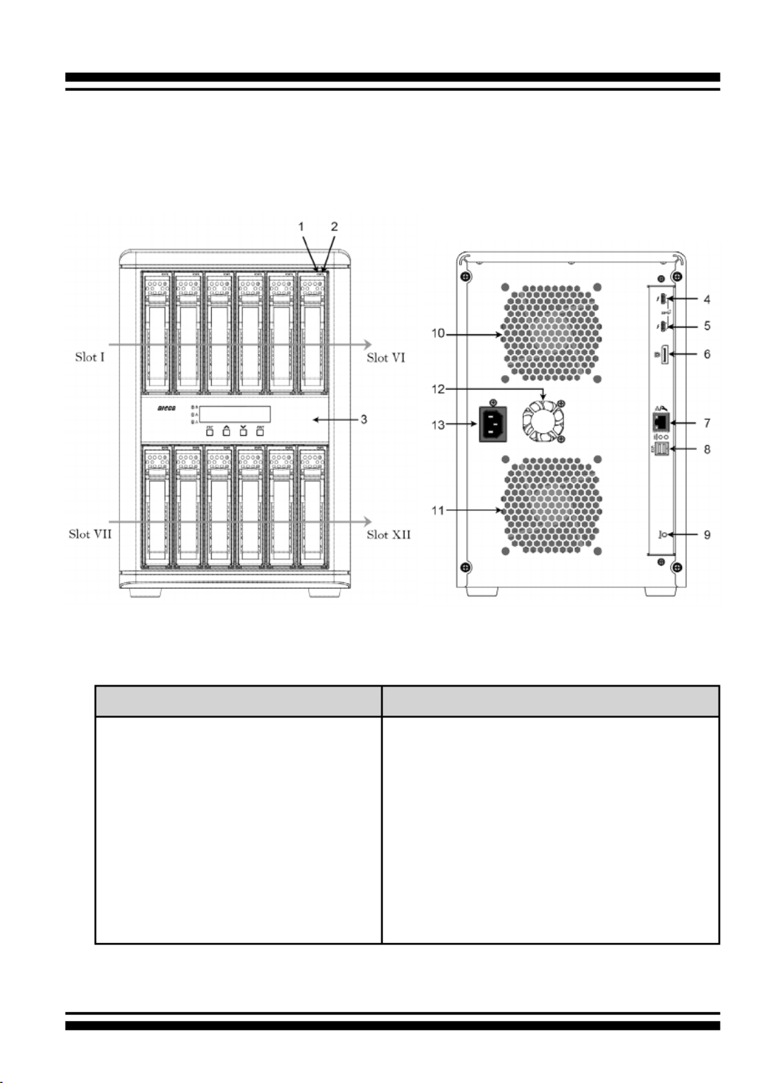
2.3 RAID Storage View
The following diagram is the ARC-8050T3U 4-bay RAID storage
front view and rear view.
Front View Rear View
1. Disk Activity LED
2. Disk Fault / Link LED
3. Power and Global Fault
LED
4. Thunderbolt & USB 3.2 Port1
5. Thunderbolt & USB 3.2 Port2
6. Display Port
7. Reset Button
8. LAN Port
9. Power Connector
10. System Fan
11. LCD Panel with Keypad

INSTALLATION
17
Front View Rear View
1. Disk Activity LED
2. Disk Fault / Link LED
3. LCD Panel with Keypad
4. Thunderbolt & USB 3.2 Port1
5. Thunderbolt & USB 3.2 Port2
6. Display Port
7. LAN Port
8. SAS Expansion Port
9. Reset Button
10. System Fan
11. Power Connector
The following diagram is the ARC-8050T3U 6-bay RAID storage
front view and rear view.

INSTALLATION
18
The following diagram is the ARC-8050T3U-6M RAID storage front
view and rear view.
Front View Rear View
1. Disk Activity LED
2. Disk Fault / Link LED
3. LCD Panel with Keypad
4. Thunderbolt & USB 3.2 Port1
5. Thunderbolt & USB 3.2 Port2
6. Display Port
7. LAN Port
8. SAS Expansion Port
9. Reset Button
10. System Fan
11. 4-Pin Male XLR (DC_IN)
12. Power Connector (AC_IN)

INSTALLATION
19
Front View Rear View
1. Disk Activity LED
2. Disk Fault/Link LED
3. LCD Panel with Keypad
4. Thunderbolt & USB 3.2 Port1
5. Thunderbolt & USB 3.2 Port2
6. Display Port
7. LAN Port
8. Reset Button
9. System Fan1
10. System Fan2
11. Power Connector
The following diagram is the ARC-8050T3U 8-bay RAID storage
front view and rear view.
INSTALLATION
20
Front View Rear View
1. Disk Activity LED
2. Disk Fault/Link LED
3. LCD Panel with Keypad
4. Thunderbolt & USB 3.2 Port1
5. Thunderbolt & USB 3.2 Port2
6. Display Port
7. LAN Port
8. SAS Expansion Port
9. Reset Button
10. System Fan1
11. System Fan2
12. Power Supply Fan
13. Power Connector
The following diagram is the ARC-8050T3U 12-bay RAID storage
front view and rear view.

INSTALLATION
21
• Disk Slot Numbers
To perform a disk hot-plug procedure, you must know the physical
disk slot number for the drive that you want to install or remove.
The number on the drive tray shows how RAID subsystem disk
slots are numbered. Disk slot number is reected in the RAID
manager interface. The sequence of disk slots goes from the top
of the enclosure to the bottom, from left to the right. (as shown
in storage front view gures)
• Drive Tray LED Indicators
Figure 2-1, Activity/Fault LED
(ARC-8050T3U-4/6/8/12)
Figure 2-2, Activity/Fault LED
(ARC-8050T3U-6M)
The following table describes the RAID storage disk drive tray LED
behavior.
Tray LED Normal Status Problem Indication
1. Activity LED
(Blue)
1. When the activity LED
is lit, there is I/O acti-
vity on that disk drive.
2. When the LED is not
lit; there is no activity
on that disk drive.
N/A
2. Fault/Link LED
(Red/Green)
1. When the fault LED is
lit, there is no disk
present.
2. When the link LED is
lit, there is a disk pre-
sent.
1. When the fault LED is off, the
disk is present and status is
normal.
2. When the fault LED is blinking
(2 times/sec.), the disk drive
has failed and should be hot-
swapped immediately.
3. When the activity LED is lit
and fault LED is fast blinking
(10 times/sec.) there is re-
building activity on that disk
drive.

INSTALLATION
22
• LCD Panel LED Indicators
There are a variety of status conditions that cause the RAID stor-
age panel monitoring LED to light. The front panel LCD comes
with three (3) status-indicating LEDs. The LEDs on the front
panel are dened, from top to bottom, Power, Busy, and Caution,
as shown in Figure 2-3.
Figure 2-3, LCD Panel LED
The following table provides a summary of the front panel LED.
Panel LED Normal Status Problem Indication
1. Power LED
(Green)
Solid green, when power on. Unlit, when power on.
2. Busy LED
(Amber)
Blinking amber during host ac-
cesses RAID storage.
Unlit or never icker.
3. Caution LED
(Red)
Unlit indicates that the RAID
storage and all its components
are operating correctly.
Solid indicates that one or
more component failure/Ur-
gent events have occurred.
• Rear View Function Description
Thunderbolt 3 Ports: Use the included Thunderbolt 3 cable to
connect to a Thunderbolt 3 port on your computer or other Thun-
derbolt 3 devices. Use the included USB Type-C cable on your
USB-only computer.
Display Port: DisplayPort 1.4 is a digital display interface used
to connect all displays with DisplayPort and Mini DisplayPort.
DisplayPort is backwards compatible with HDMI, DVI, and VGA
interfaces via an adapter (not included).

INSTALLATION
23
LAN Port: User can remote manage the RAID enclosure without
adding any user specic software (platform independent) via
standard web browsers directly connected to the 10/100Mbit
RJ45 LAN port.
SAS Expansion Port: The ARC-8050T3U-6/6M/12 contains one
expansion port that can connect up to 7 expander enclosures.
The maximum drive no. is 256 through this RAID storage with 7
expander enclosures.
Rest Button: Intelligent power On/Off function on storage turns
power in unison with the host computer power status. You can
press and hold the “Reset Button” for 3 seconds to force the RAID
storage power on or off in case you don’t connect the host.
Power Connector: Use this connector to connect the included
power cord.
XLR Connector: 4-pin XLR on the ARC-8050T3U-6M to accept
alternative power from a 4pin XLR power source
2.4 Setting Up RAID Storage
Setting up your ARC-8050T3U RAID storage involves these main
steps:
• Physically Install the RAID Storage and Drives
• Install the MRAID Software
• Congure RAID Volumes
• Format RAID Volumes
• Unmounting RAID Volumes
Details about these steps are described in the following sections.
2.4.1 Physically Install RAID Storage and Drives
Please follow the steps below in order they are given to ensure
that your ARC-8050T3U connected on your Thunderbolt computer.

INSTALLATION
24
Figure 2-4-1. Installing 2.5-inch
SAS/SATA Drive
Figure 2-4-2. Installing 3.5-inch
SAS/SATA Drive
Step 1. Install the Drives in the ARC-8050T3U Storage
Your RAID storage supports up to 4/6/8/12 x 3.5-inch disk drives
or 4/6/8/12 x 2.5-inch SAS or SATA 6.0Gb/s drives, each one
contained in its individual hole on the disk carrier. Each drive is
hot-pluggable, allowing you to remove and insert drives without
shutting down your RAID storage. Installation in this section
describes how to install or remove 3.5 inch drives in your RAID
storage.
1. Gently slide the drive tray out from the ARC-8050T3U RAID
storage.
2. Install the drive into the drive tray and secure the drive to the
drive tray by four of the mounting screws.
Figure 2-5, Sliding Drive Tray into Enclosure
3. After all drives are in the drive tray, slide all of them back into
the ARC-8050T3U RAID storage and make sure you latch the
drive trays.

INSTALLATION
25
Step 2. Connecting Thunderbolt 3 Ports on RAID Storage
Thunderbolt connectors are provided on the back of the ARC-
8050T3U RAID storage for connecting the array to Thunderbolt
host or USB host.
• Thunderbolt Computer Port Connection
There are two Thunderbolt connectors on the rear of ARC-
8050T3U RAID storage for connecting the array to Thunderbolt
host and next Thunderbolt devices. Connect ARC-8050T3U RAID
storage and Thunderbolt capable computer Thunderbolt port
with the Thunderbolt 3 icon using the included Thunderbolt 3
cable as shown below:
Figure 2-6, Connecting to Thunderbolt computer

INSTALLATION
26
Figure 2-7, Thunderbolt Computer Daisy Chain
Note:
Thunderbolt Daisy Chain Topologies
A single Thunderbolt technology daisy chain can have
seven devices, including the computer. Connect the cable
to one of the interface ports on the back of your ARC-
8050T3U RAID storage and to your Thunderbolt capable
computer. The additional port may be used to daisy chain
compatible computer peripherals, such as hard drives,
monitors, and much more.

INSTALLATION
27
Figure 2-8, Connecting to computer USB-C port with
the USB 3.2 Gen 1 or USB 3.2 Gen 2 icon
• USB-only Computer Port Connection
Your USB-only computer can recognize up to 1 volume when
connecting any Thunderbolt 3 port on the ARC-8050T3U.
Connect the cable to one of the Thunderbolt 3 ports on the
back of your ARC-8050T3U RAID storage and to your USB-only
capable computer. The additional port can’t support the daisy
chain function.
- Computer with a USB-C port
Connect ARC-8050T3U RAID storage and USB-only computer
USB-C port with the USB 3.2 Gen 1 or USB 3.2 Gen 2 icon
using the included USB-C cable as shown below:

INSTALLATION
28
- Computer with a USB 3.2 Gen 1 or USB 2.0 port (Type A)
Use the USB 3.2 (USB-C)–to–USB Type A cable for
compatibility with USB-only computers that do not have a
USB-C port. Connect ARC-8050T3U RAID storage and USB-
only computer USB X.X port with the USB 3.2 Gen 1 (USB 3.0)
or USB 2.0 icon using the optional USB 3.2 (USB-C) to USB
Type A cable as shown below:
Figure 2-9, Connecting to computer with a USB 3.2 Gen 1
or USB 2.0 port (Type A)
INSTALLATION
29
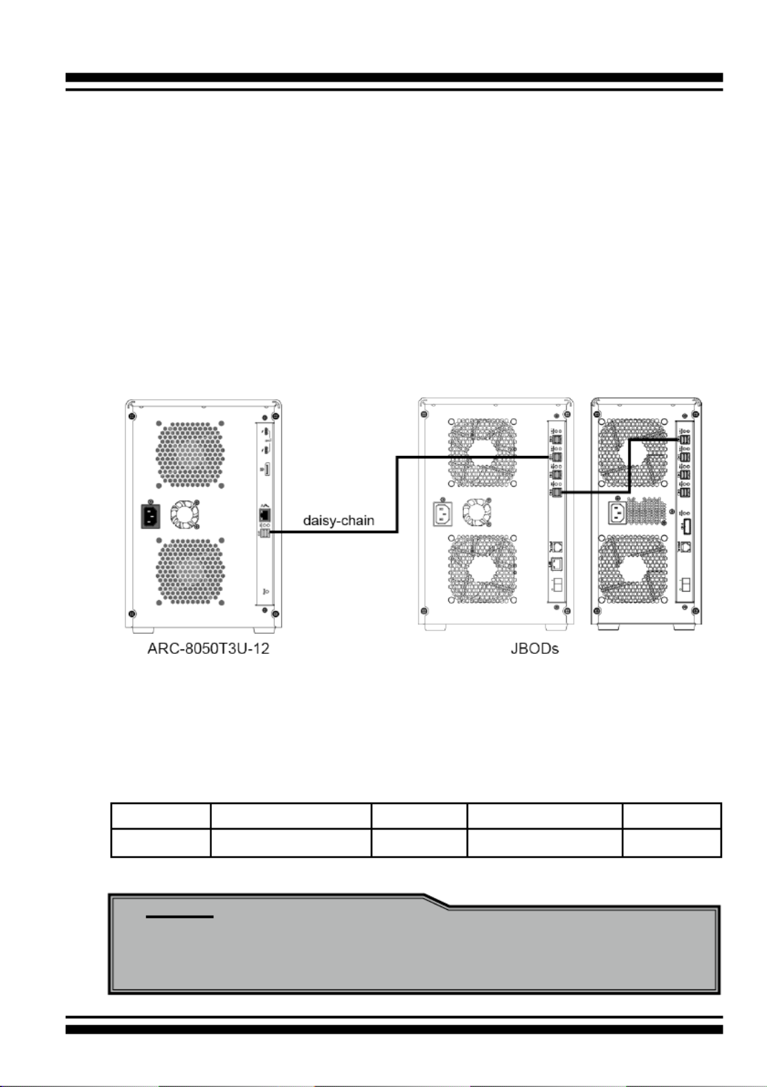
Step 3. Expansion Connection (Optional)
The ARC-8050T3U-6/12 12Gb/s SAS RAID storages contain one
expansion port that can connect up to 7 expander enclosures.
The maximum drive no. is 256 through this RAID storage with
7 expander enclosures. Enclosures installed with SAS disks or
SATA disks can be included in the same daisy-chain. The following
gure shows how to connect the external SFF-8644 cable from
the 12Gb/s SAS RAID storage to the external JBOD. Daisy-chains
longer than the limitation of storages are not supported even if it
may be workable.
Figure 2-10, Module Daisy-chain
The following table is the maximum number of ARC-8050T3U-6/12
RAID storage supported:
Disks/Enclosure Expander Disks/Controller Volume
Max No. 128 7 256 128
Note:
Turn on the JBOD rst to make sure the ARC-8050T3U-6/12
RAID storage recognizes the drives in the JBOD.

INSTALLATION
30
Step 4. Connecting Monitor Port (Optional)
You can connect LAN port to the manager clinet system, if you
want to congure and manage the RAID storage from the clinet
system through out-of-band manager.
• LAN Port Connection
User can remote manage the RAID enclosure without adding
any user specic software (platform independent) via standard
web browsers directly connected to the 10/100Mbit RJ45 LAN
port. Connect LAN port of the ARC-8050T3U using the included
Ethernet cable and then to a LAN port or LAN switch.
Step 5. Connecting RAID Storage Power
• To power the RAID storage:
1. Using the included power cord, connect this power cord to a
grounded electronical outlet and to the ARC-8050T3U RAID
storage.
2. ARC-8050T3U RAID storage will automatically turn on when
host computer power on status is received from the thun-
derbolt cable. It takes about 30 seconds to fully start up the
RAID storage.
Figure 2-11, Connecting the Power to Enclosure

INSTALLATION
31
3. ARC-8050T3U RAID storage automatically turns off when the
computer to which it is attached sleeps or is disconnected.
• To power the ARC-8050T3U-6M using 4-Pin XLR D.C.
Power Connections:
There is an industry standard 4-pin XLR on the ARC-8050T3U-
6M to accept alternative power from a 4pin XLR power source
(use battery power or supplied AC Adapter). There is no univer-
sal standard for this, however the most common convention for
DC power on ARC-8050T3U-6M XLR 4-pin connectors is:
pin 1 GND (0V)
pin 2 NC
pin 3 NC
pin 4 EXT DC (+11.5~15.5V)
The connector on ARC-8050T3U-6M is male. Check and double
check that the wiring is correct to your equipment before con-
necting DC power source to ARC-8050T3U-6M.
Note:
You can press and hold the “Reset” button for 3 seconds to
force the RAID storage power on or off.
When you are nished installing the ARC-8050T3U RAID storage,
you can set up the RAID volume using McRAID storage manager
or LCD to set up RAID volumes.

INSTALLATION
32
2.4.2 Mac Users
2.4.2.1 Install Areca driver for Mac
On November 10, 2020, Apple revealed new Mac hardware with
the revolutionary Apple Silicon M1 processors. Since external
boot via 3rd party drivers is not allowed on Apple Silicon based
Macs, the default Areca driver doesn’t work on new M1 Mac,
only for Intel-based Macs.
The macOS 11 had not been integrated any universal KEXTs into
macOS, which means that users need to install universal KEXT
to support Areca Thunderbolt devices on Apple Silicon. Areca
universal KEXT’s on Apple Silicon can be installed in /Library/
Extensions/, even if Areca RAID storage x86-only versions
persists on the system in /System/Library/Extensions/. In order
to use 3rd party kernel extensions on Apple Silicon Macs, users
must enable system extensions by changing their Mac’s Security
Policy to Reduced Security and allow user management of kernel
extensions from identied developers.
* If your mac version is below 11.0, you can skip this step
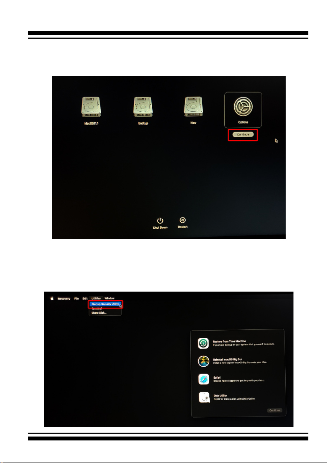
Step 1. Start up your computer in macOS Recovery
(1-1). Choose “Shut Down”.
(1-2). Press and hold the power button on your Mac until you
see “Loading startup options”.
INSTALLATION
33
(1-3). Click “ ”, then click “ ”. If requested, en-Options Continue
ter the password for an administrator account.
(1-4). In the Recovery app, choose > Utilities Startup Secu-
rity Utility.

INSTALLATION
34
(1-5). Select the system you want to use to set the security
policy and click “ ”. If the disk is encrypt-Security Policy
ed with FileVault, click Unlock, enter the password and
then click Unlock.
(1-6). Choose “ ” and enable “Allow user manReduced Security -
agement of kernel extensions from identied developers”.
(1-7). Click “ -OK” and conrm the action by entering your ad
ministrator credentials.
(1-8). Restart your Mac for the changes to take effect.

INSTALLATION
35
Step 2. Installing Areca driver
(2-1) Download the driver from Areca website: https://www..
areca.com.tw/support/downloads.html
(2-2) Double-click [ArcMSRu.pkg] in the mounted disk image to .
start.
Follow the installer on-screen steps to complete the installation.
(2-3) When Areca installation shows successful, system will pop .
the following “System Extension Updated” warning mes-
sage: A program tried to load new system extension(s)
signed by “ Areca Technology corporation” but your se-
curity setting do not allow system extensions. To enable
them, choose the “ ” to allow Open Security Preferences
system extension.

INSTALLATION
36
(2-5) On Security & Privacy’s General page.
• Make sure the message “System software from developer
“Areca Technology Corporation” was blocked from loading.”
• Make the setting to allow loading the driver. To unlock a
preference pane, click the key icon at the lower left of the
“Security & Privacy” screen. You are prompted to enter the
password for the administrator account. Enter the informa-
tion for “ ” and “ ,” then click “User Name Password OK”.
(2-6) Make sure “Areca Technology Corporation” is displayed as .
the developer and click “Allow”.
* This message about being blocked is only displayed for only 30
minutes after installing the driver. When 30 minutes have passed
after installing, the message is no longer displayed.
* In the following condition, no message is displayed. Loading of
the driver is permitted.

INSTALLATION
37
• When a driver that has previously been allowed is reinstalled
again.
• When you’re using a Mac on which the driver was installed before
now updating to macOS 11
A message prompting you to restart appears. Click “Restart”.
This completes installation of the driver.
INSTALLATION
38
2.4.2.2 Install the MRAID Utility
This section describes detailed instructions for installing the
Areca Mac utility on your Apple Thunderbolt capable machine.
You must have administrative level permissions to install macOS
utility. This can be done in just a few steps!
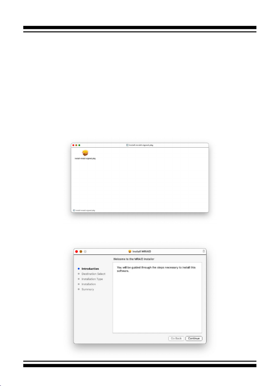
1. Download the install-mraid installer from the website at
“ ”, the https://www.areca.com.tw/support/downloads.html
le name begins with “install-mraid” followed by the version
control.
2. Navigate to your Downloads folder and double-click the
install-mraid software. The Installer will open.
3. Click on the " " button to begin the installation. Continue

INSTALLATION
39
4. If you have no need to change the install location or select to
install special components, you can skip the step 4-1 and
step 4-2, just click on the " " button to continue the Install
standard (default) installation procedure.
4-1. Click on the " " button to select Change Install Location
the disk where you want to install the MRAID software.

INSTALLATION
40
• MRAID is included below two applications for the
ARC-8050T3U RAID storage.
- ArcHTTP has to be installed for GUI RAID console (McRAID
storage manager) to run. It also runs as a service or
daemon in the background that allows capturing of
events for mail and SNMP traps notication. Refer to
the chapter 3 ArcHTTP Conguration on ARC-8050T3U
user manual, for details about the mail and SNMP traps
conguration.
- provides the functionality CLI (Command Line Interface)
available in MRAID storage manager through a Command
Line Interface. You can set up and manage RAID storage
inline. CLI performs many tasks at the command line. You
can download CLI manual from Areca website.
4-2, Click on the " " button to choose special Customize
components. Click on an icon to install special
components and click the “Install” button to continue.

INSTALLATION
41
• ArcHTTP64 is required for ArcHTTP runing as a service or
daemon, and have it automatically start the proxy for all
controllers found.
5. Enter your system password and click the “ ” Install Software
button.
6. The system will need to be restarted when the installation is
complete. Click “ ” button.Continue Installation

INSTALLATION
42
7. A program bar appears that measures the progress of the
driver installation.
8. When this screen shows, you have completed the installation
and click on the " " button to reboot your computer Restart
in order to complete installation.

INSTALLATION
43
9. There is a MRAID folder icon showing on your desktop. The
folder contains two items (ArcCLI64 and ArcHTTP64) that are
for you to launch the MRAID storage manager.
If you have not yet installed the hardware, please follow the
“2.4.1 Physically Install RAID Storage and Drives” section
to install it. Otherwise, to begin the creation volume, go on
the“2.4.2.3 Congure RAID Volumes” section to congure the
volume.
2.4.2.3 Congure RAID Volumes
There are often multiple ways to accomplish the same congura-
tion and maintenance tasks for your RAID storage. Your ARC-
8050T3U RAID storage can be congured by one of the following
methods:
1. McRAID Storage Manager from ArcHTTP. (Thunderbolt port)
2. McRAID Storage Manager Through LAN port.
3. LCD Panel with Keypad.
• Method 1: McRAID Storage Manager From ArcHTTP
Start McRAID Storage Manager – Browser Edition
There is one “ ” icon showing on your desktop. Double-MRAID
click on the “ ” icon to locate your ArcHTTP utility and MRAID
CLI program le folder.
INSTALLATION
44
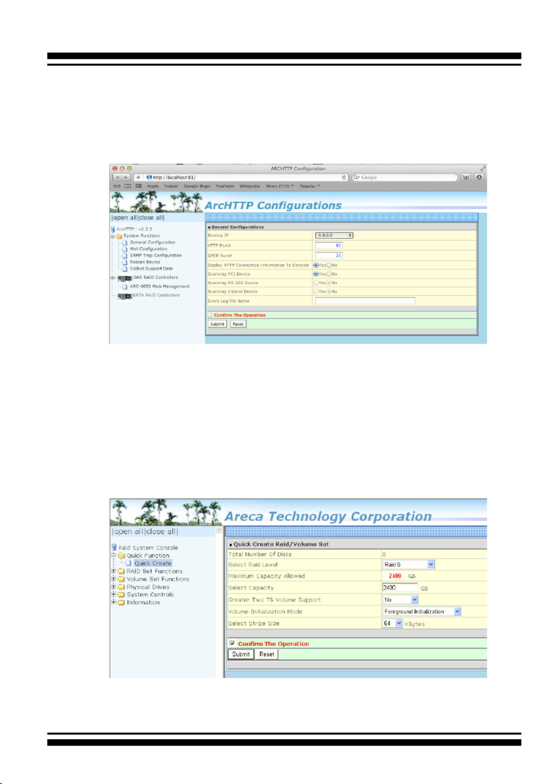
When you double-click on the “ ”, it shows all RAID ArcHTTP64
storages available on the system and create an individual
RAID storage icon located on left column of the “ArcHTTP Con-
gurations” screen.
Locate “ARC-8050T3U Web Management” and launch the
selected McRAID storage manager. Enter RAID storage default
User Name “admin” and the Password “ ” when the login 0000
page prompted for it. After logging in, the McRAID storage
manager process starts.

INSTALLATION
45
Click on the “Quick Create” in the main menu, your volume is
automatically congured based on the number of disks in your
system. You can create a RAID set associated with exactly one
volume set. The user can change the Raid Level, Capacity,
Initialization Mode, and Stripe Size. A hot spare option is also
created, depending on the exist conguration. Tick on the
“Conrm The Operation” check box and click on the “Submit”
button, the RAID set and volume set will start to initialize. If
you prefer to customize your volume set, please use the “Raid
Set Functions” and “Volume Set Functions”. See chapter 4 of
ARC-8050T3U user manual for information on customizing
your RAID volumes using McRAID storage manager. Other-
wise, to begin using the ARC-8050T3U right away, go on the
next “Format the Volume” section to begin the formatting
procedure.
• Method 2: McRAID Storage Manager Through LAN port
User can remote manage the RAID storage directly connected
to the 10/100Mbits RJ45 LAN port via standard web browsers.
To congure ARC-8050T3U RAID storage using a LAN port,
you need to know its IP address. The default IP address will
be shown on the LCD initial screen. Launch your web browser-
based McRAID storage manager by entering http://[IP Ad-
dress] in the web browser. Enter RAID storage default User
Name “ ” and the Password “ ” when the login page admin 0000
prompted for it. After logging in, the McRAID storage man-
ager process starts. Follow the on-screen steps, responding as
needed, to congure RAID volume. See the Chapter 4 of ARC-
8050T3U user manual for information on customizing your
RAID volumes using McRAID storage manager.
• Method 3: LCD Panel with Keypad
You can use LCD front panel and keypad function to simply
create the RAID volume. The LCD status panel also informs
you of the disk array’s current operating status at a glance.
The LCD conguration is described in a separate manual:
ARC-8050T3_LCD manual. You can download ARC-1009 (LCD
Manual) from Areca website. The LCD provides a system
of screens with areas for information, status indication, or
menus. The LCD screen displays up to two lines at a time of
menu items or other information. ARC-8050T3U RAID storage
default User Name is “admin” and the Password is “0000”.

INSTALLATION
46
2.4.2.4 Format and Partition RAID Volumes
After the volume set is ready for system accesses, it needs to be
partitioned, formatted, and mounted by the operating system.
When you create a volume through McRAID storage manager,
the macOS recognizes that a new disk is avail, and displays a
message asking what you next want to do. If the message does
not show up, start the “Disk Utility” manually from the “Finder”,
use the “Go” menu and open the “Utilities” folder. Double-click
on the “Disk Utility” program.
To format and partition your unit
1. Formatting a drive in Disk Utility is easy, though Disk Utility
uses a different term: Erase. When the Disk Utility window
opens, nd and select the desired drive in the sidebar that
represents your RAID storage. This is how you prepare to
erase and format the RAID storage.
The LCD initial screen is shown below:
INSTALLATION
47
Choose OS X Extended (Journaled) for the Format, and,
for the Scheme, choose GUID Partition Map. You could also
choose MS-DOS as the format, if you want to be able to use
the drive on both a Mac and a PC. In that case, choose Mas-
ter Boot Record for the Scheme. Click “ ” button in the Erase
toolbar, and Disk Utility will erase and format the RAID stor-
age. When it is complete, icons for this partition shows up on
your desktop. It is now ready to use.
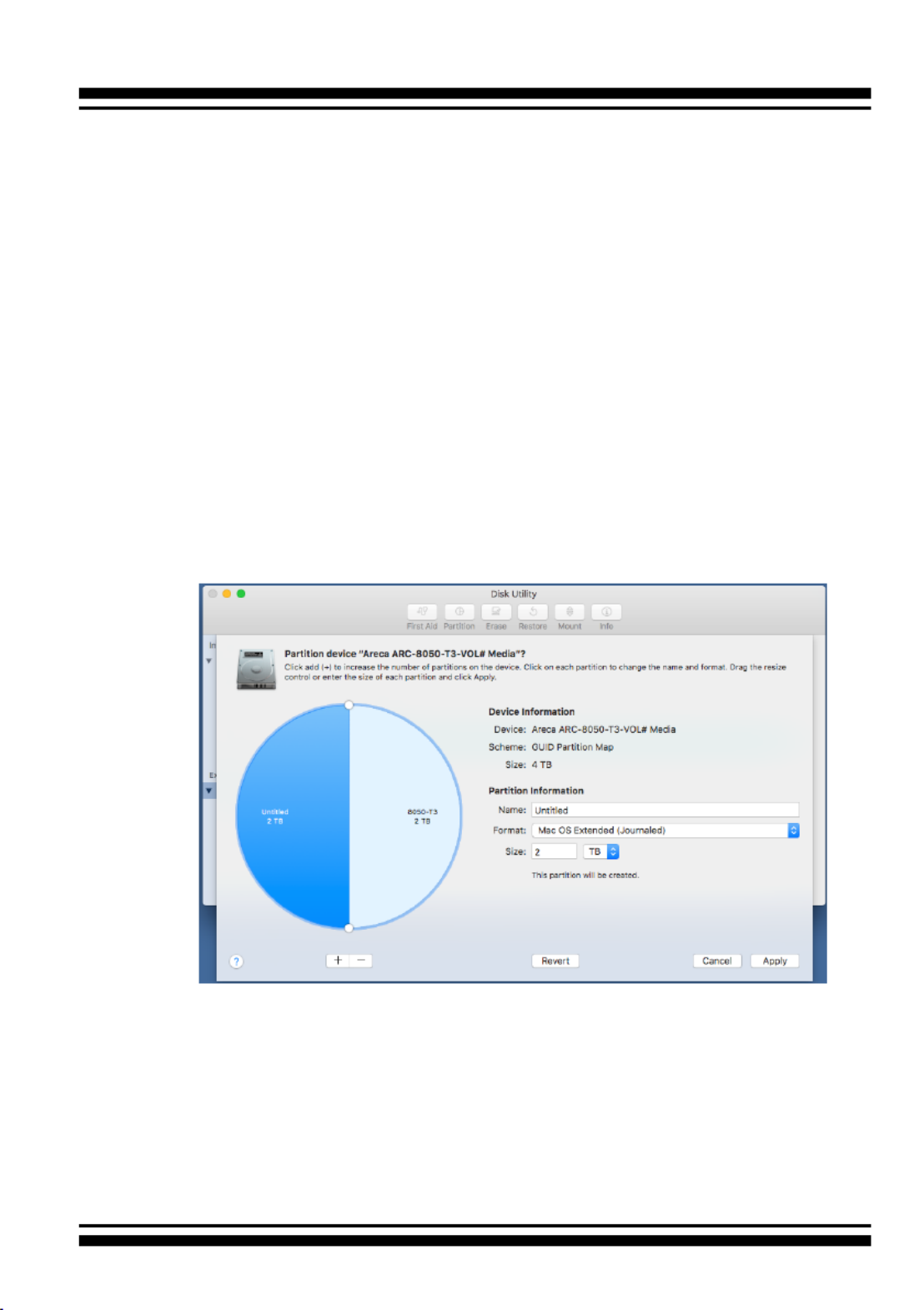
2. You may want to divide a drive into more than one partition.
When you do this, each partition is a volume, and each vol-
ume shows up as a separate drive on your Desktop. To parti-
tion a drive, select it in Disk Utility, and then click “Partition”
in the toolbar. Disk Utility shows the RAID storage’s space as
a pie chart. By default, RAID storage only contain a single
partition, but to add one, click the + icon; you’ll see two par-
titions.
If you want to adjust their sizes, you can do so by dragging
the circles dividing the partitions, or by typing a size into the
Size eld. When you click “ ”, Disk Utility erases the Apply
RAID storage and splits it into the number of partitions you
have selected. Each partition will appear as a separate drive
on your Desktop.

INSTALLATION
48
When a message asks you to conrm you want to partition
the disk, click on the “ ” button. This may take a Partition
couple of minutes, depending on the size of the drives in your
RAID storage. When the partitioning is complete, icons for
each new partition show up on your desktop. They are now
ready to use.
2.4.2.5 Make A Bootable RAID Volume
You can follow the following procedures to add ARC-8050T3U
RAID volume on Intel-based Mac bootable device listing.
1. Set the BIOS selection in System Controls: Advance Congu-
ration to “UEFI” option for Intel-based Mac boot.
2. Download macOS Sierra and follow the https://support.apple.
com/en-us/HT202796 link “How to set up and use an external
Mac startup disk”.
3. Mac doesn’t see devices that have Option ROM rmware until
you load the rmware by pressing “Option-Shift-Command-
Period” at the Startup Manager window.
4. Do this each time you want to start up from ARC-8050T3U.
2.4.2.6 Unmounting RAID Volumes
To avoid possible data corruption, Areca recommends that ARC-
8050T3U RAID storages volume(s) be properly unmounted from
the computer prior to turning off the RAID storage or safely
removing the Thunderbolt interface cable.
1. Drag RAID storage volume(s) icon to the trash. The Trash will
turn into an Eject arrow. This will assure that all data is
properly cleared from the system memory before the volume
is removed.
2. When the volume icon disappears from the desktop, RAID
storage can be disconnected from the computer.

INSTALLATION
49
INSTALLATION
50
2.4.3 Windows Users
2.4.3.1 Install the Thunderbolt Software
This section describes how to install the Thunderbolt software to
your operating system. The software installation includes device
driver, ArcHTTP and CLI utility.
In this scenario, you are installing the Thunderbolt software in
an existing Windows system. You can use the installer to install
driver, ArcHTTP and CLI at once or “Custom” to install special
components. Follow the steps below to install the driver & utility
for Windows.
1. Download the install_thunderbolt installer from the website
at " ", the https://www.areca.com.tw/support/downloads.html
le name begins with “install_thunderbolt” followed by the
version control.
2. Double-click on the zipped le that comes from the website
to unzip it. Double-click on the "setup.exe" le for installing
thunderbolt software.
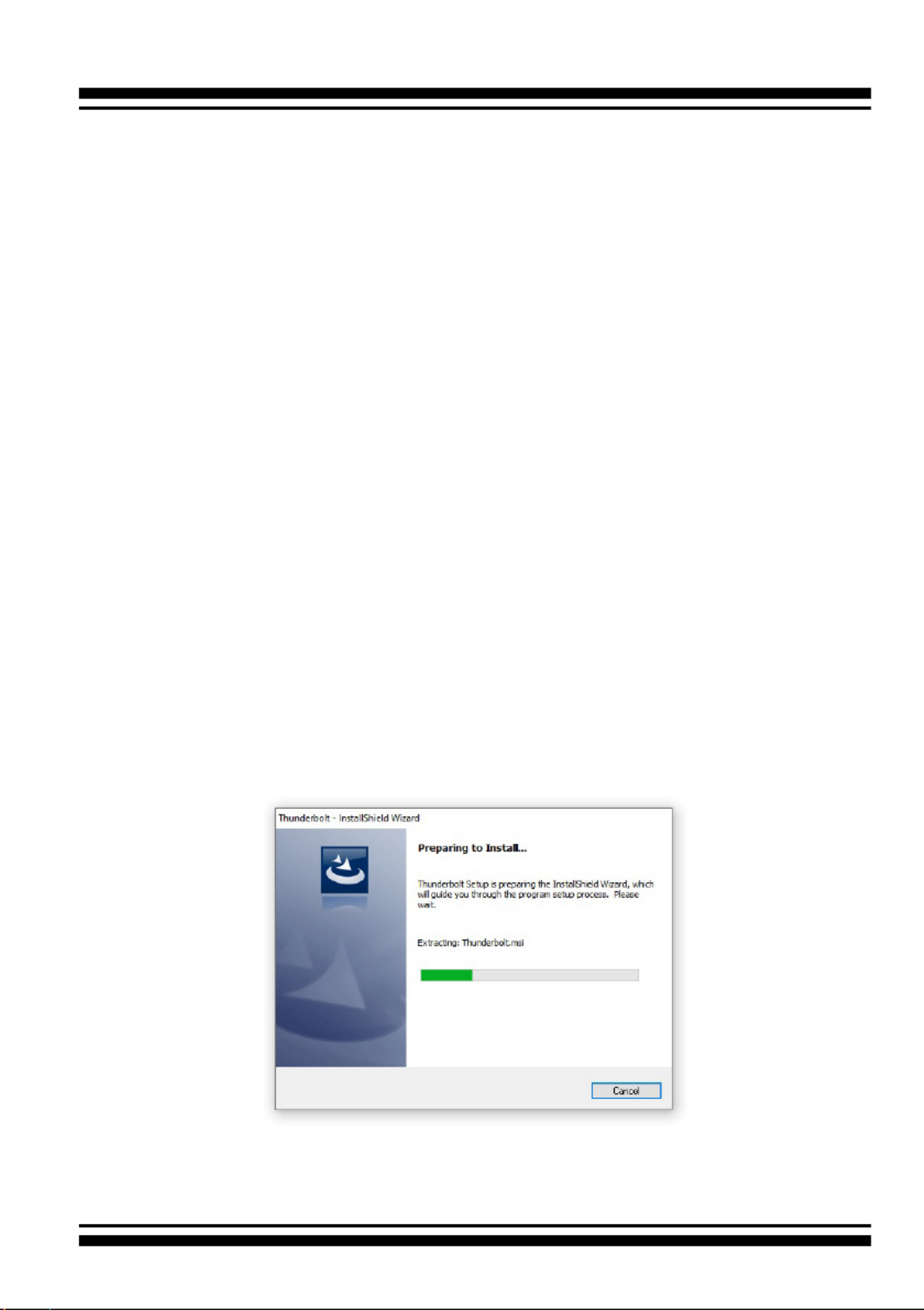
3. The screen shows Preparing to Install.
4. The Thunderbolt Installer (or InstallShield Wizard) opens, pre-
paring to install and click on the “ ” button to continue.Next

INSTALLATION
51
5. When the License Agreement screen appears, read and agree
to the license information; then let the InstallShield Wizard
guide you through the installation process.
6. On the Setup Type screen, use the settings to specify these
things: and click on the “ ” button to continue.Next
INSTALLATION
52
• “Complete” to install driver, ArcHTTP and CLI utility at once,
check the rst box.
• “Custom” to install special components and change the pro-
gram directory. When this “ ” check box is checked, go Custom
to the Custom Setup screen.
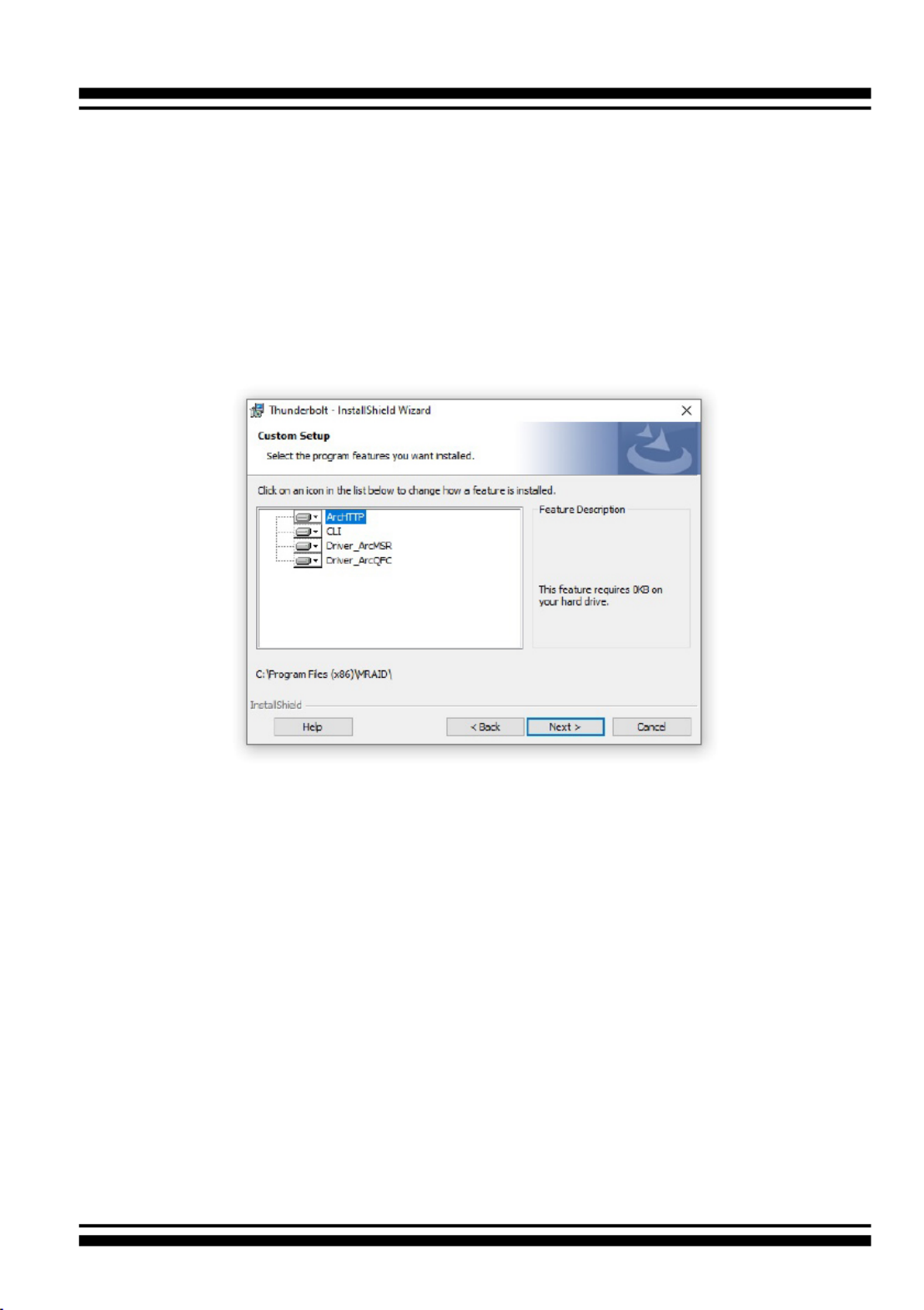
6-1. On the Custom Setup screen, click on an icon to install
special components and click on the “ ” button to Next
continue.
• Driver is required for the operating system to be able to inter-
act with the ARC-8050T3U RAID storage.
• has to be installed for GUI RAID console (McRAID ArcHTTP
storage manager) to run. It also runs as a service or daemon
in the background that allows capturing of events for mail and
SNMP traps notication. Refer to the chapter 3 ArcHTTP Con-
guration on ARC-8050T3U user manual, for details about the
mail and SNMP traps conguration.
• CLI (Command Line Interface) provides the functionality
available in MRAID storage manager through a Command Line
Interface. You can set up and manage RAID storage inline. CLI
performs many tasks at the command line. You can download
CLI manual from Areca website.

INSTALLATION
53
7. When you reach the installation page, click on the “ ” Install
button to continue.
8. A program bar appears that measures the progress of the
driver installation.
When this screen completes, you have completed the MRAID
installation. If you have no ARC-8050T3U RAID storage unit yet
connected or powered on, a “MRAID Installer Information”
message displays.
9. After installation is complete, click on the “ ” button to Finish
exit the InstallShield Wizard.

INSTALLATION
54
Note:
“For Windows, Install Driver First”
For Windows PC: the Thunderbolt certied device driver
must be installed before plugging in the device for it to
function properly.
10. The ArcHTTP and CLI are installed at the same time on ARC-
8050T3. Once ArcHTTP and CLI have been installed, the Arc-
HTTP background task automatically starts each time when
you start your computer. There is one MRAID icon showing
on your “Programs” folder. This icon is for you to start up
the McRAID storage manager (by ArcHTTP) and CLI utility. If
you have not yet installed the hardware, please follow the
“2.4.1 Physically Install RAID Storage and Drives” section to
install it. Otherwise, to begin the creation volume, go on the
“2.4.3.2 Congure RAID Volumes” section to congure the
volume.
2.4.3.2 Congure RAID Volumes
There are often multiple ways to accomplish the same congura-
tion and maintenance tasks for your RAID storage. Your ARC-
8050T3U RAID storage can be congured by one of the following
methods:
1. McRAID Storage Manager from ArcHTTP. (Thunderbolt port)
2. McRAID Storage Manager Through LAN port.
3. LCD Panel with Keypad.

INSTALLATION
55
• Method 1: McRAID Storage Manager From ArcHTTP
Start McRAID Storage Manager – Browser Edition
The “ ” icon shows on the button of ArcHTTP Taskbar
system tray by default. Double click “ArcHTTP Taskbar” to
launch the ArcHTTP Conguration screen. It automatically
scans the localhost RAID units on the system and creates an
individual RAID storage icon located in the left column screen.
When you double click on a selected element the left col-
umn screen, child element belonged parent element appears.
Locate “ARC-8050T3U Web Management” and launch the
McRAID storage manager.
Locate “ARC-8050T3U Web Management” and launch the
selected McRAID storage manager. Enter RAID storage default
User Name “admin” and the Password “ ” when the login 0000
page prompted for it. After logging in, the McRAID storage
manager process starts.

INSTALLATION
56
Click on the “Quick Create” in the main menu, your volume is
automatically congured based on the number of disks in your
system. You can create a RAID set associated with exactly one
volume set. The user can change the Raid Level, Capacity,
Initialization Mode, and Stripe Size. A hot spare option is also
created, depending on the exist conguration. Tick on the
“Conrm The Operation” check box and click on the “Submit”
button, the RAID set and volume set will start to initialize. If
you prefer to customize your volume set, please use the “Raid
Set Functions” and “Volume Set Functions”. See chapter 4 of
ARC-8050T3U user manual for information on customizing
your RAID volumes using McRAID storage manager. Other-
wise, to begin using the ARC-8050T3U right away, go on the
next “Format the Volume” section to begin the formatting
procedure.
• Method 2: McRAID Storage Manager Through LAN port
User can remote manage the RAID storage directly connected
to the 10/100Mbits RJ45 LAN port via standard web browsers.
To congure ARC-8050T3U RAID storage using a LAN port,
you need to know its IP address. The default IP address will
be shown on the LCD initial screen. Launch your web browser-
based McRAID storage manager by entering http://[IP Ad-
dress] in the web browser. Enter RAID storage default User
Name “ ” and the Password “ ” when the login page admin 0000
prompted for it. After logging in, the McRAID storage man-
ager process starts. Follow the on-screen steps, responding as
needed, to congure RAID volume. See the Chapter 4 of ARC-
8050T3U user manual for information on customizing your
RAID volumes using McRAID storage manager.
• Method 3: LCD Panel with Keypad
You can use LCD front panel and keypad function to simply
create the RAID volume. The LCD status panel also informs
you of the disk array’s current operating status at a glance.
The LCD conguration is described in a separate manual:
ARC-8050T3_LCD manual. You can download ARC-1009 (LCD
Manual) from Areca website. The LCD provides a system
of screens with areas for information, status indication, or
menus. The LCD screen displays up to two lines at a time of
menu items or other information. ARC-8050T3U RAID storage
default User Name is “admin” and the Password is “0000”.

INSTALLATION
57
The LCD initial screen is shown below:
2.4.3.3 Format RAID Volumes
After the volume set is ready for system accesses, it needs to be
partitioned, formatted, and mounted by the operating system.
The following steps show how to make any new disk arrays or
independent disks accessible to Windows system.
1. Click “Start” ==> right-click “Computer” and select “Manage”.
2. Click “Disk Management” in the left pane.
3. Scroll down to the bottom of the middle pane. Windows will
display a list of new drives attached to your system with a
label such as “Disk 1” or “Disk 2”, etc.
4. Right-click on the drive you want to partition and then again
to format it.
5. Once it’s formatted, Windows automatically assigns the next
available drive letter to it and then it will appear in Windows
Explorer.
2.4.3.4 Unmounting RAID Volumes
To avoid possible data corruption, Areca recommends that ARC-
8050T3U RAID storages volume(s) be properly unmounted from
the computer prior to turning off the RAID storage or safely
removing the Thunderbolt interface cable.

INSTALLATION
58
Note:
You can also safely remove devices from the computer folder.
Click the "Start" button, click "Computer", right-click the
device you want to remove, and then click "Eject".
2. Windows will display a notication telling you it's safe to
remove the Thunderbolt storage volume. Now you can unplug
.the Thunderbolt cable
To unmount ARC-8050T3U RAID storage from a Windows
system:
1. Click on the "Safely Remove Hardware and Eject Media" icon
in the notication area, at the lower right-hand side of your
screen, and then, in the list of devices, choose the Thunder-
bolt storage volume option that you want to remove.

ArcHTTP Conguration
59
3. ArcHTTP Conguration
This chapter describes how to congure the “System Function” of
ArcHTTP. The ArcHTTP proxy utility runs as a service or daemon, and
has it automatically start the proxy for all RAID storages found. This
way the RAID storage can be managed remotely without having to
sign in the server.
Start ArcHTTP– Browser Edition:
1. In Windows, right-click on “Start” menu and choose “Programs”.
Clicking “MRAID” program icon starts the ArcHTTP utility
(From the Start menu, choose Programs > MRAID > ArcHTTP).
2. On a Mac, there is one MARID icon showing on your desktop.
This icon is for you to start up the ArcHTTP utility.
When you click the ArcHTTP, it shows all RAID storages available on
the system and “System Function” on left column of the “ArcHTTP
Congurations” screen. The ArcHTTP has also integrated the email
notication and SNMP function for user to send SNMP traps and e-mail
notications. ArcHTTP conguration setting will store on a le name
“ArcHTTPSrv.conf”.
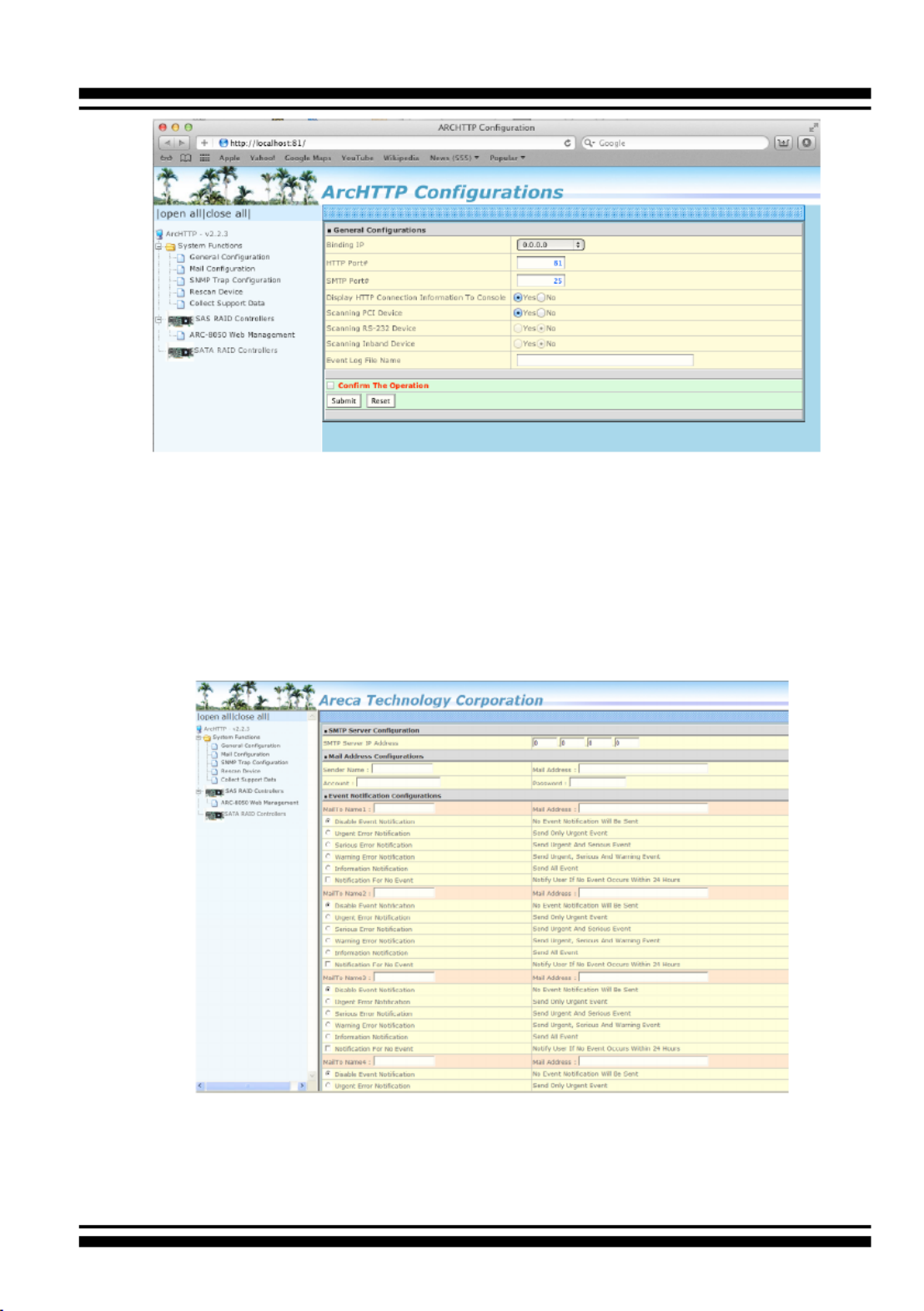
• General Conguration
Binding IP: Restrict ArcHTTP proxy server to bind only single
interface (If more than one physical network in the server).
HTTP Port#: Value 1~65535.
Display HTTP Connection Information To Console: Select “Yes" to
show Http send bytes and receive bytes information in the console.
Scanning PCI Device: Select “Yes” for ARC-8050T3U RAID storage
unit.
Scanning RS-232 Device: No.
Scanning Inband Device: No.
ArcHTTP Conguration
60
• Mail (Alert by Mail) Conguration
Many users require that email notications be sent to the
appropriate administrators when an alert is detected. To set up your
mail servers, click on the the “Mail Conguration” link. The “SMTP
Server Congurations” allows you to dene settings for your mail
server. This setup screen is shown as below:
1. SMTP Server Conguration
SMTP Server IP Address: Enter the SMTP server IP address which
is not McRAID storage manager IP.
Ex: 192.168.0.2.

ArcHTTP Conguration
61
2. Mail Address Congurations
Sender Name: Enter the sender name that will be shown in the
outgoing mail.
Ex: RaidController_1.
Mail address: Enter the sender email that will be shown in the
outgoing mail, but don’t type IP to replace domain name.
Ex: RaidController_1@areca.com.tw.
Account: Enter the valid account if your SMTP mail server
requires authentication.
Password: Enter the valid password if your SMTP mail server
requires authentication.
3. Event Notication Congurations
This step involves setting up of notication rules. Notication
rules instruct ArcHTTP on the notications that should be sent
when certain types of alerts are detected.
MailTo Name: Enter the alert receiver name that will be shown in
the outgoing mail.
Mail Address: Enter the receiver's e-mail address. This is the
address you want the e-mail alerts sent to.
Ex: admin@areca.com.tw.
According to your requirement, set the corresponding event level:
Disable Event Notication: No event notication will be sent.
Urgent Error Notication: Send only urgent events.
Serious Error Notication: Send urgent and serious events.
Warning Error Notication: Send urgent, serious and warning
events.
Information Notication: Send all events.
Notication For No Event: Notify user if no event occurs within 24
hours.
• SNMP Traps Conguration
To enable the RAID storage to send the SNMP traps to client SNMP
manager using the IP address assigned to the operating system,
such as Net-SNMP manager, you can simply use the SNMP function
on the ArcHTTP proxy server software. To enable the RAID storage
SNMP traps sending function, click on the “SNMP Conguration” link.
The ArcHTTP proxy only provide one direction to send the trap to
the SNMP manager without needing to install the SNMP extension
ArcHTTP Conguration
62
agent on the host. If SNMP manager requests to query the SNMP
information from RAID storage, please refer the Appendix C "SNMP
Operation & Installation". The “SNMP traps Conguration” menu will
show as following:
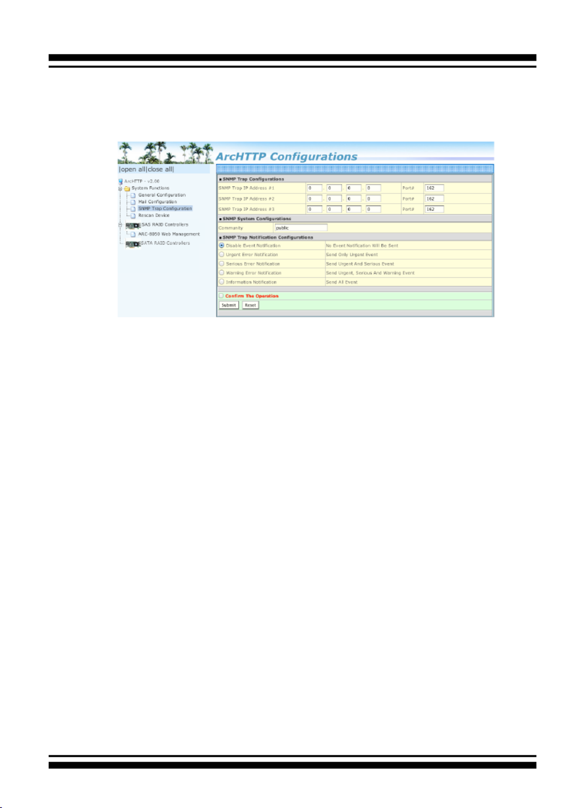
When you open the SNMP traps conguration page, you will see the
following settings:
1. SNMP Trap Congurations
Enter the SNMP trap IP address.
2. SNMP System Congurations
Community name acts as a password to screen accesses to the
SNMP agent of a particular network device. Type the community
names of the SNMP agent in this eld. Before access is granted
to a request station, this station must incorporate a valid
community name into its request; otherwise, the SNMP agent will
deny access to the system. Most network devices use “public” as
default of their community names. This value is case-sensitive.
3. SNMP Trap Notication Congurations
Before the client side SNMP manager application accepts the
RAID storage traps, it is necessary to integrate the MIB into the
management application’s database of events and status indicator
codes. This process is known as compiling the MIB into the
application. This process is highly vendor-specic and should be
well-covered in the User’s Guide of your SNMP application. Ensure
the compilation process successfully integrates the contents of
the areca_sas.mib le into the traps database. Please refer to Ap-
pendix C of “SNMP Operation & Installation”. The MIBs le resides
at: <CD-ROM>\packages\SNMP_MIBs on the software CD.

ArcHTTP Conguration
63
• Rescan Device Conguration
Let’s assume you’ve put all Areca RAID storages to a system. The
ArcHTTP scans the RAID storages on the system and create an
individual RAID storage icon located on left column of the "ArcHTTP
Congurations" screen. This adapter icon is for user to launch web
browser RAID manager. If there is any RAID storage missed on the
system start-up, you can use the "Rescan Device" function. The
"Rescan Device" function is a procedure which forces the ArcHTTP to
rescan the targets to allow a missed RAID storage to be added.
• Collect Support Data
Areca has added the “Collect Support Data” option on the ArcHTTP
utility to download a support le (le name:ctlrxx-xxxxx.log) with
all necessary information (system information, conguration, disk
information, eventlog). The “Collect Support Data” function will be
automatically started when ERROR or SERIOUS event occurred.”
Note:
Event Notication Table refer to Appendix D.
After you conrm and submit congurations, you can use
"Generate Test Event" feature to make sure these settings are
correct.

WEB BROWSER-BASED CONFIGURATION
64
4. Web Browser-based Conguration
If you need to use a RAID volume from ARC-8050T3U RAID storage
unit, you must rst create a RAID volume by using LCD or McRAID
storage manager. This chapter shows you how to set up RAID volumes
using the McRAID storage manager application on a computer with an
ARC-8050T3U RAID storage.
The McRAID storage manager is rmware-based utility, which is acces-
sible via the web browser installed on your operating system. The web
browser-based McRAID storage manager is a HTML-based application,
which utilizes the browser (Safari, IE and Mozilla etc) installed on your
monitor station. It can be accessed through the in-band Thunderbolt
bus or out-of-band onboard LAN port. The in-band-Thunderbolt bus
method can launch the web browser-based McRAID storage manager
via ArcHTTP proxy server.
The rmware-embedded web browser-based McRAID storage manager
allows local or remote to access it from any standard internet browser.
The rmware-embedded SMTP manager monitors all system events
and user can select either single or multiple user notications to be
sent with “Plain English” e-mails. The rmware-embedded SNMP agent
allows remote to monitor events with no SNMP agent required. the Use
McRAID storage manager to:
• Create RAID set
• Expand RAID set
• Dene volume set
• Add physical drive
• Modify volume set
• Modify RAID level/stripe size
• Dene pass-through disk drives
• Modify system function
• Update rmware
• Designate drives as hot spares

65
WEB BROWSER-BASED CONFIGURATION
4.1 Start-up McRAID Storage Manager
With McRAID Storage Manager, you can:
• Locally manage a system containing a supported RAID storage
that has Windows or macOS, ArcHTTP and a supported
browser.
• Remote and managed systems must have a TCP/IP connection.
• McRAID Storage Manager from Local Administration
(In-Band)
Once ArcHTTP and CLI have been installed, the ArcHTTP - back
ground task automatically starts each time when you start your
computer. There is one MARID icon showing on Mac “Desktop”
or one “ ” icon showing on Windows ArcHTTP Taskbar
system tray. This icon is for you to start up the ArcHTTP (launch
the McRAID storage manager). When you click on the
ArcHTTP64 from MRAID or “ ” from system ArcHTTP Taskbar
tray, it shows all RAID controllers available on the host system
and create an individual RAID controller icon located on left
column of the “ArcHTTP Congurations” screen. This RAID con-
troller icon is for user to launch the selected RAID controller
web browser McRAID storage manager.
The “Enter Network Password” dialog screen appears, type the
User Name and Password. The RAID controller default User
Name is “admin” and the Password is “0000”. After entering
the user name and password, press key to access the Enter
McRAID storage manager.

WEB BROWSER-BASED CONFIGURATION
66
• McRAID Storage Manager Through LAN Port
(Out-of-Band)
ARC-8050T3U RAID storage also offers an alternative out-of-
band method for McRAID storage manager. User can access the
built-in conguration without running the ArcHTTP proxy server
on the host system. The web browser-based McRAID storage
manager is a HTML-based application, which utilizes the brows-
er installed on your remote system. To ensure proper commu-
nications between the Thunderbolt RAID storage and McRAID
storage manager, please connect the Thunderbolt RAID storage
LAN port to any LAN switch port.
The RAID storage has embedded the TCP/IP & web browser-
based McRAID storage manager in the rmware. User can re-
mote manage the Thunderbolt RAID storage without adding any
user specic software (platform independent) via standard web
browsers directly connected to the 10/100Mbit RJ45 LAN port.
To congure Thunderbolt RAID storage on a remote machine,
you need to know its IP address. The IP address is default
shown on the LCD initial start-up screen. Launch your McRAID
storage manager by entering http://[IP Address] in the web
browser.
4.2 McRAID Main Window
The following login screen is displayed in the browser. This screen
displays the initial start-up conguration.
The RaidSet Hierarchy displays the “Raid Set List”, “Volume Set
List”, and “Physical Disk List”. The RAID set information, volume
set information, and drive information can also be viewed by
clicking on the “RAID Set Hierarchy”on the main menu screen.

67
WEB BROWSER-BASED CONFIGURATION
• To display RAID set information, move the mouse cursor to the
desired RAID set number, then click on it. The RAID set infor-
mation will be displayed.
• To display volume set information, move the mouse cursor to
the desired volume set number, then click it. The volume set
information will be displayed.
• To display drive information, move the mouse cursor to the
desired physical drive number, then click it. The drive informa-
tion will be displayed.
4.3 Main Menu
The main menu shows all available functions, accessible by clicking
on the appropriate link.
Individual Category Description
Quick Function Create a default conguration, which is based on the
number of physical disks installed; it can modify the
volume set Capacity, Raid Level, and Stripe Size.
Raid Set Functions Create a customized RAID set.
Volume Set Functions Create customized volume sets and modify the ex-
isted volume sets parameter.
Physical Drives Create pass through disks and modify the existing
pass through drives parameters. Also provides the
function to identify disk drives (blinking fault LED).
System Controls Setting the RAID system conguration.
Information Viewing the controller information. The Raid Set Hier-
archy can be viewed through the “Raid Set Hierarchy”
item.
4.4 Quick Function
The Quick Create option congures the arrays with just a few
steps. Although srives of different sizes may be used in the array,
Quick Create will only operate upon drives of the same physical
size.
The number of physical drives in the RAID storage determines the
Raid Levels that can be implemented with the RAID set. You can
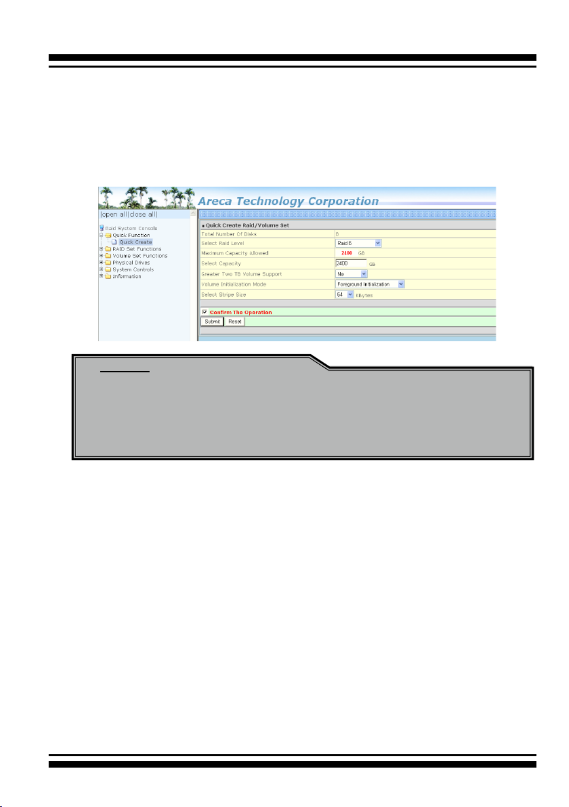
WEB BROWSER-BASED CONFIGURATION
68
create a RAID set associated with exactly one volume set. The user
can change the Raid Level, Capacity, Initialization Mode, and Stripe
Size. A hot spare option is also created, depending on the exist
conguration. Tick on the “Conrm The Operation” check box and
click on the “Submit” button in the “Quick Create” screen, the RAID
set and volume set will start to initialize.
4.5 Raid Set Functions
Use the “Raid Set Function” and “Volume Set Function” if you prefer
to customize your volume set. Manual conguration can provide full
control of the RAID set settings, but it will take longer to complete
than the “Quick Volume/Raid Setup” conguration. Select the “Raid
Set Function” to manually congure the RAID set for the rst time
or delete and recongure existing RAID sets. (A RAID set is a group
of disks containing one or more volume sets.)
4.5.1 Create Raid Set
To create a RAID set, click on the “Create Raid Set” link. A “Select
The Drive For Raid Set” screen is displayed showing the drive(s)
connected to the current controller and enclosures. Click on the
selected physical drives within the current RAID set. Enter 1 to 15
Note:
In “Quick Create”, your volume set is automatically congured
based on the number of disks in your system. Use the “Raid
Set Functions” and “Volume Set Functions” if you prefer to
customize your volume set, or RAID 30/50/60 volume set.

69
WEB BROWSER-BASED CONFIGURATION
Note:
To create RAID 30/50/60 volume, you need create multiple
RAID sets rstly with the same disk numbers on each RAID
set.
alphanumeric characters to dene a unique identier for a RAID
set. The default RAID set name will always appear as “Raid Set
#”.
Tick on the “Conrm The Operation” check box and click on the
“Submit” button on the screen; the RAID set will start to initialize.
If you have available disk member, you can repeat above proce-
dures to dene another RAID sets. The “Max 128 volumes” is the
default mode for SAS RAID storage. The “Max 16 volumes” mode
is used for support roaming this raidset to Areca SATA RAID con-
trollers. The SATA RAID controller is designed to support up to 16
volumes only. You have to use “Max 16 volumes” on the raidset
mode if you plan to roam this raidset between SAS RAID control-
ler and SATA RAID controller.
4.5.2 Delete Raid Set
To delete a RAID set, click on the “Deleted Raid Set” link. A
“Select The Raid Set To Delete” screen is displayed showing all
exist RAID sets in the current controller. Click the RAID set num-
ber which you want to delete in the select column on the delete
screen. Then, tick on the “Conrm The Operation” check box and
click on the “Submit” button in the screen to delete it. The volume
sets included in the “Delete RAID Set”. It will be deleted by this
action. But for the Raid 30/50/60, you need to delete the volumes
belonging to those RAID sets.

71
WEB BROWSER-BASED CONFIGURATION
Note:
1. Once the “Expand Raid Set” process has started, user can
not stop it. The process must be completed.
2. If a disk drive fails during RAID set expansion and a hot
spare is available, an auto rebuild operation will occur
after the RAID set expansion completes.
3. RAID 30/50/60 does not support the "Expand Raid set".
4. RAID set expansion is a quite critical process, we strongly
recommend customer backup data before expand. Unex-
pected accident may cause serious data corruption.
4.5.4 Ofine Raid Set
This function is for customer being able to unmount and remount
a multi-disk volume. All Hdds of the selected RAID set will be put
into ofine state, spun down and fault LED in fast blinking mode.
User can remove those Hdds and insert new Hdds on those empty
slots without needing power down the controller to perform the
online array roaming.
4.5.5 Rename Raid Set
The default RAID set name will always appear as “Raid Set #”
when it is rst created by the controller. The "Rename Raid Set"
function is for customer to rename the default RAID set name.
To rename a RAID set from a group of RAID sets:
1. Click on the ”Rename Raid Set" link.
2. Click the RAID set check box from the list that you wish to re-
name. Click the “Submit” button. The following screen appears.
Use this option to rename the RAID set name.

WEB BROWSER-BASED CONFIGURATION
72
4.5.6 Activate Incomplete Raid Set
If one of the disk drives is removed in power off state, the RAID
set state will change to “Incomplete State”. If the user wants to
continue to operate the controller without power-off the RAID
storage, the user can use the “Activate Incomplete Raid Set” op-
tion to active the RAID set. After the user completes this function,
the Raid State will change to “Degraded Mode” and start to work.
To activate the incomplete the RAID set, click on the “Activate
Raid Set” link. A “Select The Raid Set To Activate” screen is dis-
played showing all RAID sets existing on the current controller.
Click the RAID set number to activate in the select column. Click
on the “Submit” button on the screen to activate the RAID set
that had a disk removed (or failed) in the power off state. The
RAID storage will continue to work in degraded mode.
4.5.7 Create Hot Spare
When you choose the “Create Hot Spare” option in the “Raid Set
Function”, all unused physical devices connected to the current
controller appear. Select the target disk by clicking on the ap-
propriate check box. Tick on the “Conrm The Operation” check
box and click the “Submit” button in the screen to create the hot
spares.

73
WEB BROWSER-BASED CONFIGURATION
The “Create Hot Spare” gives you the ability to dene a global or
dedicated hot spare. Firmware default (“Global For SSD or HDD”)
only uses SSD to rebuild SSD array or HDD to rebuild HDD array.
If you want rebuild a SSD array with a HDD, please congure the
HDD as hotspare disk for both HDD and SSD (“Global For All”) to
activate the rebuilding of the new array. “Dedicated to RaidSet”
and “Dedicated to Enclosure” can only be used with a specic
RAID set or Enclosure. When a disk drive fails in the RAID set or
enclosure with a dedicated hot spare is pre-set, data on the disk
drive is rebuild automatically on the dedicated hot spare disk.
4.5.8 Delete Hot Spare
Select the target hot spare disk to delete by clicking on the ap-
propriate check box. Tick on the “Conrm The Operation” check
box and click the “Submit” button on the screen to delete the hot
spares.
4.5.9 Rescue Raid Set
When the system is powered off in the RAID set update/creation
period, the conguration possibly could disappear due to this
abnormal condition. The “RESCUE” function can recover the miss-
ing RAID set information. The RAID storage uses the time as the
RAID set signature. The RAID set may have different time after
the RAID set is recovered. The “SIGANT” function can regenerate
the signature for the RAID set.

WEB BROWSER-BASED CONFIGURATION
74
Caution:
Please contact us to make sure if you need to use rescue
function. Improperly usage may cause conguration
corruption.

75
WEB BROWSER-BASED CONFIGURATION
4.6 Volume Set Functions
A volume set is seen by the host system as a single logical device.
It is organized in a RAID level with one or more physical disks.
RAID level refers to the level of data performance and protection of
a volume set. A volume set capacity can consume all or a portion
of the disk capacity available in a RAID set. Multiple volume sets
can exist on a group of disks in a RAID set. Additional volume sets
created in a specied RAID set will reside on all the physical disks
in the RAID set. Thus each volume set on the RAID set will have its
data spread evenly across all the disks in the RAID set.
The following is the volume set features for the RAID storage.
1. Volume sets of different RAID levels may coexist on the same
RAID set and up to 128 volume sets per controller.
2. Up to 128 volume sets can be created in a RAID set.
3. The maximum addressable size of a single volume set is not lim-
ited to 2TB, because the controller is capable of 64-bit LBA
mode. However the operating system itself may not be capable
of addressing more than 2TB.
See Areca website ftp://ftp.areca.com.tw/RaidCards/Docu-
ments/Manual_Spec/ Over2TB_050721.ZIP le for details.
4.6.1 Create Volume Set (0/1/10/3/5/6)
To create volume set from RAID set storage, move the cursor bar
to the main menu and click on the “Create Volume Set” link. The
“Select The Raid Set To Create On It” screen will show all RAID
set number. Tick on a RAID set number that you want to create
and then click on the “Submit” button.
The new create volume set attribute allows user to select the
Volume Name, RAID Level, Capacity, Greater Two TB Volume
Support, Initialization Mode, Strip Size, Cache Mode, Tagged
Command Queuing, and SCSI Channel/SCSI ID/SCSI Lun.

WEB BROWSER-BASED CONFIGURATION
76
• Volume Name
The default volume name will always appear as “ARC-8050T3U-
VOL”. You can rename the volume set providing it does not
exceed the 15 characters limit.
• Volume Raid Level
Set the Raid Level for the volume set. Highlight the desired
RAID Level from the available RAID levels option.
There are two circumstances when you choose RAID level 1
function:
RAID 1-Simple Mirroring is also known as “ ”; two disk mirror
If your RAID set has two disks, data written on one disk drive is
simultaneously written to another disk drive.
RAID 1-Multi Mirroring is also known as “ ”; If triple disk mirror
your RAID set has three disks, data written on one disk drive is
simultaneously written to another two disk drives.
• Capacity
The maximum volume size is the default initial setting. Enter
the appropriate volume size to t your application.
• Greater Two TB Volume Support
Controller uses the "Greater Two TB Volume Support" sub-menu
to set the volume capacity and sector size. Greater Two TB
Volume Support option: "No", "64bit LBA" and "Use 4K Block".

77
WEB BROWSER-BASED CONFIGURATION
-No
When this option is enabled, it keeps the volume size with
max. 2TB limitation. For any hard disk drives working in the
4K native mode in the Raid set, the volume set directly sets
and exposes 4KB sector size to the operating system.
-64bit LBA
This option uses 16 bytes CDB instead of 10 bytes. The maxi-
mum volume capacity is up to 512TB. For any hard disk drives
working in the 4K native mode in the Raid set, the volume
set directly sets and exposes 4KB sector size to the operating
system. This option works on different OS which supports 16
bytes CDB.
-Use 4K Block
This option uses 16 bytes CDB and changes the sector size
from default 512 bytes to 4k bytes. Windows XP only supports
maximum volume capacity is up to 16TB.
• Initialization Mode
This option is used to dene “Background Initialization”, “Fore-
ground Initialization” or “No Init (To Rescue Volume)”. When
“Background Initialization”, the initialization proceeds as a
background task, the volume set is fully accessible for system
reads and writes. The operating system can instantly access to
the newly created arrays without requiring a reboot and waiting
the initialization complete. When “Foreground Initialization”, the
initialization proceeds must be completed before the volume set
ready for system accesses. There is no initialization happened
when you select “No Init” option. “No Init“ is for customer to
rescue volume without losing data in the disk.
• Stripe Size
This parameter sets the size of the stripe written to each disk
in a RAID 0, 1, 10, 5, 6, 50 or 60 logical drive. You can set the
stripe size to 4 KB, 8 KB, 16 KB, 32 KB, 64 KB, 128 KB, 256 KB,
512KB or 1M. A larger stripe size produces better read per-
formance, especially if your computer does mostly sequential
reads. However, if you are sure that your computer does ran-
dom reads more often, select a smaller stripe size.

WEB BROWSER-BASED CONFIGURATION
78
• Cache Mode
The RAID storage supports “Write Through” and “Write Back”
cache.
• Volume Write Protection
When "Volume Write Protection" is enabled on the "Modify
Volume Set", host commands fail if they are issued to a volume
in that RAID controller and attempt to modify a volume's data
or attributes. Volume Write Protection is used primarily for
customer-initiated disaster recovery testing.
• Full Volume Encryption
ARC-8050T3U have featured with controller based hardware
encryption function. Controller based hardware encryption de-
scribes the encryption of data occurring at the disk array con-
troller before being sent to the disk drives. Since RAID control-
ler is a natural central point of all data therefore encryption at
this level is inherent and also reduces deployment complexity.
ARC-8050T3U RAID controller has dedicated electronic circuitry
for the cryptographic engine embedded in the ROC and operat-
ing at full channel speeds. The hardware encryption does not
impact the performance of ARC-8050T3U RAID controller and
can implement on any kinds of HDD that is transparent to the
user, the OS, and applications.
Encrypting your volume can give your data an extra layer of
protection be yond setting up a controller password. Encryption
will conceal your volume’s data and make accessing the les
almost im possible for anyone who does not know your encryp-
tion key. Data saved in the volume will be hidden by Algorithm
developed by Areca Technology. With this scramble process, no
one can see and access into the hidden volume data without
access key. ARC-8050T3U support 128- and 256-bit encryp-
tion keys using AES(a key size of 128, or 256 bits), or pass-
word (a variable key size). Each encryption key size causes
Note:
• RAID level 3 can’t modify the cache stripe size.
• Roaming the stripe size 256K/512K/1M Raid Set to rmware
version older than 1.52 will cause data corruption.

79
WEB BROWSER-BASED CONFIGURATION
the algorithm to behave slightly differently, so the increasing
key sizes not only offer a larger number of bits with which you
can scramble the data, but also increase the complexity of the
cipher algorithm. ARC-1882 adapters provide ve new key
options in the Full Volume Encryption:“Disable”, “256Bit key,
Password”, “256Bit key, AES”, “128Bit key, Password”, “128Bit
key, AES”. You can generate the new key by CLI utility or API
code function.
This volume encryption function can only work with ARC-1882
series with any kinds of HDD. You can follow below steps to en-
able the function.
1. Create volume set with “Full Volume Encryption” capability in
the web management.
2. Use CLI “vsf genkey” command or API code to generate key
le.
3. Use “Download Volume Key File” in the web management or
use CLI “vsf dlkey” command to download volume key le
into rmware and unlock the volume.
4. Follow step 3. to unlock volume if volume locked.
• Tagged Command Queuing
The “Enabled” option is useful for enhancing overall system
performance under multi-tasking operating systems. The
Command Tag (Drive Channel) function controls the SAS
command tag queuing support for each drive channel. This
function should normally remain “Enabled”. “Disabled” this
function only when using SAS drives that do not support
command tag queuing.
• SCSI Channel/SCSI ID/SCSI Lun
SCSI Channel: The RAID storage function is simulated as an
external SCSI RAID controller. The host bus is represented as a
SCSI channel. Choose the SCSI Channel.
SCSI ID: Each SCSI device attached to the SCSI card, as well
as the card itself, must be assigned a unique SCSI ID number.
A SCSI channel can connect up to 15 devices. The RAID storage
is a large SCSI device. Assign an ID from a list of SCSI IDs.
SCSI LUN: Each SCSI ID can support up to 8 LUNs. Most 6Gb/s
SAS controllers treat each LUN like a SAS disk.

81
WEB BROWSER-BASED CONFIGURATION
Click a volume set number and the “Conrm The Operation”
check box and then click the “Submit” button to delete the vol-
ume set.
4.6.4 Modify Volume Set
To modify a volume set from a RAID set:
1. Click on the “Modify Volume Set” link.
2. Click the volume set check box from the list that you wish to
modify.
Click the “Submit” button. The following screen appears.
Use this option to modify the volume set conguration. To modify
volume set attributes, move the cursor bar to the volume set at-
tribute menu and click it. The “Enter The Volume Attribute” screen
appears. Move the cursor to an attribute item and then click the
attribute to modify the value. After you complete the modica-
tion, tick on the “Conrm The Operation” check box and click the
“Submit” button to complete the action. The user can only modify
the last volume set capacity.

WEB BROWSER-BASED CONFIGURATION
82
4.6.4.1 Volume Growth
Use “Expand Raid Set" function to add disk to a RAID set. The
additional capacity can be used to enlarge the last volume set
size or to create another volume set. The “Modify Volume Set”
function can support the “Volume Modication” function. To
expand the last volume set capacity, move the cursor bar to
the “Capacity” item and entry the capacity size. When nished
the above action, click on the "Submit" button to complete the
action. The last volume set starts to expand its capacity.
To expand an existing volume noticed:
• Only the last volume can expand capacity.
• When expand volume capacity, you can’t modify stripe size or
modify RAID level simultaneously.
• You can expand volume capacity, but can’t reduce volume
capacity size.
• After volume expansion, the volume capacity can't be
decreased.
For greater 2TB expansion:
• If your system installed in the volume, don't expand the
volume capacity greater 2TB, except your OS and controller
can support boot up from a greater 2TB capacity device.
• Expand over 2TB used LBA64 mode. Please make sure your
OS supports LBA64 before expand it.
4.6.4.2 Volume Set Migration
Migrating occurs when a volume set is migrating from one RAID
level to another, when a volume set strip size changes, or when
a disk is added to a RAID set. Migration state is displayed in the
volume state area of the “RAID Set Hierachy” screen.
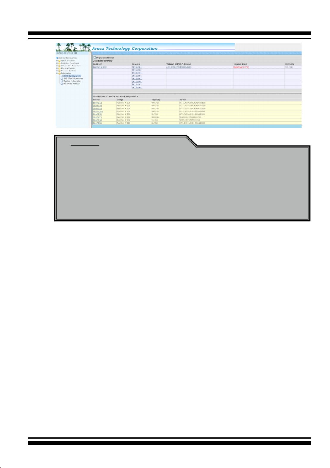
83
WEB BROWSER-BASED CONFIGURATION
Note:
1. If the volume is RAID level 30, 50, or 60, you can not
change the volume to another RAID level. If the volume
is RAID level 0, 1, 10(1E), 3, 5, or 6, you can not change
the volume to RAID level 30, 50, or 60.
2. Power failure may damage the migration data. Please
backup the RAID data before you start the migration
function.
4.6.4.3 Volume Write Protection
When "Volume Write Protection" is enabled on the "Modify
Volume Set", host commands fail if they are issued to a volume
in that RAID controller and attempt to modify a volume's data
or attributes. Volume Write Protection is used primarily for
customer-initiated disaster recovery testing.
4.6.5 Check Volume Set
To check a volume set from a RAID set:
1. Click on the “Check Volume Set” link.
2. Click on the volume set from the list that you wish to check.
Tick on “Conrm The Operation” and click on the “Submit” button.
Use this option to verify the correctness of the redundant data in
a volume set. For example, in a system with dedicated parity, vol-
ume set check means computing the parity of the data disk drives
and comparing the results to the contents of the dedicated parity
disk drive. The checking percentage can also be viewed by click-
ing on “RAID Set Hierarchy” in the main menu.
Specyfikacje produktu
| Marka: | Areca |
| Kategoria: | serwer |
| Model: | ARC-8050T3U-4 |
Potrzebujesz pomocy?
Jeśli potrzebujesz pomocy z Areca ARC-8050T3U-4, zadaj pytanie poniżej, a inni użytkownicy Ci odpowiedzą
Instrukcje serwer Areca

29 Września 2024
29 Września 2024
29 Września 2024
28 Września 2024
28 Września 2024
Instrukcje serwer
- serwer Sony
- serwer Supermicro
- serwer Lenovo
- serwer Gigabyte
- serwer Acer
- serwer Technics
- serwer Hikvision
- serwer Fujitsu
- serwer Conceptronic
- serwer StarTech.com
- serwer Asus
- serwer Medion
- serwer TRENDnet
- serwer MSI
- serwer Toshiba
- serwer D-Link
- serwer ATen
- serwer APC
- serwer HP
- serwer Tripp Lite
- serwer Cisco
- serwer Moxa
- serwer Synology
- serwer Lindy
- serwer ZyXEL
- serwer Dell
- serwer Linksys
- serwer Digitus
- serwer Vimar
- serwer Netgear
- serwer Black Box
- serwer ELAC
- serwer Intellinet
- serwer HGST
- serwer Revox
- serwer Naim
- serwer SEH
- serwer Planet
- serwer NEC
- serwer LevelOne
- serwer Digi
- serwer Axis
- serwer Asrock
- serwer Abus
- serwer Rocstor
- serwer Western Digital
- serwer Smart-AVI
- serwer Promise Technology
- serwer QNAP
- serwer Chenbro Micom
- serwer Allnet
- serwer Veritas
- serwer IStarUSA
- serwer Silverstone
- serwer Ernitec
- serwer AVerMedia
- serwer Atlona
- serwer Gefen
- serwer Hanwha
- serwer Quantum
- serwer Blackmagic Design
- serwer Kathrein
- serwer Eaton
- serwer Monacor
- serwer Sonnet
- serwer In Win
- serwer Teo
- serwer Megasat
- serwer Kramer
- serwer KanexPro
- serwer Raritan
- serwer AMX
- serwer C2G
- serwer Acti
- serwer Sitecom
- serwer Maxdata
- serwer Matrox
- serwer Flir
- serwer Buffalo
- serwer GeoVision
- serwer LaCie
- serwer Valcom
- serwer Asustor
- serwer Intel
- serwer Fantec
- serwer Freecom
- serwer Seagate
- serwer Iomega
- serwer Luxman
- serwer Ibm
- serwer Provision ISR
- serwer TAIDEN
- serwer SIIG
- serwer Advantech
- serwer Extron
- serwer Avocent
- serwer Teradek
- serwer Silex
- serwer Sun
- serwer MvixUSA
- serwer Dual Bay
- serwer Raidsonic
- serwer EMC
- serwer Infortrend
- serwer Opengear
- serwer G-Technology
- serwer EXSYS
- serwer Middle Atlantic
- serwer Mr. Signal
- serwer Atlantis Land
- serwer Lantronix
- serwer NETSCOUT
- serwer Mobotix
- serwer Origin Storage
Najnowsze instrukcje dla serwer
9 Kwietnia 2025
2 Kwietnia 2025

2 Kwietnia 2025
2 Kwietnia 2025
28 Marca 2025
28 Marca 2025
28 Marca 2025

10 Marca 2025
10 Marca 2025
10 Marca 2025