Instrukcja obsługi Tripp Lite PDUMVR30HVNET
Tripp Lite
Listwa zasilająca
PDUMVR30HVNET
Przeczytaj poniżej 📖 instrukcję obsługi w języku polskim dla Tripp Lite PDUMVR30HVNET (36 stron) w kategorii Listwa zasilająca. Ta instrukcja była pomocna dla 4 osób i została oceniona przez 2 użytkowników na średnio 4.5 gwiazdek
Strona 1/36

1
Owner’s Manual
Single-Phase 0U Switched
Power Distribution Units with
Individual Outlet Current Metering
PDUMVR20NET • PDUMVR30NET • PDUMVR30HVNET
(AG-0044) (AG-0045) (AG-0046)
Important Safety Instructions 2
Installation 3
Digital Load Meter 8
Features 8
Configuration and Operation 11
Service 11
Warranty and Product Registration 12
Español 13
Français 25
1111 W. 35th Street, Chicago, IL 60609 USA • www.tripplite.com/support
Copyright © 2016 Tripp Lite. All rights reserved.
PROTECT YOUR INVESTMENT!
Register your product for quicker service
and ultimate peace of mind.
You could also win an
ISOBAR6ULTRA surge protector—
a $100 value!
www.tripplite.com/warranty
16-10-211-933668.indb 1 12/22/2016 11:36:07 AM

2
Important Safety Instructions
SAVE THESE INSTRUCTIONS
This manual contains instructions and warnings that should be followed during
the installation, operation, and storage of this product. Failure to heed these
instructions and warnings may affect the product warranty.
• The PDU provides the convenience of multiple outlets, but DOES NOT provide surge or line
noise protection for connected equipment.
• The PDU is designed for indoor use only, in a controlled environment, away from excess
moisture, temperature extremes, conductive contaminants, dust or direct sunlight.
• Keep indoor ambient temperature between 32°F and 122°F (0°C and 50°C).
• The PDU must be installed by a qualified technician only.
• Do not attempt to mount the PDU to an insecure or unstable surface.
• Install in accordance with National Electrical Code standards. Be sure to use the proper
overcurrent protection for the installation, in accordance with the plug/equipment rating.
• Connect the PDU to an outlet that is in accordance with your local building codes and that is
adequately protected against excess currents, short circuits and earth faults.
• The electrical outlets supplying power to the equipment should be installed near the equipment
and easily accessible.
• Do not connect the PDU to an ungrounded outlet or to extension cords or adapters that
eliminate the connection to ground.
• Be sure to provide a local disconnect device on any models that are permanently installed
without a plug that is easily accessible.
• Never attempt to install electrical equipment during a thunderstorm.
• Individual equipment connected to the PDU should not draw more current than the individual
PDU’s outlet’s rating.
• The total load connected to the PDU must not exceed the maximum load rating for the PDU.
• Do not attempt to modify the PDU, input plugs or power cables.
• Do not drill into or attempt to open any part of the PDU housing. There are no user-serviceable
parts inside.
• Do not attempt to use the PDU if any part of it becomes damaged.
• Use of this equipment in life support applications where failure of this equipment can
reasonably be expected to cause the failure of the life support equipment or to significantly
affect its safety or effectiveness is not recommended.
16-10-211-933668.indb 2 12/22/2016 11:36:07 AM

1-2
1-1
1-3 1-4
3
Installation
Mounting the PDU
Note: The illustrations may differ somewhat from your PDU model. Regardless of configuration, the user must
determine the fitness of hardware and procedures before mounting. The PDU and included hardware are designed
for common rack and rack enclosure types and may not be appropriate for all applications. Exact mounting
configurations may vary. Screws for attaching the mounting brackets and cord retention shelf to the PDU are
included. Use only the screws supplied by the manufacturer, or their exact equivalent.
If installing the PDU in a rack that has button-mount slots, you only need to perform steps for
toolless mounting (step 1-1 ). If your rack does not have button-mount slots, proceed to step
1-2.
Toolless Mounting
1-1 Attach the included mounting buttons
to the PDU. Position the PDU as desired
in the rack enclosure, align the buttons
with the rack mounting slots, and slide
the PDU into position.
Note: To install the PDU with its outlets
facing the rear of the rack, use the included
PDUMVROTATEBRKT accessory. This V-shaped
bracket provides a mounting button on one leg
of the V and a button-mount slot on the other,
effectively repositioning the mounting buttons.
See Features section for image.
Regular Mounting
1-2 Attach the mounting brackets to the
PDU.
1-3 Attach the cord retention (Optional)
bracket(s) to the PDU.
1-4 Attach the PDU to a vertical rail in your
rack or rack enclosure. Use the included
mounting hardware to attach the
mounting brackets to the rail.
PDUMVR30HVNET Shown
16-10-211-933668.indb 3 12/22/2016 11:36:12 AM

A
4
Connecting the PDU
2-1 Connect the input plug to your facility’s
compatible AC power source.
2-2 All models contain 2 banks of output
receptacles.
• PDUMVR20NET and PDUMVR30NET
contain 2 banks of 12 5-15/20R
receptacles (24 total).
• PDUMVR30HVNET contains 2 banks
of 10 C13 and 2 C19 receptacles
(24 total).
Connect your equipment’s input plugs
to the appropriate outlets on the PDU.
On the Switched models, the LED near
each outlet illuminates when the outlet
is ready to distribute live AC power.
Note: It is recommended that you do not
connect a live load to the PDU. If the load
you intend to connect has an ON/OFF
switch, please turn the switch to OFF prior to
connection.
2-3 If you attached the cord (Optional)
retention bracket(s), tie each equipment
power cord to the retention bracket.
Attach each cord to the retention shelf
by looping the cord and securing it with
one of the included cable ties A. Make
sure each cord can be unplugged from
the PDU without removing the cable tie.
Installation
Networking the PDU
Note: The MAC address of the PDU (a 12-digit string in this format: 00 06 67 XX XX XX) is printed on a label
attached to the PDU enclosure.
If your network’s DHCP server will assign a dynamic IP address to the PDU automatically, go
to Step 3-1. If you will assign a static IP address to the PDU manually, go to Step 4-1. If you
are uncertain which method to use, contact your network administrator for assistance before
continuing the installation process.
Plug type may vary by model.
PDUMVR30HVNET Shown
PDUMVR30HVNET Shown
16-10-211-933668.indb 4 12/22/2016 11:36:15 AM
5
Installation
Dynamic IP Address Assignment
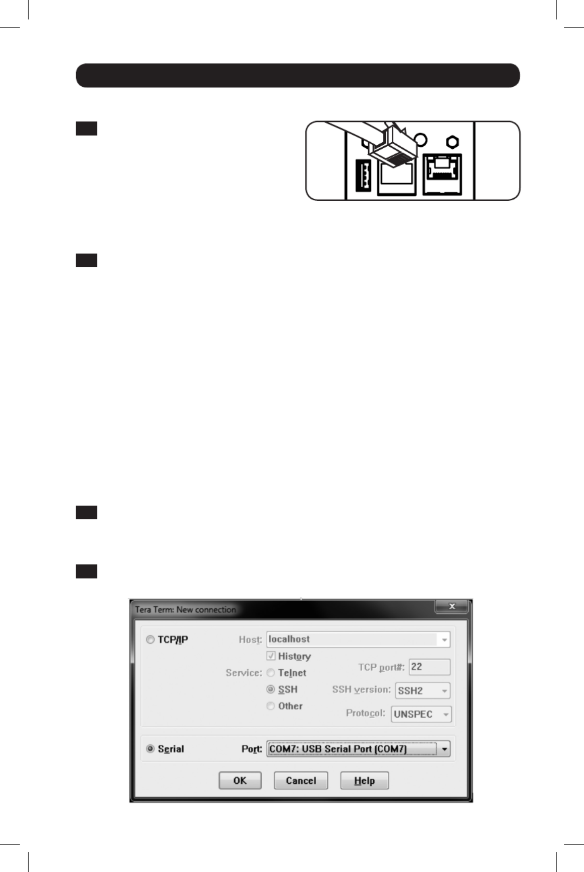
3-1 Connect Network Interface to
Network: Connect a standard Ethernet
patch cable to your network using the
RJ45 Ethernet port on the PDU’s Network
Interface.
This port does not support PoE (Power Note:
over Ethernet) applications.
Static IP Address Assignment /
Terminal Menu Configuration Settings
4-1 The Network Interface can support a single static IPv4 Determine IP Information:
address (requires setting the IP address, subnet mask and gateway) and/or a single static
IPv6 address. In addition, the Network Interface can support a single static IPv4 or an IPv6
DNS address that is required to be entered.
4-2 Configure Terminal Emulation Program: Set your terminal emulation program to use the
COM port with its corresponding USB port.
The interface will attempt to obtain an IP address via DHCP. This may take as long as
several minutes, depending on your network environment.
3-2 To identify the IP address assigned to the Network Interface, Determine IP Address:
contact your network administrator and provide the MAC address of the Network Interface.
You can also determine the IP address locally at the card.
Start a terminal emulation program, such as Tera Term Pro. Configure the COM port
intended for use by following these settings: 115.2 Kbps, 8, NONE, 1. Using the included
RJ45 to DB9 cable (part number 73-1243), connect your PC to the PDU’s CONFIG port.
When the login prompt appears, login as / . When the Menu localadmin localadmin
appears, navigate to “3- Network Configuration”, then to “1- IP Configuration”. The
assigned IP address will be displayed. After you have determined the IP address, proceed
to the Test Network Connection section.
You may wish to request a long-term lease period for the IP address, depending on your Note:
application.
PowerAlert Device Manager and the PDU’s Network Interface support both IPv4 and IPv6. The Note:
card is set up by default to receive a DHCP address for IPv4, IPv6 or both. Receiving both addresses
allows connection to the card via either the IPv4 or IPv6 address.
16-10-211-933668.indb 5 12/22/2016 11:36:15 AM
6
Installation
4-3 Select Option 3: IPv4 setting, or Option 4: IPv6 settings. Select Option 1: Method. Select
Option 2: Static.
Assign the address, subnet mask, gateway, etc. Save your settings by selecting “ ” (apply). A
Choose “ ” to restart PowerAlert now. Close your terminal session. y
4-4 Remove the cable and proceed to the Remove Cable: Test Network Connection section.
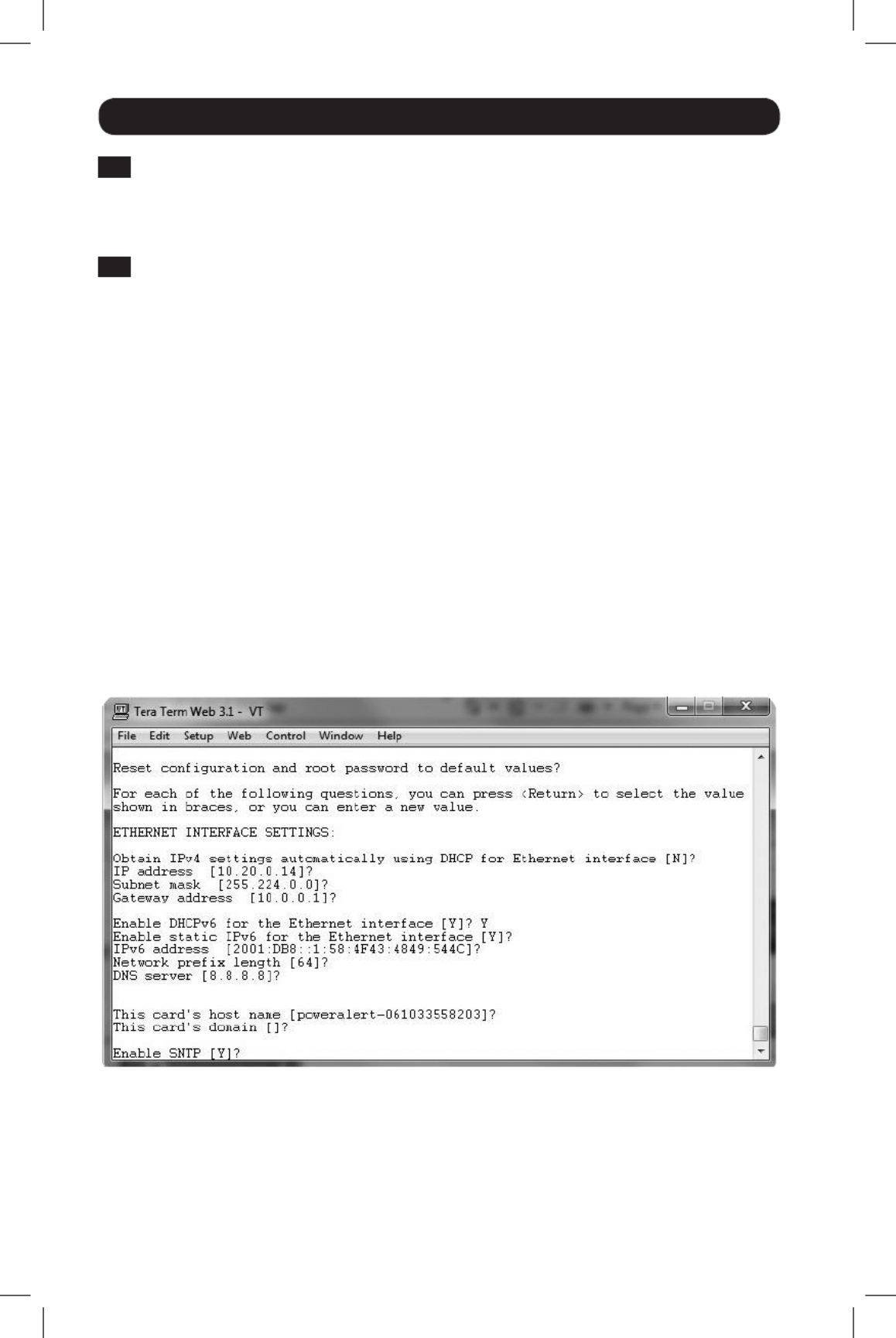
Network Settings
Follow the prompts to configure IPv4 and IPv6 address settings. The default terminal mode
password is TrippLite. Sample IP settings are shown—supply your own IP information when you
configure your card.
ETHERNET INTERFACE SETTINGS:
Obtain IPv4 settings automatically using DHCP for Ethernet interface? [Y]
IP address? [10.1.0.165]
Subnet mask? [255.0.0.0]
Gateway address? [10.0.0.1]
Enable DHCPv6 for the Ethernet interface? [Y]
Enable static IPv6 for the Ethernet interface? [N]
IPv6 address? [2001:DB8::1:58:4F43:4849:544C]
Network prefix length? [64]
DNS server? [10.0.0.8]
This card’s host name? [poweralert-061033462177]
This card’s domain? [tlsoftwaredev.local]
16-10-211-933668.indb 6 12/22/2016 11:36:15 AM
7
Installation
Enable SNTP? [Y]
Enable FTP? [Y]
Port number? [21]
Enable HTTP? [Y]
Port number? [ 80]
Enable HTTPS? [Y]
Port number? [443]
Enable Telnet Menu? [Y]
Port number? [23]
Enable Telnet Programs? [Y]
Port number? [5214]
Enable SSH Menu? [Y]
Port number? [22]
Enable SSH Programs? [Y]
Port number? [2112]
Enable SNMP? [Y]
Port number? [161]
Enable SNMPv1? [Y]
Enable SNMPv2c? [Y]
Enable SNMPv3? [Y]
You can also change the root password, real-time clock and other settings. (Tripp Lite
recommends against changing the default settings unless you are an advanced user with a
specific purpose.) After you have finished entering settings, the PDU will save changes to memory
and reboot (this may take several minutes). After the PDU reboots, the initialization page should
display the new static IP settings.
4-6 Remove the serial cable from the PDU and proceed to Step Remove Serial Cable: 5-1 .
Network Service Configuration
The following prompts configure the connection methods the Network Interface will accept.
Network Connection
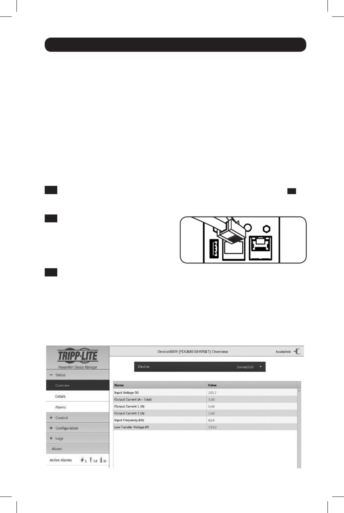
5-1 While the Connect PDU to Network:
PDU is powered, connect a standard
Ethernet patch cable to the RJ-45
Ethernet port on the PDU.
Note: This port is not compatible with PoE
(Power over Ethernet) applications.
5-2 Test Network Connection: After an IP address has been assigned to the card, try to
access it with a Web browser. Open a supported web browser on a computer connected
to the network and enter http:// or https:// followed by the IP address. The login screen
for PowerAlert Device Manager will display. The default user name is and the localadmin
password is . After you enter the user name and password, the PowerAlert localadmin
Device Manager Overview page will appear in the browser window. For more information
about configuration and operation of the managed device, refer to the LX Platform User’s
Guide located in the support section of the product web page.
Note: Supports Internet Explorer, Firefox and Chrome Web browsers.
16-10-211-933668.indb 7 12/22/2016 11:36:16 AM

UP
DOWN
A
E
B
C
D
8
Digital Load Meter
1 This button Select Bank Button: A
can be pressed to show total current for
each bank. Pressing this button once
will display the total current for all of
the Bank 1 outlets, located nearest to
the input cord. The LED for Bank 1 D
will illuminate and the total Amp current
for Bank 1 outlets will display on the
LED screen C. Pressing this button A
a second time will produce the same
results for Bank 2. Pressing the button a
third time will display total PDU current
and both Bank 1 and Bank 2 LEDs will
light. Pressing the button additional
times will repeat the cycle.
If you press and hold this button for
four seconds, the numbers in the LED
Amps display C will flip for mounting
versatility. The unit can be mounted with
the power cord facing the top or bottom
while still being able to read the display.
2 Select Outlet Button: This button B can be pressed to show the current for each
individual outlet. The LED located next to the selected outlet and the LED for the Bank
to which the outlet belongs (D or E) will flash when the total current for that outlet is
displayed (in amps) on the LED screen C. Pressing this button a second time will produce
the same results for outlet 2, pressing a third time for outlet 3 and so on through all the
outlets.
If you press and hold this button B for 4 seconds you can display the IP Address assigned
to the unit in the LED screen C. The default is no address assigned. If this is the case,
“ ” will display, one letter at a time. If there is an IP Address programmed, the no address
address will display 1 digit at a time with dashes (-) representing dots or periods (.).
Features
Outlets: During normal operation, the outlets distribute AC power to
connected equipment.
Outlet LED: Once the unit is powered-on, each outlet individually ramps
up and each outlet LED will illuminate when the associated outlet is ready
to distribute live AC power.
IEC-60320-C13
IEC-60320-C19 NEMA 5-15/20R
16-10-211-933668.indb 8 12/22/2016 11:36:18 AM
9
Features
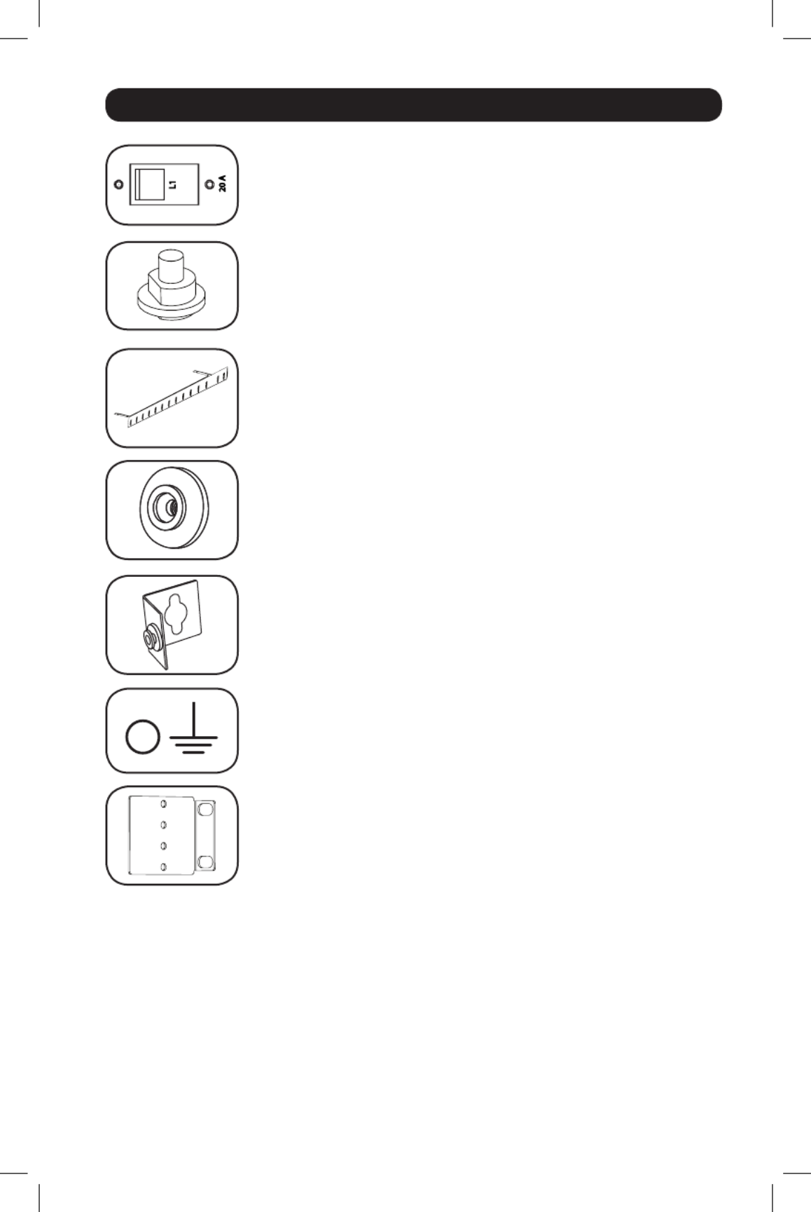
Circuit Breaker (Select Models): Each bank has its own breaker
labeled Bank 1 and Bank 2. If the connected equipment load exceeds
the Maximum Load Rating for that bank of the PDU, the circuit breaker
will trip.
Circuit Breaker (Select Models): If the connected equipment load
exceeds the Maximum Load Rating of the PDU, the circuit breaker will
trip. Disconnect excess equipment and allow the breaker to cool before
depressing the plunger to reset the breaker.
Cord Retention Bracket: Provides secure attachment points for
connected equipment cords.
Mounting Buttons: Come pre-installed on the back side of the PDU and
are used for toolless mounting.
Note: Four additional mounting buttons are included for alternate rack styles.
PDUMVROTATEBRKT Mounting Accessory: Use these V-shaped
brackets to mount the PDU with its outlets facing the rear of the rack.
Ground Screw: Use this to connect any equipment that requires a
chassis ground.
Mounting Brackets: Use these brackets to mount the PDU.
16-10-211-933668.indb 9 12/22/2016 11:36:20 AM

10
Features
Network Interface
A Ethernet Port: RJ45 jack connects the PDU’s Network Interface to the network using a
standard Ethernet patch cable. LEDs A1 and A2 indicate the operating conditions (shown in
the table below).
B RJ45 Configuration Port: Use this port to provide a direct terminal connection to a
computer with a terminal emulation program. An RJ45 to DB9 cable (part number 73-
1243) is included with the PDU. To request a replacement cable, visit www.tripplite.com for
ordering information.
C USB Type-A Port: Use this port to connect a Tripp Lite EnviroSense2 module (E2MT,
E2MTDO, E2MTDI, E2MTHDI) for a variety of environmental monitoring and control options.
See www.tripplite.com for more information about these modules.
Do not connect a keyboard or mouse to this port.Note:
D Reset Button: Accessible through a small hole on the faceplate above the RJ45
Configuration Port. Press once to reset the Network Interface. Press and hold for 15
seconds to reset the Network Interface to factory default settings.
PDU loads will not be affected.Note:
E Status LED: Shows the Network Interface status (shown in the table below).
Identifier LED Function LED Color Status Description
A1 Ethernet Link/
Activity Indicator
Green Flashing There is network activity on the port
Off
There is no network activity on the port
A2 Ethernet Network
Speed Indicator
Yellow On steady 100 Mbps network speed
Off 10 Mbps speed if A1 is flashing
Off No network activity if A1 is also off
E Network
Interface Status
Green On steady Normal operation
Green Single
flash
Power up indicator
Green/
Orange
Off No power or card is initializing
Green/
Orange
Alternating
(~1/sec.)
Software update in progress
Green/
Orange
Alternating
(~2/sec.)
Restoring factory default
configuration
ABC
D E A1 A2
16-10-211-933668.indb 10 12/22/2016 11:36:20 AM

12
Warranty and Product Registration
2- YEAR LIMITED WARRANTY
Seller warrants this product, if used in accordance with all applicable instructions, to be free from original defects
in material and workmanship for a period of 2 years from the date of initial purchase. If the product should
prove defective in material or workmanship within that period, Seller will repair or replace the product, in its sole
discretion. Service under this Warranty can only be obtained by your delivering or shipping the product (with all
shipping or delivery charges prepaid) to: Tripp Lite, 1111 W. 35th Street, Chicago, IL 60609 USA. Seller will pay
return shipping charges. Visit www.tripplite.com/support before sending any equipment back for repair.
THIS WARRANTY DOES NOT APPLY TO NORMAL WEAR OR TO DAMAGE RESULTING FROM ACCIDENT, MISUSE,
ABUSE OR NEGLECT. SELLER MAKES NO EXPRESS WARRANTIES OTHER THAN THE WARRANTY EXPRESSLY
SET FORTH HEREIN. EXCEPT TO THE EXTENT PROHIBITED BY APPLICABLE LAW, ALL IMPLIED WARRANTIES,
INCLUDING ALL WARRANTIES OF MERCHANTABILITY OR FITNESS, ARE LIMITED IN DURATION TO THE
WARRANTY PERIOD SET FORTH ABOVE; AND THIS WARRANTY EXPRESSLY EXCLUDES ALL INCIDENTAL AND
CONSEQUENTIAL DAMAGES. (Some states do not allow limitations on how long an implied warranty lasts,
and some states do not allow the exclusion or limitation of incidental or consequential damages, so the above
limitations or exclusions may not apply to you. This Warranty gives you specific legal rights, and you may have
other rights which vary from jurisdiction to jurisdiction).
WARNING: The individual user should take care to determine prior to use whether this device is suitable, adequate
or safe for the use intended. Since individual applications are subject to great variation, the manufacturer makes
no representation or warranty as to the suitability or fitness of these devices for any specific application.
PRODUCT REGISTRATION
Visit www.tripplite.com/warranty today to register your new Tripp Lite product.You’ll be automatically entered into
a drawing for a chance to win a FREE Tripp Lite product!*
* No purchase necessary. Void where prohibited. Some restrictions apply. See website for details.
FCC Notice, Class A
This device complies with part 15 of the FCC Rules. Operation is subject to the following two conditions: (1)
This device may not cause harmful interference, and (2) this device must accept any interference received,
including interference that may cause undesired operation.
Note: This equipment has been tested and found to comply with the limits for a Class A digital device, pursuant
to part 15 of the FCC Rules. These limits are designed to provide reasonable protection against harmful
interference when the equipment is operated in a commercial environment. This equipment generates, uses,
and can radiate radio frequency energy and, if not installed and used in accordance with the instruction
manual, may cause harmful interference to radio communications. Operation of this equipment in a residential
area is likely to cause harmful interference in which case the user will be required to correct the interference
at his own expense. The user must use shielded cables and connectors with this equipment. Any changes or
modifications to this equipment not expressly approved by
Tripp Lite could void the user’s authority to operate this equipment.
Regulatory Compliance Identification Numbers
For the purpose of regulatory compliance certifications and identification, your Tripp Lite product has been assigned
a unique series number. The series number can be found on the product nameplate label, along with all required
approval markings and information. When requesting compliance information for this product, always refer to the
series number. The series number should not be confused with the marketing name or model number of the product.
WEEE Compliance Information for Tripp Lite Customers and Recyclers (European Union)
Under the Waste Electrical and Electronic Equipment (WEEE) Directive and implementing regulations, when
customers buy new electrical and electronic equipment from Tripp Lite they are entitled to:
• Send old equipment for recycling on a one-for-one, like-for-like basis (this varies depending on the country)
• Send the new equipment back for recycling when this ultimately becomes waste
Tripp Lite has a policy of continuous improvement. Specifications are subject to change without notice.
1111 W. 35th Street, Chicago, IL 60609 USA • www.tripplite.com/support
16-10-211-933668.indb 12 12/22/2016 11:36:21 AM

14
Instrucciones de seguridad importantes
GUARDE ESTAS INSTRUCCIONES
Este manual contiene instrucciones y advertencias que deben seguirse durante la
instalación, el funcionamiento y el almacenamiento de este producto. Si no sigue
estas instrucciones y advertencias puede afectar la garantía del producto.
• El PDU proporciona la conveniencia de múltiples tomacorrientes, pero NO proporciona
protección contra sobretensión o ruido en la línea para los equipos conectados.
• El PDU está diseñada solo para uso en interiores en un entorno controlado lejos de humedad
excesiva, temperaturas extremas, contaminantes conductivos, polvo o luz del sol directa.
• Mantiene la temperatura ambiente interior entre 0°C y 50°C.
• El PDU debe ser instalado solamente por un técnico calificado.
• No intente instalar el PDU en una superficie inestable o no segura.
• Instale de acuerdo con los reglamentos eléctricos locales. Asegúrese de usar para la
instalación la protección adecuada contra sobrecorriente, de acuerdo con la especificación de
la clavija o del equipo.
• Conecte el PDU a un tomacorriente que esté de acuerdo a los códigos locales de construcción
y que esté correctamente protegido contra corrientes excesivas, cortocircuitos y fallas de
conexión a tierra.
• Los tomacorrientes eléctricos que suministran energía al equipo deben instalarse próximos al
equipo y ser fácilmente accesibles.
• No conecte El PDU a un toma corriente que no esté a tierra o cables de extensión o
adaptadores que eliminen la conexión a tierra.
• Asegúrese de proporcionar un dispositivo local de desconexión, que sea fácilmente accesible,
en cualquier modelo que esté instalado permanentemente sin una clavija.
• Nunca intente instalar equipos eléctricos durante una tormenta eléctrica.
• El equipo individual conectado al PDU no debe consumir más corriente que la de la
especificación de cada tomacorriente individual del PDU.
• La carga total conectada al PDU no debe exceder la capacidad de carga máxima del PDU.
• No intente modificar el PDU, las clavijas de entrada o los cables de alimentación.
• No perfore ni intente abrir ninguna parte del gabinete del PDU. No tiene partes a las que el
usuario pueda dar servicio.
• No intente usar el PDU si se daña cualquier parte.
• No se recomienda el uso de este equipo en aplicaciones de soporte de vida en donde la falla
de este equipo pueda consecuentemente causar la falla del equipo de soporte de vida o
afectar significativamente su seguridad o efectividad.
16-10-211-933668.indb 14 12/22/2016 11:36:21 AM

1-2
1-1
1-3 1-4
PDUMVR30HVNET se muestra
15
Instalación
Montaje de la PDU
Nota: Las ilustraciones pueden diferir del modelo de la PDU. Independientemente de la configuración,
el usuario debe determinar la aptitud de las herramientas y los pasos antes de montarlo. La PDU y las
herramientas incluidas están diseñadas para racks comunes y racks y pueden no ser adecuadas para todas
las aplicaciones. La configuración exacta puede variar. Se incluyen tornillos para unir los soportes de montaje
y el estante de retención del cable a la PDU. Utilice sólo los tornillos suministrados por el fabricante, o su
equivalente exacto (#6-32, ¼ pulg. cabeza plana).
Si instala un PDU en un rack que tenga ranuras de instalación de botón, sólo necesita realizar los
pasos para la instalación sin herramientas (paso 1-1 ) Si su rack no tiene ranuras de instalación
de botón, proceda a paso 1-2.
Instalación sin Herramienta
1-1 Fije los botones de instalación incluidos
al PDU. Posicione el PDU como desee
en el gabinete de rack, alinee los
botones con las ranuras de instalación
del rack y deslice el PDU a su posición.
Nota: Para instalar el PDU con sus
tomacorrientes orientado hacia la parte
posterior del rack, use el accesorio
PDUMVROTATEBRKT incluido. Está ménsula
en forma de V proporciona un botón de
instalación en una pata de la V y una
ranura de instalación de botón en la otra,
reposicionando efectivamente los botones de
instalación. Para ver una imagen, consulte la
sección de .Características
Instalación Normal
1-2 Fije las ménsulas de instalación al PDU.
1-3 Fije el(los) soporte(s) de (Opcional)
sujeción del cable al PDU.
1-4 Fije el PDU a un riel vertical en su
rack o gabinete. Use las partes para
instalación incluidas, para acoplar los
soportes de instalación al riel.
16-10-211-933668.indb 15 12/22/2016 11:36:23 AM

18
Instalación
Parámetros de Red
Siga las indicaciones para configurar los parámetros de dirección IPv4 e IPv6. La contraseña
predeterminada del modo de terminal es TrippLite. Se muestran parámetros de muestra de IP—
suministre su propia información de IP cuando configure su terjeta.
PARÁMETROS DE INTERFAZ DE ETHERNET:
Obtain IPv4 settings automatically using DHCP for Ethernet interface? [Y]
IP address? [10.1.0.165]
Subnet mask? [255.0.0.0]
Gateway address? [10.0.0.1]
Enable DHCPv6 for the Ethernet interface? [Y]
Enable static IPv6 for the Ethernet interface? [N]
IPv6 address? [2001:DB8::1:58:4F43:4849:544C]
Network prefix length? [64]
DNS server? [10.0.0.8]
This card’s host name? [poweralert-061033462177]
This card’s domain? [tlsoftwaredev.local]
4-3 Seleccione Opción 3: Parámetro IPv4, o Opción 4: Parámetros IPv6. Seleccione Opción 1:
Método. Seleccione Opción 2: Estática
Asigne la dirección, máscara de subred, portal, etc. Guarde sus parámetros seleccionando
“A” (aplicar). Elija “y” para reiniciar ahora PowerAlert. Elija su sesión de terminal.
4-4 Retire el Cable: Retire el cable y proceda a la sección de .Probar Conexión de Red
16-10-211-933668.indb 18 12/22/2016 11:36:24 AM
Specyfikacje produktu
| Marka: | Tripp Lite |
| Kategoria: | Listwa zasilająca |
| Model: | PDUMVR30HVNET |
Potrzebujesz pomocy?
Jeśli potrzebujesz pomocy z Tripp Lite PDUMVR30HVNET, zadaj pytanie poniżej, a inni użytkownicy Ci odpowiedzą
Instrukcje Listwa zasilająca Tripp Lite

21 Września 2024
14 Września 2024
13 Września 2024
11 Września 2024
10 Września 2024
9 Września 2024
9 Września 2024
9 Września 2024
8 Września 2024
7 Września 2024
Instrukcje Listwa zasilająca
- Listwa zasilająca Sven
- Listwa zasilająca Philips
- Listwa zasilająca Yato
- Listwa zasilająca StarTech.com
- Listwa zasilająca Nedis
- Listwa zasilająca ATen
- Listwa zasilająca APC
- Listwa zasilająca Icy Box
- Listwa zasilająca Gembird
- Listwa zasilająca V7
- Listwa zasilająca Digitus
- Listwa zasilająca EVOline
- Listwa zasilająca Oehlbach
- Listwa zasilająca DataVideo
- Listwa zasilająca Panduit
- Listwa zasilająca Intellinet
- Listwa zasilająca Kindermann
- Listwa zasilająca Ewent
- Listwa zasilająca GoGen
- Listwa zasilająca Oregon Scientific
- Listwa zasilająca Hama
- Listwa zasilająca Ubiquiti Networks
- Listwa zasilająca CyberPower
- Listwa zasilająca Vivanco
- Listwa zasilająca Eaton
- Listwa zasilająca Geist
- Listwa zasilająca Qian
- Listwa zasilająca Anton/Bauer
- Listwa zasilająca Act
- Listwa zasilająca Brennenstuhl
- Listwa zasilająca Eglo
- Listwa zasilająca Caliber
- Listwa zasilająca Eminent
- Listwa zasilająca Energenie
- Listwa zasilająca Steren
- Listwa zasilająca Ufesa
- Listwa zasilająca Konig
- Listwa zasilająca HQ
- Listwa zasilająca REV
- Listwa zasilająca Panamax
- Listwa zasilająca Furman
- Listwa zasilająca Legrand
- Listwa zasilająca Bachmann
- Listwa zasilająca Kondator
- Listwa zasilająca Bauhn
- Listwa zasilająca Altronix
- Listwa zasilająca Middle Atlantic
- Listwa zasilająca Huslog
Najnowsze instrukcje dla Listwa zasilająca

10 Marca 2025
10 Marca 2025
9 Marca 2025
27 Lutego 2025
21 Lutego 2025
20 Lutego 2025
20 Lutego 2025
14 Stycznia 2025
12 Stycznia 2025

31 Grudnia 2025