Instrukcja obsługi Supermicro SuperServer E100-9AP-IA
Supermicro
serwer
SuperServer E100-9AP-IA
Przeczytaj poniżej 📖 instrukcję obsługi w języku polskim dla Supermicro SuperServer E100-9AP-IA (89 stron) w kategorii serwer. Ta instrukcja była pomocna dla 2 osób i została oceniona przez 2 użytkowników na średnio 4.5 gwiazdek
Strona 1/89

USER’S MANUAL
Revision 1.0
SuperServer®
E100-9AP-IA

The information in this User’s Manual has been carefully reviewed and is believed to be accurate. The vendor assumes
no responsibility for any inaccuracies that may be contained in this document, and makes no commitment to update
or to keep current the information in this manual, or to notify any person or organization of the updates. Please Note:
For the most up-to-date version of this manual, please see our website at www.supermicro.com.
Super Micro Computer, Inc. ("Supermicro") reserves the right to make changes to the product described in this manual
at any time and without notice. This product, including software and documentation, is the property of Supermicro and/
or its licensors, and is supplied only under a license. Any use or reproduction of this product is not allowed, except
as expressly permitted by the terms of said license.
IN NO EVENT WILL Super Micro Computer, Inc. BE LIABLE FOR DIRECT, INDIRECT, SPECIAL, INCIDENTAL,
SPECULATIVE OR CONSEQUENTIAL DAMAGES ARISING FROM THE USE OR INABILITY TO USE THIS PRODUCT
OR DOCUMENTATION, EVEN IF ADVISED OF THE POSSIBILITY OF SUCH DAMAGES. IN PARTICULAR, SUPER
MICRO COMPUTER, INC. SHALL NOT HAVE LIABILITY FOR ANY HARDWARE, SOFTWARE, OR DATA STORED
OR USED WITH THE PRODUCT, INCLUDING THE COSTS OF REPAIRING, REPLACING, INTEGRATING,
INSTALLING OR RECOVERING SUCH HARDWARE, SOFTWARE, OR DATA.
Any disputes arising between manufacturer and customer shall be governed by the laws of Santa Clara County in the
State of California, USA. The State of California, County of Santa Clara shall be the exclusive venue for the resolution
of any such disputes. Supermicro's total liability for all claims will not exceed the price paid for the hardware product.
FCC Statement: This equipment has been tested and found to comply with the limits for a Class B digital device
pursuant to Part 15 of the FCC Rules. These limits are designed to provide reasonable protection against harmful
interference when the equipment is operated in a commercial environment. This equipment generates, uses, and can
radiate radio frequency energy and, if not installed and used in accordance with the manufacturer’s instruction manual,
may cause harmful interference with radio communications. Operation of this equipment in a residential area is likely
to cause harmful interference, in which case you will be required to correct the interference at your own expense.
California Best Management Practices Regulations for Perchlorate Materials: This Perchlorate warning applies only
to products containing CR (Manganese Dioxide) Lithium coin cells. “Perchlorate Material-special handling may apply.
See ”.www.dtsc.ca.gov/hazardouswaste/perchlorate
WARNING: Handling of lead solder materials used in this product may expose you to lead, a
chemical known to the State of California to cause birth defects and other reproductive harm.
The products sold by Supermicro are not intended for and will not be used in life support systems, medical equipment,
nuclear facilities or systems, aircraft, aircraft devices, aircraft/emergency communication devices or other critical
systems whose failure to perform be reasonably expected to result in signicant injury or loss of life or catastrophic
property damage. Accordingly, Supermicro disclaims any and all liability, and should buyer use or sell such products
for use in such ultra-hazardous applications, it does so entirely at its own risk. Furthermore, buyer agrees to fully
indemnify, defend and hold Supermicro harmless for and against any and all claims, demands, actions, litigation, and
proceedings of any kind arising out of or related to such ultra-hazardous use or sale.
Manual Revision 1.0
Release Date: October 12, 2018
Unless you request and receive written permission from Super Micro Computer, Inc., you may not copy any part of this
document. Information in this document is subject to change without notice. Other products and companies referred
to herein are trademarks or registered trademarks of their respective companies or mark holders.
Copyright © 2018 by Super Micro Computer, Inc.
All rights reserved.
Printed in the United States of America

3
Preface
Preface
About this Manual
This manual is written for professional system integrators and PC technicians. It provides
information for the installation and use of the SuperServer E100-9AP-IA. Installation and
maintenance should be performed by experienced technicians only.
Please refer to the E100-9AP-IA server specications page on our website for updates on
supported memory, processors and operating systems (http://www.supermicro.com).
Notes
For your system to work properly, please follow the links below to download all necessary
drivers/utilities and the user’s manual for your server.
• Supermicro product manuals: http://www.supermicro.com/support/manuals/
• Product drivers and utilities: ftp://ftp.supermicro.com
• Product safety info: http://www.supermicro.com/about/policies/safety_information.cfm
If you have any questions, please contact our support team at:
support@supermicro.com
This manual may be periodically updated without notice. Please check the Supermicro website
for possible updates to the manual revision level.
Warnings
Special attention should be given to the following symbols used in this manual.
Warning! Indicates high voltage may be encountered when performing a procedure.
Warning! Indicates important information given to prevent equipment/property damage
or personal injury.

4
SuperServer E100-9AP-IA User's Manual
Contents
Chapter 1 Introduction
1.1 Overview ...............................................................................................................................7
1.2 System Features ..................................................................................................................8
1.3 Chassis Features .................................................................................................................9
Top Features .......................................................................................................................9
Side Chassis Features ......................................................................................................10
1.4 Motherboard Layout ...........................................................................................................11
Quick Reference Table ......................................................................................................12
System Block Diagram ......................................................................................................13
1.5 Server Installation and Setup .............................................................................................14
Unpacking the System ......................................................................................................14
Warnings and Precautions ................................................................................................14
Adding Components to your System ...............................................................................14
Installing Mounting Bracket ...............................................................................................15
Chapter 2 Maintenance and Component Installation
2.1 Removing Power ................................................................................................................16
2.2 Accessing the System ........................................................................................................16
2.3 Motherboard Components ..................................................................................................17
Processor ..........................................................................................................................17
Memory Support ................................................................................................................17
Installing Memory ..............................................................................................................18
Solid State Storage ..........................................................................................................19
Motherboard Battery .........................................................................................................19
Chapter 3 A2SAN-E I/O Introduction
3.1 Front I/O .............................................................................................................................20
3.2 I/O Ports and Connectors ..................................................................................................22
3.3 Internal Expansion Slots ....................................................................................................23
3.4 LED Indicators ....................................................................................................................25
Chapter 4 Software
4.1 Driver Installation ................................................................................................................26
4.2 SuperDoctor® 5 ...................................................................................................................27

5
Preface
Chapter 5 BIOS
5.1 Introduction .........................................................................................................................28
Starting the Setup Utility ...................................................................................................28
5.2 Main ....................................................................................................................................29
5.3 Advanced ............................................................................................................................31
5.4 Security ...............................................................................................................................55
5.5 Boot ....................................................................................................................................59
5.6 Save & Exit .........................................................................................................................61
Appendix A BIOS Error Codes
Appendix B Standardized Warning Statements for DC Systems
Appendix C System Specications
Appendix D Traditional Chinese Version Safety Warnings
Appendix E UEFI BIOS Recovery

6
Contacting Supermicro
Headquarters
Address: Super Micro Computer, Inc.
980 Rock Ave.
San Jose, CA 95131 U.S.A.
Tel: +1 (408) 503-8000
Fax: +1 (408) 503-8008
Email: marketing@supermicro.com (General Information)
support@supermicro.com (Technical Support)
Website: www.supermicro.com
Europe
Address: Super Micro Computer B.V.
Het Sterrenbeeld 28, 5215 ML
's-Hertogenbosch, The Netherlands
Tel: +31 (0) 73-6400390
Fax: +31 (0) 73-6416525
Email: sales@supermicro.nl (General Information)
support@supermicro.nl (Technical Support)
rma@supermicro.nl (Customer Support)
Website: www.supermicro.nl
Asia-Pacic
Address: Super Micro Computer, Inc.
3F, No. 150, Jian 1st Rd.
Zhonghe Dist., New Taipei City 235
Taiwan (R.O.C)
Tel: +886-(2) 8226-3990
Fax: +886-(2) 8226-3992
Email: support@supermicro.com.tw
Website: www.supermicro.com.tw
SuperServer E100-9AP-IA User's Manual

7
Chapter 1: Introduction
Chapter 1
Introduction
1.1 Overview
The SuperServer E100-9AP-IA is a compact, embedded system comprised of the CSE-E101-IA
chassis and the A2SAN-E single processor motherboard. Refer to our website for information
on operating systems that have been certied for use with the system (www.supermicro.com).
This chapter provides a brief outline of the functions and features. In addition to the motherboard
and chassis, several important parts that are included with the system are listed below.
Main Parts List
Description QuantityPart Number
60W 12V 3.33A, AC to DC power adapter w/ terminal block 2pin MCP-250-10125-0N 1
Audio Cable Phone Jack and Plug (3.5-mm) L:100-mm MCP-280-10001-0B 1

8
SuperServer E100-9AP-IA User's Manual
1.2 System Features
The following table provides an overview of the main features of the E100-9AP-IA. Please
refer to Appendix C for additional specications.
System Features
Motherboard
A2SAN-E
Chassis
Compact Embedded Box for 3.5" high SBC, CSE-E101-IA
CPU
Intel® Atom x5-E3940 (System on a Chip) Socket BGA; CPU TDP support 9.5W, 2M cache, 4 cores, up to
1.8GHz
Cooling
No Fans for this chassis model enclosure
Memory
One DDR3L SODIMM socket; supports up to 8GB DDR3L Non-ECC SODIMM; Memory Type 1866 MHz speed
Expansion Slots
One Mini-PCI-E
One PCI-E M.2--Interface: B-Key 2280, supporting SATA/PCI-E or WWAN/GNSS devices
Power
One 60W DC power adapter with 2-pin terminal block
Input/Output Ports
LAN: Two Gigabit ports
USB: Four USB 2.0, two USB 3.0
Display: One HDMI, one VGA
DIO: One DB-9
COM: Four COM ports (2 x RS-232, 2 x RS-232/422/485)
Sound: One Line-out, One Mic-in
Front Panel
Power button; two LED status indicators
Dimensions
DxWxH: 4.96" x 7.64" x 3.15" (126 x 194 x 80mm)

9
Chapter 1: Introduction
1.3 Chassis Features
The CSE-E101-IA is a compact 3.5" height SBC chassis.
Top Features
The front of the chassis includes the control panel.
7
810
Figure 1-1. Chassis Top and Control Panel
Control Top I/O Panel Features
Item Features Description
1Grounding Screw Grounding screw for a grounding wire
2 LAN Ports Two Gigabit LAN ports
3 USB Ports Two front USB 3.0 ports
4 HDMI Port A front HDMI port
5 VGA Port A front VGA port
6 Power button
The main power switch applies or removes primary power from the power supply to the
server but maintains standby power. To perform most maintenance tasks, unplug the
system to remove all power.
7 COM Ports Four COM ports (COM1~4)
8 Expansion Port Port for expansion card
9 DIO Port DIO DB-9 connector port
10 HDD LED Indicates hard disk drive activity when ashing.
11 Power LED Indicates power is being supplied to the system power supply units. This LED is
illuminated when the system is operating normally.
1 2 3 5 64
11
9

10
SuperServer E100-9AP-IA User's Manual
Side Chassis Features
The chassis sides have additional input/output ports, as described in chapter 3.
Figure 1-2. Side Chassis Views
Side Chassis Features
Item Features Description
1Antenna Port Two antennae ports
2Power Input Port Use this port for the 60W DC power input.
3USB Ports Four rear USB
4MIC Port This is a port for a 2.5-mm microphone cable.
5Headphone Port This port is for a headphone 2.5-mm cable
5
4
2
1
3
1

11
Chapter 1: Introduction
1.4 Motherboard Layout
Below is a layout of the A2SAN-E with jumper, connector and LED locations shown. See the
table on the following page for descriptions. For detailed descriptions, pinout information and
jumper settings, refer to Chapter 3.
Figure 1-3. Motherboard Layout
Notes:
• Jumpers/LED indicators not indicated are used for testing only.
• Some connectors, jumpers and headers shown above may not be accessible or used by
the system and therefore should be considered unsupported/unused.
JMD1
JPW1
JMP1
JLPC80
JSMBUS1
J5
JPT1
DESIGNED IN USA
A2SAN-L
REV:1.02
BAR CODE
JGP1
BT1
JCOM1: COM1/COM2
JCOM2: COM3/COM4
CPU1
FAN1
JPME2
JPF1
LAN1LAN2
JD1
LVDS1
I-SATA1
JHDMI1
LED1
JLCDPWR1 JF1
JIP1
JPH1
AUDIO FP
USB6(3.1)
X
X
X
USB2/3
USB0/1
VGA
JF1 ONPWR
RST
X
HDD LED
PWR LED
SPEAKER
JD1:
USB4/5(3.0)
USB4/5 (3.0)
JHDMI
JIP1
JPME2
USB2/3
USB0/1
JGP1
LAN1
CPU1
FAN1
LVDS1
I-SATA1
JF1
JCOM2
JLCDPWR1
JCOM1 BT1 AUDIO FP
JPH1
JD1
LED1
LAN2USB6 (3.1)
VGA
JPF1
JSMBUS1
JLPC80
JMD1
JMP1
J5
JPW1
JPT1

12
SuperServer E100-9AP-IA User's Manual
Quick Reference Table
Jumper Description Default Setting
JLCDPWR1 LVDS Panel VCC Power 3.3V / 5V / 12V Pins 1-2 (3.3V), Pins 3-5 (5V), Pins 3-4 (12V)
JPF1 Power Force On Pins 1-2 (Power Force On)
JPME2 Manufacturing Mode Pins 1-2 (Normal)
LED Description Status
LED1 Power LED (for debugging only) Solid Green: S0 mode
Solid Red: S3/S4/S5 modes
Connector Description
BT1 Battery Connector
(To Clear CMOS, remove the battery, short the connectors and re-install the battery.)
FAN1*System Fan Header
I-SATA1*Intel® PCH SATA 3.0 Port
JCOM1: COM1/COM2
JCOM2: COM3/COM4
Serial COM Ports
(JCOM1 supports RS232/RS422/RS485, JCOM2 supports RS232)
JD1 Speaker Header
JF1 Control Panel Header
JGP1 DIO Connector
JHDMI HDMI Port
JIP1*Inverter Power Header
JMD1 M.2 Slot (B-KEY) (supports PCI-E Gen2 X1/SATA / USB 2.0)
JMP1 Mini PCI-E Slot (supports PCI-E Gen2 X1/USB 2.0)
JPH1* SATA Power Connector (for one HDD system)
JPW1 4-pin 12V-Standby R/A Type Power Connector
JSMBUS1 System Management Bus Header
JTPM1 Trusted Platform Module/Port 80 Connector (for debugging only)
LAN1 ~ LAN2 LAN (RJ45) Ports
LVDS1*Dual Channel 48-bit LVDS Connector*
USB4/5 Back Panel Universal Serial Bus (USB) 3.0 Ports
USB0/1, USB2/3 USB 2.0 Headers
VGA Back Panel VGA Port
Note: Connectors marked with an asterisk "*" are unused or unaccessible by the system and
cannot be used.

13
Chapter 1: Introduction
Figure 1-4. System Block Diagram
Note: This is a general block diagram and may not exactly represent the features on your
motherboard. See the System Specications appendix for the actual specications of your
motherboard.
System Block Diagram
USB 3.0
Intel
DDR3L non ECC SKU
DUAL CHANNEL
MAX. 8G SO-DIMM SUPPORTED
DDR3L 1866 MHz
Non-ECC-SODIMM0
DDI0
HDMI connector
SATA[1]
USB 3.0 [0]
SPI
FLASH
SPI 128Mb FST_SPI
USB 2.0 [0]
High Definition
REALTEK
ALC888S-VD2-GR FRONT AUDIO Header
I/O PANEL LAYOUT
USB 3.0
M.2 SLOT (B KEY)
USB 3.0 [1]
Rear USB3.0 connector (USB 0)
Rear USB3.0 connector (USB 1)
5.0Gb/s
5.0Gb/s USB 2.0 [1]
DDI1
SATA
6Gb/s
MUX
USB 2.0 [2]
USB 2.0 [7]
USB 2.0 [3]
USB 2.0 [4]
USB 2.0 [5]
480Mb/s
480Mb/s
LPC
SIO
Port 80 / Debug header
NCT6106D
Audio
SATA 6Gb/s
I-SATA0
SATA[0]
eDP
VGA
Rear USB2.0 Header (USB 3)
Rear USB2.0 Header (USB 2)
CH7517
DP to VGA Bridge
VGA Connector
PTN3460
DP to LVDSBridge
LVDS Connector
480Mb/s
480Mb/s
Front USB2.0 Header (USB 4)
Front USB2.0 Header (USB 5)
COM 3 / 4 (RS232)
PCIe Gen2 x 1
5.0GT/s
PCIE[0]
GLAN1
INTEL I210
PCIe Gen2 x 1
5.0GT/s
PCIE[2]
RJ45
GLAN2
INTEL I210
RJ45
PCIe Gen2 x 1
PCIE[1]
5.0GT/s
PCIe Gen2 x 1
5.0GT/s
PCIE[3]
Mini-PCIe Slot
PCIe Gen2 x 2
5.0GT/s x2
PCIE[4/5]
ASM1142
PCIe Gen2 X2 to USB3.1
TYPE C
480Mb/s
LAN 1
21
TYPE C
USB 3.1
HDMI
LAN 2
COM 1 /2 (RS232/RS422/RS485)

14
SuperServer E100-9AP-IA User's Manual
1.5 Server Installation and Setup
The server is shipped with the onboard processor and the motherboard installed in the
chassis. Several steps are necessary to begin using your server. You must add memory,
mount the hard disk drive, and mount the system in place.
Unpacking the System
Inspect the box in which the system was shipped and note if it was damaged. If the server
itself shows damage, le a damage claim with the carrier.
Warnings and Precautions
• Review the electrical and general safety precautions in Appendix B.
Adding Components to your System
• Memory: If your system is not already fully integrated with system memory, refer to Chapter
2 for details on compatible types of memory and the installation procedure.
• Drives and Storage: To add storage capabilities to your server, see Chapter 2.
• Input/Output: See Chapter 3 for I/O ports and connect them as needed.
• Software: See Chapter 4 for description and procedures for installing software, including
drivers and monitoring programs.

15
Chapter 1: Introduction
Installing Mounting Bracket
The chassis includes a mounting bracket that allows it to be mounted in any convenient space
in the work environment.
1. Install the bracket, using six screws through the holes in the bracket to secure the
bracket to the chassis.
2. Secure the bracket to the surface where you want the server to be mounted.
Figure 1-5. Installing Mounting Bracket

16
SuperServer E100-9AP-IA User's Manual
Chapter 2
Maintenance and Component Installation
This chapter provides instructions on installing and replacing main system components. To
prevent compatibility issues, only use components that match the specications and/or part
numbers given.
Installation or replacement of most components require that power rst be removed from the
system. Please follow the procedures given in each section.
2.1 Removing Power
Use the following procedure to ensure that power has been removed from the system. This
step is necessary when removing or installing non-hot-swap components or when replacing
a non-redundant power supply.
1. Use the operating system to power down the system.
2. After the system has completely shut down, disconnect the DC adapter power cord from
the power source.
3. Disconnect the power cord from the chassis.
2.2 Accessing the System
The E101 features a removable bottom cover to access to the inside of the chassis.
Removing the Bottom Cover
1. Power down the system as described in section 2.1.
2. Remove the eight screws that hold the cover in place.
3. Lift the cover up and o the chassis.
Caution: Except for short periods of time, do not operate the server without the cover in
place. The chassis cover must be in place to prevent misuse.

17
Chapter 2: Maintenance and Component Installation
2.3 Motherboard Components
Processor
The E100-9AP-IA features an embedded Intel® Atom x5-E3940 processor.
Memory Support
The A2SAN-E series motherboard supports up to 8 GB of DDR3L Non-ECC SODIMM memory
with speeds up to 1866 MHz in one memory slot.
Note: Check the Supermicro website for recommended memory modules.
Figure 2-2. Installing Memory SODIMM

18
SuperServer E100-9AP-IA User's Manual
2. Insert the SODIMM module vertically at about a 45 degree angle. Press down until the
module locks into place.
Align
Insert this
end rst Press down until the
module locks into place.
3. The side clips will automatically secure the SODIMM module, locking it into place.
Locking clip
SODIMM Removal
1. Push the side clips at the end of slot to release the SO-DIMM module.
2. Pull the SO-DIMM module up to remove it from the slot.
Installing Memory
Caution: Exercise extreme care when installing or removing DIMM modules to prevent
damage.
SO-DIMM Installation
1. Position the SODIMM module's bottom key so it aligns with the receptive point on the
slot.

19
Chapter 2: Maintenance and Component Installation
Solid State Storage
This motherboard supports an internally mounted solid state storage card by means of an
M.2 slot supporting SATA/PCI-E or WWAN/GNSS.
Installing the M.2 Card
1. Gently insert the M.2 card into the connector.
2. Use a screw to secure the M.2 card to the M2_SRW1 or M2_SRW2 stando.
Figure 2-3. Installing an M.2 Expansion Card
Motherboard Battery
The motherboard uses non-volatile memory to retain system information when system power
is removed. This memory is powered by a lithium battery residing on the motherboard.

20
SuperServer E100-9AP-IA User's Manual
Chapter 3
A2SAN-E I/O Introduction
This section describes the A2SAN-E I/O connectors and pin denition. Please review the
Safety Precautions in Appendix A before installing or removing components. Illustrations
showing front and rear I/O layouts and a motherboard layout indicating component locations
and I/O port locations may be found in Chapter 1.
Please review the Safety Precautions in Appendix B before installing or removing components.
3.1 Front I/O
LAN Ports
Two LAN ports (LAN1 ~ LAN2) are located on the I/O panel. These ports accept RJ45 type
cables. Please refer to the LED Indicator section for LAN LED information. See the table
below for pin dentions.
LAN Port0
Pin Denitions
Pin# Pin#Denition Denition
A1 TD1+ YEL-A11
A2 TD1- A12 YEL+
A3 TD2+ A13 GRN-/ORG+
A4 TD2- A14 GRN+/ORG-
A5 CT_VCC A15
A6 CT_VCC A16
A7 TD3+ A17
A8 TD3- A18
A9 TD4+ A19
A10 TD4- A20

21
Chapter 3 A2SAN-E I/O Introduction
Back Panel USB 3.0
Pin Denitions
Pin# Pin#Denition Denition
1 VBUS 10 VBUS
2 D1-N D2-N11
3 D1-P 12 D2-P
4 GND 13 GND
5 Stda_SSRX1-N 14 Stda_SSRX2-N
6 Stda_SSRX1-P 15 Stda_SSRX2-P
7 GND_DRAIN 16 GND_DRAIN
8 Stda_SSTX1-N 17 Stda_SSTX2-N
9 Stda_SSTX1-P 18 Stda_SSTX2-P
Universal Serial Bus (USB) Ports
There are two USB 3.0 ports (USB4/5) on the I/O panel. They give complete Plug & Play
and hot swapping capability. The USB interface is compliant with USB UHCI, Rev. 3.0. The
USB interface supports Plug and Play, which enables you to connect or disconnect a device
without turning o the system.
HDMI Port
The HDMI (High-Denition Multimedia Interface) port is used to display both high denition
video and digital sound through an HDMI-capable display, using the same (HDMI) cable.
VGA Port
The onboard VGA port is located next to HDMI port on the front I/O panel. Use this connection
for VGA display.
Power Button
Pin Denitions (JF1)
Pin# Denition
1 Signal
2 Ground
Power Button
The Power Button connection is located on pins 1 and 2 of JF1. Momentarily contacting both
pins will power on/o the system. This button can also be congured to function as a suspend
button (with a setting in the BIOS - see Chapter 5). To turn o the power in the suspend mode,
press the button for at least 4 seconds. See the table below for pin denitions.

22
SuperServer E100-9AP-IA User's Manual
DC Input Power Connector
The system supports a 12VDC DC power in through a connector on the rear I/O panel.
3.2 I/O Ports and Connectors
COM Ports
Four Serial COM ports are located on the rear I/O plate. COM1/COM2 supports RS-232/RS-
422/RS-485 ports, and COM3/COM4 supports only a RS-232 port. See the gure below for
pin denitions and tables below.
DIO D-SUB Connector
The DIO D-SUB connector is an 8-bit general purpose I/O expander via the SMBus. See the
table below for pin denitions.
DIO D-SUB Connector
Pin Denitions
Pin# Pin#Denition Denition
1 2GP_P3V3_GP7 GP_P3V3_GP6
3 4GP_P3V3_GP5 GP_P3V3_GP4
5 6GND GP_P3V3_GP3
7 8GP_P3V3_GP2 GP_P3V3_GP1
9 GP_P3V3_GP0
RS-232 D-SUB Connector
Pin Denitions
Pin# Pin#Denition Denition
1 2DCD RXD
3 4TXD DTR
5 6GND DSR
7 8RTS CTS
9 RI
RS-422 D-SUB Connector
Pin Denitions
Pin# Pin#Denition Denition
1 2TX- TX+
3 4RX+ RX-
5 6GND N/A
7 8N/A N/A
9 N/A

23
Chapter 3 A2SAN-E I/O Introduction
USB 2.0 Ports
Four rear panel I/O USB ports are located above the COM ports. See the table below for
pin denitions.
Rear Panel USB 2.0
Ports
Pin Denitions
Pin# Denition
1 VCC
3 USB Data-
3 USB Data+
4 Ground
M.2 Slot
M.2 is formerly known as Next Generation Form Factor (NGFF) and is located at JMD1 on
the bottom side of the motherboard. The M.2 slot is designed for internal mounting devices.
The A2SAN-E motherboard deploys a B-KEY for SATA/PCI-E SSD devices or USB/PCI-E
WWAN or GNSS card. The A2SAN-E deploys a 2280 screw hole location for a 2280 M.2
module. 2242 and 3042 M.2 modules are supported by an extender bracket to t on the 2280
screw hole location.
3.3 Internal Expansion Slots
RS-485 D-SUB Connector
Pin Denitions
Pin# Pin#Denition Denition
1 2DATA- DATA+
3 4N/A N/A
5 6GND N/A
7 8N/A N/A
9 N/A

24
SuperServer E100-9AP-IA User's Manual
Mini PCI-E Slot
The Mini PCI-E slot, located at JMP1 on the bottom side of the motherboard, is used to install
a compatible Mini PCI-E device. The Mini PCI-E slot supports modules which are USB or
PCI-E p24-x1 devices, such as wireless, GNSS, and bluetooth modules. See the table below for
pin denitions.
Mini PCI-E
Pin Denitions
Pin# Pin#Denition Denition
52 +3.3Vaux 51 NC
50 GND 49 NC
48 +1.5V 47 NC
46 NC 45 NC
44 NC 43 NC
42 NC 41 +3.3Vaux
40 GND 39 NC
38 USB_D+ 37 GND
36 USB_D- 35 GND
34 GND 33 PETp0
32 SMB_DATA 31 PETn0
30 SMB_CLK 29 GND
28 +1.5V 27 GND
26 GND 25 PERp0
24 +3.3Vaux 23 PERn0
22 PERST# 21 DET_CARD_PLUG
20 NC 19 NC
18 GND 17 NC
16 NC 15 GND
14 NC 13 REFCLK+
12 NC REFCLK-11
10 NC 9 GND
8 NC 7 CLKREQ#
6 1.5V 5 NC
4 GND 3 NC
2 3.3Vaux 1 WAKE#
25
Chapter 3 A2SAN-E I/O Introduction
3.4 LED Indicators
LAN Port LEDs
Two LAN ports (LAN 1 and LAN 2) are located on the I/O back panel of the motherboard.
Each Ethernet LAN port has two LEDs. The green LED indicates activity, while the other Link
LED may be green, amber, or o to indicate the speed of the connection.
LAN1/2 LED
(Connection Speed
Indicator)
LED Color Denition
O 10 Mb/s
Green 100 Mb/s
Amber 1 Gb/s
Power LED
LED1 is the Power LED. In S0 mode, this LED will be solid green. In S3/S4/S5 modes, this
LED will be solid red.
Onboard Power LED Indicator
LED Color Denition
O System O (power
cable not connected)
Solid Green S0 mode
Solid Red S3/S4/S5 modes

26
SuperServer E100-9AP User's Manual
Chapter 4
Software
This section describes the installation of drivers and management programs for the system.
4.1 Driver Installation
The Supermicro FTP site contains drivers and utilities for your system at ftp://ftp.supermicro.
com. Some of these must be installed, such as the chipset driver.
After accessing the FTP site, go into the CDR_Images directory and locate the ISO le for
your motherboard. Download this le to create a DVD of the drivers and utilities it contains.
(You may also use a utility to extract the ISO le if preferred.)
After creating a DVD with the ISO les, insert the disk into the DVD drive on your system
and the display shown in Figure 4-1 should appear.
Another option is to go to the Supermicro website at http://www.supermicro.com/products/.
Find the product page for your motherboard here, where you may download individual drivers
and utilities to your hard drive or a USB ash drive and install from there.
Note: To install the Windows OS, please refer to the instructions posted on our website at
http://www.supermicro.com/support/manuals/.
Figure 4-1. Driver & Tool Installation Screen

27
Chapter 4: Software
Note: Click the icons showing a hand writing on paper to view the readme les for each item.
Click the computer icons to the right of these items to install each item (from top to the bottom)
one at a time. After installing each item, you must re-boot the system before moving on to the
next item on the list. The bottom icon with a CD on it allows you to view the entire contents.
4.2 SuperDoctor® 5
The Supermicro SuperDoctor 5 is a program that functions in a command-line or web-based
interface for Windows and Linux operating systems. The program monitors such system health
information as CPU temperature, system voltages, system power consumption, fan speed,
and provides alerts via email or Simple Network Management Protocol (SNMP).
SuperDoctor 5 comes in local and remote management versions and can be used with Nagios
to maximize your system monitoring needs. With SuperDoctor 5 Management Server (SSM
Server), you can remotely control power on/o and reset chassis intrusion for multiple systems
with SuperDoctor 5 or IPMI. SuperDoctor 5 Management Server monitors HTTP, FTP, and
SMTP services to optimize the eciency of your operation.
Note: The default User Name and Password for SuperDoctor 5 is ADMIN / ADMIN.
Figure 4-2. SuperDoctor 5 Interface Display Screen (Health Information)

SuperServer E100-9AP-IA User's Manual
28
Chapter 5
BIOS
5.1 Introduction
This chapter describes the AMIBIOS™ Setup utility for the A2SAN-E motherboard. The BIOS
is stored on a chip and can be easily upgraded using a ash program.
Note: Due to periodic changes to the BIOS, some settings may have been added
or deleted and might not yet be recorded in this manual. Please refer to the Manual
Download area of our website for any changes to BIOS that may not be reected in
this manual.
Starting the Setup Utility
To enter the BIOS Setup Utility, hit the <Delete> key while the system is booting-up. (In
most cases, the <Delete> key is used to invoke the BIOS setup screen. There are a few
cases when other keys are used, such as <F1>, <F2>, etc.) Each main BIOS menu option
is described in this manual.
The Main BIOS screen has two main frames. The left frame displays all the options that can
be congured. “Grayed-out” options cannot be congured. The right frame displays the key
legend. Above the key legend is an area reserved for a text message. When an option is
selected in the left frame, it is highlighted in white. Often a text message will accompany it.
(Note that BIOS has default text messages built in. We retain the option to include, omit, or
change any of these text messages.) Settings printed in are the default values.Bold
A " "indicates a submenu. Highlighting such an item and pressing the <Enter> key will
open the list of settings within that submenu.
The BIOS setup utility uses a key-based navigation system called hot keys. Most of these
hot keys (<F1>, <F10>, <Enter>, <ESC>, <Arrow> keys, etc.) can be used at any time during
the setup navigation process.

Chapter 5: BIOS
29
5.2 Main
When you rst enter the AMI BIOS setup utility, you will enter the Main setup screen. You can
always return to the Main setup screen by selecting the Main tab on the top of the screen.
The Main BIOS setup screen is shown below.
System Date/System Time
Use this option to change the system date and time. Highlight System Date or System Time
using the arrow keys. Enter new values using the keyboard. Press the <Tab> key or the arrow
keys to move between elds. The date must be entered in MM/DD/YYYY format. The time
is entered in HH:MM:SS format.
Note: The time is in the 24-hour format. For example, 5:30 P.M. appears as 17:30:00.
Supermicro A2SAN-H
BIOS Version
Build Date
Memory Information
Total Memory: This displays the total size of memory available in the system.

SuperServer E100-9AP-IA User's Manual
30
Memory Speed: This displays the memory speed.
MRC Version
TXE FW
GOP
Chapter 5: BIOS
31
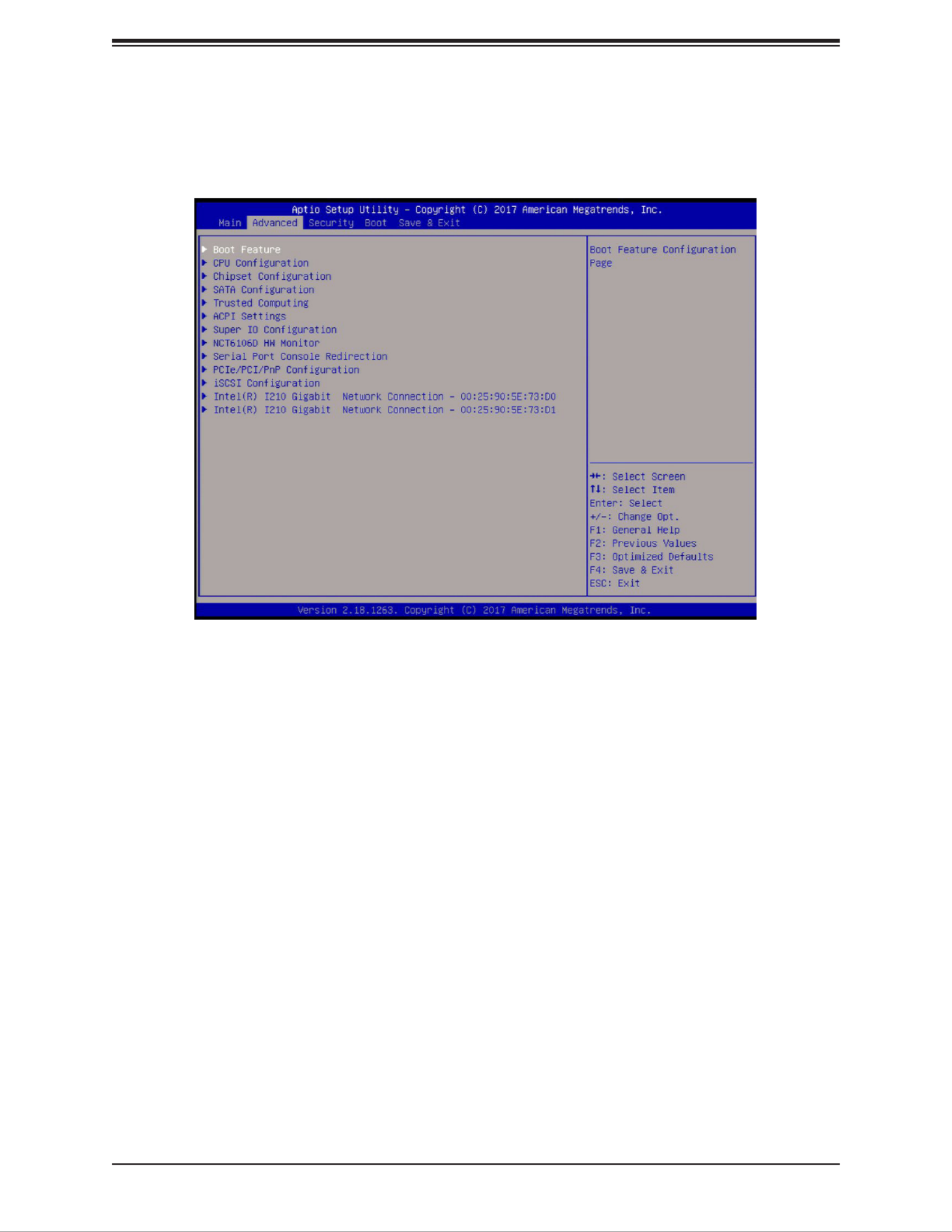
5.3 Advanced
Use this menu to congure Advanced settings:
Warning: Take caution when changing the Advanced settings. An incorrect value, a very high
DRAM frequency, or an incorrect BIOS timing setting may cause the system to malfunction.
When this occurs, restore the setting to the manufacture default setting.
Boot Feature
Quiet Boot
Use this feature to select the screen to display between POST messages or the OEM logo
at bootup. Select Disabled to display the POST messages. Select Enabled to display the
OEM logo instead of the normal POST messages. The options are Disabled and Enabled.
AddOn ROM Display Mode
This feature sets the display mode for the Option ROM. Select Keep Current to use the current
AddOn ROM display setting. Select Force BIOS to use the Option ROM display mode set by
the system BIOS. The options are Force BIOS and Keep Current.
Bootup NumLock State
This feature selects the Power-on state for the Numlock key. The options are O and On.

SuperServer E100-9AP-IA User's Manual
32
Wait For "F1" If Error
This feature forces the system to wait until the F1 key is pressed if an error occurs. The
options are Disabled and Enabled.
INT19 Capture Trap Response
Interrupt 19 is the software interrupt that handles the boot disk function. When this item is
set to Immediate, the ROM BIOS of the host adaptors will "capture" Interrupt 19 at bootup
immediately and allow the drives that are attached to these host adaptors to function as
bootable disks. If this item is set to Postponed, the ROM BIOS of the host adaptors will not
capture Interrupt 19 immediately and allow the drives attached to these adaptors to function
as bootable devices at bootup. The options are Immediate and Postponed.
Re-try Boot
If this feature is enabled, the BIOS will automatically reboot the system from a specied boot
device after its initial boot failure. The options are and EFI Boot.Disabled
Power Conguration
DeepSx Power Policies
Use this feature to congure the Advanced Conguration and Power Interface (ACPI) settings
for the system. Enable S5 to power o the whole system except the power supply unit (PSU)
and keep the power button alive so that the user can wake up the system by using a USB
keyboard or mouse. The options are Disabled and Enabled.
Watch Dog Function
If this feature is enabled, the Watch Dog timer will allow the system to reboot when it is inactive
for more than ve minutes. The options are Disabled and Enabled.
Power Button Function
This feature controls how the system shuts down when the power button is pressed. Select 4
Seconds Override for the user to power o the system after pressing and holding the power
button for 4 seconds or longer. Select Instant O to instantly power o the system as soon
as the user presses the power button. The options are 4 Seconds Override.Instant O and
Restore on AC Power Loss
Use this feature to set the power state after a power outage. Select Power O for the system
power to remain o after a power loss. Select Power On for the system power to be turned
on after a power loss. Select Last State to allow the system to resume its last power state
before a power loss. The options are Stay O, Power on, and Last State.
*This feature is not available when DeepSX Power Policies is Enabled.

Chapter 5: BIOS
33
CPU Conguration
The following CPU information will display:
• CPU model
• CPU Signature
• Microcode Patch
• Max CPU Speed
• Min CPU Speed
• Processor Cores
• Intel HT Technology
• Intel VT-x Technology
• L1 Data Cache
• L1 Code Cache
• L2 Cache
• L3 Cache
• Speed
• 64-bit
CPU Power Management
EIST
EIST (Enhanced Intel SpeedStep Technology) allows the system to automatically adjust
processor voltage and core frequency to reduce power consumption and heat dissipation.
The options are Disabled and Enabled.
Turbo Mode
Select Enabled for processor cores to run faster than the frequency specied by the
manufacturer. The options are Disabled and Enabled.
*This feature is available when EIST is Enabled.
Boot performance mode
This feature allows the user to select the performance state that the BIOS will set before
the operating system hando. The options are Max Performance and Max Power Saving.

SuperServer E100-9AP-IA User's Manual
34
Power Limit 1 Enable
Use this feature to set the power limit for the CPU. The options are Disabled and Enabled.
*This feature is available when EIST is set to Enabled.
Power Limit 1
Power Limit 1 Clamp Mode
Use this feature to set the PL1 clamp bit. The options are Disabled and Enabled.
Power Limit 1 Power
Use this item to congure the value for Power Limit 1. The value is in milli watts and the
step size is 125mW. Use the number keys on your keyboard to enter the value. The options
are Auto, 6, 7, 8, 9, 10, 11, 12, 13, 14, 15, 16, 17, 18, 19, 20, 21, 22, 23, 24, and 25.
Power Limit 1 Time Window
Use this feature to indicate the time window over which the TDP value should be maintained.
The default value is Auto. The options are Auto, 1, 2, 3, 4, 5, 6, 7, 8, 10, 12, 14, 16, 20,
24, 28, 32, 40, 48, 56, 64, 80, 96, 112, and 128.
Active Processor Cores
This feature determines how many CPU cores will be activated for each CPU. When Enabled
is selected, all cores in the CPU will be activated. Please refer to Intel's website for more
information. The options are Disabled and Enabled.
*If Active Processor Cores is set to Enabled, Core 0 - Core 3 will be available for
conguration:
Core 0
This feature is set to Enabled.
Core 1 - Core 3
Use this feature to enable or disable the CPU core. The options are Disabled and Enabled.
Intel® Virtualization Technology
Select Enable to use Intel Virtualization Technology to allow one platform to run multiple
operating systems and applications in independent partitions, creating multiple "virtual"
systems in one physical computer. The options are Disabled and Enabled.
VT-d
Select Enabled to enable Intel Virtualization Technology support for Direct I/O (VT-d) by
reporting the I/O device assignments to VMM through the DMAR ACPI Tables. This feature
oers fully-protected I/O resource-sharing across the Intel platforms, providing the user with
greater reliability, security, and availability in networking and data-sharing. The options are
Disabled and Enabled.

Chapter 5: BIOS
35
Monitor Mwait
Select Enabled to enable the Monitor/Mwait instructions. The Monitor instructions monitors
a region of memory for writes, and MWait instructions instruct the CPU to stop until the
monitored region begins to write. The options are Disabled and Enabled.
P-STATE Coordination
This feature allows the user to change the P-State (Power-Performance State) coordination
type. P-State is also known as "SpeedStep" for Intel processors. Select HW_ALL to change
the P-State coordination type for hardware components only. Select SW_ALL to change the
P-State coordination type for all software installed in the system. Select SW_ANY to change
the P-State coordination type for a software program in the system. The options are HW_All,
SW_ALL, and SW_ANY.
Chipset
Warning: Setting the wrong values in the following sections may cause the system to malfunc-
tion.
North Bridge
The following memory information will be displayed:
• Memory Slot 0
Graphics Conguration
GOP Conguration
GOP Driver
The Graphics Output Protocol (GOP) driver is a replacement for legacy video BIOS that
accesses UEFI protocols. The options are Enable and Disable.
LVDS Panel Support
Use this feature to select the supported IGFX graphics device ouput to the LVDS panel.
The options are Disabled and Enable.
*If LVDS Panel Support is set to Enable, Panel Select will be available for conguration:
Panel select
Use this feature to select the panel resolution. The options are , 800x600, 1024x768, Disable
1280x1024, 1366x768, 1680x1050, and 1920x1200.

SuperServer E100-9AP-IA User's Manual
36
IGD Conguration
Integrated Graphics Device
When enabled, the onboard graphics device will be used as the primary video display. The
options are Disable and Enable.
Primary Display
Use this feature to select the primary video display. The options are and PCIe.IGD
RC6 (Render Standby)
Select Enabled to enable render standby support. This is a power saving feature for the
onboard display that reduces power consumption. The options are Disable and Enable.
GTT Size
Use this feature to set the memory size to be used by the graphics translation table (GTT).
The options are 2MB, 4MB, and 8MB.
Aperture Size
Use this feature to set the Aperture size, which is the size of system memory reserved by
the BIOS for graphics device use. The options are 128MB, 256MB, and 512 MB.
DVMT Pre-Allocated
Dynamic Video Memory Technology (DVMT) allows dynamic allocation of system memory
to be used for video devices to ensure best use of available system memory based on the
DVMT 5.0 platform. The options are , 96M, 128M, 160M, 192M, 224M, 256M, 288M, 64M
320M, 352M, 384M, 416M, 448M, 480M, and 512M.
DVMT Total Gfx Mem
Use this feature to set the total memory size to be used by internal graphics devices based
on the DVMT 5.0 platform. The options are 128MB, and MAX.256MB,
GT PM Support
Use this feature to enable the IGFX Power Management function. The options are Enable
and Disable.
PAVP Enable
Protected Audio Video Path (PAVP) decodes Intel integrated graphics encrypted video. The
options are and Disable. Enable
Max TOLUD
This feature sets the maximum TOLUD value, which species the "Top of Low Usable DRAM"
memory space to be used by internal graphics devices, GTT Stolen Memory, and TSEG,
respectively, if these devices are enabled. The options are , 2.25 GB, 2.5 GB, 2.75 GB, 2 GB
and 3 GB.

Chapter 5: BIOS
37
South Bridge
HD Audio Conguration
HD-Audio Conguration
HD-Audio Support
Use this feature to enable high-denition audio support. The options are Disable and
Enable.
PCI Express Conguration
ASMedia USB Controller
ASPM
Use this feature to set the Active State Power Management (ASPM) level for a PCI-E
device. Select Auto for the system BIOS to automatically set the ASPM level based on
the system conguration. Select Disabled to disable ASPM support. The options are
Disable and L1.
PCIe Speed
Uses this feature to select the PCI speed for the device installed in the slot. The options
are Auto, Gen1, and Gen2.
M.2 SLOT
ASPM
Use this feature to set the Active State Power Management (ASPM) level for a PCI-E
device. Select Auto for the system BIOS to automatically set the ASPM level based on
the system conguration. Select Disabled to disable ASPM support. The options are
Disable, L0s, L1, L0sL1, and Auto.
PCIe Speed
Use this feature to select the PCI speed for the device installed in the M.2 slot. The op-
tions are , Gen1, and Gen2. Auto

SuperServer E100-9AP-IA User's Manual
38
Intel I210 Gigabit LAN
ASPM
Use this feature to set the Active State Power Management (ASPM) level for a PCI-E
device. Select Auto for the system BIOS to automatically set the ASPM level based on
the system conguration. Select Disabled to disable ASPM support. The options are
Disable, L0s, L1, L0sL1, and Auto.
PCIe Speed
Use this feature to select the PCI speed for the device installed in the slot. The options
are Auto, Gen1, and Gen2.
Mini PCIe
ASPM
Use this feature to set the Active State Power Management (ASPM) level for a PCI-E
device. Select Auto for the system BIOS to automatically set the ASPM level based on
the system conguration. Select Disabled to disable ASPM support. The options are
Disable, L0s, L1, L0sL1, and Auto.
PCIe Speed
Use this feature to select the PCI speed for the device installed in the slot. The options
are Auto, Gen1, and Gen2.

Chapter 5: BIOS
39
USB Conguration
USB3.0 Support
Select Enable for USB 3.0 support. The options are Enable and Disable.
XHCI Pre-Boot Driver
Select Enabled to enable XHCI (Extensible Host Controller Interface) support on a pre-boot
drive specied by the user. The options are Enable and Disable.
XHCI Hand-O
This is a work-around solution for operating systems that do not support XHCI (Extensible
Host Controller Interface) hand-o. The XHCI ownership change should be claimed by the
XHCI driver. The settings are and Disabled.Enabled
USB Rear I/O USB3.0
Select Enabled for rear I/O USB 3.0 support. The options are Enabled and Disabled.
USB Mass Storage Driver Support
Select Enabled for USB mass storage device support. The options are Disabled and
Enabled.
SATA Conguration
Chipset SATA
Use this feature to enable or disable the onboard SATA controller supported by the SoC. The
options are and Disable.Enable
SATA Mode Selection
Use this feature to select the mode for the installed SATA drives. The options are AHCI and
RAID.
Aggressive LPM (Link Power Management) Support
When this feature is set to Enabled, the SATA AHCI controller manages the power usage of
the SATA link. The controller will put the link in a low power mode during extended periods of
I/O inactivity, and will return the link to an active state when I/O activity resumes. The options
are Enabled and Disabled.
SATA Frozen
Use this feature to enable the HDD Security Frozen Mode. The options are Disabled and
Enabled.

SuperServer E100-9AP-IA User's Manual
40
SATA Port 0 - SATA Port 1
Port
Use this feature to enable of disable the specied SATA port. The options are Disabled and
Enabled.
SATA Port Hot Plug
This feature designates the SATA port specied for hot plugging. Set this item to Enabled for
hot-plugging support, which will allow the user to replace a SATA disk drive without shutting
down the system. The options are Enabled and Disabled.
Spin Up Device
When the value of an edge detect or the value of an image binary (pixel) of a device is from
0 to 1, select Enabled to allow the PCH to start a COMRESET initialization sequence on this
device. The options are Enabled and Disabled.
SATA Device Type
Use this feature to specify if the SATA port specied by the user should be connected to a
Solid State drive or a Hard Disk Drive. The options are Hard Disk Drive and Solid State Drive.
SATA Port DevSlp
DEVSLP is a signal that is sent to a SATA disk drive to tell it to enter a very low power state.
The options are and Enabled. Disabled
Trusted Computing
Security Device Support
If this feature and the TPM on the motherboard are both set to Enabled, onbaord security
devices will be enabled for TPM (Trusted Platform Module) support to enhance data integrity
and network security. Please reboot the system for a change on this setting to take eect.
The options are Disable and Enable.
*If Security Device Support is set to Enable, the following items will be available for
conguration:
The following Platform Conguration Register information will display:
Active PCR banks
Available PCR banks
SHA-1 PCR Bank
Use this feature to disable or enable the SHA-1 Platform Conguration Register (PCR) bank
for the installed TPM device. The options are Disabled and Enabled.

Chapter 5: BIOS
41
SHA256 PCR Bank
Use this feature to disable or enable the SHA256 Platform Conguration Register (PCR) bank
for the installed TPM device. The options are Disabled and Enabled.
Pending operation
Use this feature to schedule a TPM-related operation to be performed by a security device
for system data integrity. The options are None and TPM Clear.
Platform Hierarchy
Use this feature to disable or enable platform hierarchy for platform protection. The options
are Disabled and Enabled.
Storage Hierarchy
Use this feature to disable or enable storage hierarchy for cryptographic protection. The
options are Disabled and Enabled.
Endorsement Hierarchy
Use this feature to disable or enable endorsement hierarchy for privacy control. The options
are Disabled and Enabled.
TPM2.0 UEFI Spec Version
Use this feature to select the Trusted Computing Group (TCG) specication version. Version
TCG_1_2 is compatible with Windows 8 and 10. Version TCG_2 is compatible with Windows
10 or later. The options are TCG_1_2 and TCG_2.
Physical Presence Spec Version
Use this feature to select the Physical Presence Interface version. This interace uses the
ACPI and allows the operating system and BIOS to work together to provide a platform for
users to administer the TPM. The options are and 1.3.1.2
Device Select
Use this feature to select the TPM version. TPM 1.2 will restrict support to TPM 1.2 devices.
TPM 2.0 will restrict support for TPM 2.0 devices. Select Auto to enable support for both
versions. The default setting is Auto.

SuperServer E100-9AP-IA User's Manual
42
ACPI Settings
ACPI Sleep State
Use this feature to select which sleep state mode the system will enter when the Suspend
button is pressed. The options are Suspend Disabled and S3 (Suspend to RAM).
High Precision Timer
Select Enabled to activate the High Precision Event Timer (HPET) that produces periodic
interrupts at a much higher frequency than a Real-time Clock (RTC) does in synchronizing
multimedia streams, providing smooth playback, and reducing the dependency on other
timestamp calculation devices, such as an x86 RDTSC Instruction embedded in the CPU.
The High Precision Event Timer is used to replace the 8254 Programmable Interval Timer.
The options are Disable and Enable.
Super IO Conguration
Super IO Chip NCT6106D
Serial Port 1 Conguration
Serial Port
Select Enabled to enable the onboard serial port specied by the user. The options are
Disabled and Enabled.
Device Settings
This item displays the base I/O port address and the Interrupt Request address of a serial
port specied by the user.
Change Settings
This feature species the base I/O port address and the Interrupt Request address of Serial
Port 1. Select Auto to allow the BIOS to automatically assign the base I/O and IRQ address
to a serial port specied. The options are Auto, (IO=3F8h; IRQ=4), (IO=3F8h; IRQ=3, 4,
5, 6, 7, 9, 10, 11, 12), (IO=2F8h; IRQ=3, 4, 5, 6, 7, 9, 10, 11, 12), (IO=3E8h; IRQ=3, 4, 5,
6, 7, 9, 10, 11, 12), and (IO=2E8h; IRQ=3, 4, 5, 6, 7, 9, 10, 11, 12).
COM Port Mode
Use this item to select the COM port mode. The options are , RS422 Mode, RS232 Mode
and RS485 Mode.
Serial Port 2 Conguration
Serial Port
Select Enabled to enable the onboard serial port specied by the user. The options are
Disabled and Enabled.

Chapter 5: BIOS
43
Device Settings
This item displays the base I/O port address and the Interrupt Request address of a serial
port specied by the user.
Change Settings
This feature species the base I/O port address and the Interrupt Request address of Serial
Port 2. Select Auto to allow the BIOS to automatically assign the base I/O and IRQ address
to a serial port specied. The options are Auto, (IO=2F8h; IRQ=3), (IO=3F8h; IRQ=3, 4,
5, 6, 7, 9, 10, 11, 12), (IO=2F8h; IRQ=3, 4, 5, 6, 7, 9, 10, 11, 12), (IO=3E8h; IRQ=3, 4, 5,
6, 7, 9, 10, 11, 12), and (IO=2E8h; IRQ=3, 4, 5, 6, 7, 9, 10, 11, 12).
COM Port Mode
Use this item to select the COM port mode. The options are , RS422 Mode, RS232 Mode
and RS485 Mode.
Serial Port 3 Conguration
Serial Port
Select Enabled to enable the onboard serial port specied by the user. The options are
Disabled and Enabled.
Device Settings
This item displays the base I/O port address and the Interrupt Request address of a serial
port specied by the user.
Change Settings
This feature species the base I/O port address and the Interrupt Request address of Serial
Port 2. Select Auto to allow the BIOS to automatically assign the base I/O and IRQ address
to a serial port specied. The options are Auto, (IO=3E8h; IRQ=7), (IO=3E8h; IRQ=3, 4,
5, 6, 7, 9, 10, 11, 12), (IO=2E8h; IRQ=3, 4, 5, 6, 7, 9, 10, 11, 12), (IO=2F0h; IRQ=3, 4, 5,
6, 7, 9, 10, 11, 12), and (IO=2E0h; IRQ=3, 4, 5, 6, 7, 9, 10, 11, 12).
Serial Port 4 Conguration
Serial Port
Select Enabled to enable the onboard serial port specied by the user. The options are
Disabled and Enabled.
Device Settings
This item displays the base I/O port address and the Interrupt Request address of a serial
port specied by the user.
Change Settings
This feature species the base I/O port address and the Interrupt Request address of Serial
Port 2. Select Auto to allow the BIOS to automatically assign the base I/O and IRQ address

SuperServer E100-9AP-IA User's Manual
44
to a serial port specied. The options are Auto, (IO=3E8h; IRQ=7), (IO=3E8h; IRQ=3, 4,
5, 6, 7, 9, 10, 11, 12), (IO=2E8h; IRQ=3, 4, 5, 6, 7, 9, 10, 11, 12), (IO=2F0h; IRQ=3, 4, 5,
6, 7, 9, 10, 11, 12), and (IO=2E0h; IRQ=3, 4, 5, 6, 7, 9, 10, 11, 12).
NCT6106D Hardware Monitor
The following PC Health Status information will be displayed:
• Peripheral temperature
• System temperature
Fan Speed Control Mode
Use this feature to select the fan speed control mode. The options are Heavy I/O, Standard,
and Full Speed.
• Fan1 Speed
• VCORE
• VDIMM
• 12V
• 5V
• AVSB
• 3VSB
• 3VCC
• VBAT
Serial Port Console Redirection
COM1 Console Redirection
Select Enabled to enable console redirection support for a serial port specied by the user.
The options are and Disabled.Enabled
*If COM1 Console Redirection is set to Enabled, the following items will become
available for conguration:

Chapter 5: BIOS
45
COM1 Console Redirection Settings
This feature allows the user to specify how the host computer will exchange data with the
client computer, which is the remote computer used by the user.
COM1 Terminal Type
This feature allows the user to select the target terminal emulation type for Console
Redirection. Select VT100 to use the ASCII Character set. Select VT100+ to add color
and function key support. Select ANSI to use the Extended ASCII Character Set. Select
VT-UTF8 to use UTF8 encoding to map Unicode characters into one or more bytes. The
options are , VT-UTF8, and ANSI. VT100, VT100+
COM1 Bits per second
Use this feature to set the transmission speed for a serial port used in Console Redirection.
Make sure that the same speed is used in the host computer and the client computer. A
lower transmission speed may be required for long and busy lines. The options are 9600,
19200, 38400, 57600, and 115200 (bits per second).
COM1 Data Bits
Use this feature to set the data transmission size for Console Redirection. The options are
7 and 8.
COM1 Parity
A parity bit can be sent along with regular data bits to detect data transmission errors. Select
Even if the parity bit is set to 0, and the number of 1's in data bits is even. Select Odd if
the parity bit is set to 0, and the number of 1's in data bits is odd. Select None if you do
not want to send a parity bit with your data bits in transmission. Select Mark to add a mark
as a parity bit to be sent along with the data bits. Select Space to add a Space as a parity
bit to be sent with your data bits. The options are None, Even, Odd, Mark, and Space.
COM1 Stop Bits
A stop bit indicates the end of a serial data packet. Select 1 Stop Bit for standard serial
data communication. Select 2 Stop Bits if slower devices are used. The options are 1 and 2.
COM1 Flow Control
Use this feature to set the ow control for Console Redirection to prevent data loss caused
by buer overow. Send a "Stop" signal to stop sending data when the receiving buer
is full. Send a "Start" signal to start sending data when the receiving buer is empty. The
options are and Hardware RTS/CTS.None
COM1 VT-UTF8 Combo Key Support
Select Enabled to enable VT-UTF8 Combination Key support for ANSI/VT100 terminals.
The options are Disabled and Enabled.

SuperServer E100-9AP-IA User's Manual
46
COM1 Recorder Mode
Select Enabled to capture the data displayed on a terminal and send it as text messages
to a remote server. The options are Disabled and Enabled.
COM1 Resolution 100x31
Select Enabled for extended-terminal resolution support. The options are Disabled and
Enabled.
COM1 Legacy OS Redirection Resolution
Use this feature to select the number of rows and columns used in Console Redirection
for legacy OS support. The options are 80x24 and 80x25.
COM1 Putty KeyPad
This feature selects the settings for Function Keys and KeyPad used for Putty, which
is a terminal emulator designed for the Windows OS. The options are VT100, LINUX,
XTERMR6, SC0, ESCN, and VT400.
COM1 Redirection After BIOS POST
Use this feature to enable legacy console redirection after BIOS POST. When set to
Bootloader, legacy console redirection is disabled before booting the OS. When set to
Always Enable, legacy console redirection remains enabled when booting the OS. The
options are and Bootloader.Always Enable
COM2 Console Redirection
Select Enabled to use the SOL port for Console Redirection. The options are Disabled
and Enabled.
*If COM2 Console Redirection is set to Enabled, the following items will become
available for conguration:
COM2 Console Redirection Settings
Use this feature to specify how the host computer will exchange data with the client
computer, which is the remote computer used by the user. The options are Enabled and
Disabled.
COM2 Terminal Type
Use this feature to select the target terminal emulation type for Console Redirection.
Select VT100 to use the ASCII Character set. Select VT100+ to add color and function
key support. Select ANSI to use the Extended ASCII Character Set. Select VT-UTF8 to
use UTF8 encoding to map Unicode characters into one or more bytes. The options are
VT100, VT100+, VT-UTF8, and ANSI.

Chapter 5: BIOS
47
COM2 Bits per second
Use this feature to set the transmission speed for a serial port used in Console Redirection.
Make sure that the same speed is used in the host computer and the client computer. A
lower transmission speed may be required for long and busy lines. The options are 9600,
19200, 38400, 57600, and 115200 (bits per second).
COM2 Data Bits
Use this feature to set the data transmission size for Console Redirection. The options are
7 and 8.
COM2 Parity
A parity bit can be sent along with regular data bits to detect data transmission errors. Select
Even if the parity bit is set to 0, and the number of 1's in data bits is even. Select Odd if
the parity bit is set to 0, and the number of 1's in data bits is odd. Select None if you do
not want to send a parity bit with your data bits in transmission. Select Mark to add a mark
as a parity bit to be sent along with the data bits. Select Space to add a Space as a parity
bit to be sent with your data bits. The options are None, Even, Odd, Mark, and Space.
COM2 Stop Bits
A stop bit indicates the end of a serial data packet. Select 1 Stop Bit for standard serial
data communication. Select 2 Stop Bits if slower devices are used. The options are 1 and 2.
COM2 Flow Control
Use this feature to set the ow control for Console Redirection to prevent data loss caused
by buer overow. Send a "Stop" signal to stop sending data when the receiving buer
is full. Send a "Start" signal to start sending data when the receiving buer is empty. The
options are and Hardware RTS/CTS. None
COM2 VT-UTF8 Combo Key Support
Select Enabled to enable VT-UTF8 Combination Key support for ANSI/VT100 terminals.
The options are Disabled and Enabled.
COM2 Recorder Mode
Select Enabled to capture the data displayed on a terminal and send it as text messages
to a remote server. The options are and Enabled.Disabled
COM2 Resolution 100x31
Select Enabled for extended-terminal resolution support. The options are Disabled and
Enabled.
COM2 Legacy OS Redirection Resolution
Use this feature to select the number of rows and columns used in Console Redirection
for legacy OS support. The options are 80x24 and 80x25.

SuperServer E100-9AP-IA User's Manual
48
COM2 Putty KeyPad
This feature selects Function Keys and KeyPad settings for Putty, which is a terminal
emulator designed for the Windows OS. The options are VT100, LINUX, XTERMR6, SCO,
ESCN, and VT400.
COM2 Redirection After BIOS POST
Use this feature to enable or disable legacy Console Redirection after BIOS POST. When
set to Bootloader, legacy Console Redirection is disabled before booting the OS. When
set to Always Enable, legacy Console Redirection remains enabled when booting the OS.
The options are and Bootloader.Always Enable
COM3 Console Redirection Settings
Use this feature to specify how the host computer will exchange data with the client
computer, which is the remote computer used by the user. The options are Enabled and
Disabled.
COM3 Terminal Type
Use this feature to select the target terminal emulation type for Console Redirection.
Select VT100 to use the ASCII Character set. Select VT100+ to add color and function
key support. Select ANSI to use the Extended ASCII Character Set. Select VT-UTF8 to
use UTF8 encoding to map Unicode characters into one or more bytes. The options are
VT100, VT100+, VT-UTF8, and ANSI.
COM3 Bits per second
Use this feature to set the transmission speed for a serial port used in Console Redirection.
Make sure that the same speed is used in the host computer and the client computer. A
lower transmission speed may be required for long and busy lines. The options are 9600,
19200, 38400, 57600, and 115200 (bits per second).
COM3 Data Bits
Use this feature to set the data transmission size for Console Redirection. The options are
7 and 8.
COM3 Parity
A parity bit can be sent along with regular data bits to detect data transmission errors.
Select Even if the parity bit is set to 0, and the number of 1's in data bits is even. Select
Odd if the parity bit is set to 0, and the number of 1's in data bits is odd. Select None if you
do not want to send a parity bit with your data bits in transmission. Select Mark to add a
mark as a parity bit to be sent along with the data bits. Select Space to add a Space as a
parity bit to be sent with your data bits. The options are None, Even, Odd, Mark and Space.

Chapter 5: BIOS
49
COM3 Stop Bits
A stop bit indicates the end of a serial data packet. Select 1 Stop Bit for standard serial
data communication. Select 2 Stop Bits if slower devices are used. The options are 1 and 2.
COM3 Flow Control
Use this feature to set the ow control for Console Redirection to prevent data loss caused
by buer overow. Send a "Stop" signal to stop sending data when the receiving buer
is full. Send a "Start" signal to start sending data when the receiving buer is empty. The
options are and Hardware RTS/CTS. None
COM3 VT-UTF8 Combo Key Support
Select Enabled to enable VT-UTF8 Combination Key support for ANSI/VT100 terminals.
The options are Disabled and Enabled.
COM3 Recorder Mode
Select Enabled to capture the data displayed on a terminal and send it as text messages
to a remote server. The options are Disabled and Enabled.
COM3 Resolution 100x31
Select Enabled for extended-terminal resolution support. The options are Disabled and
Enabled.
COM3 Legacy OS Redirection Resolution
Use this feature to select the number of rows and columns used in Console Redirection
for legacy OS support. The options are 80x24 and 80x25.
COM3 Putty KeyPad
This feature selects Function Keys and KeyPad settings for Putty, which is a terminal
emulator designed for the Windows OS. The options are VT100, LINUX, XTERMR6, SCO,
ESCN, and VT400.
COM3 Redirection After BIOS POST
Use this feature to enable legacy Console Redirection after BIOS POST. When set to
Bootloader, legacy Console Redirection is disabled before booting the OS. When set to
Always Enable, legacy Console Redirection remains enabled when booting the OS. The
options are and Bootloader.Always Enable

SuperServer E100-9AP-IA User's Manual
50
COM4 Console Redirection Settings
Use this feature to specify how the host computer will exchange data with the client
computer, which is the remote computer used by the user. The options are Enabled and
Disabled.
COM4 Terminal Type
Use this feature to select the target terminal emulation type for Console Redirection.
Select VT100 to use the ASCII Character set. Select VT100+ to add color and function
key support. Select ANSI to use the Extended ASCII Character Set. Select VT-UTF8 to
use UTF8 encoding to map Unicode characters into one or more bytes. The options are
VT100, VT100+, VT-UTF8, and ANSI.
COM4 Bits per second
Use this feature to set the transmission speed for a serial port used in Console Redirection.
Make sure that the same speed is used in the host computer and the client computer. A
lower transmission speed may be required for long and busy lines. The options are 9600,
19200, 38400, 57600, and 115200 (bits per second).
COM4 Data Bits
Use this feature to set the data transmission size for Console Redirection. The options are
7 and 8.
COM4 Parity
A parity bit can be sent along with regular data bits to detect data transmission errors. Select
Even if the parity bit is set to 0, and the number of 1's in data bits is even. Select Odd if
the parity bit is set to 0, and the number of 1's in data bits is odd. Select None if you do
not want to send a parity bit with your data bits in transmission. Select Mark to add a mark
as a parity bit to be sent along with the data bits. Select Space to add a Space as a parity
bit to be sent with your data bits. The options are None, Even, Odd, Mark, and Space.
COM4 Stop Bits
A stop bit indicates the end of a serial data packet. Select 1 Stop Bit for standard serial
data communication. Select 2 Stop Bits if slower devices are used. The options are 1 and 2.
COM4 Flow Control
Use this feature to set the ow control for Console Redirection to prevent data loss caused
by buer overow. Send a "Stop" signal to stop sending data when the receiving buer
is full. Send a "Start" signal to start sending data when the receiving buer is empty. The
options are and Hardware RTS/CTS. None
COM4 VT-UTF8 Combo Key Support
Select Enabled to enable VT-UTF8 Combination Key support for ANSI/VT100 terminals.
The options are Disabled and Enabled.

Chapter 5: BIOS
51
COM4 Recorder Mode
Select Enabled to capture the data displayed on a terminal and send it as text messages
to a remote server. The options are Disabled and Enabled.
COM4 Resolution 100x31
Select Enabled for extended-terminal resolution support. The options are Disabled and
Enabled.
COM4 Legacy OS Redirection Resolution
Use this feature to select the number of rows and columns used in Console Redirection
for legacy OS support. The options are 80x24 and 80x25.
COM4 Putty KeyPad
This feature selects Function Keys and KeyPad settings for Putty, which is a terminal
emulator designed for the Windows OS. The options are VT100, LINUX, XTERMR6, SCO,
ESCN, and VT400.
COM4 Redirection After BIOS POST
Use this feature to enable legacy Console Redirection after BIOS POST. When set to
Bootloader, legacy Console Redirection is disabled before booting the OS. When set to
Always Enable, legacy Console Redirection remains enabled when booting the OS. The
options are and Bootloader.Always Enable
Serial Port for Out-of-Band Management/Windows Emergency Management
Services (EMS)
The submenu allows the user to congure Console Redirection settings to support Out-of-
Band Serial Port management.
EMS (Emergency Management Services) Console Redirection
Select Enabled to use a COM port selected by the user for EMS Console Redirection. The
options are Enabled and Disabled.
*If EMS is set to Enabled, the following items will become available for conguration:
EMS Console Redirection Settings
This feature allows the user to specify how the host computer will exchange data with the
client computer, which is the remote computer used by the user.
Out-of-Band Mgmt Port
The feature selects a serial port in a client server to be used by the Microsoft Windows
Emergency Management Services (EMS) to communicate with a remote host server. The
options are and COM2. COM1

Chapter 5: BIOS
53
Onboard LAN1 Option ROM
Use this feature to select which LAN1 rmware type to be loaded. The options are Disabled,
PXE, and iSCSI.
Onboard LAN2 Option ROM
Use this feature to select which LAN2 rmware type to be loaded. The options are Disabled,
PXE, and iSCSI.
Onboard Video Option ROM
Use this feature to select which onboard video rmware type to be loaded. The options are
Disabled, Legacy, and EFI.
Network Stack
Select Enabled to enable PXE (Preboot Execution Environment) or UEFI (Unied Extensible
Firmware Interface) for network stack support. The options are Disabled and Enabled.
*If Network Stack is Enabled, the following four items will become available for
conguration:
Ipv4 PXE Support
Select Enabled to enable Ipv4 PXE (Preboot Execution Environment) for boot support. If
this feature is set to Disabled, Ipv4 PXE boot option will not be supported. The options are
Disabled and Enabled.
Ipv6 PXE Support
Select Enabled to enable Ipv6 PXE (Preboot Execution Environment) for boot support. If
this feature is set to Disabled, Ipv6 PXE boot option will not be supported. The options are
Disabled and Enabled.
PXE boot wait time
Use this option to specify the wait time to press the ESC key to abort the PXE boot. Press
"+" or "-" on your keyboard to change the value. The default setting is 0.
Media detect count
Use this option to specify the number of times media will be checked. Press "+" or "-" on your
keyboard to change the value. The default setting is 1.

Chapter 5: BIOS
55
Password Check
Use this feature to determine when a password entry is required. Select Setup to require the
password only when entering setup. Select Always to require the password when entering
setup and at each bootup. The options are Setup and Always.
PCI Address
This item displays the PCI address for this computer. PCI addresses are three two-digit
hexadecimal numbers.
Link Status
This item displays the connection status.
MAC Address
This item displays the MAC address for this computer. Mac addresses are six two-digit
hexadecimal numbers.
Virtual MAC Address
This item displays the Virtual MAC address for this computer. Mac addresses are six two-digit
hexadecimal numbers.
5.4 Security
Use this menu to congure Security settings.

SuperServer E100-9AP-IA User's Manual
56
Setup Administrator Password
Use this feature to set the administrator password, which is required to enter the BIOS setup
utility. The length of the password should be from 3 characters to 20 characters long.
Secure Boot
Secure Boot Support
Select Enable for secure boot support to ensure system security at bootup. The options
are Disabled and Enabled.
Secure Boot Mode
This feature allows the user to select the desired secure boot mode for the system. The
options are Standard and Custom.
*If Secure Boot Mode is set to Customized, Key Management features will be available
for conguration.
CSM Support
Select Enabled to support the EFI Compatibility Support Module (CSM), which provides
compatibility support for traditional legacy BIOS for system boot. The options are Disabled
and Enabled.
Key Management
This submenu allows the user to congure the following Key Management settings.
Provision Factory Default Keys
Select Enabled to install the default Secure Boot keys set by the manufacturer. The options
are Disabled and Enabled.
Reset to Setup Mode
Use this feature to force the system into setup mode and clear all secure boot variables..
The options are Yes and No.
Enroll E Image
Use this feature to allow the image to run in Secure Boot mode. Enroll SHA256 Hash
certicate of the Image into Authorized Signature Database.
Enroll All Factory Default Keys
Select Yes to install all default secure keys set by the manufacturer. The options are Yes
and No.
Save All Secure Boot Variables
This feature allows the user to decide if all secure boot variables should be saved.

Chapter 5: BIOS
57
Platform Key (PK)
This feature allows the user to congure the settings of the platform keys.
Save To File
Select Ok to save the PK to a le.
Set New Var
Select Yes to load the new platform keys (PK) from the manufacturer's defaults. Select No
to load the platform keys from a le. The options are Yes and No.
Delete Var
Select Ok to delete a PK and reset the system to Setup /Audit Mode.
Key Exchange Keys (KEK)
Save To File
Select Ok to save the KEK to a le.
Set New Var
Select Yes to load the from the manufacturer's defaults. Select No to load the KEK KEK
from a le. The options are Yes and No.
Append Key
Select Yes to add the from the manufacturer's defaults list to the existing KEK KEK
database. Select No to load the KEK from a le. The options are Yes and No.
Delete Var
Select Ok to delete a KEK from NVRAM.
Authorized Signatures
Save To File
Select Ok to save the db to a le.
Set New Var
Select Yes to load the from the manufacturer's defaults. Select No to load the db from db
a le. The options are Yes and No.
Append Key
Select Yes to add the from the manufacturer's defaults list to the existing db database. db
Select No to load the db from a le. The options are Yes and No.
Delete Var
Select Ok to delete a db from NVRAM.

SuperServer E100-9AP-IA User's Manual
58
Forbidden Signatures
Save To File
Select Ok to save the dbx to a le.
Set New Var
Select Yes to load the from the manufacturer's defaults. Select No to load the dbx from dbx
a le. The options are Yes and No.
Append Key
Select Yes to add the from the manufacturer's defaults list to the existing dbx database. dbx
Select No to load the dbx from a le. The options are Yes and No.
Delete Var
Select Ok to delete a dbx from NVRAM.
Authorized TimeStamps
Save To File
Select Ok to save the dbt to a le.
Set New Var
Select Yes to load the from the manufacturer's defaults. Select No to load the dbt from dbt
a le. The options are Yes and No.
Append Key
Select Yes to add the from the manufacturer's defaults list to the existing dbt database. dbt
Select No to load the dbt from a le. The options are Yes and No.
Delete Var
Select Ok to delete a dbt from NVRAM.
OsRecovery Signature
Set New Var
Select Yes to load the from the manufacturer's defaults. Select No to load the dbr from dbr
a le. The options are Yes and No.
Append Key
Select Yes to add the dbr from the manufacturer's defaults list to the existing dbr database.
Select No to load the dbr from a le. The options are Yes and No.

Chapter 5: BIOS
59
5.5 Boot
Use this menu to congure Boot settings:
Boot mode select
Use this feature to select the boot mode. The options are LEGACY, , and DUAL. UEFI
Fixed Boot Order Priorities
This option prioritizes the order of bootable devices that the system can boot from. Press
<Enter> on each entry from top to bottom to select devices.
• Boot Option #1
• Boot Option #2
• Boot Option #3
• Boot Option #4
• Boot Option #5
• Boot Option #6
• Boot Option #7
• Boot Option #8
• Boot Option #9

SuperServer E100-9AP-IA User's Manual
60
UEFI Application Boot Priorities
This feature allows the user to specify which UEFI devices are boot devices.
• Boot Option #1
UEFI NETWORK Drive BBS Priorities
This feature allows the user to specify which UEFI network drive devices are boot devices.
• Boot Option #1
• Boot Option #2
Delete Boot Option
Use this feature to remove a pre-dened boot device from which the system will boot during
startup.
The settings are [any pre-dened boot device].

Chapter 5: BIOS
61
5.6 Save & Exit
Use this menu to save settings and exit the BIOS.
Save Options
Discard Changes and Exit
Select this option to quit the BIOS Setup without making any permanent changes to the
system conguration and reboot the computer. Select Discard Changes and Exit from the
Exit menu and press <Enter>.
Save Changes and Reset
When you have completed the system conguration changes, select this option to save all
changes made and reset the system.
Save Changes
When you have completed the system conguration changes, select this option to save all
changes made. This will not reset (reboot) the system.
Discard Changes
Select this option and press <Enter> to discard all the changes and return to the AMI BIOS
Utility Program.

SuperServer E100-9AP-IA User's Manual
62
Default Options
Restore Defaults
To set this feature, select Restore Defaults from the Exit menu and press <Enter>. These are
factory settings designed for maximum system performance but not for maximum stability.
Save as User Defaults
To set this feature, select Save as User Defaults from the Exit menu and press <Enter>. This
enables the user to save any changes to the BIOS setup for future use.
Restore User Defaults
To set this feature, select Restore User Defaults from the Exit menu and press <Enter>. Use
this feature to retrieve user-dened settings that were saved previously.
Boot Override
This feature allows the user to override the Boot Option Priorities sequence in the Boot
menu, and immediately boot the system with another device specied by the user. This is a
one-time override.
UEFI: Built-in EFI Shell
UEFI: IP4 Intel I210 Gigabit Network Connection®
UEFI: IP4 Intel I210 Gigabit Network Connection®

63
Appendix A BIOS Error Codes
Appendix A
BIOS Error Codes
A.1 BIOS Error Beep (POST) Codes
During the POST (Power-On Self-Test) routines, which are performed each time the system
is powered on, errors may occur.
Non-fatal errors are those which, in most cases, allow the system to continue the boot-up
process. The error messages normally appear on the screen.
Fatal errors are those which will not allow the system to continue the boot-up procedure. If
a fatal error occurs, you should consult with your system manufacturer for possible repairs.
These fatal errors are usually communicated through a series of audible beeps. The numbers
on the fatal error list (on the following page) correspond to the number of beeps for the
corresponding error. All errors listed, with the exception of Beep Code 8, are fatal errors.
BIOS Beep (POST) Codes
Beep Code Error Message Description
1 beep Circuits have been reset (Ready to power up)Refresh
5 short, 1 long Memory error No memory detected in system
5 long, 2 short Display memory read/write error Video adapter missing or with faulty memory
1 long continuous System OH System overheat condition
A.2 Additional BIOS POST Codes
The AMI BIOS supplies additional checkpoint codes, which are documented online at http://
www.supermicro.com/support/manuals/ ("AMI BIOS POST Codes User's Guide").
When BIOS performs the Power On Self Test, it writes checkpoint codes to I/O port 0080h.
If the computer cannot complete the boot process, a diagnostic card can be attached to the
computer to read I/O port 0080h (Supermicro p/n AOC-LPC80-20).
For information on AMI updates, please refer to http://www.ami.com/products/.

64
SuperServer E100-9AP-IA User's Manual
Appendix B
Standardized Warning Statements for DC
Systems
B.1 About Standardized Warning Statements
The following statements are industry standard warnings, provided to warn the user of
situations which have the potential for bodily injury. Should you have questions or experience
diculty, contact Supermicro's Technical Support department for assistance. Only certied
technicians should attempt to install or congure components.
Read this appendix in its entirety before installing or conguring components in the Supermicro
chassis.
These warnings may also be found on our website at http://www.supermicro.com/about/
policies/safety_information.cfm.
Warning Denition
警告の定義
この警告サインは危険を意味します。
人身事故につながる可能性がありますので、いずれの機器でも動作させる前に、
電気回路に含まれる危険性に注意して、標準的な事故防止策に精通して下さい。
此警告符号代表危险。
您正处于可能受到严重伤害的工作环境中。在您使用设备开始工作之前,必须充分意识到触电
的危险,并熟练掌握防止事故发生的标准工作程序。请根据每项警告结尾的声明号码找到此设
备的安全性警告说明的翻译文本。
此警告符號代表危險。
您正處於可能身體可能會受損傷的工作環境中。在您使用任何設備之前,請注意觸電的危險,
並且要熟悉預防事故發生的標準工作程序。請依照每一注意事項後的號碼找到相關的翻譯說明
內容。
Warning! This warning symbol means danger. You are in a situation that could cause
bodily injury. Before you work on any equipment, be aware of the hazards involved
with electrical circuitry and be familiar with standard practices for preventing accidents.

65
Appendix B: Standardized Warning Statements
Warnung
WICHTIGE SICHERHEITSHINWEISE
Dieses Warnsymbol bedeutet Gefahr. Sie benden sich in einer Situation, die zu Verletzungen
führen kann. Machen Sie sich vor der Arbeit mit Geräten mit den Gefahren elektrischer
Schaltungen und den üblichen Verfahren zur Vorbeugung vor Unfällen vertraut. Suchen
Sie mit der am Ende jeder Warnung angegebenen Anweisungsnummer nach der jeweiligen
Übersetzung in den übersetzten Sicherheitshinweisen, die zusammen mit diesem Gerät
ausgeliefert wurden.
BEWAHREN SIE DIESE HINWEISE GUT AUF.
INSTRUCCIONES IMPORTANTES DE SEGURIDAD
Este símbolo de aviso indica peligro. Existe riesgo para su integridad física. Antes de
manipular cualquier equipo, considere los riesgos de la corriente eléctrica y familiarícese
con los procedimientos estándar de prevención de accidentes. Al nal de cada advertencia
encontrará el número que le ayudará a encontrar el texto traducido en el apartado de
traducciones que acompaña a este dispositivo.
GUARDE ESTAS INSTRUCCIONES.
IMPORTANTES INFORMATIONS DE SÉCURITÉ
Ce symbole d'avertissement indique un danger. Vous vous trouvez dans une situation pouvant
entraîner des blessures ou des dommages corporels. Avant de travailler sur un équipement,
soyez conscient des dangers liés aux circuits électriques et familiarisez-vous avec les
procédures couramment utilisées pour éviter les accidents. Pour prendre connaissance
des traductions des avertissements gurant dans les consignes de sécurité traduites qui
accompagnent cet appareil, référez-vous au numéro de l'instruction situé à la n de chaque
avertissement.
CONSERVEZ CES INFORMATIONS.
ןונקת תורהצהאהרהז
ןה תואבה תורהצהא ינפמ שמתשמה תא ריהזהל תנמ לע ,היישעתה ינקת יפ לע תורהז הלבח
ה וא תולאש שיו הדימב .תירשפא תיזיפי ,יהשלכ היעבב תולקתרוציל שי הכימת תקלחמ םע רשק
רידגהל וא ןיקתהל םיאשר דבלב םיכמסומ םיאנכט .ורקימרפוס לש תינכט תאה .םיביכר
אורקל שי .ורקימרפוס יזראמב םיביכרה תרדגה וא תנקתה ינפל ואולמב חפסנה תא

66
SuperServer E100-9AP-IA User's Manual
안전을 위한 주의사항
경고!
이 경고 기호는 위험이 있음을 알려 줍니다. 작업자의 신체에 부상을 야기 할 수 있는
상태에 있게 됩니다. 모든 장비에 대한 작업을 수행하기 전에 전기회로와 관련된
위험요소들을 확인하시고 사전에 사고를 방지할 수 있도록 표준 작업절차를 준수해 주시기
바랍니다.
해당 번역문을 찾기 위해 각 경고의 마지막 부분에 제공된 경고문 번호를 참조하십시오
BELANGRIJKE VEILIGHEIDSINSTRUCTIES
Dit waarschuwings symbool betekent gevaar. U verkeert in een situatie die lichamelijk letsel
kan veroorzaken. Voordat u aan enige apparatuur gaat werken, dient u zich bewust te zijn
van de bij een elektrische installatie betrokken risico's en dient u op de hoogte te zijn van de
standaard procedures om ongelukken te voorkomen. Gebruik de nummers aan het eind van
elke waarschuwing om deze te herleiden naar de desbetreende locatie.
BEWAAR DEZE INSTRUCTIES
. !
Installation Instructions
Warning! Read the installation instructions before connecting the system to the power
source.
設置手順書
システムを電源に接続する前に、設置手順書をお読み下さい。
警告
将此系统连接电源前,请先阅读安装说明。
警告
將系統與電源連接前,請先閱讀安裝說明。

67
Appendix B: Standardized Warning Statements
Warnung
Vor dem Anschließen des Systems an die Stromquelle die Installationsanweisungen lesen.
¡Advertencia!
Lea las instrucciones de instalación antes de conectar el sistema a la red de alimentación.
Attention
Avant de brancher le système sur la source d'alimentation, consulter les directives d'installation.
Circuit Breaker
אורקל שי רוקמל תכרעמה רוביח ינפל הנקתה תוארוה תאחתמ.
.
Waarschuwing
Raadpleeg de installatie-instructies voordat u het systeem op de voedingsbron aansluit.
サーキット・ブレーカー
この製品は、短絡(過電流)保護装置がある建物での設置を前提としています。
保護装置の定格が12V, 5Aを超えないことを確認下さい。
警告
此产品的短路(过载电流)保护由建筑物的供电系统提供,确保短路保护设备的额定电流不大于
12V, 5A。
警告
此產品的短路(過載電流)保護由建築物的供電系統提供,確保短路保護設備的額定電流不大於
12V, 5A。
Warning! This product relies on the building's installation for short-circuit (overcurrent)
protection. Ensure that the protective device is rated not greater than: 12V, 5A.
Specyfikacje produktu
| Marka: | Supermicro |
| Kategoria: | serwer |
| Model: | SuperServer E100-9AP-IA |
| Kolor produktu: | Czarny |
| Wbudowany wyłącznik: | Tak |
| Wysokość produktu: | 80 mm |
| Szerokość produktu: | 194 mm |
| Głębokość produktu: | 126 mm |
| Certyfikat środowiskowy (zrównoważonego rozwoju): | RoHS |
| Procesor wbudowany: | Tak |
| Prędkość transferu danych przez Ethernet LAN: | 10,100,1000 Mbit/s |
| Ilość portów Ethernet LAN (RJ-45): | 2 |
| Zakres temperatur (eksploatacja): | -20 - 60 °C |
| Zakres wilgotności względnej: | 8 - 90 % |
| Taktowanie procesora: | 1.6 GHz |
| Typ procesora: | Intel Atom® |
| Model procesora: | E3940 |
| Kod zharmonizowanego systemu (HS): | 84714100 |
| Liczba portów USB 2.0: | 4 |
| Przewodowa sieć LAN: | Tak |
| Diody LED: | HDD, Power |
| Zakres temperatur (przechowywanie): | -40 - 70 °C |
| Dopuszczalna wilgotność względna: | 5 - 95 % |
| Ilość obsługiwanych rozmiarów dysków pamięci: | 1 |
| Ilość portów USB 3.2 Gen 1 (3.1 Gen 1) Typu-A: | 2 |
| Liczba wentylatorów: | 0 went. |
| Obsługiwane rodzaje pamięci: | DDR3L-SDRAM |
| Bez kody korekcyjnego: | Tak |
| Gniazdo procesora: | BGA 1296 |
| Układ płyty głównej: | Intel SoC |
| Typ BIOS: | EEPROM |
| Zasilanie: | 60 W |
| Wspierane interfejsy dysków twardych: | Serial ATA III |
| Rodzaj interfejsu sieci Ethernet: | Fast Ethernet, Gigabit Ethernet |
| Kontroler LAN: | Intel® I210-AT |
| Liczba portów VGA (D-Sub): | 1 |
| Dołączone oprogramowanie: | SuperDoctor 5, Watch Dog |
| Rozmiar pamięci BIOS: | 64 Mbit |
| Wersja ACPI: | 5.0 |
| Liczba głównych źródeł zasilania: | 1 |
| Szeregowe porty komunikacyjne: | 4 |
| Rodzaj pamięci: | 204-pin SO-DIMM |
| Napięcie pamięci: | 1.35 V |
| Ilość slotów DIMM: | 1 |
| Liczba obsługiwanych procesorów: | 1 |
| Prędkość zegara pamięci RDIMM: | 1333,1600,1866 MHz |
| Przemieszczanie twardej wnęki na napęd HDD: | Nie |
| Obsługuje rozmiary DIMM: | 2GB, 4GB, 8GB |
| Funkcje BIOS: | SMBIOS 2.7.1, UEFI |
Potrzebujesz pomocy?
Jeśli potrzebujesz pomocy z Supermicro SuperServer E100-9AP-IA, zadaj pytanie poniżej, a inni użytkownicy Ci odpowiedzą
Instrukcje serwer Supermicro

30 Stycznia 2025
11 Stycznia 2025
11 Stycznia 2025
8 Stycznia 2025
28 Grudnia 2024
28 Grudnia 2024
24 Października 2024
8 Października 2024
8 Października 2024
8 Października 2024
Instrukcje serwer
- serwer Sony
- serwer Lenovo
- serwer Gigabyte
- serwer Acer
- serwer Technics
- serwer Hikvision
- serwer Fujitsu
- serwer Conceptronic
- serwer StarTech.com
- serwer Asus
- serwer Medion
- serwer TRENDnet
- serwer MSI
- serwer Toshiba
- serwer D-Link
- serwer ATen
- serwer APC
- serwer HP
- serwer Tripp Lite
- serwer Cisco
- serwer Moxa
- serwer Synology
- serwer Lindy
- serwer ZyXEL
- serwer Dell
- serwer Linksys
- serwer Digitus
- serwer Vimar
- serwer Netgear
- serwer Black Box
- serwer ELAC
- serwer Intellinet
- serwer HGST
- serwer Revox
- serwer Naim
- serwer SEH
- serwer Planet
- serwer NEC
- serwer LevelOne
- serwer Digi
- serwer Axis
- serwer Asrock
- serwer Abus
- serwer Rocstor
- serwer Western Digital
- serwer Smart-AVI
- serwer Promise Technology
- serwer QNAP
- serwer Chenbro Micom
- serwer Allnet
- serwer Veritas
- serwer IStarUSA
- serwer Silverstone
- serwer Ernitec
- serwer AVerMedia
- serwer Atlona
- serwer Gefen
- serwer Hanwha
- serwer Quantum
- serwer Blackmagic Design
- serwer Kathrein
- serwer Eaton
- serwer Monacor
- serwer Sonnet
- serwer In Win
- serwer Teo
- serwer Megasat
- serwer Areca
- serwer Kramer
- serwer KanexPro
- serwer Raritan
- serwer AMX
- serwer C2G
- serwer Acti
- serwer Sitecom
- serwer Maxdata
- serwer Matrox
- serwer Flir
- serwer Buffalo
- serwer GeoVision
- serwer LaCie
- serwer Valcom
- serwer Asustor
- serwer Intel
- serwer Fantec
- serwer Freecom
- serwer Seagate
- serwer Iomega
- serwer Luxman
- serwer Ibm
- serwer Provision ISR
- serwer TAIDEN
- serwer SIIG
- serwer Advantech
- serwer Extron
- serwer Avocent
- serwer Teradek
- serwer Silex
- serwer Sun
- serwer MvixUSA
- serwer Dual Bay
- serwer Raidsonic
- serwer EMC
- serwer Infortrend
- serwer Opengear
- serwer G-Technology
- serwer EXSYS
- serwer Middle Atlantic
- serwer Mr. Signal
- serwer Atlantis Land
- serwer Lantronix
- serwer NETSCOUT
- serwer Mobotix
- serwer Origin Storage
Najnowsze instrukcje dla serwer
9 Kwietnia 2025
2 Kwietnia 2025

2 Kwietnia 2025
2 Kwietnia 2025
28 Marca 2025
28 Marca 2025
28 Marca 2025

10 Marca 2025
10 Marca 2025
10 Marca 2025