Instrukcja obsługi Speco Technologies O8VT1
Przeczytaj poniżej 📖 instrukcję obsługi w języku polskim dla Speco Technologies O8VT1 (39 stron) w kategorii Kamera monitorująca. Ta instrukcja była pomocna dla 8 osób i została oceniona przez 2 użytkowników na średnio 4.5 gwiazdek
Strona 1/39

User Manual
8MP IP Camera
O8 /O8VD1/O8V VB1 T1
Please read this instruction carefully before operating the unit and keep it for further reference

Important Safeguards and Warnings
1. Electrical safety
All installation and operation here should conform to local electrical safety codes.
Use a certified/listed 12VDC Class2 power supply only.
Please note: Do not connect two power supplying sources to the device at the same time; it may result in device damage!
The product must be grounded to reduce the risk of electric shock.
Improper handling and/or installation could run the risk of fire or electrical shock.
2. Environment
Heavy stress, violent vibration or exposure to water is not allowed during transportation, storage and installation.
This product should be installed in a cool, dry place away from direct sunlight and heat sources.
Do not install the product in extreme temperature conditions.
Do not expose the camera to electromagnetic radiation. Otherwise it may result in CMOS sensor failure.
Do not block any ventilation openings.
Do not allow water and liquid intrusion into the camera.
3. Operation and Daily Maintenance
Please shut down the device and then unplug the power cable before you begin any maintenance work.
Do not touch the CMOS sensor optic component. You can use a blower to clean the dust on the lens surface.
Always use the dry soft cloth to clean the device. If there is too much dust, use a cloth dampened with a small quantity of
neutral detergent. Finally use the dry cloth to clean the device.
Please use a professional optical cleaning method to clean the enclosure. Improper enclosure cleaning (such as using cloth)
may result in poor IR functionality and/or IR reflection.
The grounding holes of the product are recommended to be grounded to further enhance the reliability of the camera.
Dome cover is an optical device, please don t touch or wipe cover surface directly during installation and use, please refer ’
to the following methods if dirt is found.
Stained with dirt:
Use oil-free soft brush or hair dryer to remove it gently.
Stained with grease or fingerprint
Use oil-free cotton cloth or paper soaked with alcohol or detergent to wipe from the lens center outward. Change the cloth
and wipe several times if it is not clean enough.

Warning
This camera should be installed by qualified personnel only.
All the examination and repair work should be done by qualified personnel.
Any unauthorized changes or modifications could void the warranty.
Statement
This guide is for reference only.
Product, manuals and specifications may be modified without prior notice. Speco Technologies reserves the right to modify
these without notice and without incurring any obligation.
Speco Technologies is not liable for any loss caused by improper operation.
Regulatory Information
FCC conditions:
This device complies with part 15 of the FCC Rules. Operation is subject to the following two conditions:
This device may not cause harmful interference.
This device must accept any interference received, including interference that may cause undesired operation.
FCC compliance:
This equipment has been tested and found to comply with the limits for a digital device, pursuant to part 15 of the FCC
Rules. These limits are designed to provide reasonable protection against harmful interference. This equipment generates
uses and can radiate radio frequency energy and, if not installed and used in accordance with the instruction manual, may
cause harmful interference to radio communication. However, there is no guarantee that interference will not occur in a
particular installation. If this equipment does cause harmful interference to radio or television reception, which can be
determined by turning the equipment off and on, the user is encouraged to try to correct the interference by one or more
of the following measures:
Reorient or relocate the receiving antenna.
Increase the separation between the equipment and receiver.
Connect the equipment into an outlet on a circuit different from that to which the receiver is connected.
Note:
Before installation, check the package and make sure that all components are included.
Contact your rep or Speco customer service department immediately if something is broken or missing in the package.
Accessory name
Amount
Network Camera Unit
1
Junction Box
1
Quick Start Guide
1
Installation Accessories Bag
1
CD
1

Table of Contents
1 Introduction ................................................................................................................................................................................................ 2
2 Web Access and Login ................................................................................................................................................................................. 3
3 Live View 4 ....................................................................................................................................................................................................
4 Camera Configuration ................................................................................................................................................................................. 6
4.1 System Configuration ..............................................................................................................................................................6
4.1.1 System Information ....................................................................................................................................................6
4.1.2 Date and Time .............................................................................................................................................................6
4.1.3 Local Recording ...........................................................................................................................................................7
4.1.4 Storage ........................................................................................................................................................................7
4.2 Video Configuration ................................................................................................................................................................9
4.2.1 Image Configuration ...................................................................................................................................................9
4.2.2 Video / Audio Configuration .....................................................................................................................................11
4.2.3 OSD Configuration ....................................................................................................................................................11
4.2.4 Video Mask ...............................................................................................................................................................12
4.2.5 ROI Configuration .....................................................................................................................................................13
4.2.6 Zoom/Foc us ..............................................................................................................................................................13
4.3 Event Setup ...........................................................................................................................................................................14
4.3.1 Motion Detection .....................................................................................................................................................14
4.3.2 Other Alarms .............................................................................................................................................................14
4.3.3 Alarm Server .............................................................................................................................................................15
4.4 Analytics Configuration .........................................................................................................................................................15
4.4.1 Abnormality ..............................................................................................................................................................16
4.4.2 Line Crossing .............................................................................................................................................................16
4.4.3 Intrusion ....................................................................................................................................................................17
4.5 Network Configuration .........................................................................................................................................................18
4.5.1 TCP/IP ........................................................................................................................................................................18
4.5.2 Port ...........................................................................................................................................................................19
4.5.3 Server Configuration .................................................................................................................................................20
4.5.4 DDNS .........................................................................................................................................................................20
4.5.5 802.1x .......................................................................................................................................................................21
4.5.6 RTSP ..........................................................................................................................................................................21
4.5.7 UPNP .........................................................................................................................................................................22
4.5.8 Email .........................................................................................................................................................................22
4.5.9 HTTPS ........................................................................................................................................................................23
4.5.10 QoS ............................................................................................................................................................................24
4.6 Security Configuration ..........................................................................................................................................................24
4.6.1 User Admin ...............................................................................................................................................................24
4.6.2 Online User ...............................................................................................................................................................25
4.6.3 Block and Allow Lists .................................................................................................................................................25
4.6.4 Security Management ...............................................................................................................................................26
4.7 Maintenance Configuration ..................................................................................................................................................26
4.7.1 ckup and Restore Ba ..................................................................................................................................................26
4.7.2 Reboot ......................................................................................................................................................................26
4.7.3 Upgrade ....................................................................................................................................................................27
4.7.4 Operation Log ...........................................................................................................................................................27
5 Search ....................................................................................................................................................................................................... 28
5.1 Image Search ........................................................................................................................................................................28
5.2 Video Search .........................................................................................................................................................................30
5.2.1 Local Video Search ....................................................................................................................................................30

5.2.2 SD Card Video Search ................................................................................................................................................31
Appendix ............................................................................................................................................................................................................ 34
Appendix 1 Troubleshooting ............................................................................................................................................................................. 34
Appendix 2 Specifications ................................................................................................................................................................................ 35
2
1 Introduction
Welcome
Thank you for purchasing this network camera!
Please read this manual carefully before operating the unit and retain it for further reference.
Should you require any technical assistance, please contact Speco Technologies Technical Support at 1- -645-5516. 800
Main Features
Built-in PoE (Power over Ethernet)
Integrated IR LEDs for clear vision in low light
IP67 rated for outdoor installations
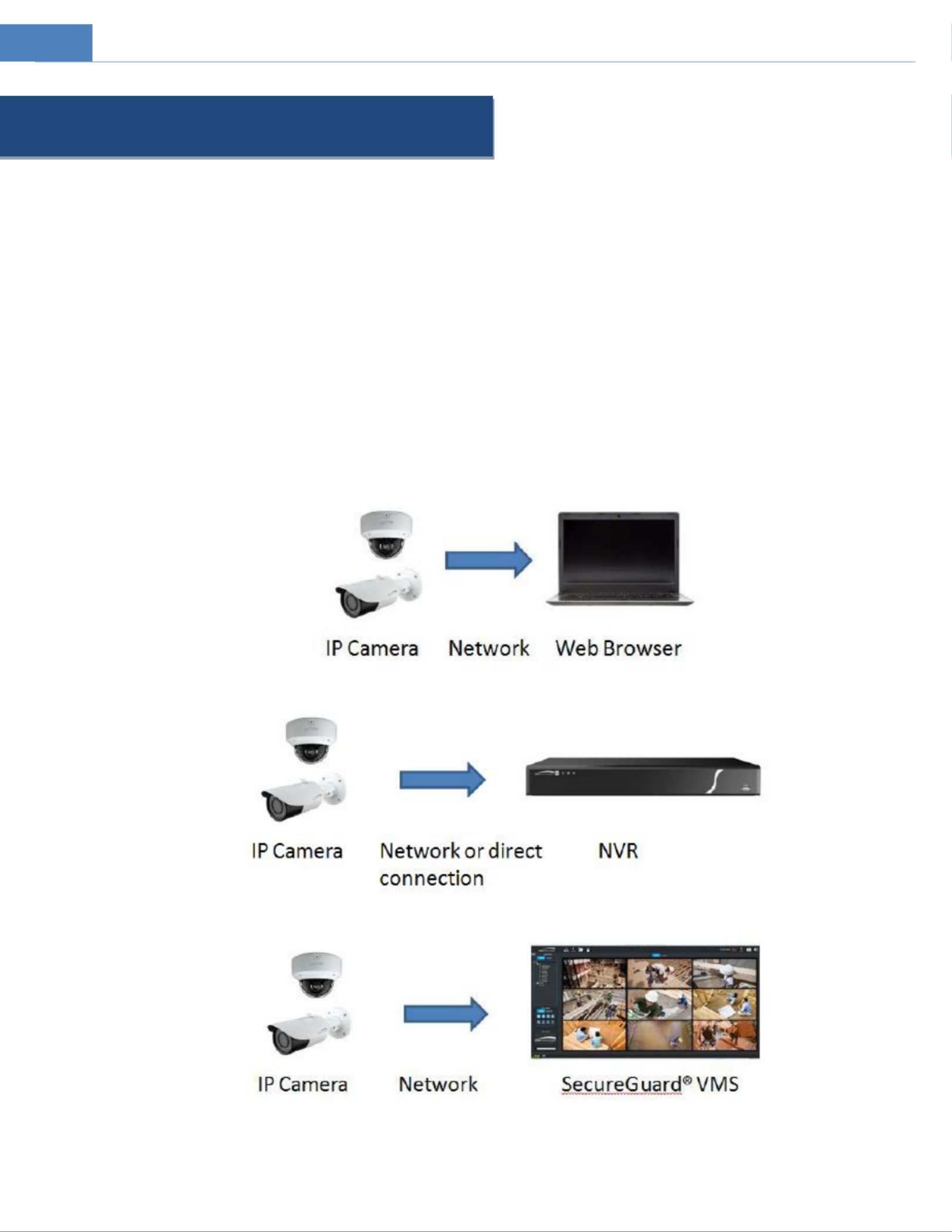
Remote viewing support via web browser, mobile APP, and CMS/VMS
Applications
3
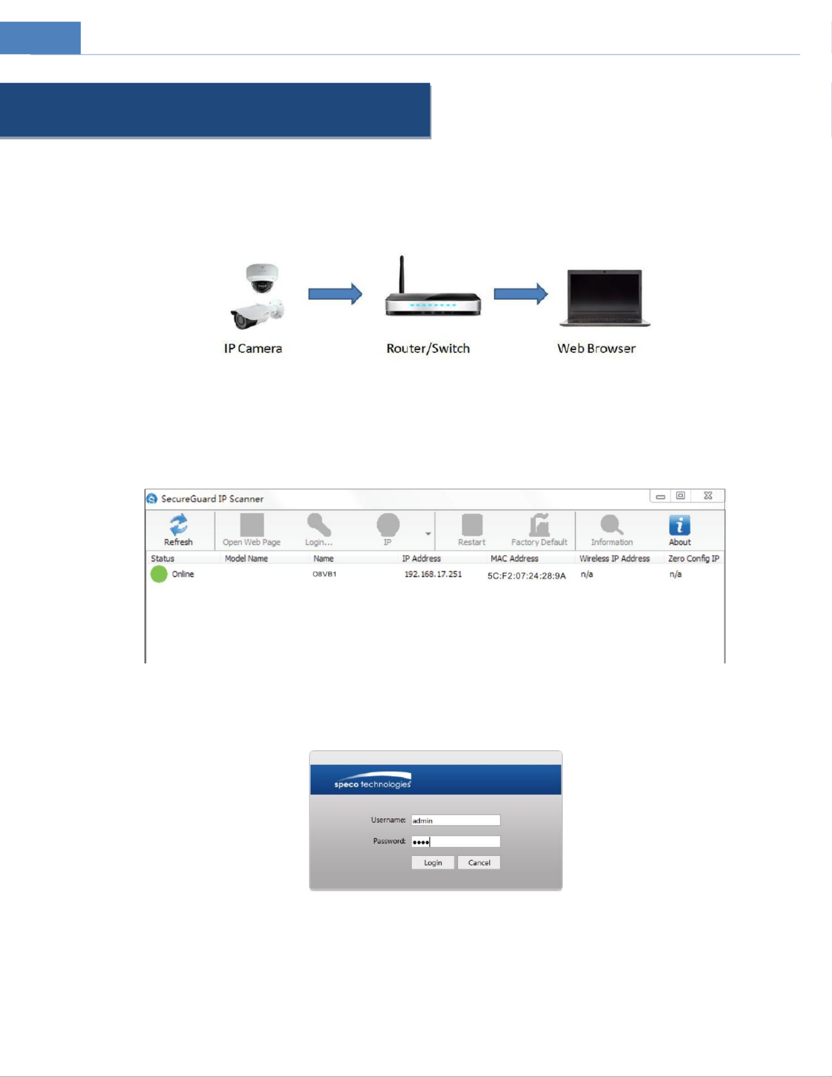
2 Web Access and Login
The IP camera settings can be accessed via a web browser through the LAN.
Access through IP Scanner
Network connection:
①Make sure the PC and IP-Cam are connected on the same local network. The camera is set to DHCP by default and will be
assigned an IP address by the DHCP server. Make sure that the local network has a DHCP server. Routers typically have a DHCP
server built in.
② Install IP Scanner from the CD and run it after installation. IP Scanner is the tool for discovering the IP cameras on the local
network.
③ In the device list, the IP address, model number, and MAC address of each device will be listed. Select the applicable
device and double click to open up the web viewer. You can also manually enter the IP address in the address bar of the web
browser.
The login interface is shown above. Default user name is admin and password is 1234. After logging in, follow directions to install applicable
plug-ins for viewing video.

4
3 Live View
The window below will be shown after logging in.
The following table describes the icons on the live view interface
Icon
Description
Icon
Description
Original size of resolution
Start/stop local recording
Fit (correct scale)
Zoom/Focus control (for motorized
models)
Auto (fill the window)
SD card recording indicator
Full screen (show video only)
Abnormal clarity indicator
Start/stop live view
Scene change indicator
Enable/disable audio
Line crossing indicator
Snapshot
Intrusion indicator
Zoom in (for motorized models)
Motion alarm indicator
Zoom out (for motorized
models)
All indicator icons above will flash in live view interface only when the corresponding events are enabled.
In full screen mode, to exit, double click on the mouse or press the ESC key on the keyboard.
Click the zoom/focus control button to show the control panel. The descriptions of the control panel are as follows:

5
Icon
Description
Icon
Description
Zoom -
Zoom +
Focus -
Focus +
One key focus (used when image is out of focus after manual adjustment)

7
4.1.3 Local Recording
Go to System Local Recording to set up the storage path of captured pictures and recorded videos on the local PC There is .
also an option to enable or disable the bitrate display in the recorded files.
For the model with built-in MIC, there is also an option to enable or disable audio recording.
4.1.4 Storage
Go to System Storage to go to the interface as shown below.
SD Card Management
When the card is used for the first time, c format the SD card. lick the “Format” buon to All data on the card will be cleared
by clicking this button.
Click the “ ”Eject button to stop writing data to the SD card. Then the SD card can be ejected safely.
Snapshot Quota: Set the capacity proportion of captured pictures on the SD card.
Video Quota: Set the capacity proportion of record files the SD card. on
Schedule Recording Settings
1. Go to Storage Record to go to the interface as shown below.

8
2. Set record stream, pre-record time and cycle writing.
Pre Record Time: Set the time to record before the actual recording begins.
3. Set schedule r ing. C edule. ecord heck “Enable Schedule Record” and set the sch
Week schedule ly
Set the alarm time from Monday to Sunday for a single week Each day is divided in one hour increments. Green means .
scheduled. Blank means unscheduled.
“Add”: Add the schedule for a special day. Drag the mouse to set the time on the timeline.
“Erase”: Delete the schedule. Drag the mouse to erase the time on the timeline.
Manual Input: Click it r a specific day to enter specific start and end times. This adds more granularit (minutes). fo ies
Day schedule
Set the alarm time for alarm a special day, such as holiday. a
Note: Holiday schedule takes priority over w schedule. eekly
Snapshot Settings
Go System Storage Snapshot to go to the interface as shown below. to

9
Set the format, resolution and quality of the image saved the SD card and the snapshot interval and quantity the on and
timing snapshot here.
Snapshot Quantity: The number you set here is the maximum quantity of snapshots. The actual quantity of snapshots may be
less than this number. Supposing the occurrence time of an alarm event is less than the time capturing pictures the actual of ,
quantity of snapshots is less than the set quantity of snapshots.
Timing Snapshot: Enable timing snapshot first and then set the snapshot interval and schedule. The setup steps of schedule
are the same as the schedule recording (See Schedule Recording).
4.2 Video Configuration
Video Configuration includes Image Settings Video/Audio Setup, D, Privacy Mask and Region of Interest. , OS
4.2.1 Image Configuration
In the Image Settings interface as shown below, various settings can be adjusted, such as brightness, contrast, hue and
saturation and so on. The common mode and day and night mode can be set up separately. The image effect can be quickly
viewed by switching the configuration file.
Brightness: Set the brightness level of the camera’s image.
Contrast: Set the color difference between the brightest and darkest parts.
10
Hue: Set the total color degree of the image.
Saturation: Set the degree of color purity. The purer the color is, the brighter the image is.
WDR: WDR can adjust the camera to provide a better image when there are both very bright and very dark areas
simultaneously in the field of the view by lowering the brightness of the bright area and increasing the brightness of the dark
area. Recording will be stopped for a few seconds while the mode is changing from non-WDR to WDR mode.
Sharpness: Set the resolution level of the image plane and the sharpness level of the image edge.
Noise Reduction: Decrease the noise and make the image more thorough. Increasing the value will make the noise reduction
effect better but it will reduce the image resolution.
Defog: Activating this function and setting an appropriate value as needed in foggy, dusty, smoggy or rainy environment to
get clear images.
Backlight Compensation:
Off: disables the backlight compensation function. It is the default mode.
HLC: lowers the brightness of the entire image by suppressing the brightness of the image s bright area and reducing the ’
size of the halo area.
BLC: If enabled, the auto exposure will activate according to the scene so that the object of the image in the darkest area
will be seen clearly.
Antiflicker:
Off: disables the anti-flicker function. This is used mostly in outdoor installations.
50Hz: reduces flicker in 50Hz lighting conditions.
60Hz: reduces flicker in 60Hz lighting conditions.
White Balance : Adjust the color temperature according to the environment automatically.
Frequency: 50Hz and 60Hz can be optional.
Day/night Mode: Please choose the mode as needed.
Sensitivity: High, middle and low can be selected for switching back and forth from day to night modes.
Infrared Mode: C hoose “ON”, “OFF” and “Auto”.
Exposure Mode: C If manual is chosen, the digital shutter speed can be adjusted. hoose “Auto” or “Manual”.
Gain Limit: The higher the gain value is, the higher the brightness of the image is and the more noises of the image are.
Image Mirror: Turn the current video image horizontally.
Image Flip: Turn the current video image vertically.
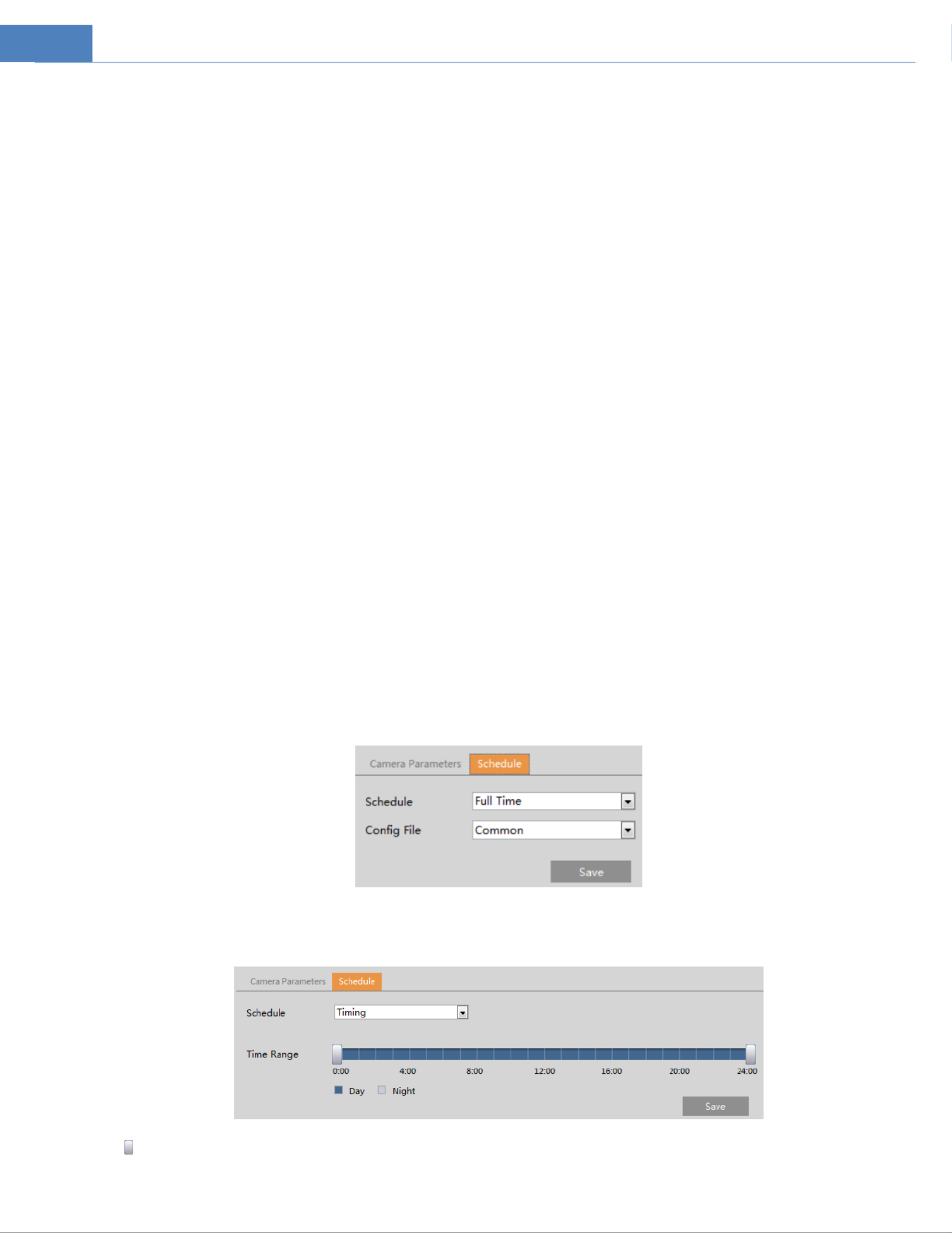
Schedule Settings of Image Parameters:
Click the “Schedule” tab as shown below.
Set full time schedule for common, day Timingor night mode and specied me schedule for day and night. Choose “ ” in the
drop-down box of schedule as shown below.
Drag “ ” icons to set the me of day and night. Blue means day me and blank means night me. If the current mode of
camera parameters is set to Timing , the image configuration mode will automatically switch between day and night “ ”

11
according to the schedule.
4.2.2 Video / Audio Configuration
Go to Image Video / Audio interface as shown below. In this interface, set the resolution, frame rate, bitrate type, video
quality and so on subject to the actual network condition.
Click the “Audio” tab to go to the interface as shown below.
Three video streams can be adjustable.
Resolution: The size of image.
Frame rate: The higher the frame rate, the video is smoother.
Bitrate type: CBR and VBR are optional Bitrate is related to image quality. CBR means that no matter how much change is .
seen in the video scene, the compression bitrate will be kept constant. VBR means that the compression bitrate will be
adjusted according to scene changes For example, for scenes that do not have much movement, the bitrate will be kept at a .
lower value. This can help optimize the network width usage. band
Bitrate: it can be adjusted when the mode is set to CBR. The higher the bitrate, the better the image quality will be.
Video Quality: It can be adjusted when the mode is set to VBR. The higher the image quality, the more bitrate will be
required.
I Frame interval: It determines how many frames are allowed between a “group of pictures”. When a new scene begins in a
video, until that scene ends, the entire group of frames (or pictures) can be considered as a group of pictures. If there is not
much movement in the scene, setting the value higher than the frame rate is fine, potentially resulting in less bandwidth
usage. However, if the value is set too high, and there is a high frequency of movement in the video, there is a risk of frame
skipping.
Video Compression: H264 or H265 can be optional If H.265 is chosen, make sure the client system is able to decode H.265..
Profile: For H.264. Baseline, main and high profiles are selectable.
Send Snapshot: How many snapshots to generate for an event.
Video encode slice split: I this function is enabled, smooth image can be gotten en though using the low-performance PC. f ev
Watermark: When playing back the local recorded video in the search interface, the watermark can be displayed. To enable it,
check the watermark box and enter the watermark text.
Audio Encoding: G711A and G711U are selectable.
Audio Type: LIN. Some models may support MIC type.
4.2.3 OSD Configuration
Go to Video OSD interface as shown below.

12
Set time stamp, device name OSD content and picture overlap here. After enabling the corresponding display and entering ,
the content, drag them to change their position. Then c lick the “Save” buon to save the sengs.
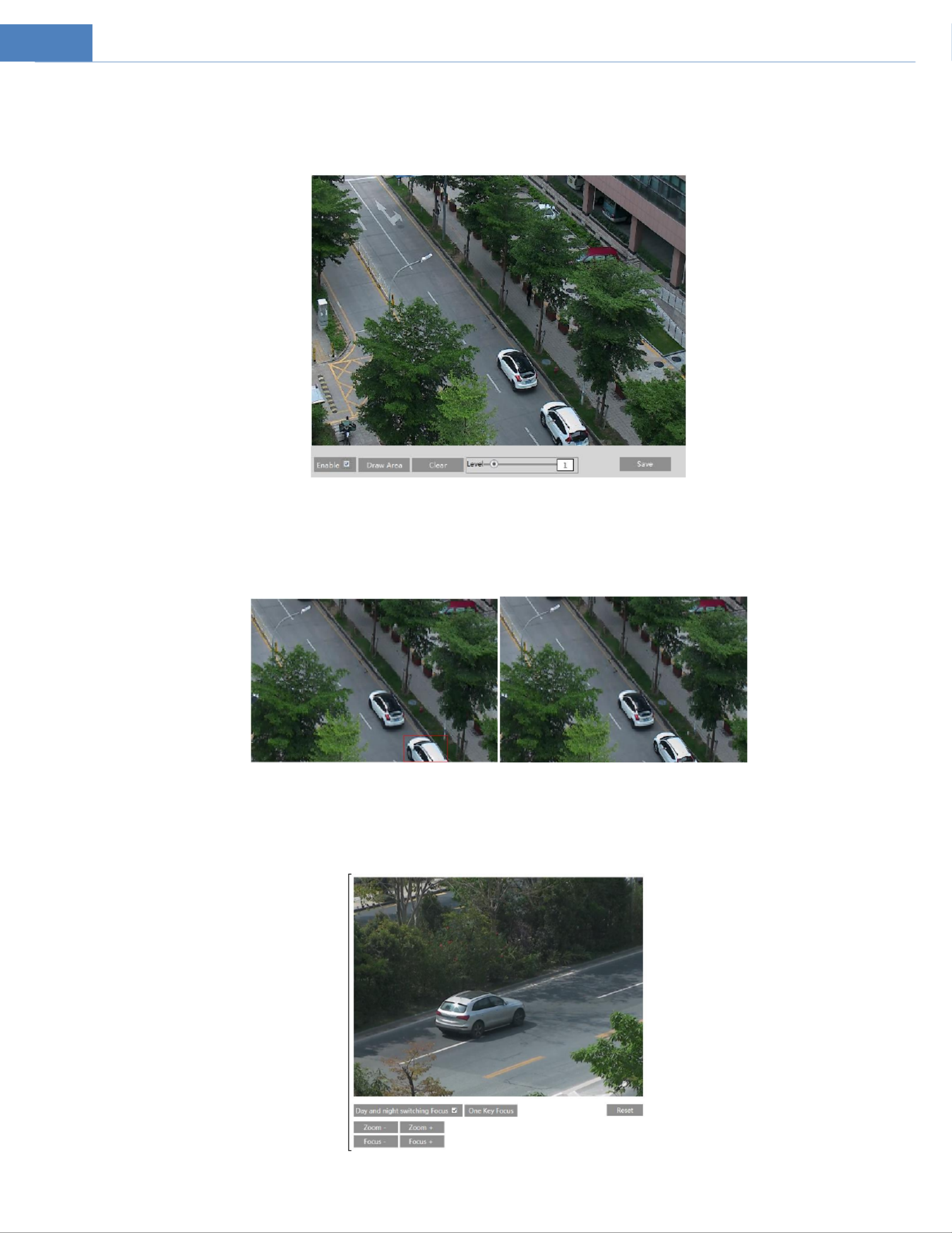
4.2.4 Video Mask
Go to Image Video Mask interface as shown below. A maximum of 4 zones can be set up.
To set up video mask:
1. Enable video mask.
2. Click the “Draw Area” buon and then drag the mouse to draw the video mask area.
3. Click the “Save” buon to save the sengs.
4. Return to the live to verify that the area have been drawn as shown as blocked out in the image.
To clear the video mask:
Click the “Clear” buon to delete the current video mask area.
13
4.2.5 ROI Configuration
Go to Image ROI Config interface as shown below. An area in the image can be set as a region of interest. This area will have
a higher bitrate than the rest of the image, resulting in better image quality for the identified area.
1. Check “Enable” and then click “Draw Area” buon.the
2. Drag the mouse to set the ROI area.
3. Set the level.
4. Click the “Save” buon to save the sengs.
4.2.6 Zoom/Focus
This function is only available for the model with motorized zoom lens. Within this section, zoom and focus can be
controlled. If the image is out of focus after a manual adjustment, one key focus can be used to set the focus automatically.
14
4.3 Event Setup
4.3.1 Motion Detection
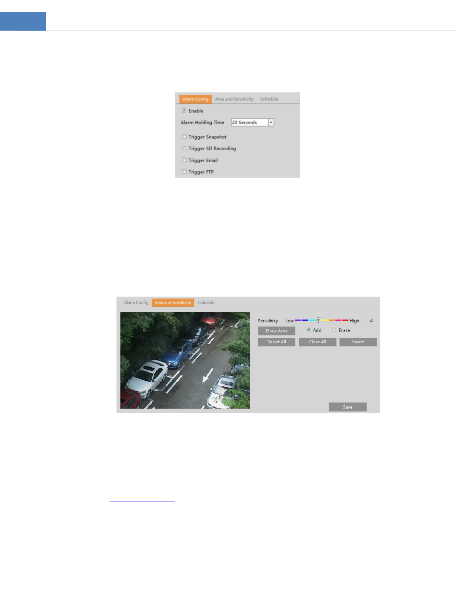
Go to Event Setup Motion Detection to set motion detection alarm.
1. s. If unchecked, the camera will not send out any signals to trigger Check “Enable” check box to acvate moon based alarm
motion-based recording to the NVR or CMS, even if there is motion in the video.
Trigger Snapshot: If selected, the system will capture images on motion detection and save the images on an SD card.
Trigger SD Recording: If selected, video will be recorded on an SD card on motion detection.
Trigger Email: If mail ttach Picture are checked (email address must be set first in the ail configuration “Trigger E ” and “A ” Em
interface), the captured pictures and triggered event will be sent into those addresses.
Trigger FTP: If are checked, the captured pictures will be sent into FTP server address. “Trigger FTP” and “Aach Picture”
Please refer to FTP configuration chapter for more details.
2. Set motion detection area and sensitivity. go to the interface as shown below Click the “Area and Sensivity” tab to .
Move the “Sensivity” scroll bar to set the sensitivity. Higher sensitivity value means that motion will be triggered more
easily.
Select rag the mouse to draw drag the mouse to clear “Add” and click “Draw”. D the moon detecon area; Select “Erase” and
motion detection area.
After that, click the Clear All can be used to clear out the entire motion zone. “Save” to save the sengs. “ ”
3. Set the schedule for motion detection. The schedule setup steps the motion detection are the same as the schedule of
recording setup (See Schedule Recording).
4.3.2 Other Alarms
SD Card Full
1. Go to Event Setup Anomaly SD Card Full.

15
2. Enable and set the alarm holding time. Click “ ”
3. Set alarm trigger options. Trigger Email and FTP. The setup steps are the same motion detection. Please refer to motion as
detection chapter for details.
SD Card Error
When there are some errors in writing to SD card, the corresponding alarms will be triggered.
1. Go to Event Setup Anomaly SD Card Error as shown below.
2. Click “Enable” and set the alarm holding me.
3. Set alarm trigger options. Trigger Email and FTP. The setup steps are the same motion detection. Please refer to as motion
detectionchapter for details.
4.3.3 Alarm Server
Go to Alarm Alarm Server interface as shown below.
Set the server address, port, heartbeat and heartbeat interval. When an alarm occurs, the camera will transfer the alarm
event to the alarm server. If an alarm server is not needed, there is no need to configure this sectio n.
4.4 Analytics Configuration
This series of IP cameras supports certain smart functions, such as line crossing detection, region intrusion detection, etc.
These events can be triggered as alarm events.
For more accuracy, here are some recommendations for installation.
Cameras should be installed on stable surfaces as vibrations can affect the accuracy of detection. ,
Avoid pointing the camera at the reflective surfaces (like shiny floors, mirrors, glass, lake surfaces and so on).
Avoid places that are narrow or have too much shadowing.
Avoid scenario where the object color is similar to the background color. ’s
At any time of day or night, please make sure the image of the camera is clear and with adequate and even light,
avoiding overexposure or too much darkness on both sides.

16
4.4.1 Abnormality
This function can detect changes in the surveillance environment affected by the external factors.
Go to Analytics Abnormality interface as shown below.
1. Enable the . applicable detecon that’s desired
Video Blur Detection: Alarms will be triggered if the video becomes blurry.
2. Set the alarm holding time and alarm trigger options. The setup steps are the same motion detection. Please refer to as
motion detection chapter for details.
3. Click “Save” buon to save the settings.
4. Set the sensivity of the excepon detecon. Click “Sensivity” tab to go to the interface as shown below.
Drag the slider to set the sensitivity value or directly enter the sensivity value in the textbox. Click “Save” buon to save the
settings.
The sensitivity value of Video Blur Detection: The higher the value is, the more sensitive the system responds to the
blurriness of the image.
※
※
※
※※The requirements of camera and surrounding area
1. Auto-focusing function should not been enabled for exception detection.
2. Try not to enable exception detection when light changes greatly in the scene.
4.4.2 Line Crossing
Line Crossing: Alarms will be triggered if the target crosses the defined alarm lines.
Go to Analytics Line Crossing interface as shown below.
1. Enable line crossing alarm and set the alarm holding time.
Specyfikacje produktu
| Marka: | Speco Technologies |
| Kategoria: | Kamera monitorująca |
| Model: | O8VT1 |
Potrzebujesz pomocy?
Jeśli potrzebujesz pomocy z Speco Technologies O8VT1, zadaj pytanie poniżej, a inni użytkownicy Ci odpowiedzą
Instrukcje Kamera monitorująca Speco Technologies

12 Stycznia 2025
12 Stycznia 2025
11 Stycznia 2025
22 Września 2024
20 Września 2024
20 Września 2024
18 Września 2024
18 Września 2024
18 Września 2024
18 Września 2024
Instrukcje Kamera monitorująca
- Kamera monitorująca Sony
- Kamera monitorująca Samsung
- Kamera monitorująca Tenda
- Kamera monitorująca Motorola
- Kamera monitorująca Stabo
- Kamera monitorująca Logitech
- Kamera monitorująca Xiaomi
- Kamera monitorująca Braun
- Kamera monitorująca Pioneer
- Kamera monitorująca TP-Link
- Kamera monitorująca Philips
- Kamera monitorująca Bosch
- Kamera monitorująca Gigaset
- Kamera monitorująca Hikvision
- Kamera monitorująca EZVIZ
- Kamera monitorująca Conceptronic
- Kamera monitorująca Panasonic
- Kamera monitorująca Canon
- Kamera monitorująca Crestron
- Kamera monitorująca Withings
- Kamera monitorująca Asus
- Kamera monitorująca Nedis
- Kamera monitorująca AG Neovo
- Kamera monitorująca Reolink
- Kamera monitorująca Boss
- Kamera monitorująca TRENDnet
- Kamera monitorująca Marquant
- Kamera monitorująca Toshiba
- Kamera monitorująca D-Link
- Kamera monitorująca August
- Kamera monitorująca Niceboy
- Kamera monitorująca Ring
- Kamera monitorująca Garmin
- Kamera monitorująca Imou
- Kamera monitorująca Blaupunkt
- Kamera monitorująca Grundig
- Kamera monitorująca APC
- Kamera monitorująca Honeywell
- Kamera monitorująca BLOW
- Kamera monitorująca Manhattan
- Kamera monitorująca Strong
- Kamera monitorująca Swann
- Kamera monitorująca Kwikset
- Kamera monitorująca Kodak
- Kamera monitorująca Cisco
- Kamera monitorująca ORNO
- Kamera monitorująca Broan
- Kamera monitorująca Moxa
- Kamera monitorująca Synology
- Kamera monitorująca Gembird
- Kamera monitorująca ZTE
- Kamera monitorująca Turing
- Kamera monitorująca Lindy
- Kamera monitorująca Minox
- Kamera monitorująca Zebra
- Kamera monitorująca DSC
- Kamera monitorująca JVC
- Kamera monitorująca ZyXEL
- Kamera monitorująca Trust
- Kamera monitorująca LogiLink
- Kamera monitorująca Furrion
- Kamera monitorująca Linksys
- Kamera monitorująca Google
- Kamera monitorująca Digitus
- Kamera monitorująca Vimar
- Kamera monitorująca V-TAC
- Kamera monitorująca Dahua Technology
- Kamera monitorująca Schneider
- Kamera monitorująca Eufy
- Kamera monitorująca Ricoh
- Kamera monitorująca Emos
- Kamera monitorująca AVMATRIX
- Kamera monitorująca Renkforce
- Kamera monitorująca Rollei
- Kamera monitorująca Marshall
- Kamera monitorująca Perel
- Kamera monitorująca Somfy
- Kamera monitorująca Uniden
- Kamera monitorująca Netgear
- Kamera monitorująca Thomson
- Kamera monitorująca DiO
- Kamera monitorująca Velleman
- Kamera monitorująca Ferguson
- Kamera monitorująca DataVideo
- Kamera monitorująca Delta Dore
- Kamera monitorująca Pyle
- Kamera monitorująca Intellinet
- Kamera monitorująca CRUX
- Kamera monitorująca Setti+
- Kamera monitorująca Waeco
- Kamera monitorująca Vivotek
- Kamera monitorująca Vtech
- Kamera monitorująca EtiamPro
- Kamera monitorująca Edimax
- Kamera monitorująca Petcube
- Kamera monitorująca ION
- Kamera monitorująca First Alert
- Kamera monitorująca AirLive
- Kamera monitorująca Maginon
- Kamera monitorująca EnGenius
- Kamera monitorująca SPC
- Kamera monitorująca Planet
- Kamera monitorująca Brilliant
- Kamera monitorująca Genie
- Kamera monitorująca LevelOne
- Kamera monitorująca Axis
- Kamera monitorująca Sanyo
- Kamera monitorująca Lorex
- Kamera monitorująca Control4
- Kamera monitorująca Milesight
- Kamera monitorująca Aluratek
- Kamera monitorująca Abus
- Kamera monitorująca Elro
- Kamera monitorująca Olympia
- Kamera monitorująca Hama
- Kamera monitorująca Marmitek
- Kamera monitorująca Ubiquiti Networks
- Kamera monitorująca Western Digital
- Kamera monitorująca Netatmo
- Kamera monitorująca Schwaiger
- Kamera monitorująca Promise Technology
- Kamera monitorująca GVI Security
- Kamera monitorująca AVer
- Kamera monitorująca ZKTeco
- Kamera monitorująca Netis
- Kamera monitorująca Extech
- Kamera monitorująca Denver
- Kamera monitorująca Anker
- Kamera monitorująca Allnet
- Kamera monitorująca Marshall Electronics
- Kamera monitorująca Orion
- Kamera monitorująca Yale
- Kamera monitorująca SereneLife
- Kamera monitorująca Ernitec
- Kamera monitorująca AVerMedia
- Kamera monitorująca MEE Audio
- Kamera monitorująca Genius
- Kamera monitorująca Trevi
- Kamera monitorująca Technaxx
- Kamera monitorująca Atlona
- Kamera monitorująca Hanwha
- Kamera monitorująca Overmax
- Kamera monitorująca Quantum
- Kamera monitorująca Y-cam
- Kamera monitorująca Grandstream
- Kamera monitorująca Raymarine
- Kamera monitorująca Powerfix
- Kamera monitorująca Avanti
- Kamera monitorująca Ikan
- Kamera monitorująca Alecto
- Kamera monitorująca Avidsen
- Kamera monitorująca JUNG
- Kamera monitorująca Burg Wächter
- Kamera monitorująca Foscam
- Kamera monitorująca Lumens
- Kamera monitorująca Monacor
- Kamera monitorująca Dörr
- Kamera monitorująca M-e
- Kamera monitorująca EVE
- Kamera monitorująca Smartwares
- Kamera monitorująca Adj
- Kamera monitorująca Qian
- Kamera monitorująca Arenti
- Kamera monitorująca Elmo
- Kamera monitorująca Vitek
- Kamera monitorująca Alfatron
- Kamera monitorująca UniView
- Kamera monitorująca Clas Ohlson
- Kamera monitorująca Laserliner
- Kamera monitorująca Megasat
- Kamera monitorująca REVO
- Kamera monitorująca BZBGear
- Kamera monitorująca BirdDog
- Kamera monitorująca KJB Security Products
- Kamera monitorująca HiLook
- Kamera monitorująca Profile
- Kamera monitorująca Aldi
- Kamera monitorująca Aritech
- Kamera monitorująca Acti
- Kamera monitorująca ACME
- Kamera monitorująca Flamingo
- Kamera monitorująca Caliber
- Kamera monitorująca Eminent
- Kamera monitorująca Sitecom
- Kamera monitorująca Exibel
- Kamera monitorująca Fortinet
- Kamera monitorująca KlikaanKlikuit
- Kamera monitorująca Trebs
- Kamera monitorująca Ednet
- Kamera monitorująca Steren
- Kamera monitorująca Flir
- Kamera monitorująca Buffalo
- Kamera monitorująca Arlo
- Kamera monitorująca Nest
- Kamera monitorująca Siedle
- Kamera monitorująca Hive
- Kamera monitorująca Switel
- Kamera monitorująca Chacon
- Kamera monitorująca InFocus
- Kamera monitorująca Hombli
- Kamera monitorująca Naxa
- Kamera monitorująca Konig
- Kamera monitorująca Valueline
- Kamera monitorująca BRK
- Kamera monitorująca QSC
- Kamera monitorująca Xavax
- Kamera monitorująca Vaddio
- Kamera monitorująca Gira
- Kamera monitorująca Interlogix
- Kamera monitorująca Boyo
- Kamera monitorująca IC Intracom
- Kamera monitorująca Iget
- Kamera monitorująca EverFocus
- Kamera monitorująca Adesso
- Kamera monitorująca Satel
- Kamera monitorująca POSline
- Kamera monitorująca Notifier
- Kamera monitorująca Hawking Technologies
- Kamera monitorująca Friedland
- Kamera monitorująca Nexxt
- Kamera monitorująca Monoprice
- Kamera monitorująca Watec
- Kamera monitorująca Beafon
- Kamera monitorująca Chuango
- Kamera monitorująca ETiger
- Kamera monitorująca Videcon
- Kamera monitorująca INSTAR
- Kamera monitorująca Provision ISR
- Kamera monitorująca Aqara
- Kamera monitorująca Advantech
- Kamera monitorująca Digital Watchdog
- Kamera monitorująca Ganz
- Kamera monitorująca AViPAS
- Kamera monitorująca ClearOne
- Kamera monitorująca Ebode
- Kamera monitorująca Oplink
- Kamera monitorująca Sonic Alert
- Kamera monitorująca Linear PRO Access
- Kamera monitorująca Summer Infant
- Kamera monitorująca SMC
- Kamera monitorująca Topica
- Kamera monitorująca Kogan
- Kamera monitorująca Iiquu
- Kamera monitorująca Verint
- Kamera monitorująca Brinno
- Kamera monitorująca Rostra
- Kamera monitorująca Caddx
- Kamera monitorująca Spyclops
- Kamera monitorująca EKO
- Kamera monitorująca Kguard
- Kamera monitorująca Woonveilig
- Kamera monitorująca Mobi
- Kamera monitorująca Surveon
- Kamera monitorująca Hollyland
- Kamera monitorująca Epcom
- Kamera monitorująca Indexa
- Kamera monitorująca Lutec
- Kamera monitorująca Whistler
- Kamera monitorująca ClearView
- Kamera monitorująca VideoComm
- Kamera monitorująca IMILAB
- Kamera monitorująca 3xLOGIC
- Kamera monitorująca Pelco
- Kamera monitorująca Leviton
- Kamera monitorująca Inkovideo
- Kamera monitorująca Pentatech
- Kamera monitorująca Weldex
- Kamera monitorująca SecurityMan
- Kamera monitorująca Canyon
- Kamera monitorująca CNB Technology
- Kamera monitorująca Tapo
- Kamera monitorująca Aigis
- Kamera monitorująca Exacq
- Kamera monitorująca Brickcom
- Kamera monitorująca Laxihub
- Kamera monitorująca Securetech
- Kamera monitorująca EFB Elektronik
- Kamera monitorująca NetMedia
- Kamera monitorująca Videotec
- Kamera monitorująca Illustra
- Kamera monitorująca Nivian
- Kamera monitorująca E-bench
- Kamera monitorująca Syscom
- Kamera monitorująca Tecno
- Kamera monitorująca Night Owl
- Kamera monitorująca Guardzilla
- Kamera monitorująca Astak
- Kamera monitorująca Blink
- Kamera monitorująca Milestone Systems
- Kamera monitorująca Zavio
- Kamera monitorująca Campark
- Kamera monitorująca IPX
- Kamera monitorująca Dedicated Micros
- Kamera monitorująca Hamlet
- Kamera monitorująca Annke
- Kamera monitorująca AVTech
- Kamera monitorująca Qoltec
- Kamera monitorująca Approx
- Kamera monitorująca Digimerge
- Kamera monitorująca Wisenet
- Kamera monitorująca Infortrend
- Kamera monitorująca Epiphan
- Kamera monitorująca Mach Power
- Kamera monitorująca Compro
- Kamera monitorująca Aida
- Kamera monitorująca Ikegami
- Kamera monitorująca Accsoon
- Kamera monitorująca Vimtag
- Kamera monitorująca Gewiss
- Kamera monitorująca Alula
- Kamera monitorująca Insteon
- Kamera monitorująca Costar
- Kamera monitorująca ALC
- Kamera monitorująca Security Labs
- Kamera monitorująca Comtrend
- Kamera monitorująca Seneca
- Kamera monitorująca Avigilon
- Kamera monitorująca American Dynamics
- Kamera monitorująca Vosker
- Kamera monitorująca Sentry360
- Kamera monitorująca Bea-fon
- Kamera monitorująca Owltron
- Kamera monitorująca Enabot
- Kamera monitorująca Luis Energy
- Kamera monitorująca Sir Gawain
- Kamera monitorująca VisorTech
- Kamera monitorująca Atlantis Land
- Kamera monitorująca B & S Technology
- Kamera monitorująca I3International
- Kamera monitorująca IDIS
- Kamera monitorująca Ecobee
- Kamera monitorująca Conbrov
- Kamera monitorująca HuddleCamHD
- Kamera monitorująca Mobotix
- Kamera monitorująca IOIO
- Kamera monitorująca BIRDFY
- Kamera monitorująca I-PRO
- Kamera monitorująca DVDO
- Kamera monitorująca TCP
- Kamera monitorująca Bolin Technology
- Kamera monitorująca Nextech
Najnowsze instrukcje dla Kamera monitorująca
28 Stycznia 2025
25 Stycznia 2025
17 Stycznia 2025
17 Stycznia 2025
15 Stycznia 2025

13 Stycznia 2025

13 Stycznia 2025
13 Stycznia 2025

12 Stycznia 2025
12 Stycznia 2025