Instrukcja obsługi Speco Technologies D16WDS
Przeczytaj poniżej 📖 instrukcję obsługi w języku polskim dla Speco Technologies D16WDS (100 stron) w kategorii Kamera monitorująca. Ta instrukcja była pomocna dla 4 osób i została oceniona przez 2 użytkowników na średnio 4.5 gwiazdek
Strona 1/100

User ’s Guide (Ver. 1.6)
Models: Desktop - D8DS/D S 16D
Wall Mount - D8WDS/D16WDS
8/16 Channel Digital Video Recorder with 960H Resolution
About This User’s Guide
Before operating the unit, please read this thoroughly and retain it for future reference. user‟s guide
2
Cautions
Explanation of Graphical Symbols
WARNING
To reduce a risk of re or electric shock, do not expose this product to rain or moisture.
CAUTION
Changes or modications not approved by the manufacture will void the warranty of the product.
Using an incompatible battery may increase the risk of re or explosion.
Replace only with the same or equivalent type battery recommended by the manufacture.
Discard used batteries according to manufacturer‟s instructions.
This symbol indicates the presence of important operang and maintenance
(servicing) instrucons in the literature accompanying the product.
This symbol indicates the presence of “dangerous voltage” within the product’s
enclosure that may be of sucient magnitude to constute a risk of electric
shock, property damage, personal injury, or death.

3
These precautions MUST be followed for safety reasons
Warning
Do not use if the unit emits smoke.
Do not disassemble the unit.
Do not place any heavy or sharp objects on the unit.
Do not place on uneven surface.
Do not expose to shock or vibration.
Do not move the unit when the unit is powered on.
Do not block, and allow dust to accumulate in the air vents.
Do not restrict airow of the unit; doing so can damage the unit.
Only qualied and experienced personnel should perform installation and
servicing.
Turn off the power of the DVR when connecting Cameras, Audio or Sensor
Cables.
The manufacturer is not responsible for any damage caused by improper use
of the product or failure to follow instructions for the product.
The manufacturer is not responsible for any problems caused by or resulting
from the user physically opening the DVR for examination or attempting to
repair the unit.

4
Product Components
Please make sure the following components are included as specied below.
DVR Unit
Desktop: D8DS / D16DS
Wall Mount: D8WDS / D16WDS
Remote Control
Battery 1.5V (AAA x2)
Quick Setup Guide
Quick User Guide
USB Mouse
Software & Manual CD
Rack mount (x 2) & Screw ( x 6)
Adaptor
(DC12V 5A)
& AC Power cable (110V or 220V)
Audio Cable

5
Specifications
ITEM
D16DS/D16WDS
D8DS/D8WDS
Video
Input
Channel, Input Level
16CH Composite, 1.0Vp-p, 75ohm
8CH Composite, 1.0Vp-p, 75ohm
Signal Format
NTSC/PAL
Video Loss Check
Yes
Output
HDMI
1 HDMI (1280x720, 1920x1080)
VGA
1 VGA (1024x768, 1280x1024)
CVBS
1 BNC
SPOT
1 BNC
Audio
Input & Output
16 CH input & 1 CH output
8 CH input & 1 CH output
Audio Codec
G.711
Sensor/
Alarm
Sensor Input
4 (NC / NO Selectable)
Alarm Out
1 Alarm Out by Sensor, Motion and Video Loss
Record
Compression
H.264
Multi-operation
QUADPLEX (Playback/Record/Network/Backup)
Resolution
NTSC
960H
480fps
240fps
D1
480fps
240fps
CIF
480fps
240fps
PAL
960H
400fps
240fps
D1
400fps
240fps
CIF
400fps
240fps
Recording quality grade
LEVEL1 (L) ~ LEVEL5 (H)
Recording Mode
Continuous/Schedule/Motion/Manual/Sensor
Motion Detection
Motion detection setup by Grid
Recording by individual
channel s Resolution ’
Yes
Pre Recording
1 fps for up to 20minutes before an event
Post Recording
10 seconds to 3 minutes after an event
Display
Frame Rate (/Sec)
NTSC: 30fps/CH, 60 fields / PAL: 25fps/CH, 50 fields
Playback
Multi-Decoding
1, 4, 9, 16
1, 4, 8
Playback
Speed
Single channel
×2, 4, 8, 16, 32, 64
Multi-channels
×2, 4, 8, 16, 32
Search Mode
Timeline, Event, Archive, EZ Search, Log
Storage
HDD
Interface Type
Serial ATA
Max Capacity of
1 HDD
3 TB
Internal HDD
No.
2 (3: w/o DVDRW)

6
eSATA port
(Storage Extension)
1
USB Port
3 (Front - 2, Rear - 1)
3 (IR Board - 2, Main Board - 1)
Backup
USB Flash
Video & Still Image
Network
Video & Still Image
Huge Backup
Yes (up to 24 hours at a time)
User I/F
Menu Display
GUI
Input Method
Front buttons, Remote control, Mouse
RS- 485
PTZ control
1 - RS 485
Network
Dynamic DNS
Yes (Free DDNS)
Network Interface
10/100/1000 base-TX Ethernet (RJ- 45)
Max Network Streaming.
CIF 0fps/16CH 48
QCIF 480fps/16CH
CIF 240fps/8CH
QCIF 0fps/824 CH
Network
Access
Web Viewer (1:1)
Live, Search, Backup, Remote Setup, PTZ control
Mobile Phone Viewer (1:1)
Live, Search, PTZ control
Multi-sites Monitoring SW
Live, Search, Backup, Remote Setup, PTZ control
Features
DLS (Day Light Saving)
Yes
EZSearch
Thumbnail Preview
Time Stamp over AVI Backup
Yes
EZReco rd
Yes
EZSetup
Yes
EZNetwork
Yes
S.M.A.R.T
Yes
Digital Deterrent
Yes
Internal Beep
By Video Loss, HDD Error, S.M.A.R.T
Multi-Language
Yes
S/W Upgrade
USB Flash drive, Remote S/W Upgrade
NTP
Yes
Mac Viewer
Yes
Power Source
Power Supply Voltage
DC 12V 5A
Allowable operating temperature
5 - C, During storage: - - +50 C °C 40°10°C °
Allowable operation humidity
20 % - 80 %
Weight
Desktop Unit (Gross weight)
Approximately 11 lbs
Wall Mount (Gross Weight)
Approximately 16 lbs
Dimension
Desktop Unit (W x H x D)
14.90 x 13.38 x 2.” ” 83”
Wall Mount Unit (W x H x D)
13.5” x 17” x 3.5”
Please note that specications and unit exterior designs are subject to change without notication.

7
Table of Contents
1. Main Features ............................................................................................................................. 10
2. Initial Boot-up Process .................................................................................................................. 11
2-1. Initial Boot up and Basic Time Setup ........................................................................................ 11
2-2 Setting Daylight Saving Time . ................................................................................................... 11
2-3 Setting NTP (Network Time Protocol) . ....................................................................................... 12
3. Front and Rear Panels ................................................................................................................ 15
3-1. Front Panel .............................................................................................................................. 15
3-2. Rear Panel Connectors ............................................................................................................ 16
3-3. Remote Control ........................................................................................................................ 17
4. Setting up the DVR ...................................................................................................................... 18
4-1. Setup Main Live Screen –........................................................................................................ 18
4-2. Setup SYSTEM –..................................................................................................................... 19
4.2.1 EZ SETUP ............................................................................................................................. 22
4-3. Setup RECORD Mode –.......................................................................................................... 26
4-3-1. Recording Schedules ...................................................................................................... 28
4-4. Setup DEVICE Mode –............................................................................................................ 29
4-4-1. Alarm-Out ........................................................................................................................ 30
4-4-2. Digital Deterrent .............................................................................................................. 30
4-4-3. Keyboard Controller & PTZ Setup ................................................................................... 32
4-4-4. Spot Out .......................................................................................................................... 33
4-4-5. Motion Zone Setup .......................................................................................................... 34
4-5. Setup DISPLAY Mode –........................................................................................................... 35
4-6. Setup NETWORK Mode –.......................................................................................................36
4-6-1. Network Types ................................................................................................................ 37
4-6-2. DDNS ............................................................................................................................. 37
4-6-3. Network Port and Web Port ............................................................................................. 38
4-6-4. Network Stream .............................................................................................................. 38
4-7. Setup USER MANAGEMENT Mode –.....................................................................................39
4-8. Setup STORAGE Mode –........................................................................................................ 41
4-9. Setup - CONFIG Mode .............................................................................................................42
4-9-1. Firmware Upgrade .......................................................................................................... 43
5. Live, Search and Playback .......................................................................................................... 44
5-1. Live View ................................................................................................................................. 44
5-1-1. PTZ Control ....................................................................................................................49
5-2. Digital Zoom in Live and Playback Screen ............................................................................... 49
5-3. SEARCH Screen ...................................................................................................................... 50
5-3-1. EZSearch ........................................................................................................................ 51
5-3-2. Time Line Search ............................................................................................................ 52
5-3-3. Event Search .................................................................................................................. 52

8
5-3-4. Go To First Time .............................................................................................................. 53
5-3-5. Go To Last Time .............................................................................................................. 53
5-3-6. Go To Specic Time ........................................................................................................ 53
5-3-7. Archive List .....................................................................................................................53
5-3-8. Log List ........................................................................................................................... 54
5-4. Play Mode ................................................................................................................................ 54
6. Back Up .......................................................................................................................................... 55
6-1. Still Image Backup onto USB Flash Drive ................................................................................55
6-2. Video Backup onto USB Flash Drive during playback .............................................................. 56
6-3. EZCopy: Video Backup onto USB Flash Drive during playback ............................................... 57
6-4. Transferring Still Images or Video from the ARCHIVE List ........................................................ 58
6-5. Playback of Backup Video .......................................................................................................59
6-5-1. AVI Format ...................................................................................................................... 59
6-5-2. NSF Format .................................................................................................................... 60
7. Network Access Using the Multi-Sites Network Viewer ................................................................... 61
7-1. Overview .................................................................................................................................. 61
7-2. PC Requirements ..................................................................................................................... 61
7-3. Installation of the Program ....................................................................................................... 62
7-4. Live Window ............................................................................................................................63
7-4-1. Main User Interface ......................................................................................................... 63
7-4-2. Control Buttons ............................................................................................................... 63
7-5. Search and Playback Window .................................................................................................. 64
7-5-1. Main User Interface ......................................................................................................... 64
7-5-2. Main Control Panel ..........................................................................................................65
7-6. Setup of SpecoTech Multi Client ............................................................................................... 66
7-6-1. General ........................................................................................................................... 66
7-6-2. Event ..............................................................................................................................67
7-6-3. Record ............................................................................................................................ 68
7-6-4. Display ............................................................................................................................ 69
7-6-5. Language ........................................................................................................................ 70
7-6-6. About .............................................................................................................................. 70
7-7. Remote Setup .......................................................................................................................... 71
7-7-1. System ............................................................................................................................ 72
7-7-2. Record ............................................................................................................................ 73
7-7-3. Device ............................................................................................................................. 74
7-7-4. Display ............................................................................................................................ 75
7-7-5. Network ........................................................................................................................... 76
7-7-6. User Management ..........................................................................................................77
7-7-7. Storage ........................................................................................................................... 77
7-7-8. Remote Upgrade ............................................................................................................. 78
7-8. Operation ................................................................................................................................. 79

11
2. Initial Boot-up Process
2-1. Initial Boot up and Basic Time Set up
1. During the rst boot up, the following logo will be displayed.
2. After the logo, select the language and set date and time as specied below.
2-2 Setting Daylight Saving Time .
To enable Daylight Saving feature/NTP synchronization, take the following steps.
1. Enter the SETUP mode. The default Username is ADMIN “ ” and Password is “1111”.

12
2. Go to SETUP > SYSTEM > DATE & TIME SETUP
3. Select ON from the DAYLIGHT SAVING dropdown menu.
2-3 Setting NTP (Network Time Protocol) .
1. SETUP > SYSTEM > NTP SETUP > ON

14
MI
Michigan (W)
GMT- 6
GMT- 5
MN
Minnesota
GMT- 6
GMT- 5
MS
Mississippi
GMT- 6
GMT- 5
MO
Missouri
GMT- 6
GMT- 5
MT
Montana
GMT- 7
GMT- 6
NE
Nebraska
GMT- 6
GMT- 5
NE
Nebraska (W)
GMT- 7
GMT- 6
NV
Nevada
GMT- 8
GMT- 7
NH
New Hampshire
GMT- 5
GMT- 4
NJ
New Jersey
GMT- 5
GMT- 4
NM
New Mexico
GMT- 7
GMT- 6
NY
New York
GMT- 5
GMT- 4
NC
North Carolina
GMT- 5
GMT- 4
ND
North Dakota
GMT- 6
GMT- 5
ND
North Dakota (W)
GMT- 7
GMT- 6
OH
Ohio
GMT- 5
GMT- 4
OK
Oklahoma
GMT- 6
GMT- 5
OR
Oregon
GMT- 8
GMT- 7
OR
Oregon (E)
GMT- 7
GMT- 6
PA
Pennsylvania
GMT- 5
GMT- 4
RI
Rhode Island
GMT- 5
GMT- 4
SC
South Carolina
GMT- 5
GMT- 4
SD
South Dakota (E)
GMT- 6
GMT- 5
SD
South Dakota (W)
GMT- 7
GMT- 6
TN
Tennessee (E)
GMT- 5
GMT- 4
TN
Tennessee (W)
GMT- 6
GMT- 5
TX
Texas
GMT- 6
GMT- 5
TX
Texas (W)
GMT- 7
GMT- 6
UT
Utah
GMT- 7
GMT- 6
VT
Vermont
GMT- 5
GMT- 4
VA
Virginia
GMT- 5
GMT- 4
WA
Washington
GMT- 8
GMT- 7
WV
West Virginia
GMT- 5
GMT- 4
WI
Wisconsin
GMT- 6
GMT- 5
WY
Wyoming
GMT- 7
GMT- 6
NOTE: If you want the unit to automatically synchronize the local time, the Time Zone
must be properly set according to your local time zone.

15
3. Front and Rear Panels
3-1. Front Panel
DS Desktop Front
DS Wall Mount Front
Figure 1.1 Front panels 3. . DVR
Table 1.1. Front LED and Ports of Desktop Models (D16DS/D8DS) 3.
Name
Description
POWER
LED light is on when power is applied to the system.
HDD
LED light is on when the system is recording video data.
USB Port
This USB port for archiving footage into a USB device. (USB 2.0 connector)
Table 2 Front Buttons (D16DS/D8DS) 3.1. .
Name
Description
Buttons 1~16
Select a channel from CH1 to CH16
Buttons from 9 to 16 is used as function keys on PTZ control mode
To escape out of PTZ mode, press the ESC button.
MENU
Goes into the Setup window
COPY
Takes a Screenshot on Live View Goes into Backup during Playback and
ALARM
Activates the external alarm device
SEQ
Enables the sequence mode on Live
ESC
Exit the current mode or cancels current operation
PLAYBACK
Goes to search mode in
PTZ
Activates the Pan, Tilt and Zoom menu
MODE
Toggles between the available display modes (1x1, 2x2, 3x3, 4x4)
POWER
Will initiate system shut down
16
LIVE mode Moves U –p
SEARCH mode Skips 1min on playback and 1 frame on pause –ahead ahead
LIVE mode Moves Right –
SEARCH mode - Control the play speed (Fast Forward)
LIVE mode Moves Down –
SEARCH mode - Skips 1min back on playback and 1 frame back on pause
LIVE mode Moves Left –
SEARCH mode- Select the play s (Rewind) peed
LIVE mode Select (Center) –
SEARCH mode - Play & Pause
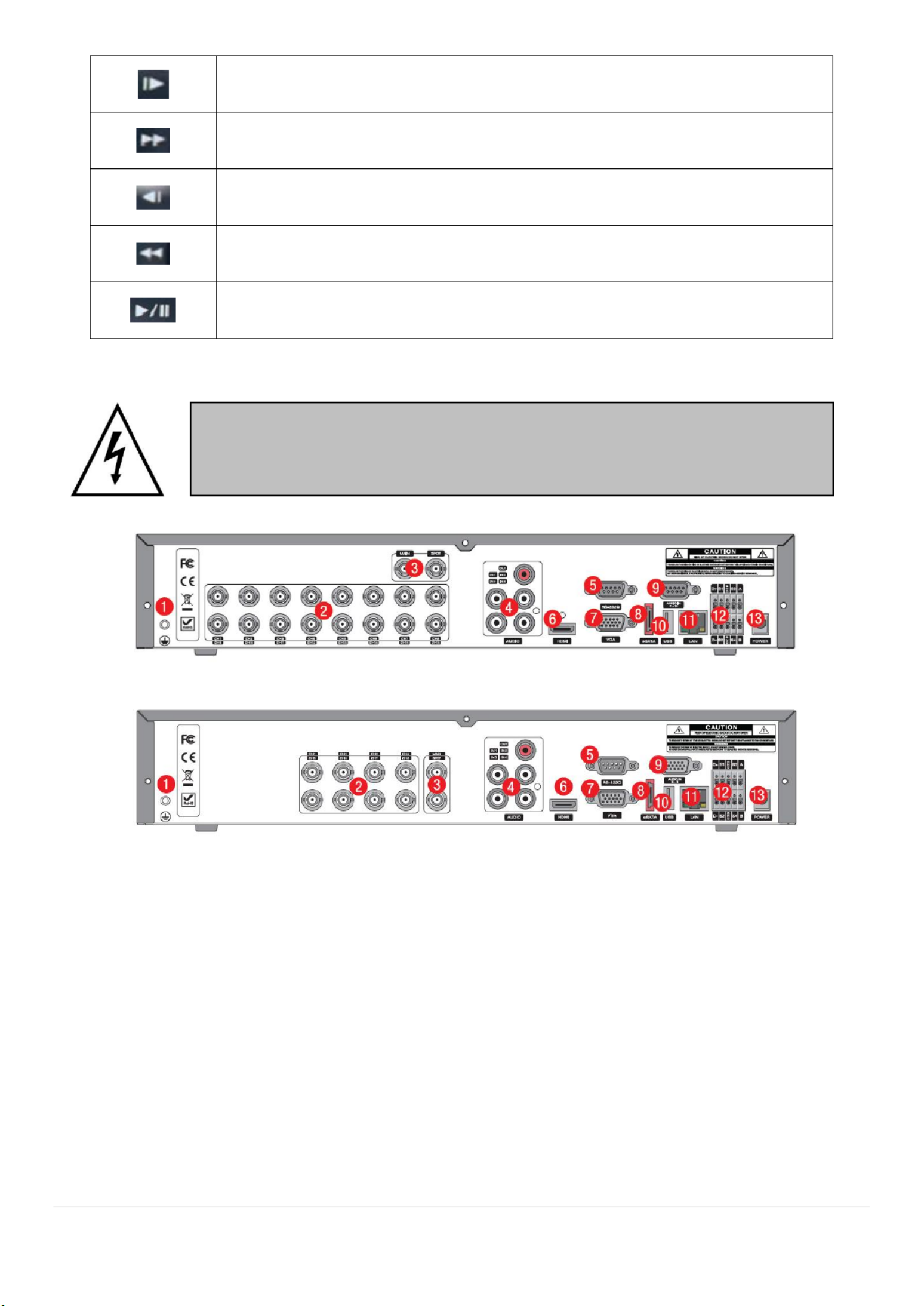
3-2. Rear Panel Connectors
D16 DS
D8DS
Figure 2 Connectors 3. .1.
① Ground: Use for ground port.
② VIDEO IN: Video input port.(For Analog & 960H cameras)
③ VIDEO OUT: MAIN Composite Video Output SPOT Spot Monitor –/ –
④ AUDIO IN & OUT: Four connectors for audio input connector for audio output. and one
⑤ RS- r engineering use only. 232C: Fo
⑥ HDMI: HDMI output port. Connectors to the HDMI Monitor
⑦ VGA: VGA (Video Graphics Array) output port. Connects to the PC VGA monitor.
⑧ E-SATA: External SATA port for extension storage.
⑨ AUDIO IN: Audio inputs connections for channels 5-8 or 5-16 through external cable
⑩ USB: USB terminal for video export or rmware upgrade
Do not power this system on before all the connections are attached.
Make sure all the connections are properly secured. Faulty connection may result in
the system being damaged.

18
4. Setting the DVR up
The following sections detail the initial setup of the . DVR
Menu screen will close if user response is not received in 5 minutes.
4-1. Setup Main Live Screen –
To enter the setup menu, right click on the mouse and select setup from the submenu or press the setup
button on the remote control.
Table 4.1.1 Live Screen and Quick Operation Window.
When the DVR prompts the LOG-IN window, enter the PASSWORD using the virtual keyboard, or the front
panel, or the remote control. The factory default password is 1111. It is highly recommended to assign a
new password to protect the system. User can assign a new password in SECURITY setup menu.
19
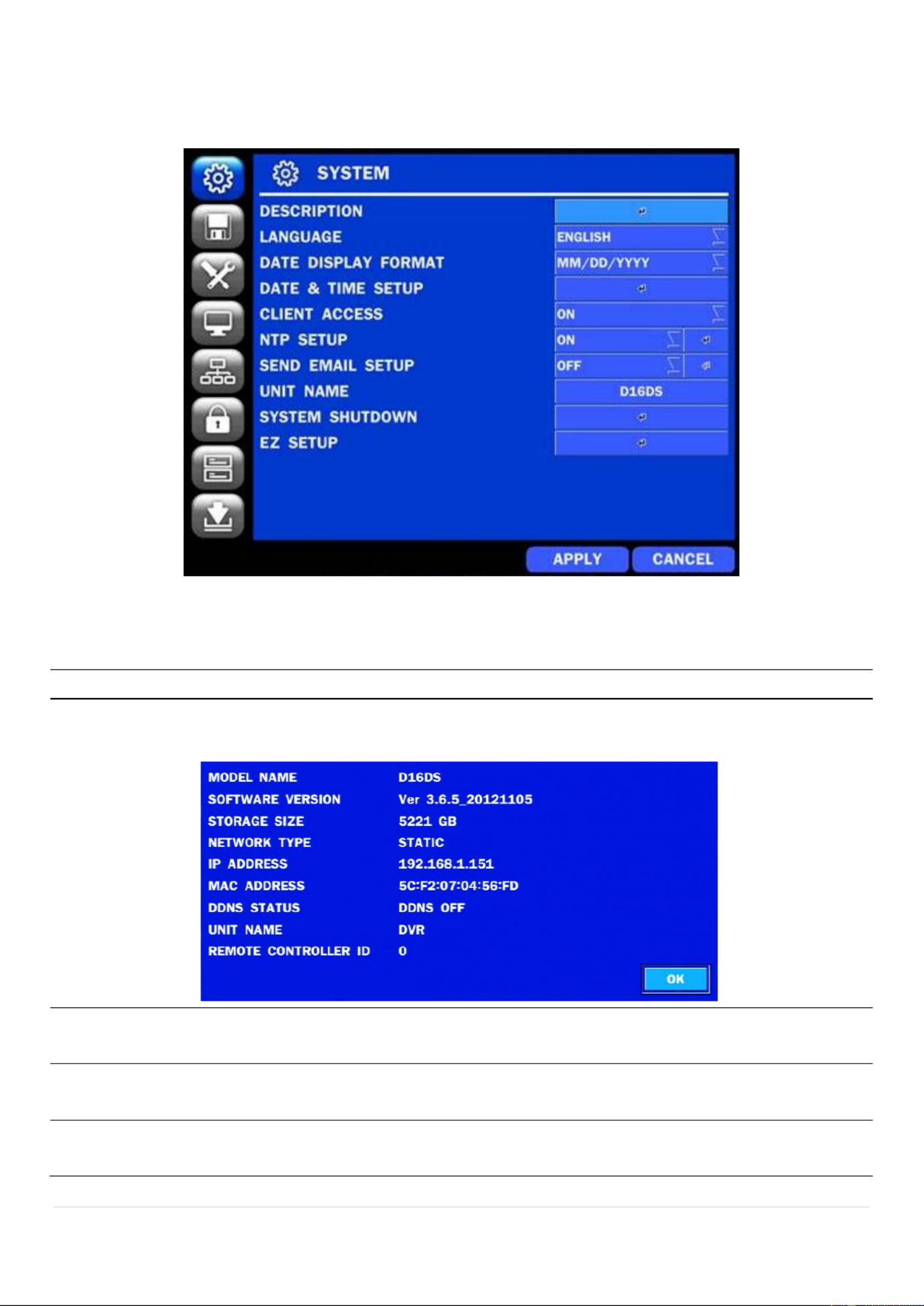
4-2. Setup SYSTEM –
In the SETUP menu, select the SYSTEM tab. Then, the SYSTEM menu is displayed as pictured below.
Navigate through the menu items using the mouse or the remote control and change the value of the menu.
Figure 4.2.1. SYSTEM Setup Screen
Table 4.2.1. Menu Items in SYSTEM Setup Screen
Item
Description
DESCRIPTION
Press the button to view the system information. (Software Version, Storage Size, IP
Address, MAC Address and DDNS Status)
LANGUAGE
Select the display language using the mouse or the remote control. Once a language is
selected, the display language will change.
DATE DISPLAY
FORMAT
Select the date display format using the mouse or the remote control. Options are:
MM/DD/YYYY, YYYY/MM/DD, DD/MM/YYYY, YYYY- -DD, MM- -YYYY, DD- -YYYYMM DD MM
DATE&TIME
SETUP
Select the display date and time using the mouse or the remote control and press OK
button to set the present date and time.

20
Select DAYLIGHT SAVING using the mouse o the remote control and select the r
appropriate daylight saving time zone. The available options are:
OFF: Daylight saving is turned o.
USA: Applies the USA daylight saving time.
EU: Applies the EU daylight saving time.
- Select the GMT AREA using the mouse or the remote control.
- Set the time dierence with the standard time using the mouse or the button.
OTHERS: If the time zone is neither USA nor EU, set the date and time of the daylight
saving period.
- Select BEGIN or END using the remote and press the SEL button.
Caution
- Do not set the start time to 23:00 for DLS.
- DLS cannot be applied if the date of BEGIN and END is the same.
CLIENT
ACCESS
Enable/Disable remote access through the network.
NTP
SETUP
NTP (Network Time Protocol) which synchronizes the time of the computer systems over
variable-latency data networks.
PRIMARY SNTP SERVER: Input the address of the primary NTP time-server.
SECONDARY SNTP SERVER: Input the address of the secondary NTP time-server.
TIME ZONE: NTP synchronizes with GMT (Greenwich Mean Time) regardless of
geography, user must set their own time difference.
CONNECTON MODE: Select the NTP time-server connection mode from TIME,
INTERVAL, and ONCE.
CONNECTION PERIOD
- Refresh the time at the designated time (e.g. 1AM) T IME –
- INTERVAL Every 1 hour ~ 24 hours –
- Synchronizes time only once. NTP will not synchronize unless the ONCE –
Connection Mode is changed.

23
4.2.1.1 Help user to setup DATE & TIME, RECORDING.
Figure 4.2.3 EZ Record Setup Procedure .
4.2.1.2 Help user to setup NETWORK setting (Using an internet connection)
1
2
3
4
5
1
2

24
Figure 4.2.4 EZ NETWORK Setup Procedure .
① Select YES in case of setting the network using an internet connection.
② Select Auto Conguration or Manual Conguration and then click TEST button.
Figure 4.2.5 EZ NETWORK Setup Manual Conguration Screen . –
③ Setup DDNS setting. (Refer to “4.6.2 DDNS )”
④ Finish
4.2.1.3 Help user to setup NETWORK setting (Not using an internet connection)
3
4
1
2

25
Figure 4.2.6 EZ NETWORK Setup Manual Conguration Screen . –
① Select NO in case internet connection is not being utilized.
② Select Auto Conguration or Manual Conguration and then click TEST button.
③ Select OFF for ENABLE DDNS and click NEXT button.
④ Finish
3
4
26
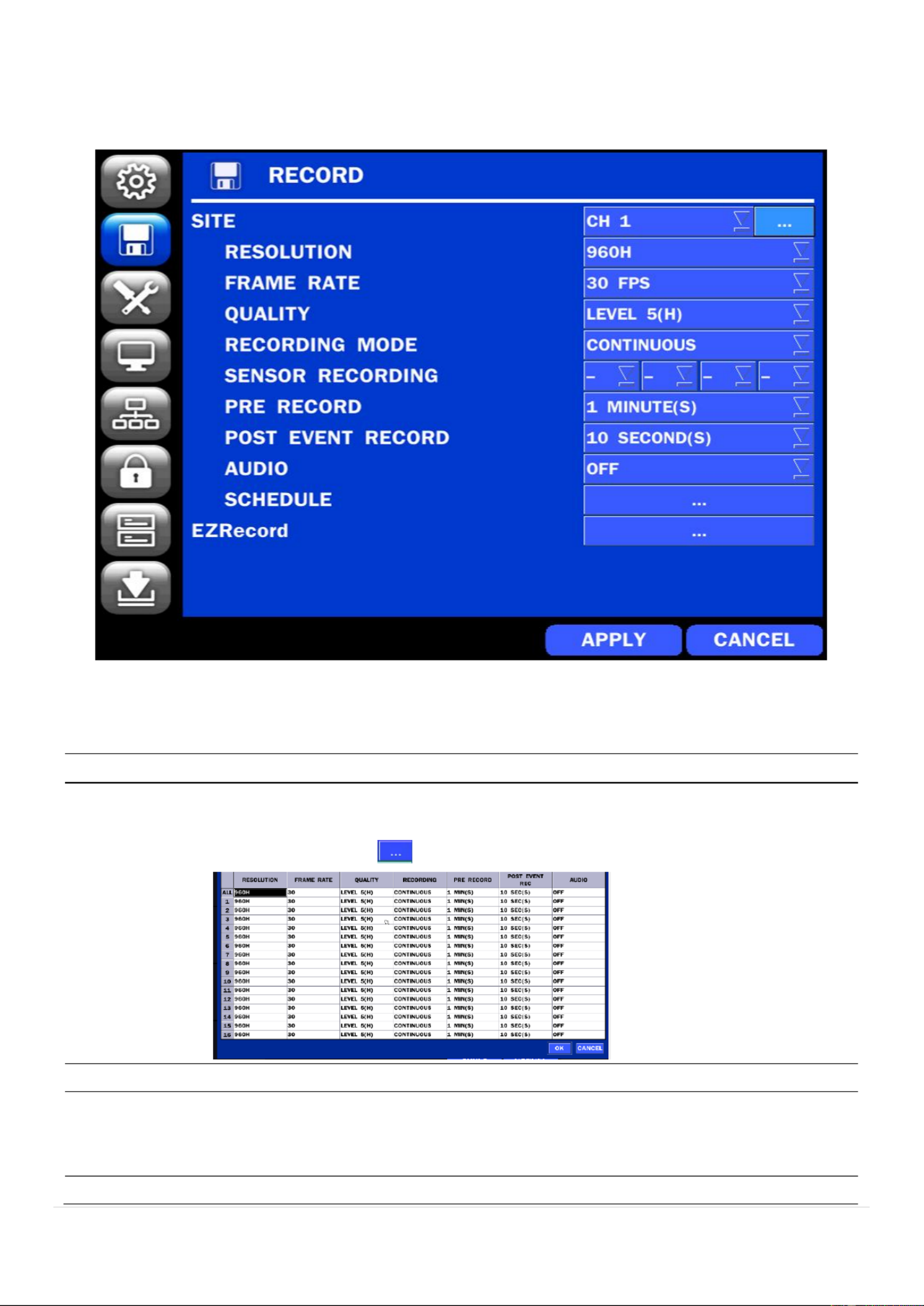
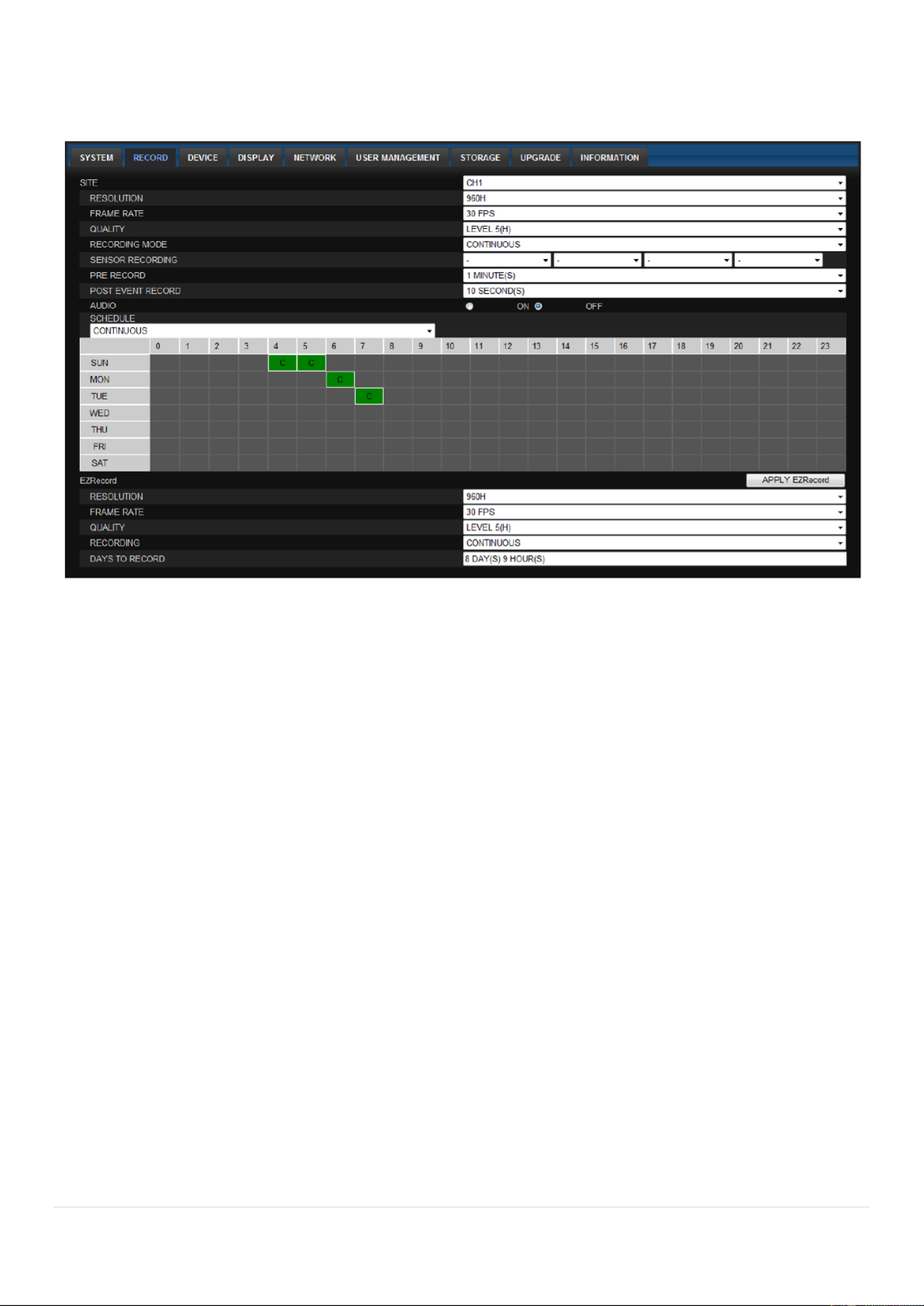
4-3. Setup RECORD Mode –
In the SETUP menu, select the RECORD tab. Then, the RECORD menu is displayed as pictured below.
Navigate through the menu items or change the settings using the mouse or the remote control.
Figure 4.3.1. RECORD Setup Screen
Table 4.3.1. Menu Items in RECORD Setup Screen
Menu Item
Description
SITE
Select channel for applying the following settings using the mouse or the remote a
control. To change the values of all channels, take the following steps:
Select the following to change the values of all channels.
RESOLUTION
Select , D1 or CIF using the mouse or the remote control.. 960H
FRAME RATE
Set the frame rate for the specied channel. The sum of the frame rate values from
each channel cannot exceed the maximum frame rates for a specic recording
resolution.
QUALITY
Select the recording quality for the selected channel. Options are:

27
Level 1 (Low), Level 2, Level 3, Level 4, and Level 5 (High)
RECORDING
MODE
Assign the recording mode for the selected channel. Options are: Continuous,
Motion, Schedule or Disable.
SENSOR
RECORDING
Select the sensor settings for the selected channel.
PRE RECORD
Enable/disable pre-event recording. Pre-event recording is limited to minutes. 20
POST EVENT
RECORD
Set the post event recording time duration for the specied channel.
(10~30 seconds)
AUDIO
Enable/disable audio recording for the specied channel.
SCHEDULE
Set the recording schedule.
EZRECORD
Set the recording EZRecord feature. by
The EZRECORD has high priority than other setting values on RECORD. a er
User can change the setting value such as resolution, frame rate, quality and
recording type. By the setting value, the DAYS TO RECORD will change
accordingly.
28
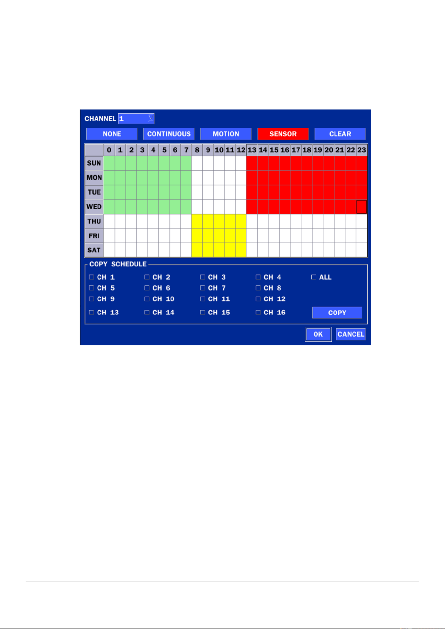
4-3-1. Recording Schedules
To setup a recording schedule, select SCHEDULE in the RECORD menu Navigate through the menu .
items or change the settings using the mouse or the remote control.
Select CHANNEL > select NONE, CONTINUOUS or MOTION > HIGHLIGHT AREA
To copy a schedule to a different channel, select the channel from the COPY SCHEDULE menu.
.
Figure 4.3 . Schedule Recording Setup Screen .2
isable recording (Displayed in White) NONE: D
CONTINUE: CONTINUOUS recording (Highlighted in Green)
: MOTION recording (Highlighted in Yellow) MOTION
: SENSOR recording (Highlighted in Red) SENSOR

29
4-4. Setup DEVICE Mode –
In the SETUP menu, select the DEVICE tab. Then, the device menu is displayed as pictured below.
Navigate through the menu items or change the settings using the mouse or the remote control.
Figure 4.4. DEVICE Setup Screen
Table 4.4 Menu Items in DEVICE Setup Screen .
Item
Description
ALARM OUT
Set the sensor, motion, and video loss for triggering alarm relay
HDD Error and Video Loss can trigger beeping.
DIGITAL DETERRENT
Setup schedule and audio recordings for Digital Deterrent.
CONTROLLER & PTZ
Set the PTZ baud rate, protocol, and ID.
SPOT-OUT
Display the channels triggered by event (Refer to 4.4.4) an
SITE
Select specied channel for motion zone setup.
MOTION ZONE
Select either Full Zone or Partial Zone for motion detection.
MOTION SENSITIVITY
Set the motion sensitivity for the selected channel.
Control the motion sensitivity from 1 to 9.
(9 Highest sensitivity, 1 Lowest sensitivity) – –
KEY TONE
Enable/disable key tone from front panel usage.
REMOTE CONTROL ID
Set the remote control ID.
1. Select ID.
2. Input the remote control ID number.
3. An icon will indicate on the Live Screen if the remote control ID is
synchronized.
The options are from 0 to 99
30
SENSOR
Select the type of each sensor.
Option is Off, Normal Open or Normal Close.
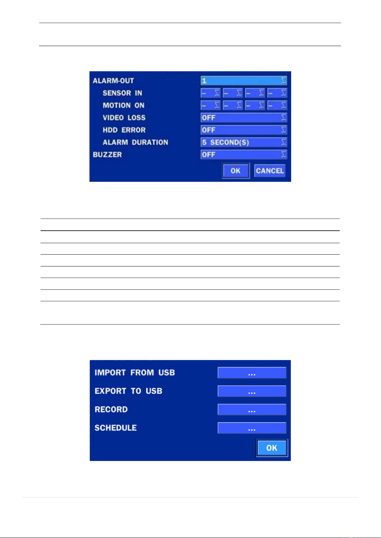
4-4-1. Alarm-Out
Figure 4.4.1. ALARM-OUT Setup Screen
Table 4.4.1. Item for ALARM-OUT Setup Screen
Item
Description
ALARM OUT
Only one Alarm-out is available.
SENSOR IN
Sensor input from 1 to 4.
MOTION ON
Camera motion detection from 1 to 4.
VIDEO LOSS ON
Camera video loss detection from 1 to 4.
HDD ERROR
HDD Failure or Error
ALARM DURATION
Set alarm dwell time from 5 to 60 seconds.
BUZZER
Set the error type for the alarm activation. The options are
OFF, ALL, HDD ERROR and VIDEO LOSS.
4-4-2. Digital Deterrent
Trigger audio message via motion detection or sensor.
Figure 4.4.2 Digital Deterrent setup scr . een
Table 4.4.2. Item for Digital Deterrent Setup Screen

31
Item
Description
IMPORT FROM USB
Import up to 8 sound les from USB.
EXPORT TO USB
Export the sound le to USB
RECORD
Select a channel and set up the date and the duration.
Select START to export audio to Digital Deterrent.
Select the play button to hear message after export .
SCHEDULE
Schedule the sound le considering the expected situation.

32
4-4-3 Keyboard Controller & PTZ Setup.
To control the PTZ functions of the camera, connect the PTZ controller to the RS-485 port on the back of
the chassis with CAT5 (or equivalent) cable.
①
①
①
①① Connect the RS-485 cables of PTZ camera to the RS-485 port on the rear panel.
Figure 4.4.3.1. Device Mode Setup Screen
Figure 4.4.3.2. Device Mode Setup Screen
②
②
②
②② Open the PTZ sub menu by selecting the submenu button.
Figure 4.4.3.3. PTZ Control Setup Screen
Note: Connect PTZ cameras that support -485 directly to the -485 port. If the camera is controlled RS RS
through an RS-232C interface, use a -232C to -485 to RS-n RS RS 232C signal converter.

33
Use the PTZ setup screen to select the following options for the camera PTZ controller:
- CHANNEL: Channel connected to a PTZ device
- CAMERA: Protocol Type
- 19200, 14400, 9600, 4800, 2400 ( rate) SPEED: Baud
- 0-ID: 63
Controller (Keyboard Controller): If a PTZ controller is used, select a controller protocol from Controller
menu. Set SPEED (Baud Rate) and ID number.
Figure 4.4.3.4 Controller Selection Screen .
4-4-4 Spot O . ut
Figure 4.4.4 SPOT-OUT Setup Screen .
Table 4.4.4. Menu Item in SPOT-OUT Setup Screen
Item
Description
SPOT ON EVENT
Enable/disable channel change if an event occurs on a channel.
SPOT EVENT
DWELL TIME
Set the dwell time for the display of the event activated channel.
(1-10sec)
SEQUENCE
Enable/disable sequential display of spot channel in full screen.
If select ON, the selected channel will be displayed on the monitor
periodically.
34
SEQUENCE
DWELL TIME
Set the dwell time for the spot channel display. -10sec) (1
SPOT CHANNEL
Select a channel for spot monitoring using the mouse or the remote
control and press OK button.
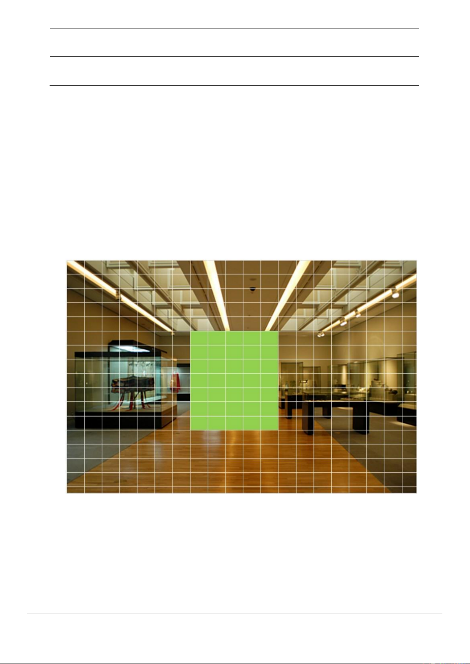
4-4-5. Motion Zone Setup
Select MOTION ZONE using the mouse or the remote control and select either PARTIAL ZONE or FULL
ZONE using the mouse control. The default value is FULL ZONE.
If FULL ZONE is selected, the motion zone grid screen is not displayed. Only set the level of sensitivity for
MOTION SENSITIVITY.
FULL ZONE: The motion sensor is active on the whole screen.
PARTIAL ZONE: The motion sensor is active in the set detection frame.
Select the motion detection position using the mouse or the remote control. Then left click on the mouse or
left click and drag the mouse pointer to select or deselect the area. Highlighted area indicates the partial
motion detection zone. Press the ESC button or right click on the mouse to return to the previous menu.
Figure 4.4.5. Motion Zone Grid Screen

38
Figure 4.6.3. NETWORK Setup Screen –DDNS
Table 4.6.2. DDNS
Item
Description
HOST NAME
This item allows the user to setup a domain name manually,
using virtual keyboard displays as shown.
SUBMIT/UPDATE
When manual host name input is done, move the cursor to this
item and select ON to submit the settings.
ezDDNS
Enable/disable ezDDNS to register the host name automatically.
4-6-3. Network Port and Web Port
Connecting DVR/DVRs through a common IP sharing device, each DVR must be assigned a unique TCP
port number for access from outside the LAN. This port number is displayed on NETWORK>NETWORK
PORT Setup MENU.
NOTE:
If you access the DVR only within the same LAN, the TCP port number does not need to
be changed.
Network access beyond a router
To access DVR beyond a router (rewall), you must open the proper TCP ports for live/playback streaming,
for commands, for remote backup, and for audio streaming. If these ports are not opened properly, you
can t access the DVR beyond a router. ‟
o For live/playback streaming, for commands, for remote backup: Open the port number
on NETWORK>NETWORK PORT menu. The default port number is 5445.
o For bi-directional audio: Open the port number NETWORK AUDIO PORT. The default on
port number is [NETWORK PORT number + 1].
o For web-viewer downloading and remote rmware upgrading: Open the port number on
NETWORK>WEB PORT menu. The default port number is 80.
4-6-4. Network Stream
User can set the RESOLUTION, FRAME RATE, and the QUALITY for the network stream.
- D16 /D16WDS: Up to 480 fps @CIF for 16 channels. DS
- D8 /D8WDS: Up to 0 fps @CIF for 8 channels. DS 24
<Note> Individual Channels can be set with dierent RESOLUTION, FRAME RATE, and QUALITY.
39
Figure 4.6.4. NETWORK Setup Screen – Network Stream
<TIP> USE MOBILE: When this function is enabled, the frame rate is limited 15fps@CIF and the video to
quality is limited to LEVEL 2 for better remote viewing on the mobile phone.
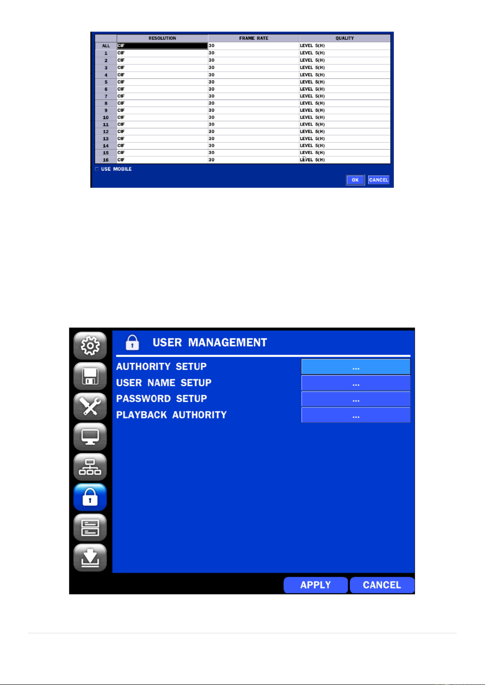
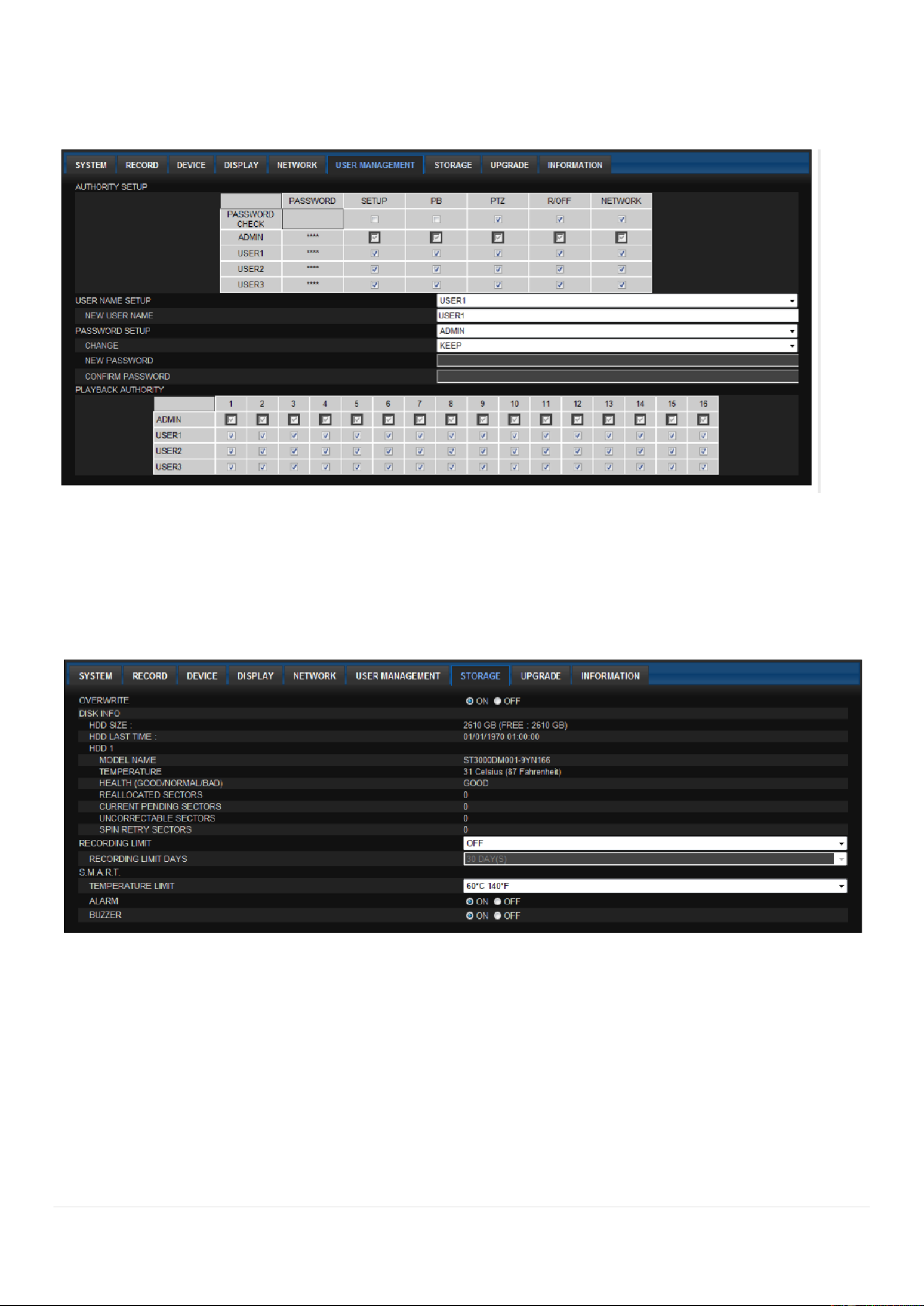
4-7. Setup USER MANAGEMENT Mode –
In the SETUP menu, select the USER MANAGEMENT tab. Then, the USER MANAGEMENT menu is
displayed as pictured below. Navigate through the menu items or change the settings using the mouse or
the remote control.
Figure 4.7 USER MANAGEMENT Setup Screen .

40
Table 4.7. Menu Items in USER MANAGEMENT Setup Screen
Item
Description
AUTHORITY
SETUP
Only the Admin will have access to the menu.
PASSWORD CHECK: Select the Checkbox to enable the functions or leave the
Checkbox blank to disable the functions.
SETUP: Enable/Disable of access to Setup
PB: Enable/Disable of access to Playback
PTZ: Enable/Disable of access to PTZ Control
R OFF: Enable/Disable of manual Record EC
NETWORK: Enable/Disable of access to Network
Selected Checkbox: The DVR will ask for a password when the given function is
selected for all users.
Blank Checkbox: The DVR will not ask for a password when the given function is
selected for all users.
ADMIN, USER1, USER2, USER3:
Selected Checkbox: The user can access the function.
Blank Checkbox: The user can not access the function.
USER NAME
SETUP
Change the name of USER1, USER2 and USER3.
Click ENTER after naming. “ ”
PASSWORD
SETUP
Options are ADMIN, USER1, USER2 and USER3.
Select USER PASSWORD using the mouse or the remote control and press SEL
button. Select user type and enter the current password. And, enter a new password,
enter the same password again to conrm and select OK. Then the message
“PASSWORD CHANGED” is displayed.
The factory default password is 1111.
It is highly recommende to assign a new password to protect the system. d
AUTHORITY
OF PLAYBACK
Set authority level of playback on each user.
Checked box: authorized to playback no authority. . Blank check box:

41
4-8. Setup STORAGE Mode –
In the SETUP menu, select the STORAGE tab. Then, the STORAGE menu is displayed as pictured below.
Navigate through the menu items or change the settings using the mouse or the remote control.
Figure 4.8. STORAGE Setup Screen
Table 4.8. Menu Items in STORAGE Setup Screen
Item
Description
OVERWRITE
When enabled, the DVR will continue recording and overwrite the oldest existing
recorded data once the hard drive is full. When disabled, recording will stop once
the hard drive is full.
DISK FORMAT
You will have an option of YES or NO for formatting the Hard Drive.
After formatting HDD, the DVR will reboot.
Caution: It is recommend to archive any data that you may need in the ed
future before formatting the hard drive.
DISK INFO
Hard drive information.
Displays the following information;

42
RECORDING
LIMIT
Enable/disable recording limit.
RECORDING
LIMIT DAYS
Set the recording limit days. - 90 days) (1
If the RECORDING LIMIT DAYS are set to 1, the data will be overwritten after 24
hours.
S.M.A.R.T
Set the alarm and beep by setting the HDD temperature limit.
Alarm will trigger alarm output.
Buzzer will trigger beeping from the internal speaker.
4-9. Setup - CONFIG Mode
In the SETUP menu, select the CONFIG tab. Then, the conguration menu is displayed as pictured below.
Navigate through the menu items or change the settings using the mouse or the remote control.
Figure 4.9.1. CONFIGURATION Setup Screen

43
Table 4.9.1. CONFIGURATION Setup
Item
Description
EXPORT TO
USB
User can save the current conguration (Setting values) of the DVR to the
USB ash drive Plug in the USB ash on the front panel and press the .
button to start the saving process.
IMPORT
FROM USB
User can upload the conguration of the DVR to another DVR using the USB
Flash drive Plug in the USB ash drive on the front panel and press the .
button to start the loading process.
LOAD
DEFAULT
Press the button to reset the system to the default settings.
The following settings such as Language DVR ID Security User , ,
Authentication, Security User P/W, Date format DLS settings, Network ,
settings, HDD overwrite, Limit recording, HDD serial number, HDD and
ERROR time will not be included.
LOAD
FACTORY
DEFAULT
Press the button to reset the system to the factory default settings.
SOFTWARE
UPGRADE
Upgrade softeware to the latest version.
After connecting ash ive to USB port on the DVR, click SEARCH. USB dr
It will automatically nd the upgrade le.
4-9-1 Firmware Upgrade .
1. Create a new folder named “upgrade” in the USB flash drive root directory.
2. Create sub-folder for each model under “upgrade” folder and copy each firmware.
For D16DS/D16WDS Models:
- Folder name d ds– “ 16 ”
- File name main_D16DS_speco_*.*.*– “ _201****”.bin
For D8 /D8WDS Models: DS
- Folder name d8ds– “ ”
- File name main_D8DS_speco_*.*.*– “ _201****”.bin
3. Plug in the USB ash drive on the rear panel.
4. Navigate to CONFIG menu of SETUP.
5. Select SOFTWARE UPGRADE.
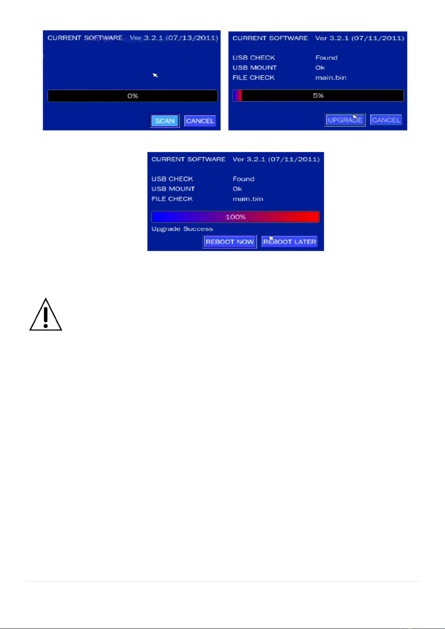
6. Follow the procedure from Figure 4.9.2 to Figure 4.9.4 .
44
Figure 4.9.2 Figure 4.9.3
Figure 4.9.4
NOTICE
1. If selecting REBOOT LATER, the upgraded software will not be applied til the system un
reboots.
2. If selecting REBOOT NOW when the USB ash drive is plugged, the following message
will pop up. Remove the USB ash drive and select OK.
5. Live, Search and Playback
5-1. Live View
In the Live screen, video inputs from the cameras are displayed as they are congured in the Display Setup
screen. Various On-Screen Display (OSD) symbols, which indicate the status of the DVR, are described in
Table 5.1.1.

45
Figure 5.1.1. Live Screen Quick Operation Window and
Table 5.1.1. Status Indicator Icons in Live Viewing Screen
Icon
Description
Indicates the DVR is locked. Note) to unlock, right click on the live view
screen and click on Unlock.
Audio mute.
To select audio output, press the Audio after click the right button on the
mouse.
Toggle from Audio 1 to 4, mute in order.
Indicates that alarm is set. To set the alarm function, press the Alarm button
on the front panel.
Indicates that alarm output is activated.
Event indicator. When there is an event (motion recording, video loss, HDD
fail, S.M.A.R.T), this icon will be highlighted.
Indicates that a network client is connected to the DVR.
Indicates that sequencing mode is enabled.
Displays the current date and time.
RC: ALL
Remote control ID display. If a remote ID is not set, the message “ALL” is
displayed.

46
Displays the amount of recording on the hard disk from 0-99%.
Indicates that HDD is recycled.
Continuous recording in progress.
Manual recording in progress. To set the Manual recording mode, press the
Record button on the front panel.
Motion alarm recording in progress.
Sensor recording in progress.
Right click the mouse, and the quick operation window will be displayed as below.
Figure 5.1.2 Quick Operation Window .
Table 5.1.2 Menu Items in Quick Operation Window .
Icon
Description
EZ SETUP
Select this option to enter the EZ Setup menu.
SETUP
Select this option to enter the Setup menu.
AUDIO
Select this option to set an audio channel to output ;

48
SYSTEM
LOCK
Lock/Unlock Setup button.
SYSTEM
SHUTDOWN
Click this button to shutdown system.

49
5-1-1 PTZ Control.
Table 5.1.3. Menu Items in PTZ Control Window
Item
Description
INITIALIZE
Initialize the PTZ settings of the selected camera
PAN/TILT
Select PAN/TILT using the button▲▼◀ and ▶,
then
press . Adjust the tilt (UP/DOWN)/pan SEL
(LEFT/RIGHT) position using the ▲▼◀and ▶
buttons.
ZOOM/FOCUS
Select ZOM/FOCUS using the and ▲▼◀ ▶
buttons, then press . Adjust the zoom SEL
(UP/DOWN)/ focus (LEFT/
RIGHT)position using the buttons. ▲▼◀ and ▶
OSD
Select OSD to enter the menu. Control keys are
Right, Left, UP, Down, Select, Far (REW KEY), and
Near (FF KEY). Press the button to return to ESC
the previous menu. Press the button to close PTZ
the OSD menu.
AUTOSCAN
Press the right ke ) to start auto scan. Press the y(▶
left key ( ) to stop auto scan. ◀
PRESET
Select PRESET, then press the left key( ). A ◀
number input window will appear. Set the number
(3digits) using the number key, then press the SEL
to conrm the preset number for the current position.
Press the right key ( ) and enter the number ▶
(3digits) to go to the preset position.
TOUR
Select TOU and press the right ( key. A number ▶)
input window will open. Select a number (1digit)
using a number key, then press SEL to start the tour.
Press the left ( ) key to stop the tour. ◀
Preset the number of the tour group in the OSD
menu.
NUMBER
For the TOUR and PRESET menu.
Press ESC to return to the main menu
5-2 Digital Zoom in Live and Playback Screen .
D series supports Digital Zoom feature during live and playback mode. S
1. Double click the target channel.

50
2. Click the left button of the mouse and drag to make rectangular shape.
5-3. SEARCH Screen
To enter the search screen menu, select SEARCH menu on the screen using the mouse or press SEARCH
icon on live screen.
Figure 5.3. Search Screen
There are 7 ways of search menu such as EZSEARCH, TIME LINE (Calendar), EVENT, GO TO FIRST
TIME GO TO LAST TIME, , GO TO SPECIFIC TIME, ARCHIVE LIST, and LOG LIST on the screen.
51
5-3-1. EZSearch
The EZSearch window is used to find stored video with ease using the thumb nail playback screen .
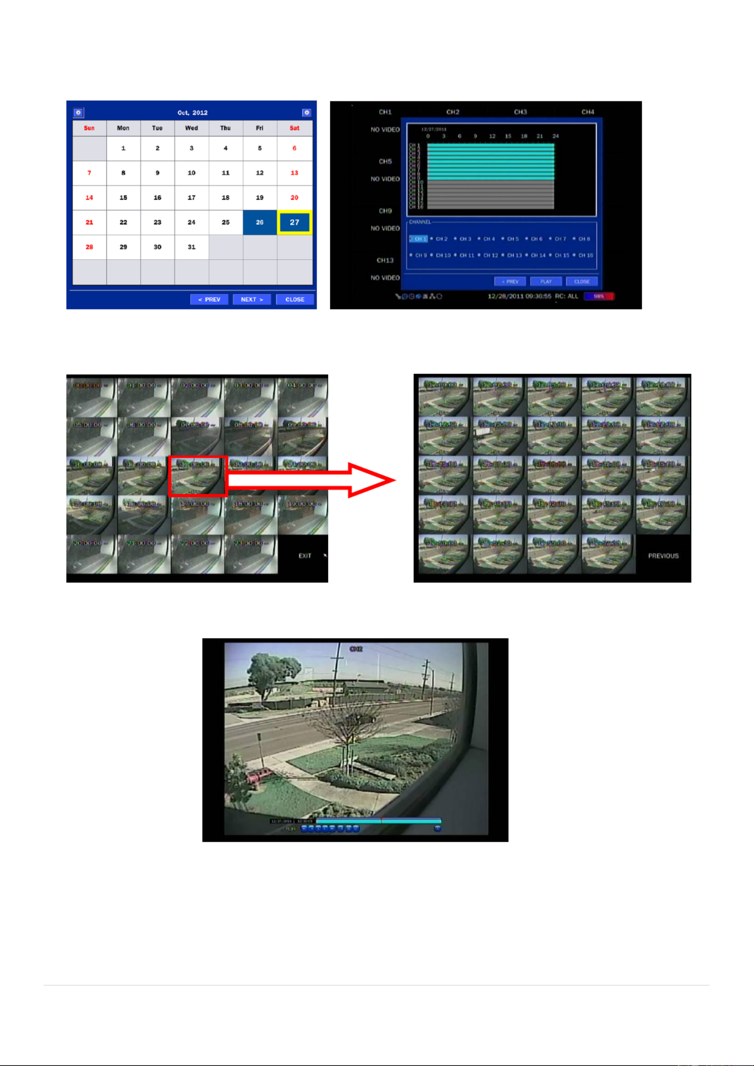
Figure 5.3.1.1. Calendar Screen Figure 5.3.1.2 Channel Selection Screen .
Figure 5.3.1.3. 24 Hourly Thumbnail Screen Figure 5.3.1.4 Minut Thumbnail Screen . e
Figure 5.3.1.5. Play Mode Screen
1. When the EZSearch menu is selected, the user can see a calendar, which displays recorded dates with
highlights. Select a specific date on a calendar.
2. Select a channel from Channel Selection Screen. Then, 24 Hourly Thumbnail Search screen displays.
3. Select the hourly thumbnail. Then, Minute Thumbnail Search screen displays.
4. Select the thumbnail of minutes that you want to playback.

53
Figure 3.3.2. Event Search Screen 5.
5-3-4. Go To First Time
You can access from the oldest recorded data on the DVR hard drive by selecting GO TO FIRST TIME
on the SEARCH window. Press the PREV to return to the SEARCH window.
5-3-5 Go To Last Time .
You can access from the last minute recorded data on the DVR hard drive by selecting GO TO LAST
TME on the SEARCH window. Press the PREV to return to the SEARCH window.
5-3-6 Go To Specific Time .
User can search for video data from a specific instance by setting the date and time in the GO TO
SPECIFIC TIME menu. Use the mouse or the remote control to change the date and time value and
press the PLAY button after setting. If there no video data in the set date and time, No Data Exist is
message displays.
5-3-7. Archive List
The ARCHIVE Search window is used to find previously stored video or images.
Figure 5.3.7. Archive Search Screen
When the Archive menu is selected the user can see a calendar, which has recording data. Select a ,
specific date and then the archived data will be displayed Press the Display button to view the still image or .
the first frame of the selected video, then the user can save the selected data.

54
5-3-8. Log List
You can access the LOG list search screen by selecting LOG on the SEARCH window.
Figure 5.3.8 List Screen . Log
When the Log menu is selected, the user can see a calendar, which has a log data. Select a specific date
and press NEXT button, and then the log data will be displayed. Press the SAVE button to save the data
and then the data is saved as a text file format.
5-4. Play Mode
During playback of a recorded event, the mode changes from SEARCH to PLAY. While in PLAY mode, you
may return to the SEARCH screen by pressing the X button on the status bar.
Figure 5.4.1. Play Mode Screen
The following status bar hides automatically and appears again if a mouse pointer is positioned to the
bottom of the screen.
Table 5.4.1. Button Functions in PLAY Mode
Button
Description
, 4x, 8x,16x, 32x speeds at 4 split screen 2x
, 4x, 8x,16x at 9 split screen 2x
2x, 4x, 8x at 16 split screen
Single Channel backward playback speed 1x, 2x, 4x, 8x, 16x, 32x, 64x

55
Jump/Step backward. The playback position moves 60 seconds backward.
Press to play or pause recorded video.
Jump/Step forward. Playback position moves 60 seconds forward.
, 4x, 8x 6x, 32x speeds at 4 split screen 2x ,1
, 4x, 8x,16x at 9 split screen 2x
, 4x, 8x at 16 split screen 2x
Single Channel forward playback speed 1x, 2x, 4x, 8x, 16x, 32x, 64x
Slow Mode play. Forward playback speed x1/4, x1/2
Press to backup the video.
EZCopy button.
Return to the previous menu screen, search window, or exit from the Menu.
6. Back Up
6-1. Still Image Backup onto USB Flash Drive
Still images can be captured and archived onto a flash drive or a external hard drive in live USB n USB
mode or while playing back recorded video.
1. Select a specific channel, which wants to backup on live screen.
2. When you press SNAPSHOT button on Quick operation window, the media selection window screen
will display.
3. Once you press START button, the system will capture a still image and archive onto a USB flash drive.
NOTICE
USB Flash Drive must be in FAT32 file format.

56
6-2. Video Backup onto USB Flash Drive during playback
Video can be captured and archived onto the US ash drive or hard drive while playing back the B a
recorded video. In playback mode, press the BACKUP button to launch the backup function.
1. When you press BACKUP button on the selected channel or all channels, the DVR will ask
whether to archive a Still Image NSF or AVI and select the proper media type. , a
2. Select USB STICK (Flash Drive) to back up less than an hour.
Select USB HDD (Large Backup) to back up from 1 hour to 24 hours.
3. Once you select the channel and duration, the system will start to archive the data to the USB drive.
4. The following image shows the progress of archiving the data.
5. The following shows the image to complete the backup. Select lose to return to the previous screen.

57
6-3 EZCopy: Video Backup onto USB Flash Drive during playback .
Using EZCopy feature, Video can be easily archived onto the USB ash drive or a hard drive.
In playback mode, press the button to launch the backup function. EZCOPY
1. Press EZCOPY button on the selected channel or all channels.
2. Then, EZCOPY START time will display.
3. Move time bar cursor to the time of end of backup and press EZCOPY button Then, EZCOPY .
STOP time will display.
4. EZCOPY window will display. The DVR will ask whether to archive a Still Image NSF or AVI. , a

59
Figure 6.3.1. Archive Search Screen
6-5. Playback of Backup Video
6-5-1 AVI Format .
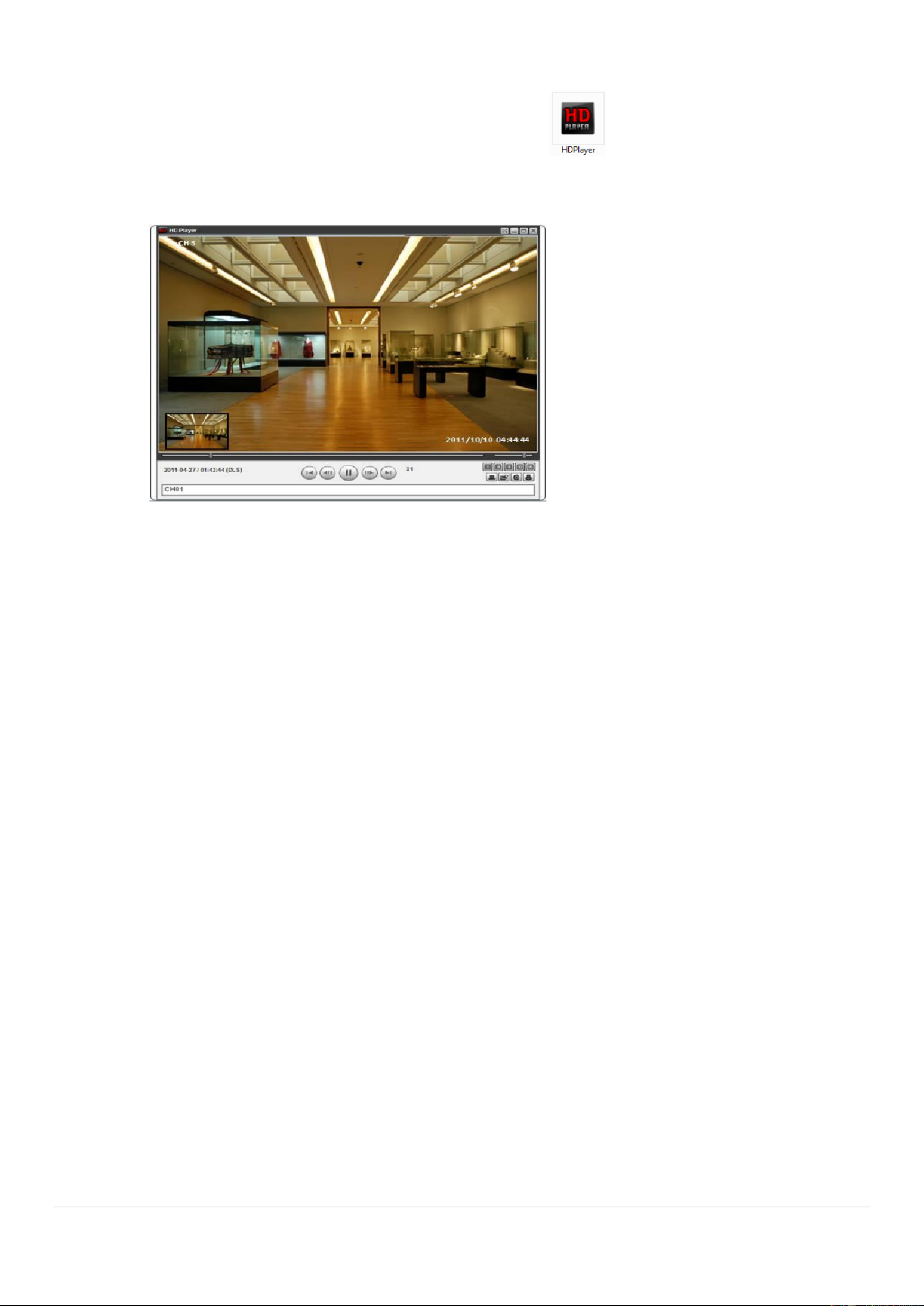
AVI format: AVI format video can be played back by Window Media Player or other media player that is ™
compatible with AVI format video.
1. Please install the UMSDecoderFilter that the DVR copies DvrPlayer folder on USB flash dri “ ” ve
with the video. UMSDecoderFilter is exported to the “/DvrPlayer” folder of the USB drive.
2. Otherwise, the video and time stamp over video can t be properly playbacked and displayed on ‟
Window Media Player .™
Timestamp On AVI. The subtitle is embedded to the video clip le.
The subtitle is embedded to the AVI le. To display a subtitle, user should install a special lter
called “UMSDecoderFilter”.
60
6-5-2 NSF Format .
NSF format: NSF format video can be played back using player that the DVR copies to the HD
“DvrPlayer folder on USB ash drive with video. Use the mouse scroll to use digital zoom in and out ”
feature.

61
7. Network Access Using the Multi-Sites Network Viewer
7-1. Overview
The SpecoTech Multi Client is a multiple site monitoring client software with; video, audio, and alarm signals
from the DVRs over networks. The SpecoTech Multi Client does not limit the number of DVR units to
register.
The program displays 16 DVRs and supports dual monitors. up to
On the program, user may control PTZ cameras on the DVRs. By attaching a microphone and speaker
system to devices on site, the user may make bi-directional audio communication over the network.
7-2. PC Requirements
Minimum Requirements PC
Recommended Requirements PC
Before installing the program, check the PC specications. The DVR remote software may not perform
correctly if the PC does not meet the minimum requirements.
CPU
Intel re i3 Co
1.8Ghz
Memory
2GB DDR2
VGA
512MB
Resoluon
1280x720
Disk Space
1GB
OS
Windows 2000, XP Professional, XP Home, Vista, 7 (NOTE: Not all versions of Vista and 7
are supported)
Network
10/100Base T
Others
Direct X 9. or Higher 0c
CPU
Intel Core i5
2Ghz or higher.
Memory
4GB DDR3 or higher.
VGA
512MB or higher.
Resoluon
1920x1080
Disk Space
1 GB
OS
Windows 2000, XP Professional, XP Home, Vista, 7 (NOTE: Not all versions of Vista and 7
are supported)
Network
10/100/1000Base T
Others
Direct X 10 or higher.

62
7-3. Installation of the Program
1. Insert the provided CD in the CD drive and double- SpecoTech Multi Client (XXXX)click “ .exe”
2. Select a destination folder and click “Next”.
3. Select the program folder and click “Next”.
4. The installation status screen is displayed.
5. After the installation is completed, “SpecoTech Multi Client” icon displays on the desktop screen.

64
SETUP
Click this icon to setup conguration of UMS MULTI CLIENT.
CAPTURE
Click this icon to capture a still image.
EVENT LIST
Opens list of events logged by the UMS Multi Client.
PAUSE
Click this icon to play/pause live video.
ALARM ON
Click this icon to turn on/off alarm outputs.
RECORD ON
Enable or disable recording of live video to local disk, which has set in
setup menu.
AUDIO
Use the volume control bar to set the audio level.
MIC
Use the microphone volume control bar to set the micro phone level.
PRESET/TOUR/SCAN/MENU
User can control PRESET/TOUR/SCAN/MENU
CHANNEL SPLIT
To select the numbers of display channel/channels (Single, quad, 9
channels, and 16 channels) of highlighted site.
DVR SITE SPLIT
To select the numbers of DVR/DVRs (1 DVR, 4 DVRs, 9 DVRs, 16
DVRs) on main display screen.
7-5. Search and Playback Window
7-5-1. Main User Interface
You can access to search window by clicking the search icon (Local Playback / Remote Playback) on the
upper right of the Live Window.

65
7-5-2. Main Control Panel
Button
Description
LOCAL PLAYBACK
Click this icon to run a playback window to search and play videos that
are recorded in the local PC.
REMOTE PLAYBACK
Click this icon to run a playback window to search and play videos that
are recorded in the remote DVR.
THUMBNAIL REFRESH: Click this icon to refresh and renew
thumbnail image of the connected sites .
SITE ADDITION: Click this icon to open „Site Addition‟ window.
SITE DELETE: Click this icon to delete site from the index
window, after disconnect a site.
NET FINDER: Select the site from the index window and click this
icon to modify the information of specic site.
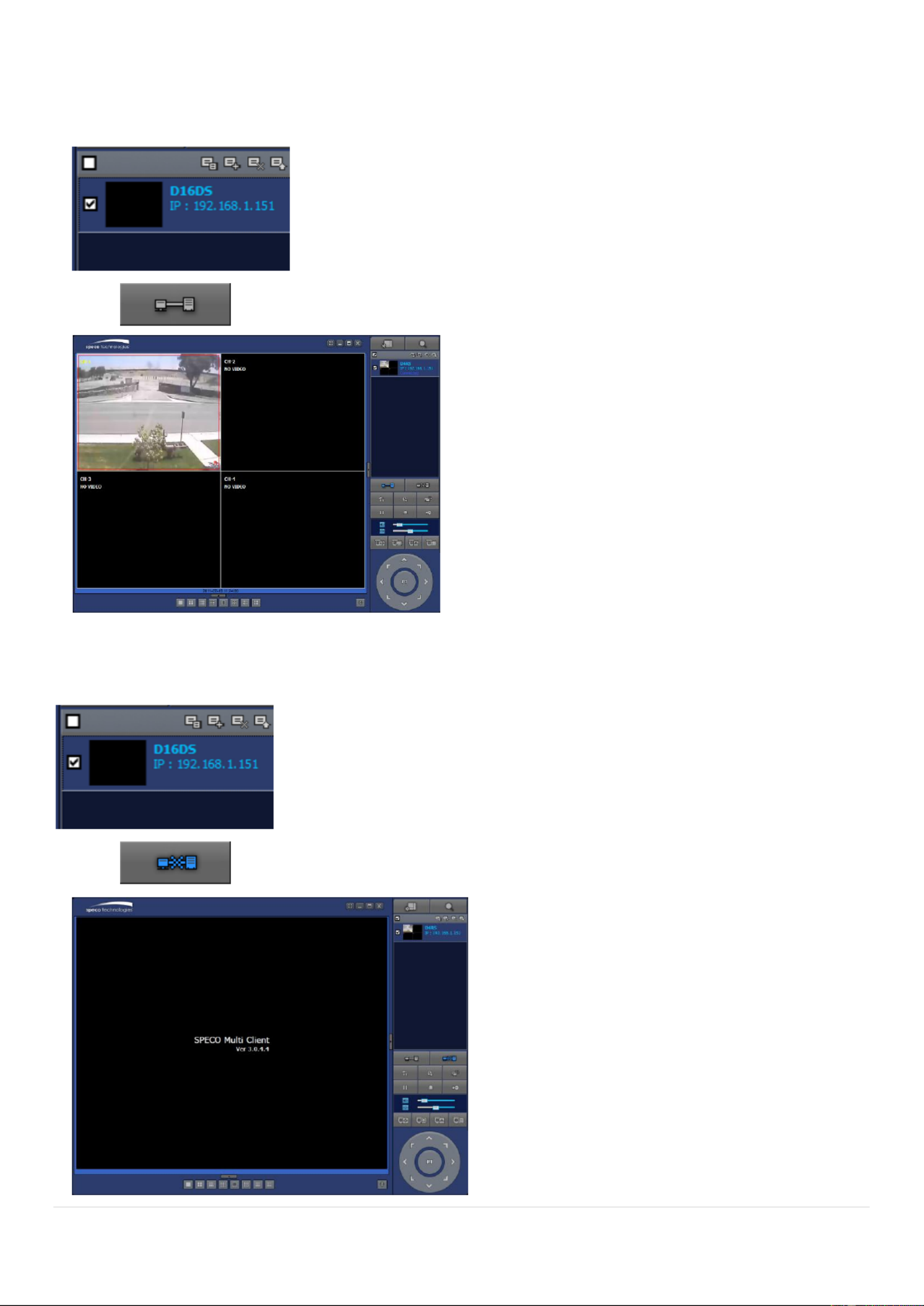
CONNE CT
Click this icon to connect the selected site/sites.
DISCONNECT
Click this icon to disconnect the selected site/sites.
SETUP
Click this icon to setup conguration of SpecoTech Multi Client.
CAPTURE
Click this icon to capture a still image.
EVENT LIST
Opens list of events logged by the UMS Multi Client.
EZCopy Start
Click this icon to set the beginning time for backup of the recorded
video in AVI format.
EZCopy End
Click this icon to set the ending time for backup of the recorded video
in AVI format.
BACKUP
Click this icon to backup the recorded video in AVI format.
AUDIO
Use the volume control bar to set the audio level.
To select the numbers of DVR/DVRs (1 DVR, 4 DVRs, 9 DVRs, 16
DVRs) on main display screen.
To select the numbers of display channel/channels (Single, quad, 9
channels, and 16 channels) of highlighted site.

66
To select the channel to playback.
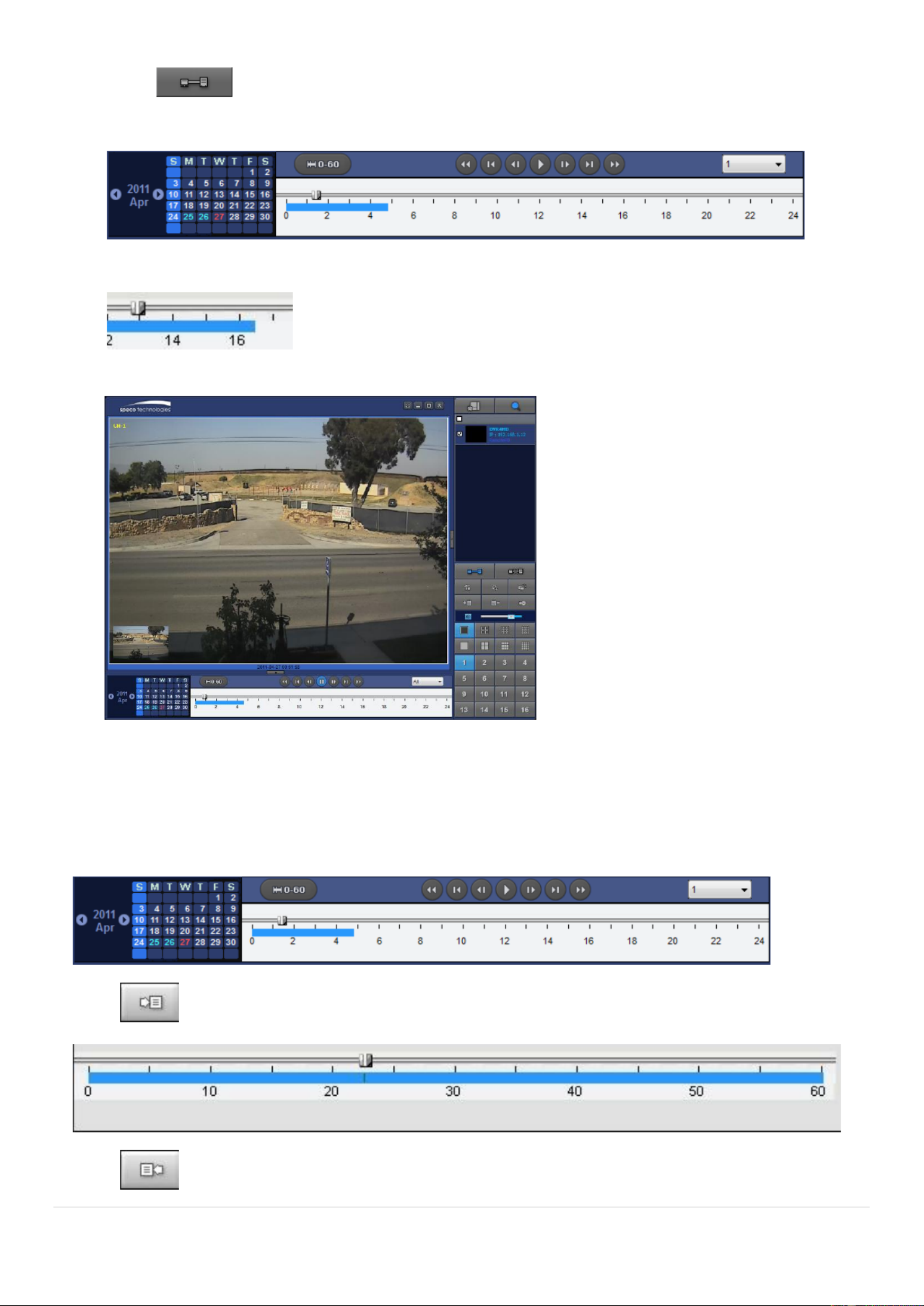
The calendar shows dates with recorded video in color.
To display the recorded data of selected channel or all channels on a
time line scale.
To change a timeline scale from 24 hours to 60 minutes.
The timeline shows recorded data in color on the bar. You can adjust
the timeline scale and move it to the time you wish to playback. Then
click the play icon to display the recorded video.
Playback buttons.
Thumbnail search over the network.
- List the thumbnail 24images from 00:00 to 23:00.
- Select one of 24 images every 150sec for an hour.
- Then play the tile
* Click the PREVIOUS button to go the previous step. “ ”
Digital Zoom Window in Live and Playback. (Only available in Single
Channel Viewing)
7-6. Setup of SpecoTech Multi Client
Click the setup icon to setup the conguration of UMS Multi Client software. The SETUP
window is displayed as below.
7-6-1. General
Security Option: Set a password for security options. Select security options and set a password.
Then when you access any of selected functions, you need to enter the password.
You can also set the save path for capturing and backup.
Save Path: Specify the location to save captured still image for Capture and Backup data.
Miscellaneous
Automatic Reconnection: If enabled, the software will automatically try to reconnect to the last
successful IP address. But, when CLIENT ESS is OFF on the DVR, the software will not try to ACC
reconnect even if it is enabled.
Always On Top: If enabled, the software display will be continuously on the top of other windows.
Time Format: Change the way the Client software displays the time.

69
Record Local Stor Setup: age You can select the local disk to record and the amount of disk space you
want to allow the program to use for recording. You can also select the option to overwrite data or stop
recording when the maximum amount of disk space is full.
7-6-4. Display
You can select the OSD (On Screen Display) to be display ed.

70
7-6-5. Language
English, French and Spanish is selectable.
7-6-6. About
“About” provides network client version information.
71
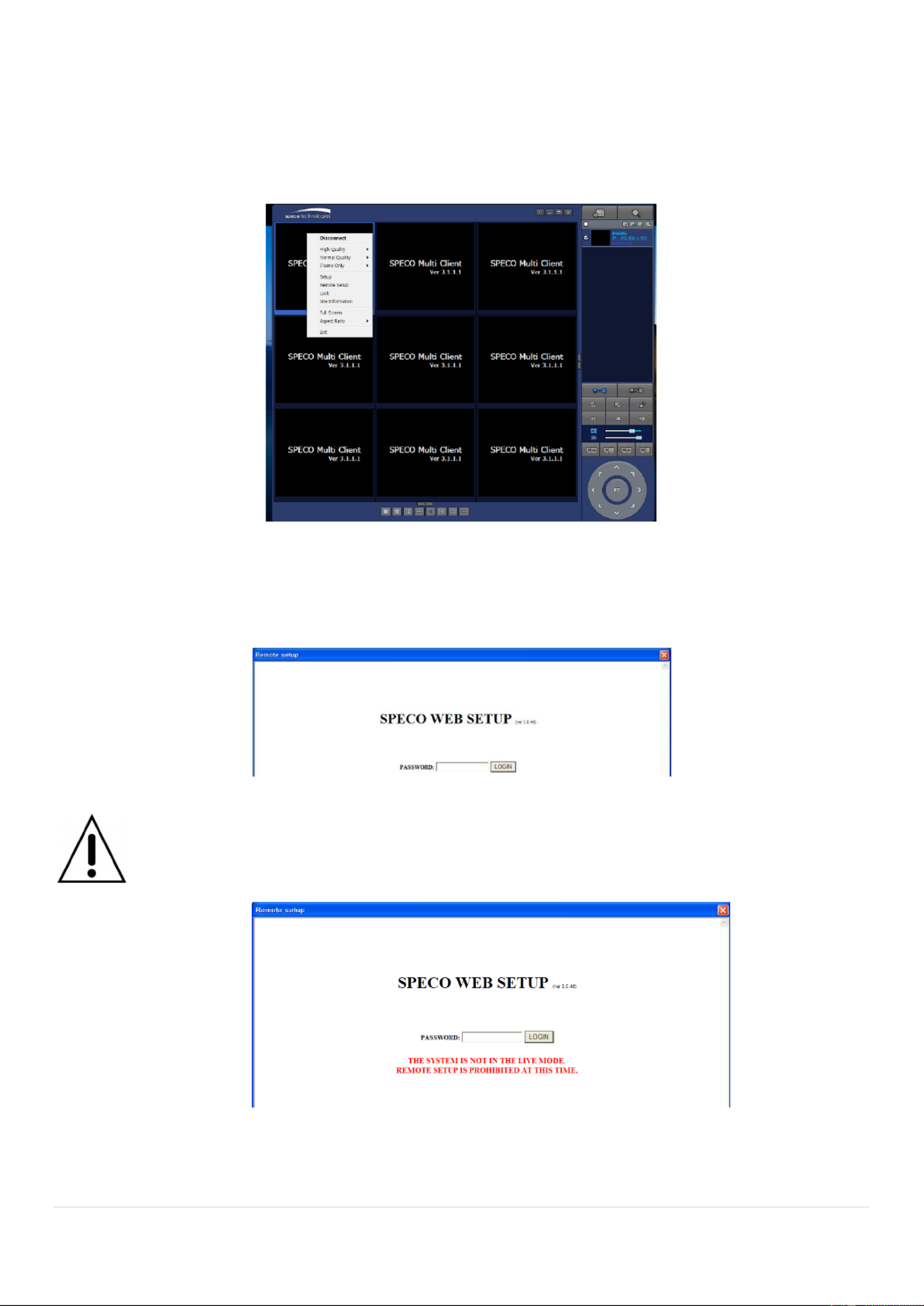
7-7. Remote Setup
The menu settings for the DVR unit can be set over network.
Put the cursor of the mouse on the channel, which is connected to the site and right click on the mouse to
open the submenu. Then the following window is displayed as below. Select the REMOTE SETUP.
Then the setup window is displayed. The specied menu screen is displayed on the upper left of the screen.
Enter the password of the DVR when prompted. (NOTE: The default password is 1111)
Setting is the same as with the DVR menu setting. Refer to the corresponding pages for details on the
setting items.
NOTICE
Web Setup is prohibited when DVR is in local Setup Menu.

72
7-7-1. System
Select System to set system and time settings.
DATE DISPLAY FORMAT: Select the date display format.
CLIENT ACCCESS: Enable/Disable remote access through network client software.
NTP SETUP: Sets whether to synchronize the time using NTP server or not.
o Primary SNTP Server: Input the NTP primary server address.
o Secondary SNTP Server: Input the NTP secondary server address.
o Time Zone: Select the time zone.
o Connection Mode: Select the connection mode to NTP time server.
: Sets whether to enable/disable e-mail sending function. S E-Mail SETUPEND
o TRANSMISSION MODE: Select the mail transmission mode (TEXT or VIDEO).
o IP NOTIFICATION: Enable/disable sending e-mail when the IP address is changed.
o MAIL BY SENSOR: Enable/disable sending e-mail reports when an alarm event is triggered.
o MAIL BY MOTION: Enable/disable sending e-mail when the motion is detected.
o MAIL BY VIDEO LOSS: Enable/disable sending e-mail when the video loss is detected.
o MAIL BY S.M.A.R.T.: Enable/disable sending e-mail reports when S.M.A.R.T. is triggered
o MAIL DVR STATUS: Enable/disable sending periodical e-mail of the system status.
o MAIL PORT: Mail port setting.
o SEURE OPTION: Select a secure mail server connection. (SSL or TLS )
o MAIL TO: Input the appropriate email address to enable sending e-mail reports
o MAIL SERVER: Input the SMTP server name as well as the user ID and password.
o MAIL FROM (Return Mail Address): Set the source e-mail address to be notied to the
destination.
USER NAME: Name the DVR
73
7-7-2. Record
Select RECORD tab to set the recording conditions.
These settings apply to the specied channel only.
Recording Setup
o RESOLUTION: Sets the resolution for the recordings. The set value applies to an individual
channel.
o FRAME RATE: Sets the recording rate.
o QUALITY: Sets the image quality in 5 levels.
o RECORDING: Sets the recording mode.
o RECORDING MODE: CONTINUOS, SCHEDULE, MOTION
o PRE RECORD: Sets whether to perform or not pre recording.
o POSE EVENT RECORD: Sets the duration of the event recording.
o AUDIO: Sets whether to perform or not audio recording.
o SECHDULE: Sets the schedule recording.
These settings apply to all channels.
EZRECORD
o RESOLUTION: Sets the resolution for the recordings. The set value applies to an individual
channel.
o FRAME RATE: Sets the recording rate.
o QUALITY: Sets the image quality in 5 levels.
o RECORDING MODE: Sets the recording mode.
o RECORD DAYS: By the setting value, the Recording Days will change accordingly.

74
7-7-3. Device
Select to set Spot Out, Enable/Disable CVBS Out, motion zone. Device
ALARM OUT: Set the sensor, motion, and video loss for triggering alarm relay HDD Error and
Video Loss can trigger beeping.
GITAL DETERRENT:DI Set the schedule of digital deterrent function and upload the sound le to
DVR.
CONTROLLER: Set the controller baud rate ID. and
PTZ: Set the PTZ baud rate, protocol, and ID.
MOTION: Setup the motion detection area and the sensitivity.
o SITE: Select the channel
o MOTION ZONE: FULL Zone or PARTIAL Zone
o MOTION SENSITIVITY: 1~9 (High sensitivity level)
KEYTONE: Sets On or Off of Key Tone.
REMOTE CONTROLLER ID: Sets an ID number on the supplied remote control for its identication.
Select the type of each sensor. SENSOR:

75
7-7-4. Display
Select the DISPLAY tab to set the DISPLAY conditions.
These settings apply to all channels.
OSD: Sets whether to display or not date and time as well as channel number on the screen.
OSD CONTRAST: Adjust the character contrast on the screen.
MAIN MONITOR SEQUENCE: Setting for automatically switching the displayed video.
SEQUENCE DWELL TIME: Sets the interval for automatically switching the screens.
SITE: Name, Covert, Brightness, Contrast, Hue, Saturation
These settings apply to the specied channel only.

76
7-7-5. Network
NETWORK TYPE ( Cannot be altered remotely )
o STATIC: The address setting mode is manual. Input IP, Gateway, Subnet Mask, and DNS IP.
o : The address setting mode is automatic. DHCP
: Set whether to use DDNS service or not DDNS
o HOST NAME: Allows the user to setup a domain name manually
o SUMBIT/UPDATE: Select ON to submit the settings
o ezDDNS: Enable ezDDNS to register the host name automatically
NETWORK PORT: When connecting multiple DVRs to the network, set a unique port number.
NETWORK AUDIO PORT: Display the network audio port (NETWORK PORT + 1).
: Set a web server port number. WEB PORT
NETWORK STREAM: Set the Resolution, Frame Rate, and the Quality.
WIRELESS LAN: Set the IP Address, SSID and KEY (PASSWORD).
77
7-7-6 User Management .
Select the USER MANAGEMENT tab to set the DISPLAY conditions.
7-7-7. Storage
Select Storage to congure continued recording settings by overwriting the hard disk and the storage
period for the recording data.
OVERWRITE: Select on to continue recording by overwriting when the hard disk becomes full.
RECORD LIMIT: Sets whether to limit or not the recording data storage period.
S.M.A.R.T.: Sets the TEMPERATURE LIMIT of the Hard Disk to trigger the ALARM and the
BUZZER.

78
7-7-8. Remote Upgrade
Shows the current Firmware version installed on DVR.
Select BROWSE to locate the rmware le. Browse:
Select UPGRADE to upgrade the rmware of the DVR. Upgrade:

79
7-8. Operation
7-8-1. Addition, Delete, and Modify of DVR Sites
7-8-1-1. Addition of Sites
1. Click SITE ADDITION button. And then the following window will be displayed as below.
o Input a name that properly describes a site. Site Name:
o IP Address: Input IP address (Public IP address of a router that DVR is connected.) or Domain
name
o Port Number: Default Port Number is “5445”.
o Input ID of DVR. ID: Default ID is “admin”.
o Input network password of DVR. Password: Default Password is “1111”.
2. Click OK button. And then the registered site is added on the directory window.
7-8-1-2. Deleting a Site
1. Select the site/sites to delete from the directory window.
2. Click SITE DELETE button. And then the selected site/sites is/are deleted.

80
7-8-1-3. Modify of Sites
1. Select the site/sites to modify from the directory window.
2. Click NET FINDER button. And then the following window will be displayed as below.
3. Click MODIFY button. And then the modied information is displayed as below.
81
7-8-2. Connect and Disconnect
7-8-2-1. Connect
1. Select site/sites to connect from the directory window.
2. Click CONNECT button, and then site/sites displays/display as connected.
7-8-2-2. Disconnect
1. Select site/sites to disconnect from the directory window.
2. Click DISCONNECT button, and then selected site/sites disconnected.

83
4. Click RECORD ON button. And the color of button is changed.
5. Live video data is recorded as set in Record and Disk setup. These video data can be searched and
play-backed with Local Playback.
7-8-5. Local Playback and Remote Playback
7-8-5-1. Playback of Recorded Video on a Local PC
1. Click LOCAL PLAYBACK. And then Playback Window l be displayed over the Live wil
Window.

84
2. Select site/sites to connect from the directory window.
3. Click CONNECT button. And then Green bar displays on Search calendar
and timeline scale window.
6. Move the marker on the timeline scale to where there is video data and press the PLAY button.
7. Video data that is recorded on local PC will be play-backed.
8. Use the mouse scroll to digitally zoom in and out from a single channel display.
7-8-5-2. Playback of Recorded Video o Remote DVR n
1. Click REMOTE PLAYBACK. And then Playback Window will be display over the Live ed
Window.
2. Select the site to connect from the directory window.
85
3. Click CONNECT. And then Green bar displays on Search calendar and timeline scale
window.
4. Move the marker on the timeline scale to where there is video data and press the PLAY button.
5. Video data that is recorded on the remote DVR is play-backed.
7-8-6. AVI Backup during Playback
You can back up the recorded videos in AVI format during playback.
1. Double-click the target channel to backup.
2. Select the beginning time by using the search calendar and timeline scale bar.
3. Click EZCOPY START button on the timeline scale select the beginning point of the backup. to
4. Click EZCOPY END button on the timeline scale to select the ending point of the backup. Then,

86
the selected starting point and the ending point on the timeline scale bar will be marked in green.
5. Click BACKUP. And then the BACKUP window will be displayed as below.
6. You can also set the beginning time and ending time on this window. After selecting a channel for backup,
click the OK button. The backup will begin.

88
5. The Web Browser Viewer will be displayed as below after the ActiveX installation
6. Click the CONNECT button on the Left upper corner of web-viewer. Then “Connect” dialog is
displayed.
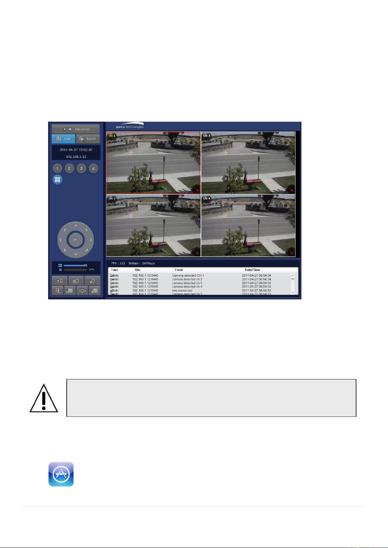
89
Input a name that properly describes a site. Site Name:
IP Address: Input IP address (Public IP address of a router that DVR is connected.) or Domain
name
Port Number: Default Port Number is “5445”.
Input ID of DVR. ID: Default ID is “admin”.
Input network password of DVR. Password: Default Password is “1111”.
7. Then the cameras connected to the DVR are displayed on the screen.
8. Use mouse scroll to digitally zoom in and out from a single channel display.
9. Network Access Using the Smart Phone Viewer
9- App Viewer for iPhone 1.
1. Enter the Apple App Store.
2. Search Speco Player in the App Store. “ ”
Notice
Data Usage applied without Wi-Fi connection. Please check with your Phone Carrier.

90
9-1-1. Live
1. Open the installed “Speco Player click button to add a remote device. ” App and
2. Enter the site name, IP or DDNS address, Network Port number (default 5445), ID(default admin) and
Password (default 1111). Then, click Save“ ” buon.
* Note: Network Port and Web Port must be forwarded before adding a new site.
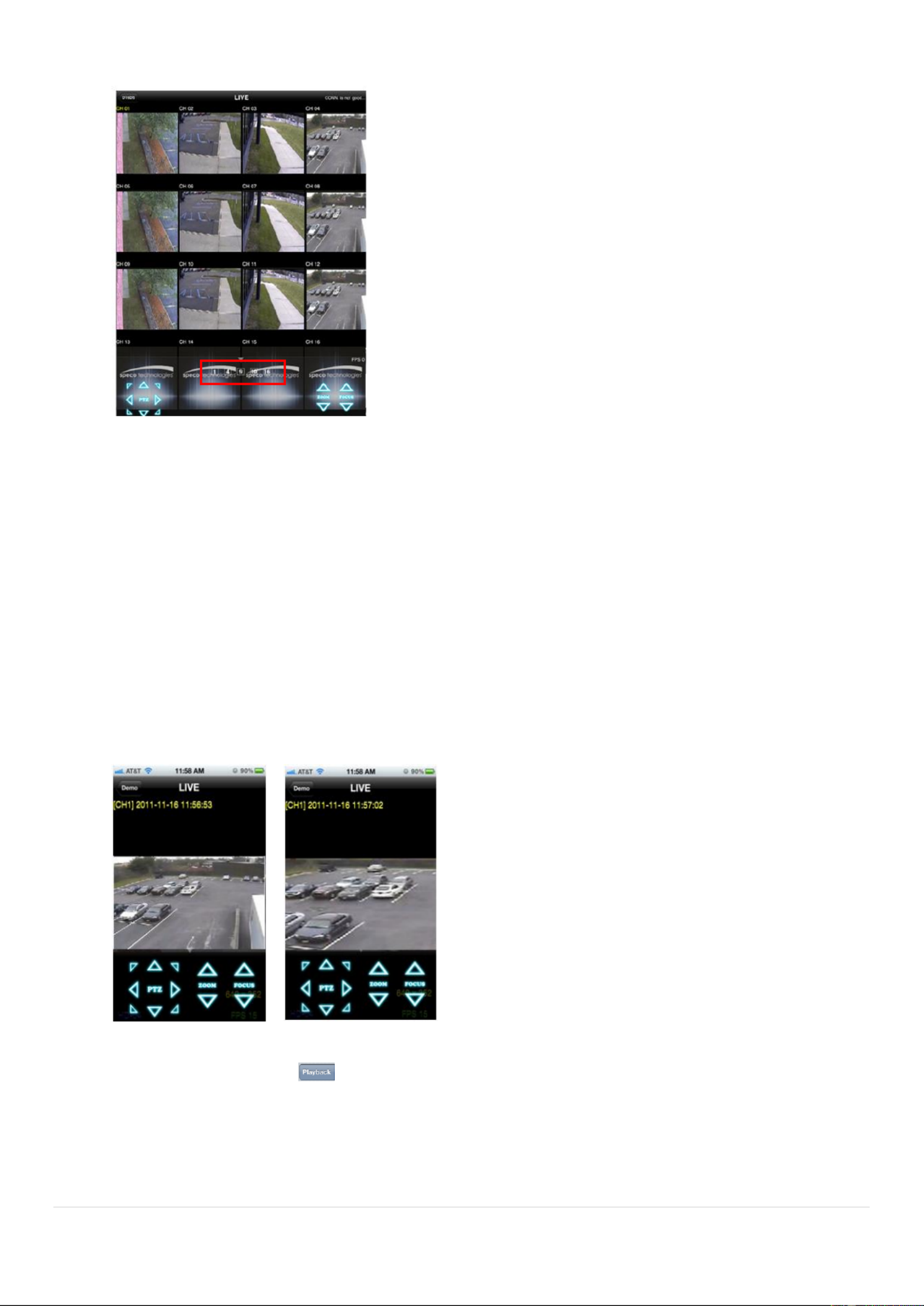
3. Select a registered device and select LIVE. Then click “CONNECT buon. ”
4. The app will display the selected channel(s). Double tap the channel screen to switch 1 channel display to 4,
8, 10, channels split display depending on the DVR. 16
Notice
SPECO Player for the DS, RS, WRS and HD series . SPECO VIEWER is not is DVRs
compatible with the T Series DVR‟s (TH, TN or TL) or the PC Series DVR‟s.
91
5. To select the display mode(1, 4, 9, 10 or 16 split display), tap the arrow menus buon
6. Drag and drop channels
Touch and drag one channel to the other channel to swap the channel locaon. To swap the channel, drag a
channel to another channel.
7. Digital Zoom In-Out
Double tap on the desired channel to view in 1channel mode. Then use the iPhone zoom feature using two
ngers to pinch the screen to zoom in or out on the video image. User can also move the zoomed image
around by touching the desired spot and dragging the zoom image.
9-1-2.PTZ Control
To control the PTZ funcons of the camera, tap the menu buon. Then PTZ menu icons will display. Using the PTZ
icon on the screen, control PTZF control.
9-1-3. Playback
1. Select Mode as ‘Playback’ and click ‘ CONNECT buon. Then select Date & Time and click PLAY buon. ’

93
9-2-1. Live
1. Open the installed “Speco Player” App and select the Live Preview. Then click the menu buon of the phone
to add a remote device.
2. Select the registered device and select LIVE VIEW and select up to 4 channels to monitor. Then click START
buon.
3. The app will display the selected channel(s). Double tap the channel screen to switch 1 channel display to 4
channels split display.
9-2- Playback 2.
1. Select the registered device and select PLAYBACK and select up to 4 channels to search. Then click START
buon.
2. The app will display the selected channel(s). Double tap the channel screen to switch 1 channel display to 4
channels split display.

94
9-2-3.PTZ Control
To control the PTZ funcon of the camera, tap the channel screen, then the channel name will be highlighted
in Yellow. Using the PTZ menu icons on the screen, control PTZF.

95
APPENDIX: Network Connection - LAN
1. Install the network client software from the supplied CD.
2. Check the IP address from SETUP > SYSTEM > DESCRIPTION or SETUP>NETWORK of DVR.
3. Run the network client software.

96
4. Input Site Name, Site Address (IP address), Port Number, and Password on the connect window.
Input a name that properly describes a site. Site Name:
IP Address: Input IP address
Port Number: Default Port Number is “5445”.
Input ID of DVR. ID: Default ID is “admin”.
Input network password of DVR. Password: Default Password is “1111”.
5. Select a site by checking the box, and Press button to connect to the site .
Specyfikacje produktu
| Marka: | Speco Technologies |
| Kategoria: | Kamera monitorująca |
| Model: | D16WDS |
Potrzebujesz pomocy?
Jeśli potrzebujesz pomocy z Speco Technologies D16WDS, zadaj pytanie poniżej, a inni użytkownicy Ci odpowiedzą
Instrukcje Kamera monitorująca Speco Technologies

12 Stycznia 2025
12 Stycznia 2025
11 Stycznia 2025
22 Września 2024
20 Września 2024
20 Września 2024
18 Września 2024
18 Września 2024
18 Września 2024
18 Września 2024
Instrukcje Kamera monitorująca
- Kamera monitorująca Sony
- Kamera monitorująca Samsung
- Kamera monitorująca Tenda
- Kamera monitorująca Motorola
- Kamera monitorująca Stabo
- Kamera monitorująca Logitech
- Kamera monitorująca Xiaomi
- Kamera monitorująca Braun
- Kamera monitorująca Pioneer
- Kamera monitorująca TP-Link
- Kamera monitorująca Philips
- Kamera monitorująca Bosch
- Kamera monitorująca Gigaset
- Kamera monitorująca Hikvision
- Kamera monitorująca EZVIZ
- Kamera monitorująca Conceptronic
- Kamera monitorująca Panasonic
- Kamera monitorująca Canon
- Kamera monitorująca Crestron
- Kamera monitorująca Withings
- Kamera monitorująca Asus
- Kamera monitorująca Nedis
- Kamera monitorująca AG Neovo
- Kamera monitorująca Reolink
- Kamera monitorująca Boss
- Kamera monitorująca TRENDnet
- Kamera monitorująca Marquant
- Kamera monitorująca Toshiba
- Kamera monitorująca D-Link
- Kamera monitorująca August
- Kamera monitorująca Niceboy
- Kamera monitorująca Ring
- Kamera monitorująca Garmin
- Kamera monitorująca Imou
- Kamera monitorująca Blaupunkt
- Kamera monitorująca Grundig
- Kamera monitorująca APC
- Kamera monitorująca Honeywell
- Kamera monitorująca BLOW
- Kamera monitorująca Manhattan
- Kamera monitorująca Strong
- Kamera monitorująca Swann
- Kamera monitorująca Kwikset
- Kamera monitorująca Kodak
- Kamera monitorująca Cisco
- Kamera monitorująca ORNO
- Kamera monitorująca Broan
- Kamera monitorująca Moxa
- Kamera monitorująca Synology
- Kamera monitorująca Gembird
- Kamera monitorująca ZTE
- Kamera monitorująca Turing
- Kamera monitorująca Lindy
- Kamera monitorująca Minox
- Kamera monitorująca Zebra
- Kamera monitorująca DSC
- Kamera monitorująca JVC
- Kamera monitorująca ZyXEL
- Kamera monitorująca Trust
- Kamera monitorująca LogiLink
- Kamera monitorująca Furrion
- Kamera monitorująca Linksys
- Kamera monitorująca Google
- Kamera monitorująca Digitus
- Kamera monitorująca Vimar
- Kamera monitorująca V-TAC
- Kamera monitorująca Dahua Technology
- Kamera monitorująca Schneider
- Kamera monitorująca Eufy
- Kamera monitorująca Ricoh
- Kamera monitorująca Emos
- Kamera monitorująca AVMATRIX
- Kamera monitorująca Renkforce
- Kamera monitorująca Rollei
- Kamera monitorująca Marshall
- Kamera monitorująca Perel
- Kamera monitorująca Somfy
- Kamera monitorująca Uniden
- Kamera monitorująca Netgear
- Kamera monitorująca Thomson
- Kamera monitorująca DiO
- Kamera monitorująca Velleman
- Kamera monitorująca Ferguson
- Kamera monitorująca DataVideo
- Kamera monitorująca Delta Dore
- Kamera monitorująca Pyle
- Kamera monitorująca Intellinet
- Kamera monitorująca CRUX
- Kamera monitorująca Setti+
- Kamera monitorująca Waeco
- Kamera monitorująca Vivotek
- Kamera monitorująca Vtech
- Kamera monitorująca EtiamPro
- Kamera monitorująca Edimax
- Kamera monitorująca Petcube
- Kamera monitorująca ION
- Kamera monitorująca First Alert
- Kamera monitorująca AirLive
- Kamera monitorująca Maginon
- Kamera monitorująca EnGenius
- Kamera monitorująca SPC
- Kamera monitorująca Planet
- Kamera monitorująca Brilliant
- Kamera monitorująca Genie
- Kamera monitorująca LevelOne
- Kamera monitorująca Axis
- Kamera monitorująca Sanyo
- Kamera monitorująca Lorex
- Kamera monitorująca Control4
- Kamera monitorująca Milesight
- Kamera monitorująca Aluratek
- Kamera monitorująca Abus
- Kamera monitorująca Elro
- Kamera monitorująca Olympia
- Kamera monitorująca Hama
- Kamera monitorująca Marmitek
- Kamera monitorująca Ubiquiti Networks
- Kamera monitorująca Western Digital
- Kamera monitorująca Netatmo
- Kamera monitorująca Schwaiger
- Kamera monitorująca Promise Technology
- Kamera monitorująca GVI Security
- Kamera monitorująca AVer
- Kamera monitorująca ZKTeco
- Kamera monitorująca Netis
- Kamera monitorująca Extech
- Kamera monitorująca Denver
- Kamera monitorująca Anker
- Kamera monitorująca Allnet
- Kamera monitorująca Marshall Electronics
- Kamera monitorująca Orion
- Kamera monitorująca Yale
- Kamera monitorująca SereneLife
- Kamera monitorująca Ernitec
- Kamera monitorująca AVerMedia
- Kamera monitorująca MEE Audio
- Kamera monitorująca Genius
- Kamera monitorująca Trevi
- Kamera monitorująca Technaxx
- Kamera monitorująca Atlona
- Kamera monitorująca Hanwha
- Kamera monitorująca Overmax
- Kamera monitorująca Quantum
- Kamera monitorująca Y-cam
- Kamera monitorująca Grandstream
- Kamera monitorująca Raymarine
- Kamera monitorująca Powerfix
- Kamera monitorująca Avanti
- Kamera monitorująca Ikan
- Kamera monitorująca Alecto
- Kamera monitorująca Avidsen
- Kamera monitorująca JUNG
- Kamera monitorująca Burg Wächter
- Kamera monitorująca Foscam
- Kamera monitorująca Lumens
- Kamera monitorująca Monacor
- Kamera monitorująca Dörr
- Kamera monitorująca M-e
- Kamera monitorująca EVE
- Kamera monitorująca Smartwares
- Kamera monitorująca Adj
- Kamera monitorująca Qian
- Kamera monitorująca Arenti
- Kamera monitorująca Elmo
- Kamera monitorująca Vitek
- Kamera monitorująca Alfatron
- Kamera monitorująca UniView
- Kamera monitorująca Clas Ohlson
- Kamera monitorująca Laserliner
- Kamera monitorująca Megasat
- Kamera monitorująca REVO
- Kamera monitorująca BZBGear
- Kamera monitorująca BirdDog
- Kamera monitorująca KJB Security Products
- Kamera monitorująca HiLook
- Kamera monitorująca Profile
- Kamera monitorująca Aldi
- Kamera monitorująca Aritech
- Kamera monitorująca Acti
- Kamera monitorująca ACME
- Kamera monitorująca Flamingo
- Kamera monitorująca Caliber
- Kamera monitorująca Eminent
- Kamera monitorująca Sitecom
- Kamera monitorująca Exibel
- Kamera monitorująca Fortinet
- Kamera monitorująca KlikaanKlikuit
- Kamera monitorująca Trebs
- Kamera monitorująca Ednet
- Kamera monitorująca Steren
- Kamera monitorująca Flir
- Kamera monitorująca Buffalo
- Kamera monitorująca Arlo
- Kamera monitorująca Nest
- Kamera monitorująca Siedle
- Kamera monitorująca Hive
- Kamera monitorująca Switel
- Kamera monitorująca Chacon
- Kamera monitorująca InFocus
- Kamera monitorująca Hombli
- Kamera monitorująca Naxa
- Kamera monitorująca Konig
- Kamera monitorująca Valueline
- Kamera monitorująca BRK
- Kamera monitorująca QSC
- Kamera monitorująca Xavax
- Kamera monitorująca Vaddio
- Kamera monitorująca Gira
- Kamera monitorująca Interlogix
- Kamera monitorująca Boyo
- Kamera monitorująca IC Intracom
- Kamera monitorująca Iget
- Kamera monitorująca EverFocus
- Kamera monitorująca Adesso
- Kamera monitorująca Satel
- Kamera monitorująca POSline
- Kamera monitorująca Notifier
- Kamera monitorująca Hawking Technologies
- Kamera monitorująca Friedland
- Kamera monitorująca Nexxt
- Kamera monitorująca Monoprice
- Kamera monitorująca Watec
- Kamera monitorująca Beafon
- Kamera monitorująca Chuango
- Kamera monitorująca ETiger
- Kamera monitorująca Videcon
- Kamera monitorująca INSTAR
- Kamera monitorująca Provision ISR
- Kamera monitorująca Aqara
- Kamera monitorująca Advantech
- Kamera monitorująca Digital Watchdog
- Kamera monitorująca Ganz
- Kamera monitorująca AViPAS
- Kamera monitorująca ClearOne
- Kamera monitorująca Ebode
- Kamera monitorująca Oplink
- Kamera monitorująca Sonic Alert
- Kamera monitorująca Linear PRO Access
- Kamera monitorująca Summer Infant
- Kamera monitorująca SMC
- Kamera monitorująca Topica
- Kamera monitorująca Kogan
- Kamera monitorująca Iiquu
- Kamera monitorująca Verint
- Kamera monitorująca Brinno
- Kamera monitorująca Rostra
- Kamera monitorująca Caddx
- Kamera monitorująca Spyclops
- Kamera monitorująca EKO
- Kamera monitorująca Kguard
- Kamera monitorująca Woonveilig
- Kamera monitorująca Mobi
- Kamera monitorująca Surveon
- Kamera monitorująca Hollyland
- Kamera monitorująca Epcom
- Kamera monitorująca Indexa
- Kamera monitorująca Lutec
- Kamera monitorująca Whistler
- Kamera monitorująca ClearView
- Kamera monitorująca VideoComm
- Kamera monitorująca IMILAB
- Kamera monitorująca 3xLOGIC
- Kamera monitorująca Pelco
- Kamera monitorująca Leviton
- Kamera monitorująca Inkovideo
- Kamera monitorująca Pentatech
- Kamera monitorująca Weldex
- Kamera monitorująca SecurityMan
- Kamera monitorująca Canyon
- Kamera monitorująca CNB Technology
- Kamera monitorująca Tapo
- Kamera monitorująca Aigis
- Kamera monitorująca Exacq
- Kamera monitorująca Brickcom
- Kamera monitorująca Laxihub
- Kamera monitorująca Securetech
- Kamera monitorująca EFB Elektronik
- Kamera monitorująca NetMedia
- Kamera monitorująca Videotec
- Kamera monitorująca Illustra
- Kamera monitorująca Nivian
- Kamera monitorująca E-bench
- Kamera monitorująca Syscom
- Kamera monitorująca Tecno
- Kamera monitorująca Night Owl
- Kamera monitorująca Guardzilla
- Kamera monitorująca Astak
- Kamera monitorująca Blink
- Kamera monitorująca Milestone Systems
- Kamera monitorująca Zavio
- Kamera monitorująca Campark
- Kamera monitorująca IPX
- Kamera monitorująca Dedicated Micros
- Kamera monitorująca Hamlet
- Kamera monitorująca Annke
- Kamera monitorująca AVTech
- Kamera monitorująca Qoltec
- Kamera monitorująca Approx
- Kamera monitorująca Digimerge
- Kamera monitorująca Wisenet
- Kamera monitorująca Infortrend
- Kamera monitorująca Epiphan
- Kamera monitorująca Mach Power
- Kamera monitorująca Compro
- Kamera monitorująca Aida
- Kamera monitorująca Ikegami
- Kamera monitorująca Accsoon
- Kamera monitorująca Vimtag
- Kamera monitorująca Gewiss
- Kamera monitorująca Alula
- Kamera monitorująca Insteon
- Kamera monitorująca Costar
- Kamera monitorująca ALC
- Kamera monitorująca Security Labs
- Kamera monitorująca Comtrend
- Kamera monitorująca Seneca
- Kamera monitorująca Avigilon
- Kamera monitorująca American Dynamics
- Kamera monitorująca Vosker
- Kamera monitorująca Sentry360
- Kamera monitorująca Bea-fon
- Kamera monitorująca Owltron
- Kamera monitorująca Enabot
- Kamera monitorująca Luis Energy
- Kamera monitorująca Sir Gawain
- Kamera monitorująca VisorTech
- Kamera monitorująca Atlantis Land
- Kamera monitorująca B & S Technology
- Kamera monitorująca I3International
- Kamera monitorująca IDIS
- Kamera monitorująca Ecobee
- Kamera monitorująca Conbrov
- Kamera monitorująca HuddleCamHD
- Kamera monitorująca Mobotix
- Kamera monitorująca IOIO
- Kamera monitorująca BIRDFY
- Kamera monitorująca I-PRO
- Kamera monitorująca DVDO
- Kamera monitorująca TCP
- Kamera monitorująca Bolin Technology
- Kamera monitorująca Nextech
Najnowsze instrukcje dla Kamera monitorująca
28 Stycznia 2025
25 Stycznia 2025
17 Stycznia 2025
17 Stycznia 2025
15 Stycznia 2025

13 Stycznia 2025

13 Stycznia 2025
13 Stycznia 2025

12 Stycznia 2025
12 Stycznia 2025