Instrukcja obsługi Smart-AVI DVX-PLUS
Smart-AVI
przedłużacz AV
DVX-PLUS
Przeczytaj poniżej 📖 instrukcję obsługi w języku polskim dla Smart-AVI DVX-PLUS (2 stron) w kategorii przedłużacz AV. Ta instrukcja była pomocna dla 8 osób i została oceniona przez 2 użytkowników na średnio 4.5 gwiazdek
Strona 1/2
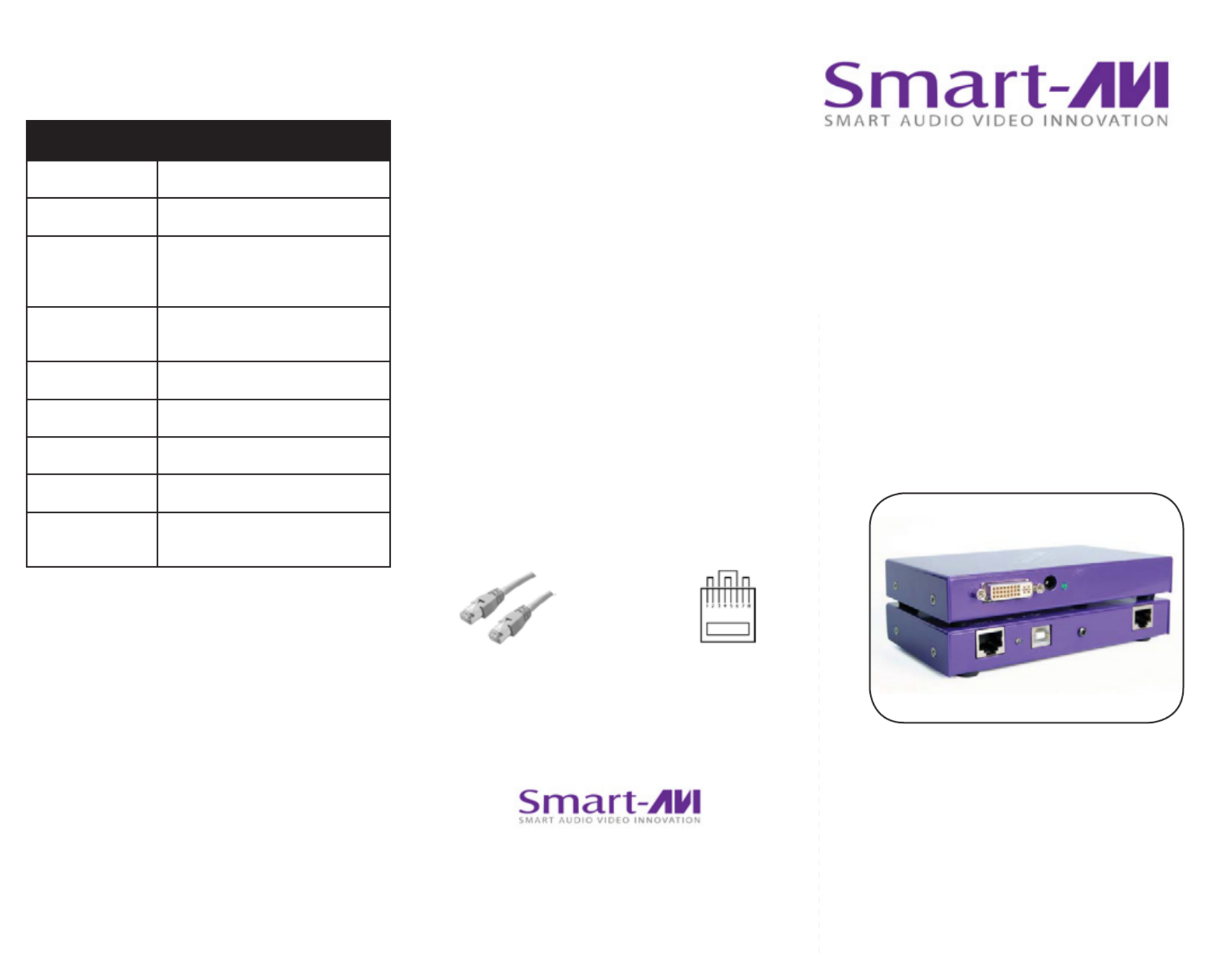
DVI-D and USB extension
via Twisted Pair
DVX Plus
www.smartavi.com
© Copyright 2012 Smart-AVI, All Rights Reserved
Notice
The information contained in this document is
subject to change without notice. Smart-AVI makes
no warranty of any kind with regard to this material,
including but not limited to, implied warranties of
merchantability and tness for any particular purpose.
Smart-AVI will not be liable for errors contained herein or
for incidental or consequential damages in connection
with the furnishing, performance or use of this material.
No part of this document may be photocopied,
reproduced or translated into another language without
prior written consent from Smart-AVI.
For more information, visit www.smartavi.com.
www.smartavi.com
Installation
Manual
SmartAVI, Inc. / Twitter: smartavi
11651 Vanowen St., North Hollywood, CA 91605
Tel: (818) 503-6200 Fax: (818) 503-6208
http://www.SmartAVI.com
The following is the wiring standard for terminating UTP/STP
cable using RJ-45 connector:
Connectors: RJ-45
Capacitance: 14 pf/ft (46.2 pf/m)
Conductor Gauge: 24 AWG
Impedance: 100 +/- 15 ohms
Pair 1 Pins 1 & 2
Pair 2 Pins 3 & 6
Pair 3 Pins 4 & 5
Pair 4 Pins 7 & 8
DVX PLUS SPECIFICATIONS
Video Interface Single Link Range
Video Data Rate 1.65 Gbps
Resolution
1920 x 1200 @ 60 Hz, Reso
lution up to 1280 x 1024
min. 75H
Power Supply Universal Switch mode PSU
(90-240V Input) 5VDC 4A
Input Interface DVI-D
USB Data
USB max data rate 12Mbps
USB compatibility 1.0 and 1.1
Connector Type Type A (Transmitter)
Type B (Receiver)
Technical Specifications

Introduction
Preparing & Connecting System CAT5 Cable
Following is the wiring standard for terminating CAT 5 cable
using RJ-45 connector:
Pair 1 Pins 1 & 2
Pair 2 Pins 3 & 6
Pair 3 Pins 4 & 5
Pair 4 Pins 7 & 8
Connectors: RJ-45
Capacitance: 14 pf/ft (46.2 pf/m)
Conductor Gauge: 24 AWG
Impedance: 100 +/- 15 ohms
4 - Pair
Operating Instructions
Once installation is completed verify that the power is
present at all devices in the system. If computer was on
during the set up it might be necessary to reboot the
computer. The peripheral devices should be ready for
use.
Connecting The Transmitter
Connect the transmitter to the host using an A-B 1.
USB cable.
Connect the transmitter to the host DVI-D using 2.
male to male DVI cable.
The A side of the USB connector would go to the 3.
computer host and the B side would be connected
to the transmitter.
Check that power LED is lit. The TX/RX LED should 4.
not be flashing at this time.
In the back of the unit connect the CAT5 cable that 5.
will connect to the receiver (DVXU-RX).
Connecting The Receiver
Connect the receiver to the peripheral device using 1.
A-B USB cable. In this case the A side of the connec-
tor will go to the receiver unit and the B side of the
connector will go the peripheral. Use a USB Hub if
needed.
Connect the receiver unit to the monitor.2.
Join the DVX Plus units using shielded cable for 3.
DVI-D and standard CAT5/6 UTP cable for USB.
Once connected check that the Power LED on both
receiver and transmitter is on and the TX/RX LED is
flashing, indicating that communication exists be-
tween the two units. If receiver LED is not on, make
sure the power supply is connected.
Installation Diagram
AB
Setting the DDC
DDC provides plug-and-play capability to your
displays. When you plug a display into your computer,
the DDC table in the display tells the computer the
optimal resolution to use. This device is capable of
supporting two primary types of displays: PC and Mac.
The default setting is PC.
For Mac, congure the
switches as shown below:
For PC, congure the
switches as shown below:
1&2 ON, 3&4 OFF 1&2 OFF, 3&4 ON
To change this setting,
rst remove the top cover
from the TRANSMITTER
by removing the four side
screws. Next, locate the
DIP switches near the rear
of the device next to the
Data Port (RJ45 Ethernet
Port).
STP
STP6
Introduction
DVX Plus extends Universal Serial Bus (USB 1.1) and
Digital Visual Interface (DVI-D) signals via com-
mon twisted pair cable. Using a unique method of
transparent data transfer, the system allows a USB
peripheral and a DVI display to be located up to 225
feet from the CPU.
Features
• Extends USB and DVI-D signals up to 225ft from
the computer.
• Uses easy to install, inexpensive twisted pair cable.
• Data recovery for digital video.
• Supports 1920x1200 digital video resolution.
• Fully compliant with USB 1.1 specifications.
• Supports 1.5 and 12 Mbps data rates.
• Compatible with all operating systems.
• External power adapter for transmitter and re-
ceiver unit.
• Fully transparent (does not use any emulation).
• Plug and play.
DVX Plus Package Contents
Qty Items Part No.
1 DVX Plus Transmitter unit DVXU-TX
1 DVX Plus Receiver unit DVXU-RX
2 5 volt dc power supply PS-5D4A-US
Connecting The Transmitter
1. Connect the transmitter to the host using an A-B USB
cable.
2. Connect the transmitter to the host DVI-D using male
to male DVI cable.
3. The A side of the USB connector would go to the
computer host and the B side would be connected to
the transmitter.
4. Check that power LED is lit. The TX/RX LED should not
be ashing at this time.
5. In the back of the unit connect the CAT5 cable that will
connect to the receiver (DVXU-RX).
Connecting The Receiver
1. Connect the receiver to the peripheral device using A-B
USB cable. In this case the A side of the connector will
go to the receiver unit and the B side of the connector
will go the peripheral. Use a USB Hub if needed.
2. Connect the receiver unit to the monitor.
3. Join the DVX Plus units using shielded cable for DVI-D
and standard CAT6 STP cable for USB. Once con-
nected check that the Power LED on both receiver and
transmitter is on and the , indicating RX LED goes OFF
that communication exists between the two units. If
receiver LED is not on, make sure the power supply is
connected.
AB
Specyfikacje produktu
| Marka: | Smart-AVI |
| Kategoria: | przedłużacz AV |
| Model: | DVX-PLUS |
Potrzebujesz pomocy?
Jeśli potrzebujesz pomocy z Smart-AVI DVX-PLUS, zadaj pytanie poniżej, a inni użytkownicy Ci odpowiedzą
Instrukcje przedłużacz AV Smart-AVI

9 Stycznia 2025
9 Stycznia 2025
3 Stycznia 2025
1 Stycznia 2025
1 Stycznia 2025
1 Stycznia 2025
1 Stycznia 2025
1 Stycznia 2025
1 Stycznia 2025
1 Stycznia 2025
Instrukcje przedłużacz AV
- przedłużacz AV Philips
- przedłużacz AV Gigabyte
- przedłużacz AV Roland
- przedłużacz AV KEF
- przedłużacz AV StarTech.com
- przedłużacz AV Crestron
- przedłużacz AV Nedis
- przedłużacz AV AG Neovo
- przedłużacz AV D-Link
- przedłużacz AV ATen
- przedłużacz AV Manhattan
- przedłużacz AV Tripp Lite
- przedłużacz AV Dynaudio
- przedłużacz AV Lindy
- przedłużacz AV LogiLink
- przedłużacz AV Digitus
- przedłużacz AV Oehlbach
- przedłużacz AV AVMATRIX
- przedłużacz AV Renkforce
- przedłużacz AV Adder
- przedłużacz AV DataVideo
- przedłużacz AV One For All
- przedłużacz AV Black Box
- przedłużacz AV Pyle
- przedłużacz AV Iogear
- przedłużacz AV Intellinet
- przedłużacz AV Vivotek
- przedłużacz AV Peerless-AV
- przedłużacz AV Audio Pro
- przedłużacz AV Kindermann
- przedłużacz AV Bogen
- przedłużacz AV Edimax
- przedłużacz AV Planet
- przedłużacz AV Blustream
- przedłużacz AV LevelOne
- przedłużacz AV Vivolink
- przedłużacz AV Teufel
- przedłużacz AV Vision
- przedłużacz AV Abus
- przedłużacz AV Rocstor
- przedłużacz AV Hama
- przedłużacz AV Marmitek
- przedłużacz AV Schwaiger
- przedłużacz AV Micro Connect
- przedłużacz AV Allnet
- przedłużacz AV Marshall Electronics
- przedłużacz AV AJA
- przedłużacz AV Trevi
- przedłużacz AV Atlona
- przedłużacz AV Gefen
- przedłużacz AV SEADA
- przedłużacz AV Monacor
- przedłużacz AV I3-Technologies
- przedłużacz AV Lightware
- przedłużacz AV Alfatron
- przedłużacz AV Megasat
- przedłużacz AV Speaka
- przedłużacz AV Belkin
- przedłużacz AV SWIT
- przedłużacz AV Sescom
- przedłużacz AV Kramer
- przedłużacz AV KanexPro
- przedłużacz AV Kopul
- przedłużacz AV Analog Way
- przedłużacz AV Apantac
- przedłużacz AV AMX
- przedłużacz AV C2G
- przedłużacz AV Act
- przedłużacz AV Eminent
- przedłużacz AV Techly
- przedłużacz AV Matrox
- przedłużacz AV Steren
- przedłużacz AV InFocus
- przedłużacz AV Konig
- przedłużacz AV Dune
- przedłużacz AV Genexis
- przedłużacz AV Wentronic
- przedłużacz AV Peerless
- przedłużacz AV Monoprice
- przedłużacz AV WyreStorm
- przedłużacz AV TV One
- przedłużacz AV MIPRO
- przedłużacz AV Provision ISR
- przedłużacz AV UTEPO
- przedłużacz AV Aitech
- przedłużacz AV SIIG
- przedłużacz AV Polycom
- przedłużacz AV Advantech
- przedłużacz AV Intelix
- przedłużacz AV MuxLab
- przedłużacz AV Extron
- przedłużacz AV ASSMANN Electronic
- przedłużacz AV Avocent
- przedłużacz AV Comprehensive
- przedłużacz AV Rose
- przedłużacz AV Ebode
- przedłużacz AV Accell
- przedłużacz AV Ecler
- przedłużacz AV Rose Electronics
- przedłużacz AV Epcom
- przedłużacz AV CYP
- przedłużacz AV SmartAVI
- przedłużacz AV IMG Stage Line
- przedłużacz AV HELGI
- przedłużacz AV Liberty
- przedłużacz AV PureTools
- przedłużacz AV Enson
- przedłużacz AV Approx
- przedłużacz AV Hall Research
- przedłużacz AV Seco-Larm
- przedłużacz AV ConnectPro
- przedłużacz AV Kanex
- przedłużacz AV TechLogix Networx
- przedłużacz AV PureLink
- przedłużacz AV DVDO
- przedłużacz AV Camplex
Najnowsze instrukcje dla przedłużacz AV
8 Kwietnia 2025
1 Kwietnia 2025
1 Kwietnia 2025
1 Kwietnia 2025
1 Kwietnia 2025
1 Kwietnia 2025
26 Lutego 2025
20 Lutego 2025
20 Lutego 2025
7 Lutego 2025