Instrukcja obsługi Provision ISR SH-4050A-4
Provision ISR
Rejestrator głosu
SH-4050A-4
Przeczytaj poniżej 📖 instrukcję obsługi w języku polskim dla Provision ISR SH-4050A-4 (113 stron) w kategorii Rejestrator głosu. Ta instrukcja była pomocna dla 12 osób i została oceniona przez 2 użytkowników na średnio 4.5 gwiazdek
Strona 1/113

1
1
Notes
Please read this user manual carefully to ensure that you use the device correctly and
safely.
There may be incorrect info or printing errors in this manual. Updates and corrections will
be made into the future versions of this manual. The content of this manual subject to change is
without notice.
The device should be operated using only the type of power source indicated on the
marking label. The power voltage must be verified before use.
Do not install this device near any heat sources such as radiators, heat registers, stoves or
other devices that produce heat.
Do not install this device near water.
Clean only with a dry cloth.
Do not block any ventilation openings and ensure proper ventilation around the device.
Perform a safe power off before disconnecting from power.
This device is for indoor use only. Do not expose it to rainy or moist environments. In case
any solid or liquid get inside the device’s case, turn off the device immediately and get it
checked by a qualified technician.
Do not try to repair the device by yourself without technical aid or approval.
When this device is in use, the relevant contents of Microsoft, Apple and Google be may
shown. The ownerships of trademarks, logos and other intellectual properties related to
Microsoft, Apple and Google shall belong to the above-mentioned companies.
This manual is suitable for all /DVR models running Ossia OS. Clear markings will NVR
be made if some models do not support any of the features. All examples and pictures used in
the manual are from one of the models for reference purpose.
For devices with internal power supply, please make sure that the AC 220/110V input
selector is set correctly

Basic Operation Guide User Manual
2
Contents
Contents ..................................................................................................................................... 2
1 Introduction ................................................................................................................... 6
1.1 Summary ....................................................................................................................... 6
1.2 Features ......................................................................................................................... 6
1.3 Front Panel Descriptions ............................................................................................... 9
1.4 Rear Panel Descriptions .............................................................................................. 10
1.5 Connections ................................................................................................................. 12
2 Basic Operations Guide .............................................................................................. 14
2.1 Startup & Shutdown .................................................................................................... 14
2.1.1 Startup .............................................................................................................. 14
2.1.2 Shutdown 14.........................................................................................................
2.2 Remote Controller ....................................................................................................... 15
2.3 Mouse Control ............................................................................................................. 16
2.4 Text-input Instruction .................................................................................................. 16
2.5 Other Button Operations ............................................................................................. 16
3 Wizard & Main Interface ........................................................................................... 17
3.1 Startup Wizard ............................................................................................................. 17
3.2 Main Interface ............................................................................................................. 24
3.2.1 Main Interface Introduction .............................................................................. 24
3.2.2 Setup Panel ....................................................................................................... 26
3.2.3 Main Functions ................................................................................................. 27
4 Camera Management .................................................................................................. 29
4.1 Camera Signal (Applicable only for DVRs) ................................................................ 29
4.2 Add/Edit Camera ......................................................................................................... 29
4.2.1 Add Camera
(Applicable only for NVRs and Hybrid DVR models) .............. 29
4.2.2 Edit Camera’s General Parameters ................................................................... 32
4.3 -“In Channel Sequence” (Only Applicable for NVRs) ................................................. 34
4.3.1 Add “In Channel Sequence”- ............................................................................. 34
4.3.2 Edit -Channel Sequence In ................................................................................ 34
4.4 IPC Networking (Applicable only for NVRs and Hybrid DVR models) 35....................
4.4.1 IP Camera management .................................................................................... 35
4.4.2 Device Management ......................................................................................... 36
5 Live-view Introduction: .............................................................................................. 37
5.1 Live-View Interfaces: .................................................................................................. 37
5.2 Live View Digital Zoom: 38............................................................................................
5.3 Live-View Modes: ....................................................................................................... 39
5.3.1 Customized Display Mode ............................................................................... 39
5.3.2 Sequence .......................................................................................................... 40
5.3.3 In Channel Sequence (Applicable for NVRs only). .......................................... 41
5.4 Emergency Live-View: 42................................................................................................
5.5 Image Configuration ................................................................................................... 42
5.5.1 OSD Settings .................................................................................................... 42

Basic Operation Guide User Manual
3
5.5.2 Image Settings (Setting Interface) .................................................................... 42
5.5.3 Mask Settings ................................................................................................... 43
5.5.4 Water Mark Settings (Applicable for DVRs only) ............................................ 44
5.5.5 Image Adjustment (Live-View Interface) ......................................................... 45
6 PTZ ............................................................................................................................... 47
6.1 PTZ Control Interface: ................................................................................................ 47
6.2 Preset Settings ............................................................................................................. 49
7 Record & Disk Management ...................................................................................... 51
7.1 Record Configuration: ................................................................................................. 51
7.1.1 Mode Configuration: ........................................................................................ 51
7.1.2 Advanced Configuration ................................................................................... 53
7.2 Encode Parameters Setting .......................................................................................... 54
7.3 Schedule Setting .......................................................................................................... 55
7.3.1 Add Schedule 55...................................................................................................
7.3.2 Record Schedule Configuration 57........................................................................
7.4 Record Mode ............................................................................................................... 57
7.4.1 Manual Recording ............................................................................................ 57
7.4.2 Scheduled Recording: ....................................................................................... 58
7.4.3 Motion Based Recording: ................................................................................. 58
7.4.4 Sensor Based Recording: .................................................................................. 58
7.4.5 Analytics Based Recording: 58.............................................................................
7.5 Disk Management: ...................................................................................................... 58
7.5.1 Storage Mode Configuration ............................................................................ 59
7.5.2 View Disk and S.M.A.R.T. Information ........................................................... 60
8 Search, Playback & Backup ....................................................................................... 61
8.1 Instant Playback .......................................................................................................... 61
8.2 Playback Interface Introduction .................................................................................. 61
8.3 Record Search, Playback & Backup ............................................................................ 64
8.3.1 Search & Playback by Time-sliced Image ........................................................ 64
8.3.2 Search Playback & Backup by Time: , .............................................................. 66
8.3.3 Search, Backup & Playback by Event .............................................................. 67
8.3.4 Search & Playback by Tag ................................................................................ 67
8.3.5 Snapshots 68.........................................................................................................
8.3.6 Backup Procedures ........................................................................................... 68
8.3.7 View Backup Status .......................................................................................... 69
9 Alarm Management .................................................................................................... 70
9.1 Sensor Alarm ............................................................................................................... 70
9.2 Motion Alarm .............................................................................................................. 71
9.2.1 Motion Configuration ....................................................................................... 71
9.2.2 Motion Alarm Handling Configuration ............................................................ 72
9.3 Analytics Configuration (Applicable for NVRs and Hybrid DVRs only). .................. 72
9.3.1 Object Monitoring Configuration ..................................................................... 73
9.3.2 Camera Tampering Configuration .................................................................... 74
9.3.3 Line Crossing Configuration ............................................................................ 75
9.3.4 Sterile Area Configuration ................................................................................ 76
9.3.5 Analytics Alarm Handling Configuration ......................................................... 76
Basic Operation Guide User Manual
9
1.3 Front Panel Descriptions
The following descriptions are for reference only.
Type I (MM/Small 1U/1.5U Models):
Name
Descriptions
REC
While recording, the light is blue
NET
When accessed by network the light is blue
PWR
When powered on , the light is blue
Type II (2U Models):
Name
Descriptions
Power
When powered on, the light is blue
HDD
The light turns blue when reading/writing HDD
Net
The light turns blue when the devices access the network es
Backup
The light turns blue when backing up files and data
Play
The light turns blue when playing back video
REC
When recording, the light is blue
AUDIO /+
1. Adjust audio; 2. Increase the value in set up
P.T.Z / -
1. Enter PTZ mode; 2. Decrease the value in setup
MENU
Enter Menu
INFO
Check the information of the device
BACKUP
Enter backup mode in live
SEARCH
Enter search mode in live
Exit
Exit the current interface
Manual record
Play/Pa use
Speed down
Speed up
1-9
Input digital number and select camera
0/--
Input number 0, the number above 10
Direction Key
Change direction
Multi-Screen Switch
Change the screen mode
Enter
Confirm selection
USB
To connect external USB device like USB mouse or USB
flash
Basic Operation Guide User Manual
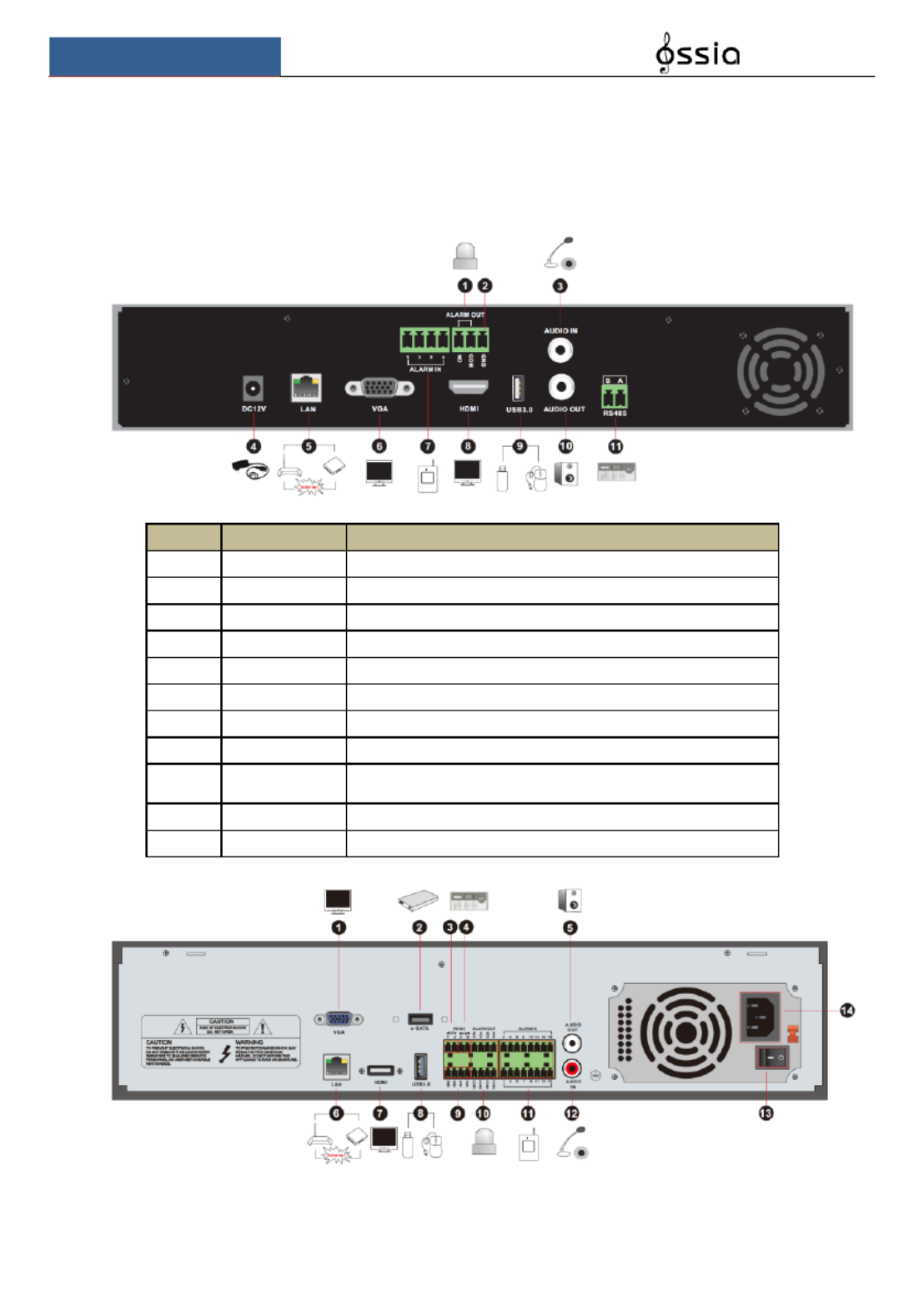
10
1.4 Rear Panel Descriptions
In this section we will introduce you to a few samples of rear panels. Of course we cannot
include all rear panels of all the available devices. Please take this manual as reference only.
No.
Name
Descriptions
1
ALARM OUT
Relay output; connect to external devices
2
GND
Ground connection
3
AUDIO IN
Audio input
4
DC12V
DC12V power input
5
LAN
Network port
6
VGA
Connect to VGA monitor
7
ALARM IN
Alarm inputs for connecting sensors
8
HDMI
Connect to display HD
9
USB
Connect USB storage device or USB mouse. USB3.0
interfaces will be colored in blue.
10
AUDIO OUT
Audio output
11
RS485
Connect to keyboard. A is TX+; B is TX-

Basic Operation Guide User Manual
11
No.
Name
Descriptions
1
VGA
Connect to VGA monitor
2
e-SATA
Connect to HDD with e-SATA interface
3
RS485 Y/Z interface
Unavailable
4
RS485 A/B interface
Connect to keyboard. A is TX+ B is TX- ;
5
AUDIO OUT
Audio output
6
LAN
Network port
7
HDMI
Connect to display HD
8
USB
Connect USB storage device or USB mouse. USB3.0
interfaces will be colored in blue.
9
GND
Ground connection
10
ALARM OUT
Relay output; connect to external devices
11
ALARM IN
Alarm inputs for connecting sensors
12
AUDIO IN
Audio input
13
Power Switch
Press the switch to turn on/off the device
14
Power Supply
Power supply interface
No.
Name
Descriptions
1
VGA
Connect to monitor
2
RS485 Y/Z interface
Unavailable right now
3
ALARM OUT
Relay output; connect to external alarm
4
GND
Grounding
5
AUDIO OUT
Audio output; connect to sound box
6
e-SATA1/ e-SATA2
Connect to HDD with e-SATA interface
7
LAN1/LAN2
Network ports
8
HDMI1
Connect to ×2K high definition display device 4K
9
USB3.0/USB
USB3.0/2.0 interface, connect storage device or mouse
10
HDMI2
Connect to 1920×1080 high definition display device
11
RS485 A/B interface
Connect to keyboard. A is TX+ B is TX- ;
12
ALARM IN
Alarm inputs for connecting sensors
13
AUDIO IN
Audio input
14
Power Switch
Press the switch to turn on/off the device

Basic Operation Guide User Manual
12
No.
Name
Descriptions
15
Power Supply
Power supply interface
No.
Name
Descriptions
1
Power Supply
DC48V power supply interface
2
PoE port
8 PoE network ports; connect to 8 PoE IP cameras
3
LAN
Network port
4
VGA
Connect to VGA monitor
5
HDMI
Connect to display (4K Ultra HD Supported) HD
6
USB3.0
USB3.0 interface, connect USB storage device or
USB mouse
7
AUDIO IN
Audio input
8
AUDIO OUT
Audio output
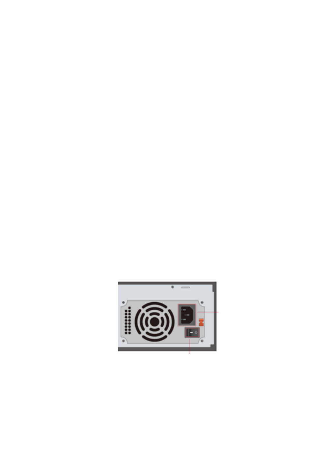
1.5 Connections
Video Output Connections
Video Output: Supports VGA/HDMI/CVBS/Spot video output (Depends on models). You can
connect to monitor through these video output interfaces simultaneously or independently.
Audio Connections
Audio Input: Connect to microphone, pickup, etc.
Audio Output: Connect to headphone, sound box or other audio output devices.
Alarm Connections
Only selected models support this function. See below 16 CH alarm inputs and 1 CH alarm
output for example.

Basic Operation Guide User Manual
13
Alarm Input (Availability depends on model):
Alarm IN 1~16 are 16CH alarm input interfaces. There are no type requirements for sensors.
NO type and NC type are both available and can be configured from the device interface .
The method to connect sensors the device is as shown below: to
The alarm input is an open/close relay. If the input is not an open/close relay, please refer to the
following connection diagram:
Alarm Output (Availability depends on model):
The way to connect alarm output device:
Pull out the green terminal blocks and loosen the screws in the alarm-out port. Then insert the
signal wires of the alarm output devices into the port of NO and COM separately. Finally,
tighten the screws. Provided that the external alarm output devices need power supply, you can
connect the power supply as per the following figures.

Basic Operation Guide User Manual
16
2.3 Mouse Control
Mouse control in Live Preview & Playback interface
In the live preview & playback interface, double click on any camera window to show the
video in single screen mode; double click the window again restore it to the previous split. to
If the interfaces display in full screen, move the mouse to the bottom or to the right side of the
interface to pop up the relevant tool bar. The tool bar will disappear automatically after you
move the mouse away from it;
Mouse control in text-input
Move the mouse to the text-input box and click the box. When required to input text the
keyboard will pop up automatically.
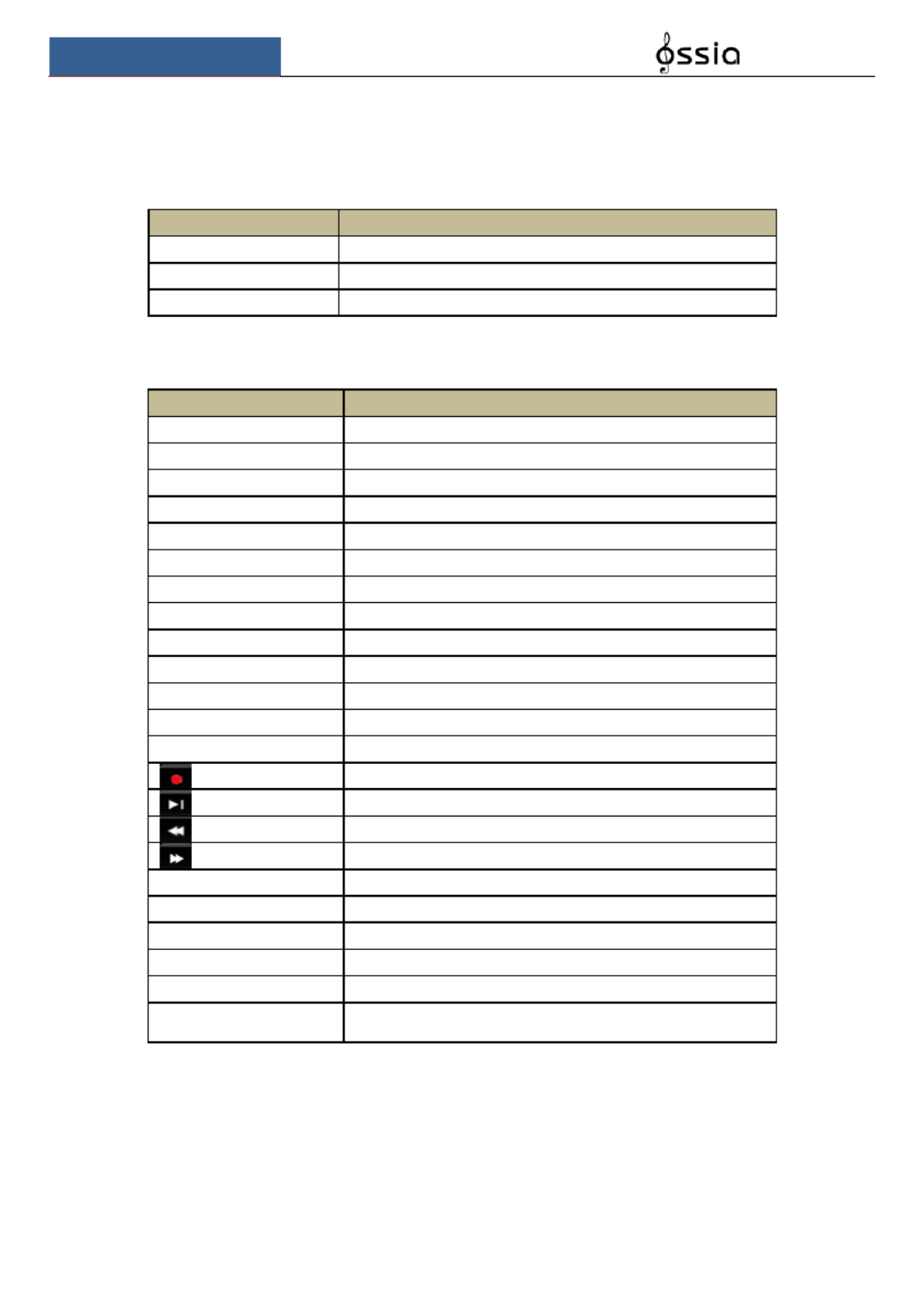
2.4 Text-i Instruction nput
The system includes two input keyboard layout as shown the above pictures. The left box is the
number input keyboard and the right box is the general input keyboard which provides inputs
of numbers, letters and punctuation characters as shown below
Button
Meaning
Button
Meaning
Backspace key
Switch punctuation characters to
Delete Key
Enter key
Switch key between upper
and lower-case letters
Space key
2.5 Other Button Operations
Button
Meaning
Show the menu list.
Change the sequence order within the list.
Change the camera display mode.
Close the current interface.
Go to the earliest date of camera recording.
Go to the latest date of camera recording.
Note: The mouse is the default controller for all operations unless mentioned otherwise.
Wizard & Main Interface User Manual
17
3 Wizard & Main Interface
3.1 Startup Wizard
On each startup, the disk icons will be shown on the top of the interface. You can view the
number and status of each disk quickly and conveniently through these icons
1) No disk
2) Unavailable disk
3) R/W available disk
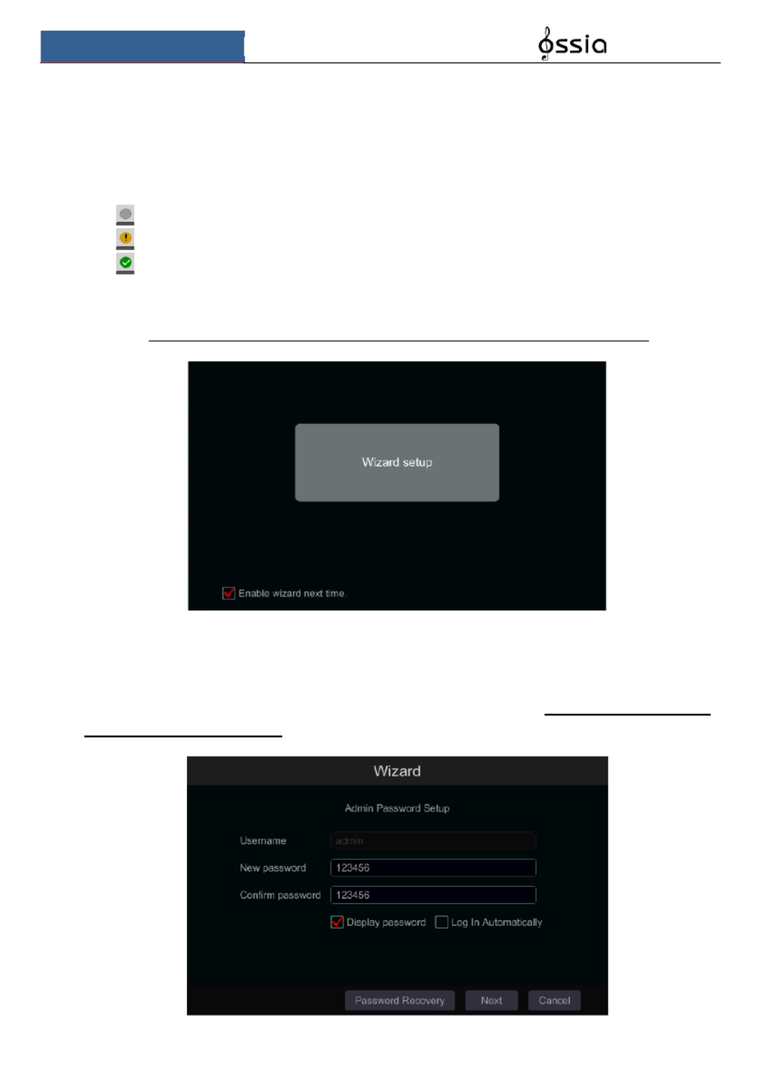
You can quickly and easily configure the device using the setup wizard. The wizard can also be
skipped and will be shown in the next startup unless the “Enable wizard next time” was
unticked. Skipping the wizard will automatically set the default password to “123456”
Click Wizard Setup to start. The setting steps are as follows: “ ”
① Admin settings. (Appears only one time on the first system startup): Set your own admin –
password or use the default when you use the wizard for the first time (the default username is
admin 123456skipping this part will set the default password to “ ”); It is highly advisable to
change the default password.
Wizard & Main Interface User Manual
19
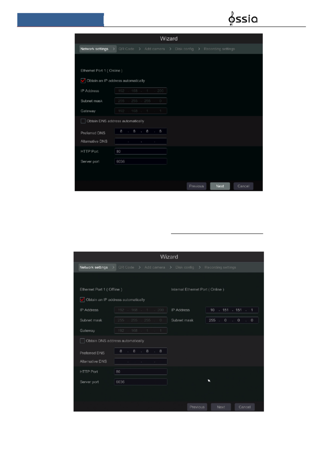
Picture reference for DVR/Non-PoE NVR
Network setting PoE NVRs – :
If you use PoE NVR, the state of the internal ethernet port will be shown on the interface as
seen on the picture below. Please refer to 11.1.1 TCP/IPv4 Configuration for detail ed
introduction of the internal ethernet port.
Picture reference for PoE NVR
Specyfikacje produktu
| Marka: | Provision ISR |
| Kategoria: | Rejestrator głosu |
| Model: | SH-4050A-4 |
Potrzebujesz pomocy?
Jeśli potrzebujesz pomocy z Provision ISR SH-4050A-4, zadaj pytanie poniżej, a inni użytkownicy Ci odpowiedzą
Instrukcje Rejestrator głosu Provision ISR

3 Października 2024
3 Października 2024
3 Października 2024
3 Października 2024
3 Października 2024
3 Października 2024
3 Października 2024
3 Października 2024
3 Października 2024
3 Października 2024
Instrukcje Rejestrator głosu
- Rejestrator głosu Sony
- Rejestrator głosu Yamaha
- Rejestrator głosu Motorola
- Rejestrator głosu Philips
- Rejestrator głosu SilverCrest
- Rejestrator głosu Hikvision
- Rejestrator głosu Roland
- Rejestrator głosu Panasonic
- Rejestrator głosu Nedis
- Rejestrator głosu Boss
- Rejestrator głosu Audioline
- Rejestrator głosu Marquant
- Rejestrator głosu Toshiba
- Rejestrator głosu D-Link
- Rejestrator głosu Majestic
- Rejestrator głosu Profoon
- Rejestrator głosu Salora
- Rejestrator głosu Grundig
- Rejestrator głosu Swann
- Rejestrator głosu Kodak
- Rejestrator głosu Digitus
- Rejestrator głosu Dahua Technology
- Rejestrator głosu DataVideo
- Rejestrator głosu Zoom
- Rejestrator głosu Marantz
- Rejestrator głosu Vivotek
- Rejestrator głosu Speco Technologies
- Rejestrator głosu Samson
- Rejestrator głosu Olympus
- Rejestrator głosu GoClever
- Rejestrator głosu AirLive
- Rejestrator głosu LevelOne
- Rejestrator głosu Axis
- Rejestrator głosu Sanyo
- Rejestrator głosu Oregon Scientific
- Rejestrator głosu Abus
- Rejestrator głosu Olympia
- Rejestrator głosu Saramonic
- Rejestrator głosu Sangean
- Rejestrator głosu AVerMedia
- Rejestrator głosu RCA
- Rejestrator głosu AJA
- Rejestrator głosu Trevi
- Rejestrator głosu Gefen
- Rejestrator głosu Hanwha
- Rejestrator głosu Lectrosonics
- Rejestrator głosu Blackmagic Design
- Rejestrator głosu Tascam
- Rejestrator głosu Lervia
- Rejestrator głosu Qian
- Rejestrator głosu Atomos
- Rejestrator głosu GPO
- Rejestrator głosu Audiovox
- Rejestrator głosu Konig
- Rejestrator głosu Mpman
- Rejestrator głosu Humax
- Rejestrator głosu Dnt
- Rejestrator głosu Irradio
- Rejestrator głosu Engel Axil
- Rejestrator głosu EverFocus
- Rejestrator głosu M-Audio
- Rejestrator głosu Livescribe
- Rejestrator głosu Griffin
- Rejestrator głosu Kguard
- Rejestrator głosu Neo
- Rejestrator głosu Epcom
- Rejestrator głosu Feelworld
- Rejestrator głosu Syscom
- Rejestrator głosu Pixel Maker
- Rejestrator głosu AVTech
- Rejestrator głosu Jammin Pro
- Rejestrator głosu Mach Power
Najnowsze instrukcje dla Rejestrator głosu

5 Kwietnia 2025

5 Kwietnia 2025
4 Marca 2025
15 Stycznia 2025
14 Stycznia 2025
30 Grudnia 2025
29 Grudnia 2024

27 Grudnia 2024
21 Grudnia 2024
15 Grudnia 2024