Instrukcja obsługi Phonic MAX 1500 Plus
Przeczytaj poniżej 📖 instrukcję obsługi w języku polskim dla Phonic MAX 1500 Plus (24 stron) w kategorii odbiornik. Ta instrukcja była pomocna dla 14 osób i została oceniona przez 2 użytkowników na średnio 4.5 gwiazdek
Strona 1/24

MAX 2500 Plus

POWER AMPLIFIER
AMPLIFICADOR POTENCIADO
MAX 1000
MAX 1500
MAX 2500
V1.0 03/16/2017
ENGLISH I ................................
ESPAÑOL ..............................II
English Español

English Español
INTRODUCTION...............................................1
FEATURES...............................................................1
GETTING STARTED...................................................1
INSTALLATION.......................................................1
CONNECTIONS........................................................2
OPERATION..............................................................3
PROTECTION...................................................................6
SPECIFICATIONS.....................................................7
CONTENTS
Phonic reserves the right to improve or alter any information within this
document without prior notice.

1. Read hese instructions operating hist before t
apparatus.
2. Keep these instructions for future reference.
3. Heed all warnings to ensure safe operation.
4. Follow all instructions provided in this document.
5. Do not use this apparatus near water r in locations o
where condensation may occur.
6. Clean only with dry cloth. Do not use aerosol or liquid
cleaners. Unplug this apparatus before cleaning.
7. Do not block any of the ventilation openings. Install
in accordance with the manufacturer
’
s instructions.
8. Do not install near any heat sources such as radiators,
heat registers, stoves, or other apparatus (including
.
9. Do not defeat the safety purpose of he polarized or t
grounding-type plug. A polarized plug has two blades
with one wider than the other. grounding type plug A
has two blades and a third grounding prong. The wide
blade or he third prong is provided for your safety. If t
the provided plug does not into your outlet, consult
an electrician for replacement of the obsolete outlet.
10. Protect the power cord from being walked on or
pinched particularly at plug, convenience receptacles,
and the point where they exit from the apparatus.
11. Only use attachments/accessories by the
manufacturer.
12. Use only with a cart, st tand, ripod, bracket, or
table by the manufacturer, or sold with
the apparatus. When a cart is used, use autioc n
when moving the cart/apparatus
combination to avoid injury from tip-
over.
13. Unplug this apparatus during lighting
storms or when unused for long
periods of time.
14. Refer all servicing to service personnel.
Servicing is required when the apparatus has been
damaged in any ay, such as power-supply cord or w
plug is damaged, liquid has been spilled or objects
have fallen into the apparatus, the apparatus has
been exposed to rain or moisture, does not operate
normally, or has been dropped.
IMPORTANT SAFETY INSTRUCTIONS
CAUTION: O REDUCE THE RISK OF ELECTRIC SHOCK, T
DO NOT REMOVE COVER (OR BACK)
NO USER SERVICEABLE PARTS INSIDE
REFER SERVICING TO QUALIFIED PERSONNEL
The lightning lash with arrowhead symbol,f within an
equilateral triangle, is intended to alert the user to the
presence of uninsulated
“
dangerous voltage
”
within the
product
’
magnitude to constitute a risk of electric shock to persons.
The exclamatio an equilatera isn point within l triangle in-
tended to alert the user to the presence of important operat-
ing and maintenance (servicing) instructions in the literature
accompanying the appliance.
WARNING: To reduce the risk of or electric shock, do
not expose this apparatus to rain or moisture.
CAUTION: Use of controls or adjustments or performance
of procedures other than those may result in
hazardous radiation exposure.
The apparatus shall not be exposed to dripping or splashing and that no objects with liquids, such as vases,
shall be placed on the apparatus. The MAINS plug is used as the disconnect device, the disconnect device shall
remain readily operable.
Warning: the user shall not place this apparatus in the area during the operation o that the mains switch s
can be easily accessible.
CAUTION
RISK OF ELECTRIC SHOCK
DO NOT OPEN
English

1MAX 1000 MAX 1500 | | 2500
English
INTRODUCTION
Thank you for purchasing a MAX series power am-
plier. Based on years of experience in designing
and manufacturing professional audio equipment,
we at Phonic designed this power amplier for those
who need an extremely powerful, reliable and sturdy
amplier with a small footprint. Taking advantage of
its huge heat sink as well as its variable speed fan
that auto-adjusts fan speed depending on the tem-
perature of the machine during operation, MAX power
amps are always able to perform. Its professional
quality output and its sturdy case design make this
unit great for various locations like churches, concert
tours, stages, disco, pubs, or any place that requires
amplier installation.
This unit is designed with great care and great atten-
tion to details, so please read this manual carefully.
Look after it and keep it in a safe place for future
reference.
FEATURES
● Up to 1500 Watts with only 2U footprint
● Output: 300W for MAX 1000, 450W for MAX 1500
Plus and 750W for MAX 2500 Plus, all at 4 ohms
● High current toroidal transformer allowing high
power output with low noise and low distortion
● Built in limiter with a button allowing user to dis-
able limiter
’
s function
● Balanced 1/4” TRS and XLR inputs for maximum
exibility
● Grounding / Floating switch to avoid grounding
loop
● Binding post and speakon outputs
● Front mounted gain controls for easy access
● Signal and Peak LED indicators to monitor per-
formance
● Protection: short circuit, thermal, subsonic, RF
protection, output DC oset, power on/o muting
GETTING STARTED
● Check the AC voltage before connecting the power
plug to the outlet. Make sure the AC power supply
shares the same voltage used in your country (For
example, while some countries use 100V, others
use 120V, 230V, or 240V). Please ensure your
device is properly grounded.
● Before turning on the power, make sure the gain
controls are turned all the way down to prevent
other equipment from harm.
● Check your cables regularly and label each end
clearly for easy identication.
● Always turn the power o before connecting to
and disconnecting from the unit.
● NEVER use solvents to clean the unit. Clean it
with a soft and damp or dry cloth.
INSTALLATION
MOUNTING THE UNIT
Designed to t into a standard 19-inch rack, this unit
only takes up 2 units of rack space. Secure this unit
with 4 rack-mount screws and cup washers. In gen-
eral, power ampliers usually are heavier than any
other audio equipment, so when installing this unit
onto a rack, begin placing it from the bottom of the
rack. Leave 1-rack space between power ampliers
and other devices to guarantee better cooling (see
Figure 1).

3MAX 1000 MAX 1500 | | 2500
English
OPERATION
FRONT PANEL
4. POWER SWITCH
This switch turns the power of the unit on. Remember to
turn the gain controls down before turning power on or o,
even though it comes with a POWER ON / OFF MUTING
feature. In general, the power amplier should be the last
piece of audio equipment to be powered on, and the rst
to be powered o, in a PA system.
5. POWER LED
This blue LED comes on when power is on.
6. PEAK LED
When the input signal level becomes too high, causing input
signal to loss denition and to distort, this red LED comes
on. When this happens, turn the gain control down until the
PEAK LED no longer comes on or remains on continously.
7. SIGNAL LED
Every channel comes with a signal LED, allowing user to
monitor signal level. A minimum level of -30dBu is required
for the LED to go on.
8. GAIN CONTROLS
These two rotary knobs control the signal level of the input.
Center detented control allows precise volume setting.
Slowly turn the knob clockwise to increase input level, but
make sure that PEAK LED does not remain on or blink
constantly.
REAR PANEL
9. Grounding/Floating Switch
This switch allows the circuit and chassis grounds to be
separated in case of a ground conict. In normal use the
switch should be in the Ground On position. Lifting the
ground (Floating position) may resolve the ground con-
ict, but means that circuit grounding will depend on other
connected components. Deciencies in other components’
grounding will aect the sound and a serious electric fault
with the amplier could damage other components in the
system.
10. PARALLEL / STEREO / BRIDGE MONO
OPERATING MODE
There are three operation modes for dierent use. To avoid
damaging your PA system, remember to turn the power o
before switching from one mode to the other.
876 5
4
10
9

4MAX 1000 MAX 1500 | | 2500
English
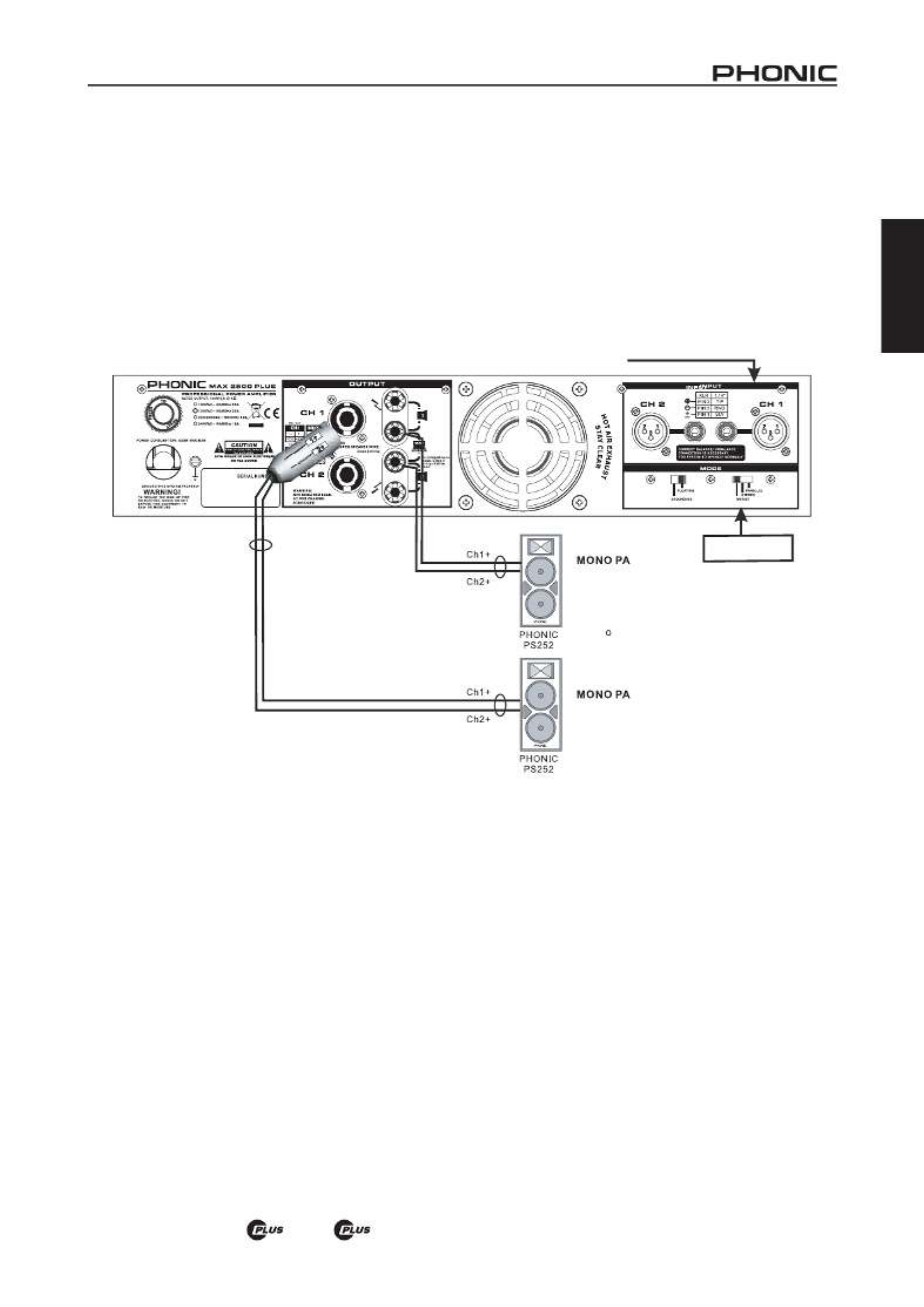
PARALLEL
When set to PARALLEL mode, the input signal of Channel 2 parallels the input signal of Channel 1, so only one input jack
is needed for the signal source. Even though the input signal of both channels parallels each other, the output level of each
channel is determined by its own independent gain controls. So the two channels sharing the same signal do not share
the same output level (see Figure 4).
STEREO
STEREO mode is the most frequently used mode among the three. Each channel is independent of the other, carrying its
own input signal, with its own gain control. Stereo mode comes in left and right channels (See Figure 5).
A) When one channel is assigned for left channel, make sure the other channel is assigned for the right.
B) User can use the unit for mono output, with one as main and the other as monitor.
C) This power amplier can also be used for bi-amplication. One channel for driving low frequencies while the other for
driving high frequencies.
(or HF)
(or LF)
Set Amp Mode
to Stereo
F Eigure 5 STEREO MOD

5MAX 1000 MAX 1500 | | 2500
English
BRIDGE MONO
This mode is for those who need high level output. It combines the power of both channels to produce the maximum amount
of power the unit can handle. Make sure your speaker can handle higher wattage this mode oers. Remember, the minimum
impedance requirement is 4 ohm. When bridge mono, make sure only Channel 1 input is in use. When using speakon,
treat PIN 1+ as the
“
+
”
and PIN 2+ as the
“
-
”
; when using binding posts, treat Channel 1 + as the
“
+
”
and Channel 2 + as
the
“
-
”
. Do not use Channel 2
’
s speakon output in this mode. When bridge mono, the gain control of Channel 1 controls
the total level output (See Figure 6).
WARNING: Bridge mono operation produces higher current output than the other two operations, thus make
sure the gain is set at the proper level and speakers being used can handle the wattage amplier produce.
Proper attention to wiring is greatly needed to prevent experiencing electric shock.

6MAX 1000 MAX 1500 | | 2500
English
10. CHASSIS GROUNDING CONNECTING POINT
To avoid the possibility of ground loop, this unit comes with
chassis grounding point allowing it to be connected to other
units for sharing a common grounding.
11. POWER CORD
This cord draws electricity from power outlet. Near by it,
there is an indicator that tells you what voltage your unit
operates in. Check the AC voltage before connecting the
power plug to the outlet. Make sure the AC requirement
shares the same voltage used in your country (For example,
while some countries use between 110V and 120V, others
use 230V to 240V).
12. RESET SWITCH
Push this button to reset the unit in the unlikely event that
it locks up.
PROTECTION
The unit comes with many circuitry protection features for
preventing it and speakers it’s connected to from harm.
SHORT CIRCUIT: When speakers short circuit, this fea-
ture protects the amplier by cutting o the output current
to the speakers.
THERMAL: Heat is created during high level output
–
es-
pecially when during bridge operation. The unit comes with
variable speed fan that auto-adjusts speed depending on
the temperature of the machine during operation. Howev-
er, for some reason the unit could not eectively vent out
excessive heat, this feature would protect the unit from
over-heating by shutting its power o.
OUTPUT DC OFFSET: When direct current enters to the
connection between the power amplier and speakers, it
hurts the speakers by causing drivers and cones to work
under stress. This feature prevents this from happening
by cutting o the output current to the speakers when such
situation happens.
POWER ON / OFF MUTING: There is a two to three
second delay before the unit sends out any signal. During
this 2 - 3 seconds, the system will be on mute, no signal
exist this unit.
SUBSONIC: Frequencies below 10Hz contain high level of
energy that can be harmful and stressful for many speakers.
Since normal human listening range from 20Hz to 20KHz,
this unit comes with a feature that helps lter out any fre-
quency that is below 10Hz to prevent speakers from harm.
RF PROTECTION: Radio Frequency is everywhere. This
feature prevents radio frequency interference by ltering out
frequency signal that
’
s above 200KHz. This help prevent
radio program signals from entering this unit.
12
11
10

7MAX 1000 MAX 1500 | | 2500
English
All specications are subject to change without notice.
SPECIFICATIONS
MAX 1000 MAX 1500 Plus MAX 2500 Plus
Stereo Mode (driving both channels) Continuous Average Output Power Per Channel
8Ω EIA 1kHz 0.1%THD 200W 280W 500W
4Ω EIA 1kHz 0.1%THD 300W 450W 750W
Bridge Mono Mode Continuous Average Output Power
8Ω EIA 1kHz 0.1%THD 900W600W 1500W
All Models
Output Circuitry Class AB Class H
Input Aensitivity @ 8Ω 1.23V (+4dBu)
Distortion (SMPTE-IM) <0.01% <0.02%
Noise (unweighted 20Hz-20KHz below
rated output) 100dB
Damping Factor >300 @ 8Ω
Frequency Response 20 Hz-20KHz, +0/-1dB; -3dB points: 5Hz-50KHz
Input Impedance 20 K Ω balanced, 10 K Ω unbalanced
Cooling Continuous variable-speed fan, front-to-rear air ow
Connectors (each channel) Input: XLR and 1/4” TRS; Output: Speakon and binding posts
Indicators Power: Blue LED; SIGNAL: Green LED; PEAK: Red LED
Controls
Front Panel CH1 & CH2 GAIN knobs with 21 detents
Rear Panel Slide switches: Operation mode: Parallel, Bridge, Stereo;
Grounding/Floating; Current-Break reset button
Protection Circuitry Short circuit, thermal, subsonic, RF protection,
Output DC oset, Power on/o muting
Power Consumption 600W 1500W900W
Power Requirement (depends on region) 100~120VAC, 220~240VAC, 50/60Hz
Dimensions (WxHxD) 482 x 88 x 415mm (19” x 3.46” x 15.9”)
Weight 10.16 kg (22.4 lbs) 11.15 kg (24.6 lbs) 13.24 kg (29.2 lbs)

English
SERVICE AND REPAIR
For replacement parts, service and repairs please contact the Phonic distributor in your
countr honic does not release service manuals to consumers, and advice users to not y. P
attempt any self repairs, as doing so voids all warranties. u can locate a dealer near you atYo
http://www.phonic.com/where-to-buy/.
WARRANTY INFORMATION
Phonic stands behind every product we make with a no-hassles warranty. rranty coverage Wa
may be extended, depending on your region. honic Corporation warrants this product for a P
minimum of one year from the original date of purchase against defects in material and
workmanship under use as instructed by the user manual. Phonic, at its option, shall repair ’s
or replace the defective unit covered by this warrant Please retain the dated sales receipt asy.
evidence of the date of purchase. You will need it for any warranty service. No returns or repairs
will be accepted without a proper RM number (return merchandise authorization). In order toA
keep this warranty in effect, the product must have been handled and used as prescribed in the
instructions accompanying this warranty. Any tampering of the product or attempts of self repair
voids all warrant This warranty does not cover any damage due to accident, misuse, abuse,y.
or negligence. This warranty is valid only if the product was purchased new from an authorized
Phonic dealer/distributo For complete warranty policy information, please visit r.
http://www.phonic.com/warranty/.
CUSTOMER SERVICE AND TECHNICAL SUPPORT
We encourage you to visit our online help at http://support.phonic.com/. There you can find
answers to frequently asked questions, tech tips, driver downloads, returns instruction and other
helpful information.
FCC Caution: ssure continued compliance, any changes or modifications not expressly To a
approved by the party responsible for compliance could void the user's authority to operate this
equipment. (Example - use only shielded interface cables when connecting to computer or
peripheral devices).
THIS DEVICE COMPLIES WITH 74 OF THE FCC RULES. This equipment complies with PART
FCC RF radiation exposure limits set forth for an uncontrolled environment.
support@phonic.com
http://www.phonic.com

English
CONTENIDO
INTRODUCCIÓN.........................................................1
CARACTERÍSTICAS.............................................................1
INICIANDO......................................................................1
INSTALACIÓN.........................................................................1
CONEXIONES......................................................................2
OPERACIÓN......................................................................3
PROTECCIÓN.................................................................6
ESPECIFICACIONES...........................................................7
Phonic se reserva el derecho de mejorar o alterar cualquier información
provista dentro de este documento sin previo aviso.

Español

2MAX 1000 MAX 1500 | | 2500
Español
1. VENTILACIÓN DE CALOR
Esta unidad viene con ventilador de velocidad
variable que auto-ajusta la velocidad del ventilador
dependiendo de la temperatura de la máquina
durante la operación. Asegúrese de no obstruir
los agujeros de ventilación del calor de ninguna
manera. Esto asegurará a que el amplificador
siempre esté ventilado correctamente.
CONEXIONES
2. ENTRADA
Conecte su fuente a jack XLR o 1/4” TRS, que
son comunmente usado para configuraciones
m ó v i l e i n s t a l a c i ó n . P r o v e e n u n a b u e na
combinación de fácil conexión y resistencia
a cor ros ión. Las ent radas XLR deben ser
cableados como se muestran en figura 2.
3. SALIDA
Los conectadores de binding posts y speakon
componen la sección de salida de la unidad.
Los altavoces pueden ser fácilmente conectados
usando los enchufes banana, spade lugs, cables
pelados o conectador speakon. Más gente preere
usar speakon que otros conectadores porque es
el que menos probable de ser desconectado por
accidente o causar choque eléctrico. Porque el
speakon viene con cuatro alambres adentro, usted
puede conectar a dos altavoces con una sola salida
del canal. Tenga cuidado al hacer las conexiones
ya que la conexión incorrecta podría causar
cortocircuitos a la unidad. El ajuste de impedancia
mínima para la operación ESTÉREA y PARALELA
es de 4 ohmios, mientras que 8 ohmios es el ajuste
mínimo para BRIDGE MONO (ver Figura 3).
3 1 2
Figura 2 Cableado de Entrada
Speakon Output
Binding Po t Output
Figura 3 Cableado de Salida

4MAX 1000 MAX 1500 | | 2500
Español
PARALELO
Cuando se setea a modo PARALELO, la señal de entrada del Canal 2 es paralela a la señal de entrada del
Canal 1, por lo tanto se necesita solo un jack de entrada para la fuente de señal. Aunque la señal de entrada
de ambos canales es paralela una de otra, el nivel de salida de cada canal es determinado por sus propios
controles independientes de ganancia. Por lo tanto, los dos canales que comparten la misma señal no
comparten el mismo nivel de salida (ver Figura 4).
ESTÉREO
El modo ESTÉREO es el modo usado más frecuentemente entre los tres. Cada canal es independiente uno de
otro, llevando su propia señal de entrada, con su propio control de ganancia. El modo estéreo viene en canales
izquierdos y derechos (Ver Figura 5).
A) Cuando un canal es asignado para el canal izquierdo, cerciórese de que el otro canal esté asignado para el
derecho.
B) El usuario puede utilizar la unidad para la salida mono, con uno como principal y el otro como monitor.
C) Este amplificador de potencia puede ser utilizado también para bi-amplificación. Un canal para conducir
frecuencias bajas mientras que el otro para conducir frecuencias altas.
Setea el Modo de
Amp a Paralelo
Entrada Mono
Figura 4 MODO PARALELO
Figura 5 MODO ESTÉREO
lzquierdo(o CH1, o HF)
Derecho(o CH2, o LF)
lzquierdo(o HF)
Derecho(o LF)
Setea el Modo de
Amp a Estéreo
5MAX 1000 MAX 1500 | | 2500
English
BRIDGE MONO
Este modo es para los que necesitan salida de nivel alto. Combina la energía de ambos canales para producir
la cantidad máxima de energía que la unidad puede manejar. Asegúrese de que su altavoz pueda manejar un
vatiaje más alto que este modo ofrece. Recuerde, el requisito mínimo de la impedancia es de 4 ohmios. En
bridge mono, asegúrese que solamente la entrada de Canal 1 está en uso. Cuando se usa el speakon, trate a
PIN 1+ como “+” y PIN 2+ como “-”; cuando se usa binding posts, trate al Canal 1 + como “+” y Canal 2 + como
“-”. No utilice la salida de speakon del Canal 2 en este modo. En bridge mono, el control de ganancia del Canal
1 controla la salida de nivel total (Ver Figura 6).
ADVERTENCIA: La operación bridge mono produce salida de corriente más alta que las otras dos
operaciones, así asegúrese de que la ganancia esté seteada en el nivel apropiado y los altavoces utilizados
pueden manejar el vatiaje que el amplicador produce. Se necesita de gran atención apropiada al cableado
para evitar la descarga eléctrica.
Figura 6 MODO BRIDGE MONO
Entrada Mono
(o subwoofer)
(o subwoofer)
Setea el Modo de
Amp a Bridge Mono

6MAX 1000 MAX 1500 | | 2500
Español
10. PUNTO DE CONEXIÓN DE CHASSIS A
TIERRA
Para evitar la posibilidad del lazo de tierra, esta
unidad viene con el punto de chassis a tierra
permitiendolo que sea conectado a otras unidades
para compartir la conexión a tierra común.
11. CABLE DE ENERGÍA
Este cable conduce electricidad desde la salida
de energía. Cerca de él, hay un indicador que le
dice a qué voltaje funciona su unidad. Chequee el
voltaje AC antes de conectar el enchufe de energía
a la salida. Cerciórese de que el requisito de AC
comparte el mismo voltaje usado en su país (Por
ejemplo, mientras que algunos países usan entre
110V y 120V, otros utilizan 230V a 240V).
12. INTERRUPTOR DE RESET
Pulse este botón para resetear la unidad en el
acontecimiento inverosímil en el que se traba.
PROTECCIONES
La unidad viene con muchas características de
protección de circuito para prevenir la unidad y los
altavoces conectados del daño.
CORTOCIRCUITO: Cuando los altavoces se ponen
en cortocircuitos, esta característica protege el
amplificador cortando la corriente de salida a los
altavoces.
TERMAL: El calor se crea durante la salida de
alto nivel - especialmente durante la operación de
bridge. La unidad viene con ventilador de velocidad
variable que auto-ajusta la velocidad dependiendo
de la temperatura de la máquina durante la
operación. Sin embargo, por alguna razón la unidad
no podía sacar con ecacia el calor excesivo, esta
característica protegería la unidad contra el sobre-
calentamiento apagando su energía.
OFFSET DE SALIDA DC: Cuando la corriente
directa entra a la conexión entre el amplicador de
potencia y los altavoces, lastima a los altavoces
causando los controladores y conos funcionar bajo
tensión. Esta característica evita que ésto suceda
cortando la corriente de salida a los altavoces
cuando ocurre tal situación.
ENMUDECIMIENTO DE ENCENDIDO / APAGADO
DE ENERGÍA: Hay dos a tres segundos de retardo
antes de que la unidad envíe cualquier señal.
Durante estos 2-3 segundos, el sistema estará en
mudo, no existe señal en esta unidad.
SUBSÓNICO: Las frecuencias debajo de 10Hz
contienen alto nivel de energía que pueden ser
dañosas y agotadoras para muchos altavoces.
Como el rango de la escucha humana normal
es de 20Hz a 20KHz, esta unidad viene con una
característica que ayuda a ltrar cualquier frecuencia
que está debajo de 10Hz para evitar que se dañen
los altavoces.
PROTECCIÓN RF: La Radiofrecuencia está
por todas partes. Esta característica previene
interferencia de la radiofrecuencia ltrando la señal
de la frecuencia que está sobre 200KHz. Esto ayuda
a prevenir que las señales del programa de radio
entran a esta unidad.
12
11
10
Specyfikacje produktu
| Marka: | Phonic |
| Kategoria: | odbiornik |
| Model: | MAX 1500 Plus |
Potrzebujesz pomocy?
Jeśli potrzebujesz pomocy z Phonic MAX 1500 Plus, zadaj pytanie poniżej, a inni użytkownicy Ci odpowiedzą
Instrukcje odbiornik Phonic

12 Grudnia 2024
12 Grudnia 2024
12 Grudnia 2024
12 Grudnia 2024
12 Grudnia 2024
12 Grudnia 2024
12 Grudnia 2024
12 Grudnia 2024
12 Grudnia 2024
12 Grudnia 2024
Instrukcje odbiornik
- odbiornik Sony
- odbiornik Yamaha
- odbiornik Motorola
- odbiornik Logitech
- odbiornik Sharp
- odbiornik Pioneer
- odbiornik Philips
- odbiornik Plantronics
- odbiornik SilverCrest
- odbiornik Technics
- odbiornik Bosch
- odbiornik JBL
- odbiornik Onkyo
- odbiornik Edision
- odbiornik Roland
- odbiornik Geemarc
- odbiornik Nokia
- odbiornik KEF
- odbiornik Bose
- odbiornik Zgemma
- odbiornik Panasonic
- odbiornik StarTech.com
- odbiornik Klipsch
- odbiornik Crestron
- odbiornik Behringer
- odbiornik Asus
- odbiornik Nedis
- odbiornik Nexa
- odbiornik Medion
- odbiornik Tangent
- odbiornik Boss
- odbiornik Peiying
- odbiornik Marquant
- odbiornik Majestic
- odbiornik Jensen
- odbiornik August
- odbiornik Garmin
- odbiornik Blaupunkt
- odbiornik ATen
- odbiornik Salora
- odbiornik Teac
- odbiornik Metra
- odbiornik Martin Logan
- odbiornik Dual
- odbiornik Hegel
- odbiornik S.M.S.L
- odbiornik Line 6
- odbiornik DAP-Audio
- odbiornik Manhattan
- odbiornik Strong
- odbiornik Tripp Lite
- odbiornik Shure
- odbiornik Denon
- odbiornik Mercury
- odbiornik Block
- odbiornik Phoenix Gold
- odbiornik Audac
- odbiornik Cisco
- odbiornik Cambridge
- odbiornik Smart
- odbiornik Kenwood
- odbiornik Scosche
- odbiornik NuPrime
- odbiornik Polk
- odbiornik DJI
- odbiornik Alpine
- odbiornik Ibanez
- odbiornik Godox
- odbiornik Chamberlain
- odbiornik Lindy
- odbiornik Bang & Olufsen
- odbiornik JVC
- odbiornik Konig & Meyer
- odbiornik Trust
- odbiornik LogiLink
- odbiornik Memphis Audio
- odbiornik IFM
- odbiornik Datapath
- odbiornik Jamo
- odbiornik Focusrite
- odbiornik Rega
- odbiornik IRiver
- odbiornik Hilti
- odbiornik TechniSat
- odbiornik Auna
- odbiornik Vimar
- odbiornik Nubert
- odbiornik Dahua Technology
- odbiornik LD Systems
- odbiornik Krüger&Matz
- odbiornik Audioengine
- odbiornik Emos
- odbiornik AVMATRIX
- odbiornik Renkforce
- odbiornik Marshall
- odbiornik Audiotec Fischer
- odbiornik Clarion
- odbiornik Thomson
- odbiornik DiO
- odbiornik Pro-Ject
- odbiornik AVM
- odbiornik Velleman
- odbiornik Ferguson
- odbiornik Fusion
- odbiornik BOYA
- odbiornik Homematic IP
- odbiornik Neumann
- odbiornik DataVideo
- odbiornik Wharfedale
- odbiornik Intertechno
- odbiornik Magnat
- odbiornik Delta Dore
- odbiornik Pyle
- odbiornik ELAC
- odbiornik Zoom
- odbiornik Panduit
- odbiornik Devolo
- odbiornik Marantz
- odbiornik Sennheiser
- odbiornik Esoteric
- odbiornik Jabra
- odbiornik Chord
- odbiornik Vivotek
- odbiornik Speco Technologies
- odbiornik Medeli
- odbiornik Bowers & Wilkins
- odbiornik Samson
- odbiornik Imperial
- odbiornik PreSonus
- odbiornik Monitor Audio
- odbiornik Audio Pro
- odbiornik Blackstar
- odbiornik Fosi Audio
- odbiornik Revox
- odbiornik Ibiza Sound
- odbiornik Vonyx
- odbiornik Musical Fidelity
- odbiornik Bogen
- odbiornik Alto
- odbiornik Naim
- odbiornik Peavey
- odbiornik Camille Bauer
- odbiornik ART
- odbiornik NAD
- odbiornik RCF
- odbiornik Harman Kardon
- odbiornik Rolls
- odbiornik Audio-Technica
- odbiornik GoGen
- odbiornik Genie
- odbiornik Blustream
- odbiornik Aiwa
- odbiornik JL Audio
- odbiornik AKAI
- odbiornik Axis
- odbiornik ICOM
- odbiornik Vivolink
- odbiornik REL Acoustics
- odbiornik Teufel
- odbiornik Sunfire
- odbiornik Hartke
- odbiornik Klark Teknik
- odbiornik Vision
- odbiornik Telefunken
- odbiornik Eventide
- odbiornik Optoma
- odbiornik Proel
- odbiornik Hifonics
- odbiornik Focal
- odbiornik Taga Harmony
- odbiornik Audix
- odbiornik DBX
- odbiornik Kicker
- odbiornik Amazon
- odbiornik Thorens
- odbiornik Bresser
- odbiornik Rocstor
- odbiornik Omnitronic
- odbiornik Hama
- odbiornik Mackie
- odbiornik Marmitek
- odbiornik Palmer
- odbiornik FiiO
- odbiornik Lindell Audio
- odbiornik Vincent
- odbiornik Smart-AVI
- odbiornik MXL
- odbiornik Goobay
- odbiornik Optex
- odbiornik Reely
- odbiornik BC Acoustique
- odbiornik Lotronic
- odbiornik Bush
- odbiornik Dreambox
- odbiornik Saramonic
- odbiornik Bluesound
- odbiornik Kemo
- odbiornik Deaf Bonce
- odbiornik Sangean
- odbiornik VOX
- odbiornik Insignia
- odbiornik SVS
- odbiornik Hager
- odbiornik Inateck
- odbiornik Arcam
- odbiornik Mac Audio
- odbiornik Infinity
- odbiornik McIntosh
- odbiornik Advance Acoustic
- odbiornik Revel
- odbiornik Denver
- odbiornik ACV
- odbiornik Dynacord
- odbiornik Marshall Electronics
- odbiornik Ashly
- odbiornik Fender
- odbiornik Hertz
- odbiornik InLine
- odbiornik Inter-M
- odbiornik Kali Audio
- odbiornik Mooer
- odbiornik AKG
- odbiornik MEE Audio
- odbiornik Atlas Sound
- odbiornik The T.amp
- odbiornik IOTAVX
- odbiornik Futaba
- odbiornik Trevi
- odbiornik Atlona
- odbiornik Elektrobock
- odbiornik FSR
- odbiornik Simrad
- odbiornik Salus
- odbiornik Gefen
- odbiornik Vivanco
- odbiornik Fishman
- odbiornik Radial Engineering
- odbiornik Lectrosonics
- odbiornik Sencor
- odbiornik Definitive Technology
- odbiornik Ground Zero
- odbiornik Polsen
- odbiornik Raymarine
- odbiornik Stinger
- odbiornik Power Dynamics
- odbiornik AEA
- odbiornik Kanto
- odbiornik Alecto
- odbiornik Kathrein
- odbiornik Rockford Fosgate
- odbiornik Clare Controls
- odbiornik Canton
- odbiornik JUNG
- odbiornik TOA
- odbiornik Monacor
- odbiornik HQ Power
- odbiornik Hotone
- odbiornik Electro-Voice
- odbiornik Anthem
- odbiornik Audizio
- odbiornik Tascam
- odbiornik RME
- odbiornik AudioControl
- odbiornik Karma
- odbiornik Smartwares
- odbiornik Audiolab
- odbiornik Vocopro
- odbiornik Technical Pro
- odbiornik SPL
- odbiornik Fontastic
- odbiornik Cyrus
- odbiornik Gold Note
- odbiornik Terratec
- odbiornik Crunch
- odbiornik Alfatron
- odbiornik Sound Devices
- odbiornik Match
- odbiornik Megasat
- odbiornik Sogo
- odbiornik Classé
- odbiornik Reloop
- odbiornik Fenton
- odbiornik Artsound
- odbiornik Chandler
- odbiornik Belkin
- odbiornik Kramer
- odbiornik KanexPro
- odbiornik Kopul
- odbiornik BZBGear
- odbiornik Cranborne Audio
- odbiornik Rupert Neve Designs
- odbiornik Key Digital
- odbiornik Ram Audio
- odbiornik Whirlwind
- odbiornik Music Hall
- odbiornik Apantac
- odbiornik AMX
- odbiornik Inovonics
- odbiornik SRS
- odbiornik Sonance
- odbiornik Rotel
- odbiornik Atlas
- odbiornik C2G
- odbiornik Brondi
- odbiornik Lumantek
- odbiornik Ampeg
- odbiornik Amplicom
- odbiornik American Audio
- odbiornik Devialet
- odbiornik IFi Audio
- odbiornik Cabasse
- odbiornik Amiko
- odbiornik Hirschmann
- odbiornik Audison
- odbiornik Palsonic
- odbiornik Caliber
- odbiornik Meliconi
- odbiornik Exibel
- odbiornik Telestar
- odbiornik Sagem
- odbiornik Summit Audio
- odbiornik Musway
- odbiornik Brigmton
- odbiornik Sunstech
- odbiornik Avalon
- odbiornik Oculus VR
- odbiornik Redline
- odbiornik Matrox
- odbiornik Steren
- odbiornik Sandberg
- odbiornik Galaxy Audio
- odbiornik Denson
- odbiornik Renegade
- odbiornik Yaesu
- odbiornik Pyle Pro
- odbiornik Roksan
- odbiornik MB Quart
- odbiornik Valcom
- odbiornik Astro
- odbiornik Maxview
- odbiornik Rocketfish
- odbiornik Naxa
- odbiornik Sherwood
- odbiornik QTX
- odbiornik Konig
- odbiornik Valueline
- odbiornik Conrad
- odbiornik RDL
- odbiornik Zehnder
- odbiornik Mx Onda
- odbiornik Fredenstein
- odbiornik Metronic
- odbiornik Harper
- odbiornik TV STAR
- odbiornik QSC
- odbiornik Lanzar
- odbiornik Humax
- odbiornik Vaddio
- odbiornik Gira
- odbiornik Golden Age Project
- odbiornik Apart
- odbiornik Pinnacle
- odbiornik HQ
- odbiornik Max
- odbiornik Homecast
- odbiornik Graupner
- odbiornik Integra
- odbiornik Russound
- odbiornik Engel Axil
- odbiornik Comica
- odbiornik Audient
- odbiornik PAC
- odbiornik Skytec
- odbiornik Luxman
- odbiornik JETI
- odbiornik Linn
- odbiornik Monoprice
- odbiornik Yorkville
- odbiornik Advance
- odbiornik WyreStorm
- odbiornik Sonifex
- odbiornik TV One
- odbiornik Exposure
- odbiornik Axton
- odbiornik Fostex
- odbiornik FBT
- odbiornik MIPRO
- odbiornik Solid State Logic
- odbiornik Neets
- odbiornik NAV-TV
- odbiornik HiFi ROSE
- odbiornik OSD Audio
- odbiornik Mark Levinson
- odbiornik Black Lion Audio
- odbiornik Soundstream
- odbiornik Xoro
- odbiornik DLS
- odbiornik Adastra
- odbiornik PSB
- odbiornik Aeon Labs
- odbiornik Citronic
- odbiornik CSL
- odbiornik Formuler
- odbiornik Universal Audio
- odbiornik Warm Audio
- odbiornik LTC
- odbiornik JB Systems
- odbiornik Zalman
- odbiornik Orava
- odbiornik Thomann
- odbiornik James
- odbiornik HUMANTECHNIK
- odbiornik SIIG
- odbiornik PSSO
- odbiornik Crest Audio
- odbiornik Grace Design
- odbiornik Primare
- odbiornik Xantech
- odbiornik Wet Sounds
- odbiornik Televés
- odbiornik Hughes & Kettner
- odbiornik Manley
- odbiornik Intelix
- odbiornik MuxLab
- odbiornik Extron
- odbiornik Ocean Matrix
- odbiornik Comprehensive
- odbiornik HEOS
- odbiornik Legamaster
- odbiornik Madison
- odbiornik Ebode
- odbiornik Phonocar
- odbiornik Xtrend
- odbiornik Scansonic
- odbiornik Helix
- odbiornik Winegard
- odbiornik Laney
- odbiornik ETON
- odbiornik Xsarius
- odbiornik EA
- odbiornik DirecTV
- odbiornik Octagon
- odbiornik GOgroove
- odbiornik Crown
- odbiornik Kogan
- odbiornik Morel
- odbiornik Avantree
- odbiornik LYYT
- odbiornik Antelope Audio
- odbiornik CE Labs
- odbiornik Pharos
- odbiornik Accell
- odbiornik Jolida
- odbiornik Ecler
- odbiornik Lab Gruppen
- odbiornik Viscount
- odbiornik Ashdown Engineering
- odbiornik Triax
- odbiornik Synq
- odbiornik Mtx Audio
- odbiornik Aquatic AV
- odbiornik Parasound
- odbiornik DB Technologies
- odbiornik Roswell
- odbiornik Velodyne
- odbiornik Epcom
- odbiornik Selfsat
- odbiornik AVPro Edge
- odbiornik Evolution
- odbiornik Skytronic
- odbiornik CYP
- odbiornik Topp Pro
- odbiornik Whistler
- odbiornik Astell&Kern
- odbiornik Bellari
- odbiornik Dimavery
- odbiornik AMS Neve
- odbiornik A-NeuVideo
- odbiornik Aguilar
- odbiornik Powersoft
- odbiornik LinksPoint
- odbiornik Markbass
- odbiornik IMG Stage Line
- odbiornik Wireless Solution
- odbiornik Leviton
- odbiornik Aurel
- odbiornik ESX
- odbiornik NUVO
- odbiornik Phoenix Audio
- odbiornik Comtek
- odbiornik RetroSound
- odbiornik Pyramid
- odbiornik LEA
- odbiornik Sound Ordnance
- odbiornik Canyon
- odbiornik FiveO
- odbiornik Planet Audio
- odbiornik SureCall
- odbiornik CAD Audio
- odbiornik Black Hydra
- odbiornik Elipson
- odbiornik Koda
- odbiornik Trace Elliot
- odbiornik Bang Olufsen
- odbiornik JTS
- odbiornik AER
- odbiornik Dynavox
- odbiornik Modelcraft
- odbiornik Simaudio
- odbiornik TIC
- odbiornik Niles
- odbiornik Knoll
- odbiornik Creek
- odbiornik Mobile Crossing
- odbiornik DAP
- odbiornik Krell
- odbiornik Edwards Signaling
- odbiornik GigaBlue
- odbiornik ANKARO
- odbiornik Bugera
- odbiornik Triangle
- odbiornik Wavtech
- odbiornik AmpliVox
- odbiornik Audiofrog
- odbiornik CyberData Systems
- odbiornik Williams Sound
- odbiornik Lyngdorf
- odbiornik SoundTube
- odbiornik WesAudio
- odbiornik AudioSource
- odbiornik Stewart
- odbiornik Leema
- odbiornik Axing
- odbiornik Seco-Larm
- odbiornik Mosconi
- odbiornik Crest
- odbiornik TechLogix Networx
- odbiornik Audibax
- odbiornik Meridian
- odbiornik Quad
- odbiornik Shinybow
- odbiornik Rexing
- odbiornik Shanling
- odbiornik Sinus Live
- odbiornik Soundtrack
- odbiornik Canor
- odbiornik Unison Research
- odbiornik Cerwin-Vega
- odbiornik Universal Remote Control
- odbiornik BMB
- odbiornik Cloud
- odbiornik Antelope
- odbiornik PTN-electronics
- odbiornik Loxjie
- odbiornik Cayin
- odbiornik VMV
- odbiornik GlobalSat
- odbiornik Aplic
- odbiornik PureLink
- odbiornik FoneStar
- odbiornik Henry Engineering
- odbiornik Glemm
- odbiornik ButtKicker
- odbiornik Atoll
- odbiornik Benchmark
- odbiornik VigilLink
- odbiornik SmartSystem
- odbiornik DARTS
- odbiornik Streacom
Najnowsze instrukcje dla odbiornik

9 Kwietnia 2025
9 Kwietnia 2025
5 Kwietnia 2025
4 Kwietnia 2025

3 Kwietnia 2025
2 Kwietnia 2025
2 Kwietnia 2025
1 Kwietnia 2025
30 Marca 2025
30 Marca 2025