Instrukcja obsługi Panasonic WV-SPW532L
Panasonic
Kamera monitorująca
WV-SPW532L
Przeczytaj poniżej 📖 instrukcję obsługi w języku polskim dla Panasonic WV-SPW532L (4 stron) w kategorii Kamera monitorująca. Ta instrukcja była pomocna dla 17 osób i została oceniona przez 2 użytkowników na średnio 4.5 gwiazdek
Strona 1/4

Included Installation Instructions
PoE device (hub)
Adjustment monitor
Ethernet cable
(category 5e or better, straight)
PC
PC
PGQX1993VA sL0915-4109 Printed in China
IMPORTANT:
●Stretch the tape to approx. twice its length (see the
illustration) and wind it around the cable. Insufficient
tape stretch causes insufficient waterproofing.
●To prevent the Ethernet cable hook from coming
loose easily, fit the LAN connector cover (
B: accessory)
onto the pigtail cable as illustrated, and then slide it in
the direction indicated by the arrow. The connector of
the Ethernet cable used with this camera must meet
the following restrictions.
Height when inserted (From bottom to hook.):
Max. 16 mm {5/8 inches}
Connector width: Max. 14 mm {9/16 inches}
●To install this product outdoors, be sure to waterproof
the cables. Waterproof grade (IEC IP66 or equiva-
lent) is applied to this product only when it is installed
correctly as described in these operating instructions
and appropriate waterproof treatment is applied. The
camera mount bracket and camera arm are not
waterproof.
●:
Installation Guide
Network Camera
Model No.
WV-SPW532L / WV-SPW312L
● This manual describes the installation procedures, network camera installation, cable
connections, and eld-of-view adjustment.
● Before reading this manual, be sure to read the Important Information.
● This manual describes how to install the network camera using model WV-SPW532L as
an example.
Parts and functions
The component names of the camera are as follows. Refer to the illustration when
installing or adjusting the camera.
Standard accessories Making connections
Important Information 1 pc. ...............................
Warranty card 1 set ...........................................
Code label*2 .............................................. 1 pc.
Installation Guide (this document) 1 set ............
CD-ROM*1 ................................................. 1 pc.
*1
The CD-ROM contains the operating instructions and different kinds of tool software programs.
*2 This label may be required for network management. The network administrator shall retain
the code label.
A Template ......................................... 1 Sheet
B LAN connector cover 1 pc. ...........................
C Safety wire 1 pc. ...........................................
D Wire lug fixing screw
M3 × 10 mm {3/8 inches} 2 pcs. ...................
(of them, 1 for spare)
E Safety wire lug 1 pc. .....................................
F Auxiliary handle .................................... 1 pc.
G Desiccant 1 Sheet .........................................
H Waterproof tape 1 pc. ...................................
Turn off each system’s power supply before making a connection. Before making connections,
prepare the required peripheral devices and cables.
IMPORTANT:
●Use all 4 pairs (8 pins) of the Ethernet cable (category 5e or better, straight).
●The maximum cable length is 100 m {328 feet}.
●Make sure that the PoE device in use is compliant with IEEE802.3af standard.
●When the Ethernet cable is disconnected once, reconnect the cable after around 2
seconds. When the cable is quickly reconnected, the power may not be supplied
from the PoE device.
●When cables are used outdoors, there is a chance that they may be affected by light-
ning. In this case, install a lightning arrester just before where the Ethernet cable
connects to the camera.
Connect an Ethernet cable (category 5e or better, straight)
Waterproof treatment for the cable joint sections
Adequate waterproof treatment is required for the cables when installing the camera with
cables exposed or installing it under the eaves.
The camera body is waterproof, but
the cable ends are not waterproof.
Be sure to use the supplied
waterproof tape at the points where
the cables are connected to apply
waterproof treatment in the following
procedure.
Failure to observe this or use of
a tape other than the provided
waterproof tape (such as a vinyl tape)
may cause water leakage resulting in malfunction.
When connecting to a network using a PoE hub
Before starting the installation, check the entire system conguration.
The following illustration gives a wiring example of how to connect the camera to the network via
a PoE device (hub).
Stretch the tape to
approx. twice its length.
2×
IMPORTANT:
● The adjustment monitor is used to adjust the field of view when installing or servicing
the camera. It is not provided for recording/monitoring use.
● Depending on the adjustment monitor, some characters (camera title, preset ID, etc.)
may not be displayed on the screen.
●Use a switching hub or a router which is compliant with 10BASE-T/100BASE-TX.
The hook engages
with the connector
terminal
LAN connector cover
(B: accessory)
*1 SDXC/SDHC/SD memory card is described as SD memory card.
*2 Depending on the scanning application used, the Data Matrix may not be
able to be read correctly. In this case, access the site by directly entering the
following URL.
http://security.panasonic.com/pss/security/support/qr_sp_select.html
<Required cable>
Ethernet cable (category 5e or better, straight)
Use an Ethernet cable (category 5e or better, cross) when directly connecting the camera to a PC.
For U.S. and Canada:
Panasonic i-PRO Sensing Solutions
Corporation of America
800 Gessner Rd, Suite 700 Houston, TX 77024
https://www.security.us.panasonic.com/
Panasonic Canada Inc.
5770 Ambler Drive, Mississauga, Ontario, L4W 2T3 Canada
1-877-495-0580
https://www.panasonic.com/ca/
For Europe and other countries:
Panasonic Corporation
http://www.panasonic.com
Panasonic i-PRO Sensing Solutions Co., Ltd.
Fukuoka, Japan
Authorised Representative in EU:
Panasonic Testing Centre
Panasonic Marketing Europe GmbH
Winsbergring 15, 22525 Hamburg, Germany
The following parts are used during installation procedures.
RJ45 (female)
Network cable
Ethernet cable
(category 5e or better,
straight)
© Panasonic i-PRO Sensing Solutions Co., Ltd. 2019
<Ethernet cable>
Wind the tape in a
half-overlapping manner.
Waterproof tape
( : accessory)H
WV-SPW532L
TELE
WIDE
Auto focus (AF)
button
Two-dimensional
matrix barcode
(Data Matrix):
To our website*2
●When the camera is able to communicate with the Lights orange
connected device
LINK indicator
●When data is being sent via the network camera Blinks green (accessing)
ACT indicator
●When AF (Auto Focus) operation is being executed
Blinks red (about once per second)
●When the camera is being started Lights red
●When an SD memory card
*1
is recognized normally
Lights red → Lights off
● When the SD memory card slot is not used or an abnormality Lights red → Stays red
is detected in SD memory card after the camera has started
SD ERROR/AF indicator
● When an SD memory card is inserted and could Lights off → Blinks green →
be recognized Lights off
● When data can be saved after the SD memory card is inserted Lights off → Lights green
and the SD ON/OFF button is pressed (for less than 1 second)
●When data can be saved to the SD memory card Lights green
●When the SD memory card is removed after holding down
Lights green → Blinks green →
the SD ON/OFF button for about 2 seconds Lights off (recording)
Lights green →
Lights off (waiting for recording)
●When data cannot be saved to the SD memory card because Lights off
an abnormality was detected or the SD memory card is
configured not to be used
SD MOUNT indicator
● How to initialize the camera
Follow the steps below to initialize the network camera.
1 Turn o the power of the camera. When using a PoE hub, disconnect the Ethernet cable from the
camera.
2
Turn on the power of the camera while holding down the INITIAL SET button, and keep the INITIAL
SET button held down till the SD MOUNT indicator is lit in green (more than 10 seconds). In about
2 minutes after releasing the INITIAL SET button, the camera will start up and the settings including
the network settings will be initialized.
● When the INITIAL SET button (i.e. the initializing button) is pressed (less than 1 second) to switch
the output signal of the MONITOR OUT terminal (NTSC
PAL output), the MONITOR OUT terminal
can be switched for the NTSC monitor/PAL monitor.
IMPORTANT:
●When the camera is initialized, the settings including the network settings will be initialized.
Note that the CRT key (SSL encryption key) used for the HTTPS protocol will not be initialized.
●Before initializing the settings, it is recommended to write down the settings in advance.
●Do not turn off the power of the camera during the process of initialization. Otherwise, it
may fail to initialize and may cause malfunction.
INITIAL SET button (Initializing / NTSCPAL switch button)
1 When the SD ON/OFF button is pressed for less than 1 second, the SD MOUNT indicator is lit
green and data can be saved to the SD memory card.
2 When the SD ON/OFF button is held down for about 2 seconds, the SD MOUNT indicator goes
out, and the SD memory card can be removed.
SD ON/OFF button
TILT lock screw
Camera
Front cover
Safety wire ( : accessory)C
Sunshield
Camera mount
bracket
Camera Arm
PAN lock screw
[2] Remove the front cover
Installation
Step 1 Before starting the installation
The installation tasks
are explained using
5 steps.
Tear off the blue tape attached on camera arm before installing the camera.
Prepare the required parts for installation method before starting the installation. The
following is the requirements for the installation method.
Installation method Recommended
screw
Minimum pull-
out strength
Directly mount the camera onto the ceiling or
wall (when there is a space for wiring in the
ceiling or the wall)
M4 screws × 3
724 N {163 lbf}
(per 1 pc.)*1
*1 To mount the camera onto the ceiling or wall, the safety wire ( : accessory)C
must be attached. Have an M6 bolt and nut or anchor (with the minimum pull-
out strength of 724 N {163 lbf}) ready for securing the safety wire.
Step 1
Before starting the
installation
Step 2
Preparation
Step 3
Fixing the camera
Step 4
Adjusting the camera
Step 5
Congure the network
settings
IMPORTANT:
●For the screws or anchor bolts used in the above method, be sure to secure the mini-
mum pull-out strength of 724 N {163 lbf} per screw or bolt.
●Select screws according to the material of the ceiling or wall that the camera will be
mounted to. In this case, wood screws and nails should not be used.
●If a ceiling or wall board such as plaster board is too weak to support the total weight,
the area shall be sufficiently reinforced.
● Because the front cover is temporarily removed when installing or adjusting the camera,
make sure no liquid enters the camera at these times.
Loosen the 4 front cover fixing screws, and then remove the front cover.
1
Pass the safety wire (
C
: accessory)
through the wire mounting hole in
the safety wire lug (E
:
accessory).
Wire mounting hole Front cover fixing screws
Front cover
[1] Attaching the safety wire
Step 2 Preparation
Safety wire lug
(E
: accessory)
Safety wire
(C: accessory) Wire fitting
Wire lug fixing screw
(D: accessory)
Safety wire lug
(E: accessory)
2 Fit the Safety wire lug to the camera.
Recommended tightening torque:
0.59 N·m {0.44 lbf·ft}
* The safety wire is not shown in the
subsequent illustrations.
YAW lock screw
Name plate
Zoom knob
MONITOR OUT jack
(Video Out terminal
Default:
For NTSC monitor)
SD memory card slot
IR LED

Note:
● Any of the PAN, TILT and YAW lock screw can be adjusted by loosening them about
1 turn. Do not unscrew them more than necessary.
● Make sure the camera is supported by hand when loosening screws and adjusting the
direction of the camera.
● When the camera is mounted on the wall, adjust the camera direction by turning the PAN,
TILT and YAW parts as shown in the illustration below.
●The range of angles that the camera portion can actually be turned to in regards to a wall
or ceiling is as follows.
Wall mounting Ceiling mounting
Angle AngleAdjustment part Adjustment part
Horizontal ±90 ° TILT rotation
part*
±180 ° PAN rotation
part
Vertical ±90 ° TILT rotation
part*
0 ° to 90 ° TILT rotation
part
Yaw from -190 ° to
+100 °
YAW rotation
part
from -190 ° to
+100 °
YAW rotation
part
* You can change between horizontal and vertical angles by adjusting the PAN
rotation part.
IMPORTANT:
●Avoid touching the tilting part near the warning
label when you change the tilting angle to secure
the camera.
●If the TILT or PAN lock screw is loosened, the
camera may not be held in place when it is
secured to the wall or ceiling. If this is the case,
temporarily tighten the appropriate lock screws to
keep the camera from moving.
IMPORTANT:
●Each M6 bolt and nut or anchor (locally procured) for securing the safety wire
(C: accessory) must have the minimum pull-out strength of 724 N {163 lbf}.
●Be sure to secure the safety wire (C: accessory) to the foundation of a structure or
an area that is strong enough.
●Be sure to install the camera at least 2 m 80 cm {9.2 feet} from the floor (the dis-
tance between the lowest part of the installed camera and the floor).
●Attach the safety wire (C: accessory) so that if the camera were to become
detached, it would not fall on nearby people.
IMPORTANT:
● After adjustment, be sure to tighten the PAN, TILT and YAW lock screws.
E) As shown in the upper figure, insert the Auxiliary handle ( : accessory) into the wF
zoom knob and loosen the knob by rotating it to the left, and move it between TELE
and WIDE to obtain the desired field of view. Then, lock the zoom knob by rotating it
back to the right. Adjust the focus by pressing the auto focus (AF) button.
F) Adjust the camera angle and field of view by repeating steps A) through E). When
the desired angle and field of view are achieved, tighten the PAN lock screw,
TILT lock screw and YAW lock screw.
Recommended tightening torque
PAN lock screw: 2.7 N·m {2.0 lbf·ft}
TILT lock screw: 4.3 N·m {3.2 lbf·ft}
YAW lock screw: 2.7 N·m {2.0 lbf·ft}
Step
4 Adjusting the camera , , 123
1 Turn on the camera.
2
Insert an SD memory card into the SD memory card slot, if necessary.
Insert the SD memory card with its label
facing the lens.
●To remove the SD memory card, hold down
the SD ON/OFF button for about 2 seconds.
When the blinking SD MOUNT indicator
goes out, you can remove the SD memory
card.
●After the SD memory card has been
replaced, press the SD ON/OFF button (for
less than 1 second), and make sure the SD
MOUNT indicator is continually lit.
●If you do not press the SD ON/OFF button
after replacing the SD memory card, the SD
MOUNT indicator is automatically lit approx-
imately 5 minutes later.
3 Adjust the camera field of view.
Adjust the direction of the camera with
the PAN, TILT and YAW rotation parts,
and turn the zoom knob until the desired field of view is achieved.
A) Using a 5 mm {3/16 inches} hex wrench (locally procured), loosen the PAN lock
screw on the base of camera arm. To direct the camera to the left, turn the camera
arm part clockwise when viewed from the front. To direct the camera to the right,
turn it counterclockwise. (Panning range: ±180 °)
B) Using a 3 mm {1/8 inches} hex wrench (locally procured), loosen the TILT lock
screw in the middle of camera arm and roughly adjust the direction of the camera.
(Tilting range: 0 ° to 90 °)
C) Temporarily tighten PAN lock screw and TILT lock screw to prevent the camera
from moving.
D) Using a 5 mm {3/16 inches} hex wrench (locally procured), loosen the YAW lock
screw, turn the camera until the sunshield faces up and adjust the tilt of the camera.
(Yawing range: -190 ° to +100 °)
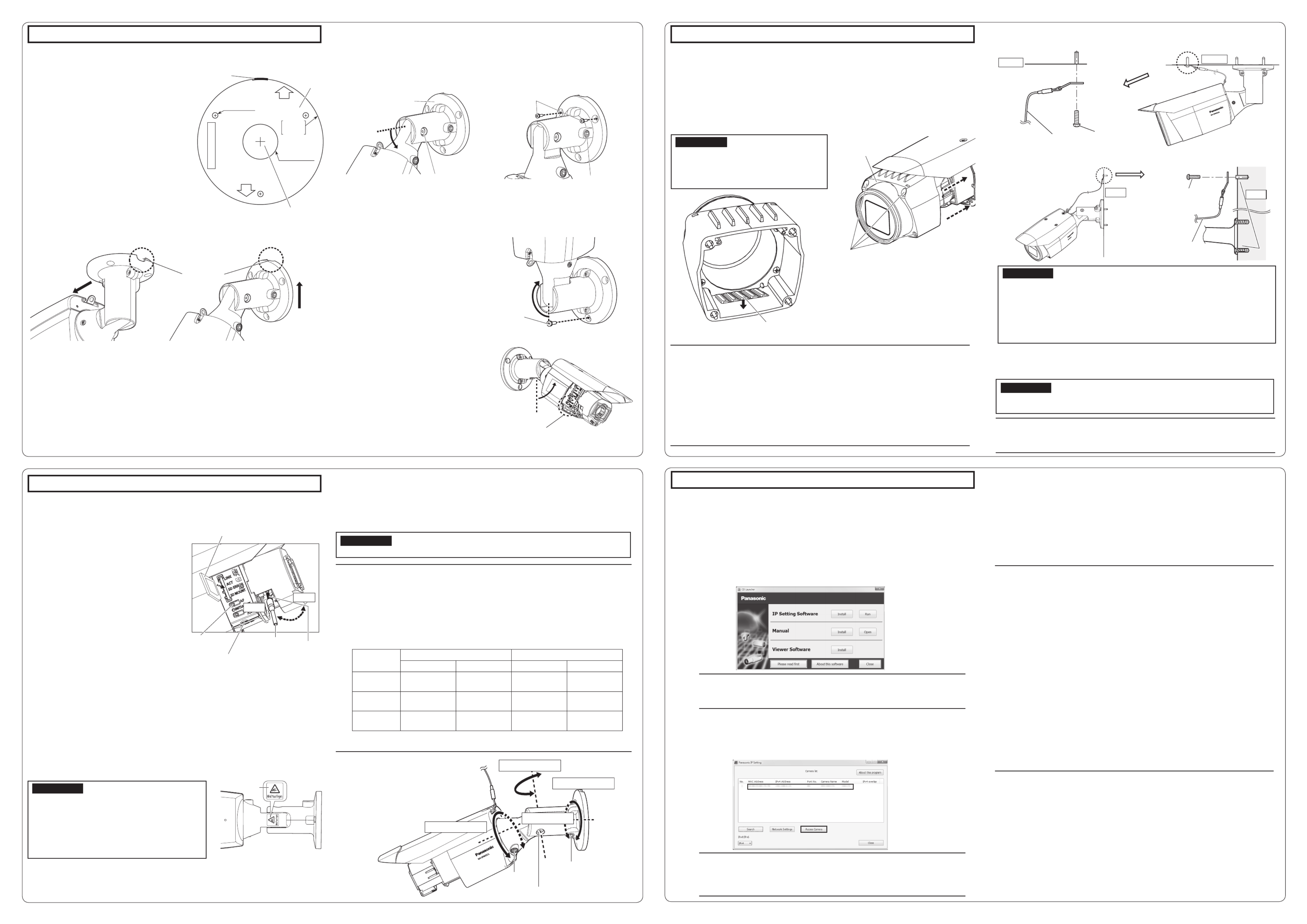
■
When the camera is installed to the ceiling
●Attach the template ( : accessory) to the A
ceiling with the FRONT mark of template
towards the same direction which the camera
is facing.
●Drill holes for securing the camera and wiring
as shown in the illustration to the right.
■
When the camera is mounted on the wall
●Attach template ( : accessory) onto the A
installation wall with the TOP mark facing
upward.
●Drill holes for securing the camera and wiring
as shown in the illustration to the upper right.
●When the side cable is installed, the Ethernet
cable can come out from the direction towards
the ceiling.
* After drilling holes at the ceiling or wall, remove
the template.
●Turn off each system’s power supply before making a connection. Before making
connections, prepare the required peripheral devices and cables.
●Connect the Ethernet cable coming from the camera and coming through the ceiling or
wall according to the instructions in “Making connections”. Waterproof the connections
according to the instructions in “Waterproof treatment for the cable joint sections”.
The following example describes the case when the camera is mounted on the wall.
Attach the camera body by following steps 1~4.
* In the following illustrations, the safety wire is omitted.
* Do not adjust the PAN
rotation part more than
±180 °. This may cause
cables to be wrenched.
1
Loosen the TILT lock screw by about
1 turn until the camera faces down-
ward and then temporarily tighten the
TILT lock screw.
1
Change the direction the camera is
facing from directly down to facing up
and temporarily fix the camera in
place.
2
Fit a pin cable (locally procured) to the
MONITOR OUT jack on the camera
and connect an adjustment monitor.
3 The camera faces upward and then
temporarily tighten the PAN lock screw.
After this, use the lower M4 screw
(locally procured) to secure the camera.
●M4 × 3 screws, Minimum pull-out
strength: 724 N {163 lbf} (per 1 pc.).
4
After fixing the camera, set the camera
back to downward as described in .2
2
Use the 2 upper M4 screws (locally
procured) to secure the camera.
And then loosen the PAN lock
screw about 1 turn.
Step 3 Fixing the camera
[1]
Paste the template (A: accessory) on the installation position, and
drill a securing and wiring hole
[2]
Connect the camera with an Ethernet cable
[3]
Fixing the camera
[4]
Connect the adjustment monitor to the camera
ഴ/TEMPLATE
TOP
FRONT
्ܰ
Outline
PAN rotation part
YAW rotation part
TILT rotation part
Camera arm part
YAW lock
screw
PAN lock screw
TILT lock screw
Cable access hole
Side cable
access hole
FRONT
direction
TOP
direction
Template
( :A accessory)
Side cable
access hole
Step 4 Adjusting the camera (continued)
4
,
5
,
6
,
7
4 After adjusting the focus by pressing the AF button, remove the adjustment
monitor.
7 Remove the protection sheet on the front cover.
5
Stick the desiccant ( : accessory) to the bottom sides inside the front cover and G
mount the front cover.
●Peel off the backing paper of the double-sided tape from the desiccant.
●As shown in the illustration below, stick the desiccant onto the bottom of the lens cover, and
then mount the front cover to the camera with the 4 fixing screws as soon as possible (with-
in 5 minutes).
* Fasten the front cover fixing screws along the diagonal direction.
6 Secure the safety wire ( : accessory) to the ceiling or wall.C
■ When the camera is installed to the ceiling
IMPORTANT:
●Once the front cover is installed, the camera may be slightly out of focus. After
installing the front cover, use the auto focus via the settings menu.
Note:
●When sticking the desiccant, make sure it will not spill over the front cover.
●Do not let the desiccant (G: accessory) get damp, nor touch it with wet hands.
● While adjusting the lens, do not let water drops drip into the lens cover or the camera.
●Do not stick the desiccant (G: accessory) until you have finished adjusting the field of view
and the camera focus. Do not unpack the desiccant too early; otherwise its performance
may be affected.
●Desiccant should be replaced after about 3 years. The effective period may be shortened
according to environment. Besides, when removing the front cover to adjust the camera
or process other operations, replace the desiccant with a new one.
Model No. of replacement part Desiccant 3CJ001261AAA
When the camera has been installed, remove the protection sheet from the front
cover. After removal, be sure not to touch the clear part of the front cover.
Note:
●When removing the camera, perform removal by following the installation proce-
dure in the reverse order.
Step 5 Configure the network settings
M6 bolt and nut
or anchor (locally
procured)
Safety wire
(C: accessory)
Ceiling
■ When the camera is mounted on the wall
Safety wire
(C: accessory)
M6 bolt and nut
or anchor (locally
procured)
Wall
Wall
<Ceiling mounting> <Wall mounting>
Camera mount
bracket
M4 × 2
(locally procured)
M4 × 3
∅25 mm {1"}
M4 (locally
procured)
MONITOR OUT jack
(Video Out terminal
Default:
For NTSC monitor)
PAN lock screw
TILT lock screw
Front cover
Front cover fixing
screws × 4
Desiccant (G: accessory)
Ceiling
The following are descriptions for when the camera with default settings is configured. If you are using fire-
wall software on your PC, the Setup Program may not be able to find any cameras on your network.
Configure the setting of the camera after temporarily invalidating the firewall software. Contact the network
administrator or your Internet service provider for information about configuring the settings of the network.
q Insert the provided CD-ROM into the CD-ROM drive of your PC.
w Click the [Run] button next to [IP Setting Software].
[Panasonic IP Setting] screen will be displayed. When a camera is found, information
about it, such as its MAC address and IP address, is displayed.
e Select the camera you want to congure, and click [Access Camera].
Note:
●Refer to “Using the CD-ROM” in the operating instructions on the provided
CD-ROM for further information about CDLauncher.
Note:
● When no image is displayed on the “Live” page, refer to the Troubleshooting in
the operating instructions on the provided CD-ROM.
●It is possible to enhance the network security by encrypting the access to camer-
as using the HTTPS function. Refer to the operating instructions on the provided
CD-ROM for how to configure the HTTPS settings.
●Click the [Setup] button on the “Live” page, the user authentication window will be
displayed. Enter the default user name and password as follows, and log in.
User name: admin
Password: 12345
●When changing settings related to the network settings, such as connection
mode, IP address, and subnet mask, click the [Network Settings] button in
[Panasonic IP Setting] screen as shown in step
e, then change each setting.
●Due to security enhancements in “IP Setting Software”, “Network settings” of the
camera to be configured cannot be changed when around 20 minutes have
passed after turning on the power of the camera. (When the effective period is set
to “20 min” in the “Easy IP Setup accommodate period”.)
However, settings can be changed after 20 minutes for cameras in the initial set
mode.
●“Network Camera Recorder with Viewer Software Lite” which supports live moni-
toring and recording images from multiple cameras is available. For further infor-
mation, refer to our website
(http://security.panasonic.com/pss/security/support/info.html).
Note:
●When cameras are displayed in [Panasonic IP Setting] screen, click the cam-
era with same MAC address as the MAC address printed on the camera that
you want to configure.
Conguring the camera so that it can be accessed from a PC r If the installation screen of the viewer software “Network Camera View 4S” is displayed,
follow the instructions of the wizard to start the installation. (The viewer software is in-
stalled from the camera.)
● The License Agreement will be displayed. Read the Agreement and choose “I accept
the term in the license agreement”, and click [OK].
●The launcher window will be displayed. If the launcher window is not displayed, double
click the “CDLauncher.exe” le on the CD-ROM.
●The “Live” page will be displayed.
●
If you cannot install the viewer software “Network Camera View 4S” or if images are not
displayed, click the [Install] button next to [Viewer Software] on the launcher window to
install the software.
●Perform the [Time & date] settings in the “Setup” - “Basic” page before using the camera.
IMPORTANT:
●Securely tighten the 4 front cover fixing
screws. Failure to do so may cause the cam-
era to fall or waterproof failure.
Recommended tightening torque: 0.59 N·m
{0.44 lbf·ft}
Warning label
Auto focus
(AF) button Zoom knob
MONITOR OUT jack
SD memory card
(Ensure that the label faces the lens.)
Auxiliary handle
( : accessory)F
TELE
WIDE
Specyfikacje produktu
| Marka: | Panasonic |
| Kategoria: | Kamera monitorująca |
| Model: | WV-SPW532L |
Potrzebujesz pomocy?
Jeśli potrzebujesz pomocy z Panasonic WV-SPW532L, zadaj pytanie poniżej, a inni użytkownicy Ci odpowiedzą
Instrukcje Kamera monitorująca Panasonic

2 Października 2024
10 Września 2024
8 Września 2024
2 Września 2024
28 Sierpnia 2024
24 Sierpnia 2024
23 Sierpnia 2024
20 Sierpnia 2024
19 Sierpnia 2024
18 Sierpnia 2024
Instrukcje Kamera monitorująca
- Kamera monitorująca Sony
- Kamera monitorująca Samsung
- Kamera monitorująca Tenda
- Kamera monitorująca Motorola
- Kamera monitorująca Stabo
- Kamera monitorująca Logitech
- Kamera monitorująca Xiaomi
- Kamera monitorująca Braun
- Kamera monitorująca Pioneer
- Kamera monitorująca TP-Link
- Kamera monitorująca Philips
- Kamera monitorująca Bosch
- Kamera monitorująca Gigaset
- Kamera monitorująca Hikvision
- Kamera monitorująca EZVIZ
- Kamera monitorująca Conceptronic
- Kamera monitorująca Canon
- Kamera monitorująca Crestron
- Kamera monitorująca Withings
- Kamera monitorująca Asus
- Kamera monitorująca Nedis
- Kamera monitorująca AG Neovo
- Kamera monitorująca Reolink
- Kamera monitorująca Boss
- Kamera monitorująca TRENDnet
- Kamera monitorująca Marquant
- Kamera monitorująca Toshiba
- Kamera monitorująca D-Link
- Kamera monitorująca August
- Kamera monitorująca Niceboy
- Kamera monitorująca Ring
- Kamera monitorująca Garmin
- Kamera monitorująca Imou
- Kamera monitorująca Blaupunkt
- Kamera monitorująca Grundig
- Kamera monitorująca APC
- Kamera monitorująca Honeywell
- Kamera monitorująca BLOW
- Kamera monitorująca Manhattan
- Kamera monitorująca Strong
- Kamera monitorująca Swann
- Kamera monitorująca Kwikset
- Kamera monitorująca Kodak
- Kamera monitorująca Cisco
- Kamera monitorująca ORNO
- Kamera monitorująca Broan
- Kamera monitorująca Moxa
- Kamera monitorująca Synology
- Kamera monitorująca Gembird
- Kamera monitorująca ZTE
- Kamera monitorująca Turing
- Kamera monitorująca Lindy
- Kamera monitorująca Minox
- Kamera monitorująca Zebra
- Kamera monitorująca DSC
- Kamera monitorująca JVC
- Kamera monitorująca ZyXEL
- Kamera monitorująca Trust
- Kamera monitorująca LogiLink
- Kamera monitorująca Furrion
- Kamera monitorująca Linksys
- Kamera monitorująca Google
- Kamera monitorująca Digitus
- Kamera monitorująca Vimar
- Kamera monitorująca V-TAC
- Kamera monitorująca Dahua Technology
- Kamera monitorująca Schneider
- Kamera monitorująca Eufy
- Kamera monitorująca Ricoh
- Kamera monitorująca Emos
- Kamera monitorująca AVMATRIX
- Kamera monitorująca Renkforce
- Kamera monitorująca Rollei
- Kamera monitorująca Marshall
- Kamera monitorująca Perel
- Kamera monitorująca Somfy
- Kamera monitorująca Uniden
- Kamera monitorująca Netgear
- Kamera monitorująca Thomson
- Kamera monitorująca DiO
- Kamera monitorująca Velleman
- Kamera monitorująca Ferguson
- Kamera monitorująca DataVideo
- Kamera monitorująca Delta Dore
- Kamera monitorująca Pyle
- Kamera monitorująca Intellinet
- Kamera monitorująca CRUX
- Kamera monitorująca Setti+
- Kamera monitorująca Waeco
- Kamera monitorująca Vivotek
- Kamera monitorująca Vtech
- Kamera monitorująca Speco Technologies
- Kamera monitorująca EtiamPro
- Kamera monitorująca Edimax
- Kamera monitorująca Petcube
- Kamera monitorująca ION
- Kamera monitorująca First Alert
- Kamera monitorująca AirLive
- Kamera monitorująca Maginon
- Kamera monitorująca EnGenius
- Kamera monitorująca SPC
- Kamera monitorująca Planet
- Kamera monitorująca Brilliant
- Kamera monitorująca Genie
- Kamera monitorująca LevelOne
- Kamera monitorująca Axis
- Kamera monitorująca Sanyo
- Kamera monitorująca Lorex
- Kamera monitorująca Control4
- Kamera monitorująca Milesight
- Kamera monitorująca Aluratek
- Kamera monitorująca Abus
- Kamera monitorująca Elro
- Kamera monitorująca Olympia
- Kamera monitorująca Hama
- Kamera monitorująca Marmitek
- Kamera monitorująca Ubiquiti Networks
- Kamera monitorująca Western Digital
- Kamera monitorująca Netatmo
- Kamera monitorująca Schwaiger
- Kamera monitorująca Promise Technology
- Kamera monitorująca GVI Security
- Kamera monitorująca AVer
- Kamera monitorująca ZKTeco
- Kamera monitorująca Netis
- Kamera monitorująca Extech
- Kamera monitorująca Denver
- Kamera monitorująca Anker
- Kamera monitorująca Allnet
- Kamera monitorująca Marshall Electronics
- Kamera monitorująca Orion
- Kamera monitorująca Yale
- Kamera monitorująca SereneLife
- Kamera monitorująca Ernitec
- Kamera monitorująca AVerMedia
- Kamera monitorująca MEE Audio
- Kamera monitorująca Genius
- Kamera monitorująca Trevi
- Kamera monitorująca Technaxx
- Kamera monitorująca Atlona
- Kamera monitorująca Hanwha
- Kamera monitorująca Overmax
- Kamera monitorująca Quantum
- Kamera monitorująca Y-cam
- Kamera monitorująca Grandstream
- Kamera monitorująca Raymarine
- Kamera monitorująca Powerfix
- Kamera monitorująca Avanti
- Kamera monitorująca Ikan
- Kamera monitorująca Alecto
- Kamera monitorująca Avidsen
- Kamera monitorująca JUNG
- Kamera monitorująca Burg Wächter
- Kamera monitorująca Foscam
- Kamera monitorująca Lumens
- Kamera monitorująca Monacor
- Kamera monitorująca Dörr
- Kamera monitorująca M-e
- Kamera monitorująca EVE
- Kamera monitorująca Smartwares
- Kamera monitorująca Adj
- Kamera monitorująca Qian
- Kamera monitorująca Arenti
- Kamera monitorująca Elmo
- Kamera monitorująca Vitek
- Kamera monitorująca Alfatron
- Kamera monitorująca UniView
- Kamera monitorująca Clas Ohlson
- Kamera monitorująca Laserliner
- Kamera monitorująca Megasat
- Kamera monitorująca REVO
- Kamera monitorująca BZBGear
- Kamera monitorująca BirdDog
- Kamera monitorująca KJB Security Products
- Kamera monitorująca HiLook
- Kamera monitorująca Profile
- Kamera monitorująca Aldi
- Kamera monitorująca Aritech
- Kamera monitorująca Acti
- Kamera monitorująca ACME
- Kamera monitorująca Flamingo
- Kamera monitorująca Caliber
- Kamera monitorująca Eminent
- Kamera monitorująca Sitecom
- Kamera monitorująca Exibel
- Kamera monitorująca Fortinet
- Kamera monitorująca KlikaanKlikuit
- Kamera monitorująca Trebs
- Kamera monitorująca Ednet
- Kamera monitorująca Steren
- Kamera monitorująca Flir
- Kamera monitorująca Buffalo
- Kamera monitorująca Arlo
- Kamera monitorująca Nest
- Kamera monitorująca Siedle
- Kamera monitorująca Hive
- Kamera monitorująca Switel
- Kamera monitorująca Chacon
- Kamera monitorująca InFocus
- Kamera monitorująca Hombli
- Kamera monitorująca Naxa
- Kamera monitorująca Konig
- Kamera monitorująca Valueline
- Kamera monitorująca BRK
- Kamera monitorująca QSC
- Kamera monitorująca Xavax
- Kamera monitorująca Vaddio
- Kamera monitorująca Gira
- Kamera monitorująca Interlogix
- Kamera monitorująca Boyo
- Kamera monitorująca IC Intracom
- Kamera monitorująca Iget
- Kamera monitorująca EverFocus
- Kamera monitorująca Adesso
- Kamera monitorująca Satel
- Kamera monitorująca POSline
- Kamera monitorująca Notifier
- Kamera monitorująca Hawking Technologies
- Kamera monitorująca Friedland
- Kamera monitorująca Nexxt
- Kamera monitorująca Monoprice
- Kamera monitorująca Watec
- Kamera monitorująca Beafon
- Kamera monitorująca Chuango
- Kamera monitorująca ETiger
- Kamera monitorująca Videcon
- Kamera monitorująca INSTAR
- Kamera monitorująca Provision ISR
- Kamera monitorująca Aqara
- Kamera monitorująca Advantech
- Kamera monitorująca Digital Watchdog
- Kamera monitorująca Ganz
- Kamera monitorująca AViPAS
- Kamera monitorująca ClearOne
- Kamera monitorująca Ebode
- Kamera monitorująca Oplink
- Kamera monitorująca Sonic Alert
- Kamera monitorująca Linear PRO Access
- Kamera monitorująca Summer Infant
- Kamera monitorująca SMC
- Kamera monitorująca Topica
- Kamera monitorująca Kogan
- Kamera monitorująca Iiquu
- Kamera monitorująca Verint
- Kamera monitorująca Brinno
- Kamera monitorująca Rostra
- Kamera monitorująca Caddx
- Kamera monitorująca Spyclops
- Kamera monitorująca EKO
- Kamera monitorująca Kguard
- Kamera monitorująca Woonveilig
- Kamera monitorująca Mobi
- Kamera monitorująca Surveon
- Kamera monitorująca Hollyland
- Kamera monitorująca Epcom
- Kamera monitorująca Indexa
- Kamera monitorująca Lutec
- Kamera monitorująca Whistler
- Kamera monitorująca ClearView
- Kamera monitorująca VideoComm
- Kamera monitorująca IMILAB
- Kamera monitorująca 3xLOGIC
- Kamera monitorująca Pelco
- Kamera monitorująca Leviton
- Kamera monitorująca Inkovideo
- Kamera monitorująca Pentatech
- Kamera monitorująca Weldex
- Kamera monitorująca SecurityMan
- Kamera monitorująca Canyon
- Kamera monitorująca CNB Technology
- Kamera monitorująca Tapo
- Kamera monitorująca Aigis
- Kamera monitorująca Exacq
- Kamera monitorująca Brickcom
- Kamera monitorująca Laxihub
- Kamera monitorująca Securetech
- Kamera monitorująca EFB Elektronik
- Kamera monitorująca NetMedia
- Kamera monitorująca Videotec
- Kamera monitorująca Illustra
- Kamera monitorująca Nivian
- Kamera monitorująca E-bench
- Kamera monitorująca Syscom
- Kamera monitorująca Tecno
- Kamera monitorująca Night Owl
- Kamera monitorująca Guardzilla
- Kamera monitorująca Astak
- Kamera monitorująca Blink
- Kamera monitorująca Milestone Systems
- Kamera monitorująca Zavio
- Kamera monitorująca Campark
- Kamera monitorująca IPX
- Kamera monitorująca Dedicated Micros
- Kamera monitorująca Hamlet
- Kamera monitorująca Annke
- Kamera monitorująca AVTech
- Kamera monitorująca Qoltec
- Kamera monitorująca Approx
- Kamera monitorująca Digimerge
- Kamera monitorująca Wisenet
- Kamera monitorująca Infortrend
- Kamera monitorująca Epiphan
- Kamera monitorująca Mach Power
- Kamera monitorująca Compro
- Kamera monitorująca Aida
- Kamera monitorująca Ikegami
- Kamera monitorująca Accsoon
- Kamera monitorująca Vimtag
- Kamera monitorująca Gewiss
- Kamera monitorująca Alula
- Kamera monitorująca Insteon
- Kamera monitorująca Costar
- Kamera monitorująca ALC
- Kamera monitorująca Security Labs
- Kamera monitorująca Comtrend
- Kamera monitorująca Seneca
- Kamera monitorująca Avigilon
- Kamera monitorująca American Dynamics
- Kamera monitorująca Vosker
- Kamera monitorująca Sentry360
- Kamera monitorująca Bea-fon
- Kamera monitorująca Owltron
- Kamera monitorująca Enabot
- Kamera monitorująca Luis Energy
- Kamera monitorująca Sir Gawain
- Kamera monitorująca VisorTech
- Kamera monitorująca Atlantis Land
- Kamera monitorująca B & S Technology
- Kamera monitorująca I3International
- Kamera monitorująca IDIS
- Kamera monitorująca Ecobee
- Kamera monitorująca Conbrov
- Kamera monitorująca HuddleCamHD
- Kamera monitorująca Mobotix
- Kamera monitorująca IOIO
- Kamera monitorująca BIRDFY
- Kamera monitorująca I-PRO
- Kamera monitorująca DVDO
- Kamera monitorująca TCP
- Kamera monitorująca Bolin Technology
- Kamera monitorująca Nextech
Najnowsze instrukcje dla Kamera monitorująca

28 Stycznia 2025
25 Stycznia 2025
17 Stycznia 2025
15 Stycznia 2025

13 Stycznia 2025

13 Stycznia 2025
13 Stycznia 2025

12 Stycznia 2025
12 Stycznia 2025
12 Stycznia 2025