Instrukcja obsługi Motu 828mk3 Hybrid
Motu
system hi-fi
828mk3 Hybrid
Przeczytaj poniżej 📖 instrukcję obsługi w języku polskim dla Motu 828mk3 Hybrid (128 stron) w kategorii system hi-fi. Ta instrukcja była pomocna dla 20 osób i została oceniona przez 2 użytkowników na średnio 4.5 gwiazdek
Strona 1/128

™
MOTU 828mk3 Hybrid
User Guide for Mac
1280 Massachusetts Avenue
Cambridge, MA 02138
Business voice: (617) 576-2760
Business fax: (617) 576-3609
Web site: www.motu.com
Tech support: www.motu.com/support

SAFETY PRECAUTIONS AND ELECTRICAL REQUIREMENTS
CAUTION! READ THIS SAFETY GUIDE BEFORE YOU BEGIN INSTALLATION OR OPERATION. FAILURE TO COMPLY WITH SAFETY INSTRUCTIONS
COULD RESULT IN BODILY INJURY OR EQUIPMENT DAMAGE.
HAZARDOUS VOLAGES: CONTACT MAY CAUSE ELECTRIC SHOCK OR BURN. TURN OFF UNIT BEFORE SERVICING.
WARNING: TO REDUCE THE RISK OF FIRE OR ELECTRICAL SHOCK, DO NOT EXPOSE THIS APPLIANCE TO RAIN OR OTHER MOISTURE.
CAUTION: TO REDUCE THE RISK OF ELECTRICAL SHOCK, DO NOT REMOVE COVER. NO USER-SERVICEABLE PARTS INSIDE. REFER SERVICING TO
QUALIFIED SERVICE PERSONNEL.
WARNING: DO NOT PERMIT FINGERS TO TOUCH THE TERMINALS OF PLUGS WHEN INSTALLING OR REMOVING THE PLUG TO OR FROM THE OUTLET.
WARNING: IF NOT PROPERLY GROUNDED THE MOTU 828mk3 COULD CAUSE AN ELECTRICAL SHOCK.
The MOTU 828mk3 is equipped with a three-conductor cord and grounding type plug which has a grounding prong, approved by Underwriters' Laboratories and the Canadian Standards Association.
This plug requires a mating three-conductor grounded type outlet as shown in Figure A below. If the outlet you are planning to use for the MOTU 828mk3 is of the two prong type, DO NOT REMOVE
OR ALTER THE GROUNDING PRONG IN ANY MANNER. Use an adapter as shown below and always connect the grounding lug to a known ground. It is recommended that you have a qualified
electrician replace the TWO prong outlet with a properly grounded THREE prong outlet. An adapter as illustrated below in Figure B is available for connecting plugs to two-prong receptacles.
WARNING: THE GREEN GROUNDING LUG EXTENDING FROM THE ADAPTER MUST BE CONNECTED TO A PERMANENT GROUND SUCH AS TO A
PROPERLY GROUNDED OUTLET BOX. NOT ALL OUTLET BOXES ARE PROPERLY GROUNDED.
If you are not sure that your outlet box is properly grounded, have it checked by a qualified electrician. NOTE: The adapter illustrated is for use only if you already have a properly grounded two-prong
receptacle. Adapter is not allowed in Canada by the Canadian Electrical Code. Use only three wire extension cords which have three-prong grounding type plugs and three-prong receptacles which
will accept the MOTU 828mk3 plug.
IMPORTANT SAFEGUARDS
1. Read these instructions. All the safety and operating instructions should be read before operating the 828mk3.
2. Keep these instructions. These safety instructions and the 828mk3 owner’s manual should be retained for future reference.
3. Heed all warnings. All warnings on the 828mk3 and in the owner’s manual should be adhered to.
4. Follow all Instructions. All operating and use instructions should be followed.
5. Do not use the 828mk3 near water.
6. Cleaning - Unplug the 828mk3 from the computer and clean only with a dry cloth. Do not use liquid or aerosol cleaners.
7. Ventilation - Do not block any ventilation openings. Install in accordance with the manufacturer’s instructions.
8. Heat - Do not install the 828mk3 near any heat sources such as radiators, heat registers, stoves, or another apparatus (including an amplifier) that produces heat.
9. Overloading - Do not overload wall outlets and extension cords as this can result in a risk of fire or electrical shock.
10. Grounding - Do not defeat the safety purpose of the polarized or grounding-type plug. A polarized plug has two blades with one wider than the other. A grounding-type plug has two blades and a third grounding prong. The wide blade
or the third prong are provided for your safety. If the provided plug does not fit into your outlet, consult and electrician for replacement of the obsolete outlet.
11. Power cord - Protect the 828mk3 power cord from being walked on or pinched by items placed upon or against them. Pay particular attention to cords and plugs, convenience receptacles, and the point where they exit from the unit.
12. Power switch - Install the 828mk3 so that the power switch can be accessed and operated at all times.
13. Disconnect - The main plug is considered to be the disconnect device for the 828mk3 and shall remain readily operable.
14. Accessories - Only use attachments/accessories specified by the manufacturer.
15. Placement - Use only with the cart, stand, tripod, bracket or table specified by the manufacturer, or sold with the 828mk3. When a cart is used, use caution when moving the cart/apparatus combination to avoid injury from tip-over.
16. Surge protection - Unplug the 828mk3 during lightning storms or when unused for long periods of time.
17. Servicing - Refer all servicing to qualified service personnel. Servicing is required when the 828mk3 has been damaged in any way, such as when a power-supply cord or plug is damaged, liquid has been spilled or objects have fallen
into the 828mk3, the 828mk3 has been exposed to rain or moisture, does not operate normally, or has been dropped.
18. Power Sources - Refer to the manufacturer’s operating instructions for power requirements. Be advised that different operating voltages may require the use of a different line cord and/or attachment plug.
19. Installation - Do not install the 828mk3 in an unventilated rack, or directly above heat-producing equipment such as power amplifiers. Observe the maximum ambient operating temperature listed below.
20. Power amplifiers- Never attach audio power amplifier outputs directly to any of the unit’s connectors.
21. Replacement Parts - When replacement parts are required, be sure the service technician has used replacement parts specified by the manufacturer or have the same characteristics as the original part. Unauthorized substitutions
may result in fire, electric shock or other hazards.
22. Safety Check - Upon completion of any service or repairs to this MOTU 828mk3, ask the service technician to perform safety checks to determine that the product is in safe operating conditions.
ENVIRONMENT
Operating Temperature: 10°C to 40°C (50°F to 104°)
TO REDUCE THE RISK OF ELECTRICAL SHOCK OR FIRE
Do not handle the power cord with wet hands. Do not pull on the power cord when disconnecting it from an AC wall outlet. Grasp it by the plug. Do not expose this apparatus to rain or moisture. Do not place objects containing liquids on it.
AC INPUT
100 - 240VAC ~ • 50 / 60Hz • 20 Watts.
3-prong plug
Grounding prong
Properly grounded 3-prong outlet
Grounding lug
Screw
3-prong plug
Adapter
Make sure this is connected to
a known ground.
Two-prong receptacle
Figure A Figure B

III
Contents
5Quick Reference: 828mk3 Front Panel
6Quick Reference: 828mk3 Rear Panel
7Quick Reference: MOTU Audio Setup
9About the 828mk3
15 Packing List and System Requirements
17 Installing the 828mk3 Hardware
33 Installing the 828mk3 Software
37 MOTU Audio Setup
43 Front Panel Operation
53 Digital Performer and AudioDesk
59 Other Mac OS X Audio Software
67 Reducing Monitoring Latency
73 CueMix FX
119 MOTU SMPTE Setup
123 Troubleshooting
125 Index

About the Mark of the Unicorn License Agreement and
Limited Warranty on Software
TO PERSONS WHO PURCHASE OR USE THIS PRODUCT: carefully read all the
terms and conditions of the “click-wrap” license agreement presented to you when
you install the software. Using the software or this documentation indicates your
acceptance of the terms and conditions of that license agreement.
Mark of the Unicorn, Inc. (“MOTU”) owns both this program and its documentation.
Both the program and the documentation are protected under applicable copyright,
trademark, and trade-secret laws. Your right to use the program and the
documentation are limited to the terms and conditions described in the license
agreement.
Reminder of the terms of your license
This summary is not your license agreement, just a reminder of its terms. The actual
license can be read and printed by running the installation program for the software.
That license agreement is a contract, and clicking “Accept” binds you and MOTU to
all its terms and conditions. In the event anything contained in this summary is
incomplete or in conflict with the actual click-wrap license agreement, the terms of the
click-wrap agreement prevail.
YOU MAY: (a) use the enclosed program on a single computer; (b) physically transfer
the program from one computer to another provided that the program is used on only
one computer at a time and that you remove any copies of the program from the
computer from which the program is being transferred; (c) make copies of the
program solely for backup purposes. You must reproduce and include the copyright
notice on a label on any backup copy.
YOU MAY NOT: (a) distribute copies of the program or the documentation to others;
(b) rent, lease or grant sublicenses or other rights to the program; (c) provide use of
the program in a computer service business, network, time-sharing, multiple CPU or
multiple user arrangement without the prior written consent of MOTU; (d) translate,
adapt, reverse engineer, decompile, disassemble, or otherwise alter the program or
related documentation without the prior written consent of MOTU.
MOTU warrants to the original licensee that the disk(s) on which the program is
recorded be free from defects in materials and workmanship under normal use for a
period of ninety (90) days from the date of purchase as evidenced by a copy of your
receipt. If failure of the disk has resulted from accident, abuse or misapplication of the
product, then MOTU shall have no responsibility to replace the disk(s) under this
Limited Warranty.
THIS LIMITED WARRANTY AND RIGHT OF REPLACEMENT IS IN LIEU OF,
AND YOU HEREBY WAIVE, ANY AND ALL OTHER WARRANTIES, BOTH
EXPRESS AND IMPLIED, INCLUDING BUT NOT LIMITED TO WARRANTIES
OF MERCHANTABILITY AND FITNESS FOR A PARTICULAR PURPOSE. THE
LIABILITY OF MOTU PURSUANT TO THIS LIMITED WARRANTY SHALL BE
LIMITED TO THE REPLACEMENT OF THE DEFECTIVE DISK(S), AND IN NO
EVENT SHALL MOTU OR ITS SUPPLIERS, LICENSORS, OR AFFILIATES BE
LIABLE FOR INCIDENTAL OR CONSEQUENTIAL DAMAGES, INCLUDING
BUT NOT LIMITED TO LOSS OF USE, LOSS OF PROFITS, LOSS OF DATA OR
DATA BEING RENDERED INACCURATE, OR LOSSES SUSTAINED BY THIRD
PARTIES EVEN IF MOTU HAS BEEN ADVISED OF THE POSSIBILITY OF
SUCH DAMAGES. THIS WARRANTY GIVES YOU SPECIFIC LEGAL RIGHTS
WHICH MAY VARY FROM STATE TO STATE. SOME STATES DO NOT ALLOW
THE LIMITATION OR EXCLUSION OF LIABILITY FOR CONSEQUENTIAL
DAMAGES, SO THE ABOVE LIMITATION MAY NOT APPLY TO YOU.
Update Policy
In order to be eligible to obtain updates of the program, you must complete and return
the attached Mark of the Unicorn Purchaser Registration Card to MOTU.
Copyright Notice
Copyright © 2011, 2010, 2009, 2008, 2007, 2006, 2005, 2004, 2003 by Mark of the
Unicorn, Inc. All rights reserved. No part of this publication may be reproduced,
transmitted, transcribed, stored in a retrieval system, or translated into any human or
computer language, in any form or by any means whatsoever, without express
written permission of Mark of the Unicorn, Inc., 1280 Massachusetts Avenue,
Cambridge, MA, 02138, U.S.A.
Limited Warranty on Hardware
Mark of the Unicorn, Inc. and S&S Research (“MOTU/S&S”) warrant this equipment
against defects in materials and workmanship for a period of TWO (2) YEARS from
the date of original retail purchase. This warranty applies only to hardware products;
MOTU software is licensed and warranted pursuant to separate written statements.
If you discover a defect, first write or call Mark of the Unicorn at (617) 576-2760 to
obtain a Return Merchandise Authorization Number. No service will be performed on
any product returned without prior authorization. MOTU will, at its option, repair or
replace the product at no charge to you, provided you return it during the warranty
period, with transportation charges prepaid, to Mark of the Unicorn, Inc., 1280
Massachusetts Avenue, MA 02138. You must use the product’s original packing
material for in shipment, and insure the shipment for the value of the product. Please
include your name, address, telephone number, a description of the problem, and
the original, dated bill of sale with the returned unit and print the Return Merchandise
Authorization Number on the outside of the box below the shipping address.
This warranty does not apply if the equipment has been damaged by accident,
abuse, misuse, or misapplication; has been modified without the written permission
of MOTU, or if the product serial number has been removed or defaced.
ALL IMPLIED WARRANTIES, INCLUDING IMPLIED WARRANTIES OF
MERCHANTABILITY AND FITNESS FOR A PARTICULAR PURPOSE, ARE
LIMITED IN DURATION TO TWO (2) YEARS FROM THE DATE OF THE
ORIGINAL RETAIL PURCHASE OF THIS PRODUCT.
THE WARRANTY AND REMEDIES SET FORTH ABOVE ARE EXCLUSIVE
AND IN LIEU OF ALL OTHERS, ORAL OR WRITTEN, EXPRESS OR IMPLIED.
No MOTU/S&S dealer, agent, or employee is authorized to make any modification,
extension, or addition to this warranty.
MOTU/S&S ARE NOT RESPONSIBLE FOR SPECIAL, INCIDENTAL, OR
CONSEQUENTIAL DAMAGES RESULTING FROM ANY BREACH OF
WARRANTY, OR UNDER ANY LEGAL THEORY, INCLUDING LOST PROFITS,
DOWNTIME, GOODWILL, DAMAGE OR REPLACEMENT OF EQUIPMENT
AND PROPERTY AND COST OF RECOVERING REPROGRAMMING, OR
REPRODUCING ANY PROGRAM OR DATA STORED IN OR USED WITH
MOTU/S&S PRODUCTS.
Some states do not allow the exclusion or limitation of implied warranties or liability for
incidental or consequential damages, so the above limitation or exclusion may not
apply to you. This warranty gives you specific legal rights, and you may have other
rights which vary from state to state.
MOTU, AudioDesk, Mark of the Unicorn and the unicorn silhouette logo are
trademarks of Mark of the Unicorn, Inc.
This equipment has been type tested and found to comply with the limits for a class B digital device,
pursuant to Part 15 of the FCC Rules. These limits are designed to provide reasonable protection
against harmful interference in a residential installation. This equipment generates, uses, and can
radiate radio frequency energy and, if not installed and used in accordance with the instruction manual,
may cause harmful interference to radio communications. However, there is no guarantee that
interference will not occur in a particular installation. If this equipment does cause interference to radio
or television equipment reception, which can be determined by turning the equipment off and on, the
user is encouraged to try to correct the interference by any combination of the following measures:
• Relocate or reorient the receiving antenna
• Increase the separation between the equipment and the receiver
• Plug the equipment into an outlet on a circuit different from that to which the receiver is connected
If necessary, you can consult a dealer or experienced radio/television technician for additional
assistance.
PLEASE NOTE: only equipment certified to comply with Class B (computer input/output devices,
terminals, printers, etc.) should be attached to this equipment, and it must have shielded interface
cables in order to comply with the Class B FCC limits on RF emissions.
WARNING: changes or modifications to this unit not expressly approved by the party
responsible for compliance could void the user's authority to operate the equipment.

Quick Reference: 828mk3 Front Panel
The phone jack labeled (MAIN) is a standard quarter-inch stereo
headphone jack. Its output is hard-wired to mirror the XLR main outs on
the rear panel. From the factory, the MASTER VOL knob above it controls
the main outs and this jack, but MASTER VOL can be programmed to
control any combination of outputs. See “The Monitor Group” on
page 96 for details. Push the knob once to view the current volume
setting in the LCD display; push it again to mute the monitor group; push
a third time to return to the previous volume. Note: if the Monitor group
is programmed to not include the main outs, the MASTER VOL knob will
no longer control the volume of this phone jack, either.
These round LEDs indicate
signal presence on the 8 rear-
panel TRS analog and SPDIF
outputs. Their threshold is
around -42 dB. They do not
indicate clipping in any way;
use your host audio software
level meters to calibrate
output levels.
The multi-purpose backlit LCD shows
system settings or CueMix FX
settings, depending on which knobs
you turn. The labels above and below
the LCD refer to the four digital rotary
encoders to the left of the LCD. These
knobs let you access and program all
settings in the 828mk3.
These lights indicate the global
sample rate at which the 828mk3
is operating. Use the MOTU Audio
Setup software to set the sample
rate or to choose an external clock
source, from which the sample rate
will be derived. When no clock
signal is currently present, one of
these LEDs flashes rapidly.
FireWire and USB are “plug-
and-play” protocols. That
means that you can turn off
the 828mk3 and turn it back
on without restarting your
computer.
These two trim knobs provide approximately 53 dB of gain for the lo-Z XLR mic input and the hi-Z TRS guitar/instrument input. Both
inputs have preamps, so you can plug just about anything into them: a microphone, a guitar, a synth — but don’t plug in a +4 signal
here (due to the preamps): use a rear-panel TRS input instead. Use the trim knob and the “MIC” input level meters over in the metering
section to calibrate the input signal level. The meters cover both the TRS and XLR input. These mic inputs are also equipped with the
828mk3’s V-Limit™ hardware limiter, which provides an additional +12 dB of headroom above zero with no clipping or digital distor-
tion. See “Mic/guitar inputs meters with V-Limit™ compressor” on page 44 for details.
These XLR/TRS combo jacks accept either a mic cable or
a quarter-inch guitar cable. Both the low-impedance
XLR jack and the high-impedance TRS jack are
equipped with a preamp (so don’t connect a +4 line
level XLR cable!). For the Mic (XLR) input, push the TRIM
encoder to toggle a 20 dB pad; push and hold to toggle
48V phantom power. The Precision Digital Trim™ knob
provides 53 dB of gain. Use the rear panel sends to
route these inputs to your favorite outboard gear. Use
any rear-panel input as a return.
From the factory, the
PHONES jack is a discrete
output (at 44.1/48 kHz),
but it can mirror any other
output pair (digital or
analog). For example, at
88.2/96 kHz, it defaults to
mirroring the main outs.
As the primary phone jack,
it has its own dedicated
volume knob.
Push the CHANNEL knob repeat-
edly to cycle among the four
main sections of the mixer: mix
busses, inputs, outputs and the
reverb module. Push the PARAM
knob to enter the SETUP menu,
which provides global 828mk3
settings, such as the global
sample rate, etc.
This section controls the 828mk3’s built-in CueMix FX mixer and
effects. There are eight stereo mix busses: each bus mixes all
inputs (or any subset you wish) to a stereo output of your choice.
You can apply EQ, compression, and reverb to inputs, outputs and
mix busses. The four knobs to the left of the LCD correspond
directly to the four labeled sections of the LCD. Use the CHANNEL
knob to choose the input, output or mix you wish to edit. Push it to
switch among inputs, outputs and busses, then turn it to choose
the desired channel or bus. Use the PAGE, PARAM and VALUE knobs
to access the mix settings for the chosen channel.
This bank of
input meters
is for the 8
analog TRS
input jacks on
the rear panel.
This section provides two ten-segment meters for the two front-panel mic/guitar inputs. The
meters show input levels from -42 to -1 in the first column of LEDs, plus an additional range in a
second column from zero to +12 dB (including clip). Both inputs are equipped with V-Limit™, a
hardware limiter. With the limiter turned off, signals that hit zero or above will clip (a hard digital
clip). However, with V-Limit turned on, signals can go as high as +12 dB above zero with no
digital clipping. If the signal then goes above +12 dB, it will clip, even with V-Limit engaged.
When the 828mk3 is resolving
to SMPTE time code, the LOCK/
TACH LED glows when lockup
has been achieved. The ADAT
and MIDI LEDs blink when there
is optical audio or MIDI activity,
respectively.
5-segment
metering for the
main outs. Use
the MASTER VOL
knob to control
output level.
4-segment
metering for
SPDIF input.
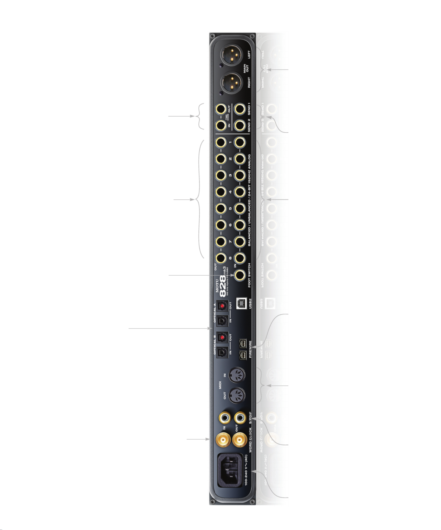
Quick Reference: 828mk3 Rear Panel
Connect the 828mk3 to the computer
here via either FireWire or USB2, using
either the standard 1394 FireWire B or
USB cable provided with your 828mk3.
If you use FireWire, you can also use the
second FireWire port to daisy-chain up
to four MOTU FireWire audio interfaces
to a single FireWire bus, or connect
other FireWire devices. Keep in mind
that the 828mk3 uses more FireWire bus
bandwidth when one or both optical
banks are enabled, or when it operates
at higher sample rates. These operating
configurations will limit the number of
devices you can daisy chain on a single
FireWire bus. For details, see “Connect-
ing multiple MOTU FireWire interfaces”
on page 29.
These jacks provide
stereo, 24-bit S/PDIF
digital input and
output at all
supported sample
rates (up to 96 kHz).
These two XLR jacks serve as the
828mk3’s main outputs. You can connect
them to a set of powered studio monitors
and then control the volume from the
front panel MASTER VOL knob.
To hear audio playback from your host
audio software on these main outs,
assign the audio tracks (and master
fader) to these main outs. You can also
use CueMix FX to monitor live 828mk3
inputs here as well.
Equipped with 24-bit 192 kHz converters,
these 8 analog inputs are gold-plated,
balanced TRS (tip/ring/sleeve) quarter-inch
connectors that can also accept an unbal-
anced plug. They do not have microphone
preamps, so they are best used for synthe-
sizers, drum machines, effects processors,
and other instruments with line level signals
(either -10 dB or +4 dB). These inputs are
also equipped with the 828mk3’s Precision
Digital Trim™ feature: digitally controlled
analog trims that let you adjust input level
in 1 dB increments from either front panel
LCD or the included CueMix FX software. The
trim can be adjusted over a range of -96 to
+22 dB.
These two quarter-inch
balanced TRS send
outputs supply the pre
amplified input signal
from the mic/guitar/
instrument inputs on
the front panel. Use
them to insert your
favorite compressor, EQ,
reverb or other
outboard effect. Use
any TRS input as a
return.
The 828mk3’s eight analog outputs are
gold-plated, balanced +4dB TRS (tip/
ring/sleeve) quarter-inch connectors
that can also accept an unbalanced plug.
They are equipped with 24-bit 192 kHz
converters.
These optical digital I/O connectors can be connected either to an ADAT-compatible “lightpipe” device (such as a digital mixer) or to a S/PDIF optical
(“TOSLink”) compatible device, such as an effects processor or DAT machine. Be sure to set the format in the MOTU Audio Setup software (or using the front
panel LCD). (see “Optical input/output” on page 41) for details.) ADAT optical supplies eight channels of 24-bit digital I/O per bank (4 channels per bank
at 96kHz). TOSLink is stereo at sample rates up to 96 kHz.
One special note: you can choose independent formats for each bank, A and B, as well as IN and OUT within each bank. For example, you could choose
ADAT for the optical A IN (for, say, eight channels of input from your digital mixer) and stereo TOSLink for the optical A OUT (for, say, your DAT machine).
Connect a standard foot switch
here for hands-free punch-in and
punch-out during recording. For
details about how to set this up,
see “Enable Pedal” on page 42.
These are standard BNC word clock jacks. Use them for
a variety of applications, such as for digital transfers
with devices that cannot slave to the clock supplied by
their digital I/O connection with the 828mk3.
When the 828mk3 is operating at a high sample rate
(88.2 or 96 kHz), you can force the word clock output
rate (via software or the front panel) to 44.1 or 48 kHz.
Connect a MIDI device here
using standard MIDI cables.
Connect the 828mk3’s MIDI OUT
port to the MIDI IN port on the
other device. Conversely,
connect the 828mk3’s MIDI IN
port to the MIDI OUT port on the
other device. You can connect
different devices to each port,
such as a controller device to
the IN port and a sound module
to the OUT port. You can also
daisy-chain MIDI devices, but
be sure to manage their MIDI
channels (so that they don’t
receive or transmit on the same
channel).
These are quarter-inch analog
SMPTE input and output jacks. Use
them to resolve the 828mk3
directly to time code and transmit
time code to other devices.
The 828mk3 is
equipped with an
auto-switching
international
power supply.
7
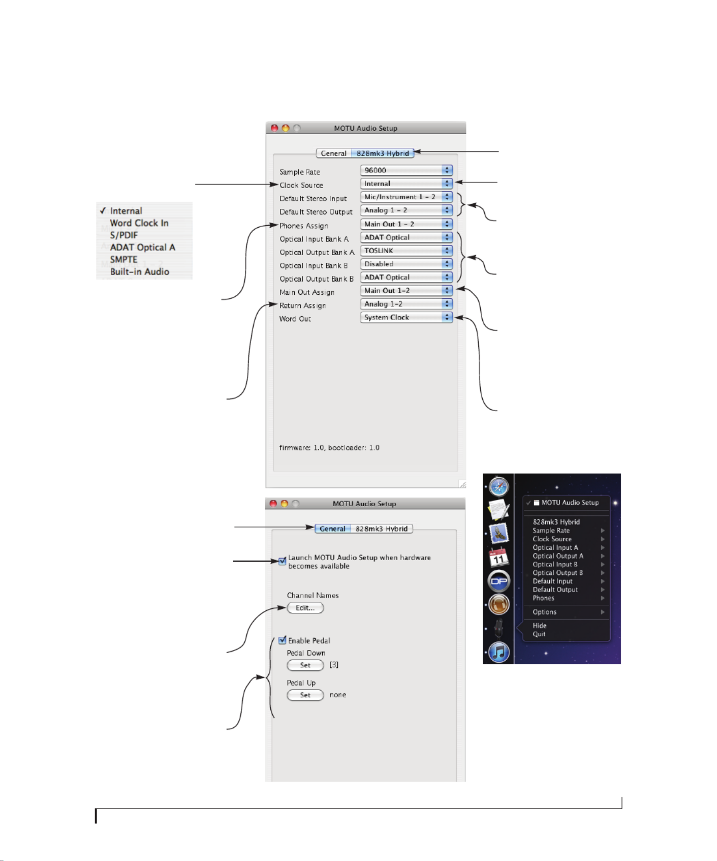
Quick Reference: MOTU Audio Setup
The 828mk3 driver provides a stereo return
back to the computer. This return feeds the
signal on any 828mk3 output pair directly
back to the computer, where you can record,
process, monitor or otherwise use it. This is a
great way to “bounce” full mixes, complete
with live audio routed through the 828mk3
only, back into the computer.
Determines the clock source for your
828mk3. If you’re just using the analog
ins and outs, set this to ‘Internal’. The
other settings are for digital transfers
via S/PDIF or optical ports, or for
slaving the 828mk3 to word clock.
Specifies the stereo input and output
pair when the 828mk3 is chosen for
Mac OS X audio I/O.
Choose the global sample rate for the
system here.
If you are running an 828mk3 interface
at a high sample rate (88.2, 96, 176.4 or
192 kHz), this option appears in the
interface tab. It lets you choose a word
clock output rate that either matches
the global sample rate (e.g. 96kHz) or
reduces it to the corresponding 1x rate
(e.g. 48kHz instead of 192 kHz).
This menu lets you choose what you will
hear from the PHONES jack. To mirror the
main outs, choose Main Out 1-2. Or you can
mirror any other output pair. To hear the
phones as their own independent output,
choose Phones 1-2 (at 44.1 or 48 kHz. At
higher sample rates, the phones must
mirror any other available output pair.)
Click the tabs to access general MOTU
FireWire and USB interface settings or
settings specific to the 828mk3 (or
other connected interface.)
Check this option if you would like the MOTU
Audio Setup icon to appear in the application
dock as soon as a MOTU FireWire or USB inter-
face is detected (switched on, plugged in,
etc.)
In the standard Mac OS X fashion, the
console appears in the dock when you
launch it. If the Launch option is checked (as
shown above), the icon appears as soon as
you switch on your 828mk3 interface. If you
click and hold on the dock icon (instead of
clicking it) or control-click, a menu of
hardware settings appears as shown to the
right. You can view and configure any
hardware settings from this menu, without
opening the console window.
Click the General tab to access these settings.
Each optical bank can be configured
independently ADAT or TOSLink. Disable
them when not in use to conserve DSP
and bus bandwidth.
Choose the output pair you would like
the main outs to mirror, or choose Main
Outs to operate them as their own
independent pair (at sample rates up to
96 kHz).
If you have a foot switch connected to the
828mk3, these settings let you map the foot
switch to any computer keyboard key for
both the up and down position. For details
about how to set this up, see “Enable Pedal”
on page 42.
This button opens another dialog that lets
you assign your own customized names to
each 828mk3 input and output. For example,
if you have a lead vocal mic plugged into
input 1, you could name it “Lead Vox”. Your
customized names then appear in your host
audio application (if it supports Core Audio
input naming).

8

CHAPTER
9
1About the 828mk3
Overview . . . . . . . . . . . . . . . . . . . . . . . . . . . . . . . . . . . . . . . . . . . . . .9
The 828mk3 Rear Panel. . . . . . . . . . . . . . . . . . . . . . . . . . . . . . 10
The 828mk3 Front Panel. . . . . . . . . . . . . . . . . . . . . . . . . . . . . 12
16-bit and 24-bit recording . . . . . . . . . . . . . . . . . . . . . . . . . . 13
CueMix FX 32-bit floating point mixing and effects. . 13
AudioDesk. . . . . . . . . . . . . . . . . . . . . . . . . . . . . . . . . . . . . . . . . . . 14
Digital Performer . . . . . . . . . . . . . . . . . . . . . . . . . . . . . . . . . . . . 14
Other Host Audio Software . . . . . . . . . . . . . . . . . . . . . . . . . . 14
OVERVIEW
The 828mk3 is a hybrid FireWire USB2 audio
interface for Mac and Windows with on-board
effects and mixing that offers 28 inputs and 30
outputs at 44.1 or 48 kHz. Both analog and digital
I/O are offered at sample rates up to 96 kHz, and
analog recording and playback is offered at rates up
to 192 kHz. All inputs and outputs can be accessed
simultaneously. The 828mk3 consists of a standard
19-inch, single-space, rack-mountable I/O unit
that connects directly to a computer via a standard
FireWire or USB cable.
The 828mk3 offers the following main features:
■Universal computer connectivity via FireWire or
high-speed USB2
■Eight 24-bit analog quarter-inch (TRS) inputs
■Eight 24-bit analog quarter-inch (TRS) outputs
■Two combo XLR/TRS mic/guitar inputs with
preamps, individual sends, 48V phantom power,
20 dB pad, and Precision Digital Trim™
■Two XLR main outputs
■Operation on all analog I/O at standard sample
rates up to 192 kHz
■Digitally controlled analog trim for all analog
inputs
■Two banks of optical digital I/O that provide 16
channels of ADAT optical at 48 kHz, 8 channels of
S/MUX optical I/O at 96 kHz or two banks of
stereo TOSLink at rates up to 96 kHz
■RCA S/PDIF at sample rates up to 96 kHz
■Word clock I/O
■MIDI I/O
■On-board SMPTE synchronization with
dedicated SMPTE I/O jacks
■Foot switch for hands-free punch-in/out
■Two headphone jacks with independent volume
control
■Programmable master volume knob
■CueMix™ FX no-latency mixing, monitoring
and effects processing
■Front-panel LCD programming for the mixer
and all other settings
■Extensive front panel metering and status LEDs
■Auto-switching international power supply
■Stand-alone operation
■Mac and Windows drivers for multi-channel
operation and across-the-board compatibility with
any audio software on current Mac and Windows
systems
■AudioDesk™, full-featured audio workstation
software for Mac OS X that supports both 16-bit
and 24-bit recording

A B O U T T H E 8 2 8 M K 3
10
With a variety of I/O formats, mic preamps, no-
latency mixing and processing of live input and
synchronization capabilities, the 828mk3 is a
complete, portable “studio in a box” when used
with a Mac or Windows computer.
THE 828MK3 REAR PANEL
The 828mk3 rear panel has the following
connectors:
■Eight gold-plated, balanced quarter-inch (TRS)
analog outputs (with 24-bit 192 kHz converters)
■Eight gold-plated, balanced quarter-inch (TRS)
analog inputs (with 24-bit 192 kHz converters)
■Two XLR “main” analog outputs with 24-bit
192 kHz converters
■Two gold-plated, balanced quarter-inch (TRS)
analog sends (for the front-panel mic/guitar
inputs)
■Gold-plated balanced TRS quarter-inch analog
in/out dedicated for SMPTE time code
■Two sets of optical connectors (in and out),
individually switchable among ADAT optical
“lightpipe”, 96 kHz S/MUX optical or S/PDIF
“TOSLink”
■RCA S/PDIF in/out
■MIDI IN and MIDI OUT
■Word clock in/out
■Foot pedal jack
■Two 1394 FireWire B connectors
■One high-speed USB2 connector
28 inputs and 30 outputs
All 828mk3 inputs and outputs can be used simul-
taneously, for a total of 28 inputs and 30 outputs
when operating at 44.1 or 48 kHz:
* The phone jack below the MASTER VOL knob is
hard-wired to (mirrors) the XLR main outs. The
PHONES output can operate as an independent
output pair, or it can mirror any other 828mk3
output pair, such as the main outs.
† The 828mk3 optical connectors support several
standard optical I/O formats, which provide
varying channel counts. See “Optical” on page 11
for details about optical bank operation.
With the exception of the phone jack on the front
panel labeled “(MAIN)”, all inputs and outputs are
discrete. For example, using a mic input does not
“steal” an input from the TRS analog I/O bank.
Analog
All analog inputs are equipped with 24-bit 192 kHz
A/D converters. All analog outputs have 24-bit
192 kHz D/A converters. All audio is transferred to
and from the computer in a 24-bit data stream.
All quarter-inch analog inputs can accept either a
balanced or unbalanced plug.
Connection Input Output
Analog 24-bit 192 kHz on bal/unbal TRS 8 8
Mic/guitar 24-bit 192 kHz on XLR/TRS combo 2 -
Main outputs 24-bit 192 kHz on XLR - stereo
Headphone output* - stereo
ADAT optical digital† 16 16
RCA S/PDIF 24-bit 96kHz digital stereo stereo
Total 28 30

A B O U T T H E 8 2 8 M K 3
11
The quarter-inch outputs are referenced to a +4
dBu line level output signal. The inputs have
+22 dB of input gain and -96 dB of cut, allowing
them to accommodate both -10 dBu and +4 dBu
level signals.
Precision Digital Trim™
All of the 828mk3’s analog inputs are equipped
with digitally controlled analog trims, adjustable in
1 dB increments. The mic/guitar input trims can be
adjusted using front-panel digital rotary encoders
that provide feedback in the front panel LCD with
up to 53 dB of boost. All analog inputs, including
eight rear-panel TRS analog inputs, can be
trimmed using the front panel LCD or using the
828mk3’s included CueMix FX control software for
Mac and Windows. This gives you finely-tuned
control of trim settings for synths, effects modules,
and a wide variety of analog inputs for optimum
levels. Different trim configurations can then be
saved as preset configurations for instant recall.
Mic/guitar sends
Before A/D conversion, the pre-amplified signal
from each front-panel mic/guitar input is routed to
one of the two rear-panel quarter-inch analog
sends, so that you can insert a favorite outboard
EQ, compressor, amp or effects processor to the
mic/guitar input signal before it is converted to
digital form. The resulting output from the
outboard gear can be fed back into the 828mk3 via
one of the eight TRS analog inputs on the rear
panel, for routing to the computer and/or inclusion
in the 828mk3’s built-in monitor mixes.
Main Outs
The main outs are equipped with 24-bit 192 kHz
D/A converters and serve as independent outputs
for the computer or for the 828mk3’s on-board
CueMix FX mixes.
Optical
The two optical banks provide 16 channels of
ADAT optical at 44.1 or 48 kHz, 8 channels of S/
MUX optical I/O at 96 kHz or two banks of stereo
TOSLink at rates up to 96 kHz. The banks operate
independently, including input and output,
allowing you to mix and match any optical formats.
For example, you could receive 4 channels of
96 kHz S/MUX input on Bank A while at the same
time sending 96 kHz stereo optical S/PDIF
(“TOSLink”) from the Bank A output.
S/PDIF
The 828mk3 rear panel provides S/PDIF input and
output in two different formats: RCA “coax” and
optical “TOSLink”. The RCA jacks are dedicated to
the S/PDIF format. The TOSLink jacks can be used
either for either TOSLink or ADAT optical, as
discussed earlier.
MIDI I/O
The 828mk3’s standard MIDI IN and MIDI OUT
jacks supply 16 channels of MIDI I/O to and from
the computer via the 828mk3’s FireWire
connection. Timing accuracy can be sample-
accurate with host software that supports it.
On-board SMPTE synchronization
The 828mk3 can resolve directly to SMPTE time
code via the quarter-inch SMPTE input, without a
separate synchronizer. A SMPTE out jack is also
provided for time code generation. The 828mk3
provides a DSP-driven phase-lock engine with
sophisticated filtering that provides fast lockup
times and sub-frame accuracy.
The included MOTU SMPTE Setup™ software
includes a complete set of tools for generating and
regenerating SMPTE time code, providing a way to
slave other devices to the computer. Like
CueMix FX, the synchronization features are
cross-platform and compatible with all audio
sequencer software that supports the ASIO2
sample-accurate sync protocol.

A B O U T T H E 8 2 8 M K 3
12
Word clock
The 828mk3 provides standard word clock that can
slave to any supported sample rate. In addition,
word clock can resolve to and generate “high” and
“low” sample rates. For example, if the 828mk3
global sample rate is set to 96 kHz, the word clock
input can resolve to a “low” rate of 48 kHz.
Similarly, when the 828mk3 is operating at 96 kHz,
MOTU Audio Setup lets you choose a word clock
output rate of 48 kHz.
Punch in/out
The quarter-inch Punch in/out jack accepts a
standard foot switch. When you push the foot
switch, the 828mk3 triggers a programmable
keystroke on the computer keyboard. For example,
with MOTU’s Digital Performer audio sequencer
software, the foot switch triggers the 3 key on the
numeric keypad, which toggles recording in
Digital Performer. Therefore, pressing the foot
switch is the same as pressing the 3 key. The
828mk3 Control Panel software lets you program
any keystroke you wish.
Hybrid FireWire/USB2 connectivity
FireWire has long been recognized as a reliable,
high-performance connectivity standard for
professional MOTU audio interfaces. Meanwhile,
high-speed USB2 has also developed into a widely
adopted standard for connecting peripheral
devices to personal computers.
To fully support both formats, your 828mk3
Hybrid audio interface is equipped with both
FireWire B (400 Mbit/sec) connectors and a
high-speed USB2 (480 Mbit/sec) connector, and
you can use either port to connect the 828mk3 to
your computer. This gives you maximum flexibility
and compatibility with today’s ever-expanding
universe of Mac and Windows computers.
THE 828MK3 FRONT PANEL
Mic/guitar inputs with preamps
The two mic/instrument inputs (front panel and
rear panel) are equipped with preamps and
“combo” XLR/TRS jacks, which accept XLR
microphone inputs or quarter-inch guitar/
instruments inputs. Individual 48 volt phantom
power and a 20 dB pad can be supplied
independently to each mic input. The Precision
Digital Trim™ knobs on the front panel for each
mic/instrument input provide up to 53 dB of boost
in precise 1 dB increments.
As explained in “Mic/guitar sends” on page 11, the
pre-amplified signal can be routed to external
outboard gear before being routed back into the
828mk3.
Mic/guitar input overload protection
Both mic/guitar inputs are equipped with
V-Limit™, a hardware limiter that helps prevent
digital clipping from overloaded input signals.
With V-Limit enabled, signals can go above zero
dB (with limiting applied) to as high as +12 dB
above zero with no distortion due to digital
clipping.
Additional or alternative protection can be applied
to the mic/guitar inputs by enabling the 828mk3’s
Soft Clip feature, which engages just before
clipping occurs and helps reduce perceptible
distortion.
Headphone output and main volume control
The 828mk3 front panel provides two independent
headphone jacks with independent volume knobs,
one of which also controls the XLR main outs on
the rear panel. Alternately, this MASTER VOL
knob can be programmed to control any
combination of outputs (analog or digital). For
example, it can control monitor output for an
entire 5.1 or 7.1 surround mix.

A B O U T T H E 8 2 8 M K 3
13
Programmable backlit LCD display
Any 828mk3 setting, including the powerful
CueMix FX on-board 16-bus mixer with effects,
can be accessed directly from the front panel using
the four rotary encoders and the 2x16 backlit LCD
display.
Metering section
The front panel of the 828mk3 displays several
banks of input and output metering. The threshold
for these lights is approximately -42 dB. The four-
and five-segment input meters provide dedicated
multi-segment metering for their respective inputs,
as do the five-segment main out meters.
Two ten-segment meters for the two front-panel
mic/guitar inputs show input levels from -42 to -1
in the first column of LEDs, plus an additional
range in a second column from zero to +12 dB
(including clip). Both inputs are equipped with V-
Limit™, a hardware limiter. With the limiter turned
off, signals that hit zero or above will clip (a hard
digital clip). However, with V-Limit turned on,
signals can go as high as +12 dB above zero with no
digital clipping. If the signal then goes above +12
dB, it will clip, even with V-Limit engaged.
The Clock lights indicate the global sample rate (as
chosen in the MOTU Audio Setup software). The
LOCK and TACH LEDs provide feedback for the
828mk3’s on-board SMPTE synchronization
features. The ADAT and MIDI LEDs indicate audio
and MIDI activity, respectively.
16-BIT AND 24-BIT RECORDING
The 828mk3 system handles all data with a 24-bit
signal path, regardless of the I/O format. You can
record and play back 16-bit or 24-bit audio files at
any supported sample rate via any of the 828mk3’s
analog or digital inputs and outputs. 24-bit audio
files can be recorded with any compatible host
application that supports 24-bit recording.
CUEMIX FX 32-BIT FLOATING POINT
MIXING AND EFFECTS
All 828mk3 inputs and outputs can be routed to the
on-board CueMix FX 16-bus (8 stereo) digital
mixer driven by hardware-based DSP with 32-bit
floating point precision. The mixer allows you to
apply no-latency effects processing to inputs,
outputs or busses directly in the 828mk3 hardware,
independent of the computer. Effects can even be
applied when the 828mk3 is operating stand-alone
(without a computer) as a complete rack-mounted
mixer. Input signals to the computer can be
recorded wet, dry, or dry with a wet monitor mix
(for musicians during recording, for example).
Effects include reverb, parametric EQ and
compression/limiting. The 828mk3’s Classic
Reverb™ provides five different room types, three
frequency bands with adjustable crossover points,
shelf filtering and reverb lengths up to 60-seconds.
Two forms of compression are supplied: a standard
compressor with conventional threshold/ratio/
attack/release/gain controls and the Leveler™, an
accurate model of the legendary LA-2A optical
compressor, which provides vintage, musical
automatic gain control.
CueMix FX also provides 7-band parametric EQ
modeled after British analog console EQs,
featuring 4 filter styles (gain/Q profiles) to
effectively cover a wide range of audio material.
Low-pass and high-pass filters are also supplied
with slopes that range from 6 to 36 dB. The EQ
employs extremely high precision 64-bit floating
point processing.
The 838mk3’s flexible effects architecture allows
you to apply EQ and compression on every input
and output (a total of 58 channels), with enough
DSP resources for at least one band of parametric
EQ and compression on every channel at 48 kHz.
However, DSP resources are allocated dynamically
and a DSP meter in the CueMix FX software

A B O U T T H E 8 2 8 M K 3
14
(included) allows you to keep tabs on the 828mk3’s
processing resources. Each input, output and mix
bus provides a send to the Classic Reverb
processor, which then feeds reverb returns to mix
busses and outputs, with a selectable split point
between them to prevent send/return feedback
loops.
AUDIODESK
AudioDesk is a full-featured, 24-bit audio
workstation software package included with the
828mk3 system (for Mac OS X only). AudioDesk
provides multi-channel waveform editing,
automated virtual mixing, graphic editing of ramp
automation, real-time effects plug-ins with 32-bit
floating point processing, crossfades, support for
many third-party audio plug-ins, background
processing of file-based operations, sample-
accurate editing and placement of audio, and more.
DIGITAL PERFORMER
The 828mk3 system is fully integrated with
MOTU’s award-winning Digital Performer audio
sequencer software package.
OTHER HOST AUDIO SOFTWARE
The 828mk3 system includes a standard Mac OS X
CoreAudio driver for multichannel I/O with any
audio application that supports CoreAudio.

CHAPTER
15
2Packing List and
System Requirements
PACKING LIST
The 828mk3 Hybrid ships with the items listed
below. If any of these items are not present in your
828mk3 box when you first open it, please
immediately contact your dealer or MOTU.
■One 828mk3 Hybrid I/O rack unit
■One 9-pin to 9-pin IEEE 1394 “FireWire” B cable
■Power cord
■One 828mk3 Hybrid Mac/Windows manual
■One cross-platform installer disc
■Product registration card
MAC SYSTEM REQUIREMENTS
The 828mk3 system requires the following Mac
system:
■PowerPC G4 CPU 1 GHz or faster (including
PowerPC G5 CPUs and all Intel processor Macs)
■1 GB RAM; 2 GB or more recommended
■Mac OS X version 10.5 or 10.6; v10.5.8 or later
required
■Available FireWire or USB2 port
■A large hard drive (preferably at least 100 GB)
PLEASE REGISTER TODAY!
Please register your 828mk3 today. There are two
ways to register.
■Visit www.motu.com to register online
OR
■Fill out and mail the included product
registration card
As a registered user, you will be eligible to receive
technical support and announcements about
product enhancements as soon as they become
available. Only registered users receive these
special update notices, so please register today.
Be sure to do the same for the included AudioDesk
software, which must be registered separately. You
can do so online or by filling out and mailing the
included software registration card found at the
beginning of your AudioDesk manual. Please be
sure to register AudioDesk as well, so that you will
be eligible to receive technical support and
announcements about AudioDesk software
enhancements as soon as they become available.
Thank you for taking the time to register your new
MOTU products!

P A C K I N G L I S T A N D S Y S T E M R E Q U I R E M E N T S
16

CHAPTER
17
3Installing the 828mk3 Hardware
OVERVIEW
Here’s an overview for installing the 828mk3:
Connect the 828mk3 interface. . . . . . . . . . . . . . . . . . . . . . . 17
Connect the 828mk3 to the computer.
Connect audio inputs and outputs . . . . . . . . . . . . . . . . . . 19
Make optical and analog connections as desired.
Connect MIDI gear. . . . . . . . . . . . . . . . . . . . . . . . . . . . . . . . . . . 23
Connect a controller, synth or control surface.
Connect a foot switch. . . . . . . . . . . . . . . . . . . . . . . . . . . . . . . . 23
Connect a footswitch to trigger any keystroke.
A typical 828mk3 setup. . . . . . . . . . . . . . . . . . . . . . . . . . . . . . 24
An example setup for computer-based mixing/FX.
Operating the 828mk3 as a converter . . . . . . . . . . . . . . . 25
An example of using the 828mk3 as an expander.
Making sync connections. . . . . . . . . . . . . . . . . . . . . . . . . . . . 26
If you need to resolve the 828mk3 with other
devices, make the necessary sync connections.
Syncing to SMPTE timecode . . . . . . . . . . . . . . . . . . . . . . . . . 27
Syncing S/PDIF devices . . . . . . . . . . . . . . . . . . . . . . . . . . . . . . 28
Syncing word clock devices. . . . . . . . . . . . . . . . . . . . . . . . . . 29
Connecting multiple MOTU FireWire interfaces . . . . . 29
CONNECT THE 828MK3 INTERFACE
Your 828mk3 Hybrid audio interface is equipped
with both FireWire B connectors (400 Mbit/sec)
and a high-speed USB2 connector (480 Mbit/sec),
and you can use either port to connect the 828mk3
to your computer. This gives you maximum
flexibility and compatibility with today’s ever-
expanding universe of Mac and Windows
computers.
Type B FireWire ports
The 828mk3 Hybrid has two FireWire Type B
ports, which provide the most reliable FireWire
connection available. The ports operate at 400
Mbit/s, and they can be connected to any available
FireWire port on your computer, either Type A or
Type B. If your computer has FireWire Type B
ports, use the included 9-pin-to-9-pin FireWire
cable. If your computer has either standard Type A
ports or miniature Type A ports, use the
appropriate 9-pin-to-6-pin or 9-pin-to-4-pin
FireWire cable (sold separately).
Should I use FireWire or USB 2.0?
If your computer does not have a FireWire port,
then obviously you will need to connect the
828mk3 Hybrid to one of its high-speed USB 2.0
ports.
If your computer has both FireWire and USB2,
then it is your choice, and your decision may
depend mostly on other peripherals you may have.
If you are connecting via FireWire
1Before you begin, make sure your computer and
the 828mk3 are switched off.
2Plug one end of the 828mk3 FireWire cable
(included) into the FireWire socket on the
computer.
☛You can also connect the 828mk3 to a 400Mbit
“FireWire A” port using a 9-pin to 6-pin FireWire B
cable (not included). The 828mk3 will still operate
at its specified 400Mbit (FireWire A) data rate.
3Plug the other end of the FireWire cable into the
828mk3 as shown below in Figure 3-1.

I N S T A L L I N G T H E 8 2 8 M K 3 H A R D W A R E
18
Figure 3-1: Connecting the 828mk3 to the computer via FireWire.
☛Make absolute sure to align the notched side
of the FireWire plug properly with the notched side
of the FireWire socket on the 828mk3. If you
attempt to force the plug into the socket the wrong
way, you can damage the 828mk3.
High Speed USB 2.0 versus USB 1.1
There are primarily two types of USB host
controllers widely available on current personal
computers. USB 1.1 controllers support simple
peripherals that don’t require a high speed
connection, such as a computer keyboard, a
mouse, or a printer. USB 2.0 controllers support
high speed devices such as the 828mk3. Since the
828mk3 requires a high speed connection, it must
be connected to a USB 2.0 host controller or hub.
For the most reliable connection, it is
recommended that you connect the 828mk3
directly to one of your computer’s USB 2.0-
compatible ports. However, since USB 2.0 hubs are
compatible with both types of devices, the 828mk3
can be connected to a USB 2.0 hub along with USB
1.1 devices if necessary. The 828mk3 will not
operate properly if it is connected to a USB 1.1 hub.
Follow these instructions to determine whether
your computer supports USB 1.1 or USB 2.0:
1In the Apple menu, choose About this Mac.
2Click the More Info button to open System
Profiler.
3In the Contents pane, select USB.
4Look at the devices in the USB Device Tree. A
device named USB High-Speed Bus represents a
USB 2.0 root hub. A device named USB Bus
represents a USB 1.1 root hub.
If you are connecting via high-speed USB 2.0
1Before you begin, make sure your computer and
the 828mk3 are switched off.
2Plug the flat “type A” plug of the 828mk3 USB
cable (included) into a USB2-equipped socket on
the computer as shown below in Figure 3-2.
3Plug the squared “type B” plug of the USB cable
into the 828mk3 I/O as shown below in Figure 3-2.
Figure 3-2: Connecting the 828mk3 to the computer via USB.

I N S T A L L I N G T H E 8 2 8 M K 3 H A R D W A R E
19
CONNECT AUDIO INPUTS AND OUTPUTS
The 828mk3 audio interface has the following
audio input and output connectors:
■8 balanced, +4 dB quarter-inch analog outputs
■8 balanced +4 dB quarter-inch analog inputs
■2 mic/guitar combo jack inputs with preamps
■2 quarter-inch sends for the mic/guitar inputs
■2 XLR main outs
■2 pair of optical in/out switchable between
ADAT (“Lightpipe”) or optical S/PDIF (TOSLink)
■1 pair of RCA S/PDIF in and out
Here are a few things you should keep in mind as
you are making these connections to other devices.
Mic/guitar inputs with preamps
Connect a microphone, guitar, instrument or other
analog input to the front panel XLR/quarter-inch
combo jack with either a standard mic cable or a
balanced cable with a quarter-inch plug.
Figure 3-4: Mic/guitar inputs.
☛Do not connect a +4 (line level) XLR cable to
the front-panel inputs (because of the preamps).
Use a rear-panel quarter-inch input instead.
Phantom power
If you are connecting a condenser microphone or
other device that requires phantom power, push
and hold the corresponding front-panel Trim
rotary encoder for a few seconds to toggle phantom
power. The red LED below will turn on or off
accordingly.
Trim
Both the low-impedance XLR mic input and the
high-impedance quarter-inch guitar input are
equipped with 53 dB of digitally controlled analog
trim. Use the detented trim knobs next to each jack
to adjust the input level as needed for each input.
The LCD provides visual feedback as you turn the
trim knob.
Figure 3-5: The LCD gives you feedback as you turn the TRIM knobs for
the two mic/guitar inputs.
The 828mk3’s input trims are digitally controlled,
so they allow you to make fine-tuned adjustments
in 1dB increments. You can also adjust trim in the
MOTU CueMix FX software. See “Input trim” on
page 80.
20 dB pad
The mic input (XLR jack) is equipped with a 20 dB
pad, so “hot” signals are best connected via an XLR
cable so that you can use the pad. To toggle the
Figure 3-3: 828mk3 front panel
I N S T A L L I N G T H E 8 2 8 M K 3 H A R D W A R E
20
20 dB pad for a mic input, quickly push its TRIM
rotary encoder. The green LED below will turn on
or off accordingly.
Since the pad is not available on the TRS jack, hot
signals connected via the TRS jack will probably
overdrive the input.
Combo jack summary
Use these general guidelines for the 48V phantom
power, pad and trim settings on the two combo
input jacks:
Quarter-inch analog
The eight quarter-inch analog inputs and outputs
(Figure 3-6) are balanced (TRS) connectors that
can also accept an unbalanced plug.
The quarter-inch outputs are calibrated to produce
a +4 dBu line level output signal.
Quarter-inch analog input trims
The quarter-inch inputs are calibrated to
accommodate either +4 or -10 dBu signals and are
equipped with digitally controlled analog trims
that provide +22 dB of gain and -96 dB of cut. You
can use either the front panel LCD or the included
CueMix FX software to adjust the input trim. To
adjust these trims using CueMix FX, see “Input
trim” on page 80. To adjust the trims using the
front panel LCD:
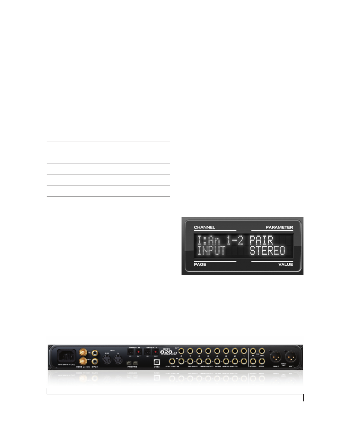
1Push the CHANNEL knob repeatedly until you
see “I:” (which stands for Input) in the CHANNEL
section of the LCD (Figure 3-7).
2Turn the CHANNEL KNOB until you see the
desired analog input or input pair. For example,
analog inputs 1-2 appear as “I:An 1-2”
(Figure 3-7), which means Input analog 1-2.
3From the factory, analog inputs are grouped in
stereo pairs (1-2, 3-4, etc.) If you need to split a pair
to deal with it as two individual mono inputs, turn
the PARAMETER knob until you see PAIR in the
parameter section of the LCD (Figure 3-7). Turn
the VALUE knob to choose MONO. Then turn the
CHANNEL knob again to select the desired input
you are adjusting.
Figure 3-7: The settings for analog inputs 1 and 2 (as a pair).
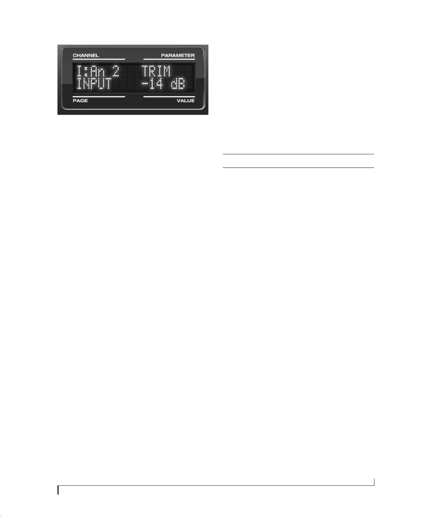
4After splitting the stereo pair, if necessary, turn
the PARAM knob until you see the TRIM
parameter in the LCD (Figure 3-8):
Input 48V Pad Trim
Condenser mic On As needed As needed
Dynamic mic Off As needed As needed
Guitar Off n/a As needed
-10 dB Line level via TRS Off n/a As needed
-10 dB Line level via XLR Off -20 dB +12dB
+4 dB line level (XLR only) Off -20 dB Zero
Figure 3-6: 828mk3 back panel
I N S T A L L I N G T H E 8 2 8 M K 3 H A R D W A R E
21
Figure 3-8: Setting the input trim for a TRS analog input pair.
5Turn the VALUE knob to adjust the trim.
Mic/guitar/instrument sends
Each front-panel XLR/TRS input has a
corresponding send on the rear panel (Figure 3-6).
The output from this send is the pre-amplified and
calibrated signal from the corresponding mic or
guitar input, which you can then route to any other
device, such as compressor, guitar amp, outboard
EQ, reverb unit, etc. Use any 828mk3 input (analog
or digital) as a return back into the 828mk3. From
there, you will be able to route the signal anywhere
in the system, such as to the computer and/or to
any CueMix FX mix bus.
XLR main outs
The XLR main outputs serve as independent
outputs. From the factory, the main out volume is
controlled by the MASTER VOL knob on the front
panel, although this knob can be programmed to
control any combination of outputs. For details, see
“The Monitor Group” on page 96. In a standard
studio configuration, the main outs are intended
for a pair of studio monitors, but they can also be
used as additional outputs for any purpose.
Optical
The 828mk3 rear panel provides two sets of ADAT
optical (“lightpipe”) connectors: Bank A and B
(Figure 3-6). Each bank provides an input and
output connector. All four connectors can operate
independently and offer two different optical
formats: ADAT optical or TOSLink (optical S/
PDIF). For example, you could connect 8-channel
ADAT optical input from your digital mixer and
stereo TOSLink output to an effects processor.
The 828mk3 supplies +12dB of digital trim (boost)
for each optical input, which can be adjusted from
CueMix FX (“Input trim” on page 80) or the front
panel (“The IN (inputs) menu” on page 47).
Below is a summary of optical formats:
Optical operation at 44.1 or 48 kHz
When configured for ADAT “lightpipe”, an optical
connector provides 8 channels at 44.1 and 48 kHz.
ADAT optical operation at 88.2 or 96 kHz
When configured for ADAT “lightpipe”, an optical
connector provides four channels at 88.2 or 96 kHz
(2x sample rates). When using the ADAT lightpipe
format at a 2x rate, be sure to choose either Type I
or Type II operation, as explained in “ADAT SMUX
Type” on page 46.
Using optical I/O to operate the 828mk3 as a
16-channel expander
When the 828mk3 is not connected directly to a
computer via FireWire, the sixteen optical output
channels can be programmed (via the CueMix FX
mixer) to mirror the incoming signal on any
combination of the 828mk3’s inputs. By
connecting the 828mk3 optical outputs to another
device, such as another ADAT-optical equipped
interface or a digital mixer, you add up to sixteen
additional inputs to your system (or eight inputs at
the 2x sample rates).
To learn how to program the 828mk3 when it is
operating as a stand-alone expander in this
fashion, see chapter 6, “Front Panel Operation”
(page 43).
Format 44.1 or 48 kHz 88.2 or 96 kHz
ADAT optical 8 channels 4 channels
TOSLink stereo stereo
I N S T A L L I N G T H E 8 2 8 M K 3 H A R D W A R E
22
Choosing a clock source for optical connections
When connecting an optical device, make sure that
its digital audio clock is phase-locked (in sync
with) the 828mk3, as explained in “Making sync
connections” on page 26. There are two ways to do
this:
1. Resolve the optical device to the 828mk3
2. Resolve the 828mk3 to the optical device
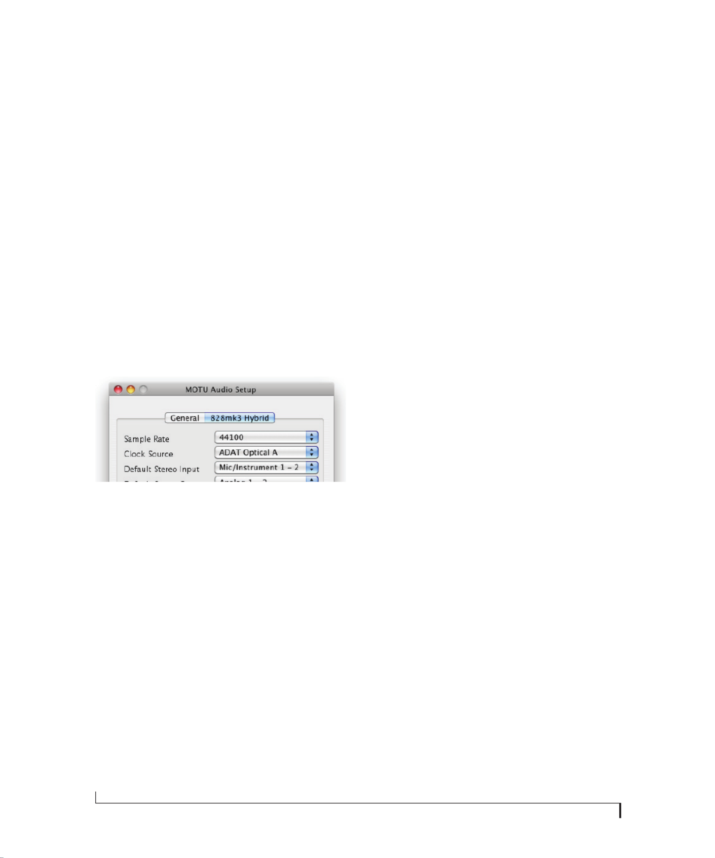
For 1), choose Internal (or any other clock source
except ADAT optical) as the clock source for the
828mk3 in MOTU Audio Setup.
For 2), choose either ADAT Optical A or ADAT
Optical B as the 828mk3’s clock source
(Figure 3-9). Be sure to choose the optical port that
the device is connected to.
Figure 3-9: Resolving the 828mk3 to an optical device.
For details about using the clock source setting and
the MOTU Audio Setup software in general, see
chapter 5, “MOTU Audio Setup” (page 37).
Using word clock to resolve optical devices
If the optical device you are connecting to the
828mk3 has word clock connectors on it, you can
use them to resolve the device to the 828mk3,
similar to the diagram shown in Figure 3-18 on
page 28 for S/PDIF devices with word clock. Also
see “Syncing word clock devices” on page 29.
S/PDIF
If you make a S/PDIF digital audio connection to
another device, be sure to review the digital audio
clocking issues, as explained in “Syncing S/PDIF
devices” on page 28.
The 828mk3 supplies +12dB of digital trim (boost)
for the S/PDIF input pair, which can be adjusted
from CueMix FX (“Input trim” on page 80) or the
front panel (“The IN (inputs) menu” on page 47).
I N S T A L L I N G T H E 8 2 8 M K 3 H A R D W A R E
23
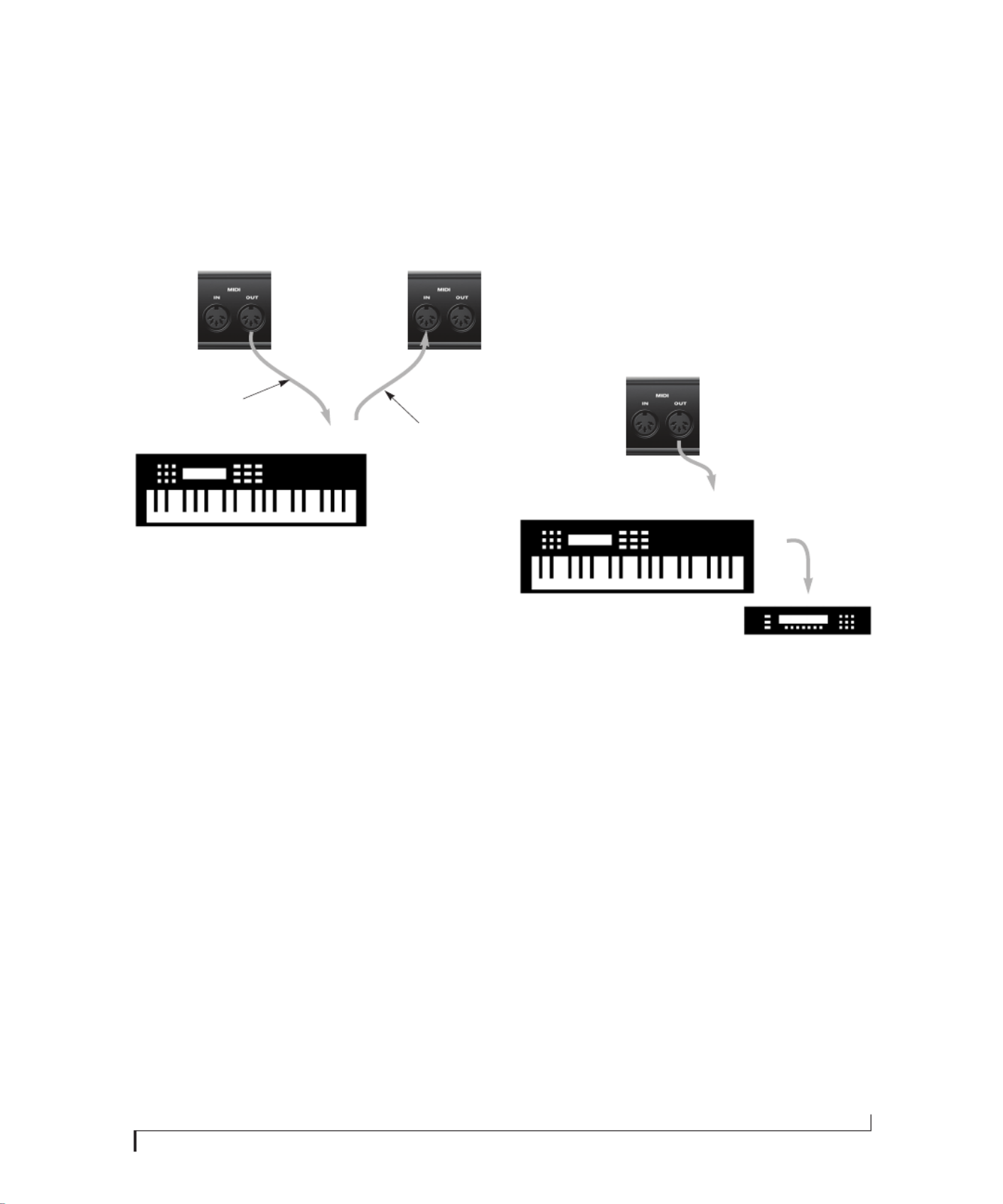
CONNECT MIDI GEAR
Connect your MIDI device’s MIDI IN jack to the
828mk3’s MIDI OUT jack (Connection A below).
Conversely, connect the MIDI device’s MIDI OUT
jack to the 8238mkII’s MIDI IN jack (Connection
B).
Figure 3-10: Connecting a MIDI device to the 828mk3.
One-way MIDI connections
MIDI devices that do not receive MIDI data, such
as a dedicated keyboard controller, guitar
controller, or drum pad, only need Connection B
shown in Figure 3-10. Similarly, devices that never
send data, such as a sound module, only need
Connection A. Make both connections for any
device that needs to both send and receive MIDI
data.
Connecting additional gear with MIDI THRUs
If you need to connect several pieces of MIDI gear,
run a MIDI cable from the MIDI THRU of a device
already connected to the 828mk3 to the MIDI IN
on the additional device as shown below in
Figure 3-11. The two devices then share the
828mk3’s MIDI OUT port. This means that they
share the same set of 16 MIDI channels, too, so try
to do this with devices that receive on only one
MIDI channel (such as effects modules) so their
receive channels don’t conflict with one another.
Figure 3-11: Connecting additional devices with MIDI THRU ports.
CONNECT A FOOT SWITCH
If you would like to use a foot switch with your
828mk3, connect it to the PUNCH IN/OUT jack.
See “Quick Reference: MOTU Audio Setup” on
page 7 for information about how to program the
foot switch to trigger any computer keystroke you
wish.
828mk3
rear panel
MIDI Device
MIDI
cables
MIDI
IN
MIDI
OUT
MIDI
OUT
MIDI
IN
Connection A
Connection B
MIDI IN
MIDI
cable
MIDI Device
MIDI
IN
MIDI
THRU
MIDI
OUT
828mk3
rear panel
I N S T A L L I N G T H E 8 2 8 M K 3 H A R D W A R E
24
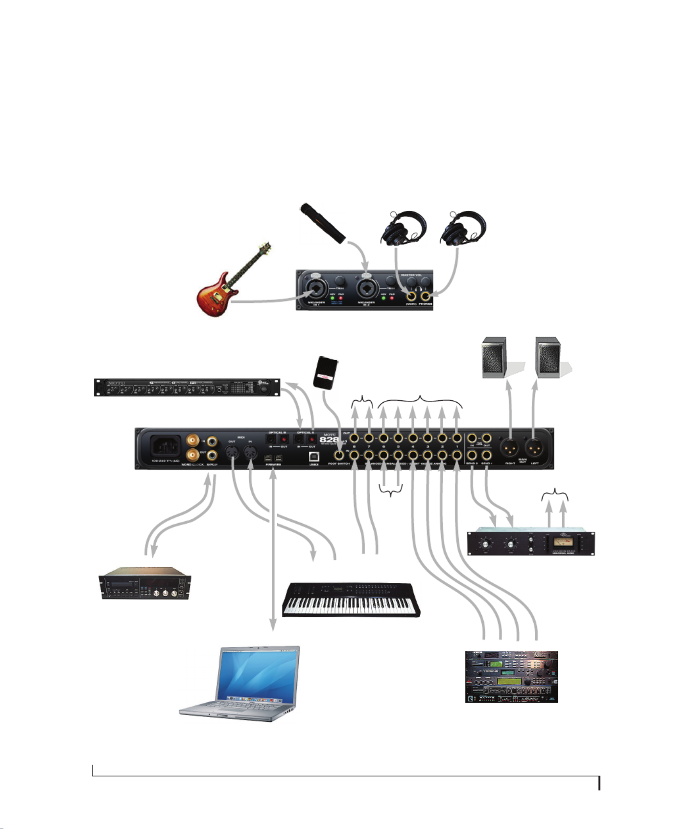
A TYPICAL 828MK3 SETUP
Here is a typical 828mk3 studio setup. This rig can
be operated without an external mixer. All mixing
and processing can be done in the computer with
audio software. During recording, you can use the
828mk3’s CueMix FX no-latency monitoring to
listen to what you are recording via the main outs,
headphone outs, or any other output pair. You can
control monitoring either from the front panel or
from the included CueMix FX software. The two
front-panel guitar/mic inputs can be routed to
outboard effects processors, such as a compressor,
EQ or reverb, via the rear panel sends.
Mac
S/PDIF
DAT deck
quarter-inch
analog outs
synthesizer
monitors
guitar
quarter-inch analog outs
synths, samplers, effects units, etc.
sends to
FX unit
(in rack
below)
Figure 3-12: A typical 828mk3 studio setup.
headphones
other outputs (stage
monitors, surround
monitors, etc.)
MIDI IN/OUT
foot
switch
828mk3
front panel
828mk3
back panel
Compressor, reverb or
other outboard gear
mic
FireWire or USB
MOTU 8pre and/or
other optical devices 8-channel
ADAT optical
headphones
send
returns
to send returns

I N S T A L L I N G T H E 8 2 8 M K 3 H A R D W A R E
25
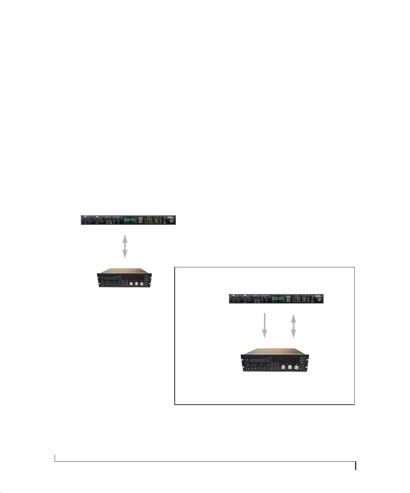
OPERATING THE 828mk3 AS A CONVERTER
As explained earlier in “Using optical I/O to
operate the 828mk3 as a 16-channel expander” on
page 21, the 828mk3 can serve as a multi-channel
analog-to-digital converter when disconnected
from the computer and instead connected to
another device equipped with an ADAT optical
input. For example, you could connect the 828mk3
optical output to the optical input on another
MOTU audio interface, such as a Traveler, 896mk3
or even another 828mk3. The 828mk3 then serves
as a multi-channel expander that adds additional
mic, analog TRS and digital inputs to the interface.
The benefit of connecting the 828mk3 in this
manner (instead of as another FireWire interface)
is that you can seamlessly integrate the 828mk3’s
inputs into the on-board no-latency CueMix
monitor mixing in the interface, since the 828mk3’s
inputs are fed into CueMix via the interface’s
optical inputs.
If the device to which you are connecting the
828mk3 supports 2x optical sample rates (88.2 or
96 kHz), you can also use both banks of connectors
as discussed in “ADAT optical operation at 88.2 or
96 kHz” on page 21.
Expander
828mk3
ADAT optical Out
Figure 3-13: Using the 828mk3 as an optical expander. In this example, it is connected to another 828mk3.
FireWire or USB
Base
828mk3
Mac
ADAT optical In

I N S T A L L I N G T H E 8 2 8 M K 3 H A R D W A R E
26
MAKING SYNC CONNECTIONS
If you connect devices digitally to the 828mk3, or if
you need to synchronize the 828mk3 with an
outside time reference such as SMPTE timecode,
you must pay careful attention to the synchroni-
zation connections and clock source issues
discussed in the next few sections.
Do you need to synchronize the 828mk3?
If you will be using only the 828mk3’s analog
inputs and outputs (and none of its digital I/O),
and you have no plans to synchronize your 828mk3
system to SMPTE timecode, you don’t need to
make any sync connections. You can skip this
section and proceed to chapter 4, “Installing the
828mk3 Software” (page 33). After you install the
828mk3 software, you’ll open MOTU Audio Setup
to confirm that the Clock Source setting is Internal
as shown below. For details, see chapter 5, “MOTU
Audio Setup” (page 37).
Figure 3-14: You can run the 828mk3 under its own internal clock
when it has no digital audio connections and you are not synchroniz-
ing the 828mk3 system to an external time reference such as
timecode.
Situations that require synchronization
There are three general cases in which you will
need to resolve the 828mk3 with other devices:
■Synchronizing the 828mk3 with other digital
audio devices so that their digital audio clocks are
phase-locked (as shown in Figure 3-15)
■Resolving the 828mk3 system to SMPTE
timecode from a video deck, analog multi-track,
etc.
■Both of the above
Synchronization is critical for clean digital I/O
Synchronization is critical in any audio system, but
it is especially important when you are transferring
audio between digital audio devices. Your success
in using the 828mk3’s digital I/O features depends
almost entirely on proper synchronization. The
following sections guide you through several
recommended scenarios.
Be sure to choose a digital audio clock master
When you transfer digital audio between two
devices, their audio clocks must be in phase with
one another — or phase-locked. Otherwise, you’ll
hear clicks, pops, and distortion in the audio — or
perhaps no audio at all.
Figure 3-15: When transferring audio, two devices must have phase-
locked audio clocks to prevent clicks, pops or other artifacts.
There are two ways to achieve phase lock: slave one
device to the other, or slave both devices to a third
master clock. If you have three or more digital
audio devices, you need to slave them all to a single
master audio clock.
Figure 3-16: To keep the 828mk3 phased-locked with other digital
audio devices connected to it, choose a clock master.
Also remember that audio phase lock can be
achieved independently of timecode (location).
For example, one device can be the timecode
master while another is the audio clock master. But
only one device can be the audio clock master. If
you set things up with this rule in mind, you’ll have
trouble-free audio transfers with the 828mk3.
Not phase-locked Phase-locked
Device A
Device B
Master
Slave
Master
Slave Slave

I N S T A L L I N G T H E 8 2 8 M K 3 H A R D W A R E
27
SYNCING TO SMPTE TIMECODE
The 828mk3 system can resolve directly to SMPTE
timecode. It can also generate timecode and word
clock, under its own clock or while slaving to
timecode. Therefore, the 828mk3 can act both as
an audio interface and as a digital audio
synchronizer to which you can slave other digital
audio devices. You can use the 828mk3 to slave
your audio software to SMPTE as well, via sample-
accurate sync (if your host software supports it) or
via MIDI Time Code (if your host software
supports it).
Other digital audio device
slaved to the 828mk3
Mac running AudioDesk,
Digital Performer or other sample-
accurate software, or host software
that supports MIDI Time Code sync
(such as Pro Tools or Logic).
Figure 3-17: Connections for synchronizing the 828mk3 directly to SMPTE timecode.
First, choose SMPTE as the clock source in AudioDesk, Digital
Performer, or MOTU Audio Setup. This setting can also be
made in the MOTU SMPTE Setup (shown below).
828mk3 interface
SMPTE
time code
source
Audio cable bearing LTC
(longitudinal timecode)
SMPTE IN
quarter-inch jack
FireWire or USB cable
Launch the MOTU SMPTE Setup to specify the timecode frame
rate and amount of freewheel. Also, confirm that the Clock
Source/Address is SMPTE/SMPTE. For details about the other
settings, see chapter 11, “MOTU SMPTE Setup” (page 119).
BNC
cable
Audio
cable
SMPTE
out
Word
Out
When lockup is
achieved, the
LOCK/TACH
light glows.
In AudioDesk or Digital Performer:
1. Choose Receive Sync from the Setup menu.
2. Choose the Sample-accurate option. (If this
option is grayed out, choose SMPTE as the
clock source setting first, as shown above.)
3. Make sure that Slave to External Sync mode
is enabled.
In Pro Tools:
1. Choose Peripherals from the Setup menu.
2. Click the Synchronization tab and choose the 828mk3 Sync Port from the MTC Reader Port menu.
Use this setup if you have:
✓A SMPTE timecode source, such as a multitrack tape deck.
✓An 828mk3 by itself, OR with another slaved device (such as a
digital mixer).
✓Host software that supports sample-accurate sync (such as
Digital Performer) or MIDI Time Code (such as Pro Tools).
This setup provides:
✓Continuous sync to SMPTE timecode.
✓Sub-frame timing accuracy.
✓Transport control from the SMPTE timecode source.
I N S T A L L I N G T H E 8 2 8 M K 3 H A R D W A R E
28
SYNCING S/PDIF DEVICES
S/PDIF devices will sync to the 828mk3 in one of
two ways:
■Via the S/PDIF connection itself
■Via word clock
S/PDIF devices with no word clock
If your S/PDIF device has no word clock sync
connectors, just connect it to the 828mk3 via the
S/PDIF connectors. When the device records
S/PDIF audio (from the 828mk3), it will simply
synchronize to the clock provided by the audio
input.
On the other hand, when you transfer audio from
the S/PDIF device into the 828mk3, you’ll have to
slave the 828mk3 to its S/PDIF input. If you have
other digital audio devices connected to the
828mk3, and they are not slaved directly to the
828mk3 itself, you may hear clicks and pops
resulting from their unsynchronized audio clock. If
so, just turn them off during the transfer.
S/PDIF devices with word clock
If your S/PDIF device has a Word Clock input, slave
the S/PDIF device to the 828mk3 via their word
clock connection. You can then freely transfer
audio between the 828mk3 and the S/PDIF device.
S/PDIF
S/PDIF
DAT deck
or other S/PDIF device
828mk3 828mk3
Clock Source setting =
Internal (when transferring from the
828mk3 to the S/PDIF device)
Figure 3-18: Two setups for synchronizing an S/PDIF device with the 828mk3. In the top diagram, sync is achieved via the S/PDIF connection
itself. In this case, you have to choose S/PDIF as the 828mk3’s clock source when recording from the S/PDIF device. If you don’t want to have to
worry about switching the Clock Source setting depending on the direction of the S/PDIF transfer, you can slave the S/PDIF device to word clock
from the 828mk3 or vice versa (not shown). The Word Clock connection maintains sync, regardless of the direction of the transfer.
828mk3
Clock Source setting =
S/PDIF (when transferring from
the S/PDIF device to the 828mk3)
SPDIF
SPDIF
DAT deck
or other SPDIF device
828mk3
Word Clock Out
Word Clock In
828mk3
Clock Source setting = Internal
With this setup, in the MOTU Audio Setup window, choose Internal, or any other
clock source setting except SPDIF. The DAT deck (or other SPDIF device) slaves to the
828mk3 via word clock for SPDIF transfers in both directions.

I N S T A L L I N G T H E 8 2 8 M K 3 H A R D W A R E
29
SYNCING WORD CLOCK DEVICES
The 828mk3 word clock connectors allow you to
synchronize it with a wide variety of other word
clock-equipped devices.
For standard word clock sync, you need to choose
an audio clock master (as explained in “Be sure to
choose a digital audio clock master” on page 26).
In the simplest case, you have two devices and one
is the word clock master and the other is the slave
as shown below in Figure 3-19 and Figure 3-20.
Figure 3-19: Slaving another digital audio device to the 828mk3 via
word clock. For the 828mk3 clock source, choose any source besides
word clock, as it is not advisable to chain word clock.
Figure 3-20: Slaving the 828mk3 to word clock. For the 828mk3 clock
source, choose ‘Word Clock In’.
Don’t chain word clock
If you have three or more digital audio devices that
you need to synchronize, avoid chaining their word
clock connections (OUT to IN, OUT to IN, etc.), as
this causes problems. Instead, use a dedicated
synchronizer like the Digital Timepiece or a word
clock distribution device of some kind.
Slaving to 2x and 1/2x word clock
All MOTU FireWire audio interfaces that support
96 kHz operation have the ability to slave to a word
clock signal running at either one half or one
quarter of their current clock rate. For example, the
828mk3 could be running at 96 kHz while slaving
to a 48 kHz word clock signal. Similarly, the
828mk3 could run at 88.2 kHz and slave to
44.1 kHz word clock.
Remember, the word clock signal must be one of
the following:
■the same as the 828mk3 clock
■half of the 828mk3 clock
Forcing a 1x word out rate
The 828mk3 can generate a word clock output
signal that either matches the current system clock
rate (any rate between 44.1 and 192kHz) or the
corresponding 1x rate. For example, if the 828mk3
is operating at 192kHz, you can choose to generate
a word out rate of 48kHz. For details on how to
make this word clock output setting, see “Word
Out” on page 42.
CONNECTING MULTIPLE MOTU FIREWIRE
INTERFACES
You can daisy-chain multiple MOTU FireWire
interfaces on a single FireWire bus, with the
restrictions described in the following sections.
Most computers have only one built-in FireWire
bus (even if it supplies multiple FireWire sockets).
Connect them as follows:
Master
Slave
Word clock OUT
Word clock IN
Other device
828mk3
Audio
clock
Master
Slave
MOTU Digital Timepiece universal synchronizer
Word clock OUT
Word clock IN
828mk3

I N S T A L L I N G T H E 8 2 8 M K 3 H A R D W A R E
30
Figure 3-21: Connecting multiple 828mk3 interfaces (or other MOTU
FireWire audio interfaces) to a computer.
Multiple interfaces cannot be bus-powered
Do not run the Traveler, UltraLite or other bus-
powered interfaces under bus power when
connecting them with other devices on the same
FireWire bus.
Multiple interfaces in MOTU Audio Setup
MOTU Audio Setup displays the settings for one
interface at a time. To view the settings for an
interface, click its tab as shown below in
Figure 3-22.
Figure 3-22: To view the settings for an interface, click its tab.
Synchronizing multiple interfaces
Mac OS X provides an advanced, exible driver
model that allows multiple Core Audio drivers to
be active at one time, accessed by multiple
applications simultaneously. For example, you can
run both FireWire and PCI audio interfaces at the
same time, accessing all of their inputs and outputs
from your host audio application — or even
multiple applications — simultaneously.
A by-product of this more exible model is that
multiple devices must be synchronized to one
another in order to remain resolved to each
another. Without synchronization, the audio
streams going to each interface might drift with
respect to one another. For example, the audio
tracks playing back through the 828mk3 might
drift out of sync with the audio tracks playing back
through your 2408mk3 PCI interface.
Synchronizing them to each other ensures that they
remain as tightly and continuously phase-locked as
if they were one unied interface.
There are two ways to synchronize the 828mk3
with other devices, as discussed in the following
sections: via the driver or via word clock.
Resolving to other Core audio drivers
The MOTU FireWire driver has the ability to
resolve to other Core Audio drivers. This allows the
828mk3, and other MOTU FireWire interfaces, to
resolve to other audio interfaces running simulta-
neously on the same computer, such as the Mac’s
built-in audio, a PCI-424 core system, or even
3rd-party interfaces, without the need for external
word clock connections between the devices.
Doing so ensures that audio tracks being played or
Mac
FireWire
FireWire
FireWire
FireWire
FireWire
FireWire
FireWire
FireWire
Word Clock Out
Word Clock In
Word Clock Out
Word Clock In
Word Clock Out
Word Clock In
For two
interfaces,
slave one to
the other.
You can probably
get away with
daisy-chaining
three interfaces,
although a word
clock distribu-
tion device is
recommended.
This is risky. A
word clock distri-
bution device is
highly recom-
mended.

I N S T A L L I N G T H E 8 2 8 M K 3 H A R D W A R E
31
recorded by your MOTU FireWire interface will
not drift apart from tracks on the other device
during long playback or recording passes.
To synchronize multiple devices via the MOTU
FireWire driver, choose one device (PCI, FireWire
or otherwise) as the master clock and then slave the
828mk3 and other FireWire devices to it. All
interfaces will remain resolved to each other via the
master interface.
Make the Clock Source settings for each interface
as follows:
■For the master interface, click its tab in the
FireWire Console and choose any clock source you
wish (except any of the slave interfaces, of course).
■For each slave interface, click its tab and choose
the master interface from the Clock Source menu, as
demonstrated below in Figure 3-23. This causes
the slave interfaces to resolve to the master
interface.
Figure 3-23: To resolve a MOTU FireWire interface to another Core
Audio device, choose the other device from the Clock Source menu in
the MOTU FireWire Audio Console. In this example, the Traveler will
slave to the 828mk3.
If you have multiple 828mk3s, choose one as the
master, and set its Clock Source to Internal. Then,
click the tab of the other 828mk3s and set their
Clock Source to the rst 828mk3.
Resolving to word clock
To resolve two 828mk3 FireWire interfaces with
each other via word clock, choose one as the word
clock master and then slave the second interface to
the rst, as shown in Figure 3-21 on page 30. For
three interfaces, you can probably get away with
daisy-chaining them via their word clock
connectors, but this may not always produce the
most reliable results. For three or more devices, a
word clock distribution device is highly
recommended. In this case, the distribution box is
the master, and all FireWire interfaces slave directly
to it (instead of to each other).
Connecting other MOTU FireWire interfaces
You can add an original MOTU 828 to the end of a
FireWire daisy chain (because the 828 has only one
FireWire port), or you can mix and match multiple
828’s with other MOTU FireWire interfaces using a
standard FireWire hub. You can also add 828mkIIs,
896HDs, Travelers and UltraLites, which have two
FireWire ports convenient for daisy-chaining.
Operating multiple FireWire interfaces at high
sample rates
Four MOTU FireWire interfaces can operate at
44.1 or 48kHz on a single FireWire bus, although
you may have to disable optical banks to conserve
FireWire bus bandwidth. At the 2x samples rates
(88.2 or 96kHz) and 4x sample rates (176.4 and
192kHz), you can operate no more than two
FireWire interfaces on a single FireWire bus.
Adding additional interfaces with a second
FireWire bus
Third-party FireWire bus expansion products in
the form of a cardbus (“PC card”) adapter or PCI
card allow you to add a second FireWire bus to
your computer. In may be possible to add
additional MOTU FireWire interfaces connected
to such a third-party product, depending on their
performance with your host computer.

I N S T A L L I N G T H E 8 2 8 M K 3 H A R D W A R E
32

CHAPTER
33
4Installing the 828mk3 Software
OVERVIEW
Software installation. . . . . . . . . . . . . . . . . . . . . . . . . . . . . . . . . 33
CueMix FX . . . . . . . . . . . . . . . . . . . . . . . . . . . . . . . . . . . . . . . . . . . 35
MOTU SMPTE Setup . . . . . . . . . . . . . . . . . . . . . . . . . . . . . . . . . 35
AudioDesk workstation software . . . . . . . . . . . . . . . . . . . . 35
SOFTWARE INSTALLATION
Install the 828mk3 Hybrid software as follows:
1 Insert the MOTU Audio Installer disc and
launch the installer.
2 Follow the directions that the installer gives you.
What does the installer do?
The installer checks the computer to make sure it
satises the minimum system requirements for
your MOTU interface. If so, the installer proceeds
with the OS X installation. Drivers are installed,
along with the MOTU Audio Setup, CueMix FX,
and several other applications, summarized in the
following table:
The 828mk3 CoreAudio driver
CoreAudio is a term that refers to the software
technology built into Mac OS X that provides all of
its standardized audio features. More specically,
we use CoreAudio to refer to Mac OS X’s standard
audio driver model. A CoreAudio driver allows the
828mk3 to establish audio input and output with
any Mac OS X CoreAudio-compatible software.
Once the 828mk3’s CoreAudio driver has been
successfully installed (by the installer), and you
have chosen it for use in your host audio software,
the 828mk3 will appear as a choice for audio inputs
and outputs in your software.
All MOTU audio hardware, including our PCI
systems and other FireWire and USB interfaces,
ships with CoreAudio drivers that allow them to
operate successfully with virtually all Mac OS X
audio software.
Software component Location Purpose For more information
MOTU FireWire Audio driver.kext /System/Library/
Extensions
Provides 828mk3 multi-channel audio input
and output with all Mac OS X audio software
“The 828mk3 CoreAudio
driver” on page 33
MOTU MIDI driver.kext /System/Library/
Extensions
Provides 828mk3 MIDI input and output for
all Mac OS X MIDI software
“CoreMIDI and Audio
MIDI Setup” on page 34
MOTU MIDI driver.plugin /System/Library/
Audio/MIDI Drivers
Provides 828mk3 MIDI input and output for
all Mac OS X MIDI software
“CoreMIDI and Audio
MIDI Setup” on page 34
MOTU Audio Setup Applications folder Provides access to all of the settings in the
828mk3 and other MOTU interfaces.
Required for 828mk3 operation.
chapter 5, “MOTU Audio
Setup” (page 37)
CueMix FX Applications folder Gives you complete control over the 828mk3’s
CueMix FX on-board mixer, which provides
no-latency monitoring, mixing and process-
ing of live inputs through your 828mk3.
chapter 10, “CueMix FX”
(page 73)
MOTU SMPTE Setup Applications folder Provides access to the 828mk3 system’s
SMPTE time code sync features.
chapter 11, “MOTU SMPTE
Setup” (page 119)
AudioDesk Applications/MOTU
AudioDesk
Provides complete multi-track recording,
mixing and processing. Optional.
AudioDesk User Guide
AudioDesk Demo Project Anywhere you want Provides a multi-track mix that you can open,
play, and mix in AudioDesk. Optional.
AudioDesk User Guide

I N S T A L L I N G T H E 8 2 8 M K 3 S O F T W A R E
34
CoreMIDI and Audio MIDI Setup
CoreMIDI is the “under-the-hood” portion of
Mac OS X that handles MIDI services for MIDI
hardware and software. CoreMIDI provides many
universal MIDI system management features,
including MIDI communication between your
828mk3 FireWire interface and all CoreMIDI
compatible software.
Audio MIDI Setup is a utility included with
Mac OS X that allows you to congure your
828mk3 interface for use with all CoreMIDI
compatible applications. Audio MIDI Setup
provides:
■A “virtual” studio on your Mac that graphically
represents your MIDI hardware setup and that is
shared by all CoreMIDI-compatible programs
■A simple, intuitive list of your MIDI devices
whenever you need it in any CoreMIDI-compatible
program
Launching Audio MIDI Setup
1 Make sure your 828mk3 interface is connected
and turned on.
2 Launch the Audio MIDI Setup utility.
This can usually be found in /Applications/
Utilities. If it has been moved, just search for Audio
MIDI Setup.
3 Conrm that the 828mk3 is present in the MIDI
Devices tab of Audio MIDI Setup.
If the 828mk3 does not appear, or if it is grayed out,
check your cable connections and click Rescan
MIDI.
Figure 4-1: The 828mk3 interface as it appears in the MIDI tab of
Audio MIDI Setup.
Connecting MIDI devices to the 828mk3
Once your 828mk3 interface appears in Audio
MIDI Setup, you are ready to add devices, indicate
how they are connected, and identify properties
they may have for particular purposes. This
information is shared with all CoreMIDI
compatible applications.
To add a device in Audio MIDI Setup:
1 Click Add Device.
Figure 4-2: Adding a MIDI device.
2 Drag on its input and output arrows to draw
connections to the 828mk3 that match its physical
connection.

I N S T A L L I N G T H E 8 2 8 M K 3 S O F T W A R E
35
Figure 4-3: Connecting devices to the 828mk3. In this example, a
controller keyboard is connected to the 828mk3’s MIDI IN, and a
sound module is connected to the 828mk3 MIDI OUT.
3Double-click the device to make settings, such
as input and output channels, that further describe
the device.
Figure 4-4: Device settings.
4Repeat the above steps for each MIDI device
connected to the interface.
5When you are finished, quit Audio MIDI Setup.
Your configuration is automatically saved as the
default configuration, and it is shared with all
CoreMIDI-compatible software.
CUEMIX FX
This program provides a mixing console that gives
you control over the 828mk3’s on-board mixing
and effects processing. For details, see chapter 10,
“CueMix FX” (page 73).
MOTU SMPTE SETUP
The MOTU SMPTE Setup software provides a
complete set of tools to resolve the 828mk3 to
SMPTE time code, and to generate SMPTE for
striping, regenerating or slaving other devices to
the computer. For details, see chapter 11, “MOTU
SMPTE Setup” (page 119).
AUDIODESK WORKSTATION SOFTWARE
AudioDesk is an advanced workstation software
package for the 828mk3 that lets you record, edit,
mix, process, bounce and master multi-track
digital audio recording projects. Advanced features
include real-time 32-bit effects processing, 24-bit
recording, and much more.
See the AudioDesk manual included with your
828mk3 system for details.
Figure 4-5: AudioDesk for Mac OS X.

I N S T A L L I N G T H E 8 2 8 M K 3 S O F T W A R E
36

CHAPTER
37
5MOTU Audio Setup
OVERVIEW
MOTU Audio Setup gives you access to basic
828mk3 hardware settings, such as sample rate,
clock source, optical format and more.
Accessing the 828mk3 settings . . . . . . . . . . . . . . . . . . . . . . 37
‘828mk3 Hybrid ’ Tab Settings . . . . . . . . . . . . . . . . . . . . . . . 38
Sample Rate . . . . . . . . . . . . . . . . . . . . . . . . . . . . . . . . . . . . . . . . . 38
Clock Source. . . . . . . . . . . . . . . . . . . . . . . . . . . . . . . . . . . . . . . . . 39
Default Stereo Input/Output. . . . . . . . . . . . . . . . . . . . . . . . . 40
Phones. . . . . . . . . . . . . . . . . . . . . . . . . . . . . . . . . . . . . . . . . . . . . . . 41
Optical input/output. . . . . . . . . . . . . . . . . . . . . . . . . . . . . . . . . 41
Main Outs Assign . . . . . . . . . . . . . . . . . . . . . . . . . . . . . . . . . . . . 41
Return Assign. . . . . . . . . . . . . . . . . . . . . . . . . . . . . . . . . . . . . . . . 41
Word Out . . . . . . . . . . . . . . . . . . . . . . . . . . . . . . . . . . . . . . . . . . . . 42
‘General’ Tab settings . . . . . . . . . . . . . . . . . . . . . . . . . . . . . . . . 42
Launch MOTU Audio Setup when hardware becomes
available . . . . . . . . . . . . . . . . . . . . . . . . . . . . . . . . . . . . . . . . . . . . . 42
Edit Channel Names . . . . . . . . . . . . . . . . . . . . . . . . . . . . . . . . . 42
Enable Pedal. . . . . . . . . . . . . . . . . . . . . . . . . . . . . . . . . . . . . . . . . 42
ACCESSING THE 828MK3 SETTINGS
There are several ways to access MOTU Audio
Setup settings:
■Click the MOTU Audio Setup icon in the dock
■Right-click on the MOTU Audio Setup dock
icon to open the menu shown below.
■From within AudioDesk™ or Digital
Performer™, choose Setup menu>Congure Audio
System>Congure Hardware Driver (Note: this
dialog only provides access to basic settings such as
sample rate and clock source. For access to all
settings, use one of the techniques above.)
■In Cubase or Nuendo, open the Device Setup
window, click VST Audio System and choose
MOTU 828mk3 Hybrid from the ASIO Driver
menu. Then click the MOTU 828mk3 Hybrid item
in the list and click the Control Panel button.
■From the front panel LCD as explained in
chapter 6, “Front Panel Operation” (page 43).

M O T U A U D I O S E T U P
38
828mk3 Hybrid tab settings
The 828mk3 Hybrid tab (Figure 5-1) provides
settings that apply to a specic 828mk3 interface. If
you have several 828mk3 (or other MOTU)
interfaces connected, you’ll see a separate tab for
each one.
General tab settings
The General tab provides settings that apply
globally to all connected MOTU interfaces.
‘828MK3 HYBRID ’ TAB SETTINGS
Sample Rate
Choose the desired Sample Rate for recording and
playback. The 828mk3 can operate at 44.1 (the
standard rate for compact disc audio), 48, 88.2, 96,
176.4 or 192 kHz. Make sure that all of the devices
connected digitally to the 828mk3 match the
828mk3’s sample rate. Also make sure that your
Digital Timepiece, MIDI Timepiece AV or other
digital audio synchronizer matches it as well. At the
4x sample rates (176.4 or 192kHz), all digital I/O
on the 828mk3 is disabled.
☛Mismatched sample rates cause distortion and
crackling. If you hear this sort of thing, check the
sample rate settings in your hardware and here in
MOTU Audio Setup.
Operation at 4x sample rates (176.4 or 192kHz)
At the 4x sample rates (176.4 or 192kHz),
operation of the 828mk3 is restricted, due to the
higher audio bandwidth demands, as follows:
■All digital I/O is disabled (there is no ADAT
optical, TOSLink or S/PDIF input/output).
■The 828mk3 provides 8 channels of analog input
and 8 channels of analog output, simultaneously.
Figure 5-1: MOTU Audio Setup gives you access to all of the settings in the 828mk3 hardware.

M O T U A U D I O S E T U P
39
■The stereo return bus, as described in “Return
Assign” on page 41, can only be assigned to one of
the four available analog output pairs.
■The headphone output can only be assigned to
one of the four available analog output pairs.
■The Main Outs can only be assigned to one of
the four available analog output pairs.
Clock Source
The Clock Source determines the digital audio
clock that the 828mk3 will use as its time base. For
a complete explanation of synchronization issues,
see “Making sync connections” on page 26. The
following sections briey discuss each clock source
setting.
Internal
Use the Internal setting when you want the 828mk3
to operate under its own digital audio clock. For
example, you may be in a situation where all you
are doing is playing tracks off hard disk in your
digital audio software on the computer. In a
situation like this, you most often don’t need to
reference an external clock of any kind.
Another example is transferring a mix to DAT. You
can operate the 828mk3 system on its internal
clock, and then slave the DAT deck to the 828mk3
via the S/PDIF connection (usually DAT decks
slave to their S/DIF input when you choose the
S/PDIF input as their record source) or via the
828mk3’s word clock output (if your DAT deck has
a word clock input).
If you would like help determining if this is the
proper clock setting for your situation, see
“Making sync connections” on page 26.
Word Clock In
The Word Clock In setting refers to the Word Clock
In BNC connector on the 828mk3 rear panel.
Choosing this setting allows the 828mk3 to slave to
an external word clock source, such as the word
clock output from a digital mixer or another
828mk3.
S/PDIF
The S/PDIF clock source setting refers to the
S/PDIF RCA input jack on the 828mk3. This
setting allows the 828mk3 to slave to another
S/PDIF device.
Use this setting whenever you are recording input
from a DAT deck or other S/PDIF device into the
828mk3. It is not necessary in the opposite
direction (when you are transferring from the
828mk3 to the DAT machine).
For further details about this setting, see “Syncing
S/PDIF devices” on page 28.
ADAT Optical A / B
The ADAT optical clock source settings (ADAT
Optical A and ADAT Optical B) refer to the clock
provided by the 828mk3’s two optical inputs, when
either one is connected to another optical device.
These two settings only appear in the Clock Source
menu when their corresponding optical bank input
is enabled and set to the ADAT Optical format, as
explained in “Optical input/output” on page 41.
This setting can be used to resolve the 828mk3
directly to the optical input connection. Most of
the time, you can set up a better operating scenario
that uses one of the other synchronization options.
However, there may be occasions when you have an
optical device that has no way of synchronizing
digitally to the 828mk3 or an external
synchronizer. In this case, the ADAT Optical clock
source setting lets you slave the 828mk3 to the
device itself via its digital input to the 828mk3.
This setting is also useful if you just need to make a
simple, click-free digital transfer between the
828mk3 and another device — where a time code

M O T U A U D I O S E T U P
40
reference and shared transport control are not
needed — without having to set up an elaborate
synchronization scenario.
For further details, see “Choosing a clock source
for optical connections” on page 22.
TOSLink A / B
The TOSLink clock source settings (TOSLink A and
TOSLink B) refer to the clock provided by the
828mk3’s two optical inputs, when either one is
connected to another optical device. These two
settings only appear in the Clock Source menu
with their corresponding optical bank input is
enabled and set to the TOSLink format, as
explained in “Optical input/output” on page 41.
The TOSLink clock source setting refers to the
clock provided an optical S/PDIF device connected
to the 828mk3’s optical input. This setting can be
used to slave the 828mk3 directly to the optical
input connection. Most of the time, you can set up
a better operating scenario that uses one of the
other synchronization options. However, there
may be occasions when you have an TOSLink-
compatible device that has no way of
synchronizing digitally to the 828mk3 or an
external synchronizer such as the Digital
Timepiece. In this case, the TOSLink clock source
setting lets you slave the 828mk3 to the other
device via the 828mk3’s optical input.
This setting is also useful if you just need to make a
simple, click-free digital transfer between the
828mk3 and another device — where a time code
reference and shared transport control are not
needed — without having to set up an elaborate
synchronization scenario.
For further details, see “Choosing a clock source
for optical connections” on page 22.
SMPTE
Choose this setting to resolve the 828mk3 directly
to SMPTE time code (LTC) being received via the
828mk3’s quarter-inch SMPTE input jack. For
details, see “Syncing to SMPTE timecode” on
page 27 and chapter 11, “MOTU SMPTE Setup”
(page 119).
Built-in Audio
Choose this setting to resolve the 828mk3 to your
Mac’s built-in audio. Doing so will ensure that
audio streams playing back from or recorded by
the 828mk3 will not drift apart from audio streams
simultaneously played or recorded by the Mac’s
built-in mic, speakers or audio output.
Other audio devices (drivers)
The MOTU FireWire Audio Driver has the ability
to resolve to other Core Audio drivers. Doing so
will ensure that audio streams playing back from or
recorded by the 828mk3 will not drift apart from
audio streams simultaneously played or recorded
by the other devices.
Default Stereo Input/Output
In the System Preferences window, Mac OS X lets
you choose third-party hardware such as the
828mk3 for your Mac sound input and output. The
system input and output can be used for alert
sounds and general audio I/O for applications like
iTunes, iMovie, etc.

M O T U A U D I O S E T U P
41
Figure 5-2: The Mac OS X sound preferences let you use the 828mk3
for general stereo audio input and output for your Mac.
The Default Stereo Input and Default Stereo Output
settings in MOTU Audio Setup (Figure 5-1 on
page 38) let you specify the stereo input and output
on the 828mk3 to be used when it is chosen as the
audio I/O device in the system preferences.
Phones
The Phones setting lets you choose what you will
hear from the headphone jack. Choose Main Outs
if you’d like the headphone output to match the
Main Outs. Choose Phones if you would like the
headphones to serve as their own independent
output, which you can access as an independent
output destination in your host audio software and
as an output destination for the eight on-board
CueMix FX mix busses.
Optical input/output
The Optical input and Optical output settings let
you choose between ADAT optical (‘lightpipe’) and
S/PDIF optical (‘TOSLink’) as the format for the
828mk3’s two banks of optical input and output
(Bank A and Bank B). Choose the format that
matches the device connected. If you are not using
the optical connections, it is recommended that
you turn them off (by choosing Disabled from the
menu) to reduce bandwidth and processing
overhead. Note that you can operate each optical
port independently. For example, you could use the
ADAT optical format on the Bank A input (with a
digital mixer, for example) and optical S/PDIF on
the Bank A output (with a DAT deck, for example).
Main Outs Assign
Choose Main Outs from the Main Outs Assign
menu to treat the Main Outs as their own
independent output pair. Choose any other output
pair to cause the Main Outs to mirror (duplicate)
the output pair you choose.
Return Assign
The Return Assign menu lets you choose any pair of
828mk3 audio outputs. The audio signal from this
output pair is then sent back to the computer via
the Stereo Return 1-2 bus. This stereo return bus
from the 828mk3 appears in your host software
alongside all other 828mk3 inputs, wherever your
host software lists them.
The 828mk3 stereo return bus can be used for a
variety of purposes. For example, you could use it
to send a nal mix being played through the
828mk3 back to the computer, where you could
record it for mastering or archiving purposes.
As another example, you could use the stereo
return bus to capture tracks played from your host
software, along with live inputs being routed
directly through the 828mk3 hardware via CueMix
FX (with or without CueMix effects processing on
the live inputs).

M O T U A U D I O S E T U P
42
Word Out
The Word Out menu appears when the 828mk3 is
operating at a 2x sample rate (88.2 or 96kHz) or 4x
sample rate (176.4 or 192kHz). This menu lets you
set the word clock output either to match the
current sample rate (System Clock) or force it to the
corresponding 1x rate (either 44.1 or 48kHz). For
example, if the 828mk3 were operating at
176.4kHz, choosing the Force 44.1/48kHz option
would produce word clock output at 44.1kHz.
‘GENERAL’ TAB SETTINGS
Launch MOTU Audio Setup when hardware
becomes available
Check this option if you would like the MOTU
Audio Setup icon to appear in the application dock
as soon as a MOTU interface is detected (switched
on, plugged in, etc.)
Edit Channel Names
Click the Edit Channel Names button to open the
Channel Names window (Figure 5-3). This
window lets you edit the names of the 828mk3
inputs and outputs, as they appear in your host
audio software. For example, when you click on a
menu that displays the 828mk3 inputs (or
outputs), you will see the names you specify in this
window (e.g. “vocal mic”, “lead guitar”, etc.),
instead of the default generic names (“Analog 1”,
“Analog 2”, etc.)
☛Not all Mac OS X audio software supports
channel names. If not, you’ll see generic port
names in your host audio software.
Figure 5-3: The Edit Channel Names window.
Figure 5-4: 828mk3 channel names as they appear in Digital
Performer’s Bundles window.
Enable Pedal
Check the Enable Pedal option if a foot switch is
connected to the 828mk3 and you would like to
trigger recording punch in/out (or other software
functions) with it. Use the Set buttons to determine
what keystroke is triggered by the pedal-up and
pedal-down positions. You can assign the pedal to
any two keystrokes you wish. (You are not
restricted to punch in/out.)

CHAPTER
43
6Front Panel Operation
OVERVIEW
The 828mk3 Hybrid offers complete front-panel
programming via six rotary encoders and a 2x16
backlit LCD display. All 828mk3 settings can be
accessed via these front-panel controls.
Mic/guitar inputs . . . . . . . . . . . . . . . . . . . . . . . . . . . . . . . . . . . . 43
Master vol and (MAIN) phone jack . . . . . . . . . . . . . . . . . . . 43
Phones. . . . . . . . . . . . . . . . . . . . . . . . . . . . . . . . . . . . . . . . . . . . . . . 44
Meters and status LEDs . . . . . . . . . . . . . . . . . . . . . . . . . . . . . . 44
Push-button rotary encoders . . . . . . . . . . . . . . . . . . . . . . . . 45
Multi-function LCD display . . . . . . . . . . . . . . . . . . . . . . . . . . 45
828mk3 SETUP menu. . . . . . . . . . . . . . . . . . . . . . . . . . . . . . . . 46
Audio menu . . . . . . . . . . . . . . . . . . . . . . . . . . . . . . . . . . . . . . . . . 46
CueMix menu. . . . . . . . . . . . . . . . . . . . . . . . . . . . . . . . . . . . . . . . 47
Inputs menu . . . . . . . . . . . . . . . . . . . . . . . . . . . . . . . . . . . . . . . . . 50
Outputs menu . . . . . . . . . . . . . . . . . . . . . . . . . . . . . . . . . . . . . . . 50
Mixes menu. . . . . . . . . . . . . . . . . . . . . . . . . . . . . . . . . . . . . . . . . . 51
Reverb menu . . . . . . . . . . . . . . . . . . . . . . . . . . . . . . . . . . . . . . . . 51
Stand-alone operation. . . . . . . . . . . . . . . . . . . . . . . . . . . . . . . 51
MIC/GUITAR INPUTS
The 828mk3 front panel mic/guitar inputs are
equipped with many features to handle a wide
variety of recording situations.
For information about connections and settings,
see “Mic/guitar inputs with preamps” on page 19
in the installation chapter.
For information about the many settings available
for the mic/guitar inputs, see:
■“The Inputs tab” on page 79
■“The channel settings section” on page 83
■“The Channel tab” on page 83
■“The EQ tab” on page 85
■“The Dynamics tab” on page 92
MASTER VOL AND (MAIN) PHONE JACK
The phone jack labeled (MAIN) (Figure 6-1) is a
standard quarter-inch stereo headphone jack. Its
output is hard-wired to mirror the XLR main outs
on the rear panel. From the factory, the MASTER
VOL knob above it controls the main outs and this
jack, but MASTER VOL can be programmed to
control any combination of outputs. See “The
Monitor Group” on page 96 for details. Push the
knob once to view the current volume setting in the
LCD display; push it again to mute the monitor
group; push a third time to return to the previous
volume. Note that if the Monitor Group is
programmed to not include the main outs, the
MASTER VOL knob will no longer control the
volume of the phone jack, either.
Figure 6-1: The 828mk3 front panel mic/guitar inputs and phone jacks.

F R O N T P A N E L O P E R A T I O N
44
PHONES
From the factory, the PHONES jack (Figure 6-1) is
a discrete output at 44.1/48 kHz, but it can mirror
any other output pair (digital or analog) or serve as
its own independent output. For example, at 88.2/
96 kHz, it defaults to mirroring the XLR main outs.
At 176.4/192 kHz, it defaults to mirroring analog
outputs 1-2.
As the primary phone jack, it has its own dedicated
volume knob.
As explained in the previous section, the LCD
provides detailed feedback as you turn the knob
(Figure 6-4). To view the current setting without
changing it, just push the knob (without turning
it).
If you would like the (MAIN) phone jack and the
PHONES jack to output the same signal, assign the
PHONES output to mirror the main outs. In this
configuration, both the MASTER VOL and the
PHONES volume knobs control the PHONES
volume.
METERS AND STATUS LEDS
The meters and LEDs (Figure 6-2) provide
complete status and metering information for all
828mk3 inputs and outputs.
Mic/guitar inputs meters with V-Limit™
compressor
The two ten-segment meters for the mic/guitar
inputs show input levels from -42 to -1 in the first
column of LEDs, plus an additional range in a
second column from zero to +12 dB (plus clip).
Both inputs are equipped with V-Limit™, a
hardware limiter. With the limiter turned off,
signals that hit zero or above will clip (a hard digital
clip). However, with V-Limit turned on, signals can
go as high as +12 dB above zero with no digital
clipping. If the signal then goes above +12 dB, it
will clip, even with V-Limit engaged. In either case,
the clip LED (above +12) will illuminate. For
further information about V-Limit, as well as
another feature called Soft Clip, see “Overload
protection (mic/guitar inputs only)” on page 84.
Figure 6-2: The 828mk3 front panel meters and LEDs.
S/PDIF
digital
input
meters
Analog output activity LEDs Optical bank and
MIDI I/O activity
Mic/guitar
preamp
inputs with
V-Limit™
Main
out
meters
Sample
rate
Time code
Lock/Tach
S/PDIF
output
activity
LEDs
Analog
input
meters

F R O N T P A N E L O P E R A T I O N
46
828MK3 SETUP MENU
To access the 828mk3 SETUP menu, push the
PARAM knob until you see 828mk3 SETUP
displayed in the LCD. This menu provides basic
features for managing the 828mk3 hardware. Turn
the PARAM knob to access each setting, explained
briefly below.
LCD Contrast
Turn the VALUE knob to adjust the LCD contrast.
Figure 6-5: In setup mode, the LCD displays a setup parameter in the
top row of the LCD and the current setting in the bottom row.
Save/Name Preset
An 828mk3 preset holds all current CueMix FX
mix settings (everything in the CUEMIX menu).
SETUP menu and AUDIO menu parameters are
not included. Turn the VALUE knob to move from
character to character in the preset name. Turn
PAGE to change the currently flashing letter. Once
you’ve named the preset, push VALUE to save it,
turn it again to choose the desired preset slot you
wish to save it to (1-16), and the push again to
confirm the save. To cancel the save operation at
any time by turning the PARAM knob.
Load Preset
Turn VALUE to choose the preset you wish to load
(1-16) and push VALUE to load it.
All Notes Off
The All Notes Off setting sends a MIDI All Notes Off
message, as well as a MIDI note-off message for
every note on every MIDI channel. This stops any
stuck notes that are currently playing. Push VALUE
to send the All Notes Off MIDI data.
Factory Defaults
Push VALUE to restore the 828mk3 hardware to its
factory default settings. Push VALUE again to
confirm, or turn PARAM to cancel.
AUDIO MENU
To access the AUDIO menu, push the PARAM
knob until you see AUDIO displayed in the LCD.
This menu provides basic settings such as sample
rate, clock source, optical bank format (ADAT
versus TOSLink), and so on. These settings have
corresponding settings in the MOTU Audio Setup
software, as shown below:
* If the 828mk3 is currently connected to a computer, this setting
cannot be changed from the front-panel LCD. It must be changed in
MOTU Audio Setup instead. Or, you can disconnect the 828mk3 from
the computer to change the Clock Source from the front panel.
ADAT SMUX Type
When the 828mk3 is operating at either 88.2 or
96 kHz, the AUDIO menu includes an item called
ADAT SMUX Type.
This setting lets you configure the optical ports for
ADAT format operation at the 2x sample rates only
(88.2 or 96 kHz).
There are two choices:
■Type I — for 2x optical connection to 3rd-party
SMUX-compatible hardware products
Audio menu item Where to find more information
Clock Source* “Clock Source” on page 39
Sample rate* “Sample Rate” on page 38
Phones Assign “Phones” on page 41
Main Out Assign “Main Outs Assign” on page 41
Return Assign “Return Assign” on page 41
Optical In/Out A/B* “Optical input/output” on page 41
ADAT SMUX Type See below. This menu item is only
available when the 828mk3 is operat-
ing at 88.2 or 96 kHz.
Word Clock Out “Word Out” on page 42

F R O N T P A N E L O P E R A T I O N
47
■Type II — for 2x optical connection to MOTU
products that are equipped with optical ports and
support 2x operation
Turn the VALUE knob to select an optical port and
push the knob to toggle between the Type I and
Type II setting.
CUEMIX MENU
To access the CUEMIX menu, push the PARAM
knob until you see CUEMIX displayed in the LCD.
This menu displays the settings for the 828mk3
CueMix FX mixer.
CueMix mixer basics
It is much easier to navigate the CUEMIX menu in
the LCD if you have a general understanding of the
CueMix FX mixer. We strongly recommend that
you review chapter 10, “CueMix FX” (page 73)
before learning the LCD, especially “CueMix FX
basic operation” on page 75.
CUEMIX menu organization
Mixer settings are divided into four sub-menus,
which correspond to the Inputs, Mixes, Outputs
and Reverb tabs in the CueMix FX software:
■IN (inputs)
■OUT (outputs)
■MIX (Mixes)
■REVERB (reverb processor)
Navigating the four main menus
To access the four main menus above, push the
CHANNEL knob repeatedly. Then turn the
CHANNEL knob to select the desired channel or
mix.
The IN (inputs) menu
Push the CHANNEL button repeatedly until you
see “I:” in the channel section of the LCD
(Figure 6-6). This is similar to accessing the Inputs
tab in CueMix FX console (“The Inputs tab” on
page 79).
Figure 6-6: The IN (inputs) menu.
Choosing a channel
Once you see the Inputs menu (Figure 6-6) in the
LCD, turn the CHANNEL knob to select the
desired input that you wish to edit. This is roughly
equivalent to specifying an input channel strip to
work with in the Inputs tab in CueMix FX software
(Figure 10-3 on page 79).
Choosing a setting to modify
Once you’ve selected an input channel, you can
access the various settings for that channel using
the PAGE knob and PARAMETER knobs.
Turn the PAGE knob to scroll through channel
settings such as individual bands of EQ, the
compressor, reverb sends, etc. Push the PAGE knob
to jump to the next “section” of parameters or to
jump back to the beginning of the list. This is
roughly the equivalent of moving through the
various channel controls in an individual input
“ I: ” Indicates
the IN (inputs)
menu.
The current
channel.
“Pages” are groups of
channel settings, such
as one band of EQ.
Access individual parameters
here, such as the frequency
setting for a band of EQ.
Change the value of the
current parameter here
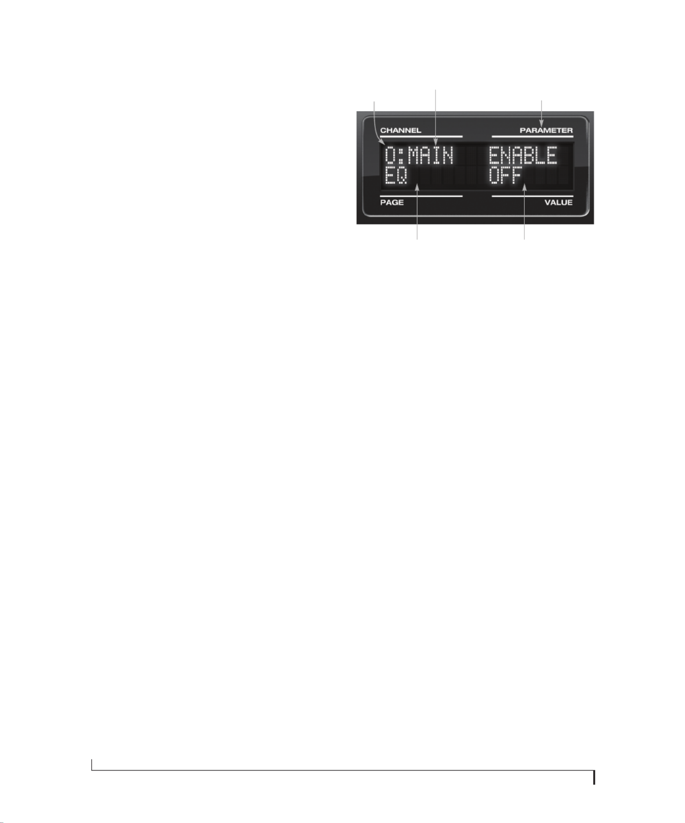
F R O N T P A N E L O P E R A T I O N
48
channel strip in CueMix FX (Figure 10-3 on
page 79), as well as the settings in the Channel tab
(Figure 10-8 on page 83).
Turn the PARAMETER knob to scroll through
individual parameters, such as the frequency for
the current band of EQ. This is roughly equivalent
to the parameters in the EQ tab (Figure 10-10 on
page 85), Dynamics tab (Figure 10-21 on page 92)
and Reverb tab (Figure 10-23 on page 95) in the
CueMix FX software.
Adjusting the value of a parameter
Turn the VALUE knob to adjust the value of the
current PARAMETER. Some parameters have
default values. If so, push the VALUE knob to cycle
through them.
Inactive items
If a menu item is inactive for some reason (perhaps
it doesn’t currently apply or it is disabled), it is
displayed in parentheses.
Copying and pasting
EQ, dynamics and Mix Assign settings allow you to
copy and paste settings between EQ bands and/or
channels. Push the VALUE knob to copy, scroll to
the other item and then push again to paste.
Summary of Inputs menu settings
For a summary of Inputs menu settings, see
“Inputs menu” on page 50.
The OUT (Outputs) menu
Push the CHANNEL button repeatedly until you
see “O:” in the channel section of the LCD
(Figure 6-7). This is similar to accessing the
Outputs tab in CueMix FX console (“The Outputs
tab” on page 81).
Figure 6-7: The OUT (outputs) menu.
Choosing a channel
Once you see the Outputs menu (Figure 6-7) in the
LCD, turn the CHANNEL knob to select the
desired output that you wish to edit. This is roughly
equivalent to specifying an output channel strip to
work with in the Outputs tab in CueMix FX
software (Figure 10-6 on page 82).
Working with outputs in the LCD
Once you’ve selected an output channel, you can
access the various settings for that channel using
the PAGE knob and PARAMETER knobs. The
knobs function the same as described for inputs in
“Choosing a setting to modify” on page 47 and
“Adjusting the value of a parameter” on page 48.
Summary of Output menu settings
For a summary of Inputs menu settings, see
“Outputs menu” on page 50.
“ O: ” Indicates
the OUT
(outputs) menu.
The current
channel.
“Pages” are groups of
channel settings, such
as one band of EQ.
Access individual parameters
here, such as the frequency
setting for a band of EQ.
Change the value of the
current parameter here
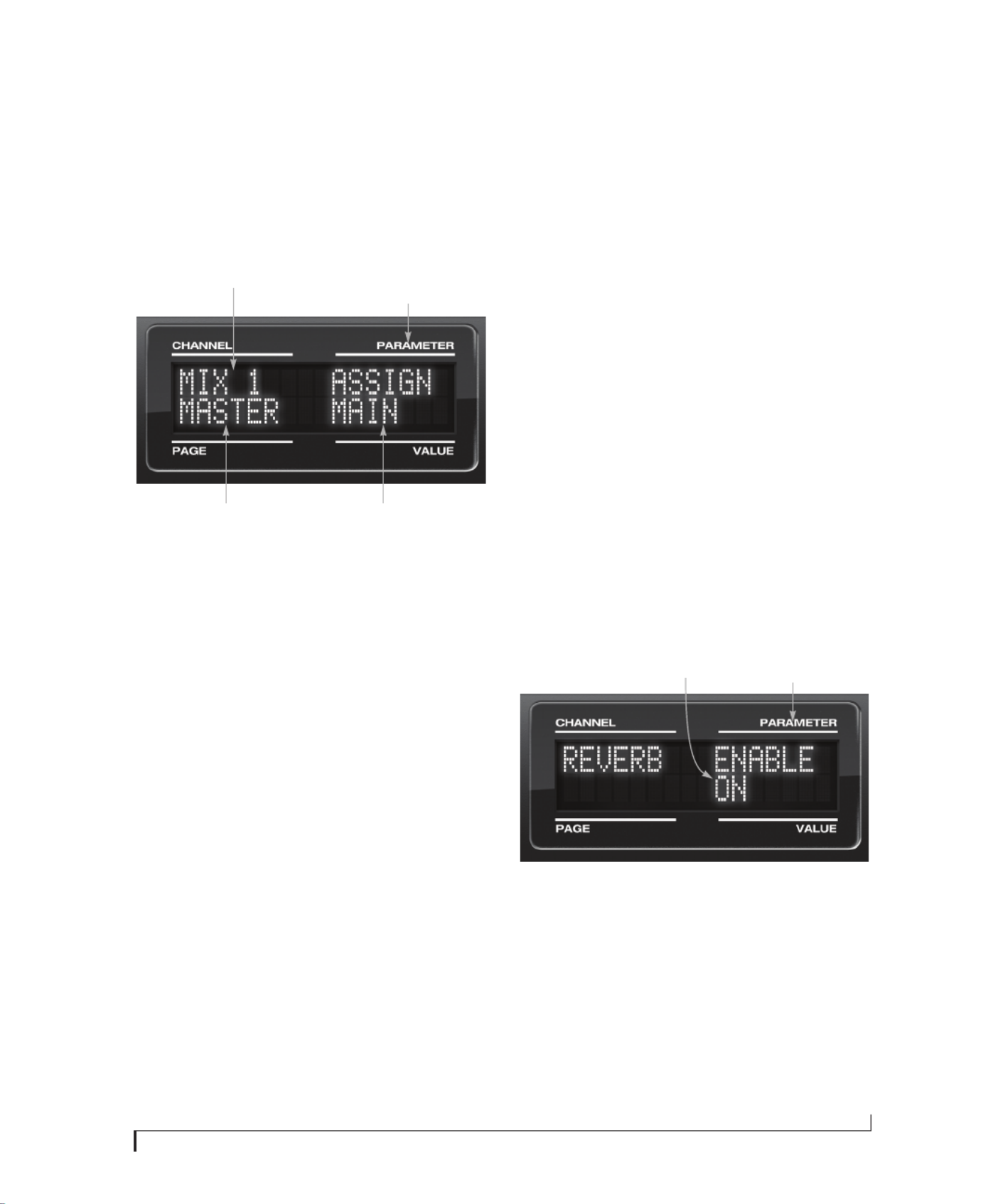
F R O N T P A N E L O P E R A T I O N
49
The MIX (Mixes) menu
Push the CHANNEL button repeatedly until you
see “MIX 1” (or “MIX 2”, etc.) in the channel
section of the LCD (Figure 6-8). This is similar to
accessing the Mixes tab in CueMix FX console
(“The Mixes tab” on page 77).
Figure 6-8: The MIX (Mixes) menu.
Choosing a mix bus
Once you see the MIX menu (Figure 6-8) in the
LCD, turn the CHANNEL knob to select the
desired mix that you wish to edit. This is roughly
equivalent to choosing a mix in the Mixes tab in
CueMix FX software (Figure 10-2 on page 77).
Working with mix busses in the LCD
Once you’ve selected a mix, you can access the
various settings for that mix using the PAGE knob
and PARAMETER knobs. The knobs function the
same as described for inputs in “Choosing a setting
to modify” on page 47 and “Adjusting the value of a
parameter” on page 48. The PAGE knob scrolls
through the following mix bus settings:
■MASTER — these are master fader settings,
such as the master fader output assignment, master
mute on/off, and the master fader volume. Access
them with the PARAMETER knob.
■REVERB — these are the reverb send and return
controls for the bus master fader. Access them with
the PARAMETER knob.
■Individual channels — once you scroll past
MASTER and REVERB, the PAGE knob then
scrolls through all available inputs for the mix bus.
Once you choose an input, access its channel
settings using the PARAM knob and VALUE knob.
Summary of Mix menu settings
For a summary of Mix menu settings, see “Mixes
menu” on page 51.
The REVERB menu
Push the CHANNEL button repeatedly until you
see “REVERB” in the channel section of the LCD
(Figure 6-9). This is similar to accessing the Reverb
tab in CueMix FX (“The Reverb tab” on page 95).
☛The REVERB processor is not available at
sample rates above 48 kHz. Therefore, when the
828mk3 is operating at 88.2 kHz or higher, the
REVER menu does not appear in the LCD.
Figure 6-9: The REVERB menu.
Working with reverb settings in the LCD
Once you’ve selected the REVERB menu, you can
access all settings using the PARAMETER and
VALUE knobs. The PAGE knob is not needed and
is therefore disabled when editing reverb settings.
Summary of Reverb menu settings
For a summary of Reverb menu settings, see
“Reverb menu” on page 51.
The current
mix bus.
Here, choose master fader
settings, reverb settings, and
individual input channels.
Access individual parameters
here, such as input channel
settings.
Change the value of the
current parameter here
Access individual
parameters here,
such as reverb time.
Change the value of
the current parame-
ter here.
F R O N T P A N E L O P E R A T I O N
50
INPUTS MENU OUTPUTS MENU
CHANNEL PAGE PARAM
INPUTS
mic 1-2
Analog 1-2
Analog 3-4
etc.
INPUT PAIR
PHASE
L-R/M-S (stereo or M/S)
SWAP
WIDTH
TRIM
LIMITER
LOOKAHEAD
SOFTCLIP
EQ
(global)
ENABLE
COPY
PASTE
RESET
HPF
(High-pass)
ENABLE
SLOPE
FREQ
LF
(Low w/shelf)
ENABLE
TYPE
FREQ
GAIN
WIDTH
LMF
(Low-mid)
ENABLE
TYPE
FREQ
GAIN
WIDTH
MF
(Mid)
ENABLE
TYPE
FREQ
GAIN
WIDTH
HMF
(High-mid)
ENABLE
TYPE
FREQ
GAIN
WIDTH
HF
(High w/shelf)
ENABLE
TYPE
FREQ
GAIN
WIDTH
LPF
(Low-pass)
ENABLE
SLOPE
FREQ
DYN
(Dynamics)
ENABLE
COPY
PASTE
RESET
COMP
(Compressor)
ENABLE
MODE
THRESH
RATIO
ATTACK
RELEASE
TRIM
LEVELER ENABLE
MODE
REDUCE
MAKEUP
REVERB SEND
SEND PAN (mono only)
Mic
only
CHANNEL PAGE PARAM
OUTPUTS
Main
Analog 1-2
Analog 3-4, etc.
EQ
(global)
ENABLE
COPY
PASTE
RESET
HPF
(High-pass)
ENABLE
SLOPE
FREQ
LF
(Low w/shelf)
ENABLE
TYPE
FREQ
GAIN
WIDTH
LMF
(Low-mid)
ENABLE
TYPE
FREQ
GAIN
WIDTH
MF
(Mid)
ENABLE
TYPE
FREQ
GAIN
WIDTH
HMF
(High-mid)
ENABLE
TYPE
FREQ
GAIN
WIDTH
HF
(High w/shelf)
ENABLE
TYPE
FREQ
GAIN
WIDTH
LPF
(Low-pass)
ENABLE
SLOPE
FREQ
DYN
(Dynamics)
ENABLE
COPY
PASTE
RESET
COMP
(Compressor)
ENABLE
MODE
THRESH
RATIO
ATTACK
RELEASE
TRIM
LEVELER ENABLE
MODE
REDUCE
MAKEUP
REVERB SEND
SEND PAN
MASTER MONITOR
TALKBACK
LSNBACK

F R O N T P A N E L O P E R A T I O N
51
MIXES MENU
REVERB MENU
STAND-ALONE OPERATION
All settings, including all mix settings and global
settings, are saved in the 828mk3’s memory, and
they remain in effect even when the 828mk3 is not
connected to a computer. This allows you to use the
828mk3 as a stand-alone 8-bus mixer. You can
make adjustments to any setting at any time from
the front panel.
CHANNEL PAGE PARAM
MIXES
Mix 1
Mix 2
etc.
MASTER ASSIGN
MUTE
FADER
COPY
PASTE
RESET
REVERB SEND
RETURN
MIC 1
MIC 2
(if mono)
MUTE
SOLO
(BAL/WID) - n/a
PAN
FADER
MIC 1-2
(if stereo)
MUTE
SOLO
BAL/WID
WIDTH
FADER
ANALOG 1
ANALOG 2
etc.
(if mono)
MUTE
SOLO
(BAL/WID) - n/a
PAN
FADER
ANALOG 3-4
ANALOG 5-6
etc.
(if stereo)
MUTE
SOLO
BAL/WID
BAL
FADER
SPDIF MUTE
SOLO
BAL/WID
BAL
FADER
ADAT A1-2
ADAT A3-4
etc.
MUTE
SOLO
BALD/WID
BAL
FADER
ADAT B1-2
ADAT B3-4
etc.
MUTE
SOLO
BALD/WID
BAL
FADER
CHANNEL PAGE PARAM
REVERB --- ENABLE
TIME
PREDELAY
WIDTH
CUT Hz
CUT dB
ROOM
REFSIZE
REF LEV
LO %
MID %
HI %
LO XOVR
HI XOVR
SPLIT

CHAPTER
53
7Digital Performer and AudioDesk
OVERVIEW
This chapter provides a brief overview of the basic
I/O and synchronization operations with the
828mk3 Hybrid hardware and Digital Performer
and AudioDesk.
AudioDesk is included with your 828mk3 system.
For complete information about all of AudioDesk’s
powerful workstation features, refer to the
AudioDesk User Guide included with your 828mk3
system.
Digital Performer, MOTU’s state-of-the-art digital
audio workstation software, is available separately;
for details about upgrading from AudioDesk to
Digital Performer, talk to your authorized MOTU
dealer or visit MOTU.com.
Setting up your system . . . . . . . . . . . . . . . . . . . . . . . . . . . . . . 53
828mk3 settings . . . . . . . . . . . . . . . . . . . . . . . . . . . . . . . . . . . . . 53
Working with 828mk3 inputs and outputs . . . . . . . . . . 55
24-bit operation . . . . . . . . . . . . . . . . . . . . . . . . . . . . . . . . . . . . . 55
Processing live inputs with host plug-ins . . . . . . . . . . . . 56
Working with CueMix FX mixing and effects. . . . . . . . . 56
MIDI input and output . . . . . . . . . . . . . . . . . . . . . . . . . . . . . . . 56
MIDI sequencing. . . . . . . . . . . . . . . . . . . . . . . . . . . . . . . . . . . . . 56
Synchronization . . . . . . . . . . . . . . . . . . . . . . . . . . . . . . . . . . . . . 56
Using a foot switch . . . . . . . . . . . . . . . . . . . . . . . . . . . . . . . . . . 57
Exchanging project files . . . . . . . . . . . . . . . . . . . . . . . . . . . . . 57
SETTING UP YOUR SYSTEM
As described in chapter 4, “Installing the 828mk3
Software” (page 33), the MOTU software installers
will properly install and update everything for you.
If you are using a MIDI Timepiece AV or Digital
Timepiece for synchronization, be sure they are
present in Audio MIDI setup.
828MK3 SETTINGS
Choose the 828mk3 as your audio input output
device by choosing Configure Audio System>
Configure Hardware Driver from the Setup menu.
This window shows some of the 828mk3 settings,
such as sample rate and clock source, but to access
all of the 828mk3 settings, open MOTU Audio
Setup, as shown in Figure 5-1 on page 38.
For complete details about the 828mk3 settings, see
chapter 5, “MOTU Audio Setup” (page 37). The
following sections provide a brief explanation of
each 828mk3 setting for use with Digital Performer
and AudioDesk.

D I G I T A L P E R F O R M E R A N D A U D I O D E S K
54
Figure 7-1: Choose Setup menu> Configure Audio System> Configure
Hardware Driver to open the dialog shown above and access the
828mk3 Hybrid CoreAudio driver. To access the rest of the 828mk3
settings, open MOTU Audio Setup.
Sample rate
Choose the desired sample rate for the 828mk3
system and your project le. Newly recorded audio
in your project will have this sample rate. Imported
audio or soundbites in existing les that do not
match this sample rate will be displayed in the
Soundbites window with a red ‘X’ on their move
handles to indicate that they cannot be played.
Clock Source
This setting is very important because it
determines which audio clock the 828mk3 will
follow.
If you do not have any digital audio connections to
your 828mk3 (you are using the analog inputs and
outputs only), and you will not be slaving to
external SMPTE time code, choose Internal.
If you have digital audio devices connected to the
828mk3, or if you are not sure about the clock
source of your setup, be sure to read “Choosing a
clock source for optical connections” on page 22
and “Clock Source” on page 39.
If you are slaving to SMPTE time code via the
828mk3 itself, choose SMPTE and follow the
directions in “Syncing to SMPTE timecode” on
page 27.
Buffer Size
The Buffer Size setting can be used to reduce the
delay — or monitoring latency — that you hear
when live audio is patched through Digital
Performer. For example, you might have MIDI
instruments, samplers, microphones, and so on
connected to the analog inputs of the 828mk3. If
so, you will often be mixing their live input with
audio material recorded in Digital Performer. See
chapter 9, “Reducing Monitoring Latency”
(page 67) for complete details.
Phones
This 828mk3 setting lets you choose what you’ll
hear from the headphone jack. For example, if you
choose Main Out 1-2, the headphones will
duplicate the main outs. Or you can choose any
other output pair. If you choose Phones 1-2, this
setting makes the headphone jack serve as its own
independent output pair. As a result, you’ll see
Phones 1-2 as an additional audio destination in
audio output menus in Digital Performer and

D I G I T A L P E R F O R M E R A N D A U D I O D E S K
56
PROCESSING LIVE INPUTS WITH HOST
PLUG-INS
If you patch a live input (such as MIDI synthesizer)
through a plug-in effect in Digital Performer or
AudioDesk, you might hear a slight delay. There are
several ways to reduce this delay. For details, see
chapter 9, “Reducing Monitoring Latency”
(page 67).
WORKING WITH CUEMIX FX MIXING AND
EFFECTS
The 828mk3 provides powerful external mixing,
EQ, compression, and reverb, which you can
operate hand-in-hand with the complete mixing
environment of Digital Performer or AudioDesk.
For example, the 828mk3 can serve as a monitor
mixer routing channels to musicians, or it can
serve as an integrated extension of your Digital
Performer mixing environment. If you program an
828mk3 mixing and processing conguration that
goes hand in hand with your DP project, be sure to
use the le save features in CueMix FX to save the
828mk3 settings as a le in your DP project folder
for instant recall of all settings. See chapter 10,
“CueMix FX” (page 73) for complete details.
MIDI INPUT AND OUTPUT
Once you’ve followed the procedure for enabling
the 828mk3’s MIDI features as explained in
“Software installation” on page 33, the 828mk3
MIDI ports will appear as an input source and
output destination in MIDI I/O menus in Digital
Performer and AudioDesk.
MIDI SEQUENCING
AudioDesk can play audio as a background
application, allowing you to run a sequencer at the
same time in the foreground. However, there is no
way to continuously synchronize — or resolve — a
sequencer with AudioDesk, so the two programs
will eventually drift out of sync, even if you manage
to start them at the same time.
If you’d like to do integrated MIDI sequencing,
your best bet is Digital Performer, which offers all
of the same features as AudioDesk, along with
powerful, state-of-the-art MIDI sequencing. For
details about upgrading from AudioDesk to Digital
Performer, talk to your authorized MOTU dealer
or visit MOTU.com.
SYNCHRONIZATION
As you read through the following sections to
decide what form of synchronization you might
need with other devices in your studio, be sure to
consult “Making sync connections” on page 26 for
the proper hardware connections. Use the
synchronization diagrams to be clear about how
you will be synchronizing Digital Performer and
the 828mk3 to the other components of your
system.
Synchronizing digital audio connections
If you have devices connected to the 828mk3
digital inputs (optical or RCA S/PDIF), you need to
be concerned with the synchronization of the
828mk3’s digital audio clock with other devices
connected to it digitally (if any). For example, if
you have a digital mixer connected to the 828mk3
via an ADAT optical light pipe cable, you need to
make sure that their audio clocks are phase-locked.
For details, see “Choosing a clock source for optical
connections” on page 22 and “Making sync
connections” on page 26. If you don’t have any
digital audio devices connected to the 828mk3,
digital audio phase-lock does not apply to you.
Resolving directly to time code
If you need to slave the 828mk3 and Digital
Performer or AudioDesk to SMPTE time code, you
can do so with or without a dedicated
synchronizer.
To resolve your 828mk3 directly to SMPTE time
code with no additional synchronization devices,
use the setup shown in “Syncing to SMPTE
timecode” on page 27.

D I G I T A L P E R F O R M E R A N D A U D I O D E S K
57
USING A FOOT SWITCH
Use a foot switch connected to the 828mk3 to
trigger recording punch-in and punch-out, or any
other feature in Digital Performer or AudioDesk
that is assigned to a keyboard shortcut. By default,
the foot switch triggers the 3 key on the keyboard
number pad (which toggles the record button in
Digital Performer and AudioDesk.) To trigger a
different set of keystrokes with the foot switch, visit
the MOTU Audio Setup. (See “Enable Pedal” on
page 42.)
EXCHANGING PROJECT FILES
Digital Performer and AudioDesk can exchange
project les. To open an AudioDesk project in
Digital Performer, open it in same way you would a
DP project le — no conversion is required
beforehand in AudioDesk.
To open a Digital Performer project in AudioDesk,
use DP’s File menu > Save As command and choose
the “AudioDesk 2.0” as the project le format. Then
open the resulting AudioDesk 2.0 project le in
AudioDesk.

D I G I T A L P E R F O R M E R A N D A U D I O D E S K
58

CHAPTER
59
8Other Mac OS X Audio Software
OVERVIEW
The 828mk3 Hybrid provides multichannel audio
and MIDI input and output for all Mac OS X audio
applications, including Apple’s Logic Pro, Logic
Express, SoundTrack Pro and GarageBand. Other
third-party software applications are also
supported, such as Ableton Live, Propellerhead
Reason, Steinberg Cubase and others.
Installing the 828mk3 Mac OS X drivers . . . . . . . . . . . . . 59
Run MOTU Audio Setup . . . . . . . . . . . . . . . . . . . . . . . . . . . . . 59
Choosing the MOTU Core Audio driver . . . . . . . . . . . . . . 60
Working with 828mk3 inputs and outputs . . . . . . . . . . 63
Audio input and output names . . . . . . . . . . . . . . . . . . . . . . 63
Number of channels . . . . . . . . . . . . . . . . . . . . . . . . . . . . . . . . . 65
MIDI input and output . . . . . . . . . . . . . . . . . . . . . . . . . . . . . . . 65
Processing live inputs with host plug-ins . . . . . . . . . . . . 65
Working with CueMix FX mixing and effects. . . . . . . . . 65
Synchronization . . . . . . . . . . . . . . . . . . . . . . . . . . . . . . . . . . . . . 65
Using a foot switch . . . . . . . . . . . . . . . . . . . . . . . . . . . . . . . . . . 66
24-bit operation . . . . . . . . . . . . . . . . . . . . . . . . . . . . . . . . . . . . . 66
INSTALLING THE 828MK3 MAC OS X
DRIVERS
To install the 828mk3’s Mac OS X audio and MIDI
drivers, just run the MOTU Audio installer as
detailed in chapter 4, “Installing the 828mk3
Software” (page 33).
RUN MOTU AUDIO SETUP
Before you run your host audio software, launch
MOTU Audio Setup to congure your 828mk3
hardware. MOTU Audio Setup lets you congure
your audio interface, and it lets you enable the
desired inputs and outputs. Only enabled inputs
and outputs will be available to your host audio
software, so this is an important step. For complete
details see chapter 5, “MOTU Audio Setup”
(page 37).
Figure 8-1: MOTU Audio Setup.
For complete details about the 828mk3 settings, see
chapter 5, “MOTU Audio Setup” (page 37). The
following sections provide a brief explanation of
each 828mk3 setting for use with Logic and other
Mac OS X audio software.
Sample rate
Choose the desired overall sample rate for the
828mk3 system and your host audio software.
Newly recorded audio will have this sample rate.
Clock Source
This setting is very important because it
determines which audio clock the 828mk3 will
follow.
If you do not have any digital audio connections to
your 828mk3 (you are using the analog inputs and
outputs only), and you will not be slaving your host
software to external SMPTE time code, choose
Internal.
If you have digital audio devices connected to the
828mk3, or if you are not sure about the clock
source of your setup, be sure to read “Making sync
connections” on page 26 and “Clock Source” on
page 39.

O T H E R M A C O S X A U D I O S O F T W A R E
61
Figure 8-2: Enabling the 828mk3 Hybrid in Pro Tools
Logic Pro and Logic Express
In Logic Pro and Logic Express, go to the
Preferences window, click the Audio tab, click the
Drivers tab and click the Core Audio tab as shown
in Figure 8-3. Choose the MOTU 828mk3 Hybrid
from the Driver menu. For information about the
I/O Buffer Size setting, see “Adjusting the audio I/O
buffer” on page 69.
Figure 8-3: Enabling the 828mk3 Hybrid in Logic
Soundtrack Pro
In Soundtrack Pro, access the preferences window,
click the Recording tab and choose MOTU 828mk3
Hybrid from the Input and Monitor menu as shown
below in Figure 8-4.
Figure 8-4: Enabling the 828mk3 Hybrid in Soundtrack Pro.
Garage Band
In Garage Band, go to the Audio/MIDI preferences
and choose MOTU 828mk3 Hybrid from the Audio
Output and Audio Input menus as shown below in
Figure 8-5. For information about the Optimize for
setting, see “Adjusting the audio I/O buffer” on
page 69.
Figure 8-5: Enabling the 828mk3 Hybrid in Garage Band.

O T H E R M A C O S X A U D I O S O F T W A R E
62
Cubase and Nuendo
In Cubase or Nuendo, go to the Devices menu and
choose Device Setup. Click the VST Audio System
item in the Devices list and choose MOTU 828mk3
Hybrid from the Master ASIO Driver menu as
shown below in Figure 8-6. Activate the inputs and
outputs within Cubase or Nuendo as usual. For
information about the Audio Buffer Size setting, see
“Adjusting the audio I/O buffer” on page 69.
Figure 8-6: Enabling the 828mk3 Hybrid audio driver in Cubase.
Live
In Ableton Live, access the preferences window and
click the Audio tab. Choose CoreAudio from the
Driver Type menu. Choose the MOTU 828mk3
from the Input Audio Device and Output Audio
Device menus as shown below in Figure 8-7. For
information about the Buffer Size setting, see
“Adjusting the audio I/O buffer” on page 69.
Figure 8-7: Enabling the 828mk3 Hybrid in Live.

O T H E R M A C O S X A U D I O S O F T W A R E
63
Reason and Record
In Propellerhead Reason or Record, go to the
Preferences window, choose Audio preferences
from the menu and choose MOTU 828mk3 Hybrid
from the Audio Output menu as shown below in
Figure 8-8. For information about the Buffer Size
setting, see “Adjusting the audio I/O buffer” on
page 69.
Figure 8-8: Enabling the 828mk3 Hybrid in Reason and Record.
Reaper
In Cockos Reaper, access the Preferences and click
Devices under the Audio preferences. Choose
MOTU 828mk3 Hybrid from the Audio Device
menu.
Figure 8-9: Enabling the 828mk3 Hybrid in Reaper.
Other audio software
For other audio applications, the procedure is
similar to that shown above. Consult your owner’s
manual for further information.
WORKING WITH 828MK3 INPUTS AND
OUTPUTS
Once you’ve enabled the 828mk3’s Core Audio
driver, 828mk3 audio inputs and outputs will
appear in your host software wherever audio inputs
and outputs are listed. If you don’t see the optical
inputs and/or outputs, check MOTU Audio Setup
to make sure they are turned on. If you don’t plan
to use either optical bank, turn it off to conserve
computer bandwidth.
AUDIO INPUT AND OUTPUT NAMES
The 828mk3 Core Audio driver supplies text string
labels for its inputs and outputs to clearly identify
each one, but some applications do not display
these labels.
The following sections show how you can identify
each input and output in a numbered list like this.

O T H E R M A C O S X A U D I O S O F T W A R E
64
Inputs at 1x sample rates
Inputs are always listed in the same order as
follows, when operating the 828mk3 at 1x sample
rates (44.1 or 48 kHz):
Inputs at 2x sample rates
When operating the 828mk3 at a 2x sample rate
(88.2 or 96 kHz), inputs are listed as follows:
Inputs at 4x sample rates
When operating the 828mk3 at a 4x sample rate
(176.4 or 192 kHz), inputs are listed as follows:
Outputs at 1x sample rates
Outputs are always listed in the same order as
follows, when operating the 828mk3 at 1x sample
rates (44.1 or 48 kHz):
Input
Channels List position Comment
Mic-Guitar 2 1-2 -
Analog 8 3-10 -
Reverb
return
2 11-12 See “Reverb return”
on page 60.
Stereo
return
2 13-14 See “Return Assign”
on page 60.
SPDIF 2 15-16 -
Optical A 8 ADAT
2 TOSLink
17-24
17-18
-
Optical B 8 ADAT
2 TOSLink
25-32
19-20
These starting chan-
nel numbers assume
that optical A is
operating with the
same format.
Input
88.2 / 96 kHz Channels List position Comment
Mic-Guitar 2 1-2 -
Analog 8 3-10 -
Reverb
return
not
available
not
available
not
available
Stereo
return
2 11-12 See “Return Assign”
on page 60.
SPDIF 2 13-14 -
Optical A 4 ADAT
2 TOSLink
15-18
15-16
-
Optical B 4 ADAT
2 TOSLink
19-22
17-18
These starting chan-
nel numbers assume
that optical A is
operating with the
same format.
Input
176.4 /192 kHz Channels List position Comment
Mic-Guitar 2 1-2 -
Analog 8 3-10 -
Reverb
return
not
available
not
available
not
available
Stereo return 2 11-12 See “Return
Assign” on page 60.
SPDIF not
available
not
available
not
available
Optical A not
available
not
available
not
available
Optical B not
available
not
available
not
available
Output
44.1 / 48 kHz Channels
List
position Comment
Analog 8 1-8 -
Main outs 2 9-10 If the main outs are
assigned to mirror another
output pair (such as the
analog 1-2), they won’t be
listed separately.
Phones 2 11-12 If the phones are assigned
to mirror another output
pair (such as the main
outs), they won’t be listed
separately.
SPDIF 2 13-14 If the phones are mirror-
ing, then subtract 2. If the
main outs are mirroring,
subtract another 2.
Optical A 8 ADAT
2 TOSLink
15-22
15-16
-
Optical B 8 ADAT
2 TOSLink
23-30
17-18
These channel number
ranges assume that optical
A is operating with the
same format.

O T H E R M A C O S X A U D I O S O F T W A R E
65
Outputs at 2x sample rates
When operating the 828mk3 at a 2x sample rate
(88.2 or 96 kHz), outputs are listed as follows:
Outputs at 4x sample rates
When operating the 828mk3 at a 4x sample rate
(176.4 or 192 kHz), outputs are listed as follows:
NUMBER OF CHANNELS
If your host audio software requires that you
specify the number of audio voices or channels you
will be using, be sure to choose enough channels to
cover the 28 inputs and 30 outputs provided by
your 828mk3 — although the number of channels
may depend on how your 828mk3 is congured.
MIDI INPUT AND OUTPUT
Once you’ve followed the procedure for enabling
the 828mk3’s MIDI features as explained in
“Software installation” on page 33, the 828mk3
MIDI ports will appear as an input source and
output destination in your host software’s MIDI I/
O menus.
PROCESSING LIVE INPUTS WITH HOST
PLUG-INS
If you patch a live input (such as a MIDI
synthesizer) through a plug-in effect in your host
software, you might hear a slight delay. There are
several ways to reduce this delay. For details, see
chapter 9, “Reducing Monitoring Latency”
(page 67).
WORKING WITH CUEMIX FX MIXING AND
EFFECTS
The 828mk3 provides powerful external mixing,
EQ, compression and reverb, which you can
operate hand-in-hand with your host’s mixing
environment. For example, the 828mk3 can serve
as a monitor mixer routing channels to musicians,
or it can serve as an integrated extension of your
host’s mixing environment. If you program an
828mk3 mixing and processing conguration that
goes hand in hand with your host project, be sure
to use the le save features in CueMix FX to save
the 828mk3 settings as a le in your host project
folder for instant recall of all settings. See
chapter 10, “CueMix FX” (page 73) for complete
details.
SYNCHRONIZATION
As you read through the following sections to
decide what form of synchronization you might
need with other devices in your studio, be sure to
consult “Making sync connections” on page 26 for
the proper hardware connections. Use the
synchronization diagrams to be clear about how
you will be synchronizing your audio software and
the 828mk3 to the other components of your
system.
Output
88.2/ 96 kHz Channels
List
position Comment
Analog 8 1-8 -
Main outs 2 9-10 If the main outs are
assigned to mirror
another output pair
(such as the analog
1-2), they won’t be
listed separately.
Phones Mirror only -- -
SPDIF 2 11-12 If the main outs are
mirroring, then sub-
tract 2.
Optical A 4 ADAT
2 TOSLink
13-16
13-14
-
Optical B 4 ADAT
2 TOSLink
17-20
15-16
These channel num-
ber ranges assume
that optical A is oper-
ating with the same
format.
Output
176.4/ 192 kHz Channels
List
position Comment
Analog 8 1-8 -
Main outs Mirror only -- -
Phones Mirror only -- -
SPDIF Not available -- -
Optical A Not available -- -
Optical B Not available -- -

O T H E R M A C O S X A U D I O S O F T W A R E
66
Synchronizing digital audio connections
If you have devices connected to the 828mk3
digital inputs (optical or RCA S/PDIF), you need to
be concerned with the synchronization of the
828mk3’s digital audio clock with other devices
connected to it digitally (if any). For example, if
you have a digital mixer connected to the 828mk3
via an ADAT optical light pipe cable, you need to
make sure that their audio clocks are phase-locked.
For details, see “Choosing a clock source for optical
connections” on page 22 and “Making sync
connections” on page 26. If you don’t have any
digital audio devices connected to the 828mk3,
digital audio phase-lock does not apply to you.
Resolving directly to time code
If your host audio software supports Core Audio’s
sample-accurate positioning protocol, or if it can
slave to MIDI Time Code, then it can resolve to the
828mk3’s built-in time code synchronization
feature. To resolve your 828mk3 directly to SMPTE
time code with no additional synchronization
devices, use the setup shown in “Syncing to
SMPTE timecode” on page 27.
USING A FOOT SWITCH
Use a foot switch connected to the 828mk3 to
trigger recording punch-in and punch-out, or any
other feature in your host audio software that is
assigned to a computer keystroke. By default, the
foot switch triggers the 3 key on the computer
keypad. To trigger a different set of keystrokes with
the foot switch, visit MOTU Audio Setup. (See
“Enable Pedal” on page 42.)
24-BIT OPERATION
Your 828mk3 hardware fully supports 24-bit
recording capabilities in any audio software that
supports it. Simply enable 24-bit operation as
instructed by the software. The 828mk3 always
supplies the software a 24-bit data stream, and
when you enable 24-bit operation, it simply uses all
24-bits supplied by the 828mk3 hardware.
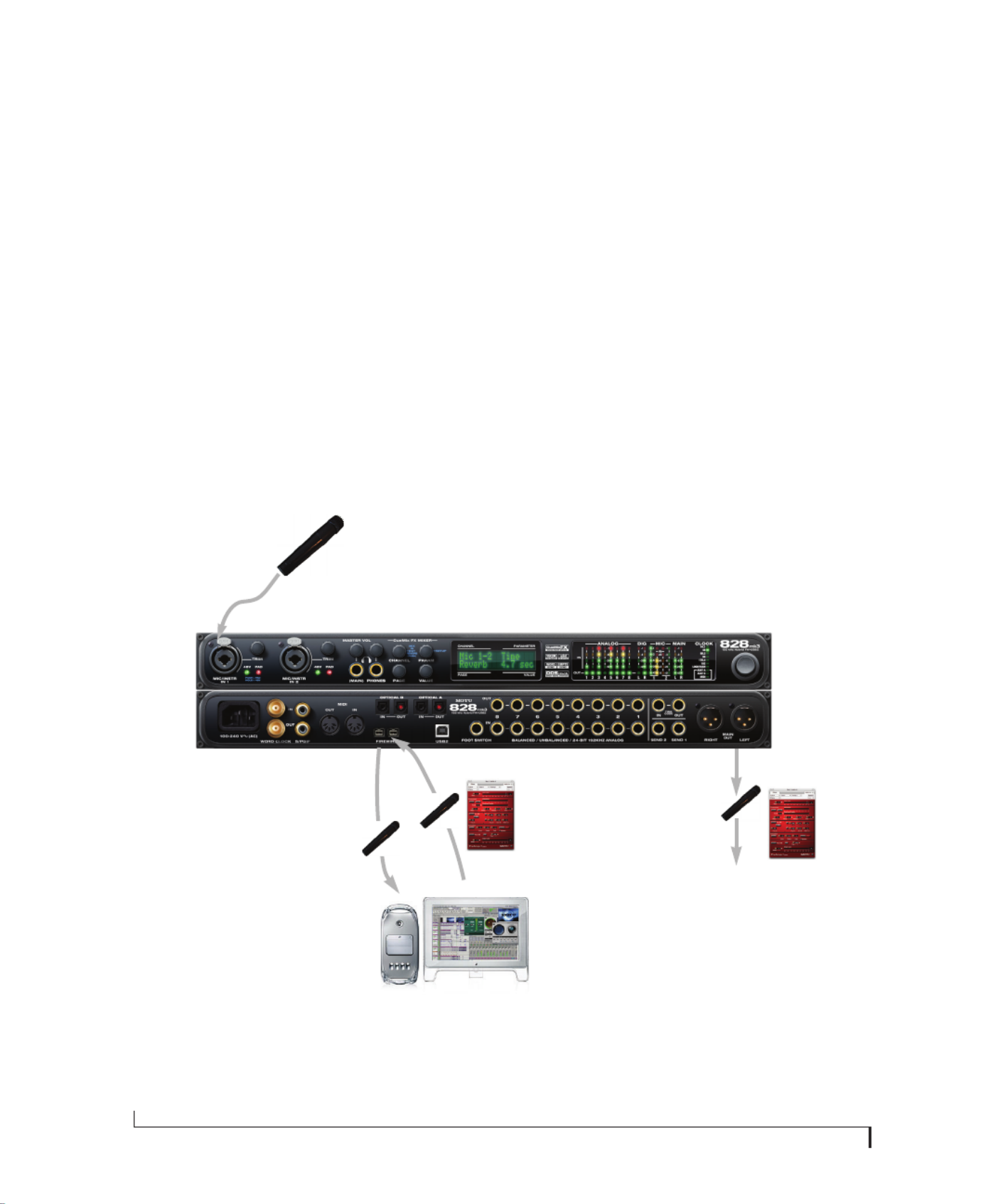
R E D U C I N G M O N I T O R I N G L A T E N C Y
68
MONITORING LIVE INPUT
There are two ways to monitor live audio input
with an 828mk3: 1) through the computer or 2) via
the 82mk3 CueMix FX hardware mixer. Figure 9-1
shows method 1, which allows you to apply host-
based effects processing via plug-ins in your audio
software. See the next section, “Adjusting the audio
I/O buffer” for details about how to reduce — and
possibly eliminate — the audible monitoring delay
that the computer introduces.
Figure 9-2 shows how to use CueMix FX hardware-
based monitoring, which lets you hear what you are
recording with no monitoring delay and no
computer-based effects processing. Instead, input
is routed directly to an output, either with or
without 828mk3-based effects processing (EQ,
compression or reverb). See “CueMix FX hardware
monitoring” later in this chapter for details on how
to use CueMix FX with your audio software, or
with the included CueMix FX software.
If the material you are recording is suitable, there is
a third way to monitor live input: use both methods
(Figure 9-1 and Figure 9-2) at the same time. For
example, you could route guitar to both the
computer (for an amp model effect) and mix that
processed signal on the main outs with dry guitar
from CueMix FX — or perhaps with a touch of
828mk3 Classic Reverb.
1. Live input (from mic, guitar, etc.)
enters the MOTU interface.
Mac
2. Mic signal goes immedi-
ately to the computer.
3. Mic signal is
‘patched thru’ back to
the audio interface
with host-based
plug-in effects, if any.
Figure 9-1: There are two ways to monitor live audio inputs with an 828mk3: 1) through the computer or 2) via CueMix FX hardware monitor-
ing. This diagram shows method 1 (through the computer). When using this method, use your host software’s buffer setting to reduce the
slight delay you hear when monitoring the live input, but don’t lower it too much, or your computer might get sluggish.
4. Mic signal (with plug-in
processing, if any) is routed
to the main outs (or other
outputs that you’ve specied
in the software).
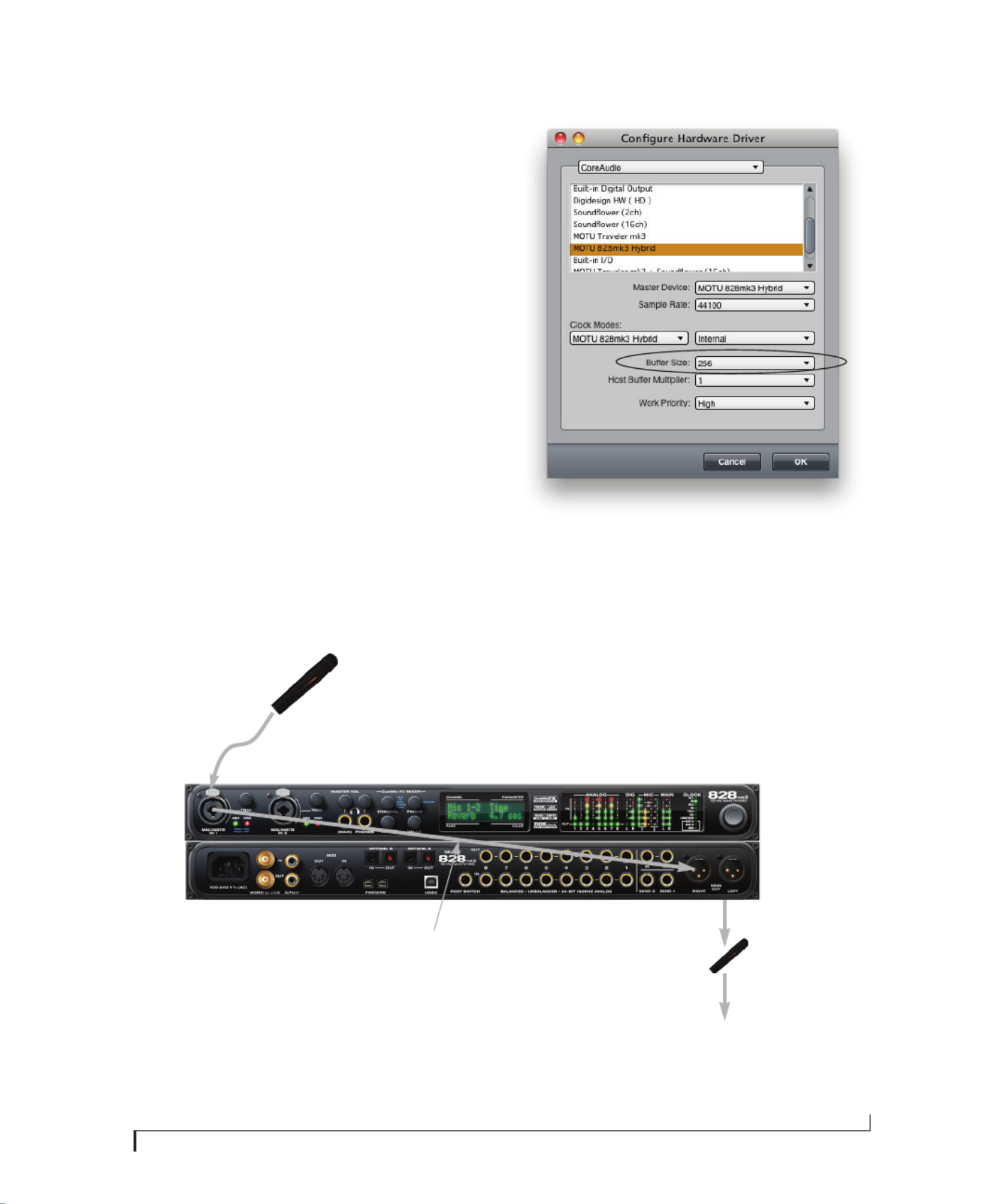
R E D U C I N G M O N I T O R I N G L A T E N C Y
69
ADJUSTING THE AUDIO I/O BUFFER
A buffer is a small amount of computer memory
used to hold data. For audio interfaces like the
828mk3, buffers are used for the process of
transferring audio data in and out of the computer.
The size of the buffers determines how much delay
you hear when monitoring live inputs through
your audio software: larger buffers produce more
delay; smaller buffers produce less.
Under Mac OS X, audio I/O buffer size is handled
by the host audio application (not the 828mk3
Core Audio driver). Most audio software
applications provide an adjustable audio buffer
setting that lets you control the amount of delay
you’ll hear when monitoring live inputs or
processing them with software plug-ins. Below are
a few examples.
Figure 9-3: In Digital Performer and AudioDesk, choose Setup menu>
Configure Audio System> Configure Hardware Driver to open the
dialog shown above and access the Buffer Size setting. Refer to your
Digital Performer or AudioDesk manual for information about the
Host Buffer Multiplier setting.
2. CueMix FX immediately patches the
live mic signal directly to the main outs
(or other output), completely bypassing
the computer. This signal could be dry, or
with 828mk3 effects processing, such as
EQ, compression or Classic Reverb.
3. Mic signal is mixed with the
main outs, and you can control
the volume (relative to the rest
of the mix) with the mic’s fader
in CueMix FX.
Figure 9-2: This diagram shows the signal flow when using CueMix FX no-latency monitoring. Notice that this method does not process the
live input with plug-ins in your audio software. Instead, you can apply 828mk3 effects, such as the reverb, EQ and/or compression.
1. Live input (from mic, guitar, etc.)
enters the MOTU interface.
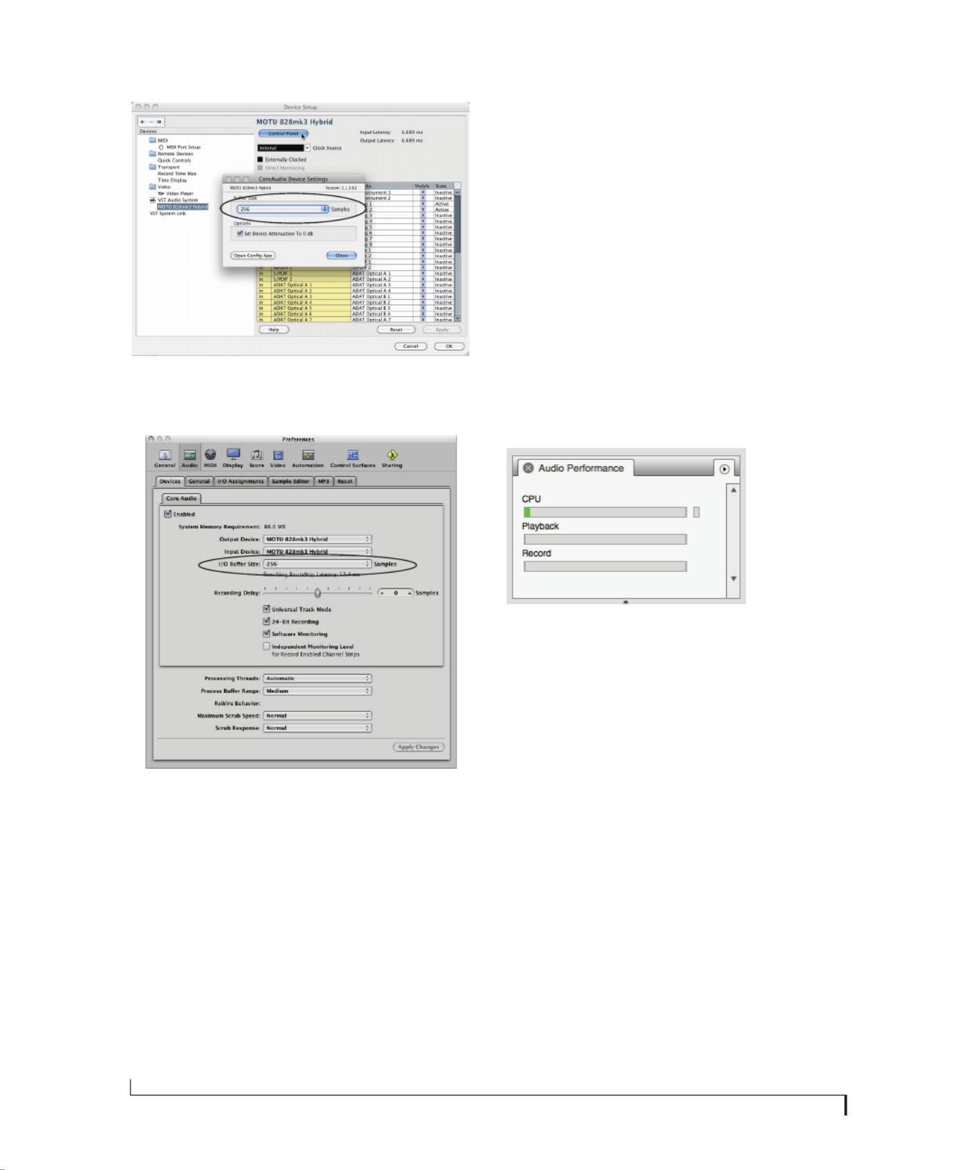
R E D U C I N G M O N I T O R I N G L A T E N C Y
70
Figure 9-4: In Cubase or Nuendo, choose Devices menu > Device
Setup. Select MOTU 828mk3 Hybrid, then click the Control Panel
button to access the window above and the Buffer Size setting.
Figure 9-5: In Logic Pro or Logic Express, go to the Audio Driver prefer-
ences to access the Buffer Size option shown above.
Lower latency versus higher CPU overhead
The buffer setting has a large impact on the
following things:
■Patch thru latency
■The load on your computer’s CPU
■Possible distortion at the smallest settings
■How responsive the transport controls are in
AudioDesk, Digital Performer or other audio
software
The buffer setting presents you with a trade-off
between the processing power of your computer
and the delay of live audio as it is being patched
through your software. If you reduce the size, you
reduce patch thru latency, but significantly increase
the overall processing load on your computer,
leaving less CPU bandwidth for things like real-
time effects processing. On the other hand, if you
increase the buffer size, you reduce the load on
your computer, freeing up bandwidth for effects,
mixing and other real-time operations.
Figure 9-6: When adjusting the buffer size to reduce monitoring
latency, watch the ‘processor ’ meter in Digital Performer or
AudioDesk’s Performance Monitor. If you hear distortion, or if the
Performance meter is peaking, try raising the buffer size.
If you are at a point in your recording project where
you are not currently working with live, patched-
thru material (e.g. you’re not recording vocals), or
if you have a way of externally processing inputs,
choose a higher buffer size. Depending on your
computer’s CPU speed, you might find that settings
in the middle work best (256 to 1024).
Transport responsiveness
Buffer size also impacts how quickly your audio
software will respond when you begin playback,
although not by amounts that are very noticeable.
Lowering the buffer size will make your software
respond faster; raising the buffer size will make it a
little bit slower, but barely enough to notice.

R E D U C I N G M O N I T O R I N G L A T E N C Y
71
Effects processing and automated mixing
Reducing latency with the buffer size setting has
another benefit: it lets you route live inputs through
the real-time effects processing and mix
automation of your audio software.
CUEMIX FX HARDWARE MONITORING
The 828mk3 has a more direct method of patching
audio through the system. This method employs
the 828mk3’s CueMix FX digital mixer. When
enabled, CueMix activates hardware patch-thru in
the 828mk3 itself. CueMix FX has two important
benefits:
■First, it completely eliminates the patch thru
delay (reducing it to a small number of samples —
about the same amount as one of today’s digital
mixers).
■Secondly, CueMix FX imposes no strain on the
computer.
The trade-off, however, is that CueMix FX
bypasses your host audio software. Instead, live
audio inputs are patched directly through to
outputs in the 828mk3 itself and are mixed with
audio playback from your host audio software.
This means that you cannot apply host-based
plug-ins, mix automation, or other real-time
effects that your audio software provides. But for
inputs that don’t need these types of features,
CueMix FX is the way to go.
On the other hand, if you really need to use the
mixing and processing provided by your audio
software, you should not use CueMix FX. Instead,
reduce latency with the buffer setting (as explained
earlier in this chapter).
TWO METHODS FOR CONTROLLING
CUEMIX FX
There are two ways to control CueMix FX:
■With CueMix FX
■From within your host audio software (if it
supports direct hardware monitoring)
You can even use both methods simultaneously.
Using CueMix FX
If your host audio software does not support direct
hardware monitoring, you run the CueMix FX
software side-by-side with your audio software and
manage your monitor mix in CueMix FX.
CueMix FX allows you to create up to eight
separate 828mk3 stereo mixes, or any other desired
routing configurations. These routings are
independent of your host audio software. For
complete details, see chapter 10, “CueMix FX”
(page 73).
Controlling CueMix FX from your audio
software
Some audio applications allow you to control
CueMix FX monitoring from within the
application (without the need to use CueMix FX).
In most cases, this support consists of patching an
828mk3 input directly to an output when you
record-arm a track. Exactly how this is handled
depends on the application.
The following applications are among those that
support direct control over CueMix FX:
■Digital Performer
■AudioDesk
CueMix FX routings that are made via host
applications are made “under the hood”, which
means that you won’t see them in CueMix FX.
However, CueMix FX connections made inside
your host audio software dovetail with any other
mixes you’ve set up in CueMix FX. For example, if
your host application routes audio to an output
pair that is already being used in CueMix FX for an
entirely separate mix bus, both audio streams will
simply be merged to the output.

R E D U C I N G M O N I T O R I N G L A T E N C Y
72
Controlling CueMix FX from within AudioDesk
or Digital Performer
To turn on CueMix FX in AudioDesk and Digital
Performer:
1From the Setup menu, choose Configure Audio
System>Input Monitoring Mode.
2Choose the Direct hardware playthrough option,
as shown below in Figure 9-7.
3From the Studio menu, choose Audio Patch
Thru, and choose any monitoring mode except Off.
Figure 9-7: Enabling CueMix FX in AudioDesk or Digital Performer.
Note: the ‘Only during recording...’ and ‘Always’ options are for
AudioDesk 2 and DP4 only. Later versions of DP have expanded input
monitoring features. Consult your documentation.
Once enabled, CueMix FX monitoring is tied with
Digital Performer or AudioDesk’s Audio Patch
Thru feature: when you record-enable a track, the
track’s input is routed directly to its output (via
CueMix FX in the 828mk3 hardware). For
example, if you record-enable a track called guitar
in your DP or AudioDesk project, and its audio
input assignment is Analog in 2, and its audio
output assignment is optical channels 7-8,
CueMix FX no-latency hardware monitoring will
automatically be set up from analog in 2 to optical
outputs 7-8.
Controlling CueMix DSP from within other
software
Consult the manual for your software.

CHAPTER
73
10 CueMix FX
OVERVIEW
CueMix FX is a cross-platform software
application that provides graphic, on-screen
control for the 828mk3 Hybrid’s flexible CueMix
FX on-board mixer and effects processing.
CueMix FX can be used independently of host
audio software, or together with it. CueMix
dovetails with the direct monitoring features of
your host audio software, allowing you to
seemlessly mix in both environments.
For information about programming the 828mk3’s
on-board mixing and effects using the front panel
LCD, see chapter 6, “Front Panel Operation”
(page 43).
A 16-bus mixer with EQ, compression and reverb . . . . 74
Advantages over host-based mixing and processing 74
CueMix FX installation . . . . . . . . . . . . . . . . . . . . . . . . . . . . . . . 75
CueMix FX basic operation . . . . . . . . . . . . . . . . . . . . . . . . . . . 75
The Mixes tab . . . . . . . . . . . . . . . . . . . . . . . . . . . . . . . . . . . . . . . . 77
The Inputs tab. . . . . . . . . . . . . . . . . . . . . . . . . . . . . . . . . . . . . . . . 79
The Outputs tab. . . . . . . . . . . . . . . . . . . . . . . . . . . . . . . . . . . . . . 81
The channel settings section . . . . . . . . . . . . . . . . . . . . . . . . . 83
The Monitor Group. . . . . . . . . . . . . . . . . . . . . . . . . . . . . . . . . . . 96
DSP meter. . . . . . . . . . . . . . . . . . . . . . . . . . . . . . . . . . . . . . . . . . . . 97
Solo light. . . . . . . . . . . . . . . . . . . . . . . . . . . . . . . . . . . . . . . . . . . . . 97
Talkback and listenback. . . . . . . . . . . . . . . . . . . . . . . . . . . . . . 97
Shortcuts. . . . . . . . . . . . . . . . . . . . . . . . . . . . . . . . . . . . . . . . . . . . . 99
File menu. . . . . . . . . . . . . . . . . . . . . . . . . . . . . . . . . . . . . . . . . . . . . 99
Edit menu . . . . . . . . . . . . . . . . . . . . . . . . . . . . . . . . . . . . . . . . . . .100
Devices menu . . . . . . . . . . . . . . . . . . . . . . . . . . . . . . . . . . . . . . .100
FFT and Spectrogram display . . . . . . . . . . . . . . . . . . . . . . .100
Oscilloscope. . . . . . . . . . . . . . . . . . . . . . . . . . . . . . . . . . . . . . . . .103
X-Y Plot. . . . . . . . . . . . . . . . . . . . . . . . . . . . . . . . . . . . . . . . . . . . . .109
Phase Analysis . . . . . . . . . . . . . . . . . . . . . . . . . . . . . . . . . . . . . .112
Tuner. . . . . . . . . . . . . . . . . . . . . . . . . . . . . . . . . . . . . . . . . . . . . . . .116
Configurations menu . . . . . . . . . . . . . . . . . . . . . . . . . . . . . . .116
Talkback menu. . . . . . . . . . . . . . . . . . . . . . . . . . . . . . . . . . . . . .117
Phones menu . . . . . . . . . . . . . . . . . . . . . . . . . . . . . . . . . . . . . . .117
Control Surfaces menu. . . . . . . . . . . . . . . . . . . . . . . . . . . . . .117

C U E M I X F X
74
A 16-BUS MIXER WITH EQ, COMPRESSION
AND REVERB
All 828mk3 inputs and outputs can be routed to the
on-board CueMix FX 16-bus (8 stereo bus) digital
mixer driven by hardware-based DSP with 32-bit
floating point precision.
The CueMix FX mixer allows you to apply no-
latency effects processing to inputs, outputs or
busses directly in the 828mk3 hardware,
independent of the computer. Effects can even be
applied when the 828mk3 is operating stand-alone
(without a computer) as a complete rack-mounted
mixer. Input signals to the computer can be
recorded wet, dry, or dry with a wet monitor mix
(for musicians during recording, for example).
Effects include:
■Classic Reverb with tail lengths up to 60 seconds
■7-band parametric EQ modeled after British
analog console EQs
■A standard compressor with conventional
threshold/ratio/attack/release/gain controls
■The Leveler™, an accurate model of the
legendary LA-2A optical compressor, which
provides vintage, musical automatic gain control
The 838mk3’s flexible effects architecture allows
you to apply EQ and compression on every input
and output (a total of 58 channels), with enough
DSP resources for at least one band of parametric
EQ and compression on every channel at 48 kHz.
DSP resources are allocated dynamically and a
DSP meter in the CueMix FX software allows you
to keep tabs on the 828mk3’s processing resources.
Each input, output and mix bus provides a send to
the Classic Reverb processor, which then feeds
reverb returns to mix busses and outputs, with a
selectable split point between them to prevent
send/return feedback loops.
ADVANTAGES OVER HOST-BASED MIXING
AND PROCESSING
CueMix FX provides several major advantages over
mixing and processing in your host audio software:
■CueMix has no buffer latency. Thanks to the
828mk3’s DSP chip, CueMix provides the same
throughput performance as a digital mixer.
■CueMix mixing and effects processing imposes
no processor drain on the computer’s CPU.
■CueMix routing can be maintained
independently of individual software applications
or projects.
■CueMix routing can operate without the
computer, allowing the 828mk3 to operate as a
portable, stand-alone mixer with effects.

C U E M I X F X
75
CUEMIX FX INSTALLATION
CueMix FX is installed with the rest of your
828mk3 software.
CUEMIX FX BASIC OPERATION
Here is a brief overview of the CueMix FX mixer.
Eight stereo mix busses
CueMix provides eight stereo mix busses: Bus 1,
Bus 2, Bus 3, and so on. Each mix bus can take any
number of inputs and mix them down to any
828mk3 output pair that you choose. For example,
Bus 1 could go to the headphones, Bus 2 could go to
the main outs, Bus 3 could go to a piece of outboard
gear connected to analog outputs 7-8, etc.
Many inputs to one output pair
It might be useful to think of each mix bus as some
number of inputs all mixed down to a stereo output
pair. CueMix FX lets you choose which inputs to
include in the mix, and it lets you specify the level,
pan and other input-specific mix controls for each
input being fed into the mix.
Viewing one mix bus at a time
CueMix FX displays one mix bus at a time in the
Mixes tab (Figure 10-2 on page 77). To select which
mix you are viewing, choose it from the mix bus
menu (Figure 10-2). The mix name appears above
the mix bus master fader (Figure 10-2), where you
can click the name to change it.
Figure 10-1: CueMix FX is a virtual mixer that gives you control over the 828mk3’s on-board mixing features.
Tabs for inputs,
mix busses and
outputs
DSP
resources
meter
828mk3
inputs
Mix bus
master
fader
Tabs for channel strip settings,
including EQ and dynamics, as
well as global settings such as
the meter bridge and reverb
processor.
Monitoring/
talkback
section
Monitor
group
metering
Mic inputs Inputs split
into mono
channels
Inputs grouped as
stereo pairs
MIx bus
menu
Channel
settings
Channel
focus
Grow
box
Channel
scroll
bar
Solo
light

C U E M I X F X
76
Each mix bus is independent
Each mix bus has its own settings. Settings for one
bus will not affect another. For example, if an input
is used for one bus, it will still be available for other
busses. In addition, inputs can have a different
volume, pan, mute and solo setting in each bus.
Input channels
The Inputs tab (Figure 10-3 on page 79) gives you
access to settings for individual 828mk3 inputs (or
input pairs), such as phase, trim, EQ and dynamics
processing. Each input also includes a send to the
828mk3’s global reverb processor. These settings
are applied to the signal before it goes anywhere
else (to a mix bus or the computer).
Output channels
The Outputs tab (Figure 10-6 on page 82) gives you
access to settings for each 828mk3 output pair,
including EQ, dynamics processing and send/
return controls for feeding and returning the
output signal to/from the 828mk3’s global reverb
processor. These settings are applied to the signal
just before it is sent to the output.
Channel focus and settings
Click the focus button for a channel (Figure 10-1)
to view channel-specific parameters in the Channel
Settings section of the CueMix FX window
(Figure 10-1). Separate tabs are provided for
channel-specific settings (channel strip, EQ and
dynamics), plus the global meter bridge and reverb
processor.
Global reverb processor
The 828mk3 has a global reverb module
(Figure 10-23 on page 95). Once it has been
activated, you can feed signals to the reverb
processor from various points in the 828mk3 mix
matrix via input sends, bus sends and output
sends. Stereo output from the reverb processor can
then be fed back to mix busses or output pairs
using reverb returns.
Other features
CueMix offers many additional features, discussed
in this chapter, such as talkback/listenback,
extensive metering, graphic editing of certain
effects parameters, monitor grouping and more.
Widening the CueMix FX window
To view more input faders at once, drag the grow
box (Figure 10-1) to the right.

C U E M I X F X
77
THE MIXES TAB
Click the Mixes tab (Figure 10-2) to gain access to
the 828mk3’s eight stereo mix busses. The Mixes
tab displays one mix bus at a time.
Viewing a mix
Choose the mix you wish to view from the mix bus
menu (in the Mixes tab itself, as shown in
Figure 10-2). The menu shows all mixes by name,
followed by the 828mk3 output pair to which each
bus master fader is currently assigned, if any.
Naming a mix
Click the mix name at the top of the mix bus master
fader (Figure 10-2) to edit the name.
Assigning a mix bus output
Choose the desired output pair for the mix bus
from the bus output menu (Figure 10-2). The bus
output menu displays all current available
(enabled) 828mk3 output pairs. If a bus is already
assigned to an output pair, the bus name appears
next to the output pair name to indicate that the
output pair is already taken by a bus. Only one bus
can be assigned to any given output pair. If you
choose an output already assigned to another bus,
that bus output will become disabled.
Bus fader
The bus fader (Figure 10-2) controls the overall
level of the mix (its volume on its stereo output).
Use the individual input faders to the left to control
individual input levels.
Figure 10-2: The Mixes tab.
828mk3
inputs
Mix bus 1
master
fader
Mic inputs Inputs grouped as
stereo pairs
Mixes
tab
Input name
Channel focus
Input pan section
Input fader
Scroll bar for input
channels
Bus output
Bus Reverb
send/return
Bus name
Bus fader
Bus mute
Bus level meter
Input mute/solo
Input level meter
Mix bus
menu

C U E M I X F X
78
Bus mute
The bus mute button (Figure 10-2) disables
(silences) the mix.
Bus level meter
The bus level meter, which is post-fader, shows you
the output for the mix’s output.
Bus reverb send/return
The bus reverb send (Figure 10-2) feeds the output
of the mix bus, pre-fader, to the 828mk3’s global
reverb processor, where it is merged with any other
signals being fed to the reverb. The reverb’s output
can then be fed back into the mixer at various
return points, including the bus return (discussed
below).
The bus reverb return (Figure 10-2) feeds the
output of the 828mk3’s global reverb processor
into the mix bus, pre-fader. This includes any other
signals currently being fed to the reverb. The bus
reverb return is disabled (grayed out) when the
reverb Split Point is set to Output to eliminate the
possibility for feedback loops created by reverb
send/return loops. See “Split point” on page 95.
Input section
The horizontally scrolling area in the Mix tab to the
left of the master fader (Figure 10-2) displays
channel strips for all currently enabled 828mk3
inputs.
Naming an input
Click the input name at the top of the input channel
strip (Figure 10-2) to edit the name. Input names
are global across all mixes. This name also appears
in host audio software on the computer (if the
software supports channel names).
Input channel focus
Click the channel focus button (Figure 10-3) to
view and edit parameters in the channel settings
section of the CueMix FX window (Figure 10-7 on
page 83). Clicking the mix bus master fader focus
button brings the assigned output into focus, if
there is one.
Input pan section
The input pan knob (Figure 10-2) pans the input
across the bus stereo outputs. If the input itself is
grouped as a stereo pair (in the Inputs tab), two
forms of panning control are provided:
Balance
Balance works like the balance knob on some
radios: turn it left and the right channel dims, turn
it right and left channel dims. But the left channel
always stays left and the right channel stays right.
Width
Width spreads the left and right channels across the
stereo image, depending on the knob position.
Maximum value (turning the pan knob all the way
up) maintains the original stereo image: the left
channel goes entirely left and right goes entirely
right, without attenuation. The minimum value
(turning the knob all the way down) creates a
mono effect: equal amounts of left and right are
combined and sent to both outputs. In between,
the left out is a mixture of the left input and some of
the right input (and vice-versa) with the effect of
narrowing the field.
Input fader and mute/solo
To add an input to a mix, or remove it, click its
Mute button. To solo it, use its Solo button. Use the
input fader (Figure 10-2) to adjust the level for the
input in the mix. Note that an input can have
different level, pan, mute and solo settings for
different mixes. Input channel level meters are
post-fader.
If any solo button on the current (active) bus is
enabled, the Solo Light (Figure 10-1) will
illuminate.
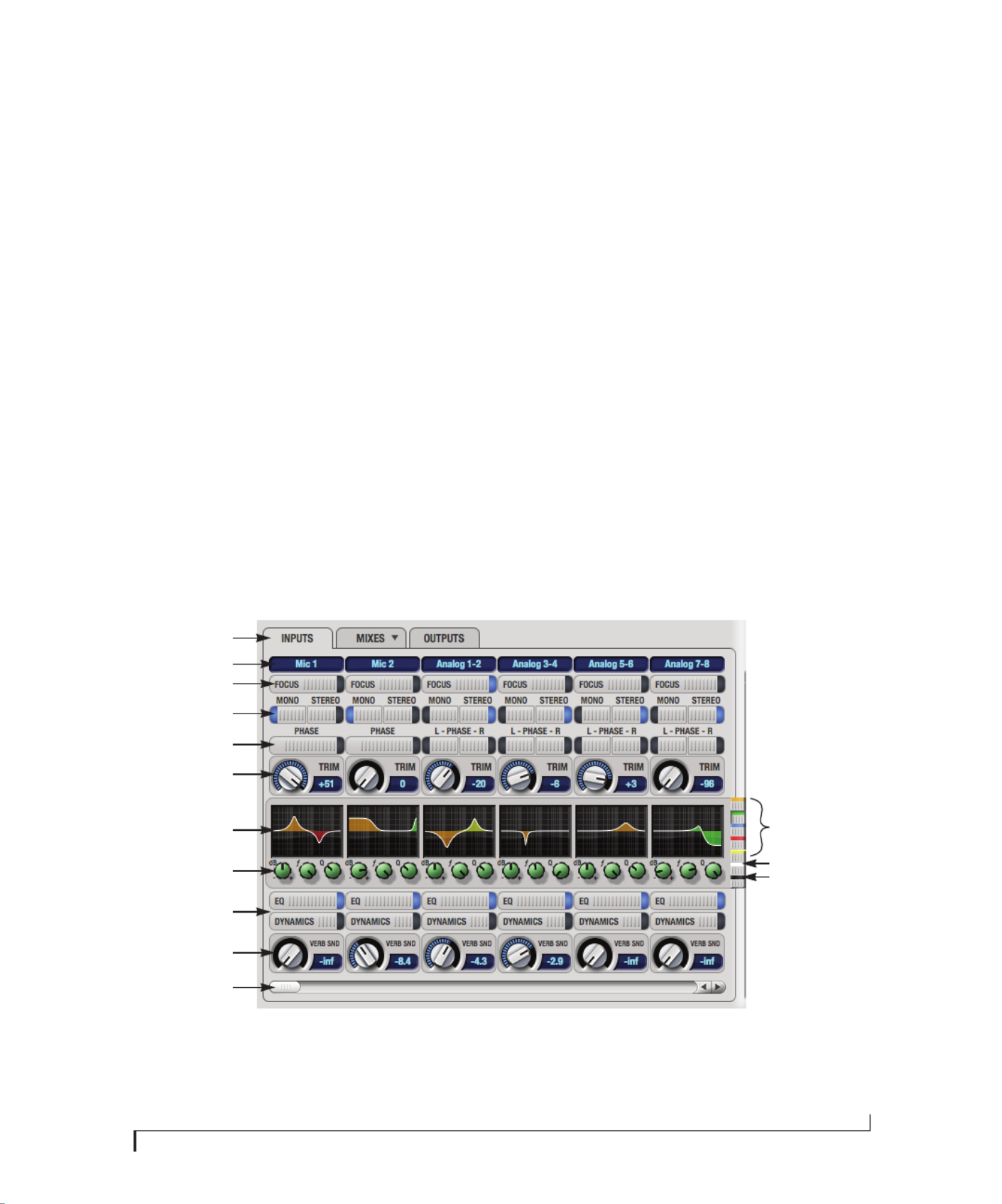
C U E M I X F X
79
THE INPUTS TAB
The 828mk3 provides many features for managing
analog and digital input signals. Some of these
features, such as the 828mk3’s digitally controlled
analog trims, are implemented in the analog
domain; others are implemented in the digital
domain as DSP applied to the digital signal (after
the A/D converter on analog inputs). Click the
Inputs tab (Figure 10-3) to access and control all of
these input channel settings for each 828mk3 input
or input pair.
Input tab settings are global
Except for the reverb send, all settings you make in
the Input tab are applied to the input signal before
it goes anywhere else (to a mix bus or the
computer). For example, if you apply EQ and
compression to the input signal, you will record the
processed version of the signal in your host audio
software running on the computer. If you need to
record a completely unprocessed input signal, do
not apply any changes to it in the Input tab. The
only exception to this is the reverb send, which
simply splits the input signal and feeds a copy of it
to the 828mk3’s reverb processor.
Signal flows from top to bottom
Settings in each Input tab channel strip are
generally applied to the signal in order from top to
bottom. Input channel signal flow is as follows:
trim, overload protection, phase, stereo versus M/S
decoding, width, L/R swap, EQ, dynamics and
reverb send.
Naming an input
Click the input name at the top of the input channel
strip (Figure 10-3) to edit the name. Input names
are global across all mixes. This name also appears
in host audio software on the computer (if the
software supports channel names).
Figure 10-3: The Inputs tab.
Input name
Channel focus
Mono/stereo paring
Invert phase
Input trim
EQ/dynamics graph
EQ/dynamics controls
EQ/dynamics
enable/disable
Reverb send
Input scroll bar
EQ band selectors
LP/HP filter selector
Compressor selector
Inputs tab

C U E M I X F X
81
Figure 10-4: The EQ/Dynamics selectors.
Click the selector (Figure 10-4) for the desired EQ
band, low-pass (LP) filter, high pass (HP) filter or
compressor to view it across all channels.
Figure 10-5: The Compressor controls.
☛Shortcut: hold down the Option/Alt key while
clicking an EQ selector button to show just that
band of EQ in the graphs. Click any selector again
to return to viewing all bands.
Using the EQ/Dynamics knobs
Once you have chosen the desired EQ band, or the
compressor, you can modify its settings using the
two or three knobs below the graph. The knobs
match the color of the currently selected effect, to
help remind you of which effect you are currently
editing.
☛Important: before you can modify the settings
of an EQ band using the three knobs below the
graph, the EQ band must be enabled. This is done
in the EQ tab (Figure 10-10), as explained in
“Enabling EQ” on page 85.
EQ/Dynamics enable/disable buttons
Click the EQ or Dynamics button at the bottom of
the input channel (Figure 10-3) to toggle the effect
on or off. Note that you can program EQ and
compressor settings, even when the effect is
currently disabled. (You just won’t hear the result
until you enable it.)
Reverb send
The input reverb send (Figure 10-3) feeds the input
signal to the 828mk3’s global reverb processor,
where it is merged with any other signals being fed
to the reverb. The reverb’s output can then be fed
back into a mix or output pair. The send occurs
after all other settings in the input channel strip
(phase invert, EQ, compression, etc.)
THE OUTPUTS TAB
The Outputs tab (Figure 10-6) lets you apply EQ,
dynamics and reverb to any output pair, just before
the signal leaves the 828mk3. This is processing
that occurs at the very end of the signal flow, after
everything else (host based effects, 828mk3 input
or bus processing, mixing, and so on). Processing
is done in the digital domain, just before the signal
goes analog through the D/A converter. Output tab
processing is applied to the entire output mix (all
signals being mixed to the output from various
sources).
Signal flows from top to bottom
Settings in each Output tab channel strip are
applied to the signal in order from top to bottom.
For example, EQ occurs before Dynamics, which is
applied before the reverb send and return.
Naming an output
Click the output name at the top of the output
channel strip (Figure 10-6) to edit the name.
Output names are global and will also appear in
host audio software on the computer (if the
software supports channel names).
EQ band selectors
LP/HP filter selector
Compressor selector
Colored knobs
Orange
Green
Blue
Red
Yellow
White
Black
Compressor
graph
Compressor
meter
Compressor
selector

C U E M I X F X
82
Output channel focus
Click the channel focus button (Figure 10-6) to
view and edit parameters in the channel settings
section of the CueMix FX window (Figure 10-7 on
page 83).
Output EQ and Dynamics
The EQ/Dynamics section in the Outputs tab
(Figure 10-6) works identically to the EQ/
Dynamics section for the Inputs tab (Figure 10-3).
See “Input EQ and dynamics” on page 80.
Output reverb send/return
The output reverb send (Figure 10-6) feeds the
signal for the output to the 828mk3’s global reverb
processor, where it is merged with any other signals
being fed to the reverb. The reverb’s output can
then be fed back into the mixer at various return
points, including the same output from which it
was sent (discussed below). The output reverb
send is disabled (grayed out) when the reverb Split
Point is set to Mix to eliminate the possibility for
feedback loops created by reverb send/return
loops. See “Split point” on page 95.
The output reverb return (Figure 10-6) feeds the
output of the 828mk3’s global reverb processor
directly to the output. This includes any other
signals currently being fed to the reverb.
Both the send and return occur after EQ and
dynamics processing, but before listenback and
talkback.
Talkback/Listenback
Click the Talkback or Listenback buttons
(Figure 10-6) to toggle whether the output pair is
included in the Talkback or Listenback group. See
“Talkback and listenback” on page 97.
Monitor group assign
Click the Monitor buttons (Figure 10-6) to toggle
whether the output pair is included in the Monitor
group. See “The Monitor Group” on page 96.
Figure 10-6: The Outputs tab.
Output name
Channel focus
Outputs tab
EQ band selectors
LP/HP filter selector
Compressor selector
EQ/Dynamics graph
EQ/Dynamics controls
EQ/Dynamics
enable/disable
Output reverb
send/return
Talkback/listenback
enable/disable
Monitor group assign
Specyfikacje produktu
| Marka: | Motu |
| Kategoria: | system hi-fi |
| Model: | 828mk3 Hybrid |
Potrzebujesz pomocy?
Jeśli potrzebujesz pomocy z Motu 828mk3 Hybrid, zadaj pytanie poniżej, a inni użytkownicy Ci odpowiedzą
Instrukcje system hi-fi Motu

11 Stycznia 2025
22 Września 2024
22 Września 2024
22 Września 2024
22 Września 2024
22 Września 2024
22 Września 2024
22 Września 2024
1 Września 2024
1 Września 2024
Instrukcje system hi-fi
- system hi-fi Sony
- system hi-fi Yamaha
- system hi-fi Samsung
- system hi-fi AEG
- system hi-fi Sven
- system hi-fi LG
- system hi-fi Motorola
- system hi-fi Logitech
- system hi-fi Sharp
- system hi-fi BeamZ
- system hi-fi Huawei
- system hi-fi Pioneer
- system hi-fi Philips
- system hi-fi Plantronics
- system hi-fi SilverCrest
- system hi-fi Technics
- system hi-fi JBL
- system hi-fi Onkyo
- system hi-fi Roland
- system hi-fi Geemarc
- system hi-fi Nokia
- system hi-fi Scott
- system hi-fi KEF
- system hi-fi Kärcher
- system hi-fi Bose
- system hi-fi Panasonic
- system hi-fi Klipsch
- system hi-fi Muse
- system hi-fi Crestron
- system hi-fi Behringer
- system hi-fi Asus
- system hi-fi Nedis
- system hi-fi IK Multimedia
- system hi-fi Medion
- system hi-fi Boss
- system hi-fi OK
- system hi-fi Lenco
- system hi-fi Marquant
- system hi-fi Majestic
- system hi-fi Jensen
- system hi-fi ILive
- system hi-fi Native Instruments
- system hi-fi Garmin
- system hi-fi Blaupunkt
- system hi-fi Vivax
- system hi-fi ATen
- system hi-fi Salora
- system hi-fi Teac
- system hi-fi Dual
- system hi-fi Grundig
- system hi-fi Kiloview
- system hi-fi Homedics
- system hi-fi Soundmaster
- system hi-fi Hyundai
- system hi-fi DAP-Audio
- system hi-fi Creative
- system hi-fi Manhattan
- system hi-fi Honor
- system hi-fi Tripp Lite
- system hi-fi Shure
- system hi-fi ECG
- system hi-fi Matsui
- system hi-fi Denon
- system hi-fi Block
- system hi-fi Cambridge
- system hi-fi Sanus
- system hi-fi Kenwood
- system hi-fi Scosche
- system hi-fi Polk
- system hi-fi Alpine
- system hi-fi Gembird
- system hi-fi Røde
- system hi-fi Dynaudio
- system hi-fi Paradigm
- system hi-fi Bang & Olufsen
- system hi-fi Cobra
- system hi-fi JVC
- system hi-fi Konig & Meyer
- system hi-fi Memphis Audio
- system hi-fi Jamo
- system hi-fi Focusrite
- system hi-fi Rega
- system hi-fi Steelseries
- system hi-fi Oppo
- system hi-fi Lowrance
- system hi-fi TechniSat
- system hi-fi Auna
- system hi-fi Vimar
- system hi-fi Schneider
- system hi-fi LD Systems
- system hi-fi Krüger&Matz
- system hi-fi Audioengine
- system hi-fi OneConcept
- system hi-fi Pure
- system hi-fi Marshall
- system hi-fi Clarion
- system hi-fi Netgear
- system hi-fi Thomson
- system hi-fi Pro-Ject
- system hi-fi AVM
- system hi-fi Velleman
- system hi-fi Ferguson
- system hi-fi Korg
- system hi-fi DataVideo
- system hi-fi Magnat
- system hi-fi DreamGEAR
- system hi-fi Pyle
- system hi-fi ELAC
- system hi-fi Zoom
- system hi-fi Cardo
- system hi-fi NGS
- system hi-fi Midland
- system hi-fi Marantz
- system hi-fi AOC
- system hi-fi Monster
- system hi-fi Sennheiser
- system hi-fi Esoteric
- system hi-fi Jabra
- system hi-fi Chord
- system hi-fi Camry
- system hi-fi Vtech
- system hi-fi Werma
- system hi-fi Speco Technologies
- system hi-fi Lenoxx
- system hi-fi Bowers & Wilkins
- system hi-fi Samson
- system hi-fi Imperial
- system hi-fi PreSonus
- system hi-fi Monitor Audio
- system hi-fi Audio Pro
- system hi-fi NACON
- system hi-fi Revox
- system hi-fi Nevir
- system hi-fi Olympus
- system hi-fi TriStar
- system hi-fi Ibiza Sound
- system hi-fi Vonyx
- system hi-fi Musical Fidelity
- system hi-fi Alto
- system hi-fi Fluid
- system hi-fi Razer
- system hi-fi Peavey
- system hi-fi ION
- system hi-fi ART
- system hi-fi NAD
- system hi-fi Continental Edison
- system hi-fi RCF
- system hi-fi Harman Kardon
- system hi-fi Rolls
- system hi-fi Audio-Technica
- system hi-fi SPC
- system hi-fi GoGen
- system hi-fi TC Helicon
- system hi-fi NEC
- system hi-fi Brandson
- system hi-fi Sonoro
- system hi-fi Parrot
- system hi-fi Aiwa
- system hi-fi JL Audio
- system hi-fi AKAI
- system hi-fi Majority
- system hi-fi Teufel
- system hi-fi Clatronic
- system hi-fi Dali
- system hi-fi Vision
- system hi-fi Telefunken
- system hi-fi Oregon Scientific
- system hi-fi Focal
- system hi-fi DBX
- system hi-fi Kicker
- system hi-fi Omnitronic
- system hi-fi Hama
- system hi-fi Mackie
- system hi-fi Shokz
- system hi-fi Marmitek
- system hi-fi FiiO
- system hi-fi Duronic
- system hi-fi Smart-AVI
- system hi-fi MXL
- system hi-fi Lotronic
- system hi-fi Bush
- system hi-fi Sharkoon
- system hi-fi Watson
- system hi-fi Saramonic
- system hi-fi Loewe
- system hi-fi Bluesound
- system hi-fi Sangean
- system hi-fi AVer
- system hi-fi Walrus Audio
- system hi-fi SVS
- system hi-fi Franklin
- system hi-fi Victrola
- system hi-fi Arcam
- system hi-fi Elta
- system hi-fi Mac Audio
- system hi-fi Infinity
- system hi-fi McIntosh
- system hi-fi Denver
- system hi-fi Albrecht
- system hi-fi Hitachi
- system hi-fi Fender
- system hi-fi AKG
- system hi-fi SmallHD
- system hi-fi RCA
- system hi-fi Electro Harmonix
- system hi-fi Atlas Sound
- system hi-fi Gemini
- system hi-fi Trevi
- system hi-fi Technaxx
- system hi-fi Atlona
- system hi-fi GPX
- system hi-fi Arturia
- system hi-fi Sencor
- system hi-fi Polsen
- system hi-fi PowerBass
- system hi-fi Power Dynamics
- system hi-fi Rockford Fosgate
- system hi-fi Steinberg
- system hi-fi Canton
- system hi-fi Nextbase
- system hi-fi Senal
- system hi-fi TOA
- system hi-fi Monacor
- system hi-fi Daewoo
- system hi-fi ADE
- system hi-fi Tannoy
- system hi-fi Electro-Voice
- system hi-fi Anthem
- system hi-fi Audizio
- system hi-fi Tascam
- system hi-fi RME
- system hi-fi Laser
- system hi-fi WAGAN
- system hi-fi Kunft
- system hi-fi Best Buy
- system hi-fi AudioControl
- system hi-fi Audiolab
- system hi-fi Vocopro
- system hi-fi Technical Pro
- system hi-fi WiiM
- system hi-fi SPL
- system hi-fi Cyrus
- system hi-fi Terratec
- system hi-fi Crunch
- system hi-fi Geneva
- system hi-fi Sound Devices
- system hi-fi House Of Marley
- system hi-fi Reflexion
- system hi-fi REVO
- system hi-fi DPA
- system hi-fi Crosley
- system hi-fi HK Audio
- system hi-fi Swissvoice
- system hi-fi Fenton
- system hi-fi BSS Audio
- system hi-fi Belkin
- system hi-fi SWIT
- system hi-fi Kramer
- system hi-fi KanexPro
- system hi-fi RGBlink
- system hi-fi Glide Gear
- system hi-fi Hosa
- system hi-fi Key Digital
- system hi-fi Music Hall
- system hi-fi AMX
- system hi-fi Goodis
- system hi-fi Sonance
- system hi-fi Rotel
- system hi-fi Altec Lansing
- system hi-fi American Audio
- system hi-fi Devialet
- system hi-fi IFi Audio
- system hi-fi Audison
- system hi-fi Caliber
- system hi-fi Sony Ericsson
- system hi-fi Proscan
- system hi-fi Exibel
- system hi-fi Logik
- system hi-fi Energy Sistem
- system hi-fi Sagem
- system hi-fi Sonos
- system hi-fi Brigmton
- system hi-fi Sunstech
- system hi-fi AudioAffairs
- system hi-fi Magnum
- system hi-fi Steren
- system hi-fi Audiosonic
- system hi-fi Coby
- system hi-fi Envivo
- system hi-fi Galaxy Audio
- system hi-fi Bigben Interactive
- system hi-fi Apogee
- system hi-fi Pyle Pro
- system hi-fi Autotek
- system hi-fi MB Quart
- system hi-fi Bigben
- system hi-fi Massive
- system hi-fi IDance
- system hi-fi Alba
- system hi-fi Naxa
- system hi-fi QTX
- system hi-fi Konig
- system hi-fi Boston Acoustics
- system hi-fi Mpman
- system hi-fi Vizio
- system hi-fi Nikkei
- system hi-fi Peaq
- system hi-fi Ematic
- system hi-fi ESI
- system hi-fi Roadstar
- system hi-fi Anchor Audio
- system hi-fi Superior
- system hi-fi Quantis
- system hi-fi Irradio
- system hi-fi Karcher Audio
- system hi-fi Cmx
- system hi-fi Russound
- system hi-fi Comica
- system hi-fi Audient
- system hi-fi Bluetrek
- system hi-fi Starkey
- system hi-fi PAC
- system hi-fi Skytec
- system hi-fi Luxman
- system hi-fi M-Audio
- system hi-fi Stereoboomm
- system hi-fi Tivoli Audio
- system hi-fi Wolfgang
- system hi-fi Numan
- system hi-fi Iluv
- system hi-fi Vankyo
- system hi-fi WyreStorm
- system hi-fi Sonifex
- system hi-fi TV One
- system hi-fi Nxg
- system hi-fi Lynx
- system hi-fi MIPRO
- system hi-fi Solid State Logic
- system hi-fi HiFi ROSE
- system hi-fi OSD Audio
- system hi-fi Andover
- system hi-fi Mark Levinson
- system hi-fi Auto-T
- system hi-fi Soundstream
- system hi-fi Xoro
- system hi-fi Adastra
- system hi-fi Avante
- system hi-fi Titanwolf
- system hi-fi CSL
- system hi-fi Liam&Daan
- system hi-fi Universal Audio
- system hi-fi JB Systems
- system hi-fi Orbitsound
- system hi-fi HUMANTECHNIK
- system hi-fi SIIG
- system hi-fi Hercules
- system hi-fi Primare
- system hi-fi Griffin
- system hi-fi Xantech
- system hi-fi Eissound
- system hi-fi Extron
- system hi-fi ClearOne
- system hi-fi Ebode
- system hi-fi Mission
- system hi-fi Teradek
- system hi-fi TCM
- system hi-fi Crown
- system hi-fi Morel
- system hi-fi Zvox
- system hi-fi Antelope Audio
- system hi-fi CE Labs
- system hi-fi Z CAM
- system hi-fi Avid
- system hi-fi Icon
- system hi-fi Mtx Audio
- system hi-fi General Electric
- system hi-fi Aquatic AV
- system hi-fi Parasound
- system hi-fi Promate
- system hi-fi SoundCast
- system hi-fi Hollyland
- system hi-fi Defender
- system hi-fi Boytone
- system hi-fi Astell&Kern
- system hi-fi Glorious
- system hi-fi Maretron
- system hi-fi JK Audio
- system hi-fi Xact
- system hi-fi Ruark Audio
- system hi-fi Magnavox
- system hi-fi ANT
- system hi-fi Leviton
- system hi-fi Rane
- system hi-fi ESX
- system hi-fi NUVO
- system hi-fi Lexicon
- system hi-fi Fluance
- system hi-fi Altra
- system hi-fi On-Q
- system hi-fi Vantage Point
- system hi-fi Planet Audio
- system hi-fi CAD Audio
- system hi-fi IFi
- system hi-fi E-bench
- system hi-fi Digigram
- system hi-fi Roon
- system hi-fi Voco
- system hi-fi Linear
- system hi-fi SSV Works
- system hi-fi DAP
- system hi-fi The Box
- system hi-fi AmpliVox
- system hi-fi Audiofrog
- system hi-fi Accsoon
- system hi-fi Juke Audio
- system hi-fi Meridian
- system hi-fi DiGiGrid
- system hi-fi CLXmusic
- system hi-fi Nuheara
- system hi-fi Acoustic Solutions
- system hi-fi Metric Halo
- system hi-fi Universal Remote Control
- system hi-fi Prism Sound
- system hi-fi MoFi
- system hi-fi Antelope
- system hi-fi Auvi
- system hi-fi Switchcraft
- system hi-fi Aplic
- system hi-fi Crystal Video
- system hi-fi Atoll
- system hi-fi Bennett & Ross
- system hi-fi Pronomic
- system hi-fi Beatfoxx
- system hi-fi NEAR
- system hi-fi Vaxis
- system hi-fi INKEE
Najnowsze instrukcje dla system hi-fi

9 Kwietnia 2025

5 Kwietnia 2025
3 Kwietnia 2025
2 Kwietnia 2025
2 Kwietnia 2025
1 Kwietnia 2025
1 Kwietnia 2025
29 Marca 2025
28 Marca 2025
28 Marca 2025