Instrukcja obsługi Lightware HDMI-OPT-RX200R
Lightware
przedłużacz AV
HDMI-OPT-RX200R
Przeczytaj poniżej 📖 instrukcję obsługi w języku polskim dla Lightware HDMI-OPT-RX200R (36 stron) w kategorii przedłużacz AV. Ta instrukcja była pomocna dla 4 osób i została oceniona przez 2 użytkowników na średnio 4.5 gwiazdek
Strona 1/36

HDMI-OPT-TX100, HDMI-OPT-RX100
HDMI-OPT-TX100R, HDMI-OPT-RX100R
HDMI-OPT-TX200R, HDMI-OPT-RX200R
User’s Manual
Fiber Optical Multimedia Extender

HDMI-OPT series – User's Manual 2
Important Safety Instructions
Class II apparatus construction.
The equipment should be operated only from the power source
indicated on the product.
To disconnect the equipment safely from power, remove the power
cord from the rear of the equipment, or from the power source. The
MAINS plug is used as the disconnect device, the disconnect device
shall remain readily operable.
There are no user-serviceable parts inside of the unit. Removal of the
cover will expose dangerous voltages. To avoid personal injury, do not
remove the cover. Do not operate the unit without the cover installed.
The appliance must be safely connected to multimedia systems.
Follow instructions described in this manual.
Ventilation
For the correct ventilation and to avoid overheating ensure enough
free space around the appliance. Do not cover the appliance, let the
ventilation holes free and never block or bypass the ventilators (if any).
WARNING
To prevent injury, the apparatus is recommended to securely attach to
the oor/wall or mount in accordance with the installation instructions.
The apparatus shall not be exposed to dripping or splashing and that
no objects lled with liquids, such as vases, shall be placed on the
apparatus. No naked ame sources, such as lighted candles, should
be placed on the apparatus.
Waste Electrical & Electronic Equipment
WEEE
This marking shown on the product or its literature,
indicates that it should not be disposed with other
household wastes at the end of its working life. To
prevent possible harm to the environment or human
health from uncontrolled waste disposal, please
separate this from other types of wastes and recycle it
responsibly to promote the sustainable reuse of material
resources. Household users should contact either the
retailer where they purchased this product, or their local government
ofce, for details of where and how they can take this item for
environmentally safe recycling. Business users should contact their
supplier and check the terms and conditions of the purchase contract.
This product should not be mixed with other commercial wastes for
disposal.
Caution: Laser product
Common Safety Symbols
Symbol Description
Direct current
Alternating current
Double insulation
Caution, possibility of eletric shock
Caution
Laser radiation
INVISIBLE LASER RADIATION
AVOID DIRECT EYE EXPOSURE
CLASS 3R LASER PRODUCT
Radiated wavelenght:
778 nm, 800 nm, 825 nm, 850 nm, 911 nm, 980 nm
Output power <= 1 mW
Classified by EN 60825-1:2007

HDMI-OPT series – User's Manual 3
Symbol Legend
The following symbols and markings are used in the document:
WARNING! Safety-related information which is highly
recommended to read and keep in every case!
ATTENTION! Useful information to perform a successful procedure;
it is recommended to read.
INFO: A notice which may contain additional information. Procedure
can be successful without reading it.
DEFINITION: The short description of a feature or a function.
TIPS AND TRICKS: Ideas which you may have not known yet but can
be useful.
Navigation Buttons
Go back to the previous page. If you clicked on a link previously,
you can go back to the source page by clicking the button.
Navigate to the Table of Contents.
Step back one page.
Step forward to the next page.
Document Information
All presented functions refer to the indicated products. The descriptions
have been made during testing these functions in accordance with the
indicated Hardware/Firmware/Software environment:
Item Version
Lightware Device Controller (LDC) software 1.23.2b1
Lightware Bootloader Software 3.3.3
Controller rmware - HDMI-OPT-TX series 1.9.7.b1
Controller rmware - HDMI-OPT-RX series 1.9.7.b1
Hardware 2.0
Document revision: 3.0
Release date: 13-08-2018
Editor: Judit Barsony
About Printing
Lightware Visual Engineering supports green technologies and
eco-friend mentality. Thus, this document is made for digital usage
primarily. If you need to print out few pages for any reason, follow the
recommended printing settings:
▪Page size: A4
▪Output size: Fit to page or Match page size
▪Orientation: Landscape
TIPS AND TRICKS: Thanks to the size of the original page, the
border around the content (grey on the second picture below)
makes possible to organize the pages better. After punching the
printed pages, they can be placed easily into a ring folder.
12 3

HDMI-OPT series – User's Manual 4
1. INTRODUCTION 5 ...................................................................................
1.1. Description ...................................................................................5
1.2. Box Contents ................................................................................5
1.3. Model Comparison ........................................................................5
1.4. Features of the Device .................................................................. 6
1.5. Compatible Devices .......................................................................6
1.6. Typical Application ......................................................................6
2. INSTALLATION 7 .....................................................................................
2.1. Mounting Options .........................................................................7
2.1.1. 1U High Rack Shelf ............................................................................ 7
2.1.2. Under-desk Mounting Kit .................................................................. 7
2.1.3. Under-desk Double Mounting Kit ...................................................... 7
2.2. Connecting Steps..........................................................................8
2.2.1. Baud Rate Settings ............................................................................ 9
3. PRODUCT OVERVIEW 10 ......................................................................
3.1. HDMI-OPT Series Receivers ........................................................10
3.2. HDMI-OPT Series Transmitters .................................................. 11
3.3. Electrical Connections .............................................................. 12
3.3.1. DC 5V Connection ........................................................................... 12
3.3.2. HDMI Inputs and Outputs ............................................................... 12
3.3.3. SC Fiber Input and Output ............................................................... 12
3.3.4. RS-232 Connectors.......................................................................... 12
3.4. Optical Extender Concept .......................................................... 13
3.5. HDMI Output Settings ................................................................13
3.6. RS-232 Signal Transmission .......................................................14
4. OPERATION 15 .......................................................................................
4.1. Front Panel LEDs ........................................................................15
4.1.1. Primary and Secondary Modes 15 ......................................................
4.1.2. The Legend of Status LEDs 15 ............................................................
4.1.3. Transmitter LED Modes .................................................................. 16
4.1.4. Receiver LED Modes ....................................................................... 16
4.2. EDID Operations ..........................................................................17
4.2.1. About EDID Memory ........................................................................ 17
4.2.2. Switching EDID ................................................................................ 17
4.2.3. Learning EDID .................................................................................. 17
4.2.4. Deleting EDID ................................................................................... 17
5. SOFTWARE CONTROL - LIGHTWARE DEVICE CONTROLLER 18 ....
5.1. Install and Upgrade ...................................................................18
5.2. Establishing the Connection .....................................................19
5.3. I/O Parameters Menu ..................................................................20
5.4. EDID Menu .................................................................................... 20
5.4.1. Sources and Destinations ............................................................... 21
5.4.2. EDID Operations .............................................................................. 21
5.4.3. EDID Summary Window .................................................................. 21
5.4.4. Editing an EDID ................................................................................ 22
5.4.5. Creating an EDID.............................................................................. 22
5.5. Settings Menu .............................................................................23
5.5.1. Device Information .......................................................................... 23
5.5.2. Log .................................................................................................... 23
5.6. Terminal Window ........................................................................24
6. FIRMWARE UPGRADE 25 ......................................................................
6.1. Upgrading Steps in a Nutshell ...................................................25
6.2. Detailed Instructions ................................................................. 25
7. TROUBLESHOOTING 28 ........................................................................
8. TECHNOLOGIES 29 ................................................................................
8.1. EDID Management .......................................................................29
8.1.1. Understanding the EDID .................................................................. 29
8.1.2. Advanced EDID Management ......................................................... 29
8.2. HDCP Management ...................................................................... 30
8.2.1. Protected and Unprotected Content .............................................. 30
8.2.2. Real Life Examples .......................................................................... 30
8.3. Pixel Accurate Reclocking ........................................................31
8.4. Serial Management ..................................................................... 32
8.4.1. General Information ....................................................................... 32
8.4.2. Types of Serial Cables ..................................................................... 32
8.4.3. RS-232 Signal Transmission over Lightware Extender Devices ... 32
9. APPENDIX ..........................................................................................33
9.1. Specification ...............................................................................33
9.2. Maximum Extension Distances ...................................................34
9.3. Mechanical Drawings .................................................................34
9.4. Factory EDID List ........................................................................ 35
9.5. Further Information ..................................................................36
Table of Contents

1. Introduction HDMI-OPT series – User's Manual 6
1.4. Features of the Device
INFO: Certain features depend on the conguration of the model. For more information about the models
see section.Model Comparison
Advanced EDID Management
The user can emulate any EDID on the inputs independently, read out and store any attached
monitor's EDID in 100 internal memory locations, upload and download EDID les using
Lightware Device Controller software.
Pixel Accurate Reclocking
Each output has a clean, jitter free signal, eliminating signal instability and distortion caused
by long cables or connector reections.
1080p
HDTV Supports All HDTV Resolutions
720p, 1080i and 1080p etc. with or without HDCP encoding. Signals with up to 225 MHz pixel
clock frequency - regardless of the resolution - are passed through.
HDCP Compliant
The HDMI-OPT extenders support HDCP encrypted HDMI signal transmission.
Cross Compatibility
Cross compatibility between all the devices in the product series is ensured thanks to
Lightware’s attentive design. Any transmitter can be paired with any receiver without
restriction. With Lightware’s hybrid modular matrix concept, it is even possible to connect an
extender box directly to the matrix router using an MX-HDMI-OPT series input or output board
(MX-HDMI-OPT-IB or MX-HDMI-OPT-OB).
0
1
2
3
4
5
6
7
8
9
Front Panel Control on the Transmitter
EDID address selection with two decimal rotary switches and LEARN button are available for
Advanced EDID Management. On the HDMI-OPT-TX200R and TX100R the BAUD RATE rotary
switch allows selecting the appropriate speed of serial communication.
1.5. Compatible Devices
The HDMI-OPT series devices are compatible with the following:
Transmitters
▪HDMI-OPT-RX100, HDMI-OPT-RX100R, HDMI-OPT-RX200R receivers;
▪MX-FR modular frames with MX-HDMI-OPT-IB-SC card.
Receivers
▪HDMI-OPT-TX100, HDMI-OPT-TX100R, HDMI-OPT-TX200R transmitters;
▪MX-FR modular frames with MX-HDMI-OPT-OB-SC card.
1.6. Typical Application
Application examples
▪Long distance lossless HDMI or DVI signal transmission
▪Ground loop isolation
▪Multiroom video and audio control
▪Professional AV systems, conference rooms
▪High End home cinema
▪Yacht installations
Standalone Application Diagram
Integrated System Diagram
R
R
HDMI
HDMI
HDMI
HDMI
5V DC
Power
adaptor
HDMI-OPT-TX200R HDMI-OPT-RX200R
Blu-ray Player
Local Monitor
Projector
Monitor
5V DC
Power
adaptor
R
INPUT 1 INPUT 8
INPUT 7
INPUT 6
INPUT 5
INPUT 4
INPUT 3
INPUT 2
HDCP
HDMI
SCDT
+5V
HDCP
HDMI
SCDT
+5V
12V 6A DC IN
MX-HDMI-TP-OB
VIDEO 1 DDC 1 VIDEO 2 DDC 2 VIDEO 3 DDC 3 VIDEO 4 DDC 4 VIDEO 5 DDC 5 VIDEO 6 DDC 6 VIDEO 7 DDC 7 VIDEO 8 DDC 8
12V 4A DC IN
MX-HDMI-TP-IB
VIDEO 1 DDC 1 VIDEO 2 DDC 2 VIDEO 3 DDC 3 VIDEO 4 DDC 4 VIDEO 5 DDC 5 VIDEO 6 DDC 6 VIDEO 7 DDC 7 VIDEO 8 DDC 8
MX-DVI-OPT-OB-SC
8CH OPTICAL OUTPUT BOARD
LASER ACTIVE
HDCP
HDMI
FIBER LINK
L.A
HDCP
HDMI
FIBER LINK
LASER ACTIVE
HDCP
HDMI
FIBER LINK
LASER ACTIVE
HDCP
HDMI
FIBER LINK
LASER ACTIVE
HDCP
HDMI
FIBER LINK
MX-DVI-OPT-OB-SC IN 1 IN 2
IN 3 IN 4 IN 5 IN 6 IN 7 IN 8
8CH OPTICAL OUTPUT BOARD
LASER DETECT
HDCP
HDMI
SIGNAL PRESET
L.D
HDCP
HDMI
SIGNAL
LASER DETECT
HDCP
HDMI
SIGNAL PRESET
LASER DETECT
HDCP
HDMI
SIGNAL PRESET
LASER DETECT
HDCP
HDMI
SIGNAL PRESET
MX-DVI-HDCP-OB
DVI 1.0 HDMI 1.3 HDCP 1.3 COMPLIANT 8 CH OUTPUT BOARD
MX-DVI-HDCP-IB
DVI 1.0 HDMI 1.3 HDCP 1.3 COMPLIANT 8 CH INPUT BOARD
IN 1 IN 2 IN 3 IN 4 IN 5 IN 6 IN 7 IN 8
R
Blu-ray Player
Local Monitor
Projector
Monito
HDMI-OPT-RX200R
HDMI-OPT-TX200R
Blu-ray Player
Laptop
Monitor
HDMI
HDMI
HDMI
HDMI
HDMI
HDMI
HDMI
5V DC
Power
adaptor
5V DC
Power
adaptor
Single fiber
multimode
optical cable
up to 2600m
Single fiber
multimode
optical cable
up to 2600m
2. Installation HDMI-OPT series – User's Manual 7
2
Installation
The chapter is about the installation of the device and connecting to other
appliances, presenting also the mounting options and further assembly steps:
Ý
Ý
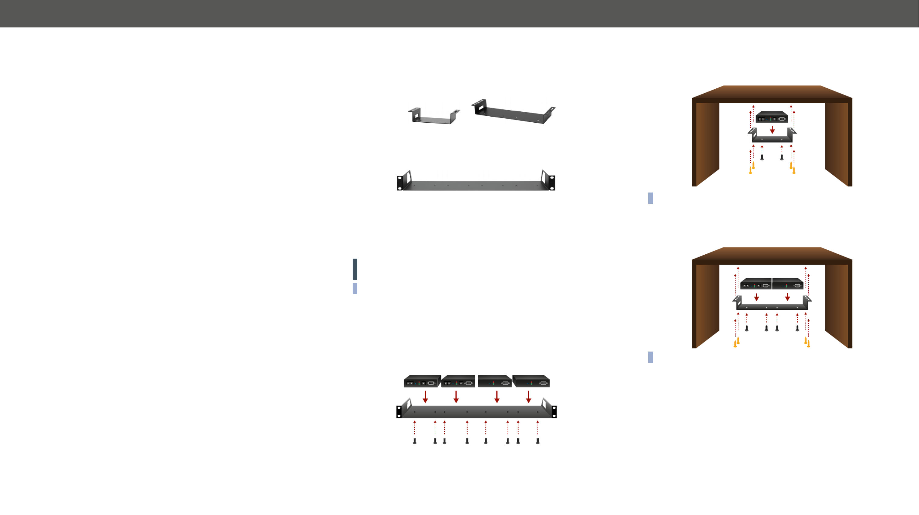
2.1. Mounting Options
To mount the extenders Lightware supplies optional accessories for
different usage. There are three kinds of mounting kits with similar
Under-desk
mounting kit
Under-desk double
mounting kit
1U high rack shelf
The device has two mounting holes with inner thread on the bottom
side; see the bottom view in Mechanical Drawings section. Fasten the
device by the screws enclosed to the accessory.
To order mounting accessory kits please contact sales@lightware.com.
WARNING! Always use the supplied screws. Using different (e.g.
longer) ones may cause damage to the device.
INFO: The extenders are quarter-rack sized.
2.1.1. 1U High Rack Shelf
Allows rack mounting for half-rack, quarter-rack and pocket sized
units.
1U high rack shelf provides mounting holes for fastening two half-
rack or four quarter-rack sized units. Pocket sized devices can also be
fastened on the self.
2.1.2. Under-desk Mounting Kit
surface (e.g. furniture).
INFO: The chipboard screws are not supplied with the mounting kit.
2.1.3. Under-desk Double Mounting Kit
The UD-kit double makes it easy to mount a single device or multiple
INFO: The chipboard screws are not supplied with the mounting kit.

2. Installation HDMI-OPT series – User's Manual 8
2.2. Connecting Steps
Transmitter side
OPTM
Connect a multimode (OPTM) ber cable to the SC ber output port of the transmitter.
HDMI
Connect the source (e.g. a PC) to the HDMI input port of the transmitter by a HDMI cable.
HDMI
Optionally connect a local display (e.g. monitor) to the output port. 1
RS-232
Optionally connect a controller device (e.g. touch panel) to the RS-232 port of the transmitter. 2
Power
Firstly connect the power adaptor to the DC input of the transmitter, then to the AC power
socket.
Receiver side
OPTM
Connect a multimode (OPTM) ber cable to the SC ber input port of the receiver.
HDMI
Connect the sink (e.g. a projector) to the HDMI output port of the receiver by a HDMI cable.
HDMI
Optionally connect a controlled device (e.g. projector) to the RS-232 port of the receiver. 3
RS-232
Optionally connect a secondary display (e.g. HDTV) to the HDMI OUT 2 port. 4
Power
Firstly connect the power adaptor to the DC input of the receiver, then to the AC power socket.
1 Only in the case of HDMI-OPT-TX200R model.
2 Only in the case of HDMI-OPT-TX100R/TX200R models.
3 Only in the case of HDMI-OPT-RX100R/RX200R models.
4 Only in the case of HDMI-OPT-RX200R model.
WARNING! Please do not look directly into the SC ber optical connector if the cable is connected to the
transmitter only and the laser is active.
INFO: Powering the devices on is recommended to do as the nal step during the installation.
PC
HDMI-OPT series
transmitter
Power adaptor
Projector
Transmitter side Receiver side
Touch panel
Power
RS-232HDMI
OPTM
Power adaptor
Power
Monitor
HDMI HDMI
HDMI-OPT ser
receiver
HDTV
HDMI
RS-232

2. Installation HDMI-OPT series – User's Manual 9
2.2.1. Baud Rate Settings
HDMI-OPT units use some of the standard timings for the RS-232
pass-through. To work the bidirectional serial communication well
between serial ending devices users must choose the proper baud rate
on the transmitter units. Please read the serial devices’ user’s manual
to nd the appropriate baud rates. The best one is both devices’ most
common value.
If the communication speed ability of a serial device is unknown use
the lowest (#0: 9600) value.
To use Lightware Device Controller or Lightware Bootloader software
select the #9 position (SW control).
Baud Rate Rotary on the HDMI-OPT-TX200R model
Rotary switch
position BAUD rate
0 9600
1 14400
2 19200
3 38400
4 57600
5 Not used
6 Not used
7 Not used
8 Not used
9 SW control
Baud Rate Rotary Switch Values

3. Product Overview HDMI-OPT series – User's Manual 10
3
Product Overview
The following sections are about the physical structure of the device, input/
output ports and connectors:
Ý
Ý
Ý
Ý
Ý
Ý
3.1. HDMI-OPT Series Receivers
HDMI-OPT-RX100 - Front and Rear View
HDMI-OPT-RX100R - Front and Rear View
HDMI-OPT-RX200R - Front and Rear View
1Status LEDs The LEDs give feedback about the state of units and video signal. For more
information see section.The Legend of Status LEDs
2RS-232 port 9-pole D-sub male connector. Connect a serial cable between the receiver and the
serial device. For more details see section.Serial Management
3Function button Toggles the LED functions between PRIMARY (SOLID) SECONDARY (BLINKING) and .
For more information see section.Primary and Secondary Modes
45V DC input
5SC Fiber Input
6HDMI output Connect one HDMI cable between the receiver and the sink device.
7HDMI output 2 Connect one HDMI cable between the receiver and the secondary sink device.
1
5
4 6
1 2
5
4 6
3
1 2
5
4 6 7

3. Product Overview HDMI-OPT series – User's Manual 11
3.2. HDMI-OPT Series Transmitters
HDMI-OPT-TX100 - Front and Rear View
HDMI-OPT-TX100R - Front and Rear View
HDMI-OPT-TX200R - Front and Rear View
2
1 3
9
6 7
2
1 3 4 5
9
6 7
2
1 3 4 5
9
6 7 8
1EDID rotary
switches
The rotary switches select one of 99 addresses. EDID memories #1..#50
contain factory presets and #51..#99 are user programmable. For more
information see section.EDID Operations
2LEARN button Toggles the LED functions between PRIMARY (SOLID) SECONDARY (BLINKING) and .
For more information see section.Primary and Secondary Modes
3Status LEDs The LEDs give feedback about the state of units and video signal. For
more information about names and meanings of the Status LEDs see
The Legend of Status LEDs section.
4Baud rate rotary The rotary switch selects one of 5 speeds of the serial communication (#0..#4)
or the Software Control mode (#9).
5RS-232 port 9-pole D-sub female connector. Connect a serial cable between the transmitter
and the desired serial device. For more details see Serial Management section.
65V DC input Connect the output of the supplied 5V DC power adaptor.
7HDMI input Connect one HDMI cable between the HDMI source and the transmitter.
8MONITOR output Connect one HDMI cable between the local display device and the transmitter.
9SC Fiber output Connect a multimode single ber optical cable between the transmitter and
the receiver.

3. Product Overview HDMI-OPT series – User's Manual 13
3.4. Optical Extender Concept
HDMI-OPT series transmitters and receivers are a digital audio/video signal extenders with RS-232 signal
transmission. The transmitter receives HDMI video with embedded digital audio signal and transmits them
over a single multimode ber optical cable. Besides of the A/V signal the transmitter is able send RS-232
signal as well over the same optical line. The receiver accepts the optical signal and transmits to the sink
device. In the case of RX200R model two display devices can be attached to the receiver. The receiver is also
able to transmit the RS-232 commands to the controlled device.
Summary of Interfaces - Transmitters
* Only TX100R and TX200R models.
Summary of Interfaces - Receivers
** Only RX100R and RX200R models.
HDMI / DVI
RS-232 *
+ RS-232 *
INPUT
OPT HDMI / DVI
RS-232 *
OUTPUT
HDMI / DVI
RS-232 **
INPUT
OPT
HDMI / DVI
RS-232 **
OUTPUT
+ RS-232 **
3.5. HDMI Output Settings
HDMI-OPT unit is able to recognize the type of the incoming video signal and set automatically the proper
one to the output.
Auto output mode function determines the output signal (DVI or HDMI) by the source, emulated EDID and
the connected device’s EDID on the local MONITOR OUT. Table below contains the possible cases of the
signals’ type.
HDMI signal transmission example
Source Emulated EDID Local monitor EDID Output signal type
DVI DVI or HDMI DVI or HDMI DVI
HDMI DVI or HDMIDVI DVI
HDMI HDMI DVI DVI
HDMI HDMI HDMI HDMI
In the highlighted row (HDMI source, HDMI emulated EDID but only DVI capable monitor) colorspace
converting problems can appear. HDMI standard supports RGB and YUV (also known YCbCr) colorspaces
but DVI supports only the RGB. HDMI-OPT units do not support colorspace conversion between HDMI YUV
and RGB. If the source sends HDMI signal with YUV colorspace settings and the sink device can work only in
RGB mode the color components can be mismatched during the process. Monitor recognize Y component
as R, Cb as G and Cr as B. It causes wrong colors and the embedded audio frame of HDMI will be lost.
In most of the HDMI sources the colorspace can be set manually by the user. If not, an EDID must be
used which does not support YUV colorspace. This kind of EDID can be made easily with Lightware Device
Controller software. For the detailed instructions see section.Creating an EDID
INFO: EDIDs without CEA extension effect RGB colorspace but these EDIDs do not support HDMI
embedded audio.
Source
Transmitter Receiver Display
Local display
Output signal
Monitor EDID
Output signal
Emulated EDID

3. Product Overview HDMI-OPT series – User's Manual 14
3.6. RS-232 Signal Transmission
ATTENTION! Only HDMI-OPT-TX100R and TX200R transmitters and HDMI-OPT-RX100R and RX200R
receivers are built with RS-232 ports.
Technical Background
Serial data communication can be established via the local RS-232 port (D-SUB connector) and can be
transmitted via the optical line up to 2600 meter far. The RS-232 commands are received by the receiver
which can transmit them to the controllable device (e.g. a projector) via the local D-SUB port. This method
makes the extenders suitable to control any third-party device with RS-232 commands.
RS-232 Signal Transmission - Example
The Concept
The System controller sends messages over the RS-232 port of the Transmitter. The Transmitter sends the
messages over the optical line without any modication toward the Receiver. The Receiver sends the
messages to the which is recognized and executed them.Projector
INFO: Always check the baud rate of the sender and receiver devices. Do not forget to set up the correct
baud rate value on the rotary switch located on the transmitter's front panel.
System controller
RS-232 FIBER OPTICAL
HDMI-OPT series transmitter Projector
RS-232
HDMI-OPT series receiver

4. Operation
4
Operation
This chapter is about the powering and operating of the device describing the
functions which are available by the front/rear controls:
4.1. Front Panel LEDs
To save space and simplify readability HDMI-OPT unit uses only four LEDs to inform users about the
connections and the video signals. Because of the low numbers of LEDs two modes and several functions
are used for display information.
4.1.1. Primary and Secondary Modes
Two modes are available. In PRIMARY (SOLID) mode LEDs light continuously and give information about the
incoming connection and video signal. In SECONDARY (BLINKING) mode LEDs blink and give information
about EDID management and outgoing connections. Push down and release the button to change LEARN
between PRIMARY and SECONDARY mode.
INFO: LED modes were made for only showing information and do not affect applying changes with front
panel’s controls. The user can choose or learn EDID in either LED modes, even though the actual state is
not visible.
4.1.2. The Legend of Status LEDs
The legend shows the LEDs’ color and short description about the meaning can also be found on the top of
the devices.
HDMI-OPT-TX100 / HDMI-OPT-TX100R
PRIMARY (SOLID) SECONDARY (BLINKING)
HDCP ENCRYPTED CONTENT
HDMI SIGNAL
VIDEO CLOCK PRESENT
LINK - RECEIVER DETECTED
EMULATED EDID INVALID
EMULATED EDID VALID
SOURCE +5V SENSE
HDMI-OPT-TX200R
PRIMARY (SOLID) SECONDARY (BLINKING)
HDCP ENCRYPTED CONTENT
HDMI SIGNAL
VIDEO CLOCK PRESENT
LINK - RECEIVER DETECTED
EMULATED EDID INVALID
EMULATED EDID VALID
MONITOR OUT HOTPLUG SENSE
SOURCE +5V SENSE
HDMI-OPT-RX100 / HDMI-OPT-RX100R
HDCP ENCRYPTED CONTENT
HDMI SIGNAL
VIDEO CLOCK PRESENT
LASER DETECTED
HDMI-OPT-RX200R
PRIMARY (SOLID) SECONDARY (BLINKING)
HDCP ENCRYPTED CONTENT
HDMI SIGNAL
VIDEO CLOCK PRESENT
LASER DETECTED OUT1 MONITOR HOTPLUG SENSE
OUT2 MONITOR HOTPLUG SENSE
Ý
Ý

4. Operation HDMI-OPT series – User's Manual 16
4.1.3. Transmitter LED Modes
Status
LED
LED
mode Description TX100 TX100R TX200R
PRIMARY (SOLID) MODE
HDCP
encrypted
content
Indicates if the source signal is HDCP encrypted.
HDMI signal
Indicates the type of the video signal. In case of existing HDMI
signal the LED lights continuously. In case of existing DVI signal the
LED is off and the Video Clock present LED is lights continuously.
Video clock
present
Indicates if a valid HDMI clock signal is present on the transmitters’
HDMI input or the receivers’ SC multimode in connector.
Link -
Receiver
detected
Indicates if a powered receiver (e.g. RX200R) is connected to the
transmitter and they can communicate over the ber optical cable.
When no receiver is connected, and the transmitter powered, the
LED is blinking by 1Hz frequency.
SECONDARY (BLINKING) MODE
Emulated
EDID invalid
The LED lights red if the selected EDID is invalid or empty memory
selected.
After applying a Hot Plug signal(s) to the OUTPUT(s), this LED
indicates that the unit is trying to read the EDID from the connected
display device, but the EDID is invalid or missing.
After pressing the LEARN button, this LED’s blinking indicates if the
learn process was unsuccessful.
Emulated
EDID valid
The LED lights green if the selected EDID is valid.
After applying a Hot Plug signal(s) to the OUTPUT(s), this LED
indicates that the unit is reading the EDID from the connected
display device and the EDID is valid.
After pressing the LEARN button, this LED’s blinking indicates if the
learn process was successful.
Monitor
out hotplug
sense
- -
Indicates if a powered display device
(or matrix switcher, repeater, etc.) is
connected to the HDMI output connector
and sends a valid hotplug signal on pin
19 through the HDMI cable.
Source +5V
sense
Indicates if a powered source unit (computer, DVD or Blu-Ray
player, etc.) is connected to the HDMI INPUT connector and sends
a valid +5V signal on pin 18 through the HDMI cable.
4.1.4. Receiver LED Modes
Status
LED
LED
mode Description RX100 RX100R RX200R
PRIMARY (SOLID) MODE
HDCP
encrypted
content
Indicates if the source signal is HDCP encrypted.
HDMI signal
Indicates the type of the video signal. In case of existing HDMI
signal the LED lights continuously. In case of existing DVI signal the
LED is off and the Video Clock present LED is lights continuously.
Video clock
present
Indicates if a valid HDMI clock signal is present on the transmitters’
HDMI input or the receivers’ SC multimode in connector.
Laser
detected
Indicates if a powered transmitter (e.g. TX200R) is connected to the
receiver and they can communicate over the ber optical cable.
SECONDARY
(BLINKING)
MODE
Monitor out
hotplug sense
OUT1 / OUT2
- -
Indicates if a powered display
device (or matrix switcher,
repeater, etc.) is connected to the
HDMI output connector and sends
a valid hotplug signal on pin 19
through the HDMI cable.

4. Operation HDMI-OPT series – User's Manual 17
4.2. EDID Operations
ATTENTION! EDID settings are available in the HDMI-OPT series
transmitters only, the receivers are transparent in the video signal
point of view.
4.2.1. About EDID Memory
The EDID memory is non-volatile and can store 99 EDIDs. The memory
structure is as follows:
Description Rotary switch
state
Memory bank
number in LDC
Factory Preset EDID list #01 - #50 F01 - F50
User programmable slots U1 - U48#51 - #98
Last attached monitor’s EDID
(local monitor) #00 D01
INFO: HDMI-OPT series transmitters can handle both 128 Byte EDID
and 256 Byte extended EDID structures.
INFO: The attached monitor’s EDID is stored automatically, until a
new monitor is attached to the local monitor output. In the case of
powering the unit off, the last attached monitor’s EDID remains in
non-volatile memory.
INFO: The transmitters always learn the stored last attached
monitor’s EDID into the user programmable EDID memory.
Factory Preset EDIDs
The factory EDIDs (F1-F50) are factory preprogrammed and cannot
be modied. These are the most common resolutions. They are
specially provided to force graphic cards to output only the exact pixel
resolution and refresh rate.
Universal HDMI (F49) allows multiple resolutions including all common
VESA dened resolutions. The use of universal EDID is recommended
for fast and easy system setup.
You can nd all the factory preset EDID in Factory EDID List section.
INFO: The factory EDIDs (#1..#50 inclusive) preprogrammed and
cannot be modied. These are the most commonly used resolutions.
4.2.2. Switching EDID
The user can select an EDID to emulate on the input, this is called EDID
routing. There are two types of the emulation: static and dynamic.
▪Static EDID emulation happens, when an EDID from the Factory or
User EDID list is routed to an input.
▪Dynamic EDID emulation occurs, when an attached monitor’s EDID
is routed to an input. In this case the emulated EDID changes
automatically, if a new monitor is attached to the output, by
simply copying the data from the monitor.
Step 1. Use a screwdriver to change the memory address on the rotary
switches on the front side of the transmitter. The left switch sets
the tens value, the right switch gives the ones value of the EDID.
Location #17 is selected by the rotary switches
ATTENTION! Avoid the use of keys, coins, knives and other sharp
objects switching the rotary switches.
Step 2. After either one of the rotary switches has been rotated the unit
waits approximately two seconds before the selected EDID
becomes active.
Step 3. Check the status of the device on the Status LEDs. See the
The Legend of Status LEDs.
The address #00 has a special function in the case of HDMI-OPT-
TX200R. If a monitor is connected to the , then its is MONITOR OUT EDID
copied to the connector. If no monitor is connected to the HDMI INPUT
MONITOR OUT then the EDID transmitted to the INPUT connector is
the EDID of the last connected monitor.
0
1
2
3
4
5
6
7
8
9
0
1
2
3
4
5
6
7
8
9
4.2.3. Learning EDID
The factory preset EDIDs cannot be changed by the user. Only
addresses from #51 to #98 are user programmable.
Step 1. After connecting the sink device to HDMI OUTPUT, use a
screwdriver to select a user programmable memory address
on the rotary switches. If the Status LED is illuminated red, then
the memory slot is empty and ready to be programmed. If it is
green, the memory was already used before, but still available
for reprogramming.
ATTENTION! Avoid the use of keys, coins, knives and other sharp
objects switching the rotary switches.
Step 2. Push the LEARN button on the front side of transmitter and
hold it down for approximately three seconds. If the teaching
is successful, the Status LED blinks four times green, if the
teaching is unsuccessful, the Status LED blinks four times red.
Step 3. The normal function of the LED is in effect.
INFO: The last attached monitor’s EDIDs are stored automatically,
until a new monitor is attached to the MONITOR OUT. In the case of
powering the unit off, the last attached monitor’s EDID remains in
non-volatile memory.
INFO: If the selected user memory is not empty, the new EDID will
overwrite the previously stored EDID.
TIPS AND TRICKS: HDMI-OPT-TX200R can learn EDID with LEARN
button from local HDMI output called MONITOR OUT.
4.2.4. Deleting EDID
EDID cannot be deleted by the controls on the front panel, only by
Lightware Device Controller software. See more information in section
EDID Menu.
HDMI-OPT series – User's Manual 18
5
Software Control - Using Lightware Device
Controller
The device can be controlled by a computer through the RS-232 port using
Lightware Device Controller (LDC). The software can be installed on a Windows
PC or MacOS. The application and the User’s manual can be downloaded from
www.lightware.com. The Windows and the Mac versions have the same look
and functionality.
Ý
Ý
Ý
Ý
Ý
Ý
5.1. Install and Upgrade
Installation for Windows OS
Step 1. Run the installer. If the User Account Control drops a pop-up
message click .Yes
Step 2. During the installation you will be prompted to select the type
of the installation: and the install:normal snapshot
Normal install Snapshot install
The installer can update only this
instance
Cannot be updated
Only one updateable instance
can exist for all users
More than one different version
can be installed for all users
Comparison of installation types
ATTENTION! Using the Normal install as the default choice is highly
recommended.
Installation for MacOS X
over the Applications icon to copy the program into the Applications
folder. If you want to copy the LDC into another location just drag the
icon over the desired folder.
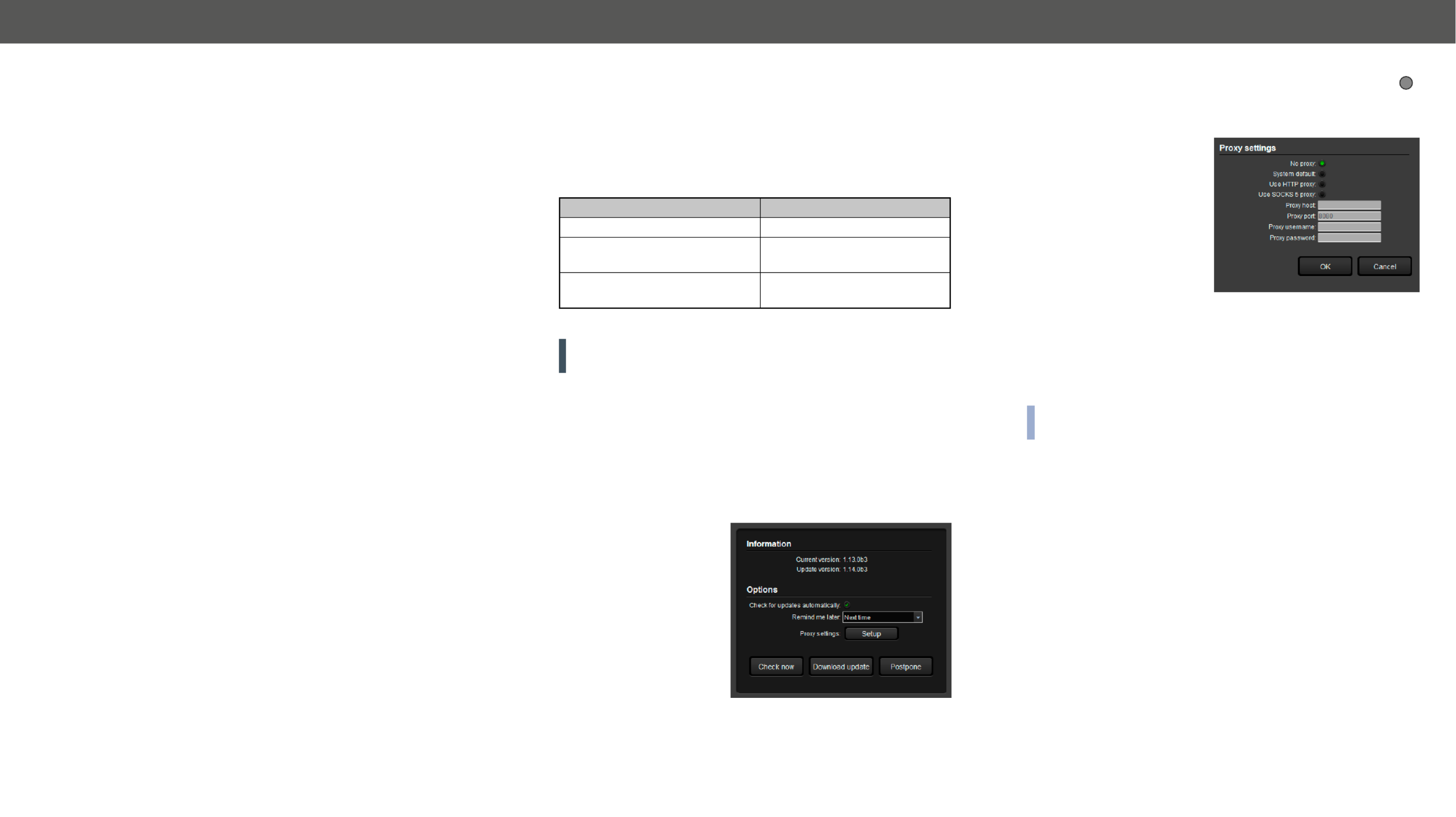
Upgrading of LDC
Step 1. Run the application.
The Device Discovery window
appears automatically
and the program checks
the available updates on
Lightware’s website and
opens the update window if
the LDC found updates.
The current and the update
version number can be seen
at the top of the window
and they are shown in
this window even with the
snapshot install.
The Update window can also be opened by clicking the About icon
and the button.Update
Set the desired update setting in the section.Options
▪If you do not want to
check for the updates
automatically, uncheck
the circle, which contains
the green tick.
▪If you want to postpone
the update, a reminder
can be set with different
delays from the drop
down list.
▪If the proxy settings traverse the update process, set the proper
values then click the button.OK
Step 2. Download updateClick the button to start the upgrading.
The updates can be checked manually by clicking the Check now
button.
has the same look and functionality.
?
5. Software Control - Using Lightware Device Controller HDMI-OPT series – User's Manual 20
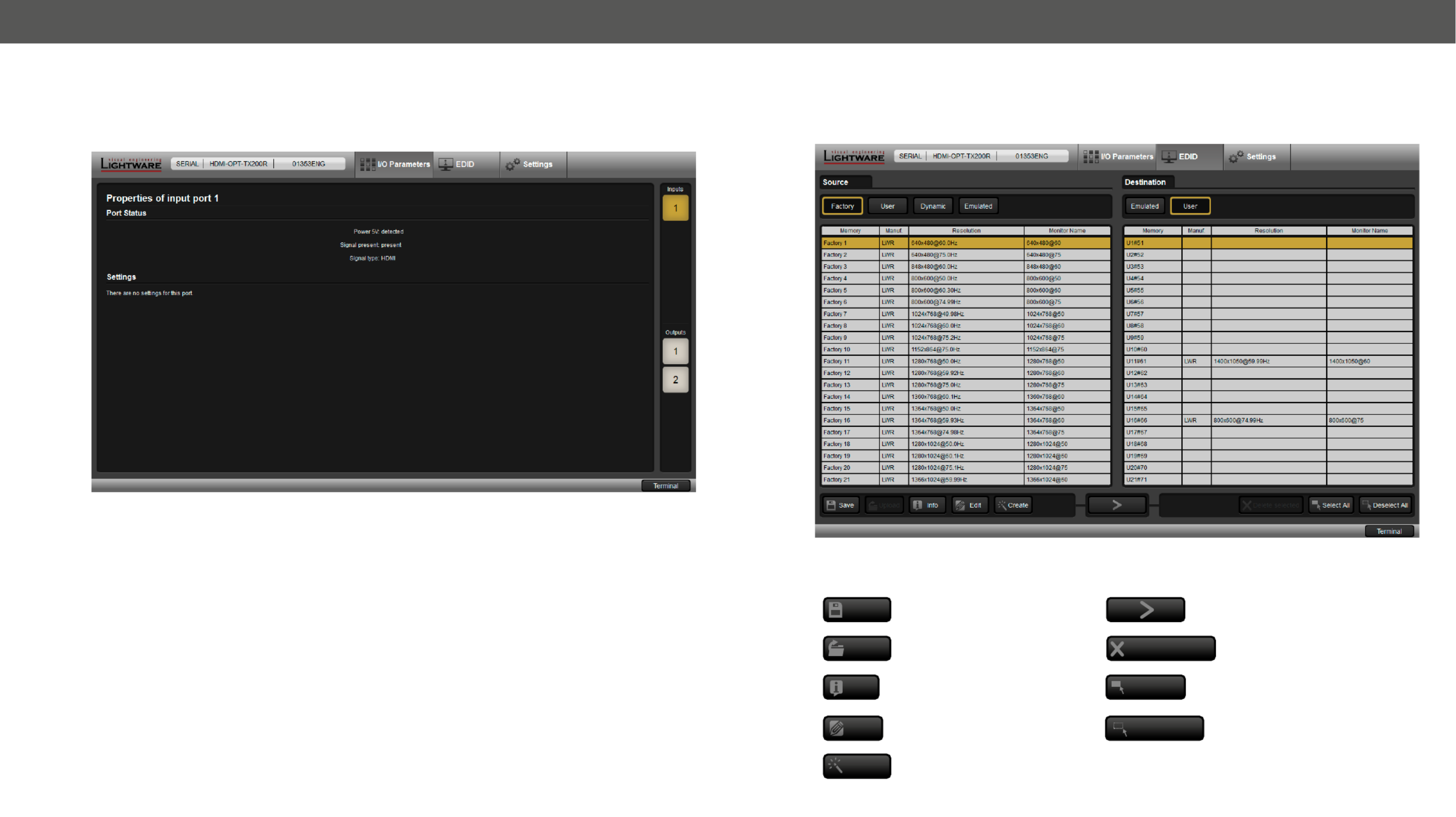
5.3. I/O Parameters Menu
The menu displays the current state of the device. The input port of the device is on the right top, the output
ports are on the right bottom side. The properties of input port is displayed as default.
I/O Parameters menu
5.4. EDID Menu
Advanced EDID Management can be accessed by selecting the EDID menu. There are two panels: left one
contains Source EDIDs, right one contains Destination places where the EDIDs can be emulated or copied.
EDID Menu
Control Buttons
Save Exporting an EDID (save to a le) Executing EDID emulation or
copying (Transfer button)
Upload Importing an EDID (load from
a le) Delete selected Deleting EDID (from User
memory)
Info Display EDID Summary window Select All Selecting all memory places in
the right panel
Edit Opening Advanced EDID Editor
with the selected EDID Deselect All Selecting none of the memory
places in the right panel
Create Opening Easy EDID Creator

5. Software Control - Using Lightware Device Controller HDMI-OPT series – User's Manual 22
5.4.4. Editing an EDID
Select an EDID from Source panel and press Edit button to display Advanced EDID Editor window. The editor
can read and write all descriptors, which are dened in the standards, including the additional CEA extensions.
Any EDID from the device’s memory or a saved EDID le can be loaded into the editor. The software resolves
the raw EDID and displays it as readable information to the user. All descriptors can be edited, and saved in
an EDID le, or uploaded to the User memory.
EDID Editor Window
5.4.5. Creating an EDID
Since above mentioned Advanced EDID Editor needs more complex knowledge about EDID, Lightware
introduced a wizard-like interface for fast and easy EDID creation. With Easy EDID Creator it is possible to
create custom EDIDs in four simple steps. By clicking on the button below Source panel, Create Easy EDID
Creator is opened in a new window.
Easy EDID Creator Window
Specyfikacje produktu
| Marka: | Lightware |
| Kategoria: | przedłużacz AV |
| Model: | HDMI-OPT-RX200R |
| Kolor produktu: | Czarny |
| Częstotliwość wejściowa AC: | 50 - 60 Hz |
| Napięcie wejściowe AC: | 100 - 240 V |
| Wysokość produktu: | 26 mm |
| Szerokość produktu: | 100.4 mm |
| Głębokość produktu: | 131.9 mm |
| Technologia łączności: | Przewodowa |
| Certyfikaty: | CE |
| Gniazdko wyjścia DC: | Tak |
| Zasilacz sieciowy: | Tak |
| Napięcie pracy: | 5 V |
| Diody LED: | Tak |
| Model: | Amplituner |
| Prąd wyjściowy: | 1 A |
| Adapter zewnętrznego zasilania: | Tak |
| Maks. rozdzielczość: | 2048 x 1080 px |
| Wersja HDMI: | 1.3 |
| HDCP: | Tak |
| Szerokość pasma: | 2.25 Gbit/s |
| Materiały: | Metal |
| Złącze światłowodowe: | SC |
| Maksymalny dystans transferu: | 2500 m |
| Obsługiwane rozdzielczości grafiki: | 1920 x 1200 (WUXGA), 2048 x 1080 |
| Głębia kolorów: | 36 bit |
| Struktura światłowódu jednomodowego: | Multifunkcyjny |
| Rozszerzone dane identyfikacyjne wyświetlacza (EDID): | Tak |
| Porty wyjściowe RS-232: | 1 |
| Zużycie prądu (odbiornik) (max): | 9 mA |
| Obsługiwane długości fal światłowodu: | 778,800,825,850,980 nm |
| Przejście HDCP: | Tak |
| Przejście RS-232: | Tak |
| Budżet strat optycznych: | 8 dB |
| Czułość odbiornika OMA: | -14.25 dBm |
| Pobór mocy (RX): | 4 W |
| Przedni panel kontrolny (RX): | Tak |
Potrzebujesz pomocy?
Jeśli potrzebujesz pomocy z Lightware HDMI-OPT-RX200R, zadaj pytanie poniżej, a inni użytkownicy Ci odpowiedzą
Instrukcje przedłużacz AV Lightware

25 Września 2024
25 Września 2024
25 Września 2024
9 Września 2024
9 Września 2024
9 Września 2024
9 Września 2024
9 Września 2024
9 Września 2024
9 Września 2024
Instrukcje przedłużacz AV
- przedłużacz AV Philips
- przedłużacz AV Gigabyte
- przedłużacz AV Roland
- przedłużacz AV KEF
- przedłużacz AV StarTech.com
- przedłużacz AV Crestron
- przedłużacz AV Nedis
- przedłużacz AV AG Neovo
- przedłużacz AV D-Link
- przedłużacz AV ATen
- przedłużacz AV Manhattan
- przedłużacz AV Tripp Lite
- przedłużacz AV Dynaudio
- przedłużacz AV Lindy
- przedłużacz AV LogiLink
- przedłużacz AV Digitus
- przedłużacz AV Oehlbach
- przedłużacz AV AVMATRIX
- przedłużacz AV Renkforce
- przedłużacz AV Adder
- przedłużacz AV DataVideo
- przedłużacz AV One For All
- przedłużacz AV Black Box
- przedłużacz AV Pyle
- przedłużacz AV Iogear
- przedłużacz AV Intellinet
- przedłużacz AV Vivotek
- przedłużacz AV Peerless-AV
- przedłużacz AV Audio Pro
- przedłużacz AV Kindermann
- przedłużacz AV Bogen
- przedłużacz AV Edimax
- przedłużacz AV Planet
- przedłużacz AV Blustream
- przedłużacz AV LevelOne
- przedłużacz AV Vivolink
- przedłużacz AV Teufel
- przedłużacz AV Vision
- przedłużacz AV Abus
- przedłużacz AV Rocstor
- przedłużacz AV Hama
- przedłużacz AV Marmitek
- przedłużacz AV Smart-AVI
- przedłużacz AV Schwaiger
- przedłużacz AV Micro Connect
- przedłużacz AV Allnet
- przedłużacz AV Marshall Electronics
- przedłużacz AV AJA
- przedłużacz AV Trevi
- przedłużacz AV Atlona
- przedłużacz AV Gefen
- przedłużacz AV SEADA
- przedłużacz AV Monacor
- przedłużacz AV I3-Technologies
- przedłużacz AV Alfatron
- przedłużacz AV Megasat
- przedłużacz AV Speaka
- przedłużacz AV Belkin
- przedłużacz AV SWIT
- przedłużacz AV Sescom
- przedłużacz AV Kramer
- przedłużacz AV KanexPro
- przedłużacz AV Kopul
- przedłużacz AV Analog Way
- przedłużacz AV Apantac
- przedłużacz AV AMX
- przedłużacz AV C2G
- przedłużacz AV Act
- przedłużacz AV Eminent
- przedłużacz AV Techly
- przedłużacz AV Matrox
- przedłużacz AV Steren
- przedłużacz AV InFocus
- przedłużacz AV Konig
- przedłużacz AV Dune
- przedłużacz AV Genexis
- przedłużacz AV Wentronic
- przedłużacz AV Peerless
- przedłużacz AV Monoprice
- przedłużacz AV WyreStorm
- przedłużacz AV TV One
- przedłużacz AV MIPRO
- przedłużacz AV Provision ISR
- przedłużacz AV UTEPO
- przedłużacz AV Aitech
- przedłużacz AV SIIG
- przedłużacz AV Polycom
- przedłużacz AV Advantech
- przedłużacz AV Intelix
- przedłużacz AV MuxLab
- przedłużacz AV Extron
- przedłużacz AV ASSMANN Electronic
- przedłużacz AV Avocent
- przedłużacz AV Comprehensive
- przedłużacz AV Rose
- przedłużacz AV Ebode
- przedłużacz AV Accell
- przedłużacz AV Ecler
- przedłużacz AV Rose Electronics
- przedłużacz AV Epcom
- przedłużacz AV CYP
- przedłużacz AV SmartAVI
- przedłużacz AV IMG Stage Line
- przedłużacz AV HELGI
- przedłużacz AV Liberty
- przedłużacz AV PureTools
- przedłużacz AV Enson
- przedłużacz AV Approx
- przedłużacz AV Hall Research
- przedłużacz AV Seco-Larm
- przedłużacz AV ConnectPro
- przedłużacz AV Kanex
- przedłużacz AV TechLogix Networx
- przedłużacz AV PureLink
- przedłużacz AV DVDO
- przedłużacz AV Camplex
Najnowsze instrukcje dla przedłużacz AV
8 Kwietnia 2025
1 Kwietnia 2025
1 Kwietnia 2025
1 Kwietnia 2025
1 Kwietnia 2025
1 Kwietnia 2025
26 Lutego 2025
20 Lutego 2025
20 Lutego 2025
7 Lutego 2025