Instrukcja obsługi Intel SC5400
Intel
nieskategoryzowany
SC5400
Przeczytaj poniżej 📖 instrukcję obsługi w języku polskim dla Intel SC5400 (146 stron) w kategorii nieskategoryzowany. Ta instrukcja była pomocna dla 14 osób i została oceniona przez 2 użytkowników na średnio 4.5 gwiazdek
Strona 1/146


Read all caution and safety statements in this document before performing any of the
instructions. See also Intel Server Boards and Server Chassis Safety Information on the
Intel® Server Deployment Toolkit CD and/or at http://support.intel.com/support/
motherboards/server/sb/cs-010770.htm.
Lesen Sie zunächst sämtliche Warnund Sicherheitshinweise in diesem Dokument, bevor
Sie eine der Anweisungen ausführen. Beachten Sie hierzu auch die Sicherheitshinweise zu
Intel-Serverplatinen und Servergehäusen auf der Intel® Server Deployment Toolkit CD
oder unter http://support.intel.com/support/motherboards/server/sb/cs-010770.htm.
Lisez attention toutes les consignes de sécurité et les mises en garde indiquées dans ce
document avant de suivre toute instruction. Consultez Intel Server Boards and Server
Chassis Safety Information sur le Intel® Server Deployment Toolkit CD ou bien rendez-
vous sur le site http://support.intel.com/support/motherboards/server/sb/cs-010770.htm.
Lea todas las declaraciones de seguridad y precaución de este documento antes de realizar
cualquiera de las instrucciones. Vea Intel Server Boards and Server Chassis Safety
Information en el Intel® Server Deployment Toolkit CD y/o en http://support.intel.com/
support/motherboards/server/sb/cs-010770.htm.

Installing or removing jumpers: A jumper is a small plastic encased conductor that slips
over two jumper pins. Some jumpers have a small tab on top that you can grip with your
fingertips or with a pair of fine needle nosed pliers. If your jumpers do not have such a
tab, take care when using needle nosed pliers to remove or install a jumper; grip the
narrow sides of the jumper with the pliers, never the wide sides. Gripping the wide sides
can damage the contacts inside the jumper, causing intermittent problems with the
function controlled by that jumper. Take care to grip with, but not squeeze, the pliers or
other tool you use to remove a jumper, or you may bend or break the pins on the board.

Thank you for purchasing and using the Intel® Server Chassis SC5400.
This manual is written for system technicians who are responsible for troubleshooting,
upgrading, and repairing this server chassis. This document provides a brief overview of
the features of the chassis, a list of accessories or other components you may need,
troubleshooting information, and instructions on how to add and replace components on
the Intel® Server Chassis SC5400. For the latest version of this manual, see http://
support.intel.com/support/motherboards/server/chassis/SC5400/.
Chapter 1 provides a brief overview of the Intel® Server Chassis SC5400. In this chapter,
you will find a list of the server chassis features, photos of the product, and product
diagrams to help you identify components and their locations.
Chapter 2 provides instructions on adding and replacing components. Use this chapter for
step-by-step instructions and diagrams for installing or replacing components such as the
fans, power supply, drives, and other components.
Chapter 3 provides technical reference information on cable routing, power supply
specifications, and system environment requirements.
At the back of this document, you will find appendices on safety, regulatory, "getting
help", and warranty information.

This server chassis is compatible with the following Intel® Server Boards:
•Intel® Server Board S5000PSL
•Intel® Server Board S5000XVN
Your Intel® Server Chassis SC5400 ships with the following items:
•670W or 830W power supply, installed in the chassis
•A box of hardware components, referred to below as the "chassis hardware box"
•Fan cables, installed in the Intel® Server Chassis SC5400 with product code
SC5400LX or SC5400LXi
•Chassis intrusion switch, installed in the chassis
•Attention document, in the chassis product box
•Intel® Server Chassis SC5400 Quick Start User's Guide, in the chassis hardware box
•Six 32-6mm flat screws for installing drive component, in the chassis hardware box
•Seven screws for mounting the server board into the chassis, in the chassis hardware
box
•USB cable, in the chassis hardware box
•COM2 cable, in the hardware box
In addition, you may need or want to purchase one or more of the following accessory
items for your server: Processor, memory DIMMs, hard drive, floppy drive, CD-ROM or
DVD-ROM drive, RAID controller, operating system.
For information about which accessories, memory, processors, and third-party hardware
have been tested and can be used with your board, and for ordering information for Intel
products, see http://support.intel.com/support/motherboards/server/chassis/SC5400/
compat.htm.

If you need more information about this product or information about the accessories that
can be used with this server chassis, use the following resources. These files are available
at http://support.intel.com/support/motherboards/server/chassis/SC5400/.
Unless otherwise indicated in the table below, once on this Web page, type the document
or software name in the search field at the left side of the screen and select the option to
search "This Product."


This chapter briefly describes the main features of the Intel
® Server Chassis SC5400. This
chapter provides a list of the server chassis features, as well as diagrams showing the
location of important components and connections on the server chassis.
AF000551

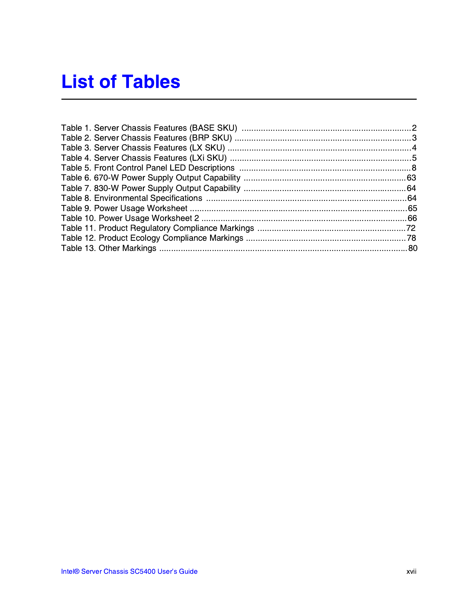
Table 1 summarizes the features of the Intel
® Server Chassis SC5400 Base SKU
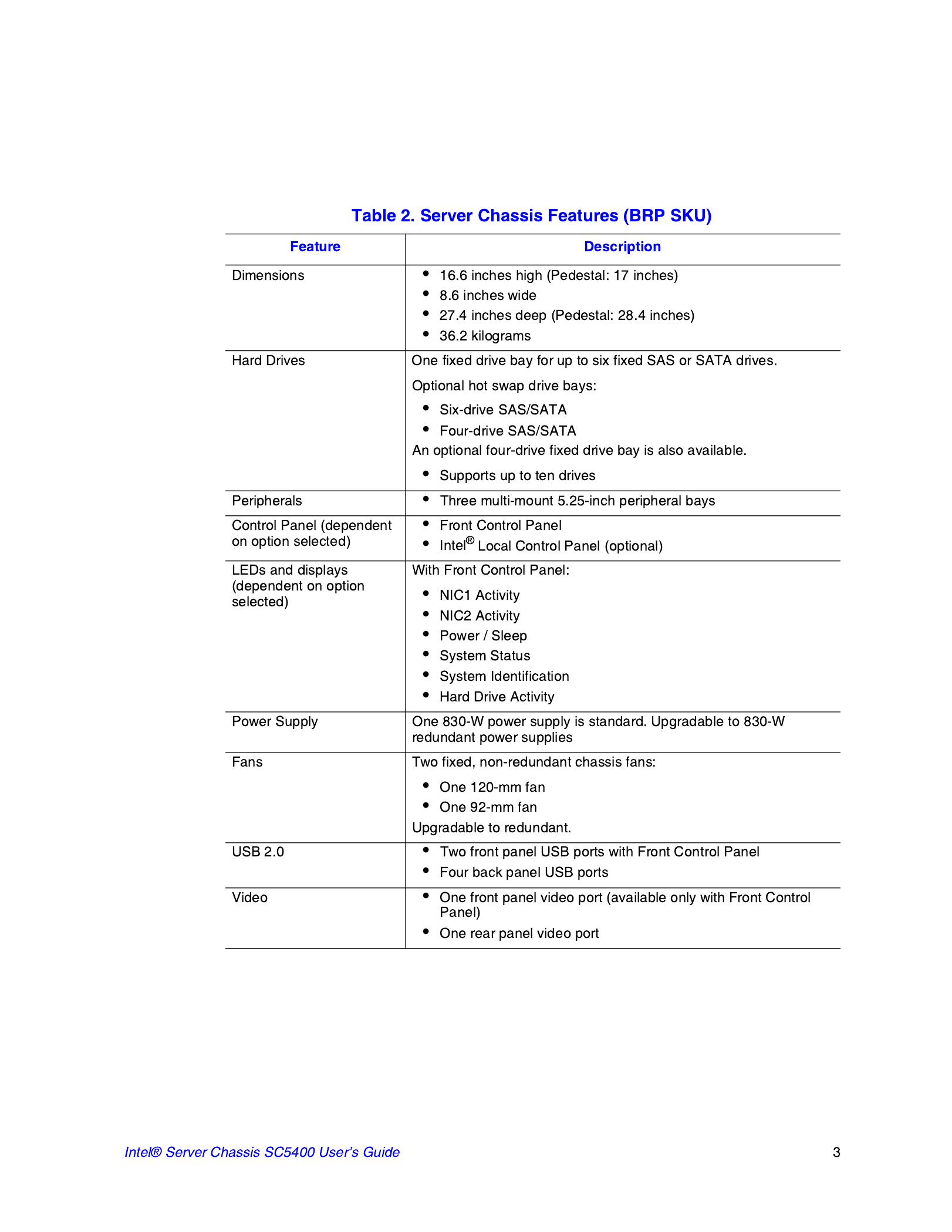
Table 2 summarizes the features of the BRP SKU.

Table 3 summarizes the features of the LX SKU.

Table 3 summarizes the features of the SC5400LXi SKU

A
C
B
F
L
G
H
K
E
D
J
I
AF000511

The following figure shows the features available on the Front Control Panel. The Intel
®
Local Control Panel is optional.
TP00701
A
B
C
E
F
G
H
I
D

Descriptions of the front control panel LEDs are listed in the following table. See your
server documentation for functionality of buttons.
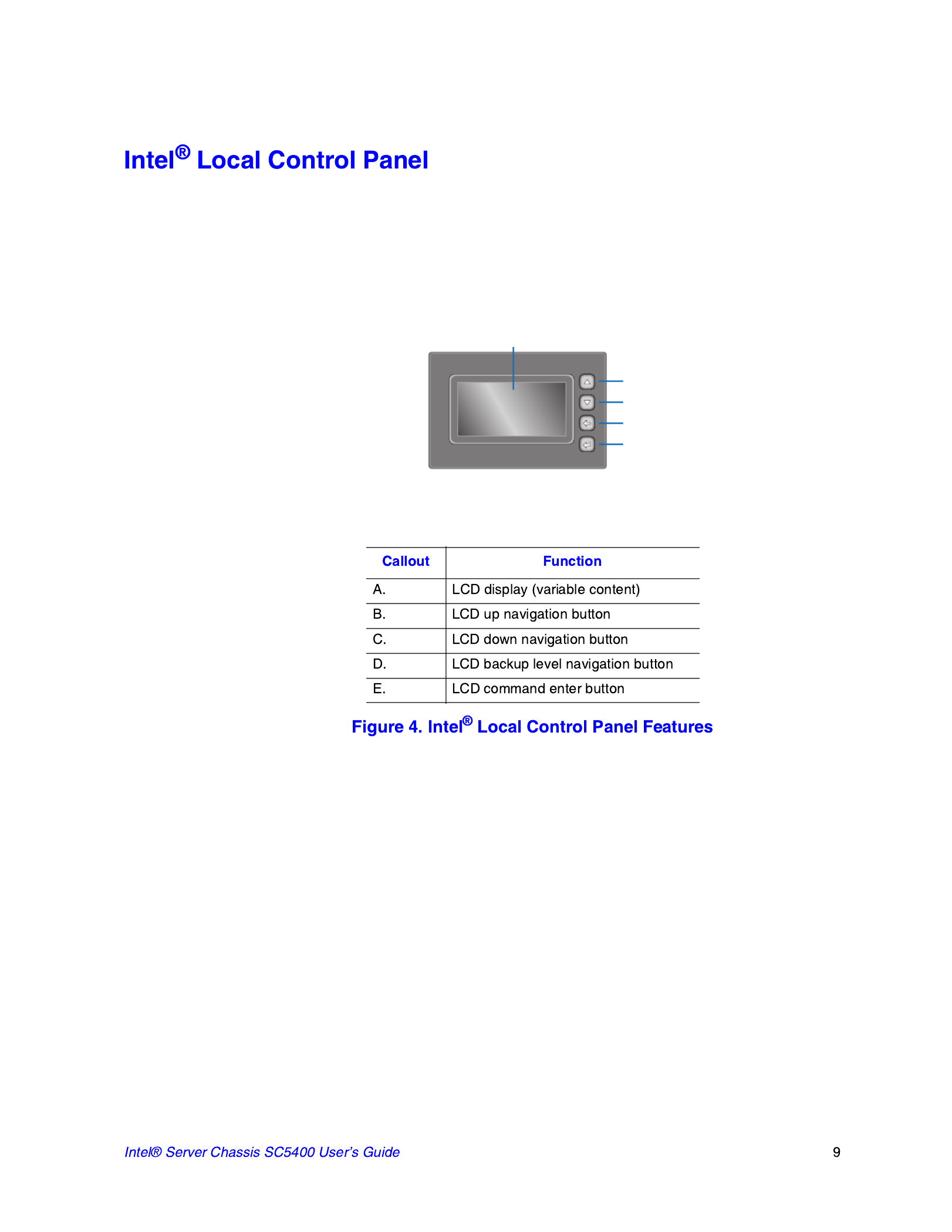
The following figure shows the features available on the Intel® Local Control Panel. The
Intel® Local Control Panel is optional.
Note: The Intel® Local Control Panel requires the installation of the Intel
® Remote
Management Module. See your server board documentation to determine if this control
panel is compatible with your server board.
AF000955
A
B
C
D
E

Note: I/O connectors vary, depending on the server board installed. See your server board
documentation for port identification.
TP00526
A
B
CD
E
F
G

The chassis provides locations and hardware for installing hard drives, a floppy drive, a
CD-ROM drive, or a DVD-ROM drive. The drives must be purchased separately. The
following figure shows the available options.
A
C
B
AF000552


Before working with your server product, pay close attention to the “Safety Information”
on page iii.
This document provides instructions for adding and replacing chassis components. For
instructions on replacing components on the server board, such as the processor and
memory DIMMs, see the instructions provided with the server board.
•Phillips* (cross head) screwdriver (#1 bit and #2 bit)
•Needle nosed pliers
•Anti-static wrist strap and conductive foam pad (recommended)
All references to left, right, front, top, and bottom assume the reader is facing the front of
the chassis as it would be positioned for normal operation.

The Intel® Server Chassis SC5400 must be operated with the top cover in place to ensure
proper cooling. You will need to remove the top cover to add or replace components
inside of the platform. Before removing the top cover, power down the server and unplug
all peripheral devices and the AC power cable.
Note: A non-skid surface or a stop behind the chassis may be needed to prevent the chassis from
sliding on your work surface.
1. Observe the safety and ESD precautions at the beginning of this book. See “Safety
Information” on page iii.
2. Turn off all peripheral devices connected to the server. Turn off the server.
3. Disconnect the AC power cord.
4. Remove the access cover screw if it is installed (see letter "A" in the following
figure). While holding in the blue button at the top of the chassis (see letter "B"),
slide the top cover back until it stops. Lift the cover outward to remove it.
AF000555
A
B
A
B

1. Slide the chassis cover on the chassis.
2. Latch the cover securely to the chassis.
3. If the chassis will be re-shipped, secure the chassis cover to the chassis with the
access cover screw (see letter “A” in the following figure).
AF000572
A
A

Caution: Do not rotate the bezel assembly more than 40 degrees or you will damage the bezel
assembly.
Note: The bezel assembly consists of two components, a front door and a sub-bezel.
1. Observe the safety and ESD precautions at the beginning of this book.
2. Power down the server and unplug all peripheral devices and the AC power cable.
3. Remove the chassis cover. For instructions, see “Removing the Chassis Cover” on
page 16.
4. Release the two plastic tabs (see letter “A” in the following figure) on the left side
of the bezel assembly to disengage the tabs.
5. Rotate the bezel assembly (see letter “B”) no more than 40 degrees outward.
6. At a 40-degree angle, push the bezel assembly away from the chassis (see letter
“C”).
7. If the bezel assembly does not immediately disconnect from the chassis, tap the
left-hand side of the bezel assembly to disengage the bezel hooks on the right-hand
side of the chassis.
AF000557
A
A
B
C

1. Observe the safety and ESD precautions at the beginning of this book.
2. Power down the server and unplug all peripheral devices and the AC power cable.
3. Remove the chassis cover. For instructions, see “Removing the Chassis Cover” on
page 16.
4. Remove the front bezel if it is installed. For instructions, see “Removing and
Installing the Front Bezel” on page 18.
5. Remove an EMI shield/slide assembly from the upper device bay by pressing the
two slide assembly latches inward (see letter “A” in the following figure). Remove
the slides from the EMI shield by pulling the slides away from the EMI shield to
release them from the EMI shield (see letter “B”).
6. Attach slides to the DVD or CD-ROM drive by pressing the slides firmly into the
side dimples on the DVD or CD-ROM drive.
AF000945
A
AB
B
AF000576
Specyfikacje produktu
| Marka: | Intel |
| Kategoria: | nieskategoryzowany |
| Model: | SC5400 |
| Kolor produktu: | Czarny |
| Typ produktu: | 14 |
| Wysokość produktu: | 445 mm |
| Szerokość produktu: | 218 mm |
| Głębokość produktu: | 683 mm |
| Układ: | Full Tower |
| Kod zharmonizowanego systemu (HS): | 8473305100 |
| Liczba portów USB 2.0: | 2 |
| Model: | Serwer |
| Ilość obsługiwanych rozmiarów dysków pamięci: | 10 |
| Obudowa: | Pedestal, 5U Rack Option |
| Zasilanie: | 670 W |
| Typ zasilacza: | Prąd przemienny |
| Możliwości montowania w stelażu: | Tak |
| Zautomatyzowany system śledzenia klasyfikacji towarów (CCATS): | G135162 |
| Pojemność stelaża: | 5U |
| Zawartość opakowania: | (6) Drive carriers; (1) Front panel cable; (1) Non-redundant 670W power supply; (2) Non-redundant cooling fans; (1) USB cable; (1) Pre-routed IDE cable; (1) COM2 cable |
| Ilość zatok 3.5": | 10 |
| Maksymalna konfiguracja CPU: | 2 |
| Szeregowe porty komunikacyjne: | 1 |
| Numer klasyfikacji kontroli eksportu (ECCN): | 5A992C |
| Segment rynku: | Serwer |
| Status: | End of Life |
| Rodzina produktów: | Serwer Legacy/ obudowa stacji roboczej |
| Ostatnia zmiana: | 63903513 |
| Data premiery: | Q2'06 |
| Seria produktów: | Intel SC5400 |
| Nazwa kodowa produktu: | Riggins |
| Obsługa 3.5 " HDD: | Support for up to ten (6+4) fixed or hot-swap SAS/SATA drives |
| Przewidywany termin dyskontynuacji: | Q2'10 |
| Rynek docelowy: | Small and Medium Business |
| Ogłoszenie daty końca życia: | 2010-04-30T00:00:00 |
| Data ostatniego zamówienia: | 2010-10-31T00:00:00 |
| Data ostatniego potwierdzenia atrybutu: | 2011-02-28T00:00:00 |
| ARK ID: | 23560 |
| Obsługiwane formaty dysków pamięci masowej: | Hot-swap 2.5 or 3.5 |
Potrzebujesz pomocy?
Jeśli potrzebujesz pomocy z Intel SC5400, zadaj pytanie poniżej, a inni użytkownicy Ci odpowiedzą
Instrukcje nieskategoryzowany Intel

14 Września 2024
14 Września 2024
14 Września 2024
Instrukcje nieskategoryzowany
- nieskategoryzowany Sony
- nieskategoryzowany Bauknecht
- nieskategoryzowany Yamaha
- nieskategoryzowany Ikea
- nieskategoryzowany Hoshizaki
- nieskategoryzowany Samsung
- nieskategoryzowany Tesy
- nieskategoryzowany PeakTech
- nieskategoryzowany Bertazzoni
- nieskategoryzowany Electrolux
- nieskategoryzowany Gamdias
- nieskategoryzowany Tenda
- nieskategoryzowany DeLonghi
- nieskategoryzowany AEG
- nieskategoryzowany Fellowes
- nieskategoryzowany Balay
- nieskategoryzowany Leica
- nieskategoryzowany Beko
- nieskategoryzowany Teka
- nieskategoryzowany Sven
- nieskategoryzowany ChamSys
- nieskategoryzowany LG
- nieskategoryzowany Worx
- nieskategoryzowany Küppersbusch
- nieskategoryzowany Smeg
- nieskategoryzowany Motorola
- nieskategoryzowany Götze & Jensen
- nieskategoryzowany Dreame
- nieskategoryzowany Beurer
- nieskategoryzowany Stabo
- nieskategoryzowany Logitech
- nieskategoryzowany Gram
- nieskategoryzowany Spektrum
- nieskategoryzowany Xiaomi
- nieskategoryzowany Gorenje
- nieskategoryzowany Etna
- nieskategoryzowany Joy-It
- nieskategoryzowany LERAN
- nieskategoryzowany President
- nieskategoryzowany MyPhone
- nieskategoryzowany Sharp
- nieskategoryzowany BeamZ
- nieskategoryzowany Huawei
- nieskategoryzowany Supermicro
- nieskategoryzowany TCL
- nieskategoryzowany Braun
- nieskategoryzowany Russell Hobbs
- nieskategoryzowany Pioneer
- nieskategoryzowany Statron
- nieskategoryzowany Sage
- nieskategoryzowany Lenovo
- nieskategoryzowany Tefal
- nieskategoryzowany Honda
- nieskategoryzowany TP-Link
- nieskategoryzowany Voltcraft
- nieskategoryzowany Milwaukee
- nieskategoryzowany Philips
- nieskategoryzowany Livoo
- nieskategoryzowany SilverCrest
- nieskategoryzowany Simpson
- nieskategoryzowany Dometic
- nieskategoryzowany Gigabyte
- nieskategoryzowany Acer
- nieskategoryzowany Realme
- nieskategoryzowany Ultimate Speed
- nieskategoryzowany Stihl
- nieskategoryzowany Bosch
- nieskategoryzowany Yato
- nieskategoryzowany Xblitz
- nieskategoryzowany Epson
- nieskategoryzowany JBL
- nieskategoryzowany Parkside
- nieskategoryzowany Hikvision
- nieskategoryzowany Candy
- nieskategoryzowany GW Instek
- nieskategoryzowany Onkyo
- nieskategoryzowany Whirlpool
- nieskategoryzowany Grillmeister
- nieskategoryzowany IPGARD
- nieskategoryzowany Fujitsu
- nieskategoryzowany Ferroli
- nieskategoryzowany Thule
- nieskategoryzowany Roland
- nieskategoryzowany Miele
- nieskategoryzowany HyperX
- nieskategoryzowany Easy Home
- nieskategoryzowany LC-Power
- nieskategoryzowany Waterco
- nieskategoryzowany Geemarc
- nieskategoryzowany Scott
- nieskategoryzowany Brentwood
- nieskategoryzowany Midea
- nieskategoryzowany KEF
- nieskategoryzowany Festool
- nieskategoryzowany Kärcher
- nieskategoryzowany Bose
- nieskategoryzowany Severin
- nieskategoryzowany Hisense
- nieskategoryzowany Berg
- nieskategoryzowany Infiniton
- nieskategoryzowany EZVIZ
- nieskategoryzowany Conceptronic
- nieskategoryzowany Panasonic
- nieskategoryzowany StarTech.com
- nieskategoryzowany Promethean
- nieskategoryzowany Bavaria By Einhell
- nieskategoryzowany Theben
- nieskategoryzowany Liebherr
- nieskategoryzowany Canon
- nieskategoryzowany Mio
- nieskategoryzowany Crestron
- nieskategoryzowany Truetone
- nieskategoryzowany Bestway
- nieskategoryzowany Viewsonic
- nieskategoryzowany Behringer
- nieskategoryzowany Asus
- nieskategoryzowany Nedis
- nieskategoryzowany Stanley
- nieskategoryzowany Nexa
- nieskategoryzowany Jura
- nieskategoryzowany AG Neovo
- nieskategoryzowany Be Cool
- nieskategoryzowany Allen & Heath
- nieskategoryzowany Enphase
- nieskategoryzowany IK Multimedia
- nieskategoryzowany Reolink
- nieskategoryzowany American DJ
- nieskategoryzowany Medion
- nieskategoryzowany Tangent
- nieskategoryzowany Boss
- nieskategoryzowany Black & Decker
- nieskategoryzowany OK
- nieskategoryzowany Lenco
- nieskategoryzowany TRENDnet
- nieskategoryzowany Audioline
- nieskategoryzowany Max Pro
- nieskategoryzowany Scheppach
- nieskategoryzowany Fujifilm
- nieskategoryzowany Proxxon
- nieskategoryzowany Adler
- nieskategoryzowany Bluetti
- nieskategoryzowany BaByliss
- nieskategoryzowany Marquant
- nieskategoryzowany Subaru
- nieskategoryzowany MSI
- nieskategoryzowany Hoover
- nieskategoryzowany Tesla
- nieskategoryzowany Westinghouse
- nieskategoryzowany D-Link
- nieskategoryzowany Hendi
- nieskategoryzowany Jensen
- nieskategoryzowany Niceboy
- nieskategoryzowany Hazet
- nieskategoryzowany Vertiv
- nieskategoryzowany Conair
- nieskategoryzowany GE
- nieskategoryzowany ILive
- nieskategoryzowany Ardes
- nieskategoryzowany Taurus
- nieskategoryzowany VitalMaxx
- nieskategoryzowany RIKON
- nieskategoryzowany Ring
- nieskategoryzowany Orbegozo
- nieskategoryzowany Native Instruments
- nieskategoryzowany Garmin
- nieskategoryzowany Blaupunkt
- nieskategoryzowany Vivax
- nieskategoryzowany ATen
- nieskategoryzowany IOptron
- nieskategoryzowany Grizzly
- nieskategoryzowany Salora
- nieskategoryzowany Siemens
- nieskategoryzowany Teac
- nieskategoryzowany Speed-Link
- nieskategoryzowany Casio
- nieskategoryzowany Iiyama
- nieskategoryzowany Lincoln Electric
- nieskategoryzowany Metra
- nieskategoryzowany Thrustmaster
- nieskategoryzowany Evolveo
- nieskategoryzowany Ambiano
- nieskategoryzowany DeWalt
- nieskategoryzowany Bbf
- nieskategoryzowany Danby
- nieskategoryzowany Martin Logan
- nieskategoryzowany Dual
- nieskategoryzowany Einhell
- nieskategoryzowany Grundig
- nieskategoryzowany APC
- nieskategoryzowany Hegel
- nieskategoryzowany Kiloview
- nieskategoryzowany Haier
- nieskategoryzowany Sigma
- nieskategoryzowany Homedics
- nieskategoryzowany Remington
- nieskategoryzowany HP
- nieskategoryzowany KKT Kolbe
- nieskategoryzowany Cylinda
- nieskategoryzowany S.M.S.L
- nieskategoryzowany Genesis
- nieskategoryzowany Jocel
- nieskategoryzowany Soundmaster
- nieskategoryzowany Hyundai
- nieskategoryzowany Silverline
- nieskategoryzowany Blomberg
- nieskategoryzowany Line 6
- nieskategoryzowany Husqvarna
- nieskategoryzowany Honeywell
- nieskategoryzowany BLOW
- nieskategoryzowany DAP-Audio
- nieskategoryzowany Concept
- nieskategoryzowany Joie
- nieskategoryzowany Manhattan
- nieskategoryzowany Chauvet
- nieskategoryzowany Microchip
- nieskategoryzowany Heritage Audio
- nieskategoryzowany Fisher & Paykel
- nieskategoryzowany Angelcare
- nieskategoryzowany Cotek
- nieskategoryzowany Durvet
- nieskategoryzowany Tripp Lite
- nieskategoryzowany Shure
- nieskategoryzowany EWON
- nieskategoryzowany ECG
- nieskategoryzowany IRobot
- nieskategoryzowany Indesit
- nieskategoryzowany Matsui
- nieskategoryzowany Amazfit
- nieskategoryzowany Steinel
- nieskategoryzowany Makita
- nieskategoryzowany Ilve
- nieskategoryzowany Mikrotik
- nieskategoryzowany Denon
- nieskategoryzowany Akasa
- nieskategoryzowany Perkins
- nieskategoryzowany Swann
- nieskategoryzowany Truma
- nieskategoryzowany Kwikset
- nieskategoryzowany Mercury
- nieskategoryzowany Empress Effects
- nieskategoryzowany Carel
- nieskategoryzowany Nikon
- nieskategoryzowany Shimano
- nieskategoryzowany Viking
- nieskategoryzowany Antari
- nieskategoryzowany Medela
- nieskategoryzowany Block
- nieskategoryzowany Ozito
- nieskategoryzowany Kodak
- nieskategoryzowany Phoenix Gold
- nieskategoryzowany Forza
- nieskategoryzowany CATA
- nieskategoryzowany Testo
- nieskategoryzowany Audac
- nieskategoryzowany Cisco
- nieskategoryzowany Revic
- nieskategoryzowany Primera
- nieskategoryzowany Draper
- nieskategoryzowany Aim TTi
- nieskategoryzowany Fuxtec
- nieskategoryzowany ORNO
- nieskategoryzowany Cooler Master
- nieskategoryzowany Sanus
- nieskategoryzowany TFA
- nieskategoryzowany Dyson
- nieskategoryzowany Chauvin Arnoux
- nieskategoryzowany Hotpoint
- nieskategoryzowany Kenwood
- nieskategoryzowany Scosche
- nieskategoryzowany Icy Box
- nieskategoryzowany Sungrow
- nieskategoryzowany NuPrime
- nieskategoryzowany Hasbro
- nieskategoryzowany Moxa
- nieskategoryzowany Trisa
- nieskategoryzowany DJI
- nieskategoryzowany RYOBI
- nieskategoryzowany Kugoo
- nieskategoryzowany Alpine
- nieskategoryzowany Wolf Garten
- nieskategoryzowany Knog
- nieskategoryzowany Gembird
- nieskategoryzowany Scala
- nieskategoryzowany ZTE
- nieskategoryzowany Godox
- nieskategoryzowany Røde
- nieskategoryzowany Zelmer
- nieskategoryzowany Hammersmith
- nieskategoryzowany Chicco
- nieskategoryzowany Chamberlain
- nieskategoryzowany Paradigm
- nieskategoryzowany Lindy
- nieskategoryzowany Olivetti
- nieskategoryzowany Ninja
- nieskategoryzowany Medisana
- nieskategoryzowany Minox
- nieskategoryzowany Cuisinart
- nieskategoryzowany Zebra
- nieskategoryzowany Wilfa
- nieskategoryzowany DSC
- nieskategoryzowany Cobra
- nieskategoryzowany JVC
- nieskategoryzowany ZyXEL
- nieskategoryzowany Auriol
- nieskategoryzowany Konig & Meyer
- nieskategoryzowany Trust
- nieskategoryzowany BLUEPALM
- nieskategoryzowany V7
- nieskategoryzowany Thor
- nieskategoryzowany LogiLink
- nieskategoryzowany Handy
- nieskategoryzowany Memphis Audio
- nieskategoryzowany Sandisk
- nieskategoryzowany Grohe
- nieskategoryzowany Dell
- nieskategoryzowany Polaris
- nieskategoryzowany GLORIA
- nieskategoryzowany IFM
- nieskategoryzowany Krups
- nieskategoryzowany Furrion
- nieskategoryzowany U-Line
- nieskategoryzowany Linksys
- nieskategoryzowany Moulinex
- nieskategoryzowany Cleanmaxx
- nieskategoryzowany Ursus Trotter
- nieskategoryzowany DEDRA
- nieskategoryzowany Corsair
- nieskategoryzowany Emerio
- nieskategoryzowany Owon
- nieskategoryzowany Focusrite
- nieskategoryzowany Baumr-AG
- nieskategoryzowany Patriot
- nieskategoryzowany Google
- nieskategoryzowany Create
- nieskategoryzowany Rega
- nieskategoryzowany Intex
- nieskategoryzowany Biltema
- nieskategoryzowany Oricom
- nieskategoryzowany B.E.G.
- nieskategoryzowany H.Koenig
- nieskategoryzowany MyPOS
- nieskategoryzowany CMI
- nieskategoryzowany Hilti
- nieskategoryzowany Steelseries
- nieskategoryzowany Digitus
- nieskategoryzowany Salewa
- nieskategoryzowany Oppo
- nieskategoryzowany Alesis
- nieskategoryzowany Lowrance
- nieskategoryzowany Anybus
- nieskategoryzowany Melissa
- nieskategoryzowany TechniSat
- nieskategoryzowany Vimar
- nieskategoryzowany Nubert
- nieskategoryzowany Dahua Technology
- nieskategoryzowany Schneider
- nieskategoryzowany Deutz
- nieskategoryzowany SABO
- nieskategoryzowany Ledlenser
- nieskategoryzowany Beper
- nieskategoryzowany Eurolite
- nieskategoryzowany LD Systems
- nieskategoryzowany Techno Line
- nieskategoryzowany Foppapedretti
- nieskategoryzowany Daikin
- nieskategoryzowany Kospel
- nieskategoryzowany EVOline
- nieskategoryzowany Kubota
- nieskategoryzowany Thetford
- nieskategoryzowany Oehlbach
- nieskategoryzowany TrueLife
- nieskategoryzowany Eufy
- nieskategoryzowany Ricoh
- nieskategoryzowany TOGU
- nieskategoryzowany SMART Technologies
- nieskategoryzowany NZXT
- nieskategoryzowany Audioengine
- nieskategoryzowany Hozelock
- nieskategoryzowany OneConcept
- nieskategoryzowany CDA
- nieskategoryzowany Emos
- nieskategoryzowany Sabrent
- nieskategoryzowany AVMATRIX
- nieskategoryzowany IMC Toys
- nieskategoryzowany Philco
- nieskategoryzowany Neff
- nieskategoryzowany Seiko
- nieskategoryzowany Renkforce
- nieskategoryzowany Rollei
- nieskategoryzowany Corbero
- nieskategoryzowany Zanussi
- nieskategoryzowany Sonel
- nieskategoryzowany NightStick
- nieskategoryzowany Instant
- nieskategoryzowany Crivit
- nieskategoryzowany Marshall
- nieskategoryzowany Osram
- nieskategoryzowany BaseTech
- nieskategoryzowany Thermex
- nieskategoryzowany Traxxas
- nieskategoryzowany Viessmann
- nieskategoryzowany Perel
- nieskategoryzowany Wagner
- nieskategoryzowany Fagor
- nieskategoryzowany GoldAir
- nieskategoryzowany Sena
- nieskategoryzowany Graco
- nieskategoryzowany Trotec
- nieskategoryzowany Autel
- nieskategoryzowany Uniden
- nieskategoryzowany Adder
- nieskategoryzowany Ansmann
- nieskategoryzowany Clarion
- nieskategoryzowany Netgear
- nieskategoryzowany Cellular Line
- nieskategoryzowany Thomson
- nieskategoryzowany DiO
- nieskategoryzowany Pro-Ject
- nieskategoryzowany Texas Instruments
- nieskategoryzowany Lastolite
- nieskategoryzowany AVM
- nieskategoryzowany La Crosse Technology
- nieskategoryzowany Growatt
- nieskategoryzowany Izzy
- nieskategoryzowany Little Tikes
- nieskategoryzowany Chipolino
- nieskategoryzowany Velleman
- nieskategoryzowany Ferguson
- nieskategoryzowany BT
- nieskategoryzowany Meec Tools
- nieskategoryzowany Fusion
- nieskategoryzowany BOYA
- nieskategoryzowany WMF
- nieskategoryzowany Korg
- nieskategoryzowany ProfiCook
- nieskategoryzowany Homematic IP
- nieskategoryzowany DataVideo
- nieskategoryzowany One For All
- nieskategoryzowany Klarstein
- nieskategoryzowany Safety 1st
- nieskategoryzowany Polti
- nieskategoryzowany Totolink
- nieskategoryzowany Danfoss
- nieskategoryzowany JYSK
- nieskategoryzowany Coyote
- nieskategoryzowany Intertechno
- nieskategoryzowany Black Box
- nieskategoryzowany Lowepro
- nieskategoryzowany Güde
- nieskategoryzowany Arendo
- nieskategoryzowany DreamGEAR
- nieskategoryzowany Victron Energy
- nieskategoryzowany Delta Dore
- nieskategoryzowany E-ast
- nieskategoryzowany Manta
- nieskategoryzowany Pyle
- nieskategoryzowany CTA Digital
- nieskategoryzowany Segway
- nieskategoryzowany Gem Toys
- nieskategoryzowany Texas
- nieskategoryzowany Lancom
- nieskategoryzowany Adviti
- nieskategoryzowany Crimson
- nieskategoryzowany Dymo
- nieskategoryzowany ATIKA
- nieskategoryzowany Hauck
- nieskategoryzowany Iogear
- nieskategoryzowany Cardo
- nieskategoryzowany Panduit
- nieskategoryzowany Intellinet
- nieskategoryzowany NGS
- nieskategoryzowany CRUX
- nieskategoryzowany Newline
- nieskategoryzowany Bavaria
- nieskategoryzowany Devolo
- nieskategoryzowany Juwel
- nieskategoryzowany Biostar
- nieskategoryzowany Dirt Devil
- nieskategoryzowany Midland
- nieskategoryzowany Marantz
- nieskategoryzowany KitchenAid
- nieskategoryzowany MARTOR
- nieskategoryzowany AFK
- nieskategoryzowany AOC
- nieskategoryzowany Monster
- nieskategoryzowany Sennheiser
- nieskategoryzowany EchoMaster
- nieskategoryzowany JANDY
- nieskategoryzowany Esoteric
- nieskategoryzowany Roidmi
- nieskategoryzowany Zipper
- nieskategoryzowany Vivotek
- nieskategoryzowany Eta
- nieskategoryzowany Mount-It!
- nieskategoryzowany Camry
- nieskategoryzowany Steba
- nieskategoryzowany Werma
- nieskategoryzowany Peerless-AV
- nieskategoryzowany Speco Technologies
- nieskategoryzowany Suunto
- nieskategoryzowany Showtec
- nieskategoryzowany Weber
- nieskategoryzowany Heckler Design
- nieskategoryzowany Lenoxx
- nieskategoryzowany Grundfos
- nieskategoryzowany Samson
- nieskategoryzowany EtiamPro
- nieskategoryzowany Faworyt
- nieskategoryzowany EA Elektro Automatik
- nieskategoryzowany Imperial
- nieskategoryzowany Helios
- nieskategoryzowany Scarlett
- nieskategoryzowany Microlife
- nieskategoryzowany PreSonus
- nieskategoryzowany Mercusys
- nieskategoryzowany Koss
- nieskategoryzowany Audio Pro
- nieskategoryzowany I-TEC
- nieskategoryzowany ARRI
- nieskategoryzowany Gossen Metrawatt
- nieskategoryzowany Sôlt
- nieskategoryzowany Eden
- nieskategoryzowany Fosi Audio
- nieskategoryzowany TC Electronic
- nieskategoryzowany Shelly
- nieskategoryzowany Revox
- nieskategoryzowany Fluke
- nieskategoryzowany Nevir
- nieskategoryzowany Kindermann
- nieskategoryzowany Megger
- nieskategoryzowany Kayser
- nieskategoryzowany Olympus
- nieskategoryzowany Navitel
- nieskategoryzowany Greisinger
- nieskategoryzowany MTD
- nieskategoryzowany Oliveri
- nieskategoryzowany Musical Fidelity
- nieskategoryzowany Master Lock
- nieskategoryzowany Bogen
- nieskategoryzowany Pulsar
- nieskategoryzowany PATLITE
- nieskategoryzowany Exquisit
- nieskategoryzowany Bartscher
- nieskategoryzowany Schaudt
- nieskategoryzowany Phanteks
- nieskategoryzowany Hestan
- nieskategoryzowany Gastroback
- nieskategoryzowany GYS
- nieskategoryzowany Mitsubishi
- nieskategoryzowany Edimax
- nieskategoryzowany Razer
- nieskategoryzowany Dimplex
- nieskategoryzowany Florabest
- nieskategoryzowany Harvia
- nieskategoryzowany Baxi
- nieskategoryzowany ADATA
- nieskategoryzowany Kidde
- nieskategoryzowany Chief
- nieskategoryzowany Peavey
- nieskategoryzowany GoClever
- nieskategoryzowany Baby Lock
- nieskategoryzowany Dehner
- nieskategoryzowany ION
- nieskategoryzowany Camille Bauer
- nieskategoryzowany Huion
- nieskategoryzowany Arçelik
- nieskategoryzowany ART
- nieskategoryzowany First Alert
- nieskategoryzowany Assa Abloy
- nieskategoryzowany Solo
- nieskategoryzowany Continental Edison
- nieskategoryzowany RCF
- nieskategoryzowany Topmove
- nieskategoryzowany Delta
- nieskategoryzowany Kerbl
- nieskategoryzowany Zhiyun
- nieskategoryzowany Gree
- nieskategoryzowany Fluval
- nieskategoryzowany Bissell
- nieskategoryzowany Rolls
- nieskategoryzowany Audio-Technica
- nieskategoryzowany Maginon
- nieskategoryzowany EnGenius
- nieskategoryzowany Atag
- nieskategoryzowany Rosieres
- nieskategoryzowany Franke
- nieskategoryzowany Planet
- nieskategoryzowany Adidas
- nieskategoryzowany GoGen
- nieskategoryzowany Accu-Chek
- nieskategoryzowany RCBS
- nieskategoryzowany Peg Perego
- nieskategoryzowany NEC
- nieskategoryzowany Brandson
- nieskategoryzowany Soundcraft
- nieskategoryzowany Parrot
- nieskategoryzowany Antec
- nieskategoryzowany Vornado
- nieskategoryzowany Polaroid
- nieskategoryzowany Rocktrail
- nieskategoryzowany Prestigio
- nieskategoryzowany Aiwa
- nieskategoryzowany G3 Ferrari
- nieskategoryzowany JL Audio
- nieskategoryzowany LevelOne
- nieskategoryzowany Konica Minolta
- nieskategoryzowany AKAI
- nieskategoryzowany Tunturi
- nieskategoryzowany Razor
- nieskategoryzowany Digi
- nieskategoryzowany Mobicool
- nieskategoryzowany Axis
- nieskategoryzowany Deity
- nieskategoryzowany Vivolink
- nieskategoryzowany Westfalia
- nieskategoryzowany Hamilton Beach
- nieskategoryzowany Majority
- nieskategoryzowany Hayward
- nieskategoryzowany Neumärker
- nieskategoryzowany Rigol
- nieskategoryzowany Bixolon
- nieskategoryzowany Ergotools Pattfield
- nieskategoryzowany Novy
- nieskategoryzowany Hartke
- nieskategoryzowany Clatronic
- nieskategoryzowany Healthy Choice
- nieskategoryzowany Tronic
- nieskategoryzowany Dali
- nieskategoryzowany NEO Tools
- nieskategoryzowany Oregon Scientific
- nieskategoryzowany Lorex
- nieskategoryzowany Eventide
- nieskategoryzowany Optoma
- nieskategoryzowany Kisag
- nieskategoryzowany Rommer
- nieskategoryzowany Ariete
- nieskategoryzowany Carrera
- nieskategoryzowany Flame
- nieskategoryzowany Hifonics
- nieskategoryzowany Vogel's
- nieskategoryzowany Heidemann
- nieskategoryzowany Fuzzix
- nieskategoryzowany Focal
- nieskategoryzowany OnePlus
- nieskategoryzowany Tepro
- nieskategoryzowany LiftMaster
- nieskategoryzowany Viper
- nieskategoryzowany Napoleon
- nieskategoryzowany DBX
- nieskategoryzowany Princess
- nieskategoryzowany Christmaxx
- nieskategoryzowany Baby Jogger
- nieskategoryzowany Kicker
- nieskategoryzowany Amazon
- nieskategoryzowany Carson
- nieskategoryzowany Doepfer
- nieskategoryzowany TDE Instruments
- nieskategoryzowany Aluratek
- nieskategoryzowany Abus
- nieskategoryzowany Thorens
- nieskategoryzowany Bresser
- nieskategoryzowany Omnitronic
- nieskategoryzowany Livarno Lux
- nieskategoryzowany Olympia
- nieskategoryzowany Hama
- nieskategoryzowany Mackie
- nieskategoryzowany Juki
- nieskategoryzowany Microsoft
- nieskategoryzowany Marmitek
- nieskategoryzowany Eltako
- nieskategoryzowany Palmer
- nieskategoryzowany Sanitaire
- nieskategoryzowany FiiO
- nieskategoryzowany SE Electronics
- nieskategoryzowany Western Digital
- nieskategoryzowany Princeton Tec
- nieskategoryzowany Baby Annabell
- nieskategoryzowany Taylor
- nieskategoryzowany Duronic
- nieskategoryzowany Vincent
- nieskategoryzowany Smart-AVI
- nieskategoryzowany Maximum
- nieskategoryzowany Omega
- nieskategoryzowany Medel
- nieskategoryzowany Fein
- nieskategoryzowany Mattel
- nieskategoryzowany Goobay
- nieskategoryzowany Optex
- nieskategoryzowany BC Acoustique
- nieskategoryzowany Bush
- nieskategoryzowany Siméo
- nieskategoryzowany Schwaiger
- nieskategoryzowany New Pol
- nieskategoryzowany 4Garden
- nieskategoryzowany Sharkoon
- nieskategoryzowany Eheim
- nieskategoryzowany Watson
- nieskategoryzowany Saramonic
- nieskategoryzowany Mean Well
- nieskategoryzowany Gravity
- nieskategoryzowany Equip
- nieskategoryzowany DeepCool
- nieskategoryzowany Boso
- nieskategoryzowany Kemo
- nieskategoryzowany Terraillon
- nieskategoryzowany Sera
- nieskategoryzowany Aerotec
- nieskategoryzowany GA.MA
- nieskategoryzowany Deaf Bonce
- nieskategoryzowany VOX
- nieskategoryzowany Ferm
- nieskategoryzowany Insignia
- nieskategoryzowany Pelgrim
- nieskategoryzowany Walrus Audio
- nieskategoryzowany Ambient Weather
- nieskategoryzowany Playtive
- nieskategoryzowany Arris
- nieskategoryzowany Navman
- nieskategoryzowany Gabor
- nieskategoryzowany ZKTeco
- nieskategoryzowany Frilec
- nieskategoryzowany Jane
- nieskategoryzowany Hager
- nieskategoryzowany Extech
- nieskategoryzowany NANO Modules
- nieskategoryzowany GVM
- nieskategoryzowany Ravensburger
- nieskategoryzowany True
- nieskategoryzowany ECS
- nieskategoryzowany Franklin
- nieskategoryzowany Victrola
- nieskategoryzowany XPG
- nieskategoryzowany Orima
- nieskategoryzowany Infinity
- nieskategoryzowany Pentair
- nieskategoryzowany Solis
- nieskategoryzowany Denver
- nieskategoryzowany Harley Benton
- nieskategoryzowany Anker
- nieskategoryzowany Testboy
- nieskategoryzowany Pentax
- nieskategoryzowany Bushnell
- nieskategoryzowany Horizon Fitness
- nieskategoryzowany Berger & Schröter
- nieskategoryzowany Dynacord
- nieskategoryzowany Aspes
- nieskategoryzowany Orion
- nieskategoryzowany Ashly
- nieskategoryzowany Hitachi
- nieskategoryzowany Blumfeldt
- nieskategoryzowany Yale
- nieskategoryzowany JIMMY
- nieskategoryzowany FED
- nieskategoryzowany InfaSecure
- nieskategoryzowany Em-Trak
- nieskategoryzowany Rapoo
- nieskategoryzowany Tracer
- nieskategoryzowany Salton
- nieskategoryzowany IStarUSA
- nieskategoryzowany Technika
- nieskategoryzowany Emerson
- nieskategoryzowany Enhance
- nieskategoryzowany SereneLife
- nieskategoryzowany JennAir
- nieskategoryzowany Craftsman
- nieskategoryzowany Silverstone
- nieskategoryzowany Mooer
- nieskategoryzowany Ernitec
- nieskategoryzowany AKG
- nieskategoryzowany Vemer
- nieskategoryzowany Frigidaire
- nieskategoryzowany CyberPower
- nieskategoryzowany Azden
- nieskategoryzowany FeiyuTech
- nieskategoryzowany Roccat
- nieskategoryzowany Barazza
- nieskategoryzowany Klein Tools
- nieskategoryzowany MEE Audio
- nieskategoryzowany Black Diamond
- nieskategoryzowany AJA
- nieskategoryzowany Electro Harmonix
- nieskategoryzowany Scotsman
- nieskategoryzowany Marvel
- nieskategoryzowany Media-Tech
- nieskategoryzowany Sodapop
- nieskategoryzowany Summit
- nieskategoryzowany Trevi
- nieskategoryzowany Technaxx
- nieskategoryzowany Atlona
- nieskategoryzowany Elektrobock
- nieskategoryzowany Thermaltake
- nieskategoryzowany Amer
- nieskategoryzowany Fibaro
- nieskategoryzowany Simrad
- nieskategoryzowany ENTES
- nieskategoryzowany Soundskins
- nieskategoryzowany Ridgid
- nieskategoryzowany Minn Kota
- nieskategoryzowany GPX
- nieskategoryzowany Gefen
- nieskategoryzowany Lanaform
- nieskategoryzowany Martin
- nieskategoryzowany Rommelsbacher
- nieskategoryzowany American International
- nieskategoryzowany Ixxat
- nieskategoryzowany SEADA
- nieskategoryzowany Vivanco
- nieskategoryzowany Inkbird
- nieskategoryzowany Radial Engineering
- nieskategoryzowany Fulgor Milano
- nieskategoryzowany Quantum
- nieskategoryzowany MDT
- nieskategoryzowany Kelvinator
- nieskategoryzowany Inface
- nieskategoryzowany Asaklitt
- nieskategoryzowany Sencor
- nieskategoryzowany Emko
- nieskategoryzowany BDI
- nieskategoryzowany Hobart
- nieskategoryzowany Mistral
- nieskategoryzowany Elica
- nieskategoryzowany Raymarine
- nieskategoryzowany Powerfix
- nieskategoryzowany HiKOKI
- nieskategoryzowany Workzone
- nieskategoryzowany Tempo
- nieskategoryzowany EasyMaxx
- nieskategoryzowany Stinger
- nieskategoryzowany BABY Born
- nieskategoryzowany Seaward
- nieskategoryzowany Power Dynamics
- nieskategoryzowany Blackmagic Design
- nieskategoryzowany AEA
- nieskategoryzowany Gustard
- nieskategoryzowany Asko
- nieskategoryzowany Kanto
- nieskategoryzowany Vacmaster
- nieskategoryzowany Kathrein
- nieskategoryzowany Kalorik
- nieskategoryzowany Rockford Fosgate
- nieskategoryzowany DOD
- nieskategoryzowany Steinberg
- nieskategoryzowany Impact
- nieskategoryzowany Microboards
- nieskategoryzowany JUNG
- nieskategoryzowany Xtorm
- nieskategoryzowany Burg Wächter
- nieskategoryzowany Honey-Can-Do
- nieskategoryzowany Flavel
- nieskategoryzowany Foscam
- nieskategoryzowany Lumens
- nieskategoryzowany Senal
- nieskategoryzowany TOA
- nieskategoryzowany Newland
- nieskategoryzowany Byron
- nieskategoryzowany Monacor
- nieskategoryzowany Aputure
- nieskategoryzowany HQ Power
- nieskategoryzowany Ferplast
- nieskategoryzowany Daewoo
- nieskategoryzowany ADE
- nieskategoryzowany Hotone
- nieskategoryzowany Neutrik
- nieskategoryzowany Livington
- nieskategoryzowany Electro-Voice
- nieskategoryzowany Consul
- nieskategoryzowany Etekcity
- nieskategoryzowany BioChef
- nieskategoryzowany Wiha
- nieskategoryzowany Proviel
- nieskategoryzowany Kunft
- nieskategoryzowany Robinhood
- nieskategoryzowany Tetra
- nieskategoryzowany Grunkel
- nieskategoryzowany SLV
- nieskategoryzowany Sonnet
- nieskategoryzowany Novation
- nieskategoryzowany Silver Cross
- nieskategoryzowany Vicoustic
- nieskategoryzowany Havis
- nieskategoryzowany Becken
- nieskategoryzowany Haeger
- nieskategoryzowany AudioControl
- nieskategoryzowany Karma
- nieskategoryzowany NOCO
- nieskategoryzowany HT Instruments
- nieskategoryzowany OKAY
- nieskategoryzowany Smartwares
- nieskategoryzowany Elgato
- nieskategoryzowany Traeger
- nieskategoryzowany Magmatic
- nieskategoryzowany Porter-Cable
- nieskategoryzowany Noctua
- nieskategoryzowany Masport
- nieskategoryzowany Metabo
- nieskategoryzowany Audiolab
- nieskategoryzowany KS Tools
- nieskategoryzowany Galcon
- nieskategoryzowany Positivo
- nieskategoryzowany Adj
- nieskategoryzowany Mauser
- nieskategoryzowany Starlink
- nieskategoryzowany Richgro
- nieskategoryzowany Varaluz
- nieskategoryzowany Carlo Gavazzi
- nieskategoryzowany Tactical Fiber Systems
- nieskategoryzowany MEPROLIGHT
- nieskategoryzowany Mellanox
- nieskategoryzowany ShieldRock
- nieskategoryzowany SMS
- nieskategoryzowany PurAthletics
- nieskategoryzowany Longfian
- nieskategoryzowany OLLO
- nieskategoryzowany Yuer
- nieskategoryzowany Teia
- nieskategoryzowany Storm
- nieskategoryzowany KNEKT
- nieskategoryzowany Favero
- nieskategoryzowany Contemporary Research
- nieskategoryzowany Gator Frameworks
- nieskategoryzowany Stages
- nieskategoryzowany HDFury
- nieskategoryzowany Absco
- nieskategoryzowany Schatten Design
- nieskategoryzowany MAAS
- nieskategoryzowany Car Jack
- nieskategoryzowany LEDs-ON
- nieskategoryzowany Wachendorff
- nieskategoryzowany Euky Bear
- nieskategoryzowany SPL
- nieskategoryzowany SureFire
- nieskategoryzowany Fontastic
- nieskategoryzowany ISi
- nieskategoryzowany Cyrus
- nieskategoryzowany Gold Note
- nieskategoryzowany Ketron
- nieskategoryzowany ETC
- nieskategoryzowany Interstuhl
- nieskategoryzowany AURALiC
- nieskategoryzowany EZ Dupe
- nieskategoryzowany Trent & Steele
- nieskategoryzowany IBEAM
- nieskategoryzowany Terratec
- nieskategoryzowany Gastronoma
- nieskategoryzowany Hoberg
- nieskategoryzowany Aroma
- nieskategoryzowany Reer
- nieskategoryzowany Transcend
- nieskategoryzowany Edilkamin
- nieskategoryzowany Axxess
- nieskategoryzowany Crunch
- nieskategoryzowany Wilson
- nieskategoryzowany InnoGIO
- nieskategoryzowany Goki
- nieskategoryzowany Zoofari
- nieskategoryzowany EGO
- nieskategoryzowany Kingston Technology
- nieskategoryzowany WilTec
- nieskategoryzowany Toro
- nieskategoryzowany AstralPool
- nieskategoryzowany Campart
- nieskategoryzowany ZLine
- nieskategoryzowany Müller
- nieskategoryzowany Ditek
- nieskategoryzowany Cotech
- nieskategoryzowany Gre
- nieskategoryzowany Sport-Elec
- nieskategoryzowany Humminbird
- nieskategoryzowany Dataflex
- nieskategoryzowany Dormakaba
- nieskategoryzowany Stairville
- nieskategoryzowany Snom
- nieskategoryzowany Vitek
- nieskategoryzowany Skil
- nieskategoryzowany Xvive
- nieskategoryzowany Geneva
- nieskategoryzowany Miomare
- nieskategoryzowany SureFlap
- nieskategoryzowany Casaria
- nieskategoryzowany QOMO
- nieskategoryzowany Alfatron
- nieskategoryzowany APA
- nieskategoryzowany Mophie
- nieskategoryzowany Brady
- nieskategoryzowany WHD
- nieskategoryzowany Anton/Bauer
- nieskategoryzowany Sound Devices
- nieskategoryzowany Govee
- nieskategoryzowany Magic Chef
- nieskategoryzowany Eurom
- nieskategoryzowany Match
- nieskategoryzowany Nuki
- nieskategoryzowany Dot Line
- nieskategoryzowany Digitalinx
- nieskategoryzowany Easyrig
- nieskategoryzowany Bolt
- nieskategoryzowany Beha-Amprobe
- nieskategoryzowany Sebo
- nieskategoryzowany Enermax
- nieskategoryzowany SoundMagic
- nieskategoryzowany Maestro
- nieskategoryzowany Clas Ohlson
- nieskategoryzowany RADEMACHER
- nieskategoryzowany Arctic Cooling
- nieskategoryzowany Sauber
- nieskategoryzowany Krysiak
- nieskategoryzowany Salicru
- nieskategoryzowany Laserliner
- nieskategoryzowany Zotac
- nieskategoryzowany Cocraft
- nieskategoryzowany Reflexion
- nieskategoryzowany XQ-lite
- nieskategoryzowany MySoda
- nieskategoryzowany Sumiko
- nieskategoryzowany Smith&Brown
- nieskategoryzowany Megasat
- nieskategoryzowany Kopp
- nieskategoryzowany Sogo
- nieskategoryzowany Salter
- nieskategoryzowany Park Tool
- nieskategoryzowany George Foreman
- nieskategoryzowany Hikmicro
- nieskategoryzowany Waterpik
- nieskategoryzowany Maytronics
- nieskategoryzowany EAT
- nieskategoryzowany Sonnenkönig
- nieskategoryzowany REVO
- nieskategoryzowany Ugreen
- nieskategoryzowany DPA
- nieskategoryzowany Crosley
- nieskategoryzowany Varta
- nieskategoryzowany Nutrichef
- nieskategoryzowany Constructa
- nieskategoryzowany Proline
- nieskategoryzowany Atomos
- nieskategoryzowany Adventuridge
- nieskategoryzowany Howard Leight
- nieskategoryzowany Casa Deco
- nieskategoryzowany Kiev
- nieskategoryzowany EXIT
- nieskategoryzowany Euromaid
- nieskategoryzowany Reloop
- nieskategoryzowany Snow Joe
- nieskategoryzowany Primewire
- nieskategoryzowany Swissvoice
- nieskategoryzowany Lorelli
- nieskategoryzowany XCell
- nieskategoryzowany Schellenberg
- nieskategoryzowany Cherry
- nieskategoryzowany Char-Broil
- nieskategoryzowany Greenworks
- nieskategoryzowany Rittal
- nieskategoryzowany BSS Audio
- nieskategoryzowany Newstar
- nieskategoryzowany Oreck
- nieskategoryzowany Timbersled
- nieskategoryzowany Lasko
- nieskategoryzowany Chandler
- nieskategoryzowany Flama
- nieskategoryzowany Yellow Garden Line
- nieskategoryzowany Microair
- nieskategoryzowany Sevenoak
- nieskategoryzowany Vivitar
- nieskategoryzowany Belkin
- nieskategoryzowany SWIT
- nieskategoryzowany PTZ Optics
- nieskategoryzowany Zeiss
- nieskategoryzowany Bebob
- nieskategoryzowany Heckler
- nieskategoryzowany Morley
- nieskategoryzowany Generac
- nieskategoryzowany Sescom
- nieskategoryzowany Drake
- nieskategoryzowany Kramer
- nieskategoryzowany BLANCO
- nieskategoryzowany Gen Energy
- nieskategoryzowany KanexPro
- nieskategoryzowany Lian Li
- nieskategoryzowany Kahayan
- nieskategoryzowany Lewitt
- nieskategoryzowany Sky-Watcher
- nieskategoryzowany Wimberley
- nieskategoryzowany Kopul
- nieskategoryzowany BZBGear
- nieskategoryzowany K&M
- nieskategoryzowany Serpent
- nieskategoryzowany RGBlink
- nieskategoryzowany Glide Gear
- nieskategoryzowany Hosa
- nieskategoryzowany Vortex
- nieskategoryzowany Cranborne Audio
- nieskategoryzowany SmallRig
- nieskategoryzowany DEERSYNC
- nieskategoryzowany ToughTested
- nieskategoryzowany Arkon
- nieskategoryzowany Fiilex
- nieskategoryzowany Platinum Tools
- nieskategoryzowany Trijicon
- nieskategoryzowany Xcellon
- nieskategoryzowany Intellijel
- nieskategoryzowany CEDAR
- nieskategoryzowany Rupert Neve Designs
- nieskategoryzowany BirdDog
- nieskategoryzowany Pawa
- nieskategoryzowany Erica Synths
- nieskategoryzowany Key Digital
- nieskategoryzowany KJB Security Products
- nieskategoryzowany Whirlwind
- nieskategoryzowany Anywhere Cart
- nieskategoryzowany Soundsphere
- nieskategoryzowany Lemair
- nieskategoryzowany Toyotomi
- nieskategoryzowany TrekStor
- nieskategoryzowany Ideal
- nieskategoryzowany Apantac
- nieskategoryzowany AMX
- nieskategoryzowany Stamina
- nieskategoryzowany Spanninga
- nieskategoryzowany Pansam
- nieskategoryzowany NUK
- nieskategoryzowany JILONG
- nieskategoryzowany OBH Nordica
- nieskategoryzowany ABB
- nieskategoryzowany SRS
- nieskategoryzowany Thermador
- nieskategoryzowany Wolfcraft
- nieskategoryzowany Soler & Palau
- nieskategoryzowany Monzana
- nieskategoryzowany Finlux
- nieskategoryzowany Challenge
- nieskategoryzowany Goodis
- nieskategoryzowany Bestron
- nieskategoryzowany Rio
- nieskategoryzowany Oromed
- nieskategoryzowany Atosa
- nieskategoryzowany Twelve South
- nieskategoryzowany Rotel
- nieskategoryzowany Lexmark
- nieskategoryzowany Waterdrop
- nieskategoryzowany Atlas
- nieskategoryzowany Agfa
- nieskategoryzowany C2G
- nieskategoryzowany Sensiplast
- nieskategoryzowany Swan
- nieskategoryzowany Dangerous Music
- nieskategoryzowany Lumantek
- nieskategoryzowany Kluge
- nieskategoryzowany Devialet
- nieskategoryzowany IFi Audio
- nieskategoryzowany Crosscall
- nieskategoryzowany Cabasse
- nieskategoryzowany Acti
- nieskategoryzowany ACME
- nieskategoryzowany Anslut
- nieskategoryzowany Arthur Martin
- nieskategoryzowany Outwell
- nieskategoryzowany Sitecom
- nieskategoryzowany Logik
- nieskategoryzowany Fortinet
- nieskategoryzowany Profilo
- nieskategoryzowany Ernesto
- nieskategoryzowany Eldom
- nieskategoryzowany Maxxmee
- nieskategoryzowany Plant Craft
- nieskategoryzowany Celestron
- nieskategoryzowany Matrox
- nieskategoryzowany Kubo
- nieskategoryzowany Flir
- nieskategoryzowany Ergobaby
- nieskategoryzowany Geuther
- nieskategoryzowany Trixie
- nieskategoryzowany GeoVision
- nieskategoryzowany Chacon
- nieskategoryzowany Astro
- nieskategoryzowany InFocus
- nieskategoryzowany Glem Gas
- nieskategoryzowany Proctor Silex
- nieskategoryzowany Creda
- nieskategoryzowany Topeak
- nieskategoryzowany Kress
- nieskategoryzowany QSC
- nieskategoryzowany Beyerdynamic
- nieskategoryzowany Patching Panda
- nieskategoryzowany Kambrook
- nieskategoryzowany Berner
- nieskategoryzowany Cadac
- nieskategoryzowany Genaray
- nieskategoryzowany Cablexpert
- nieskategoryzowany Roxio
- nieskategoryzowany WHALE
- nieskategoryzowany Noveen
- nieskategoryzowany GMB Gaming
- nieskategoryzowany Blade
- nieskategoryzowany Ipevo
- nieskategoryzowany Waldbeck
- nieskategoryzowany Fanvil
- nieskategoryzowany IHome
- nieskategoryzowany Waves
- nieskategoryzowany Satechi
- nieskategoryzowany Xaoc
- nieskategoryzowany Syma
- nieskategoryzowany Lanberg
- nieskategoryzowany Butler
- nieskategoryzowany Vankyo
- nieskategoryzowany Arovec
- nieskategoryzowany Adam Hall
- nieskategoryzowany Murr Elektronik
- nieskategoryzowany TDK-Lambda
- nieskategoryzowany Ciclo
- nieskategoryzowany Sonoff
- nieskategoryzowany SecureSafe
- nieskategoryzowany CubuSynth
- nieskategoryzowany Yorkville
- nieskategoryzowany Neewer
- nieskategoryzowany Omnires
- nieskategoryzowany Klavis
- nieskategoryzowany Manitowoc
- nieskategoryzowany Joranalogue
- nieskategoryzowany Aconatic
- nieskategoryzowany WyreStorm
- nieskategoryzowany Artecta
- nieskategoryzowany NordicTrack
- nieskategoryzowany Eliminator Lighting
- nieskategoryzowany Christmas Time
- nieskategoryzowany ColorKey
- nieskategoryzowany Apollo Design
- nieskategoryzowany ChyTV
- nieskategoryzowany JoeCo
- nieskategoryzowany Holosun
- nieskategoryzowany Nureva
- nieskategoryzowany Panamax
- nieskategoryzowany Sonifex
- nieskategoryzowany Vertex
- nieskategoryzowany ARC
- nieskategoryzowany FBT
- nieskategoryzowany Andover
- nieskategoryzowany Black Lion Audio
- nieskategoryzowany Manfrotto
- nieskategoryzowany Crucial
- nieskategoryzowany Titanwolf
- nieskategoryzowany Uplink
- nieskategoryzowany Mybeo
- nieskategoryzowany Medicinalis
- nieskategoryzowany CSL
- nieskategoryzowany Bearware
- nieskategoryzowany Liam&Daan
- nieskategoryzowany Traco Power
- nieskategoryzowany Perfect Christmas
- nieskategoryzowany Core SWX
- nieskategoryzowany Universal Audio
- nieskategoryzowany 8BitDo
- nieskategoryzowany PCE
- nieskategoryzowany Warm Audio
- nieskategoryzowany Drawmer
- nieskategoryzowany Velbus
- nieskategoryzowany AirTurn
- nieskategoryzowany Orava
- nieskategoryzowany Holzmann
- nieskategoryzowany Blizzard
- nieskategoryzowany Inverx
- nieskategoryzowany Scanstrut
- nieskategoryzowany Jinbei
- nieskategoryzowany Expressive E
- nieskategoryzowany Gra-Vue
- nieskategoryzowany SurgeX
- nieskategoryzowany MuxLab
- nieskategoryzowany NuTone
- nieskategoryzowany Heitronic
- nieskategoryzowany Pentagram
- nieskategoryzowany RTS
- nieskategoryzowany Ocean Matrix
- nieskategoryzowany MAK
- nieskategoryzowany Dobot
- nieskategoryzowany Ocean Way Audio
- nieskategoryzowany Nearity
- nieskategoryzowany LifeSpan
- nieskategoryzowany Multibrackets
- nieskategoryzowany Urbanista
- nieskategoryzowany Hecate
- nieskategoryzowany ADDAC System
- nieskategoryzowany Hurricane
- nieskategoryzowany Inverto
- nieskategoryzowany Kitchen Brains
- nieskategoryzowany Leotec
- nieskategoryzowany Solplanet
- nieskategoryzowany Alutruss
- nieskategoryzowany AVPro Edge
- nieskategoryzowany Uniropa
- nieskategoryzowany Synco
- nieskategoryzowany Christie
- nieskategoryzowany Peak Design
- nieskategoryzowany MIOPS
- nieskategoryzowany JMAZ Lighting
- nieskategoryzowany Edelkrone
- nieskategoryzowany Amaran
- nieskategoryzowany Hortus
- nieskategoryzowany Enttec
- nieskategoryzowany Defender
- nieskategoryzowany Hawke
- nieskategoryzowany Feelworld
- nieskategoryzowany Bellari
- nieskategoryzowany Altman
- nieskategoryzowany FoxFury
- nieskategoryzowany JK Audio
- nieskategoryzowany Betty Bossi
- nieskategoryzowany Eller
- nieskategoryzowany Grimm Audio
- nieskategoryzowany Rotatrim
- nieskategoryzowany Aguilar
- nieskategoryzowany Claypaky
- nieskategoryzowany ESE
- nieskategoryzowany Digitech
- nieskategoryzowany CAD Audio
- nieskategoryzowany Altrad
- nieskategoryzowany Black Hydra
- nieskategoryzowany Merging
- nieskategoryzowany Orange
- nieskategoryzowany Digigram
- nieskategoryzowany Renogy
- nieskategoryzowany UDG Gear
- nieskategoryzowany Mutec
- nieskategoryzowany SunBriteTV
- nieskategoryzowany DMT
- nieskategoryzowany ICC
Najnowsze instrukcje dla nieskategoryzowany

28 Października 2024
28 Października 2024
27 Października 2024
27 Października 2024
27 Października 2024
27 Października 2024
27 Października 2024
27 Października 2024
27 Października 2024
27 Października 2024