Instrukcja obsługi Generac QT02524KVANA
Przeczytaj poniżej 📖 instrukcję obsługi w języku polskim dla Generac QT02524KVANA (141 stron) w kategorii generator. Ta instrukcja była pomocna dla 16 osób i została oceniona przez 2 użytkowników na średnio 4.5 gwiazdek
Strona 1/141
1-1
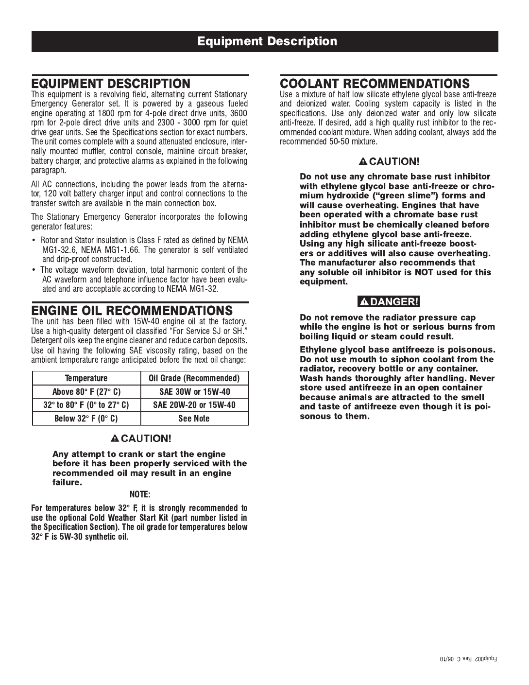
INTRODUCTION
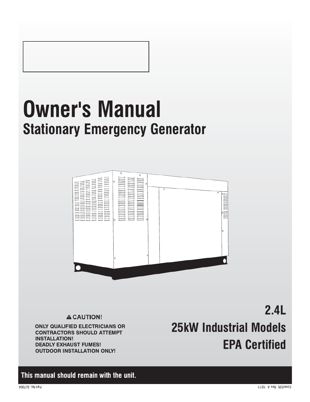
Thank you for purchasing this model of the Stationary Emergency
Generator set product line.
Every effort was expended to make sure that the information and
instructions in this manual were both accurate and current at the
time the manual was written. However, the manufacturer reserves
the right to change, alter or otherwise improve this product(s) at
any time without prior notice.
READ THIS MANUAL THOROUGHLY
If any portion of this manual is not understood, contact the near-
est Authorized Service Dealer for starting, operating and servicing
procedures.
Throughout this publication, and on tags and decals affixed to the
generator, DANGER, WARNING, CAUTION and NOTE blocks are
used to alert personnel to special instructions about a particular
service or operation that may be hazardous if performed incor-
rectly or carelessly. Observe them carefully. Their definitions are
as follows:
INDICATES A HAZARDOUS SITUATION OR
ACTION WHICH, IF NOT AVOIDED, WILL RESULT
IN DEATH OR SERIOUS INJURY.
Indicates a hazardous situation or action which,
if not avoided, could result in death or serious
injury.
Indicates a hazardous situation or action which,
if not avoided, could result in minor or moderate
injury.
NOTE:
Notes contain additional information important to a procedure
and will be found within the regular text body of this manual.
These safety warnings cannot eliminate the hazards that they
indicate. Common sense and strict compliance with the special
instructions while performing the action or service are essential to
preventing accidents.
Four commonly used safety symbols accompany the DANGER,
WARNING CAUTION and blocks. The type of information each
indicates is as follows:
n
This symbol points out important safety
information that, if not followed, could
endanger personal safety and/or property of
others.
This symbol points out potential explosion
hazard.
This symbol points out potential fire hazard.
This symbol points out potential electrical
shock hazard.
The operator is responsible for proper and safe use of the equip-
ment. The manufacturer strongly recommends that the operator
read this Owner's Manual and thoroughly understand all instruc-
tions before using this equipment. The manufacturer also strongly
recommends instructing other users to properly start and operate
the unit. This prepares them if they need to operate the equipment
in an emergency.
OPERATION AND MAINTENANCE
It is the operator's responsibility to perform all safety checks, to
make sure that all maintenance for safe operation is performed
promptly, and to have the equipment checked periodically by
an Authorized Service Dealer. Normal maintenance service and
replacement of parts are the responsibility of the owner/operator
and, as such, are not considered defects in materials or workman-
ship within the terms of the warranty. Individual operating habits
and usage contribute to the need for maintenance service.
Proper maintenance and care of the generator ensure a minimum
number of problems and keep operating expenses at a minimum.
See an Authorized Service Dealer for service aids and accessories.
Operating instructions presented in this manual assume that the
generator electric system has been installed by an Authorized
Service Dealer or other competent, qualified contractor. Installation
of this equipment is not a “do-it-yourself” project.
HOW TO OBTAIN SERVICE
When the generator requires servicing or repairs, simply contact
an Authorized Service Dealer for assistance. Service technicians
are factory-trained and are capable of handling all service needs.
When contacting a dealer about parts and service, always supply
the complete Model Number, Serial Number and Type Code (where
applicable) from the DATA LABEL that is affixed to the unit.
AUTHORIZED SERVICE DEALER LOCATION
To locate the nearest AUTHORIZED
SERVICE DEALER, please call this number:
1-800-333-1322
or locate us on the web at:
www.generac.com
Safety 001 Rev. d 06/10
Safety Rules
Study these SAFETY RULES carefully before installing, operating
or servicing this equipment. Become familiar with this Owner’s
Manual and with the unit. The generator can operate safely, effi-
ciently and reliably only if it is properly installed, operated and
maintained. Many accidents are caused by failing to follow simple
and fundamental rules or precautions.
The manufacturer cannot anticipate every possible circumstance
that might involve a hazard. The warnings in this manual, and on
tags and decals affixed to the unit are, therefore, not all inclusive.
If a procedure, work method or operating technique is used that
the manufacturer does not specifically recommend, ensure that it
is safe for others. Also make sure the procedure, work method or
operating technique utilized does not render the generator unsafe.
n
Despite the safe design of this generator,
operating this equipment imprudently,
neglecting its maintenance or being careless
can cause possible injury or death. Permit
only responsible and capable persons to
install, operate or maintain this equipment.
Potentially lethal voltages are generated by
these machines. Ensure all steps are taken to
render the machine safe before attempting to
work on the generator.
n
Parts of the generator are rotating and/or
hot during operation. Exercise care near run-
ning generators.
GENERAL HAZARDS
For safety reasons, the manufacturer recommends that this • equipment be installed, serviced and repaired by an Authorized
Service Dealer or other competent, qualified electrician or instal-
lation technician who is familiar with applicable codes, standards
and regulations. The operator also must comply with all such
codes, standards and regulations.
Installation, operation, servicing and repair of this (and related) • equipment must always comply with applicable codes, stan-
dards, laws and regulations. Adhere strictly to local, state and
national electrical and building codes. Comply with regulations
the Occupational Safety and Health Administration (OSHA) has
established. Also, ensure that the generator is installed, operat-
ed and serviced in accordance with the manufacturer’s instruc-
tions and recommendations. Following installation, do nothing
that might render the unit unsafe or in noncompliance with the
aforementioned codes, standards, laws and regulations.
The engine exhaust fumes contain carbon monoxide gas, which • can be DEADLY. This dangerous gas, if breathed in sufficient
concentrations, can cause unconsciousness or even death. For
that reason, adequate ventilation must be provided. This should
be considered prior to installing the generator. The unit should
be positioned to direct exhaust gasses safely away from any
building where people, animals, etc., will not be harmed. Any
exhaust stacks that ship loose with the unit must be installed
properly per the manufacturer's instruction, and in strict compli-
ance with applicable codes and standards.
Keep hands, feet, clothing, etc., away from drive belts, fans, • and other moving or hot parts. Never remove any drive belt or
fan guard while the unit is operating.
Adequate, unobstructed flow of cooling and ventilating air is • critical in any room or building housing the generator to prevent
buildup of explosive gases and to ensure correct generator
operation. Do not alter the installation or permit even partial
blockage of ventilation provisions, as this can seriously affect
safe operation of the generator.
Keep the area around the generator clean and uncluttered. • Remove any materials that could become hazardous.
When working on this equipment, remain alert at all times. • Never work on the equipment when physically or mentally
fatigued.
Inspect the generator regularly, and promptly repair or replace • all worn, damaged or defective parts using only factory-
approved parts.
Before performing any maintenance on the generator, discon-• nect its battery cables to prevent accidental start-up. Disconnect
the cable from the battery post indicated by a NEGATIVE, NEG
or (–) first. Reconnect that cable last.
Never use the generator or any of its parts as a step. Stepping • on the unit can stress and break parts, and may result in dan-
gerous operating conditions from leaking exhaust gases, fuel
leakage, oil leakage, etc.
ELECTRICAL HAZARDS
All Stationary Emergency Generators covered by this manual • produce dangerous electrical voltages and can cause fatal
electrical shock. Utility power delivers extremely high and dan-
gerous voltages to the transfer switch as well as the generator.
Avoid contact with bare wires, terminals, connections, etc.,
on the generator as well as the transfer switch, if applicable.
Ensure all appropriate covers, guards and barriers are in place
before operating the generator. If work must be done around
an operating unit, stand on an insulated, dry surface to reduce
shock hazard.
Do not handle any kind of electrical device while stand-• ing in water, while barefoot, or while hands or feet are wet.
DANGEROUS ELECTRICAL SHOCK MAY RESULT.
n
Save These Instructions – The manufacturer suggests that these rules for safe operation be copied
and posted in potential hazard areas. Safety should be stressed to all operators, potential operators,
and service and repair technicians for this equipment.
1-2
Safety 001 Rev. d 06/10
Safety Rules
If personnel must stand on metal or concrete while installing, • operating, servicing, adjusting or repairing this equipment,
place insulative mats over a dry wooden platform. Work on the
equipment only while standing on such insulative mats.
The National Electrical Code (NEC) requires the frame and • external electrically conductive parts of the generator to be con-
nected to an approved earth ground. This grounding will help
prevent dangerous electrical shock that might be caused by a
ground fault condition in the generator or by static electricity.
Never disconnect the ground wire.
Wire gauge sizes of electrical wiring, cables and cord sets must • be adequate to handle the maximum electrical current (ampac-
ity) to which they will be subjected.
Before installing or servicing this (and related) equipment, make • sure that all power voltage supplies are positively turned off at
their source. Failure to do so will result in hazardous and pos-
sibly fatal electrical shock.
Connecting this unit to an electrical system normally supplied • by an electric utility shall be by means of a transfer switch so as
to isolate the generator electric system from the electric utility
distribution system when the generator is operating. Failure to
isolate the two electric system power sources from each other
by such means will result in damage to the generator and may
also result in injury or death to utility power workers due to
backfeed of electrical energy.
Stationary Emergency Generators installed with an automatic • transfer switch will crank and start automatically when normal
(utility) source voltage is removed or is below an acceptable
preset level. To prevent such automatic start-up and possible
injury to personnel, disable the generator’s automatic start cir-
cuit (battery cables, etc.) before working on or around the unit.
Then, place a “Do Not Operate” tag on the generator control
panel and on the transfer switch.
In case of accident caused by electric shock, immediately • shut down the source of electrical power. If this is not pos-
sible, attempt to free the victim from the live conductor. AVOID
DIRECT CONTACT WITH THE VICTIM. Use a nonconducting
implement, such as a dry rope or board, to free the victim from
the live conductor. If the victim is unconscious, apply first aid
and get immediate medical help.
Never wear jewelry when working on this equipment. Jewelry • can conduct electricity resulting in electric shock, or may get
caught in moving components causing injury.
FIRE HAZARDS
Keep a fire extinguisher near the generator at all times. Do NOT • use any carbon tetra-chloride type extinguisher. Its fumes are
toxic, and the liquid can deteriorate wiring insulation. Keep the
extinguisher properly charged and be familiar with its use. If
there are any questions pertaining to fire extinguishers, consult
the local fire department.
EXPLOSION HAZARDS
Properly ventilate any room or building housing the generator to • prevent build-up of explosive gas.
Do not smoke around the generator. Wipe up any fuel or oil • spills immediately. Ensure that no combustible materials are left
in the generator compartment, or on or near the generator, as
FIRE or EXPLOSION may result. Keep the area surrounding the
generator clean and free from debris.
These generators may operate using one of several types • of fuels. All fuel types are potentially FLAMMABLE and/or
EXPLOSIVE and should be handled with care. Comply with all
laws regulating the storage and handling of fuels. Inspect the
unit’s fuel system frequently and correct any leaks immediately.
Fuel supply lines must be properly installed, purged and leak
tested according to applicable fuel-gas codes before placing
this equipment into service.
Diesel fuels are highly FLAMMABLE. Gaseous fluids such • as natural gas and liquid propane (LP) gas are extremely
EXPLOSIVE. Natural gas is lighter than air, and LP gas is heavier
than air; install leak detectors accordingly.
1-3
Safety 001 Rev. d 06/10
Safety Rules
CALIFORNIA PROPOSITION 65 WARNING
Engine exhaust and some of its constituents are known
to the State of California to cause cancer, birth defects
and other reproductive harm.
CALIFORNIA PROPOSITION 65 WARNING
This product contains or emits chemicals known to the
State of California to cause cancer, birth defects and
other reproductive harm.

WAUKESHA, WI
RATED KW
RATED VOLTAGE
POWER FACTOR
ENGINE RPM
ALTERNATOR SUBTRANSIENT REACTANCE
ALTERNATOR TRANSIENT REACTANCE
CLASS
MODEL
MADE IN USA
PRODUCTION DATE
GENERAC POWER SYSTEMS, INC.
HERTZ
RATED KVA
GENERATOR SET DATA
RATED AMPS
ALT RPM
PHASE
SERIAL
ROTOR STATOR WINDING INSULATION AT 25 C AMBIENT°
2-1
n
n
n
n
3-1
4-1
5-1
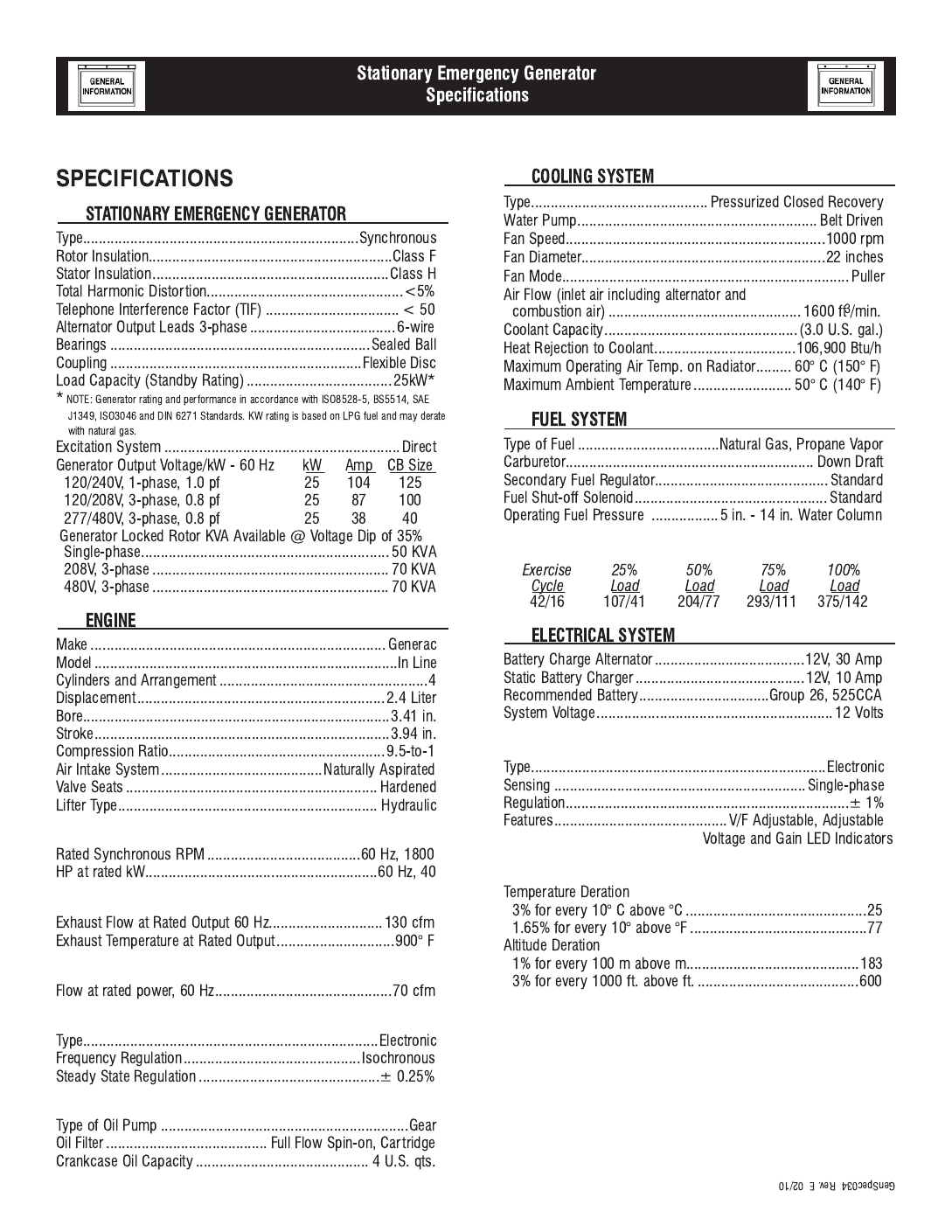
Engine Parameters
Exhaust System
Combustion Air Requirements (Natural Gas)
Governor
Engine Lubrication System
Fuel Consumption - ft3/hr (Natural Gas/LPV)
Voltage Regulator
Power Adjustment for Ambient Conditions
Controller .................................................................. H-100
6-1
6-3
E1
S10
S12
S4
S5
S2
S8
S11
S6
S3
S9
S7 S1
E2
E3
L - N
L - L
E1
S1
S4
S7
S12 S11
S10
S8
S5
S2
E2
S9
S6
S3
E3 L - N
L - L
7-1
S6
E
3
S3
INTERNAL
CO
NNE
C
TI
O
N
S
L-
N
L
-
L
S4
E2
S2
S5
S1
E1
NE
U
TRA
L
E2
E1
E
7-2
n
8-1
n
8-2
n
The Maintenance Disconnect Switch and the
AUTO/OFF/MANUAL switches (if so equipped)
must be set properly, or the generator will
crank and start as soon as the utility power to
the transfer switch is turned off. Refer to appli-
cable control panel and transfer switch manuals
for more information.
n
Do not proceed until certain that utility source
voltage is available to the transfer switch and
the transfer switch main contacts are set to
UTILITY.
Do not attempt manual operation until all
power supplies to the transfer switch have been
positively turned off, or extremely dangerous -
possibly lethal - electrical shock will result.
Transfer switch enclosure doors should be kept
closed and locked. Only authorized personnel
should be allowed access to the transfer switch
interior. Extremely high and dangerous voltages
are present in the transfer switch.
nDo not crank the engine continuously for lon-
ger than 30 seconds, or the heat may
damage the starter motor.
9-1
EVERY THREE MONTHS
ONCE EVERY SIX MONTHS
ONCE ANNUALLY
FIRST 30 OPERATING HOURS
FIRST 100 OPERATING HOURS
EVERY 500 OPERATING HOURS
n
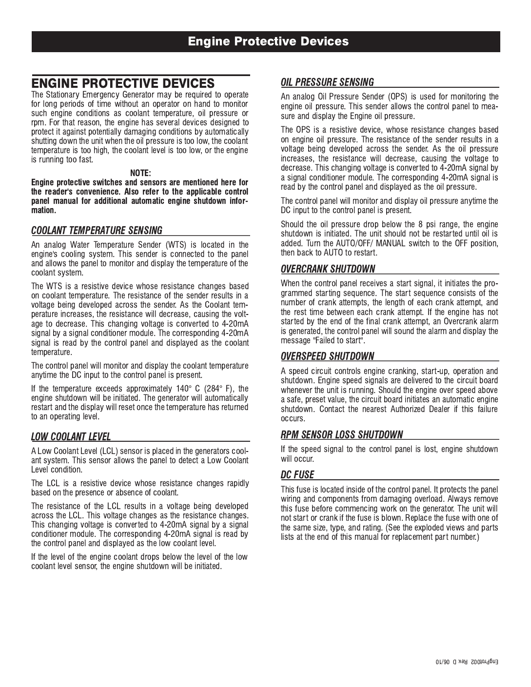
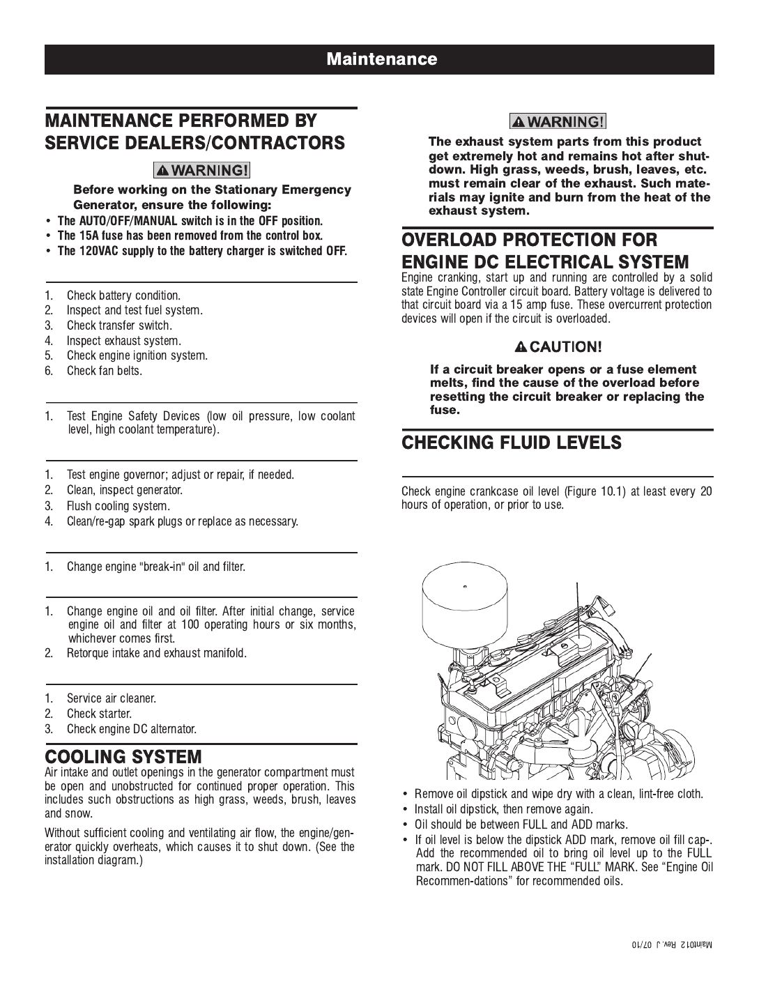
CHECK ENGINE OIL
Figure 10.1 - Oil Dipstick and Oil Fill Cap
Oil
Dipstick
Oil Fill Cap
10-1
BATTERY FLUID
ENGINE COOLANT
CHECK ENGINE OIL LEVEL
CHECK BATTERY
EXERCISE SYSTEM
INSPECT COOLING SYSTEM
CHECK ENGINE COOLANT LEVEL
PERFORM VISUAL INSPECTION
INSPECT EXHAUST SYSTEM
CHECK FAN BELT
INSPECT ENGINE GOVERNOR
n
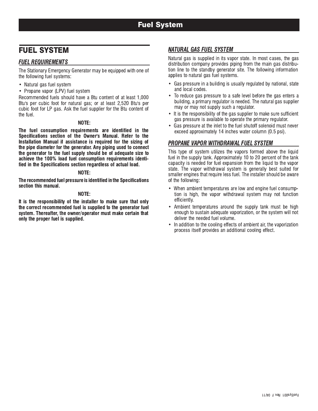
CHANGING ENGINE OIL
n
10-2
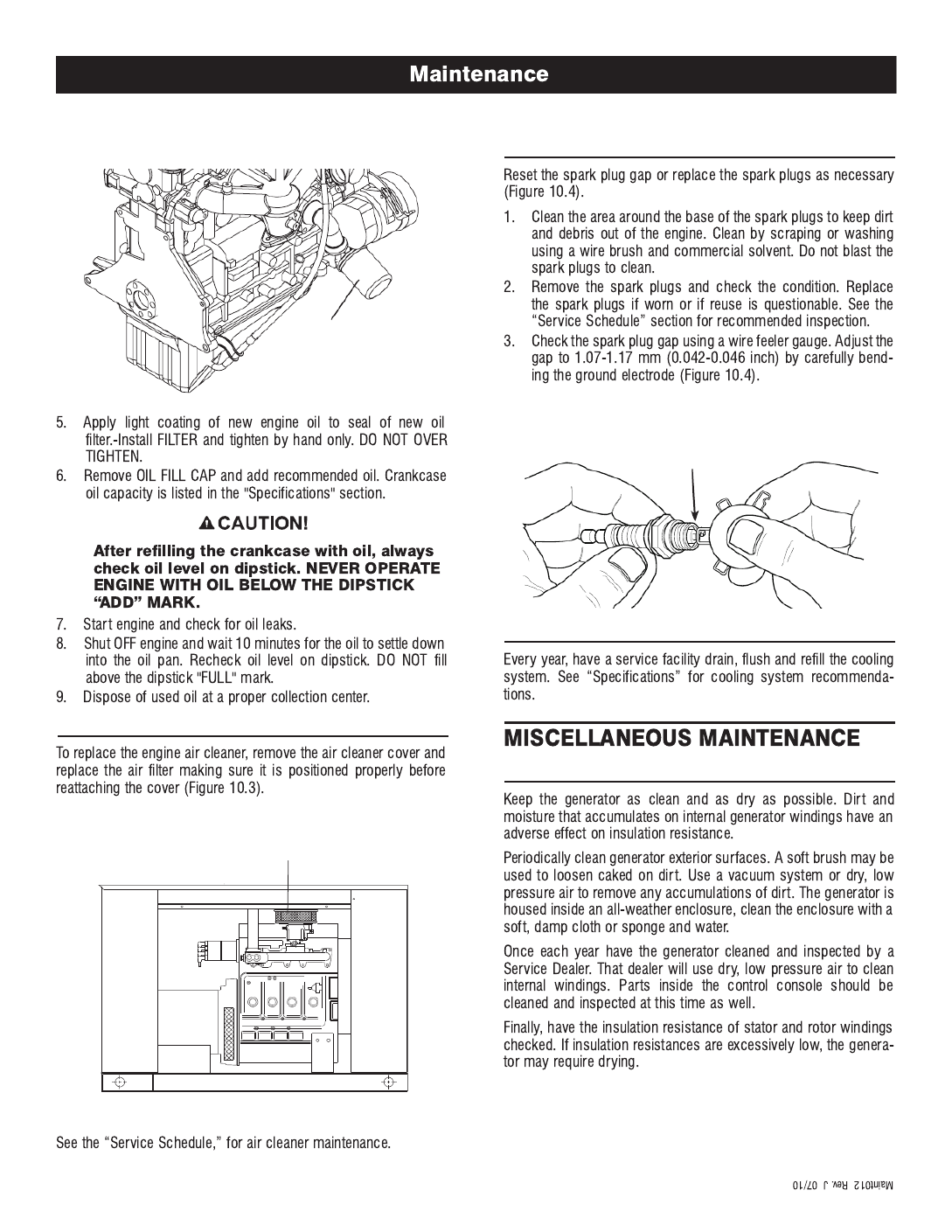
Figure 10.2 – Oil Filter
Oil
Filter
n
CHANGING THE ENGINE AIR CLEANER
Figure 10.3 – Engine Air Cleaner
Air Cleaner
(Doors Removed for Clarity)
SPARK PLUGS
Figure 10.4 – Setting the Spark Plug Gap
COOLANT CHANGE
CLEANING THE STATIONARY EMERGENCY GENERATOR
10-3
SET PLUG GAP AT 1.07 - 1.17 mm
(0.042 - 0.046 inch)
n
n
n
10-4
SERVICE SCHEDULE
22 KW - 150 KW GASEOUS STATIONARY EMERGENCY GENERATOR
The following is a recommended maintenance schedule for Gaseous Stationary Emergency Generator sets from 22kW to 150 kW in size. The
established intervals in the schedule are the maximum recommended when the unit is used in an average service application. They will need
to be decreased (performed more frequently) if the unit is used in a severe application. Use calendar time, from the previous maintenance
interval to determine the next required maintenance interval.
Service Maintenance Interval Information:
The various service maintenance intervals are designated by interval numbers as follows:
1 An early inspection of the generator set to insure it is ready to operate when required and to identify any potential problem areas.
This inspection may be performed by the end user providing the following safety steps are taken to prevent the engine from starting
automatically without warning:
To prevent injury, perform the following steps in the order indicated before starting any maintenance:
• Disable the generator set from starting and/or connecting to the load by setting the control panel Auto/Off/Manual switch to the
“OFF” position.
• Remove the 15 amp control panel fuse.
• Turn off the battery charger.*
• Remove the negative battery cable.
* The battery charger must be turned off BEFORE removing the battery cable to prevent an over current condition from burning out
sensitive control panel components and circuits.
Following all maintenance, reverse these steps to insure the unit is returned to standby setup for normal operation when required.
2 A wear-in service inspection of the generator set to insure it is ready to operate and carry the load when required, and to identify any
potential problem areas.
Performed ONLY ONCE following the first three months or the first 30 hours of operation after purchase of the unit.
This inspection contains some maintenance tasks which require special tools, equipment, and/or knowledge to accomplish and should be
performed only by a Service Dealer.
3 An operational inspection of the generator set to insure it is ready to operate and carry the load when required, and to identify any potential
problem areas.
Performed semi-annually or following each 50 hours of operation of the unit.
This inspection contains some maintenance tasks which require special tools, equipment, and/or knowledge to accomplish and should be
performed only by a Service Dealer.
4 A mid-level inspection of the generator set to insure it is ready to operate and carry the load when required, and to identify any potential
problem areas.
Performed annually or following each 100 hours of operation of the unit.
This inspection contains some maintenance tasks which require special tools, equipment, and/or knowledge to accomplish and should be
performed only by a Service Dealer.
5 A comprehensive inspection of the generator set to insure it is properly serviced and ready to operate and carry the load when required,
and to identify any potential problem areas.
Performed annually or following each 250 hours of operation of the unit.
This inspection contains some maintenance tasks which require special tools, equipment, and/or knowledge to accomplish and should be
performed only by a Service Dealer.
11-1
SrvSchd001 Rev. G 06/10
Service Schedule
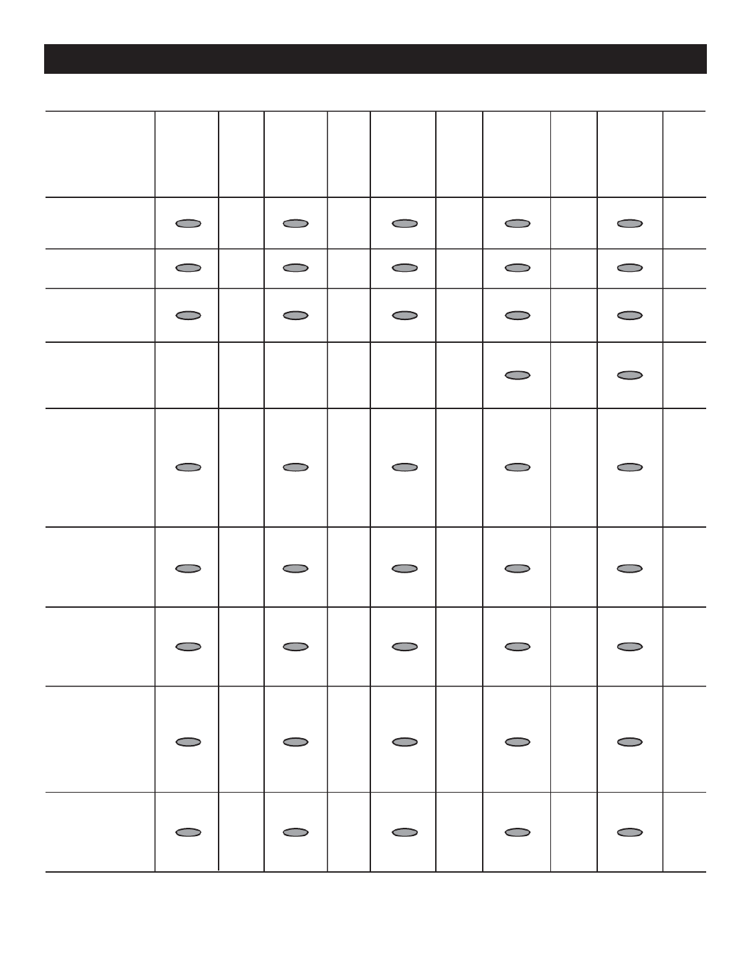
Maintenance Level 1 Level 2 Level 3 Level 4 Level 5
Tasks Recom- Task Required Task Required Task Task Required Task
mended Comp. to be done Comp. to be done Comp. Required Comp. to be done Comp.
to be done (Date- 3 months/ (Date- Semi- (Date- to be done (Date- Bi- (Date-
monthly/ Initials) Break-in Initials) annually/ Initials) Annually/ Initials) annually/ Initials)
10 hrs. 30 hrs. 50 hrs. 100 hrs. 250 hrs.
1. Disable the unit
from operating
per the first page
warning.
2. Check the engine
oil level. Adjust
as necessary.
3. Check the engine
coolant level.
Adjust as
necessary.
4. Check the engine
coolant thermal
protection level.
Correct as
necessary.
5. Check the natural
gas delivery
system for leaks
and correct
pressure on gas
engine driven
units. Tighten
connections as
necessary.
6. Check the air
inlets and outlets
of the enclosure
and radiator for
debris. Clean
as necessary.
7. Check the battery
electrolyte level
and specific
gravity if
accessible. Adjust
as necessary.
8. Check the battery
posts, cables,
and charger for
loose connections,
corrosion, and
proper operation.
Correct as
necessary.
9. Check the unit
wiring for loose
connections,
corrosion, and
damage. Correct
as necessary.
11-2
SrvSchd001 Rev. G 06/10
Service Schedule
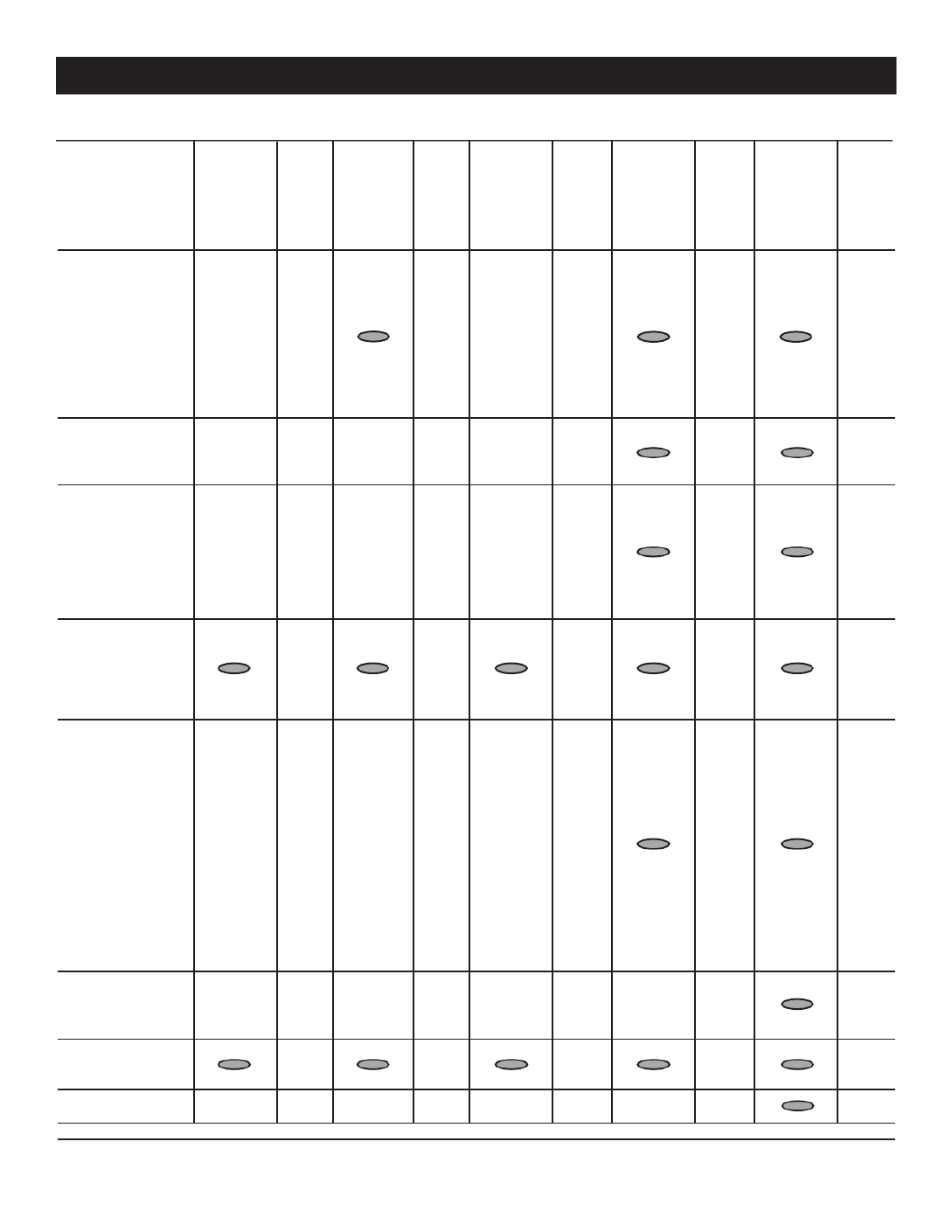
Maintenance Level 1 Level 2 Level 3 Level 4 Level5
Tasks Recom- Task Required Task Required Task Task Required Task
mended Comp. to be done Comp. to be done Comp. Required Comp. to be done Comp.
to be done (Date- 3 months/ (Date- Semi- (Date- to be done (Date- Bi- (Date-
monthly/ Initials) Break-in Initials) annually/ Initials) Annually/ Initials) annually/ Initials)
10 hrs. 30 hrs. 50 hrs. 100 hrs. 250 hrs.
10. Check the engine
accessory drive
belts and fan
coupling device
if equipped for
correct tension,
wear, weather
cracking, and
damage. Replace
as necessary.
11. Check the engine
valve clearance/
lash. Adjust as
necessary.**
12. Visually inspect
the unit looking
for leaks, wear or
damage, loose
connections or
components, and
corrosion. Correct
as necessary.
13. Test the engine
and transfer
switch safety
devices. Correct
and/or adjust as
necessary.
14. Initiate an
automatic start
and transfer of
the unit to site
load and exercise
it for at least 1
hour looking for
leaks, loose
connections or
components, and
abnormal
operating
conditions.
Correct as
necessary.
15. Replace the
engine
accessory
drive belts.
16. Check gearbox
oil level (if
equipped).
17. Change gearbox
oil (if equipped).
** Not required for engines equipped with hydraulic lifters. See the "Specification" section for lifter type.
11-3
SrvSchd001 Rev. G 06/10
Service Schedule
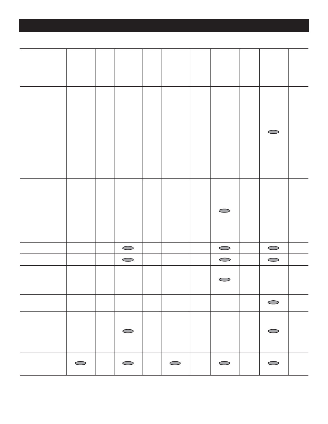
Maintenance Level 1 Level 2 Level 3 Level 4 Level5
Tasks Recom- Task Required Task Required Task Task Required Task
mended Comp. to be done Comp. to be done Comp. Required Comp. to be done Comp.
to be done (Date- 3 months/ (Date- Semi- (Date- to be done (Date- Bi- (Date-
monthly/ Initials) Break-in Initials) annually/ Initials) Annually/ Initials) annually/ Initials)
10 hrs. 30 hrs. 50 hrs. 100 hrs. 250 hrs.
18. Start and
exercise the unit
at full rated load
(use a load bank
if the site load is
not enough) for
at least 2 hours
looking for leaks,
loose
connections or
components, and
abnormal
operating
conditions.
Correct as
necessary.
19. Perform an
engine oil
analysis (send a
sample to a lab
for results).
Change the
engine oil and
filters if the
analysis results
indicate this is
required.
20. Change the
engine oil.
21. Replace the
engine oil filter(s).
22. Replace engine
spark plugs.
Clean and re-gap
or replace as
necessary.
23. Replace the
engine air
filter(s).
24. Perform a 5
minute no-load
operational run
of the unit
looking for any
post service
problems.
25. Return the unit
to standby setup
for operation
when required.
11-4
SrvSchd001 Rev. G 06/10
Service Schedule
12-1

United States Environmental Protection Agency Warranty Statement
(Stationary Emergency Spark-Ignited Generators)
Warranty Rights, Obligations and Coverage
The United States Environmental Protection Agency (EPA) and Generac Power Systems, Inc. (Generac) are pleased to explain the Emission
Control System Warranty on your new stationary emergency engine. If during the warranty period, any emission control system or compo-
nent on your engine is found defective in materials or workmanship, Generac will repair your engine at no cost to you for diagnosis, replace-
ment parts and labor provided it be done by a Generac Authorized Warranty Service Facility. Your emission control system may include parts
such as the fuel metering, ignition, and exhaust systems and other related emission related components listed below. Generac will warrant
the emissions control systems on your 2009 and later model year engines provided there has been no abuse, neglect, unapproved modifica-
tion, or improper maintenance of your engine. For engines less than 130 HP the warranty period is two years from the date of sale to the ulti-
mate purchaser. For engines greater than or equal to 130 HP the warranty period is three years or 2500 hours of operation, whichever
comes first, from the date of the engine being placed into service. For high-cost warranted components, the Emission Control System war-
ranty is valid for 5 years or 3500 hours of operation, whichever comes first.
Purchaser's/Owner's Warranty Responsibilities
As the engine purchaser/owner you are responsible for the following: 1) The engine must be installed and configured in accordance to Gen-
erac's installation specifications. 2) The completion of all maintenance requirements listed in your Owner's Manual. 3) Any engine setting
adjustment must be done in accordance and consistent with the instructions in the Owner's Manual. 4) Any emission control system or com-
ponent must be maintained and operated appropriately in order to ensure proper operation of the engine and control system to minimize
emissions at all times.
Generac may deny any/or all Emission Control System Warranty coverage or responsibility of the engine, or an emission control system or
component on your engine thereof, if it has failed due to abuse, neglect, unapproved modification or improper maintenance, or the use of
counterfeit and/or “gray market” parts not made, supplied or approved by Generac. Warranty service can be arranged by contacting either
your selling dealer or a Generac Authorized Warranty Service dealer, 1-800-333-1322 for the dealer nearest you. The purchaser/owner shall
be responsible for any expenses or other charges incurred for service calls and/or tr spection or ansportation of the product to/from the in
repair facilities. The purchaser/owner shall be responsible for any and/or all damages or losses incurred while the engine is being trans-
ported/shipped for inspection or warranty repairs. Contact Generac Power Systems Inc. for additional Emission Control System Warranty
related information, Generac Power Systems, Inc., PO. Box 8, Waukesha, WI 53187, or call 1-800-333-1322 or www.generac.com.
Important Note
This warranty statement explains your rights and obligations under the Emission Control System Warranty, which is provided to you by Gen-
erac pursuant to federal law. Note that this warranty shall not apply to any incidental, consequential, or indirect damages caused by defects
in materials or workmanship or any delay in repair or replacement of the defective part(s). This warranty is in place of all other warranties,
expressed or implied. Specifically, Generac makes no other warranties as to the merchantability or fitness for a particular purpose. Any
implied warranties which are allowed by law, shall be limited in duration to the terms of the express warranty provided herein. Some states
do not allow limitations on how long an implied warranty lasts, so the above limitation may not apply to you.
Emission Related Parts Include the Following (if so equipped)
*High-Cost Warranted Component
EmsnWrnty001 Revision F (04/15)
1) Fuel Metering System
1.1) Gasoline Carburetor Assembly and Internal Components
A) Fuel Filter, B) Carburetor, C) Fuel Pump
1.2) Carburetion Assembly and Its Components
A) Fuel Controller, B) Carburetor and Its Gaskets,
C) Mixer and Its Gaskets, D) Primary Gas Regulator,
E) Liquid Vaporizer
1.3) Fuel Regulator
2) Air Induction System Including A) Intake Pipe/Manifold,
B) Air Cleaner
3) Ignition System Including A) Spark Plug, B) Ignition Module,
C) Ignition Coil, D) Spark Plug Wires
4) Exhaust System
A) Catalyst Assembly*, B) Exhaust Manifold, C) Muffler,
D) Exhaust Pipe, E) Muffler Gasket
5) Crankcase Breather Assembly Including
A) Breather Connection Tube, B) PCV Valve
6) Oxygen Sensor
7) Diagnostic Emission-Control System

United States Environmental Protection Agency Compliance Requirements
(Stationary Emergency Spark-Ignited Generators)
Purchaser's/Owner's Record Keeping Responsibilities
The United States Environmental Protection Agency (EPA) and Generac Power Systems, Inc. (Generac) are pleased to explain your record
keeping requirements for compliance with Subpart JJJJ- Standards of Performance for Stationary Spark Ignition Internal Combustion
Engines as listed in the Electronic Code of Federal Regulations Title 40 Part 60. As the engine purchaser/owner who operates and maintains
their certified emergency stationary engine and emission control system according to applicable emission related guidelines as specified in
this Owner's Manual, you are required to meet the following notification and record keeping requirements to demonstrate compliance: 1)
Maintain documentation that the engine is certified to meet emission standards. 2) Record keeping of maintenance conducted. 3) Record
keeping of the provision allowing natural gas engines to operate using propane for a maximum of 100 hours per year as an alternate fuel
solely during emergency operations provided the engine is not certified to operate on propane. 4) Meet all compliance notifications submitted
to the purchaser/owner and maintain all supporting documentation. 5) Record keeping of hours of operation, including what classified the
operation as emergency and how many hours are spent for non-emergency operation. For emergency engines greater than or equal to 130
HP, record keeping of hours of operation begins January 1, 2011. For emergency engines less than 130 HP, record keeping of hours of oper-
ation begins January 1, 2009; engines are equipped with non-resettable hour meters to facilitate record keeping.
Specific Air Quality Management or Air Pollution Control Districts may have different and additional record keeping/reporting requirements.
Your permit to construct and/or operate the engine may be contingent upon compliance with those requirements. Check with your local Air
Quality Management or Air Pollution Control District for specific requirements.
Emergency stationary internal combustion engines (ICE) may be operated for the purpose of maintenance checks and readiness testing,
provided that the tests are recommended by Federal, State or local government, Generac, or the insurance company associated with the
engine. Maintenance checks and readiness testing of such units is limited to 100 hours per year. There is no time limit on the use of emer-
gency stationary ICE in emergency situations. The purchaser/owner may petition the Administrator for approval of additional hours to be
used for maintenance checks and readiness testing, but a petition t Federal, is not required if the owner maintains records indicating tha
State, or local standards require maintenance and testing of emergency ICE beyond 100 hours per year. Emergency stationary ICE may
operate up to 50 hours per year in non emergency situations, but those 50 hours are counted towards the 100 hours per year provided for
maintenance and testing.
The 50 hours per year for non-emergency situations cannot be used for peak shaving or to generate income for a facility to supply power to
an electric grid or otherwise supply power as part of a financial arrangement with another entity. For purchaser/owner of emergency engines,
any operation other than emergency operation, maintenance and testing, and operation in non-emergency situations for 50 hours per year,
as permitted in this section is prohibited.
If you operate and maintain your certified emergency stationary SI internal combustion engine and emissions control systems in accordance
to the specifications and guidelines in this Owner’s Manual, EPA will not require engine performance testing. If not, your engine will be con-
sidered non-certified and you must demonstrate compliance according to Subpart JJJJ - Standards of Performance for Stationary Spark Igni-
tion Internal Combustion Engines as listed in the Electronic Code of Federal Regulations Title 40 Part 60.
Emission-Related Installation Instructions
Your certified emergency stationary engine has pre-set emission control systems or components that require no adjustment. Inspection and
replacement of an emissions related component is required to be done so in accordance with the requirements cited in the United States
Environmental Protection Agency Warranty Statement or can be arranged by contacting either your selling dealer or a Generac Authorized
Warranty Service dealer, 1-800-333-1322 for the dealer nearest you. Failing to follow t ified engine in a hese instructions when installing a cert
piece of non-road equipment violates federal law 40 CFR 1068.105 (b), subject to fines or penalties as described in the Clean Air Act.
EmsnWrnty001 Revision F (04/15)


EXPLODED VIEW: EV ALTCOMPRT DIRECT B-CAN
DRAWING #: 0J5599A
GROUP A
ITEM PART# QTY. DESCRIPTION
REVISION: J-8625-D Page 2 of 4
DATE: 5/6/14
1 0G1931 1 ROTOR 25KW 3PH DIRECT 390 1800
0G2101 1 ROTOR 25KW 1PH DIRECT 390 1800
0G6568 1 RTR 390 45AD1 CPL
0G6570 1 RTR 390 45KD1 CPL
2 0G1932 1 ASSY STR 390 25 GD1 CPL
0G2098 1 ASSY STR 390 25AD1 CPL
0G2099 1 ASSY STR 390 25KD1 CPL
0G2100 1 ASSY STR 390 25JD1 CPL
0G6365 1 STR 390 45JD1 CPL
0G6569 1 STR 390 45AD1 CPL
0G6571 1 STR 390 45GD1 CPL
0G6572 1 STR 390 45KD1 CPL
0H1299 1 ASSY STR 390 36AD1 CPL
0H1300 1 ASSY STR 390 36JD1 CPL
0H1301 1 ASSY STR 390 36 GD1 CPL
0J5243 1 STR 390 48GD1 CPL
0J5427 1 STR 390 48AD1 CPL
0J6268 1 STR 390 48JD1 CPL
0J6269 1 STR 390 48KD1 CPL
3 0C9708 REF INSTR HYPOT TEST (NOT SHOWN)
4 SEE ENGINE EV REF ENGINE ADAPTER
5 SEE ENGINE EV REF FLEXPLATE
6 0F5767B 1 ASSY FLYWHEEL CPL W/40MM FAN B
7 0E5706 1 REAR BEARING CARRIER 390/DRCT
8 0F7874 1 ASSY BRUSH HOLDER 390/HSB
0F7874A 1 ASSY BRUSH HOLDER 390/HSB
(6) 0J7347 1 ASSY BRUSH HOLDER 390/HSB
(6) 0J7347A 1 ASSY BRUSH HOLDER 390/HSB
9 077043A 1 CONDUIT FLEX .38" ID (60”)
10 038150 4 WASHER FLAT #8 ZINC
11 023454 1 KEY WOODRUFF #E
12 077043F 1 CONDUIT FLEX 1.25"ID (35” LG)
13 04576100BU 4 STUD M14-2.0 570 G5 ZINC
(5) 04576100BF 4 STUD M14-2.0 X 540 G5 ZINC
14 052646 4 WASHER FLAT M14
15 043123 4 WASHER LOCK M14
16 051779 4 NUT HEX M14-2.0 G8 YEL CHR
(2) 17 0A2601 1 SCREW HHC M16-2.0 X 45 G8.8
18 072879 1 SPACER .69 X 2.75 X .37 ST/ZNC
(2) 19 059980 4 SCREW HHC M10-1.5 X 25 C10.9
20 046526 4 WASHER LOCK M10
21 0C3993 4 SCREW HHTT M4-0.7 X 25 BP
22 022264 4 WASHER LOCK #8-M4
(1) 23 047248 1 BALL BEARING-45 MM
(1) 24 070892 1 SLIP RING MACHINED
(3)25 0J7077 1 BLOCK OFF, ALTERNATOR AIR
(6)(7) 0J7348 1 BLOCK OFF, ALTERNATOR AIR QTA
(3)26 0J7077A 2 BLOCK OFF, ALT AIR LH/RH
(3)27 0J7007 1 BAFFLE-ALT INLET
(3)28 0J7086 1 PLATE LEAD CLAMP
(3)29 0C2454 19 SCREW HWHT M6-1 X 16 N WA Z/JS
(3)30 052250 1 TAPE FOAM 1X1 (166” LG)

EXPLODED VIEW: EV ALTCOMPRT DIRECT B-CAN
DRAWING #: 0J5599A
GROUP A
ITEM PART# QTY. DESCRIPTION
REVISION: J-8625-D Page 3 of 4
DATE: 5/6/14
(8)31 0J81840ST0R 1 SCROLL TOP 390 ALT CPL
(8)32 0J8184AST0R 2 SCROLL FT/RR 390 ALT CPL
(8)33 0J8184BST0R 2 SCROLL LH/RH 390 ALT CPL
34 089685 4 GROMMET .75 X .12 X .50
35 089961A 1 FOAM STRIP 3/4"WIDE X 1/4"THK (120”LG)
36 0C2266 6 SCREW PHTT M5-0.8 X 16 ZP
(7)37 056326 1 TRIM VINYL BLACK 1/8GP (10” LG)
NOTES (UNLESS OTHERWISE SPECIFIED :
(1) ROTOR REPLACEMENT PARTS.
(2) APPLY MEDIUM STRENGTH BLUE THREAD LOCKING FLUID TO THREADS.
(3) NOT USED IN OPEN SETS.
(4) TORQUE VALUES: (FOR REFERENCE ONLY)
ITEM #16 - 45 ft-lbs.
ITEM #17 - 144 ft-lbs.
ITEM #19 - 56 ft-lbs.
(5) 5.4L ONLY
(6) QTA ONLY
(7) 60KW ONLY
(8) SHEET METAL PARTS LISTED IN THE BOM TABLE ARE REPRESENTING GENERIC PARTS (NO COLOR)
• MANUFACTURING: FOR CORRECT MATERIAL AND COLOR REFER TO AS400 BOM.
• CUSTOMER: WHEN ORDERING REPLACEMENT PARTS ENTER BASE NUMBER (FIRST 6 DIGITS ONLY) IN THE SYSTEM FOR CORRECT MATERIAL
AND COLOR (FOR REFERENCE SEE GUIDELINE 0H7169).
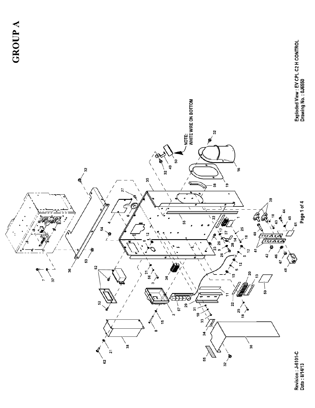

EXPLODED VIEW: EV CPL C2 H CONTROL
DRAWING #: 0J6550
GROUP A
ITEM PART# QTY. DESCRIPTION
REVISION: J-6101-C Page 3 of 4
DATE: 8/14/13
1 0H0026 1 DECAL CHARGER POWER 120VAC C2
2 0G4649 1 ASSY PCB 2.4L IGN MOD PRGMMED
3 0C2266 2 SCREW PHTT M5-0.8 X 16 ZP
4 0F6156 1 PLATE WIRE SNGL GALV
5 022152 7 WASHER LOCK #10
6 081008B 1 GROMMET 1.25 X .25 X 1.00
7 0E3257 4 SCREW HWHTF M6-1.0 X 16
8 036943 2 SCREW PPHM #10-32 X 2
9 022097 1 WASHER LOCK M6-1/4
10 022264 6 WASHER LOCK #8-M4
11 0J0398 1 DECAL, CONTACT RAT 30VAC/30VDC
12 022158 7 NUT HEX #10-32 STEEL
13 0F3618A 1 DECAL CPL CUST CONN H CONTROL
14 067210A 1 DECAL GROUND LUG
15 023897 5 WASHER FLAT #10 ZINC
16 0H6160 1 COVER WIRE ENTRY CONNBOX
(1)17 0D4698 REF BLOCK TERM 20A 6 X 3 X 1100V
18 0C2428 4 SCREW PHTT #6-32 X 1/2 ZYC
19 0J3060 1 GASKET WIRE ENTRY COVER
20 057701 REF BLOCK TERM 20A 8 X 6 X 1100V
21 051713 6 WASHER FLAT M5
22 0J0575 2 DECAL, CUSTOMER WIRE #14
23 022473 4 WASHER FLAT 1/4-M6 ZINC
24 0J6810 1 DECAL CONBOX TB2 CONNECTIONS
25 022155 4 WASHER LOCK #6
26 0D6029 5 SCREW HHTT M6-1.0 X 16 ZYC
27 0F5458 2 SCREW HHSP #10 X 3/8 HI-LOW
28 055414 1 LUG SLDLSS #2-#8 X 17/64 CU
29 0E9764 1 RAIL SNAPTRACK PCB HOLDER BULK (6”LG)
(3)30 0J65610ST0R 1 SHIELD HIGH/LOW C2 CPL H
31 043180 3 WASHER FLAT M4
(4)32 0C2454 12 / 13 SCREW HWHT M6-1 X 16 N WA Z/JS
33 0C3990 3 SCREW PHTT M4-0.7 X 10 ZP
(1)34 0D7393U REF TERM BLOCK 4P UL 12-20AWG
35 0J6564 1 BK PNL CONBOX SUPPORT C2 QTA
36 0J6565 1 BACK PNL CONBOX TOP C2
37 026850 5 WASHER LOCK EXT 1/4 STL
38 0J0157 1 INTERFACE 1PH 120/240V
0J0156 1 INTERFACE 3PH 208/240V
0J0155 1 INTERFACE 3PH 416/480V
39 057073 2 JUNCTION BLOCK 3/8-16
40 039287 1 SCREW HHC M8-1.25 X 45 C8.8
(2)41 0D5466 REF BUSBAR NEUTRAL BLOCK 390
42 067989 1 NUT HEX FL WHIZ M8-1.25
43 0C2265 4 SCREW PHTT M4-0.7 X 12 ZP
(2)44 045335 REF SCREW HHC 1/4-28 X 3/4 G5
(2)45 083896 REF WASHER LOCK 1/4-M6 SS
46 022237 2 WASHER LOCK 3/8
47 022241 2 NUT HEX 3/8-16 STEEL
(2)48 0A7822 REF LUG SLDLSS 600/250-1/0X1/4-28
(4)49 0J1857 2 / 3 CT BRKT 1.1" WINDOW FRAME
50 0J0481 3 XFMR CURRENT 50A W/BRKT UL RCG
0J0481A 3 XFMR CURRENT 100A W/O BRKT U
0J0481B 3 XFMR CURRENT 150A W/O BRKT UL
0J0481C 2 XFMR CURRENT 200A W/O BRKT UL
51 0J7175 1 HARN CONBOX G2.4L G2 QTA (NOT SHOWN)
52 0F6207 1 OUTLET 20A GFCI 125V
53 0D3700 4 NUT FLANGE M6-1.0 NYLOK
54 082625 2 NUT LOCK HEX #6-32 NYL INSERT
55 029289 1 TAPE ELEC 1/2 FOAM (61” LG)
56 049226 2 WASHER LOCK M5
57 0G6962B 1 ASSY RELAY PCB 12VDC
(5)58 056326 1 TRIM VINYL BLACK 1/8GP (13” LG)
59 0H8006 1 DECAL CAUTION ELEC SHOCK SM
60 0F6146 1 HANG TAG 2 WIRE START (NOT SHOWN)

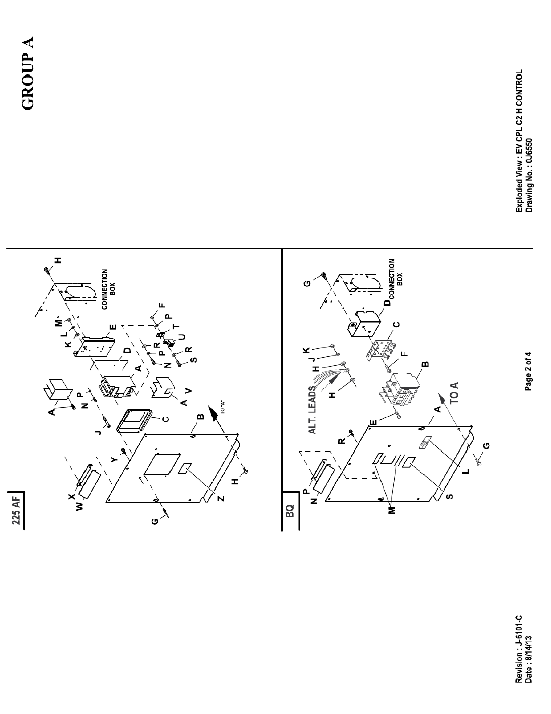
EXPLODED VIEW: EV CPL C2 H CONTROL
DRAWING #: 0J6550
GROUP A
ITEM PART# QTY. DESCRIPTION
REVISION: J-6101-C Page 4 of 4
DATE: 8/14/13
61 0A9457 1 DECAL NEUTRAL
62 036701 4 SCREW PPHM #10-32 X 1/2
UL CIRCUIT BREAKER (225AF)
A 0G5250 1 CB 175A 2 POLE 240V 225AF
B 0J6586 1 COVER CB G 225AF C2-C4
C 0F4186AGS0R 1 COVER CB DISH 2P G 225AF
D 0F8432A 1 INSULATOR CB 2P 225AF
E 0H7311 1 STANDOFF CB BOX CONBOX
F 045771 2 NUT HEX M8-1.25 G8 CLEAR ZINC
G 036261 4 RIVET POP .125 X .275 SS
H 0C2454 11 SCREW HWHT M6-1 X 16 N WA Z/JS
J 053640 2 SCREW RHM #8-32 X 3-1/4
K 038150 2 WASHER FLAT #8 ZINC
L 022264 2 WASHER LOCK #8-M4
M 022471 2 NUT HEX #8-32 STEEL
N 049897 4 SCREW SHC M8-1.25 X 20 G8
P 022129 6 WASHER LOCK M8-5/16
R 022145 4 WASHER FLAT 5/16-M8 ZINC
S 058306 2 SCREW SHC M8-1.25 X 25 C12.9
T 0F8843 2 BUS BAR 200A LUG ADAPTOR
U 0F8451 2 LUG SLDLSS 300 MCM-6 AL/CU
V 0G3259 1 DECAL TERMINAL SHOCK HZD BI
(3)W 0J78740ST0R 1 SHIELD-SM CIRCUIT BREAKER
X 0J7872 1 GASKET-CB SHIELD C2
Y 0E3257 2 SCREW HWHTF M6-1.0 X 16
Z 0K4772 1 DECAL SERVICE DISCONNECT
UL CIRCUIT BREAKER (BQ)
A 0J6585 1 COVER BQ3 CB C2 CPL
0J6584 - COVER BQ2 CB C2 CPL
B 0A2077 1 CB 0125A 2P 240V S BQ2 LL
040532 - CB 0100A 3P 240V S BQ3 LL
062812 - CB 0080A 3P 240V S BQ3 LL
C 0E7890 1 BRKT CB MTG BACK
0E6002 - MTG TRACK BQ SIEMENS CB 3P
D 0J6583 1 BRKT BQ CB STANDOFF
(4)E 022859 2/3 SCREW RHM #10-32 X ¾
F 0C3990 2 SCREW PHTT M4-0.7 X 10 ZYC
G 0C2454 11 SCREW THF M6-1 X 16 N WA Z/JS
(4)H 023897 4/6 WASHER FLAT #10 ZINC
(4)J 022152 2/3 WASHER LOCK #10
(4)K 022158 2/3 NUT HEX #10-32 STEEL
L 0F1733 1 DECAL CUSTOMER CONNECT INSIDE
M 029289 2 TAPE ELEC 1/2 FOAM
(3)N 0J78740ST0R 1 SHIELD-SM CIRCUIT BREAKER
P 0J7872 1 GASKET-CB SHIELD C2
R 0E3257 2 SCREW HWHTF M6-1.0 X 16
S 0K4772 1 DECAL SERVICE DISCONNECT
(1) ITEMS INCLUDED WITH HARNESS P/N 0J7175.
(2) ITEMS INCLUDED WITH NEUTRAL BLOCK P/N 0D5464B.
(3) SHEET METAL PARTS LISTED IN THE BOM TABLE ARE REPRESENTING GENERIC PARTS (NO COLOR)
• MANUFACTURING: FOR CORRECT MATERIAL AND COLOR REFER TO AS400 BOM.
• CUSTOMER: WHEN ORDERING REPLACEMENT PARTS ENTER BASE NUMBER (FIRST 6 DIGITS ONLY) IN
THE SYSTEM FOR CORRECT MATERIAL AND COLOR (FOR REFERENCE SEE GUIDELINE 0H7169
(4) QTY. REQ. FOR 2 POLE BREAKER / QTY. REQ. FOR 3 POLE BREAKER.
(5) OPEN SET ONLY.
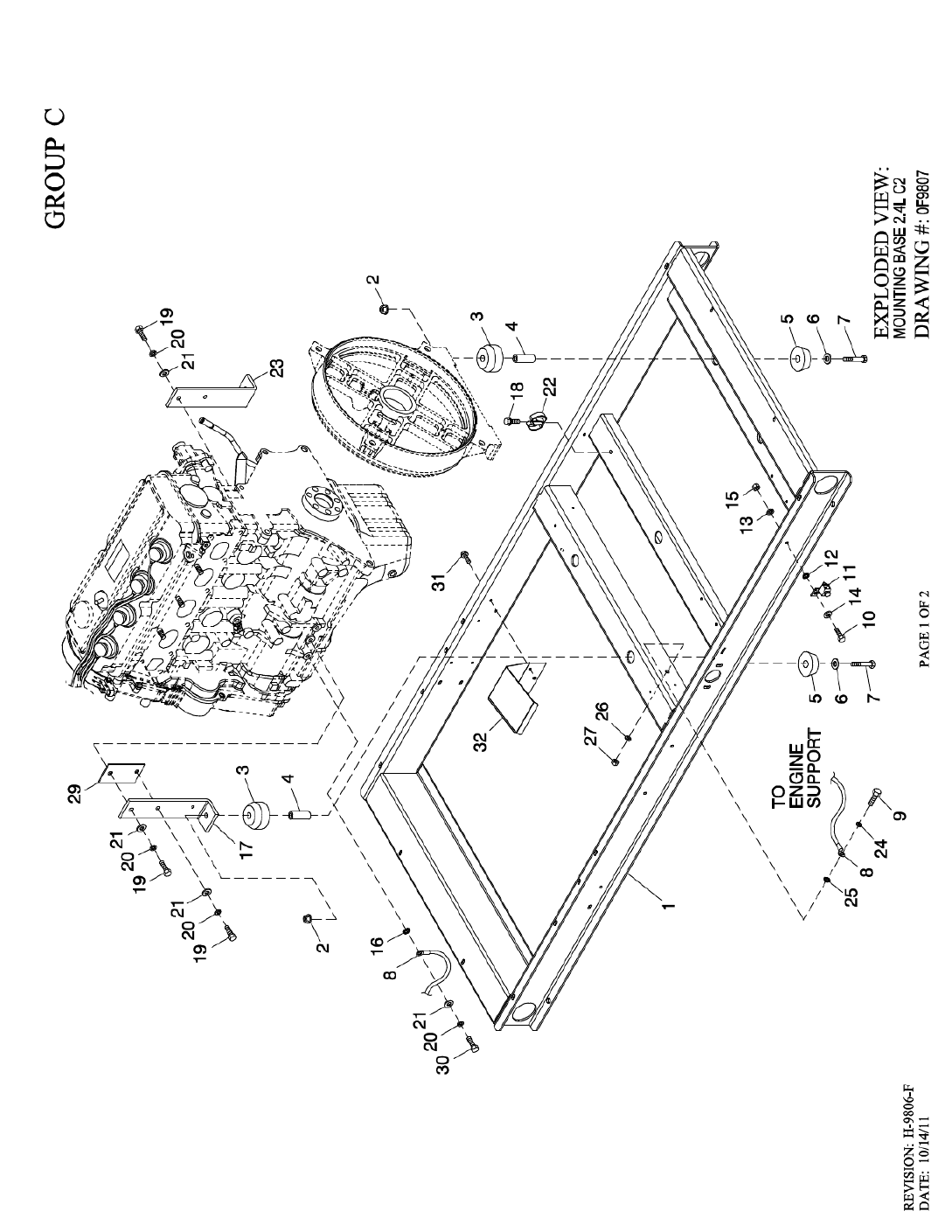
1 0F9517 1 WELDMENT FRAME 2.4L C2
2 052860 4 NUT FLANGED HEX M12-1.75
3 052251 4 DAMPENER VIBRATION 40 BLUE
4 052257 4 SPACER .49 X .62 X 1.87 PWDR/ZNC
5 052252 4 DAMPENER VIBRATION
6 052259 4 WASHER FLAT M12
7 052891 4 SCREW HHC M12-1.75 X 80 G8.8
8 0536210410 1 ASSY WIRE 14.00"
9 042909 1 SCREW HHC M8-1.25 X 30 G8.8
10 047411 1 SCREW HHC M6-1.0 X 16 G8.8
11 055414 1 LUG SLDLSS #2-#8 X 17/64 CU
12 0A1658 1 WASHER LOCK SPECIAL 1/4"
13 022097 1 WASHER LOCK M6-1/4
14 022473 2 WASHER FLAT M6-1/4 ZINC
15 049813 1 NUT HEX M6 -1.0 G8 YEL CHR
16 022261 1 WASHER SHAKEPROOF INT 3/8
17 0F9597A 1 SUPPORT LH ENGINE 2.4L
18 045764 1 SCREW HHTT M4-0.7 X 8 BP
19 062963 4 SCREW HHC M10-1.25 X 30 G8.8
20 022302 5 WASHER LOCK 7/16
21 022131 5 WASHER FLAT 3/8-M10 ZINC
22 065852 1 SPRING CLIP HOLDER .37-.62
23 0F9597 1 SUPPORT RH ENGINE 2.4L
24 022129 1 WASHER LOCK M8-5/16
25 0C3168 1 WASHER LOCK SPECIAL 5/16
26 022145 1 WASHER FLAT 5/16-M8 ZINC
27 045771 1 NUT HEX M8-1.25 G8 CLEAR ZINC
29 0F9596 1 SPACER ENGINE MOUNT (2.4L G1)
0F9596A 1 SPACER LH ENGINE MOUNT (2.4L G2)
30 052212 1 SCREW HHC M10-1.25 X 25 C8.8
31 0C2454 3 SCREW HWHT M6-1 X 16 N WA Z/JS
32 0H5718 1 HEAT SHIELD 2.4L G2
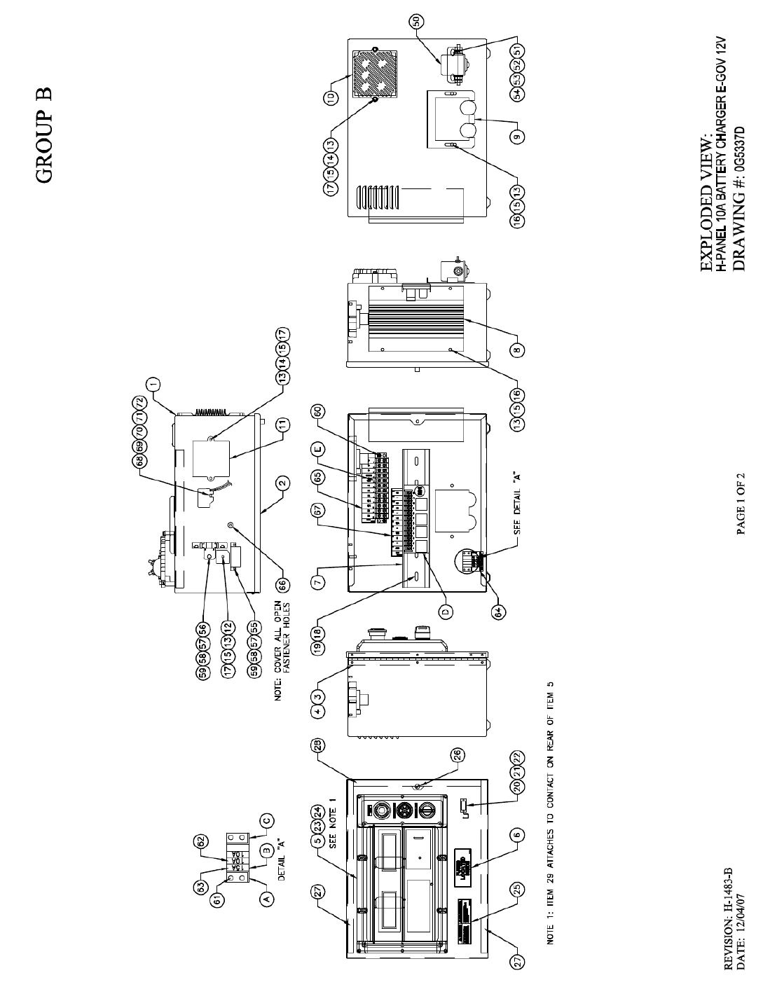
1 0F3408B 1 BATTERY TRAY C1 CPL
2 0F3411 1 STRAP BATTERY RETAINMENT
3 025507 REF WASHER SHAKEPROOF EXT 7/16 STL
4 052212 REF SCREW HHC M10-1.25 X 25 G8.8
5 046526 REF WASHER LOCK M10
6 022131 REF WASHER FLAT 3/8-M10 ZINC
7 050331A REF BATTERY POST COVER RED +
8 050331 REF BATTERY POST COVER BLACK -
9 038805Y 1 CABLE BATTERY BLACK #1 X 18.00
10 03880400AE 1 CABLE BATT RED #1 X 18.00
11 045771 REF NUT HEX M8-1.25 G8 YEL CHR
12 022129 REF WASHER LOCK M8-5/16
14 0F3976 1 BOOT CONTACTOR CABLES
15 0C2454 4 SCREW THF M6-1 X 16 N WA Z/JS
16 022145 REF WASHER FLAT 5/16-M8 ZINC
17 077483 REF BATTERY 12VDC 75-AH 26
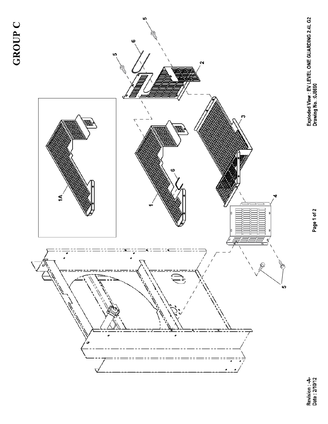

EXPLODED VIEW: EV LEVEL ONE GUARDING 2.4L G2
DRAWING #: 0J8690
GROUP C
APPLICABLE TO:
REVISION: -A-
DATE: 2/10/12
ITEM PART# QTY. DESCRIPTION
1 0J8687 1 GUARD LEVEL 1 G2 TOP
1A (1) 0J8687A 1 GUARD LEVEL 1 G2 TOP
2 0J8688 1 GUARD LEVEL 1 G2 RH
3 0J8689 1 GUARD LEVEL 1 G2 BOTTOM
4 0J8691 1 GUARD LEVEL 1 G2 LH
5 0C2454 17 SCREW THF M6-1X16 N WA Z/JS
6 056326 1 TRIM VINYL BLACK 1/8GP (18”LG)
(1) USED WITH INTAKE MANIFOLD 0G8488 0NLY.
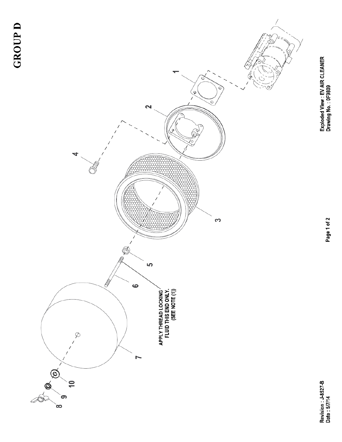

EXPLODED VIEW: EV AIR CLEANER
DRAWING #: 0F9809
GROUP D
ITEM PART# QTY. DESCRIPTION
REVISION: J-8527-B Page 2 of 2
DATE: 5/7/14
1 0E6586 1 GASKET BOSCH 32 & 40
2 0E0519A 1 ADAPTER CARBURETOR W/PVC CONN
3 0C8127 1 ELEMENT AIR CLEANER
4 049815 4 SCREW HHC M5-0.8 X 16 G8.8
5 022127 1 NUT HEX 1/4-20 STEEL
(1) 6 062974 1 STUD TH 1/4-20 X 4-1/2 G2 ZNC
7 0G0190 1 PLATE, AIR CLEANER TOP 2.4L
8 025870 1 NUT WING 1/4-20
9 022097 1 WASHER LOCK M6-1/4
10 022473 1 WASHER FLAT 1/4-M6 ZINC
(1) APPLY MEDIUM STRENGTH BLUE THREAD LOCKING FLUID TO THREADS.
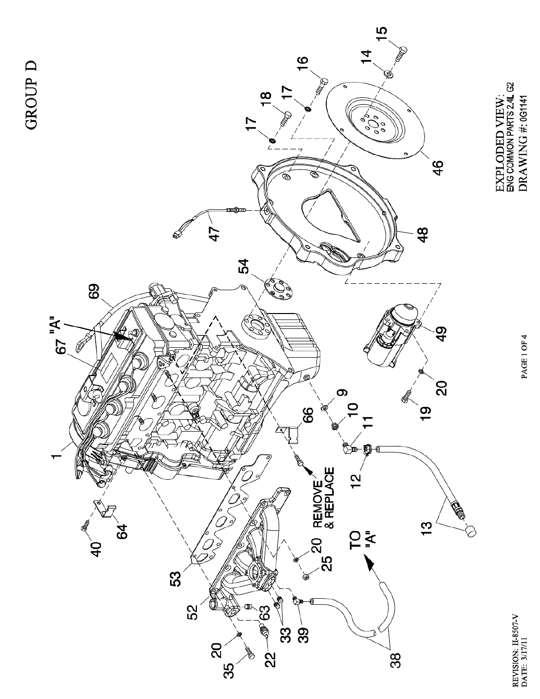
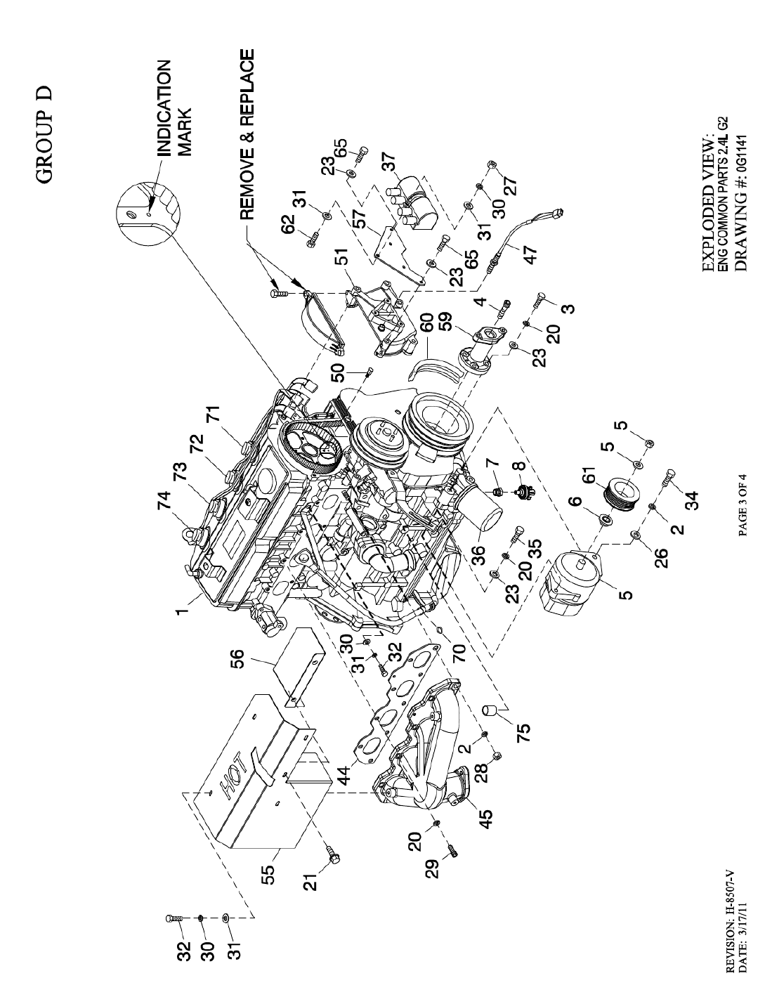
1
0H1951
1
ENGINE 2.4L G2 4G64 CERT
0H1619 1 ENGINE 2.4L G2 CERTIFIED
2 046526 3 WASHER LOCK M10
3 039414 4 SCREW HHC M8-1.25 X 35 G8.8
4 0G0149 1 SCREW SHC M14-1.5 X 35 G10.9
5 0E9868A 1 ALTERNATOR DC W/OUT PULLEY
6 0F3217 1 SPACER DC ALTERNATOR PULLEY
7 042574 1 ADAPTOR 1/8 NPTF TO 1/8 BSPT
8 0A8584 1 SWITCH OIL PRESSURE 10 PSI 2 POL (R-PANEL)
0F4612 1 SENDER OIL PRESSURE 1/8" NPT (H-PANEL)
9 057772 1 WASHER NYLON .565
10 057765 1 ADAPTER M14-1.50 X 3/8 NPT
11 043790 1 BARBED EL 90 3/8 NPT X 3/8
12 0C7649 1 CLAMP HOSE .38-.87
13 069860E 1 HOSE DRAIN ASSY 28"
14 063076 7 WASHER FLAT .531 ID X 1.062 OD
15 0G1394 7 SCREW HHC M12-1.25 X 20 G10.9
16 052830 2 SCREW HHC M10-1.25 X 45 G8.8
17 025507 5 WASHER SHAKEPROOF EXT 7/16 STL
18 062963 3 SCREW HHC M10-1.25 X 30 G8.8
19 049821 3 SCREW SHC M8-1.25 X 30 G12.9
20 022129 26 WASHER LOCK M8-5/16
21
0D6029
3
SCREW THF M6
-
1 X 16 N WA Z/JS
22 0A6751 1 SWITCH HI-TEMP 245D X 3/8 NPT (R-PANEL)
0E0502 1 TEMPERATURE SENDER DELPHI (H-PANEL)
23 022145 7 WASHER FLAT 5/16-M8 ZINC
25 045771 3 NUT HEX M8-1.25 G8 CLEAR ZINC
26 022131 1 WASHER FLAT 3/8-M10 ZINC
27 049813 3 NUT HEX M6 X 1.0 G8 YEL CHR
28 046525 2 NUT HEX M10-1.25 G8 YEL CHR
29 058306 7 SCREW SHC M8-1.25 X 25 G12.9
30 022097 7 WASHER LOCK M6-1/4
31 022473 10 WASHER FLAT 1/4-M6 ZINC
32 043116 4 SCREW HHC M6-1.0 X 12 G8.8
33 026073A 2 PLUG STD PIPE 1/4 STEEL SQ HD
34 052243 1 SCREW HHC M10-1.5 X 60 G8.8
35 0A8258 9 SCREW HHC M8-1.25 X 25 G10.9
(1) 36 0G0664 1(REF) OIL FILTER G2 ENGINE
37 0G1502 1 COIL PACK
38 047290 1 HOSE 3/8 ID SINGLE BRAID (15” LG)
39 049340 1 BARBED EL 90 1/4 NPT X 3/8
(3) 40 045757 1 SCREW HHC M6-1.0 X 25 G8.8
(1) 44 0G0951 1(REF) GASKET EXHAUST MANIFOLD
45 0G3910 1 EXHAUST MANIFOLD G2 (MACHINE) (25KW, 35KW & 45KW)
46 0F9965E 1 FLEX PLATE 2 POLE 2.4L G2
47 0D2244M 2 ASSY MAGPICKUP(3/8-24 MALE)
48 0F9420 1 ADAPTER ENGINE 2.4L MACHINE
49 0G7461 1 STARTER MOTOR 12V
50 0G1472A 1 CAM SENSOR PIN ASSY
51 0G1476 1(REF) COVER CAM GEAR G2 REWORKED
52 0G0707 1 MANIFOLD INTAKE (USE HOSE 0G0816)
0G8488 1 MANIFOLD INTAKE (MACHINED) (USE HOSE 0H1546)
(1) 53 0G0950 1(REF) GASKET INTAKE MANIFOLD
54 0F9583 1 SPACER 2.4L G2 FLEX PLATE
55 0G0792 1 SHIELD HEAT G2
56 0G0792A 1 SHIELD HEAT SML
57 0G1501 1 BRACKET COIL PACK
59 0F9501 1 ADAPTER 2.4L CRANKSHAFT MACH
(1) 60 0G0952 1(REF) POLY V-BELT G2 (3600 RPM)
0D3488S 1 BELT SERPENTINE 37.0" (1800 RPM)
61 0G0788 1 PULLEY DC ALTERNATOR (3600 RPM)
0H8572 1 PULLEY DC ALTERNATOR (1800 RPM)
62 049721 3 SCREW HHC M6-1.0 X 35 G8.8 BLK
63 026925 1 PLUG STD PIPE 3/8 STEEL SQ HD
(3) 64 0F2776 1 BRACKET, SIGNAL CONDITIONER
65 052203 2 SCREW HHC M8-1.25 X 70 G8.8
(3) 66 0F2776D 1 BRACKET SIGNAL CONDITONER
67 0G9378 1(REF) DECAL SORE EPA CERTIFICATION
69 0G10080125 1 ROD ASSY OIL LEVEL GAUGE
70 0G3823 1 O-RING SIZE 9.0MM X 2.0MM NITR
71 0G10080288 1 CABLE, SPARK PLUG, NO.1
72 0G10080289 1 CABLE, SPARK PLUG, NO.2
73 0G10080290 1 CABLE, SPARK PLUG, NO.3
74 0G10080291 1 CABLE, SPARK PLUG, NO.4
(2) 75 0G9520 1(REF) PLUG TAPER
(1) SUPPLIED WITH ENGINE.
(2) APPLY LOCTITE 620 BEARING RETAINMENT
COMPOUND TO I/N 75.
(3) USED WITH H-PANEL ONLY


EXPLODED VIEW: EV COOLING SYSTEM & FAN DRIVE
DRAWING #: 0H3075
GROUP D
ITEM PART# QTY. DESCRIPTION
REVISION: K-1082-D Page 2 of 4
DATE: 11/12/14
1 0H30830ST03 1 WELDMENT RADIATOR SUPPORT C2
2 0F2608 1 RADIATOR 598 X 568 X 49 CPL RH
3 0F5263 1 V-BELT 31/64" X 57-3/8"
4 046526 5 WASHER LOCK M10
(1) 5 059981 4 SCREW HHC M10-1.5 X 30 G10.9
6 0F2776A 1 BRACKET, SIGNAL CONDITIONER (USED
ONLY WITH QTA PRODUCT)
7 0F5050A 1 SHIELD RADIATOR C4
8 029032 2 HOSE 9/32 ID (27”LG)
9 0F2573 1 PULLEY FAN V-GROOVE 9"
10 0F4011 1 FAN COOL 22" DIA 10 BLADE LH
11 0H20620ST03 1 ARM BELT TENSIONER
(1) 12 0H2051 1 SHOULDER BOLT 1/2 X 2-1/4"
13 0F2862 1 SPRING TENSION CPL
14 0F2560 1 PULLEY V-BELT 4" FLANGED
15 022131 4 WASHER FLAT 3/8-M10 ZINC
16 0E2507 1 PROBE, COOLANT LEVEL 3/8NPTF
0H1827 1 PROBE COOLANT LEVEL 3/8-18NPTF
17 035685 2 CLAMP HOSE #28 1.32-2.25
18 0F2561 1 HUB FLEX PLATE
19 0C8145 8 WASHER FLEX (THIN)
20 052250 2 TAPE FOAM 1 X 1 (26.75” LG)
21 0C7043 12 DISK FLEX
22 0C8165 2 NUT HEX LOCK 5/16-24 NY INS
23 022473 8 WASHER FLAT 1/4-M6 ZINC
(1) 24 0C8146 4 SCREW HHC 5/16-24 X 1.124
25 022097 16 WASHER LOCK M6-1/4
26 076749 1 TANK COOLANT RECOVERY
(2) 27 048031C 2(REF) CLAMP HOSE BAND 1/4
28 031971 1 BEARING #6205 2NSE C3 E SRI2 S
29 0F4496 1 PULLEY 4.5" DIA MACHINED
(1) 30 042911 1 SCREW HHC M10-1.5 X 30 G8.8
31 0F2872 1 SCREW HHC 1/2-13 X 2" G8
32 022304 1 WASHER FLAT 1/2 ZINC
33 022195 1 WASHER LOCK 1/2
34 022196 1 NUT HEX 1/2-13 STEEL
35 0F8651 9 SCREW HHFC M8-1.25 X 20 W/M6
36 099502 2 CLAMP HOSE #24 B1.06-2.00
37 0F9867 1 SHAFT FAN DRIVE
38 0F2461 1 RETAINER BEARING
39 022145 14 WASHER FLAT 5/16-M8 ZINC
40 022129 10 WASHER LOCK M8-5/16
(1) 41 039287 1 SCREW HHC M8-1.25 X 45 C8.8
42 082774 1 KEY WOODRUFF 4 X 19D
43 0G0795 1 HOSE LOWER RADIATOR G2
44 0G0816 1 HOSE UPPER RADIATOR G2 (USED WITH MANFLD P/N 0G0707)
0H1546 1 HOSE UPPER RADIATOR G2 (USED WITH MANFLD P/N 0G8488)
45 049813 8 NUT HEX M6 X 1.0 G8 YEL CHR
46 052644 1 SPACER .5 X 1.5 X .25 STL/ZINC
47 0C8566 16 SCREW HHFC M6-1.0 X 20 G8.8
48 0C2454 2 SCREW THF M6-1 X 16 N WA Z/JS
49 090283 1 CAP RADIATOR 13 PSI
50 0L01050ST0R 1 BRACKET COOLANT TANK
51 052677 1 WASHER NYLON .50 X .87 X .06
52 0H30880ST03 1 BRACKET TENSIONER SPRING
53 039253 2 SCREW HHC M8-1.25 X 20 C8.8
(3) 54 0H2844 2 (REF) BEARING SLEEVE 1/2/ X 3/4 X 1
55 049820 2 NUT HEX LOCK M8-1.25 NY INS
56 0G53150AL0R 1 SPACER CPL COOLING FAN 1/8"
(4) 57 0H1851 1 ASSY PCB LCL SENSOR (USE WITH I/N 16, P/N 0H1827 ONLY)
(4) 58 029333A 9 TIE WRAP UL 7.4” X .19” BLK (NOT SHOWN)
59 0D3700 8 NUT FLANGE M6-1.0 NYLOK

EXPLODED VIEW: EV COOLING SYSTEM & FAN DRIVE
DRAWING #: 0H3075
GROUP D
ITEM PART# QTY. DESCRIPTION
REVISION: K-1082-D Page 4 of 4
DATE: 11/12/14
This page left blank intentionally
Specyfikacje produktu
| Marka: | Generac |
| Kategoria: | generator |
| Model: | QT02524KVANA |
Potrzebujesz pomocy?
Jeśli potrzebujesz pomocy z Generac QT02524KVANA, zadaj pytanie poniżej, a inni użytkownicy Ci odpowiedzą
Instrukcje generator Generac

10 Lutego 2025
8 Stycznia 2025
14 Października 2024
8 Października 2024
8 Października 2024
8 Października 2024
8 Października 2024
8 Października 2024
8 Października 2024
8 Października 2024
Instrukcje generator
- generator Yamaha
- generator Joy-It
- generator Braun
- generator Honda
- generator Voltcraft
- generator Philips
- generator Endress
- generator Simpson
- generator Dometic
- generator Bosch
- generator Parkside
- generator GW Instek
- generator Global
- generator Toolcraft
- generator Stanley
- generator Black & Decker
- generator Scheppach
- generator Bluetti
- generator Subaru
- generator Ribimex
- generator Westinghouse
- generator Domo
- generator Taurus
- generator DeWalt
- generator Einhell
- generator Hyundai
- generator Rowenta
- generator Husqvarna
- generator Honeywell
- generator Makita
- generator Ozito
- generator Draper
- generator Aim TTi
- generator Fuxtec
- generator Jackery
- generator Moulinex
- generator Cleanmaxx
- generator Wood's
- generator Trotec
- generator AL-KO
- generator Güde
- generator Bavaria
- generator Cecotec
- generator Zipper
- generator GYS
- generator Harvia
- generator ART
- generator Ferrex
- generator DURO PRO
- generator Metrix
- generator JL Audio
- generator Rigol
- generator CrossTools
- generator Innoliving
- generator Zephyr
- generator Ferm
- generator CAT
- generator Anker
- generator Hitachi
- generator Herkules
- generator Craftsman
- generator EcoFlow
- generator Fieldmann
- generator Homelite
- generator PowerPlus
- generator Alpha Tools
- generator Powerfix
- generator Workzone
- generator AudioControl
- generator Eurom
- generator Cocraft
- generator SRS
- generator Vetus
- generator Kinzo
- generator Clarke
- generator Powermate
- generator Sun Joe
- generator Topcraft
- generator Primo
- generator Defort
- generator Superior
- generator Truper
- generator Könner & Söhnen
- generator Lumag
- generator Telair
- generator Powerspot
- generator Black Decker
- generator Cummins
- generator Briggs & Stratton
- generator Kraftech
- generator Anova
- generator King Craft
- generator Zgonc
- generator Duromax
- generator Blodgett
- generator Lifan
- generator Robin America
- generator Cleveland
- generator Swiss Kraft
- generator Full Boar
- generator Powerkick
- generator EizenKraft
- generator Load Up
- generator Sunbird Solar
- generator Sunset
- generator Solaaron
- generator PowerTech
- generator A-iPower
- generator Tektronix
- generator Stromkraft
- generator ITC Power
- generator MSW
- generator Powerhouse
- generator Arvey
- generator PRAMAC
- generator Prowork
- generator DuroStar
- generator ThermaSol
Najnowsze instrukcje dla generator
27 Marca 2025
27 Marca 2025
27 Marca 2025
21 Lutego 2025
21 Lutego 2025

21 Lutego 2025
12 Lutego 2025
9 Lutego 2025
9 Lutego 2025
9 Lutego 2025