Instrukcja obsługi Flir PT-606Z HD
Flir
Kamera monitorująca
PT-606Z HD
Przeczytaj poniżej 📖 instrukcję obsługi w języku polskim dla Flir PT-606Z HD (47 stron) w kategorii Kamera monitorująca. Ta instrukcja była pomocna dla 5 osób i została oceniona przez 2 użytkowników na średnio 4.5 gwiazdek
Strona 1/47
Installation
Manual
PT-Series HD

427-0075-01-12 Version 110 November 2017 2
© 2017 FLIR Systems, Inc. All rights reserved worldwide. No parts of this manual, in whole or in part, may be copied,
photocopied, translated, or transmitted to any electronic medium or machine readable form without the prior written
permission of FLIR Systems, Inc.
Names and marks appearing on the products herein are either registered trademarks or trademarks of FLIR Systems,
Inc. and/or its subsidiaries. All other trademarks, trade names, or company names referenced herein are used for
identification only and are the property of their respective owners.
This product is protected by patents, design patents, patents pending, or design patents pending.
The contents of this document are subject to change.
FLIR Systems, Inc.
6769 Hollister Avenue
Goleta, CA 93117
Support: http://www.flir.com/security/display/?id=71083
Important Instructions and Notices to the User:
Modification of this device without the express authorization of FLIR Systems, Inc., may void the user’s authority
under the FCC Rules to operate this device.
Note 1: This equipment has been tested and found to comply with the limits for a Class A digital device, pursuant to
part 15 of the FCC Rules. These limits are designed to provide reasonable protection against harmful interference
when the equipment is operated in a commercial environment. This equipment generates, uses, and can radiate radio
frequency energy and, if not installed and used in accordance with the instruction manual, may cause harmful
interference to radio communications. Op is likely to cause harmful eration of this equipment in a residential area
interference in which case the user will be required to correct the interference at his own expense. Shielded cables
must be used to connect this device to other devices.
Note 2: If ferrites are supplied with this equipment, the equipment was tested for compliance with the FCC limits for a
Class A digital device using power cables with the ferrites installed. When connecting one or two power cables to the
equipment, the supplied ferrites must be used with this equipment.
Industry Canada Notice:
This Class A digital apparatus complies with Canadian ICES-003.
Avis d’Industrie Canada:
Cet appareil numérique de la classe A est conforme à la norme NMB-003 du Canada.
Proper Disposal of Electrical and Electronic Equipment (EEE)
The European Union (EU) has enacted Waste Electrical and Electronic Equipment Directive 2002/96/
EC (WEEE), which aims to prevent EEE waste from arising; to encourage reuse, recycling, and
recovery of EEE waste; and to promote environmental responsibility.
In accordance with these regulations, all EEE products labeled with the crossed out wheeled bin
either on the product itself or in the product literature must not be disposed of in regular rubbish bins,
mixed with regular household or other commercia regular municipal waste l waste, or by other
collection means. Instead, and in order to prevent possible harm to the environment or human health,
all EEE products (including any cables that came with the product) should be responsibly discarded or recycled.
To identify a responsible disposal method nearby, please contact a local waste collection or recycling service, the
original place of purchase or product supplier, or the responsible government authority in the area. Business users
should contact their supplier or refer to their purchase contract.

427-0075-01-12, Version 110 November 2017 3
Table of Contents
Table of Contents
PT-Series HD Camera Installation
1.1 Camera Overview ......................................................................................................................5
1.2 Installation Overview ..................................................................................................................5
1.2.1 Camera Connection Options ............................................................................................5
1.2.2 Serial Communications Overview ....................................................................................6
1.2.3 Supplied Components ......................................................................................................6
1.2.4 Required Components .....................................................................................................6
1.3 Location Considerations ............................................................................................................7
1.4 Bench Testing ............................................................................................................................7
1.5 Camera Mounting ......................................................................................................................7
1.5.1 Galvanic Isolation .............................................................................................................7
1.5.2 Earth Ground Connection .................................................................................................8
1.5.3 Installation of Camera and Galvanic Isolation Kit .............................................................9
1.6 Camera Connections ...............................................................................................................11
1.6.1 Remove the Back Cover ................................................................................................11
1.6.2 Connecting power ..........................................................................................................12
1.6.3 Video Connections .........................................................................................................13
1.6.4 Ethernet Connection .......................................................................................................13
1.6.5 Serial Connection ...........................................................................................................13
1.6.6 Serial Communications Settings - Hardware DIP Switches ...........................................14
1.6.7 Cable Gland Sealing ......................................................................................................16
1.7 PT-Series HD Camera Specifications ......................................................................................17
Basic Operation and Configuration
2.1 IP Camera, ONVIF Profile S Compliant ...................................................................................19
2.1.1 Serial and/or IP Communications ...................................................................................19
2.1.2 Server Configuration ......................................................................................................19
2.2 Camera Bench Test .................................................................................................................19
2.2.1 Set IP Address using the FLIR Discovery Network Assistant (DNA) .............................20
2.3 Log into the Camera Web Page ...............................................................................................21
2.3.1 Live Video Page .............................................................................................................22
2.3.2 Camera Control and Status ............................................................................................23
2.3.3 Web Control Panel .........................................................................................................23
2.4 Camera Configuration ..............................................................................................................25
2.4.1 Expert and Admin Accounts ...........................................................................................25
2.4.2 Setup Menu ....................................................................................................................26
2.4.3 Maintenance Menu .........................................................................................................32
2.5 Thermal Imaging Overview ......................................................................................................42
2.6 Troubleshooting Tips ...............................................................................................................43
Serial Address: Decimal To Binary Conversion
3.1 Address Conversion Table .......................................................................................................45

427-0075-01-12, Version 110 November 2017 4
1PT-Series HD Camera Installation
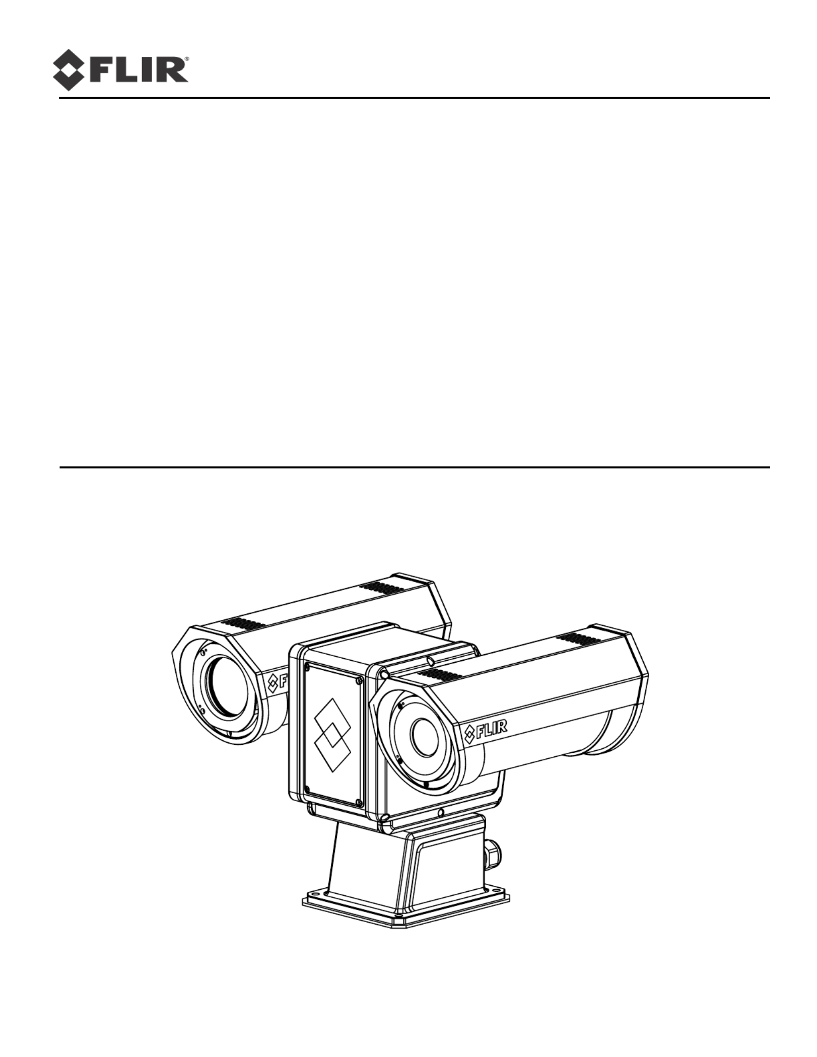
The PT-Series HD pan/tilt thermal security camera for medium- to long-range applications can be used
with traditional analog video installations or IP video networks. It incorporates a high-sensitivity thermal
camera with a choice of lenses and a long-range daylight camera all within a precision pan/tilt platform.
The PT-602CZ HD pairs a cooled mid-wave focal plane array (FPA) thermal detector with the daylight
camera.
This manual describes the installation of the PT-Series HD cameras. If help is needed during the
installation process, please refer to http://www.flir.com/security/display/?id=71083 for support. All
installers and integrators are encouraged to take advantage of the training offered by FLIR; visit
http://www.flir.com/training for more information.
This manual includes the following topics:
• Installation overview
• Mounting the camera and its components
• Connecting the electronics
• Bench testing the camera
• Configuration and operation of the camera
• Camera specifications
For safety, and to achieve the highest levels of performance from the camera system, follow the
warnings and cautions in this manual when handling and operating the camera system.
Warning!
Caution!
PT-Series Camera Mechanical Interface Control Document (ICD)
(FLIR Doc # 427-0075-XX-19)—available from the FLIR website, provides further details regarding
mechanical dimensions and mounting for the PT-Series HD camera.
Note
Nexus IP Camera Configuration Guide
(FLIR Doc # 427-0030-00-28)—Available from the FLIR website, provides further details on using a
web browser to configure PT-Series HD cameras.
If mounting the camera on a pole, tower or any elevated location, use industry standard safe
practices to avoid injuries.
Except as described in this manual, do not open the camera for any reason. Disassembly of the
camera (including removal of the cover) can cause permanent damage and will void the warranty.
Be careful not to leave fingerprints on the camera’s infrared optics.
The camera requires a power supply of 24 Volts nominal. Operating the camera outside of the
specified input voltage range or the specified operating temperature range can cause permanent
damage.
This manual has basic configuration information about the camera and making configuration
changes. Refer to the Nexus IP Camera Configuration Guide for more details.
427-0075-01-12 Version 110 November 2017 5
1 PT-Series HD Camera Installation
1.1 Camera Overview
The PT-Series HD camera is both an analog and an IP camera. The video from the camera can be
viewed over a traditional analog video network or it can be viewed by streaming it over an IP network
using MJPEG or H.264 encoding. Analog video will require a connection to a video monitor or an
analog matrix/switch. The IP video will require a connection to an Ethernet network switch and the
appropriate software for viewing the video stream.
1.2 Installation Overview
The PT-Series HD camera is intended to be mounted outdoors on a medium-duty fixed pedestal mount
or wall mount commonly used in the CCTV industry. Cables will exit from the back of the camera
housing. The mount must support up to 45 lbs (20 KG). The camera can be controlled through either
serial or IP communications. The camera operates on 21 Vac to 30 Vac or 21 Vdc to 30 Vdc. In order
to access the electrical connections and install the cables, it is necessary to temporarily remove the
back cover of the camera housing. Ensure the back cover is replaced in the same orientation, with the
two cable glands below the central pressure equalization vent.
1.2.1 Camera Connection Options
Camera connections are made through water-tight cable gland seals on the rear of the camera. Refer
to Cable Gland Sealing, pg. 16 to ensure the glands are used correctly and the connections are sealed.
Analog video will require at least one connection to a video monitor or an analog video matrix switch.
In most analog installations, two video connections will be used—one for the thermal camera video,
and one for the daylight camera video. The camera provides two BNC connectors for these analog
video channels.
An Ethernet connection is provided for IP video streaming and for command and control
communications using a web browser.
For analog installations that are not using Ethernet/IP, a serial cable (RS232 or RS422) can be
connected and used for command and control communications, supporting either Pelco D or Bosch
protocols. It is recommended an Ethernet cable should also be installed to allow easy remote access
for camera configuration, operation, and troubleshooting.
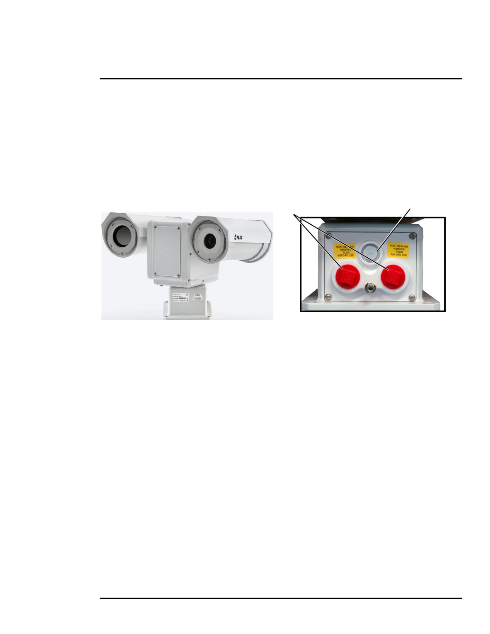
Figure 1-1: PT-Series HD
Shipping plugs only -
Remove before installing Vent

427-0075-01-12 Version 110 November 2017 6
1 PT-Series HD Camera Installation
1.2.2 Serial Communications Overview
The installer must decide if the serial communications settings will be configured via hardware (DIP
switch settings) or software (default). If the camera has an Ethernet connection, then generally it is
easier (and more convenient) to make configuration settings via software. Then configuration changes
can be made over the network without physically accessing the camera. Also the settings can be
saved to a file and backed up or restored as needed.
If the camera is configured via hardware, then configuration changes in the future may require
accessing the camera on a tower or pole, dismounting it, and removing the back and so on. If the
camera does not have an Ethernet connection, the DIP switches must be used to set the serial
communication options.
1.2.3 Supplied Components
The PT-Series HD camera ships with these standard components:
• Multi-sensor pan/tilt camera unit
• Galvanic isolation kit (PN 4204960)
• Noise suppression ferrite
• Cable glands and spare parts kit
1.2.4 Required Components
The installer will need to supply the following items; the cable lengths are specific to the installation.
• 24 Vdc or 24 Vac power supply
Note
• Electrical cables, for system power and heater power; 3-conductors are required for system power
(one ground) and two conductors are required for heater power (no ground). The wire gauge must
be determined by cable length and supply voltage. A single 5-conductor, shielded cable or two
individual cables may be used. Refer to Figure 1-4 on page 11 for additional information.
• Camera grounding strap
• Coaxial RG59U video cables and a 90° BNC adapter at the camera end for analog video
• Shielded CAT6 Ethernet cable for streaming video, control, and for software updates. CAT5e
Ethernet cable may be adequate in many installations except when closely installed with power
cables in demanding video streaming networks.
• Serial cable for serial communications—optional
• Miscellaneous electrical hardware, camera mount (with stainless steel washers and bolts),
connectors, and tools
A single ferrite is supplied with this equipment, the equipment was tested for compliance with the
FCC limits for a Class A digital device using the ferrite installed on the system power cable. When
connecting one or two power cables to the equipment, the supplied ferrite must be installed with this
equipment. A power installation using metal conduit does not require installing the ferrite.

427-0075-01-12 Version 110 November 2017 8
1 PT-Series HD Camera Installation
1.5.2 Earth Ground Connection
Earth ground connection is very important
to protect PT-series from surge induced
failures and corrosion caused by stray
current/ground loops. Attach ground wire
(16 AWG or larger) to ground lug on
access panel. Use the large hex nut to
secure ground wire to stud on access
panel. Ground stud is #8-32 thread.
Caution!
PT-Series HD cameras must be mounted upright on top of the mounting surface, with the base below
the camera. The unit should not be hung upside down.
When lifting the camera use the camera body and base, not the tubes.
Ground Lug
Figure 1-2: PT-Series HD Camera Mounting
Not to scale
0
0.295
All dimensions in inches
0
2X 3.17 ± .02
2X 3.21 ± .02
2X 2.72 ± .02
2X 2.72 ± .02
4X Ø.354 THRU
Pan Axis
Tilt Axis
Pan volume
minimum Ø25.5

427-0075-01-12 Version 110 November 2017 9
1 PT-Series HD Camera Installation
1.5.3 Installation of Camera and Galvanic Isolation Kit
Important Safeguards and Warnings
• Installation and servicing should be done by qualified installation and service personnel only.
• Installation should be done according to all local and national electrical and mechanical codes,
using only approved materials.
Warning!
• Once the mounting location has been selected, verify both sides of the mounting surface are
accessible and free of utility service lines or other obstructions.
• Use stainless steel hardware to fasten mounts to outdoor surfaces.
• Use a thread locking compound such as Loctite 242 or equivalent with all metal to metal threaded
connections.
• To prevent damage from water leakage when installing outdoors, apply sealant around the bolt
holes between the mount and the mounting surface.
Caution!
Step 1 Determine the correct positioning of the isolation plate (See Figure 1-3 on page 10).
Step 2 Place the isolation plate and the camera on the mounting structure aligning the bolt holes or
studs.
Step 3 Install nylon shoulder washers (4x) or nylon flat washers (4x) onto camera base.
If using nylon flat washers, apply a generous coat of Tef-Gel filling all gaps and voids.
Before drilling into walls or ceilings for mounting the camera, verify that areas behind these positions
do not contain electrical or other utility service lines. Serious injury or death may result from failure
to heed this warning.
Following this procedure is critical to maintaining the warranty on your PT-Series HD product.
Failure to follow these instructions can potentially void the camera warranty.
Table 1-1: Kit Contents
Description Qty
Isolation plate 1
M8 nylon flat washera
M8 nylon shoulder washer
a. Use the alternate nylon flat washers and Tef-Gel lubricant on fasteners for PT-Series HD camera bases
with mounting holes that are too small to accept the shoulder washers. A syringe of Tef-Gel will be supplied
in the mounting kit when the nylon flat washer is required.
6
6
Two extra pieces of each attaching part are
supplied in the kit.
M8 split washer, S.S. 6
M8 washer, S.S. 6
Tef-Gel TG .25, 3 cc syringeaoptional
427-0075-01-12 Version 110 November 2017 10
1 PT-Series HD Camera Installation
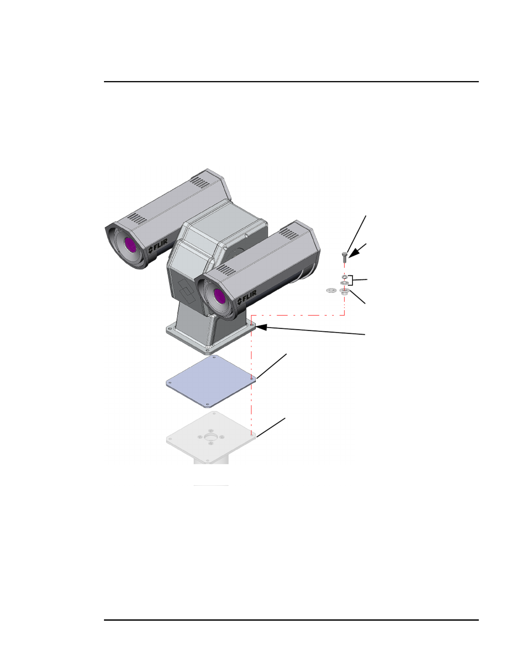
Step 4 Secure the camera using 5/16” or M8 fasteners (4x) with stainless steel flat washers and
split washers on top of the nylon washers.
Step 5 Ensure the camera is properly grounded. FLIR requires using a 14 AWG to 16 AWG
grounding strap anchored to the ground lug on the back plate of the camera housing and
then terminated to the nearest earth-grounding point.
M8 or 5/16” fasteners (not supplied)
4 places, minimum length 1 in.
M8 split lock washer (4 places)
M8 flat washer (4 places)
Figure 1-3: PT-Series HD Galvanic Isolation Kit (PN 4204960)
M8 nylon shoulder washer or
isolation plate
example mounting structure
(dependent on mounting structure)
nylon flat washer (4 places)
(FLIR PN 500-0461-00)
If using nylon flat washers,
apply a generous coat of Tef-Gel
If using nylon flat washers,
apply a generous coat of Tef-Gel
filling all gaps and voids.
filling all gaps and voids.
(4 places)
(4 places)

427-0075-01-12 Version 110 November 2017 12
1 PT-Series HD Camera Installation
1.6.2 Connecting power
The camera itself does not have an on/off switch. Generally a circuit breaker will be used to apply or
remove power to the camera. If power is supplied to it, the camera will be in one of two modes: Booting
Up or Powered On.
The power cables supplied by the installer must use wires that are sufficient size gauge (16 AWG
recommended) for the supply voltage and length of the cable run. Always follow local building codes!
To satisfy FCC requirements, the supplied noise suppression ferrite must be installed on the camera
system power cable unless power cables are enclosed in metal conduit. Refer to Figure .1-4
Note that the heater power cable requires two-wire power. Do not connect to the power supply ground.
Ensure the camera is properly grounded. Typical to good grounding practices, the camera chassis
ground should be provided using the lowest resistance path possible. FLIR requires using a grounding
strap anchored to the grounding lug on the back plate of the camera housing and connected to the
nearest earth-grounding point.
Note
The terminal blocks for power connections will accept a maximum 16 AWG wire size.
Gland A Camera End
Serial and IP Communications
Main Analog Video
Gland B Camera End
Auxiliary Analog Video and Power
EthernetSerial
Control
Male
BNC
Video
Ethernet
RS232
RS422
20 AWG MAX
RX+
TX+
GND
RD(A)-
GND
RD(B)+
TD(A)-
TD(B)+
12345
{
Main
Port
Back Cover
16 AWG Shielded
16 AWG Shielded Local
GND
24
VAC/DC
24
VAC/DC
1
2
3
1
2
3
24 VAC/DC+
24 VAC/DC-
Earth Ground
24 VAC/DC+
24 VAC/DC-
{
{
Chassis
GND
Video
Male
BNC
Auxiliary
Port
Heater
Power
Camera
Power
Heater
Power
Camera
Power
3/4” NPT for Cable
Gland or Conduit
Noise suppression
ferrite (supplied)
Figure 1-5: PT-Series HD Camera Connection Schematic

427-0075-01-12 Version 110 November 2017 14
1 PT-Series HD Camera Installation
1.6.6 Serial Communications Settings - Hardware DIP Switches
The camera has two blocks of DIP switches that are used to configure the serial communications
settings. One block of switches has 8 switches and is used to set the serial address (or ID) of the
camera. The other block of switches has 10 switches and is used to set baud rate, hardware protocol
(RS-232 or RS-422), serial protocol (Pelco D or Bosch), and Software Override.
The figure below shows the locations of dip switches SW102 and SW103.
When the Software Override DIP switch is set to the Off position (as it is by default), all of the other DIP
switches will be ignored, and configuration changes must be made through software. If the switch is
set to the On position, all configuration settings related to serial communications are made with the
DIP switches, and changes that are made via software (with a web browser) will be ignored.
Serial Address: Use the block of switches on the address of the left (SW102) to set the serial
camera. The available range of values is from decimal 1 to 255. The dip switches are interpreted as a
binary number, with switch 1 representing the least significant bit (the switches are in the reverse order
of the bits). For convenience, a table of serial addresses and their binary equivalents is included at the
end of the manual. Refer to Serial Address: Decimal To Binary Conversion, pg. 45
Table 1-2: Dip Switch Address/ID Settings—SW101
ID Sw 1
LSB Sw 2 Sw 3 Sw 4 Sw 5 Sw 7Sw 6 Sw 8
MSB
1 On OffOff Off Off Off OffOff
2 Off Off Off OffOn OffOff Off
3 On On OffOff Off Off OffOff
… … … … … … … … …
255 On On On On On OnOn On
Figure 1-6: PT-Series HD Serial Communications Configuration
SW102 SW103
Off
On
Switch
Position

427-0075-01-12 Version 110 November 2017 15
1 PT-Series HD Camera Installation
Other Serial Communication Parameters: The tables below defines the switch locations, bit
numbering and on/off settings used in controlling the other serial communication parameters.
Table 1-3: Dip Switch Settings—SW103
Settings Description
Baud rate: This is the baud rate of the system user serial
port. The available values are 2400, 4800, 9600, 19200
kbaud.
Bit 1 Bit 2
OFF OFF 2400
ON OFF 4800
OFF ON 9600
ON ON 19200
Camera Control Protocol: This is the communication
protocol selected for the system when operating over the
serial port. The available protocols are Pelco-D and
Bosch.
Bit 3 Bit 4
OFF OFF Pelco-D
ON OFF NA
OFF ON Bosch
ON ON NA
Serial Communication Standard: This determines the
electrical interface selected for the user serial port. The
available settings are RS422 and RS232.
Bit 5 Bit 6
OFF OFF NA
ON OFF RS422
OFF ON RS232
ON ON N/A
Not Used
Bit 7 Bit 8
X X
X X
X X
X X
Software Override DIP Switch: This setting determines
whether the system will use software settings for
configuration or if the dip switch settings will override the
software settings. Default is Off.
Bit 9
OFF Software select
ON Hardware select
Not Used Bit 10
X
427-0075-01-12 Version 110 November 2017 16
1 PT-Series HD Camera Installation
1.6.7 Cable Gland Sealing
Proper installation of cable sealing glands and use of appropriate elastomer inserts is critical to long
term reliability. Cables enter the camera mount enclosure through liquid-tight compression glands. Be
sure to insert the cables through the cable glands on the enclosure before terminating and connecting
them (the connectors will not fit through the cable gland). Leave the gland nuts loosened until all cable
installation has been completed. Inspect and install gland fittings in the back cover with suitable leak
sealant and tighten to ensure water tight fittings. Teflon tape or pipe sealant (for example DuPont
RectorSeal T™) are suitable for this purpose.
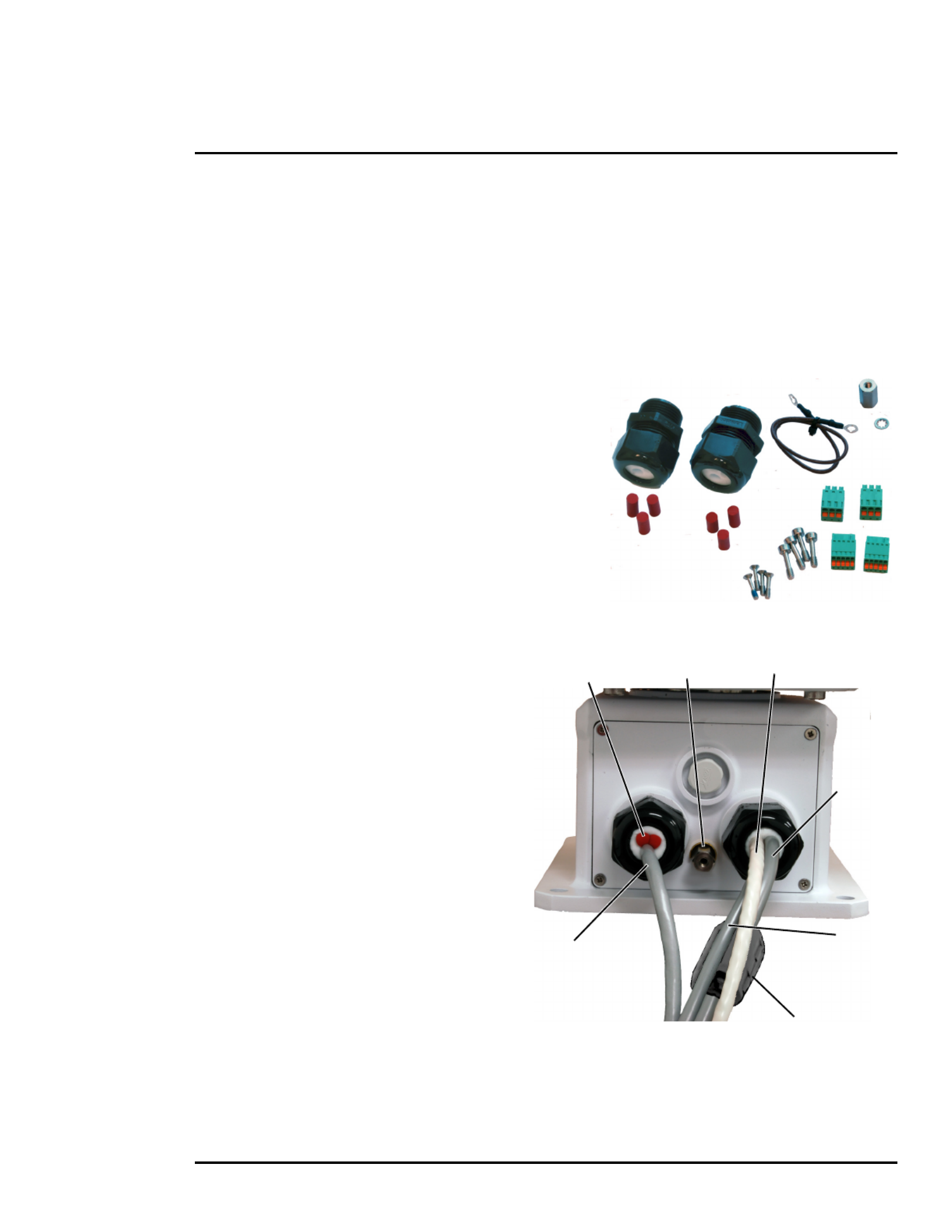
Cable Glands and Spare Parts Kit
The kit contains the two 3/4” cable glands and gland
seal plugs required for non-conduit installations.
The remaining parts included in the kit are:
• a spare ground wire
• a spare ground nut and lock washer
• two spare power terminal block plugs
• two spare serial port terminal block plugs
• four spare F-Series back cover screws
• four spare PT-Series back cover screws
Cable Gland Seal Inserts
Cables may be between 0.23" to 0.29" OD. Up
to six cables may be installed. Plugs are
required for the hole(s) not being used. The
photograph at the right shows two power
cables, an Ethernet cable, an analog video
cable, and two gland seal plugs.
If non-standard cable diameters are used, it
may be necessary to locate or fabricate the
appropriate insert to fit the desired cable. FLIR
Systems, Inc. does not provide cable gland
inserts other than what is supplied with the
system.
Camera
Ethernet
Analog video
Heater
Gland seal plugs
Ground
Lug
Power
Power
Ferrite on camera
power only

427-0075-01-12 Version 110 November 2017 21
2 Basic Operation and Configuration
Step 4 Select Assign IP to change the IP
address from the default DHCP to a static IP.
Step 5 Double-click the camera in DNA’s
Discovery List to open the camera’s web
server Login page in Internet Explorer or
point your web browser to the camera’s IP
address.
Step 6 Using a web browser, configure the camera
settings, such as camera date/time, and
other parameters, so the camera is
compatible with the existing network.
2.3 Log into the Camera Web Page
Use a web browser to connect to the camera’s web server using one of three User Names: user,
expert, or admin (the default passwords are user, expert, and admin respectively). The user login
can be used to do the initial bench test of the camera. The expert login may be used to make
configuration changes such as setting the IP address and other server settings. The admin login has
access to all configuration, setup, and maintenance settings. The login passwords should be changed
(admin login required) to prevent unauthorized access. Two web sessions can be active at once. An
inactive session will be logged out after 20 minutes.
For information on how to change the passwords, refer to Server > Security Options, pg. 35.
Open a web browser and enter the camera IP address. The login screen with a picture of the camera
will appear. Enter user for the User Name and user for the Password, and click Log in.

427-0075-01-12 Version 110 November 2017 27
2 Basic Operation and Configuration
Video
By default, two video streams are enabled for each camera: Video 0 and Video 1 are sourced from the
DLTV camera, Video 2 and Video 3 are sourced from the IR thermal imager. All video streams are
available for viewing from a client program such as FLIR Latitude, a stand-alone video player, or a
third-party VMS (including ONVIF systems).
To modify parameters that affect a particular IP Video stream from the camera, select the appropriate
link (for example, Video - 0).
The default parameters provide high-quality full frame-rate video streams with reasonable bandwidth
usage. In general, for most installations it will not be necessary to modify the default parameters. In
some cases, such as when a video stream is sent over a wireless network, it may be useful to adjust
the frame rate of the video stream to reduce the required bandwidth.
Select video format
427-0075-01-12 Version 110 November 2017 28
2 Basic Operation and Configuration
After making adjustments, scroll down to save the changes through power cycles.
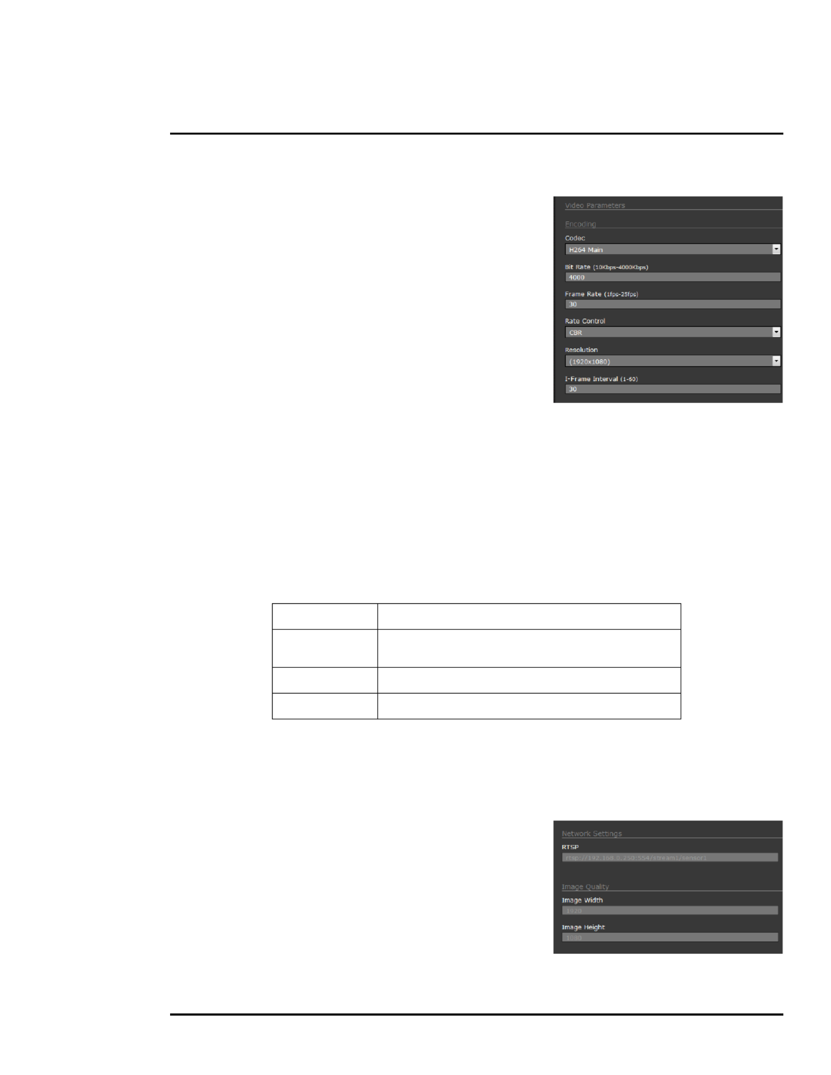
The parameters in the Encoding section will have a significant
impact on the quality and bandwidth requirements of the video
stream. In general it is recommended that the default values
are used initially, and then individual parameters can be
modified and tested incrementally to determine if the
bandwidth and quality requirements are met.
For the video streams, the Codec options are H.264 Main or
MJPEG.
The Bit Rate parameter is only used when the Rate Control
parameter is set to CBR (Constant Bit Rate). With the CBR
setting, the system attempts to keep the video at or near the
target bit rate.
The I-Frame Interval parameter controls the number of P-frames used between I-frames. I-frames are
full frames of video and the P-frames contain the changes that occurred since the last I-frame. A
smaller I-Frame Interval results in higher bandwidth (more full frames sent) and better video quality. A
higher I-Frame Interval number means fewer I-frames are sent and therefore results in possibly lower
bandwidth and possibly lower quality.
The Resolution parameter controls the video resolution and therefore can have a large impact on
bandwidth usage. The higher the resolution, the larger the size of the frame and the higher the
network bandwidth required. Table 2-1 provides the corresponding resolution for each setting.
If the video will be viewed on its own and on a reasonably large screen, a large image size setting may
look better. On the other hand, if the video is shown as a tile in a video wall, a smaller image size may
look as good and consume less bandwidth.
The default RTP Settings for connecting to an IP video stream
from the PT-Series HD are shown in the illustration. The RTP
Port and the Stream Name are used when establishing a
session from a client.
The connection string for each of the video streams are as
follows:
VIDEO 0 - rtsp://192.168.0.250:554/stream1/sensor1
VIDEO 1 - rtsp://192.168.0.250:554/stream2/sensor1
VIDEO 2 - rtsp://192.168.0.250:554/stream1/sensor2
VIDEO 3 - rtsp://192.168.0.250:554/stream2/sensor2
Ta b l e 2-1: Image Resolution Settingsa
a. Factory default resolution is shown in bold type.
VIDEO - 0 1920 x 1080, 1280 x 720, 640 x 480
VIDEO - 1 1920 x 1080, 1280 x 720, 720 x 480, 704 x 576, 640 x 480,
352 x 288, 320 x 240
VIDEO - 2 640 x 512, 320 x 256
VIDEO - 3 640 x 512, 640 x 480, 352 x 288, 320 x 256, 320 x 240
Specyfikacje produktu
| Marka: | Flir |
| Kategoria: | Kamera monitorująca |
| Model: | PT-606Z HD |
| Kolor produktu: | Biały |
| Rodzaj zasilania: | AC, DC |
| Napięcie wejściowe AC: | 24 V |
| Wysokość produktu: | 326 mm |
| Szerokość produktu: | 467 mm |
| Głębokość produktu: | 348 mm |
| Waga produktu: | 16400 g |
| Certyfikat środowiskowy (zrównoważonego rozwoju): | RoHS |
| Technologia łączności: | Przewodowa |
| Bluetooth: | Nie |
| Certyfikaty: | MIL-STD-810F\nIEC 60068-2-27\nFCC Part 15 (Subpart B, class A)\nCE, WEEE, ONVIF |
| Maksymalne zużycie mocy: | 195 W |
| Liczba kamer: | 1 |
| Formaty kompresji: | H.264, M-JPEG |
| Przeznaczenie: | Zewnętrzna |
| Ilość portów Ethernet LAN (RJ-45): | 1 |
| Zakres temperatur (eksploatacja): | -40 - 70 °C |
| Zakres wilgotności względnej: | 0 - 95 % |
| Zarządzanie przez stronę www: | Tak |
| Układ: | Pocisk |
| Automatyczne ustawienie ostrości: | Tak |
| Możliwość przybliżenia: | Tak |
| Tryb nocny: | Tak |
| Wi-Fi: | Nie |
| Przewodowa sieć LAN: | Tak |
| Zakres temperatur (przechowywanie): | -55 - 85 °C |
| Model: | Kamera bezpieczeństwa IP |
| Rodzaj opakowania: | Pudełko |
| Port RS-232: | 1 |
| Maks. rozdzielczość: | 640 x 480 px |
| Rodzaj interfejsu sieci Ethernet: | Fast Ethernet |
| Stopień ochrony IP: | IP66 |
| Zakres kąta nachylenia: | -90 - 90 ° |
| Typ mocowania: | Sufit / Ściana |
| Stosunek sygnału do szumu: | 120 dB |
| Obsługiwane protokoły sieciowe: | IPV4, HTTP, Bonjour, UPnP, DNS, NTP, RTSP, RTCP, RTP, TCP, UDP, ICMP, IGMP, DHCP, ARP, SCP |
| Długość ogniskowa: | 4.3 - 129 mm |
| Cyfrowe zbliżenie: | 12 x |
| Zespolony sygnał wizji: | 1 |
| Obsługa funkcji Plug & Play: | Tak |
| Redukcja hałasu: | Tak |
| Zdalnie sterowany: | Tak |
| Typ przetwornika obrazu: | CMOS |
| Suma megapikseli: | 0.3072 MP |
| Zoom optyczny: | 30 x |
| Tryb dzienny / nocny: | Tak |
| Kąt pola widzenia (FOV): | 24 ° |
| Min. Oświetlenie: | 0.01 lx |
| System formatu sygnału analogowego: | NTSC, PAL |
| Ostrość: | Zmotoryzowany/ręczny |
| Wbudowany HDD: | Nie |
| PTZ: | Tak |
| Wielkość czujnika CCD: | 1/2.8 " |
| Maksymalna przesłona: | 4.7 |
| Wide Dynamic Range (WDR): | Tak |
| Liczba czujników: | 1 |
| Wyjście prądu stałego (w woltach): | 24 |
| Zakres przesuwania: | 0 - 360 ° |
| Kompensacja oświetlenia tylnego: | Tak |
| Transmisja wideo: | Tak |
| Kontrola pochylenia kamery: | Tak |
| Szybkość pochylenia: | 30 °/s |
| Prędkość przesuwania: | 60 °/s |
| Minimalna przesłona: | 1.6 |
| Zaprogramowane punkty: | Tak |
| Kontrola panewki kamery: | Tak |
| Moduł termiczny: | Tak |
| Odświeżanie klatek termicznych (NTSC): | 30 Hz |
| Odświeżanie klatek termicznych (PAL): | 8.3 Hz |
| Porty RS-422: | 1 |
Potrzebujesz pomocy?
Jeśli potrzebujesz pomocy z Flir PT-606Z HD, zadaj pytanie poniżej, a inni użytkownicy Ci odpowiedzą
Instrukcje Kamera monitorująca Flir

13 Września 2024
13 Września 2024
13 Września 2024
12 Września 2024
11 Września 2024
11 Września 2024
11 Września 2024
11 Września 2024
10 Września 2024
9 Września 2024
Instrukcje Kamera monitorująca
- Kamera monitorująca Sony
- Kamera monitorująca Samsung
- Kamera monitorująca Tenda
- Kamera monitorująca Motorola
- Kamera monitorująca Stabo
- Kamera monitorująca Logitech
- Kamera monitorująca Xiaomi
- Kamera monitorująca Braun
- Kamera monitorująca Pioneer
- Kamera monitorująca TP-Link
- Kamera monitorująca Philips
- Kamera monitorująca Bosch
- Kamera monitorująca Gigaset
- Kamera monitorująca Hikvision
- Kamera monitorująca EZVIZ
- Kamera monitorująca Conceptronic
- Kamera monitorująca Panasonic
- Kamera monitorująca Canon
- Kamera monitorująca Crestron
- Kamera monitorująca Withings
- Kamera monitorująca Asus
- Kamera monitorująca Nedis
- Kamera monitorująca AG Neovo
- Kamera monitorująca Reolink
- Kamera monitorująca Boss
- Kamera monitorująca TRENDnet
- Kamera monitorująca Marquant
- Kamera monitorująca Toshiba
- Kamera monitorująca D-Link
- Kamera monitorująca August
- Kamera monitorująca Niceboy
- Kamera monitorująca Ring
- Kamera monitorująca Garmin
- Kamera monitorująca Imou
- Kamera monitorująca Blaupunkt
- Kamera monitorująca Grundig
- Kamera monitorująca APC
- Kamera monitorująca Honeywell
- Kamera monitorująca BLOW
- Kamera monitorująca Manhattan
- Kamera monitorująca Strong
- Kamera monitorująca Swann
- Kamera monitorująca Kwikset
- Kamera monitorująca Kodak
- Kamera monitorująca Cisco
- Kamera monitorująca ORNO
- Kamera monitorująca Broan
- Kamera monitorująca Moxa
- Kamera monitorująca Synology
- Kamera monitorująca Gembird
- Kamera monitorująca ZTE
- Kamera monitorująca Turing
- Kamera monitorująca Lindy
- Kamera monitorująca Minox
- Kamera monitorująca Zebra
- Kamera monitorująca DSC
- Kamera monitorująca JVC
- Kamera monitorująca ZyXEL
- Kamera monitorująca Trust
- Kamera monitorująca LogiLink
- Kamera monitorująca Furrion
- Kamera monitorująca Linksys
- Kamera monitorująca Google
- Kamera monitorująca Digitus
- Kamera monitorująca Vimar
- Kamera monitorująca V-TAC
- Kamera monitorująca Dahua Technology
- Kamera monitorująca Schneider
- Kamera monitorująca Eufy
- Kamera monitorująca Ricoh
- Kamera monitorująca Emos
- Kamera monitorująca AVMATRIX
- Kamera monitorująca Renkforce
- Kamera monitorująca Rollei
- Kamera monitorująca Marshall
- Kamera monitorująca Perel
- Kamera monitorująca Somfy
- Kamera monitorująca Uniden
- Kamera monitorująca Netgear
- Kamera monitorująca Thomson
- Kamera monitorująca DiO
- Kamera monitorująca Velleman
- Kamera monitorująca Ferguson
- Kamera monitorująca DataVideo
- Kamera monitorująca Delta Dore
- Kamera monitorująca Pyle
- Kamera monitorująca Intellinet
- Kamera monitorująca CRUX
- Kamera monitorująca Setti+
- Kamera monitorująca Waeco
- Kamera monitorująca Vivotek
- Kamera monitorująca Vtech
- Kamera monitorująca Speco Technologies
- Kamera monitorująca EtiamPro
- Kamera monitorująca Edimax
- Kamera monitorująca Petcube
- Kamera monitorująca ION
- Kamera monitorująca First Alert
- Kamera monitorująca AirLive
- Kamera monitorująca Maginon
- Kamera monitorująca EnGenius
- Kamera monitorująca SPC
- Kamera monitorująca Planet
- Kamera monitorująca Brilliant
- Kamera monitorująca Genie
- Kamera monitorująca LevelOne
- Kamera monitorująca Axis
- Kamera monitorująca Sanyo
- Kamera monitorująca Lorex
- Kamera monitorująca Control4
- Kamera monitorująca Milesight
- Kamera monitorująca Aluratek
- Kamera monitorująca Abus
- Kamera monitorująca Elro
- Kamera monitorująca Olympia
- Kamera monitorująca Hama
- Kamera monitorująca Marmitek
- Kamera monitorująca Ubiquiti Networks
- Kamera monitorująca Western Digital
- Kamera monitorująca Netatmo
- Kamera monitorująca Schwaiger
- Kamera monitorująca Promise Technology
- Kamera monitorująca GVI Security
- Kamera monitorująca AVer
- Kamera monitorująca ZKTeco
- Kamera monitorująca Netis
- Kamera monitorująca Extech
- Kamera monitorująca Denver
- Kamera monitorująca Anker
- Kamera monitorująca Allnet
- Kamera monitorująca Marshall Electronics
- Kamera monitorująca Orion
- Kamera monitorująca Yale
- Kamera monitorująca SereneLife
- Kamera monitorująca Ernitec
- Kamera monitorująca AVerMedia
- Kamera monitorująca MEE Audio
- Kamera monitorująca Genius
- Kamera monitorująca Trevi
- Kamera monitorująca Technaxx
- Kamera monitorująca Atlona
- Kamera monitorująca Hanwha
- Kamera monitorująca Overmax
- Kamera monitorująca Quantum
- Kamera monitorująca Y-cam
- Kamera monitorująca Grandstream
- Kamera monitorująca Raymarine
- Kamera monitorująca Powerfix
- Kamera monitorująca Avanti
- Kamera monitorująca Ikan
- Kamera monitorująca Alecto
- Kamera monitorująca Avidsen
- Kamera monitorująca JUNG
- Kamera monitorująca Burg Wächter
- Kamera monitorująca Foscam
- Kamera monitorująca Lumens
- Kamera monitorująca Monacor
- Kamera monitorująca Dörr
- Kamera monitorująca M-e
- Kamera monitorująca EVE
- Kamera monitorująca Smartwares
- Kamera monitorująca Adj
- Kamera monitorująca Qian
- Kamera monitorująca Arenti
- Kamera monitorująca Elmo
- Kamera monitorująca Vitek
- Kamera monitorująca Alfatron
- Kamera monitorująca UniView
- Kamera monitorująca Clas Ohlson
- Kamera monitorująca Laserliner
- Kamera monitorująca Megasat
- Kamera monitorująca REVO
- Kamera monitorująca BZBGear
- Kamera monitorująca BirdDog
- Kamera monitorująca KJB Security Products
- Kamera monitorująca HiLook
- Kamera monitorująca Profile
- Kamera monitorująca Aldi
- Kamera monitorująca Aritech
- Kamera monitorująca Acti
- Kamera monitorująca ACME
- Kamera monitorująca Flamingo
- Kamera monitorująca Caliber
- Kamera monitorująca Eminent
- Kamera monitorująca Sitecom
- Kamera monitorująca Exibel
- Kamera monitorująca Fortinet
- Kamera monitorująca KlikaanKlikuit
- Kamera monitorująca Trebs
- Kamera monitorująca Ednet
- Kamera monitorująca Steren
- Kamera monitorująca Buffalo
- Kamera monitorująca Arlo
- Kamera monitorująca Nest
- Kamera monitorująca Siedle
- Kamera monitorująca Hive
- Kamera monitorująca Switel
- Kamera monitorująca Chacon
- Kamera monitorująca InFocus
- Kamera monitorująca Hombli
- Kamera monitorująca Naxa
- Kamera monitorująca Konig
- Kamera monitorująca Valueline
- Kamera monitorująca BRK
- Kamera monitorująca QSC
- Kamera monitorująca Xavax
- Kamera monitorująca Vaddio
- Kamera monitorująca Gira
- Kamera monitorująca Interlogix
- Kamera monitorująca Boyo
- Kamera monitorująca IC Intracom
- Kamera monitorująca Iget
- Kamera monitorująca EverFocus
- Kamera monitorująca Adesso
- Kamera monitorująca Satel
- Kamera monitorująca POSline
- Kamera monitorująca Notifier
- Kamera monitorująca Hawking Technologies
- Kamera monitorująca Friedland
- Kamera monitorująca Nexxt
- Kamera monitorująca Monoprice
- Kamera monitorująca Watec
- Kamera monitorująca Beafon
- Kamera monitorująca Chuango
- Kamera monitorująca ETiger
- Kamera monitorująca Videcon
- Kamera monitorująca INSTAR
- Kamera monitorująca Provision ISR
- Kamera monitorująca Aqara
- Kamera monitorująca Advantech
- Kamera monitorująca Digital Watchdog
- Kamera monitorująca Ganz
- Kamera monitorująca AViPAS
- Kamera monitorująca ClearOne
- Kamera monitorująca Ebode
- Kamera monitorująca Oplink
- Kamera monitorująca Sonic Alert
- Kamera monitorująca Linear PRO Access
- Kamera monitorująca Summer Infant
- Kamera monitorująca SMC
- Kamera monitorująca Topica
- Kamera monitorująca Kogan
- Kamera monitorująca Iiquu
- Kamera monitorująca Verint
- Kamera monitorująca Brinno
- Kamera monitorująca Rostra
- Kamera monitorująca Caddx
- Kamera monitorująca Spyclops
- Kamera monitorująca EKO
- Kamera monitorująca Kguard
- Kamera monitorująca Woonveilig
- Kamera monitorująca Mobi
- Kamera monitorująca Surveon
- Kamera monitorująca Hollyland
- Kamera monitorująca Epcom
- Kamera monitorująca Indexa
- Kamera monitorująca Lutec
- Kamera monitorująca Whistler
- Kamera monitorująca ClearView
- Kamera monitorująca VideoComm
- Kamera monitorująca IMILAB
- Kamera monitorująca 3xLOGIC
- Kamera monitorująca Pelco
- Kamera monitorująca Leviton
- Kamera monitorująca Inkovideo
- Kamera monitorująca Pentatech
- Kamera monitorująca Weldex
- Kamera monitorująca SecurityMan
- Kamera monitorująca Canyon
- Kamera monitorująca CNB Technology
- Kamera monitorująca Tapo
- Kamera monitorująca Aigis
- Kamera monitorująca Exacq
- Kamera monitorująca Brickcom
- Kamera monitorująca Laxihub
- Kamera monitorująca Securetech
- Kamera monitorująca EFB Elektronik
- Kamera monitorująca NetMedia
- Kamera monitorująca Videotec
- Kamera monitorująca Illustra
- Kamera monitorująca Nivian
- Kamera monitorująca E-bench
- Kamera monitorująca Syscom
- Kamera monitorująca Tecno
- Kamera monitorująca Night Owl
- Kamera monitorująca Guardzilla
- Kamera monitorująca Astak
- Kamera monitorująca Blink
- Kamera monitorująca Milestone Systems
- Kamera monitorująca Zavio
- Kamera monitorująca Campark
- Kamera monitorująca IPX
- Kamera monitorująca Dedicated Micros
- Kamera monitorująca Hamlet
- Kamera monitorująca Annke
- Kamera monitorująca AVTech
- Kamera monitorująca Qoltec
- Kamera monitorująca Approx
- Kamera monitorująca Digimerge
- Kamera monitorująca Wisenet
- Kamera monitorująca Infortrend
- Kamera monitorująca Epiphan
- Kamera monitorująca Mach Power
- Kamera monitorująca Compro
- Kamera monitorująca Aida
- Kamera monitorująca Ikegami
- Kamera monitorująca Accsoon
- Kamera monitorująca Vimtag
- Kamera monitorująca Gewiss
- Kamera monitorująca Alula
- Kamera monitorująca Insteon
- Kamera monitorująca Costar
- Kamera monitorująca ALC
- Kamera monitorująca Security Labs
- Kamera monitorująca Comtrend
- Kamera monitorująca Seneca
- Kamera monitorująca Avigilon
- Kamera monitorująca American Dynamics
- Kamera monitorująca Vosker
- Kamera monitorująca Sentry360
- Kamera monitorująca Bea-fon
- Kamera monitorująca Owltron
- Kamera monitorująca Enabot
- Kamera monitorująca Luis Energy
- Kamera monitorująca Sir Gawain
- Kamera monitorująca VisorTech
- Kamera monitorująca Atlantis Land
- Kamera monitorująca B & S Technology
- Kamera monitorująca I3International
- Kamera monitorująca IDIS
- Kamera monitorująca Ecobee
- Kamera monitorująca Conbrov
- Kamera monitorująca HuddleCamHD
- Kamera monitorująca Mobotix
- Kamera monitorująca IOIO
- Kamera monitorująca BIRDFY
- Kamera monitorująca I-PRO
- Kamera monitorująca DVDO
- Kamera monitorująca TCP
- Kamera monitorująca Bolin Technology
- Kamera monitorująca Nextech
Najnowsze instrukcje dla Kamera monitorująca
28 Stycznia 2025
25 Stycznia 2025
15 Stycznia 2025

13 Stycznia 2025

13 Stycznia 2025
13 Stycznia 2025

12 Stycznia 2025
12 Stycznia 2025
12 Stycznia 2025
12 Stycznia 2025