Instrukcja obsługi Draytek Vigor 2500V
Przeczytaj poniżej 📖 instrukcję obsługi w języku polskim dla Draytek Vigor 2500V (185 stron) w kategorii router. Ta instrukcja była pomocna dla 13 osób i została oceniona przez 2 użytkowników na średnio 4.5 gwiazdek
Strona 1/185


Preamble of Vigor2500V series 1
Preamble of Vigor2500V/Vi series ADSL
VoIP Routers
1. Benefits of Vigor2500V series
ADSL router for sharing your Internet connection
Robust firewall to help protect your computers
Make / Receive Voice calls over your ADSL connection using a regular
telephone handset
Integration with your existing phone line (POTS) with automatic failover
during power cuts
Free Voice-over-IP phone calls to other VoIP users
ISDN backup/remote access/ISDN loop through are available on
Vigor2500Vi series which have ISDN interface
Compatible with Windows and Mac OS
Preamble of Vigor2500V series 2
1.1 Brief Overview
Vigor2500V Vigor2500Vi
ADSL Router * *
VoIP * *
PSTN life line * *
ISDN loop through - *
ISDN backup - *
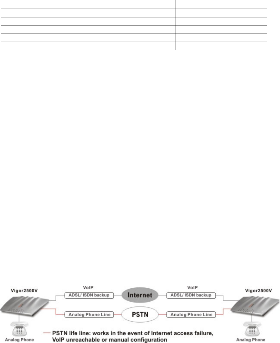
What does "PSTN life line" and "ISDN loop through" perform on
Vigor2500V series?
The Vigor2500V has a “Line” port on the rear panel for connecting to a PSTN
(regular analogue) line. The Loop Through option can be used to set an
alternate telephone number for your contact on the PSTN, which the
Vigor2500V will dial instead of the SIP account if you lose ADSL access or
power to the Vigor2500V. Hence, the PSTN line can act as a lifeline (backup
mechanism) for VoIP calls. The lifeline mechanism is activated automatically
but can also be manually configured.
Because there is ISDN interface on the Vigor2500Vi series, you can use the
ISDN line as phone line as well as Internet remote access/dial back-up for
ADSL. You will be able to still make ISDN phone calls if the router loses power
or the VoIP calls can not make as Internet access is broken. Hence, the ISDN
line can also be lifeline (backup mechanism) for VoIP calls.

Preamble of Vigor2500V series 3
Annex- A countries:
Annex – B countries
Preamble of Vigor2500V series 4
1.2 Highlights
VoIP
G.168 Line Echo-cancellation
Gain Control
Jitter Buffer (250ms)
Voice CODEC: G.711 A/u law, G.729
A/B, VAD/CNG
Tone Generation and Detection: DTMF,
Dial, Busy, Ring Back
Protocol: SIP, RTP/RTCP
ADSL
Compatible with ADSL lines up to 8
Mbps.
Support PPPoE, PPPoA, MPoA
LAN
4 port 10/100 Base-TX Ethernet switch
DHCP server for IP assignment (up to
253 users)
DNS cache and proxy
Network Features
DHCP server / relay
Dynamic DNS
Call Scheduling
Firewall
Stateful Packet Inspection
Selectable DoS/DDoS protection
IP address anti-spoofing
User-configurable packet filtering
NAT/PAT with Port
Forwarding/Redirection & DMZ
E-mail alerting mechanism
E-mail Detection
Detect user-defined e-mails and hold
them in mail server (POP3).
Flexible URL Content Filtering
URL blocking by user-defined keywords
Preclude web surfing from using directly
IP address
Java/ActiveX/cookies/proxy blocking
Executable/compressed/multimedia files
blocking
Time schedule support
Application Support
Windows Messenger, Yahoo Messenger,
MSN Messenger V6.0, NetMeeting,
ICQ2001b/2002a, most online gaming,
and other multimedia applications
UPnP protocol support
Router Management
Web-based User Interface
Command line interface (Telnet)
Telnet remote access support
Built-in diagnostic tools
Quick Start Wizard
Attack alert by e-mail
Syslog Monitoring
ISDN Facilities (for Vigor2500Vi only)
Compatible with Euro ISDN
Automatic ISDN backup
Support for 64/128kbps (multilink-PPP)
Bandwidth on demand (automatically
switches between 64kbps and 128kbps)
LAN-to-LAN connectivity
Remote Activation
Virtual TA
Routing Support
RIPv2 (not applicable to the UK)
Static Route (not applicable to the UK)

Preamble of Vigor2500V series 5
Robust Firewall:
E-mail Detection:
Peer to Peer VoIP communications:

Preamble of Vigor2500V series 6
Vigor2500V series with the services of ITSP:
Before you can set up the router for SIP you need to open an account with a
SIP registrar [e.g. IPTEL, DrayTEL (www.draytel.org)].
Preamble of Vigor2500V series 7
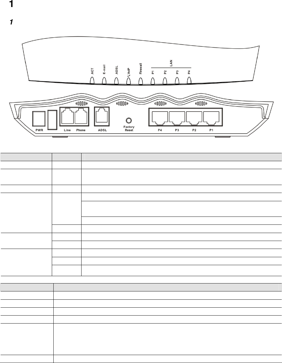
1.3 Front Panel LEDs and Rear Panel Interfaces
1.3.1 Vigor2500V
LED
Status Explanation
ACT (Activity) blinking
The router is powered on and running properly.
E-mail blinking
When detecting one or more user-defined e-mails existing on
mail server.
ADSL on The ADSL line is showtime.
Solid light when the handset of phone is picked up (off hooked).
Blinking per 0.3 second when phone call is via ISDN loop
through.
green
Blinking per 2 seconds when phone is connected through VoIP.
VoIP
orange
Solid light when phone call is via PSTN life line.
on The firewall function is active.
Firewall blinking
When encountering DoS attacks.
green A normal 100Mbps connection is through its corresponding port.
orange
A normal 10Mbps connection is through its corresponding port.
LAN
(P1, P2, P3, P4)
blinking
Ethernet packets are transmitting.
Interface
Description
PWR Connect the included power adapter to the power outlet.
Line Connect to the analog phone line for PSTN life line.
Phone Connect to the analog phone for VoIP communication.
ADSL Connect the ADSL line to access the Internet.
Factory Reset
Restore the default settings. Usage: Turn on the router (ACT LED is
blinking), press the hole and keep for more than 5 seconds. When the ACT
LED begins to blink rapidly, release the button. Then the router will restart
with the factory default configuration.
P1, P2, P3, P4
Connect to the local network devices.

Preamble of Vigor2500V series 8
1.3.2 Vigor2500Vi
LED
Status
Explanation
ACT (Activity) blinking
The router is powered on and running properly.
on The ISDN network is correctly setup.
ISDN/E-mail blinking
When detecting one or more user-defined e-mails existing on
mail server.
ADSL on The ADSL line is showtime.
Solid light when the handset of phone is picked up (off hooked).
Blinking per 0.3 second when phone call is via ISDN loop
through.
green
Blinking per 2 seconds when phone is connected through VoIP.
VoIP
orange
Solid light when phone call is via PSTN life line.
on The firewall function is active.
Firewall blinking
When encountering DoS attacks.
green A normal 100Mbps connection is through its corresponding
port.
orange
A normal 10Mbps connection is through its corresponding port.
LAN
(P1, P2, P3, P4)
blinking
Ethernet packets are transmitting.
Interface
Description
PWR Connect the included power adapter to the power outlet.
Line Connect to the analog phone line for PSTN life line.
Phone Connect to the analog phone for VoIP communication.
ADSL Connect the ADSL line to access the Internet.
Factory Reset
Restore the default settings. Usage: Turn on the router (ACT LED is
blinking), press the hole and keep for more than 5 seconds. When the
ACT LED begins to blink rapidly, release the button. Then the router will
restart with the factory default configuration.
P1, P2, P3, P4
Connect to the local network devices.
ISDN Connected to an external NT1(or NT1+) box provided by your ISDN
service provider.

Preamble of Vigor2500V series 9
1.4 Package Contents
Quick Installation Guide
CD (Manual and Utilities)
UK-type power adapter
EU-type power adapter
USA/Taiwan-type power adapter AU/NZ-type power adapter
RJ-45 (Ethernet)
RJ-11 to RJ-11 (Annex A / B)
RJ-11 to RJ-45 (Annex B) RJ-45 to RJ-45 (ISDN)
(for Vigor2500Vi only)
Preamble of Vigor2500V series 10
2. Hardware Installation of Your Vigor2500V/Vi Router
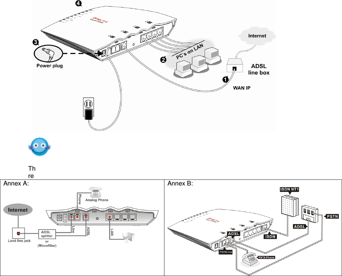
2.1 Hardware Installation
Before starting to configure the router, you have to connect your devices correctly.
1. Connect the ADSL interface to the external splitter with a RJ-11 cable.
2. Connect one port of 4-port switch to your computer with a RJ-45 cable.
3. Connect the attached power adapter to the power port.
4. Check the ACT, ADSL and LAN LEDs to assure network connections.
(Regarding detailed LED status explanation please refer to section 1.3)
Connection scenario is shown as below:
The splitter or microfilter is the optional accessories.
There are some variant connection in Annex A and Annex B countries. Followings are more
reference for you:
Annex A:
Annex B:

Vigor2500V series ADSL VoIP Router
i
About This User’s Manual
This manual is designed to assist users in using the Vigor2500V of Internet
security routers. Information in this document has been carefully checked for
accuracy and, however, no guarantee is given as to the correctness of the
contents. The information contained in this document is subject to change
without notice. Should you have any inquiries, please feel free to contact our
support via E-mail, Fax or phone. For the latest product information and
features, please visit our website at www.draytek.com.
We apply the sunshine-smile face of VigorBoy to some chapters in
order to remind you of your special attention! Should you have any queries
and suggestions, please do not hesitate to contact your local dealer or us via
support@draytek.com or info@draytek.com!

Vigor2500V series ADSL VoIP Router
iii
DrayTek Limited Warranty
We warrant to the original end user (purchaser) that the routers will be free
from any defects in workmanship or materials for a period of three (3) years
from the date of purchase from the dealer. Please keep your purchase
receipt in a safe place as it serves as proof of date of purchase.
During the warranty period, and upon proof of purchase, should the product
have indications of failure due to faulty workmanship and/or materials, we will,
at our discretion, repair or replace the defective products or components,
without charge for either parts or labor, to whatever extent we deem necessary
to restore the product to proper operating condition. Any replacement will
consist of a new or remanufactured functionally equivalent product of equal
value, and will be offered solely at our discretion. This warranty will not apply
if the product is modified, misused, tampered with, damaged by an act of God,
or subjected to abnormal working conditions.
The warranty does not cover the bundled or licensed software of other vendors.
Defects which do not significantly affect the usability of the product will not be
covered by the warranty.
We reserve the right to revise the manual and online documentation and to
make changes from time to time in the contents hereof without obligation to
notify any person of such revision or changes.

Vigor2500V series ADSL VoIP Router
iv
Be a Registered Owner
Online web registration at www.draytek.com is preferred. Alternatively, fill in
the registration card and mail it to the address found on the reverse side of the
card. Registered owners will receive future product and update information.

Vigor2500V series ADSL VoIP Router
v
Safety Instructions
Please read the installation guide thoroughly before you set up the router.
The router is a complicated electronic device that may be repaired only be
authorized and qualified personnel. Do not try to open or repair the
router yourself.
Do not place the router in a damp or humid place, e.g. a bathroom.
The router should be used in a sheltered area, within a temperature range
from +5 to +40 Celsius.
Do not expose the router to direct sunlight or other heat sources. The
housing and electronic components may be damaged by direct sunlight or
heat sources.
Keep the package out of reach of children.
When you would like to dispose of the router, please follow the local
regulations on conservation of the environment.

Vigor2500V series ADSL VoIP Router
vi
European Community Declarations
Manufacturer: DrayTek Corp.
Address: No. 26, Fu Shing Road, HuKou County, HsinChu
Industrial Park, Hsin-Chu, Taiwan 303
Product: Vigor2500V Series ADSL VoIP Routers
DrayTek Corp. declares that Vigor2500V series of routers are in
compliance with the following essential requirements and other
relevant provisions of R&TTE Directive 1999/5/EEC.
The product conforms to the requirements of Electro-Magnetic
Compatibility (EMC) Directive 89/336/EEC by complying with the
requirements set forth in EN55022/Class B and EN55024/Class B.
The product conforms to the requirements of Low Voltage (LVD)
Directive 73/23/EEC by complying with the requirements set forth in
EN60950.
The ISDN interface of Vigor2500Vi series is designed for the
Euro-ISDN network throughout the EC-region and where
Telcos/ISPs are also adopting Euro-ISDN to their ISDN services.

Vigor2500V series ADSL VoIP Router
vii
Commission (FCC) Interference
Statement
The Vigor2500V series have been tested and found to comply with
the limits for a Class B digital device, pursuant to part 15 of the FCC
Rules. Operation is subject to the following two conditions:
(1) this device may not cause harmful interference, and (2) this
device must accept any interference received, including
interference that may cause undesired operation. Class B limits
are designed to provide reasonable protection against harmful
interference in a residential installation. This equipment
generates, uses, and can radiate radio frequency energy, and,
if not installed and used in accordance with the instructions,
may cause harmful interference to radio communications.
However, there is not guarantee that interference will not occur
in a particular installation. If this equipment does cause harmful
interference to radio or television reception, which can be
determined by turning the equipment off and on, the user is
encouraged to try to correct the interference by one or more of
the following measures:
• Reorient the receiving antenna.
• Increase the separate between the equipment and the
receiver.
• Connect the equipment into an outlet on a circuit
different from that to which the receiver is connected.
• Consult the dealer or an experienced radio/TV technician
for help.

Vigor2500V series ADSL VoIP Router
viii
Customer Support
Please prepare the following information as you contact your customer
support.
Product model and serial number,
Warranty information,
Date that you received your router,
Brief description of your problem,
Steps that you may take to solve it and their associated SysLog
messages.
The information of customer support and sales representatives are
support@draytek.com and sales@draytek.com, respectively.

Vigor2500V series ADSL VoIP Router
ix
Table of Contents
CHAPTER 1. Quick Start Wizard ............................................................1-1
Introduction -----------------------------------------------------------------------1-1
Quick Start Wizard from Web Configurator----------------------------------1-2
Quick Start Wizard from Router Tools on CD-------------------------------1-4
Automatic QoS for VoIP applications-----------------------------------------1-5
CHAPTER 2. Online Status ...................................................................2-1
System status-----------------------------------------------------------------------2-2
LAN status---------------------------------------------------------------------------2-2
WAN status--------------------------------------------------------------------------2-2
ISDN status--------------------------------------------------------------------------2-3
ADSL status-------------------------------------------------------------------------2-4
CHAPTER 3. Internet Access Setup .....................................................3-1
PPPoE/PPPoA -------------------------------------------------------------------3-2
MPoA----------------------------------------------------------------------------------3-3
MultiPVC------------------------------------------------------------------------------3-5
Check Online Status---------------------------------------------------------------3-6
CHAPTER 4. LAN TCP/IP and DHCP Setup .........................................4-1
DHCP Server configuration------------------------------------------------------4-4
DNS operation-----------------------------------------------------------------------4-5
CHAPTER 5. NAT Setup ..........................................................................5-1
Introduction -----------------------------------------------------------------------5-1
NAT Setup---------------------------------------------------------------------------5-2
Setting of Port Redirection Table ----------------------------------------------5-3
Setting of DMZ Host Table ------------------------------------------------------5-5

Vigor2500V series ADSL VoIP Router
xi
CHAPTER 10. UPnP Setup....................................................................10-1
Introduction ---------------------------------------------------------------------10-1
Configuration ---------------------------------------------------------------------10-2
ALG's (Application Level Gateways)----------------------------------------10-4
CHAPTER 11. E-mail Detection ............................................................11-1
Introduction ---------------------------------------------------------------------11-1
Configuration ---------------------------------------------------------------------11-2
CHAPTER 12. VoIP ................................................................................12-1
Introduction ---------------------------------------------------------------------12-1
Automatic QoS for VoIP applications----------------------------------------12-2
VoIP_DialPlan Settings ---------------------------------------------------------12-3
VoIP_LoopThrough (lifeline) Settings ---------------------------------------12-4
Automatic PSTN_LoopThrough (lifeline) Settings -----------------------12-5
Automatic ISDN_LoopThrough Settings ---------------------------------12-5
Manual PSTN_LoopThrough (lifeline) Settings ---------------------------12-6
Manual ISDN_LoopThrough Settings -------------------------------------12-6
SIP Related Settings ------------------------------------------------------------12-7
Codec/RTP/DTMF Settings ---------------------------------------------------12-9
Example of "Peer to Peer" ---------------------------------------------------12-10
Example of "Calling via SIP server" [via ITSP services]---------------12-11
Voip Call Status------------------------------------------------------------------12-12
CHAPTER 13. ISDN (only for Vigor2500Vi series) ..............................13-1
Introduction ---------------------------------------------------------------------13-1
Configuration----------------------------------------------------------------------13-1
CHAPTER 14. Virtual TA (only for Vigor2500Vi series) ......................14-1
Introduction ---------------------------------------------------------------------14-1
Installing VTA client -------------------------------------------------------------14-2
Configuration of VTA client and Server-------------------------------------14-3

Vigor2500V series ADSL VoIP Router
xii
CHAPTER 15. Call Control (only for Vigor2500Vi series)...................15-1
Introduction ---------------------------------------------------------------------15-1
Configuration----------------------------------------------------------------------15-2
CHAPTER 16. System Status................................................................16-1
Introduction ---------------------------------------------------------------------16-1
Firmware of Router--------------------------------------------------------------16-2
Firmware of ADSL Modem chipset ------------------------------------------16-2
CHAPTER 17. Configuration Backup...................................................17-1
Introduction ---------------------------------------------------------------------17-1
BackUp Configuration-----------------------------------------------------------17-1
Restore Configuration ----------------------------------------------------------17-3
CHAPTER 18. Syslog ............................................................................18-1
Introduction ---------------------------------------------------------------------18-1
Configuration----------------------------------------------------------------------18-2
Example of Configuration -----------------------------------------------------18-3
CHAPTER 19. Time Setup.....................................................................19-1
Introduction ---------------------------------------------------------------------19-1
Configuration----------------------------------------------------------------------19-2
Set Time Clock via Web Configurator (adopt computer time) --------19-2
Set Time Clock via Internet (adopt Time Server)-------------------------19-3
CHAPTER 20. Management Setup .......................................................20-1
Introduction ---------------------------------------------------------------------20-1
Configuration----------------------------------------------------------------------20-2
Configuration of Access Control----------------------------------------------20-3
Configuration of Management Port------------------------------------------20-4

Vigor2500V series ADSL VoIP Router
xiii
CHAPTER 21. Reboot System and Firmware Upgrade(TFTP Server) ..21
Introduction ---------------------------------------------------------------------21-1
Reboot System-------------------------------------------------------------------21-1
Firmware Upgrade (TFTP Server)-------------------------------------------21-2
CHAPTER 22. Diagnostic Tools ...........................................................22-1
Introduction ---------------------------------------------------------------------22-1
PPPoE/PPPoA users------------------------------------------------------------22-2
If you have ISDN port-----------------------------------------------------------22-2
Trigger Dial-out Packet Header ----------------------------------------------22-3
Routing Table----------------------------------------------------------------------22-5
ARP Cache Table-----------------------------------------------------------------22-4
DHCP Table------------------------------------------------------------------------22-5
NAT- Port Redirection Table----------------------------------------------------22-5
NAT- Active Session Table------------------------------------------------------22-6

Vigor2500V series
1-1
Chapter 1
Quick Start Wizard
1.1 Introduction
The Quick Start Wizard is designed for you to easily set up your broadband
Internet access. We already integrated Quick Start Wizard into the Web
Configurator of Vigor2500V series. You can directly access the Quick Start
Wizard via Web Configurator.
You can also find the Quick Start Wizard from the router tool of firmware CD
enclosed with the package. As considering the convenience, we suggest you to
set up the Internet access via Quick Start Wizard built-in within the web
configurator.
Configure Your Router via Quick Start Wizard
Step1.
Open the web browser on a PC which is connected to the router and
then link to the gateway IP address of the router (the default setting is
192.168.1.1). Once your link (http://192.168.1.1) is successful, a pop-up
window will open to ask for username and password. Leave the default
null value and press OK to continue.
Vigor2500V series
1-2
If you fail in access to the web configuration, please refer to
“Trouble Shooting” guide.
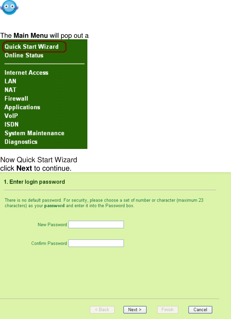
Step2.
The Main Menu will pop out after completing previous step.
Step3.
Now Quick Start Wizard is switched on. Enter login password. Then
click Next to continue.
Step 4
Select the value of connecting to your subscribed ISP.
Note: If your router is provided by your ISP, you might not be able to
allow change any settings to switch to another ISP. You shall check
your contract clauses requested by your ISP before you would like to
change settings or select new ISP.

Vigor2500V series
1-3
Enter the IP address information originally provided by your ISP if you
obtained fixed IP from your ISP.
Step 5
The router will connect into your ISP “on demand”. Demand is
determined as being when any LAN user tries to send data onto the
Internet. When there is no data traffic, the router will close the
connection to the ISP because there is no demand. “Idle timeout ” is
determined by there being no Internet traffic for a period, for example 10
minutes. You can select 0 (zero) for no timeout-the router stays
connected once the router logs in. You can also select -1 (minus one)
which selects “Always On”—the router will try to keep a permanent
connection. The 0 and -1 settings are only recommended for AO
(always on) connections such as ADSL. You can also simply click
“Always On”.

Vigor2500V series
1-4
Because we also have the Quick Start Wizard on the router CD, you will not need
to get Quick Start Wizard from the CD after you already followed the previous
procedure and get on the Internet access.
If you do not want to follow previous procedure, you still can use Quick Start
Wizard from the router CD. You shall firstly get into the router tool and install the
Quick Start Wizard:

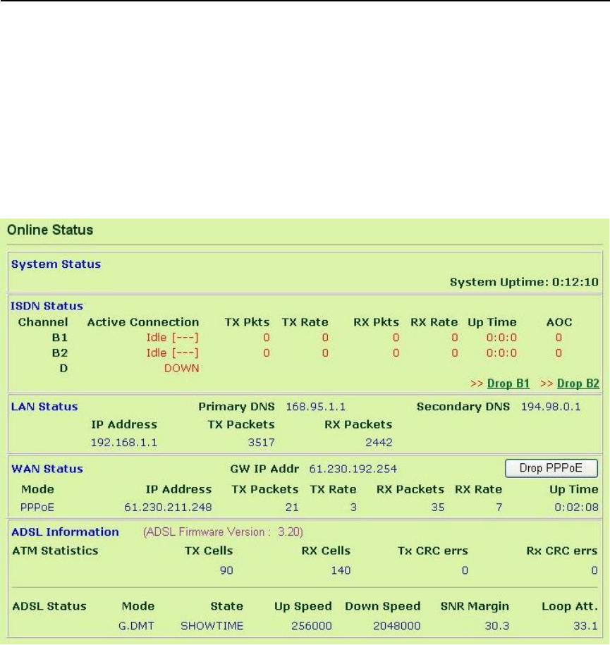
Online Status
2-2
One may find that the Online Status page contains three basic subgroups.
That is, System Status, LAN Status, WAN Status, and ADSL Information.
However, for the ISDN model, the Online Status page also displays the
status of ISDN connection.
2.2.1 System Status
System Uptime: This represents the router’s running time. The format
is HH:MM:SS, where HH, MM, and SS, indicate hours, minutes, and
seconds, respectively.
2.2.2 LAN Status
IP Address: IP address of the LAN interface.
TX Packets: Total number of transmitted IP packets since the router
was powered on.
RX Packets: Total number of received IP packets since the router was
powered on.
2.2.3 WAN Status
Mode: Indicate which ADSL access mode is active. Depending upon
the ADSL access mode, you may see PPPoE, PPPoA, or MPoA.
GW IP Addr: The gateway IP address.
IP Address: IP address of the WAN interface.
TX Packets: Total number of transmitted IP packets during this
connection session.
TX Rate: Transmission rate in characters per second (cps) for

Online Status
2-4
2.2.5 ADSL Information
The router’s online status screen (as well as the telnet logs) show you
two figures which relate to the level and quality of ADSL line signal.
A good ADSL signal is more reliable and generates less errors.
When you order your ADSL line, your telephon company or ISP will
assure your ADSL connection is working.
ADSL Firmware Version: Indicates the ADSL modem chipset
firmware (it is different from router firmware).
ATM Statistics:
TX Blocks: Total number of transmitted ATM Blocks.
RX Blocks: Total number of received ATM Blocks.
Corrected Blocks: Total number of received ATM Blocks which is
corrupted but corrected.
Uncorrected Blocks: Total number of received ATM Blocks which is
corrupted but uncorrected
ADSL Status:
Mode: Indicate which modulation mode is used: G.DMT, G.Lite, or
T1.413.
State: Indicate the DSL line status.
Up Speed: Indicate Up Stream Speed (bits/ second).
Down Speed: Indicate Down Stream Speed (bits/ second).
SNR Margin: Indicate Signal Noise Ratio Margin (dB). The higher
value has better signal quality.
Loop Att. : Indicate subscribed Loop Attenuation.

Vigor2500V series
3-1
Chapter 3
Internet Access
3.1 Introduction
For most users, Internet access is the primary application. The Vigor2500V
series supports the ADSL WAN interface for Internet access and remote
access. The following sections will explain more detailed ADSL access setup.
When you click Internet Access Setup, you can configure the router to
access the Internet with different modes (e.g. PPPoE, PPPoA and MPoA)
The following is the setting path for this function.
Internet Access Setup > PPPoE / PPPoA
> MPoA (RFC 1483 / 2684)
> Multi-PVCs
For ADSL access users, you need to know what kind of internet access is
provided by your ISP. The PPPoE / PPPoA and MPoA (RFC 1483 / 2684) are
mutually exclusive.
Note:
We recommend you to consult with your dealer or ISP before you
would like to run Multi-PVC. In most cases, you do not need to activate
any settings on the menu of multi-PVC because our MultiPVC is
currently with framework for ISP or Telco to integrate its detailed
infrastructure.

Internet Access
3-2
3.2 Configuration
3.2.1 For PPPoE/PPPoA Users
Enter your allocated username, password and DSL parameters according to
the information provided by your ISP. If you want to connect to Internet all the
time, you can check ‘Always On’.
PPPoE Pass-through
The Vigor router offers PPPoE dial-up connection. Besides, you also can
establish the PPPoE connection directly from local clients to your ISP via the
Vigor router.
For Wired LAN
Check this checkbox. The PPPoE connection from
local clients to the ISP goes straight through wired LAN.
Internet Access
3-3
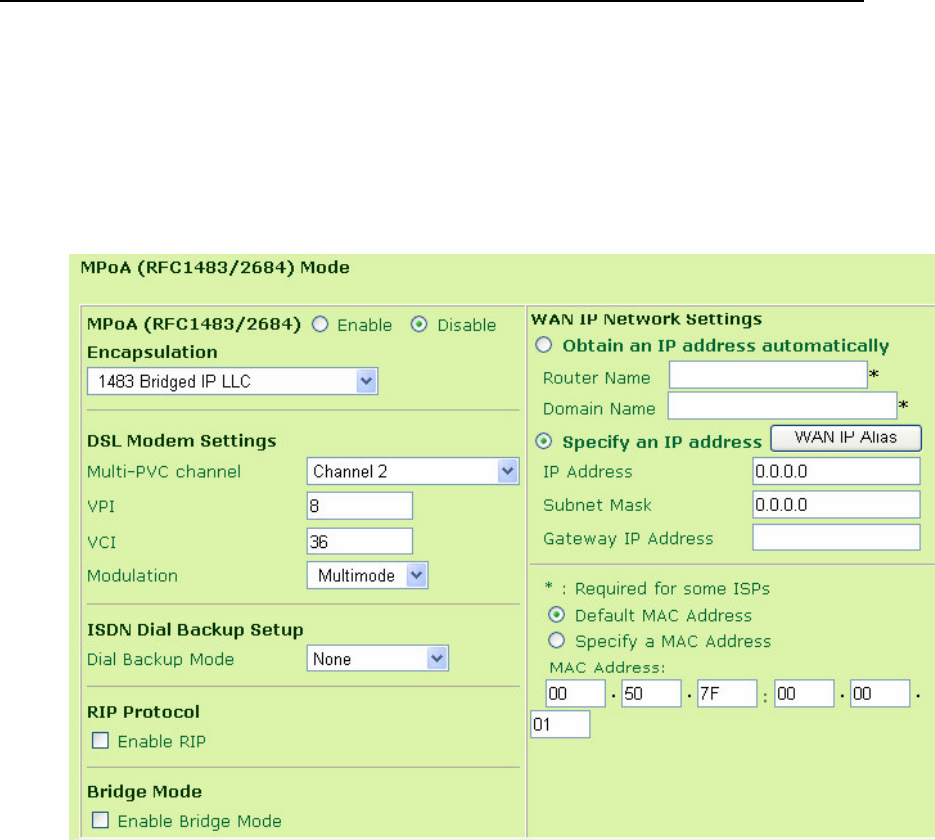
3.2.2 For MPoA (RFC 1483/2684) Users
Enter your allocated WAN IP address (or enabling DHCP client to get IP from
ISP) and DSL parameters according to the information provided by your ISP.
RIP Protocol
Routing Information Protocol is abbreviated as RIPRFC1058specifying
how routers exchange routing tables information.
Enable RIP
Check this checkbox. The router periodically exchanges
entire routing tables.
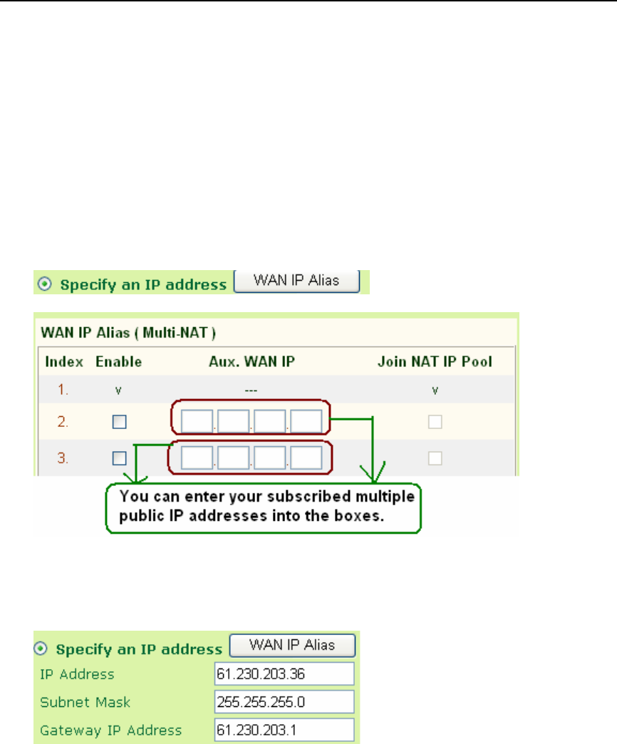
If you have multiple public IPs, they are assigned from the WAN interface.
Click WAN IP Alias, the following windows will be pop-up. You can assign
additional IPs on the page, and click OK.

Internet Access
3-4

Internet Access
3-5
3.2.3 Multi-PVCs
The MultiPVCs are related to the services and management policy of ISP or
Telco. In most countries, the MultiPVC is designed for remote
management in order to save the labour of technical support of ISP or
Telco.
Enter your allocated DSL parameters according to the information provided
by your ISP. QoS Type means QoS offered by ATM, default UBR is
recommend.
We recommend you to consult with your dealer or ISP before you would
like to run Multi-PVC. In most cases, you do not need to activate any
settings on the menu of multi-PVC because our MultiPVC is currently
with framework for ISP or Telco to integrate its detailed infrastructure.
Internet Access
3-6
Detect ATM/ DSL Setting from Quick Start Wizard
You can also be guided by
Quick Start Wizard
to detect ATM/ DSL setting.
Please follow the instructions to operate. If your country is not on the list, it
may take longer time to detect.
Internet Statistics
You can know the DSL status via status monitor.

Vigor2500V series
4-1
Chapter 4
LAN TCP/IP and DHCP
4.1
LAN IP Network Configuration
In the Vigor router, there are two sets of IP address settings for the LAN
interface, as shown below. The 1st IP address/subnet mask is for private
users or NAT users, and the 2nd IP address/subnet mask is for public users.
To allow public users, you need to have subscribed to a globally reachable
subnet from your ISP.
For example, for some DSL accounts, the ISP will assign a few public IP
addresses for your local network. You could use one IP address for your
router, and the 2nd IP address/subnet mask should be configured with the
public IP address. Other local PCs should set the router IP address as the
default gateway. When the DSL connection to the ISP has been established,
each local PC will directly route to the Internet. Also, you could use the 1st IP
address/subnet mask to connect to other private users (PCs). These IP
addresses of the users will be translated to the 2nd IP address by the router
and sent out via the DSL connection.
The following is the setting path for this function.
Internet Access Setup > LAN TCP/IP and DHCP

LAN TCP/IP and DHCP
4-4
routers connected to LAN interface.
2nd Subnet: Set the 2nd subnet to exchange RIP packets with neighbor
routers connected to LAN interface.
4.2
DHCP Server Configuration
DHCP stands for Dynamic Host Configuration Protocol. It can automatically
dispatch related IP settings to any local user configured as a DHCP client.
Please refer to the following picture for DHCP Server Configuration.
Enable Server: Assign IP address to LAN PC automatically.
Disable Server: Assign IP address to LAN PC manually.
Relay Agent: Allows PCs on LAN to request IP address from other DHCP
server.
Start IP Address: Set the start IP address of the IP address pool.
IP Pool Counts: Set the number of IP address pool.
Gateway IP Address: Sets the gateway IP address for the DHCP server.
Usually, it should be same as 1st IP address when the router works as a
default gateway.

LAN TCP/IP and DHCP
4-5
4.3
How you operate DNS on the Vigor router?
The Internet traffic travels between two points addresses by their numeric IP
address. To make the Internet friendly, we are more accustomed to using
names rather than numbers (e.g. www.draytek.com) but those names often
need to be converted back into their real numeric address for the data to be
sent; this is known as “name resolution”. A DNS server proceed this
conversion for us so all users on the LAN need to know about a DNS server
in order to resolve addresses.
Your PC will be told of the DNS server to use if your PC is getting its own IP
address automatically from the router (using DHCP). The router will pre-set
DNS servers initially, but the ISP will allocate their own DNS servers which
are then used once the router has connected to the ISP. As a result, you
can over-ride all DNS server settings and force your own by entering them
into the DNS fields on the LAN setup menu
Primary IP Address: Sets the IP address of the primary DNS server.
Secondary IP Address: Sets the IP address of the secondary DNS server.
Your ISP allocates its own DNS servers when the router logs into the ISP.
These DNS servers will then over-ride the manual settings. If you still want
to force the manual settings to apply, you can use telnet command “ srv
dhcp frcdnsmanl on” (use “off” to disable it. Requires firmware version
2.5.6 or later)

LAN TCP/IP and DHCP
4-6
If both the Primary IP and Secondary IP Address fields are left empty, the
router will assign its own IP address to local users as a DNS proxy server
and maintain a DNS cache. If the IP address of a domain name is already
in the DNS cache, the router will resolve the domain name immediately.
Otherwise, the router forwards the DNS query packet to the external DNS
server by establishing a WAN (e.g. DSL/Cable) connection.

Vigor2500V series
5-1
Chapter 5
NAT (Network Address Translation)
5.1 Introduction
NAT (Network Address Translation) provides you with a method of mapping
one or more IP addresses and/or service ports into different specified
applications. The Vigor router takes a single public IP address, allocated by
your ISP and automatically forwards data between the Vigor router and the
local computer or laptop on your local network. For the outside world, the
public IP address of the router is visible by external users. However, the
external users cannot address the internal private IP address of every
computer / laptop. Any “unsolicited” TCP/IP packet to your public IP
address will arrive at your router but the router can not send the packet to any
computer or laptop on the LAN. The NAT plays an important guard for your
network clients because the internal private IP address of every computer or
laptop is hidden from the outside world, unless you open up ports/protocols to
allow contact.
Through a single public IP address, several computers of your internal local
network can share the broadband access of an ADSL line. For cost concern,
you do not need to subscribe more than one public IP address for every
computer or laptop because the NAT facility of Vigor router can transform a
single public IP address to many internal private IP addresses.

NAT
5-2
5.2 NAT Setup
In the most common type of router installation, you use the NAT facility of the
router. The NAT-enabled router gets one (in Single ISP, PPPoE, PPPoA,
MPoA) globally re-routable IP addresses from the ISP and assigns private
network IP addresses defined by RFC-1918 to local hosts. The NAT-enable
router translates the private network addresses to such a globally routable IP
address so that local hosts can communicate with the router and access the
Internet. The Vigor router let you have three types of port mapping as follows:
Port Redirection
DMZ Host
Open Ports
In terms of the definition of RFC1918 for the private IP addresses, the users
apply the 192.168.1.0/24 to local network clients. e.g. you have three
computers located at different room and you assign three private addresses
to these three computers. You can access Internet from these three
computers because Vigor router can transform these three private IP
addresses to a single public IP address which you subscribed from your ISP.
The following is the setting path for this function.
NAT > Port Redirection
> DMZ Host
> Open Ports
> Well-Known Ports List

NAT
5-3
5.3 Configure Port Redirection Table
The Port Redirection is for you to expose internal servers to the public
domain. For example, you run a web server and some users want to access
this web server. You also run an internal SMTP mail server for your home
office and you shall allow your ISP to send whole E-mail to your SMTP mail
server. Consequently, you assign different port number on the Port
Redirection Table to different services such as http, smtp, ftp etc. External
users, i.e. people elsewhere on the Internet can then access your web server
via your public IP address. Even if your public IP address is a dynamic IP
address, you can apply the Dynamic DNS service to obtain an online WAN IP
address (such as hostnmae.dyndns.org) where is able to be mapped to your
current dynamic IP address. Any external user can visit your web server
simply via your online WAN IP address.
The following example shows how an internal FTP server is exposed to the
public domain. The internal FTP server is running on the local host addressed
as 192.168.1.10.

NAT
5-4
As shown above, the Port Redirection Table provides10 port-mapping
entries for internal hosts.
Service Name: Specify the name for the specific network service.
Protocol: Specify the transport layer protocol (TCP or UDP).
Public Port: Specify which port should be redirected to the internal host.
Private IP: Specify the private IP address of the internal host offering the
service.
Private Port: Specify the private port number of the service offered by
the internal host.
Active: Check here to activate the port-mapping entry.
Click OK
Because the router has its own built-in web server for the configuration, if
you want to access to the web configurator remotely and to a web server
behind the router, you need to change the router’s http “port” to something
other than the default port 80. You shall change the admin port from the
Management Setup menu and you then access the admin screen by
suffixing the normal IP address of Vigor router’s web configurator with 8080.
e.g. http://192.168.1.1:8080

NAT
5-5
The port redirection can only be applied to external users only - i.e. the
incoming traffic. The Internet users behind your LAN can not access your
external public IP address and come back in; the internal users shall
access the server on its local private IP address, or you can set up an alias
in a Windows hosts file. Please only redirect the ports you know you have
to forward rather than forward all ports. Otherwise, you will compromise the
firewall-type security initially deployed by the NAT facility.
5.4 DMZ Host Setup
The Port Redirection can direct UDP/TCP traffic on particular ports to
specified internal clients on the LAN. However, other IP protocols, for
example Protocols 50 (ESP) and 51 (AH) do not have port numbers so you
can not decide which local client to forward the data to. Vigor router has a
facility called DMZ which you can specify a single local client (with private IP
address) to which ALL unsolicited data on all protocols shall be forwarded.
Regular web surfing and other such Internet activities from other clients will
continue to work without inappropriate interruption.
The inherent security properties of NAT are somewhat bypassed if you set
up DMZ. You can consider adding additional filter rules or a secondary
firewall.
There are some non-NAT-friendly protocols although a DMZ will pass all data.
The “AH” extension to IPSec is designed in such principle. It prevents
NAT – the header encodes the source IP address, which in this case would
be your private IP address. The receiving end will see the packet as having
come from your public IP address and thus reject the packet. AH protocol
therefore will not work. ESP is more tolerant.

NAT
5-6
Click DMZ Host Setup to open the setup page, as shown below. The DMZ
Host setting allows a defined internal user to be exposed to the Internet in
order to use some special-IP-Protocol applications such as Netmeeting or
Internet Games etc. Each item in the setup page is described below.
Enable: Check to enable the DMZ Host function.
Private IP: Enter the private IP address of the DMZ host.
Choose PC: Click this button and then a window consisting of a list of
private IP addresses of all hosts in your LAN network will
automatically pop up. Select one private IP address in the
list to be the DMZ host.

NAT
5-7
5.5 Open Port Setup
As Port Redirection (above) but allows you to define a range of ports.
The following screen shows the Open Ports Setup. In the Vigor router, the
Open Ports facility provides 10 entries for internal hosts.
Index: Indicate the relative number for the particular entry that you want
to offer service in a local host. You should click the appropriate
index number to edit or clear the corresponding entry.
Comment: Display the name for the specified network service.
Local IP Address: Display the private IP address of the local host
offering the service.
Status: Display the state for the corresponding entry. We use X or V to
represent the Inactive or Active state.
NAT
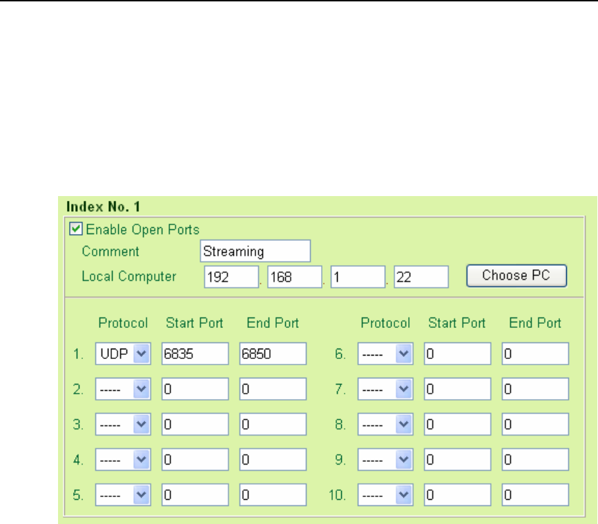
5-8
As stated above, after you click one index number, say index No. 1, in the
above figure, you will see the following setup page for the entry with index No.
1. Further, each entry (local host) can specify 10 port-ranges for varied
services. The computer with private IP address of 192.168.1.22 will be the
host for the specified incoming packet of named as “streaming”. Following
example, the UDP port ranges from 6835 to 6850.
Enable Open Ports: Check to enable the Open Port function for this entry.
Comment: Specify the name for the defined network service.
Local Computer: Enter the private IP address of the local host.
Choose PC: Click this button and, subsequently, a window having a list of
private IP addresses of local hosts will automatically pop up.
Select one appropriate IP address of the local host in the list.
Protocol: Specify the transport layer protocol. It could be TCP, UDP, or
NONE for selection.

NAT
5-9
Start Port: Specify the starting port number of the service offered by the local
host.
End Port: Specify the ending port number of the service offered by the local
host.
5.6 The Precedence of three variants of port mapping
The Vigor router supports three variants of port mapping methods: Port
Redirection, Open Ports and DMZ.
Port Redirection –The incoming packet is redirected to a specific local
computer or laptop if the port number matches that defined. You can
forward the port to another port locally.
Open Ports -- As Port Redirection (above) but allows you to define a
range of ports.
DMZ Host – This opens up a single computer or laptop completely.
All incoming packets will be forwarded onto the PC with the local IP
address you specified. The only exceptions are packets received in
response to outgoing requests form other local PCs or incoming
packets which match rules in the other two methods.
While you are using combinations of these three systems, there is a priority
structure. The precedence of these three types of port mapping is
defined as follows:
Port Redirection > Open Ports > DMZ
For example: The packet will be forwarded to the local address defined in
Port Redirection if the port number of an incoming packet matches a rule
specified in both Port
Redirection and Open Ports.

NAT
5-10
5.7 Well-known Port Number List
This page provides some well-known port numbers for your reference.
5.8 Multi-NAT Setup
The NAT, Network Address Translation establishes a many-to-one
relationship from your private IP address to your single public IP address. In
the most common type of router usage, the user uses the NAT facility of the
router to utilize the broadband access. i.e. Your family members can have
their own computer or laptop for Internet access but you just subscribe one
public IP address. Every computer or laptop receives a private IP address
from Vigor router. The NAT provides essential security to your network
clients because their private address is hidden from the outside world and
can not be reached directly, unless they are authorized to be contacted by
opening up ports/protocols.
NAT
5-11
The MultiNAT can be deployed where your ISP offers you multiple public IP
addresses by your ISP. As a result, you can have a one-to-one relationship
between a public address and a private IP address. This means that you
still have the security from NAT but the computer or laptop can be addressed
directly from the outside world by its associated public IP address, but still by
only opening specific ports to it (e.g. TCP port 80 for an http/web server).
To achieve it, you should find the path to click the button of WAN IP Alias
which is located inside Internet Access Setup.
You follow the path Internet Access>>MPoA if your ISP offer you with MPoA:

NAT
5-12
You follow the path Internet Access>>PPPoE/PPPoA if your ISP offer you
with PPPoE or PPPoA:
When you click the WAN IP Alias button, it will show up a window for you to
set your public IP addresses, as shown below. After set the public
addresses in the appropriate boxes, you shall check Join NAT IP Pool to let
your network client to use these public IP addresses to communicate outside
world. i.e. you can specify one computer to be your web server for showing
your personal data when you would like to make friends. Furthermore, you
can assign another public IP addresses for your kids to participate in the
distance learning over Internet.
After you enter some of your public IP addresses into the WAN IP Alias
(Multi-NAT) menu, these addresses will then be selectable on either the
NAT/Open ports menu or the NAT/DMZ menu.

NAT
5-13
After the public IP addresses are kept within NAT IP pool, these public IP
addresses are selectable on NAT/Open Ports menu. For example, you can
specify one computer for XBox Live by open UDP port and TCP port:
The Vigor2500V series shall be compatible with XBox Live. If it does not work in
the default configuration, you can open UDP Ports 88 and 3074 and TCP Port
3074 to redirect the Xbox’s local IP address.
You select one public IP (e.g. 61.230.203.39) to the specified computer on the
LAN. The specified computer is with private IP address 192.168.1.20. XBox Live
will not be prevented from Vigor router after you open UDP Ports 88 and 3074,
and TCP Port 3074.

NAT
5-14
After the public IP addresses are kept within NAT IP pool, these public IP
addresses are selectable on NAT/DMZ Ports menu. You can specify computer
on the LAN to be with public IP address and let all incoming packets be forwarded
onto the PC with local IP address you set. For example, you let your PC with
private IP 192.168.1.17 be able to play Netmeeting. This computer is also
assigned with public IP address 61.230.203.39. The Netmeeting will not be
blocked by the inherent security function of NAT.
The inherent security properties of NAT are somewhat bypassed if you set
up DMZ. You can consider adding additional filter rules or a secondary
firewall.
The Vigor2500V series ADSL router is already equipped with the ALG’s
(Application Level Gateways) in order to increase the interoperability with
multimedia applications for the limitation of NAT. DrayTek ALG’s is
already integrated with the router firmware so that you do not need to set
any settings onto Vigor router.

Vigor2500V series
6-1
Chapter 6
Firewall
6.1 Introduction
Security is top priority to be took into consideration as the users of
ADSL broadband demands more bandwidth for multimedia,
interactive applications, or distance learning. The Firewall function
helps protect your local network against attack from unauthorized
outsiders. It also provides a way of restricting users on the local
network from accessing the Internet. Additionally, it can filter out
specific packets to trigger the router to place an outgoing connection.
The users on the LAN are provided with secured protection by means
of following firewall facilities:
Stateful Packet Inspection: tracks packets and denies unsolicited
incoming data
Selectable DoS/DDoS protection
User-configurable packet filter
NAT/PAT with Port Forwarding/Redirection & DMZ
Supports ALGs (Application Layer Gateways)
Virtual server via port redirection or open ports feature
E-mail alerting mechanism
Note: When you would like to activate SPI (Stateful Packet
Inspection), please follow the path: Firewall>Edit Filter Rule.:

Firewall
6-2
6.2 An Overview of the Firewall
The Firewall Setup in the Vigor router mainly consists of the packet
filtering, DoS (Denial of Service) defense, and URL (Universal
Resource Locator) content filtering facilities. In this chapter, we focus
on the introduction of the packet filtering function. In the Supplement
A and B chapters, we will explain more about DoS defense and URL
content filtering facilities.
The packet filtering function contains, by default, two types of filter
sets: Call Filter set and Data Filter set. The Call Filter is used for users
that attempt to establish a connection from LAN side to the Internet.
The Data Filter set is used to determine what kind of IP packets is
allowed to pass through the router when the WAN connection has
been established.
Conceptually, when an outgoing packet is to be routed to the WAN,
the IP Filter will decide if the packet should be forwarded to the Call
Filter or Data Filter. If the WAN link is down, the packet will enter the
Call Filter. If the packet is not allowed to trigger router dialing, it will be
dropped. Otherwise, it will initiate a call to establish the WAN
connection.
If the WAN link of the router is up, the packet will pass through the
Data Filter. If the packet type is set to be blocked, it will be dropped.
Otherwise, it will be sent to the WAN interface. Alternatively, if an
incoming packet enters from the WAN interface, it will pass through
the Data Filter directly. If the packet type is set to be blocked, it will be
dropped. Otherwise, it will be sent to the internal LAN. The filter
architecture is shown below.

Firewall
6-4
URL Content Filter: Here provides the capability of blocking
inappropriate web-sites to protect child in school or at home. The more
details can be found in the Supplement B of Chapter 6.
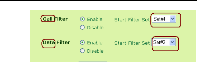
6.3 General Setup
In the General Setup page you can enable/disable the Call Filter or
Data Filter and assign a Start Filter Set for each, configure the log
settings, and set a MAC address for the logged packets to be
duplicated to.
Call Filter: Check Enable to activate the Call Filter function.
Assign a start filter set for the Call Filter.
Data Filter: Check Enable to activate the Data Filter function.
Assign a start filter set for the Data Filter.

Firewall
6-5
Log Flag: For troubleshooting needs you can specify the filter
log here.
None: The log function is inactive.
Block: All blocked packets will be logged.
Pass: All passed packets will be logged.
No Match: The log function will record all packets which are
not matched.
The filter log will be displayed on the Telnet terminal when you type the
“log -f” command.
MAC Address for Packet Duplication: Logged packets may also
be logged to another location via Ethernet. If you want to
duplicate logged packets from the router to another network device,
you must enter the other devices’ MAC Address (HEX Format).
Type “0” to disable the feature. The feature will be helpful under
Ethernet environments.
6.4 Editing the Filter Sets
Comments: Enter filter set comments/description. Maximum
length is 23 characters.
Filter Rule: Click a button numbered 1 ~ 7 to edit the filter rule.
Active: Enable or disable the filter rule.
Next Filter Set: Specifies the next filter set to be linked behind the
current filter set. The filters cannot be looped.
The following setup pages show the default settings for the Call
Filter and the Data Filter. You will see the Call Filter set is assigned
to Set 1 and the Data Filter set to Set 2.
Firewall
6-6
6.5 Editing the Filter Rules
Click the Filter Rule index button to enter the Filter Rule setup
page for each filter. The following explains each configurable item
in detail.
Comments: Enter filter set comments/description. Maximum
length is 14 characters.
Check to enable the Filter Rule: Enables the filter rule.
Pass or Block: Specifies the action to be taken when packets
match the rule.
Block Immediately: Packets matching the rule will be
dropped immediately.
Pass Immediately: Packets matching the rule will be passed
immediately.
Block If No Further Match: A packet matching the rule, and
that does not match further rules, will be dropped.
Pass If No Further Match: A packet matching the rule, and
that does not match further rules, will be passed through.

Firewall
6-8
Address will prevent this rule from being applied to that IP
address. It is equal to the logical NOT operator.
Subnet Mask: Specifies the Subnet Mask for the IP Address
column for this filter rule to apply to.
Operator: The operator column specifies the port number settings.
If the Start Port is empty, the Start Port and the End Port
column will be ignored. The filter rule will filter out any port
number.
= : If the End Port is empty, the filter rule will set the port
number to be the value of the Start Port. Otherwise, the port
number ranges between the Start Port and the End Port
(including the Start Port and the End Port).
!= : If the End Port is empty, the port number is not equal to
the value of the Start Port. Otherwise, this port number is not
between the Start Port and the End Port (including the Start
Port and End Port).
> : Specifies the port number is larger than the Start Port
(includes the Start Port).
< : Specifies the port number is less than the Start Port
(includes the Start Port).
Keep State (Stateful Packet Inspection): When checked,
protocol information about the TCP/UDP/ICMP communication
sessions will be kept by the IP Filter/Firewall (the Firewall Protocol
option (see page 5-21) requires that TCP or UDP or TCP/UDP or
ICMP be selected for this to operate correctly).

Firewall
6-12
300 packets per second and 10 seconds, respectively. A brief description
for each item in the DoS defense function is shown below.
Enable DoS Defense: Click the checkbox to activate the DoS
Defense Functionality.
Enable SYN flood defense: Click the checkbox to activate the SYN
flood defense function. If the amount of the TCP SYN packets
from the Internet exceeds the user-defined threshold value, the
Vigor router will be forced to discard randomly the sequent TCP
SYN packets in the user-defined timeout period. The main goal is
to protect the Vigor router against the TCP SYN packets that
intend to use up the router's limited-resource. By default, the
threshold and timeout values are set to 300 packets per second
and 10 seconds, respectively.
Enable UDP flood defense: Click the checkbox to activate the UDP
flood defense function. Once the UDP packets from the Internet
exceed the user-defined threshold value, the router will be forced
to discard all sequent UDP packets in the user-defined timeout
period. The default setting for threshold and timeout are 300
packets per second and 10 seconds, respectively.
Enable ICMP flood defense: Click the checkbox to activate the ICMP
flood defense function. Similar to the UDP flood defense function,
the router will discard the ICMP echo requests coming from the
Internet, once they exceed the user-defined threshold (by default,
300 packets per second) in a period of time (by default, 10
second for timeout).
Enable Port Scan detection: Port scan attacks occur by sending
packets with different port numbers in an attempt to scanning the
available services that one port will respond. To examine such an
exploration behavior, please click the checkbox to activate the
Port Scan detection function in your Vigor router. The Vigor

Firewall
6-15
A.4 Warning Message
All the warning messages will be sent to syslog client after you enable
the syslog function. The administrator can go to System
Maintenance >> Syslog Setup / Mail Alert to setup the syslog client.
Thus, the administrator can look at the warning messages from DoS
Defense functionality through the DrayTek Sylsog daemon. The format
for this kind of the warning messages is similar to those in Firewall
except for the preamble keyword “DoS”, followed by a name to
indicate what kind of attacks is detected.

Firewall
6-16

Firewall
6-17
Supplement B
URL Content Filtering
B.1 Introduction
The Internet contains a wide range of materials, some of which may be
offensive or even illegal in many countries. Unlike traditional media,
the Internet does not have any obvious tools to segregate materials
based on URL strings or content. URL content filtering systems are
seen as tools that would provide the cyberspace equivalent of the
physical separations that are used to limit access to some particular
materials. In rating a site as objectionable, and refusing to display it on
the user's computer screen, URL content filtering facilities can be used
to prevent children from seeing material that their parents find
objectionable. In preventing access, the URL content filtering facility
acts as an automated version of the convenience-store clerk who
refuses to sell adult magazines to high-school students. The URL
content filtering facilities are also used by businesses to prevent
employees from accessing Internet resources that are either not work
related or otherwise deemed inappropriate.
The name of the URL content filtering comes from checking the content
of the URL strings. Traditional firewall inspects packets based on the
fields of TCP/IP headers, while the URL content filtering checks the URL
strings or the payload of TCP/IP packets. In the Vigor routers, the URL
content filtering facility inspects the URL string and some of HTTP data
hiding in the payload of TCP packets.

Firewall
6-21
into the frames. Thus, your Vigor router will automatically deny any
web surfing that its associated URL string contains any one of the
list’s keywords. Considering that the user tries to access
www.backdoor.net/images/sex /p_386.html, the Vigor router will cut
the connection because this website is prohibited. But, the user is
able to access the website
www.backdoor.net/firewall/forum/d_123.html. Further, the URL
content filtering facility also allows you to specify either a complete
URL string (e.g., “www.whitehouse.com” and “www.hotmail.com”) or
a partial URL string (e.g., “yahoo.com”) in the blocking keyword list.
Accordingly, the Vigor router will identify the forbidden URL and
perform the blocking action for these websites by cutting the
associated connections.
Prevent Web Access by IP Address: One checkbox is available to
activate this function that will deny any web surfing activity by
directly using IP address. To enable it, click on the empty box
image and, subsequently, the hook image ( ) will appear.
Enable Excepting Subnets: 4 entries are available for users to
specify some specific IP addresses or subnets so that they can be
free from the URL Access Control. To enable an entry, click on the
empty checkbox, named as “ACT”, in front of the appropriate entry.
The hook image ( ) appears to indicate the entry is active. To
disable an entry, click on the hook image ( ). (2.5.6 later version)
Enable Restrict Web Feature: It will be of great value to provide the
protection mechanism that prohibits the malicious codes from
downloading from web pages. The malicious codes may embed
in some executable objects, such as ActiveX, Java Applet,
compressed files, and executable files, and, if they have been
downloaded from websites, would bring a threat of the user’s
system. For example, an ActiveX object can be downloaded and

Firewall
6-23
Cookie: Click the checkbox to activate the Block Cookie
transmission.
The Vigor router will filter out cookie from any website.
Proxy: One checkbox appears giving the choice to activate this
function to reject any proxy transmission. To enable it, click
on the empty box image and, subsequently, the hook image
( ) will appear.
To control efficiently the limited-bandwidth usage, it will be of
great value to provide the blocking mechanism that filters out
the multimedia files downloading from web pages. To enable it,
click on the empty box image and, subsequently, the hook image
( ) will appear. Accordingly, files with the following extensions
will be blocked by the Vigor router.
.mov .mp3 .rm .ra .au .wmv
.wav .asf .mpg .mpeg .avi .ram
Time Schedule: Specify what time should perform the URL content
filtering facility. (2.5.6 later version)
Always Block: Click it so that the URL content filtering facility can
be executed on the Vigor router anytime.
Block from H1:M1 To H2:M2: Specify the appropriate time
duration from H1:M1 to H2:M2 in one day, where H1 and H2
indicate the hours. M1 and M2 represent the minutes.
Days of Week: Specify which days in one week should apply
the URL content filtering facility. The Vigor router supports
two exclusive options for users, i.e. everyday or some days
in one week. If you expect that the URL content filtering
facility is active for whole week, you should click the
checkbox “Everyday”. Otherwise, you should point clearly
out the days in one week. For example, if you want the
Firewall
6-24
URL content filtering facility to work from Monday to
Wednesday, then you should click the appropriate
checkboxes (Monday, Tuesday, and Wednesday). Other
days the URL content filtering facility will be silent.
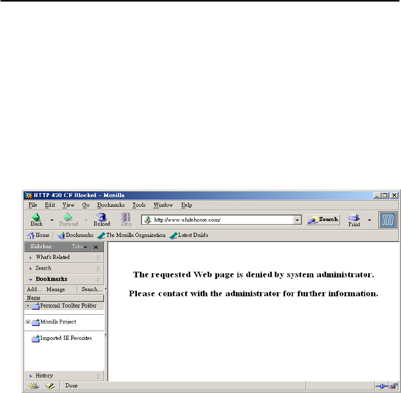
B.4 Warning Message
When a HTTP request is denied, an alert page will appear in your browser,
as shown in the following figure.
Also, the warning message will be automatically sent to the syslog client
after you enable the syslog function. The administrator can setup the
syslog client in the Syslog Setup by using Web Configurator. Thus, the
administrator can view the warning messages from the URL Content
Filtering functionality through the DrayTek Sylsog daemon. The format
for this kind of the warning messages is similar to those in the Firewall
except for the preamble keyword “CF”, followed by a name to indicate
what kind of the HTTP request is blocked.

Dynamic DNS
7-3
Disable the Function and Clear all Dynamic DNS Accounts
1. Go to Applications > Dynamic DNS.
2. Uncheck Enable Dynamic DNS Setup, and click Clear All button to
disable the function and clear all accounts from the router.
Delete a Dynamic DNS Account
1. Go to Applications > Dynamic DNS.
2. Click the Index number you want to delete, and click Clear All button to
delete the account.

Dynamic DNS
7-5
If you encounter any difficulties of using DDNS, you can send the DDNS
log to your local dealer or us support@draytek.com to offer you with
more assistance.
3. Click Online Status to know what the current WAN IP address is
You will see the IP address in the circle, which is the same as the Return
Code in the DDNS logs. This indicates that the DDNS update is done.
Vigor2500V series
8-1
Chapter 8
Call Schedule
8.1 Introduction
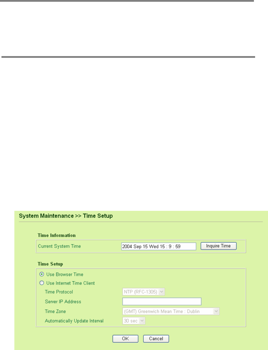
The Vigor router has built a real time clock which can update itself from your
browser manually or automatically from an Internet time server (NTP). As a
result, you can schedule the router to dial to Internet at a pre-set time, but
also to restrict Internet access to certain hours so that the router will only let
users of LAN to access Internet or dial-in access (if there is ISDN interface) at
certain times (e.g. business hours). The call schedule can also be applied
to LAN-to-LAN profiles.
On the Time Setup menu, you can firstly ensure your router time to be
correct before you would like to enforce Call Scheduling.

Call Schedule
8-3
The detailed descriptions for each setting are:
Enable Schedule Setup: Check to enable the schedule.
Start Date (yyyy-mm-dd): Specify the starting date of the schedule.
Start Time (hh:mm): Specify the starting time of the schedule.
Duration Time (hh:mm): Specify the duration (or period) for the
schedule.
Action: Specify which action should be applied by Call Schedule during
the time period of the schedule.
Force On: Specify the connection up.
Force Down: Specify the connection down.
Enable Dial-On-Demand: Specify the connection to be
dial-on-demand and the value of idle timeout should be
specified as following Idle Timeout field.

Call Schedule
8-4
Disable Dial-On-Demand: Specify the connection to be up when it
has traffic on the line. Once there is no traffic over idle timeout,
the connection will be down and never up again during the
schedule.
How Often: Specify how often the schedule will be applied.
Once: The schedule will be applied just once.
Weekdays: Specify which days in one week should perform the
schedule.
Specify appropriate time duration and action to the profile and then click
OK button to apply.
Specify the call schedule to specific Internet access profile or LAN-to-LAN
profile.
Delete a Call Schedule
1. Click Call Schedule Setup and the Index number that you want to
remove.
2. Click Clear button to clear current profile.
8.2 Example of ADSL ISP users
If you want to control the PPPoE Internet access connection to be always-on
(Force On) from 9:00 to 18:00 for whole week. Other time the Internet access
connection should be disconnected (Force Down).
1. Make sure the PPPoE connection and Time Setup is working properly.
2. Configure the PPPoE always-on from 9:00 to 18:00 (the duration is 9
hours) for whole week.
Specyfikacje produktu
| Marka: | Draytek |
| Kategoria: | router |
| Model: | Vigor 2500V |
| Liczba ustawień temperatury: | 2 |
| Wbudowany wyświetlacz: | Nie |
| Długość przewodu: | 1.7 m |
| Położenie urządzenia: | W pełni wbudowany |
| Napięcie wejściowe AC: | 230 V |
| Wysokość produktu: | 598 mm |
| Szerokość produktu: | 598 mm |
| Głębokość produktu: | 550 mm |
| Waga produktu: | 37000 g |
| Kolor drzwiczek: | Nie dotyczy |
| Kolor panelu sterowania: | Czarny |
| Długość węża dopływowego: | 1.4 m |
| Długość węża odpływowego: | 1.7 m |
| Programy mycia: | Eco,Normal,Pre-wash |
| Liczba miejsc: | 12 komplet. |
| Funkcja AquaStop: | Tak |
| Ilość programów piorących: | 3 |
| Poziom hałasu: | 52 dB |
| Opóźniony start czasomierza: | Nie |
| Czas cyklu: | 150 min |
| Obciążenie: | 2300 W |
| Pobór wody na cykl: | 17 l |
| Zużycie energii na cykl: | 1.15 kWh |
| Wskaźnik konieczności płukania: | Tak |
| Wskaźnik soli: | Tak |
| Zabezpieczenie przed dziećmi: | Nie |
| Klasa efektywności energetycznej (stara): | A |
| Programy prania: | Pranie wstępne |
| Roczne zużycie energii: | 327 kWh |
| Kategoria suszenia: | A |
| Roczne spożycie wody: | 4560 l |
Potrzebujesz pomocy?
Jeśli potrzebujesz pomocy z Draytek Vigor 2500V, zadaj pytanie poniżej, a inni użytkownicy Ci odpowiedzą
Instrukcje router Draytek

7 Października 2024
2 Października 2024
2 Października 2024
2 Października 2024
1 Października 2024
1 Października 2024
1 Października 2024
1 Października 2024
1 Października 2024
1 Października 2024
Instrukcje router
- router Samsung
- router Tenda
- router AEG
- router Motorola
- router Xiaomi
- router Huawei
- router TCL
- router TP-Link
- router Milwaukee
- router Gigabyte
- router Acer
- router Bosch
- router Hikvision
- router Roland
- router Nokia
- router Toolcraft
- router Festool
- router EZVIZ
- router Conceptronic
- router StarTech.com
- router Asus
- router Medion
- router Black & Decker
- router TRENDnet
- router MSI
- router D-Link
- router ATen
- router Siemens
- router Thrustmaster
- router DeWalt
- router Einhell
- router Alcatel
- router Sigma
- router HP
- router Teltonika
- router Silverline
- router Manhattan
- router Strong
- router Makita
- router Mikrotik
- router Cisco
- router Moxa
- router Synology
- router Gembird
- router ZTE
- router Lindy
- router Zebra
- router ZyXEL
- router Trust
- router LogiLink
- router Dell
- router IFM
- router Linksys
- router Google
- router Digitus
- router Vimar
- router Dahua Technology
- router Schneider
- router Kyocera
- router Sabrent
- router AVMATRIX
- router Renkforce
- router Netgear
- router Thomson
- router AVM
- router BT
- router Totolink
- router Black Box
- router Güde
- router Apple
- router Lancom
- router Zoom
- router Iogear
- router Intellinet
- router Devolo
- router Vtech
- router Mercusys
- router I-TEC
- router Edimax
- router Razer
- router AirLive
- router EnGenius
- router Planet
- router NEC
- router Blustream
- router LevelOne
- router Digi
- router Milesight
- router Rocstor
- router Hama
- router Ubiquiti Networks
- router Western Digital
- router ModeCom
- router Smart-AVI
- router Barco
- router Sagemcom
- router Juniper
- router Cudy
- router QNAP
- router Arris
- router Netis
- router Anker
- router Allnet
- router Marshall Electronics
- router Hitachi
- router M-life
- router AJA
- router Media-Tech
- router BenQ
- router Atlona
- router FSR
- router Gefen
- router Vivanco
- router Topcom
- router PowerPlus
- router HiKOKI
- router Blackmagic Design
- router Kathrein
- router JUNG
- router Foscam
- router Alfa
- router Porter-Cable
- router Metabo
- router Starlink
- router Keewifi
- router Digital Forecast
- router Keenetic
- router SPL
- router Cotech
- router Skil
- router Alfatron
- router Digitalinx
- router Clas Ohlson
- router KPN
- router Belkin
- router Kramer
- router KanexPro
- router Kopul
- router BZBGear
- router RGBlink
- router Key Digital
- router UPC
- router Lumantek
- router Allied Telesis
- router Actiontec
- router Proximus
- router Eminent
- router Sitecom
- router Sagem
- router Nilox
- router Sonos
- router Patton
- router Techly
- router Envivo
- router Buffalo
- router Nest
- router Vodafone
- router ICIDU
- router Milan
- router Konig
- router AT&T
- router Sweex
- router Aruba
- router Phicomm
- router Kasda
- router Technicolor
- router Verizon
- router Billion
- router T-Mobile
- router RAVPower
- router Hawking Technologies
- router Nexxt
- router WyreStorm
- router Beafon
- router Kraun
- router LTS
- router Zolid
- router Telstra
- router Holzmann
- router SIIG
- router Eero
- router Advantech
- router Mercku
- router Hercules
- router Xantech
- router Intelix
- router MuxLab
- router Pentagram
- router Ocean Matrix
- router Comprehensive
- router Arcadyan
- router Digiconnect
- router Ubee
- router SMC
- router Tele 2
- router Kogan
- router Peak
- router CradlePoint
- router Davolink
- router Sixnet
- router AVPro Edge
- router Evolution
- router 7inova
- router Predator
- router A-NeuVideo
- router United Telecom
- router F-Secure
- router Rosewill
- router Digicom
- router On Networks
- router Wisetiger
- router Leoxsys
- router Readynet
- router OneAccess
- router Accelerated
- router Nexaira
- router Hamlet
- router Approx
- router T-com
- router Amped Wireless
- router Cambium Networks
- router 3Com
- router Avenview
- router Ruckus Wireless
- router Dovado
- router Mach Power
- router EXSYS
- router NetComm
- router Comtrend
- router Premiertek
- router Bea-fon
- router GL.iNet
- router Shinybow
- router Edgewater
- router Atlantis Land
- router Lantronix
- router PulseAudio
- router Luxul
- router DVDO
- router StarIink
- router Silentwind
- router Keezel
- router VigilLink
Najnowsze instrukcje dla router
9 Kwietnia 2025
9 Kwietnia 2025

8 Kwietnia 2025

3 Kwietnia 2025

2 Kwietnia 2025
1 Kwietnia 2025
30 Marca 2025
30 Marca 2025
30 Marca 2025
30 Marca 2025