Instrukcja obsługi Denon ADV-M71
Denon
Zestaw kina domowego
ADV-M71
Przeczytaj poniżej 📖 instrukcję obsługi w języku polskim dla Denon ADV-M71 (228 stron) w kategorii Zestaw kina domowego. Ta instrukcja była pomocna dla 11 osób i została oceniona przez 2 użytkowników na średnio 4.5 gwiazdek
Strona 1/228

B
BAND
PHONES
VOLUME
ON / STANDBY
DVD SURROUND RECEIVER ADV-M71
TONE/SDB
FUNCTION
MENU/SET +
-
SURROUND/SELECT
PUSH
-
PARAM.
+
-
+
-
RC-966
A / V
3
A-B REPEAT
SEARCH MODE
ONOFF
REPEAT RANDOM
CLEAR ZOOMSLIDE MODE
PROG/DIRECT
MEMO BANDMODE
STATUS
RETURN
ANGLE AUDIO
SUB TITLE
SETUP TONE/ SDB
FUNCTIONSURROUNDINPUT MODETEST TONE
DVD
TUNER
CH
3
-
+
21
654
987
0/10
CALL
ENTER
MUTING
+10
DISPLAY MENU
TOP MENU
SYSTEM MD
CDR TAPE
TUNER TV / VCR
SURROUND
PARAMETER
CH SELECT
VCR
NTSC/PAL
SLEEP
ENTER
CD SRS
EDIT/MENUCHARAC.
REC
TIMETITLE
TUNING /
TV VOL
TV CH TV CH
TUNERDVD
MD/LINE-1 TAPE/ LINE-2
AUTO DECODE
VIRTUALDIRECT
5CH STEREO
STEREO
D.AUX
-
+
VCR CH
IN/SURR.
IN/SURR.
DVD
T VTV INSOURCE
+
-
9
8
21
76
RTCT
PTYRDS
DVD SURROUND RECEIVER
ADV-M71
OPERATING INSTRUCTIONS
BEDIENUNGSANLEITUNG
MODE D’EMPLOI
2We greatly appreciate your purchase of this unit.
2To be sure you take maximum advantage of all the features this unit has to offer, read these instructions carefully and use the
set properly. Be sure to keep this manual for future reference should any questions or problems arise.
“SERIAL NO.
PLEASE RECORD UNIT SERIAL NUMBER ATTACHED TO THE REAR OF THE CABINET FOR FUTURE REFERENCE”
FOR ENGLISH READERS PAGE 3 ~ PAGE 115
2Nous vous remercions pour l’achat de cet appareil.
2Pour être sûr de profiter au maximum de toutes les caractéristiques qu’offre cet appareil, lire avec soin ces instructions et bien
utiliser l’appareil. Toujours conserver ce mode d’emploi pour s’y référer ultérieurement en cas de question ou de problème.
“NO. DE SERIE
PRIERE DE NOTER LE NUMERO DE SERIE DE L’APPAREIL INSCRIT A L’ARRIERE DU COFFRET DE FAÇON A POUVOIR LE
CONSULTER EN CAS DE PROBLEME.”
POUR LES LECTEURS FRANCAIS PAGE 228 ~ PAGE 339
2Wir danken Ihnen dafür, dass Sie sich für den Kauf dieses Gerätes entschieden haben.
2Lesen Sie diese Anleitung sorgfältig durch, damit sichergestellt werden kann, dass Sie sämtliche Funktionen ausnutzen, die
dieses Gerät zu bieten hat, und damit Sie das Gerät ordnungsgemäß verwenden. Stellen Sie sicher, dass Sie dieses Handbuch
für ein zukünftiges Nachschlagen aufbewahren, falls Sie irgendwelche Fragen oder Probleme habe sollten.
“SERIAL NO.
PLEASE RECORD UNIT SERIAL NUMBER ATTACHED TO THE REAR OF THE CABINET FOR FUTURE REFERENCE”
FÜR DEUTSCHE LESER SEITE 116 ~ SEITE 227

2
• Avoid high temperatures.
Allow for sufficient heat dispersion when
installed on a rack.
• Vermeiden Sie hohe Temperaturen.
Beachten Sie, daß eine ausreichend
Luftzirkulation gewährleistet wird, wenn das
Gerät auf ein Regal gestellt wird.
• Eviter des températures élevées
Tenir compte d’une dispersion de chaleur
suffisante lors de l’installation sur une
étagère.
• Handle the power cord carefully.
Hold the plug when unplugging the cord.
• Gehen Sie vorsichtig mit dem Netzkabel um.
Halten Sie das Kabel am Stecker, wenn Sie
den Stecker herausziehen.
• Manipuler le cordon d’alimentation avec
précaution.
Tenir la prise lors du débranchement du
cordon.
• Keep the set free from moisture, water, and
dust.
• Halten Sie das Gerät von Feuchtigkeit,
Wasser und Staub fern.
• Protéger l’appareil contre l’humidité, l’eau et
lapoussière.
• Unplug the power cord when not using the
set for long periods of time.
• Wenn das Gerät eine längere Zeit nicht
verwendet werden soll, trennen Sie das
Netzkabel vom Netzstecker.
• Débrancher le cordon d’alimentation lorsque
l’appareil n’est pas utilisé pendant de
longues périodes.
• (For sets with ventilation holes)
Do not obstruct the ventilation holes.
• Die Belüftungsöffnungen dürfen nicht
verdeckt werden.
• Ne pas obstruer les trous d’aération.
• Do not let foreign objects in the set.
• Keine fremden Gegenstände in das Gerät
kommen lassen.
• Ne pas laisser des objets étrangers dans
l’appareil.
• Do not let insecticides, benzene, and thinner
come in contact with the set.
• Lassen Sie das Gerät nicht mit Insektiziden,
Benzin oder Verdünnungsmitteln in
Berührung kommen.
• Ne pas mettre en contact des insecticides,
du benzène et un diluant avec l’appareil.
• Never disassemble or modify the set in any
way.
• Versuchen Sie niemals das Gerät
auseinander zu nehmen oder auf jegliche Art
zu verändern.
• Ne jamais démonter ou modifier l’appareil
d’une manière ou d’une autre.
ENGLISH
CAUTION
RISK OF ELECTRIC SHOCK
DO NOT OPEN
CAUTION:
TO REDUCE THE RISK OF
ELECTRIC SHOCK, DO NOT
REMOVE COVER (OR BACK). NO
USER SERVICEABLE PARTS
INSIDE. REFER SERVICING TO
QUALIFIED SERVICE PERSONNEL.
The lightning flash with arrowhead
symbol, within an equilateral
triangle, is intended to alert the
user to the presence of
uninsulated “dangerous voltage”
within the product’s enclosure
that may be of sufficient
magnitude to constitute a risk of
electric shock to persons.
The exclamation point within an
equilateral triangle is intended to
alert the user to the presence of
important operating and
maintenance (servicing)
instructions in the literature
accompanying the appliance.
WARNING
:TO PREVENT FIRE OR SHOCK
HAZARD, DO NOT EXPOSE THIS
APPLIANCE TO RAIN OR
MOISTURE.
•DECLARATION OF CONFORMITY
We declare under our sole responsibility that this
product, to which this declaration relates, is in
conformity with the following standards:
EN60065, EN55013, EN55020, EN61000-3-2 and
EN61000-3-3.
Following the provisions of 73/23/EEC,
89/336/EEC and 93/68/EEC Directive.
•ÜBEREINSTIMMUNGSERKLÄRUNG
Wir erklären unter unserer Verantwortung, daß
dieses Produkt, auf das sich diese Erklärung
bezieht, den folgenden Standards entspricht:
EN60065, EN55013, EN55020, EN61000-3-2 und
EN61000-3-3.
Entspricht den Verordnungen der Direktive
73/23/EEC, 89/336/EEC und 93/68/EEC.
•DECLARATION DE CONFORMITE
Nous déclarons sous notre seule responsabilité
que l’appareil, auquel se réfère cette déclaration,
est conforme aux standards suivants:
EN60065, EN55013, EN55020, EN61000-3-2 et
EN61000-3-3.
D’après les dispositions de la Directive
73/23/EEC, 89/336/EEC et 93/68/EEC.
DEUTSCH FRANCAIS
ATTENZIONE: QUESTO APPARECCHIO E’ DOTATO DI
DISPOSITIVO OTTICO CON RAGGIO LASER.
L’USO IMPROPRIO DELL’APPARECCHIO PUO’ CAUSARE
PERICOLOSE ESPOSIZIONI A RADIAZIONI!
CLASS 1 LASER PRODUCT
LUOKAN 1 LASERLAITE
KLASS 1 LASERAPPARAT
ADVARSEL:USYNLIG LASERSTRÅLING VED ÅBNING, NÅR
SIKKERHEDSAFBRYDERE ER UDE AF FUNKTION.
UNDGÅ UDSAETTELSE FOR STRÅLING.
VAROITUS!LAITTEEN KÄYTTÄMINEN MUULLA KUIN TÄSSÄ
KÄYTTÖOHJEESSA MAINITULLA TAVALLA SAATTAA
ALTISTAA KÄYTTÄJÄN TURVALLISUUSLUOKAN 1
YLITTÄVÄLLE NÄKYMÄTTÖMÄLLE LASERSÄTEILYLLE.
,
CLASS 1
LASER PRODUCT,
,,
NOTE ON USE / HINWEISE ZUM GEBRAUCH /OBSERVATIONS RELATIVES A L’UTILISATION
CAUTION
• The ventilation should not be impeded by covering the ventilation openings with items,
such as newspapers, table-cloths, curtains, etc.
• No naked flame sources, such as lighted candles, should be placed on the apparatus.
• Please be care the environmental aspects of battery disposal.
• The apparatus shall not be exposed to dripping or splashing for use.
• No objects filled with liquids, such as vases, shall be placed on the apparatus.
VARNING-
OM APPARATEN ANVÄNDS PÅ ANNAT SÄTT ÄN I DENNA
BRUKSANVISNING SPECIFICERATS, KAN ANVÄNDAREN
UTSÄTTAS FÖR OSYNLIG LASERSTRÅLNING SOM
ÖVERSKRIDER GRÄNSEN FÖR LASERKLASS 1.

ENGLISH
3
2INTRODUCTION
2ACCESSORIES
Thank you for choosing the DENON ADV-M71 DVD Surround Receiver. This remarkable component has been engineered to provide superb surround
sound listening with home theater sources such as DVD, as well as providing outstanding high fidelity reproduction of your favorite music sources.
As this product is provided with an immense array of features, we recommend that before you begin hookup and operation that you review the
contents of this manual before proceeding.
TABLE OF CONTENTS
zBEFORE USING ..........................................................................................4
xCAUTIONS ON INSTALLATION ..................................................................4
cCAUTIONS ON HANDLING ........................................................................4
vFEATURES...................................................................................................5
bDISCS..........................................................................................................6
nCAUTIONS ON HANDLING DISCS.............................................................7
mCONNECTIONS ....................................................................................8~14
,PART NAMES AND FUNCTIONS .......................................................15~19
.REMOTE CONTROL UNIT..................................................................20~28
⁄0 SETTING UP THE SYSTEM ................................................................29~38
⁄1 PLAY BACK.........................................................................................39~44
⁄2 OPERATING THE SURROUND FUNCTIONS......................................44~46
⁄3 DOLBY / DTS SURROUND.................................................................47~49
⁄4 SURROUND PLAYBACK.....................................................................50~62
⁄5 LISTENING TO THE RADIO................................................................63~67
⁄6 ON-SCREEN DISPLAY ..............................................................................68
⁄7 USING THE ON-SCREEN DISPLAY ....................................................69~86
⁄8 USING THE TIMER.............................................................................87~93
⁄9 CHANGING THE DEFAULT SETTINGS (DVD)...................................94~106
¤0 SYSTEM FUNCTIONS ....................................................................107~111
¤1 LAST FUNCTION MEMORY ...................................................................112
¤2 INITIALIZATION OF THE MICROPROCESSOR ......................................112
¤3 TROUBLESHOOTING .....................................................................113, 114
¤4 SPECIFICATIONS ....................................................................................115
Check that the following parts are included in addition to the main unit:
qOperating instructions ........................................1 wService station list ..............................................1 eRemote control unit (RC-966).............................1
rR6P/AA batteries ................................................2 tAM loop antenna ................................................1 yFM indoor antenna .............................................1
erty
2
ADV-M71

ENGLISH
4
1
2
BEFORE USING
CAUTIONS ON INSTALLATION
Pay attention to the following before using this unit:
•Moving the set
To prevent short circuits or damaged wires in the connection cords,
always unplug the power cord and disconnect the connection cords
between all other audio components when moving the set.
•Before turning the power switch on
Check once again that all connections are proper and that there are
not problems with the connection cords. Always set the power
switch to the standby position before connecting and disconnecting
connection cords.
•Store this instructions in a safe place.
After reading, store this instructions along with the warranty in a
safe place.
•Note that the illustrations in this instructions may differ from
the actual set for explanation purposes.
Noise or disturbance of the picture may be generated if this unit or
any other electronic equipment using microprocessors is used near a
tuner or TV.
If this happens, take the following steps:
• Install this unit as far as possible from the tuner or TV.
• Set the antenna wires from the tuner or TV away from this unit’s
power cord and input/output connection cords.
• Noise or disturbance tends to occur particularly when using indoor
antennas or 300 Ω/ohms feeder wires. We recommend using
outdoor antennas and 75 Ω/ohms coaxial cables.
For heat dispersal, leave at least 10 cm/4 inch of space between
the top, back and sides of this unit and the wall or other
components.
DVD SURROUND RECEIVER UNIT
B
10 cm/4 inch or more
10 cm/4 inch or more
Wall
3CAUTIONS ON HANDLING
•Switching the input function when input jacks are not
connected
A clicking noise may be produced if the input function is switched
when nothing is connected to the input jacks. If this happens, either
turn down the MASTER VOLUME control or connect components
to the input jacks.
•Muting of PRE OUT jacks, HEADPHONE jack and SPEAKER
terminals
The PRE OUT jacks, HEADPHONE jacks and SPEAKER terminals
include a muting circuit. Because of this, the output signals are
greatly reduced for several seconds after the power switch is
turned on or input function, surround mode or any other-set-up is
changed. If the volume is turned up during this time, the output will
be very high after the muting circuit stops functioning. Always wait
until the muting circuit turns off before adjusting the volume.
DVD SURROUND RECEIVER UNIT
•Whenever the power switch is in the STANDBY state, the
apparatus is still connected on AC line voltage.
Please be sure to unplug the cord when you leave home for,
say, a vacation.

5
ENGLISH
4FEATURES
The ADV-M71 combines an AV amplifier and DVD player, the core
components of a home theater system, into a single compact,
stylish body. The system takes up little space, and the aluminum
front panel and half mirror of the display make for an elegant
design that blends in nicely with the décor in your room.
1. 2-channel power amplifier with Dolby Virtual Speaker
compatibility
The ADV-M71 is equipped with two 35W (6 Ω/ohms 1kHz, T.H.D.
10%) power amplifiers that make it compatible with new Dolby
Virtual Speaker technology for recreating a 5.1-channel
environment virtually using a 2-channel configuration. (Dolby
Virtual Speaker is an proprietary technology of Dolby Laboratories.)
A high performance digital signal processor enables playback of
Dolby Digital and DTS multi-channel surround signals in the Dolby
Virtual Speaker mode. Surround sound can be achieved with the
Dolby Virtual Speaker mode for CDs and other 2-channel sources
in combination with the Dolby Pro Logic II decoder.
2. 3.1-channel pre-out terminals allowing expansion into a 5.1-
channel surround system
When used in combination with a commercially available
subwoofer with built-in amplifier and power amplifier, the ADV-
M71 can be expanded into a 5.1-channel surround system. The
ADV-M71 not only recreates an accurate sound field for multi-
channel sources, it is also compatible with wide mode playback in
the Dolby Virtual Speaker mode.
3. Dolby Pro Logic II decoder for expanding sound field playback
The ADV-M71 is equipped with a Dolby Pro Logic II decoder for
expanding sound field playback for Dolby Surround and stereo
music sources.
4. DENON’s unique sound field simulation using the DSP
The ADV-M71 is compatible with the Rock Arena, Jazz Club and
Video Game modes with a 2-channel configuration. In a 5.1-
channel configuration, it is also compatible with the 5-Channel
Stereo, Mono Movie and Matrix modes.
5. High performance DVD drive for progressive image output
compatibility
The ADV-M71 is compatible with various functions offered by DVD
sources, including multiple audio (up to 8 languages), multiple
subtitle (up to 32 languages), multiple angle playback, viewing
restriction, etc.
6. Quick setup and on-screen display compatibility
DVDs can be enjoyed simply by selecting the TV and speaker
configuration to be used. Even with a 5.1-channel speaker
configuration, standard parameters can be set automatically simply
by selecting the size of the room in which the system is being
used and the listening position. The system can be set up using an
on-screen display function.
7. Remote control unit with preset memory function
The ADV-M71 comes with a remote control unit equipped with a
preset memory function including the remote control operation
codes for D-M31 series MD recorders, cassette decks and
DENON remote control compatible components as well as the
remote control operation codes of other major brands of TVs and
video decks.
8. Convenient system functions
When system connections are made with a D-M31 series MD
recorder and cassette deck, such system functions as auto
function selection, synchronized recording and timer
recording/playback can be performed easily.

ENGLISH
6
5DISCS
• The types of discs listed on the table below can be used on the ADV-M71.
The marks are indicated on the disc labels or jackets.
Usable
discs Mark (logo) Recorded
signals Disc size
DVD video
DVD audio
(NOTE 1)
Digital audio +
digital video
(MPEG2)
12 cm
8 cm
12 cm
8 cm
12 cm
12 cm
8 cm
Digital audio +
digital video
(MPEG1)
Digital audio
MP3
WMA
Digital picture
(JPEG)
Digital picture
(JPEG)
Video CD
CD
CD-R
CD-RW
(NOTE 2)
Picture CD
2Disc terminology
•Titles and chapters (DVD-videos)
DVD-videos are divided into several large sections called “titles”
and smaller sections called “chapters”.
Numbers are allotted to these sections. These numbers are
called “title numbers” and “chapter numbers”.
•Playback control (video CDs)
Video CDs including the words “playback control” on the disc or
jacket are equipped with a function for displaying menus on the
TV screen for selecting the desired position, displaying
information, etc., in dialog fashion.
In this manual, playing video CDs using such menus is referred
to “menu playback”.
Video CDs with playback control can be used on the ADV-M71.
NOTE:
• This DVD video player is designed and
manufactured to respond to the Region
Management Information that is recorded on
a DVD disc.
If the Region number described on the DVD
disc does not correspond to the Region
number of this DVD video player, this DVD
video player cannot play this disc.
The Region number for this DVD video player
is 2.
•Tracks (video and music CDs)
Video and music CDs are divided into sections called “tracks”.
Numbers are allotted to these sections. These numbers are
called “track numbers”.
For example:
For example:
Title 1
Chapter 1 Chapter 2 Chapter 3 Chapter 1 Chapter 2
Title 2
Track 1 Track 2 Track 3 Track 4 Track 5
2
Recordable
ReWritable
7
ENGLISH
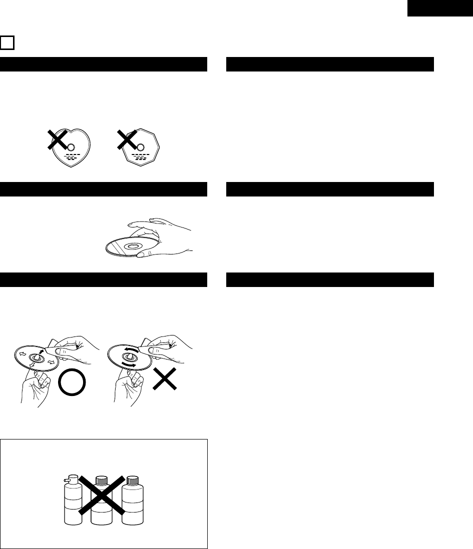
6CAUTIONS ON HANDLING DISCS
Discs
Only the discs including the marks shown on page 6 can be played on
the ADV-M71.
Note, however, that discs with special shapes (heart-shaped discs,
hexagonal discs, etc.) cannot be played on the ADV-M71. Do not
attempt to play such discs, as they may damage the player.
Cautions on Handling Discs
• Do not get fingerprints, grease or dirt on discs.
• Be especially careful not to scratch discs when removing them
from their cases.
• Do not bend discs.
• Do not heat discs.
• Do not enlarge the center hole.
• Do not write on the labeled (printed) side with a ball-point pen or a
pencil.
• Water droplets may form on the surface if the disc is moved
suddenly from a cold place to a warm one. Do not use a hairdryer,
etc., to dry the disc.
Cautions on Storing Discs
• Always eject discs after playing them.
• Keep discs in their cases to protect them from dust, scratches and
warping.
• Do not put discs in the following places:
1. Places exposed to direct sunlight for long periods of time
2. Humid or dusty places
3. Places exposed to heat from heaters, etc.
Cautions on Loading Discs
• Only load one disc at a time. Loading one disc on top of another
may result in damage or scratch the discs.
• Load 8 cm discs securely in the disc guide, without using an
adapter. If the disc is not properly loaded, it may slip out of the
guide and block the disc tray.
• Be careful not to let your fingers get caught when the disc tray is
closing.
• Do not place anything but discs in the disc tray.
• Do not load cracked or warped discs or discs that have been fixed
with adhesive, etc.
• Do not use discs on which the adhesive part of cellophane tape or
glue used to attach the label is exposed, or discs with traces of tape
or labels that have been peeled off. Such discs may get stuck inside
the player, resulting in damage.
Holding Discs
Avoid touching the surface of discs when loading and unloading them.
Cleaning Discs
2Fingerprints or dirt on the disc may lower sound and picture quality
or cause breaks in playback. Wipe off fingerprints or dirt.
2Use a commercially available disc cleaning set or a soft cloth to
wipe off fingerprints or dirt.
Be careful not to get
fingerprints on the signal
surface (the side which
shines in rainbow colors).
Wipe gently from the middle
outwards.
Do not wipe with a circular
motion.
NOTE:
• Do not use record spray or antistatic. Also do not use volatile
chemicals such as benzene or thinner.
Record
spray
Thinner Benzene

ENGLISH
8
RLRLRLRL
R
(L) (R)
7CONNECTIONS
•Do not plug in the AC cord until all connections have been
completed.
•Be sure to connect the left and right channels properly (left with
left, right with right).
•Insert the plugs securely. Incomplete connections will result in
the generation of noise.
•Note that binding pin plug cords together with AC cords or placing
them near a power transformer will result in generating hum or
other noise.
•Noise or humming may be generated if a connected audio
equipment is used independently without turning the power of
this unit on. If this happens, turn on the power of the this unit.
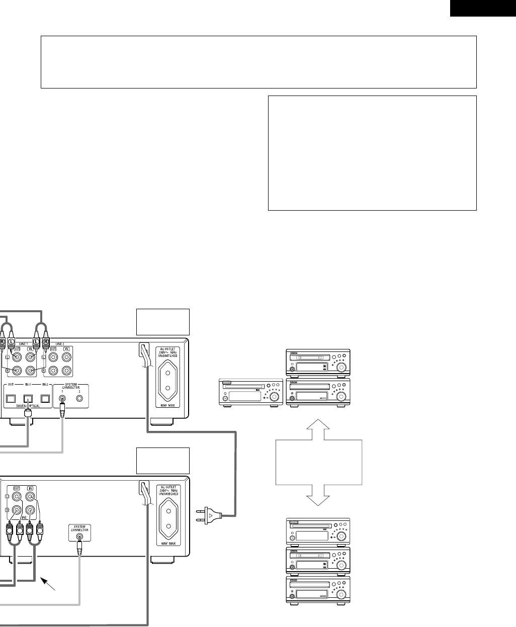
(1) Connecting the audio components (D-M31 series)
•The ADV-M71 can be used connected in a system with the D-M31 series MD recorder (DMD-M31) and cassette deck (DRR-M31).
•For instructions on operating the separately sold MD recorder (DMD-M31) and cassette deck (DRR-M31), refer to their respective operating
instructions.
•Only the DMD-M31 MD recorder and DRR-M31 cassette deck can be connected directly to the ADV-M71 using system connections.
NOTE:
•This system includes digital circuitry which may cause interference such
as color blotching or changes in the color on TVs. If this happens, move
the system and the TV as far apart as possible.
Connecting the speaker systems
Connect the speaker system for the left channel (the left side as seen from the
front) to the L terminals, the speaker system for the right channel to the R
terminals. Refer to the instructions supplied with the speaker system for details.
Be sure to use speaker systems with an impedance of 6 Ω/ohms or greater.
Commercially available subwoofer
with built-in amplifier
ADV-M71 DVD
surround
receiver
Speaker system
SC-M51
Or commercially available
speaker
FM indoor antenna
(included)
AM loop antenna
(included)
AC CORD
AC 230 V, 50 Hz
The ADV-M71 includes a built-in clock function,
so plug its power cord into a wall power outlet to
which electricity is supplied constantly.
Audio cord
Optical transmission
cables System cords
Speaker cords
Stereo audio cord
9
ENGLISH
RLRL
1
18Tr02m 46s
-60 -40 -30 -20 -12 -6 -2 0
L
dB
R
1
18Tr02m 46s
-60 -40 -30 -20 -12 -6 -2 0
L
dB
R
DVD SURROUND RECEIVER ADV-M71
B
BAND
PHONES
VOLUME
ON / STANDBY
TONE/SDB
FUNCTION
MENU/SET
+
-
SURROUND/SELECT
PUSH
-
PARAM.
DVD SURROUND RECEIVER ADV-M71
B
BAND
PHONES
VOLUME
ON / STANDBY
TONE/SDB
FUNCTION
MENU/SET
+
-
SURROUND/SELECT
PUSH
-
PARAM.
CAUTION:
•Only one MD recorder and one cassette deck can be connected to the ADV-M71 using system connections. System operations cannot be
performed properly if two MD recorders or two cassette decks are connected using system connections.
•Whenever the power operation switch is in the STANDBY position, the unit is still connected to AC line voltage.
•Please be sure to unplug the power cord when you leave home for, e.g.,a vacation, etc.
System operations
Such system operations as the timer and the auto power on functions, as well
as remote control operations cannot be performed unless all the RCA pin-plug
cords and system connector cords are connected between the units, so be sure
to make all the connections properly as shown in the diagram. Also,
disconnecting system connectors while the system is operating may result in
malfunctions. Be sure to unplug the power cord before changing connections.
NOTES:
•Do not plug the power cord into the power outlet until all connections are
completed. Be sure to interconnect the channels (L to L (white) and R to
R (red)) properly, as shown on the diagram.
•Use the AC OUTLET for audio equipment only. Do not use them for hair
driers, etc.
•Insert the plugs securely. Incomplete connections may result in noise.
•Be sure to connect the speaker cords between the speaker terminals and
the speaker systems with the same polarities ( + to +, – to – ). If the
polarities are switched, the sound at the center will be weak, the position
of the different instruments will be unclear, and the stereo effect will be
lost.
•After unplugging the power cord, wait about 5 seconds before plugging it
back in.
•Note that setting the connection cords (pin-plug cords) next to the power
cords may result in humming or other noise.
MD recorder
(DMD-M31)
(sold separately)
Cassette deck
(DRR-M31)
(sold separately)
ADV-M71
DRR-M31
DMD-M31
(Horizontal installation)
Install the sets as shown in one
of these diagrams. In either
case, be sure that the DVD
surround receiver’s ventilation
holes are not obstructed.
ADV-M71
DRR-M31
DMD-M31
(Vertical installation)
Stereo audio cord

ENGLISH
10
LR
AUDIO
OUTL
R
LROUT IN L
R
AUDIO
OUT
OPTICAL
B
R
L
L
R
LR
L
RL
R
R
L
(3) Connecting the Audio Signals of a Digital Satellite Tuner and VCR
•Connect the video signals directly to the TV and switch the picture on the TV.
•When making connections, also refer to the operating instructions of the other components.
Connection to the optical digital input terminal
•Only audio signals are input to the optical digital
input terminal.
•Use a commercially available optical transmission
cable for connection to the optical transmission
terminal (OPTICAL).
Connection of a digital satellite/cable tuner
•For tuners equipped with an optical digital output terminal,
connect the digital output terminal to the DIGITAL D.AUX IN
terminal on the ADV-M71 using an optical transmission cable.
•To connect the audio output terminals, use whatever of the
ADV-M71’s LINE-1 or LINE-2 terminals are open.
Connection of a video deck
•Connect the video deck’s audio output and audio input
terminals to whatever of the ADV-M71’s LINE-1 or LINE-2
terminals are open using pin-plug cords.
Video deck
Digital satellite/cable tuner
(2) Connecting the PRE OUT terminals (only with multi-channel settings)
•When used in combination with a commercially available subwoofer with built-in amplifier and power amplifier, the ADV-M71 can be expanded
into a 5.1-channel surround system.
•When making connections, also refer to the operating instructions of the other components.
•To make the 5.1-channel setting, set the speakers to “5.1 CH SURROUND” in the quick system setup and select “Room Setting” and
“Listening Position”. (See pages 31 to 32.)
SUBWOOFER
•Connect the subwoofer with built-in
amplifier.
POWER AMPLIFIER
(for center ch)
POWER AMPLIFIER
(for Surround ch)
•Connect the power
amplifier for center and
surround speaker
system.
Center Speaker
Surround (L) Speaker
Surround (R) Speaker
IN
IN
IN
IN

11
ENGLISH
(4) Connecting a TV
•Use the commercially 21-pin SCART cable to connect the TV’s 21-pin SCART terminal to the ADV-M71’s 21-pin SCART terminal (AV1).
Monitor TV
•Connect this unit video outputs to the TV either directly. Do
not connect it via a VCR (video cassette recorder). Some
discs contain copy prohibit signals. If such discs are played
via a VCR, the copy prohibit system may cause disturbance
in the picture.
•Set the “TV TYPE” in “VIDEO SETUP” in “DVD SETUP” to
comply with your TV’s video format. When the TV is PAL
formated, set to PAL. (See page 29.)
•The factory default is “PAL”. When in the stop mode with the
function set to “DVD”, the setting can also be switched with the
“NTSC/PAL” button on the remote control unit. If the setting
does not match your TV’s video format, switch it from the
remote control unit, then set “TV TYPE” under “VIDEO SETUP”
at “DVD SETUP” to the setting match your TV’s video format.
NOTES:
•The audio and video signals for the function selected on the set are output.
Audio output signals
•The tuner and DVD audio playback signals and the audio signals input to the AUDIO INPUT jacks are output.
•When Dolby Digital and DTS DVD are played, the audio signals are converted to 2-channel signals before being output.
•The audio output level is fixed. If you do not wish to play the sound on the connected TV, turn the TV’s volume down to the minimum.
Video output signals (Function “DVD” only)
•The DVD video playback signals is output.
•The selection of the VIDEO, S-VIDEO and RGB video signals is set at “AV1 VIDEO OUTPUT” system setup item. (By default all are set to
“VIDEO”. See page 29.)

ENGLISH
12
1
4
23
(5) Connecting the antenna terminals
DIRECTION OF
BROADCASTING
STATION
75 Ω/ohms
COAXIAL
CABLE
FM ANTENNA
FM INDOOR ANTENNA
(Supplied)
AM LOOP ANTENNA
(Supplied)
AM OUTDOOR
ANTENNA
GROUND
AM loop antenna assembly
Connect to the AM
antenna terminals.
Remove the vinyl tie
and take out the
connection line.
Bend in the reverse
direction.
a. With the antenna
on top any stable
surface.
b. With the antenna
attached to a wall.
Mount
Installation hole Mount on wall, etc.
Connection of AM antennas
1. Push the lever. 2. Insert the conductor. 3. Return the lever.
NOTES:
•Do not connect two FM antennas simultaneously.
•Even if an external AM antenna is used, do not disconnect the AM loop
antenna.
•Make sure AM loop antenna lead terminals do not touch metal parts of the
panel.
FM ANTENNA
ADAPTER
(Option)
•An F-type FM antenna cable plug can be connected directly.
•If the FM antenna cable’s plug is not of the F-type, connect using the F-type antenna adapter (Option).
13
ENGLISH
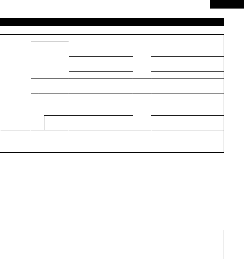
(6) Sound output from this unit digital and analog audio output connectors
2When a disc is played on the ADV-M71 (DIGITAL OUT)
Refer to
page
DVD video
DVD audio
(video part only)
Audio recording format
Dolby Digital
CP : ON
Video CD
CP : OFF
DTS
MPEG audio
48 kHz
•Linear PCM audio is the signal recording format used for music CDs.
While the signals are recorded at 44.1 kHz/16 bit for music CDs, for DVDs they are recorded at 48 kHz/16 bit to 96 kHz/24 bit, providing higher
sound quality than music CDs.
Music CD
MP3/WMA CD
Linear PCM
96 kHz
32 ~ 48 kHz/16 bit PCM
44.1 kHz/16 bit PCM
44.1 kHz/16 bit PCM
LPCM conversion mode : OFF
LPCM conversion mode : OFF
MPEG 1
Linear PCM
MP3/WMA
LPCM conversion mode : ON
LPCM conversion mode : ON
LPCM conversion mode : OFF
Digital out : PCM conversion
Digital out : Normal
Digital out : PCM conversion
Digital out : Normal
Digital out : PCM conversion
Digital out : Normal
Settings
96 kHz PCM (when not copy-protected)
48 kHz/16 bit PCM (when copy-protected)
48 kHz/16 bit PCM
48 kHz/16 bit PCM
48 kHz/16 ~24 bit PCM
2 channels PCM data (48 kHz/16bit)
DTS bitstream
2 channels PCM data (48 kHz/16bit)
2 channels PCM data (48 kHz/16bit)
2 channels PCM data (48 kHz/16bit)
Dolby Digital bitstream
Digital audio data output
101
101
101
2About the LINE-1 and LINE-2 analog recording outputs
When the DVD or the D.AUX digital input is selected:
•Dolby Digital, DTS and PCM digital signals are automatically converted to 2-channel stereo signals before being output (except when in the
Dolby Headphone mode) and can be recorded in analog. (For what happens in the Dolby Headphone mode, see below.)
When TUNER, LINE-1 or LINE-2 is selected:
•The selected analog audio signals from the tuner or from the device connected to the LINE-1 or LINE-2 analog input terminals (IN) are output
unchanged, regardless of the ADV-M71’s input mode or surround mode. (The same is true for the device connected to the D.AUX terminals
when “LINE-2” under “⁄0 SETTING UP THE SYSTEM – (3) Detailed system setup – [6] Function settings” is set to “D.AUX”.)
Recording output during playback of a DVD or D.AUX digital input source in the Dolby Headphone mode:
•In the Dolby Headphone mode with a DVD or a digital input selected, the Dolby Headphone mode analog audio signals currently being played
are output and can be recorded in analog. (See pages 58 and 59.)
Cautions during analog recording of DVDs or digital input sources:
•Do not switch the ADV-M71’s input mode, surround mode or surround parameters during recording. Doing so will interrupt the sound being
recorded.
We recommend setting the surround mode to “STEREO” or “DIRECT”.
•When using headphones, recording is automatically performed in the Dolby Headphone mode. Do not disconnect the headphones or
switch the headphones mode during recording.

ENGLISH
14
•This unit is equipped with a high-speed protection circuit. The purpose of this circuit is to protect the speakers under circumstances such as
when the output of the power amplifier is inadvertently short-circuited and a large current flows, when the temperature surrounding the unit
becomes unusually high, or when the unit is used at high output over a long period which results in an extreme temperature rise.
When the protection circuit is activated, the speaker output is cut off and the power supply indicator LED flashes. Should this occur, please
follow these steps: be sure to switch off the power of this unit, check whether there are any faults with the wiring of the speaker cables or
input cables, and wait for the unit to cool down if it is very hot. Improve the ventilation condition around the unit and switch the power back
on.
If the protection circuit is activated again even though there are no problems with the wiring or the ventilation around the unit, switch off
the power and contact a DENON service center.
Protector circuit
•The protector circuit may be activated if the set is played for long periods of time at high volumes when speakers with an impedance lower
than the specified impedance (for example speakers with an impedance of lower than 4 Ω/ohms) are connected. If the protector circuit is
activated, the speaker output is cut off. Turn off the set’s power, wait for the set to cool down, improve the ventilation around the set, then
turn the power back on.
Note on speaker impedance
•With this unit’s speaker outputs, signals with the reverse phase of the “+” side output terminal’s signals are also output from the “-” side
output terminal.
Do not connect to a device for switching between multiple speakers (a speaker selector or audio channel selector) or connect in ways other
than described in this manual. Doing so will result in damage.
Cautions on connecting
(7) Speaker system connections
Be sure to turn the amplifier’s power off when connecting the
speaker systems.
•Use the included cables to connect the input terminals on the back
of the speaker systems (see diagram) to the amplifier’s speaker
output terminals. Connect the speaker system for the left channel
amplifier’s “L” terminals, the one for the right channel to the
amplifier’s “R” terminals, matching the polarities (“≈” and “√”
marks). Inverting the polarities will result in unnatural sound, with
the phase off or no low bass sound. Also check that all two terminal
knobs are tightly fastened.
Connections
(The red terminals on the right side are the “≈” terminals, the black
ones on the left side the “√” terminals.)
Loosen the terminals knobs, insert the cables’
core wires, then tighten the knobs.
Connect to amplifier’s “≈” side. (Copper color)
Connect to amplifier’s
“√” side. (Silver color)
NOTE:
Make sure the core wires do not touch
each other.
Connecting the speaker cords
Use the included connection cords to connect the input terminals on
the backs of the speaker systems (see the diagram at the right) to the
ADV-M71’s speaker output terminals.
•Connect the speaker system for the left channel to the “L”
terminals, the speaker system for the right channel to the “R”
terminals, and be sure the polarities (“+” and “–”) are properly
interconnected.
•Note that if the polarities are inverted, the phase may be off and the
bass sound may be missing, resulting in an unnatural sound. Also
check that both the speaker terminal’s screws are tightly screwed.
Either twist the core wires
firmly or terminate the wires.
qTurn the speaker
terminal
counterclockwis
e to loosen it.
wInsert the cord’s
core wires.
eTurn clockwise to
tighten the
terminal.
15
ENGLISH
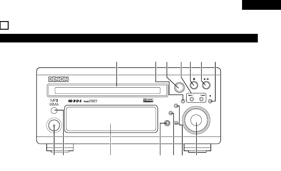
8PART NAMES AND FUNCTIONS
Front Panel
•For details on the functions of these parts, refer to the pages given in parentheses ( ).
B
BAND
PHONES
VOLUME
ON / STANDBY
DVD SURROUND RECEIVER ADV-M71
TONE/SDB
FUNCTION
MENU/SET +
-
SURROUND/ SELECT
PUSH
-
PARAM.
qwertu
oi
!0
!1
!4 !3
y
!2
qPower operation switch (ON/STANDBY)..................................(30)
wRemote control sensor.............................................................(20)
eDisplay
rHeadphones jack (PHONES) ....................................................(58)
tFunction selector (FUNCTION).................................................(44)
yTone/super dynamic bass button (TONE/SDB) ........................(46)
uVolume control (VOLUME) .......................................................(42)
iStop/band button ( 2BAND)..............................................(42, 63)
oPlay/pause button ( 13 ) ...................................................(41, 43)
!0 Open/close button ( 5) ..........................................................(41)
!1 Skip backward and forward buttons
( 8/ – and + / 9) .....................................................(43, 63)
!2 Surround/select knob (SURROUND/SELECT) ..........................(50)
Surround parameter button (PARAMETER) .............................(51)
!3 Menu/set button (MENU/SET) .................................................(65)
!4 Disc holder ...............................................................................(40)

ENGLISH
16
qTransmission indicator
wSleep timer button ...................................................................(93)
eNTSC/PAL button .....................................................................(11)
rClear button..............................................................................(73)
tA-B repeat button.....................................................................(72)
yProgram/direct..........................................................................(73)
uRepeat button...........................................................................(71)
iInput source/surround mode selector button
* System buttons ......................................(18, 19, 21, 22, 23, 28)
oCall button ................................................................................(73)
!0 Test tone button.......................................................................(36)
!1 Input mode selector button......................................................(44)
!2 DVD play button .......................................................................(41)
!3 DVD stop button ......................................................................(42)
!4 DVD skip buttons .....................................................................(43)
!5 DVD search buttons...........................................................(43, 44)
!6 DVD pause button....................................................................(43)
!7 Status button............................................................................(45)
!8 Setup button.............................................................................(30)
!9 Channel select button ..............................................................(36)
@0 Return button ...........................................................................(42)
@1 Display button ..........................................................................(69)
@2 Angle button.............................................................................(83)
@3 Audio selector button...............................................................(81)
@4 Remote control signal transmission window...........................(20)
@5 Power button............................................................................(30)
@6 * System buttons.........................................................(18, 21, 22)
@7 Zoom button.............................................................................(86)
@8 Slide mode button....................................................................(80)
@9 Search mode button.................................................................(43)
#0 Random button.........................................................................(74)
#1 Tuner tuning +/– buttons..........................................................(63)
#2 Tuner preset +/– buttons..........................................................(64)
#3 Function selector button ..........................................................(44)
#4 Surround mode selector button ...............................................(45)
#5 Mode selector switches.....................................................(17, 18)
#6 Main volume control buttons ...................................................(42)
#7 Muting button...........................................................................(46)
#8 Tone/SDB button ......................................................................(46)
#9 Enter button .............................................................................(29)
$0 Cursor button ...........................................................................(29)
$1 Surround parameter button......................................................(50)
$2 Top menu button......................................................................(84)
$3 Menu button.............................................................................(85)
$4 Subtitle button..........................................................................(82)
$5 * System buttons...................................................(18, 21, 22, 28)
Remote control unit
•For details on the functions of these parts, refer to the pages given in parentheses ( ).
•Some of the buttons on the remote control unit have some functions.
The functions are switched using the remote control mode selector switches.
+
-
+
-
RC-966
A / V
3
A-B REPEAT
SEARCH MODE
ONOFF
REPEAT RANDOM
CLEAR ZOOMSLIDE MODE
PROG/ DIRECT
MEMO BAND
RTCTPTYRDS
MODE
STAT U S
RETURN
ANGLE AUDIO
SUB TITLE
SETUP TONE /SDB
FUNCTIONSURROUNDINPUT MODETEST TONE
DVD
TUNER
CH
3
-
+
21
654
987
0/10
CALL
ENTER
MUTING
+10
DISPLAY MENU
TOP MENU
SYSTEM MD
CDR TAPE
TUNER TV / VCR
SURROUND
PARAMETER
CH SELECT
VCR
NTSC/PAL
SLEEP
ENTER
CD SRS
EDIT/MENUCHARAC.
REC
TIMETITLE
TUNING /
TV VOL
TV CH TV CH
TUNERDVD
MD/ LINE-1 TAPE/ LINE-2
AUTO DECODE
VIRTUALDIRECT
5CH STEREO
STEREO
D.AUX
-
+
VCR CH
IN/SURR.
IN/SURR.
DVD
T VT V INSOURCE
9
8
21
76
+
-
q
w
e
r
t
y
u
i
o
!0
!1
!2
!3
!4
!5
!6
!7
!8
!9
@0
@1
@2
@3
@4
@5
@6
@7
@8
@9
#0
#1
#2
#3
#4
#5
#7
#8
#9
$0
$1
$2
$3
$4
$5
#6
•For details on the function and operation of the various parts, refer to the pages indicated in (parentheses).
•Buttons indicated are DVD control buttons and can be operated when the remote control mode selector switch is set to the and
position.
•The functions of the system buttons (*) are switched using the remote control mode selector switch.
DVD
A / V

17
ENGLISH
Names and functions of remote control unit buttons on the ADV-M71
•Buttons in sections q~ ecan be operated regardless of the position of mode switches 1 and 2.
•Consider and as standard positions, and switch as necessary to operate.
DVD
A / V
+
-
+
-
RC-966
A / V
3
A-B REPEAT
SEARCH MODE
ONOFF
REPEAT RANDOM
CLEAR ZOOMSLIDE MODE
PROG/ DIRECT
MEMO BANDMODE
STAT US
RETURN
ANGLE AUDIO
SUB TITLE
SETUP TONE /SDB
FUNCTIONSURROUNDINPUT MODETEST TONE
DVD
TUNER
CH
3
-
+
21
654
987
0/10
CALL
ENTER
MUTING
+10
DISPLAY MENU
TOP MENU
SYSTEM MD
CDR TAPE
TUNER TV / VCR
SURROUND
PARAMETER
CH SELECT
VCR
NTSC/PAL
SLEEP
ENTER
CD SRS
EDIT/MENUCHARAC.
REC
TIMETITLE
TUNING /
TV VOL
TV CH TV CH
TUNERDVD
MD/ LINE-1 TAPE/ LINE-2
AUTO DECODE
VIRTUALDIRECT
5CH STEREO
STEREO
D.AUX
-
+
VCR CH
IN/SURR.
IN/SURR.
DVD
T VTV INSOURCE
9
8
21
76
+
-
RTCT
PTYRDS
3
12
q
w
e
q
q
1
2
Set mode switch 1 to the “A/V” position.
Set mode switch 2 to the position of the function you want to
operate (DVD, TUNER or IN/SURR.).
A / V
SYSTEM
TUNER TV / VCR
IN/SURR.
DVD
qSurround amplifier control buttons
ON : Turns the ADV-M71’s power on.
OFF : Turns the ADV-M71’s power off.
FUNCTION : Function selection (in order)
SURROUND : Surround mode selection
INPUT MODE : Input mode selection
TEST TONE : Test tone on/off
+ : Main volume up
–: Main volume down
MUTING : Muting on/off
STATUS : Status display selection
TONE/SDB : Tone/SDB selection and setting
SURROUND : Surround parameter selection and setting
PARAMETER
SET UP : Setup mode on/off
CH SELECT : Channel level selection and setting
•, ª, 0, 1: Cursor up, down, left and right
ENTER : Enter setting
wDVD control buttons
1: Play (auto power on and auto function selection)
2: Stop
8, 9: Skip (cueing)
6, 7: Search (fast-reverse and fast-forward)
3: Pause and frame-by-frame
eTuner control buttons
CH +/–: Preset channel up/down
(auto power on and auto function selection)
ENGLISH
18
3Operate the ADV-M71.
[1] Surround amplifier system buttons
(Operated with mode switch 2 set to “IN/SURR.”)
•These operations are possible with mode switch 1 at
any position.
The operations in gray print can be performed.
+
-
+
-
RC-966
A / V
3
A-B REPEAT
SEARCH MODE
ONOFF
REPEAT RANDOM
CLEAR ZOOMSLIDE MODE
PROG/ DIRECT
MEMO BANDMODE
STAT US
RETURN
ANGLE AUDIO
SUB TITLE
SETUP TONE /SDB
FUNCTIONSURROUNDINPUT MODETEST TONE
DVD
TUNER
CH
3
-
+
21
654
987
0/10
CALL
ENTER
MUTING
+10
DISPLAY MENU
TOP MENU
SYSTEM MD
CDR TAPE
TUNER TV / VCR
SURROUND
PARAMETER
CH SELECT
VCR
NTSC/PAL
SLEEP
ENTER
CD SRS
EDIT/MENUCHARAC.
REC
TIMETITLE
TUNING /
TV VOL
TV CH TV CH
TUNERDVD
MD/ LINE-1 TAPE/ LINE-2
AUTO DECODE
VIRTUALDIRECT
5CH STEREO
STEREO
D.AUX
-
+
VCR CH
IN/SURR.
IN/SURR.
DVD
T VTV INSOURCE
9
8
21
76
+
-
RTCT
PTYRDS
SLEEP : Sleep on/off
DVD : Function DVD
TUNER : Function TUNER
D.AUX : Function D.AUX
MD/LINE-1 : Function MD/LINE-1
TAPE/LINE-2 : Function TAPE/LINE-2
5CH STEREO : 5-channel stereo surround mode
(when “5.1CH” selected in setup)
AUTO DECODE
: 2-channel mode switching when auto
decode surround mode set
(when “5.1CH” selected in setup)
VIRTUAL : 2-channel mode switching when Dolby
Virtual Speaker or Dolby VS surround mode
set
STEREO : Stereo mode
DIRECT : Direct mode
[2] DVD system buttons
(Operated with mode switch 2 set to “DVD”)
+
-
+
-
RC-966
A / V
3
A-B REPEAT
SEARCH MODE
ONOFF
REPEAT RANDOM
CLEAR ZOOMSLIDE MODE
PROG/ DIRECT
MEMO BANDMODE
STAT US
RETURN
ANGLE AUDIO
SUB TITLE
SETUP TONE /SDB
FUNCTIONSURROUNDINPUT MODETEST TONE
DVD
TUNER
CH
3
-
+
21
654
987
0/10
CALL
ENTER
MUTING
+10
DISPLAY MENU
TOP MENU
SYSTEM MD
CDR TAPE
TUNER TV / VCR
SURROUND
PARAMETER
CH SELECT
VCR
NTSC/PAL
SLEEP
ENTER EDIT/MENUCHARAC.
REC
TIMETITLE
TUNING /
TV VOL
TV CH TV CH
TUNERDVD
MD/ LINE-1 TAPE/ LINE-2
AUTO DECODE
VIRTUALDIRECT
5CH STEREO
STEREO
D.AUX
-
+
VCR CH
IN/SURR.
IN/SURR.
DVD
T VTV INSOURCE
9
8
21
76
+
-
CD SRS
RTCT
PTYRDS
NTSC/PAL : NTSC/PAL selection
ZOOM : Zoom on/off
SLIDE MODE : JPEG image slide mode selection
A-B REPEAT : A-B repeat playback setting
CLEAR : Program clear
SEARCH MODE
: Title and chapter search selection
RANDOM : Random play on/off
REPEAT : Repeat play setting
PROG/DIRECT : Program/direct play selection
CALL : Program call
0 ~ 9, +10 : Number buttons
TOP MENU : Top menu call
MENU : Menu call
DISPLAY : Display call/selection
RETURN : Menu return
SUBTITLE : Subtitle language selection
AUDIO : Audio language selection
ANGLE : Angle selection
19
ENGLISH
3[3] Tuner system buttons
(Operated with mode switch 2 set to “TUNER”)
+
-
+
-
RC-966
A / V
3
A-B REPEAT
SEARCH MODE
ONOFF
REPEAT RANDOM
CLEAR ZOOMSLIDE MODE
PROG/ DIRECT
MEMO BANDMODE
STAT US
RETURN
ANGLE AUDIO
SUB TITLE
SETUP TONE /SDB
FUNCTIONSURROUNDINPUT MODETEST TONE
DVD
TUNER
CH
3
-
+
21
654
987
0/10
CALL
ENTER
MUTING
+10
DISPLAY MENU
TOP MENU
SYSTEM MD
CDR TAPE
TUNER TV / VCR
SURROUND
PARAMETER
CH SELECT
VCR
NTSC/PAL
SLEEP
ENTER EDIT/MENUCHARAC.
REC
TIMETITLE
TUNING /
TV VOL
TV CH TV CH
TUNERDVD
MD/ LINE-1 TAPE/ LINE-2
AUTO DECODE
VIRTUALDIRECT
5CH STEREO
STEREO
D.AUX
-
+
VCR CH
IN/SURR.
IN/SURR.
DVD
T VTV INSOURCE
9
8
21
76
+
-
CD SRS
RTCT
PTYRDS
BAND : FM/AM band selection
MEMO : Preset memory
MODE : FM auto/mono mode selection
TUNER +/–: Tuning up/down
1 ~ 10, +10 : Preset channel number buttons
RDS PTY TP
1 1 1
OFF 0
PTY : Press this button after selecting“PTY” with the RDS
button to select one of the 29 program types.
CT : Use this to correct the time of the clock on the ADV-
M71. Press this button when the time service of an
RDS station is being properly received. “TIME” is
displayed for 2 seconds and the ADV-M71’s clock is
corrected. “NO TIME DATA” is displayed if the RDS
station does not offer a time service and when the
broadcast is not being received properly.
RT : Press this button when receiving RDS stations to
select the frequency, PS (or Station name), PTY or
RT display.
Note that this button will not function if the
reception is poor.
The display mode changes as follows each time the
button is pressed.
RDS : Use this button to automatically tune to stations
using the radio data system.
PS (or Station name) RT PTY
1 1 1
Frequency 0
The station name is displayed with priority instead of the
PS display when a channel whose station name has been
preset is tuned in.

ENGLISH
20
9REMOTE CONTROL UNIT
•The included remote control unit (RC-966) can be used to operate not only this unit but other remote control compatible DENON components
as well. In addition, the memory contains the control signals for other remote control units, so it can be used to operate non-DENON remote
control compatible products.
(1) Inserting the batteries
qRemove the remote control unit’s rear cover.
wSet three R6P/AA batteries in the battery compartment in the
indicated direction.
ePut the rear cover back on.
Notes on Batteries
•Use R6P/AA batteries in the remote control unit.
•The batteries should be replaced with new ones approximately
once a year, though this depends on the frequency of usage.
•Even if less than a year has passed, replace the batteries with new
ones if the set does not operate even when the remote control unit
is operated nearby the set. (The included battery is only for verifying
operation. Replace it with a new battery as soon as possible.)
•When inserting the batteries, be sure to do so in the proper
direction, following the “≈” and “√” marks in the battery
compartment.
•To prevent damage or leakage of battery fluid:
•Do not use a new battery together with an old one.
•Do not use two different types of batteries.
•Do not short-circuit, disassemble, heat or dispose of batteries in
flames.
•Remove the batteries from the remote control unit when you do
not plan to use it for an extended period of time.
•If the battery fluid should leak, carefully wipe the fluid off the inside
of the battery compartment and insert new batteries.
•When replacing the batteries, have the new batteries ready and
insert them as quickly as possible.
(2) Using the remote control unit
B
+
-
+
-
RC-936
A / V
3
A-B REPEAT
SEARCH MODE
ON
OFF
REPEATRANDOM
CLEARZOOM
SLIDE MODE
PROG/DIRECT
MEMOBAND
MODE
ST
A
TUS
RETURN
ANGLEAUDIO
SUB TITLE
SETUPTONE/SDB
FUNCTION
SURROUND
INPUT MODE
TEST TONE
DVD
TUNER
CH
3
-
+
2
1
6
5
4
9
8
7
0
/10
CALL
ENTER
MUTING
+10
DISPLAYMENU
TOP MENU
SYSTEMMD
CDRT
APE
TUNERTV / VCR
SURROUND
PARAMETER
CH SELECT
VCR
NTSC/PAL
SLEEP
ENTER
CD SRS
EDIT/MENU
CHARAC.
REC
TIME
TITLE
TUNING /
TV VOL
TV CHTV CH
TUNER
DVD
MD/LINE-1T
APE/LINE-2
AUTO DECODE
VIRTUAL
DIRECT
5CH STEREO
STEREO
D.AUX
-
+
VCR CH
IN/SURR.
IN/SURR.
DVD
T V
TV IN
SOURCE
+
-
9
8
21
7
6
•Point the remote control unit at the remote sensor on the main unit
as shown on the diagram.
•The remote control unit can be used from a straight distance of
approximately 7 meters/22 feet from the main unit, but this
distance will be shorter if there are obstacles in the way or if the
remote control unit is not pointed directly at the remote sensor.
•The remote control unit can be operated at a horizontal angle of up
to 30 degrees with respect to the remote sensor.
NOTES:
•It may be difficult to operate the remote control unit if the remote
sensor is exposed to direct sunlight or strong artificial light.
•Do not press buttons on the main unit and remote control unit
simultaneously. Doing so may result in malfunction.
•Neon signs or other devices emitting pulse-type noise nearby may
result in malfunction, so keep the set as far away from such
devices as possible.
Approx. 7m / 22 feet
30°
30°

21
ENGLISH
•The included remote control unit (RC-966) can be used to operate
not only the ADV-M71 but also to perform system operations for
the D-M31 series and to operate other remote control compatible
DENON products. In addition, the remote control operation codes
of other major brands of TVs and video decks are also stored in the
remote control unit, so the unit can be used to operate these TVs
and video decks as well.
(3) Operating DENON audio components
•Turn on the power of all the components before operating them.
•Depending on the model and year of make of your component,
some of the keys may not work.
+
-
+
-
RC-966
A / V
3
A-B REPEAT
SEARCH MODE
ONOFF
REPEAT RANDOM
CLEAR ZOOMSLIDE MODE
PROG/ DIRECT
MEMO BANDMODE
STAT US
RETURN
ANGLE AUDIO
SUB TITLE
SETUP TONE /SDB
FUNCTIONSURROUNDINPUT MODETEST TONE
DVD
TUNER
CH
3
-
+
21
654
987
0/10
CALL
ENTER
MUTING
+10
DISPLAY MENU
TOP MENU
SYSTEM MD
CDR TAPE
TUNER TV / VCR
SURROUND
PARAMETER
CH SELECT
VCR
NTSC/PAL
SLEEP
ENTER EDIT/MENUCHARAC.
REC
TIMETITLE
TUNING /
TV VOL
TV CH TV CH
TUNERDVD
MD/ LINE-1 TAPE/ LINE-2
AUTO DECODE
VIRTUALDIRECT
5CH STEREO
STEREO
D.AUX
-
+
VCR CH
IN/SURR.
IN/SURR.
DVD
T VTV INSOURCE
9
8
21
76
+
-
CD SRS
RTCT
PTYRDS
3
12
3
1
2
3
Set mode switch 1 to the “SYSTEM” position.
(Blue print)
Set mode switch 2 to the position for the component to be
operated (MD, CDR or TAPE).
(Blue print)
Operate the audio component.
•For details, refer to the component’s operating instructions.
Operation may not be possible for some models.
A / V
SYSTEM
MD
CDR TAPE
TUNER TV / VCR
IN/SURR.
IN/SURR.
DVD
3[1] MD recorder system buttons
(operated with mode switch 2 set to “MD”)
+
-
+
-
A/V
A-B REPEAT
SEARCH MODE
ONOFF
REPEAT RANDOM
CLEAR ZOOMSLIDE MODE
PROG/ DIRECT
MEMO BANDMODE
FUNCTIONSURROUNDINPUT MODETEST TONE
TUNER
CH
3
-
+
21
654
987
0/10
CALL
+10
TUNER TV / VCR
VCR
NTSC/PAL
SLEEP
ENTER
CD SRS
EDIT/MENUCHARAC.
REC
TIMETITLE
TUNING /
TV VOL
TV CH TV CH
TUNERDVD
MD/ LINE-1 TAPE/ LINE-2
AUTO DECODE
VIRTUALDIRECT
5CH STEREO
STEREO
D.AUX
IN/SURR
DVD
T VTV INSOURCE
RTCT
PTYRDS
TIME : Disc time display
TITLE : Name display
REC : Recording (multi-recording function with the DMD-
M31)
SOURCE : MD power on/off
EDIT/MENU : Edit mode selection
CHARAC : Selection of characters when inputting names
ENTER : Entering of edited values
CD SRS : CD synchronized recording (DMD-M31 system
function)
CLEAR : Program clearing
RANDOM : Random play on/off
REPEAT : Repeat play setting
PROG/DIRECT : Program/direct playback selection
CALL : Program calling
1~10, +10 : Track number selection
8, 9: Auto search (cueing)
6, 7: Manual search (fast-reverse and fast-forward)
1(/ 3) : Play (play/pause, auto power on and auto function
selector with the DMD-M31)
3: Pause
2: Stop
RC-966
RETURN
ANGLE AUDIO
SUB TITLE
DISPLAY MENU
TOP MENU
SURROUND
PARAMETER
CH SELECT
-
+
VCR CH

ENGLISH
22
[2] CD recorder system buttons
(operated with mode switch 2 set to “CDR”)
+
-
+
-
A/V
A-B REPEAT
SEARCH MODE
ONOFF
REPEAT RANDOM
CLEAR ZOOMSLIDE MODE
PROG/ DIRECT
MEMO BANDMODE
FUNCTIONSURROUNDINPUT MODETEST TONE
TUNER
CH
3
-
+
21
654
987
0/10
CALL
+10
TUNER TV / VCR
VCR
NTSC/PAL
SLEEP
ENTER
CD SRS
EDIT/MENUCHARAC.
REC
TIMETITLE
TUNING /
TV VOL
TV CH TV CH
TUNERDVD
MD/ LINE-1 TAPE/ LINE-2
AUTO DECODE
VIRTUALDIRECT
5CH STEREO
STEREO
D.AUX
IN/SURR
DVD
T VTV INSOURCE
RTCT
PTYRDS
TIME : Disc time display
TITLE : Name display and selection of characters when
inputting names
REC : Recording
SOURCE : CD recorder power on/off
EDIT/MENU : Menu selection
ENTER : Entering of menu items
CLEAR : Program clearing
RANDOM : Random play on/off
REPEAT : Repeat play setting
PROG/DIRECT : Program/direct playback selection
CALL : Program calling
1~10, +10 : Track number selection
8, 9: Auto search (cueing)
6, 7: Manual search (fast-reverse and fast-forward)
1(/ 3) : Play (play/pause, auto power on and auto function
selection with the CDR-M30)
3: Pause
2: Stop
[3] Tape deck system button
(operated with mode switch 2 set to “TAPE”)
A-B REPEAT
SEARCH MODE
ONOFF
REPEAT RANDOM
CLEAR ZOOMSLIDE MODE
PROG/ DIRECT
MEMO BANDMODE
-
+
VCR
NTSC/PAL
SLEEP
ENTER
CD SRS
EDIT/MENUCHARAC.
REC
TIMETITLE
TUNING /
TV VOL
TV CH TV CH
TUNERDVD D.AUX
T VTV INSOURCE
RTCT
PTYRDS
REC : Recording
CD SRS : CD synchronized recording (DRR-M31 system
function)
6, 7: Rewind and fast-forward
1: Forward direction play
0TAPE : Reverse direction play (0and 1: auto power on
and auto function selection with the DRR-M31)
RC-966
RETURN
ANGLE AUDIO
SUB TITLE
DISPLAY MENU
TOP MENU
SURROUND
PARAMETER
CH SELECT
-
+
VCR CH
RC-966
RETURN
ANGLE AUDIO
SUB TITLE
DISPLAY MENU
TOP MENU
SURROUND
PARAMETER
CH SELECT
-
+
VCR CH

23
ENGLISH
(4) TV and video deck preset memories
•Components of other brands can be operated with the included
remote control unit by storing their codes in the preset memory.
Note that depending on the model some operations may not be
possible and some buttons may not operate properly.
+
-
+
-
RC-966
A / V
3
A-B REPEAT
SEARCH MODE
ONOFF
REPEAT RANDOM
CLEAR ZOOMSLIDE MODE
PROG/ DIRECT
MEMO BANDMODE
STAT US
RETURN
ANGLE AUDIO
SUB TITLE
SETUP TONE /SDB
FUNCTIONSURROUNDINPUT MODETEST TONE
DVD
TUNER
CH
3
-
+
21
654
987
0/10
CALL
ENTER
MUTING
+10
DISPLAY MENU
TOP MENU
SYSTEM MD
CDR TAPE
TUNER TV / VCR
SURROUND
PARAMETER
CH SELECT
VCR
NTSC/PAL
SLEEP
ENTER EDIT/MENUCHARAC.
REC
TIMETITLE
TUNING /
TV VOL
TV CH TV CH
TUNERDVD
MD/ LINE-1 TAPE/ LINE-2
AUTO DECODE
VIRTUALDIRECT
5CH STEREO
STEREO
D.AUX
-
+
VCR CH
IN/SURR.
IN/SURR.
DVD
T VTV INSOURCE
9
8
21
76
+
-
CD SRS
RTCT
PTYRDS
4
33
4
4
12
2Not set upon shipment from the factory.
1
2
3
4
Set mode switch 1 to the “A/V” position.
Set mode switch 2 to the “TV/VCR” position.
Press the power ON button and the OFF button simultaneously.
•The transmission LED (indicator) flashes.
Press the TV button to preset a TV, the VCR button to preset
a video deck, then input the 3-digit number corresponding to
the brand of the component whose signals are to be stored in
the preset memory (refer to the tables of remote control
codes on pages 24 to 27).
A / V
SYSTEM
MD
CDR TAPE
TUNER TV / VCR
IN/SURR.
IN/SURR.
DVD
OFF ON
TIME
T V
NOTES:
•When buttons are pressed while setting the preset memory,
their signals are sent from the remote control transmitter, so
cover the remote control sensor when setting the preset
memory to prevent accidental operation.
•
Depending on the model and year of make, some of the remote control
codes for the brands included on the tables may not operate properly.
•
For some brands there are multiple types of remote control codes. If
an operation does not work, try changing to one of the other codes.
VCR
NTSC/PAL
REC
321
654
987
0/10
TUNERDVD
MD/ LINE-1 TAPE/ LINE-2
AUTO DECODE5CH STEREO
STEREO
D.AUX

ENGLISH
24
Combinations of preset codes for different brands
Fujitsu 004, 062
Funai 004, 062
Futuretech 004
GE 020, 036, 037, 040, 044, 058, 066, 088, 119, 120,
125, 147
Goldstar 015, 029, 031, 039, 048, 051, 056, 057, 067,
068, 069, 116, 165
Grundy 062
Hitachi 029, 031, 051, 052, 070, 111, 112, 113, 124, 134
Hitachi Pay TV 151
Infinity 017, 071
Janeil 122
JBL 017, 071
JC Penny 020, 034, 039, 040, 041, 044, 048, 050,058, 066,
069, 076, 088, 090, 095, 125, 136, 159
JCB 046
JVC 019, 051, 052, 072, 073, 091, 117, 126
Kawasho 018, 046
Kenwood 038, 056, 057
Kloss 010, 032
Kloss Novabeam 005, 122, 127, 131
KTV 074, 123
Loewe 071
Logik 144
Luxman 031
LXI 008, 014, 017, 024, 040, 044, 063, 071, 075, 076,
077, 118, 125
Magnavox 005, 010, 017, 030, 033, 038, 050, 056, 071, 078,
079, 085, 089, 108, 109, 110, 127, 131, 132, 145
Marantz 015, 017, 071, 080
Matsui 027
Memorex 014, 027, 045, 083, 118, 144
Metz 160, 161, 162, 163, 164
MGA 001, 039, 048, 056, 057, 058, 065 081, 083
Midland 125
Minutz 066
Mitsubishi 001, 016, 039, 048, 056, 057, 058, 065, 081, 082,
083, 105
Montgomery Ward
011, 020, 144, 145, 146
Motorola 121, 147
MTC 031, 034, 039, 048, 095
NAD 008, 075, 076, 128
National 002, 036, 061, 147
TV
Admiral 045, 121
Adventura 122
Aiko 054
Akai 016, 027, 046
Alleron 062
A-Mark 007
Amtron 061
Anam 006, 007, 036
Anam National 061, 147
AOC 003, 007, 033, 038, 039, 047, 048, 049, 133
Archer 007
Audiovox 007, 061
Bauer 155
Belcor 047
Bell & Howell 045, 118
Bradford 061
Brockwood 003, 047
Candle 003, 030, 031, 032, 038, 047, 049, 050, 122
Capehart 003
Celebrity 046
Circuit City 003
Citizen 029, 030, 031, 032, 034, 038, 047, 049, 050, 054,
061, 095, 122, 123
Concerto 031, 047, 049
Colortyme 003, 047, 049, 135
Contec 013, 051, 052, 061
Cony 051, 052, 061
Craig 004, 061
Crown 029
Curtis Mathes 029, 034, 038, 044, 047, 049, 053, 095, 118
Daewoo 027, 029, 039, 048, 049, 054, 055, 106, 107, 137
Daytron 003, 049
Dimensia 044
Dixi 007, 015, 027
Electroband 046
Electrohome 029, 056, 057, 058, 147
Elta 027
Emerson 029, 051, 059, 060, 061, 062, 118, 123, 124, 139, 148
Envision 038
Etron 027
Fisher 014, 021, 063, 064, 065, 118
Formenti 155
Fortress 012

25
ENGLISH
National Quenties
002
NEC 031, 038, 039, 048, 057, 084, 086, 135, 147
Nikko 054
NTC 054
Optimus 128
Optonica 011, 012, 093, 121
Orion 004, 139
Panasonic 002, 009, 017, 036, 037, 071, 141, 143, 147
Philco 005, 010, 030, 050, 051, 056, 079, 085, 127, 131,
132, 145, 147
Philips 005, 015, 017, 050, 051, 056, 078, 087, 088, 089,
131, 132, 147
Pioneer 124, 128, 142
Portland 054
Price Club 095
Proscan 040, 044, 125
Proton 035, 051, 092, 129
Pulsar 042
Quasar 036, 037, 074, 141
Radio Shack 011, 044, 063, 093, 118
RCA 040, 044, 125, 130, 137, 151, 152
Realistic 014, 063, 093, 118
Saisho 027
Samsung 003, 015, 034, 053, 055, 057, 094, 095, 136,153
Sansui 139
Sanyo 013, 014, 021, 022, 063, 064, 081, 096
SBR 015
Schneider 015
Scott 062
Sears 008, 014, 021, 022, 023, 024, 025, 040, 052, 057,
062, 063, 064, 065, 073, 075, 076,
097, 098, 125, 159
Sharp 011, 012, 013, 026, 093, 099, 100, 104, 121
Siemens 013
Signature 045, 144
Simpson 050
Sony 043, 046, 138, 146, 150
Soundesign 030, 050, 062
Spectricon 007, 033
Squareview 004
Supre-Macy 032, 122
Supreme 046
Sylvania 005, 010, 017, 030, 078, 079, 085, 089, 101, 127,
131, 132, 145, 155
Symphonic 004, 148
Tandy 012, 121
Tatung 036, 124
Technics 037
Teknika 001, 030, 032, 034, 052, 054, 078, 083, 095, 144,
156, 157
Tera 035, 129
Toshiba 008, 014, 034, 063, 075, 076, 095, 097, 136, 158,
159
Universal 020, 066, 088
Victor 019, 073, 126
Video Concepts 016
Viking 032, 122
Wards 005, 045, 066, 078, 085, 088, 089, 093, 102, 103,
131, 132, 148
Zenith 042, 114, 115, 140, 144, 149
Zonda 007

ENGLISH
26
VCR
Admiral 081
Aiko 095
Aiwa 009
Akai 026, 027, 070, 072, 082, 083, 084
Alba 055
Amstrad 009
ASA 042
Asha 087
Audio Dynamic 005, 085
Audiovox 088
Beaumark 087
Broksonic 086, 093
Calix 088
Candle 006, 087, 088, 089, 090
Canon 049, 057
Capehart 025, 055, 056, 071
Carver 015
CCE 095
Citizen 006, 007, 087, 088, 089, 090, 095
Craig 007, 087, 088, 091, 115
Curtis Mathes 006, 049, 073, 080, 087, 090, 092
Cybernex 087
Daewoo 025, 055, 059, 074, 089, 093, 095, 096
Daytron 025, 055
DBX 005, 085
Dumont 053
Dynatech 009
Electrohome 001, 088, 097
Electrophonic 088
Emerson 001, 009, 017, 027, 086, 088, 089, 092, 093, 097,
100, 101, 102, 103, 104, 117
Fisher 009, 028, 031, 053, 054, 091, 098, 099, 115
GE 007, 011, 049, 050, 051, 052, 073, 080, 087
Go Video 047, 048
Goldstar 006, 012, 062, 088, 129
Gradiente 094
Grundig 042
Harley Davidson 094
Harman Kardon 040, 062
Hi-Q 091
Hitachi 009, 013, 023, 026, 058, 108, 109, 110, 111
JC Penny 004, 005, 007, 023, 028, 049, 062,
085, 087, 088
Jensen 013, 026
JVC 004, 005, 006, 026, 029, 043, 044, 045, 046, 085
Kenwood 004, 005, 006, 026, 029, 033, 045, 085, 090
Kodak 088
Lloyd 009, 094
LXI 088
Magnavox 015, 016, 042, 049, 063, 106
Magnin 087
Marantz 004, 005, 006, 015, 042, 049, 085, 090
Marta 088
MEI 049
Memorex 009, 033, 049, 053, 060, 081, 087, 088, 091, 094,
115
Metz 123, 124, 125, 126, 127, 128
MGA 001, 017, 027, 041, 097
MGN Technology 087
Midland 011
Minolta 013, 023
Mitsubishi 001, 003, 008, 013, 014, 017, 027, 029, 039, 040,
041, 045, 097
Motorola 081
Montgomery Ward
001, 002, 007, 009, 049, 063, 081, 115, 117
MTC 009, 087, 094
Multitech 007, 009, 011, 087, 090, 094
NAD 038
NEC 004, 005, 006, 018, 026, 029, 045, 061, 062, 085
Nikko 088
Noblex 087
Optimus 081, 088
Optonica 021
Panasonic 024, 049, 064, 066, 067, 068, 069, 107
Perdio 009
Pentax 006, 013, 023, 058, 090
Philco 015, 016, 049
Philips 015, 021, 042, 049, 105
Pilot 088
Pioneer 005, 013, 029, 036, 037, 038, 045, 085
Portland 025, 055, 090
Proscan 063, 080
Pulsar 060
Quartz 033
Quasar 034, 035, 049
Radio Shack 001, 002, 021, 081, 087, 088, 091, 094, 097, 098,
115
Radix 088

27
ENGLISH
Randex 088
RCA 007, 013, 019, 023, 058, 063, 064, 065, 073, 080,
082, 087
Realistic 009, 021, 031, 033, 049, 053, 081, 087, 088, 091,
094, 097, 098
Ricoh 055
Salora 033, 041
Samsung 007, 011, 051, 059, 070, 083, 087, 089, 113
Sanky 081
Sansui 005, 026, 029, 045, 061, 085, 114
Sanyo 032, 033, 053, 087, 091, 115, 116
SBR 042
Scott 017, 020, 086, 089, 093, 117
Sears 013, 023, 028, 031, 033, 053, 054, 088, 091, 098,
099, 115
Sentra 055
Sharp 001, 002, 021, 097
Shogun 087
Sony 075, 076, 077, 078, 079, 121, 122
STS 023
Sylvania 009, 015, 016, 017, 041, 049, 094
Symphonic 009, 094
Tandy 009
Tashiko 009, 088
Tatung 004, 026, 030
Teac 004, 009, 026, 094
Technics 024, 049
Teknika 009, 010, 022, 049, 088, 094
TMK 087, 092
Toshiba 013, 017, 020, 041, 059, 089, 098, 099, 117
Totevision 007, 087, 088
Unirech 087
Vecrtor Research 005, 062, 085, 089, 090
Victor 005, 045, 046, 085
Video Concepts 005, 027, 085, 089, 090
Videosonic 007, 087
Wards 013, 021, 023, 087, 088, 089, 091, 094, 097, 118,
119, 120
XR-1000 094
Yamaha 004, 005, 006, 026, 062, 085
Zenith 060, 078, 079

ENGLISH
28
(5) Operating the TV/video deck after storing its remote control signals in the preset memory
+
-
+
-
RC-966
A / V
3
A-B REPEAT
SEARCH MODE
ONOFF
REPEAT RANDOM
CLEAR ZOOMSLIDE MODE
PROG/ DIRECT
MEMO BANDMODE
STAT US
RETURN
ANGLE AUDIO
SUB TITLE
SETUP TONE /SDB
FUNCTIONSURROUNDINPUT MODETEST TONE
DVD
TUNER
CH
3
-
+
21
654
987
0/10
CALL
ENTER
MUTING
+10
DISPLAY MENU
TOP MENU
SYSTEM MD
CDR TAPE
TUNER TV / VCR
SURROUND
PARAMETER
CH SELECT
VCR
NTSC/PAL
SLEEP
ENTER EDIT/MENUCHARAC.
REC
TIMETITLE
TUNING /
TV VOL
TV CH TV CH
TUNERDVD
MD/ LINE-1 TAPE/ LINE-2
AUTO DECODE
VIRTUALDIRECT
5CH STEREO
STEREO
D.AUX
-
+
VCR CH
IN/SURR.
IN/SURR.
DVD
T VTV INSOURCE
9
8
21
76
+
-
CD SRS
RTCT
PTYRDS
3
-q
3
-w
12
3
-w
3
-q
1
2
3
Set mode switch 1 to the “A/V” position.
Set mode switch 2 to the “TV/VCR” position.
Operate the video component.
•For details, refer to the component’s operating instructions.
It may not be possible to operate some models.
A / V
SYSTEM
MD
CDR TAPE
TUNER TV / VCR
IN/SURR.
IN/SURR.
DVD
NOTE:
•The TV’s “TV (POWER)” and “TV IN” buttons can be operated as
long as mode switch 1 is set to the “A/V” position, regardless of
the position of mode switch 2.
3Monitor TV (TV) and video deck (VCR) system buttons
qTV system buttons
TV : Power on/off
0~9 : Channel numbers
TV IN : TV input switching
TV VOL +, –: Volume up/down
TV CH +, –: Channel switching
wVideo deck system buttons
VCR : Power on/off
VCR CH +, –: Channel switching
6, 7: Manual search (fast-forward and fast-backward)
1: Play
3: Pause
2: Stop

29
ENGLISH
Speaker
2CH Virtual
Set the screen size and the speaker system.
TV Aspect
4:3 PS
LINE-1 LINE-2 REC OUT
MD TAPE ON
Function Assignment Set the LINE-1 and LINE-2 function names and turn the
analog recording output (REC OUT) on or off.
3
STAT U S
RETURN
ANGLE AUDIO
SUB TITLE
SETUP TONE/ SDB
ENTER
MUTING
DISPLAY MENU
TOP MENU
SURROUND
PARAMETER
CH SELECT
-
+
VCR CH
76
-
10 SETTING UP THE SYSTEM
•Once all connections with other AV components have been completed as described in “CONNECTIONS” (see pages 8 to 14), make the various
settings described below on the monitor screen using the ADV-M71’s on-screen display function.
•Use the following buttons to set up the system:
System setup items and default values (set upon shipment from the factory)
Setup
Quick set up
Speaker Configuration
Delay Time
Channel Level
AV1 VIDEO OUTPUT
DVD auto power off setting
Disc Setup
OSD Setup
Video Setup
Audio Setup
Ratings
Other Setup
Input the combination of speakers in your system and
their corresponding sizes (SMALL for regular speakers,
LARGE for full-size, full-range) to automatically set the
composition of the signals output from the speakers and the
frequency response.
This parameter is for optimizing the timing with which the
audio signals are produced from the speakers and subwoofer
according to the listening position.
At the listening position, listen to the test tones output
from the different speakers and set so that the playback
level from the different speakers is equal.
To select whether composite video signals or S video signals
or RGB signals will be output from the AV1 SCART terminals.
The power automatically switches to standby if no
operation is performed for 30 minutes while in the stop
mode with the function set to DVD.
Set the audio language, subtitle language and disc menu
language for when playing discs.
Set the wallpaper for the setup and operation screens.
Set the screen size and video system for the TV being used.
Set the digital audio signal format and the linear PCM
sampling frequency and bit conversion.
Make the playback restriction setting for DVDs with
restricted viewing and set the password required for
changing the setting.
Make the closed caption setting for DVDs. (A commercially
available decoder is required to display the closed captions.)
Default settings
Front Sp.
Large
Front & Subwoofer Center
“__”
Surround
“__”2.7m (9ft)
Front L
0 dB
Dialog Subtitle Disc Menu
English
Wall Paper
TV Aspect
4 : 3 PS
Digital Out
Normal
Rating Level
No Limit
Blue
VIDEO OUTPUT
VIDEO
TV Type
PAL
LPCM Select
OFF
Pass Word Change
0000 (Default)
Closed Caption
OFF
Slide Show
5SEC
English English
power does not turn off automatically
Center
“__”
Front R
0 dB
Surround R
“__”
Surround L
“__”
Sub Woofer
“__”
Center Sp.
“__”
Surround Sp.
“__”
Sub Woofer
“__”
Sw Freq. = 150 Hz
System Setup
DVD Setup
(1) System setup items
SYSTEM SETUP button
Press this to display the system setup menu.
ENTER button
Press this to switch the display.
Also use this button to complete the setting.
CURSOR buttons
1and 0:Use these to move the cursors (1and 0) to the left
and right on the screen.
•and ª: Use these to move the cursors (•and ª) to the up
and down on the screen.
Black level
DARKER

ENGLISH
30
(2) Quick setup procedure
•Refer to “Connections” (pages 8 to 14) and check that all the connections are correct.
1Turn on the power.
•The power indicator (LED) lights green, the power turns on
and the display lights.
ON / STANDBY
ON
Several seconds are required from the time the power button is
pressed until the power turns on. This is due to the built-in muting
circuit that turns off (mutes) the sound when the power is turned
on and off. The power indicator flashes green while the muting
circuit is activated.
Even when the power button has been pressed again and the
power has been set to the standby mode, power is still supplied to
some circuits. When leaving home or traveling, be sure to unplug
the power cord from the power outlet. In the standby mode, the
power indicator is lit red. The indicator is orange when the timer is
set.
2Press the SETUP button to display the
setup screen.
3Use the •and ªcursor buttons to
select “Quick Setup”.
•The selected item is displayed in
yellow.
B
BAND
PHONES
VOLUME
ON / STANDBY
DVD SURROUND RECEIVER ADV-M71
TONE/SDB
FUNCTION
MENU/SET +
-
SURROUND/SELECT
PUSH
-
PARAM.
1
+
-
+
-
RC-966
A / V
3
A-B REPEAT
SEARCH MODE
ONOFF
REPEAT RANDOM
CLEAR ZOOMSLIDE MODE
PROG/ DIRECT
MEMO BANDMODE
STAT US
RETURN
ANGLE AUDIO
SUB TITLE
SETUP TONE /SDB
FUNCTIONSURROUNDINPUT MODETEST TONE
DVD
TUNER
CH
3
-
+
21
654
987
0/10
CALL
ENTER
MUTING
+10
DISPLAY MENU
TOP MENU
SYSTEM MD
CDR TAPE
TUNER TV / VCR
SURROUND
PARAMETER
CH SELECT
VCR
NTSC/PAL
SLEEP
ENTER EDIT/MENUCHARAC.
REC
TIMETITLE
TUNING /
TV VOL
TV CH TV CH
TUNERDVD
MD/ LINE-1 TAPE/ LINE-2
AUTO DECODE
VIRTUALDIRECT
5CH STEREO
STEREO
D.AUX
-
+
VCR CH
IN/SURR.
IN/SURR.
DVD
T VTV INSOURCE
9
8
21
76
+
-
CD SRS
RTCT
PTYRDS
1
2,12
3,5,7,9,10
4,6,8,11
SETUP
Green
Remote control unit
Remote control unit
Main unit Remote control unit

31
ENGLISH
4Press the ENTER button to display the
menu’s setting screen.
On the setting screen, the selected
item is displayed in yellow and the
values of the other items are
displayed in green.
ENTER
Remote control unit
[1] TV screen size setting
•The currently set value is displayed in yellow.
5Use the •and ªcursor buttons to
select the desired TV screen size and
display type.
The selected TV screen size is
displayed in yellow and the
description is displayed in green.
Remote control unit
6Press the ENTER button to set the
selected setting.
•The screen shown below appears.
ENTER
Remote control unit
6[2] Speaker system settings
•“Return” is displayed in yellow.
•The currently set value is displayed in green.
•If you do not want to change the setting, press the ENTER
button at “Return”. The screen in step 2 reappears.
•To change the setting, proceed to step 7 below.
7Use the •and ªcursor buttons to
select the speaker system to be used.
Remote control unit
8Press the ENTER button to set the
selected setting.
•For settings other than “5.1-chanel
surround”, the setup screen in step 2
reappears.
/The setup mode is quit in step 12.
The setup mode can also be quit by
using the •and ªcursor buttons at
the setup screen to select “EXIT
SETUP” then pressing the ENTER
button.
•If “5.1-chanel surround” is selected,
the screen shown below appears.
ENTER
Remote control unit
[3] Room and Seating position settings
•The currently set value is displayed in green.
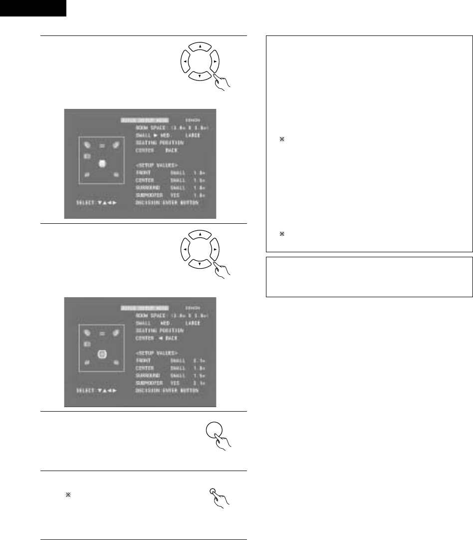
ENGLISH
32
9Use the •and ªcursor buttons
to select “ROOM SPACE”, then
use the 0and 1cursor buttons
to set the size of the room.
•The set size is displayed in
yellow.
Remote control unit
10 Use the •and ªcursor buttons
to select “SEATING POSITION”,
then use the 0and 1cursor
buttons to set the position.
•The set position is displayed in
yellow.
Remote control unit
11 Press the ENTER button to end the
settings.
•The screen in step 2 reappears.
ENTER
Remote control unit
12 Press the SETUP button to quit the
setup mode.
The setup mode can also be quit by
using use the •and ªcursor buttons
at the setup screen to select “EXIT
SETUP” then pressing the ENTER
button.
SETUP
Remote control unit
About the speaker system settings
B2CH VIRTUAL
Select this when only using with the two speakers for the front
channels.
B2CH VIRTUAL & SW
Select this when using two speakers for the front channels and
a subwoofer with built-in amplifier.
•Settings
Front : Small
Subwoofer : Yes
Subwoofer frequency : 150 Hz
Set the front speakers and subwoofer at equal distances.
B5.1CH SURROUND
Select this when using two speakers for the front channels, a
center speaker, two speakers for the surround channels and a
subwoofer with built-in amplifier.
•Settings
Front : Small 2.7m (9ft)
Center : Small 2.4m (8ft)
Surround : Small 2.1m (7ft)
Subwoofer : Yes 2.7m (9ft)
Subwoofer frequency : 150 Hz
The room setting is set to “MED.”, the listening position to
“BACK”.
NOTE:
•The speaker system is set to “2CH VIRTUAL” upon shipment
from the factory. If using speakers for the two front channels and
a subwoofer, change the setting to “2CH VIRTUAL & SW”.
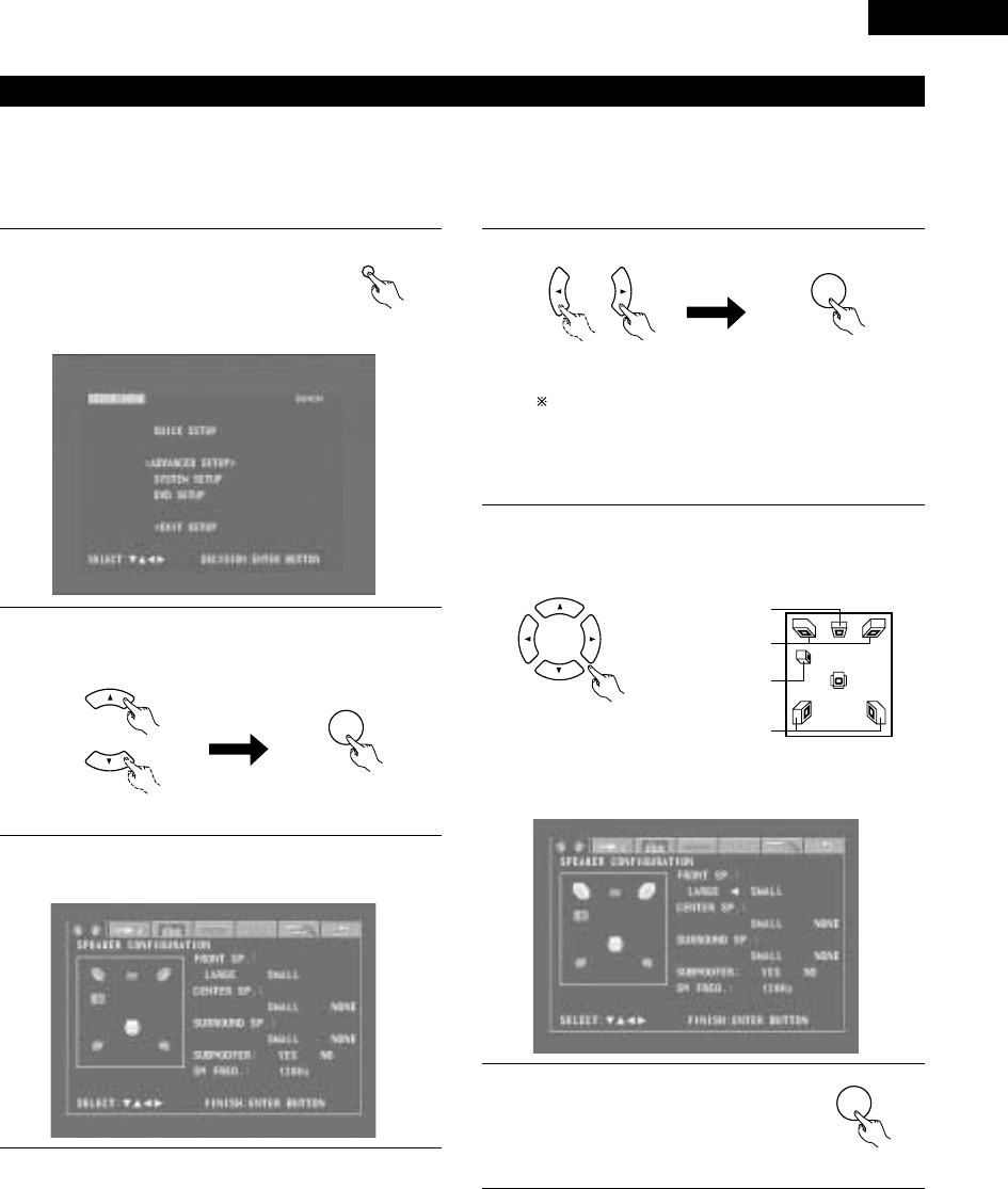
33
ENGLISH
(3) Detailed system setup (changing the system settings)
•The quick system settings and original settings set upon shipment from the factory are changed using the system setting changing menu. The
settings are stored in the memory until they are changed the next time, and remain valid even when the power is turned off.
[1] Speaker settings (type of speaker and whether or not the speaker is connected)
•The output component of the different channels and properties are adjusted automatically according to the combination of speakers actually
used.
1Press the SETUP button to display the
setup screen.
SETUP
Remote control unit
2Use the •and ªcursor buttons to select “SYSTEM SETUP”
under “<ADVANCED SETUP>”, then press the ENTER
button.
ENTER
Remote control unit Remote control unit
3At the system setting changing menu, use the 0and 1
cursor buttons to select the “SPEAKER CONFIGURATION”
tag icon, then press the ENTER button.
3
When the cursor is at a tag icon on the system setting
changing menu screen, the settings screen can also be
selected by pressing the ªcursor button. You can return to
the tag icon by pressing the •cursor button.
•The speaker settings screen in step 4 appears.
ENTER
Remote control unit Remote control unit
4Use the •, ª, 0and 1cursor buttons to select whether or
not the various speakers are connected, their size and other
parameters.
Remote control unit
•The item currently being set is displayed in yellow, and the
setting values for other items are displayed in green.
CENTER SPEAKER
FRONT SPEAKERS
SUB WOOFER
SURROUND
SPEAKERS
5Press the ENTER button to enter the
settings.
•The next screen in the system setting
changing menu appears.
ENTER
Remote control unit

ENGLISH
34
NOTE:
•Select the speaker size not by the physical size of the speaker
but by the speaker’s capacity to reproduce low frequencies of
100 Hz or less. If you do not know, determine the best setting by
comparing the sound when the setting is set to “Small” and
“Large”, keeping the volume low enough to prevent damage to
the speaker.
NOTE:
•Select “Large” or “Small” not according to the actual size of the
speaker but according to the speaker’s capacity for playing low
frequency (approximately 100 Hz and below) signals. If you do
not know, try comparing the sound at both settings (setting the
volume to a level low enough so as not to damage the speakers)
to determine the proper setting.
Parameters
Large…… Select this when using speakers that can fully reproduce
low sounds of below 100 Hz.
Small…… Select this when using speakers that do not provide
sufficient volume for playing low frequencies of 100 Hz
and less. When this setting is made, frequencies below
the frequency set at the subwoofer frequency setting
are assigned to the subwoofer.
None…… Select this when no speakers are installed.
Yes/No…. Select “Yes” when a subwoofer is installed, “No” when
a subwoofer is not installed.
If the subwoofer has sufficient low frequency playback capacity,
good sound can be achieved even when “Small” is set for the
front, center and surround speakers.
For the majority of speaker system configurations, using the
SMALL setting for all five main speakers and Subwoofer On
with a connected subwoofer will yield the best results.
Subwoofer (SW FREQ.) frequency
•For the subwoofer frequency at the speaker setting screen, set
the bass crossover frequency for playback from the subwoofer.
•Select “80 Hz”, “120 Hz”, “150 Hz” or “180 Hz” (-6 dB for
each). Bass sound below these frequencies is played from the
subwoofer.
(This is set to “150 Hz” by factory default.)
Assignment of low frequencies
•In the Dolby Digital, Dolby Pro Logic II, DTS, and virtual surround
modes, the low frequency signals for channels whose speaker
settings are set to “Small” are assigned to the subwoofer. The
low frequencies of channels set to “Large” are played from
those channels.
(If set to “120 Hz”, channels set to “Small” play sounds of 120
Hz and greater, while bass frequencies of under 120 Hz are
played from the subwoofer.)
•In surround modes other than the ones listed above, low
frequencies below the frequency set at the subwoofer frequency
setting are played from the subwoofer regardless of whether the
speakers are set to “Large” or “Small”.
•Set the subwoofer frequency according to the low frequency
playback abilities of your speakers and subwoofer.
Subwoofer mode
•The subwoofer mode setting is only valid when “LARGE” is set
for the front speakers and “YES” is set for the subwoofer in the
“SPEAKER CONFIGURATION” settings.
•When the “LFE+MAIN” playback mode is selected, the low
frequency signal range of channels set to “LARGE” are produced
simultaneously from those channels and the subwoofer channel.
In this playback mode, the low frequency range expand more
uniformly through the room, but depending on the size and shape
of the room, interference may result in a decrease of the actual
volume of the low frequency range.
•Selection of the “LFE ” play mode will play the low frequency
signal range of the channel selected with “LARGE” from that
channel only. Therefore, the low frequency signal range that are
played from the subwoofer channel are only the low frequency
signal range of LFE (only during Dolby Digital or DTS signal
playback) and the channel specified as “SMALL” in the setup
menu.
•Select the play mode that provides bass reproduction with body.
•When the subwoofer is set to “YES”, bass sound is output from
the subwoofer regardless of the subwoofer mode setting in
surround modes other than Dolby/DTS.

35
ENGLISH
[2] Delay time (distance setting)
•Input the distances from the listening position and the various speakers to set the surround delay time.
•Upon shipment from the factory default the delay time is set to the default values in step 3 below.
Preparation:
Measure the distance from the listening position to the various speakers.
FRFL
SRSL
Center
L1: Distance between center speaker
and listening position
L2: Distance between front speakers
and listening position
L3: Distance between surround
speakers and listening position
Listening position
1
2
If you are not at the system setting changing menu screen,
read step 1 and 2 on page 33.
At the system setting changing menu screen, use the 0and
1cursor buttons to select “DELAY TIME”, then press the
ENTER button.
•The delay time setting screen appears.
ENTER
Remote control unit Remote control unit
3At “Default”, select “Yes” to set the delay times for the
different speakers to the default values.
•The unit for the distance can be switched between “m”
(meters) and “ft” (feet) using the 0and 1cursor buttons.
If you do not want to change the unit, press the ªcursor
button to proceed to the next step.
BYes: The values are set to the defaults.
BNo: The current settings are retained.
4Use the •and ªcursor buttons to select the speaker, then
use the 0and 1cursor buttons to set the distance between
the speaker and the listening position.
•The distance changes by 0.1 meters (or 1 foot when the
unit is set to feet) each time the 0and 1cursor button is
pressed. Select the value closest to the measured
distance.
5Press the ENTER button to enter the
settings.
•The next screen in the system setting
changing menu appears.
ENTER
Make sure the difference in the distances set for the
various speakers is no greater than 3.0 meters (10 feet).
If an inappropriate distance is set, “CAUTION: OUT OF
SETTING RANGE” is displayed. Change the position of the
speaker and make the setting over.
Remote control unit

ENGLISH
36
[3] Adjusting the channel level
•Adjust so that the playback levels of the different channels are equal.
•Make this adjustment by listening to the test tones output from the speakers at the listening position.
•By factory default all the levels of all the channels are set to 0 dB.
•This adjustment can also be made directly from the remote control unit. (CH SELECT Button)
1If you are not at the system setting changing menu screen,
read step 1 and 2 on page 33.
2At the system setting changing menu screen, use the 0and
1cursor buttons to select “Channel Level”, then press the
ENTER button.
•The channel level adjustment screen appears.
3Use the 0and 1cursor buttons to
select “Auto” or “Manual” for the
“Test Tone” mode.
•The selected setting is displayed
in yellow.
BAuto: Adjust the levels listening to test tones
automatically output from the different speakers.
BManual: Select the speakers from which the test tones are
output when adjusting the levels.
Detailed settings can be made when this is set to
“Manual” first.
ENTER
Remote control unit Remote control unit
Remote control unit
4When “Yes” is selected at “Level Clear”, the level settings
for all the speakers are set to 0 dB.
BYes: The level settings for all the speakers are set to 0 dB.
BNo: The currently set level settings are retained.
5Adjust the channel levels in the test tone mode.
Use the •and ªcursor buttons to select the “Test Tone
Start” mode, then use the 0cursor button to select “Yes”.
The test tone is output.
Use the MASTER VOLUME control on the main unit or the
VOLUME buttons on the remote control unit to adjust the
volume of the test tone to a level at which it is easy to
make this adjustment.
6qWhen “Auto” is selected at “Test Tone”:
•Test tones are automatically output from the speakers at
intervals of 4 seconds for two of the cycles shown below,
then at intervals of 2 seconds from the third cycle on.
Use the 0and 1cursor buttons to adjust the channel levels
so that the volume of the test tones output from the different
speakers sounds the same.
•The level changes in units of 1 dB each time the 0and 1
cursor button is pressed.
The level can be adjusted in the range –12 dB to +12 dB.
Front left Center Front right
Surround rightSurround left Subwoofer
wWhen “Manual” is selected at “Test Tone”:
Use the •and ªcursor buttons to select the speaker from
which the test tone is to be output, then use the 0and 1
cursor buttons to adjust the channel levels so that the volume
of the test tones output from the different speakers sounds
the same.
•The level changes in units of 1 dB each time the 0and 1
cursor button is pressed.
The level can be adjusted in the range –12 dB to +12 dB.

37
ENGLISH
7Press the ENTER button to enter the
settings.
•The next screen in the system setting
changing menu appears.
ENTER
Remote control unit
To cancel the settings after the adjustments have been made
Display the channel level adjustment screen, then use the •, ª, 0
and 1cursor buttons to select “Level Clear” and select “Yes”.
The level settings for all the speakers are set to 0 dB.
NOTE:
When the channel levels are adjusted at the channel level settings,
the adjusted values are applied to all playback modes.
[5] DVD Auto Power Off setting
•The ADV-M71 is equipped with a function for automatically setting
the power to the standby mode if no operation is performed for 30
minutes when the function is set to DVD. Here set whether to use
this function or not.
•By factory default this is set to “No”.
1If you are not at the system setting changing menu screen,
read step 1 and 2 on page 33.
2At the system setting changing menu screen, use the 0and
1cursor buttons to select “DVD AUTO POWER OFF”, then
press the ENTER button.
•The DVD auto power off setting screen appears.
ENTER
Remote control unit Remote control unit
ENTER
Remote control unit Remote control unit
3Use the 0and 1cursor buttons to select the “Auto Power
Off” mode.
BYes: The function for automatically turning the power off
when the function is set to DVD is activated.
BNo: The auto power off function is not activated.
[4] Setting the AV1 video output (DVD only)
•To select whether composite video signals or S video signals or
RGB signals will be output from the AV1 SCART terminals.
•The factory default setting is “VIDEO”.
1
2
If you are not at the system setting changing menu screen,
read step 1 and 2 on page 33.
At the “SYSTEM SETUP MENU” screen, select “AV1 VIDEO
OUTPUT” and press the ENTER button.
•Switch to the “AV1 VIDEO OUT” screen.
3
4
Select “VIDEO OUTPUT”.
•VIDEO: Composite video signals will be output.
•S-VIDEO: S video signals will be output.
•RGB: RGB signals will be output.
Press the ENTER button to enter the
settings.
•The next screen in the system setting
changing menu appears.
ENTER
Remote control unit
4Press the ENTER button to enter the
settings.
•The next screen in the system setting
changing menu appears.
ENTER
Remote control unit
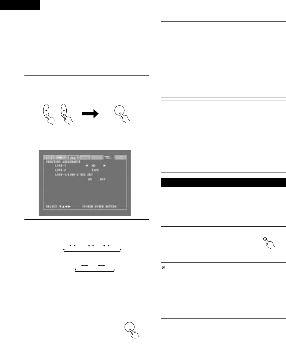
ENGLISH
38
4Press the ENTER button to enter the
settings.
•The next screen in the system setting
changing menu appears.
ENTER
Remote control unit
Input function settings
•LINE-1 and LINE-2 can be set as described below.
LINE-1 : “MD”, “CD-R”, “MD/CD-R” or “AUX” can be
selected.
(“MD/CD-R” can only be set when a system MD
recorder, cassette deck and CD recorder are all
connected and system operations are being used.)
LINE-2 : This can be set to “TAPE”, “MD”, “AUX” or “D.AUX”.
(Set “D.AUX” to use the D.AUX digital input in
combination with the LINE-2 analog input.)
•The setting for LINE-1 has priority. Once a function is set for
LINE-1, it is not possible to set the same function for LINE-2. (For
example, if “MD” is selected for LINE-1, “MD” is no longer
offered as one of the choices for LINE-2.)
LINE-1/LINE-2 analog recording output setting
•Normally set this to “On”.
•With the DVD or D.AUX exclusive digital input function, set this
to “Off” if noise is generated when playing sources with high bit
rates in the Dolby Virtual Speaker mode.
•This setting is only valid in the Dolby Virtual Speaker mode for the
DVD or D.AUX exclusive digital input function. (In surround
modes other than the Dolby Virtual Speaker mode and with other
input functions, analog recording signals are output, regardless of
this setting.)
•Analog recording is not possible when this is set to “Off”. To
record, use a mode other than the Dolby Virtual Speaker mode
(stereo, for example).
(4) After changing the system settings
•This completes the procedure for changing the system settings.
Once the speaker settings, delay times and channel levels have
been set, there is no need to change the settings again unless the
connected AV components or speakers are changed or the
speakers are moved to different positions.
•DVD auto power off and function settings as necessary.
1At the system setting changing menu
screen, press the SETUP button.
•The new settings are entered and the
on-screen display turns off.
SETUP
Remote control unit
The setup procedure can be quit at any point by pressing this
button.
NOTE:
•When system settings have been changed with the system
setting changing menu and a speaker system is selected with
the quick system settings, the speaker settings and delay time
settings are changed to the values preset for the quick system
settings.
3Use the •and ªcursor buttons to select the item to be set,
then use the 0and 1cursor buttons to make the settings.
BLINE-1 Function name selection (“MD” by default)
MD
CD-R
AUX MD/CD-R
BLINE-2 Function name selection (“TAPE” by default)
TAPE D.AUXAUX
BLINE-1/LINE-2 REC OUT
: Set whether to turn the recording output during playback in
the Dolby Virtual Speaker mode when the function set to
DVD or the D.AUX exclusive digital input on or off.
On : The signals are output in stereo. (Factory default)
Off : The signals are not output. (Recording is not
possible.)
[6] Function settings
•Set the LINE-1 and LINE-2 function names and turn the analog
recording output (REC OUT) on or off.
•When used in combination with the D-M31 series, set according to
the components being used and make system connections for
convenient system functions.
•It is also possible to assign the D.AUX digital input to LINE-2.
1If you are not at the system setting changing menu screen,
read step 1 and 2 on page 33.
2At the system setting changing menu screen, use the 0and
1cursor buttons to select “FUNCTION ASSIGNMENT”, then
press the ENTER button.
•The input function setting screen appears.
ENTER
Remote control unit Remote control unit

39
ENGLISH
B
BAND
PHONES
VOLUME
ON / STANDBY
DVD SURROUND RECEIVER ADV-M71
TONE/SDB
FUNCTION
MENU/SET +
-
SURROUND/SELECT
PUSH
-
PARAM.
2
+
-
+
-
RC-966
A / V
3
A-B REPEAT
SEARCH MODE
ONOFF
REPEAT RANDOM
CLEAR ZOOMSLIDE MODE
PROG/ DIRECT
MEMO BANDMODE
STAT US
RETURN
ANGLE AUDIO
SUB TITLE
SETUP TONE /SDB
FUNCTIONSURROUNDINPUT MODETEST TONE
DVD
TUNER
CH
3
-
+
21
654
987
0/10
CALL
ENTER
MUTING
+10
DISPLAY MENU
TOP MENU
SYSTEM MD
CDR TAPE
TUNER TV / VCR
SURROUND
PARAMETER
CH SELECT
VCR
NTSC/PAL
SLEEP
ENTER EDIT/MENUCHARAC.
REC
TIMETITLE
TUNING /
TV VOL
TV CH TV CH
TUNERDVD
MD/ LINE-1 TAPE/ LINE-2
AUTO DECODE
VIRTUALDIRECT
5CH STEREO
STEREO
D.AUX
-
+
VCR CH
IN/SURR.
IN/SURR.
DVD
T VTV INSOURCE
9
8
21
76
+
-
CD SRS
RTCT
PTYRDS
2
(1) Before Operating
11 PLAY BACK
1Refer to “CONNECTIONS” (pages 8 to 14) and check that all
connections are correct.
2Turn on the power.
Press the POWER
button.
When pressed, the power turns on and the display lights. The
sound is muted for several seconds, after which the unit
operates normally. When pressed again, the power turns off,
the standby mode is set and the display turns off.
Whenever the ON/STANDBY button is in the STANDBY state,
the apparatus is still connected on AC line voltage. Please be
sure to unplug the cord when you leave home for, say, a
vacation.
ON / STANDBY
ON
Light
(green)
Main unit Remote control unit
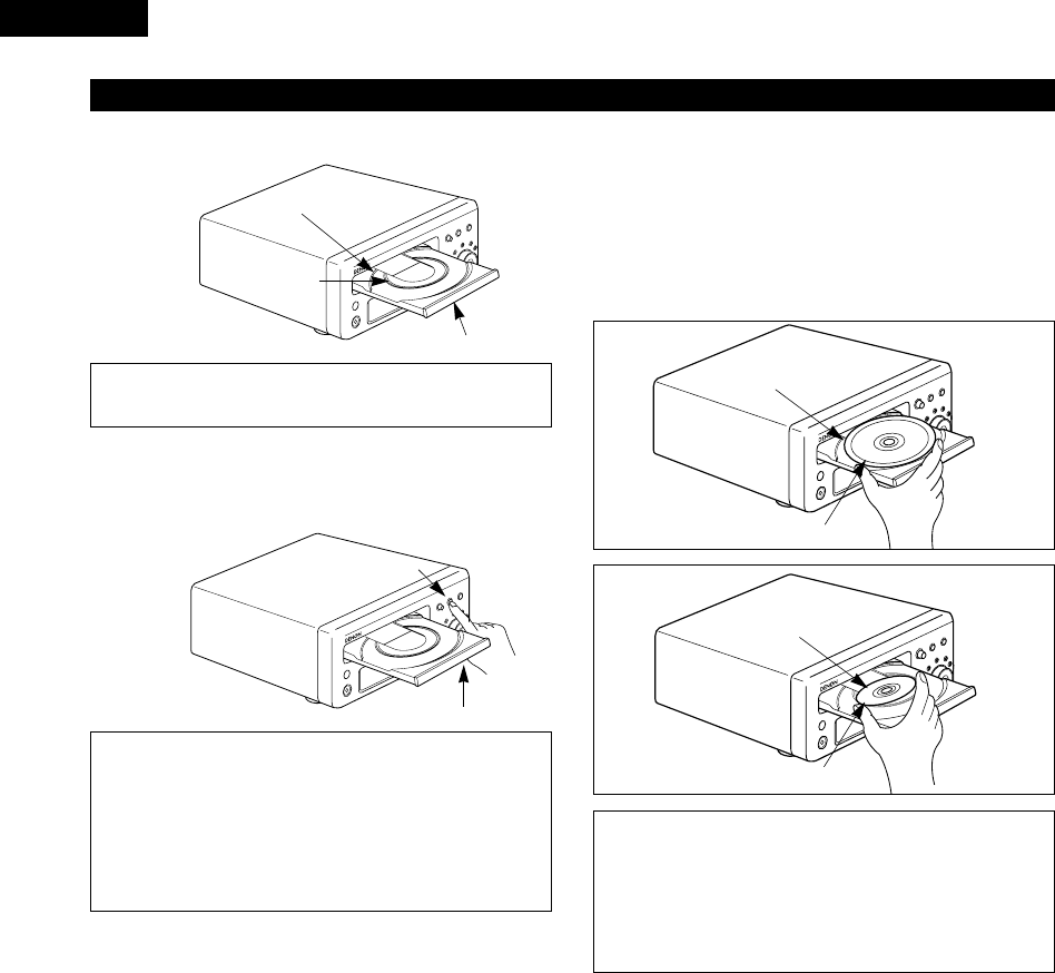
ENGLISH
40
2
Set discs in the disc tray with the labeled (printed) side facing up.
8 cm disc guide
Disc tray
NOTE:
•Do not move the this unit while a disc is playing. Doing so
may scratch the disc.
(1) Opening and Closing the Disc Tray
qTurn on the power.
wPress the OPEN/CLOSE button.
Disc tray
OPEN/CLOSE button
NOTES:
•Even when the power is in the standby mode, when the
OPEN/CLOSE button is pressed, the ADV-M71’s power turns
on and the disc tray operates. (Auto power on function)
•Even if the function is set to something other than DVD,
when the OPEN/CLOSE button is pressed, the function
switches to DVD and the disc tray operates. (Auto function
select function)
•Do not strike on the button with a pencil, etc.
12 cm disc guide
(2) Loading Discs
•Pick up the disc carefully so as not to touch the signal surface and
hold it with the labeled side facing up.
•With the disc tray fully open, set the disc in the disc tray.
•Set 12 cm discs in the outer tray guide (Figure 1), 8 cm discs in the
inner tray guide (Figure 2).
•Press the OPEN/CLOSE button. The disc is automatically loaded.
•The disc tray can also be closed automatically to load the disc by
pressing the PLAY button.
Figure 2
Inner disc tray
8 cm disc
NOTES:
•If a foreign object is caught in the disc tray during closing,
simply press the OPEN/CLOSE button again and the tray will
open.
•Do not press the disc tray in by hand when the power is off.
Doing so will damage it.
•Do not place foreign objects in the disc tray. Doing so will
damage it.
(2) Loading Disc
Figure 1
Outer disc tray
12 cm disc

41
ENGLISH
IMPORTANT SETUP INFORMATION
This set has the following presettings:
“DISC SETUP”, “OSD SETUP”, “VIDEO SETUP”, “AUDIO SETUP”,
“RATINGS”, and “OTHER SETUP”.
These presettings have been preset upon shipment from the factory.
If you wish to change them to suit your specific purposes, refer to
pages 94 to 106.
1
2
3
ON
ON / STANDBY
Turn on the power.
•Press the power button, the power indicator lights and the
power turns on.
Press the OPEN/CLOSE button to open the disc tray.
Set the disc in the disc tray.
4Press the OPEN/CLOSE button.
5Press the PLAY button.
•For many interactive DVDs and video CDs with playback
control, a menu screen appears. In this case use the
procedure in step 6 to select the desired item.
Interactive DVDs are DVDs including multiple angles,
stories, etc.
DVD
1
Main unit
Main unit
Main unit
Main unit
Remote control unit
Remote control unit
B
BAND
PHONES
VOLUME
ON / STANDBY
DVD SURROUND RECEIVER ADV-M71
TONE/SDB
FUNCTION
MENU/SET +
-
SURROUND/SELECT
PUSH
-
PARAM.
(3)-1 (3)-8
(3)-3 (3)-2,(3)-4
(3)-5
(4)-1
+
-
+
-
A / V
3
A-B REPEAT
SEARCH MODE
ONOFF
REPEAT RANDOM
CLEAR ZOOMSLIDE MODE
PROG/ DIRECT
MEMO BANDMODE
STAT US
SETUP TONE /SDB
FUNCTIONSURROUNDINPUT MODETEST TONE
DVD
TUNER
CH
3
-
+
21
654
987
0/10
CALL
ENTER
MUTING
+10
SYSTEM MD
CDR TAPE
TUNER TV / VCR
SURROUND
PARAMETER
CH SELECT
VCR
NTSC/PAL
SLEEP
ENTER EDIT/MENUCHARAC.
REC
TIMETITLE
TUNING /
TV VOL
TV CH TV CH
TUNERDVD
MD/ LINE-1 TAPE/ LINE-2
AUTO DECODE
VIRTUALDIRECT
5CH STEREO
STEREO
D.AUX
-
+
VCR CH
IN/SURR.
IN/SURR.
DVD
T VTV INSOURCE
9
8
21
76
+
-
CD SRS
RTCT
PTYRDS
(3)-1
(3)-6
(3)-7
(3)-8
(3)-5 (4)-1
Example: For DVDs with menu
screens
Example: For video CDs with
playback control
1. Opening
Banana
Strawberry
Pineapple
TOP MENU
Orange
Peach
Apple 2. 1st movement
3. 2nd movement
4. 3rd movement
5. Ending
(3) Playback
Light
(green)

ENGLISH
42
6Use the cursor buttons (•, ª, 0and 1) to select the desired
item.
•For some discs there is a second menu screen. If so, press
the 9button to display the next menu screen. (See the
disc’s jacket.)
The cursor buttons (•, ª, 0and 1) do not work for video
CDs. Use the number buttons to select the desired item.
Remote control unit
7Press the ENTER button.
•The desired item is selected and playback starts.
•You can return to the menu screen by pressing the TOP
MENU button while the DVD is playing, though this
depends on the disc.
•Press the RETURN button during playback of a video CD to
return to the menu screen.
Remote control unit
Example: When “Apple” is
selected
Apple
ENTER
Banana
Strawberry
Pineapple
TOP MENU
Orange
Peach
Apple
8Either turn the main unit’s main volume control or use the
main volume control buttons on the remote control unit to
adjust the volume.
M.VOLUME -20
The volume is shown
on the display.
+
-
VOLUME
Main unit Remote control unit
For detailed instructions on operations for the surround
modes and surround parameters, see “12 Operating the
Surround Functions” on pages 44 to 46.
•In the “AUTO” input mode, the signals of the disc being
played are identified, Dolby Digital, DTS or PCM decoding
is selected automatically and the disc is played.
•In the Dolby Virtual Speaker surround mode, the signals of
the disc being played are automatically decoded in Dolby
Digital or DTS then played in the Dolby Virtual Speaker
surround mode.
•In the “AUTO DECODE” surround mode when a 5.1-
channel speaker system is set, the signals of the disc being
played are identified and automatically decoded in Dolby
Digital, DTS or Auto Stereo and the disc is played.
NOTES:
•If appears on the TV screen while buttons are being
operated, that operation is not possible on the ADV-M71 or with
that disc.
•Set the disc in the disc guide.
•Only set one disc in the tray.
•The disc keeps turning while the menu screen is displayed on the
TV screen.
The resume play memory function only works for discs for
which the elapsed time is shown on the display during
playback.
1
2
BAND
During playback, press the STOP button on the main unit or
the remote control unit, playback stops and wall paper is
displayed.
<Resume play memory function (DVD only)>
•With the ADV-M71, when the STOP button is pressed, that
position is stored in the memory. At this time, “1” flashes
on the display. When the PLAY button is pressed after
pressing the STOP button, playback resumes from the
position at which it was stopped.The resume play memory
function is canceled if the disc tray is opened or the STOP
button is pressed a second time.
Auto power off function.
•The ADV-M71 is equipped with a function that
automatically switches the power to standby if no
operation is performed for 30 minutes while in the stop
mode with the function set to DVD.
•This function is set to off upon shipment from the
factory. If you wish to turn it on, set the “DVD AUTO
POWER OFF” setting to “YES” as described on page 37.
Main unit Remote control unit
(4) Stopping Playback
About the DVD standby function
When the ADV-M71’s function is set to DVD, the DVD
standby mode is set automatically if the disc remains in the
stop mode for approximately 10 minutes.
•In the DVD standby mode, the DVD section’s power is
off and output of the video signals is also off.
The ADV-M71’s display reads “DVD standby” at this
time.
•When in the DVD standby mode, the power of the
sections other than the DVD section is on and function
switching and other operations can be performed on the
main unit and remote control unit. When a DVD control
button (the play/pause and button open/close buttons on
the main unit, the play button on the remote control unit,
etc.) is operated, the DVD section’s power turns on
automatically and disc playback and opening/closing of
the disc holder can be performed.
NOTE:
•The DVD standby function only turns off the power of the DVD
section. It is different from the DVD auto power off function set
with the system settings in Setup in that the DVD section
remains functional.
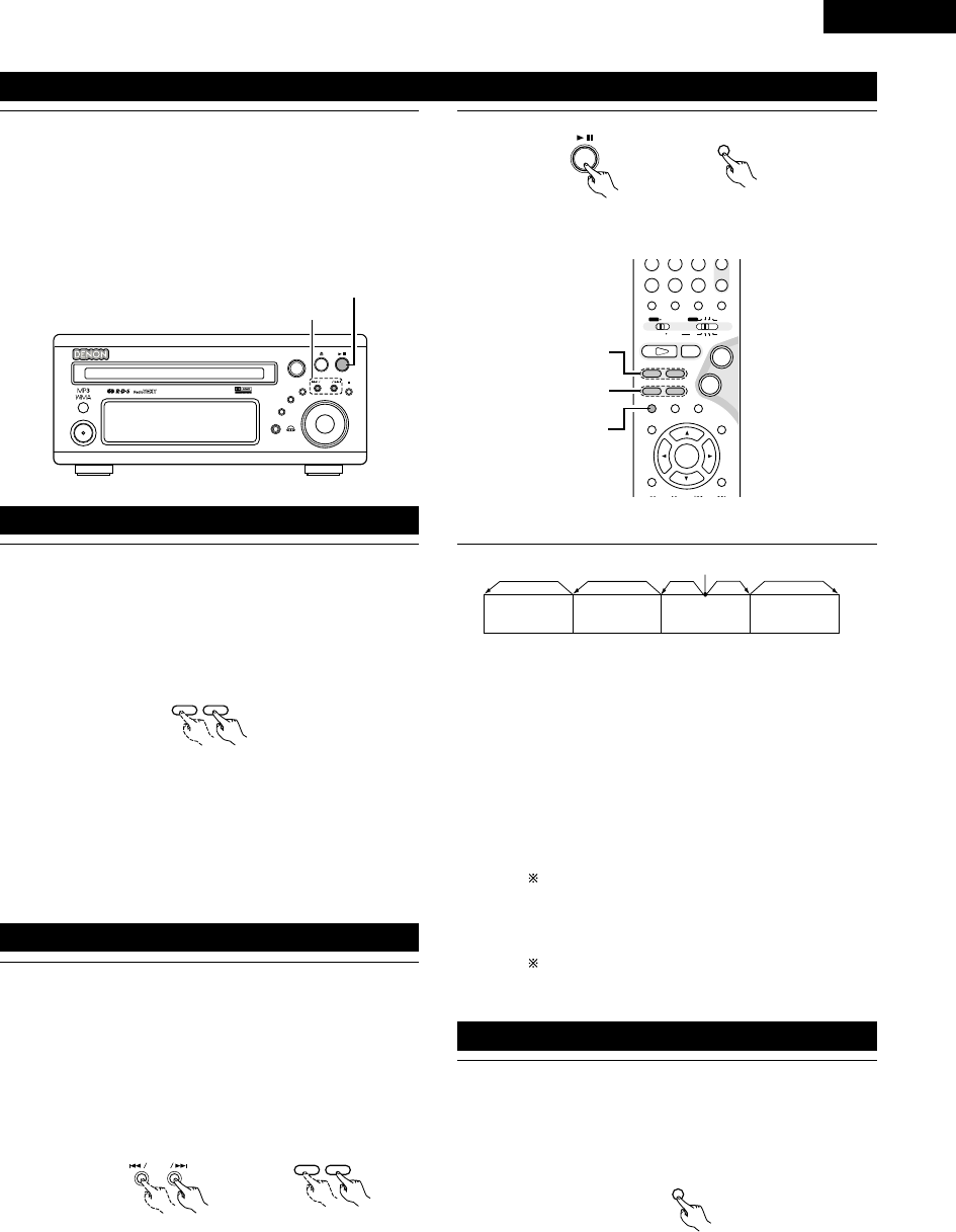
43
ENGLISH
1During playback, press the 13 button on the main unit or the
3button on the remote control unit.
•Press the PLAY button to resume normal playback.
3
Main unit Remote control unit
(5) Playing Still Pictures (Pausing)
B
BAND
PHONES
VOLUME
ON / STANDBY
DVD SURROUND RECEIVER ADV-M71
TONE/SDB
FUNCTION
MENU/SET +
-
SURROUND/SELECT
PUSH
-
PARAM.
(7)-1
(5)-1
+
-
A / V
3
STAT US
SETUP TONE /SDB
FUNCTIONSURROUNDINPUT MODETEST TONE
DVD
CH
987
0/10
CALL
ENTER
MUTING
+10
SYSTEM MD
CDR TAPE
TUNER TV / VCR
SURROUND
PARAMETER
CH SELECT
VIRTUALDIRECT STEREO
-
+
VCR CH
IN/SURR.
IN/SURR.
DVD
9
8
21
76
+
-
(5)-1,(8)-1
(6)-1,(9)-1
(7)-1
NOTE:
•In some cases the menu screen may reappear when one of
the 6/ 7buttons is pressed during menu playback on
a video CD.
1
76
During playback, press one of the 6/ 7buttons on the
remote control unit.
6: Reverse direction
7: Forward direction
•When pressed again, the search speed increases (DVD,
VIDEO CD in seven steps, CD in four steps).
•Press the PLAY button to resume normal playback.
Remote control unit
1During playback, press one of the skip buttons on the main
unit or the remote control unit.
8/ : Reverse direction (PREVIOUS)
9/ : Forward direction (NEXT)
•A number of chapters or tracks equal to the number of
times the button is pressed is skipped.
•When the skip back button is pressed once, the pickup
returns to the beginning of the currently playing chapter or
track.
(6) Forward / Reverse Searching
(7)
Skipping to the Beginning of Chapters or Tracks
+
-
9
8
Main unit Remote control unit
Playing position
Chapter/Track Chapter/Track Chapter/Track Chapter/Track
Reverse direction ,/Forward direction (direction of playback)
NOTE:
•In some cases the menu screen may reappear when one of
the 8/ 9buttons is pressed during menu playback
on a video CD.
Searching using the number buttons
qDuring playback, press the search mode button on the
remote control unit.
•The mode switches as shown below each time the
button is pressed:
For DVDs : Title ,/Chapter
For CDs and video CDs : Track (no switching)
The search mode set by pressing the search mode
button is stored in the memory until the power is
turned off.
wUse the number buttons on the remote control unit to
input the number of the title, chapter or track to be played.
Some DVDs or video CDs may be designed to operate
in special ways and will not operate as described here.
1During playback, press the 3button on the remote control
unit.
•The picture moves forward one frame each time the button
is pressed.
•Press the PLAY button to resume normal playback.
(8)
Playing Frame by Frame (for DVDs and video CDs only)
3
Remote control unit

ENGLISH
44
1In the still mode, press one of the 6/ 7buttons on the
remote control unit.
6: Reverse direction
7: Forward direction
•When pressed again, the slow play speed increases.
(Four step) (Three step on video CDs)
•Press the PLAY button to resume normal playback.
(9)
Slow Playback (for DVDs and video CDs only)
76
Remote control unit
NOTE:
•Reverse slow play is not possible on video CDs.
B
BAND
PHONES
VOLUME
ON / STANDBY
DVD SURROUND RECEIVER ADV-M71
TONE/SDB
FUNCTION
MENU/SET +
-
SURROUND/SELECT
PUSH
-
PARAM.
5
13
+
-
-
A / V
3
STAT US
SETUP TONE /SDB
FUNCTIONSURROUNDINPUT MODETEST TONE
DVD
TUNER
CH
654
987
0/10
CALL
ENTER
MUTING
+10
SYSTEM MD
CDR TAPE
TUNER TV / VCR
SURROUND
AUTO DECODE
VIRTUALDIRECT
5CH STEREO
STEREO
IN/SURR.
IN/SURR.
DVD
9
8
21
76
+
-
5
23
1
12
OPERATING THE SURROUND FUNCTIONS
(1) Input mode setting
1Press the FUNCTION button to select the input function to be
played.
FUNCTION
FUNCTION
•The function switches as shown below.
•Factory default (LINE 1) = MD, (LINE 2) = TAPE
DVD TUNER (LINE2) D.AUX
(LINE1)
Main unit Remote control unit
2When DVD, D.AUX was selected as the input function, press
the remote control unit’s INPUT MODE button to select the
input mode.
INPUT MODE
•“ANALOG” cannot be selected when DVD or D.AUX was
selected as the input function.
•“ANALOG” can be selected when “LINE-2” is set to
“D.AUX” at “FUNCTION ASSIGNMENT” under “SYSTEM
SETUP” in the detailed settings.
AUTO PCM DTS ANALOG
Remote control unit
Input mode selection function
•The input mode can be selected when the input function is
set to DVD, D.AUX.
•Different input modes can be selected for each input
function. The selected input mode is stored in the memory
for the individual input functions.
•When the input function is set to something other than the
above, “ANALOG ONLY” is displayed and the input mode
cannot be selected.
qAUTO (auto mode)
In this mode, the type of signal being input to the digital
and analog input terminals is detected and the program in
the set’s surround decoder is switched automatically to
play the signals for the selected input function.
The presence or absence of digital signals is detected, the
signals input to the digital input are identified and decoding
and playback are performed automatically in DTS, Dolby
Digital or PCM (2 channel stereo) format.
If no digital signal (LINE1) = MD is being input, the analog
input jacks are selected.
Use this mode to play Dolby Digital signals.
wPCM (exclusive PCM signal playback mode)
Decoding and playback are only performed when PCM
signals are being input.
eDTS (exclusive DTS signal playback mode)
Decoding and playback are only performed when DTS
signals are being input.
rANALOG (exclusive analog audio signal playback mode)
The signals input to the analog input jacks are played.
(This cannot be selected in the DVD mode.)
The input mode automatically switches to “AUTO” if you
switch the input function to DVD from anything other than
DVD.

45
ENGLISH
3Either turn the SURROUND/SELECT dial or press the
SURROUND button on the remote control unit to select the
surround mode.
SURROUND/ SELECT
PUSH
-
PARAM.
SURROUND
Main unit Remote control unit
•The function switches as shown below.
•The function only changes in the “Æ” direction when
operated from the remote control unit.
DOLBY VS STEREO *AUTO DECODE
*5CH STEREO *MONO MOVIE ROCK ARENA
DIRECT
JAZZ CLUB
DOLBY VS
VIDEO GAME *MATRIX
•The modes marked “*” can be selected when “5.1-
channel surround” is selected in the quick system setup.
4Start playback on the selected component.
•For operating instructions, refer to the component’s
manual.
•The volume can be adjusted within the range –60 to 0 to
+18 dB. Note that depending on the input signal, surround
mode, speaker settings and channel level setting, it may
not be possible to adjust the volume up to +18 dB.
5Either turn the MASTER VOLUME dial on the main unit or
use the VOLUME buttons on the remote control unit to
adjust the volume.
M.VOLUME -20
VOLUME
Main unit
+
-
Remote control unit
The volume level is displayed
on the display. •“DIG” lights when digital signals are input properly. If “DIG” is
flashing, check whether the connections are proper and whether
the input component’s power is on.
Input mode display
•In the AUTO mode
•In the DIGITAL PCM mode
•In the DIGITAL DTS mode
•In the ANALOG mode
One of these lights, depending on
the input signal.
Lit
Input signal display
•DOLBY DIGITAL
•DTS
•PCM
Input mode when playing CD sources
•When playing CDs containing recordings of live concerts, etc., in
the “AUTO” mode, the sound may be slightly broken at the
beginning. If this happens, switch to the “PCM” mode.
Input mode when playing DTS sources
•If DTS-compatible CDs are played in the “PCM” mode, noise is
output because DTS playback is not possible.
To play a DTS-compatible source, be sure to set the input mode
to “AUTO” or “DTS”.
•Noise may be generated at the beginning of playback and while
searching during DTS playback in the AUTO mode. If so, play in
the DTS mode.
MENU/SET
Main unit
SURROUND/ SELECT
PUSH
-
PARAM.
Main unit
STAT U S
Remote control unit
2To check the currently playing program source, etc.
Press the MENU/SET button. Display “STATUS” then turn
the SURROUND/SELECT control.
To perform this operation on the remote control unit, press
the STATUS button.
The current program source and surround settings are shown
on the display each time the button is pressed or turned.
(When the function is set to DVD, the information is also
displayed on the TV screen.)

ENGLISH
46
B
BAND
PHONES
VOLUME
ON / STANDBY
DVD SURROUND RECEIVER ADV-M71
TONE/SDB
FUNCTION
MENU/SET +
-
SURROUND/SELECT
PUSH
-
PARAM.
2
1
3
STAT US
RETURN
SETUP TONE /SDB
ENTER
MUTING
DISPLAY MENU
TOP MENU
SURROUND
PARAMETER
CH SELECT
-
+
VCR CH
1
2
A / V
3
STAT US
RETURN
ANGLE AUDIO
SUB TITLE
SETUP TONE /SDB
FUNCTIONSURROUNDINPUT MODETEST TONE
DVD
ENTER
MUTING
DISPLAY MENU
TOP MENU
SYSTEM MD
CDR TAPE
TUNER TV / VCR
SURROUND
PARAMETER
CH SELECT
-
+
VCR CH
IN/SURR.
IN/SURR.
DVD
9
8
21
76
+
-
1
(2) After starting playback
[1] Adjusting the sound quality (TONE/SDB)
The TONE/SDB function will not work in the direct mode.
[2] Turning the sound off temporarily (MUTING)
1Press the TONE/SDB button.
•The tone switches as follows each time the TONE/SDB
button is pressed.
DEFEAT
•The signals do not pass through the SDB, bass and treble
adjustment circuits, providing higher quality sound.
SDB
•Either turn the FUNCTION / SELECT dial or use the ( 0,
1) cursor buttons to select “ON” or “OFF”.
BASS, TREBLE
•To increase the bass or treble: Turn the control clockwise or
press the cursor button. (The bass or treble sound can be
increased to up to +10 dB in steps of 2 dB.)
•To decrease the bass or treble: Turn the control clockwise
or press the cursor button. (The bass or treble sound can be
decreased to up to –10 dB in steps of 2 dB.)
When TONE/SDB is displayed, the item can be switched
using the •and ªbuttons on the remote control unit.
If no operation is performed within 4 seconds, the display
switches back to what was previously displayed.
TONE/SDB
TONE /SDB
1Use this to turn off the audio output temporarily.
Press the MUTING button.
Cancelling MUTING mode.
Press the MUTING button again.
MUTING
DEFEAT SDB
(ON/OFF) BASS TREBLE
Main unit Remote control unit
Remote control unit
2With the name of the volume to be adjusted selected, turn
the SURROUND/SELECT knob or cursor button ( 0, 1) to
adjust the level.
SURROUND/ SELECT
PUSH
-
PARAM.
Main unit Remote control unit
NOTES:
•The mute mode is canceled when the main unit’s main volume
control or one of the main volume control buttons on the remote
control unit is operated.
•The setting is canceled if the set’s power is turned off.

47
ENGLISH
Surround
This unit is equipped with a digital signal processing circuit that lets you play program sources in the surround mode to achieve the same sense
of presence as in a movie theater.
Dolby Surround
(1) Dolby Digital (Dolby Surround AC-3)
Dolby Digital is the multi-channel digital signal format developed by Dolby Laboratories.
Dolby Digital consists of up to “5.1” channels - front left, front right, center, surround left, surround right, and an additional channel exclusively
reserved for additional deep bass sound effects (the Low Frequency Effects – LFE – channel, also called the “.1” channel, containing bass
frequencies of up to 120 Hz).
Unlike the analog Dolby Pro Logic format, Dolby Digital’s main channels can all contain full range sound information, from the lowest bass, up
to the highest frequencies – 22 kHz. The signals within each channel are distinct from the others, allowing pinpoint sound imaging, and Dolby
Digital offers tremendous dynamic range from the most powerful sound effects to the quietest, softest sounds, free from noise and distortion.
2Dolby Digital and Dolby Pro Logic
Comparison of home surround systems
No. recorded channels (elements)
No. playback channels
Playback channels (max.)
Audio processing
High frequency playback limit of surround
channel
Dolby Digital
5.1 ch
5.1 ch
L, R, C, SL, SR, SW
Digital discrete processing Dolby Digital (AC-3) encoding/decoding
20 kHz
Dolby Pro Logic
2 ch
4 ch
L, R, C, S (SW - recommended)
Analog matrix processing Dolby Surround
7 kHz
2Dolby Digital compatible media and playback methods
Marks indicating Dolby Digital compatibility: and .
The following are general examples. Also refer to the player’s operating instructions.
Media
LD (VDP)
DVD
Others
(satellite broadcasts, CATV, etc.)
Dolby Digital output jacks
Coaxial Dolby Digital RF output jack
1
Optical or coaxial digital output
(same as for PCM)
2
Optical or coaxial digital output
(same as for PCM)
Playback method (reference page)
Set the input mode to “AUTO”.
(Page 44, 45)
Set the input mode to “AUTO”.
(Page 44, 45)
Set the input mode to “AUTO”.
(Page 44, 45)
1 Use a commercially available adapter to connect Dolby Digital RF (AC-3RF) output signals to the digital input terminals. (Refer to the
adapter’s operating instructions.)
Please refer to the instruction manual of the adapter when making connection.
2 To play in Dolby Digital Surround on the ADV-M71, set “DVD SUTUP” – “AUDIO SETUP” – “DIGITAL OUT” to “Normal” in the setup.
(The factory default is “Normal”.)
(2) Dolby Pro Logic II
•Dolby Pro Logic II is a new multi-channel playback format developed by Dolby Laboratories using feedback logic steering technology and
offering improvements over conventional Dolby Pro Logic circuits.
•Dolby Pro Logic II can be used to decode not only sources recorded in Dolby Surround ( ) but also regular stereo sources into five channels
(front left, front right, center, surround left and surround right) to achieve surround sound.
•Whereas with conventional Dolby Pro Logic the surround channel playback frequency band was limited, Dolby Pro Logic II offers a wider
band range (20 Hz to 20 kHz or greater). In addition, the surround channels were monaural (the surround left and right channels were the
same) with previous Dolby Pro Logic, but Dolby Pro Logic II they are played as stereo signals.
•
Various parameters can be set according to the type of source and the contents, so it is possible to achieve optimum decoding (see page 60).
Sources recorded in Dolby Surround
These are sources in which three or more channels of surround have been recorded as two channels of signals using Dolby Surround
encoding technology.
Dolby Surround is used for the sound tracks of movies recorded on DVDs, LDs and video cassettes to be played on stereo VCRs, as well
as for the stereo broadcast signals of FM radio, TV, satellite broadcasts and cable TV.
Decoding these signals with Dolby Pro Logic makes it possible to achieve multi-channel surround playback. The signals can also be played
on ordinary stereo equipment, in which case they provide normal stereo sound.
There are two types of DVD Dolby surround recording signals.
q2-channel PCM stereo signals
w2-channel Dolby Digital signals
Regardless of the signal being played, when the 2-channel decode mode is set to the “Pro Logic II” mode in the “AUTO DECODE” mode,
the surround mode is automatically set to “Dolby Pro Logic II”.
13
DOLBY / DTS SURROUND

ENGLISH
48
2Sources recorded in Dolby Surround are indicated with the logo mark shown below.
Dolby Surround support mark:
Manufactured under license from Dolby Laboratories.
“Dolby”, “Pro Logic” and the double-D symbol are trademarks of Dolby Laboratories.
DTS Digital Surround
Digital Theater Surround (also called simply DTS) is a multi-channel digital signal format developed by Digital Theater Systems.
DTS offers the same “5.1” playback channels as Dolby Digital (front left, front right and center, surround left and surround right) as well as the
stereo 2-channel mode. The signals for the different channels are fully independent, eliminating the risk of deterioration of sound quality due to
interference between signals, crosstalk, etc.
DTS features a relatively higher bit rate as compared to Dolby Digital (1234 kbps for CDs and LDs, 1536 kbps for DVDs) so it operates with a
relatively low compression rate. Because of this the amount of data is great, and when DTS playback is used in movie theaters, a separate CD-
ROM synchronized with the film is played.
With LDs and DVDs, there is of course no need for an extra disc; the pictures and sound can be recorded simultaneously on the same disc, so
the discs can be handled in the same way as discs with other formats.
Other media include CDs recorded in DTS. These are the same discs as conventional CDs (recorded in 2 channels) but include 5.1 channel
surround signals. They do not include images, but they do permit surround playback on the ADV-M71 and on CD players.DTS surround track
playback offers the same intricate, grand sound as in a movie theater, right in your own listening room.
2DTS compatible media and playback methods
Marks indicating DTS compatibility: and .
The following are general examples. Also refer to the player’s operating instructions.
Media
CD
LD (VDP)
DVD
DTS Digital output jacks
Optical or coaxial digital output
(same as for PCM) 2
Optical or coaxial digital output
(same as for PCM) 2
Optical or coaxial digital output
(same as for PCM) 3
Playback method (reference page)
Set the input mode to “AUTO” or “DTS” (page 44, 45).
Never set the mode to “ANALOG” or “PCM”. 1
Set the input mode to “AUTO” or “DTS” (page 44, 45).
Never set the mode to “ANALOG” or “PCM”. 1
Set the input mode to “AUTO” or “DTS” (page 44, 45).
1 DTS signals are recorded in the same way on CDs and LDs as PCM signals. Because of this, the un-decoded DTS signals are output as
random “hissy” noise from the CD or LD player’s analog outputs. If this noise is played with the amplifier set at a very high volume, it
may possibly cause damage to the speakers. To avoid this, be sure to switch the input mode to “AUTO” or “DTS” before playing CDs or
LDs recorded in DTS. Also, never switch the input mode to “ANALOG” or “PCM” during playback. The same is true when playing CDs
and LDs recorded in DTS on the ADV-M71 or on LD/DVD compatible players. With DVDs, the DTS signals are recorded with a special
recording method so there is no problem. For DVDs, the DTS signals are recorded in a special way so this problem does not occur.
2 The signals provided at the digital outputs of a CD or LD player may undergo some sort of internal signal processing (output level
adjustment, sampling frequency conversion, etc.). In this case the DTS-encoded signals may be processed erroneously, in which case they
cannot be decoded by this unit, or may only produce noise. Before playing DTS signals for the first time, turn down the master volume to
a low level, start playing the DTS disc, then check whether the DTS indicator on this unit (see page 45) lights before turning up the master
volume.
3 To play in DTS Digital Surround on the ADV-M71, set “DVD SETUP” — “AUDIO SETUP” — “DIGITAL OUT” to “Normal” in the setup.
(The factory default is “Normal”.)
“DTS” and “DTS Digital Surround” are registered trademarks of Digital Theater Systems, Inc.

49
ENGLISH
Dolby Virtual Speaker
Dolby Virtual Speaker technology uses proprietary technology of Dolby Laboratories to create a virtual surround sound field using only two
speakers for the front channels, allowing the user to experience sound as if surround speakers were actually being used.
2Features of Dolby Virtual Speaker sound
BAccurate surround sound field positioning
The virtual surround speakers are positioned at 105°to the left and 105°to the right.
BMulti-channel programs played according to the producer’s intentions
The sound of the different channels is played in the position set upon mixing. For example, sound set at the rear left is heard from the rear
left.
BStereo programs played in surround
The Dolby Pro Logic II circuit is used together with the Dolby Virtual Speaker circuitry to create a rich virtual surround sound field with stereo
programs as well.
BSelecting the listening mode
Two listening modes are provided: Reference and Wide.
Reference mode Wide mode
: 2 front channels
With the ADV-M71, playback in the Dolby Virtual Speaker mode is possible with other speaker configurations as well.
•3 speakers (2 front channels + center) : Reference/Wide modes
•4 speakers (2 front channels + 2 surround channels) : Wide mode
•5 speakers (2 front channels + center + 2 surround channels) : Wide mode
Dolby Headphone
Dolby Headphone is a 3D sound technology developed jointly by Dolby Laboratories and Lake Technology of Australia achieving surround sound
with regular headphones.
Normally when using headphones all the sounds are sounded in the head, making it uncomfortable to listen with headphones for long periods of
time. Dolby Headphone simulates speaker playback in a room and positions the sound sources to the front or the sides, outside of the head,
achieving a powerful sound similar to that of a movie theater or home theater. This technology is aimed mainly at multi-channel audio or video
equipment including Dolby Digital or Dolby Pro Logic Surround decoding functions and operates inside a high performance digital signal processing
chip (DSP).
The Dolby Headphone mode can be used not only with multi-channel sources but also with stereo programs.
: Virtual sound field created with the Dolby
Virtual Speaker mode
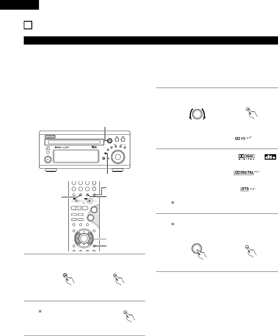
ENGLISH
50
(1) Playing in the Dolby Virtual Speaker mode
•The Dolby Virtual Speaker mode is a mode using 3D sound technology from Dolby Laboratories to achieve multi-channel surround sound using
only two speakers for the front channels.
•With two speakers for the front channels, one of two modes can be selected: Reference or Wide.
•The Dolby Virtual Speaker mode can be used not only with Dolby Digital and DTS multi-channel sources but also with 2-channel sources. With
2-channel sources, one of two 2-channel modes can be selected: Virtual 1 (Dolby Pro Logic II Cinema) and Virtual 2 (Dolby Pro Logic).
•With a multi-channel speaker configuration (for example 5.1 channels), the Dolby Virtual Speaker mode provides different effects according to
the speaker configuration.
14
SURROUND PLAYBACK
[1] Playing Dolby Digital and DTS surround sound (with digital
inputs only)
BApplicable sources
•Digital input (D.AUX functions, including DVD playback discs)
Dolby Digital multi-channel sources
DTS sources
B
BAND
PHONES
VOLUME
ON / STANDBY
DVD SURROUND RECEIVER ADV-M71
TONE/SDB
FUNCTION
MENU/SET +
-
SURROUND/SELECT
PUSH
-
PARAM.
1
3,5,6
+
-
A / V
3
STAT US
SETUP TONE /SDB
FUNCTIONSURROUNDINPUT MODETEST TONE
DVD
CH
987
0/10
CALL
ENTER
MUTING
+10
SYSTEM MD
CDR TAPE
TUNER TV / VCR
SURROUND
PARAMETER
CH SELECT
VIRTUALDIRECT STEREO
-
+
VCR CH
IN/SURR.
IN/SURR.
DVD
9
8
21
76
+
-
23
1
6
5
1Select the digital input function (DVD or D.AUX digital input).
FUNCTION
FUNCTION
Main unit Remote control unit
2Set the input mode to “AUTO”.
DTS sources can also be played with
the input mode set to “DTS”.
INPUT MODE
Remote control unit
•In the Dolby Virtual Speaker
mode, this indicator lights.
3Set the surround mode to “DOLBY VIRTUAL SPEAKER”.
SURROUND/ SELECT
PUSH
-
PARAM.
SURROUND
Main unit Remote control unit
Lit
4Play a program source including the or
mark.
•The Dolby Digital indicator lights
when playing Dolby Digital
sources.
Lit
•The DTS indicator lights when
playing DTS sources.
Lit
This switches automatically according to the format of the
playback source.
5Display the surround parameters for that source.
When the function is set to DVD, this is displayed on the
screen as well.
SURROUND/ SELECT
PUSH
-
PARAM.
SURROUND
PARAMETER
Main unit Remote control unit

51
ENGLISH
Surround parameters (1)
DOLBY VS (Dolby Virtual Speaker mode)
•REF (Reference mode)
This is the standard mode.
•WIDE (Wide mode)
This mode expands the front channel sound field.
D.COMP. (Dynamic range compression)
•This parameter adjusts the dynamic range of the Dolby
Digital sound. When listening with the volume turned
relatively low, at night for example, set this to the “HI” side
to lower the peak of the sound and amplify the quieter
sounds, narrowing the dynamic range and making the sound
easier to listen to. Set to “OFF” to turn this function off.
LFE (Low Frequency Effect):
•Program source and adjustment range
1. Dolby Digital : –10 dB to 0 dB
2. DTS Surround : –10 dB to 0 dB
•When Dolby Digital encoded software is played, it is
recommended that the LFE LEVEL be set to 0 dB for correct
Dolby Digital playback.
•When DTS encoded movie software is played, it is
recommended that the LFE LEVEL be set to 0 dB for correct
DTS playback.
•When DTS encoded music software is played, it is
recommended that the LFE LEVEL be set to –10 dB for
correct DTS playback.
6Select and set the surround
parameters.
(On the remote control unit, use the
0, 1cursor buttons to set the
parameters.)
If nothing is done for 6 seconds
from when the parameter is
displayed, the normal display
reappears.
SURROUND/ SELECT
PUSH
-
PARAM.
Main unit
BSetting the DOLBY VS mode
VS REF WIDE
The selected mode flashes.
The mode is not displayed if it cannot be selected.
BD.COMP. setting
BSetting the LFE level
The LFE level can be adjusted in steps of 1 dB between -
10 dB and 0 dB.
BDEFAULT setting
When “YES” is selected, the settings are restored to the
factory defaults.
When the surround parameters are displayed, use the •and ª
cursor buttons on the remote control unit to switch to previous or
following items.
Once the surround parameters have been set, stop operating the
buttons. After several seconds, the normal display reappears and
the settings are automatically entered.
Wide Narrow
OFF LOW MID HI
Dynamic range
OFF LOW MID HI
,/
,/
-10 -5 0
... ...
YES NO
,/
D.COMP. OFF
LFE 0dB
DEFAULT Y/N

ENGLISH
52
[2] 2-channel mode settings
•When 2-channel signals are input, one of two playback modes can be selected and set according to the 2-channel mode setting, Virtual 1 or
Virtual 2. (The Virtual 1 mode is set by factory default.)
Virtual 1 : 2-channel sources are played in virtual surround using Dolby Pro Logic II Cinema processing.
Virtual 1 : 2-channel sources are played in virtual surround using Dolby Pro Logic processing.
B
BAND
PHONES
VOLUME
ON / STANDBY
DVD SURROUND RECEIVER ADV-M71
TONE/SDB
FUNCTION
MENU/SET +
-
SURROUND/SELECT
PUSH
-
PARAM.
1,2,3
RC-966
A / V
3
STAT US
RETURN
ANGLE AUDIO
SUB TITLE
SETUP TONE /SDB
FUNCTIONSURROUNDINPUT MODETEST TONE
DVD
ENTER
MUTING
DISPLAY MENU
TOP MENU
SYSTEM MD
CDR TAPE
TUNER TV / VCR
SURROUND
PARAMETER
CH SELECT
-
+
VCR CH
IN/SURR.
IN/SURR.
DVD
9
8
21
76
+
-
1
3
2
NOTES:
•The 2-channel mode cannot be set when Dolby Digital or DTS
5.1-channel signals.
•The 2-channel mode is set and stored in the memory individually
for the different functions.
1Set the surround mode to “DOLBY VIRTUAL SPEAKER”
(“DOLBY VS”).
•The normal display reappears after the surround mode is
displayed.
SURROUND/ SELECT
PUSH
-
PARAM.
SURROUND
Main unit Remote control unit
2Press the SURROUND PARAMETER
button and select the 2-channel
mode.
SURROUND/ SELECT
PUSH
-
PARAM.
Main unit
2 VIRTUAL 1
This can be selected if there is no
digital input signal, if the digital
input is a PCM or Dolby Digital 2-
channel signal and if the input is
analog.
SURROUND
PARAMETER
Remote control unit
3Turn the SURROUND/SELECT control on the main unit or use
the 0and 1cursor buttons on the remote control unit to
select the desired 2-channel mode.
SURROUND/ SELECT
PUSH
-
PARAM.
Main unit Remote control unit
VIRTUAL 1 VIRTUAL 2
Once the surround parameters have been set, stop operating the
buttons. After several seconds, the normal display reappears and
the settings are automatically entered

53
ENGLISH
Surround parameters (2)
1. VIRTUAL1 (Virtual 1 mode)
In this mode, 2-channel sources are played with Dolby Pro Logic
II Cinema processing. This mode is suited for playing movie
sources recorded in Dolby Surround and regular stereo sources.
2. VIRTUAL2 (Virtual 2 mode)
In this mode, 2-channel sources are played with Dolby Pro Logic
processing. This mode is compatible with regular Dolby Pro
Logic playback. With it, the recorded playback image of sources
recorded in Dolby Surround is recreated faithfully.
NOTE:
•If noise is generated for interactive and other high bit rate
sources when playing DVDs or D.AUX digital input signals in the
Dolby Virtual Speaker mode, set “LINE-1/LINE-2 REC OUT”
under “[6] Function settings” at “SYSTEM SETUP” on pages 38
to “Off”.
(When this is done, analog recording in the Dolby Virtual Speaker
mode is not possible.)
(2) Playing in the DENON original surround modes
•This unit is equipped with a high performance DSP (Digital Signal Processor) which uses digital signal processing to synthetically recreate the
sound field. One of 6 preset surround modes can be selected according to the program source and the parameters can be adjusted according
to the conditions in the listening room to achieve a more realistic, powerful sound. These surround modes can also be used for program sources
not recorded in Dolby Surround Pro Logic or Dolby Digital.
* 1
* 2
* 3
* 4
* 5
ROCK ARENA
JAZZ CLUB
VIDEO GAME
MONO MOVIE
(NOTE 1)
MATRIX
Use this mode to achieve the feeling of a live concert in an arena with reflected sounds coming from all directions.
This mode creates the sound field of a live house with a low ceiling and hard walls. This mode gives jazz a very
vivid realism.
Use this to enjoy video game sources.
Select this when watching monaural movies for a greater sense of expansion.
Select this to emphasize the sense of expansion for music sources recorded in stereo. Signals consisting of the
difference component of the input signals (the component that provides the sense of expansion) processed for
delay are output from the surround channel.
* 65CH STEREO
In this mode, the signals of the front left channel are output from the left surround channel, the signals of the front
right channel are output from the right surround channel, and the same (in-phase) component of the left and right
channels is output from the center channel. This mode provides all speaker surround sound, but without directional
steering effects, and works with any stereo program source.
Surround modes indicated “*” can be selected when the speaker setting is set to 5.1 channels.
Depending on the source being played, the effect may not be very strong.
In such cases, try other surround modes without paying too much attention to their names and choose the one you feel is best.
NOTE 1: When playing sources recorded in monaural, the sound is one-sided if only one channel (left or right) is input, so input signals to both
channels.
Personal Memory Plus
This set is equipped with a personal memorize function that automatically memorizes the surround modes and input modes selected for the
input different sources. When the input source is switched, the modes set for that source last time it was used are automatically recalled.
•Settings automatically stored in the memory for the individual input functions using the Personal Memory Plus function:
qSurround mode (including 2-channel decode mode and Dolby Pro Logic II mode settings)
wInput mode selection function
The surround parameters, TONE/SDB control settings and playback level balance for the different output channels are memorized for each
surround mode.

ENGLISH
54
[1] DSP Surround simulation
B
BAND
PHONES
VOLUME
ON / STANDBY
DVD SURROUND RECEIVER ADV-M71
TONE/SDB
FUNCTION
MENU/SET +
-
SURROUND/SELECT
PUSH
-
PARAM.
2,4,5
1
+
-
-
RC-966
A / V
3
STAT US
RETURN
ANGLE AUDIO
SUB TITLE
SETUP TONE /SDB
FUNCTIONSURROUNDINPUT MODETEST TONE
DVD
TUNER
CH
654
987
0/10
CALL
ENTER
MUTING
+10
DISPLAY MENU
TOP MENU
SYSTEM MD
CDR TAPE
TUNER TV / VCR
SURROUND
PARAMETER
CH SELECT
AUTO DECODE
VIRTUALDIRECT
5CH STEREO
STEREO
-
+
VCR CH
IN/SURR.
IN/SURR.
DVD
9
8
21
76
+
-
1
2
5
4
1Select the input source.
FUNCTION
Main unit
FUNCTION
Remote control unit
2Select the surround mode for the input channel.
SURROUND/ SELECT
PUSH
-
PARAM.
Main unit
SURROUND
Remote control unit
•The surround mode switches in the following order each
time the SURROUND MODE button is pressed:
DOLBY VS STEREO *AUTO DECODE
*5CH STEREO *MONO MOVIE ROCK ARENA
DIRECT
JAZZ CLUB
DOLBY VS
VIDEO GAME *MATRIX
3Play a program source.
•Refer to instruction manual for handling.
4To enter the surround parameter
setting mode, press the SURROUND
mode.
•The surround parameter switches
in the following order each time the
SURROUND button is pressed for
the different surround modes.
SURROUND
PARAMETER
Remote control unit
ROOM SIZE
EFFECT
DEFAULT
DELAY
DEFAULT
MONO MOVIE
ROCK ARENA
JAZZ CLUB
VIDEO GAME
MATRIX
There is no 5-channel stereo mode.
5Display the parameter you want to adjust.
•Use the cursor buttons (•, ª) to select the surround
parameter.
Remote control unit
•ROOM SIZE setting
MED-S MED MED-L LARGE
,/
SMALL
•EFFECT LEVEL setting
110 15
,/
•DELAY TIME setting
0ms 30ms
,/
110ms
R.SIZE MED
EFECT 10
DELAY 30ms
•The modes marked “*” can be selected when “5.1-
channel surround” is selected in the quick system setup.
SURROUND/ SELECT
PUSH
-
PARAM.
Main unit

55
ENGLISH
5•DEFAULT setting
YES NO
,/
When “YES” is selected, the settings are reset to their
factory default values.
Stop operating buttons once the surround parameter settings have
been completed. After several seconds the normal display
reappears and the settings are automatically set.
Y/N
Surround parameters (3)
ROOM SIZE:
•This sets the size of the sound field.
There are five settings: “SMALL”, “MED-S” (medium-
small), “MED”, “MED-L” (medium-large) and “LARGE”.
“SMALL” recreates a small sound field, “LARGE” a large
sound field.
EFFECT LEVEL:
•This sets the strength of the surround effect.
The level can be set in 15 steps from 1 to 15. Lower the
level if the sound seems distorted.
DELAY TIME:
•In the MATRIX mode only, the delay time can be set within
the range of 0 to 110 ms.
DEFAULT Y/N
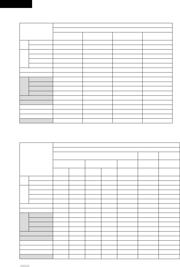
ENGLISH
56
2Table of Surround Mode Parameters (1)
Presence/absence of signals and controllability in the various modes
Channel output
FRONT
L/R CENTER SURROUND
L/R SUB-WOOFER
Surround Mode
DVS: Dolby Virtual Speaker
DHP: Dolby Headphone
REFERENCE
WIDE
DH1
DH2
DH3
BYPASS
STEREO
DIRECT
DOLBY DIGITAL
DTS SURROUND
DOLBY PL II
AUTO STEREO
5CH STEREO
MONO MOVIE
ROCK ARENA
JAZZ CLUB
VIDEO GAME
MATRIX
C
C
C(H/P ONLY)
C(H/P ONLY)
C(H/P ONLY)
C(H/P ONLY)
C
C
C
C
C
C
C
C
C
C
C
C
B
B
E
E
E
E
E
E
B
B
B
E
B
B
B
B
B
B
E
B
E
E
E
E
E
E
B
B
B
E
B
B
B
B
B
B
B
B
E
E
E
E
B
B
B
B
B
B
B
B
B
B
B
B
AUTO
DECODE DVS
DHP
2Table of Surround Mode Parameters (2)
Presence/absence of signals and controllability in the various modes
Playback signals and surround modes for the various input functions
(D.AUX / L2) LINE1 / LINE2 /
TUNER
DVD / D.AUX (D.AUX / L2)
When playing Dolby Digital
signals When playing DTS signals When playing
PCM signals
When playing
analog signals
When playing
analog signals
2-channel Multi-
channel 2-channel Multi-
channel 2-channel 2-channel 2-channel
Surround Mode
DVS: Dolby Virtual Speaker
DHP: Dolby Headphone
REFERENCE
WIDE
DH1
DH2
DH3
BYPASS
STEREO
DIRECT
DOLBY DIGITAL
DTS SURROUND
DOLBY PL II
AUTO STEREO
5CH STEREO
MONO MOVIE
ROCK ARENA
JAZZ CLUB
VIDEO GAME
MATRIX
4PL II
4PL II
4PL II
4PL II
4PL II
C
C
C
C
E
4PL II
4
C
C
C
C
C
C
C
C
C
C
C
CD.MIX
CD.MIX
CD.MIX
C
E
E
E
C
C
C
C
C
C
4PL II
4PL II
4PL II
4PL II
4PL II
C
C
C
E
E
4PL II
4
C
C
C
C
C
C
C4PL II 4PL II 4PL II
C4PL II 4PL II 4PL II
C4PL II 4PL II 4PL II
C4PL II 4PL II 4PL II
C4PL II 4PL II 4PL II
CD.MIX CCC
CD.MIX CCC
CD.MIX CCC
EE E E
CE E E
E4PL II 4PL II 4PL II
E44E
CC C C
CC C C
CC C C
CC C C
CC C C
CC C C
AUTO
DECODE DVS
DHP
B: Can be either present or absent, depending on speaker configuration setting.
: Only usable when center or surround speakers set to be used with the speaker configuration setting.
C: Signal present or controllable. D.MIX: Compatible with down-mixing.
4: Can be selected with 2-channel decode mode. PL II: Compatible with PL II processing.
E: No signal or not controllable.

57
ENGLISH
2Table of Surround Mode Parameters (3)
Presence/absence of signals and controllability in the various modes
Surround parameter – default value indicated in (parentheses)
Pro Logic II Music mode only
SDB TONE
CONTROL
2ch
DECODE
MODE PANORAMA DIMENSION CENTER WIDTH
Surround Mode
DVS: Dolby Virtual Speaker
DHP: Dolby Headphone
REFERENCE
WIDE
DH1
DH2
DH3
BYPASS
STEREO
DIRECT
DOLBY DIGITAL
DTS SURROUND
DOLBY PL II
AUTO STEREO
5CH STEREO
MONO MOVIE
ROCK ARENA
JAZZ CLUB
VIDEO GAME
MATRIX
C (OFF)
C (OFF)
C (OFF)
C (OFF)
C (OFF)
C (OFF)
C (OFF)
E
C (OFF)
C (OFF)
C (OFF)
C (OFF)
C (OFF)
C (OFF)
C (OFF)
C (OFF)
C (OFF)
C (OFF)
C (OFF)
C (OFF)
C (OFF)
C (OFF)
C (OFF)
C (OFF) E
C (OFF)
E
C (OFF)
C (OFF)
C (OFF)
C (OFF)
C (OFF)
C (OFF)
C (OFF)
C (OFF)
C (OFF)
C (OFF)
C
(VIRTUAL1)
C*2
(CINEMA)
E
E
C*1
(AUTO
STEREO)
E
E
E
E
E
E
EEE
EEE
EEE
EEE
EEE
EEE
EEE
EEE
EEE
EEE
C (OFF) C (3) C (3)
EEE
EEE
EEE
EEE
EEE
EEE
EEE
AUTO
DECODE DVS
DHP
2Table of Surround Mode Parameters (4)
Presence/absence of signals and controllability in the various modes
Surround parameter – default value indicated in (parentheses)
Dolby Digital/DTS signal
ROOM
SIZE
EFFECT
LEVEL
DELAY
TIME D. COMP. LFE
Surround Mode
DVS: Dolby Virtual Speaker
DHP: Dolby Headphone
REFERENCE
WIDE
DH1
DH2
DH3
BYPASS
STEREO
DIRECT
DOLBY DIGITAL
DTS SURROUND
DOLBY PL II
AUTO STEREO
5CH STEREO
MONO MOVIE
ROCK ARENA
JAZZ CLUB
VIDEO GAME
MATRIX
E
E
E
E
E
E
E
E
E
E
E
E
E
C (MEDIUM)
C (MEDIUM)
C (MEDIUM)
C (MEDIUM)
E
E
E
E
E
E
E
E
E
E
E
E
E
E
C (10)
C (10))
C (10)
C (10)
E
E
E
E
E
E
E
E
E
E
E
E
E
E
E
E
E
E
C (30ms)
C (OFF) C (0dB)
C (OFF) C (0dB)
C (OFF) C (0dB)
C (OFF) C (0dB)
C (OFF) C (0dB)
C (OFF) C (0dB)
C (OFF) C (0dB)
C (OFF) C (0dB)
C (OFF) C (0dB)
C (OFF) C (0dB)
C (OFF) C (0dB)
EE
C (OFF) C (0dB)
C (OFF) C (0dB)
C (OFF) C (0dB)
C (OFF) C (0dB)
C (OFF) C (0dB)
C (OFF) C (0dB)
AUTO
DECODE DVS
DHP
: Only usable when center or surround speakers set to be used with the speaker configuration setting.
C: Signal present or controllable.
E: No signal or not controllable.
*1 : Auto Stereo mode or Dolby PL II mode (Cinema, Music or Dolby PL mode) selectable.
*2 : Dolby PL II mode (Cinema, Music or Music 2 mode) selectable.
D.MIX: Compatible with down-mixing.
( ): Parameter’s default value

ENGLISH
58
(3) Playback using the Dolby Headphone mode
•The ADV-M71 is equipped with the Dolby Headphone mode, a technology developed jointly by Dolby Laboratories and Lake Technology for
achieving 3D sound over regular headphones.
•The Dolby Headphone mode is set when headphones are connected to the ADV-M71’s headphones jack.
•There are actually four Dolby Headphone modes creating different sound field effects: DH1, DH2, DH3 and Bypass (normal stereo playback).
•The Dolby Headphone mode is compatible with Dolby Digital and DTS multi-channel sources. With 2-channel sources, playback in the Cinema,
Music 1 and Music 2 modes can be selected with the 2-channel mode setting.
B
BAND
PHONES
VOLUME
ON / STANDBY
DVD SURROUND RECEIVER ADV-M71
TONE/SDB
FUNCTION
MENU/SET +
-
SURROUND/SELECT
PUSH
-
PARAM.
2,3
1
RC-966
A / V
3
STAT US
RETURN
ANGLE AUDIO
SUB TITLE
SETUP TONE /SDB
FUNCTIONSURROUNDINPUT MODETEST TONE
DVD
ENTER
MUTING
DISPLAY MENU
TOP MENU
SYSTEM MD
CDR TAPE
TUNER TV / VCR
SURROUND
PARAMETER
CH SELECT
-
+
VCR CH
IN/SURR.
IN/SURR.
DVD
9
8
21
76
+
-
3
2
1Connect headphones (sold separately) to the headphones
jack.
•When headphones are plugged in, the output to the
speakers is automatically turned off and no sound is
produced from the speakers.
PHONES
2Press the surround parameter button and display the
surround parameters.
When the function is set to DVD, this is also shown on the
display.
SURROUND/ SELECT
PUSH
-
PARAM.
Main unit
SURROUND
PARAMETER
Remote control unit
3Set the various surround parameters.
If nothing is done for 6 seconds from when the parameter
is displayed, the normal display reappears.
SURROUND/ SELECT
PUSH
-
PARAM.
Main unit Remote control unit
•Dolby H mode setting
DH2 DH3 BYPASS
,/
DH1
•2-channel mode setting
•The mode switches as shown below each time a button is
operated.
CINEMA
MUSIC2 MUSIC1
Can be selected when there is no signal or when playing a
2-channel source.
There are also the same parameters as those described under
“(2) Playing in the Dolby Virtual Speaker mode”, namely:
BD.COMP. setting
BLFE level setting
BDEFAULT setting
When the surround parameters are displayed, use the •and ª
cursor buttons on the remote control unit to switch to previous or
following items.
HDH1
2 CINEMA

59
ENGLISH
Surround parameters (4)
DOLBY H (Dolby Headphone modes)
DH1 ..............Reference room
(small room with little reverberation)
DH2 ..............Live room
(room with more reverberation than DH1)
DH3 ..............Large room
(Larger room than DH1. Use this mode to achieve a
sense of distance and diffusion of the sound.)
BYPASS ........Stereo playback.
2-channel modes
These can be selected when playing 2-channel sources (analog,
PCM, etc.). The signals are processed by one of the following
decoders to achieve multiple channels then played in the Dolby
Headphone mode.
In the Bypass mode, these are not displayed.
CINEMA .......Dolby Pro Logic II Cinema mode
MUSIC1 ........Dolby Pro Logic II Music mode
MUSIC2 ........Signals played in the Dolby Headphone mode with 2
channels.
2Recording
When playing digital input sources, including function DVDs, signals
encoded in the Dolby Headphone mode are output from the recording
output terminals and can be recorded on other recording devices.
qConnect headphones to the headphones jack.
wSignals encoded in the Dolby Headphone mode are output from
the recording output terminals (in analog).
eSelect the parameters, set the desired mode and start recording.
NOTES:
•Dolby Headphone processing makes the analog recording output
level lower than the normal stereo recording output level.
•Do not change the parameters or unplug the headphones during
recording. Doing so will cause interruptions in the recorded sound.
•Dolby Headphone signals cannot be recorded during playback of
analog sources. The analog input signals are output as such from
the recording output terminals.
(4) Playing in the Auto Decode Mode (only with multi-channel speaker settings)
•The auto decode mode can be selected when the ADV-M71 is used in combination with a subwoofer with built-in amplifier and power amplifier,
center or surround speaker system and a multi-channel speaker configuration (5.1 channels, etc.) is set.
•To make the 5.1-channel setting, set the speakers to “5.1CH SURROUND” in the quick system setup and select “Room Setting” and “Listening
Position”. (See pages 31 to 32.)
•In the auto decode mode, multi-channel playback of multi-channel sources (Dolby Digital or DTS) can be performed automatically according to
the format of the input signals.
•For 2-channel sources as well, playback is possible in the Auto Stereo, Dolby Pro Logic II Cinema, Dolby Pro Logic II Music or Dolby Pro Logic
mode, as set by the 2-channel mode setting. (Two channels of stereo signals are played in the Auto Stereo mode. In other modes playback is
multi-channel.)
[1] Dolby Digital and DTS surround playback (for digital inputs only)
•The applicable sources and procedures are the same as those described at “[1] Playing Dolby Digital and DTS surround sound” under “(1)
Playing in the Dolby Virtual Speaker mode”.
•At step 3, set the surround mode to “AUTO DECODE”. The sound is played according to the format of the input signals.
•At step 6 there are no Dolby Virtual Speaker mode surround parameters.
[2] 2-channel mode setting
•With the auto decode mode, one of four multi-channel playback modes, namely stereo 2-channel playback in the Auto Stereo mode (factory
default), Dolby Pro Logic II Cinema, Dolby Pro Logic II Music and Dolby Pro Logic, can be selected and set for 2-channel sources.
“Auto Stereo” mode cannot be selected for with functions only analog inputs (TUNER, LINE-1, LINE-2). To play such signals in stereo, set the
surround mode to “STEREO”. (See page 45.)
•Operations are the same as those described at “[2] 2-channel mode settings” under “(1) Playing in the Dolby Virtual Speaker mode” on page
52.
•At step 1, set the surround mode to “AUTO DECODE”.
•The 2-channel modes selectable at step 3 are as follows:
PLII CINEMA
PRO LOGIC
AUTO ST
PLII MUSIC
Auto Stereo can be selected when the function is set to DVD or D.AUX.
•For the 2-channel mode surround parameters in the auto decode mode, refer to “Surround parameters (5)” (auto decode 2-channel mode).

ENGLISH
60
Surround parameters (5) (2-channel mode)
AUTO-ST (auto stereo) mode
2-channel sources are played in 2-channel stereo.
When this mode is selected in the auto decode mode, multi-channel sources (DVD, BS digital, etc.) are played in the multi-channel mode,
while 2-channel sources (CDs, etc.) are automatically played in stereo.
PLII CINEMA / PLII MUSIC / PRO LOGIC mode
Even 2-channel sources undergo Dolby Pro Logic II processing and are played in the multi-channel mode.
Dolby Digital Pro-Logic II processing is applied to 2-channel sources as well to play them in the multi-channel mode.
When this mode is selected in the auto decode mode, multi-channel sources (DVD, BS digital, etc.) are played in the multi-channel mode,
and 2-channel sources (CDs, etc.) are also automatically processed with Dolby Digital Pro-Logic II and played in the multi-channel mode.
•PLII CINEMA (Dolby Pro Logic II CINEMA) mode
This mode is suited for playing movies recorded in Dolby Surround as well as regular sources recorded in stereo. A high precision decoder
decodes the signals into 5 channels, resulting in uniform 360 degree surround sound even with 2-channel sources.
The MUSIC mode may be more effective for sources containing a high ratio of stereo music. Try both and choose the most effective
mode.
•PLII MUSIC (Dolby Pro Logic II MUSIC) mode
This mode is suited for surround playback of stereo music signals. The inverted phase signals (the reverberation component of the music
signals contains a high ratio of these) are played from the surround channel, and at the same time the frequency response of the surround
channel is optimized to achieve a natural sound with a sense of expansion.
With music signals, the sound field expansion differs greatly according to the type of music, the recording conditions (live, etc.) and the
contents of the signal source. Because of this, the MUSIC mode includes optional parameters for further adjusting the sound field.
•PANORAMA
The front stereo sound field image is extended to the surround channel.
This is effective if under normal conditions the stereo image is narrow and the surround effect seems weak.
•DIMENSION
This shifts the center of the sound field image to the front or surround side.
The playback balance of the different channels can be adjusted regardless of the amount of reverberation component in the source. If
the sound field image is biased towards the front or surround side, this optional parameter can be used to correct it.
•CENTER WIDTH
This adjusts the method of playback of the center signal component from the center channel only to the front channel only.
When the center channel is played in a way prioritizing separation, the position of the front channel sound field is clearer but the overall
sound field image concentrates at the center and the relationship between the different channels seems weaker. This parameter can
be adjusted to improve the sense of stability of the sound field image and achieve natural horizontal expansion.
•PRO LOGIC (Dolby Pro Logic) mode
This is the conventional Dolby Pro Logic compatible mode. In this mode sources recorded in Dolby Surround are decoded with a
playback image faithful to the original recording.
•In the auto decode mode, the play mode switches automatically as shown below according to the content of the disc being played or program
being received. (When the input mode is set to “AUTO” and the 2-channel mode is set to “AUTO ST”)
Source
DVD
CD
Content
5.1/6.1-channel Dolby Digital
2-channel Dolby Digital
(including 2-channel Dolby Surround)
5.1/6.1-channel DTS digital
PCM stereo
Play mode
5.1-channel playback
Stereo playback ( )
5.1-channel playback
Stereo playback ( )
( ) To play 2-channel surround (Dolby Surround) or stereo sources in the 5.1-channel
surround mode, set the 2-channel mode to something other than “AUTO ST”.

61
ENGLISH
[3] Setting the parameters in the PLII Cinema, PLII Music and Pro Logic modes
• When PLII Cinema, PLII Music or Pro Logic is selected for the 2-channel mode, detailed parameters can be set for each of these modes.
PLII Music mode: Make the settings using the procedure below.
• Program sources including the mark and CDs and other 2-channel sources are decoded with Dolby Pro Logic II
processing and played in the multi-channel mode.
qPLII Cinema mode: This mode is suited for movies and other Dolby Surround programs.
wPLII Music mode: This mode is suited for stereo music programs.
ePro Logic compatible mode: This is the original Dolby Surround Pro Logic mode.
+
-
+
-
RC-966
A / V
3
SEARCH MODEREPEAT RANDOMPROG/DIRECT
MEMO BANDMODE
STAT US
RETURN
ANGLE AUDIO
SUB TITLE
SETUP TONE /SDB
FUNCTIONSURROUNDINPUT MODETEST TONE
DVD
TUNER
CH
321
654
987
0/10
CALL
ENTER
MUTING
+10
DISPLAY MENU
TOP MENU
SYSTEM MD
CDR TAPE
TUNER TV / VCR
SURROUND
PARAMETER
CH SELECT
TUNING /
TV VOL
TUNERDVD
MD/ LINE-1 TAPE/ LINE-2
AUTO DECODE
VIRTUALDIRECT
5CH STEREO
STEREO
D.AUX
-
+
VCR CH
IN/SURR.
IN/SURR.
DVD
9
8
21
76
+
-
CD SRS
RTCT
PTYRDS
3
2
1Select “PLII C”, “PLII M” or “PRO LOGIC” for the 2-channel
mode setting.
2Set the surround parameters for the selected mode.
• The parameters switch as shown below each time one of
the buttons is pressed.
SURROUND/ SELECT
PUSH
-
PARAM.
Main unit
SURROUND
PARAMETER
Remote control unit
DEFAULT
PL CINEMA
PANORAMA
DIMENSION
CNTR WIDTH
DEFAULT
PL MUSIC
DEFAULT
PRO LOGIC
3Set the various surround parameters.
• Panorama setting
PANORA ON OFF
ON
OFF
The selected setting flashes.
• Dimension setting
DIMENSION 3
• Center Width setting
CNTR WIDTH 3
• Default setting
DEFAULT Y/N
When “YES” is selected, the settings are restored to the
factory defaults.
Once the surround parameters have been set, stop operating the
buttons. After several seconds, the normal display reappears and
the settings are automatically entered.
This completes the setting of the parameters.
NOTE:
• The 2-channel mode is set and stored in the memory individually
for the different functions.
,/
0 3 6
,/
... ...
0 3 7
,/
... ...
YES Y/NNO
,/
SURROUND/ SELECT
PUSH
-
PARAM.
Main unit Remote control unit
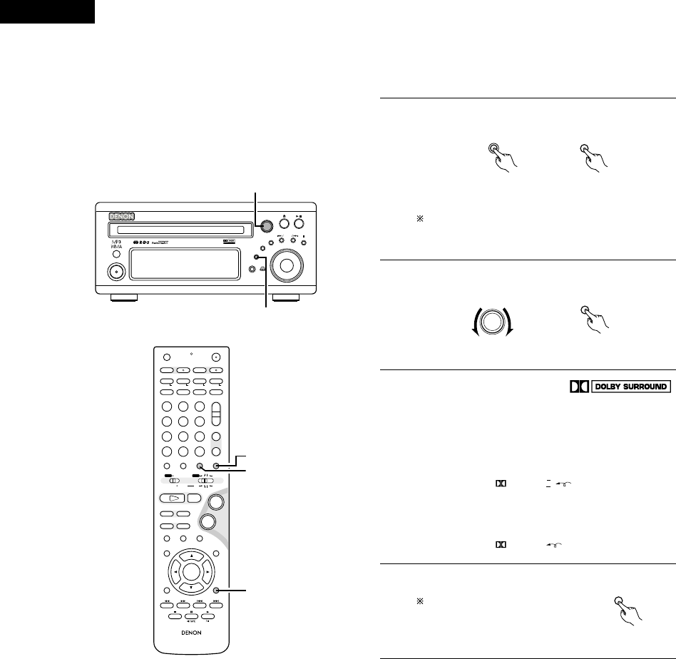
ENGLISH
62
[4] Playing in the Dolby Pro Logic II mode (all functions)
• The source is played according to the settings that have been made for the 2-channel mode and the parameters in the PLII Cinema, PLII Music
and Pro Logic modes.
• Applicable sources
• Digital input signals (D.AUX functions, including DVD playback
discs)
Dolby Digital 2-channel sources
PCM 2-channel sources
• 2-channel analog input signals (TUNER, LINE-1 and LINE-2)
B
BAND
PHONES
VOLUME
ON / STANDBY
DVD SURROUND RECEIVER ADV-M71
TONE/SDB
FUNCTION
MENU/SET +
-
SURROUND/SELECT
PUSH
-
PARAM.
2
1
+
-
+
-
RC-966
A / V
3
A-B REPEAT
SEARCH MODE
ONOFF
REPEAT RANDOM
CLEAR ZOOMSLIDE MODE
PROG/ DIRECT
MEMO BANDMODE
STAT US
RETURN
ANGLE AUDIO
SUB TITLE
SETUP TONE /SDB
FUNCTIONSURROUNDINPUT MODETEST TONE
DVD
TUNER
CH
3
-
+
21
654
987
0/10
CALL
ENTER
MUTING
+10
DISPLAY MENU
TOP MENU
SYSTEM MD
CDR TAPE
TUNER TV / VCR
SURROUND
PARAMETER
CH SELECT
VCR
NTSC/PAL
SLEEP
ENTER EDIT/MENUCHARAC.
REC
TIMETITLE
TUNING /
TV VOL
TV CH TV CH
TUNERDVD
MD/ LINE-1 TAPE/ LINE-2
AUTO DECODE
VIRTUALDIRECT
5CH STEREO
STEREO
D.AUX
-
+
VCR CH
IN/SURR.
IN/SURR.
DVD
T VTV INSOURCE
9
8
21
76
+
-
CD SRS
RTCT
PTYRDS
4
1
2
1Select the input function.
FUNCTION
Main unit
FUNCTION
Remote control unit
2Set the surround mode to “AUTO DECODE”.
SURROUND/ SELECT
PUSH
-
PARAM.
SURROUND
Main unit Remote control unit
In the “DTS” input mode with the function set to a digital
input (DVD or D.AUX), it is not possible to play in the Dolby
Pro Logic II mode.
3
Play a program source including the
mark or a 2-channel source.
• The source is played according to the Dolby Pro Logic II
mode settings.
• In the Cinema and Music modes, the Dolby Pro Logic II
indicator lights.
PRO LOGIC II
Lit
• In the Dolby Pro Logic mode, the Dolby Pro Logic indicator
lights
PRO LOGIC
Lit
4Set the surround parameters
according to the selected mode.
Refer to steps 1to 3under
“Setting the parameters in the
PLII Cinema, PLII Music and Pro
Logic modes” (page 61).
SURROUND
PARAMETER
Remote control unit
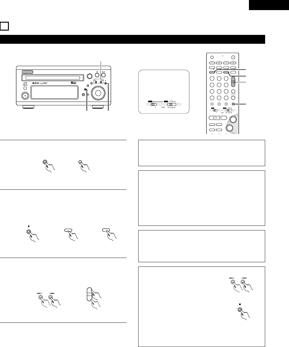
63
ENGLISH
15
LISTENING TO THE RADIO
1Press the FUNCTION button and select “TUNER”.
2Select “FM” or “AM”.
• The selected “FM AUTO”, “FM MONO” or “AM” is
displayed.
• When using the remote control, the mode button is used to
select FM AUTO and MONO.
3Adjust the receiving frequency.
• When a station is received, the “TUNED” indication will
light.
NOTE:
A humming sound may be heard when using a TV nearby while
receiving AM programs. If this happens, move the system as far
from the TV as possible.
Auto tuning
• When one of the Tuning +/– button is pressed, the frequency
changes in steps of 50 kHz in the FM band, 9 kHz in the AM
band.
• If one of the Tuning +/– button is held for over 1 second, the
frequency continues to change when the button is released
(auto tuning) and stops when a station is tuned in.Tuning will not
stop at stations whose reception is poor.
• To stop the auto tuning function, press the Tuning +/– button
once.
FM Stereo Reception
• When a program being broadcast in “FM AUTO” is received,
the “ST” indicator lights and the program is received in stereo.
• If reception is poor and there is much noise in the stereo signals,
press the BAND or MODE button to set the FM MONO mode.
(1) Tuning
Example: Tuning in FM/AM stations
B
BAND
PHONES
VOLUME
ON / STANDBY
DVD SURROUND RECEIVER ADV-M71
TONE/SDB
FUNCTION
MENU/SET +
-
SURROUND/SELECT
PUSH
-
PARAM.
12
3
FUNCTION
FUNCTION
Main unit Remote control unit
BAND
RANDOM
BAND
Main unit Remote control unit
+
-
+
-
A / V
A-B REPEAT
SEARCH MODE
ONOFF
REPEAT RANDOM
CLEAR ZOOMSLIDE MODE
PROG/ DIRECT
MEMO BANDMODE
STAT US
FUNCTIONSURROUNDINPUT MODETEST TONE
DVD
TUNER
CH
3
-
+
21
654
987
0/10
CALL
+10
SYSTEM MD
CDR TAPE
TUNER TV / VCR
VCR
NTSC/PAL
SLEEP
ENTER EDIT/MENUCHARAC.
REC
TIMETITLE
TUNING /
TV VOL
TV CH TV CH
TUNERDVD
MD/ LINE-1 TAPE/ LINE-2
AUTO DECODE
VIRTUALDIRECT
5CH STEREO
STEREO
D.AUX
IN/SURR.
IN/SURR.
DVD
T VTV INSOURCE
9
8
21
76
+
-
CD SRS
RTCT
PTYRDS
2
2
3
1
+
-
+
-
TUNING /
Main unit Remote control unit
A / V
SYSTEM MD
CDR TAPE
TUNER TV / VCR
IN/SURR.
IN/SURR.
DVD
Set the remote
control selector
switches to A/V
and TUNER.
PROG/ DIRECT
MODE
About the tuning mode and the preset mode
• The function of the “–” and “+” buttons
on the main unit can be switched so that
they can be used for either tuning
(selecting the reception frequency) or for
selecting preset stations.
• The buttons are set to the tuning mode
upon shipment. The mode can be switched
to the preset mode by pressing the “+”
button while pressing in the BAND button.
(When this is done, “PRESET” is flashes for
approximately 5 seconds.)
• Press the “–” button while pressing in the BAND button to
switch to the tuning mode. (When this is done, “TUNING” is
flashes for approximately 5 seconds.)
+
-
Main unit
BAND
Main unit

ENGLISH
64
(2) Presetting stations that have been tuned in and giving names to stations (remote control unit
only)
2A total of 40 stations (including both FM and AM stations) can be preset.
2Preset stations can be given names with up to 8 characters (letters, numbers and symbols).
2Preset stations using the including remote control unit.
1Tune in the station you want to preset.
P0- FM 92.50M
+
-
+
-
A/V
A-B REPEAT
SEARCH MODEREPEAT RANDOM
CLEAR ZOOMSLIDE MODE
PROG/ DIRECT
MEMO BANDMODE
FUNCTIONSURROUNDINPUT MODETEST TONE
TUNER
CH
3
-
+
21
654
987
0/10
CALL
+10
TUNER TV / VCR
NTSC/PAL
SLEEP
ENTER EDIT/MENUCHARAC.
REC
TIMETITLE
TUNING /
TV VOL
TV CH TV CH
TUNERDVD
MD/ LINE-1 TAPE/ LINE-2
AUTO DECODE
VIRTUALDIRECT
5CH STEREO
STEREO
D.AUX
IN/SURR
DVD
T VTV INSOURCE
CD SRS
RTCT
PTYRDS
2,3,
4,6
3,5
2Press the MEMO button twice in a row.
• The name input mode is set.
REPEAT
MEMO
Remote control unit
P0- _
3Use the “+” and “–” preset buttons to select the character,
then press the MEMO button to input that character.
+
-
TUNER
CH
Remote control unit
• When the “+” TUNING button or the MEMO button is
pressed, the selected character is entered, the cursor
moves to the next position and the next character can be
input.
• Use the “–” TUNING button to move back to the previous
position. Use this to correct characters that have already
been input.
P0- F
\
P0- F_
REPEAT
MEMO
Remote control unit
4Press the MEMO button twice in a row to enter the station
name you have input.
• The preset number indicator, “P”,
flashes.
REPEAT
MEMO
Remote control unit
P0- FM-DENON
5Use the “+” and “–” preset buttons to
select the preset number.
6Press the MEMO button to enter the preset number.
• The preset number, band and reception frequency are
displayed, then the station name appears.
+
-
TUNER
CH
Remote control unit
P03 FM-DENON
The preset number can also be input directly using the +10
and 1 to 10 buttons on the numeric keypad.
P03 FM 92.50M
\
P03 FM-DENON
REPEAT
MEMO
Remote control unit
To stop in the middle of the procedure,
press the MODE button before pressing
the MEMO button at step 4. Everything
you have input is cleared.
To clear a station name that has been set in
the memory, call out that station, set the
name input mode in step 2, then press the
MODE button. The station name is cleared
and the preset channel frequency is
displayed.
If you only want to preset a station, press the MEMO button once
while the station is tuned in. The preset number indicator, “P”,
flashes, and the preset number input mode is set. Use the “+” and
“–” preset buttons to select the preset number then press the
MEMO button again to store that station at the selected number.
(The number can also be specified directly using the +10 and 1 to
10 buttons on the numeric keypad.)
+
-
TUNER
CH
REPEAT
MEMO
Remote control unit Remote control unit
PROG/ DIRECT
MODE
Remote control unit
A / V
SYSTEM MD
CDR TAPE
TUNER TV / VCR
IN/SURR.
IN/SURR.
DVD
Set the remote
control selector
switches to A/V
and TUNER.

65
ENGLISH
(3) Auto tuner presets
Use this to automatically search for FM broadcasts and store up to 40 stations at preset channels 1 to 40.
NOTE:
• If an FM station cannot be preset automatically due to poor reception, use the “Manual tuning” operation to tune in the station, then preset it
using the manual “Preset memory” operation.
B
BAND
PHONES
VOLUME
ON / STANDBY
DVD SURROUND RECEIVER ADV-M71
TONE/SDB
FUNCTION
MENU/SET +
-
SURROUND/SELECT
PUSH
-
PARAM.
1
2
1Using the TUNER function, press and
hold the MENU/SET button of the main
unit for 2 seconds or longer.
• “AUTO PRESET?” and “–: NO/+:
START” will alternately appear on the
display of the main unit.
2Use the TUNING + button to select
“START”.
“SEARCH” flashes on the display and
searching begins.
“COMPLETED” appears once searching
is completed.
• Press the TUNING – button to cancel.
MENU/SET
Main unit
+
Main unit
(4) Listening to preset stations
Example: Listening to the station preset at number P03 (This operation is only possible from the remote control unit.)
1Use the “+” and “–” preset buttons to select preset number
“3” or press the “3” button on the numeric keypad to display
preset number “P03”.
The “+” and “–” buttons on the main unit can be selected
when the preset mode has been set.
B
BAND
PHONES
VOLUME
ON / STANDBY
DVD SURROUND RECEIVER ADV-M71
TONE/SDB
FUNCTION
MENU/SET +
-
SURROUND/SELECT
PUSH
-
PARAM.
1
+
-
TUNER
CH
Remote control unit
3
D.AUX
+
-
Main unit
The functions of the “+” and “–” buttons on the main unit change
according to whether the tuning or preset mode is set. When the
tuning mode is set, you can switch to the preset mode by pressing
the “+” button while pressing the BAND button.
BAND
+
Main unit Main unit
+
-
+
-
A / V
A-B REPEAT
SEARCH MODE
ONOFF
REPEAT RANDOM
CLEAR ZOOMSLIDE MODE
PROG/ DIRECT
MEMO BANDMODE
FUNCTIONSURROUNDINPUT MODETEST TONE
TUNER
CH
3
-
+
21
654
987
0/10
CALL
+10
SYSTEM MD
CDR TAPE
TUNER TV / VCR
VCR
NTSC/PAL
SLEEP
ENTER EDIT/MENUCHARAC.
REC
TIMETITLE
TUNING /
TV VOL
TV CH TV CH
TUNERDVD
MD/ LINE-1 TAPE/ LINE-2
AUTO DECODE
VIRTUALDIRECT
5CH STEREO
STEREO
D.AUX
IN/SURR.
IN/SURR.
DVD
T VTV INSOURCE
CD SRS
RTCT
PTYRDS
1
1
The preset buttons on the remote control unit (TUNER CH “+” and
“–”) can be used at any time.
A / V
SYSTEM MD
CDR TAPE
TUNER TV / VCR
IN/SURR.
IN/SURR.
DVD
Set the remote
control selector
switches to A/V
and TUNER.

ENGLISH
66
NEWS
AFFAIRS
INFO
SPORT
EDUCATE
ROCK M
EASY M
LIGHT M
CLASSICS
OTHER M
PHONE IN
TRAVEL
LEISURE
JAZZ
COUNTRY
DRAMA
CULTURE
SCIENCE
VARIED
POP M
WEATHER
FINANCE
CHILDREN
SOCIAL
RELIGION
NATION M
OLDIES
FOLK M
DOCUMENT
News
Affairs
Information
Sports
Education
Drama
Culture
Science
Varied
Pop Music
Rock Music
Easy Listening
Light Classical
Serious Classical
Other Music
Weather &
Meteorological
Finance
Children’s
Progs
Social Affairs
Religion
Phone In
Travel & Touring
Leisure &
Hobby
Jazz Music
Country Music
National Music
Oldies Music
Folk Music
Documentary
(5) RDS (Radio Data System)
RDS (works only on the FM band) is a broadcasting service which allows station to send additional information along with the regular radio program
signal.
The following three types of RDS information can be received on this unit:
2Program Type (PTY)
PTY identifies the type of RDS program.
The program types and their displays are as follows:
2Traffic Program (TP)
TP identifies programs that carry traffic announcements.
This allows you to easily find out the latest traffic conditions in your area before you leaving home.
2Radio Text (RT)
RT allows the RDS station to send text messages that appear on the display.
NOTE: The operations described below using the RDS, PTY and RT buttons will not function in areas in which there are no RDS broadcasts.
(6) RDS search
Use this function to automatically tune to FM stations that provide RDS service.
+
-
+
-
A / V
A-B REPEAT
SEARCH MODE
ONOFF
REPEAT RANDOM
CLEAR ZOOMSLIDE MODE
PROG/ DIRECT
MEMO BANDMODE
FUNCTIONSURROUNDINPUT MODETEST TONE
TUNER
CH
3
-
+
21
654
987
0/10
CALL
+10
SYSTEM MD
CDR TAPE
TUNER TV / VCR
VCR
NTSC/PAL
SLEEP
ENTER EDIT/MENUCHARAC.
REC
TIMETITLE
TUNING /
TV VOL
TV CH TV CH
TUNERDVD
MD/ LINE-1 TAPE/ LINE-2
AUTO DECODE
VIRTUALDIRECT
5CH STEREO
STEREO
D.AUX
IN/SURR.
IN/SURR.
DVD
T VTV INSOURCE
CD SRS
RTCT
PTYRDS
21
3
1Set the band to “FM”.
2Press the RDS button until “RDS
SEARCH” appears on the display.
RANDOM
BAND
Remote control unit
CLEAR
Remote control unit
3Press the TUNING + (UP) or – (DOWN)
button to automatically begin the RDS
search operation.
+
-
TUNING /
TV VOL
Remote control unit
4When a broadcast station is found, that station’s name
appears on the display.
• If no RDS station is found when all the frequencies are searched,
“NO PROGRAMME” is displayed.
A / V
SYSTEM MD
CDR TAPE
TUNER TV / VCR
IN/SURR.
IN/SURR.
DVD
Set the remote
control selector
switches to A/V
and TUNER.

67
ENGLISH
• If no station broadcasting the designated program type is found
when all the frequencies are searched, “NO PROGRAMME” is
displayed.
(7) PTY search
Use this function to find RDS stations broadcasting a designated program type (PTY).
For a description of each program type, refer to “Program Type (PTY)”.
1Set the band to “FM”.
2Press the RDS button until “PTY
SEARCH” appears on the display.
+
-
TUNING /
TV VOL
Remote control unit
CLEAR
Remote control unit
3Watching the display, press the PTY
button to call out the desired program
type.
A-B REPEAT
REPEAT
ENTER
Remote control unit
4Press the TUNING + (UP) or – (DOWN)
button to automatically begin the PTY
search operation.
RANDOM
BAND
Remote control unit
5The station name is displayed on the display after searching
stops.
• If no TP station is found when all the frequencies are searched,
“NO PROGRAMME” is displayed.
(8) TP search
Use this function to find RDS stations broadcasting traffic program (TP stations)
1Set the band to “FM”.
2Press the RDS button until “TP
SEARCH” appears on the display.
+
-
TUNING /
TV VOL
Remote control unit
CLEAR
Remote control unit
3Press the TUNING + (UP) or – (DOWN)
button TP search begins.
RANDOM
BAND
Remote control unit
4The station name is displayed on the display after searching
stops.
• When the RT mode is turned on while an RDS radio station not
offering an RT service is tuned in, “NO TEXT DATA” is displayed on
the display, then the mode automatically switches to the PS mode.
• In the same way, the mode automatically switches to the PS mode
when the RT service is finished. In this case, the mode
automatically switches from the PS mode back to the RT mode
when an RT broadcast is resumed.
• The RT mode cannot be set in the AM band or for FM stations not
offering RDS broadcasts.
• To turn the RT mode off, press the RT button and switch to the
desired display mode. (Refer to page 66.)
(9) RT (Radio Text)
“RT” appears on the display when radio text data is received.
1To turn the RT mode on, press the RT
button on the remote control unit until
the RT indicator is lit.
2When the station currently tuned in is offering a radio text
message service, the message scrolls on the display.
ZOOM
+
EDIT/MENU
TV CH
Remote control unit
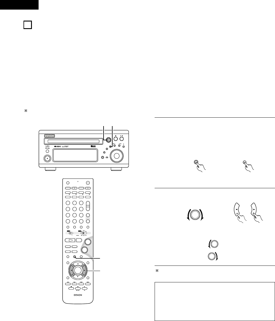
ENGLISH
68
• The ADV-M71 is equipped with an on-screen display (“OSD”) function that displays various types of information on the surround functions and
the disc on the screen when the function is set to DVD.
qSetup screen
• This is used to select the speaker system being used (quick system setting) and to change the function of the ADV-M71 and various settings
when playing discs (system setting change and DVD setting change).
• The setup screen can be used regardless of the currently set function.
wDisplay of disc information
• When the function is set to DVD, the OSD displays information on the disc and appears when various playback functions are operated.
eDisplay of surround function
• When the function is set to DVD, information on the surround amplifier is also displayed and can be operated.
• The OSD for the surround function (AV OSD) can be turned on and off.
(The OSD for the setup screen and DVD disc information cannot be set to
“
OFF”.)
Set to “ON” upon shipment from the factory.
16
ON-SCREEN DISPLAY
B
BAND
PHONES
VOLUME
ON / STANDBY
DVD SURROUND RECEIVER ADV-M71
TONE/SDB
FUNCTION
MENU/SET +
-
SURROUND/SELECT
PUSH
-
PARAM.
12
+
-
+
-
RC-966
A / V
3
A-B REPEAT
SEARCH MODE
ONOFF
REPEAT RANDOM
CLEAR ZOOMSLIDE MODE
PROG/ DIRECT
MEMO BANDMODE
STAT US
RETURN
ANGLE AUDIO
SUB TITLE
SETUP TONE /SDB
FUNCTIONSURROUNDINPUT MODETEST TONE
DVD
TUNER
CH
3
-
+
21
654
987
0/10
CALL
ENTER
MUTING
+10
DISPLAY MENU
TOP MENU
SYSTEM MD
CDR TAPE
TUNER TV / VCR
SURROUND
PARAMETER
CH SELECT
VCR
NTSC/PAL
SLEEP
ENTER EDIT/MENUCHARAC.
REC
TIMETITLE
TUNING /
TV VOL
TV CH TV CH
TUNERDVD
MD/ LINE-1 TAPE/ LINE-2
AUTO DECODE
VIRTUALDIRECT
5CH STEREO
STEREO
D.AUX
-
+
VCR CH
IN/SURR.
IN/SURR.
DVD
T VTV INSOURCE
9
8
21
76
+
-
CD SRS
RTCT
PTYRDS
1
2
1With the function set to DVD, press the STATUS button of the
remote control for at least 2 seconds.
Press in the MENU/SET button on the main unit, then press
the MENU/SET button again for at least 2 seconds while
“STATUS” is displayed.
• “AV OSD ON 0:1OFF” is displayed.
MENU/SET
STAT U S
Main unit Remote control unit
2Turn the AV OSD on or off.
SURROUND/ SELECT
PUSH
-
PARAM.
Main unit Remote control unit
or 0:ON
or 1:OFF
After several seconds, the display turns off and the setting is
made.
NOTES:
• Depending on the disc being played, the picture may be
disturbed when the OSD turns on. This is not a malfunction.
If this should happen, set the AV OSD to “OFF”.
• The OSD is also output to the VCR video output terminals.
Do not perform setup or OSD operations while recording with a
video deck.

69
ENGLISH
17
USING THE ON-SCREEN DISPLAY
(1) Operating using the disc information OSD
1
2
3
In the play mode, press the DISPLAY button.
• The On-Screen Display appears.
• The picture on the TV screen switches each time the button is
pressed.
• The items displayed differ from disc to disc.
Example: For DVDs
Use the and •, ªcursor buttons to select the item you wish to change.
• The selected item is displayed with a yellow frame.
qFor DVDs
“TITLE”, “CHAPTER”, “TITLE ELAPSED” can be selected.
wFor video and music CDs
“TRACK” can be selected.
qChanging the elapsed time
Input using the number buttons, then press the ENTER button.
Example: For 1 minute 26 seconds /“00126”
wChanging the title, track or chapter
• For DVDs
Input using the number buttons, then press the ENTER button.
(For some discs it is not possible to change the title or chapter.)
• For video and music CDs
Input using the number buttons. Playback starts from that track.
DISPLAY
Remote control unit
Remote control unit
Remote control unit
321
654
987
0/10 +10
TUNERDVD
MD/ LINE-1 TAPE/ LINE-2
AUTO DECODE
VIRTUAL
5CH STEREO
STEREO
D.AUX
Example: For video and music CDs • For the on-screen display for video CDs and music
CDs, only the disc time changes.
+
-
+
-
A / V
A-B REPEAT
SEARCH MODEREPEAT RANDOM
CLEAR ZOOMSLIDE MODE
PROG/ DIRECT
MEMO BANDMODE
FUNCTIONSURROUNDINPUT MODETEST TONE
TUNER
CH
3
-
+
21
654
987
0/10
CALL
+10
TUNER TV / VCR
NTSC/PAL
SLEEP
ENTER EDIT/MENUCHARAC.
TIMETITLE
TUNING /
TV VOL
TV CH TV CH
TUNERDVD
MD/ LINE-1 TAPE/ LINE-2
AUTO DECODE
VIRTUALDIRECT
5CH STEREO
STEREO
D.AUX
IN/SURR.
DVD
T VTV INSOURCE
CD SRS
RTCT
PTYRDS
3
RC-966
3
STAT US
RETURN
ANGLE AUDIO
SUB TITLE
SETUP TONE /SDB
ENTER
MUTING
DISPLAY MENU
TOP MENU
SURROUND
PARAMETER
CH SELECT
-
+
VCR CH
1
2
3
2Use this function to display and
change information on the disc
(titles, chapters, time, etc.)
A / V
SYSTEM MD
CDR TAPE
TUNER TV / VCR
IN/SURR.
IN/SURR.
DVD
Set the remote
control selector
switches to A/V
and DVD.
TRACK 01 / 10
26 : 11S I NGL E T IME
TOTAL TIME
PI CTURE MODE STANDARD
S I NGL E REMAIN 03 : 17
TOTAL TIME 06 : 15
TOTAL REMAIN 32 : 05
CHAPTER 01/10
00 : 00 : 01
STANDARD
AUDI O
: OFF
SUBT ITLE 1/2 : DOLBY D 3/2/1 ENGLISH
01 : 10 : 59
00 : 00 : 01
00 : 40 : 59
TITLE 01/10
TITLE TIME
CHAPTER T IME
CHAPTER REMAI N
TITLE REMAIN
PI CTURE MODE
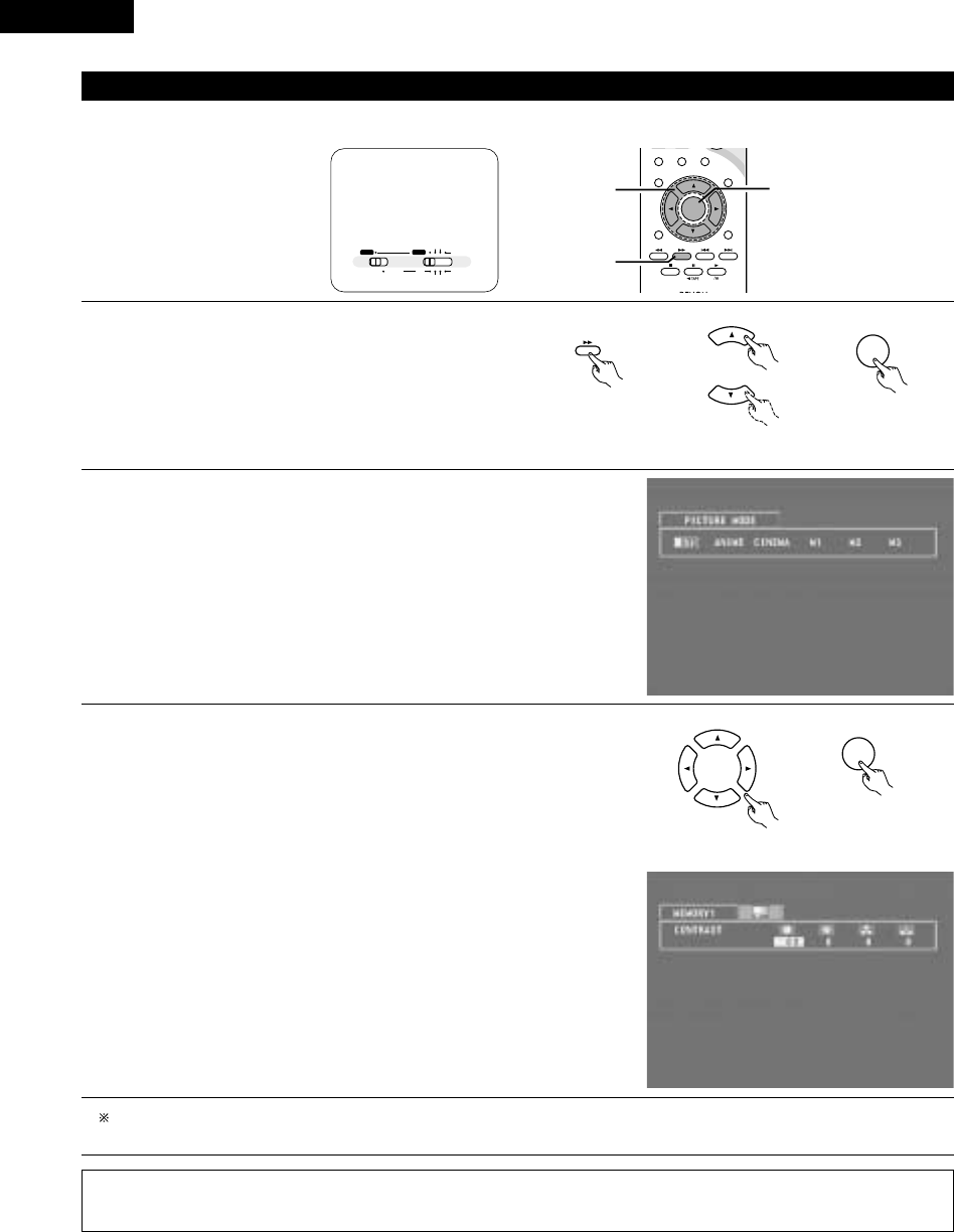
ENGLISH
70
(2) Adjusting the picture quality
• The quality of the picture when playing discs can be adjusted.
3
STAT US
RETURN
ANGLE AUDIO
SUB TITLE
SETUP TONE /SDB
ENTER
MUTING
DISPLAY MENU
TOP MENU
SURROUND
PARAMETER
CH SELECT
-
+
VCR CH
1
1,2,3 1,2
ENTER
1When playing a disc with the function set to DVD, press the
DISPLAY button to turn on the on-screen display, use the •and ª
cursor buttons to select “PICTURE MODE”, then press the
ENTER button.
• The picture quality adjustment screen appears.
• The on-screen display also turns on when the DISPLAY button
is pressed in the stop mode.
Remote control unit
Remote control unit
\
DISPLAY
Remote control unit
\
2Use the 0and 1cursor buttons to select the item, then press the ENTER button.
Standard:
Both the picture quality and functions are set back to the standard settings set
upon shipment from the factory.
Anime:
This sets a brighter more vivid picture quality.
Cinema:
This sets a mellower picture quality.
Memory 1 to 3:
Picture quality settings you have adjusted can be stored at three memory
positions. (Set at step 3)
3Selecting and adjusting the picture quality
Use the 0and 1cursor buttons to select the picture quality item, then use the •
and ªcursor buttons to adjust the value.
• All the adjustments are stored in the memory.
Contrast (–6 to +6) (factory default: 0):
This adjusts the contrast between light and dark portions of the picture.
Brightness (0 to +12) (factory default: 0):
This adjust the brightness (vividness) of the picture.
Color density (–6 to +6) (factory default: 0):
This adjusts the color density.
Hue (–6 to +6) (factory default: 0):
This adjusts the balance between green and red. (This setting does not affect
progressive scan outputs.)
ENTER
Remote control unit
Remote control unit
\
A / V
SYSTEM MD
CDR TAPE
TUNER TV / VCR
IN/SURR.
IN/SURR.
DVD
Set the remote
control selector
switches to A/V
and DVD.
NOTE:
• Depending on the disc being played, the picture or sound may be disturbed when the on-screen display is displayed. This is not a
malfunction.
To complete the picture quality adjustment:
Press the DISPLAY button again.

71
ENGLISH
2Use this function to play your favourite audio or video sections repeatedly.
(3) Playing Repeatedly
[1] Playing Repeatedly (Repeat Playback)
+
-
+
-
A / V
A-B REPEAT
SEARCH MODE
ONOFF
REPEAT RANDOM
CLEAR ZOOMSLIDE MODE
PROG/ DIRECT
MEMO BANDMODE
FUNCTIONSURROUNDINPUT MODETEST TONE
DVD
TUNER
CH
3
-
+
21
654
987
0/10
CALL
+10
SYSTEM MD
CDR TAPE
TUNER TV / VCR
VCR
NTSC/PAL
SLEEP
ENTER EDIT/MENUCHARAC.
REC
TIMETITLE
TUNING /
TV VOL
TV CH TV CH
TUNERDVD
MD/ LINE-1 TAPE/ LINE-2
AUTO DECODE
VIRTUALDIRECT
5CH STEREO
STEREO
D.AUX
IN/SURR.
IN/SURR.
DVD
T VTV INSOURCE
9
8
21 +
CD SRS
RTCT
PTYRDS
[2]
-
1,2
[1]
-
1
1In the play mode, press the REPEAT button.
• The display on the TV screen switches each time the button is
pressed, and the corresponding repeat play or stop mode is set.
lights on the display when the repeat play mode is set. “ALL”
lights when the all repeat play mode is set.
• Normal playback
• Title repeated
• Chapter repeated
• Repeat playback
cancelled
wFor video and music CDs
• Normal playback
• Track repeated
• Entire disc
repeated
• Repeat playback
cancelled
To return to normal playback:
Return to normal playback by pressing the REPEAT button until “REPEAT OFF” appears on the TV screen.
REPEAT
MEMO
Remote control unit
TRACK REPEAT
DISC REPEAT
REPEAT OFF
CHAPTER REPEAT
TITLE REPEAT
REPEAT OFF
qFor DVDs
A / V
SYSTEM MD
CDR TAPE
TUNER TV / VCR
IN/SURR.
IN/SURR.
DVD
Set the remote
control selector
switches to A/V
and DVD.

ENGLISH
72
[2] Playing a Certain Section Repeatedly (A-B Repeat Playback)
1
2
During playback, press the A-B REPEAT button.
• This sets start point A.
Press the A-B REPEAT button again.
• This sets end point B, and repeat playback of the A-B section
starts.
To return to normal playback:
Press the A-B REPEAT button until “A TO B CANCELLED” appears on the TV screen.
Remote control unit
A-B REPEAT
ENTER
Remote control unit
A-B REPEAT
ENTER
NOTES:
• Repeat playback may not work for some DVDs.
• The repeat playback and A-B repeat playback functions will not work for DVDs and video CDs for which the elapsed time is not shown
on the display during playback.
• In some cases, subtitles may not be displayed near the A and B points during A-B repeat playback.
A TO B SET A
A TO B SET B
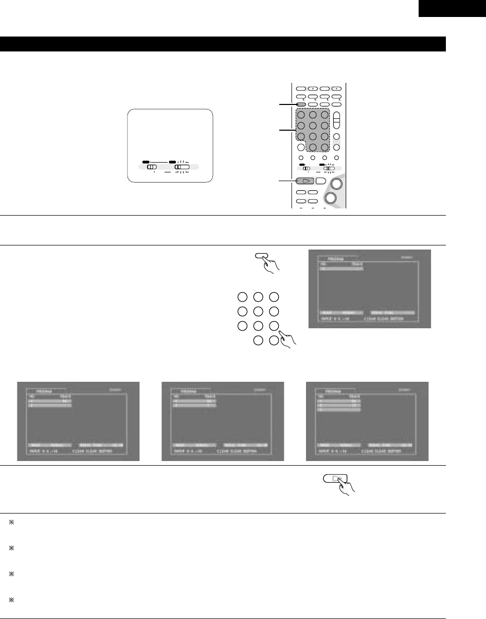
73
ENGLISH
2Use this function with video and music CDs to play the tracks in the desired order.
2This function does not affect with DVD.
(4) Playing Tracks in the Desired Order
1
2
3
Press the PROG/DIRECT button once in the stop mode.
• The program selection screen appears.
Use the number buttons to select the number you want to
program.
• Up to 20 tracks can be programmed.
Press the play button.
• The tracks start playing in the programmed order.
To return to normal playback:
Press the stop button to stop programmed playback, then press the PROG/DIRECT button.
When the play button is next pressed, normal playback begins from the beginning of the disc.
Clearing individual tracks from the program:
Press the stop button to stop programmed playback.
Now press the CLEAR button to clear the last track programmed.
Clearing the entire program:
The entire program is cleared when the power is turned off or the disc is unloaded.
The entire program can also be cleared by pressing the stop button to stop programmed playback then pressing the PROG/DIRECT button.
Checking the programmed tracks:
Press the CALL button to display the programmed tracks in steps.
Press number button “5”.
Remote control unit
321
654
987
0/10 +10
TUNERDVD
MD/ LINE-1 TAPE/ LINE-2
AUTO DECODE
VIRTUAL
5CH STEREO
STEREO
D.AUX
DVD
1
Remote control unit
Press number button “+10”. Press number button “2”.
Remote control unit
PROG/ DIRECT
MODE
+
-
+
-
A / V
A-B REPEAT
SEARCH MODEREPEAT RANDOM
CLEAR ZOOMSLIDE MODE
PROG/ DIRECT
MEMO BANDMODE
STAT US
FUNCTIONSURROUNDINPUT MODETEST TONE
DVD
TUNER
CH
3
-
+
21
654
987
0/10
CALL
+10
SYSTEM MD
CDR TAPE
TUNER TV / VCR
NTSC/PAL
SLEEP
ENTER EDIT/MENUCHARAC.
REC
TIMETITLE
TUNING /
TV VOL
TV CH TV CH
TUNERDVD
MD/ LINE-1 TAPE/ LINE-2
AUTO DECODE
VIRTUALDIRECT
5CH STEREO
STEREO
D.AUX
IN/SURR.
IN/SURR.
DVD
T VTV INSOURCE
9
8
21
76
+
-
CD SRS
RTCT
PTYRDS
1
2
3
A / V
SYSTEM MD
CDR TAPE
TUNER TV / VCR
IN/SURR.
IN/SURR.
DVD
Set the remote
control selector
switches to A/V
and DVD.
Example: To program tracks 5 and 12
\\

ENGLISH
74
2Use this function with video and music CDs to play the tracks in random order.
2This function does not affect with DVD.
(5) Playing Tracks in the Random Order
1
2
In the stop mode, press the RANDOM button.
• The random play screen appears.
Press the PLAY (1) button.
• The tracks start playing in random order.
• Random playback is not possible for some discs.
To return to normal playback:
Press the STOP (2) button to stop random playback, then press the RANDOM button once.
RANDOM
BAND
Remote control unit
DVD
1
Main unit Remote control unit
RANDOM ON
+
-
+
-
A / V
3
A-B REPEAT
SEARCH MODEREPEAT RANDOM
CLEAR ZOOMSLIDE MODE
PROG/ DIRECT
MEMO BANDMODE
STAT US
FUNCTIONSURROUNDINPUT MODETEST TONE
DVD
TUNER
CH
3
-
+
21
654
987
0/10
CALL
MUTING
+10
SYSTEM MD
CDR TAPE
TUNER TV / VCR
NTSC/PAL
SLEEP
ENTER EDIT/MENUCHARAC.
TIMETITLE
TUNING /
TV VOL
TV CH TV CH
TUNERDVD
MD/ LINE-1 TAPE/ LINE-2
AUTO DECODE
VIRTUALDIRECT
5CH STEREO
STEREO
D.AUX
IN/SURR.
IN/SURR.
DVD
T VTV INSOURCE
9
8
21
76
+
-
CD SRS
RTCT
PTYRDS
1
2
A / V
SYSTEM MD
CDR TAPE
TUNER TV / VCR
IN/SURR.
IN/SURR.
DVD
Set the remote
control selector
switches to A/V
and DVD.

75
ENGLISH
[1] Listening to Recorded MP3 CD/CD-R/CD-RW
2There are many music distribution sites on the internet from which music files in MP3 format can be downloaded. Music downloaded as
instructed on the site and written onto a CD-R/RW disc can be played on the ADV-M71.
If music recorded on commercially available music CDs is converted on a computer into MP3 files using an MP3 encoder (conversion software),
the data on a 12 cm CD is reduced into about 1/10 the amount of the original data. Thus, when written in MP3 format, the data of about 10
music CDs can fit onto a single CD-R/RW disc. A single CD-R/RW disc can contain over 100 tracks.
Values when 5-minute tracks are converted with a standard bit rate of 128 kbps into MP3 files and using a CD-R/RW disc with a capacity
of 650 MB.
(6) MP3 WMA Playback
1
Load the CD-R/RW disc on which the MP3 format music
files have been written into this unit. (See page 40.)
• When the disc is loaded in the ADV-M71, the disc
information screen appears.
• If there are multiple folders, proceed to step 2.
• If there are no folders on the disc (if the disc only
contains MP3 files), proceed to step 3.
All the folders recorded on the disc are displayed.
(The folders are not displayed by layer.)
ENTER
2Use the •and ªcursor buttons to select the folder
containing the file(s) you want to play, then press the
ENTER button.
To change the folder
Use the •cursor button to select “ROOT” at the
upper right of the screen, then press the ENTER
button. The screen in step 1reappears. Select the
desired folder.
Remote control unit
Remote control unit
\
-
A / V
3
STAT US
RETURN
ANGLE AUDIO
SUB TITLE
SETUP TONE /SDB
FUNCTIONSURROUNDINPUT MODETEST TONE
DVD
0/10
CALL
ENTER
MUTING
+10
DISPLAY MENU
TOP MENU
SYSTEM MD
CDR TAPE
TUNER TV / VCR
SURROUND
PARAMETER
CH SELECT
-
+
VCR CH
IN/SURR.
IN/SURR.
DVD
9
8
21
76
+
-
2,3
3
B
BAND
PHONES
VOLUME
ON / STANDBY
DVD SURROUND RECEIVER ADV-M71
TONE/SDB
FUNCTION
MENU/SET +
-
SURROUND/SELECT
PUSH
-
PARAM.
113

ENGLISH
76
DVD
1
3Use the •and ªcursor buttons to select the MP3 file you
want to play, then press the PLAY (1) button or ENTER
button.
• Playback starts.
The display can be switched between the single elapsed
time and the single remaining time by pressing the
DISPLAY button.
Programmed playback is not possible with MP3 discs.
To change the MP3 file
Press the STOP button, then use the •and ªcursor
buttons to reselect the desired MP3 file.
To set the random play mode
In the stop mode, press the RANDOM button.
Then press the PLAY (1) button or ENTER button.
To set the repeat mode
The repeat mode changes each time the REPEAT button is
pressed.
NORMAL ÆTRACK REPEAT ÆFOLDER REPEAT
≠
To return to the initial disc information screen
Press the STOP (2) button, use the •cursor button to
select “ROOT” at the upper right of the screen, then press
the ENTER button.
Remote control unit
Remote control unit
Main unit
ENTER
\
\
Remote control unit
NOTES:
• The ADV-M71 is compatible with the “MPEG-1 Audio Layer 3” standards (sampling frequency of 32, 44.1 or 48 kHz). It is not compatible
with such other standards as “MPEG-2 Audio Layer 3”, “MPEG-2.5 Audio Layer 3”, MP1, MP2, etc.
• It may not be possible to play some CD-R/RW discs due to disc properties, dirt, warping, etc.
• The digital signals output when playing MP3 files are MP3 signals converted into PCM, regardless of whether the audio output presenting
is set to “normal” or “PCM conversion”. The signals are output with the same sampling frequency as that of the music source.
• In general, the higher an MP3 file’s bit rate, the better the sound quality. On the ADV-M71, we recommend using MP3 files recorded with
bit rates of 128 kbps or greater.
• MP3 files may not be played in the expected order, since the writing software may change the position of the folders and the order of
the files when writing them on the CD-R/RW.
• Manual search and programmed playback are not possible with MP3 discs.
• When writing MP3 files on CD-R/RW discs, select “ISO9660 level 1” as the writing software format. This may not be possible with some
types of writing software. For details, refer to the writing software’s usage instructions.
• With the ADV-M71 it is possible to display folder names and file names on the screen like titles. The ADV-M71 can display up to 11
characters, consisting of numbers, capital letters, and the “_” (underscore) mark.
• If recorded in a format other than “ISO9660 level 1”, normal display and playback may not be possible. In addition, folder and file names
including other symbols will not be displayed properly.
• Be sure to add the extension “.MP3” to MP3 files. Files cannot be played if they have any extension other than “.MP3” or if they have
no extension. (with Macintosh computers, MP3 files can be played by adding the extension “.MP3” after the file name consisting of up
to 8 capital or numbers and recording the files on the CD-R/RW.)
• Do not apply stickers, tape, etc., to either the label side or the signal side of CD-R/RW discs. If adhesive gets on the surface of a disc,
the disc may get stuck inside the ADV-M71 and be impossible to eject.
• The ADV-M71 is not compatible with packet write software.
• The ADV-M71 is not compatible with ID3-Tag.
• The ADV-M71 is not compatible with play lists.

77
ENGLISH
Windows Media, and the Windows logo are trademarks, or registered trademarks of Microsoft Corporation in the United
States and/or other countries.
NOTES:
• Files recorded with a sampling frequency (fs) of 32, 44.1, and 48 kHz are supported.
• Programmed playback cannot be performed with WMA files.
• The digital output at the time of WMA file playback is converted to PCM regardless of the initial settings.
• Please use discs that have been recorded in conformity with the ISO 9660 level 1/level 2 CD-ROM file system. (Extended formats are
excluded.)
• Copyright protected files cannot be played. Also note that depending on the writing software and conditions, playback might not be
possible, or the files might not be displayed properly.
• Playback of the CD-R/RW might not be possible depending on the disc characteristics, soiling, scratches, and other factors.
• Bit rates of 64 k to 160 kbps are supported for WMA files that have an extension of “.wma” or “.WMA”.
• This unit can display the folder names and file names on the screen. Up to 11 half-width alphanumeric upper case characters and symbols
(including the underscore symbol) can be displayed.
• While in the stop condition, the DISPLAY button of the remote control can be used to switch and display the title names and the artist
names. (One folder has a capacity of up to 99 files.)
• Recorded discs with no more than 99 files per folder are recommended. Multiple folder configurations are possible; however, depending
on the configuration, playback of all the folders and files might not be possible.
• Multi-session discs and CD-R/RW that have not been finalized can also be played back; however, playback of discs that have had session
closure within 10 sessions or have been finalized is recommended.
• Direct track selection using the remote control numerical keys (0 to 9, and +10) can specify up to 179 tracks (179 files) per folder. When
179 tracks are exceeded, while the unit is stopped use the cursor buttons at the disc information screen to select the files, and use the
play button of the ENTER button to play.
[2] Listening to Recorded WMA (Windows Media Audio) CD-R/CD-RW
• This unit can play CD-R/RW music files that have been recorded in the WMA (Windows Media Audio)* audio compression format.
WMA (Windows Media Audio): New audio coding of Microsoft Corporation (U.S.A.)
• Uses of recordings you have made other than for your personal enjoyment are not permitted under the Copyright Law without permission
of the copyright holder.
• The method of playback is the same as “[1] Listening to Recorded MP3 CD/CD-R/CD-RW” on Pages 75 and 76.
• In the file display of the disc information screen, WMA files will be displayed with the “WMA” icon instead of the “MP3” icon.
(Files for which the “WMA” icon is not displayed cannot be played.)

ENGLISH
78
2JPEG files stored on Kodak picture CDs, CD-Rs and CD-RWs can be played as a slide show and enjoyed on the ADV-M71.
[1] Playing Kodak picture CDs
2Playing Picture CDs
The ADV-M71 can play Kodak Picture CDs, so you can view the photographs stored on them on a TV screen.
(Picture CDs are CDs containing photographs taken on conventional silver film cameras which have been converted into digital data. For details
on Picture CDs, please contact a store providing Kodak development services.)
(7) Playing still picture files (JPEG format)
1Load the Picture CDs into the set.
• For Picture CDs:
Playback of the still pictures starts automatically when the disc is
loaded.
Press the stop button to stop playback.
• “KODAK” is the registered trademark of Eastman kodak Co.
B
BAND
PHONES
VOLUME
ON / STANDBY
DVD SURROUND RECEIVER ADV-M71
TONE/SDB
FUNCTION
MENU/SET +
-
SURROUND/SELECT
PUSH
-
PARAM.
11
RC-966
3
STAT US
RETURN
ANGLE AUDIO
SUB TITLE
SETUP TONE /SDB
ENTER
MUTING
DISPLAY MENU
TOP MENU
SURROUND
PARAMETER
CH SELECT
-
+
VCR CH
9
8
76
-
1
-w
A / V
SYSTEM MD
CDR TAPE
TUNER TV / VCR
IN/SURR.
IN/SURR.
DVD
Set the remote
control selector
switches to A/V
and DVD.
Main unit

79
ENGLISH
2Use the •and ªcursor buttons to select the folder
containing the file(s) you want to play, then press the
ENTER button.
To change the folder
Use the •cursor button to select “ROOT” at the
upper right of the screen, then press the ENTER
button. The screen in step 1reappears. Select the
desired folder.
3Use the •and ªcursor buttons on the remote control
unit to select the still picture file from which you want
to start the slide show, then press the PLAY button or
the ENTER button on the remote control unit.
• The slide show starts.
• Only the still picture files in the selected folder are
played.
Once all the still picture files in the folder have been
DISC INFORMATION
SINGLE: DECI S ION : ENTER BUT TON
0••
1A
2B
3C
4D
5E
JPEG 1
JPEG 2
JPEG 3
JPEG 4
JPEG 5
ROOT
PLAY MODE FOLDER
SIGNAL ELAPSED : --:--
B
ENTER
Remote control unit
Remote control unit
D I SC I NF ORMAT I ON
SINGLE: DECISION : ENTER BUT TON
0••
1A
2B
3C
4D
5E
JPEG 1
JPEG 2
JPEG 3
JPEG 4
JPEG 5
ROOT
PLAY MODE FOLDER
SIGNAL ELAPSED : --:--
B
Remote control unit
Main unit
DVD
1
Remote control unit
ENTER
B
BAND
PHONES
VOLUME
ON / STANDBY
DVD SURROUND RECEIVER ADV-M71
TONE/SDB
FUNCTION
MENU/SET +
-
SURROUND/SELECT
PUSH
-
PARAM.
13
-
A / V
3
STAT US
SETUP TONE /SDB
FUNCTIONSURROUNDINPUT MODETEST TONE
DVD
0/10
CALL
ENTER
MUTING
+10
SYSTEM MD
CDR TAPE
TUNER TV / VCR
SURROUND
PARAMETER
CH SELECT
-
+
VCR CH
IN/SURR.
IN/SURR.
DVD
9
8
21
76
+
-
2,3
3
[2] Playing still pictures stored on CD-Rs/RWs
Load the CD-R/RW on which the still pictures have
been written into the ADV-M71.
• When the disc is loaded in the ADV-M71, the disc
information screen appears.
• If there are multiple folders, proceed to step 2.
• If there are no folders on the disc, proceed to step 3.
DISC INFORMATION
SINGLE: DECISION : ENTER BUT TON
0ROOT
1JPEG 1
2JPEG 2
3JPEG 3
4JPEG 4
5JPEG 5
ROOT
PLAY MODE FOLDER
SIGNAL ELAPSED : --:--
B
1
A / V
SYSTEM MD
CDR TAPE
TUNER TV / VCR
IN/SURR.
IN/SURR.
DVD
Set the remote
control selector
switches to A/V
and DVD.

ENGLISH
80
Special play modes for MP3/WMA and JPEG files
Use the 0and 1cursor buttons to select the play mode, the •and ªcursor buttons to select the special play mode.
• FOLDER (the MP3/WMA and JPEG files in the folder are played in order starting from the selected file)
• FOLDER REPEAT (all the MP3/WMA and JPEG files in the folder are played repeatedly starting from the selected file)
• DISC (all the MP3/WMA and JPEG files on the disc are played in order starting from the selected file)
• DISC REPEAT (all the MP3/WMA and JPEG files on the disc are played repeatedly starting from the selected file)
• RANDOM ON (all the MP3/WMA and JPEG files in the folder are played in random order starting from the selected file)
• TRACK REPEAT (the select MP3/WMA or JPEG file is played repeatedly)
NOTES:
• The ADV-M71 is compatible with image data stored in JPEG format, but Denon does not guarantee that all image data stored in JPEG
format can be viewed.
• Pictures with resolutions of up to 2048 x 1536 pixels can be displayed.
• It may not be possible to play some CD-Rs/RWs due to disc properties, dirt, scratches, etc.
• When storing JPEG files on the CD-R/RW, set the writing program to store the files in the “ISO9660 level 1” format.
• Be sure to give JPEG files the extension “.JPG” and “.JPE”. Files with other extensions or with no extensions cannot be viewed on the
ADV-M71.
• Do not apply stickers, tape, etc., to either the label side or the signal side of CD-R/RW discs. If adhesive gets on the surface of a disc,
the disc may get stuck inside the ADV-M71 and be impossible to eject.
• Do not play CD-R/RW discs containing any files other than music CD files (in CDA format), MP3/WMA and JPEG files. Doing so may
result in malfunction or damage, depending on the type of file.
• JPEG files written using Macintosh computers cannot be played.
To view several of the still pictures stored on the disc at once:
• Press the STOP button to display up to 9 still pictures at once.
• To select and view a still picture (to start the slide show from a specific still picture), use the cursor buttons (ª, •, 0and 1) to select the
desired still picture, then press the ENTER button.
To temporarily stop the slide show:
• Press the PAUSE button.
• To resume the slide show, press the PLAY button.
To cue a still picture you want to view (from which you want to start the slide show):
• During the slide show, press one of the SKIP (8,9) buttons. Press the SKIP 8button to cue back to the previous still picture, the
SKIP 9button to cue ahead to the next still picture.
Flipping and rotating still pictures:
• Use the cursor buttons (ª, •, 0and 1) to flip the still picture.
•cursor button: The currently displayed still picture is flipped vertically.
ªcursor button: The currently displayed still picture is flipped horizontally.
0cursor button: The currently displayed still picture is rotate 90° counterclockwise.
1cursor button: The currently displayed still picture is rotate 90° clockwise.
Play the image in the zoom mode.
• When the ZOOM button is pressed while playing a JPEG image (“ZOOM ON” is displayed on the screen at this time) zoom in and zoom
out using the search keys.
(6: zoom out, 7: zoom in)
• When the image is zoomed, use the cursor buttons (ª, •, 0and 1) to move the zoomed picture.
• Continuous playback (SLIDE SHOW) is not possible in the zoom mode.
The way of switching to the next image during continuous JPEG image playback (SLIDE SHOW) can be selected.
• Press the SLIDE MODE button on the remote control unit.
• Select from SLIDE SHOW MODE 1 to MODE 11, MODE RAND and MODE NONE.
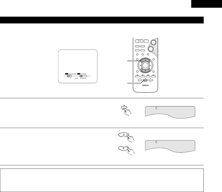
81
ENGLISH
(8) Using the Multiple Audio, Subtitle and Angle Functions
[1] Switching the Audio Language (Multiple Audio Function)
2With DVDs containing multiple audio language signals, the audio language can be switched during playback.
1
2
During playback, press the AUDIO button.
• The current audio language number is displayed.
Use the •and ªcursor buttons to select the desired
language.
• The display turns off when the AUDIO button is pressed.
Remote control unit
AUDIO
Remote control unit
NOTES:
• With some discs it is not possible to change the audio language during playback. In such cases, select from the DVD menu. (See page
96.)
• If the desired language is not set after pressing the •and ªcursor buttons several times, the disc does not include that language.
• The language selected in the default settings is set when the power is turned on and when the disc is replaced.
AUDIO 2/3:DOLBY D3/2/.1 FRA
AUDIO 1/3:DOLBY D3/2/.1 ENG
RC-966
3
STAT US
RETURN
ANGLE AUDIO
SUB TITLE
SETUP TONE /SDB
DVD
ENTER
MUTING
DISPLAY MENU
TOP MENU
CDR TAPE
SURROUND
PARAMETER
CH SELECT
-
+
VCR CH
9
8
21
76
+
-
1
2
A / V
SYSTEM MD
CDR TAPE
TUNER TV / VCR
IN/SURR.
IN/SURR.
DVD
Set the remote
control selector
switches to A/V
and DVD.

ENGLISH
82
[2] Switching the Subtitle Language (Multiple Subtitle Function)
2With DVDs containing multiple subtitle language signals, the subtitle language can be switched during playback.
1
2
During playback, press the SUBTITLE button.
• The current subtitle language number is displayed.
Use the •and ªcursor buttons to select the desired
language.
• The display turns off when the SUBTITLE button is
pressed.
Remote control unit
SUB TITLE
Remote control unit
NOTES:
• If the desired language is not set after pressing the •and ªcursor buttons several times, the disc does not include that language.
• The subtitle language set with the default settings is set when the power is turned on and when the disc is replaced. If that language is
not included on the disc, the disc’s default language is set.
• When the subtitle language is changed, several seconds may be required for the new language to appear.
• When a disc supporting the closed caption is played, the subtitle and the closed caption may overlap each other on the TV monitor. In
this case, turn the subtitle off.
SUBTITLE 02/03:FRA
SUBTITLE 01/03:ENG
RC-966
3
STAT US
RETURN
ANGLE AUDIO
SUB TITLE
SETUP TONE /SDB
DVD
ENTER
MUTING
DISPLAY MENU
TOP MENU
CDR TAPE
SURROUND
PARAMETER
CH SELECT
-
+
VCR CH
9
8
21
76
+
-
1
2
A / V
SYSTEM MD
CDR TAPE
TUNER TV / VCR
IN/SURR.
IN/SURR.
DVD
Set the remote
control selector
switches to A/V
and DVD.

83
ENGLISH
[3] Switching the Angle (Multiple Angle Function)
2With DVDs containing multiple angle signals, the angle can be switched during playback.
1
2
During playback, press the ANGLE button.
• The current angle number is displayed.
Use the •and ªcursor buttons to select the desired angle.
• The display turns off when the ANGLE button is pressed.
3/5
NOTES:
•The multiple angle function only works with discs on which multiple angles are recorded.
•At scenes where multiple angles are recorded, the angle can be switched.
ANGLE
Remote control unit
Remote control unit
4/5
RC-966
3
STAT US
RETURN
ANGLE AUDIO
SUB TITLE
SETUP TONE /SDB
DVD
ENTER
MUTING
DISPLAY MENU
TOP MENU
CDR TAPE
SURROUND
PARAMETER
CH SELECT
-
+
VCR CH
9
8
21
76
+
-
1
2
A / V
SYSTEM MD
CDR TAPE
TUNER TV / VCR
IN/SURR.
IN/SURR.
DVD
Set the remote
control selector
switches to A/V
and DVD.

ENGLISH
84
(9) Using the Menus
[1] Using the Top Menu
2For DVDs containing multiple titles, the desired title can be selected and played from the top menu.
1
2
During playback, press the TOP MENU button.
•The top menu appears.
Use the cursor or number buttons to select the desired title.
•If you select the title number using the number buttons, skip step
3 below.
Press the ENTER button.
•Playback starts.
•Playback also starts if the PLAY (1) button is pressed.
3
Example:
Example:
When “Orange” is selected
Banana
Strawberry
Pineapple
TOP MENU
Orange
Peach
Apple
Banana
Strawberry
Pineapple
TOP MENU
Orange
Peach
Apple
Remote control unit
Remote control unit
ENTER
TOP MENU
Remote control unit
Remote control unit
321
654
987
0/10 +10
TUNERDVD
MD/ LINE-1 TAPE/ LINE-2
AUTO DECODE
VIRTUAL
5CH STEREO
STEREO
D.AUX
+
-
+
-
A / V
A-B REPEAT
SEARCH MODE
ONOFF
REPEAT RANDOM
CLEAR ZOOMSLIDE MODE
PROG/ DIRECT
MEMO BANDMODE
FUNCTIONSURROUNDINPUT MODETEST TONE
DVD
TUNER
CH
3
-
+
21
654
987
0/10
CALL
+10
SYSTEM MD
CDR TAPE
TUNER TV / VCR
VCR
NTSC/PAL
SLEEP
ENTER EDIT/MENUCHARAC.
REC
TIMETITLE
TUNING /
TV VOL
TV CH TV CH
TUNERDVD
MD/ LINE-1 TAPE/ LINE-2
AUTO DECODE
VIRTUALDIRECT
5CH STEREO
STEREO
D.AUX
IN/SURR.
IN/SURR.
DVD
T VTV INSOURCE
9
8
21 +
CD SRS
RTCT
PTYRDS
2
RC-966
3
STAT US
RETURN
ANGLE AUDIO
SUB TITLE
SETUP TONE /SDB
DVD
ENTER
MUTING
DISPLAY MENU
TOP MENU
CDR TAPE
SURROUND
PARAMETER
CH SELECT
-
+
VCR CH
9
8
21
76
+
-
1
2
3
A / V
SYSTEM MD
CDR TAPE
TUNER TV / VCR
IN/SURR.
IN/SURR.
DVD
Set the remote
control selector
switches to A/V
and DVD.

85
ENGLISH
[2] Using the DVD Menu
2Some DVDs include special menus called DVD menus.
For example, DVDs with complex contents may contain guide menus, and DVDs with multiple languages may contain audio and subtitle
language menus.
These menus are called “DVD menus”.
Here we describe the general procedure for using DVD menus.
1
2
During playback, press the MENU button.
•The DVD menu appears.
Use the cursor or number buttons to select the desired item.
•If you select the item using the number buttons, skip step 3
below.
Press the ENTER button.
•The selected item is set.
•If more menus appear, repeat steps 2 and 3.
3
Example:
Example:
“AUDIO” is selected
Remote control unit
ENTER
2. AUDIO
3. ANGLE
1. SUB TITLE
2. AUDIO
3. ANGLE
1. SUB TITLE
DVD MENU
DVD MENU
MENU
Remote control unit
Remote control unit
Remote control unit
321
654
987
0/10 +10
TUNERDVD
MD/ LINE-1 TAPE/ LINE-2
AUTO DECODE
VIRTUAL
5CH STEREO
STEREO
D.AUX
+
-
+
-
A / V
A-B REPEAT
SEARCH MODE
ONOFF
REPEAT RANDOM
CLEAR ZOOMSLIDE MODE
PROG/ DIRECT
MEMO BANDMODE
FUNCTIONSURROUNDINPUT MODETEST TONE
DVD
TUNER
CH
3
-
+
21
654
987
0/10
CALL
+10
SYSTEM MD
CDR TAPE
TUNER TV / VCR
VCR
NTSC/PAL
SLEEP
ENTER EDIT/MENUCHARAC.
REC
TIMETITLE
TUNING /
TV VOL
TV CH TV CH
TUNERDVD
MD/ LINE-1 TAPE/ LINE-2
AUTO DECODE
VIRTUALDIRECT
5CH STEREO
STEREO
D.AUX
IN/SURR.
IN/SURR.
DVD
T VTV INSOURCE
9
8
21 +
CD SRS
RTCT
PTYRDS
2
RC-966
3
STAT US
RETURN
ANGLE AUDIO
SUB TITLE
SETUP TONE /SDB
DVD
ENTER
MUTING
DISPLAY MENU
TOP MENU
CDR TAPE
SURROUND
PARAMETER
CH SELECT
-
+
VCR CH
9
8
21
76
+
-
1
2
3
A / V
SYSTEM MD
CDR TAPE
TUNER TV / VCR
IN/SURR.
IN/SURR.
DVD
Set the remote
control selector
switches to A/V
and DVD.

ENGLISH
86
NOTES:
•Zooming is not possible with some discs.
•The zoom function may not work properly at some scenes.
•Zooming is not possible at the top menu or the menu screen.
In the play or pause mode, press the ZOOM button.
•The zoom rate increases each time the ZOOM button is pressed.
For DVD video discs and video CDs:
OFF Æx1.5 Æx2 Æx4 ÆOFF
ZOOM
+
EDIT/MENU
TV CH
Remote control unit
Use the cursor buttons (ª, •, 0and 1) to move the zoomed
picture.
Remote control unit
(10) Playing in the zoom mode
1
2
+
-
+
-
A / V
A-B REPEAT
SEARCH MODE
ONOFF
REPEAT RANDOM
CLEAR ZOOMSLIDE MODE
PROG/ DIRECT
MEMO BANDMODE
FUNCTIONSURROUNDINPUT MODETEST TONE
DVD
TUNER
CH
3
-
+
21
654
987
0/10
CALL
+10
SYSTEM MD
CDR TAPE
TUNER TV / VCR
VCR
NTSC/PAL
SLEEP
ENTER EDIT/MENUCHARAC.
REC
TIMETITLE
TUNING /
TV VOL
TV CH TV CH
TUNERDVD
MD/ LINE-1 TAPE/ LINE-2
AUTO DECODE
VIRTUALDIRECT
5CH STEREO
STEREO
D.AUX
IN/SURR.
IN/SURR.
DVD
T VTV INSOURCE
9
8
21 +
CD SRS
RTCT
PTYRDS
1
RC-966
3
STAT US
RETURN
ANGLE AUDIO
SUB TITLE
SETUP TONE /SDB
DVD
ENTER
MUTING
DISPLAY MENU
TOP MENU
CDR TAPE
SURROUND
PARAMETER
CH SELECT
-
+
VCR CH
9
8
21
76
+
-
2
A / V
SYSTEM MD
CDR TAPE
TUNER TV / VCR
IN/SURR.
IN/SURR.
DVD
Set the remote
control selector
switches to A/V
and DVD.

87
ENGLISH
(1) Setting the clock (24-hour display)
18
USING THE TIMER
1Turn on the power.
2Press the MENU/SET button to display “Time”.
MENU/SET
Main unit
•If the time has not yet been set or if there has been a
power shortage, the time display flashes.
•If the time has been set, the current time is displayed.
3Press the MENU/SET button and hold it in for over 2 seconds.
•The hours position flashes.
Time 0:00
Adj 0:00
MENU/SET
Main unit
Example: Setting the current time to “19:30”
6Turn the SURROUND/SELECT knob to move to the minutes
position.
Adj 19:30
SURROUND/ SELECT
PUSH
-
PARAM.
Main unit
7Press the MENU/SET button at the sound of a time signal,
etc.
•The “30” in the minutes place stops flashing and the
current time is displayed.
Time 19:30
MENU/SET
Main unit
To check the current time when the regular display is displayed,
press the MENU/SET button once. The current time remains
displayed until some other operation is performed.
The time can be displayed by pressing the MENU/SET button
when the power is in the standby mode. (When this is done, the
set is no longer in the low power consumption standby mode.)
When pressed twice while the time is displayed, the display turns
off and the set is put back in the low power consumption standby
mode.
The current time can also be set when the power is in the standby
mode by pressing the MENU/SET button to display the time then
performing steps 3to 7.
The clock runs by synchronizing with the power supply frequency.
The time may be off by 2 to 3 minutes per month. If so, reset the
time.
B
BAND
PHONES
VOLUME
ON / STANDBY
DVD SURROUND RECEIVER ADV-M71
TONE/SDB
FUNCTION
MENU/SET +
-
SURROUND/SELECT
PUSH
-
PARAM.
1
4,6 2,3,5,7
2Timer and system operations are possible once the setup procedure has been completed.
4Turn the SURROUND/SELECT knob to set the hours.
Adj 19:00
SURROUND/ SELECT
PUSH
-
PARAM.
Main unit
5Press the MENU/SET button.
MENU/SET
Main unit
Adj 19:00
2Be sure to set the current time. If the current time is not set, the timer standby indicator does not light and the timer will not function.
2Be sure to preset the broadcast station before setting the timer. (See page 64.)
2Everyday timer: The power is switched on and off (standby) once at the same time each day.
Once timer: The power is switched on and off (standby) at the specified time once only.
Sleep timer: The power can be set to turn off in 120 minutes, 90 minutes, or between 60 and 10 minutes in 10 minute steps.
2If the times set for the everyday timer, once timer and sleep timer overlap, the sleep timer has priority. The once time has priority if the everyday
timer and once timer times overlap.
2It is not possible to set the timer start and stop times to the same time.
ON / STANDBY
Main unit
Before setting the timer

ENGLISH
88
Example 1: Listening to preset station “3” (FM 92.5 MHz) from 12:35 to 12:56 with the everyday timer
B
BAND
PHONES
VOLUME
ON / STANDBY
DVD SURROUND RECEIVER ADV-M71
TONE/SDB
FUNCTION
MENU/SET +
-
SURROUND/SELECT
PUSH
-
PARAM.
1,18
2,3,4,6,8,
10,12,14,16
3,5,7,9,11,
13,15,17
(2) Setting the everyday timer and once timer
2Be sure to set the current time before setting the timer. (See page 87.)
2Use the everyday timer to switch the power on and off (standby) once at the same time each day.
Use the once timer to switch the power on and off (standby) at the specified time once only.
2With the ADV-M71 it is possible to play the tuner, a DVD or a CD with the timer.
2It is possible to play a DVD, CD, tape, the tuner, MD or the device connected to the AUX terminals with the timer and to record the tuner or
the device connected to the AUX terminals onto an MD recorder or cassette deck using the timer.
Timer playback is not possible for some DVDs. (Most DVDs stop at the menu screen.)
1Turn on the power.
2Press the MENU/SET button to display “TIMER”.
MENU/SET
Main unit
3Turn the SURROUND/SELECT knob to display “EVERYDAY”,
then press the MENU/SET button.
•The display switches as follows
each time the SURROUND/SELECT
knob is turned:
TIMER
EVERYDAY
SURROUND/ SELECT
PUSH
-
PARAM.
Main unit
4Press the MENU/SET button.
E FUNC
MENU/SET
Main unit
ON / STANDBY
Main unit
The display switches as follows
each time the
SURROUND/SELECT knob is
turned:
MENU/SET
Main unit
5Turn the SURROUND/SELECT knob and set the function to
“TUNER”.
SURROUND/ SELECT
PUSH
-
PARAM.
Main unit
E TUNER
The function switches as shown below each time the
surround button is pressed.
Functions marked “*” differ according to whether “LINE-
1” or “LINE-2” is set.
DVD TUNER (LINE1)
(LINE2)
(LINE1)
TU
AUX (LINE1 2)
TU (LINE2)
*
*
*
**
:Clockwise turn
:Counterclockwise turn
6Press the MENU/SET button.
MENU/SET
Main unit
7Turn the SURROUND/SELECT knob and select preset number
“P03”.
P03 FM 92.50M
SURROUND/ SELECT
PUSH
-
PARAM.
Main unit
8Press the MENU/SET button.
•The data for the selected station is stored in the memory
and the unit is set to the timer start time setting mode.
•“E” and “on” are displayed.
Eon 0:00
MENU/SET
Main unit
9<Setting the timer start time>
Turn the SURROUND/SELECT knob to set the hours place to
“12”.
Eon 12:00
SURROUND/ SELECT
PUSH
-
PARAM.
Main unit
ONCE EVERYDAY
or

89
ENGLISH
10 Press the MENU/SET button.
•The “12” in the hours place is stored in the memory.
MENU/SET
Main unit
Eon 12:00
11 Turn the SURROUND/SELECT knob and set the minutes
place to “35”.
Eon 12:35
SURROUND/ SELECT
PUSH
-
PARAM.
12 Press the MENU/SET button.
•The start time is stored in the memory and the unit is set
to the timer stop time setting mode.
•“E” and “off” light.
Main unit
MENU/SET
Main unit
Eoff 0:00
13 <Setting the timer stop time>
Turn the SURROUND/SELECT knob to set the hours place to
“12”.
Eoff 12:00
SURROUND/ SELECT
PUSH
-
PARAM.
Main unit
14 Press the MENU/SET button.
•The “12” in the hours place is stored in the memory.
MENU/SET
Main unit
Eoff 12:00
15 Turn the SURROUND/SELECT knob and set the minutes
place to “56”.
Eoff 12:56
SURROUND/ SELECT
PUSH
-
PARAM.
Main unit
16 Press the MENU/SET button.
•The stop time is stored in the memory.
MENU/SET
Main unit
17 Turn the SURROUND/SELECT knob to display “Eon”.
•The everyday timer is turned on and
the timer standby indicator
lights. This completes the setting of
the timer.
For more details, see “Turning the
everyday timer and once timer on
and off” on page 88.
SURROUND/ SELECT
PUSH
-
PARAM.
Main unit
1 off/E on
18
ON / STANDBY
Main unit
Turn off the power.
•The standby mode is set.
(The power indicator turns orange.)
•When the timer start time is
reached, the timer operates.
If you make a mistake when setting the
timer
•Press the stop button at any point
between steps 4 and 15. (The display
returns to as it was in step 3.)
•Press the MENU/SET button repeatedly
to display the item you want to correct,
then correct the item.
•After correcting the item, press the MENU/SET button again
repeatedly to proceed to step 18 and complete the setting of the
timer.
NOTE:
•The timer standby indicator does not light if the current time
has not been set. Set the current time before setting the timer.
(See page 87.)
BAND
Main unit

ENGLISH
90
Example 2: Listening to a CD with the once timer
B
BAND
PHONES
VOLUME
ON / STANDBY
DVD SURROUND RECEIVER ADV-M71
TONE/SDB
FUNCTION
MENU/SET +
-
SURROUND/SELECT
PUSH
-
PARAM.
13,4,5,7
4,6 22
1Turn on the power.
ON / STANDBY
Main unit
4Turn the SURROUND/SELECT knob to display “ONCE”, then
press the MENU/SET button.
SURROUND/ SELECT
PUSH
-
PARAM.
Main unit
ONCE
The display switches as follows
each time the
SURROUND/SELECT knob is
turned:
2Open the disc holder, load the CD,
then close the disc holder.
Main unit
3Press the MENU/SET button to
display “TIMER”.
MENU/SET
Main unit
TIMER
5Press the MENU/SET button.
•The once timer time setting mode is set.
•“1” (once) lights.
1 FUNC
MENU/SET
Main unit
6Turn the SURROUND/SELECT knob and set the function to
“DVD”.
1DVD
SURROUND/ SELECT
PUSH
-
PARAM.
Main unit
7Press the MENU/SET button.
•Timer function, “DVD”, is stored in
the memory.
MENU/SET
Main unit
8Now follow steps 9 to 18 under “Setting the everyday timer
and once timer” (pages 88 and 89).
•“1” and “on” light when setting the start time.
“1” and “off” light when setting the stop time.
•Turn the once timer on at step 17.
2Timer playback and recording can be performed when system connections are made between the ADV-M71 and the D-M31 series MD recorder
(DMD-M31) or cassette deck (DRR-M31). (Both the everyday and once timer can be used.)
•Timer playback of the cassette deck (when TAPE is set for LINE-2)
•Timer playback of the MD recorder (when MD is set for LINE-1 or LINE-2)
•Timer playback of the device connected to the AUX input terminals (when AUX is set for LINE-1 or LINE-2)
•Timer recording of radio programs from the ADV-M71 onto the cassette deck (when TAPE is set for LINE-1)
•Timer recording of radio programs from the ADV-M71 onto the MD recorder (when MD is set for LINE-1)
•Timer recording from the device connected to the AUX input terminals onto the cassette deck (when AUX is set for LINE-1 and TAPE is set
for LINE-2)
•Timer recording from the device connected to the AUX input terminals onto the MD recorder (when AUX and MD are set for LINE-1 and
LINE-2)
Timer recording onto the device connected to the AUX input terminals is not possible. The timer function changes automatically according
to the function set for LINE-1 and LINE-2.
NOTE:
•For timer recording and playback using the device connected to the AUX input terminals, note that the ADV-M71 cannot control the power
of the device or playback operations on it. Make the settings accordingly.
ONCE EVERYDAY
MENU/SET
Main unit

91
ENGLISH
(3) Turning the everyday timer and once timer on and off
•After the timer has been set using the procedure described under “(2) Setting the everyday timer and once timer” (pages 88 to 89), turn the
everyday timer and/or once timer on so that the set operations will be performed.
B
BAND
PHONES
VOLUME
ON / STANDBY
DVD SURROUND RECEIVER ADV-M71
TONE/SDB
FUNCTION
MENU/SET +
-
SURROUND/SELECT
PUSH
-
PARAM.
1
2
1Press the MENU/SET button to set the timer standby setting
mode.
•The current settings are displayed.
MENU/SET
Main unit
1 on/E on
2Turn the SURROUND/SELECT knob and select the timer to be
operated.
•The display switches as follows
each time the
SURROUND/SELECT knob is
turned:
1 on/E on
1 on/E off
1 off/E on
1 off/E off
Both the once timer and everyday
timer are activated.
Only the everyday timer is activated.
Only the once timer is activated.
•When either the once or everyday timer is activated, the
timer standby indicator lights. The display returns to
normal about 4 seconds after the timer standby indicator
is displayed.
SURROUND/ SELECT
PUSH
-
PARAM.
Main unit
The timer operation is performed when the SURROUND/SELECT
knob has been turned and the timer standby indicator has
been lit.
SURROUND/ SELECT
PUSH
-
PARAM.
Main unit
NOTES:
•The timer standby indicator does not light if the current time
has not been set. Set the current time before setting the timer.
(See page 87.)
•If the times set for the everyday timer and once timer overlap,
the once time has priority.
•Be sure to set the power to the standby mode when you want
the timer to operate.
Neither the once timer nor the
everyday timer are activated.
If you do not want the timer to operate,
turn the SURROUND/SELECT knob to turn
the timer standby indicator off.
•If only the once timer is set, the setting
changes as shown below each time the
SURROUND/SELECT knob is turned.
SURROUND/ SELECT
PUSH
-
PARAM.
Main unit
1on/E off f1off/E of
•If only the everyday timer is set, the setting changes as follows:
1off/E on f1off/E of

ENGLISH
92
•If the times set for the everyday timer and once timer overlap, the once time has priority.
(4) Everyday timer and once timer priority
2Checking the timer settings
•Use the same procedure as when setting the timer to check the timer settings.
qPress the MENU/SET button to display “TIMER”.
wTurn the SURROUND/SELECT knob to display “EVERYDAY” or “ONCE”.
eThe display switches between the set function, start time, stop time and timer standby indicator each time the MENU/SET button is pressed.
rThe display returns to as it was before the everyday timer or once timer was set about 4 seconds after the timer standby indicator is
displayed.
2Changing the timer settings
•Reset the timer from the start using the desired settings.
The new settings overwrite the previous settings.
•To change a setting during the process of setting the timer, press the stop button (2) to return to the “EVERYDAY” or “ONCE” display, then
redo the operation from there.
2Clearing the timer settings
qPress the MENU/SET button to display “TIMER”.
wTurn the SURROUND/SELECT knob to display “EVERYDAY” or “ONCE” (the timer whose settings you want to clear).
eWhile “EVERYDAY” or “ONCE” is displayed, press the stop button (2) and hold it in for at least 2 seconds. Those timer settings are cleared.
2Quitting the timer setting (turning the operation of the timer off)
•Operate as described under “(3) Turning the everyday timer and once timer on and off” (page 88) and change the setting to the mode in
which neither the once timer nor the everyday timer are activated (“1off/Eoff”).
2If there is a power failure)
•If there is a power failure or the power cord is unplugged from the power outlet, the time display flashes when the power comes back on.
Reset the current time.
•The once timer settings are deleted. Remake the settings.
•If the everyday timer settings and the tuner presettings have been deleted, reset them.
(5) About the everyday timer and once timer

93
ENGLISH
•The included remote control unit can be used to turn the power to the standby mode after a maximum of 120 minutes. (Sleep timer)
•Use this function to automatically switch the power to the standby mode after a specific amount of time (minutes).
Example: To set the power to the standby mode in 50 minutesaccording to the clock. Be sure to correct the current time setting.
(6) Setting the sleep timer (remote control unit only)
1Select and play the desired function.
2Press the SLEEP button.
•“120” is displayed and the “SLEEP” indicator flashes.
SLEEP
SOURCE
Remote control unit
120
SLEEP
The display switches as follows each time the SLEEP
button is pressed:
90120 60 50 3040 20 10
3When the “SLEEP” indicator is flashing, press the SLEEP
button again until “50” is displayed.
•“50” is displayed and the “SLEEP” indicator flashes.
SLEEP
SOURCE
Remote control unit
50
SLEEP
•After 4 seconds, the display returns to as it was before the
sleep timer was set, and the “SLEEP” indicator stops
flashing, remaining lit. (This completes the sleep timer
setting.)
4The power is set to the standby mode 50 minutes later.
To turn the sleep timer off, press the SLEEP button repeatedly until
the “SLEEP” indicator turns off. The sleep timer can also be
turned off by press the power button on the main unit or the
remote control unit to turn the entire system’s power to the
standby mode.
NOTES:
•If the SLEEP button is pressed while the sleep timer is
operating, the setting returns to 120 minutes. Make the setting
over.
•If the sleep timer and everyday timer settings overlap, the sleep
timer has priority.
20:00 21:00 22:00
20:00 21:00 22:00
ON OFF
ON OFF
+
ON OFF
20:00 21:00 22:00
ON OFF
ON OFF
+
•Also, the everyday timer will not operate if its start time is set
within the time during which the sleep timer is operating.
“SLEEP” indicator off
Everyday timer
once timer setting
Sleep timer
setting
Timer operation
If the timers overlap like this, the timer operates as follows:
Everyday timer
once timer setting
Sleep timer
setting
Does not operate
•The remaining time of the sleep timer can be checked with the
STATUS button.
Does not operate
ON / STANDBY
OFF
Main unit Remote control unit
SLEEP
SOURCE
Remote control unit
+
-
+
-
A-B REPEAT
SEARCH MODE
ONOFF
REPEAT RANDOM
CLEAR ZOOMSLIDE MODE
PROG/ DIRECT
MEMO BANDMODE
FUNCTIONSURROUNDINPUT MODETEST TONE
TUNER
CH
3
-
+
21
654
987
0/10
CALL
+10
VCR
NTSC/PAL
SLEEP
ENTER EDIT/MENUCHARAC.
REC
TIMETITLE
TUNING /
TV VOL
TV CH TV CH
TUNERDVD
MD/ LINE-1 TAPE/ LINE-2
AUTO DECODE
VIRTUALDIRECT
5CH STEREO
STEREO
D.AUX
T VTV INSOURCE
CD SRS
RTCT
PTYRDS
2,3
A / V
SYSTEM MD
CDR TAPE
TUNER TV / VCR
IN/SURR.
IN/SURR.
DVD
Set the remote
control selector
switches to A/V
and IN/SURR..

ENGLISH
94
19
CHANGING THE DEFAULT SETTINGS (DVD)
Remote control unit
Remote control unit
ENTER
1
2
In the stop mode, press the SETUP button.
At the Setup Menu, use the •and ªcursor buttons to select
“DVD SETUP” and press the ENTER button.
The setup (default settings) screen “DVD SETUP MENU”
appears.
•DISC SETUP
Use this to set the language to be used when playing the
disc.
If the set language is not offered on that disc, the discs
default language is set.
•OSD SETUP
Use this to set the wall paper color.
•VIDEO SETUP
Use this to set this unit screen mode.
(TV aspect and TV type.)
•AUDIO SETUP
Use this to set this unit audio output mode.
(Digital and LPCM output settings.)
•RATINGS
Use this to disable playback of adult DVDs so that children
cannot watch them. Note that playback of adult DVDs
cannot be disabled if the rating level is not recorded on the
DVD, but that it is possible to disable playback of all DVDs.
•OTHER SETUP
Closed captions (subtitles) and the time interval for playing
still pictures can be set.
Use the 0and 1cursor buttons to select the desired setting
item, then press the ENTER button.
To exit the DVD setup mode
Use the 0and 1cursor buttons to select “EXIT SETUP”, then press the ENTER button. It is also possible to quit by pressing the SETUP
button on the remote control unit.
ENTER
SETUP
2The initial setting that was set prior to shipping from the factory can be changed.
The setting contents are maintained until they are next changed even when the power is switched off.
d
Remote control unit
d
Remote control unit
d
Remote control unit

95
ENGLISH
Use the 0and 1cursor buttons to select the “DISC
SETUP”, then press the ENTER button.
•DIALOG
Use this to set the language of the sound output from
the speakers.
•SUBTITLE
Use this to set the language of the subtitles displayed on
the TV.
•DISC MENUS
Use this to set the language of the menus recorded on
the disc (top menu, etc.).
To exit the disc setup mode
Use the •and ªcursor buttons to select “> NEXT DVD
MENU”, then press the ENTER button.
Use the •and ªcursor buttons to select the desired
setting, then press the ENTER button.
2When “DIALOG” is selected:
•ENGLISH (Factory default)
Select this when you want to play the DVD with the
sound in English.
•FRENCH
Select this when you want to play the DVD with the
sound in French.
•SPANISH
Select this when you want to play the DVD with the
sound in Spanish.
•GERMAN
Select this when you want to play the DVD with the
sound in German.
•JAPANESE
Select this when you want to play the DVD with the
sound in Japanese.
•OTHERS
The sound is played in the language input with the number
buttons. (See the table of language numbers on page 97.)
Remote control unit
Remote control unit
ENTER
(1) “DISC SETUP” is selected
1
See page 94.
2
3
4
d
Remote control unit
Remote control unit
ENTER
d
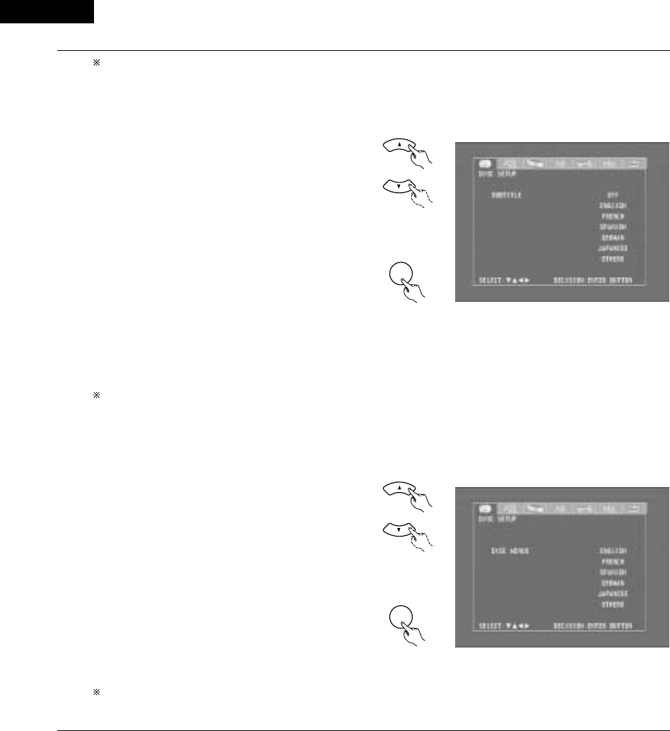
ENGLISH
96
To exit the dialog mode
Press the ENTER button, you can go back to the previous
screen.
2When “SUBTITLE” is selected:
•OFF
Select this if you do not want to display the subtitles. (For
some discs it is not possible to turn off the subtitle
display.)
•ENGLISH (Factory default)
Select this when you want to play the DVD with the
subtitles in English.
•FRENCH
Select this when you want to play the DVD with the
subtitles in French.
•SPANISH
Select this when you want to play the DVD with the
subtitles in Spanish.
•GERMAN
Select this when you want to play the DVD with the
subtitles in German.
•JAPANESE
Select this when you want to play the DVD with the
subtitles in Japanese.
•OTHERS
Subtitles are played in the language input with the number
buttons. (See the table of language numbers on page 97.)
To exit the subtitle mode
Press the ENTER button, you can go back to the previous
screen.
2When “DISC MENUS” is selected:
•ENGLISH (Factory default)
Select this when you want to display the menus in
English.
•FRENCH
Select this when you want to display the menus in
French.
•SPANISH
Select this when you want to display the menus in
Spanish.
•GERMAN
Select this when you want to display the menus in
German.
•JAPANESE
Select this when you want to display the menus in
Japanese.
•OTHERS
The menu screen is played in the language input with the
number buttons.
(See the table of language numbers on page 97.)
To exit the disc menus mode
Press the ENTER button, you can go back to the previous
screen.
4
Remote control unit
Remote control unit
ENTER
d
Remote control unit
Remote control unit
ENTER
d

97
ENGLISH
Language code list
Code
6565
6566
6570
6577
6582
6583
6588
6590
6665
6669
6671
6672
6678
6679
6682
6765
6779
6783
6789
6865
6869
6890
6976
6978
6979
6983
6984
6985
7065
7073
7074
Code
7079
7082
7089
7165
7168
7176
7178
7185
7265
7273
7282
7285
7289
7365
7378
7383
7384
7387
7465
7473
7487
7565
7575
7576
7577
7578
7579
7583
7585
7589
7665
Code
7678
7679
7684
7686
7771
7773
7775
7776
7778
7779
7782
7783
7784
7789
7865
7869
7876
7879
7982
8065
8076
8083
8084
8185
8277
8279
8285
8365
8368
8372
8373
Language
Afar
Abkhazian
Afrikaans
Ameharic
Arabic
Assamese
Aymara
Azerbaijani
Bashkir
Byelorussian
Bulgarian
Bihari
Bengali; Bangla
Tibetan
Breton
Catalan
Corsican
Czech
Welsh
Danish
German
Bhutani
Greek
English
Esperanto
Spanish
Estonian
Basque
Persian
Finnish
Fiji
Language
Faroese
French
Frisian
Irish, Scots
Gaelic
Galician
Guarani
Gujarati
Hausa
Hindi
Croatian
Hungarian
Armenian
Interlingua
Indonesian
Icelandic
Italian
Hebrew
Japanese
Yiddish
Javanese
Georgian
Kazakh
Greenlandic
Cambodian
Kannada
Korean
Kashmiri
Kurdish
Kirghiz
Latin
Language
Lingala
Laothian
Lithuanian
Latvian, Lettish
Malagasy
Maori
Macedonish
Malayalam
Mongolian
Moldavian
Marathi
Malay
Maltese
Burmese
Nauru
Nepali
Dutch
Norwegian
Oriya
Panjabi
Polish
Pashto, Pushto
Portuguese
Quechua
Rhaeto-Romance
Romanian
Russian
Sanskrit
Sindhi
Serbo-Croatian
Singhalese
Code
8375
8376
8377
8378
8379
8381
8382
8385
8386
8387
8465
8469
8471
8472
8473
8475
8476
8479
8482
8484
8487
8575
8582
8590
8673
8679
8779
8872
8979
9072
9085
Language
Slovak
Slovenian
Samoan
Shona
Somali
Albanian
Serbian
Sundanese
Swedish
Swahili
Tamil
Telugu
Tajik
Thai
Tigrinya
Turkmen
Tagalog
Tonga
Turkish
Tatar
Twi
Ukrainian
Urdu
Uzbek
Vietnamese
Volapük
Wolof
Xhosa
Yoruba
Chinese
Zulu
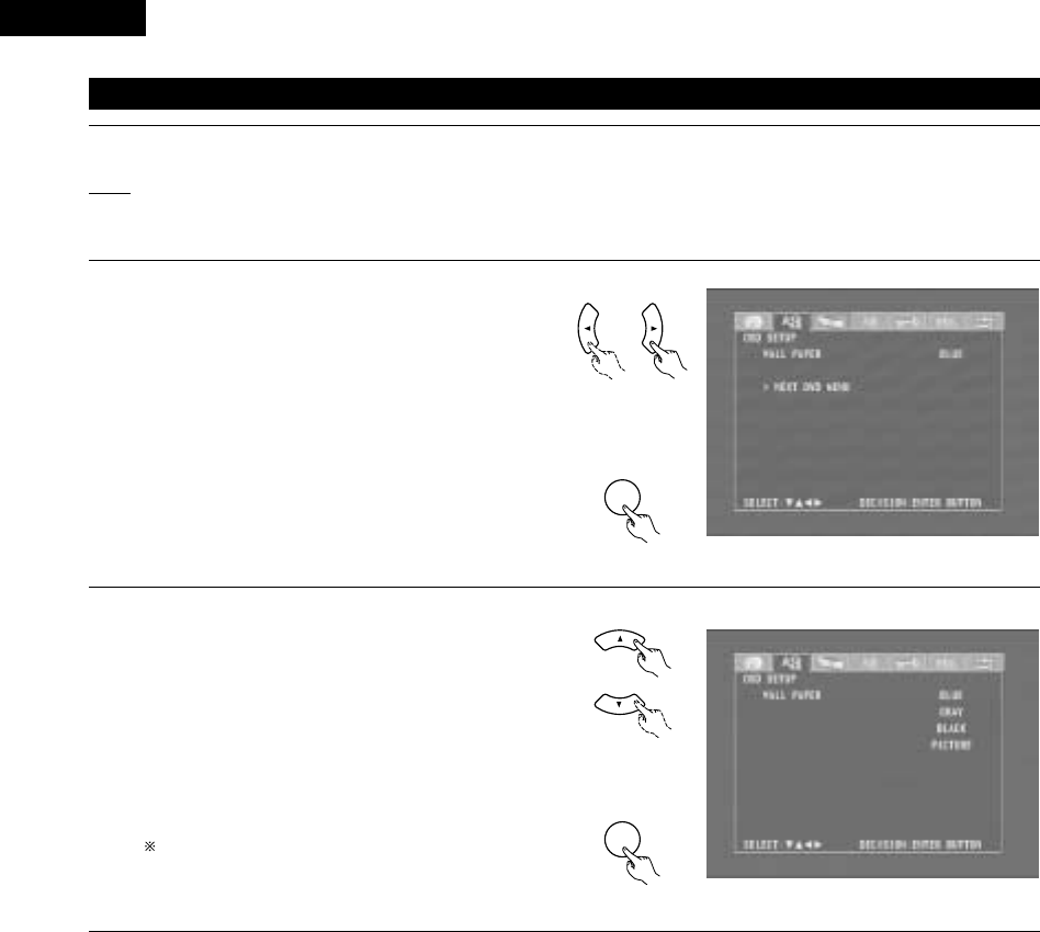
ENGLISH
98
(2) When “OSD SETUP” is selected
Use the 0and 1cursor buttons to select the “OSD
SETUP” tag icon, then press the ENTER button.
•WALL PAPER
The image displayed when in the stop mode or when
playing a CD can be selected.
1
If you are not at the DVD setting screen, read steps 1 and 2 on page 94.
2
3
4
Remote control unit
Remote control unit
ENTER
d
Use the •and ªcursor buttons to select the setting to be
set, then press the ENTER button.
2When “WALL PAPER” has been selected
•Use the •and ªcursor buttons to select the wallpaper.
•BLUE (Factory default)
The wallpaper is set to blue.
•GRAY
The wallpaper is set to gray.
•BLACK
The wallpaper is set to black.
•PICTURE
The wallpaper is set to a picture.
To complete the “WALL PAPER” setting
Press the ENTER button.
Remote control unit
Remote control unit
ENTER
d

99
ENGLISH
(3) “VIDEO SETUP” is selected
Use the 0and 1cursor buttons to select the “VIDEO
SETUP”, then press the ENTER button.
•TV ASPECT
Use this to set the shape of your TV’s screen.
•TV TYPE
Use this to set your TV’s video format (NTSC, PAL or
MULTI).
•BLACK LEVEL
The picture’s black level can be set to “lighter” or
“darker”.
To exit the video setup mode
Use the •and ªcursor buttons to select “> NEXT DVD
MENU”, then press the ENTER button.
1
See page 94.
2
3
Use the •and ªcursor buttons to select the desired
setting, then press the ENTER button.
2When “TV ASPECT” is selected:
•4:3 PS (Factory default)
Select this to play wide DVDs in the pan & scan mode
(with the sides of the picture cut off). Discs for which pan
& scan is not specified are played in the letter box mode.
•4:3 LB
Select this to play wide DVDs in the letter box mode (with
black strips at the top and bottom).
•WIDE (16:9)
Select this to play wide DVDs in the full-screen mode.
To exit the TV aspect mode
Press the ENTER button, you can go back to the previous
screen.
4
Remote control unit
Remote control unit
ENTER
d
Remote control unit
Remote control unit
ENTER
d

ENGLISH
100
2When “TV TYPE” is selected:
•NTSC
Select this when your TV’s video format is NTSC.
If NTSC is selected, output format is fixed to NTSC.
•PAL (Factory default)
Select this when your TV’s video format is PAL.
If PAL is selected, output format is fixed to PAL.
•MULTI
Select this when your TV is compatible with both the
NTSC and PAL formats.
NTSC signals are output from the video output jacks
when discs recorded in NTSC format are played, and PAL
signals are output from the video output jacks when discs
recorded in PAL format are played.
To exit the TV type mode
Press the ENTER button, you can go back to the previous
screen.
2When “BLACK LEVEL” has been selected
•Use the •and ªcursor buttons to select the black level.
•DARKER (Factory default)
This sets the black level of the output signals to the
standard level.
•LIGHTER
This raises the standard level for the black level. Set this
if the picture displayed on the TV is extremely dark.
To complete the “BLACK LEVEL” setting
Press the ENTER button.
4
Remote control unit
Remote control unit
ENTER
d
Remote control unit
Remote control unit
ENTER
d

101
ENGLISH
(4) “AUDIO SETUP” is selected
3Use the 0and 1cursor buttons to select the “AUDIO
SETUP”, then press the ENTER button.
•DIGITAL OUT
Use this to select the digital output’s signal format.
•LPCM (44.1 kHz / 48 kHz)
Use this to set the digital audio output when playing
DVDs recorded in linear PCM audio.
To exit the audio setup mode
Use the •and ªcursor buttons to select “> NEXT DVD
MENU”, then press the ENTER button.
•The screen returns to as it was in step 2.
Use the •and ªcursor buttons to select the desired
setting, then press the ENTER button.
2When “DIGITAL OUT” is selected.
•NORMAL (Factory default)
Make the selection when playing back in surround
playback a DVD that has been recorded with Dolby Digital
or DTS on this unit.
The Dolby Digital or DTS digital signal is also output from
the digital output jacks.
•PCM
DVDs that were recorded in Dolby Digital DTS are
converted to linear PCM 48 kHz/16 bit (2 channels). Make
the selection when making a digital recording.
To exit the digital out mode
Press the ENTER button, you can go back to the previous
screen.
Remote control unit
Remote control unit
ENTER
Remote control unit
Remote control unit
ENTER
d
d
4
1
See page 94.
2
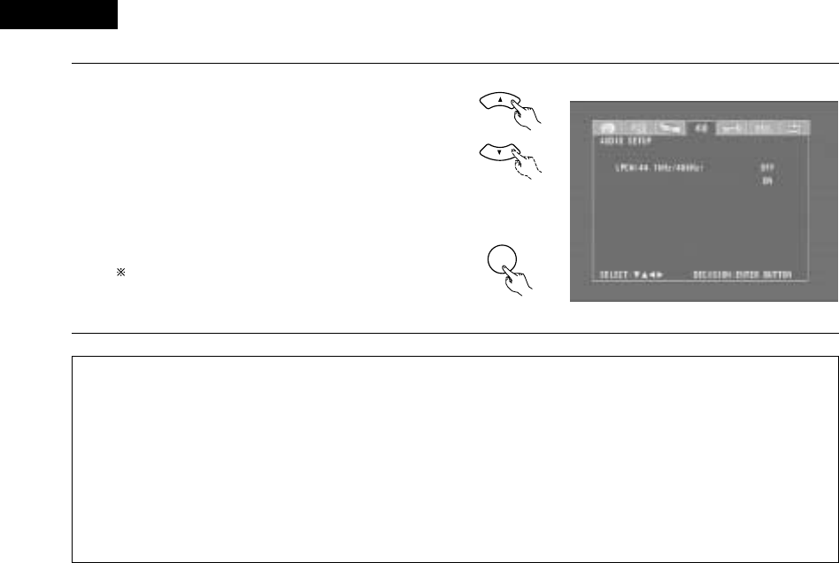
ENGLISH
102
42“LPCM SELECT (96 kHz /48 kHz)” is selected.
•OFF (Factory default)
Make the selection when playing back to a decoder DVDs
that were recorded with this unit using linear PCM 48
kHz/20/24 bit and 96 kHz modes. Note that DVDs with
Copyright Protection are converted to 48 kHz/16 bits and
played back.
The same signal is output from the digital output jacks.
•ON
DVDs that were recorded with linear PCM 48 kHz/20/24
bit and 96 kHz modes are all converted to 48 kHz/16 bits.
Make this selection at the time of digital recording.
To exit the LPCM select mode
Press the ENTER button, you can go back to the previous
screen.
Remote control unit
ENTER
Remote control unit
d
NOTES:
•When playing Dolby Digital/DTS surround DVDs or 96 kHz linear PCM DVDs on the ADV-M71, be sure to set “Digital Output” to “Normal”
and “LPCM Conversion Mode” to “Do Not Convert”.
•When and only when you want to output the signals of the Dolby Digital/DTS surround DVD being played on the ADV-M71 to a digital
PCM device, set “Digital Output” to “PCM Conversion”.
With this setting, DVDs cannot be played on the ADV-M71 in the Dolby Digital/DTS surround mode. (The surround mode is set to the
mode in which PCM 2-channel signals can be played.)
•When and only when you want to make a digital recording of the signals of a 48 kHz/20-bit/24-bit or 96 kHz linear PCM DVD being played
on the ADV-M71 onto a digital recorder, set the “LPCM Conversion” to “Convert”.
With this setting it is not possible to decode and play 48 kHz/20-bit/24-bit or 96 kHz linear PCM signals on the ADV-M71 during recording.
(Decoding and playback is in 48 kHz/16-bit linear PCM format.)
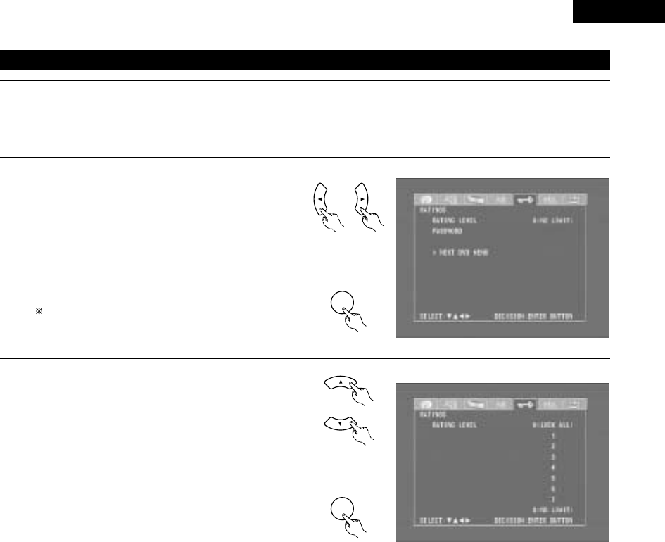
103
ENGLISH
(5) “RATINGS” is selected
3Use the 0and 1cursor buttons to select the “RATINGS”,
then press the ENTER button.
•RATING LEVEL
Use this to restrict playback of adult DVDs you do not
want children to view. Note that even with adult DVDs,
viewing cannot be restricted unless the restriction level is
recorded on the disc.
It is however possible to disable playback of all DVDs.
•PASSWORD
Use this to change the password.
The set’s password is set to “0000” by default.
To exit the rating setup mode
Use the •and ªcursor buttons to select “> NEXT DVD
MENU”, then press the ENTER button.
Remote control unit
ENTER
Remote control unit
4Use the •and ªcursor buttons to select the desired
setting, then press the ENTER button.
2When “RATING LEVEL” is selected.
•Level 0 (LOCK ALL)
Select this to disable playback of all DVDs.
Use this for example to disable playback of adult DVDs on
which the rating level is not recorded.
•Level 1
Select this to play only DVDs for children. (Adult and
general audience DVDs cannot be played.)
•Level 2 to Level 7
Select this to play DVDs for general audiences and
children. Adult DVDs cannot be played.
•NO LIMIT (Factory default)
Select this to play all DVDs.
Remote control unit
ENTER
d
Remote control unit
d
1
See page 94.
2

ENGLISH
104
4Use the number buttons to input a 4-digit password,
then press the ENTER button.
Be sure to set the DVD mode using the remote
control mode selector buttons.
The set's password is set to “0000" by default.
Do not forget the password.
The setting cannot be changed without inputting
the correct password.
321
654
987
0/10 +10
TUNERDVD
MD/ LINE-1 TAPE/ LINE-2
AUTO DECODE
VIRTUAL
5CH STEREO
STEREO
D.AUX
Remote control unit
Remote control unit
ENTER
When the password has been forgotten or when a
RATING LEVEL setting change is suspended, press
the ENTER button several times and terminate the
rating setup mode.
2When “PASSWORD CHANGE” is selected.
Use the number buttons to input a 4-digit
password, then press the ENTER button.
Be sure to set the DVD mode using the remote
control mode selector buttons.
Do not forget the password.
The setting cannot be changed without
inputting the correct password.
The set’s password is set to “0000” by default.
d
321
654
987
0/10 +10
TUNERDVD
MD/ LINE-1 TAPE/ LINE-2
AUTO DECODE
VIRTUAL
5CH STEREO
STEREO
D.AUX
Remote control unit

105
ENGLISH
(6) “OTHER SETUP” is selected
1
2
3
See page 94.
Use the 0and 1cursor buttons to select the “OTHER
SETUP”, then press the ENTER button.
•CAPTIONS
Set whether or not to display the closed captions
(subtitles) recorded on the DVD. (A caption decoder
(commercially available) is required to display captions.)
•SLIDE SHOW
Set the time interval for switching to the next still image
(in JPEG format) when playing slides.
To exit the other setup mode
Use the •and ªcursor buttons to select “> NEXT DVD
MENU”, then press the ENTER button.
Remote control unit
Remote control unit
ENTER
NOTES:
•An English caption decoder is required to display English captions.
•DVDs with caption signals are indicated by the , , , mark.
English captions cannot be displayed when playing DVDs which do not contain caption signals.
•The characters in which the captions are displayed (capital letters, small letters, italics, etc.) depend on the DVD and cannot be selected with
this unit.
4Use the •and ªcursor buttons to select the desired
setting, then press the ENTER button.
2When “CAPTIONS” is selected:
•OFF (Factory default)
Select this when you do not want to display the captions
on the screen when playing DVDs containing English
captions.
•ON
Select this to display the captions on the screen when
playing DVDs containing English captions.
To exit the captions mode
Press the ENTER button, you can go back to the previous
screen.
Remote control unit
Remote control unit
ENTER
d
d

107
ENGLISH
2Making system connections between the ADV-M71 and the D-M31 series MD recorder (DMD-M31) or cassette deck (DRR-M31) makes
operation even easier. (For instructions on connections, refer to “Connecting to D-M31 Series System Components” on pages 8 to 9.)
2System functions will not work properly if the input/output function settings are not right for the connected components. Be sure to set the
input/output functions for the components being used. (See page 29.) The setting contents are maintained until they are next changed even
when the power is switched off.
(1) Auto power on function
•When the play/pause button on the main unit ( 1/3) or the DVD play button on the remote control unit ( 1) is pressed while the power is in
the standby mode, the ADV-M71’s power turns on automatically, and if a disc is loaded in the ADV-M71 the disc is played.
B
BAND
PHONES
VOLUME
ON / STANDBY
DVD SURROUND RECEIVER ADV-M71
TONE/SDB
FUNCTION
MENU/SET +
-
SURROUND/SELECT
PUSH
-
PARAM.
1
-
A / V
3
STAT US
SETUP TONE /SDB
FUNCTIONSURROUNDINPUT MODETEST TONE
DVD
CH
0/10
CALL
ENTER
MUTING
+10
SYSTEM MD
CDR TAPE
TUNER TV / VCR
VIRTUALDIRECT STEREO
IN/SURR.
IN/SURR.
DVD
9
8
21
76
+
-
1
1When the ADV-M71 is in the standby mode, the power can be
turned on simply by pressing the play/pause button on the
main unit or the DVD play button on the remote control unit.
If a disc is loaded, playback starts.
The auto power on function also turns the
power on when the disc holder is opened
while the ADV-M71 is in the standby mode.
Main unit
•To listen to a radio program, simply press
one of the tuner preset buttons (“+” or “–”)
on the remote control unit. The power turns
on and a station is tuned in.
•The power on function works in the same
way when system connections are made
with the D-M31 series MD recorder (DMD-
M31) or cassette deck (DRR-M31). For
details, refer to the respective component’s
operating instructions.
+
-
TUNER
CH
Remote control unit
(2) Auto function selection
•At the touch of a button, the function switches automatically to
“DVD” and disc playback begins.
B
BAND
PHONES
VOLUME
ON / STANDBY
DVD SURROUND RECEIVER ADV-M71
TONE/SDB
FUNCTION
MENU/SET +
-
SURROUND/SELECT
PUSH
-
PARAM.
1
1
•To listen to a radio program, simply press
one of the tuner preset buttons (“+” or “–”)
on the remote control unit.
•Auto function selection works in the same
way when system connections are made
with the D-M31 series MD recorder (DMD-
M31) or cassette deck (DRR-M31). For
details, refer to the respective component’s
operating instructions.
•Auto function selection does not work for components connected
using the AUX or D.AUX input/output terminals.
+
-
TUNER
CH
Remote control unit
Main unit Remote control unit
DVD
1
-
A / V
3
STAT US
SETUP TONE /SDB
FUNCTIONSURROUNDINPUT MODETEST TONE
DVD
CH
0/10
CALL
MUTING
+10
SYSTEM MD
CDR TAPE
TUNER TV / VCR
VIRTUALDIRECT STEREO
IN/SURR.
IN/SURR.
DVD
9
8
21
76
+
-
1
Press the play/pause button on the ADV-M71 or the DVD play
button on the remote control unit while a component than
the D-M31 series (cassette deck or MD recorder) is playing.
•
Playback on the
other component
stops, the ADV-
M71’s function
switches to
“DVD” and if a
disc is loaded
playback of the
disc starts.
Main unit Remote control unit
DVD
1
20
SYSTEM FUNCTIONS

ENGLISH
108
(3) CD ÆÆMD recording (when the ADV-M71 and DMD-M31 are connected with a system cord)
•CDs can easily be recorded onto MiniDiscs. Check and adjust the recording input selection (analog or digital) and the recording level beforehand.
1Turn on the ADV-M71’s power.
•The system’s
power turns on.
ON
ADV-M71 Remote control unit
[1] Synchronized recording function
2Press the FUNCTION button and switch the function to
“DVD”.
3Open the ADV-M71’s disc holder, load
the CD, then close the disc holder.
ADV-M71
4Check that the total number of tracks and total playing time
on the CD appear on the display.
Example: For a CD with a total of 16 tracks and a total playing
time of 53 minutes, 20 seconds
5Load the MD onto which you want to record into the MD
recorder’s MD slot.
6Press the recording button on the MD
recorder once to set the recording
standby mode.
16Tr 53:20
MULTI REC
DMD-M31
7Press the play/pause button on the ADV-M71 or the DVD
play button on the remote control unit.
•Recording of the
CD starts
automatically.
FUNCTION
FUNCTION
ADV-M71 Remote control unit
DVD
1
ADV-M71 Remote control unit
The recording standby mode is set once playback of the CD ends.
Main unit (ADV-M71) MD recorder (DMD-M31)
[2] Synchronized CD recording (CD SRS)
Perform the same operations as for steps 1 to 5 above.
q
yPress the CD SRS button on the MD
recorder to select the synchronized
recording mode.
•The mode switches as shown
below each time the button is
pressed.
SRS1disc Rec?
SRS Make Gp?
SRS1Tr Rec?
The entire CD is recorded.
The entire CD is recorded and
registered as a group.
Only the first track on the CD is
recorded.
Synchronized recording of a specific track is possible by
selecting the track number using the 8 and 9
buttons on the ADV-M71 then selecting ”SRS 1Tr
Rec?” on the MD recorder.
uPress the MD recorder’s ENTER
button.
•Recording of the CD starts
automatically.
Once all the tracks on the CD have been played, both the ADV-
M71 and MD recorder are automatically set to the stop mode.
Even if the entire CD has not yet been played, both the ADV-M71
and MD recorder are automatically set to the stop mode once the
MD is full.
To stop synchronized recording, press the stop button (2) on the
ADV-M71 or the MD recorder.
NOTES:
•Synchronized recording does not work when the ADV-M71 is
set to a function other than DVD.
•Synchronized recording does not work when in the programmed
play mode. When in the random play or repeat play mode, the
respective mode is canceled when synchronized recording
starts.
CD SRS
DMD-M31
PUSH
ENTER
DMD-M31
1
18Tr02m 46s
-60 -40 -30 -20 -12 -6 -2 0
L
dB
R
PUSH
ENTER
MINIDISC RECORDER DMD-M31
89
POWER LOADING MECHANISM
MULTI REC
CD SRS
MEMORY REC
CHARACTER/
TIME/INPUT
EDIT
ON / STANDBY
5
,t
5
,t
y u
6
t
~
B
BAND
PHONES
VOLUME
ON / STANDBY
DVD SURROUND RECEIVER ADV-M71
TONE/ SDB
FUNCTION
MENU/SET +
-
SURROUND/ SELECT
PUSH
-
PARAM.
7
3
,e
3
,e
1
,q
2
,w
+
-
+
-
A / V
3
A-B REPEAT
SEARCH MODE
ONOFF
REPEAT RANDOM
CLEAR ZOOMSLIDE MODE
PROG/DIRECT
MEMO BANDMODE
STAT US
FUNCTIONSURROUNDINPUT MODETEST TONE
DVD
TUNER
CH
3
-
+
21
654
987
0/10
CALL
MUTING
+10
SYSTEM MD
CDR TAPE
TUNER TV / VCR
VCR
NTSC/PAL
SLEEP
ENTER EDIT/MENUCHARAC.
REC
TIMETITLE
TUNING /
TV VOL
TV CH TV CH
TUNERDVD
MD/ LINE-1 TAPE/ LINE-2
AUTO DECODE
VIRTUALDIRECT
5CH STEREO
STEREO
D.AUX
IN/SURR.
IN/SURR.
DVD
T VTV INSOURCE
9
8
21
76
+
-
CD SRS
RTCT
PTYRDS
7
1
,q
2
,w
ON / STANDBY

109
ENGLISH
(4) CD ÆÆTAPE recording (when the ADV-M71 and DRR-M31 are connected with a system cord)
•CDs can easily be recorded onto cassette tapes.
[2] Synchronized CD recording (CD SRS)
Perform the same operations as for steps 1 to 5 above.
yPress the CD SRS button on the
cassette deck.
•Recording of the CD starts
automatically.
CD SRS
DRR-M31
Once all the tracks on the CD have been played, both the ADV-
M71 and cassette deck are automatically set to the stop mode.
Even if the entire CD has not yet been played, both the ADV-M71
and cassette deck are automatically set to the stop mode once the
cassette tape is full.
To stop synchronized recording, press the stop button ( 2) on the
ADV-M71 or the cassette deck.
NOTES:
•Synchronized recording does not work when the ADV-M71 is
set to a function other than DVD.
•Synchronized recording does not work when in the programmed
play mode. When in the random play or repeat play mode, the
respective mode is canceled when synchronized recording
starts.
B
BAND
PHONES
VOLUME
ON / STANDBY
DVD SURROUND RECEIVER ADV-M71
TONE/ SDB
FUNCTION
MENU/SET +
-
SURROUND/ SELECT
PUSH
-
PARAM.
7
3
,e
3
,e
1
,q
2
,w
Main unit (ADV-M71) Cassette deck (DRR-M31)
ON / STANDBY CD SRS REC
DOLBY NR
ON
OFF
01
PLAY
CD SRS
REC
REVERSE
MODE
PLAY
CASSETTE DECK DRR-M31
5
,t
5
,t
y
6
+
-
+
-
A / V
3
A-B REPEAT
SEARCH MODE
ONOFF
REPEAT RANDOM
CLEAR ZOOMSLIDE MODE
PROG/DIRECT
MEMO BANDMODE
STAT US
FUNCTIONSURROUNDINPUT MODETEST TONE
DVD
TUNER
CH
3
-
+
21
654
987
0/10
CALL
MUTING
+10
SYSTEM MD
CDR TAPE
TUNER TV / VCR
VCR
NTSC/PAL
SLEEP
ENTER EDIT/MENUCHARAC.
REC
TIMETITLE
TUNING /
TV VOL
TV CH TV CH
TUNERDVD
MD/ LINE-1 TAPE/ LINE-2
AUTO DECODE
VIRTUALDIRECT
5CH STEREO
STEREO
D.AUX
IN/SURR.
IN/SURR.
DVD
T VTV INSOURCE
9
8
21
76
+
-
CD SRS
RTCT
PTYRDS
7
1
,q
2
,w
q
t
~
1Turn on the ADV-M71’s power.
•The system’s
power turns on.
ON / STANDBY
ON
ADV-M71 Remote control unit
[1] Synchronized recording function
2Press the FUNCTION button and switch the function to
“DVD”.
3Open the ADV-M71’s disc holder, load
the CD, then close the disc holder.
ADV-M71
4Check that the total number of tracks and total playing time
on the CD appear on the display.
Example: For a CD with a total of 16 tracks and a total playing
time of 53 minutes, 20 seconds
5Open the cassette holder, load the
cassette tape onto which you want to
record, then close the cassette holder.
6Press the recording button on the
cassette deck once to set the
recording standby mode.
16Tr 53:20
DRR-M31
7Press the play/pause button on the ADV-M71 or the play
button on the remote control unit.
•Recording of the
CD starts
automatically.
FUNCTION
FUNCTION
ADV-M71 Remote control unit
DVD
1
ADV-M71 Remote control unit
The recording standby mode is set once playback of the CD ends.
REC
DRR-M31

ENGLISH
110
(5) Edited recording (when the ADV-M71 and DRR-M31 are connected with a system cord)
•The tracks on the CD can be automatically divided into sides A and B for recording according to the length of the cassette tape (tape time). (For
CDs only)
•Edited recording is possible for CDs containing up to 25 tracks. For CDs with 26 tracks or more, editing is not possible.
1
2Open the cassette holder, load the
cassette tape onto which you want to
record, then close the cassette holder.
Load the cassette tape with side A
facing up. DRR-M31
Turn on the ADV-M71’s power.
•The system’s power turns on.
ON / STANDBY
ON
ADV-M71 Remote control unit
3Press the FUNCTION button and switch the function to
“DVD”.
FUNCTION
FUNCTION
ADV-M71 Remote control unit
4Open the ADV-M71’s disc holder, load the CD, then close the
disc holder.
16Tr 56:00
ADV-M71
5Press the MENU button on the
remote control unit and set the length
of the cassette tape onto which you
are going to record.
•For example, for a 60-minute
cassette tape, press the edit button
twice. (The length of the cassette
tape is the total time for sides A and
B.)
MENU
Remote control unit
The display switches as follows each time the MENU
button is pressed.
TapeEdit C-60
About 4 seconds after setting the length of the cassette
tape, the numbers of the tracks to be recorded on side A
and the remaining time for side A on the cassette tape are
displayed.
(Ex.: When tracks 1 to 9 will be recorded on side A and the
remaining time for side A is 2 minutes 40 seconds)
E 01-09A02:40
After this, the display switches every few seconds
between the numbers of the tracks and remaining time for
side B and the numbers of the tracks and remaining time
for side A.
(Ex.: When tracks 10 to 16 will be recorded on side B and
the remaining time for side B is 1 minute 20 seconds)
E 10-16B01:20
If “OVER” is displayed for the remaining time, it is not
possible to record all the tracks. Change the cassette tape
length.
To set the cassette tape length to anything other than 46,
60 or 90, use the numeric keypad and +10 button on the
remote control unit while “” is displayed to input the
time. The time can be set to up to 99 minutes. The time is
input in the same way as when searching for CD tracks
directly.
Example: To set the time to 54 minutes
While “” is displayed, press , , , ,
, 4.
+10
+10+10+10+10
B
BAND
PHONES
VOLUME
ON / STANDBY
DVD SURROUND RECEIVER ADV-M71
TONE/ SDB
FUNCTION
MENU/SET +
-
SURROUND/ SELECT
PUSH
-
PARAM.
464
13
ON / STANDBY CD SRS REC
DOLBY NR
ON
OFF
01
PLAY
CD SRS
REC
REVERSE
MODE
PLAY
CASSETTE DECK DRR-M31
2 2
+
-
+
-
A / V
A-B REPEAT
SEARCH MODE
ONOFF
REPEAT RANDOM
CLEAR ZOOMSLIDE MODE
PROG/DIRECT
MEMO BANDMODE
STAT US
FUNCTIONSURROUNDINPUT MODETEST TONE
DVD
TUNER
CH
3
-
+
21
654
987
0/10
CALL
+10
SYSTEM MD
CDR TAPE
TUNER TV / VCR
VCR
NTSC/PAL
SLEEP
ENTER EDIT/MENUCHARAC.
REC
TIMETITLE
TUNING /
TV VOL
TV CH TV CH
TUNERDVD
MD/ LINE-1 TAPE/ LINE-2
AUTO DECODE
VIRTUALDIRECT
5CH STEREO
STEREO
D.AUX
IN/SURR.
IN/SURR.
DVD
T VTV INSOURCE
9
8
21
76
+
-
CD SRS
RTCT
PTYRDS
6
1
3
Main unit ADV-M71
Cassette deck (DRR-M31)
Example: Recording a CD with 16 tracks and a total playing time of
56 minutes onto a C-60 (60-minute) cassette tape
Edited recording
canceled
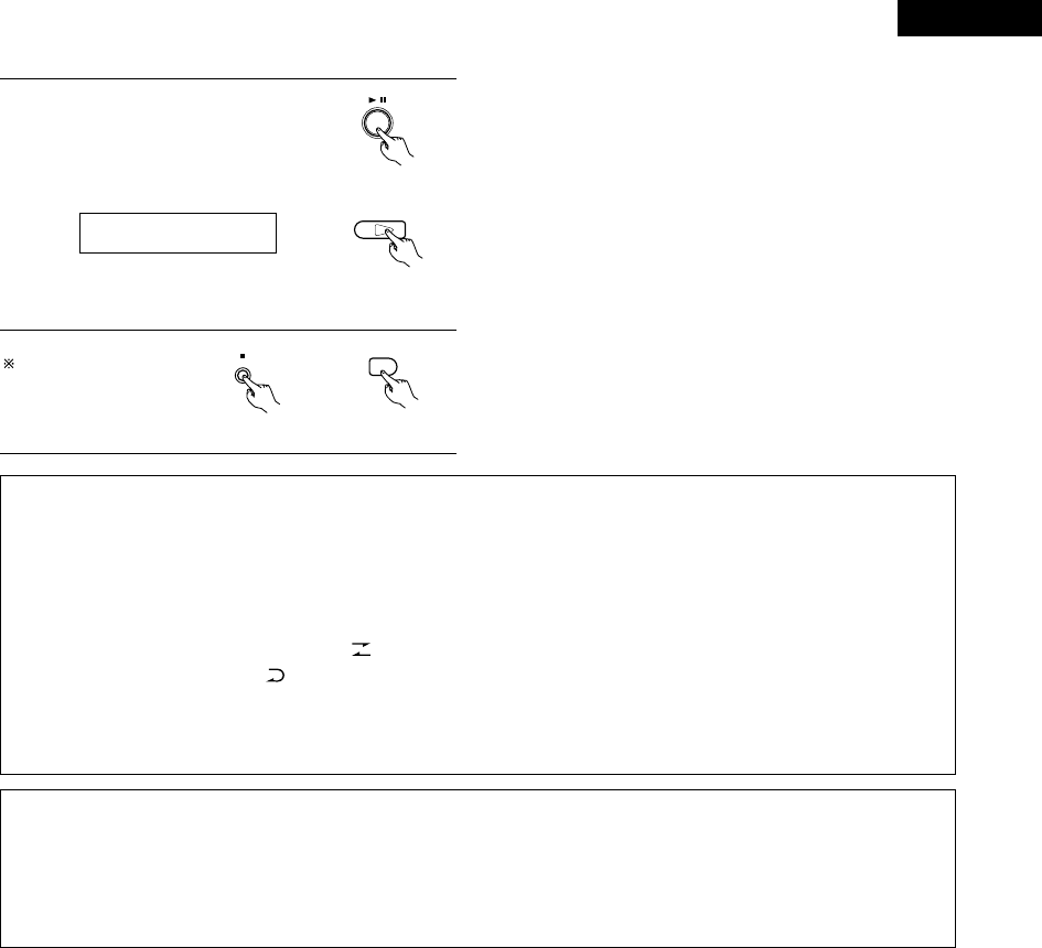
111
ENGLISH
6Press the play/pause button on the
ADV-M71 or the DVD play button on
the remote control unit.
•Playback of the CD and recording
onto the cassette tape start
simultaneously. ADV-M71
01Tr 00:01
To quit the edited
recording function, press
the ADV-M71’s stop
button.
BAND
2
ADV-M71 Remote control unit
NOTES:
•The edited recording function cannot be used with CDs containing 26 tracks or more.
•Load the cassette tape onto which you want to record into the cassette deck’s cassette tray with side A facing up before performing the
edited recording procedure. The tape is automatically wound to the beginning of the recordable section before recording starts.
•When using an already recorded cassette tape for edited recording, if the tape is longer than the set time, recording stops in the middle
of side B and the previous recording remains on the rest of the tape. Because of this, erase the cassette tape before using it.
•If the cassette deck’s reverse mode is set to when using the edited recording function, recording will stop after side A. Set the
cassette deck’s reverse mode to .
•Because the tracks are divided into sides A and B, it may not be possible to record all the tracks from the CD onto the cassette tape,
even if the tape is slightly longer than the CD’s total playing time.
•The 9, 8, 7and 6buttons do not work during edited recording.
2About synchronized recording onto the MD recorder (DMD-M31) and cassette deck (DRR-M31)
•Synchronized recording is possible with discs other than CDs (DVDs, video CDs, discs containing MP3 or WMA files, etc.).
•For digital and analog recoding during disc playback, see page 13.
•The synchronized recording function may not work properly for some discs. If so, record the disc manually by setting the recording mode
after start playback of the disc.
•The CD SRS function and the function for edited recording onto tapes only works with CDs.
DVD
1
Remote control unit

ENGLISH
112
21
LAST FUNCTION MEMORY
•This unit is equipped with a last function memory which stores the input and output setting conditions as they were immediately before the
power is switched off.
This function eliminates the need to perform complicated resettings when the power is switched on.
•The unit is also equipped with a back-up memory. This function provides memory storage when the power switch is off and with the power
cord disconnected.
22
INITIALIZATION OF THE MICROPROCESSOR
When the indication of the display is not normal or when the operation of the unit does not shows the reasonable result, the initialization of the
microprocessor is required by the following procedure.
1Press the power button to set the
standby mode, then unplug the set’s
power cord from the wall power outlet.
2Hold the following PLAY/PAUSE (1/3) button and STOP (2)
button after 30 second, and plug the AC cord into the outlet.
3Check that the entire display is flashing with an interval of
about 1 second, and release your fingers from the 2 buttons
and the microprocessor will be initialized. NOTES:
•If step 3 does not work, start over from step 1.
•If the microprocessor is reset, all the buttons and the setup
settings are reset to the factory default values.
B
BAND
PHONES
VOLUME
ON / STANDBY
DVD SURROUND RECEIVER ADV-M71
TONE/SDB
FUNCTION
MENU/SET +
-
SURROUND/SELECT
PUSH
-
PARAM.
1
22
ON / STANDBY
Red

113
ENGLISH
Check again before assuming the player is malfunctioning
2Are all the connections correct ?
2Are you following the instructions in the manual ?
2Are the speakers and other components operating properly ?
If this unit does not seem to be functioning properly, check the table below. If this does not solve the problem, this unit may be damaged. Turn
off the power, unplug the power cord from the power outlet, and contact your store of purchase or nearest Denon sales office.
23
TROUBLESHOOTING
Symptom Cause Measures Page
DISPLAY not lit and sound not produced
when power switch set to on.
•Power cord not plugged in securely. •Check the insertion of the power cord plug. 8
DISPLAY lit but sound not produced.
•Speaker cords not securely connected.
•Improper position of the audio function
button.
•Volume control set to minimum.
•MUTING is on.
•Digital signals not input Digital input
selected.
•Connect securely.
•Set to a suitable position.
•Turn volume up to suitable level.
•Switch off MUTING.
•Input digital signals or select input jacks to
which digital signals are being input.
8
44
42
46
47
Monitor doesn't display an image.
•Connections between the video output jack
of this unit and the input connector of the
monitor are incomplete.
•The input setting of the monitor TV is
different.
•Check whether the connections are correct.
•Set the input switching of the TV to the jack
to which the video input is connected.
11
—
The program cannot be copied from DVD
to the VCR.
•Almost all movie software contains a copy
prevention signal.
•A copy cannot be made. —
The subwoofer does not produce sound.
•Power is not being supplied to the
subwoofer.
•The subwoofer setting is made to "No" in
the setup.
•Switch on the power of the subwoofer.
•Change the setting to “Subwoofer” in the
setup.
—
29
This unit does not operate properly when
remote control unit is used.
•Batteries dead.
•Remote control unit too far from this unit.
•Obstacle between this unit and remote
control unit.
•Different button is being pressed.
•<and >ends of battery inserted in reverse.
•The mode selection of the remote control is
not properly selected. The DVD mode, AV
mode, or audio mode is not properly
selected.
•Replace with new batteries.
•Move closer.
•Remove obstacle.
•Press the proper button.
•Insert batteries properly.
•Press the remote control mode selection
button for the item you wish to operate. To
operate this unit, use with the DVD mode.
20
20
20
16
20
17
Remote control unit
Common problems when listening to the discs, tapes and FM broadcasts, etc.

ENGLISH
114
Symptom PageCheck
DVD operation
Playback does not start when PLAY
button is pressed.
Playback stops immediately.
—
6
7
•Is there condensation on the disc or player ? (Let stand for 1 or 2 hours.)
•Discs other than DVDs, video CDs and music CDs cannot be played.
•Disc is dirty. Wipe off the dirt.
Menu playback of video CD’s is not
possible.
—• Menu playback is not possible with anything but video CDs with playback control.
Picture is disturbed during the search
operation.
—• Some disturbance is normal.
Buttons do not operate. 42•Some operations are disabled for some discs.
No subtitles are displayed. —
95, 96
•Subtitles are not displayed for DVDs not containing subtitles.
•Subtitles are turned off. Turn the subtitles setting on.
Audio (or subtitle) language does not
switch.
95
95
•The audio (or subtitle) language does not switch for discs which do not include multiple audio
(or subtitle) languages.
•For some discs the audio (or subtitle) language cannot be switched when the operation to
switch it is performed, but can be switched on the menu screens.
Angle does not switch. 83•The angle cannot be switched for DVDs which do not contain multiple angles. In some cases
multiple angles are only recorded for specific scenes.
Playback does not start when the title is
selected.
103, 104•Check the “RATINGS SETUP” setting.
The password for rating level has been
forgotten.
Reset all the DVD setting to Factory
Preset.
103, 104•While the player is in the stop mode, hold the FUNCTION button and the MENU/SET button
down simultaneously for longer than 3 seconds (until “INITIALIZE” disappears from the TV
monitor).
The lock will be released and the DVD all default settings and picture settings will return to the
default values.
The disc is not played with the audio or
subtitle language set as the default
setting.
95•The disc does not play with the selected audio or subtitle language if that audio or subtitle
language is not included on that DVD.
Picture is not displayed in 4:3 (or 16:9). 99•Set the “TV ASPECT” default setting to the proper setting for the connected TV.
Menu screen messages for the desired
language do not display.
96, 97•Check the default setting for the disc language’s menu language.
Continuous noise is heard when receiving
FM programs
•Antenna cable is not properly connected. •Connect the antenna cable properly.
•Connect an outdoor antenna.
12
Hissing or continuous noise is heard when
receiving AM programs
•This may be noise from a TV or interference
from a radio station.
•Turn off the TV.
•Change the position and direction of the AM
loop antenna.
12
Humming noise is heard when receiving
AM programs
•The radio waves transmitted over the
power cord are being modulated.
•Unplug the power cord, flip the plug over in
the opposite direction, then plug the cord
back in.
12
Tuner

115
ENGLISH
24
SPECIFICATIONS
2Audio Section
•Power Amplifier Section
Rated output: Front: 35 W + 35 W (6 Ω/ohm load, 1 kHz, T.H.D. 10 %)
Output terminals: Speaker impedance: 6 to 16 Ω/ohms
•Analog Section
Input sensitivity/Input impedance: 200 mV/47 kΩ/kohms
Frequency response: 10 Hz to 50 kHz: +0, –3 dB (2 Channel setting, direct mode)
Signal-to-noise ratio: 98 dB (Direct mode)
Rated output: 0.6 V (Preamplifier output)
2Tuner Section
Reception frequency range: FM:
87.5 MHz to 108 MHz
AM: 522 kHz to 1611 kHz
Receiving sensitivity: FM: 1.5 µV/75 Ω/ohms AM: 20 µV
FM stereo separation: 35 dB (1 kHz)
•Digital Section
Digital input/output: Format — Digital audio interface
2Video Section
•AV1 connector
Video output 1 Vp-p, 75 Ω/ohms
S-video output Y (brightness) signal — 1 Vp-p, 75 Ω/ohms
C (color) signal — 0.3 Vp-p, 75 Ω/ohms
RGB output R/G/B signal — 0.7 Vp-p, 75 Ω/ohms
Audio output L/R (Fixed output)
2DVD Section
Signal Format: NTSC/PAL
Supported Discs: (1) DVD-VIDEO discs
12 cm single side 1 layer, 12 cm single side 2 layers,
12 cm both sides 2 layers (single side 1 layer),
8 cm single side 1 layer, 8 cm single side 2 layers,
8 cm both sides 2 layers (single side 1 layer)
(2) CompactDisc (CD-DA, VIDEO CD)
12 cm discs, 8 cm discs
Analog Audio Output: Output level: 1.1 Vrms (LINE-1, LINE-2 OUT)
2Clock/Timer Section
Clock method: Power line frequency synchronized method
Timer: Everyday/Once timer: One system each
Sleep timer: 120 minutes, maximum
2General
Power supply: 230 V AC, 50 Hz
Power consumption: 75 W
(At standby: Approximately 1 W)
Maximum external dimensions: 210 (W) x 95 (H) x 367 (D) mm (including feet, knobs, and connectors)
Weight: 3.5 kg
2Remote Control Unit RC-966
Remote control method: IR pulse method
Power supply: 3 V DC, using two AA batteries
✽Design and specifications are subject to change without notice in the course of product improvement.
This product incorporates copyright protection technology that is protected by method claims of certain U.S. patents and other intellectual
property rights owned by Macrovision Corporation and other rights owners. Use of this copyright protection technology must be authorized by
Macrovision Corporation, and is intended for home and other limited viewing uses only unless otherwise authorized by Macrovision
Corporation. Reverse engineering or disassembly is prohibited.
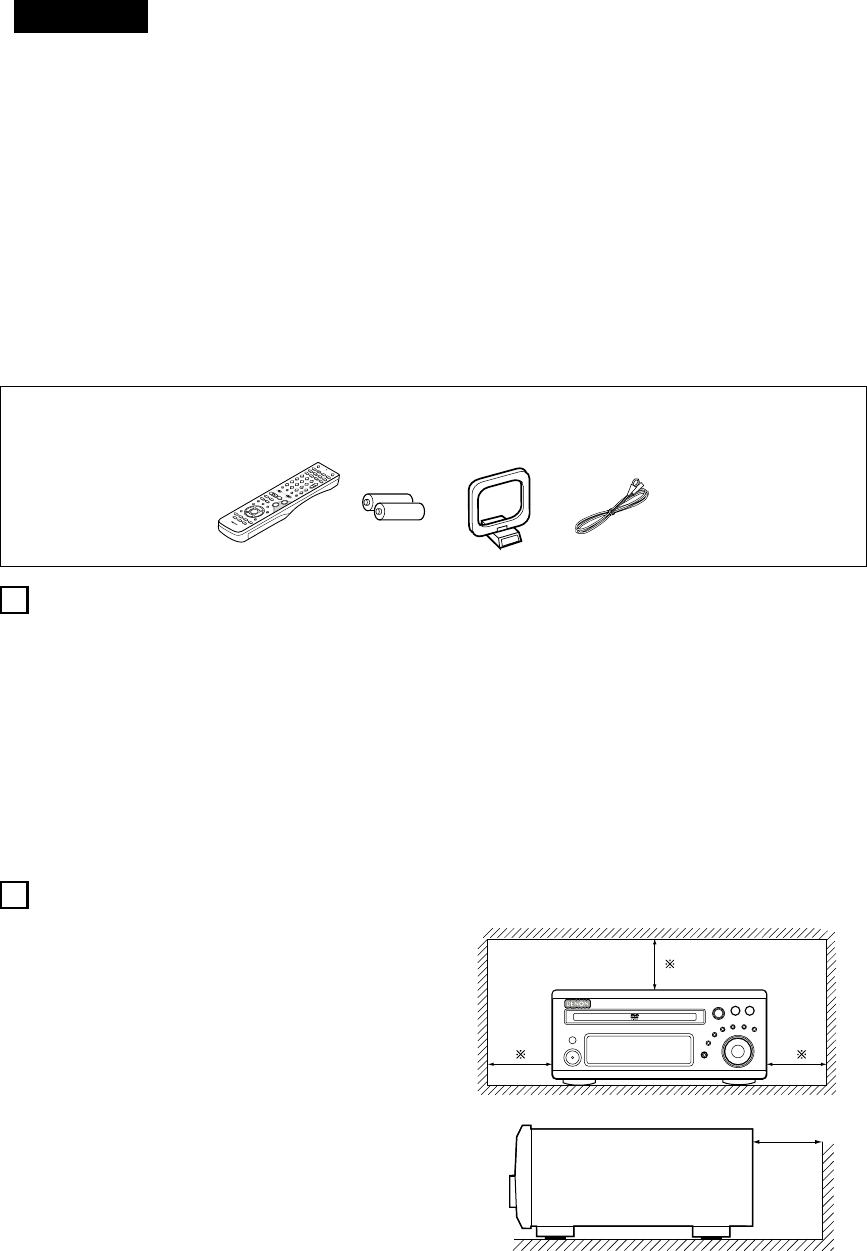
DEUTSCH
116
2ZUBEHÖRS
INHALT
zVOR INBETRIEBNAHME ........................................................................116
xVORSICHTSMASSNAHMEN ZUR INSTALLATION.................................116
cVORSICHTSMASSNAHMEN ZUR HANDHABUNG................................117
vHAUPTMERKMALE ................................................................................117
bDISCS......................................................................................................118
nVORSICHTSMASSNAHMEN ZUR HANDHABUNG VON DISCS............119
mANSCHLÜSSE.................................................................................120~126
,BAUTEILBEZEICHNUNGEN UND FUNKTIONEN...........................127~131
.FERNBEDIENUNGSGERÄT ............................................................132~140
⁄0 AUFSTELLUNG DES SYSTEMS .....................................................141~150
⁄1 WIEDERGABE ................................................................................151~156
⁄2 BETRIEB DER SURROUND-FUNKTIONEN ....................................156~158
⁄3 DOLBY / DTS SURROUND.............................................................159~161
⁄4 SURROUND WIEDERGABE ...........................................................162~174
⁄5 RADIO HÖREN ...............................................................................175~179
⁄6 BILDSCHIRMANZEIGE ...........................................................................180
⁄7 VERWENDUNG DER BILDSCHIRMANZEIGE................................181~198
⁄8 VERWENDUNG DES TIMERS........................................................199~205
⁄9 DIE VOREINSTELLUNGEN ÄNDERN (DVD) ..................................206~218
¤0 SYSTEMFUNKTIONEN ...................................................................219~223
¤1 SPEICHERUNG DER LETZTEN FUNKTION ............................................224
¤2 INITIALISIERUNG DES MIKROPROZESSORS .......................................224
¤3 FEHLERSUCHE...............................................................................225, 226
¤4 TECHNISCHE DATEN .............................................................................227
Stellen Sie sicher, daß die nachfolgend aufgeführten Zubehörteile dem Hauptgerät beiliegen:
qBetriebsanleitung................................................1 wMW-Rahmenantenne..........................................1 eFernbedienungsgerät (RC-966)...........................1
rR6P/AA-Batterien................................................2 tUKW-Raumantenne ............................................1 yUKW-Antennenadapter .......................................1
erty
2
ADV-M71
1
2
VOR INBETRIEBNAHME
VORSICHTSMASSNAHMEN ZUR INSTALLATION
Beachten Sie vor der Inbetriebnahme des Gerätes die
nachfolgend aufgeführten Hinweise:
•Transport des Gerätes
Um sowohl Kurzschlüsse als auch eine Beschädigung der Drähte in
den Anschlußkabeln zu vermeiden, müssen vor einem Transport
des Gerätes sowohl das Netzkabel als auch alle Anschlußkabel
zwischen den einzelnen Audio-Komponenten abgetrennt sein.
•Vor dem Einschalten des Netzschalters
Vergewissern Sie sich noch einmal, daß alle Anschlüsse richtig
ausgeführt worden sind und es keinerlei Probleme mit den
Anschlußkabeln gibt. Stellen Sie den Netzschalter vor dem
Anschließen bzw. Abtrennen von Anschlußkabeln stets auf die
Standby-Position.
•Bewahren Sie diese Betriebsanleitung an einem sicheren Ort
auf.
Bewahren Sie diese Betriebsanleitung nach dem Durchlesen
zusammen mit der Garantiekarte an einem sicheren Ort auf.
•Beachten Sie bitte, daß die Abbildungen in dieser
Betriebsanleitung für Erklärungszwecke vom aktuellen
Gerätemodell abweichen können.
Ton- und Bildstörungen können auftreten, wenn dieses Gerät oder ein
anderes Mikroprozessor anwendendes Elektrogerät in der Nähe eines
Tuners oder Fernsehgerätes betrieben wird.
Verfahren Sie in einem derartigen Fall wie nachfolgend aufgeführt:
• Installieren Sie das Gerät in größtmöglicher Entfernung zum Tuner
oder Fernsehgerät.
• Verlegen Sie die Antennendrähte vom Tuner oder Fernsehgerät in
ausreichender Entfernung sowohl zum Netzkabel als auch zu den
Eingangs-/Ausgangsanschlußkabeln dieses Gerätes.
• Ton- und Bildstörungen treten insbesondere bei Benutzung einer
Innenantenne oder beim Anschluß von 300 Ω/Ohm Zuleitungen
auf. Wir empfehlen die Verwendung von Außenantennen und
75 Ω/Ohm Koaxialkabeln.
Zur Gewährleistung einer ausreichenden Wärmeabfuhr, sollte
oberhalb, seitlich sowie hinter dem Gerät ein Mindestabstand
von 10 cm zur Wand oder zu anderen Komponenten eingehalten
werden.
DVD-SURROUND-RECEIVERGERÄT
B
10 cm oder mehr
10 cm oder mehr
Wand

DEUTSCH
117
3VORSICHTSMASSNAHMEN ZUR HANDHABUNG
•Umschalten der Eingangsfunktion, wenn keine
Eingangsbuchsen angeschlossen sind
Wenn die Eingangsfunktion umgeschaltet wird, wenn nichts an die
Eingangsbuchsen angeschlossen wurde, ist möglicherweise ein
Klicken zu hören. Drehen Sie in einem derartigen Fall entweder den
MASTER VOLUME-Regler herunter oder schließen Sie
Komponenten an die Eingangsbuchsen an.
•Stummschalten der PRE OUT-Buchsen und SPEAKER-
Anschluß-klemmen
Die PRE OUT-Buchsen und SPEAKER-Anschlußklemmen
beinhalten eine Stummschaltung. Aufgrund dieser Schaltung
werden die Ausgangssignale nach Einschalten des Netzschalters
oder Umschalten der Eingangsfunktion bzw. des Surround-Modus
oder bei Änderung einer anderen Einrichtungsfunktion einige
Sekunden lang stark reduziert.
Wenn die Lautstärke während dieser Zeit erhöht wird, ist der
Ausgang nach Ausschalten der Stummschaltung extrem hoch. Sie
sollten die Lautstärke daher erst dann einstellen, wenn die
Stummschaltung nicht mehr aktiv ist.
DVD-SURROUND-RECEIVERGERÄT
•Wann immer sich der Netzschalter in STANDBY-Position
befindet, bleibt das Gerät dennoch an die
Wechselstromleitung angeschlossen.
Trennen Sie unbedingt das Netzkabel ab, wenn Sie für einen
längeren Zeitraum, z.B. im Urlaub, nicht zuhause sind.
4HAUPTMERKMALE
Der ADV-M71 ist eine Kombination aus AV-Verstärker und DVD-
Player, in der die Hauptkomponenten eines Heimkinos in einem
einzigen kompakten, platzsparenden und stilvollen Gerät vereint
sind. Aufgrund der Aluminium-Blende sowie des
halbdurchlässigen Spiegeldisplays fügt sich dieses Gerät
harmonisch in die Ästhetik Ihres Raumes ein.
1. 2-Kanal Leistungsverstärker mit Dolby Virtual-Lautsprecher-
Kompatibilität
Der ADV-M71 ist mit zwei 35 W (6 Ω/Ohm 1 kHz, Klirrfaktor 10 %)
Leistungsverstärkern ausgestattet. Dadurch ist die Kompatibilität
mit der neuen Dolby Virtual Speaker-Technologie gegeben, mit der
Sie mit nur 2 Lautsprechern eine virtuelle 5.1-Kanalwiedergabe
erleben können. (Dolby Virtual Speaker ist ein Erzeugnis der Dolby
Laboratories.)
Ein hochwertiger Digitalsignalprozessor ermöglicht die Wiedergabe
von Dolby Digital- und Multikanal-Surround-Signalen im Dolby
Virtual Speaker-Modus. Dieser Modus ermöglicht in Kombination
mit einem Dolby Pro Logic II-Dekoder die Surround-Wiedergabe
sowohl von CDs als auch von anderen Stereoquellen.
2. 3,1-Kanal-Vorverstärker-Anschlüsse ermöglichen die
Erweiterung zu einem 5,1-Kanal-Surround-System
Bei der gleichzeitigen Verwendung eines handelsüblichen
Subwoofers mit eingebautem Verstärker und Leistungsverstärker
kann der ADV-M1 zu einem 5,1-Kanal-Surround-System erweitert
werden. Der ADV-M71 erstellt nicht nur ein genaues Klangfeld für
Multikanalquellen, sondern ist darüber hinaus mit der Weit-Modus-
Wiedergabe im Dolby Virtual Speaker-Modus kompatibel.
3. Dolby Pro Logic II-Decoder zur Erweiterung der Klangfeld-
Wiedergabe
Der ADV-M71 ist zur Erweiterung der Klangfeld-Wiedergabe für
Dolby Surround- und Stereo-Tonquellen mit einem Dolby Pro Logic
II-Decoder ausgestattet.
4. DENONs einzigartige Klangfeld-Simulation mit Hilfe von DSP
Bei der Verwendung von 2 Lautsprechern ist der ADV-M71 mit den
Rock Arena-, Jazz Club- und Video Game-Modi und bei der 5,1-
Kanal-Konfiguration zusätzlich mit den Stereo-, Mono Movie- und
Matrix-Modi kompatibel.
5. Hochwertiges DVD-Laufwerk für progressive Bildausgabe-
Kompatibilität
Der ADV-M71 ist mit verschiedenen von DVD-Quellen
angebotenen Funktionen kompatibel; einschließlich multipler
Audioauswahl (bis zu 8 Sprachen), multipler Untertitel-Funktion (bis
zu 32 Sprachen), multipler Winkel-Funktion, Wiedergabe-
Sperrfunktion usw.
6. Quick Setup und Bildschirmanzeige-Kompatibilität
Die DVD-Wiedergabe ist einfach durch Auswählen der
verwendeten Fernsehgerät- und Lautsprecher-Konfiguration
möglich. Selbst bei einer 5,1-Kanal-Lautsprecher-Konfiguration
können die Standard-Parameter automatisch durch Auswählen der
Raumgröße und Zuhörposition eingestellt werden. Die
Systemeinstellungen lassen sich bequem mit Hilfe der
Bildschirmanzeigen ausführen.
7. Fernbedienung mit Vorwahlspeicher-Funktion
Dem ADV-M71 liegt eine Fernbedienung mit integrierter
Vorwahlspeicher-Funktion bei. Die Fernbedienungs-Befehlcodes
für MD-Recorder der D-M31-Serie, für Kassettendecks und andere
zur Fernbedienung ausgelegten DENON-Komponenten sowie für
Fernsehgeräte und Videodecks von anderen großen Herstellern
sind im Speicher vorprogrammiert.
8. Praktische Systemfunktionen
Wenn dieses System an einen MD-Recorder der D-M31-Serie und
ein Kassettendeck angeschlossen wird, können Systemfunktionen
wie die automatische Funktionswahl, die synchronisierte
Aufnahme und Timer-Aufnahme/-Wiedergabe schnell und einfach
ausgeführt werden.

DEUTSCH
120
RLRLRLRL
(L) (R)
7ANSCHLÜSSE
•Schließen Sie das Netzkabel erst dann an, wenn alle Anschlüsse
vorgenommen wurden.
•Vergewissern Sie sich, dass der linke und rechte Kanal richtig
angeschlossen ist (links mit links, rechts mit rechts).
•Stecken Sie die Stecker fest ein. Unvollständige Anschlüsse
erzeugen Rauschen.
•Beachten Sie, dass das Zusammenbinden von Stiftsteckerkabeln
mit Netzkabeln neben einem Leistungstransformator Brummen
oder Rauschen erzeugt.
•Brummen und Rauschen kann erzeugt werden, wenn ein
angeschlossenes Audiogerät einzeln verwendet wird, ohne dass
die Stromversorgung dieser Einheit eingeschaltet ist. Schalten Sie
in solch einem Fall dieses Gerät ein.
(1) Anschluss der Audiokomponenten (D-M31 Series)
•Der ADV-M71 kann an einen MD-Recorder der D-M31-Serie (DMD-M31) und ein Kassettendeck (DRR-M31) angeschlossen werden.
•Bedienungshinweise zum als Zubehör erhältlichen MD-Recorder (DMD-M31) und zum Kassettendeck (DRR-M31) finden Sie in der
entsprechenden Bedienungsanleitung.
•Nur der MD-Recorder DMD-M31 und das Kassettendeck DRR-M31 können mit Hilfe der Systemanschlüsse direkt an den ADV-M71
angeschlossen werden.
HINWEIS:
•Dieses Gerät enthält digitale Schaltkreise, deren Signale die
Farbwiedergabe von Fernsehgeräten beeinträchtigen können. Wenn
dieser Effekt auftritt, muß für eine möglichst große Distanz zwischen
Gerät und Fernseher gesorgt werden.
Lautsprecheranschluß
Schließen Sie das Lautsprechersystem für den linken Kanal (von vorne
betrachtet) an den mit “L” bezeichneten Klemmen und das
Lautsprechersystem für den rechten Kanal an den mit “R” bezeichneten
Klemmen an. Beachten Sie etwaige nähere Hinweise in der
Bedienungsanleitung zu Ihrem Lautsprechersystem. Achten Sie darauf, daß die
Impedanz der Lautsprecher mindestens 6Ω/Ohm beträgt.
Als Zubehör erhältlicher Subwoofer
mit integriertem Verstärker
ADV-M71 DVD-
Surround-
Receiver
Lautsprechersysteme
SC-M51
Oder als Zubehör erhältlicher
Lautsprecher
UKW-Zimmerantenne
(im Lieferumfang
enthalten ) MW-
Rahmenantenne
(im Lieferumfang
enthalten)
NETZKABEL
230 V Wechselstrom, 50 Hz
Der ADV-M71 hat eine integrierte Uhr-Funktion.
Daher sollte der Netzstecker an eine Steckdose
angeschlossen werden, die kontinuierlich
Spannung führt.
Audiokabel
Optische
Übertragungskabel
Systemkabel
Lautsprecherkabel
Stereo-Audiokabel

DEUTSCH
121
RLRL
1
18Tr02m 46s
-60 -40 -30 -20 -12 -6 -2 0
L
dB
R
1
18Tr02m 46s
-60 -40 -30 -20 -12 -6 -2 0
L
dB
R
DVD SURROUND RECEIVER ADV-M71
B
BAND
PHONES
VOLUME
ON / STANDBY
TONE/SDB
FUNCTION
MENU/SET
+
-
SURROUND/SELECT
PUSH
-
PARAM.
DVD SURROUND RECEIVER ADV-M71
B
BAND
PHONES
VOLUME
ON / STANDBY
TONE/SDB
FUNCTION
MENU/SET
+
-
SURROUND/SELECT
PUSH
-
PARAM.
ACHTUNG:
•Mit Hilfe der Systemanschlüsse kann nur ein MD-Recorder und ein Kassettendeck an den ADV-M71 angeschlossen werden. Die
Systemfunktionen können nicht einwandfrei ausgeführt werden, wenn zwei MD-Recorder oder zwei Kassettendecks mit Hilfe der
Systemanschlüsse angeschlossen worden sind.
•Wenn sich der Netzschalter des Geräts in Bereitschaftsstellung (STANDBY) befindet, ist das Gerät mit Netzspannung verbunden.
•Ziehen Sie daher unbedingt den Netzstecker aus der Steckdose, wenn Sie beispielsweise verreisen.
Systemfunktionen
Systemoperationen, wie Timer- und autom. Einschaltfunktion, und
Fernbedienungsoperationen können nur dann ausgeführt werden, wenn alle
Cinch-Stiftsteckerkabel und Systemanschlusskabel zwischen den Geräten
angeschlossen sind; vergewissern Sie sich, dass alle Anschlüsse
ordnungsgemäß wie im Diagramm gezeigt ausgeführt werden. Das Abziehen
von Steckern bei laufender Anlage kann Funktionsstörungen hervorrufen.
Ziehen Sie immer erst den Netzstecker ab, bevor Änderungen an den
Anschlüssen vorgenommen werden.
HINWEISE:
•Schließen Sie den Netzstecker erst an, nachdem alle übrigen Anschlüsse
komplett hergestellt wurden. Achten Sie darauf, daß der Anschluß der
Lautsprecherkanäle (L zu L (weiß) und R zu R (rot)) gemäß obigem Schema
vorgenommen wird.
•Schließen Sie ausschließlich Audiogeräte an den AC OUTLET-Anschluss
an. Hier dürfen keine Haartrockner usw. angeschlossen werden.
•Achten Sie auf festen Sitz der Steckverbinder. Lose Stecker können
Störgeräusche verursachen.
•Achten Sie darauf, daß die Lautsprecher-Anschlußkabel am Lautsprecher
und am Gerät mit gleicher Polarität angeschlossen werden (+ an +, – an
–). Bei falscher Polung ist der Ton im Mittelbereich schwach, die
Positionen der einzelnen Instrumente sind nicht eindeutig auszumachen
und der Stereoeffekt geht verloren.
•Warten Sie nach dem Abziehen des Netzsteckers etwa 5 Sekunden, bevor
dieser wieder eingesteckt wird.
•Verbindungskabel (Kabel mit RCA-Stecker) sollten nicht unmittelbar neben
spannungsführenden Kabeln verlegt werden, da dies zu Brumm- oder
sonstigen Störgeräuschen führen kann.
MD-Recorder
(DMD-M31)
(als Zubehör erhältlich)
Kassettendeck
(DRR-M31)
(als Zubehör erhältlich)
ADV-M71
DRR-M31
DMD-M31
(Horizontale Installation)
Nehmen Sie die Montage
gemäß einer dieser Skizzen vor.
Achten Sie in jedem Fall darauf,
daß die Belüftungsöffnungen
des CD/Tuner-Geräts nicht
verschlossen werden.
ADV-M71
DRR-M31
DMD-M31
(Vertikale Installation)
Stereo-Audiokabel
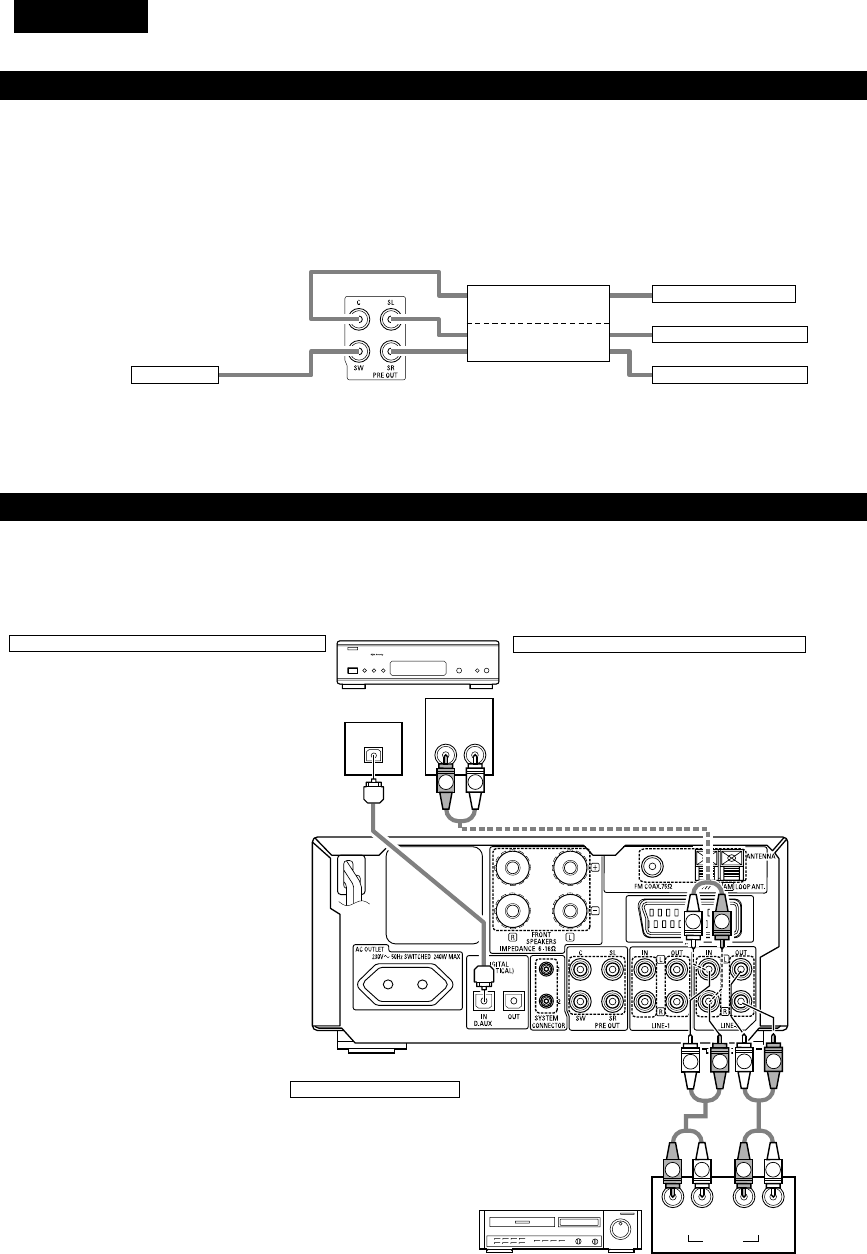
DEUTSCH
122
LR
AUDIO
OUTL
R
LROUT IN L
R
AUDIO
OUT
OPTICAL
B
R
L
L
R
LR
L
RL
R
R
L
(3) Anschluss der Audiosignale eines digitalen Satelliten-Tuners und VCRs
•Schließen Sie die Videosignale direkt an das Fernsehgerät an und schalten Sie das Fernsehbild um.
•Lesen Sie bei der Durchführung der Anschlüsse auch die Bedienungsanleitungen der anderen Komponenten.
Anschluss an den optischen Digitaleingangsanschluss
•In den optischen Digitaleingangsanschluss werden
nur Audiosignale eingegeben.
•Verwenden Sie für den Anschluss an den optischen
Übertragungsanschluss (OPTICAL) ein
handelsübliches optisches Übertragungskabel.
Anschluss eines digitalen Satelliten-/Kabeltuners
•Schließen Sie bei Tunern mit integrierten optischen
Digitalausgangs-Anschlüssen den Digitalausgangs-Anschluss
mit Hilfe eines optischen Übertragungskabels an den DIGITAL
D.AUX IN-Anschluss des ADV-M71 an.
•Schließen Sie die Audioausgangs-Anschlüsse beliebig
entweder an den unbelegten LINE-1- oder LINE-2-Anschluss
des ADV-M71 an.
Anschluss eines Videodecks
•Schließen Sie die Audioausgangs- und Audioeingangs-
Anschlüsse mit Hilfe eines Stiftsteckerkabels beliebig
entweder an den LINE-1- oder LINE-2-Anschluss des ADV-
M71 an.
Videodeck
Digitaler Satelliten-/Kabeltuner
(2) Anschluss der PRE OUT-Anschlüsse (nur bei Multikanal-Einstellungen)
•Bei der gleichzeitigen Verwendung eines handelsüblichen Subwoofers mit integriertem Verstärker und Leistungsverstärker kann der ADV-M71
zu einem 5,1-Kanal-Surround-System erweitert werden.
•Lesen Sie bei der Durchführung der Anschlüsse auch die Bedienungsanleitungen der anderen Komponenten.
•Stellen Sie die Lautsprecher zur Durchführung der 5,1-Kanal-Einstellung im Quick System-Setup auf “5.1 CH SURROUND” und wählen Sie
“Room Setting” und “Listening Position”. (Siehe die Seiten 143 bis 144.)
SUBWOOFER
•Schließen Sie den Subwoofer mit
integriertem Verstärker an.
POWER AMPLIFIER
(für Center-Kanal)
POWER AMPLIFIER
(für Surround-Kanal)
•Schließen Sie den
Leistungsverstärker für das
Center- und Surround-
Lautsprechersystem an.
Center-Lautsprecher
Surround-Lautsprecher (L)
Surround-Lautsprecher (R)
IN
IN
IN
IN

DEUTSCH
123
(4) Anschluss eines Fernsehgerätes
•Verwenden Sie ein im Handel erhältliches 21-pol. SCART-Kabel, um den 21-pol. SCART-Anschluss des TV an den 21-pol. SCART-Anschluss des
ADV-M71’s (AV1) anzuschließen.
Monitor TV
•Schließen Sie die Videoausgänge dieses Gerätes direkt und
nicht über einen VCR (Videokassettenrecorder) an das
Fernsehgerät an.
•Stellen Sie den “TV TYPE” unter “VIDEO SETUP” im “DVD
SETUP” ein, damit es zu einer Übereinstimmung mit dem TV-
Videoformat kommt. Wenn der TV PAL-formatiert ist, stellen Sie
PAL ein. (Siehe Seite 141.)
•Die Werkseinstellung lautet auf “PAL”. Wenn diese Funktion bei
aktiviertem Stoppmodus auf “DVD” eingestellt ist, kann die
Einstellung auch mit der “NTSC/PAL”-Taste auf der
Fernbedienung geändert werden. Falls die Einstellung vom
Videoformat Ihres Fernsehgerätes abweicht, können Sie das
Videoformat von der Fernbedienung aus umschalten. Stellen Sie
den “TV TYPE“ unter “VIDEO SETUP” im “DVD SETUP” auf
die dem Videoformat Ihres Fernsehgerätes entsprechende
Position.
HINWEISE:
•Die Audio- und Videosignale für die am Gerät gewählte Funktion werden ausgegeben.
Audioausgangssignale
•Die Tuner- und DVD-Audiowiedergabe-Signale sowie die Audiosignale, die an den AUDIO INPUT-Buchsen eingegeben werden, werden
ausgegeben.
•Wenn eine Dolby Digital-DVD abgespielt wird, werden die Audiosignale vor der Ausgabe in 2-Kanal-Signale konvertiert. (Audiosignale werden
während der DTS-Wiedergabe nicht ausgegeben.)
•Der Audioausgangspegel ist festgelegt. Wenn Sie den Sound nicht mit dem angeschlossenen TV wiedergeben wollen, stellen Sie die TV-
Lautstärke auf ein Minimum ein.
Videoausgangssignale
•Die DVD-Videowiedergabe-Signale und die Videosignale, die an den VIDEO- oder S-VIDEO INPUT-Buchsen eingegeben werden, werden
ausgegeben.
•Die Wahl der VIDEO-, S-VIDEO- und DVD RGB-Videosignale wird unter dem Systemsetup-Punkt “AV1 VIDEO OUTPUT” vorgenommen.
(Werkseitig sind sie alle auf “VIDEO” eingestellt. Siehe Seite 141.)

DEUTSCH
124
1
4
23
(5) Anschluss von Antennen
RICHTUNG DES
SENDERS
75 Ω/Ohm
KOAXIALKABEL
UKW-ANTENNE
UKW-INNENANTENNE
(mitgeliefert)
MW-
RAHMENANTENNE
(mitgeliefert)
MW-
AUSSENANTENNE
ERDE
MW-Rahmenantennenbaugruppe
Schließen Sie an den
MW-
Antennenanschlüssen an.
Entfernen Sie den
Plastikbinder und ziehen Sie
die Verbindungsleitung
auseinander.
Biegen Sie in
Gegenrichtung.
a. Mit der
Antennenach
oben auf eine
ebene Fläche
b. Montage der
Antenne an der
Wand.
Stellen
Mittels den Installationsbohrungen
an der Wand, etc. befestigen
Anschluß der MW-Antennen
1. Drücken Sie den
Hebel.
2. Führen Sie die
Antennen-leitung ein.
3. Lassen Sie den
Hebel wieder los.
HINWEISE:
•Schließen keine zwei UKW-Antennen gleichzeitig an.
•Selbst wenn eine externe MW-Antenne angeschlossen ist, entfernen Sie
nicht die MW-Rahmenantenne.
•Stellen Sie sicher, daß keine blanke Antennenanschlußdrähte die
Metallteile des Anschlußfeldes berühren.
ADAPTER FÜR UKW-
INNENANTENNE
(Zusatzausstattung)
•Ein UKW-Antennenkabelstecker des Typs F kann direkt angeschlossen werden.
•Wenn kein UKW-Antennenkabelstecker des Typs F zur Verfügung steht, nehmen Sie den Anschluss mit dem beiliegenden Antennenadapter
vor (Zusatzausstattung).

DEUTSCH
125
(6) Tonausgang von den digitalen Audioausgangsanschlüssen dieses Gerätes
2Bei Wiedergabe einer Disc mit dem ADV-M71 (Digital Out)
Siehe Seite
DVD-Video
DVD-Audio
(nur Video-Teil)
Audioaufnahmeformat
Dolby Digita
CP : EIN
Video CD
CP : AUS
DTS
MPEG audio
48 kHz
•Linear-PCM-Audio ist das Signalaufnahmeformat, das bei Musik-CDs verwendet wird.
Während die Signale bei 44,1 kHz/16 Bit für Musik-CDs aufgenommen werden, werden DVDs bei 48 kHz/16 Bit bis 96 kHz/24 Bit
aufgenommen, wodurch eine höhere Soundqualität als bei Musik-CDs erzielt wird.
Music CD
MP3/WMA CD
Linear PCM
96 kHz
32 ~ 48 kHz/16 Bit PCM
44,1 kHz/16 Bit PCM
44,1 kHz/16 Bit PCM
LPCM-Konversionsmodus : AUS
LPCM-Konversionsmodus : AUS
MPEG 1
Linear PCM
MP3/WMA
LPCM-Konversionsmodus : EIN
LPCM-Konversionsmodus : EIN
LPCM-Konversionsmodus : AUS
Digital-Ausgang : PCM-Konversion
Digital-Ausgang : Normal
Digital-Ausgang : PCM-Konversion
Digital-Ausgang : Normal
Digital-Ausgang : PCM-Konversion
Digital-Ausgang
: Normal
Einstellungen:
96 kHz PCM (ohne Kopierschutz)
48 kHz/16 Bit PCM (bei Kopierschutz)
48 kHz/16 Bit PCM
48 kHz/16 Bit PCM
48 kHz/16 ~24 Bit PCM
2 Kanäle PCM-Daten (48 kHz/16 Bit)
DTS-Bitfluss
2 Kanäle PCM-Daten (48 kHz/16 Bit)
2 Kanäle PCM-Daten (48 kHz/16 Bit)
2 Kanäle PCM-Daten (48 kHz/16 Bit)
Dolby Digital-Bitfluss
Digitaler Audiodatenausgang
213
213
213
2Über die analogen Aufnahmeausgänge LINE-1 und LINE-2
Wenn der DVD- oder D.AUX-Digitaleingang ausgewählt wurde:
•Dolby Digital-, DTS- und PCM-Digitalsignale werden vor der Ausgabe automatisch in 2-Kanal-Stereosignale konvertiert (außer im Dolby
Headphone-Modus) und können analog aufgenommen werden. (Einzelheiten über den Dolby Headphone-Modus finden Sie nachfolgend.)
Wenn TUNER, LINE-1 oder LINE-2 ausgewählt wurde:
•Die vom Tuner oder einem anderen an die LINE-1 oder LINE-2 analogen Eingangsanschluss (IN) angeschlossenem Gerät ausgewählten
Analogaudio-Signale werden unabhängig vom Eingangs- oder Surround-Modus des ADV-M71 unverändert ausgegeben. (Dasselbe gilt für das
an die D.AUX-Anschlüsse angeschlossene Gerät, wenn “LINE-2” unter “⁄0 AUFSTELLUNG DES SYSTEMS – (3) Detailliertes System-Setup –
[6] Funktionseinstellungen” auf “D.AUX” eingestellt ist.)
Aufnahmeausgang während der Wiedergabe einer DVD- oder D.AUX-Digitaleingangsquelle im Dolby Headphone-Modus:
•Wenn im Dolby Headphone-Modus ein DVD- oder Digitaleingang ausgewählt wurde, werden die zu dem Zeitpunkt wiedergegebenen analogen
Audiosignale ausgegeben und können analog aufgenommen werden. (Siehe die Seiten 170 und 171.)
Vorsichtsmaßnahmen während der analogen Aufnahme von DVDs oder Digitaleingangsquellen:
•Ändern Sie während der Aufnahme weder den Eingangsmodus, Surround-Modus noch die Surround-Parameter des ADV-M71. Dies würde
kurze Aufnahmeton-Ausfälle verursachen.
Wir empfehlen die Surround-Einstellung “STEREO” oder “DIRECT”.
•Bei der Verwendung der Kopfhörer wird die Aufnahme automatisch im Dolby Headphone-Modus ausgeführt. Trennen Sie während der
Aufnahme nicht die Kopfhörer ab, und ändern Sie auch nicht den Kopfhörer-Modus.

DEUTSCH
126
•Dieses Gerät ist mit einer Hochgeschwindigkeits-Schutzschaltung ausgestattet. Zweck dieser Schutzschaltung ist es, die Lautsprecher unter
bestimmten Umständen zu schützen; z.B. wenn der Ausgang des Leistungsverstärkers versehentlich kurzgeschlossen wurde und aufgrund
dessen Starkstrom fließt, wenn die Umgebungstemperatur des Gerätes unnatürlich hoch ist oder wenn das Gerät über einen längeren
Zeitraum hinweg mit hoher Lautstärke betrieben wird, was einen extremen Temperaturanstieg zur Folge hat.
Wenn die Schutzschaltung aktiviert ist, wird der Lautsprecher-Ausgang ausgeschaltet und das Netz-LED blinkt. Verfahren Sie in einem
derartigen Fall wie folgt: Schalten Sie das Gerät aus, überprüfen Sie, ob irgendwelche Fehler mit der Verdrahtung der Lautsprecherkabel oder
Eingangskabel vorliegen und lassen Sie das Gerät im Falle einer starken Erhitzung abkühlen. Verbessern Sie die Belüftungsbedingungen und
schalten Sie das Gerät wieder ein.
Wird die Schutzschaltung erneut aktiviert, obwohl weder die Verdrahtung noch Belüftung Grund zur Beanstandung gibt, schalten Sie das
Gerät aus und kontaktieren Sie einen DENON-Kundendienst.
Schutzschaltung
•Die Schutzschaltung wird möglicherweise aktiviert, wenn das Gerät über einen langen Zeitraum hinweg mit hoher Lautstärke betrieben wird
und Lautsprecher mit einer niedrigeren als der angegebenen Impedanz angeschlossen sind (z.B. Lautsprecher mit einer niedrigeren
Impedanz als 4 Ω/Ohm). Bei aktivierter Schutzschaltung ist der Lautsprecher-Ausgang ausgeschaltet. Schalten Sie das Gerät aus, lassen Sie
die Anlage abkühlen, verbessern Sie die Belüftungsbedingungen und schalten Sie das Gerät wieder ein.
Hinweis zur Lautsprecher-Impedanz
•Bei den Lautsprecherausgängen dieses Gerätes werden Signale mit der entgegengesetzten Phase der “+”-Seiten-Ausgangsanschluss-
Signale auch vom “-“-Seiten-Ausgangsanschluss ausgegeben.
Führen Sie keinen Anschluss an ein Gerät zum Umschalten zwischen mehreren Lautsprechern (einem Lautsprecherwähler oder
Audiokanalwähler) aus und wenden Sie ausschließlich das in diesem Handbuch beschriebene Anschlussverfahren an. Andernfalls könnten
Beschädigungen die Folge sein.
Vorsichtsmaßnahmen zum Anschluss
(7) Lautsprechersystem-Anschlüsse
Schalten Sie vor dem Anschuss der Lautsprechersysteme
unbedingt deren Stromversorgung aus.
•
Schließen Sie die sich auf der Rückseite der Lautsprechersysteme
befindlichen Eingangsanschlüsse (siehe Abbildung) mit den im
Lieferumfang enthaltenen Kabeln an die Lautsprecher-
Ausgangsanschlüsse des Verstärkers an. Schließen Sie das
Lautsprechersystem für den linken Verstärkerkanal an die “L”-
Anschlüsse und das für den rechten Verstärkerkanal an die “R”-
Anschlüsse an. Achten Sie dabei auf die richtige Ausrichtung der
Polarität (“≈” und “√”). Zeichen). Eine vertauschte Polarität hat
einen unnatürlichen Klang mit ausgeschalteter Phase oder keinem
niedrigen Tiefenklang zur Folge. Stellen Sie darüber hinaus sicher,
dass beide Anschlussknöpfe richtig fest sind.
Anschlüsse
(Bei den roten Anschlüssen auf der rechten Seite handelt es sich
um die “≈”, Anschlüsse, bei den Anschlüssen auf der linken Seite
um die“√”Anschlüsse.)
Lösen Sie die Anschlussknöpfe, setzen Sie die
Kerndrähte der Kabel ein und ziehen Sie die
Knöpfe fest.
Schließen Sie an die “≈” Seite des Verstärkers
an (kupferfarben).
Schließen Sie an die “√”
Seite des Verstärkers an
(silberfarben).
HINWEIS:
Stellen Sie sicher, dass sich die Kerndrähte
nicht gegenseitig berühren.
Anschluss der Lautsprecherkabel
Schließen Sie die sich auf der Rückseite der Lautsprechersysteme
befindlichen Eingangsanschlüsse (siehe Abbildung rechts) mit den im
Lieferumfang enthaltenen Kabeln an die Lautsprecher-
Ausgangsanschlüsse des ADV-M71 an.
•Schließen Sie das Lautsprechersystem für den linken Kanal an die
“L”-Anschlüsse und das Lautsprechersystem für den rechten Kanal
an die “R”-Anschlüsse an. Achten Sie dabei auf die richtige
Ausrichtung der Polarität (“+” und “-“).
•Beachten Sie, dass bei vertauschter Polarität die Phase
möglicherweise ausgeschaltet ist und der Tiefenklang fehlt, was
einen unnatürlichen Klang zur Folge hätte. Stellen Sie darüber
hinaus sicher, dass beide Schrauben der Lautsprecheranschlüsse
festgezogen sind.
Drehen Sie die Kerndrähte
entweder fest zusammen
oder spannen Sie sie ab.
qDrehen Sie den
Lautsprecheranschluss
zum Lösen entgegen
dem Uhrzeigersinn.
wSetzen Sie die
Kerndrähte des
Kabels ein.
eDrehen Sie den
Lautsprecheranschluss
zum Festziehen im
Uhrzeigersinn.
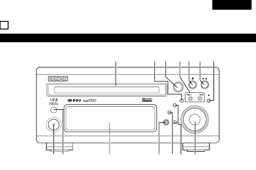
DEUTSCH
127
8BAUTEILBEZEICHNUNGEN UND FUNKTIONEN
Frontteil
•Einzelheiten hinsichtlich Funktionen dieser Bestandteile können den in Klammern ( ) stehenden Seiten entnommen werden.
B
BAND
PHONES
VOLUME
ON / STANDBY
DVD SURROUND RECEIVER ADV-M71
TONE/SDB
FUNCTION
MENU/SET +
-
SURROUND/ SELECT
PUSH
-
PARAM.
qwertu
oi
!0
!1
!4 !3
y
!2
qON/STANDBY taste................................................................(142)
wFernbedienungssignalsensor..................................................(132)
eDisplay
rKopfhörerbuchse (PHONES) ..................................................(170)
tFUNCTION taste ....................................................................(156)
yTONE/SDB taste.....................................................................(158)
uLautstärke-Regler (VOLUME).................................................(154)
i2BAND taste ...............................................................(154, 175)
o13 taste.......................................................................(153, 155)
!0 5taste ..................................................................................(153)
!1 8/ – und + / 9taste ...........................................(155, 175)
!2 SURROUND/SELECT taste ....................................................(162)
PARAMETER taste .................................................................(163)
!3 MENU/SET taste ....................................................................(177)
!4 Disc-Fach................................................................................(152)

DEUTSCH
128
qLED Anzeige
wSLEEP taste............................................................................(205)
eNTSC/PAL taste......................................................................(123)
rCLEAR taste...........................................................................(185)
tA-B REPEAT taste ..................................................................(184)
yPROGRAM/DIRECT taste.......................................................(185)
uREPEAT taste .........................................................................(183)
iEingangsquellen-/Surroundmodus-Auswahltaste
* SYSTEM taste.............................(130, 131, 133, 134, 135, 140)
oCALL taste..............................................................................(185)
!0 TEST TONE taste ...................................................................(148)
!1 INPUT MODE taste................................................................(156)
!2 DVD PLAY taste .....................................................................(153)
!3 DVD STOP taste.....................................................................(154)
!4 DVD SKIP taste ......................................................................(155)
!5 DVD SEARCH taste........................................................(155, 156)
!6 DVD PAUSE taste...................................................................(155)
!7 STATUS taste .........................................................................(157)
!8 SETUP taste ...........................................................................(142)
!9 CH.SELACT taste ...................................................................(148)
@0 RETURN taste ........................................................................(154)
@1 DISPLAY taste ........................................................................(181)
@2 ANGLE taste...........................................................................(195)
@3 AUDIO taste...........................................................................(193)
@4 Fernbedienungssignalsender .................................................(132)
@5 POWER taste .........................................................................(142)
@6 SYSTEM taste........................................................(130, 133, 134)
@7 ZOOM taste ...........................................................................(198)
@8 SLIDE taste ............................................................................(192)
@9 SEARCH MODE taste ............................................................(155)
#0 RANDOM taste ......................................................................(186)
#1 TUNING/TV VOL taste............................................................(175)
#2 TUNING/TV taste....................................................................(176)
#3 FUNCTION taste ....................................................................(156)
#4 SURROUND taste ..................................................................(157)
#5 Modusw
ähler
..................................................................(129, 130)
#6
Lautstärke-Hauptbedienungstasten
............................................(154)
#7 MUTING taste ........................................................................(158)
#8 TONE/SDB taste.....................................................................(158)
#9 ENTER taste...........................................................................(141)
$0 CURSOR ................................................................................(141)
$1 SURROUND PARAMETER taste............................................(162)
$2 TOP MEMU taste...................................................................(196)
$3 MENU taste............................................................................(197)
$4 SUBTITLE taste......................................................................(194)
$5 * SYSTEM taste.............................................(130, 133, 134, 140)
Fernbedienung
•Einzelheiten hinsichtlich Funktionen dieser Bestandteile können den in Klammern ( ) stehenden Seiten entnommen werden.
•Einige der sich auf der Fernbedienung befindlichen Tasten besitzen zwei Funktionen.
Die Funktionen werden mithilfe der Betriebswahltasten der Fernbedienung gewechselt.
+
-
+
-
RC-966
A / V
3
A-B REPEAT
SEARCH MODE
ONOFF
REPEAT RANDOM
CLEAR ZOOMSLIDE MODE
PROG/ DIRECT
MEMO BAND
RTCTPTYRDS
MODE
STAT U S
RETURN
ANGLE AUDIO
SUB TITLE
SETUP TONE /SDB
FUNCTIONSURROUNDINPUT MODETEST TONE
DVD
TUNER
CH
3
-
+
21
654
987
0/10
CALL
ENTER
MUTING
+10
DISPLAY MENU
TOP MENU
SYSTEM MD
CDR TAPE
TUNER TV / VCR
SURROUND
PARAMETER
CH SELECT
VCR
NTSC/PAL
SLEEP
ENTER
CD SRS
EDIT/MENUCHARAC.
REC
TIMETITLE
TUNING /
TV VOL
TV CH TV CH
TUNERDVD
MD/ LINE-1 TAPE/ LINE-2
AUTO DECODE
VIRTUALDIRECT
5CH STEREO
STEREO
D.AUX
-
+
VCR CH
IN/SURR.
IN/SURR.
DVD
T VT V INSOURCE
9
8
21
76
+
-
q
w
e
r
t
y
u
i
o
!0
!1
!2
!3
!4
!5
!6
!7
!8
!9
@0
@1
@2
@3
@4
@5
@6
@7
@8
@9
#0
#1
#2
#3
#4
#5
#7
#8
#9
$0
$1
$2
$3
$4
$5
#6
•Lesen Sie hinsichtlich der Einzelheiten über die Funktion und Bedienung der verschiedenen Bauteile die (in Klammern) angegebenen Seiten.
•Bei den angegebenen Tasten Tasten handelt es sich um DVD-Bedienungstasten, die in Funktion sind, wenn der Fernbedienungsmodus-
Wahlschalter auf die und Position gestellt ist.
•Die Funktionen der Systemtasten (*) werden mit Hilfe des Fernbedienungsmodus-Wahlschalters umgeschaltet.
DVD
A / V
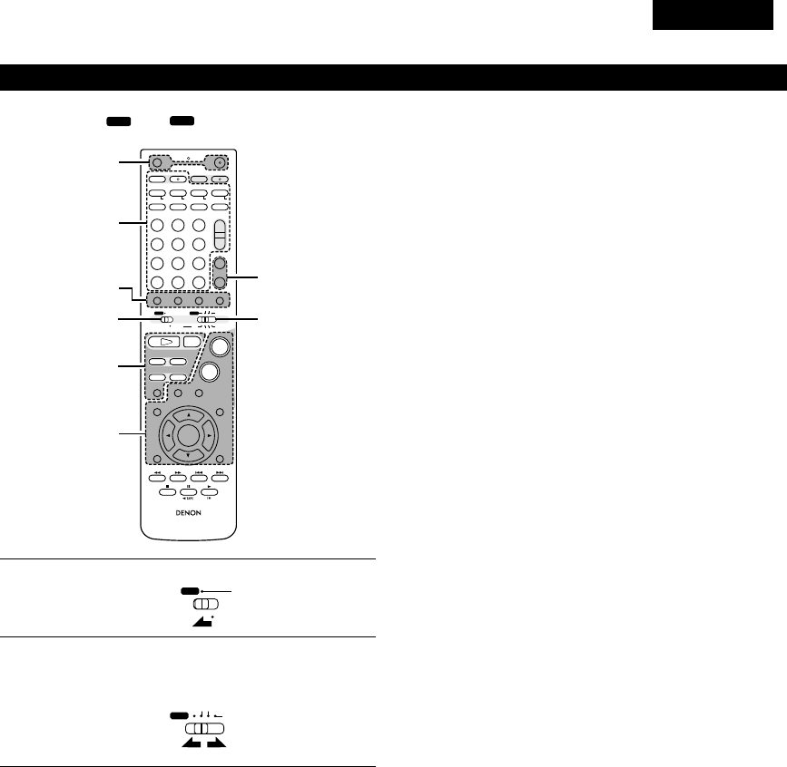
DEUTSCH
129
Bauteilbezeichnungen und Funktionen der Fernbedienungstasten am ADV-M71
•Die Tasten in den Abschnitten q~ esind unabhängig von der Position der Modus-Schalter 1 und 2 in Funktion.
•Betrachten Sie und als Standard-Positionen und schalten Sie die Position je nach Bedarf um.
DVD
A / V
+
-
+
-
RC-966
A / V
3
A-B REPEAT
SEARCH MODE
ONOFF
REPEAT RANDOM
CLEAR ZOOMSLIDE MODE
PROG/ DIRECT
MEMO BANDMODE
STAT US
RETURN
ANGLE AUDIO
SUB TITLE
SETUP TONE /SDB
FUNCTIONSURROUNDINPUT MODETEST TONE
DVD
TUNER
CH
3
-
+
21
654
987
0/10
CALL
ENTER
MUTING
+10
DISPLAY MENU
TOP MENU
SYSTEM MD
CDR TAPE
TUNER TV / VCR
SURROUND
PARAMETER
CH SELECT
VCR
NTSC/PAL
SLEEP
ENTER
CD SRS
EDIT/MENUCHARAC.
REC
TIMETITLE
TUNING /
TV VOL
TV CH TV CH
TUNERDVD
MD/ LINE-1 TAPE/ LINE-2
AUTO DECODE
VIRTUALDIRECT
5CH STEREO
STEREO
D.AUX
-
+
VCR CH
IN/SURR.
IN/SURR.
DVD
T VTV INSOURCE
9
8
21
76
+
-
RTCT
PTYRDS
3
12
q
w
e
q
q
1
2
Stellen Sie den Modus-Schalter 1 auf die “A/V”-Position.
Stellen Sie den Modus-Schalter 2 auf die Position der
Funktion, die Sie ausführen möchten. (DVD, TUNER oder
IN/SURR.).
A / V
SYSTEM
TUNER TV / VCR
IN/SURR.
DVD
qBedienungstasten des Surround-Verstärkers
ON : Zum Einschalten der Stromversorgung des
ADV-M71.
OFF : Zum Ausschalten der Stromversorgung des
ADV-M71.
FUNCTION : Zum Auswählen der Funktion (nacheinander)
SURROUND : Zum Auswählen des Surround-Modus
INPUT MODE : Zum Auswählen des Eingangsmodus
TEST TONE : Zum Ein-/Ausschalten des Testtons
+ : Zum Erhöhen der Hauptlautstärke
–: Zum Senken der Hauptlautstärke
MUTING : Zum Ein-/Ausschalten der Stummschaltung
STATUS : Zum Auswählen der Statusanzeige
TONE/SDB : Zum Auswählen und Einstellen von Klang/DSB
SURROUND : Zum Auswählen und Einstellen der Surround-
PARAMETER Parameter
SET UP : Zum Ein-/Ausschalten des Setup-Modus
CH SELECT : Zum Auswählen und Einstellen des Kanalpegels
•, ª, 0, 1: Cursor nach oben, nach unten, nach links und nach
rechts
ENTER : Zum Eingeben der Einstellung
wDVD-Bedienungstasten
1: Wiedergabe (automatisches Einschalten der
Stromversorgung und automatische Funktionswahl)
2: Stopp
8, 9:Überspringen (Suche mit Bild)
6, 7: Suche (Schnellrücklauf und Schnellvorlauf)
3: Pause und Bild-für-Bild
eTuner-Bedienungstasten
CH +/–: Vorwahlkanal auf/ab (automatisches Strom-
Einschalten und automatische Funktionswahl)

DEUTSCH
130
3Bedienung des ADV-M71.
[1] Surround-Verstärker-Systemtasten (sind in Funktion,
wenn der Modus-Schalter 2 auf “IN/SURR” gestellt
ist)
•Für die Ausführung dieser Funktionen ist die Position
des Modus-Schalters 1 unerheblich.
Die in Grau dargestellten Funktionen können
ausgeführt werden.
+
-
+
-
RC-966
A / V
3
A-B REPEAT
SEARCH MODE
ONOFF
REPEAT RANDOM
CLEAR ZOOMSLIDE MODE
PROG/ DIRECT
MEMO BANDMODE
STAT US
RETURN
ANGLE AUDIO
SUB TITLE
SETUP TONE /SDB
FUNCTIONSURROUNDINPUT MODETEST TONE
DVD
TUNER
CH
3
-
+
21
654
987
0/10
CALL
ENTER
MUTING
+10
DISPLAY MENU
TOP MENU
SYSTEM MD
CDR TAPE
TUNER TV / VCR
SURROUND
PARAMETER
CH SELECT
VCR
NTSC/PAL
SLEEP
ENTER
CD SRS
EDIT/MENUCHARAC.
REC
TIMETITLE
TUNING /
TV VOL
TV CH TV CH
TUNERDVD
MD/ LINE-1 TAPE/ LINE-2
AUTO DECODE
VIRTUALDIRECT
5CH STEREO
STEREO
D.AUX
-
+
VCR CH
IN/SURR.
IN/SURR.
DVD
T VTV INSOURCE
9
8
21
76
+
-
RTCT
PTYRDS
SLEEP : Zum Ein-/Ausschalten der Einschlaf-
Funktion
DVD : DVD-Funktion
TUNER : TUNER-Funktion
D.AUX : D.AUX-FunktionMD/LINE-1-Funktion
MD/LINE-1 : MD/LINE-1-Funktion
TAPE/LINE-2 : TAPE/LINE-2-Funktion
5CH STEREO : 5-Kanal-Stereo-Surround-Modus (wenn im
Setup “5.1 CH” ausgewählt wurde)
AUTO DECODE
: 2-Kanal-Modus-Umschaltung, wenn der
automatische Entschlüsselungs-Surround-
Modus eingestellt ist (wenn im Setup
“5.1CH” ausgewählt wurde)
VIRTUAL : 2-Kanal-Modus-Umschaltung, wenn der
Dolby Virtual Speaker- oder Dolby VS-
Surround-Modus eingestellt ist
STEREO : Stereo-Modus
DIRECT : Direkt-Modus
[2] DVD-Systemtasten (sind in Funktion, wenn der
Modus-Schalter 2 auf “DVD” gestellt ist)
+
-
+
-
RC-966
A / V
3
A-B REPEAT
SEARCH MODE
ONOFF
REPEAT RANDOM
CLEAR ZOOMSLIDE MODE
PROG/ DIRECT
MEMO BANDMODE
STAT US
RETURN
ANGLE AUDIO
SUB TITLE
SETUP TONE /SDB
FUNCTIONSURROUNDINPUT MODETEST TONE
DVD
TUNER
CH
3
-
+
21
654
987
0/10
CALL
ENTER
MUTING
+10
DISPLAY MENU
TOP MENU
SYSTEM MD
CDR TAPE
TUNER TV / VCR
SURROUND
PARAMETER
CH SELECT
VCR
NTSC/PAL
SLEEP
ENTER EDIT/MENUCHARAC.
REC
TIMETITLE
TUNING /
TV VOL
TV CH TV CH
TUNERDVD
MD/ LINE-1 TAPE/ LINE-2
AUTO DECODE
VIRTUALDIRECT
5CH STEREO
STEREO
D.AUX
-
+
VCR CH
IN/SURR.
IN/SURR.
DVD
T VTV INSOURCE
9
8
21
76
+
-
CD SRS
RTCT
PTYRDS
NTSC/PAL : Zum Auswählen von NTSC/PAL
ZOOM : Zum Ein-/Ausschalten des Zooms
SLIDE MODE : Zum Auswählen des JPEG-Bild-Dia-Modus
A-B REPEAT : Zur Einstellung der A-B-
Wiedergabewiederholung
CLEAR : Zum Löschen eines Programms
SEARCH MODE
: Zum Auswählen der Spur- und
Kapitelsuche
RANDOM : Zum Ein-/Ausschalten der
Zufallswiedergabe
REPEAT : Zur Einstellung der
Wiedergabewiederholung
PROG/DIRECT : Zum Auswählen der
programmierten/direktenWiedergabe
CALL : Zum Aufrufen eines Programms
0 ~ 9, +10 : Zifferntasten
TOP MENU : Zum Aufrufen des Top-Menüs
MENU : Zum Aufrufen von Menüs
DISPLAY : Zum Anzeigen des Aufrufes/der Auswahl
RETURN : Zum Zurückkehren zum Menü
SUBTITLE : Zum Auswählen der Untertitelsprache
AUDIO : Zum Auswählen der Audiosprache
ANGLE : Zum Auswählen des Winkels

DEUTSCH
131
3[3] Tuner-Systemtasten (sind in Funktion, wenn der
Modus-Schalter 2 auf “TUNER” gestellt ist)
+
-
+
-
RC-966
A / V
3
A-B REPEAT
SEARCH MODE
ONOFF
REPEAT RANDOM
CLEAR ZOOMSLIDE MODE
PROG/ DIRECT
MEMO BANDMODE
STAT US
RETURN
ANGLE AUDIO
SUB TITLE
SETUP TONE /SDB
FUNCTIONSURROUNDINPUT MODETEST TONE
DVD
TUNER
CH
3
-
+
21
654
987
0/10
CALL
ENTER
MUTING
+10
DISPLAY MENU
TOP MENU
SYSTEM MD
CDR TAPE
TUNER TV / VCR
SURROUND
PARAMETER
CH SELECT
VCR
NTSC/PAL
SLEEP
ENTER EDIT/MENUCHARAC.
REC
TIMETITLE
TUNING /
TV VOL
TV CH TV CH
TUNERDVD
MD/ LINE-1 TAPE/ LINE-2
AUTO DECODE
VIRTUALDIRECT
5CH STEREO
STEREO
D.AUX
-
+
VCR CH
IN/SURR.
IN/SURR.
DVD
T VTV INSOURCE
9
8
21
76
+
-
CD SRS
RTCT
PTYRDS
BAND : Zum Auswählen des UKW-/MW-
Frequenzbereiches
MEMO : Vorwahlspeicher
MODE : Zum Auswählen des UKW-Auto-/Mono-
Modus
TUNER +/–: Senderabstimmung auf/ab
1 ~ 10, +10 : Vorwahlkanal-Zifferntasten
RDS PTY TP
1 1 1
OFF 0
PTY : Drücken Sie diese Taste, nachdem Sie mit der RDS-
Taste “PTY” ausgewählt haben, um eine der 29
Programmsparten auszuwählen.
CT : Korrigieren Sie mit dieser Taste die Uhrzeit am ADV-
M71. Drücken Sie diese Taste, wenn der Uhrzeit-
Service eines RDS-Senders einwandfrei empfangen
wird. “TIME” wird für 2 Sekunden angezeigt und
die Uhr des ADV-M71 wird korrigiert. “NO TIME
DATA” wird angezeigt, wenn der RDS-Sender
keinen Uhrzeit-Service unterstützt und der Empfang
nicht einwandfrei ist.
RT : Drücken Sie beim Empfang von RDS-Sendern diese
Taste, um die Frequenz-, PS- (oder Sendername),
PTY- oder RT-Anzeige auszuwählen.
Beachten Sie, dass diese Taste bei schlechtem
Empfang außer Funktion ist.
Bei jedem Drücken der Taste ändert sich der
Anzeigemodus wie folgt.
RDS : Stimmen Sie mit dieser Taste Sender automatisch
mit Hilfe des Radiodatensystems ab.
PS (oder Sendername) RT PTY
1 1 1
Frequency 0
Anstatt der PS-Anzeige wird vorrangig der Sendername
angezeigt, wenn ein Sender abgestimmt wird, dessen
Sendername vorprogrammiert wurde.

DEUTSCH
132
9FERNBEDIENUNGSGERÄT
•Mit dem mitgelieferten Fernbedienungsgerät (RC-966) kann nicht nur der ADV-M71 sondern es können auch andere zur Fernbedienung
ausgelegte DENON-Komponenten gesteuert werden. Zusätzlich beinhaltet der Speicher die Steuersignale für andere Fernbedienungsgeräte, so
dass damit auch fernbedienbare Geräte betrieben werden können, die nicht von Denon hergestellt wurden.
(1) Einlegen der Batterien
qEntfernen Sie die rückwärtige Abdeckung des
Fernbedienungsgerätes.
wLegen Sie die drei R6P/AA-Batterien in der angegebenen Richtung
in das Batteriefach ein.
eSetzen Sie die rückwärtige Abdeckung wieder auf.
Hinweise zu Batterien
•Verwenden Sie im Fernbedienungsgerät R6P/AA-Batterien.
•Die Batterien sollten ca. einmal jährlich gegen neue ausgetauscht
werden. Wie oft ein Batteriewechsel jedoch tatsächlich erforderlich
ist, hängt von der Häufigkeit der Benutzung des
Fernbedienungsgerätes ab.
•Tauschen Sie die Batterien auch vor Ablauf eines Jahres aus, wenn
sich das Gerät selbst aus nächster Entfernung nicht mit dem
Fernbedienungsgerät bedienen läßt. (Die mitgelieferte Batterie ist
ausschließlich für Testzwecke vorgesehen. Tauschen Sie die
Batterie so bald wie möglich aus.)
•Achten Sie beim Einlegen der Batterien unbedingt auf die richtige
Ausrichtung der Polaritäten. Folgen Sie den “<” und “>” Zeichen
im Batteriefach.
•Um Beschädigungen oder ein Auslaufen von Batterieflüssigkeit zu
vermeiden:
•Verwenden Sie keine neuen und alten Batterien zusammen.
•Verwenden Sie keine verschiedenen Batterietypen gleichzeitig.
•Schließen Sie Batterien nicht kurz, zerlegen und erhitzen Sie sie
nicht und werfen Sie Batterien niemals in offenes Feuer.
•Nehmen Sie die Batterien aus dem Fernbedienungsgerät heraus,
wenn Sie beabsichtigen, es über einen längeren Zeitraum hinweg
nicht zu benutzen.
•Sollte einmal Batterieflüssigkeit ausgelaufen sein, so wischen Sie
das Batteriefach sorgfältig aus und legen Sie neue Batterien ein.
•Beim Austauschen der Batterien sollten Sie sofort neue Batterien
zur Hand haben und diese so schnell wie möglich einlegen.
(2) Fernbedienungsbetrieb
B
+
-
+
-
RC-936
A / V
3
A-B REPEAT
SEARCH MODE
ON
OFF
REPEATRANDOM
CLEARZOOM
SLIDE MODE
PROG/DIRECT
MEMOBAND
MODE
ST
A
TUS
RETURN
ANGLEAUDIO
SUB TITLE
SETUPTONE/SDB
FUNCTION
SURROUND
INPUT MODE
TEST TONE
DVD
TUNER
CH
3
-
+
2
1
6
5
4
9
8
7
0
/10
CALL
ENTER
MUTING
+10
DISPLAYMENU
TOP MENU
SYSTEMMD
CDRT
APE
TUNERTV / VCR
SURROUND
PARAMETER
CH SELECT
VCR
NTSC/PAL
SLEEP
ENTER
CD SRS
EDIT/MENU
CHARAC.
REC
TIME
TITLE
TUNING /
TV VOL
TV CHTV CH
TUNER
DVD
MD/LINE-1T
APE/LINE-2
AUTO DECODE
VIRTUAL
DIRECT
5CH STEREO
STEREO
D.AUX
-
+
VCR CH
IN/SURR.
IN/SURR.
DVD
T V
TV IN
SOURCE
+
-
9
8
21
7
6
•Richten Sie das Fernbedienungsgerät - wie im Diagramm gezeigt -
auf den Fernbedienungssensor am Hauptgerät.
•Die Reichweite des Fernbedienungsgerätes beträgt aus gerader
Entfernung vom Hauptgerät ca. 7 Meter./22 Fuß Diese Entfernung
verkürzt sich jedoch, wenn Gegenstände im Weg liegen oder das
Fernbedienungsgerät nicht direkt auf den Fernbedienungssensor
gerichtet wird.
•Das Fernbedienungsgerät kann in einem horizontalen Winkel von
bis zu 30 Grad zum Fernbedienungssensor betrieben werden.
HINWEISE:
•Der Betrieb des Fernbedienungsgerätes ist möglicherweise
schwierig, wenn der Fernbedienungssensor direktem Sonnenlicht
oder starkem künstlichem Licht ausgesetzt ist.
•Drücken Sie keine Tasten am Hauptgerät und auf dem
Fernbedienungsgerät gleichzeitig, da dies in einer Fehlfunktion
resultieren würde.
•Neonschilder oder andere sich in der Nähe befindliche impulsartige
Störungen ausstrahlende Geräte können Fehlfunktionen
verursachen. Halten Sie die Anlage soweit wie möglich von
derartigen Einrichtungen fern.
Ca. 7 m/22 Fuß
30°
30°
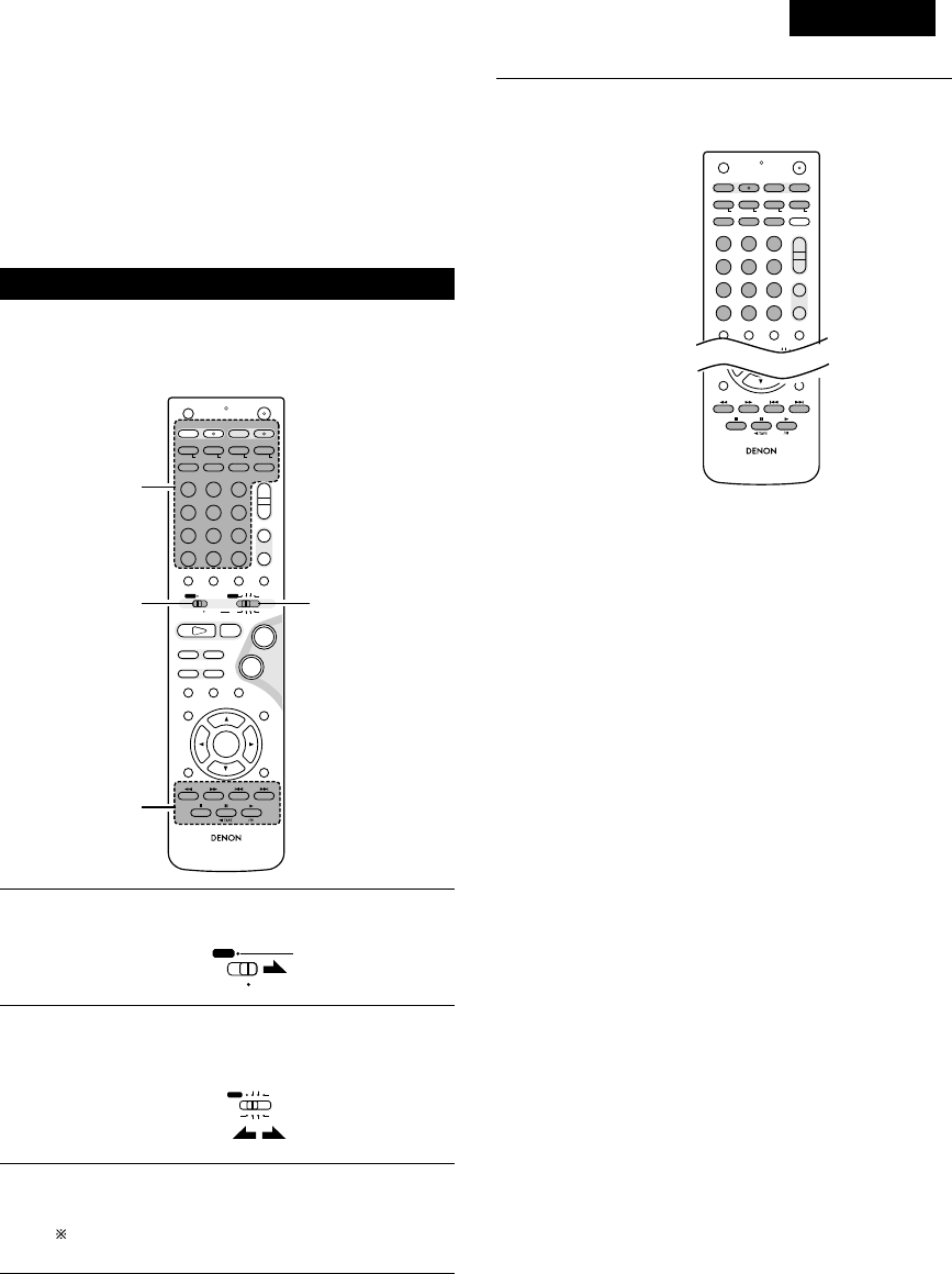
DEUTSCH
133
•Mit der im Lieferumfang enthaltenen Fernbedienung (RC-966) kann
nicht nur der ADV-M71, sondern können auch die
Systemfunktionen für Geräte der D-M31-Serie gesteuert werden.
Darüber hinaus ist mit dieser Fernbedienung der Betrieb von
anderen zur Fernbedienung ausgelegten DENON-Komponenten
möglich. Zusätzlich beinhaltet der Speicher die Fernbedienungs-
Befehlscodes von anderen großen Fernsehgerät- und Videodeck-
Herstellern, so dass auch diese Geräte mit dieser Fernbedienung
gesteuert werden können.
(3) Bedienung der DENON-Audiokomponenten
•Schalten Sie vor der Inbetriebnahme die Stromversorgung aller
Komponenten ein.
•Je nach Modell und Herstellungsjahr Ihrer Komponente sind einige
Tasten möglicherweise nicht funktionsfähig.
+
-
+
-
RC-966
A / V
3
A-B REPEAT
SEARCH MODE
ONOFF
REPEAT RANDOM
CLEAR ZOOMSLIDE MODE
PROG/ DIRECT
MEMO BANDMODE
STAT US
RETURN
ANGLE AUDIO
SUB TITLE
SETUP TONE /SDB
FUNCTIONSURROUNDINPUT MODETEST TONE
DVD
TUNER
CH
3
-
+
21
654
987
0/10
CALL
ENTER
MUTING
+10
DISPLAY MENU
TOP MENU
SYSTEM MD
CDR TAPE
TUNER TV / VCR
SURROUND
PARAMETER
CH SELECT
VCR
NTSC/PAL
SLEEP
ENTER EDIT/MENUCHARAC.
REC
TIMETITLE
TUNING /
TV VOL
TV CH TV CH
TUNERDVD
MD/ LINE-1 TAPE/ LINE-2
AUTO DECODE
VIRTUALDIRECT
5CH STEREO
STEREO
D.AUX
-
+
VCR CH
IN/SURR.
IN/SURR.
DVD
T VTV INSOURCE
9
8
21
76
+
-
CD SRS
RTCT
PTYRDS
3
12
3
1
2
3
Stellen Sie den Modus-Schalter 1 auf die “SYSTEM”-Position
(in Blau dargestellt).
Stellen Sie den Modus-Schalter 2 auf die Position für die zu
bedienende Komponente (MD, CDR oder TAPE)
(in Blau dargestellt).
Betreiben Sie die Audiokomponente.
•Lesen Sie hinsichtlich der Einzelheiten die
Bedienungsanleitung der Komponente.
Einige Modelle können möglicherweise nicht betrieben
werden.
A / V
SYSTEM
MD
CDR TAPE
TUNER TV / VCR
IN/SURR.
IN/SURR.
DVD
3[1] MD-Recorder-Systemtasten
(sind in Funktion, wenn der Modus-Schalter 2 auf “MD”
gestellt ist)
+
-
+
-
A/V
A-B REPEAT
SEARCH MODE
ONOFF
REPEAT RANDOM
CLEAR ZOOMSLIDE MODE
PROG/ DIRECT
MEMO BANDMODE
FUNCTIONSURROUNDINPUT MODETEST TONE
TUNER
CH
3
-
+
21
654
987
0/10
CALL
+10
TUNER TV / VCR
VCR
NTSC/PAL
SLEEP
ENTER
CD SRS
EDIT/MENUCHARAC.
REC
TIMETITLE
TUNING /
TV VOL
TV CH TV CH
TUNERDVD
MD/ LINE-1 TAPE/ LINE-2
AUTO DECODE
VIRTUALDIRECT
5CH STEREO
STEREO
D.AUX
IN/SURR
DVD
T VTV INSOURCE
RTCT
PTYRDS
TIME : Zum Anzeigen der Disc-Spielzeit
TITLE : Zum Anzeigen des Namens
REC : Für die Aufnahme (Multi-Aufnahmefunktion mit
dem DMD-M31)
SOURCE : Zum Ein-/Ausschalten der MD-Recorder-
Stromversorgung
EDIT/MENU : Zum Auswählen des Bearbeitungsmodus
CHARAC : Zum Auswählen der Zeichen bei der
Namenseingabe
ENTER : Zum Eingeben von bearbeiteten Werten
CD SRS : CD-synchronisierte Aufnahme (DMD-M31-
Systemfunktion)
CLEAR : Zum Löschen eines Programms
RANDOM : Zum Ein-/Ausschalten der Zufallswiedergabe
REPEAT : Zum Einstellen der Wiedergabewiederholung
PROG/DIRECT : Zum Auswählen der programmierten/direkten
Wiedergabe
CALL : Zum Aufrufen eines Programms
1~10, +10 : Zum Auswählen einer Spurnummer
8, 9: Automatik-Suche (Suche mit Bild)
6, 7: Manuelle Suche (Schnellrücklauf und
Schnellvorlauf)
1(/ 3) : Wiedergabe (Wiedergabe/Pause, automatisches
Strom-Einschalten und automatische
Funktionswahl mit dem DMD-M31)
3: Pause
2: Stopp
RC-966
RETURN
ANGLE AUDIO
SUB TITLE
DISPLAY MENU
TOP MENU
SURROUND
PARAMETER
CH SELECT
-
+
VCR CH

DEUTSCH
134
[2] CD-Recorder-Systemtasten
(sind in Funktion, wenn der Modus-Schalter 2 auf “CDR”
gestellt ist)
+
-
+
-
A/V
A-B REPEAT
SEARCH MODE
ONOFF
REPEAT RANDOM
CLEAR ZOOMSLIDE MODE
PROG/ DIRECT
MEMO BANDMODE
FUNCTIONSURROUNDINPUT MODETEST TONE
TUNER
CH
3
-
+
21
654
987
0/10
CALL
+10
TUNER TV / VCR
VCR
NTSC/PAL
SLEEP
ENTER
CD SRS
EDIT/MENUCHARAC.
REC
TIMETITLE
TUNING /
TV VOL
TV CH TV CH
TUNERDVD
MD/ LINE-1 TAPE/ LINE-2
AUTO DECODE
VIRTUALDIRECT
5CH STEREO
STEREO
D.AUX
IN/SURR
DVD
T VTV INSOURCE
RTCT
PTYRDS
TIME : Zum Anzeigen der Disc-Spielzeit
TITLE : Zum Anzeigen des Namens und zum Auswählen
von Zeichen bei der Namenseingabe
REC : Für die Aufnahme
SOURCE : Zum Ein-/Ausschalten der CD-Recorder-
Stromversorgung
EDIT/MENU : Zum Auswählen der Menüs
ENTER : Zum Eingeben von Menüfunktionen
CLEAR : Zum Löschen eines Programms
RANDOM : Zum Ein-/Ausschalten der Zufallswiedergabe
REPEAT : Zur Einstellung der Wiedergabewiederholung
PROG/DIRECT : Zum Auswählen der programmierten/direkten
Wiedergabe
CALL : Zum Aufrufen eines Programms
1~10, +10 : Zum Auswählen einer Spurnummer
8, 9: Automatik-Suche (mit Bild)
6, 7: Manuelle Suche (Schnellrücklauf und
Schnellvorlauf))
1(/ 3) : Wiedergabe (Wiedergabe/Pause, automatische
Strom-Einschaltung und automatische
Funktionswahl mit dem CDR-M30)
3: Pause
2: Stopp
[3] Kassettendeck-Systemtasten
(sind in Funktion, wenn der Modus-Schalter 2 auf “TAPE”
gestellt ist)
A-B REPEAT
SEARCH MODE
ONOFF
REPEAT RANDOM
CLEAR ZOOMSLIDE MODE
PROG/ DIRECT
MEMO BANDMODE
-
+
VCR
NTSC/PAL
SLEEP
ENTER
CD SRS
EDIT/MENUCHARAC.
REC
TIMETITLE
TUNING /
TV VOL
TV CH TV CH
TUNERDVD D.AUX
T VTV INSOURCE
RTCT
PTYRDS
REC : Für die Aufnahme
CD SRS : CD-synchronisierte Aufnahme (DRR-M31-
Systemfunktion)
6, 7:Für den Rücklauf und Schnellvorlauf
1:Für die Vorwärts-Wiedergabe
0TAPE : Für die Rückwärts-Wiedergabe (0und 1
automatisches Strom-Einschalten und
automatische Funktionswahl mit dem DRR-M31)
RC-966
RETURN
ANGLE AUDIO
SUB TITLE
DISPLAY MENU
TOP MENU
SURROUND
PARAMETER
CH SELECT
-
+
VCR CH
RC-966
RETURN
ANGLE AUDIO
SUB TITLE
DISPLAY MENU
TOP MENU
SURROUND
PARAMETER
CH SELECT
-
+
VCR CH

DEUTSCH
135
(4) Fernsehgerät- und Videodeck-Vorwahlspeicher
•Mit der im Lieferumfang enthaltenen Fernbedienung können
Komponenten von anderen Herstellern betrieben werden, indem
ihre entsprechenden Codes im Vorwahlspeicher gespeichert
werden.
Beachten Sie, dass je nach Modell möglicherweise einige
Funktionen nicht ausgeführt werden können und dass einige Tasten
unter Umständen nicht einwandfrei funktionieren.
+
-
+
-
RC-966
A / V
3
A-B REPEAT
SEARCH MODE
ONOFF
REPEAT RANDOM
CLEAR ZOOMSLIDE MODE
PROG/ DIRECT
MEMO BANDMODE
STAT US
RETURN
ANGLE AUDIO
SUB TITLE
SETUP TONE /SDB
FUNCTIONSURROUNDINPUT MODETEST TONE
DVD
TUNER
CH
3
-
+
21
654
987
0/10
CALL
ENTER
MUTING
+10
DISPLAY MENU
TOP MENU
SYSTEM MD
CDR TAPE
TUNER TV / VCR
SURROUND
PARAMETER
CH SELECT
VCR
NTSC/PAL
SLEEP
ENTER EDIT/MENUCHARAC.
REC
TIMETITLE
TUNING /
TV VOL
TV CH TV CH
TUNERDVD
MD/ LINE-1 TAPE/ LINE-2
AUTO DECODE
VIRTUALDIRECT
5CH STEREO
STEREO
D.AUX
-
+
VCR CH
IN/SURR.
IN/SURR.
DVD
T VTV INSOURCE
9
8
21
76
+
-
CD SRS
RTCT
PTYRDS
4
33
4
4
12
2Keine Werkseinstellungen.
1
2
3
4
Stellen Sie den Modus-Schalter 1 auf die “A/V”-Position.
Stellen Sie den Modus-Schalter 2 auf die “TV/VCR”-Position.
Drücken Sie gleichzeitig die Netztasten ON und OFF.
•Das Übertragungs-LED (Anzeige) blinkt.
Drücken Sie zur Vorprogrammierung eines Fernsehgerätes
die TV-Taste, zur Vorprogrammierung eines Videodecks die
VCR-Taste, und geben Sie dann die 3-stellige Zahl
entsprechend des Herstellers der Komponente ein, deren
Signale Sie im Vorwahlspeicher speichern möchten (sehen
Sie sich dazu die Tabelle der Fernbedienungscodes auf den
Seiten 136 bis 139 an).
A / V
SYSTEM
MD
CDR TAPE
TUNER TV / VCR
IN/SURR.
IN/SURR.
DVD
OFF ON
TIME
T V
HINWEISE:
•Wenn Sie während der Einstellung des Vorwahlspeichers eine
Taste drücken, werden deren Signale vom
Fernbedienungssensor gesendet. Sie sollten den
Fernbedienungssensor daher bei der Einstellung des
Vorwahlspeichers abdecken, um eine versehentliche Bedienung
zu vermeiden.
•Je nach Modell und Herstellungsjahr funktionieren einige
Fernbedienungscodes für die in der Tabelle aufgeführten
Hersteller möglicherweise nicht einwandfrei.
•Bei einigen Herstellern gibt es mehrere Arten von
Fernbedienungscodes. Falls eine Bedienung nicht funktioniert,
versuchen Sie es noch einmal mit einem der anderen Codes.
VCR
NTSC/PAL
REC
321
654
987
0/10
TUNERDVD
MD/ LINE-1 TAPE/ LINE-2
AUTO DECODE5CH STEREO
STEREO
D.AUX

DEUTSCH
136
Combinations of preset codes for different brands
Fujitsu 004, 062
Funai 004, 062
Futuretech 004
GE 020, 036, 037, 040, 044, 058, 066, 088, 119, 120,
125, 147
Goldstar 015, 029, 031, 039, 048, 051, 056, 057, 067,
068, 069, 116, 165
Grundy 062
Hitachi 029, 031, 051, 052, 070, 111, 112, 113, 124, 134
Hitachi Pay TV 151
Infinity 017, 071
Janeil 122
JBL 017, 071
JC Penny 020, 034, 039, 040, 041, 044, 048, 050,058, 066,
069, 076, 088, 090, 095, 125, 136, 159
JCB 046
JVC 019, 051, 052, 072, 073, 091, 117, 126
Kawasho 018, 046
Kenwood 038, 056, 057
Kloss 010, 032
Kloss Novabeam 005, 122, 127, 131
KTV 074, 123
Loewe 071
Logik 144
Luxman 031
LXI 008, 014, 017, 024, 040, 044, 063, 071, 075, 076,
077, 118, 125
Magnavox 005, 010, 017, 030, 033, 038, 050, 056, 071, 078,
079, 085, 089, 108, 109, 110, 127, 131, 132, 145
Marantz 015, 017, 071, 080
Matsui 027
Memorex 014, 027, 045, 083, 118, 144
Metz 160, 161, 162, 163, 164
MGA 001, 039, 048, 056, 057, 058, 065 081, 083
Midland 125
Minutz 066
Mitsubishi 001, 016, 039, 048, 056, 057, 058, 065, 081, 082,
083, 105
Montgomery Ward
011, 020, 144, 145, 146
Motorola 121, 147
MTC 031, 034, 039, 048, 095
NAD 008, 075, 076, 128
National 002, 036, 061, 147
TV
Admiral 045, 121
Adventura 122
Aiko 054
Akai 016, 027, 046
Alleron 062
A-Mark 007
Amtron 061
Anam 006, 007, 036
Anam National 061, 147
AOC 003, 007, 033, 038, 039, 047, 048, 049, 133
Archer 007
Audiovox 007, 061
Bauer 155
Belcor 047
Bell & Howell 045, 118
Bradford 061
Brockwood 003, 047
Candle 003, 030, 031, 032, 038, 047, 049, 050, 122
Capehart 003
Celebrity 046
Circuit City 003
Citizen 029, 030, 031, 032, 034, 038, 047, 049, 050, 054,
061, 095, 122, 123
Concerto 031, 047, 049
Colortyme 003, 047, 049, 135
Contec 013, 051, 052, 061
Cony 051, 052, 061
Craig 004, 061
Crown 029
Curtis Mathes 029, 034, 038, 044, 047, 049, 053, 095, 118
Daewoo 027, 029, 039, 048, 049, 054, 055, 106, 107, 137
Daytron 003, 049
Dimensia 044
Dixi 007, 015, 027
Electroband 046
Electrohome 029, 056, 057, 058, 147
Elta 027
Emerson 029, 051, 059, 060, 061, 062, 118, 123, 124, 139, 148
Envision 038
Etron 027
Fisher 014, 021, 063, 064, 065, 118
Formenti 155
Fortress 012

DEUTSCH
138
VCR
Admiral 081
Aiko 095
Aiwa 009
Akai 026, 027, 070, 072, 082, 083, 084
Alba 055
Amstrad 009
ASA 042
Asha 087
Audio Dynamic 005, 085
Audiovox 088
Beaumark 087
Broksonic 086, 093
Calix 088
Candle 006, 087, 088, 089, 090
Canon 049, 057
Capehart 025, 055, 056, 071
Carver 015
CCE 095
Citizen 006, 007, 087, 088, 089, 090, 095
Craig 007, 087, 088, 091, 115
Curtis Mathes 006, 049, 073, 080, 087, 090, 092
Cybernex 087
Daewoo 025, 055, 059, 074, 089, 093, 095, 096
Daytron 025, 055
DBX 005, 085
Dumont 053
Dynatech 009
Electrohome 001, 088, 097
Electrophonic 088
Emerson 001, 009, 017, 027, 086, 088, 089, 092, 093, 097,
100, 101, 102, 103, 104, 117
Fisher 009, 028, 031, 053, 054, 091, 098, 099, 115
GE 007, 011, 049, 050, 051, 052, 073, 080, 087
Go Video 047, 048
Goldstar 006, 012, 062, 088, 129
Gradiente 094
Grundig 042
Harley Davidson 094
Harman Kardon 040, 062
Hi-Q 091
Hitachi 009, 013, 023, 026, 058, 108, 109, 110, 111
JC Penny 004, 005, 007, 023, 028, 049, 062,
085, 087, 088
Jensen 013, 026
JVC 004, 005, 006, 026, 029, 043, 044, 045, 046, 085
Kenwood 004, 005, 006, 026, 029, 033, 045, 085, 090
Kodak 088
Lloyd 009, 094
LXI 088
Magnavox 015, 016, 042, 049, 063, 106
Magnin 087
Marantz 004, 005, 006, 015, 042, 049, 085, 090
Marta 088
MEI 049
Memorex 009, 033, 049, 053, 060, 081, 087, 088, 091, 094,
115
Metz 123, 124, 125, 126, 127, 128
MGA 001, 017, 027, 041, 097
MGN Technology 087
Midland 011
Minolta 013, 023
Mitsubishi 001, 003, 008, 013, 014, 017, 027, 029, 039, 040,
041, 045, 097
Motorola 081
Montgomery Ward
001, 002, 007, 009, 049, 063, 081, 115, 117
MTC 009, 087, 094
Multitech 007, 009, 011, 087, 090, 094
NAD 038
NEC 004, 005, 006, 018, 026, 029, 045, 061, 062, 085
Nikko 088
Noblex 087
Optimus 081, 088
Optonica 021
Panasonic 024, 049, 064, 066, 067, 068, 069, 107
Perdio 009
Pentax 006, 013, 023, 058, 090
Philco 015, 016, 049
Philips 015, 021, 042, 049, 105
Pilot 088
Pioneer 005, 013, 029, 036, 037, 038, 045, 085
Portland 025, 055, 090
Proscan 063, 080
Pulsar 060
Quartz 033
Quasar 034, 035, 049
Radio Shack 001, 002, 021, 081, 087, 088, 091, 094, 097, 098,
115
Radix 088

DEUTSCH
139
Randex 088
RCA 007, 013, 019, 023, 058, 063, 064, 065, 073, 080,
082, 087
Realistic 009, 021, 031, 033, 049, 053, 081, 087, 088, 091,
094, 097, 098
Ricoh 055
Salora 033, 041
Samsung 007, 011, 051, 059, 070, 083, 087, 089, 113
Sanky 081
Sansui 005, 026, 029, 045, 061, 085, 114
Sanyo 032, 033, 053, 087, 091, 115, 116
SBR 042
Scott 017, 020, 086, 089, 093, 117
Sears 013, 023, 028, 031, 033, 053, 054, 088, 091, 098,
099, 115
Sentra 055
Sharp 001, 002, 021, 097
Shogun 087
Sony 075, 076, 077, 078, 079, 121, 122
STS 023
Sylvania 009, 015, 016, 017, 041, 049, 094
Symphonic 009, 094
Tandy 009
Tashiko 009, 088
Tatung 004, 026, 030
Teac 004, 009, 026, 094
Technics 024, 049
Teknika 009, 010, 022, 049, 088, 094
TMK 087, 092
Toshiba 013, 017, 020, 041, 059, 089, 098, 099, 117
Totevision 007, 087, 088
Unirech 087
Vecrtor Research 005, 062, 085, 089, 090
Victor 005, 045, 046, 085
Video Concepts 005, 027, 085, 089, 090
Videosonic 007, 087
Wards 013, 021, 023, 087, 088, 089, 091, 094, 097, 118,
119, 120
XR-1000 094
Yamaha 004, 005, 006, 026, 062, 085
Zenith 060, 078, 079

DEUTSCH
140
(5) Bedienung des Fernsehgerätes/Videodecks nach dem Speichern der Fernbedienungssignale im
Vorwahlspeicher
+
-
+
-
RC-966
A / V
3
A-B REPEAT
SEARCH MODE
ONOFF
REPEAT RANDOM
CLEAR ZOOMSLIDE MODE
PROG/ DIRECT
MEMO BANDMODE
STAT US
RETURN
ANGLE AUDIO
SUB TITLE
SETUP TONE /SDB
FUNCTIONSURROUNDINPUT MODETEST TONE
DVD
TUNER
CH
3
-
+
21
654
987
0/10
CALL
ENTER
MUTING
+10
DISPLAY MENU
TOP MENU
SYSTEM MD
CDR TAPE
TUNER TV / VCR
SURROUND
PARAMETER
CH SELECT
VCR
NTSC/PAL
SLEEP
ENTER EDIT/MENUCHARAC.
REC
TIMETITLE
TUNING /
TV VOL
TV CH TV CH
TUNERDVD
MD/ LINE-1 TAPE/ LINE-2
AUTO DECODE
VIRTUALDIRECT
5CH STEREO
STEREO
D.AUX
-
+
VCR CH
IN/SURR.
IN/SURR.
DVD
T VTV INSOURCE
9
8
21
76
+
-
CD SRS
RTCT
PTYRDS
3
-q
3
-w
12
3
-w
3
-q
1
2
3
Stellen Sie den Modus-Schalter 1 auf die “A/V”-Position.
Stellen Sie den Modus-Schalter 2 auf die “TV/VCR”-Position.
Bedienen Sie die Videokomponente.
•Lesen Sie hinsichtlich der Einzelheiten die
Bedienungsanleitung der Komponente.
Einige Modelle können möglicherweise nicht bedient
werden.
A / V
SYSTEM
MD
CDR TAPE
TUNER TV / VCR
IN/SURR.
IN/SURR.
DVD
HINWEIS:
•Die “TV (POWER)”- und “TV IN”-Tasten des Fernsehgerätes
können – unabhängig von der Position des Modus-Schalters 2 -
so lange bedient werden wie der Modus-Schalter 1 auf die
“A/V”-Position gestellt ist.
3Monitor-Fernsehgerät- (TV) und Videodeck- (VCR)
Systemtasten.
qFernsehgerät-Systemtasten
TV : Zum Ein-/Ausschalten der Fernsehgerät-
Stromversorgung
0~9 : Kanalnummern
TV IN : Zum Umschalten des Fernsehgerät-Eingangs
TV VOL +, –: Zum Anheben/Senken der Lautstärke
TV CH +, –: Zum Umschalten des Kanals
wVideodeck-Systemtasten
VCR : Zum Ein-/Ausschalten der VCR-Stromversorgung
VCR CH +, –: Zum Umschalten des Kanals
6, 7:Für die manuelle Suche (Schnellvorlauf und
Schnellrücklauf)
1: Wiedergabe
3: Pause
2: Stopp

DEUTSCH
141
Speaker
2CH Virtual
Stellen Sie die Bildschirmgröße und das Lautsprechersystem
ein.
TV Aspect
4:3 PS
LINE-1 LINE-2 REC OUT
MD TAPE ON
FUNCTION ASSIGNMENT
Geben Sie die LINE-1- und LINE-2 Funktionsbezeichnungen
ein und schalten Sie den analogen Aufnahmeausgang (REC
OUT) ein oder aus.
3
STAT U S
RETURN
ANGLE AUDIO
SUB TITLE
SETUP TONE/ SDB
ENTER
MUTING
DISPLAY MENU
TOP MENU
SURROUND
PARAMETER
CH SELECT
-
+
VCR CH
76
-
10 AUFSTELLUNG DES SYSTEMS
•Wenn alle Anschlüsse mit anderen AV-Komponenten, wie im Abschnitt “ANSCHLÜSSE” (siehe Seite 120 bis 126) beschrieben, abgeschlossen
sind, nehmen Sie mittels der Bildschirmanzeigefunktion des ADV-M71’s die verschiedenen, unten auf dem Monitorbildschirm beschriebenen
Einstellungen vor.
•Richten Sie das System mit den folgenden Tasten ein:
Systemsetup-Punkte und voreingestellte Werte (werkseitig eingestellt)
Setup
QUICK SETUP
SPEAKER CONFIGURATION
DERAY TIME
CHANNEL KEVEL
AV1 VIDEO OUTPUT
DVD AUTO POWER OFF
DISC SETUP
OSD SETUP
VIDEO SETUP
AUDIO SETUP
RATINGS
DTHER SETUP
Geben Sie die Lautsprecher-Kombination und das
entsprechende Format (KLEIN für reguläre Lautsprecher,
GROSS für normale, Vollbereich) in Ihr System ein, um die
Zusammensetzung der von den Lautsprechern
ausgegebenen Signale und den Frequenzgang automatisch
einzustellen.
Dieser Parameter ist für die Optimierung des Takts
bestimmt, mit dem die Audiosignale von den Lautsprechern
und dem Subwoofer gemäß der Hörposition produziert
werden.
Hören Sie sich in der Hörposition die Prüftöne an, die von den
verschiedenen Lautsprechern ausgegeben werden, und nehmen
Sie eine solche Einstellung vor, dass der Wiedergabepegel von den
verschiedenen Lautsprechern gleich ist.
Die Stromversorgung schaltet automatisch in Bereitschaft,
wenn im Stopp-Modus und bei aktivierter DVD-Funktion 30
Minuten lang keine Bedienung erfolgt.
Für die Auswahl, ob Videomischsignale oder S-Videosignale
oder RGB-Signale von den AV1 SCART-Anschlüssen
ausgegeben werden sollen.
Stellen Sie die Audiosprache, die Untertitelsprache und die
Disc-Menüsprache für die Disc-Wiedergabe ein.
Stellen Sie das Hintergrundbild für das Setup und den
Betriebsbildschirm ein.
Stellen Sie das Bildschirmformat und das Videosystem für
die Verwendung eines TV ein.
Stellen Sie das digitale Audiosignalformat, die Linear-PCM-
Abtastfrequenz und die Bit-Konversion ein.
Nehmen Sie eine Wiedergabe-Sperreinstellung für DVDs mit
Zugriffsbeschränkung vor, und stellen Sie das für die
Einstellungsänderung erforderliche Kennwort ein.
ehmen Sie die Sperrinsert-Einstellung für DVDs vor. (Ein im
Handel erhältlicher Decoder ist für die Anzeige der
Sperrinserts erforderlich.)
Voreinstellungen
Front Sp.
Large
Front & Subwoofer Center
“__”
Surround
“__”2.7m (9ft)
Front L
0 dB
Dialog Subtitle Disc Menu
English
Wall Paper
TV Aspect
4 : 3 PS
Digital Out
Normal
Rating Level
No Limit
Blue
VIDEO OUTPUT
VIDEO
TV Type
PAL
LPCM Select
OFF
Pass Word Change
0000 (Default)
Closed Caption
OFF
Slide Show
5SEC
English English
Die Stromversorgung schaltet sich nicht automatisch aus.
Center
“__”
Front R
0 dB
Surround R
“__”
Surround L
“__”
Sub Woofer
“__”
Center Sp.
“__”
Surround Sp.
“__”
Sub Woofer
“__”
Sw Freq. = 150 Hz
SYSTEM SETUP
DVD SETUP
(1) Systemsetup-Punkte
SYSTEM SETUP-Taste
Drücken Sie diese Taste, um das Systemsetup-Menü anzeigen
zu lassen.
ENTER Taste
Drücken Sie diese Taste, um die Anzeige zu wechseln.
Schließen Sie mit dieser Taste auch die Einstellung ab.
CURSOR Taste
1und 0: Bewegen Sie die Cursor (1und 0) mit diesen
Tasten auf dem Bildschirm nach links und rechts.
•und ª : Bewegen Sie die Cursor (•und ª) mit diesen Tasten
auf dem Bildschirm nach oben und unten.
Black level
DARKER

DEUTSCH
142
(2) Quick Setup
•Lesen Sie den Abschnitt “Anschlüsse” (auf den Seiten 120 bis 126) und stellen Sie sicher, dass alle Anschlüsse richtig ausgeführt worden sind.
1Schalten Sie die Stromversorgung ein.
•Die Netzanzeige (LED) leuchtet grün, das Gerät schaltet
sich ein und die Anzeige leuchtet.
ON / STANDBY
ON
Nach dem Drücken der Netztaste dauert es einige Sekunden, bis
sich das Gerät einschaltet. Dies liegt in der integrierten
Stummschaltung begründet, die den Ton beim Ein- und
Ausschalten ausblendet (stumm schaltet). Bei aktivierter
Stummschaltung blinkt die Netzanzeige grün.
Selbst wenn die Netztaste noch einmal gedrückt wurde und der
Standby-Modus aktiviert ist, werden einige Schaltungen noch
immer mit Strom versorgt. Vergewissern Sie sich bitte, dass das
Netzkabel von der Netzsteckdose abgetrennt ist, wenn Sie das
Haus verlassen oder in den Urlaub fahren. Im Standby-Modus
leuchtet die Netzanzeige rot. Wenn der Timer eingestellt ist,
leuchtet die Anzeige orange.
2Drücken Sie zur Anzeige des Setup-
Bildschirms die SETUP-Taste.
3Wählen Sie mit den •und ªCursor-
Tasten “Quick Setup”.
•Die ausgewählte Funktion wird in
Gelb angezeigt.
B
BAND
PHONES
VOLUME
ON / STANDBY
DVD SURROUND RECEIVER ADV-M71
TONE/SDB
FUNCTION
MENU/SET +
-
SURROUND/SELECT
PUSH
-
PARAM.
1
+
-
+
-
RC-966
A / V
3
A-B REPEAT
SEARCH MODE
ONOFF
REPEAT RANDOM
CLEAR ZOOMSLIDE MODE
PROG/ DIRECT
MEMO BANDMODE
STAT US
RETURN
ANGLE AUDIO
SUB TITLE
SETUP TONE /SDB
FUNCTIONSURROUNDINPUT MODETEST TONE
DVD
TUNER
CH
3
-
+
21
654
987
0/10
CALL
ENTER
MUTING
+10
DISPLAY MENU
TOP MENU
SYSTEM MD
CDR TAPE
TUNER TV / VCR
SURROUND
PARAMETER
CH SELECT
VCR
NTSC/PAL
SLEEP
ENTER EDIT/MENUCHARAC.
REC
TIMETITLE
TUNING /
TV VOL
TV CH TV CH
TUNERDVD
MD/ LINE-1 TAPE/ LINE-2
AUTO DECODE
VIRTUALDIRECT
5CH STEREO
STEREO
D.AUX
-
+
VCR CH
IN/SURR.
IN/SURR.
DVD
T VTV INSOURCE
9
8
21
76
+
-
CD SRS
RTCT
PTYRDS
1
2,12
3,5,7,9,10
4,6,8,11
SETUP
Leuchtet
(grün)
Fernbedienung
Fernbedienung
Haupteinheit Fernbedienung
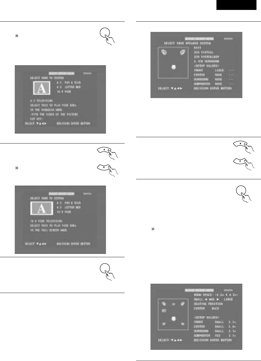
DEUTSCH
143
4Drücken Sie die ENTER-Taste, um das
Einstellungsmenü anzeigen zu lassen.
Im Einstellungsmenü wird die
ausgewählte Funktion in Gelb
angezeigt und die Werte der anderen
Funktionen erscheinen in Grün.
ENTER
Fernbedienung
[1] Einstellung der Fernsehschirmgröße
•Der gegenwärtig eingestellte Wert wird in Gelb angezeigt.
5Wählen Sie mit den •und ªCursor-
Tasten die gewünschte
Fernsehschirmgröße und die Anzeigeart
aus.
Die ausgewählte Fernsehbildschirm-
Größe wird in Gelb angezeigt und die
Beschreibung in Grün. Fernbedienung
6Drücken Sie zur Eingabe der
ausgewählten Einstellung die ENTER-
Taste.
•Der nachfolgend dargestellte
Bildschirm erscheint
ENTER
Fernbedienung
6[2] Lautsprecher-Einstellungen
•“Return” wird in Gelb angezeigt.
•Der derzeit eingestellte Wert wird in Grün angezeigt.
•Falls Sie die Einstellung nicht ändern möchten, drücken Sie
bei “Return” die ENTER-Taste. Es erscheint wieder der
Bildschirm wie in Schritt 2.
•Um die Einstellung zu ändern, fahren Sie mit dem
nachfolgend beschriebenen Schritt 7 fort.
7Wählen Sie mit den •und ªCursor-
Tasten das verwendete
Lautsprechersystem.
Fernbedienung
8Drücken Sie zur Eingabe der
ausgewählten Einstellung die ENTER-
Taste.
•Für andere als die “5.1-channel
surround”-Einstellungen erscheint
wieder der Setup-Bildschirm wie in
Schritt 2.
/Der Setup-Modus wird in Schritt 12
beendet.
Sie können den Setup-Modus auch
beenden, indem Sie auf dem Setup-
Bildschirm mit den • und ª Cursor-
Tasten “EXIT SETUP” auswählen
und anschließend die ENTER-Taste
drücken.
•Falls “5.1-channel surround”
ausgewählt wurde, erscheint der
nachfolgend dargestellte Bildschirm.
ENTER
Fernbedienung
[3] Raum- und Sitzposition-Einstellungen
•Der gegenwärtig eingestellte Wert wird in Grün angezeigt.

DEUTSCH
144
9Wählen Sie mit den •und ª
Cursor-Tasten “SEATING
POSITION”, und geben Sie dann
mit den 0und 1Cursor-Tasten
die Raumgröße ein.
•Die eingegebene Größe wird
in Gelb angezeigt. Fernbedienung
10 Wählen Sie mit den •und ª
Cursor-Tasten “SEATING
POSITION”, und geben Sie dann
mit den 0und 1Cursor-Tasten
die Position ein.
•Die eingegebene Position
wird in Gelb angezeigt. Fernbedienung
11 Drücken Sie zum Beenden der
Einstellungen die ENTER-Taste.
•Es erscheint wieder der Bildschirm
wie in Schritt 2.
ENTER
Fernbedienung
12 Drücken Sie zum Beenden des Setup-
Modus die SETUP-Taste.
Sie können den Setup-Modus auch
beenden, indem Sie auf dem Setup-
Bildschirm mit den •und ªCursor-
Tasten “EXIT SETUP” auswählen
und anschließend die ENTER-Taste
drücken.
SETUP
Fernbedienung
Wissenswertes über die Lautsprechersystem-
Einstellungen
B2CH VIRTUAL
Wählen Sie diese Einstellung, wenn Sie das Gerät nur mit den
beiden Lautsprechern für die vorderen Kanäle verwenden.
B2CH VIRTUAL & SW
Wählen Sie diese Einstellung, wenn Sie zwei Lautsprecher für
die vorderen Kanäle und einen Subwoofer mit integriertem
Verstärker verwenden.
•Einstellungen
Frontlautsprecher : Klein
Subwoofer : Ja
Subwoofer-Frequenz : 150 Hz
Stellen Sie die Frontlautsprecher und den Subwoofer im
gleichen Abstand auf.
B5.1CH SURROUND
Wählen Sie diese Einstellung, wenn Sie zwei Lautsprecher für
die vorderen Kanäle, einen Center-Lautsprecher, zwei
Lautsprecher für die Surround-Kanäle und einen Subwoofer mit
integriertem Verstärker verwenden.
•Einstellungen
Frontlautsprecher : Klein 2.7m (9ft)
Center-Lautsprecher : Klein 2.4m (8ft)
Surround-Lautsprecher: Klein 2.1m (7ft)
Subwoofer : Ja 2.7m (9ft)
Subwoofer-Frequenz : 150 Hz
Die Raumgröße ist auf “MED” eingestellt und die
Zuhörposition auf “BACK”.
HINWEIS:
•Das Lautsprechersystem wurde werkseitig auf “2CH VIRTUAL”
eingestellt. Falls Sie Lautsprecher für die beiden vorderen Kanäle
und einen Subwoofer verwenden, ändern Sie diese Einstellung
auf “2CH VIRTUAL & SW”.

DEUTSCH
145
(3) Detailliertes System-Setup (Änderung der Systemeinstellungen)
•Die Einstellungen aus dem Quick System-Setup und die werkseitigen Original-Einstellungen werden im Systemeinstellungs-Änderungsmenü
geändert. Die Einstellungen bleiben bis zur nächsten Änderung im Speicher gespeichert, auch wenn zwischenzeitlich die Stromversorgung
ausgeschaltet wird.
[1] Lautsprecher-Einstellungen (Lautsprechertyp und ob der Lautsprecher angeschlossen ist)
•Die Ausgangskomponente der verschiedenen Kanäle und deren Eigenschaften werden je nach verwendeter Lautsprecher-Kombination
automatisch eingestellt.
1Drücken Sie die SETUP-Taste, um sich
den Setup-Bildschirm anzeigen zu
lassen.
SETUP
Fernbedienung
2Wählen Sie mit den •und ªCursor-Tasten “SYSTEM
SETUP” unter “<ADVANCED SETUP>”, und drücken Sie
dann die ENTER-Taste.
ENTER
Fernbedienung Fernbedienung
3Wählen Sie im Systemeinstellungs-Änderungsmenü mit den
0und 1Cursor-Tasten das “SPEAKER CONFIGURATION”-
Tag-Symbol, und drücken Sie dann die ENTER-Taste.
3
Wenn sich der Cursor an einem Tag-Symbol im
Systemeinstellungs-Änderungsmenü befindet, kann der
Einstellungsbildschirm auch durch Drücken der ªCursor-
Taste ausgewählt werden. Durch Drücken der •Cursor-
Taste können Sie zum Tag-Symbol zurückkehren.
•Es erscheint der in Schritt 4 dargestellte Lautsprecher-
Einstellungsbildschirm.
ENTER
Fernbedienung Fernbedienung
4Wählen Sie mit den •, ª, 0und 1Cursor-Tasten, ob die
verschiedenen Lautsprecher angeschlossen sind, und zudem
ihre Größe und weitere Parameter.
Fernbedienung
•Die gerade eingestellte Funktion wird in Gelb und die
Einstellwerte für die anderen Funktionen werden in Grün
angezeigt.
CENTER-LAUTSPRECHER
FRONTLAUTSPRECHER
SUBWOOFER
SURROUND
LAUTSPRECHER
5Drücken Sie zur Eingabe der
Einstellungen die ENTER-Taste.
•Der nächste Bildschirm im
Systemeinstellungs-Änderungsmenü
erscheint.
ENTER
Fernbedienung

DEUTSCH
146
HINWEIS:
•Wählen Sie die Lautsprechergröße nicht nach den Lautsprecher-
Abmessungen, sondern nach der Kapazität zur Wiedergabe von
Niederfrequenzen (mehr als 100 Hz oder weniger) aus. Wenn Sie
keine Kenntnis über die Kapazität haben, bestimmen Sie die
Einstellung, indem Sie den Klang in den beiden Einstellungen
“Small” und “Large” vergleichen. Dabei sollte die Lautstärke
niedrig genug eingestellt sein, so dass die Lautsprecher nicht
beschädigt werden.
HINWEIS:
•Wählen Sie “Groß” oder “Klein” aus - gemeint ist nicht die
tatsächliche Größe des Lautsprechers, sondern die Kapazität bei
der Wiedergabe von Niederfrequenzsignalen (ca. 100 Hz und
darunter). Wenn Sie darüber nicht Bescheid wissen, versuchen
Sie, den Sound in beiden Einstellungen zu vergleichen (die
Lautstärke auf einen Pegel einstellen, der niedrig genug ist, so
dass die Lautsprecher nicht beschädigt werden), um die korrekte
Einstellung zu bestimmen.
Parameter
Groß…… Wählen Sie diese Einstellung, wenn Lautsprecher
verwendet werden, die leise Töne von unter 100 Hz
vollständig reproduzieren können.
Klein…… Wählen Sie diese Einstellung, wenn Lautsprecher
verwendet werden, die nicht ausreichend Lautstärke
erzeugen, wenn Niederfrequenzen von 100 Hz und
weniger wiedergegeben werden. Wenn diese
Einstellung gewählt wird, werden Frequenzen, die
unterhalb der in der Subwoofer-Frequenzeinstellung
eingestellten Frequenz liegen, dem Subwoofer zugeteilt.
Keine…... Wählen Sie diese Einstellung, wenn keine Lautsprecher
installiert sind.
Ja/Nein…Wählen Sie “Ja”, wenn ein Subwoofer installiert ist;
wählen Sie “Nein”, wenn kein Subwoofer installiert ist.
IWenn der Subwoofer ausreichende Niederfrequenz-
Wiedergabekapazität bietet, kann guter Sound erzielt werden,
auch wenn “Klein” bei den Front-, Center- und Surround-
Lautsprechern eingestellt ist.
Bei den meisten Lautsprechersystem-Konfigurationen wird die
KLEIN-Einstellung für alle fünf Hauptlautsprecher und
Subwoofer verwendet, wobei mit einem angeschlossenen
Subwoofer die besten Ergebnisse erzielt werden.
Subwoofer-Frequenz (SW FREQ.)
•Stellen Sie bei der Subwoofer-Frequenz im
Lautsprechereinstellungs-Bildschirm die Bass-
Überschneidungsfrequenz für den Subwoofer-Ausgang ein.
•Wählen Sie “80 Hz”, “120 Hz”, “150 Hz” oder “180 Hz” (–6 dB
für jeden). Bass-Sound unterhalb dieser Frequenzen wird vom
Subwoofer ausgegeben.
(Werkseitig ist “150 Hz” eingestellt.)
Zuteilung der Niederfrequenzen
•Im Dolby Digital-, Dolby Pro Logic II-, DTS-, und dem virtuellen
Surround-Modus werden die Niederfrequenzsignale für Kanäle,
deren Lautsprechereinstellungen auf “Klein” gestellt sind, dem
Subwoofer zugeteilt. Die Niederfrequenzen der Kanäle mit der
Einstellung “Groß” werden von diesen Kanälen wiedergegeben.
(Bei einer Einstellung von “120 Hz” geben die Kanäle mit einer
“Klein”-Einstellung Sound von 120 Hz und mehr wieder,
während Bass-Frequenzen unter 120 Hz vom Subwoofer
ausgegeben werden.)
•In den Surround-Modi, die oben nicht aufgelistet sind, werden
Niederfrequenzen, die unterhalb der in der Subwoofer-
Frequenzeinstellung eingestellten Frequenz liegen, vom
Subwoofer ausgegeben - dabei ist es egal, ob die Lautsprecher
auf “Groß” oder “Klein” eingestellt sind.
•Stellen Sie die Subwoofer-Frequenz entsprechend der
Niederfrequenz-Wiedergabefähigkeit Ihrer Lautsprecher und
Ihres Subwoofers ein.
Subwoofer-Modus (SW MODE)
•Die Subwoofer-Moduseinstellung ist nur gültig, wenn “LARGE”
für die Front-Lautsprecher und “YES” für den Subwoofer in den
“SPEAKER CONFIGURATION”-Einstellungen eingestellt ist.
•Wenn der “LFE+MAIN”-Wiedergabemodus angewählt ist,
werden die Niederfrequenzsignale der auf “LARGE”
eingestellten Kanäle gleichzeitig von diesen Kanälen und dem
Subwoofer-Kanal produziert.
Bei diesem Wiedergabemodus dehnen sich die
Niederfrequenzsignale gleichmäßiger über den Raum aus.
Abhängig von der Größe und dem Schnitt des Raumes können
jedoch Interferenzen auftreten, die eine Reduzierung der
tatsächlichen Lautstärke der Niederfrequenzsignale zur Folge
haben kann.
•Wenn der “LFE”-Wiedergabemodus angewählt ist, werden die
Niederfrequenzsignale des mit “LARGE” angewählten Kanals
nur von dem Kanal wiedergegeben. Daher handelt es sich bei
den vom Subwoofer-Kanal wiedergegeben
Niederfrequenzsignalen, nur um den Niederfrequenz-
Signalbereich von LFE (nur während der Dolby Digital- oder DTS-
Signalwiedergabe) und der im Einrichtungsmenü als “SMALL”
spezifizierten Kanäle.
•Wählen Sie den Wiedergabemodus, der eine Basswiedergab mit
Herz ermöglicht.
•Wenn der Subwoofer auf “YES” gestellt ist, wird Bass,
ungeachtet der Subwoofer-Moduseinstellung in einem anderen
Surround-Modus als dem Dolby/DTS, vom Subwoofer
ausgegeben.

DEUTSCH
147
[2] Verzögerungszeit (Abstandseinstellung)
•Geben Sie die Abstände zwischen der Hörposition und den Lautsprechern ein und bestimmen Sie die Surround-Verzögerungszeit.
•Werkseitig wurde die Verzögerungszeit auf die im nachfolgenden Schritt 3 angegebenen Standardwerte eingestellt.
Vorbereitende Schritte:
Messen Sie die Abstände zwischen der Hörposition und den Lautsprechern.
FRFL
SRSL
Center
L1: Abstand zwischen dem
Centerlautsprecher und der
Hörposition
L2: Abstand zwischen dem
Centerlautsprecher und der
Hörposition
L3: Abstand zwischen dem Surround-
Lautsprecher und der Hörposition
Hörposition
1
2
Lesen Sie sich die auf Seite 145 beschriebenen Schritte 1 und
2 durch, wenn das Systemeinstellungs-Änderungsmenü
derzeit nicht angezeigt wird.
Wählen Sie im Systemeinstellungs-Änderungsmenü mit den
0und 1Cursor-Tasten “DELAY TIME”, und drücken Sie
dann die ENTER-Taste.
•Es erscheint der Verzögerungszeit-Einstellungsbildschirm.
ENTER
Fernbedienung Fernbedienung
3Wählen Sie “Yes” als “Default”, um die Verzögerungszeiten
für die verschiedenen Lautsprecher auf die Standardwerte
einzustellen.
•Die Maßeinheit für den Abstand kann mit den 0und 1
Cursor-Tasten zwischen “m” (Meter) und “ft” (Fuß)
geändert werden. Falls Sie die Maßeinheit nicht ändern
möchten, drücken Sie die ªCursor-Taste, um mit dem
nächsten Schritt fortzufahren.
BYes: Die Standardwerte werden eingestellt.
BNo: Die gegenwärtigen Einstellungen werden
beibehalten.
4Wählen Sie mit den •und ªCursor-Tasten den Lautsprecher
aus und geben Sie dann mit den 0und 1Cursor-Tasten den
Abstand zwischen dem leweiligen Lautsprecher und der
Zuhörposition ein.
•Der Abstand ändert sich bei jedem Drücken der 0und 1
Cursor-Tasten um 0,1 Meter. Wählen Sie den Wert, der
dem gemessenen Abstand am nächsten kommt.
5Drücken Sie zur Eingabe der
Einstellungen die ENTER-Taste.
•Der nächste Bildschirm im
Systemeinstellungs-Änderungsmenü
erscheint.
ENTER
Stellen Sie sicher, dass die für die verschiedenen
Lautsprecher eingestellte Abstandsabweichung nicht
mehr als 3,0 Meter beträgt.
Wenn ein nicht anwendbarer Abstand eingestellt wurde,
wird “CAUTION: OUT OF SETTING RANGE” angezeigt.
Ändern Sie die Lautsprecherposition und nehmen Sie eine
neue Einstellung vor.
Fernbedienung
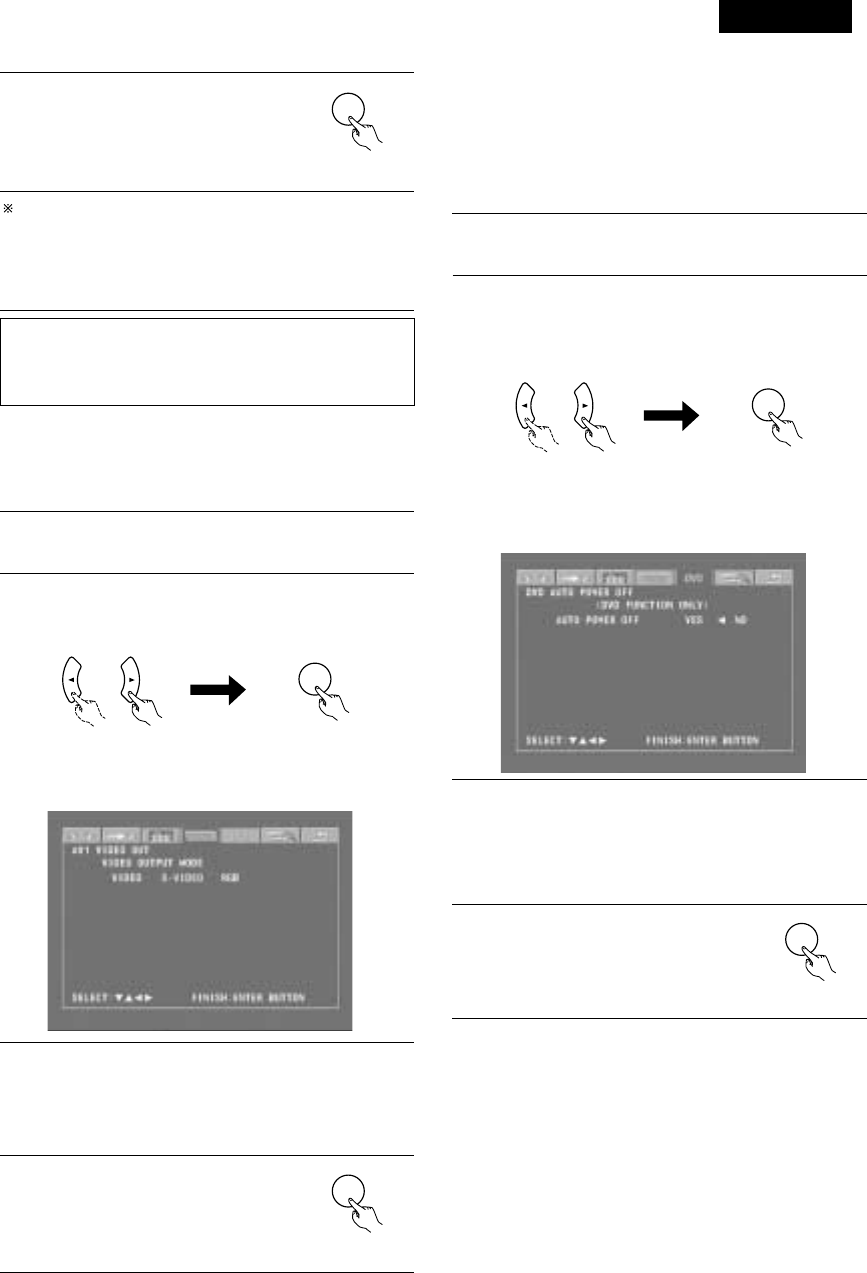
DEUTSCH
HINWEIS:
Wenn die Kanalpegel in den Kanalpegel-Einstellungen eingestellt
worden sind, werden die eingestellten Werte in allen
Wiedergabemodi angewendet.
Der “Kanalpegel”-Bildschirm wird wieder angezeigt.
Um die Einstellung nach der Justierung zu verlassen Lassen Sie
den Kanalpegel-Einstellbildschirm anzeigen, wählen Sie
anschließend mit den Cursor-Tasten •, ª, 0und 1“LEVEL
CLEAR” und “YES”. Die Pegeleinstellung aller Lautsprecher lautet
0 dB.
149
7Drücken Sie zur Eingabe der
Einstellungen die ENTER-Taste.
•Der nächste Bildschirm im
Systemeinstellungs-Änderungsmenü
erscheint.
ENTER
Fernbedienung
[5] DVD-Einstellung der automatischen DVD-Strom-
Ausschaltfunktion
•Der ADV-M71 ist mit einer Funktion ausgestattet, mit deren Hilfe
das Gerät automatisch in den Standby-Modus geschaltet wird,
wenn bei aktivierter DVD-Funktion 30 Minuten lang keine
Bedienung erfolgt. Geben Sie hier ein, ob diese Funktion ein- oder
ausgeschaltet werden soll.
•Die Werkseinstellung lautet auf “No”.
1Lesen Sie sich die auf Seite 33 beschriebenen Schritte 1 und
2 durch, wenn das Systemeinstellungs-Änderungsmenü
derzeit nicht angezeigt wird.
2Wählen Sie im Systemeinstellungs-Änderungsmenü mit den
0-und 1-Cursor-Tasten “DVD AUTO POWER OFF”, und
drücken Sie dann die ENTER-Taste.
•Der Bildschirm zur Einstellung der automatischen DVD-
Strom-Ausschaltung erscheint.
ENTER
Fernbedienung Fernbedienung
ENTER
Fernbedienung Fernbedienung
3Wählen Sie mit den 0- und 1-Cursor-Tasten den “Auto
Power Off”-Modus.
BYes: Die automatische Strom-Ausschaltfunktion ist bei
eingestellter DVD-Funktion aktiviert.
BNo: Die automatische Strom-Ausschaltfunktion ist
deaktiviert.
[4] Einstellung des AV1-Videoausgangs
•Für die Auswahl, ob Videomischsignale oder S-Videosignale oder
RGB-Signale von den AV1 SCART-Anschlüssen ausgegeben
werden sollen.
•Die Werkseinstellung lautet auf “VIDEO”.
1
2
Lesen Sie sich die auf Seite 145 beschriebenen Schritte 1 und
2 durch, wenn das Systemeinstellungs-Änderungsmenü
derzeit nicht angezeigt wird.
Wählen Sie im “SYSTEM SETUP MENU”-Bildschirm “AV1
VIDEO OUTPUT” und drücken Sie die ENTER-Taste.
•Wechseln Sie zum “AV1 VIDEO OUT”-Bildschirm.
3
4
Wählen Sie “VIDEO OUTPUT”.
•VIDEO: Zusammengesetzte Videosignale werden
ausgegeben.
•S-VIDEO: S-Videosignale werden ausgegeben. Wählen
Sie “DVD RGB OUTPUT”.
•RGB: Es werden RGB-Signale ausgegeben.
Drücken Sie zur Eingabe der
Einstellungen die ENTER-Taste.
•Der nächste Bildschirm im
Systemeinstellungs-Änderungsmenü
erscheint.
ENTER
Fernbedienung
4Drücken Sie zur Eingabe der
Einstellungen die ENTER-Taste.
•Der nächste Bildschirm im
Systemeinstellungs-Änderungsmenü
erscheint
ENTER
Fernbedienung

DEUTSCH
150
4Drücken Sie zur Eingabe der
Einstellungen die ENTER-Taste.
•Der nächste Bildschirm im
Systemeinstellungs-Änderungsmenü
erscheint.
ENTER
Fernbedienung
Eingangsfunktions-Einstellungen
•LINE-1 und LINE-2 können wie nachfolgend beschrieben
eingestellt werden.
LINE-1 : Hier können Sie zwischen “MD”, “CD-R”, “MD/CD-R”
oder “AUX” auswählen.
(“MD/CD-R” kann nur ausgewählt werden, wenn
sowohl ein MD-Recorder, ein Kassettendeck als auch
ein CD-Recorder angeschlossen ist und die
Systemfunktionen angewendet werden.)
LINE-2 : Hier können Sie zwischen “TAPE”, “MD”, “AUX” oder
“D.AUX” auswählen. (Wählen Sie die Einstellung
“D.AUX”, um den Digitaleingang D.AUX zusammen
mit dem Analogeingang LINE-2 zu verwenden.)
•Die Einstellung für LINE-1 hat Priorität. Wenn einmal eine
Funktion für LINE-1 eingestellt wurde, kann dieselbe Funktion
nicht für LINE-2 eingestellt werden. (Wenn z. B. “MD” für LINE-
1 ausgewählt wurde, steht “MD” für LINE-2 nicht mehr zur
Verfügung.)
LINE-1/LINE-2 Einstellung des analogen Aufnahmeausgangs
•Wählen Sie normalerweise die Einstellung “On”.
•Wählen Sie die Einstellung “Off”, wenn die DVD-Funktion oder
die exklusive Digitaleingangs-Funktion D.AUX eingestellt ist,
sofern bei der Wiedergabe von Tonquellen mit hohen Bitraten im
Dolby Virtual Speaker-Modus Störungen auftreten.
•Diese Einstellung wird ausschließlich im Dolby Virtual Speaker-
Modus für die DVD-Funktion oder die exklusive Digitaleingangs-
Funktion D.AUX angewendet. (In anderen Surround-Modi mit
anderen Eingangsfunktionen werden – unabhängig von dieser
Einstellung – analoge Aufnahmesignale ausgegeben.)
•Die analoge Aufnahme ist nicht möglich, wenn die Einstellung
“Off” ausgewählt wurde. Wählen Sie für die Aufnahme einen
anderen Modus als den Dolby Virtual Speaker-Modus (zum
Beispiel Stereo).
(4) Nach der Änderung der Systemeinstellungen
•Hiermit ist die Änderung der Systemeinstellungen abgeschlossen.
Wenn die Lautsprecher-Einstellungen, die Verzögerungszeiten und
die Kanalpegel einmal eingestellt worden sind, müssen diese
Einstellungen nicht mehr geändert werden, bis die
angeschlossenen AV-Komponenten oder Lautsprecher
ausgetauscht werden oder der Aufstellungsort der Lautsprecher
verändert wird.
•Automatische DVD-Strom-Ausschaltung und
Funktionseinstellungen nach Bedarf
1Drücken Sie im Systemeinstellungs-
Änderungsmenü die SETUP-Taste.
•Die neuen Einstellungen wurden
eingegeben und die
Bildschirmanzeige schaltet sich aus.
SETUP
Fernbedienung
Das Setup-Verfahren kann durch Drücken dieser Taste jederzeit
beendet werden.
HINWEIS:
•Wenn die Systemeinstellungen im Systemeinstellungs-
Änderungsmenü geändert worden sind und im Quick System-
Setup ein Lautsprecher ausgewählt wurde, werden die
Lautsprecher- und Verzögerungszeit-Einstellungen auf die für den
Quick System-Setup vorprogrammierten Werte geändert.
3Wählen Sie mit den •- und ª-Cursor-Tasten den
einzustellenden Punkt und führen Sie die Einstellungen dann
mit den 0- und 1-Cursor-Tasten aus.
BLINE-1 Auswahl der Funktionsbezeichnung (Die
Werkseinstellung lautet auf "MD”.)
MD
CD-R
AUX MD/CD-R
BLINE-2 Auswahl der Funktionsbezeichnung (Die
Werkseinstellung lautet auf “TAPE”.)
TAPE D.AUXAUX
BLINE-1/LINE-2 REC OUT
: Geben Sie ein, ob der Aufnahmeausgang während der
Wiedergabe im Dolby Virtual Speaker-Modus ein- oder
ausgeschaltet werden soll, wenn die DVD-Funktion oder
die exklusive Digitaleingangs-Funktion D.AUX eingestellt
ist.
On : Die Signale werden in Stereo ausgegeben.
(Werkseinstellung)
Off : Die Signale werden nicht ausgegeben. (Es ist keine
Aufnahme möglich.)
[6] Funktionseinstellungen
•Geben Sie die LINE-1- und LINE-2 Funktionsbezeichnungen ein und
schalten Sie den analogen Aufnahmeausgang (REC OUT) ein oder
aus.
•Nehmen Sie die Einstellungen bei gleichzeitiger Verwendung eines
Gerätes der D-M31-Serie entsprechend der verwendeten
Komponenten vor und führen Sie die Systemanschlüsse für die
praktischen Systemfunktionen aus.
•Der D.AUX-Digitaleingang kann LINE-2 zugeordnet werden.
1Lesen Sie sich die auf Seite 145 beschriebenen Schritte 1 und
2 durch, wenn das Systemeinstellungs-Änderungsmenü
derzeit nicht angezeigt wird.
2Wählen Sie im Menü mit den 0- und 1-Cursor-Tasten
“FUNCTION ASSIGNMENT” aus, und drücken Sie dann die
ENTER-Taste.
•Der Eingangsfunktions-Einstellungsbildschirm erscheint.
ENTER
Fernbedienung Fernbedienung

DEUTSCH
151
B
BAND
PHONES
VOLUME
ON / STANDBY
DVD SURROUND RECEIVER ADV-M71
TONE/SDB
FUNCTION
MENU/SET +
-
SURROUND/SELECT
PUSH
-
PARAM.
2
+
-
+
-
RC-966
A / V
3
A-B REPEAT
SEARCH MODE
ONOFF
REPEAT RANDOM
CLEAR ZOOMSLIDE MODE
PROG/ DIRECT
MEMO BANDMODE
STAT US
RETURN
ANGLE AUDIO
SUB TITLE
SETUP TONE /SDB
FUNCTIONSURROUNDINPUT MODETEST TONE
DVD
TUNER
CH
3
-
+
21
654
987
0/10
CALL
ENTER
MUTING
+10
DISPLAY MENU
TOP MENU
SYSTEM MD
CDR TAPE
TUNER TV / VCR
SURROUND
PARAMETER
CH SELECT
VCR
NTSC/PAL
SLEEP
ENTER EDIT/MENUCHARAC.
REC
TIMETITLE
TUNING /
TV VOL
TV CH TV CH
TUNERDVD
MD/ LINE-1 TAPE/ LINE-2
AUTO DECODE
VIRTUALDIRECT
5CH STEREO
STEREO
D.AUX
-
+
VCR CH
IN/SURR.
IN/SURR.
DVD
T VTV INSOURCE
9
8
21
76
+
-
CD SRS
RTCT
PTYRDS
2
(1) Vor dem Betrieb
11 WIEDERGABE
1Siehe “ANSCHLÜSSE” (Seite 120 bis 126) und prüfen Sie, ob
alle Anschlüsse korrekt sind.
2Schalten Sie die
Stromversorgung
ein.
Betätigen Sie den
POWER-Schalter
(Taste).
Bei Betätigung wird die Stromversorgung eingeschaltet und
das Display erleuchtet. Der Sound wird für einige Sekunden
ausgeblendet, danach arbeitet das Gerät normal. Bei
nochmaliger Betätigung wird die Stromversorgung
ausgeschaltet, der Bereitschaftsmodus wird aktiviert und das
Display wird ebenfalls ausgeschaltet.
Bei jeder Betätigung der ON/STANDBY-Taste im
STANDBYStatus ist das Gerät immer noch an
Wechselspannung angeschlossen. Vergewissern Sie sich
bitte, dass das Netzkabel herausgezogen ist, wenn Sie das
Haus verlassen und beispielsweise in den Urlaub fahren.
ON / STANDBY
ON
Leuchtet
(grün)
Haupteinheit Fernbedienung

DEUTSCH
152
2
Legen Sie die Discs in das Disc-Fach mit der Schriftseite nach oben
weisend ein.
8 cm
Disc-Führung
Disc-Fach
HINWEIS:
•Bewegen Sie dieses Gerät nicht, wenn eine Disc abgespielt
wird. Anderenfalls kann die Disc zerkratzt werden.
(1) Disc-Fach öffnen und schließen
qSchalten Sie die Stromversorgung ein.
wDrücken Sie die OPEN/CLOSE-Taste.
Disc-Fach
OPEN/CLOSE-Taste
HINWEISE:
•Auch wenn die Stromversorgung in den Bereitschaftsmodus
geschaltet ist, wird die Stromversorgung des ADV-M71 nach
Drücken der OPEN/CLOSE-Taste eingeschaltet und das Disc-
Fach aktiviert. (Autom. Strom-Einschaltfunktion)
•Auch wenn eine andere Funktion als DVD eingestellt ist,wechselt
die Funktion nach Drücken der OPEN/CLOSE-Tastezu DVD und
das Disc-Fach wird aktiviert.
(Autom.Funktionswahl-Betrieb)
•Berühren Sie die Taste nicht mit einem Stift, usw.
12 cm Disc-Führung
(2) Discs einlegen
•Nehmen Sie die Disc vorsichtig aus der Hülle, berühren Sie dabei
nicht die Signaloberfläche und halten Sie sie mit der Schriftseite
nach oben weisend in der Hand.
•Legen Sie die Disc bei vollständig geöffnetem Disc-Fach in das
Fach.
•Legen Sie 12 cm-Discs in die äußere Fach-Führung (Abbildung 1), 8
cm-Discs in die innere Fach-Führung (Abbildung 2).
•Drücken Sie die OPEN/CLOSE-Taste. Die Disc wird automatisch
geladen.
•Das Disc-Fach wird auch durch Drücken der PLAY-Taste
automatisch geschlossen, um die Disc zu laden.
Abbildung 2
Inneres Disc-Fach
8 cm-Disc
HINWEISE:
•Wenn ein Fremdkörper beim Schließen in das Disc-Fach
gelangt, drücken Sie einfach erneut auf die
OPEN/CLOSETaste, damit sich das Fach wieder öffnet.
•Drücken Sie das Disc-Fach nicht mit der Hand zurück, wenn
die Stromversorgung ausgeschaltet ist.
Anderenfalls wird das Fach beschädigt.
•Legen Sie keine Fremdkörper in das Disc-Fach hinein.
Anderenfalls wird das Fach beschädigt.
(2) Disc einlegen
Abbildung 1
Äußeres Disc-Fach
12 cm-Disc

DEUTSCH
153
WICHTIGE SETUP-INFORMATIONEN
Dieses Gerät besitzt folgende Voreinstellungen:
“DISC SETUP”, “OSD SETUP”, “VIDEO SETUP”, “AUDIO SETUP”,
“RATINGS” und “OTHER SETUP”.
Diese Einstellungen wurden werkseitig ausgeführt. Wenn Sie sie auf
Ihre Bedürfnisse zuschneiden wollen, lesen Sie bitte Seite 206 bis
218.
1
2
3
ON
ON / STANDBY
Schalten Sie die Stromversorgung ein.
•Drücken Sie die Power-Taste; die Stromanzeige leuchtet
und die Stromversorgung wird eingeschaltet.
Drücken Sie die OPEN/CLOSE-Taste, um das Disc-Fach zu
öffnen.
Legen Sie die Disc in das Disc-Fach ein.
4Drücken Sie die OPEN/CLOSE-Taste.
5Drücken Sie die PLAY-Taste.
•Bei vielen interaktiven DVDs und Video-CDs mit
Wiedergabesteuerung erscheint ein Menü-Bildschirm.
Führen Sie in diesem Fall das Verfahren unter Punkt 6 aus,
um den gewünschten Punkt auszuwählen.
Interaktive DVDs beinhalten mehrere Winkel, Stories, usw.
DVD
1
Haupteinheit
Haupteinheit
Haupteinheit
Haupteinheit
Fernbedienung
Fernbedienung
B
BAND
PHONES
VOLUME
ON / STANDBY
DVD SURROUND RECEIVER ADV-M71
TONE/SDB
FUNCTION
MENU/SET +
-
SURROUND/SELECT
PUSH
-
PARAM.
(3)-1 (3)-8
(3)-3 (3)-2,(3)-4
(3)-5
(4)-1
+
-
+
-
A / V
3
A-B REPEAT
SEARCH MODE
ONOFF
REPEAT RANDOM
CLEAR ZOOMSLIDE MODE
PROG/ DIRECT
MEMO BANDMODE
STAT US
SETUP TONE /SDB
FUNCTIONSURROUNDINPUT MODETEST TONE
DVD
TUNER
CH
3
-
+
21
654
987
0/10
CALL
ENTER
MUTING
+10
SYSTEM MD
CDR TAPE
TUNER TV / VCR
SURROUND
PARAMETER
CH SELECT
VCR
NTSC/PAL
SLEEP
ENTER EDIT/MENUCHARAC.
REC
TIMETITLE
TUNING /
TV VOL
TV CH TV CH
TUNERDVD
MD/ LINE-1 TAPE/ LINE-2
AUTO DECODE
VIRTUALDIRECT
5CH STEREO
STEREO
D.AUX
-
+
VCR CH
IN/SURR.
IN/SURR.
DVD
T VTV INSOURCE
9
8
21
76
+
-
CD SRS
RTCT
PTYRDS
(3)-1
(3)-6
(3)-7
(3)-8
(3)-5 (4)-1
Beispiel: Bei DVDs mit
Menü-Bildschirmen
Beispiel: Bei Video-CDs mit
Wiedergabesteuerung
1. Opening
Banana
Strawberry
Pineapple
TOP MENU
Orange
Peach
Apple 2. 1st movement
3. 2nd movement
4. 3rd movement
5. Ending
(3) Wiedergabe
Leuchtet
(grün)

DEUTSCH
154
6Wählen Sie mit den Cursor-Tasten (•, ª, 0und 1) den
gewünschten Punkt aus.
•Bei einigen Disc ist ein zweiter Menü-Bildschirm
vorhanden. Wenn dies der Fall ist, drücken Sie die 9-
Taste, um den nächsten Menü-
Bildschirm anzeigen zu lassen.
(Siehe Disc-Hülle.)
Die Cursor-Taste (•, ª, 0und
1) können bei Video-CDs nicht
verwendet werden. Wählen Sie
mit den Nummerntasten den
gewünschten Punkt aus. Fernbedienung
7Drücken Sie die ENTER-Taste.
•Der gewünschte Punkt wird ausgewählt und die
Wiedergabe startet.
•Die können zum Menü-Bildschirm zurückkehren, indem die
TOP MENU-Taste während der
DVDWiedergabe gedrückt wird; dies hängt
jedoch von der Disc ab.
•Drücken Sie während der Wiedergabe einer
Video-Disc die RETURN-Taste, um zum
Menü-Bildschirm zurückzukehren.
Fernbedienung
Beispiel: Wenn “Apfel”
ausgewählt wird
Apple
ENTER
Banana
Strawberry
Pineapple
TOP MENU
Orange
Peach
Apple
8Stellen Sie die Lautstärke entweder mit dem Lautstärke-
Regler an der Haupteinheit oder mit den Lautstärke-
Bedienungstasten auf der Fernbedienung ein.
M.VOLUME -20
Die Lautstärke wird
auf der Anzeige
angezeigt.
+
-
VOLUME
Haupteinheit Fernbedienung
Lesen Sie hinsichtlich der Einzelheiten über die Surround-
Modi und Surround-Parameter den Abschnitt “12
Surround-Funktionen” auf den Seiten 156 bis 158.
•Im “AUTO”-Eingangsmodus werden die Signale der
wiedergegebenen Disc identifiziert, und die Dolby Digital-,
DTS- oder PCM-Entschlüsselung wird automatisch
ausgewählt und die Disc wird wiedergegeben.
•Im Dolby Virtual Speaker-Surround-Modus werden die
Signale der wiedergegebenen Disc automatisch in Dolby
Digital oder DTS entschlüsselt und dann im Dolby Virtual
Speaker-Surround-Modus wiedergegeben.
•Wenn im “AUTO DECODE”-Surround-Modus ein 5,1-
Kanal-Lautsprecher eingestellt wurde, werden die Signale
der wiedergegebenen Disc automatisch in Dolby Digital,
DTS oder Auto Stereo entschlüsselt, und die Disc wird
wiedergegeben.
•Wenn während der Tastenbedienung auf dem TV-
Bildschirm erscheint, ist dieser Betrieb mit dem ADV-M71 oder
mit dieser Disc nicht möglich.
Die Wiedergabefortsetzungs-Speicherfunktion kann nur
bei Disc aktiviert werden, bei denen die verstrichene Zeit
während der Wiedergabe auf dem Display angezeigt wird.
1
2
BAND
Drücken Sie während der Wiedergabe die STOP-Taste auf der
Haupteinheit oder der Fernbedienung, um die Wiedergabe zu
stoppen und das Hintergrundbild anzeigen zu lassen.
<Wiedergabefortsetzungs-Speicherfunktion (nur DVD)>
•Wenn beim ADV-M71 die STOP-Taste gedrückt wird, wird
diese Position im Speicher gespeichert. Zu diesem Zeitpunkt
blinkt “1” auf dem Display. Wenn nach Drücken der STOP-
Taste die PLAY-Taste gedrückt wird, wird die Wiedergabe an
der Position fortgesetzt, an der zuvor die Wiedergabe gestoppt
wurde. Die Wiedergabefortsetzungs-Speicherfunktion wird
aufgehoben, sobald das Disc-Fach geöffnet oder die STOP-
Taste ein zweites Mal gedrückt wird.
Autom. Strom-Ausschaltfunktion
•Der ADV-M71 ist mit einer Funktion ausgestattet, mit der
die Stromversorgung in Bereitschaft geschaltet wird,
wenn im Stopp-Modus und bei aktivierter DVD-Funktion
30 Minuten lang keine Bedienung erfolgt.
•Diese Funktion ist werkseitig ausgeschaltet. Wenn Sie
sie einschalten möchten, stellen Sie die “DVD autom.
Strom-Ausschalteinstellung” auf “YES”, wie auf Seite
149 beschrieben.
Haupteinheit Fernbedienung
(4) Wiedergabe stoppen
Über die DVD-Standby-Funktion
Wenn die Funktion des ADV-M71 auf DVD gestellt ist, wird
der DVD-Standby-Modus automatisch eingestellt, wenn die
Disc ungefähr 10 Minuten im Stopp-Modus verbleibt.
•Im DVD-Standby-Modus ist sowohl die Stromversorgung
des DVD-Bereiches als auch der Videosignal-Ausgang
ausgeschaltet.
Auf der Anzeige des ADV-M71 wird zu diesem Zeitpunkt
“DVD standby” angezeigt.
•Wenn der DVD-Standby-Modus aktiviert ist, bleibt die
Stromversorgung der anderen Bereiche eingeschaltet,
und die Funktionsumschaltung und andere Bedienungen
können am Hauptgerät oder auf der Fernbedienung
ausgeführt werden. Beim Drücken einer DVD-
Bedienungstaste (die Wiedergabe-/Pausetaste und die
Öffnen-/Schließen-Taste am Hauptgerät, die
Wiedergabetaste auf der Fernbedienung usw.) schaltet
sich die Stromversorgung des DVD-Bereiches
automatisch ein, und die Disc-Wiedergabe und das
Öffnen-/Schließen des Disc-Halters kann ausgeführt
werden.
HINWEIS:
•Die DVD-Standby-Funktion schaltet nur die Stromversorgung des
DVD-Bereiches aus. Diese Funktion unterscheidet sich von der
automatischen DVD-Strom-Ausschaltfunktion, die mit den
Systemeinstellungen im Setup ausgeführt worden sind und bei
der der DVD-Bereich funktionsfähig bleibt.
•Legen Sie die Disc in die Disc-Führung.
•Legen Sie nur eine Disc in das Disc-Fach.
•Die Disc dreht sich, während der Menü-Bildschirm auf dem TV-
Bildschirm angezeigt wird.
HINWEISE:
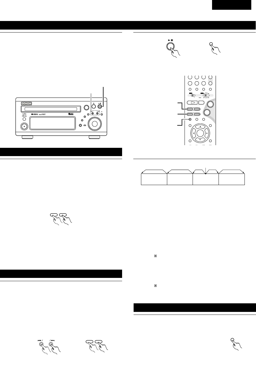
DEUTSCH
155
1Drücken Sie während der Wiedergabe die 13-Taste auf der
Haupteinheit oder die 3-Taste auf der Fernbedienung.
•Drücken Sie die PLAY-Taste, um die normale Wiedergabe
fortzusetzen.
3
Haupteinheit Fernbedienung
(5) Wiedergabe von Standbildern (Pause)
B
BAND
PHONES
VOLUME
ON / STANDBY
DVD SURROUND RECEIVER ADV-M71
TONE/SDB
FUNCTION
MENU/SET +
-
SURROUND/SELECT
PUSH
-
PARAM.
(7)-1
(5)-1
+
-
A / V
3
STAT US
SETUP TONE /SDB
FUNCTIONSURROUNDINPUT MODETEST TONE
DVD
CH
987
0/10
CALL
ENTER
MUTING
+10
SYSTEM MD
CDR TAPE
TUNER TV / VCR
SURROUND
PARAMETER
CH SELECT
VIRTUALDIRECT STEREO
-
+
VCR CH
IN/SURR.
IN/SURR.
DVD
9
8
21
76
+
-
(5)-1,(8)-1
(6)-1,(9)-1
(7)-1
HINWEIS:
•In einigen Fällen erscheint der Menü-Bildschirm wieder,
wenn eine der 6/ 7-Tasten während der Menü-
Wiedergabe einer Video-CD gedrückt wird.
1
76
Drücken Sie während der Wiedergabe eine der 6/ 7-
Tasten auf der Haupteinheit oder der Fernbedienung.
6:Rückwärtsrichtung
7:Vorwärtsrichtung
•Bei erneuter Betätigung wird die Suchgeschwindigkeit
erhöht (DVD, VIDEO CD in sieben Schritten, CD in vier
Schritten).
•Drücken Sie die PLAY-Taste, um die normale Wiedergabe
fortzusetzen.
Fernbedienung
1Drücken Sie während der Wiedergabe eine der Überspringen-
Tasten auf der Haupteinheit oder der Fernbedienung.
8/ : Rückwärtsrichtung (PREVIOUS)
9/ : Vorwärtsrichtung (NEXT)
•Die Anzahl von Kapiteln oder Titeln, die übersprungen wird,
entspricht der Anzahl der Tastenbetätigungen.
•Wenn die Überspringen-Taste rückwärts einmal gedrückt
wird, kehrt der Aufnahmekopf zurück zum Anfang des
gegenwärtig abgespielten Kapitels oder Titels.
(6) Suche vorwärts/rückwärts
(7)
Zum Anfang eines Kapitels oder Titels springen
+
-
9
8
Haupteinheit Fernbedienung
Wiedergabeposition
Kapitel/Titel Kapitel/Titel Kapitel/Titel Kapitel/Titel
Rückwärtsrichtung ,/Vorwärtsrichtung (Wiedergaberichtung)
HINWEIS:
•In einigen Fällen erscheint der Menü-Bildschirm wieder,
wenn eine der 8/ 9Tasten während der Menü-
Wiedergabe einer Video-CD gedrückt wird.
Suche mit Hilfe der Zifferntasten
qDrücken Sie während der Wiedergabe die Suchmodus-
Taste auf der Fernbedienung.
•Der Modus ändert sich bei jedem Drücken der Taste wie
nachfolgend gezeigt:
Für DVDs : Spur ,/Kapitel
Für CDs und Video-CDs: Spur (keine Umschaltung)
Der durch Drücken der Suchmodus-Taste eingestellte
Suchmodus bleibt bis zum Ausschalten der
Stromversorgung im Speicher gespeichert.
wGeben Sie die Titel-, Kapitel- oder Spurnummer, die Sie
wiedergeben lassen möchten, mit den Zifferntasten auf
der Fernbedienung ein.
Einige DVDs oder Video-CDs sind möglicherweise
anders konstruiert und funktionieren auf eine andere
als die hier beschriebene Weise..
1Drücken Sie während der Wiedergabe die 3-Taste auf der
Haupteinheit oder der Fernbedienung.
•Das Bild bewegt sich bei jeder
Tastenbetätigung einen Rahmen
vorwärts.
•Drücken Sie die PLAY-Taste, um die
normale Wiedergabe fortzusetzen.
(8)
Repetitionswiedergabe (nur bei DVDs und Video-CDs)
3
Fernbedienung

DEUTSCH
156
1Drücken Sie im Standbild-Modus eine der 6/ 7-Tasten
auf der Fernbedienung.
6:Rückwärtsrichtung
7:Vorwärtsrichtung
•Wenn diese Taste erneut gedrückt wird, nimmt die
Geschwindigkeit der langsamen Wiedergabe zu. (Vier
Schritte) (Drei Schritte bei Video-CDs)
•Drücken Sie die PLAY-Taste, um die normale Wiedergabe
fortzusetzen.
(9)
Wiedergabe in Zeitlupe
(nur bei DVDs und Video-CDs )
76
Fernbedienung
HINWEIS:
•Die Zeitlupen-Wiedergabe in Rückwärtsrichtung ist bei
Video-CDs nicht möglich.
B
BAND
PHONES
VOLUME
ON / STANDBY
DVD SURROUND RECEIVER ADV-M71
TONE/SDB
FUNCTION
MENU/SET +
-
SURROUND/SELECT
PUSH
-
PARAM.
5
13
+
-
-
A / V
3
STAT US
SETUP TONE /SDB
FUNCTIONSURROUNDINPUT MODETEST TONE
DVD
TUNER
CH
654
987
0/10
CALL
MUTING
+10
SYSTEM MD
CDR TAPE
TUNER TV / VCR
AUTO DECODE
VIRTUALDIRECT
5CH STEREO
STEREO
IN/SURR.
IN/SURR.
DVD
9
8
21
76
+
-
5
23
1
12
BETRIEB DER SURROUND-FUNKTIONEN
(1) Eingangsmodus-Einstellung
1Wählen Sie die Eingangsfunktion für die Wiedergabe durch
Drücken der FUNCTION-Taste.
FUNCTION
FUNCTION
•Die Funktion wird wie folgt gewechselt.
•Werkseinstellung (LINE 1) = MD, (LINE 2) = TAPE
DVD TUNER (LINE2) D.AUX
(LINE1)
Haupteinheit Fernbedienung
2Wenn als Eingangsfunktion DVD oder D.AUX ausgewählt
worden ist, wählen Sie den Eingangsmodus aus, indem Sie
die INPUT MODE-Taste auf dem Fernbedienungsgerät
drücken.
INPUT MODE
•“ANALOG” kann nicht ausgewählt werden, wenn als
Eingangsfunktion “DVD” ausgewählt worden ist.
•Die Option “ANALOG” kann ausgewählt werden, wenn
“LINE-2” in “FUNCTION ASSIGNMENT” unter “SYSTEM
SETUP” in den detaillierten Einstellungen auf “D.AUX”
gestellt wurde.
AUTO PCM DTS ANALOG
Fernbedienung
Eingangsmodus-Wahlfunktion
•Der Eingangsmodus kann ausgewählt werden, wenn die
Eingangsfunktion auf DVD oder D.AUX gestellt worden ist.
•Für jede Eingangsfunktion können verschiedene
Eingangsmodi ausgewählt werden. Die für die einzelnen
Eingangsfunktionen ausgewählten Eingangsmodi können
im Speicher gespeichert werden.
•Wenn eine andere als die oben genannte Eingangsfunktion
eingestellt wurde, wird “ANALOG ONLY” angezeigt und
der Eingangsmodus kann nicht ausgewählt werden.
qAUTO (Automatik-Modus)
Bei diesem Modus wird der Typ des zu den digitalen oder
analogen Eingangsbuchsen eingegebenen Signals erkannt
und das Programm im Surround-Dekoder der Anlage wird
automatisch umgeschaltet, um die Signale für die
ausgewählte Eingangsfunktion wiederzugeben.
Das Vorhandensein oder Nichtvorhandensein digitaler
Signale wird erkannt, die bei den digitalen
Eingangsbuchsen eingehenden Signale werden
identifiziert und die Dekodierung und Wiedergabe erfolgen
automatisch im DTS-, Dolby Digital- oder PCM-Format (2-
Kanal Stereo). Wenn kein digitales Signal (LINE1) = MD
eingeht, werden die analogen Eingangsbuchsen gewählt.
Verwenden Sie diesen Modus, um Dolby Digital-Signale
wiederzugeben.
wPCM (exklusiver PCM-Signalwiedergabemodus) Die
Dekodierung und Wiedergabe erfolgen nur, wenn PCM-
Signale eingehen.
eDTS (exklusiver DTS-Signalwiedergabemodus) Die
Dekodierung und Wiedergabe erfolgen nur, wenn DTS-
Signale eingehen.
rANALOG (exklusiver Analogaudiossignal-
Wiedergabemodus) Signale, die an den analogen
Eingangsbuchsen eingehen, werden dekodiert und
wiedergegeben.
(Diese Wahl ist im DVD-Modus nicht möglich.)
Der Eingangsmodus wird automatisch auf “AUTO”
gestellt, wenn der Eingang auf DVD umgeschaltet wird.

DEUTSCH
157
3Drehen Sie zur Auswahl des Surround-Modus entweder den
SURROUND/SELECT-Regler oder drücken Sie die
SURROUND-Taste auf der Fernbedienung.
SURROUND/ SELECT
PUSH
-
PARAM.
SURROUND
Haupteinheit Fernbedienung
•Die Funktion wird wie folgt gewechselt.
•Die Funktion wechselt nur in der “Æ”-Richtung, wenn sie
mit der Fernbedienung gewählt wird.
DOLBY VS STEREO *AUTO DECODE
*5CH STEREO *MONO MOVIE ROCK ARENA
DIRECT
JAZZ CLUB
DOLBY VS
VIDEO GAME *MATRIX
•Die mit “*” gekennzeichneten Modi können ausgewählt
werden, wenn “5.1-channel surround” im Quick System-
Setup ausgewählt wurde.
4Starten Sie die Wiedergabe der ausgewählten Komponente.
•Lesen Sie hinsichtlich der Bedienungsanleitung das
Handbuch der Komponente.
•Die Lautstärke ist innerhalb des Bereiches -60 bis 0 bis 18
dB einstellbar. Beachten Sie bitte, dass die Lautstärke
abhängig von dem Eingangssignal, dem Surround-Modus,
den Lautsprecher-Einstellungen und der Kanalpegel-
Einstellung, möglicherweise nicht auf bis zu 18 dB erhöht
werden kann.
5Drehen Sie entweder den MASTER VOLUME-Wähler auf
der Haupteinheit oder drücken Sie die VOLUME-Tasten auf
der Fernbedienung, um die Lautstärke einzustellen.
M.VOLUME -20
VOLUME
Haupteinheit
+
-
Fernbedienung
Der Lautstärkepegel wird auf
dem Display angezeigt. •Bei der einwandfreien Eingabe von Digitalsignalen leuchtet “DIG”.
Falls “DIG” blinkt, überprüfen Sie die Anschlüsse und stellen Sie
außerdem sicher, dass die Stromversorgung der
Eingangskomponente eingeschaltet wurde.
Eingangsmodus-Display
•Im AUTO-Modus
•Im DIGITAL PCM-Modus
•Im DIGITAL DTS-Modus
•Im ANALOG-Modus
Leuchtet
Eingangssignal-Display
•DOLBY DIGITAL
•DTS
•PCM
Eingangsmodus bei der Wiedergabe von CD-Quellen
•Bei der Wiedergabe von CDs, die Aufnahmen wie Live-
Konzerte usw. enthalten, im “AUTO”-Modus, treten am Anfang
möglicherweise kurze Tonausfälle auf. Schalten Sie in einem
deratigen Fall auf den “PCM”-Modus um.
Eingangsmodus bei der Wiedergabe von DTS-Quellen
•Wenn DTS-kompatible CDs im “PCM”-Modus wiedergegeben
werden, treten Geräusche auf, da keine DTS-Wiedergabe
möglich ist.
Um eine DTS-kompatible Quelle wiedergeben zu können,
müssen Sie den Eingangsmodus auf “AUTO” oder “DTS”
stellen.
•Rauschen kann bei Beginn der Wiedergabe und während der
Suche bei der DTS-Wiedergabe im AUTOModus erzeugt
werden. Ist dies der Fall, führen Sie die Wiedergabe im DTS-
Modus aus.
MENU/SET
Haupteinheit
SURROUND/ SELECT
PUSH
-
PARAM.
Haupteinheit
STAT U S
Fernbedienung
2Überprüfen der gegenwärtig wiedergegebenen
Programmquelle usw.
Drücken Sie die MENU/SET-Taste. Lassen Sie sich
“STATUS” anzeigen und drehen Sie am
SURROUND/SELECT-Regler.
Durch Drücken der STATUS-Taste können Sie diesen
Betrieb auf der Fernbedienung ausführen.
Bei jeder Betätigung der Taste werden auf dem Display die
aktuelle Programmquelle sowie die Surround-Einstellungen
angezeigt. (Wenn die Funktion auf DVD gestellt ist, erscheint
diese Information ebenfalls auf dem Fernsehbildschirm.)
Je nach Eingangssignal leuchtet
eine dieser Leuchten.
Specyfikacje produktu
| Marka: | Denon |
| Kategoria: | Zestaw kina domowego |
| Model: | ADV-M71 |
Potrzebujesz pomocy?
Jeśli potrzebujesz pomocy z Denon ADV-M71, zadaj pytanie poniżej, a inni użytkownicy Ci odpowiedzą
Instrukcje Zestaw kina domowego Denon

21 Września 2024
5 Września 2024
4 Września 2024
26 Sierpnia 2024
25 Sierpnia 2024
22 Sierpnia 2024
21 Sierpnia 2024
20 Sierpnia 2024
20 Sierpnia 2024
18 Sierpnia 2024
Instrukcje Zestaw kina domowego
- Zestaw kina domowego Sony
- Zestaw kina domowego Yamaha
- Zestaw kina domowego Samsung
- Zestaw kina domowego AEG
- Zestaw kina domowego Leica
- Zestaw kina domowego LG
- Zestaw kina domowego Sharp
- Zestaw kina domowego Pioneer
- Zestaw kina domowego Philips
- Zestaw kina domowego Technics
- Zestaw kina domowego JBL
- Zestaw kina domowego Onkyo
- Zestaw kina domowego KEF
- Zestaw kina domowego Bose
- Zestaw kina domowego Panasonic
- Zestaw kina domowego Klipsch
- Zestaw kina domowego Medion
- Zestaw kina domowego Lenco
- Zestaw kina domowego Adler
- Zestaw kina domowego Majestic
- Zestaw kina domowego ILive
- Zestaw kina domowego Grundig
- Zestaw kina domowego Hyundai
- Zestaw kina domowego Creative
- Zestaw kina domowego Edifier
- Zestaw kina domowego Kenwood
- Zestaw kina domowego Polk
- Zestaw kina domowego Dynaudio
- Zestaw kina domowego JVC
- Zestaw kina domowego Dell
- Zestaw kina domowego Jamo
- Zestaw kina domowego Funai
- Zestaw kina domowego Schneider
- Zestaw kina domowego Thomson
- Zestaw kina domowego Wharfedale
- Zestaw kina domowego Magnat
- Zestaw kina domowego Pyle
- Zestaw kina domowego Marantz
- Zestaw kina domowego Bowers & Wilkins
- Zestaw kina domowego Nevir
- Zestaw kina domowego NAD
- Zestaw kina domowego Harman Kardon
- Zestaw kina domowego AKAI
- Zestaw kina domowego Sanyo
- Zestaw kina domowego Teufel
- Zestaw kina domowego Dali
- Zestaw kina domowego Focal
- Zestaw kina domowego SVS
- Zestaw kina domowego RCA
- Zestaw kina domowego GPX
- Zestaw kina domowego Definitive Technology
- Zestaw kina domowego Canton
- Zestaw kina domowego Daewoo
- Zestaw kina domowego Anthem
- Zestaw kina domowego Sylvania
- Zestaw kina domowego Coby
- Zestaw kina domowego Naxa
- Zestaw kina domowego Sherwood
- Zestaw kina domowego Konig
- Zestaw kina domowego Boston Acoustics
- Zestaw kina domowego Pure Acoustics
- Zestaw kina domowego Integra
- Zestaw kina domowego Wolfgang
- Zestaw kina domowego Iluv
- Zestaw kina domowego OSD Audio
- Zestaw kina domowego Eltax
- Zestaw kina domowego Mitsai
- Zestaw kina domowego Magnavox
- Zestaw kina domowego Fluance
- Zestaw kina domowego Audiocore
- Zestaw kina domowego Amphion
- Zestaw kina domowego BBK
- Zestaw kina domowego Meridian
- Zestaw kina domowego SLS
- Zestaw kina domowego Phase Technology
Najnowsze instrukcje dla Zestaw kina domowego

28 Marca 2025
4 Marca 2025
4 Marca 2025
4 Marca 2025
4 Marca 2025
4 Marca 2025
4 Marca 2025

24 Lutego 2025

21 Lutego 2025

18 Lutego 2025