Instrukcja obsługi Cougar Evolution BO
Cougar
Komputerowe przejęcie
Evolution BO
Przeczytaj poniżej 📖 instrukcję obsługi w języku polskim dla Cougar Evolution BO (2 stron) w kategorii Komputerowe przejęcie. Ta instrukcja była pomocna dla 13 osób i została oceniona przez 2 użytkowników na średnio 4.5 gwiazdek
Strona 1/2
● Innovative & Integrated UI for user friendly design
● Advanced two USB 3.0 ports for maximum data transfer speed
● Unique honeycomb & mesh hybrid intake design with rugged strong appearance
● Top access external 3.5”& 2.5”HDD/SSD for easy mobile data transfer
● Integrated fan speed controller for dual-way fan control
● Support for 5 fans: front 120mm fan x1; rear 120mm fan x1; top 120mm fan x 2;
left-side panel 140mm fan x1(optional)
● Support for very long video cards (up to 12”/ 305mm)
● Eight PCI slots provides flexibility for multiple graphics card solutions
● Top-notch screw-less mechanisms on all disk drive bays
● Shockproof HDD tray design for 3.5”HDD and compatible for 2.5”HDD/SSD
● Holes with covers for liquid cooling solutions
● Retaining holes in the motherboard tray for easy accessing the backplate of the
CPU cooler
● Cable routing holes on the motherboard tray for easy routing and hiding cables
behind the MB tray
Features
J
L
I
H
K
M
C
B
A
D
G
E
N
F
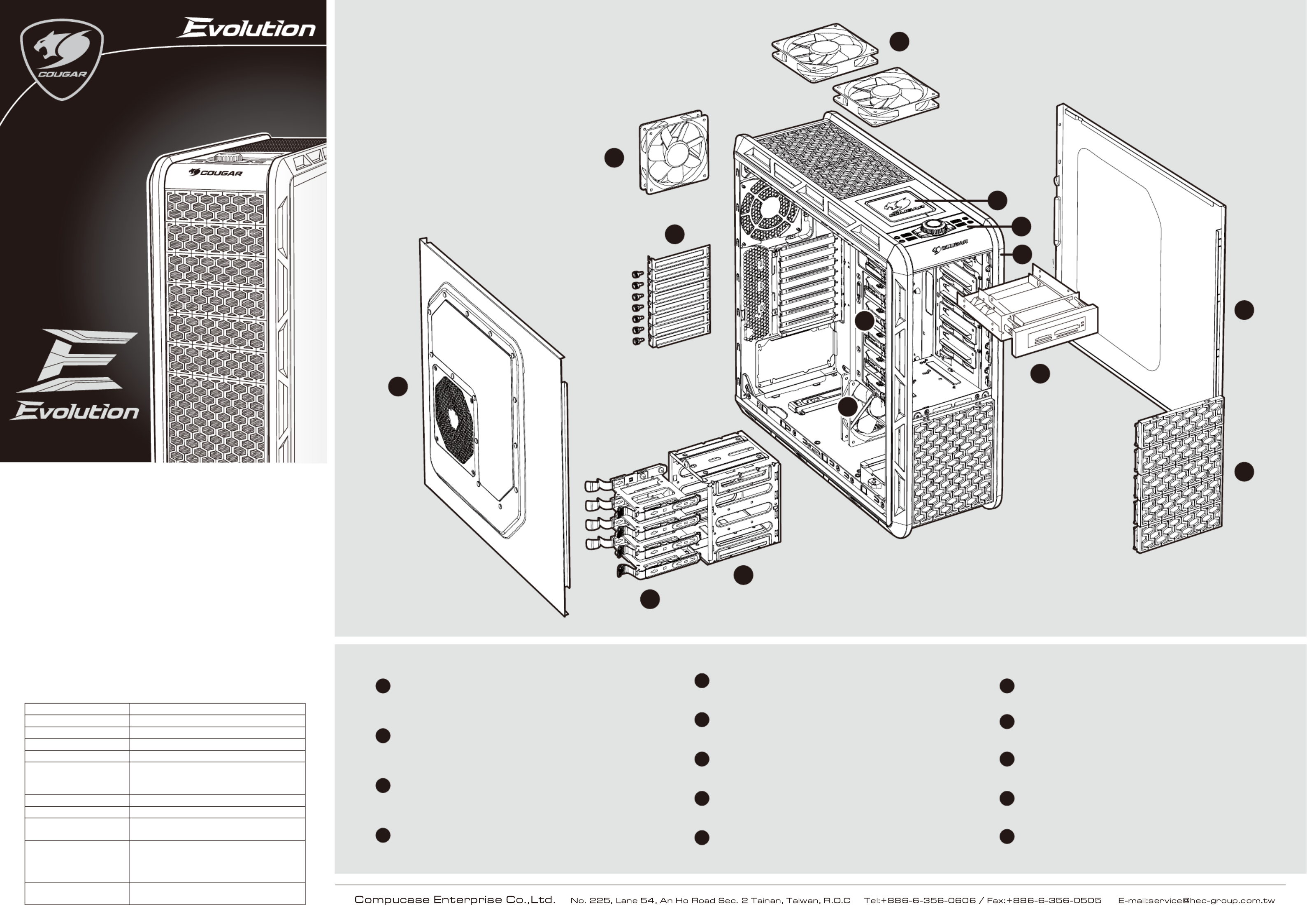
FRight side panel, easily upgrade your hardware system
GTool-less 5.25”drive bays, provide plenty of expansion
HRemovable 3.5”HDD cage for easily install front fan
A
Innovative & Integrated UI for user friendly design, including
USB3.0x2/USB2.0x2/audio/mic, dual way fan control system
can quickly adjust cooling performance & noise level
Top access external 3.5”& 2.5”HDD/SSD for easy mobile
data transfer
120mm fan x 2 for top cover, can rapidly exhaust the
hot air, keep the inner temperature cool
Front panel, removable to easily install 5.25”devices
B
C
D
Unique honeycomb & mesh hybrid intake design 5.25”shield
E
IShockproof HDD tray design for 3.5”HDD and compatible
for 2.5”HDD/SSD
J120mm fan for rear cover, can rapidly exhaust the hot air,
keep the inner temperature cool
KEight PCI slots provides flexibility for multiple graphics
card solutions
Left side cover with 140mm fan intake design
L
120mm fan for front panel, effectively cool the HDD & Graphic Card
M
5.25”to 3.5”conversion kit adapt to 3.5”device or card reader
N
Case Type Middle Tower
Dimension (W / H / D) 223 ( W ) x 523 ( D ) x 514 ( H ) mm
housing material 0.7mm SECC-Steel
Motherboards ATX / Micro ATX
5.25" Drive Bay 6 Exposed
3.5" Drive Bay
4 Hidden
1 Exposed
Converted from one 5.25”drive bay
Hot swap bay 3.5"/2.5" x 1
Expansion Slots 8
I/O Panel MIC x 1
HD Audio x 1
USB 3.0 x 2
USB 2.0 x 2
Cooling System
Front: 120mm fan x 1
Top: 120mm fan x 2
Rear: 120mm fan x 1
Side: 140mm fan x 1 (optional)
Maximum Compatibility CPU cooler height limitation: 180mm
Graphic card length limitation: 305mm

for ODD/FDD/card reader
There are two fan control buttons to control two group fans independently
(fan group A & fan group B)
adapt to 3.5” device
for HDD & main board for cable management
for fanfor cooling water hole
for main board positionfor main board foothold
for main board foothold for PSU & main board
1
3
2
21
Push fan switch button, it will switch to fan control mode,
the green LED lights
Rotate the fan control button to adjust the fan speed
clockwise: faster / counterclockwise: slower
Clockwise: faster & brighter when it reaches max.
fan speed, LED will blink
when it reaches min.
fan speed, LED will blink
Counterclockwise: slower
& dimmer
If we stop using fan control it will return to
blue LED light
SELECT FAN GROUP A
USB 2.0
USB 3.0
USB 2.0
USB 3.0
SELECT FAN GROUP B SELECT FAN GROUP A
USB 2.0
USB 3.0
USB 2.0
USB 3.0
SELECT FAN GROUP B
USB 2.0
USB 3.0
USB 2.0
USB 3.0
USB 2.0
USB 3.0
USB 2.0
USB 3.0
Green light
Accessory Kit
Dual-way fan control system
How to install the 5.25”devices. How to install the 3.5”& 2.5 HDD/SSD”
How to install the Fan
Remove the front panel
How to install the 5.25”to 3.5”conversion kit
5.25”to 3.5”conversion kit
Insert the conversion kit into 5.25”cage
How to install / remove the 5.25”devices.
Insert the device into 5.25”drive bay it will be locked automatically
Screw
Remove top cover
Push six hooks under the
top cover
3.5”HDD 2.5”HDD/SSD 3Insert the device into 3.5”HDD bay.
Pull the screw-less grip
remove the 5.25”device
LED will blink
USB 2.0
USB 3.0
USB 2.0
USB 3.0
USB 2.0
USB 3.0
USB 2.0
USB 3.0
LED will blink
A
B
C
B
C
A
Remove
12
3
4
5
6
A
C
DE
SELECT FAN GROUP A SELECT FAN GROUP B
Air In
ABx2
FAN GROUP A
Air Out
Cx3
D E
FAN GROUP B
FAN GROUP A FAN GROUP B
5.25” ODD
Insert
Pull the screw-less grip
remove the conversion kit
The fan control cable can connect with
two group of fans(air in A,B & air out C,D,E)
controlled by the fan switch buttons
FAN GROUP AFAN GROUP B
Fan group A cable max
current loading is 1A
Fan group B cable max
current loading is 1A
Screw
Card reader
Conversion kit
x1 x12
x20
x8
x1
x12
x3
x2
x2
x6
adapt to 3 fans
x2
optional
SELECT FAN GROUP A
USB 2.0
USB 3.0
USB 2.0
USB 3.0
SELECT FAN GROUP B
Blue light
SELECT FAN GROUP A
USB 2.0
USB 3.0
USB 2.0
USB 3.0
SELECT FAN GROUP B
Pull
B
FAN GROUP B
FAN GROUP A
Standby
8secs
Blue lightGreen light
USB 2.0
USB 3.0
USB 2.0
USB 3.0
Push the“START POWER” The blue LED lights when PC power on You can easily install 3.5”HDD or 2.5”HDD/SSD in the top access
external dock
Start Power External 3.5”& 2.5”HDD/SSD dock
3.5” HDD 2.5” HDD/SSD
How to use the hot-swap feature of the external docking:
1.Make sure to install all related drivers that come with your motherboard.
2.Connect the SATA cable to SATA connector on the motherboard.
3.Connect the power cable to power supply.
If your hot-swap device has no function after installation, please refer
to the following settings.
1.Turn on the AHCI function in the BIOS to activate the hot-swap feature.
2.Reinstall your computer operating system.
Specyfikacje produktu
| Marka: | Cougar |
| Kategoria: | Komputerowe przejęcie |
| Model: | Evolution BO |
Potrzebujesz pomocy?
Jeśli potrzebujesz pomocy z Cougar Evolution BO, zadaj pytanie poniżej, a inni użytkownicy Ci odpowiedzą
Instrukcje Komputerowe przejęcie Cougar

30 Marca 2025
2 Stycznia 2025
2 Stycznia 2025
2 Stycznia 2025
2 Stycznia 2025
2 Stycznia 2025
23 Września 2024
22 Września 2024
22 Września 2024
22 Września 2024
Instrukcje Komputerowe przejęcie
- Komputerowe przejęcie Joy-It
- Komputerowe przejęcie Supermicro
- Komputerowe przejęcie Gigabyte
- Komputerowe przejęcie StarTech.com
- Komputerowe przejęcie Asus
- Komputerowe przejęcie MSI
- Komputerowe przejęcie Genesis
- Komputerowe przejęcie Akasa
- Komputerowe przejęcie Cooler Master
- Komputerowe przejęcie Icy Box
- Komputerowe przejęcie Dell
- Komputerowe przejęcie Corsair
- Komputerowe przejęcie NZXT
- Komputerowe przejęcie FSP
- Komputerowe przejęcie Phanteks
- Komputerowe przejęcie Razer
- Komputerowe przejęcie ADATA
- Komputerowe przejęcie Antec
- Komputerowe przejęcie ModeCom
- Komputerowe przejęcie Sharkoon
- Komputerowe przejęcie DeepCool
- Komputerowe przejęcie Chenbro Micom
- Komputerowe przejęcie 3M
- Komputerowe przejęcie XPG
- Komputerowe przejęcie IStarUSA
- Komputerowe przejęcie Silverstone
- Komputerowe przejęcie Thermaltake
- Komputerowe przejęcie Fractal Design
- Komputerowe przejęcie Be Quiet!
- Komputerowe przejęcie HYTE
- Komputerowe przejęcie Savio
- Komputerowe przejęcie Zotac
- Komputerowe przejęcie Lian Li
- Komputerowe przejęcie Techly
- Komputerowe przejęcie Intel
- Komputerowe przejęcie Monoprice
- Komputerowe przejęcie Zalman
- Komputerowe przejęcie Advantech
- Komputerowe przejęcie Evnbetter
- Komputerowe przejęcie Xigmatek
- Komputerowe przejęcie Akyga
- Komputerowe przejęcie Rosewill
- Komputerowe przejęcie AeroCool
- Komputerowe przejęcie Krux
- Komputerowe przejęcie 3R System
- Komputerowe przejęcie SilentiumPC
- Komputerowe przejęcie AZZA
- Komputerowe przejęcie Middle Atlantic
- Komputerowe przejęcie CoolerMaster
- Komputerowe przejęcie Montech
- Komputerowe przejęcie Jonsbo
- Komputerowe przejęcie Kolink
- Komputerowe przejęcie Leba
- Komputerowe przejęcie Hoffman
Najnowsze instrukcje dla Komputerowe przejęcie
9 Kwietnia 2025
7 Kwietnia 2025
5 Kwietnia 2025

3 Kwietnia 2025
1 Kwietnia 2025
1 Kwietnia 2025
1 Kwietnia 2025
30 Marca 2025

29 Marca 2025
28 Marca 2025