Instrukcja obsługi Citizen CL-S6621
Citizen
drukarka etykiet
CL-S6621
Przeczytaj poniżej 📖 instrukcję obsługi w języku polskim dla Citizen CL-S6621 (69 stron) w kategorii drukarka etykiet. Ta instrukcja była pomocna dla 18 osób i została oceniona przez 2 użytkowników na średnio 4.5 gwiazdek
Strona 1/69

CL-S6621
U MSER'S ANUAL
Thermal Transfer Barcode & Label Printer

2
CONTENTS
Before Operation
INTRODUCTION .............................................................................................................................. 3
COMPLIANCE STATEMENT FOR EUROPEAN USERS ........................................................... 4
GS MARK STATEMENT ................................................................................................................... 4
FCC COMPLIANCE STATEMENT FOR AMERICAN USERS ................................................... 4
EMI COMPLIANCE STATEMENT FOR CANADIAN USERS ................................................... 5
ETAT DE CONFORMITE EMI A L’USAGE DES UTILISATEURS CANADIENS .................... 5
IMPORTANT SAFETY INSTRUCTIONS ...................................................................................... 6
NOTICE ............................................................................................................................................... 7
SAFETY INSTRUCTIONS ................................................................................................................ 8
Chapter 1 Setup
Conrmation of Carton Contents ..........................................................................................10
Part Names and Functions ........................................................................................................11
Connection to Power ..................................................................................................................17
Driver Installation ........................................................................................................................17
Connection to a Computer .......................................................................................................18
Chapter 2 Printer Operation
Power ON/OFF ..............................................................................................................................19
Normal Operating Mode ...........................................................................................................20
Setting the Media ........................................................................................................................22
Setting the Ribbon ......................................................................................................................28
Mode Settings ...............................................................................................................................31
Quick Setup of the Print Method ...........................................................................................44
Selecting the Ribbon Winding Direction ............................................................................45
Emulation Auto Detect: Cross-EmulationTM ........................................................................45
Manually Selecting the Printer Emulation ..........................................................................46
Chapter 3 Printer Adjustments
Sensor Adjustments ....................................................................................................................47
Media Thickness Adjustment ..................................................................................................50
Media Width Adjustment ..........................................................................................................51
Adjusting the Ribbon .................................................................................................................52
Cleaning ..........................................................................................................................................54
Appendixes
Troubleshooting ...........................................................................................................................55
Specications ................................................................................................................................58
Interfaces ........................................................................................................................................62

3
■■■
Main Features
■■■
<High-speed, high-quality printing>
This printer can be used for high-speed high-quality printing thanks to its direct thermal method
and thermal transfer method that use a line thermal printhead together with its 32 bit RISC CPU
and its ‘history control IC’.
<Easy operation>
• It is easy to change the printer’s settings on the operation panel, thanks to its unique and
simple VuePrint menu system.
• Its high-lift printhead and mechanism means that media and ribbon can be loaded with
ease and it is constructed for easy thermal printhead cleaning, etc.
• Media width adjustment, media thickness adjustment, and media sensor adjustment can
all be made easily by the user using the colour-coded operator controls.
<Dual Programming Language>
This printer contains both the Datamax® and Zebra® emulations and will automatically
detect the language using the Cross-EmulationTM feature.
<Interface>
An industry standard RS232 serial port and USB2.0 port are standard equipment, for quick
data transfer and printing.
<Optional interface>
Additional connectivity is available with an optional internally-housed IEEE1284 parallel port,
an Ethernet interface and a wireless LAN print server.
<Optional auto-cutter / peeler unit>
The auto-cutter and peeler units are designed so that they can be installed easily.
<Adjustable sensors>
The adjustable media sensors - which allow the sensors to be positioned in dierent
locations across the media - are standard features making the printer ideal for use with
special media.
<Installation>
The interface, power switch etc. are installed towards the back and the top cover opens and
closes vertically so that the sides of the printer are not restricted.
INTRODUCTION
Thank you for purchasing a Citizen CL-series label printer oering high performance thermal transfer
printing on media up to 6 inches wide.

4
COMPLIANCE STATEMENT
FOR EUROPEAN USERS
CE marking shows conformity to the following criteria and provisions:
Low Voltage Directive (2006/95/EC, formerly 73/23/EEC)/EN60950-1
EMC Directive (2004/108/EC, formerly 89/336/EEC)/EN55022, EN55024, EN61000-3-2 &
EN61000-3-3
GS MARK STATEMENT
This product has been tested under EN ISO 7779 and has an acoustic level output no higher than
70dB(A).
This device is not intended for use at a video workstation in compliance with Bildscharb V.
This device is not intended for use in the direct eld of view at visual display workplaces. To avoid
incommoding reections at visual display workplaces this device must not be placed in the direct
eld of view.
FCC COMPLIANCE STATEMENT
FOR AMERICAN USERS
This equipment has been tested and found to comply with the limits for a Class A digital device,
pursuant to Part 15 of the FCC Rules. These limits are designed to provide reasonable protection
against harmful interference when the equipment is operated in a commercial environment.
This equipment generates, uses, and can radiate radio frequency energy and, if not installed
and used in accordance with the instruction manual, may cause harmful interference to radio
communications.
Operation of this equipment in a residential area is likely to cause harmful interference in which
case the user will be required to correct the interference at his own expense.

5
EMI COMPLIANCE STATEMENT
FOR CANADIAN USERS
This Class A digital apparatus complies with Canadian ICES-003.
This equipment generates and uses radio frequency energy and if not installed and used
properly, that is, in strict accordance with the manufacturer’s instructions, may cause interference
to radio and television reception. This digital apparatus does not exceed the Class A limits for
radio noise emissions from digital apparatus set out in the Radio Interference Regulations of the
Canadian Department of Communications. This equipment is designed to provide reasonable
protection against such interference in a residential installation. However, there is no guarantee
that interference will not occur in a particular installation. If this equipment does cause
interference to radio or television reception, which can be determined by turning the equipment
off and on, the user is encouraged to try to correct the interference by one or more of the
following measures:
• Reorient or relocate the receiving antenna.
• Increase the separation between the equipment and receiver.
• Connect the equipment into an outlet on a circuit dierent from that to which the receiver is
connected.
• Consult the dealer or an experienced radio/TV technician for help.
CAUTION: Use shielded cables to connect this device to computers.
Any changes or modications not expressly approved by the grantee of this device
could void the user’s authority to operate the equipment.
ETAT DE CONFORMITE EMI A L’USAGE
DES UTILISATEURS CANADIENS
Cet appareil numérique de la classe A est conforme à la norme NMB-003 du Canada.
Cet équipment produit et utilise l’énergie à radiofréquences et s’il n’est pas installé et utilisé
correctment, c’esst à dire en accord strict avec les instructions du fabricant, il risque de provoquer
des intérferences avec la réception de la radio et de la télévision.
Le présent appareil numérique n’émet pas de bruite radio électriques dépassant les limites
applicables aux appareils numériques de la classe A prescrites dans le Réglement sur le
brouillage radioélectrique édicté par le ministère des Communications du Canada.
Cet équipment est conçu pour fournir une protection satisfaisante contre de telles interférences
dans une installation résidentielle. Cependant, il n’y a pas de garantie contre les interférences
avec les réceptions radio ou télévision, provoquées par la mise en et hors circuit de l’équipment;
aussi, il est demandé a l’utilisateur d’essayer de corriger l’interférence par l’une ou plus des
mesures suivantes:
• Réorienter l’antenne de réception.
• Installer l’ordinateur autre part, par égard pour le récepteur.
• Brancher l’ordinateur dans une prise de courant diérente de façon à ce que l’ordinateur et le
récepteur soient branchés sur des circuits diérents.

6
IMPORTANT SAFETY INSTRUCTIONS
• Read all of these instructions and save them for later reference.
• Follow all warnings and instructions marked on the product.
• Unplug this product from the wall outlet before cleaning. Do not use liquid or aerosol cleaners. Use a
damp cloth for cleaning.
• Do not use this product near water.
• Do not place this product on an unstable cart, stand or table. The product may fall, causing serious
damage to the product.
• Slots and openings on the cabinet and the back or bottom are provided for ventilation.
To ensure reliable operation of the product and to protect it from overheating, do not block or cover these
openings. The openings should never be blocked by placing the product on a bed, sofa, rug or other
similar surface. This product should never be placed near or over a radiator or heat register. This product
should not be placed in a built-in installation unless proper ventilation is provided.
• This product should be operated from the type of power source indicated on the marking label.
If you are not sure of the type of power available, consult your dealer or local power company.
• This product is equipped with a three-pronged plug, a plug having a third (grounding) pin. This plug will
only t into a grounding-type power outlet. This is a safety feature. If you are unable to insert the plug into
the outlet, contact your electrician to replace your obsolete outlet. Do not defeat the safety purpose of the
grounding-type plug.
• Do not allow anything to rest on the power cord. Do not locate this product where the cord will be walked
on.
• If an extension cord is used with this product, make sure that the total of the ampere ratings on the
products plugged into the extension cord do not exceed the extension cord ampere rating. Also, make
sure that the total of all products plugged into the wall outlet does not exceed 15 amperes for 120V outlet
and 7.5 amperes for 220V-240V outlet.
• Never push objects of any kind into this product through cabinet slots as they may touch dangerous
voltage points or short out parts that could result in a risk of re or electric shock. Never spill liquid of any
kind on the product.
• Except as explained elsewhere in this manual, don't attempt to service this product yourself. Opening and
removing those covers that are marked "Do Not Remove" may expose you to dangerous voltage points or
other risks. Refer all servicing on those compartments to service personnel.
• The mains plug on this equipment must be used to disconnect mains power. Please ensure that the socket
outlet is installed near the equipment and shall be easily accessible.
• Unplug this product from the wall outlet and refer servicing to qualified service personnel under the
following conditions:
A. When the power cord or plug is damaged or frayed.
B. If liquid has been spilled into the product.
C. If the product has been exposed to rain or water.
D. If the product does not operate normally when the operating instructions are followed. Adjust only
those controls that are covered by the operating instructions since improper adjustment of other
controls may result in damage and will often require extensive work by a qualied technician to restore
the product to normal operation.
E. If the product has been dropped or the cabinet has been damaged.
F. If the product exhibits a distinct change in performance, indicating a need for service.

7
CITIZEN is a registered trademark of CITIZEN HOLDINGS CO., Japan.
CITIZEN es una marca registrada de CITIZEN HOLDINGS CO., Japón.
Copyright © 2012 by CITIZEN SYSTEMS JAPAN CO., LTD.
NOTICE
• Before use, be sure to read this manual. And keep it handy for reference when needed.
• The contents of this manual may change without prior notice.
• Reproduction, transfer, or transmission of the contents of this manual without prior consent is strictly
prohibited.
• We are not liable for any damage resulting from the use of the information contained herein, regardless of
errors, omissions, or misprints.
• We are not liable for any problems resulting from the use of optional products and consumable supplies
other than the designated products contained herein.
• Do not handle, disassemble or repair the parts other than those specied in this manual.
• We are not liable for any damage caused by user's erroneous use of the printer and inadequate
environment.
• Data residing in the printer is temporary. Therefore, all data will be lost if power is lost. We are not liable for
any damage or loss of prots caused by data loss due to failures, repairs, inspections, etc.
• Please contact us if there are any mistakes or ambiguities within this manual.
• If there are missing or incorrectly collated pages in this manual, contact us to obtain a new manual.

8
SAFETY INSTRUCTIONS
which must be strictly observed !
Indicates a situation which, if not observed and handled
properly, could result in death or serious injury.
Indicates a situation which, if not observed and handled
properly, could result in injury.
• To prevent personal injury or property damage, the following shall be strictly observed.
• The degree of possible injury and damage due to incorrect use or improperly following
instructions is described below.
Never perform the following. If not avoided, these may cause damage or trouble to
the printer or cause the printer to overheat and release smoke and cause burns or an
electrical shock. If the printer is damaged or is malfunctioning, be sure to turn the
printer o immediately and remove the power cord from the outlet, then consult our
service personnel.
• Do not place the printer in a poorly ventilated area, or shut o the air vent of the printer.
• Do not place the printer where chemical reactions occur, such as in laboratories or where air is
mixed with salt or gas.
• Do not use a power voltage or frequency other than those specied.
• Do not plug/unplug the power cord or attach/detach the interface cable by simply grabbing the
power cord or interface cable. Do not pull or carry the printer when the tension of the power cord
or interface cable is increased.
• Do not drop or put foreign matter such as clips and pins into the printer. This may cause problems.
• Do not plug the power cord into an outlet with many loads.
• Do not spill drinks such as tea, coee and juice on the printer or spray insecticide on the printer.
If drink or water is spilled, rst be sure to turn the power o and remove the power cord from the
outlet, then consult our service personnel.
• Do not disassemble or modify the printer.
Discard or safely store the plastic packing bag. This bag should be kept away from
children. If the bag is pulled over a child’s head, it may cause suocation.
: This is a mark to call attention to the reader.
Warning
Caution
Warning
9
• Prior to operation, read the safety instructions carefully and observe them.
• Do not drop or put foreign matter such as clips and pins into the printer. This may cause problems.
• Be careful when moving or carrying the printer. Dropping the printer may cause injury or property
damage.
• Make sure if you open the top cover, it is opened all the way. If only partially open, the cover could
slam shut, possibly causing injury.
• When the cover is open, be careful of the corners of the cover. They could cause injury.
• Do not open the printer during printing.
• When cleaning the surface of the printer case, do not use the cloth that is soaked in thinner,
trichloroethylene, benzine, ketone or similar chemicals.
• Do not use the printer where there is a lot of oil, iron particles, or dust.
• Do not spill liquids or spray insecticide on the printer.
• Do not jolt or impact to the printer by stepping on, dropping or hitting the printer.
• Operate the control panel properly. A careless, rough handling may cause problems or malfunction.
Do not use such sharp-edged tool as a ballpoint pen for operation.
• Be careful of the edges of the plates so injury or property damage is possible.
• If a problem occurs during printing, stop the printer immediately and unplug the power cord from
the outlet.
• When printer trouble occurs, do not try to dissemble it. Instead, consult our service personnel.
Caution
Caution
General Precautions
• Prior to operation, read the safety instructions carefully and observe them.
• Do not use or store the printer near re, excessive moisture, in direct sunlight, near an air conditioner
or heater or other source of unusually high or low temperature or humidity or excessive dust.
• Do not place the printer where chemical reactions occur, such as in a laboratory.
• Do not place the printer where air is mixed with salt or gas.
• The printer must sit on a firm, level surface where there is ample ventilation. Never allow the
printer’s air vent to be blocked by a wall or other object.
• Do not put anything on the top of printer.
• Do not place the printer near a radio or television, and do not use the same wall outlet for the
printer and radio or television. Radio or television reception could be adversely aected.
• Do not put anything on the power cord or step on it.
• Do not drag or carry the printer with the power cord or interface cable.
• Avoid plugging the power cord into an outlet with many loads.
• Do not bundle the power cord when inserting the plug.
• Always grip the plug housing, not the cord, to plug/unplug the power cord.
• Make certain the power is turned o before connecting/disconnecting the interface cable.
• Avoid lengthening the signal cable or connecting it to any noise-producing device. If it is
unavoidable, use the shielded cable or twisted pair for each signal.
• Place the printer near the outlet where the power cord can be unplugged easily to shut o power.
• Use the AC outlet that accepts a three-pronged plug. Otherwise, static electricity may be generated
and there will be danger of electric shock.
Precautions When Installing the Printer
10
Chapter 1 Setup
Chapter 1 Setup
Conrmation of Carton Contents
Removing the Packing Material
The printer is shipped with adhesive tape in place to hold the top cover
closed. Simply remove the two pieces of tape on either side of the top
cover. Then simply open the cover by lifting up and tipping it backwards.
There is another strip of adhesive tape that must be removed which holds
the mechanism closed for shipping. Remove the tape and attached
paper by carefully peeling from the plastic case.
Retain the tape should you need to transport the printer again.
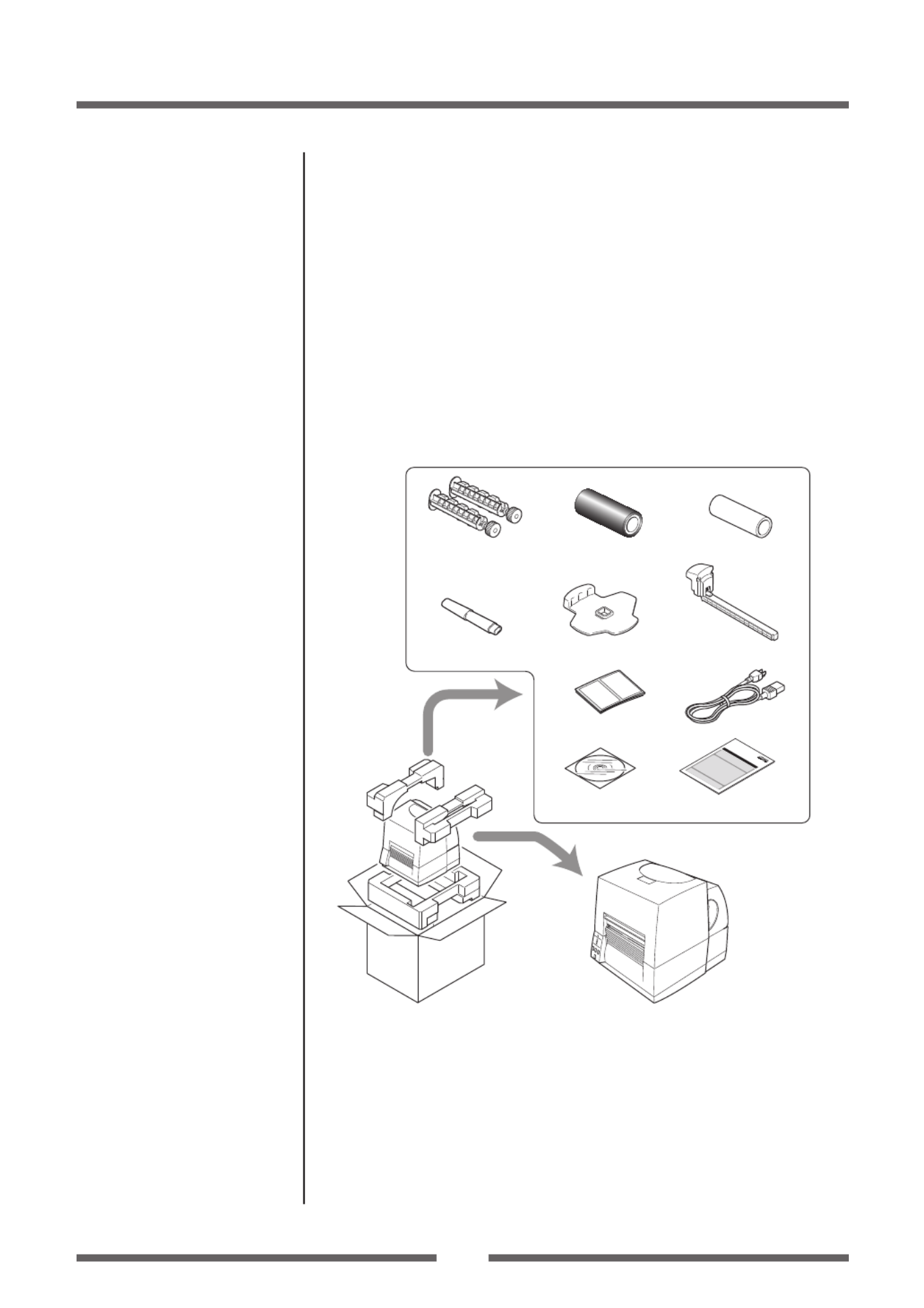
Check that the following accessories are included with the printer in
the carton.
CD-ROM Quick-start Guide
Media holder barMedia holder guide
Head cleaner
Paper CoreSample RibbonRibbon Holder
Test label media Power cord
Printer
Note: The empty carton and packing materials should be stored for
future shipping of the printer.

11
Chapter 1 Setup
• Be careful when moving or carrying the printer and when taking the
printer out of the carton. The printer may cause injury or property
damage if dropped. Be sure to grip the printer housing rmly when
taking it out of the carton. Do not grip the printer by the foam
packing material which may break, causing the printer to drop.
• When opening the cover, open it all the way. If only part way
open, the cover could slam shut, possibly causing injury.
• Be careful of the edge of the cover when the cover is opened. It
may cause injury or property damage.
• Be careful of the edges of the metal plates so injury or property
damage is possible.
Caution
Part Names and Functions
Front View
2
1
5
4
3
1Top cover
Is opened vertically to set media or ribbon.
2Operation panel
This is used to make changes and adjustments to the printer and its
conguration.
3Heat discharge vent
It allows warm air to vent from the printer.
Be sure not to block it with media etc.
4 Ribbon window
The amount of ribbon remaining can be checked through this window.
5 Media window
The amount of media remaining can be checked through this window.
Operation Panel (p.15)

12
Chapter 1 Setup
Part Names and Functions
Inside the printer
2
1
4
3
1
Ribbon drive unit
2
Head close knob
Push the head close knob to lock the mechanism closed. If you push
on another part of the mechanism, the printer may not lock closed
correctly.
3
Ribbon holder
It is used to attach the ribbon and paper core.
4 Front cover
It is removed to install optional units such as the peeler or cutter.

13
Chapter 1 Setup
Part Names and Functions
3
25
6
7
4
1
1
Front (winding side) ribbon tension adjustment knob
This is adjusted according to the width of the ribbon that is used. It is
also used when the ribbon is wrinkled or slips.
2
Front (winding side) ribbon left-right balance adjustment
knob
It is used to perform an adjustment when the ribbon is wrinkled.
Normally set it to the center position.
3
Media width adjustment dial
It is adjusted to match the width of the media.
4 Back (feeding side) ribbon tension adjustment knob
This is adjusted according to the width of the ribbon that is used. Use
it basically in the same way as the front adjustment knob.
5 Back (feeding side) ribbon left-right balance adjustment
knob
It is used to perform an adjustment when the ribbon is wrinkled.
Normally set it to the center position.
6 Media thickness adjustment dial
It is adjusted to match the thickness of the media.
7 Large blue-head open lever
The head unit can be raised to install media by pushing this lever.
It locks the head unit during printing.
Ribbon Tension Adjustment
(p.52)
Ribbon Balance Adjustment
(p.53)
Media Width Adjustment (p.51)
Ribbon Tension Adjustment
(p.52)
Ribbon Balance Adjustment
(p.53)
Media Thickness Adjustment
(p.50)
14
Chapter 1 Setup
Part Names and Functions
-1
-1
-2
-2
2
3
4
1
3
4
57
8
6
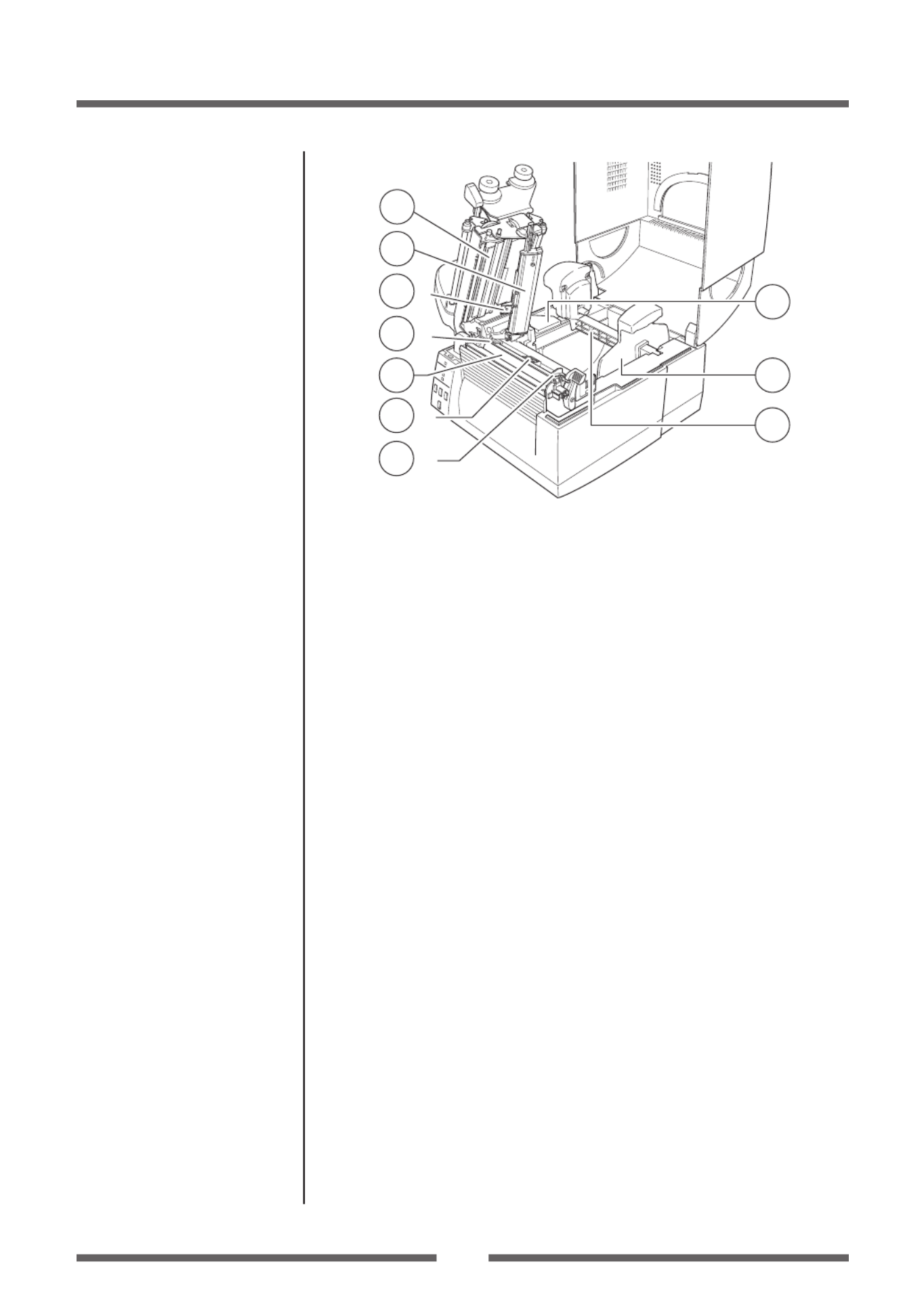
1
Thermal printhead
This is the printhead. Avoid touching this with your ngertips and
leaving grease or dirt on the printhead surface.
2
Sensor arm
The media can be installed by raising this arm.
The media can be held in place by lowering this arm.
3
Upper sensor (3-1) and bottom sensor (3-2)
Used as a transparent sensor or a reective sensor. Settings for sensor
position and sensor adjustment should be performed in accordance
with the type of sensor used.
4 Media guides (Left xed media guide ( 4-1) and right
movable media guide (4-2))
The end of the media is matched to the left xed media guide, then the
right side movable media guide is moved horizontally to match it to the
media size. And the movable media guide is used as a guide to match the
upper sensor and bottom sensor when using the transparent sensors.
5 Platen
Interlocked with the thermal printhead, it feeds media backwards or
forwards.
6 Optional unit connector cover
It is opened when the cables of the cutter unit and the peeler unit are
connected. Do not remove during normal use.
7 Media holder guide
This guide is moved horizontally to match the media size.
The guide can be sliding it from the holder bar.
8 Media holder bar
The media is supported by the media holder bar when installed in the
printer.
Setting sensor positions (p.24)
Sensor Adjustments (p.47)
Installing the Media (p.25)

15
Chapter 1 Setup
Part Names and Functions
Operation Panel
1
2
3
4
5
6
8
7
1
POWER LED
This is lit when the printer power is on. (green)
2 PRINT LED
This is lit when the printer is able to print. (green)
3 CONDITION LED
This is on when selecting settings. (orange)
4 ERROR LED
This is lit or ashes when the printer is in an alarm or error status. (red)
5 PAUSE key
This temporarily stops printing.
6 FEED key
This key feeds the media to the top of the next label or form.
7 STOP key
This stops printing or cancels the alarm.
8 MODE/REPEAT key
This key exits current status in the menu setting mode or reprints the
nal label, depending on printer status.
LED Functions (p.21)
Normal Operating Mode (p.20)

16
Chapter 1 Setup
Part Names and Functions
Rear View
1
3
4
5
2
1 Serial interface (RS232C)
This receives serial transmission of data from a host computer.
2 Option interface
Additional option interface boards can be mounted. Contact your
retailer if you want to use the option interface.
3 USB interface
This receives USB transmission of data from a host computer.
4 Power switch
The is the power switch for the printer.
5 Power cord inlet
The connector of the enclosed power cord is connected here.
Serial Interface (p.62)
USB Interface (p.64)
Power ON/OFF (p.19)
Connection to Power (p.17)

17
Chapter 1 Setup
Connection to Power
1. Check that the power switch to the printer is turned OFF.
2. Connect the connector of the power cord to the power cord
inlet on the printer.
3. Insert the plug of the power cord in the AC outlet.
AC Outlet
Power Cord Inlet
Power Switch
Use an AC outlet that accepts a three-pronged plug. Otherwise, static
electricity may be generated and there will be danger of electric shock.
Caution
Driver Installation
The computer may automatically detect the presence of the new printer
when it is rst started, depending on the computer type, interface and
operating system. Follow any on-screen instruction and also instructions
supplied with any additional CD-ROM included with your printer.
Your supplier will assist you with the correct drivers and software which
are compatible with your particular computer system.
Do not use any voltage other than that displayed. Doing so may lead to
damage or malfunction.
Caution

18
Chapter 1 Setup
Connection to a Computer
This product has two interfaces that can be used to receive printing
data: a serial port (RS232C) and a USB port (USB2.0). An optional internal
Ethernet, an IEEE1284 Parallel or Wireless LAN port can be added by your
dealer.
With the exception of a wireless LAN connection, an interface cable is
necessary to connect the printer to a computer.
To connect the cable, proceed as follows:
1. Turn OFF both power switches of the printer and the
computer.
2. Connect one end of the interface cable to the interface
connector on the back of the printer and secure it with locks
or locking screws, where available.
3. Connect the other end of the interface cable to the interface
connector on the computer and secure it with locks or
locking screws, where available.
Serial Interface Cable
USB Interface Cable
Note: If an optional Ethernet, an IEEE1284 Parallel or Wireless LAN port is
used, contact your Citizen Systems dealer.
Serial Interface (p.62)
USB Interface (p.64)

19
Chapter 2 Printer Operation
Chapter 2 Printer Operation
Power ON/OFF
Turning on the power
1. Turn on the power switch on the back of the printer.
2. The POWER and PRINT LED are lit.
Power Switch
Operation Panel
Turning o the power
1. Turn o the power switch on the back of the printer.
2. The POWER and PRINT LED go o.
Power Switch

20
Chapter 2 Printer Operation
Menu Setup Mode (p.33)
Normal Operating Mode
When the power is turned on, the printer enters normal operating mode.
The control keys activate the following functions.
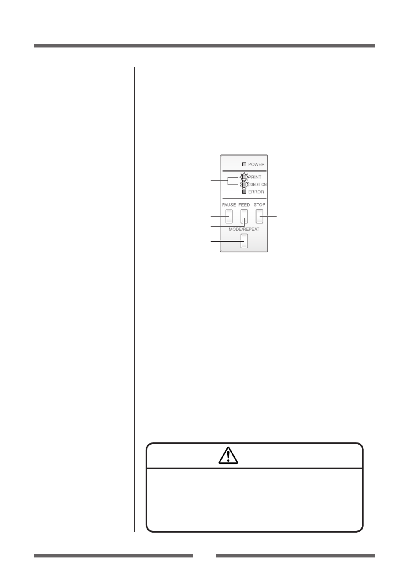
1
2
4
3
1 PAUSE key: Temporarily pauses printing
• When this key is pushed once, the PRINT LED turns o and the
printer temporarily pauses.
• When it is pushed during printing, the printer pauses after the label
currently being printed is issued. Pressing the key a second time
restarts printing and the remaining number of designated labels are
printed.
2 FEED key: Feeds media
• Pressing this key feeds media to the print start position.
The distance it is fed is determined by automatically detecting
the front end of the media when using label media, and when
continuous media has been designated, a xed quantity is fed, then
feeding stops.
• When the TEAR OFF setting is eective, feeding stops when the
media has been fed to the TEAR OFF location.
• When the optional cutter unit is installed, the media is fed to the cut
position then it is cut.
• If the optional peeler unit is installed, the media is fed to the peeling
location. When the media is pausing at the peeling position, feeding
does not occur, even if the FEED key is pushed.
3 STOP key: It stops printing and cancels the alarm
• Pushing this key once during printing puts the printer in pause
mode after the label is issued. It is possible to cancel 1 batch of label
issuing data by pressing the STOP key for 4 seconds or longer in
pause status. (The PRINT LED ashes at high speed during cancel.)
4 MODE/REPEAT key:
• Pressing this key reprints the last label in PRINT status (when the
PRINT LED is lit) The last label issued depends on the selection of
the "MODE/REPEAT key" menu.

21
Chapter 2 Printer Operation
Normal Operating Mode
LED Functions
1 POWER LED
It lights up when printer power is
turned on. (green)
2 PRINT LED
This is lit when the printer is able to
print. (green)
3 CONDITION LED
This is on when selecting settings.
(orange)
4
ERROR LED
This is lit or ashes when the printer is in error status. (red)
Table of Alarm and Error Indications
In addition to normal operating mode, when an abnormal condition is
detected in the printer, an alarm sounds and each LED either lights up or
ashes to indicate the type of error.
Item PRINT LED CONDITION
LED ERROR LED
When the STOP key has been pushed
OFF OFF OFF
Abnormal head temperature
ON ONOFF OFF OFF
Abnormal motor temperature ON OFF ONOFF OFF
Head open OFF OFF
Media end OFF OFF ON OFF
Media out
(media location cannot be detected) OFF ON ONOFF OFF
Abnormal head resistance OFF ON OFF ONOFF
Ribbon feed error OFF
Ribbon end OFF
Communication error
(reception buer overrun)
OFF ON OFF OFF
Communication error
(parity, framing)
Communication error
(transmission buer overow)
System error OFF ON
Auto cutter abnormality
(jamming etc.) OFF OFF ON
Auto cutter temperature abnormal ON OFF ONOFF OFF
Paper near end* ON OFF ON OFF
* Only displayed when the Paper Near End Alarm setting under Menu Setup Mode is On.
The buzzer will not sound while the alarm is displayed.
Time Axis → : ON, : OFF
Wide on/o marks indicate slow LED ashing.
Small circle on/o marks indicate quick LED ashing.
1
2
3
4

22
Chapter 2 Printer Operation
Menu Setting Table (p.38)
Setting the Media
Media Sizes
The position of label and tag media is sensed by either a transparent
sensor or a reective sensor.
Transparent sensor: Detects the gaps between label media and notches
of tag media
Reective sensor: Detects the black mark
A
I
I
G
H
D
KK
F E
B
Notch detection Black mark detection
J
L
N
M
Transparent sensor
Continuous media
Label
Label
Label
Printed area
Reective sensor
Media direction
Label media
C
Min. value mm (inches) Max. value mm (inches)
A Label width 50.0 (1.97) 178.0 (7.01)
B Liner width 50.0 (1.97) 178.0 (7.01)
C Label left edge position 0 (0) 2.54 (0.10)
D
Length of gap between labels
3 (0.12) 2539.7 (99.99)
E Label length 16 (6.30) 2539.7 (99.99)
F Label pitch 19 (7.48) 2539.7 (99.99)
G Liner thickness 0.06 (0.0025) 0.125 (0.0049)
H Total media thickness 0.06 (0.0025) 0.25 (0.01)
I
Position of right edge of notch
6.00 (0.24) 60.80 (2.39)
J
Position of left edge of notch
0 (0) 57.20 (2.25)
K Notch length 2.54 (0.10) 17.80 (0.70)
L Right edge of black mark 15.00 (0.59) 66.50 (2.62)
M Left edge of black mark 0 (0) 51.5 (2.02)
N Black mark width 3.18 (0.125) 17.80 (0.70)
* Use a transparent sensor for label media gaps and media with black marks.
*Use a transparent sensor for fan fold media.
* If the label pitch is 1 inch or less, set the Small Media Adjustment menu to ON
and match it to the label that uses the value of the Small Media Length menu.
23
Chapter 2 Printer Operation
Setting the Media
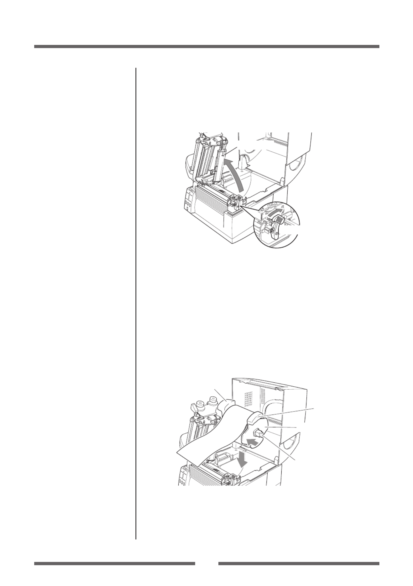
Installing the Media
1. Push the large blue-head open lever to release the head
unit, and then lift the sensor arm by hand as shown below.
Sensor arm
Large blue-head open lever
Head unit
2. Firstly, slide the two black plastic parts of the media holder
assembly together. Ensure correct alignment of the guide
with the bar as it can only be installed in one direction.
When using the Paper Near End Sensor, sensor position
settings should be performed. See “Setting the Paper Near
End Sensor” for how to perform the settings. (These settings
are o when the product is shipped from the factory)
3. Slide the roll of media over the media bar. The media guide
must be on the right side of the roll of media (as viewed from
the front of the printer) with the ribbed surface of the media
guide touching the media roll as shown in the illustration.
Media holder bar
Media holder guide
Handle
Handle
4. Set the media roll and media holder in to the printer as shown
above. It is advisable to pull a length of media forwards and
through the mechanism ready for later positioning. When lifting
the media, use the handles on the media holder placed on either
side.
Media Sizes (p.22)
Setting the Paper Near End
Sensor (p.27)

24
Chapter 2 Printer Operation
Setting the Media
5. Move the media roll so it is touching the leftside of the
housing. Then slide the black media guide so it is touching
the media on the right side.
Note: Do not try to hold the media too tightly with these guides as it will
cause the printer to jam during printing.
6. Setting sensor positions.
Lower the sensor arm and turn the knob, the upper sensor
and bottom sensor will both move together.
Knob
Bottom sensor
Upper sensor
Sensor arm
When using a transparent sensor
Move the upper sensor and bottom sensor close to the center of the
width of the media.
When using media that is 6 inches wide, position the upper sensor
and the bottom sensor all the way to the right (large blue-head open
lever side).
Quick Sensor Selection Method
(Transparent Reective) (p.47)
Adjusting the Transparent
sensor (p.48)
25
Chapter 2 Printer Operation
Setting the Media
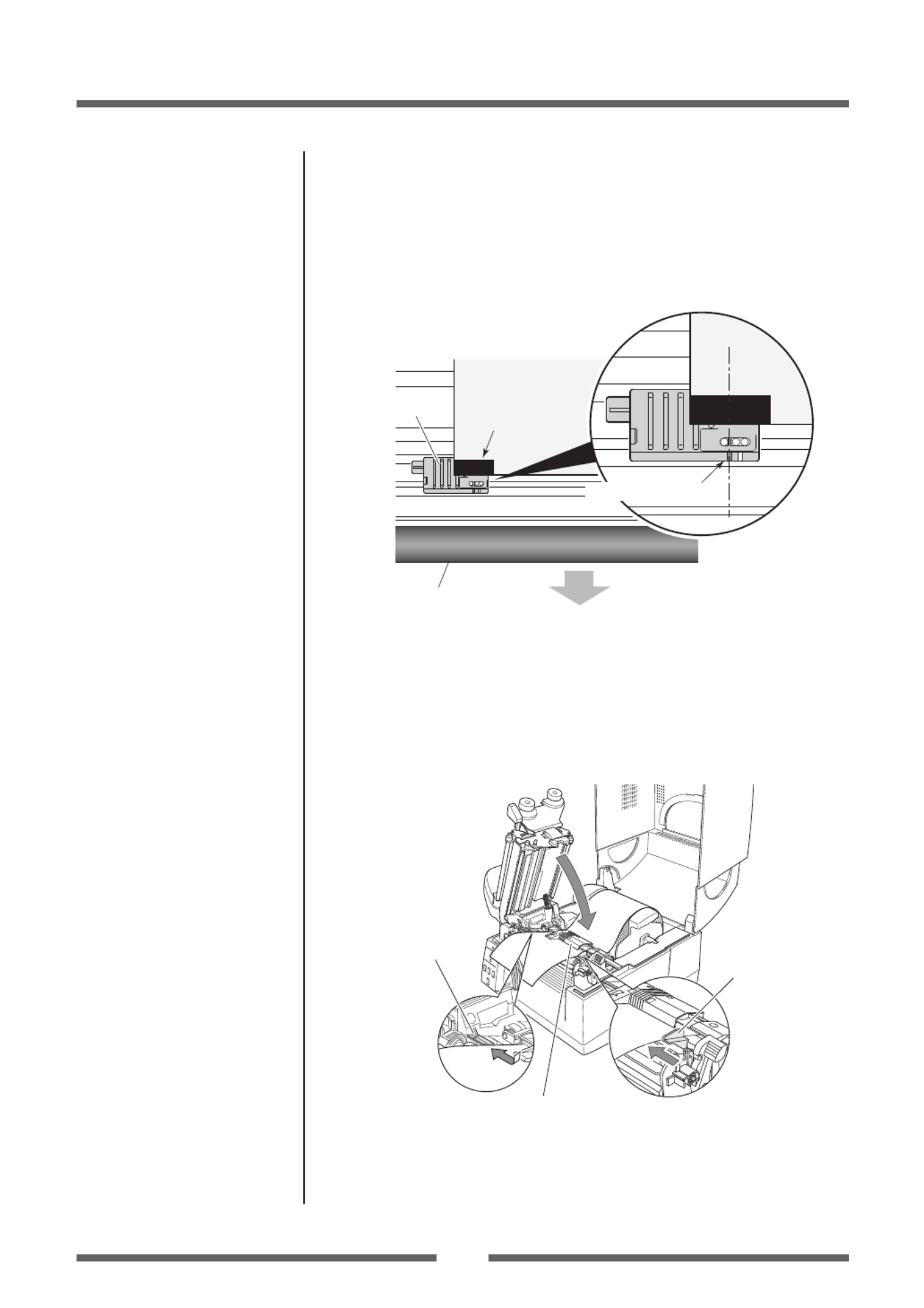
When using a reective sensor
Adjust the position of the sensor so that the reective sensor marker
of the bottom sensor is at the center of the black mark of the media
as shown below.
Front
Black mark
Media
Bottom sensor
Reective sensor marker
Black mark
Platen
7. Lift the sensor arm up temporarily and adjust the media
guide. Align the media with the xed media guide on the left
side, and then align the moveable media guide on the right
side with the width of the media. Lower the sensor arm and
x the media in place.
Fixed media guide
Movable media
guide
Sensor arm
Adjusting the Reective sensor
(p.49)
26
Chapter 2 Printer Operation
Setting the Media
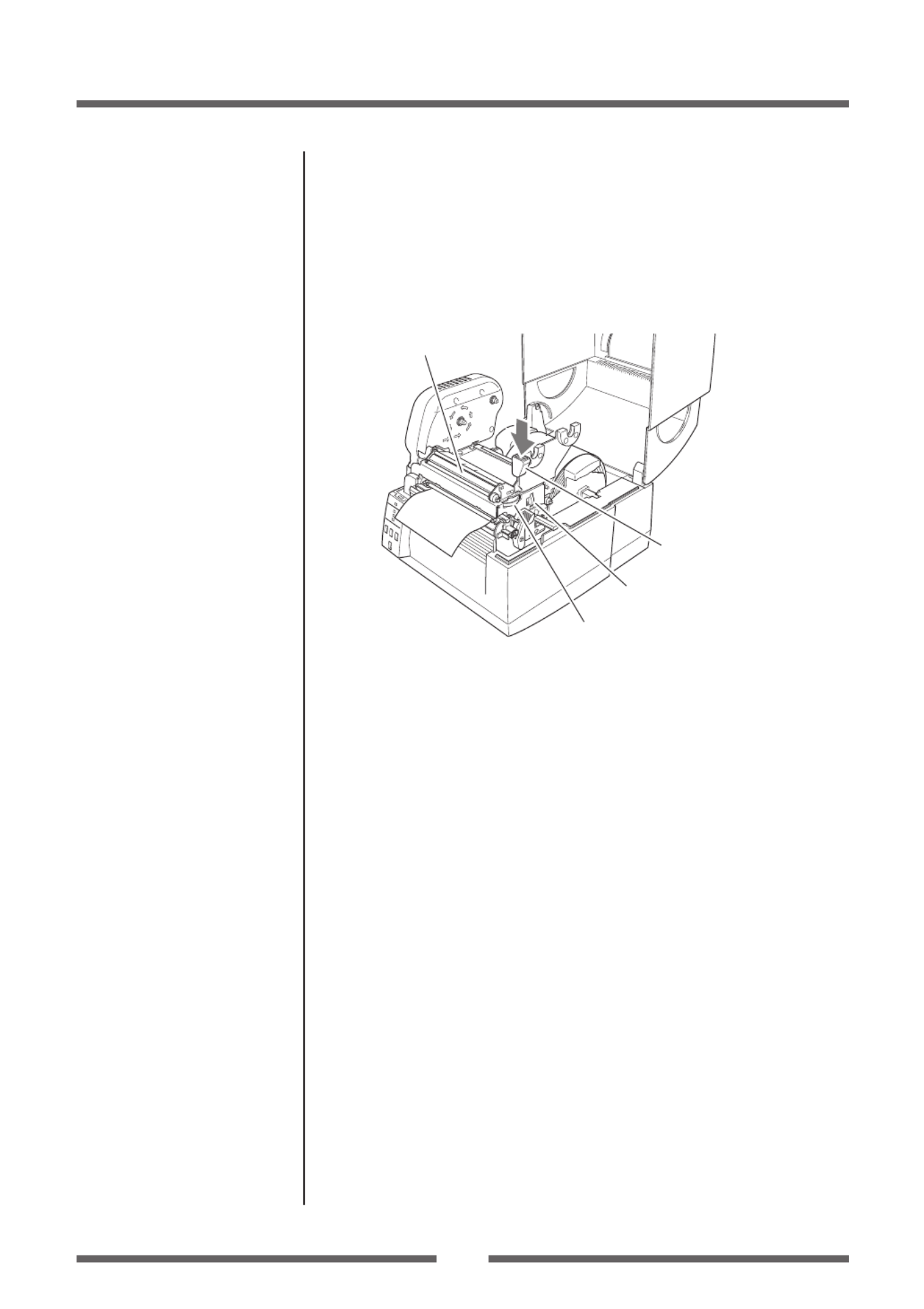
8. Push the head close knob to lower and lock the head unit.
Be sure to always push the head close knob to lock the head
unit. Align it with the width of the media that has been set,
then set the media width and media thickness adjustment
dials. See “Chapter 3 Printer Adjustments”.
Head close knob
Media width adjustment
Media thickness adjustment
Head unit
9. With the power switched on, push the FEED key to feed the
media. It will halt at the next print start position.
Media Thickness Adjustment
(p.50)
Media Width Adjustment (p.51)

27
Chapter 2 Printer Operation
Setting the Paper Near End Sensor
Move the protruding part of the sensor up or down, setting in a position
that matches the roll of media being used.
Media holder bar
Protruding part
Can be adjusted to 6 levels.
1
2
3
4
5
6
Sensor
location Remaining roll of media
1 Approx. 8.5 mm
2 Approx. 7.5 mm
3 Approx. 6.5 mm
4 Approx. 5.5 mm
5 Approx. 4.5 mm
6 Approx. 3.5 mm
Note: • These settings are o when the product is shipped from the
factory.
• The remaining roll of media (thickness of roll of media not
including paper core) diers greatly according to the type of roll
of media used. Use these values only as guidelines.
When not using the Paper Near End Sensor
Disable the Paper Near End Sensor.
With the protruding part of the
sensor housed, push into the top
section until it clicks.
Remaining
roll of media
Paper core
Setting the Media

28
Chapter 2 Printer Operation
Setting the Ribbon
The following kinds and sizes of ribbons can be used.
Types .............................................................
Inside wound and outside wound ribbon
Max. ribbon width ....................................174.0 mm (6.85 inch)
Min. ribbon width ....................................50 mm (1.97 inch)
Max. ribbon length ..................................360.0 m (1,181 ft)
Max. roll diameter ....................................74.0 mm (2.90 inch)
Inner diameter of the paper core .......25.4 ± 0.25 mm (1.00 ± 0.01 inch)
Outer diameter of the paper core ......33.4 ± 0.5 mm (1.31 ± 0.02 inch)
Lead tape length ......................................Less than 80.0 mm
Setting method
1. Check the kind of ribbon used and set the ribbon winding
direction using menu setup mode or operation panel. This
is the method for installing an outside wound ribbon (also
known as “ink out”).
Remember, the inked surface should be facing AWAY from
the printhead surface!
2. Place the attached ribbon and paper core separately on one
of the two attached ribbon holders. Insert the two ribbon
holders into the ribbon and paper cores ensuring that they
are pushed in all the way.
Ribbon holders
Paper core
Ribbon
Selecting the ribbon winding
direction (p.38, p.45)

29
Chapter 2 Printer Operation
Setting the Ribbon
3. Install the unused ribbon and holder in to the rear ribbon
drive unit. The splines on the ribbon drive gear mechanism
engage with the end of the ribbon holder.
12
4. Push the large blue-head open lever to release the head
unit. Pull out the ribbon from the bottom of the head unit to
the ribbon winding side.
5. Using the adhesive leader of the ribbon or some adhesive
tape, x the ribbon that you have pulled out on the ribbon
holder on which the paper core has been set and wind it on
the ribbon holder.
Winding side
ribbon holder
Winding side
ribbon holder

30
Chapter 2 Printer Operation
6. Set the ribbon holder on which the paper core has been set
in the ribbon drive unit, then rotate it in the direction shown
by the arrow to remove slack and wrinkles from the ribbon.
7. Push the head close knob to lower and lock the head unit.
Be sure to always push the head close knob to lock the
head unit. If the ribbon is wrinkled, push the FEED key until
the wrinkles disappear. If the wrinkles do not disappear or
if it slips, perform ribbon balance adjustment and ribbon
tension adjustment. See “Chapter 3 Printer Adjustments” for
these adjustment methods.
Head close knob
Setting the Ribbon
Ribbon Tension Adjustment
(p.52)
Ribbon Balance Adjustment
(p.53)

31
Chapter 2 Printer Operation
Mode Settings
Turning on the power while pressing keys in the following combinations
starts various functions.
Mode Key operation
HEX dump mode Turning power on while pushing the STOP key.
Self print mode Turning power on while pushing the FEED key.
Menu setting mode Turning power on while pushing the MODE/REPEAT key.
HEX Dump Mode
When using label media
Turn on printer power while pushing the STOP key. If the PRINT LED
has begun to ash slowly, release the STOP key, and then the printer
enters HEX DUMP mode.
When using continuous media
Turn on printer power while pushing the STOP key. If the PRINT LED
has stopped ashing slowly and begun to ash rapidly, release the
STOP key, and then the printer enters HEX dump mode.
DUMP LIST
* To exit HEX Dump Mode, turn o the power to the printer then turn the
power on again (restart).
Operation Panel (p.15)

32
Chapter 2 Printer Operation
Self Print Mode
Performing a self test print is an easy way to check on the state of printer
setting and printing quality. Install the media as explained in “Installing
the Media” and then operate the printer as follows.
Case of label media
Turn on printer power while
pushing the FEED key. When the
PRINT LED has begun to ash
slowly, release the FEED key.
After it enters TEST MODE and
media has fed, two labels print
then printing stops.
To restart printing, press the
FEED key once more.
Case of continuous media
Turn on printer power while
pushing the FEED key. When the
PRINT LED has stopped ashing
slowly and has begun to ash
rapidly, release the FEED key.
After it enters TEST MODE and it
prints then printing stops.
To restart printing, press the FEED key once more.
Media Adjustments
Using the Self Test Print shown above, you can make adjustments to the
printer settings such as media width and media thickness (printhead
pressure). The location of these two adjustments is explained in Chapter
3 and also shown on the labels on the printer’s mechanism.
The rst sample, left, shows an incorrectly set
“media thickness adjustment”. For standard label
media, it is recommended you set the blue dial
to the “0” position.
The second sample, left, shows an incorrectly set
“media width adjustment”. For 6-inch or 150mm
wide media, the adjuster should be set to the “9”
position on the blue dial.
The settings shown above are for general label
media and may not apply to specialist media.
Mode Settings
Setting the Media (p.22)
Self print pattern
Media feed
direction
Media Thickness Adjustment
(p.50)
Media Width Adjustment (p.51)
33
Chapter 2 Printer Operation
Mode Settings
When you are changing a menu value, pressing the “PAUSE” key
(YES) causes the printer to save the currently selected parameter.
The CONDITION LED ashes briey. Do not turn o the power to the
printer at this time as this may cause a malfunction.
If the power is accidentally turned o, rst reset the printer to
factory defaults.
Menu Setup Mode
If the printer power is turn on while the MODE/REPEAT key is pressed, the
printer enters menu setup mode. In this mode, the printer’s conguration
can be changed using the VuePrint Menu System. During menu setting
mode, the PRINT LED and CONDITION LED are on. Media must be
installed in the printer to use the VuePrint menu system.
YES/Select/Save
Next digit
Exit to previous menu
NO/Next Item/Change Value
Light up
Functions of the keys
After each menu item is printed, the printer will also print the function
of each of the buttons at that time. They vary slightly depending on the
menu selected but generally t the following guidelines:
PAUSE key (YES/Select/Save):
It is pushed to either select the current menu option or to save the
new setting after which it advances to the next menu.
STOP key (NO/Next Item/Change Value):
Whilst changing a menu value (such as head temperature), pressing
this key displays the next menu value available but does not save the
setting.
In the “main menu“, pressing this key moves to the next menu available.
FEED key (Next digit):
With some menu options such as head temperature, there is more
than one “digit” than can be changed.
This key moves the cursor to the next digit.
MODE/REPEAT key (Exit to previous menu):
Exits the current menu or the VuePrint menu system.
Caution

3
Chapter 2 Printer Operation
Mode Settings [Datamax® Emulation]
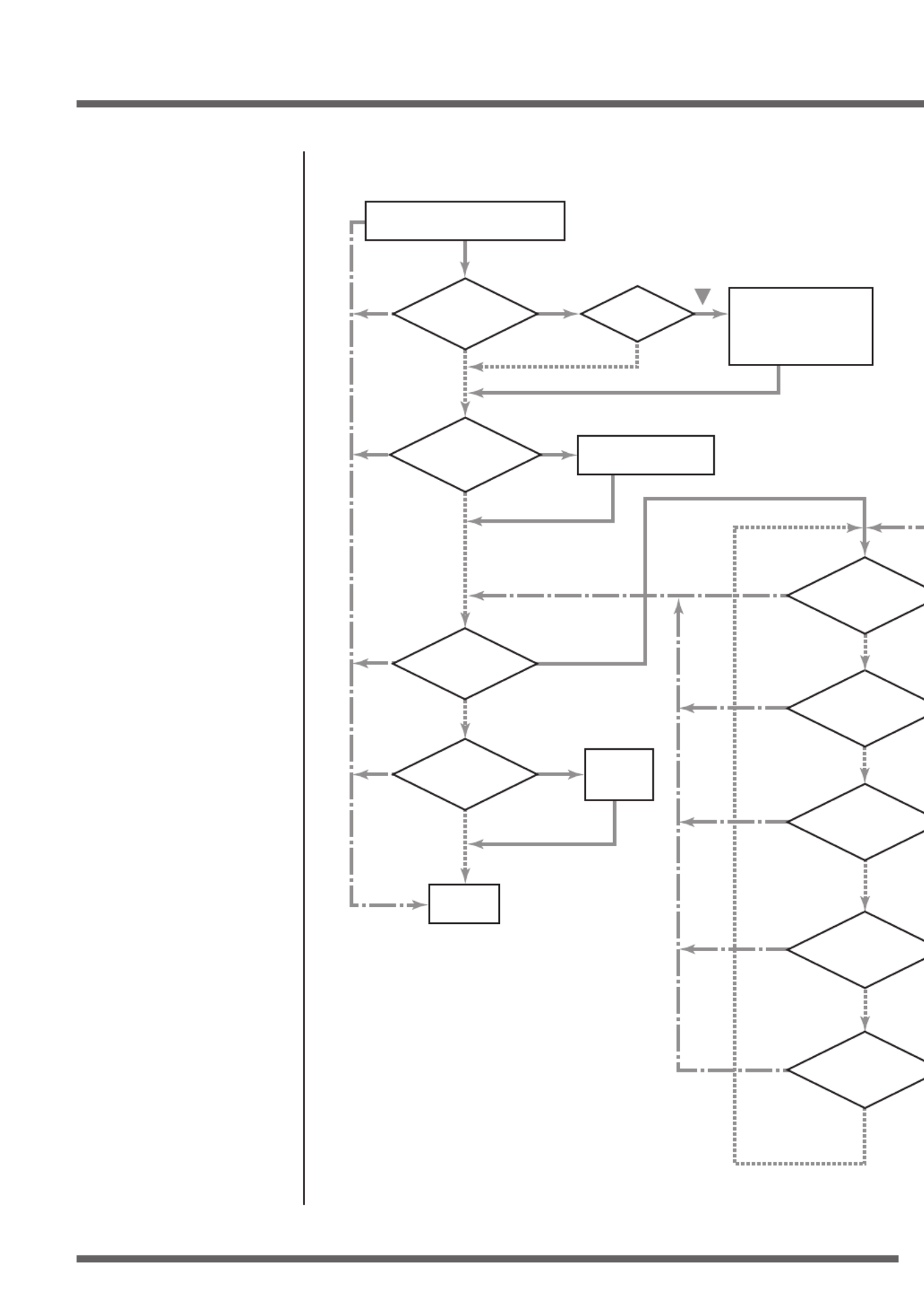
Menu Setting Flow Chart
The following is a ow chart showing the CL-S6621 VuePrint menu system.
Datamax® Emulation
YES
Press FEED key
for 3 seconds
NO NO
NO
YES
YES
NO
NO
YES
NO
EXIT
EXIT
EXIT
EXIT
EXIT
EXIT
EXIT
EXIT
EXIT
NO
NO
NO
MODE/REPEAT key + Power on
Are you sure?
Do you want to
print the current menu
settings?
Completed
Do you want to
change the
menu
settings?
Do you want
to print the current
menu settings?
Do you want to
change "Page Setup
Menu" items?
Do you want to
change "System Setup
Menu" items?
NO
Do you want to
change "Global Cong
Menu" items?
Do you want to
change "After Print
Menu" items?
Do you want to
change "Interface
Menu" items?
Initialization of the
content of the settings
(Initialization to the
settings when the
printer was shipped.)
Printing the contents
of the present setting
Printing the
content of
the changes
Do you
want to reset this
printer to factory
settings?
Menu Setup Mode (p.33)
Printing during top menu
setting (p.36)
Printing of contents of settings
(p.37)
Printing during sub menu
setting (p.36)
3
Chapter 2 Printer Operation
Mode Settings [Zebra® Emulation]
Zebra® Emulation
YES
Press FEED key
for 3 seconds
NO NO
NO
YES
YES
NO
NO
YES
NO
EXIT
EXIT
EXIT
EXIT
EXIT
EXIT
EXIT
EXIT
EXIT
NO
NO
NO
MODE/REPEAT key + Power on
Are you sure?
Do you want to
print the current menu
settings?
Completed
Do you want to
change the
menu
settings?
Do you want
to print the current
menu settings?
Do you want to
change "Page Setup
Menu" items?
Do you want to
change "System Setup
Menu" items?
NO
Do you want to
change "Global Cong
Menu" items?
Do you want to
change "After Print
Menu" items?
Do you want to
change "Interface
Menu" items?
Initialization of the
content of the settings
(Initialization to the
settings when the
printer was shipped.)
Printing the contents
of the present setting
Printing the
content of
the changes
Do you
want to reset this
printer to factory
settings?
Menu Setup Mode (p.33)
Printing during top menu
setting (p.36)
Printing of contents of settings
(p.37)
Printing during sub menu
setting (p.36)

36
Chapter 2 Printer Operation
Mode Settings
This particular example is changing the print speed and print darkness
then continues through the remainder of the “Print Setup” menu.
The actual output from the printer is “vertically reversed” due to the way
the printer outputs the menu options. Please look at the example below
to see how the output changes.
Printing during top menu setting
<Example of CL-S6621 Datamax® emulation selected>
Printing during sub menu setting
<Example of CL-S6621 Datamax® emulation selected>
Menu Setting Flow Chart (p.34)
Menu Setting Flow Chart (p.34)
Specyfikacje produktu
| Marka: | Citizen |
| Kategoria: | drukarka etykiet |
| Model: | CL-S6621 |
Potrzebujesz pomocy?
Jeśli potrzebujesz pomocy z Citizen CL-S6621, zadaj pytanie poniżej, a inni użytkownicy Ci odpowiedzą
Instrukcje drukarka etykiet Citizen

4 Października 2024
3 Października 2024
29 Września 2024
29 Września 2024
9 Września 2024
6 Września 2024
5 Września 2024
5 Września 2024
31 Sierpnia 2024
30 Sierpnia 2024
Instrukcje drukarka etykiet
- drukarka etykiet Epson
- drukarka etykiet Toshiba
- drukarka etykiet Casio
- drukarka etykiet Brother
- drukarka etykiet Honeywell
- drukarka etykiet Primera
- drukarka etykiet Godex
- drukarka etykiet Olivetti
- drukarka etykiet Zebra
- drukarka etykiet Seiko
- drukarka etykiet Renkforce
- drukarka etykiet Dymo
- drukarka etykiet Panduit
- drukarka etykiet Intermec
- drukarka etykiet Bixolon
- drukarka etykiet Datamax O'Neil
- drukarka etykiet TSC
- drukarka etykiet 3M
- drukarka etykiet Qian
- drukarka etykiet Brady
- drukarka etykiet Argox
- drukarka etykiet Phoenix
- drukarka etykiet Leitz
- drukarka etykiet POSline
- drukarka etykiet Kroy
- drukarka etykiet Metapace
- drukarka etykiet Datacard
- drukarka etykiet Labelmate
- drukarka etykiet Star Micronics
- drukarka etykiet Dascom
- drukarka etykiet DULA
- drukarka etykiet EC Line
- drukarka etykiet Tach-It
- drukarka etykiet Colop
- drukarka etykiet Qoltec
- drukarka etykiet SATO
- drukarka etykiet SII
- drukarka etykiet Start International
- drukarka etykiet Custom
- drukarka etykiet Ruggard
Najnowsze instrukcje dla drukarka etykiet

6 Lutego 2025

28 Stycznia 2025
13 Stycznia 2025
13 Stycznia 2025
12 Stycznia 2025
11 Stycznia 2025
5 Stycznia 2025
5 Stycznia 2025
27 Grudnia 2024
27 Grudnia 2024