Instrukcja obsługi Audi Equinox (2016)
Przeczytaj poniżej 📖 instrukcję obsługi w języku polskim dla Audi Equinox (2016) (205 stron) w kategorii samochód. Ta instrukcja była pomocna dla 6 osób i została oceniona przez 2 użytkowników na średnio 4.5 gwiazdek
Strona 1/205


Contents Introduction . . . . . . . . . . . . . . . . . . . . . . 2
In Brief . . . . . . . . . . . . . . . . . . . . . . . . . . . 5
Keys, Doors, and Windows . . . . . 24
Seats and Restraints . . . . . . . . . . . 43
Storage . . . . . . . . . . . . . . . . . . . . . . . . . 89
Instruments and Controls . . . . . . . 92
Lighting . . . . . . . . . . . . . . . . . . . . . . . 129
Infotainment System . . . . . . . . . . 135
Climate Controls . . . . . . . . . . . . . . 136
Driving and Operating . . . . . . . . . 143
Vehicle Care . . . . . . . . . . . . . . . . . . 196
Service and Maintenance . . . . . 271
Technical Data . . . . . . . . . . . . . . . . 284
Customer Information . . . . . . . . . 288
Reporting Safety Defects . . . . . . 298
OnStar . . . . . . . . . . . . . . . . . . . . . . . . 302
Index . . . . . . . . . . . . . . . . . . . . 312

2 Introduction
Introduction
The names, logos, emblems,
slogans, vehicle model names, and
vehicle body designs appearing in
this manual including, but not limited
to, GM, the GM logo, CHEVROLET,
the CHEVROLET Emblem, and
EQUINOX are trademarks and/or
service marks of General Motors
LLC, its subsidiaries, affiliates,
or licensors.
For vehicles first sold in Canada,
substitute the name General“
Motors of Canada Limited for”
Chevrolet Motor Division wherever it
appears in this manual.
This manual describes features that
may or may not be on the vehicle
because of optional equipment that
was not purchased on the vehicle,
model variants, country
specifications, features/applications
that may not be available in your
region, or changes subsequent to
the printing of this owner manual.
Refer to the purchase
documentation relating to your
specific vehicle to confirm the
features.
Keep this manual in the vehicle for
quick reference.
Canadian Vehicle Owners
Propriétaires Canadiens
A French language manual can be
obtained from your dealer, at
www.helminc.com, or from:
On peut obtenir un exemplaire de
ce guide en français auprès du
concessionnaire ou à l'adresse
savant:
Helm, Incorporated
Attention: Customer Service
47911 Halyard Drive
Plymouth, MI 48170
Using this Manual
To quickly locate information about
the vehicle, use the Index in the
back of the manual. It is an
alphabetical list of what is in the
manual and the page number where
it can be found.
Litho in U.S.A.
Part No. 23170178 A First Printing © 2015 General Motors LLC. All Rights Reserved.

Introduction 3
Danger, Warning, and
Caution
Warning messages found on vehicle
labels and in this manual describe
hazards and what to do to avoid or
reduce them.
{Danger
Danger indicates a hazard with a
high level of risk which will result
in serious injury or death.
{Warning
Warning indicates a hazard that
could result in injury or death.
Caution
Caution indicates a hazard that
could result in property or vehicle
damage.
A circle with a slash through it is a
safety symbol which means Do“
Not, Do not do this, or Do not let” “ ” “
this happen.”
Symbols
The vehicle has components and
labels that use symbols instead of
text. Symbols are shown along with
the text describing the operation or
information relating to a specific
component, control, message,
gauge, or indicator.
M:Shown when the owner
manual has additional instructions
or information.
*:Shown when the service
manual has additional instructions
or information.
0:Shown when there is more
information on another page —
“ ”see page.
Vehicle Symbol Chart
Here are some additional symbols
that may be found on the vehicle
and what they mean. For more
information on the symbol, refer to
the Index.
9:Airbag Readiness Light
#:Air Conditioning
!:Antilock Brake System (ABS)
$:Brake System Warning Light
":Charging System
I:Cruise Control
`:Do Not Puncture
^:Do Not Service
B:Engine Coolant Temperature
O:Exterior Lamps
_:Flame/Fire Prohibited
#:Fog Lamps
.:Fuel Gauge

4 Introduction
+:Fuses
3:Headlamp High/Low-Beam
Changer
j:LATCH System Child Restraints
*:Malfunction Indicator Lamp
::Oil Pressure
Q:OnStar
®
}:Power
/:Remote Vehicle Start
>:Safety Belt Reminders
%:Steering Wheel Controls
7:Tire Pressure Monitor
d:Traction Control/StabiliTrak
®
a:Under Pressure
M:Windshield Washer Fluid

In Brief 5
In Brief
Instrument Panel
Instrument Panel . . . . . . . . . . . . . . . . 6
Initial Drive Information
Initial Drive Info rmation . . . . . . . . . . 8
Remot e Keyless Ent ry (RKE)
System . . . . . . . . . . . . . . . . . . . . . . . . 8
Remote Vehicl e Start . . . . . . . . . . . 8
Door Locks . . . . . . . . . . . . . . . . . . . . . 9
Liftgate . . . . . . . . . . . . . . . . . . . . . . . . . . 9
Windows . . . . . . . . . . . . . . . . . . . . . . . 10
Seat Adjustment . . . . . . . . . . . . . . . 10
Memory Features . . . . . . . . . . . . . . 12
Heated Seats . . . . . . . . . . . . . . . . . . 12
Head Restraint Adjustment . . . . 12
Safety Belts . . . . . . . . . . . . . . . . . . . . 13
Passenger Sensing System . . . 13
Mirror Adjustment . . . . . . . . . . . . . . 13
Steering Wheel Adjustment . . . . 14
Interior Lighting . . . . . . . . . . . . . . . . 14
Exterior Lighting . . . . . . . . . . . . . . . 15
Windshield Wiper/Washer . . . . . . 15
Climate Controls . . . . . . . . . . . . . . . 16
Transmission . . . . . . . . . . . . . . . . . . 17
Parking Brake . . . . . . . . . . . . . . . . . 18
Vehicle Features
Infotainment System . . . . . . . . . . . 18
Steering Wheel Controls . . . . . . . 18
Cruise Control . . . . . . . . . . . . . . . . . 19
Driver Information
Center (DIC) . . . . . . . . . . . . . . . . . 19
Forward Col lision Alert (FCA)
System . . . . . . . . . . . . . . . . . . . . . . . 19
Lane Departure
Warning (LDW) . . . . . . . . . . . . . . . 20
Side Blind Zone
Alert (SBZA) . . . . . . . . . . . . . . . . . . 20
Rear Vision Camera (RVC) . . . . 20
Rear Cross Traf fic Alert (RCTA )
System . . . . . . . . . . . . . . . . . . . . . . . 20
Parking Assist . . . . . . . . . . . . . . . . . 20
Power Outlets . . . . . . . . . . . . . . . . . 20
Uni versal Remote System . . . . . 21
Performance and Maintenance
Traction Control/Electronic
Stability Cont rol . . . . . . . . . . . . . . 21
Tire Pressure Monitor . . . . . . . . . . 21
Engine Oil Life System . . . . . . . . 22
E85 or FlexFuel . . . . . . . . . . . . . . . . 22
Driving for Better Fuel
Economy . . . . . . . . . . . . . . . . . . . . . 22
Roadside Assistance
Program . . . . . . . . . . . . . . . . . . . . . 23

6 In Brief
Instrument Panel

In Brief 7
1. .Air Vents 1400
2. Turn Signal Lever. See Turn
and La ne-Change Signals
0 131.
Exterior Lamp Controls 1290.
Fog Lamps 1320(If
Equipped).
3. .Instrument Cluster 980
4. .Windshield Wiper/Washer 930
Rear Window Wiper/Washer
0 94.
5. Light Sensor. See Automatic
Headlamp System 1300.
6. .Infotainment 1350
7. Hazard Warning Flashers
0 131.
8. Driver Information Center
Buttons (If Eq uipped). See
Driver Information Center (DIC)
0 110.
9. .Power Outlets 960
10. Traction Control/Electronic
Stability Control 1710.
11. eco Button (If Equipped) . See
Fuel Economy Mode 1680.
12. Shif t Lever. See Automatic
Transmission 1660.
13. Climate Control Systems 1360
(If Equi pped).
Automatic Climate Control
System 1380(If Equipped).
14. .Ignition Positions 1590
15. .Steering Wheel Controls 930
16. .Horn 930
17. Steering Wheel Adjustment
0 93.
18. .Cruise Control 1730
Forward Col lision Alert (FCA)
Button (If Equipped). See
Forward Collision Alert (FCA )
System 1790.
La ne Departure Warning
(LD W) B utton (If Equipped).
See Lane Departure Warning
(LDW) 1830.
19. Instrument Panel Illumination
Control 1320.
20. Hood Release (Out of View).
See .Hood 1990
21. Data Link Connector (DLC)
(Out of View). Se e Malfunction
Indicator Lamp (Check Engine
Light) 1030.

8 In Brief
Initial Drive
Information
This sectio n provides a brief
overvie w about some of the
important features that may or may
not be on your specific vehicle.
For more detailed inf ormation, refe r
to each of the feat ures which can be
found later in this owner manu al.
Remote Keyless Entry
(RKE) System
The RKE transmitter may w ork up to
6 0 m (197 ft) awa y from the vehicl e.
With Remote Star t and Power
Liftgate Shown
Press this button to extend the key.
The ke y ca n be used for the ignition
and all locks.
K:Press to unlock the driver door
or all doors.
For vehicles with the manual
liftgate, press Ktwice within
five seconds to unlock the liftgate.
Q:Press to lock all doors.
Lock and unlock feedback can be
personalized.
Y:If equipped with the power
li ftgate, press a nd h old until the
liftgate begins to mov e.
7:Press and release to initiate
vehicle locator. Press and hold for at
least three seconds to sound the
panic alarm . Press 7again to
cancel the panic alarm.
/:Press Qand release and then
immediately press and hold /for at
least four seconds to start the
engine from outside the vehicle.
See andKeys 240Remote Keyless
Entry (RKE) System Operation 260.
Remote Vehicle Start
If equipped, the engine can be
started from outsid e of the vehicle.
Starting the Vehicle
1. Pre ss and release on theQ
RKE transm itter.
2. Immediately press and hold /
for at least four seconds or until
the turn signal lamps flash.

In Brief 9
3. Start the vehicle norma lly after
entering.
When the vehicle starts, the parking
lamps will turn on.
Remote start can be extended.
Canceling a Remote Start
To cancel a remote start, do on e o f
the foll owing:
. Press and hold /until the
parking lamps turn off.
. Turn on the hazard warning
flashers.
. Turn the vehicle on and t hen off.
See .Remote Vehicle Start 280
Door Locks
To lock or unlock the vehicle from
the outside, pres s Qor Kon the
Remot e Keyless Ent ry (RKE)
transmitter.
Q:Press to lock the doors.
K:Press to unlock the doors.
See .Door Locks 290
To manually unlock a door from
inside the vehicle, pull once on the
door handle to unlock it, and a
second time to open it.
Liftgate
Manual Liftgate Operation
Unlock the vehicle befo re open ing
the lift gate.
To open th e liftgate, press the to uch
pad u nder th e liftgate handl e and
lift up.
Do not press the touch pad while
clos ing the liftgate. This ma y cause
the lift gate to be unlatched.
Power Liftgate Oper at io n
On vehicles with a power liftgate,
the vehicle must be in P (Park) to
use the power feature. The taillamps
flas h when the po wer liftgate
moves.

10 In Brief
Ch oose the power liftgate mode by
tu rning the dial on the switch to
either the 3/4 or MAX position.
Press 8to open or close the
liftgate.
See .Liftgate 320
Windows
Press the front of the switch to lower
t he window. Pull the s witch up to
raise it.
See .Power Windows 400
Seat Adjustment
Four -Way Power Seat
1. Seat Position Handle
2. Height Adjustment Control
To adjust the seat, if equipped:
. Move the seat for war d or
rearward using the ha ndle under
the front of th e seat cushion (1).
See .Seat Adjustment 450
. Raise or lower the enti re seat by
moving the control (2) up
or down.
See .Power Seat Adjustment 450
Eight-Way Power Seat
To adjust a power seat, if equipped:
. Move the seat for war d or
rearward by sliding the control
forward or rearward.
. Raise or lower the front part of
the seat cushion b y moving the
front of the control up or down.
. Raise or lower the enti re seat by
moving the r ear of the control up
or down.
See .Power Seat Adjustment 450

In Brief 11
Lumbar Adjustment
Eight-Way P ower Seat Shown,
Four-Way Similar
If available, press and hold the front
or rear of t he switch to increase or
decrease lumbar support. Release
the switch when the seatback
reaches the desired level of lumbar
support.
See .Lumbar Adjustment 460
Reclining Seat backs
Manual Reclining Seatbacks
To recline a manual seatback:
1. Lift the lever.
2 . Move the s eatback to the
desired position, and then
release the lever to lock the
seatback in place.
3. Push and pull on the seatback
to make sure it is locked .
To return the seatback t o the upright
position:
1. Lift the lever fully without
applying pressure to the
seatback, and the seatback will
return to the upright pos ition.
2. Push and pull on the seatback
to make sure it is locked .
Power Reclining Seatbacks
To adju st a power seatback,
if available:
. Tilt the t op of the control
rearwar d to recline.
. Tilt the t op of the control forward
to raise.
See .Reclining Seatbacks 470

12 In Brief
Memory Features
If available , the 1, 2, and MEM
(Memory) buttons on the outboard
side of the driver seat are used to
manually st ore and recall the driver
se at and outside mirror positions.
These manually stored p ositions are
referred to as B utton Memory
positions.
The ve hicle will also automatical ly
store driver seat a nd outside mirror
positions to the current driver
Remot e Keyless Ent ry (RKE)
trans mitter when the ignition is
turned off. These automatically
stored positions are referre d t o as
RKE Memory positions.
See andMemory Seats 480
Vehicle Personalization 1200.
Heated Seats
Uplevel Climate Control System
Shown, Base Similar
If available, the buttons are near the
climate controls. To operate, the
ignit ion must be in ON/RUN.
Press z Jor to heat the driver or
passenger seat cushion and
seatback.
Indicator lights on the button show
the temperature setting.
See .Heated Front Seats 500
Head Restraint
Adjustment
Do n ot drive until the head restraints
for all occupants are installed and
adjuste d prope rly.
To achieve a comfortable seating
position, change the seatback
recline angle as little as necessary
while keeping the seat and the head
restraint heigh t in the proper
position.
See andHead Restraints 440Seat
Adjustment 450.
In Brief 13
Safety Belts
Refer to the fol lowing sections for
impor tant information on how to use
safety belts properly:
. Safety Belts 520.
. How to Wear Safety Belts
Properly 530.
. Lap-Shoulder Belt 540.
. Lower Anchors and Tethers for
Children (LATCH System) 770.
Passenger Sens i ng
System
United States
Canada and Mexico
The passenger sensing system will
turn off the front outboard
passenger frontal airbag under
certain conditions. No other airbag
is affect ed by the passenger
sensing system. See Passenger
Sensing System 650.
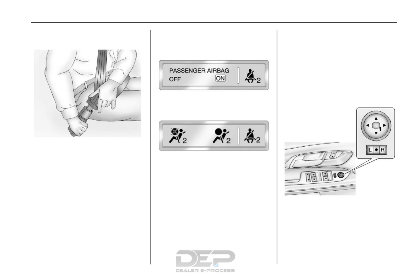
The passenger ai rbag status
indicator will be visible on the
overhead console when the vehicle
is started. See Passenger Airbag
Status Indicator 1010.
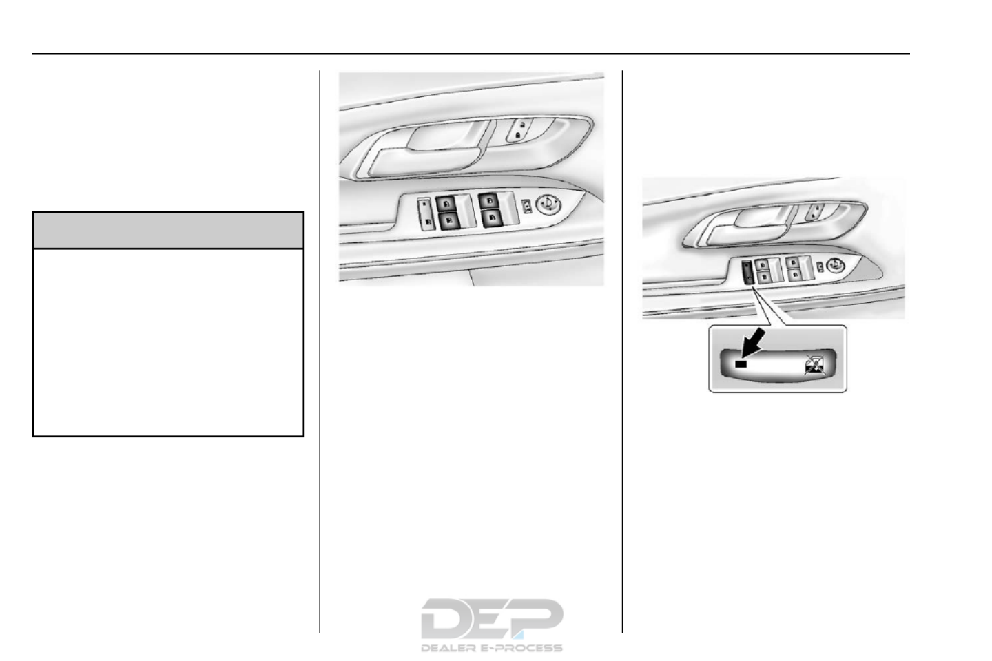
Mirror Adjustment
Exterior
To adjust the mirrors:
1. Move the selector switch to L
(Left) or R (Right) to choose
the driver or passen ger mirror.
2. Press the arrows on the control
pad to move each m irror in the
desired direct ion.

14 In Brief
3. Return the selector s witch to
the middle positi on.
See .Power Mirrors 380
Interior
Adjustment
Adjust the rearview mirro r to clearly
view the area beh ind the vehicle.
Manual Rearview Mirror
For vehicles with a manual rearview
mirror, push the tab forward for
da ytime use and pull it rearward fo r
nighttime use to avoid the glare of
the headlamps from behind. See
Manual Rearview Mirror 390.
Automatic Dimming Rearview
Mirror
Vehicles with an automatic dimming
inside rearview mirr or automatically
reduce the glare of the headlamps
from behind. The dimming feat ure
com es on when the vehicle is
started. See Automatic Dimming
Rearview Mirror 390.
Steering Wheel
Adjustment
To adjust the steering wheel:
1. Pull th e lever down.
2. Move the steering wheel up
or down.
3. Pull or push t he steering wheel
cl oser or awa y from you.
4. Pull the lever up to lock the
steering wheel in place.
Do not adjust the steering wh eel
while drivi ng.
Interior Lighting
Reading Lamps
These la mps are located on the
overhead console. These lamps
come on aut omatica lly when any
door is opened.
For manual operation, press the
button next to each lamp to turn it
on or off.
Dome Lamps
There are front and rear dome
lamps.
The dome lamp cont rols are located
in the overhead console. To change
the settings, press the following:
*:Turns the lamp off, even when
a door is open.
1:The lamps come on
automatically when a door is
opened.
+:Turns the dome lamps on.
The dome lamps can also be turned
on and off by pressi ng the buttons
next to the lamps.

In Brief 15
For more information on interior
lighting, See Instrument Panel
Illumination Control 1320.
Exterior Lighting
T he exterior lamp control is on the
turn signal lever.
O:Turn to operate the exterior
lamps.
O:Briefly turn to this position to
turn the automatic light control off or
on again.
AUTO : Turns the exterior lamps on
and off automatically d epending on
the exterior light.
;:Turns on the parking lamps
includ ing all lamps, except the
headlamps.
5:Turns on the headlamps,
togeth er with t he park ing lamps and
instrument panel lights.
See:
. Exterior Lamp Controls 1290
. Daytime Running Lamps (DRL)
0 130
. Fog Lamps 1320
Windshield Wiper/Washer
The windshield wiper/washer lever
is lo cated on the r ight side of the
steering column. With the ignition i n
ACC/ACCESSORY or ON/RUN/
START, move the windshield wiper
lever to select the wiper speed.
HI : Use for fast wipes.
LO : Use for slow wipes.
INT : Move the lever up to INT for
intermittent wipes, t hen turn the
3INT band up for more frequent
wipes or d own for less frequent
wipes.
OFF : Use to turn the wipers off.
1X : For a single wipe, briefly move
the wiper lever down. For several
wipes, hold the wiper lever down.
nLFRONT : Pull the windshield
wiper l ever toward you to spray
windsh ield washer fluid and activate
the wipers.
Rear Window Wiper/Washer
The rear wiper controls are on the
end of the windshield wiper lever.

16 In Brief
ON : Press the upper portion of the
button for continuous rear windo w
wipes.
OFF : The rear wiper turns off when
the button is returned to the middle
position.
INT : Press the lower portion of the
button to set a delay between
wipes.
a:Push the windshield wiper lever
forward to spray washer fluid on the
rear window. The lever automatically
returns to its o riginal position when
released.
See Windshield Wiper/Washer 930
and Rear Window Wiper/Washer
0 94.
Climate Controls
The ve hicle's heating, coo ling, defrosting, and ventilation can be controlled
with t hese systems.
Climate Control System
1. Fan Control
2. Air Delivery Mode Cont rols
3. Temperature Control
4. A/C (Air Conditioning)
5. Recirculation
6. Rear Window Defogger
7. Front Defros t
8. Outside Air

In Brief 17
Automatic Climate Control System
1. Fan Control
2. AUTO (Automatic Operation)
3. Air Delivery Mode Controls
4. Front Defros t
5. Recirculation
6. Temperature Control
7. A/C (Air Conditioning)
8. Driver and Passenger Heated
Seats
9. Rear Window Defogger
10. Power
See Climate Control Systems 1360
(If Equipped) or Automatic Climate
Control System 1380(If Equipped).
Transmission
Electronic Range Select
(ERS) Mode
ERS or manual mode allow s for the
selection o f the range of gear
positions. Use this mode when
drivi ng downhill or towing a trailer to
limit the t op gear and vehicle spe ed.
To use this feature:
1. Move the shif t lever to
M (Manual Mode).
2. Press the plus/minus button on
the shift lever to increase or
decrease the gear rang e
available.
See .Manual Mode 1670
Fuel Econ omy Mode
Vehicles with a 2.4L engine have a
Fuel Economy Mode. When
engaged, Fuel Economy Mode can
i mprove the vehicle's fuel economy.

18 In Brief
Press the eco (economy) button to
tur n this f eature on o r off. The eco
light in the instrument cluster will
come on when engaged, and a
Driver Information Center (DIC)
message displays. See Fuel
Economy Mode 1680.
Parking Br a k e
To set the parking brake, hold the
regular br ake pedal down, th en
push the parking brake pedal down.
If the ignition is on, the brake
system warning lig ht will come on.
See Brake System Warning Light
0 104.
To release the park ing brake, hold
the regular brake pedal down, then
push d own momentarily on th e
parking brake pedal until you fe el
the p edal release. Slowly pull your
foot up off the parking brak e pedal.
See .Parking Brake 1700
Vehicle Features
Infotainment System
See the infotainment ma nual for
information on the radio, a udio
players, phone, navigation system,
and voice or speech recognition.
It also includes information on
settings.
Steering Wheel Controls
The infotainment system can be
operated by using the steering
wheel controls . See "Steering
Wheel Contro ls" in the infotainment
manual.

In Brief 19
Cruise Control
o:Press to turn the cruise control
system on and off.
n:Press to disengage cruise
control without erasing the s et
speed from memor y.
RES/+ : If there is a set speed in
memo ry, mo ve the thumbwheel up
briefly to resume to that speed or
hold upward to accelerate. If cruis e
control is already active, use to
increase vehicle speed.
SET/ :−Move the thumbwheel down
briefly to set the speed and activat e
cruise control. If cruise control is
already active, use t o decrease
speed.
See .Cruise Control 1730
Driver Inf ormation
Center (DIC)
Th e DIC d isplay is in th e center of
the instrument cluster. It shows the
status of many vehicl e systems.
The DIC buttons are below t he
climate control s ystem.
MENU : Press this button to get to
the Trip/Fuel M enu and the Veh icle
Information Menu.
Q Ror : Use these buttons to scroll
through the items in each menu.
A small marker will mo ve along the
page as you scroll through the
items. This shows where each page
is i n the menu.
SET/CLR : Use this button to set or
clear the menu item when it is
displayed.
See Driver Information Center (DIC)
0 110.
Forward Collision Alert
(FCA) System
If equipped, FCA may h elp avo id or
reduce the harm caused by
front-end crashes. FCA pr ovides a
green indicato r, V, when a vehicle
is detected ahead. Whe n
approaching a veh icle ahead too
quickly, FCA provides a red fla shing
alert and rapidly beeps. This alert
stays lit if you follow a vehicle much
too clo sely.
See Forward Collision Alert (FCA)
System 1790.

20 In Brief
Lane Departure
Warning (LDW)
If equipped, LDW m ay help avoid
unintent ional lane departures at
speeds of 56 km/h (35 mp h) or
greater. LDW us es a camera se nsor
to detect the lane mark ings. The
LDW light, @, is green if a lane
marking is detected. I f the vehicle
depart s the lane without using a turn
signal in that direction, the li ght will
change to amber and flash. In
addition, beeps will sound.
See Lane Departure Warning (LDW)
0 183.
Side Blind Zone
Alert (SBZA)
If equipped, SBZA will detect
moving vehicles in the next lane
over in the vehicl e's side blind zone
area. Whe n this happens , the SBZA
d isplay will light up in the
corresponding outside side mirror
and will flash if the tu rn signa l is on.
See Side Blind Zone Alert (SBZA)
0 181.
Rear Vision
Camera (RVC)
If equipped, RVC displays a view of
the area behind the vehicle , on the
infotainment system display, when
the vehicle is shifted into
R (Reverse).
See Rear Vision Camera (RVC)
0 175.
Rear Cross Traffic Alert
(RCTA) System
If equipped, the RCTA system uses
a triangl e with an arrow displayed
on the RVC screen to warn of traffic
behind your vehicle that may cross
your vehicle's p ath while in
R (Reverse). In addition, beeps will
sound.
See Rear Cross Tra ffic Alert“
(RCTA) under”Rear Vision Camera
(RVC) 1750.
P a rking Assist
If equipp ed, Rear Parking Assist
(RPA) uses sensors on the rear
bumper to assist with parking and
avoiding objects while in
R (Reverse). It operates at speeds
less than 8 km/h (5 mph) and uses
audible beeps to provide distance
and system i nformation.
Keep the sen sors on the vehicle's
r ear bumper clean to e nsure proper
operation.
See .Parking Assist 1780
Power Outlets
The accessory power outlets can be
used to connect electrical
equipment, such as a ce ll phone or
MP3 player.
There are fo ur accessory p ower
outlets: inside the open storage
area in front of the shift lever, inside
the center console storage, on the
r ear of the center console storage,
and in the rear carg o compart ment.
To use the outlets, remove the cover
and close wh en not in use.
See .Power Outlets 960

In Brief 21
Universal Remote System
If equipped, these buttons are in the
overhead console. Th e system can
repl ace up to three remote con trol
transmitters used to activate
devices such as garage door
openers, se curit y systems, and
home automation devices.
Read the instructions completely
before attempting to program the
Un iversal Remote system. Because
of the steps involved, i t may be
helpful to have another person
available to ass ist w ith programming
the Uni versal Remote system.
See Universal Remote System
0 125.
Performance and
Maintenance
Traction Control /
Electronic Stability
Control
The traction control system limits
wheel spin. The system is on when
the vehicle is started .
The StabiliTrak system assists with
directional control of the vehicle in
difficult drivi ng conditions. The
system is on when the vehicle is
started.
. To turn off traction control, press
and release gon the console.
iilluminates and the
app ropriate DIC message
displays. See Ride Control
System Messages 1170.
. Press and release gagain to
turn traction control back on.
. To turn off both Traction Control
and StabiliTrak, press and hold
g guntil and iilluminate and
the appropriate DIC message
displays. See Ride Control
System Messages 1170.
.Press gagain to turn on both
systems.
See Traction Control/Electronic
Stability Control 1710.
Tire Press ure Monitor
This vehicle may have a Tire
Pressure Monitor Sys tem (TPMS).
The low tire pressure warning light
alerts to a significant loss in
pressur e of one of the vehicle's
tires. If the warning light comes on,
stop as soon as possible and inflate
the tires to the recommended
pressure shown on t he Tire and
Loading Information label. See

22 In Brief
Vehicle Load Limits 1550. The
warni ng light will remain on unt il the
tire pressure is co rrected.
The low tire pressure warni ng light
may come on in cool weath er when
the vehicle is first started, and th en
turn off as the vehicle is driv en. This
may be an early i ndicator that the
tire press ures are getting low and
the tires need to be inflated to the
proper pressure.
The TPMS does not replace no rmal
monthly tire maintenance. Main tain
the correct ti re pressures.
See Tire Pressure Monitor System
0 237.
Engine Oil Life System
The engine oil life system calculates
engine oil life based on vehicle use
and dis plays the CHA NGE ENGINE
OIL SOON message when it is time
to change the engine oil an d filter.
The oil life system sh ould be reset
to 100% only following an oil
change.
Resetting the Oil Life System
1. Turn the ignition to ON/RUN,
with the engine off.
2 . Press th e DIC MENU button to
display the Vehicle
Information menu.
3. Pre ss either the up or down
arrows to view REM AINING
OIL LI FE.
4. Press the SET/CLR button until
100% is displayed.
5. Turn the key to LOCK/OFF.
Or:
1. Turn the ignition to ON/RUN
with the engine off.
2. F ully press a nd release the
accelera tor ped al three times
within five seconds.
See .Engine Oil Life System 2060
E85 or FlexFuel
Vehicles with a yellow fuel cap can
use either unleaded gasoline or
ethanol fuel containing up to 85%
ethanol (E85). See E85 or FlexFuel
0186. For all other vehicles, use
only the unle aded gasoline
described under .Fuel 1840
Driving for Better Fuel
Economy
Driving habits can aff ect fuel
m ileage. Here are some d riving tips
to get the best fuel economy
possible.
. Avoid fast starts and accelerate
smoothly.
. Brake gradually and avoid
abrupt stops.
. Avoid idling the engine f or long
period s of time.
. When road and weather
conditions are appropriate, use
cruise con trol.
. Always follow posted speed
limits or drive more slowly when
conditions require.
. Keep veh icle tires properly
inflated.
. Co mbine several trips into a
single trip .

In Brief 23
. Replace the vehicle's tires with
the same TPC Spec number
molded into t he tire's sidewall
near the size.
. Follow recommended sched uled
maintenance.
Roadside Assistance
Program
U.S.: 1-800-243-8872
TTY Users (U.S. Only):
1-888-889-2438
Canada: 1-800-268-6800
New Chevrolet owners are
automatica lly enrolled in the
Roadside Assistance Program.
See Roadside Assistance Program
0 292.

24 Keys, Doors, and Wi ndows
Keys, Doors, and
Windows
Keys and Locks
Keys . . . . . . . . . . . . . . . . . . . . . . . . . . . 24
Remot e Keyless Ent ry (RKE)
System . . . . . . . . . . . . . . . . . . . . . . . 26
Remot e Keyless Ent ry (RKE)
System Operation . . . . . . . . . . . . 26
Remote Vehicle Start . . . . . . . . . . 28
Door Locks . . . . . . . . . . . . . . . . . . . . 29
Power Door Locks . . . . . . . . . . . . . 30
Delayed Locking . . . . . . . . . . . . . . . 30
Automatic D oor Locks . . . . . . . . . 30
Lockout Protect ion . . . . . . . . . . . . . 31
Safety Locks . . . . . . . . . . . . . . . . . . . 31
Doors
Liftgate . . . . . . . . . . . . . . . . . . . . . . . . 32
Vehicle Security
Vehicle Security . . . . . . . . . . . . . . . . 35
Vehicle Alarm System . . . . . . . . . 35
Immobilize r . . . . . . . . . . . . . . . . . . . . 36
Immobilizer Operati on . . . . . . . . . 37
Exterior Mirr ors
Convex Mirrors . . . . . . . . . . . . . . . . 37
Power Mirrors . . . . . . . . . . . . . . . . . . 38
Heated Mirrors . . . . . . . . . . . . . . . . . 38
Rever se Tilt Mirror s . . . . . . . . . . . . 38
Interior Mir rors
Interi or Rearview Mirrors . . . . . . . 39
Manual Rearview Mirror . . . . . . . . 39
Auto matic Dimming Re arview
Mirror . . . . . . . . . . . . . . . . . . . . . . . . . 39
Windows
Wind ows . . . . . . . . . . . . . . . . . . . . . . . 39
Power Windows . . . . . . . . . . . . . . . 40
Sun Visors . . . . . . . . . . . . . . . . . . . . . 41
Roof
Sunroof . . . . . . . . . . . . . . . . . . . . . . . . 41
Keys and Locks
Keys
{Warning
Leaving children in a vehicle with
th e ignition key is dangerous and
children or ot hers could be
seriously injured or killed. They
could operate the power windows
or other controls or make th e
vehicle mo ve. The windows will
function with the keys in the
ignition, and children or others
could be caught in the path of a
closing window. Do not leave
children in a vehicle with the
ignition key.

Keys, Doors, and Windows 25
{Warning
If the key is unint entio nally
rotated while the vehicle is
running, the ignition could be
m oved out of the RUN position.
Th is could be caused by hea vy
items han ging from the key ring,
o r by larg e or long items a ttached
to the key ring that cou ld be
contacted by the d river or
steering wheel. If the i gnition
moves out of the RUN position,
the e ngine will shut off, braking
and steering pow er assist may b e
(Continued)
Warning (Continued)
impacted, and airba gs may n ot
deplo y. To reduce the risk of
unintentional rotation of the
ignition key, do not change the
way the ignition key and Remote
Keyless En try (RKE) transmi tter,
i f equipped , a re connect ed to the
provided key ring s.
The ignition key, key rings, and RKE
transmitter, if equipped , are
designed to work t ogether. As a
system, it reduce s the risk of
u ninte ntionally moving the key out
of the RUN position. If repl acements
or add itions are required, see your
dea ler. Limit added items to a few
essential keys or small, l ight items
no larger than an RKE transmitter.
The key that is part of the Remote
Keyless Entry (RKE) transmitter can
be used for the ignition and all
locks.
Press the button on the RKE
transmitter to extend th e key. Press
the button and the key blade to
retract the key.
See your dealer if a new key is
needed.
If it becomes difficult to t urn the key,
inspect the key blade for debris.
Periodically clean wit h a brush
or pick.
If locked out of the vehicle, see
Roadside Assistance Program
0 292.

26 Keys, Doors, and Wi ndows
With an act ive OnStar subscription,
an OnStar Advisor may remotely
unlock the vehicle. See OnStar
Overview 3020.
Remote Keyless Entry
(RKE) System
See Radio Frequency Statement
0 298.
If there is a decrease in the RKE
operating range:
. Check the distance. The
transmitter may be t oo far fro m
the vehicle .
. Check the location. Other
vehicles or objects may be
blocking the signal.
. Check the transmitter's battery.
See Battery Replacement later“ ”
in th is section.
. If the transmitter is sti ll not
working correctly, se e your
dealer or a qualified technician
for service .
Remote Keyless Entry
(RKE) System Oper a tion
The RKE transmitter may work up to
60 m (19 7 ft) away f rom the vehicle.
Other conditions can af fect the
pe rformance of the transmitter. See
Remote Key less En try (RKE)
System 260.
With Remote Star t and Power
Liftgate Shown
The following may be available:
Q(Lock) : Press to lock all doors.
The turn signal indicators may flash
and/or the ho rn may sound on
second press to indicate lo cking.
See .Vehicle Personalization 1200
If a passenger door is open when Q
is pressed, all doors lock.
Pressing Qmay also arm the
theft-deterrent s ystem. See Vehicle
Alarm System 350.
K(Unlock) : Press to unlock the
driver door or all doors. See Vehicle
Personalization 1200. The turn
signal indicators may flash to
indicate unlocking has occurred.
See .Vehicle Personalization 1200
Pressing Kmay also disarm the
theft-deterrent s ystem. See Vehicle
Alarm System 350.
For vehicles with t he manual
liftgate, press Ktwice within
five seconds to unlock the liftgate.
Y(Remote Liftgate Release) :
If equipped with the power liftgate,
press an d hold until the liftgate
begins to move. Press again to stop
the power liftgate.
7(Vehicle Locator/Panic
Alarm) : Press and release one
time to initiate vehicle locator. The
exterior lamps flash and t he horn

Keys, Doors, and Windows 27
chirps three times. Press and hold
7for at least three seconds to
sound the panic alar m. Th e horn
so unds and the turn si gnals flash
until 7is pressed again or the key
is placed in the ignition and turned
to ON/RUN.
/(Remote Vehicle Start) :
If equipped, first press and
release Qthen immediately press
and ho ld /for at least
four seconds to st art the en gine
from outside the vehicle using the
RKE transmitter. Se e Remote
Vehicle Start 280.
The buttons on the keys are
disabled when there is a key in the
ignition.
Programming Transmitters to
the Vehicle
Only RKE transmitters programmed
to this vehicle will work. If a
transmitter is lost or stolen, a
replacement can be purchased and
programmed through you r dealer.
When the replacement trans mitter is
programmed to this vehicle, all
remaining trans mitters must a lso be
reprogrammed. Any lost or stolen
transmitters will no longer work
on ce the new transmitter is
programmed. See your dea ler to
have n ew tra nsmitters programmed.
Programming with a Recognized
Transmitter
To program a new key:
1. Insert the original, already
programm ed key in the ignition
and turn to the key to the ON/
RUN position.
2. Turn the k ey to LOCK/OFF,
an d remove the key.
3. Insert the new key to be
programmed and turn it to the
ON/RUN position within
five seconds.
The security light will turn off
once the key has been
programmed.
4. Repeat Steps 1 3 if additional–
keys are to be programmed.
If a key is lost or damaged, see your
deale r to have a new key made.
Programming without a
Recognized Transmitt er
Program a new key to the vehicl e
when a recognized key is not
available. Canadian regulations
require that owners see their dealer.
If there are no currently recognized
ke ys available, fo llow this procedure
to program the first key.
This pro cedure will take
approximat ely 30 minutes to
com plete for the first key. The
vehicle must be off and all of the
keys you wish to program must be
with you.
1. Insert the new vehicle key i nto
the ignition.
2. Turn to O N/RUN. The security
light will come on.
3. Wait 10 minutes u ntil the
security light turns off.
4 . Turn the ignition to LOCK/OF F.
5. Repe at Steps 2 4 two more–
times . After the third time, turn
to ON/RUN; the key is learned

28 Keys, Doors, and Wi ndows
and all previously known keys
will no longer work with the
vehicle.
Remaining keys can b e learned by
following the procedure in
“Programming with a Recognized
Transmitter.”
Battery Replacement
Replace th e b attery if the REPLACE
BAT TERY IN REMOTE KEY
message displays in the DIC. See
Key and Lock Messages 1160.
Caution
When replacing the battery, do
not touch any of the circuitry on
the transmitte r. St atic from your
b ody could damage the
transmitter.
The battery is not rechargeable. To
rep lace the battery:
1. Press the bu tton on the
transmitter to extend t he key.
2. Remov e the battery cover by
prying with a finger.
3. Remove the battery by push ing
on the battery and slidin g it
to ward the key blade.
4. Insert the new battery, pos itive
side facing up. Push the
battery down until it is held in
place. Replace with a CR2032
or equivalent battery.
5. Snap the battery cover back on
to the transm itter.
Remote Vehicle Start
The vehicle may have this feat ure
that allows you to start the en gine
from outside the vehicle.
/(Remote Vehicle Start) : This
butt on will be on the RKE
tran smitter if the vehicle has remote
start.
The cli mate control system will use
the previous settings during a
remote start. The rear defog may
come on during r emote start based
on cold a mbient conditions. The
rear defog i ndicator light does not
come on during remote start.
If the vehicle has heated seats, they
may come on duri ng a remote start.
See .Heated Front Seats 500
Laws in some local communities
may restrict the use of remote
starters. For example, some laws
requ ire a person using remote start
to have the vehicle in view. Check
lo cal regulations for any
requirements.
Other conditions can affect the
pe rformance of the transmitte r. See
Remote Key less En try (RKE)
System 260.
Starting the Engine Using Remote
Start
To start the engine using the remote
start feature:
1 . Press and release Qon the
RKE transm itter.
2. Immediately press and hold /
for at l east four seconds or until
the tu rn signal lamps flash. The
turn si gnal lamps flashing
confirms the r equest to remote
st art the vehicle h as been
received.

Keys, Doors, and Windows 29
The parking lamps will turn on
and remain o n a s long as the
engine is running. The
vehicle' s doors will be locked.
3. The ke y must be insert ed and
turned to ON/RUN before
driving.
The engine will shut off after
10 minutes unless a time
extension is done or the key is
inserted and turned to
ON/RUN.
Extending Engine Run Time
For a 10-minute extens ion, after
30 seconds repeat Steps 1 and 2
while the engine is still running. The
remote start can be extended once.
When the remote start is extended,
the second 10 minutes will start
immediately.
For example, if the engine has been
running for five minutes, and
10 minutes are added, the engine
w ill r un for a total of 15 minutes.
A maximum of two remote s tarts or
remote start attempts are allowed
between ignition cycles.
The vehicle's ignitio n swit ch must
be turned to ON/RUN and then back
to LOCK/OFF using the key, before
the remote start procedure can be
used again.
Canceling a Remote Start
To shut off the engine:
. Press and hold /until the
parking lamps turn off.
. Turn on the hazard warni ng
flashers.
. Insert the key an d turn it to ON/
RUN and then back to
LOCK/OFF.
Conditi ons in Which Remot e Start
Will Not Work
The remote vehicl e start feature will
not oper ate if:
. The key is in the ignition.
. The hood is not clo sed.
. The hazard warning flashers
are on.
. There is an emission control
system malfunction.
. The engine coolant temperature
is too high.
. The oil pressure i s low.
. Two remote v ehicle s tarts have
already been used.
. The vehicl e is not in P (Park).
Remote Start Ready
If the vehicle does not have the
remote vehicle start feature, it may
have the remote start ready feature.
This feat ure allows your dealer to
add the manu factu rer's re mote
vehicle start feature. See your
dealer to add the manufacturer's
remote vehicle start feature t o the
vehicle.
Door Locks
{Warning
Unlocked door s ca n b e
dangerous.
. Pas sengers, especi ally
children, can easily open
the doors and fall out of a
(Continued)

30 Keys, Doors, and Wi ndows
Warning (Continued)
moving vehicle. The chance
of being thrown out of the
vehicle in a crash is
increased if the doors are
not locked. So, all
passengers should wear
safety belts properly and the
doors should be locked
whenever the vehicle is
driven.
. Young children who get into
unlocked vehicles may be
unable to get out. A child
can be overcome by
extreme heat and can suffer
permanent injuries or even
death from heat stroke.
Always lock the vehicle
whenever leaving it.
. Outsiders can easily enter
through an unlocked door
when slowing or stopping
the vehicle. Lock the doors
to help prevent this from
happening.
To lock or unlock a door from the
outside of the vehicle, use the
Remote Keyless Entry (RKE)
transmitter. Pull the handle once
from the inside to unlock the door,
and a second time to open it.
Power Door Locks
Q:Press to lock the doors.
K:Press to unlock the doors.
Delayed Locking
This feature delays the locking of
the doors until five seconds after all
doors are closed.
When Qis pressed on the power
door lock switch while the door is
open, a chime will sound three
times indicating delayed locking is
active.
The doors will lock automatically
five seconds after all doors are
closed. If a door is reopened before
that time, the five-second timer will
reset when all doors are closed
again.
Press Qon the door lock switch
again or press Qon the RKE
transmitter to lock the doors
immediately.
This feature can also be
programmed. See Vehicle
Personalization 1200.
Automatic Door Locks
The doors will lock automatically
when all doors are closed, the
ignition is on, and the shift lever is
moved out of P (Park).
To unlock the doors:
.Press Kon a door.

Keys, Doors, and Windows 31
. Shift the transmission into
P (Park).
Automatic door unlo cking can be
programmed through the D river
Information Center (DIC). See
Vehicle Personalization 1200.
Lockout Protection
When locking is requested with the
dr iver door open a nd the key in the
ignition, all the doors will lock and
then the driver door will unlock.
This can be manually overridden by
pressing and holding Qon the
power doo r lock switch .
Safety Locks
T he rear door safety locks prevent
passengers fr om openin g the rear
doors from inside the vehicle.
Manual Safety Locks
If equipped, the safety lock is
located on the i nside e dge of the
rear doors. To use the safety lock:
1. Insert the key into t he safety
lock slot and turn it so the slot
is in the horizon tal position.
2. Close the door.
3. Do the same for the other
rear door.
To open a rear d oor when the safety
lock is on:
1. Unlock the door by activating
the inside han dle, by using the
power door lock s witch, or by
using the Remote Ke yless
Entry (RKE) transmitter.
2. Open the door from the
outside.
To cance l the safety lock:
1. Unlock the door and open it
from th e o utside.
2. Insert the key into t he safety
lock slot and turn it so the slot
is in the vertical position. Do
the same for the other door.

32 Keys, Doors, and Wi ndows
Doors
Liftgate
{Warning
Exhaust gases can enter the
vehicle if it is driven with the
liftgate or trunk/hatch open,
or with any objects that pass
through the seal between the
body and the trunk/hatch or
liftgate. Engine exhaust co ntain s
carbon monoxide (CO) which
cannot be seen or smelled. It can
cause unconsciousness and even
death.
If the vehicl e m ust be driven with
the liftgate or trunk/h atch open:
. Close a ll of the windows.
. Fully open the air outlets on
or under the instrument
panel.
. Adjust th e climate control
system to a setting that
brings in only outside air
(Continued)
Warning (Continued)
and set the fan speed to the
highes t setting. See
“ ”Climate Control Systems
in the Index.
. If t he vehicle is equipped
with a power lif tgate, disable
the power liftgate function.
See .Engine Exhaust 1650
Caution
To avoid damage to the liftgate o r
liftgat e glass, make sure th e a rea
above and behind the liftgate i s
clear before opening it.
Manual Liftgate
To un lock the lift gate, p ress the
power door lock swit ch or press K
on the Remote Keyless Entry (RKE)
transmitter twice within
five seconds. See Remote Keyless
Entry (RKE) System Operation 260.
To open the liftgat e, pres s the touch
pad u nder th e liftgate handl e and
lift up.
Use the pull cup to lower and close
the lif tgate. Do not press the touch
pad while cl osing the liftga te. This
ma y ca use the liftgate to be
unlatched.
Al ways cl ose the liftgate before
driving.

Keys, Doors, and Windows 33
Power Liftgate
{Warning
You, or others, could be injured if
caught in the path of the power
liftgat e. Make sure there is no one
in the way of the liftgate as it is
opening and closing.
If equipp ed, the power liftgate
switch i s on the overh ead console.
The vehicl e must be in P (Park ) to
operate. The taillamps flash when
the power liftgate moves.
The three modes are:
MAX : Opens to maximum height.
3/4 : Opens to a reduced height
that can be set by the vehicle
oper ator. Use this setting to pr event
the li ftgate from opening into
overhead ob structions such as a
gar age door or roof mounted cargo
during power operation. The l iftgate
can st ill be f ully opened manually.
OFF : Opens manually only.
Manual operation of a li ftgate that
also has power operation requires
more effort than a standard manual
liftgate.
To open or close the liftgate, select
MAX or 3/4 mod e and then:
. Press and hold Yon the RKE
transmitte r until the l iftgate starts
moving. See Remote Keyless
Entry (RKE) System Operation
0 26.
. Press the power liftgate b utton in
the center of t he mode switch on
the overhead console, with the
driver door unlocked.
Press and release on the8
liftgate next to the l atch to cl ose the
liftgate.
Press any liftgate button or th e
touch pad while the liftgate is
moving to stop it. Pressing ag ain
rev erses the direction. There is a
minimum distance that the power
liftgate must already be open fo r the
system to hold it o pen. If movemen t
is stopped below that m inimum, the
liftgate closes.
Do not force the liftgate o pen or
closed durin g a power cycle.

34 Keys, Doors, and Wi ndows
The power liftgate ma y be
temporarily disabled u nder extreme
temperatures or low battery
conditions. If this occurs, the liftgate
can still be operated manually.
If the vehicle is shifted out of
P (Park) while the power function is
in p rogress, the lift gate power
functio n will con tinue to completion.
If the vehicle is shifted out of
P (Park) and accelera ted before the
power liftgate latch is closed , the
liftgate may reverse to the open
positio n. Ca rgo cou ld fall out of the
vehicle. Alw ays make sure the
power l iftgat e is closed and latched
before driving away.
If the lif tgate is power opened and
th e liftgate support struts have lost
pressure, the turn signals flash and
a chime will s ound. The lift gate
stays open temporarily, and then
slowly closes. See your dealer for
service before using the liftgate.
Obstacle Detection Features
If the liftgate encounters an obstacle
during a power open or close cycle,
the liftga te will automatically reverse
direction to the full closed or open
posit ion. After removing the
obstruction, the power liftgate
operation can be used again. If the
liftgate encoun ters multip le
obstacles on the same power cycle,
the power function will deactivate
and a message will d isplay in the
Driver Information Center (DIC).
See Object Detection System
Messages 1160. After removing the
o bstructions, the li ftgate will r esume
normal power operation.
Pin ch s ensors are located on the
side e dges of the lift gate. I f an
object is caught between the liftgate
a nd the vehicle and presses again st
this sensor, the lif tgate will reverse
direction and open fully. The liftgat e
will remain open until it is activated
again or closed manually.
Setting the 3/4 Mode
To change the position the liftgate
stops at when opening:
1. Select MAX or 3/4 mode and
open the liftgate.
2. Stop the liftgate movement at
the desired height by pressing
any liftgate switch. Manually
adju st the liftgate position if
needed.
3 . Press and hold 8on the
liftgate next to the latch until
the turn signals flash and a
beep sounds t o indicate t hat
the new se tting is recorded.
When power opened wi th the 3/4
mode selected, the liftgate stops at
the new set position.
If there is no a udible and visual
feedback when setting the
intermediate stop position, the
liftgate height is being set be low the
3/4 open height minimum
(approximately 1.5 m or 5 ft). The
liftgate cannot be set below that
minimum and the new setting will
not be record ed.

Keys, Doors, and Windows 35
Manual Operat io n of Power
Liftgate
To change the liftgate to manual
operation, turn the mode switch to
the O FF position.
With the power li ftgate disabled and
all of the doors unlocked, the liftga te
can be manually opened and
closed. Manual operation of a
liftgate th at also has power
operation req uires more effort than
a standard manual liftgate.
Caution
Do not use to o much force when
closing the liftgate to avoid
damage.
To o pen the liftgate, press the touch
pad on the han dle on the outside of
the liftgate, and lift t he gate open. To
close the liftgate, use the pull cup to
lower the liftgate a nd close. With the
power liftgate d isabled, the liftgate
el ectri c latch will still power latch
once contact is made with the
striker. Always close the liftgate
before driving.
If Yon the RKE transmitter is
pressed while power operation is
disabled, the turn signals flash and
t he liftgate will not move.
The liftgate has an electric latch.
If the battery is disconnected or has
low voltage, the liftgate will not
open. The liftgate will resume
operation when the battery is
reconne cted and charged.
Vehicle Security
This ve hicle has theft-deterrent
features; however, they do not make
the ve hicle impossible to steal.
Vehicle Alarm System
This vehicle has an anti-theft alarm
system.
The ind icator light, on the
instrument panel ne ar the
windshield, indicates the status of
the system:
Off : Alarm system is disarmed.

36 Keys, Doors, and Wi ndows
On Solid : Vehicle is secured
during the delay to arm the system.
Fast Flash : Vehicle is unsecured.
A doo r, the hood, or the liftgate
is open.
Slow Flash : Alarm system is
armed.
Arming the Alarm System
1. Turn off the vehicl e.
2. Lock the v ehicle in one of
three ways:
. Use the RKE tran smitter.
. With a door open, press the
interior Q.
3. After 30 seconds the alarm
system will arm, and the
indicat or light will be gin to
slowly flash indicating the
alarm system is operating.
Pressing Qon the RKE
transmitter a second time will
bypa ss the 30-second delay
and immediately arm the alarm
system.
The vehicl e a larm syst em will not
arm if the doors a re locked with
the key.
If the driver door is opened w ithou t
first unlocking with the RKE
transmitter, the horn will chirp and
the lights will flash to indicate
pre-alarm. If the vehicle is not
started, or the door is not unlocked
by pressing Kon the RKE
transmitter during the 10-second
pre-alarm, the alarm will be
activated.
If a door , the hood, or the liftgate is
opened without first disarming the
system, t he turn signals will flash
and the horn will sound for about
30 s econds. The alarm system will
then re-arm to m onito r for the next
unauthorize d event.
Disarming the Alarm System
To disarm the alarm system or turn
off the alarm if it has been activate d:
.Press Kon the RKE transmitter.
. Start the vehicle.
To avoid setting off the a larm by
accident:
. L ock the vehicle af ter all
occupants have left the vehicle
and all doors are closed.
. Alw ays unlock a door with the
RKE transm itter.
Unlocking the driver door with the
key will not disarm the system or
turn off the alarm.
How to Detect a Tamper
Condition
If is pressed on the RKEK
transmitter and the horn chirps and
the lights f lash three times, an a larm
occurred previously while the al arm
system was armed.
If the alarm has been activated, a
message will appear on the DIC.
See Security Messages 1180.
Immobilizer
See Radio Frequency Statement
0 298.

Keys, Doors, and Windows 37
Immobilizer Operation
This vehicle has a passive
theft-deterrent system.
The system does not have to be
manu ally armed or disarmed.
The vehicle is automatically
immo bilized when the key is
removed from t he ignitio n.
The system is automatically
disarmed whe n the vehicle is
started with the correct key. The key
uses a transponder that matches an
immobilizer co ntrol unit in the
vehicle and a utomatically disarms
the system. Only an authorized key
starts the vehicl e. The vehicle may
not start if th e key is damaged.
The security light in the instrument
cluster comes on if there is a
problem with arming or disarming
the theft-deterrent system.
When trying to star t the vehicle, the
security light comes on brie fly when
the ignition is turned o n.
If the engine does not start and the
se curit y light stays on, there is a
problem with the system. T urn the
ignition off and try again.
If the engine still does not s tart, and
the key appears to be undamaged
or the light continu es to stay on, try
another ignition key. If the engine
d oes not st art with the other key, the
vehicle needs service. If the vehicle
does start, the first key may be
damaged. See your dealer who can
service the theft-deterrent system
and have a new key made.
Do not leave the key or d evice that
disarms or deactivates the
theft-deterren t system in the vehicle.
Exterior Mirrors
Convex Mirrors
{Warning
A convex mirror can mak e things,
like other veh icles, look fart her
away than th ey really are. If you
cut too sharply into the right lane,
you co uld hit a vehicle on the
right. Check the inside mirror or
glance over your sh oulder before
changing lanes.
The passenger side mirror is convex
shaped. A convex m irror's surface is
curved so more can be seen from
the driver seat.

38 Keys, Doors, and Wi ndows
Power Mirrors
To adjust the mirrors:
1. Move the selecto r switch to L
(Left) or R (Right) to choose
the driver or passenger mirror.
2. Press the arrows on the control
pad to move each mirror in th e
desired direct ion.
3. Return the selector switch to
the middle position.
Heated Mirrors
For vehicles with heated mirrors:
The heated outside rearview mirrors
turn on when the rear window
defogger is on and help to clear fog
or frost from the surface of the
mirrors.
1(Rear Window Defogger) :
Th is button is on the climate control
panel.
See Rear Window Defogger under“ ”
Automatic Climate Control System
0138 for more information.
Reverse Tilt Mirrors
If equipped with memory seats, the
passenger and/or driver mirror tilts
to a preselected position when the
vehicle is in R (Reverse). This
allows the curb to be seen when
parallel parking.
The mirror(s) return to the original
position when:
. The vehicle is shifted out of
R (Reverse), or remains in
R (Reverse ) for ab out
30 seconds.
. The ignition is turned off.
. The veh icle is driven in
R (Reve rse) ab ove a set sp eed.
To turn this feature on or off, see
Vehicle Personalization 1200.

Keys, Doors, and Windows 39
Interior Mirrors
Interior Rearview Mirrors
Adjust the rearview mirror for a clear
view of the area behind your
vehicle.
If equipped with OnStar, there are
t hree bu ttons at the bottom of t he
mirror. See your dealer for mo re
information on the system and how
to subscribe to OnStar. See OnStar
Overview 3020.
To avoid accidental OnStar calls,
clean the mirro r with the ignition off.
Do not sp ray glas s cleaner directly
on th e mirror. Use a soft towel
dampened with water.
Manual Rearv i ew Mirror
Push the tab forward for day time
use and pull it rearward for
nighttime use to avoid glare of the
headlam ps from behind.
Automatic Dimming
Rearview Mirror
If equipped, automatic di mming
reduces the glare of headlamps
f rom behind. The dimming feature
comes on when the vehicle is
started.
Windows
{Warning
Never leave a child, a helpless
adu lt, or a pet alone in a vehicle,
especially with the windows
closed in warm or hot weather.
They can be overcome by the
extrem e heat and suffer
permanent injuries or even death
f rom heat stroke.
The vehicle aerodynamics are
designed to improve fuel economy
perf ormance. This may result in a
40 Keys, Doors, and Wi ndows
pulsing sound when e ither rear
window is down and the front
windows are up. To reduce the
sound, open either a fr ont win dow
o r the sunroo f, if equipped.
Power Windows
{Warning
Children cou ld be seriously
injured or killed if caught in the
pat h of a closing window. Never
leave keys in a vehicle with
children. When there are children
in the rear se at, use the window
lockout butt on to prevent
operat ion of the windows. S ee
Keys 240.
The power windo ws work when the
ignition is in ON/RUN or ACC/
ACCESSORY, or in Retained
Accessory Power (RAP). See
Retaine d Accessory Power (RAP)
0 162.
Press the front of the switch to open
t he window. Pull the switch up to
close it.
Express Down Windows
Windows that have the
e xpress-down feature allow the
win dows to be lowered without
hol ding the switch. P ress the
win dow switch fu lly and release it to
activate the express-down feature.
The express mode can be cance led
at any time by briefly pressing,
or pulling the switch.
Window Lockout
This feature prevents the rear
passenger windows f rom operating,
except from the driver position.
Press vto activate the rear
window lockout switch. The
indicator light comes on when
activated.
Press vagain to deactivate the
lockout switch.

Keys, Doors, and Windows 41
Sun Visors
Pull the sun visor down to block
glare. Detach the sun visor from the
center mount to p ivot to the side
window or, if equipped, extend
along the rod.
Roof
Sunroof
If equipped, the sunroof switches
are on the headliner ab ove the
rearview mirror. The ignition must be
in ON/RUN or ACC/ACCESSORY,
or in Retained Accessory Power
(RA P) to operate the sunroof. See
Ignition Positions 1590and
Retaine d Accessory Power (RAP)
0 162.
. Press and hold the front or rear
of the driver side swit ch to open
or close the sunroof. The
sunshade automatically opens
with the sunroof, but must be
closed manually.
. Press and ho ld the rea r of the
passenger side switch to vent
the sunroof . Press and hold the
front of the s witch to close.
Express-open/Express-close
Press and release the front or rear
of the drive r side switch to
express-o pen or express-close the
sunroof.
Anti-Pinch Feature
If a n o bject is i n the path of the
sunroof wh en it is closing, the
anti-pinch feature detects the object
and stops the sunroof from closing
at the point of the obstruction. The
sunroof then returns to the full-open
position.

42 Keys, Doors, and Wi ndows
Dirt and debris may collect on the
sunroof seal or in the t rack. This
could cause an issue with sunroof
operation or noise. It could also plug
the water drainage system.
Periodically open the s unro of and
remove any obstacles or loose
debris. Wi pe the sunroof seal and
roof sealing area using a clean
cloth, mild soap, and water. Do not
remove grease from the sunroof.

Seats and Restraints 43
Seats and
Restraints
Head Restraints
Head Restrai nts . . . . . . . . . . . . . . . 44
Front Seats
Seat Ad justment . . . . . . . . . . . . . . . 45
Power Seat Adjustment . . . . . . . . 45
Lumbar Adjustment . . . . . . . . . . . . 46
Reclining Seatbacks . . . . . . . . . . . 47
Memory Seats . . . . . . . . . . . . . . . . . 48
Heated Front Sea ts . . . . . . . . . . . . 50
Rear Seats
Rear Seats . . . . . . . . . . . . . . . . . . . . 51
Safety Belts
Safety Belts . . . . . . . . . . . . . . . . . . . . 52
How to Wear Safety Be lts
Pro perly . . . . . . . . . . . . . . . . . . . . . . 53
Lap-Shoulder Belt . . . . . . . . . . . . . 54
Safety Belt Use During
Pregn ancy . . . . . . . . . . . . . . . . . . . . 58
Safety Belt Extender . . . . . . . . . . . 58
Safety System Check . . . . . . . . . . 58
Sa fety Belt Care . . . . . . . . . . . . . . . 58
Replacing Safety Belt System
Parts after a Crash . . . . . . . . . . . 59
Airbag System
A irbag System . . . . . . . . . . . . . . . . . 59
Where Are the Airbags? . . . . . . . 61
When Should an Airbag
Infl ate? . . . . . . . . . . . . . . . . . . . . . . . 62
What Makes an Airbag
Infl ate? . . . . . . . . . . . . . . . . . . . . . . . 63
How Does an Airbag
Re strain? . . . . . . . . . . . . . . . . . . . . . 63
What Will You See af ter an
Airbag Inflates? . . . . . . . . . . . . . . 64
Passenger Sensing System . . . 65
Servicing the Airbag - Equipped
Vehicl e . . . . . . . . . . . . . . . . . . . . . . . 69
Adding Equipme nt to the
Airbag-Equipped Vehicle . . . . . 69
Airbag System Check . . . . . . . . . . 70
Replacing Airbag System Parts
af ter a Crash . . . . . . . . . . . . . . . . . 70
Child Restraints
Older Childr en . . . . . . . . . . . . . . . . . 71
Infan ts and Young Children . . . . 72
Child Re straint Systems . . . . . . . 75
Where to Put the Restraint . . . . . 76
Lower Anchors a nd Tethers for
Childre n (LATCH System) . . . . 77
Replacing LATCH System Parts
A fter a Crash . . . . . . . . . . . . . . . . . 83
Securing Child Restraints
(Rear Seat) . . . . . . . . . . . . . . . . . . . 83
Securing Child Restraints (Front
Passenger Seat) . . . . . . . . . . . . . 86

44 S eats and Restraints
Head Restraints
Front Seats
Th e vehicle's front seats have head
restraints in the outboard seating
positions.
{Warning
With head restraints that are not
in stalled and adjusted properly,
there is a greater chance that
occup ants will suffer a neck/
spinal injury in a cra sh. Do not
driv e until the head restraints for
all occupants are i nstalled and
adjuste d prope rly.
Adjust the h ead restraint so that the
top of the restraint is at the same
height as the top o f the occupant's
head. T his position r educes the
ch ance of a neck injury in a crash.
The heigh t of the he ad rest raint can
be adjusted. Pull the head restraint
up to rais e it. Try to move the head
r estraint to make sure tha t it is
locked in pla ce.
To lo wer the h ead restraint, press
the button, located on the top of the
seatback, and push the head
restraint d own. Try to move the
h ead restraint after the button is
released to make sure tha t it is
locked in pla ce.
The front seat outboard head
restr aints are not removable.

Seats and Restraints 45
Rear Seats
The vehicle's rear seat has head
restraints in the outboard seating
positions that can not be adjusted.
Rear outboard he ad restraints are
not removable.
Front Seats
Seat Adjustment
{Warning
You can lose control of the
ve hicle if you try to adju st a d river
seat while the vehicle is moving.
Adjust the driver seat only when
the vehicle is not moving.
To adjust a manual seat:
1. Pull the handle at the front of
the seat cushion.
2. Move the seat forward or
rearward to adjust the seat
position.
3. Release the handle to stop the
seat from moving.
4. Try to move the seat back and
forth to be sure it i s locked in
place.
Power Seat Adjus tment
Four-Way Power Seat
1. Seat Position Handle
2. Height Adjustment Control

46 S eats and Restraints
To adjust a power seat, if equ ipped :
. Mov e the seat forward or
rearward using the handle under
the fron t of th e seat cushion (1).
See .Seat Adjustment 450
. Raise or lower the entire seat by
moving the control (2) up
or down.
To adjust the seatback, see
Reclining Seatbacks 470.
To adjust the lumbar s upport, see
Lumbar Adjustment 460.
Eight-Way Power Seat
To adjust a power seat, if equ ipped :
. Mov e the seat forward or
rearward by sliding the control
forward or rearward.
. Raise or lower the front part of
the seat cushion by moving the
front of the control up or down.
. Raise or lower the entire seat by
moving the r ear of the control up
or down.
To adjust the seatback, see
Reclining Seatbacks 470.
To adjust the lumbar s upport, see
Lumbar Adjustment 460.
Lumbar Adjustment
Power Lumbar
Eight-Way P ower Seat Shown,
Four-Way Similar
If available, press and hold the fro nt
or rear of the switch to increase or
decrease lumbar support. Re lease
the switch when the seatback
reaches the desired level of lumbar
support.

Seats and Restraints 47
Reclining Seatbacks
{Warning
Sitting in a reclined position wh en
the vehicle is in motion can be
dangerous. Even when buckled
up, the safety belts can not do
their job.
The shoulder belt will not be
against your body. I nstead, it will
be in front of you. In a crash, you
coul d go into it, receiving neck or
other i njuries.
The lap belt could go up over
your abdomen. The belt forces
would be th ere, not at your pelvic
bones. This could cause serious
internal injuries.
For proper protection whe n the
vehicle is in motion, have the
seatback upright. Then sit well
back in the seat and wear the
sa fety belt properly.
Do not have a seatback reclined if
the vehicle is moving.
Manual Reclining Seatbacks
{Warning
If either se atback is not locked, it
could move forward in a sudden
stop or crash. That could cause
injur y to t he pers on sitting there.
Always push and pull on the
seatbacks to be sure they are
locked.
To recline a manual seatback:
1. Lift the lever.
2. Move the s eatback to the
desired position, and t hen
release the lever to lock the
seatback in place.
3. Push and pull on the seatback
to make sure it is locked.
To ret urn the seatback t o the upri ght
position:
1. Lift the lever fully without
applying pressure to the
seatback, and the seatback will
return to the upright position.

48 S eats and Restraints
2. Push and pull on the seatback
to make sure it i s locked .
Power Reclining Seatbacks
To adj ust a power seatb ack,
if available:
. Tilt the top of the control
rearwar d to recline.
. Tilt the top of the control forward
to raise.
Memory Seats
If available, the 1, 2. and MEM
(Memory) buttons on the ou tboard
si de of the driver seat are use d to
manually save and r ecall the driver
se at and outside mirror positions.
These manually stored positions are
referred to as Button Memory
positions.
The ve hicle will also automatically
s ave driver seat and outside mirror
positions to the current driver
Remot e Keyless Ent ry (RKE)
trans mitter when the ignition is
turned off. These automatically
stored positions are referred t o as
RKE Memory positions. See
Remote Key less En try (RKE)
System Operation 260.
Storing Button Memory Positions
To save posit ions into Button
Memory:
1. A djust the driver seat, seat back
recliner, an d b oth outside
mirrors to the d esired driving
positions.
2. Press and hold MEM (Memory)
and 1 at th e same time until a
beep sounds.
3. Repeat Step s 1 and 2 for a
second d river using 2.
Recalling Butto n Memory
Positions
To recall the Button Memory
positions, press a nd h old 1 or 2. The
drive r sea t and o utside mirrors
mov e to the p ositions stored to
those buttons when pressed.
Releasing 1 or 2 b efore the stored
positions ar e reached stops the
recall.

Seats and Restraints 49
If something has blocked the driver
seat whi le recalling a memory
position, the r ecall may stop.
Remove t he obstruction; then press
and hold the appr opriate manual
control for the memory item that is
not r ecalling for two seconds. Try
recalli ng the memory position again
by pressing the appropriate memory
button. If the memory position is still
no t recalling, see your dealer for
service.
Recalling RKE Memory Positions
(Memory Remote R ecall)
The Memory Remote Recall feature
can recall the d river seat and
outside mirrors to previously stored
RKE Memory positions when
entering the vehicle.
Every time the ignition is turned off,
the positions of the driver seat and
outside mirro rs are automatically
stored to th e RKE transmitter that
was used to start the vehicle. These
positions are called RKE Memory
positions and may be differen t than
the previously m entioned Button
Memory positions saved to the
1 or 2 buttons. To recall RKE
Memory positions, unlock the d river
doo r with the RKE transmitter and
open the driver door. If the driv er
door is al read y open, p ressing the
RKE transm itter Kbutton will also
activate the RKE Memory recall.
The driver seat and outsi de mirrors
will move to t he previously saved
RKE Memory positions.
This feature is turned on or off using
the vehicle personalization menu.
See .Vehicle Personalization 1200
To stop recall movement, press any
of the me mory, power mirror,
or power seat controls.
If something has blocked the driver
seat whi le recalling a memory
position, the r ecall may stop.
Remove t he obstruction; then press
and hold the appr opriate manual
control for the memory item that is
not r ecalling for two seconds. Try
recalli ng the memory position again
by opening the driver door and
pressing Kon the RKE transmitter.
RKE transmitters are not labeled
wit h a number. If you r memory se at
position is stored to 1 or 2 but this
position is not automatically
recalling, then store your positions
to the other button or switch RK E
transmitters with the other dr iver.
If the memory position is still not
r ecalling, see your dealer for
service.
Easy Exit Driver Seat
This featur e moves th e seat
rearward allowing the driver more
room to exit the vehicle.
To activate, turn the ignition off and
open the driver door. If the driv er
door is already open, t urning the
ignition off will activate the recall.
This feature can be turned on or off
using the vehicle pers onalization
menu. See Vehicle Personalization
0 120.
To stop recall movement, press one
of the memory or power seat
controls.
If something has blocked the driver
seat while recalling the exit pos ition,
the recal l may stop. Remove the
obstruction ; then press and hold the
power seat control rearward for

50 S eats and Restraints
t wo seconds. Try recalling the exit
position again. If the exit position is
stil l not recalling, see your dea ler for
service.
Heated Front Seats
{Warning
If you cannot feel temperature
chan ge or pain to the skin, the
seat hea ter may cause burns. To
reduce the risk of burns , people
with such a condition should use
care when using the seat heater,
especially for long peri ods of
time. Do not place anything on
the seat that insulates again st
heat, su ch as a blanket, cushi on,
cover, or sim ilar item. This may
cause the seat heater to
overheat. An ove rheated seat
heater may cause a burn or may
damage the seat.
Uplevel Climate Control System
Shown, Base Similar
If available, the buttons are near the
climate controls. To operate, the
ignit ion must be in ON/RUN.
Press z Jor to heat the driver or
passenger seat cushion and
seatback.
Press the button once for the
highest setting. W ith each press of
the button, the heated seat will
chan ge to the next lower setting,
a nd then the off setting. Thr ee lights
in dicate the highest setting, and one
light indicates the lowest.
The passenger seat may take
l onger to heat up.
Remote Start Heated Seats
When it is cold outside, the heated
seats can be prog ramme d to turn on
au tomatically during a rem ote
vehicle start. The heated seats will
be canceled when the ignition is
turned on. Press the heated seat
button to use the heated seats after
the vehicle is started.
The heated seat button lights will
not turn on during a remote start.
The temperature of an unoccupied
seat may be reduced.
To program the heated seat feat ure
to enable d, see Vehicle
Personalization 1200.

Seats and Restraints 51
Rear Seats
Split F olding Seatbacks
Ei ther side of the rear seatback can
be folded down for more cargo
space.
Folding the Seatback s
Caution
Folding a rear seat with the safety
belts still fastened may cause
damag e to the seat or the safety
belt s. Always unbuckle the safety
belts and return them to th eir
normal stowed position be fore
folding a rear seat.
To fold the seatback down:
1. Unbuckle the rear safety belts
and place the fr ont seatbacks
in the upright position. See
Reclining Seatbacks 470.
2. Lift the lever on the top of the
seatback.
3. Fold the seatback forward.
K eep the seatback in the upright,
locked po sition when not in use.
Raising the Seat backs
{Warning
If either s eatback is not locke d, it
could m ove forward in a sudden
stop or crash. That could cause
injury to the person s itting there.
(Continued)
Warning (Continued)
Always push and pul l on t he
seatbacks to be sure they are
locked.
{Warning
A safet y belt that i s impr operly
routed, not properly attached,
or twisted will not prov ide the
protection needed in a crash. The
person wearing the belt could be
seriously injured. After raising the
rear seatback, always check t o be
sure that the safety belts are
properly routed and attached, and
are not twisted.
To raise the seatback:
1. Lift the lever on top of the
seatback. Raise the seatback
and release the lever.
2. Push the seatback rearward
until it locks in the upri ght
position.

52 S eats and Restraints
3. Make sure the rear sa fety belts
are not twisted or caug ht
bet ween the seat cushion and
the seatback.
Reclining the Seatbacks
To recline the seatback:
1. Lif t and hold the lever o n top of
the seatback.
2. Tilt the seatback rearward, then
release the lever when the
seatback is in t he desired
position.
Seat Adjustment
To slide the entire seat forward or
rearward:
1. Lift a nd hold the release bar
under the front o f the seat
cushion to unlock the seat.
2. Slide the seat to the desired
position.
3. Release the ba r.
4. Try to move t he seat back and
forth to ensure the seat is
locked i nto place.
Saf ety B elts
This section of the manual
des cribe s how to us e safety belts
properly. It also describes some
things not to do with safety belts.
{Warning
Do not let any one ride where a
safety belt cannot be worn
properly. In a crash, if you or your
passenger(s) are not wearing
safety belts, injuries can be much
worse than if you are wearing
safety belts. You can be seriously
injured or killed by hitting things
inside the vehicle harder or by
being eject ed from t he vehicle. In
addition, anyone who is not
buckled u p can strike other
passengers in the vehicle.
It is extremely dangerous to ride
in a cargo area, inside or outside
of a vehicle. In a collision,
passengers riding in these areas
are more likely to be seriously
injured or killed. Do not allow
(Continued)
Warning (Continued)
passengers to ride in any area of
the veh icle that is not equipped
with seat s and safety belts.
Always wear a safety belt, and
check that all passenger(s ) are
restrained properly too.
This vehicle has indicators as a
reminder to buckle the safety belts.
See .Safety Belt Reminders 1000
Why Safety Belts Work

Seats and Restraints 53
When riding in a vehicle, you travel
as fast as the vehicle does. If the
vehicle stops suddenly, you ke ep
going until something stops y ou.
It could be the windshield, the
instrument panel, or the safety belts!
W hen you wear a safety belt, you
and the vehicle slow down toge ther.
There is more t ime to stop because
you stop over a longer distance and,
when worn properly, your strongest
bones take the forces from the
safety belts. That is why wearing
safety belts makes such good
sense.
Questions and Answers About
Safety Belts
Q: Will I be trapped in the vehicle
after a cr ash if I am wearing a
safety belt?
A: You be whether you arecould —
wearing a safety belt or not.
Your chance of being conscious
during and after a crash, so you
can unbuckle and get out, is
much greater if you are belted.
Q : If my vehicle has airbags, why
should I have to wear safety
belts?
A: Airbags are supplemental
s ystems only; so they work with
safety belts n ot instead of—
them. Whether or not an airb ag
is provided, all occupants still
have t o buckle up to get the
most protection.
Also, in nearly a ll states and in
all Canadian provinces, th e law
requi res wearing sa fety belts.
How to Wear Safety Belts
Properly
T his sect ion is only for people of
adult size.
There are special things t o know
about safety b elts an d children. And
there are different rules for smaller
childr en and infants. If a child will be
riding in the vehicle, see Older
Children 71 Infants and Young0or
Children 720. Follow those rules for
eve ryone's protection.
It is v ery important fo r all occupants
to bu ckle up. Statistics show that
unbelted people are hurt more often
in crashes than those who are
wearing safety belts.
There are important things to know
about wearing a safety belt properly.
. Sit up straight and always keep
your feet on the floor in f ront
of you.
. Always use the correct buckle
for your seating positi on.
. Wear the lap part o f the belt low
and snug on the hips, just
touch ing the thighs. In a crash,
this applies force to the strong

54 S eats and Restraints
pelvic bones and you would be
le ss likely to slide under the lap
belt. If you slid under it, t he belt
would ap ply f orce on your
abdomen. This could cause
serious or even fatal injuries.
. Wear the shoulder belt over the
shoulde r and across the che st.
These parts of the body are best
abl e to take belt rest raining
forces. The shoulder belt locks if
there is a sudden stop or crash.
{Warning
You can be seriously injured,
or even killed, by not wearing
your safety belt properly.
. Never allow the lap or
shoulder bel t to become
loose or twisted.
. Never wear the shoulder
belt under both arms or
behind your back .
. Never route the lap or
sh oulder belt over an
armrest.
Lap-Shoulder Belt
All seating pos itions in the vehicle
have a lap-shoulder belt.
The followi ng instructions explain
how to wear a lap-shoulder belt
properly.
1. Adjust the seat, if the seat is
adjustable, so y ou can sit up
straight. To see how, see
“ ”Seats in the Index.
2. Pick up the latch plate and pull
the bel t across you. Do not let
it get tw isted.
The lap-shoulder belt may lock
if you pull the belt across you
very quickly. If this happens, let
the be lt go back slightly to
unlock it. Then pull the belt
across you more slowl y.
If the sh oulder portion of a
passenger b elt is pulled out all
the way, the child restra int
locking feature may be
engaged. If this happens, let
the b elt go back all the way
and start again.
If the webbing locks in the latch
plate before it reache s the
buckle, tilt the latch plate flat to
unlock.

Seats and Restraints 55
3. Push the latch plate into the
buckle until it clicks.
Pull up on the latch p late to
make sure it is s ecure. If the
belt is not long e nough, see
Safety Belt Extender 580.
P osition the release button on
the buckle s o that the safety
belt could be quickly unbuckled
if necessary.
4. If equipped with a should er belt
height adjuster, move it to the
height that is right for you. See
“ ”Shoulder Belt Height Adjuster
later in this sectio n for
instructions on use and
important safety informat ion.
5. To make the lap part tight, pull
up on the shoulder belt.
To unlatch the belt, push the button
on the bu ckle.
Alway s stow the saf ety belt slowly.
If the safety bel t webbi ng returns
quickly to the stowed p osition, the
r etractor may lock and ca nnot be
pulled out. If this happens, pull the
safety belt straight out firmly to
unlock the webbing, and then
release it. If the webbing is still
locked in the retractor, see your
dealer.
Before a do or is closed, be sure the
s afety belt is out of the w ay. If a
door is slammed a gainst a safety
belt, damage can o ccur to both the
safety belt and the vehicle.
Shoulder Belt Height Adjuster
T he vehicle has a shoulder belt
he ight adjuster f or the driver and
front outboard passenger seating
positions.
Adjust the height so the shoulder
portion of the belt is on the shoulder
and not falling off of it. The belt
should be close to, but not
contacting, the neck. I mproper
shoulder belt h eight adjustment
could reduce the effectiveness of
the safety belt in a crash. See How
to Wear Safety Belts Properly 530.

56 S eats and Restraints
Move the height adjuster up to the
desired position by pushing up on
the height a djuster.
After the height adjuster is set to the
desired position , try to move it down
without pressing the release button
to mak e sure it has locked into
posit ion. Pr ess the release button to
lowe r the height adjuster.
Safety Belt Pretensioners
This vehicle has safety b elt
pretensioners f or front outboard
o ccupants . Although the safety belt
pretensioners cann ot be seen, they
are part of the safety belt assembly.
They can help tighten the safety
belts during the e arly stages of a
mod erate to severe frontal, near
frontal, or rear crash if the thres hold
conditions for pretensioner
act ivation are met. Safety belt
pretensioners can also help tigh ten
the safety belts i n a side crash or a
rollover event.
Pretensioners work only once. If the
pretensioners are activated in a
crash, the preten sioners and
possibly other parts of the safety
belt syst em will need to be replaced.
See Replacing Safety Belt System
Parts after a Crash 590.
Rear Safety Belt Comfort
Guides
{Warning
A safety belt that is not properly
worn may not provide the
protection needed in a crash. The
person wearing the b elt could be
seriously injured. The should er
belt should go over the shoulder
and across the chest. These parts
of the body a re best able to take
belt restraining forces.
Rear safety belt comfort guides may
provide added safe ty belt comfort
for older children who have
outgrown booster seats and for
some a dults. When installed on a
shoulder belt, the comfort guide
positions the shoulder belt away
from the ne ck and head.
This vehicle has rear safety belt
comfort guides in the rear outboard
seating positions.

Seats and Restraints 57
To install:
1. Remove the guide from its
storage po cket on the side of
the seatback.
2. Place t he guide over the belt,
and insert the two edges of the
belt into the slots of the guide.
3. Be s ure tha t the belt is no t
twisted and it l ies flat. The
elastic cord must be behind the
belt with the plastic guide on
the front.
4. Buckle, position, and release
the safety belt as described
prev iously in this section. Make
sure the shoulder portion of the
belt is on the shoulder and no t
falling off of it. T he belt should
be close t o, but not co ntacting,
the neck.
To remove and store the comfort
guide, squeeze the belt edges
together so that the safety belt can
be removed from the guide. Slide

58 S eats and Restraints
the guide back into its storage
pocket located on th e side of the
seatback.
Safety Belt Use During
Pregnancy
Safet y belts work for everyone,
including pregnant wo men. Like all
occupants, they are more likely to
be seriously injured if they do not
wear safety belts.
A pregnant woman should wear a
la p-shoulder belt, and the lap
portion should be worn as low as
possi ble, below the rounding,
throughout the pre gnancy.
The best way to pr otect the fetus is
to pr otect the mother. When a safety
bel t is worn p rope rly, it is more likely
that the fetus wi ll not be hurt in a
crash. For pregnant women, as for
anyone, the key to making safety
belt s effective is wearing them
properly.
Safety Belt Extender
If the vehicle's safety belt will fasten
around you, you should use it.
But if a safety belt is not long
enough, your dealer will order you
an extender. When you go in to
order it, take the heaviest coat you
will wear, so the extend er will be
long enough for you. To help avoid
personal injury, do not let someone
else use it, and use it only for the
seat it is m ade to fit. The extender
has been designed for adults. Never
use it for securing child seats. To
wear it, attach it to the regular safe ty
belt. For more information, see the
instructi on sheet that comes with
the extender.
Safety System Check
Now and then, check that the safety
belt reminder light, safety belts,
buckles, latch plates, retractors, and
anchorages are all working properly.
Look fo r any other loose or
dam aged safety belt system parts
that might keep a safet y belt system
from doing it s job. See your dealer
to have it repai red. Torn or fraye d
safety belts may not protect you in a
crash. They can rip apart under
impact forces. If a belt is torn or
frayed, get a new one right away.
Make sure the safety belt reminder
light is working. See Safety Belt
Reminders 1000.
Keep s afety belts clean and dry.
See .Safety Belt Care 580
Safety Belt Care
Keep belts clean and dry.

Seats and Restraints 59
{Warning
Do not bleach or dye safety belts.
It may severely weak en them. In
a crash, they might not be able to
provide adequate protection.
Clean safety belts only with mild
soap and lukewarm water.
Replacing Safety Belt
System Parts after a
Crash
{Warning
A crash can damage the s afety
belt system in the vehicle.
A damaged safety belt system
may not properly protect the
pe rson using it, resulting in
serious injury or even death in a
crash. To help m ake sure the
safety belt systems are working
properly after a crash, have them
inspected and any necessary
replacements made as soon as
possible.
After a minor crash, replacement of
safety belts may not be nece ssary.
But the safety bel t assemblies t hat
were used during any crash may
have been stressed or damaged.
See your dealer to have the safet y
belt assemblies inspected or
replaced.
New parts and repairs may be
necessary even if t he safety belt
system was n ot being used at t he
time of the crash.
Have the safety belt pretensioners
checked if the vehicle has been in a
cras h, or if t he airb ag readiness light
stays on after you start the vehicle
or whil e you are driv ing. See Airbag
Readiness Light 1010.
Airbag System
The ve hicle has the following
airbags:
. A frontal airbag for the driver.
. A frontal airbag for the front
outboard passenger.
. A seat-mou nted side impact
ai rbag for the driver.
. A seat-mou nted side impact
airbag for t he front outboard
passenger.
. A roof-rail airbag for the driver
and the passenger seated
directly behind the driver.
. A roof-rail airbag for the front
outboard passenger and the
passenger seated directly
behind the front outboa rd
passenger.
All of the airba gs in the vehicle will
have the word AIRBAG embossed
in the trim or on an attached label
near the deployment opening.

60 S eats and Restraints
For fron tal airbags, the word
AIRBAG will appear on the middle
part of the steering wheel for the
driver and on the instrument panel
for the front outboard passenger.
With seat-mou nted side impact
airba gs, the word AIRBAG will
appear o n the side of the seatback
closest to the do or.
With roof -rail airbags, the word
AIRBAG wi ll appear along the trim.
Airbags are designed to supplement
the pro tection provided by safe ty
belts. Even though today's airbags
are also designed t o help reduce
the risk of in jury from the force of an
infl ating bag, all airbags must inflate
very quickly to do their job.
Here are t he most important t hings
to know about the airbag system:
{Warning
Yo u can be severely injured or
killed in a crash if you are not
wearing your safety belt, even
with airbags. Airbags are
(Continued)
Warning (Continued)
designed to work with safety
bel ts, not replace them. Also,
airbags are not designed to inflate
in every cr ash. In some crash es
safety belts are the only restraint.
See When Should an Airbag
Inflate? 620.
Wearing your sa fety belt during a
crash helps reduce the chance of
hitting things inside t he vehicle or
being ejected from it. Airba gs are
“ ”supplemental restraints to the
safety belts. Everyone in the
vehicle sh ould wear a safety belt
properly, whether or not the re is
an airbag for that person.
{Warning
Because airbags inflate with great
force and faster than the blink of
a n eye, any one who is up
against, or very close to any
(Continued)
Warning (Continued)
airbag when it inflates can be
seriously injured or killed. Do not
sit unnecessarily close to any
airbag, as y ou would be if sitting
o n the edge of the seat or leaning
forward. Saf ety belts help keep
you in position be fore and during
a crash. Always wear a safety
belt, even with a irbags. The driver
should sit as far back as possible
while still maintaining control of
the vehicl e. The safety belts and
the front outboa rd passenger
airbags are most effective when
you are sitting well back and
u pright in the seat with both f eet
on the floor.
Occupan ts shou ld not lean on or
sleep against the door or side
windows in seating positions with
seat-mounted side impact airbags
and/or roof-rail airbags.

Seats and Restraints 61
{Warning
Children who are up against,
or very close to, any airbag when
it inflates can be seriously injured
or killed. A lways secure children
proper ly in the vehicle. To re ad
how, see orOlder Children 710
Infants and Young Children 720.
There is an airbag re adiness light
on the instrument cluster, which
shows the a irbag sy mbol.
The system checks t he airb ag
electrical system for ma lfunction s.
The lig ht tells you if there is an
electrical problem. See Airbag
Readiness Light 1010.
Where Are the Airbags?
Th e driver frontal airbag is in the
middle of the steering wheel.
The front outboard pas senger
frontal airbag is in the instrument
panel on the passenger side.
Driver Side Shown, Passenger
Si de Sim ilar
The seat-mounted side impact
airbags for the driver and front
outboard passenger are in the side
of the seatbacks closest to the door.

62 S eats and Restraints
Driver Side Shown, Passenger
Si de Sim ilar
The roof-rail airbags for the driver,
front outboard passenger, and
seco nd row outboard passengers
a re in the ceiling above the side
windows.
{Warning
If something is betwe en an
occupant a nd an airbag, the
airbag might not inflate p rope rly
or it might force the object into
that person causing severe injury
or even dea th. The path of an
(Continued)
Warning (Continued)
infl ating airbag must be kept
clear. Do not put anything
between an occupant and an
airbag, and do not attach or put
anything on the steering wheel
hub or on or near any other
airbag covering.
Do not use seat accessories th at
block the infla tion path of a
seat-mounted side impact airbag.
Never secure anything t o the roof
of a vehicle with roof-rail ai rbags
by routing a rope or tie down‐
through any door or window
opening. If you do, the path of an
inflating roof-rail airbag will be
blocked.
When Should an Airbag
Inflate?
Thi s vehicle is equipped with
airbags. See .Airbag System 590
Airbags are designed to inflate if the
impact exceeds the specific airbag
system's deployment threshold.
Deploy ment thresholds are used to
predict how severe a crash is likely
to be in time for the airbags to
inflate and help restra in the
occupants. The vehicle has
electronic sensors that help the
airbag sy stem determi ne the
severity of the impact. Deployment
thresholds can vary with specific
veh icle des ign.
Fr ontal airbags are designed to
inflate in modera te to severe frontal
or near frontal crashes to help
reduce the potential for severe
injuries, mainly to the driver's or
fr ont outboard passenger's head
and chest.
Whether the frontal airbags will or
should infl ate is not based primarily
on ho w fast the vehicle is trave ling.
It depends on what is hit, the
direction of t he impact, and how
quickly the vehicle slows down.
Frontal airbags ma y inflate at
different crash speeds dep ending on
whether the vehicle hits an object
straight on o r at an angle, and

Seats and Restraints 63
whether the obje ct is fixed or
moving, rigid or deformable, narrow
or wide.
Frontal airbags are not intended to
inflate during vehicle rollovers, in
re ar impacts, or in many side
impacts.
In addition, the vehicle has
advanced technology f rontal
airbags. Advanced technology
frontal airbags adjust the restraint
according to crash severity.
Seat-mounted side impact airbags
are designed to infl ate in moderate
to severe side crashes de pendi ng
on the loca tion of the impa ct.
Seat-mounted side impact airbags
are not designed to inflate in frontal
impacts, near frontal impacts,
rollovers, or rear impacts.
A seat-mounted side imp act airbag
is designed to inflate on the side of
the vehicle th at is struck.
Roof-rail airbags are designed to
inflate in modera te t o severe side
crashes depending on the location
of the impact. In addition, these
roof -rail airbags a re des igned to
inflate during a rollover or in a
severe frontal imp act. Roof-rail
airbags are not designed to inflate in
rear impacts. Both roof-rail airbags
will infl ate when either side of the
vehicle is stru ck, if the sensing
system predicts that the vehicle is
about to r oll over on its side, or in a
severe fronta l impact.
In any particular crash , no one can
say whether an airbag should have
inflated simply because of the
vehicle damage or repair costs.
What Makes an Airbag
Inflate?
In a dep loyment event, the sensing
system se nds an electrical signal
triggering a release of gas from the
inflator. Gas from t he inflator fills the
airbag cau sing the bag to break out
of the cover. The inflator, the airbag,
and related hardware are all pa rt of
the airbag module.
For airbag locations, see Where Are
the Airbags? 610.
How Does an Airbag
Restrain?
In moderate to severe frontal or
near frontal collisions, even belted
occup ants can conta ct the steering
wheel or the instrument panel. In
moderate to severe side col lisions,
even belted occupan ts can contact
the in side of the vehicle .
Airbags supplement the protection
provided by safety belts by
d istributing t he force of the impact
more evenly over the
occupant's body.
Ro llover capable roof-rail airbags
are desig ned to help contain the
head and chest of occupants in the
outboard seating positions in the
first and second rows. The rollover
capable roof-rail airb ags are
designed to help re duce the risk of
full or partial ejection in rollover
events, although no system can
prevent all such ejections.

64 S eats and Restraints
But airbags wo uld not he lp in many
t ypes of collisions, primarily
because the occupant's motion is
not toward those airbags. See When
Should an Airbag Inflate? 620.
Airbags should never be regarded
as anything more t han a supplement
to safety be lts.
What Will You See after
an Airbag Inflates?
After the frontal airbags and
seat-mounted side impact airbags
i nflate, they quickly deflate, so
q uickly that some people may not
even realize an airbag inflated.
Roof-rail airbags may still be at least
p artially inflated for some time after
the y inf late. Some components of
the airbag module may be hot for
several min utes. For location of the
airbags, see Where Are the
Airbags? 610.
T he parts of the airbag that come
into contact with yo u may be warm,
b ut not too hot to tou ch. There may
be some smoke and dust coming
from the vents i n the deflated
airbags. Airbag inflation d oes not
prevent th e driver from se eing out of
the windshield or being able to steer
the veh icle, nor doe s it prevent
people from leaving the vehicle.
{Warning
When an airbag inflates, there
may be dust in the air. This d ust
could cau se breathing problems
for people with a history o f
asthma or ot her breathing trouble.
To avoid this, everyone in the
vehicle should get out as soon as
i t is safe to do so. If y ou have
breathing problems but cannot
get out of the v ehicle after an
airbag inflates, then get fresh air
b y opening a window or a door.
If you exp erience breathing
problems following an ai rbag
deployment, you shou ld seek
medical attention .
The v ehicle has a feature that m ay
a utomat ically unlock th e doors, turn
on the interior lamps an d h azard
warning flashers, and shut off the
fuel system after the airbags inf late.
The feature may also activate,
without airbag inflation, after an
event that exceeds a predetermined
thre shold. You can lock the doors,
and turn off the interior lamps, and
turn off the hazard warning flashers
by using the co ntrols for thos e
features.
{Warning
A crash severe enough to inflate
the airbags may have also
damaged important functions in
the vehicle, such as the fuel
sy stem, brake and steering
systems, etc. Even if the vehicle
appears to be drivable after a
moderate crash, there may be
concealed da mage that could
ma ke it difficult to safely operate
the vehicle .
Use caution if you should attempt
to restart the engine after a crash
has occurred.
In many crashes sever e e nough t o
inflate the airbag, windsh ields are
broken by vehicle d eformation.

Seats and Restraints 65
Additional windsh ield breakage may
a lso occur from the front outboard
passenger airbag.
. Airbags are designed to infl ate
only once. After a n airbag
inflates, you will n eed some new
parts for the airbag system.
If you do not get them, the
airbag system will not be there
to help protect you in another
crash. A new system will include
airbag modules and possibly
ot her parts. The service manual
for the vehicle covers the need
to replace other parts.
. The vehicl e has a crash se nsing
and diagnostic module which
records informa tion after a
crash. See Vehicle Data
Recording and Privacy 2990
and Event Data Recorders
0 300.
. Let only qualified technicians
work on the airbag systems.
Improper service can mean that
an airbag system will not work
properly. See you r dealer for
service.
Passenger Sensing
System
The vehicle has a p assenger
sensing system for the front
outboard passenger position. The
passenger airbag status in dicator
will be visible on the overhead
console when the vehicle is started.
United States
Canada and Mexico
The words ON and OFF, or the
symbol for on and off, are visible
during the system check When the
system check is complete, either the
word ON or OFF, or the symbol for
on or off, will be visible. See
Passenger Airbag Status Indicator
0 101.
The passenger sensing sy stem
t urns off the front outboard
passenger frontal airbag under
certain conditions. No other airbag
is af fected by the passenger
sensing system.
The passenger sensing sy stem
works with sensors that are part of
the front outboard passenger seat.
The sensors are designed to detect
the presence of a properly-seated
occupant a nd determine if the front
ou tboard passenger frontal airbag
should be a llowed to inflate or not.
According to accident statistics,
children are safer when properly
secured in a rear s eat in the correct
child re straint for their weight
and size.
W henever pos sible, children age
12 and u nder s hould be s ecured in
a rear seating position.

66 S eats and Restraints
Never put a rear-facin g child seat in
the front. This is because t he risk to
the rear-facing child is so great,
if the airba g inflates .
{Warning
A child in a rear-facing chil d
restraint can be seriously injured
or killed if the passenger frontal
airbag inflates. Th is is because
the back o f the rear-facing child
restraint woul d be very close to
the inflating airbag. A child in a
forward-facing chi ld restraint can
be se riously i njured or killed if the
passenger frontal airbag in flates
and the passenger seat is in a
forward position.
Even if the passenger sensing
system has turned off the
passenger frontal airbag, n o
system i s fai l-safe. No one can
guarantee t hat an airbag will not
inflate under some unusual
circumstance , even though th e
airbag is off.
(Continued)
Warning (Continued)
Secure rear-facing child restraints
in a rear seat, even if the airbag
is off. If you secure a
forward-facing chi ld restraint in
the front outboa rd passenger
seat, always move the s eat as far
back as it will go. It i s better to
secure the child restraint in a
rear seat.
The passenger sensing system is
designed to turn off the front
outboard passenger front al airbag if:
. The front outboard passenger
seat is unoccupied.
. The system determines that an
infant is present in a child
restraint.
. A front outboard passenge r
takes his/her weight off of the
seat for a p eriod o f tim e.
. The re is a critical problem with
the a irbag system or the
passenger sensing system.
When the passenger sensing
system has turned o ff t he front
ou tboard passenger frontal airbag,
the off indicator will light and stay lit
to remind you that the airbag is off.
See Passenger Airbag Status
Indicator 1010.
The passenger sensing system is
designe d to turn on th e front
ou tboard passenger frontal airbag
anytime the system senses that a
person of adult size is sittin g
properly i n the fr ont outboard
passenger seat.
When the passenger sensing
system has allowed the airba g to be
enabled, the on indicator will light
and stay lit to remind you that the
airbag is active.
For some children, including
children in child restraints, and for
very sma ll adults, the passenger
sensing system may or may not turn
off the fr ont outboard passenger
frontal airbag, depending upon the
person s seati ng posture and body’
build. Everyone in th e vehicl e who
has outgrown child restraints should

Seats and Restraints 67
wear a safety belt properly —
wh ether or not th ere is an airb ag f or
that p erson.
{Warning
If the airbag readin ess light ever
comes on and stays o n, it m eans
that something may be wrong
with the airbag system. To help
avoid in jury to yourself or others,
have the vehicle serviced right
away. See Airbag Readiness
Light 1010for more information,
includ ing important safety
information.
If the On Indicator is Lit for a
Child Restraint
The passenger sensing system is
designed to turn off the front
outboard passenger front al airbag if
the system determines t hat an infant
is present in a child restraint. If a
child restraint has been installed
and the on indica tor is lit:
1. Turn the vehicle off.
2. Remove the child re straint from
the vehicle .
3. Remove any additional items
from t he seat such as blankets,
cushions, seat covers, seat
heaters, or seat massagers.
4. Rei nstall the child restraint
following the directions
provided by the child restrain t
manufacturer a nd refer to
Securing Child Restraints
(Rear Seat) 83 Securing0or
Child Restraints (Front
Passenger Seat) 860.
5. If, after reinstalling the chi ld
restraint and restarting the
vehicle, the o n indica tor is still
lit, turn the vehicle off. Then
slightly recline the vehicle
seatback and ad just the seat
cushion, if adjusta ble, to make
sure that the vehicle seatback
is not pushing the child
restraint into the seat cushion .
Also make sure the child
re straint is not trapp ed under
the vehicle head restraint.
If this happens, adjust the hea d
restraint. See Head Restraints
0 44.
6. Restart the vehicle.
The passenger sensing system
may or may not turn off the
airbag for a chil d in a child
restraint depending upon the
child s size. It is better to’
secure the child restraint in a
rear seat.
If the Off In dicator is Lit for an
Adult-Sized Occupant

68 S eats and Restraints
If a person of adult size is sitting in
the front outboard passenger seat,
but the off indicator is lit, it could be
because that person is not sitti ng
properly in the seat. If this happens,
use the following steps to allow the
system to detect that person and
enable the fro nt outboa rd passenger
frontal airbag:
1. Turn the vehicle off.
2. Remove any additional material
from the seat, such as
blankets, cushions, seat
covers, sea t heaters, seat
massagers, laptops, or other
electronic devices.
3. Place the seatback in the fully
upright po sition.
4. Have the person sit upr ight in
the seat, centered on the seat
cushion, with legs comfortably
extended.
5. Restart the vehicle and have
the person remain in t his
position for two to
three minutes after the on
indicator is lit.
{Warning
If the front outboa rd passenger
airbag is turned off for an
adult-sized occupant, the airbag
will not be able to inflate and help
protect th at pers on in a crash,
resulting in an increased risk of
seri ous injury or even death. An
adult-sized occupant should not
ride in the front outboard
passenger seat, if the pa ssenger
airbag off indicator is lit.
A dditional Factors Affecting
System Operation
Safety belts help keep the
passenger i n position on the seat
during vehicle maneuvers and
braking, which helps the passenger
sensing s ystem ma intain the
passenger airbag st atus. See
“ ” “ ”Safety Belts and Child Restraints
in the Index for additional
information a bout the importance of
proper restraint use.
A thick layer of additional material,
such as a blanket or cushion,
or aftermarket e quipment such as
se at covers, seat heaters, and seat
massagers can affect how well the
passenger sensing system
operates. We recommend that you
not use seat cov ers or other
aftermarket equipment except when
approved by GM f or your specific
vehicle. See Adding Equipment to
the Airbag-Equipped Vehicle 690
f or mor e informat ion about
m odifications tha t can affect how
the system operates.
A w et seat can affect the
performance of the passenger
sensing system. Here is how:
. The passenger sensing system
may turn off the passenger
airbag when li quid is soaked into
the seat. If this happens, the off
indicator will be lit, and the
airbag readiness light on the
instrument panel will also be lit.
. Liquid pooled on the seat that
has not soaked in may make it
more likely that the pa ssenger
se nsing system will turn on the

Seats and Restraints 69
passenger airbag while a child
restraint or child occupant is on
the seat. If the passenger airbag
is turned on, the on indicator will
be lit.
If the passenger seat gets wet , d ry
the seat immediatel y. If the airbag
readiness light is lit, do not install a
child restraint or allow anyone to
occupy the seat. See Airbag
Readiness Light 1010for important
safety information.
The o n indicator may be lit if an
object, such as a briefcase,
handbag, grocery bag, laptop or
other electronic device, is put on an
unoccupied seat. If this is not
desired remove the object from
the seat.
{Warning
Stowing of articles under the
passenger seat or between the
passenger seat cushion and
seatback may interfere with the
prop er operation of the passenger
sensing system.
Servicing the
Airbag-Equipped Vehicle
Airbags affe ct how the vehicle
should be servi ced. There are parts
of the airbag system in s everal
places around the vehicle. Your
dealer and the service manual have
information about serv icing the
vehicle and the airbag system. To
purchase a service manual, see
Service Pu blications Orderin g
Information 2970.
{Warning
For up to 10 seconds after the
vehicle is turne d off and the
battery is di sconnect ed, an airbag
can still inflate during improper
service. You can be injur ed if you
are close to an airbag when it
inflates . Avoid ye llow connectors.
T hey are probably part of the
airbag system. Be sure to follow
proper service procedures, an d
make sure the person perfor ming
work for you is qualif ied to do so.
Adding Equipment to the
Airbag-Equipped Vehicle
Adding accessories that change the
vehicle's frame , bumper system,
height, fro nt end, or side sheet
met al, may keep the airbag system
from working properly. The
oper ation of the ai rbag system can
also be affected by changing or
moving any parts of the front seats,
safety belts, the a irbag sensing and
diagnostic module, steering wheel,
instrument pane l, any of the airbag
modules, ceiling or pilla r garnish
trim, overhead console, front
sensors, side impact sen sors,
or airbag wiring .
Your dealer and the service manual
have information about the location
of the airbag sensors, sensing and
diagnostic module, and airbag
wiring.
In addition, the vehicle has a
passeng er sensing system for the
front outboard passenger position,
which includes s ensors that are part
of the passenger seat. The
passenger sensing system may not
operate prope rly i f the origina l seat

70 S eats and Restraints
trim is replaced with non-GM
cover s, upholstery, or trim; or with
GM covers, upholstery, or trim
designed for a different ve hicle. Any
object, such as an after market seat
heater or a comfort-enhan cing pa d
or device, installed under or on top
of the seat fabric, could also
interfere wi th the operation of the
passenger sensing system. This
cou ld either prevent proper
deployment of the passenger
airbag(s) o r prevent the p assenger
sensing sy stem f rom properly
turning off the passenger airbag(s).
See Passenger Sensing System
0 65.
If t he vehicle h as rollover roo f-rail
airbags, see Different Size Tires
and Wheels 2440for additional
important information.
If you have to modify your vehicle
because you have a disability and
you have que stions about whether
the modifications will affect the
vehicle's airbag system, or if you
have questions about whether the
airbag system will be affected if the
vehicle is modifie d for a ny other
reason, call Customer Assistance.
See Customer Assistance Offices
0 290.
Airbag System Check
The airbag system does not need
regularly scheduled ma inten ance or
replacement. Make sure th e a irbag
readiness light is working. See
Airbag Readiness Light 1010.
Caution
If an airbag covering is damaged,
opened, or broken, the airbag
ma y not work properly. Do no t
open or break the airbag
covering s. If there ar e any
opened or broken a irbag
coverings, have the airba g
covering and/or airbag module
replaced. Fo r the location of the
airbags, see Where Are the
Airbags? 610. See your dealer
for service .
Replacing Airbag System
Parts after a Crash
{Warning
A crash can damage the airba g
system s in the vehicle.
A damaged airbag system may
not work properly and may not
protect you and your
passenger(s) in a crash, resulting
in seri ous injury or even de ath. To
help make sure the airbag
systems are working properly
after a crash, have them
inspected and any necessary
replacements made as soon as
possible.
If an airbag infla tes, you will need to
replace airbag system parts. See
your dealer for service.
If the airbag readiness light stays on
after the vehicle is started or co mes
on when you are driving, the airbag
system may not work properly. Have
the vehicle serv iced right away. See
Airbag Readiness Light 1010.

Seats and Restraints 71
Child Restraints
Older Children
Older children who have outgrown
booster seats should wear the
vehicle safety belts.
The man ufacturer instructions that
com e with the b ooster seat state the
weight and height limitations for that
booster. Us e a bo oster seat with a
lap- shoulder be lt until the child
passes the f it test below:
. Sit all the way back on t he seat.
Do the kne es bend at the seat
edge? If yes, continue. If no,
return to the booster seat.
. Buckle the lap-sho ulder belt.
Does the shoulder belt rest on
the shoulder? If ye s, continue.
If no, try using the rear safety
be lt comfort guide, if available.
See Rear Safety Belt Com fort“
Guides under”Lap-Shoulder Belt
054. If a comfort guide is not
available, or if the should er belt
still does not rest on the
shoulder, then return to the
booster seat.
. Does th e lap belt fit low and
s nug on the hips, touching the
thighs? If yes, continue. If no,
return to the booster seat.
. Can proper safety belt fit be
maint ained for the length of the
trip? If yes, continue. If no,
return to the booster seat.
Q: What is the proper w ay to
wear safety belts?
A: An older child should wear a
lap-shoulder belt and get the
additional restraint a shoulder
belt can pro vide. The shoulder
belt should not cross the face or
neck. The lap belt should fit
sn ugly below the hips, just
touching the top of the thighs.
This applies belt force t o the
child's pelvi c bones in a crash.
It should never be worn over th e
abdomen, which could cau se
severe or even fatal internal
injuries in a crash.
Also see Rear Safet y B elt Comfort“
Guides under”Lap-Shoulder Belt
0 54.
According to accident statistics,
children are safer when properly
restrained in a rear seating pos ition.
In a crash, chi ldren who are not
buckled up can strike other people
who are bu ckled up, or can be
thrown out of the vehicle . Older
children need to use safety belts
properly.

72 S eats and Restraints
{Warning
Neve r allow more than one child
to we ar the same safety belt. The
safety belt cannot properly spread
the impact forces. In a crash, they
can be crushed together and
serio usly injured. A safety belt
must b e used by only one person
at a time.
{Warning
Never allow a child to wear the
safe ty belt with the shoulder belt
behind their back. A child can be
s eriously injured by not wearing
th e lap-shoulder belt properly. In a
crash, the child wo uld not be
restrain ed by the shoulder be lt.
The child could move too far
forward increasing the chance of
h ead and neck i njury. The child
might also slide under the lap
belt. The belt force wou ld then be
applied right on the abdomen.
That could cause serious or fa tal
injuries. The shoulder belt should
g o over the shoulder and across
the chest.
Infants and Young
Children
Everyone in a vehicle n eeds
protection! This includes infants and
all other children . Neither the
distance traveled nor the age and
size of the trave ler changes the
need, for everyone, to use safety
restraints. In fact, the law in every
state in the United States and in
every Canadian province says
children up to some age must be
restrained whil e in a vehicle.

Seats and Restraints 73
{Warning
Children can be seriously injured
or strangled if a shoulder belt is
wrapped around their neck. Th e
shoulder belt can tigh ten but
cannot be loosened if it is locked.
The shoulder belt locks when it is
pulled all the way out of the
retractor. It unlocks when the
shoulder belt is allowed to go all
the way back into the retractor,
but it cannot do this if it is
wrapped around a child s neck.’
If the shoulder belt is locked and
tigh tened around a child s n eck,’
the o nly way to loo sen the belt is
to cu t it.
Never leave children unat tended
in a veh icle and never allow
ch ildren to play with the safety
belts.
Every time infants and young
children ride in vehicles, they should
have the protection provided by
appropriate child restraints. Neither
the vehicle's safety belt system nor
its airb ag system is designed
for them.
Children who are not restrained
pro perly can strike other people,
o r can be thrown out of the v ehicle.
{Warning
Never hold an infant or a child
while riding in a vehicle. Due to
crash forces, a n infant or a child
will become so heavy it is not
possible to hold it during a crash.
For example, in a crash at onl y
40 km/h (25 mph), a 5. 5 kg (1 2 lb)
infan t will suddenly become a
110 kg ( 240 lb) force on a person's
arms. An in fant shoul d b e
secured in an appropriate
restraint.
{Warning
Children who are up against,
or very close to, any airbag when
it inflates can be seriously injured
or killed. Never put a rear-facing
child restraint in the front
outboard seat. Secure a
r ear-facing child restraint in a rear
seat. It is also better to secure a
forward -faci ng child restraint in a
rear seat. If you must secure a
forward-facing chi ld restraint in
the front outboard seat, always
move the fro nt p assenger seat as
far back as it will go.

74 S eats and Restraints
Q: Wha t are the d ifferent t ypes of
add -on child restraints?
A: Add-on child restraints, which
are purchased by the vehicle
ow ner, are available in four basic
types. Selection of a particular
restrain t should take into
consider ation not only the chi ld's
weight, height, and age but also
whether or not the restraint will
be compatible wit h the motor
vehicle in which it w ill be used.
For most basic types of child
restraints, there are many
different models av ailable. When
purchasing a child restrain t, be
sure it is designed to be used in
a motor vehicle. If it is, the
restraint will have a l abel saying
th at it meets federal motor
vehicle safety standards.
The restraint manufacturer
instructions t hat come with the
restraint state the weight and
height limitation s for a particular
child restraint. In addition, there
ar e many kinds of restraints
available for children with
spe cial needs.
{Warning
To re duce the risk of neck an d
head injury in a crash, infants and
toddlers should be secured in a
rear-facing child restraint until age
two, or until they reach the
maximum he ight and weight limits
of their child restraint.
{Warning
A young child's hi p bones are still
so small that the vehicle's regu lar
safety belt may not remain low on
the hip bones, as it should.
Instead, it may settle up around
th e child' s abdomen. In a crash,
the belt would apply force on a
body a rea that is unprotected by
any bony structure. This alone
could cause serious or fatal
injuries. To reduce the risk of
serious or fa tal injuries during a
crash, young children should
always be secured in appropriate
child restrain ts.

Seats and Restraints 75
Child Restraint Systems
Rear-Facing Infant Seat
A rear-facing infant seat provides
restraint with the seating surface
against th e b ack of the infant.
The harness system h olds the infant
in p lace and, in a crash, acts to
keep the infant positioned in the
restraint.
Forward-Faci ng Child Seat
A forward-facing child seat provides
restraint for the child's bo dy with t he
harness.
Booster Seats
A booster seat is a child restraint
de signed to improve the fit of the
vehicl e's safety belt sy stem.
A boos ter seat can also hel p a child
to see out the windo w.
Secu ring an Add-On Child
Restraint in the Vehicle
{Warning
A child can be seriously injured or
killed in a cr ash if the child
restraint is not properly secured in
the vehicle. Secure the child
(Continued)

76 S eats and Restraints
Warning (Continued)
restraint properly in the vehicle
using t he vehicle s afety belt or
LATCH system, following the
instructions t hat came with that
child restraint and the instructions
in this manual .
To h elp reduce the chance of injur y,
the child restraint must be secured
in the vehicle. Child restraint
systems must be secured in vehicle
seats by lap belts or the lap belt
portion of a lap-shoulder belt, or by
the LATCH system. See Lower
Anchors and Tethers for Children
(LATCH System) 770. Children can
be endangered in a crash if the child
restraint is no t properly secured in
the vehicle .
When secu ring an add- on child
restraint, refer to the instructions
that come with the restraint which
may be on the restraint itself or in a
booklet, or both, and to this manual.
The child restraint instructio ns are
important, so if they are not
available, obtain a replacement
copy from the manufacturer.
Keep in mind that an unsecured
child restraint can move around in a
collision or sudden stop a nd injure
people in the vehicle. Be s ure to
properly secure any child restraint in
the vehicle even when no child is—
in it.
In som e areas of the United States
and Canada , Certified Child
Pas senger Safe ty Technicians
(CPSTs) are available to inspect
and demons trate how to correctly
use and install child restraints. In
the U.S., refer to the National
Highway Traffic Safet y
Administration (NHTSA) website to
locate the nearest child safety seat
inspection st ation. For CPST
availability in Canada, check with
Transport Cana da or the Provincial
Ministry of Transportation office.
Securing th e Child Within the
Child Restraint
{Warning
A child can be seri ously injured or
killed in a crash if the child is not
properly secured in the child
restraint. Secure the child
properly following the instructions
that came with that child restraint.
Where to Put the
Restraint
According to accident statistics,
children and infants are safer when
properly restrained in a child
restraint system or infant restraint
system secured in a rear seating
position.
W henever pos sible, children aged
12 and under sho uld be secured in
a rear seating position.
Never put a rear-facin g child seat in
t he front. This is because the risk to
the rear-facin g child is so great if the
airbag deploys.

Seats and Restraints 77
{Warning
A child in a rear-facing child
restraint can be seriously injured
or killed if the front passenge r
airbag inflates. Th is is because
the back of the rear-facing child
restraint would be very close to
the inflati ng airbag. A child in a
forward-facing chi ld restraint can
be seriously injur ed or killed if the
front passenger airbag inflates
and the passenger seat is in a
forward position.
Even if the passenger sensing
system has turned off the front
passenger frontal airbag, no
system is fail-safe. No one can
guarantee t hat an airbag will not
deplo y under some unusual
circumstance, ev en though it is
turned off.
Secure rear-facing child re straints
in a rear seat, even if th e a irbag
is off. If you secure a
forward-facing chi ld restraint in
(Continued)
Warning (Continued)
the front seat, always move the
front passenger seat as far back
as it will go. It is better to secure
the child restraint in a re ar seat.
See Passenger Sensing System
065 for additional information.
When securing a child restraint in a
rear seating pos ition, study the
instructions that came with the child
restraint t o make sure it is
compatible with this vehicle.
Child restrain ts and booster seats
vary considerably in size, and some
may fit in certain seati ng positions
better than o thers.
Depending o n where you place the
child re straint and the size of the
child restrai nt, you may not be a ble
to access adjacent safety belt
assemblies or LATCH anchors for
additional passenger s or child
restraints. Adjacent seating
positions should not be used if the
child restraint prevents access to or
interferes with the routing of t he
safety belt.
Wherever a child restraint is
installed, be sure to s ecure the child
restraint properly.
Keep in mind that an unsecured
child restraint can move a round in a
collision or sudden stop a nd injure
people in the vehicle. B e sure to
properly secure any child restra int in
the vehicle even when no child is—
in it.
Lower Anchors and
Tethers for Children
(LATCH System)
Th e LATCH system secures a child
restraint during driving or in a crash.
LATCH attachmen ts on the child
restraint are used t o attach the child
restraint to the anchor s in the
vehicle. The LATCH system is
designed to make installation of a
ch ild restr aint easier.
In order to use the LATCH s ystem in
your vehicle, you need a child
restrai nt that has LATCH

78 S eats and Restraints
attachments. LATCH-compatible
rear -faci ng and forward-facing child
seats can be pr operly installed
using either t he LATCH anchors or
the vehicle s safety bel ts. Do not’
use both the s afety belts and the
LATCH anchorage system to secure
a rear-facing or forward-faci ng
child seat.
B ooster seat s use the vehicle s’
safety b elts to secure th e child in
the booster seat. I f the manufacturer
recommends that the booster seat
be secured with the LATCH system,
this can be done as long as the
booster seat can be pos itioned
pr oper ly and there is no interference
with the proper positioning of the
lap-shoulder belt on the child.
Make sure to follow the instructions
that came with the child restraint,
and also the instructions in this
manual.
When installing a child restr aint with
a to p t ether, you must also use
either the lower anchors or the
safety belts to properly secure the
child restraint. A ch ild restraint must
never be installed using only the top
tether and anch or.
The LATCH ancho rage system can
be used until the combined weight
of the child plus the child restr aint is
29.5 kg (65 lbs). Use the safety belt
alone instead of the LAT CH
anchorage system once t he
combi ned wei ght is more t han
29.5 kg (65 lbs).
T he following explains how to attach
a child restra int with thes e
attachments in the vehicle.
Not all vehicle seating positions or
child restraints have lower anchors
an d attachments or top tether
anchors and attachments. In this
case, the safety belt must be used
(with top te ther where a vailable) to
secur e the child restraint. See
Securing Child Restraints (Rear
Seat) 8 3 Securing Child0or
Restraints (Front Passenger Seat)
0 86.
Lower Anchors
Lower anchors (1) are metal bars
built into t he vehicle. There are two
lower anchors for each LATCH
seating positio n that wi ll
accommodate a chi ld restraint with
lower attachments (2).

Seats and Restraints 79
Top Tether A nchor
A top tether (3, 4) anchors the top of
the child restraint to the ve hicle.
A top tether anchor is built into the
vehicle. The top tet her
attachment (2) on the child restraint
connects to the top tether anchor in
the vehicle in order to reduce the
forward movement and rotation of
the chi ld restraint during driving or i n
a crash.
Your child restraint ma y have a
single tether (3) or a dual tether (4).
E ither will have a sing le
attachment (2) to secure the top
tether to the anchor.
Some child restraints that have a
top tether are designed fo r use with
or without the top tether being
attached. Ot hers require the top
tether al ways to be attached. In
Canada, the law requires that
forward-facing child restraints have
a top tether, a nd that the tether b e
attached. Be sure t o read and follow
the instructions for your child
restraint.
Lower Anchor and Top Tether
A nchor Locations
Rear Seat
i(Top Tether Anchor) : Seating
p ositions with top tether anchors.
j(Lower Anchor) : Seating
posi tions with tw o lower anchors.
The rear outboard seating positions
have exposed metal anchors in the
crease between the seatback and
the seat cushion.
To assist in locating the top tet her
anchors, the top tether anchor
symbol is near the top tether
anchors.

80 S eats and Restraints
Top Tether A nchors
The top tether anchor s for e ach rear
seating position are on the back of
the rear seatback. T he rear
compartment storage panel/ cover
might need to be adjusted to access
the anchors. Be sure to use an
anchor on the same side of the
vehicle as the seating position
where the child re straint will be
placed.
Do not secure a child restraint in a
position without a top tether anchor
if a national or local law requires
that the top tether be attached, o r if
the instructions that come with the
child restr aint say that the top tether
mu st be attached.
According to accident statistics,
children and infants are safer when
properly restrained in a child
restraint system or infant restraint
system secured in a rear seating
position. See Where to Put the
Restraint 760for additional
information.
Securing a Child Restraint
Designed fo r the LATCH
System
{Warning
If a LATCH-type child rest raint is
not attached to anchors or with
th e safety belt, the child restraint
will not be able to pr otect the child
correctl y. In a crash, the chi ld
could be seriously injured or
killed. Install a LATCH-type child
restraint properly using t he
anchors, or use the vehicle safety
belts to secure the restraint,
(Continued)
Warning (Continued)
following the instructions that
came with the child restraint and
th e instructio ns in this m anual.
{Warning
To reduce t he risk of serious or
fatal injuries during a crash, do
not attach more than one child
restraint to a single anchor.
Attaching more than one child
restraint to a single anchor could
cause the anchor or attachment
to come loose or even break
during a crash. A child or oth ers
could be injured.
{Warning
Children can be seriously injured
or strangled if a shoulder belt is
wrapped around their neck. The
(Continued)

Seats and Restraints 81
Warning (Continued)
shoulder belt can tighten but
cannot be loosened if it is locked.
The shoulder belt locks when it is
pulled all the way out of th e
retractor. It unlocks when the
shoulder belt is allowed to go all
the way back i nto the re tractor,
but it cannot do this if it is
wrapped around a child s neck.’
If the shoulder belt is locked and
tigh tened around a child s neck,’
t he only way to loose n the belt is
to cut it .
Buckle any unused safety belts
behind the child restra int so
children cannot reach them. Pull
the shou lder belt all t he way out
of the retractor to set the lock,
and tighten the belt behin d the
child restraint after the child
restrai nt has been i nstalled.
Caution
Do not let the LATCH
a ttachments rub against the
vehicle s safety belts. This may’
damage t hese parts. If necessary,
move buckled safety belts to
avoid rubbing the LATCH
attachments.
Do not fold the empty rear se at
with a safety b elt buckled. This
could damage the saf ety belt or
the seat. Unbuckle a nd return the
safety belt to it s stowed position,
before folding the seat.
If you need to secure mo re than one
child restraint in the rear sea t, see
Where to Put the Restraint 760.
This syst em is designed to make
installation of child restraints easier.
Wh en using lower anchors, d o not
use the vehicl e's safety belts.
Inste ad, use the vehicl e's anchors
and child restraint attachments to
secure the restraints. Some
restraints also use another vehicle
anchor to secure a top tether.
1. Attach and tighten the lower
attachment s to t he lower
anchors. If the child restr aint
does not have lower
attachments or the desired
seating posit ion does not have
lower anchors, secure the child
restraint with the top tether and
the safety belts. Refer to the
ch ild restr aint manufacturer
instructions and the
instructions in this m anual.
1.1. Find the lower anchors for
the desired seating
position.
1.2. Pu t the child restraint on
the seat.
1.3. Attach and tighten the
lower attachments on t he
child re straint to the lower
anchors.
2. If the child restraint
manufacturer recommends that
the t op tether be attached,
attach and tighten the top
tether t o the top tether anchor,
if equipped. Refer to the child
restraint instructions and the
following steps:

82 S eats and Restraints
2.1. Find the top tether anchor.
2.2. Route, att ach and tig hten
the top te ther a ccording to
your child restraint
instructions and the
following instructions:
. If the position being used
does not have a head
restraint and a single tet her
is being used, route the
tether over the seatb ack.
. If the position being used
does not have a head
restr aint and a dual tether is
being used, r oute the tether
over the seatback.
. If the position being used
has a fixed head restraint
and a dual tether is being
used, route the tether
a roun d the head restraint.
. If the position being used
has a fixed head restraint
and a sing le teth er is being
used, route the tether over
the head restraint.
3. Before placing a child in the
child restraint, make sure it is
securel y held in place. To
check , grasp the child restraint
at the LATCH path and att empt
to move it side to side and
back and forth. There should
be no more than 2.5 cm (1 in) of
mo vement, for proper
installation.

Seats and Restraints 83
Replacing LATCH System
Parts After a Crash
{Warning
A crash can damage the LATCH
system in the vehicle. A damaged
LATCH system ma y not properly
secure the child rest raint,
resulting in serious injury or even
death in a crash. To help ma ke
sure the LATCH sy stem is
working prop erly after a crash,
see your deale r to have the
s ystem i nspected a nd a ny
n ecessary replacem ents made a s
soon as possible.
If the vehicle ha s the LATCH system
and it was being used during a
crash, new LATCH system parts
may be n eeded.
New parts and repairs may b e
nece ssary even if the LATCH
system was not being used at the
time of the cr ash.
Securing Child Restraints
(Rear Seat)
When securing a child restraint in a
rear seating pos ition, study the
instructions that came with the child
restraint t o make sure it is
compatible with this vehicle.
If the child restraint has the LATCH
system, see Lower Anchors and
Tethers for Children (LATCH
System) 770for how and where to
install the child restrain t using
LATCH. If a child restrain t is
secured in the vehicle using a
safety belt and it uses a top tether,
see Lower Anchors and Tethers for
Children (LATCH System) 770for
top tether anchor locati ons.
Do not secure a child seat in a
position without a top tether anchor
if a national or local law requires
that the top tether be anchored, or if
the instructions that come with the
child restr aint say that the top strap
mu st be anchored.
In Canada, the law requir es that
forward-facing child restraints have
a top tether, a nd that the tether be
attached.
If the child r estraint or vehicle seat
position does not have the LAT CH
system, yo u will be using the safety
belt to secure the child restraint in
this position. Be sure to follow the
instructions that came with the child
restraint. Secure the child in the
child restraint when and as the
instructions say.
If more t han one child restraint
needs to be installed in the rear
seat, be sure to read Where to Put
the Restraint 760.
1. Put the child restraint on
the seat.
2. Pick up the latch plate, and run
the lap and shoulder portions
of the vehicle's safety belt
through or around the restr aint.
The child restr aint in structions
will show you how.

84 S eats and Restraints
3. Push the latch plate into the
buckle until it clicks.
P osition the release button on
the buckle s o that the safety
belt could be quickly unbuckled
if necessary.
4. Pull the shoulder belt a ll the
way out of the retractor to set
the lock . When the retractor
lock is set, the belt can be
tightened but not pulled out of
the retractor.
5. To tighten the belt, p ush down
on the child restraint, pull the
shoulder portion of the belt to
tighten the lap portion of the
belt, and feed the shoulder belt
back into the retractor. When
installing a fo rwa rd-facing child
restrain t, it may be helpful t o
use your knee to p ush down on
the child restraint as y ou
tighte n the belt.
Try to pull the belt out of the
retractor to make sure th e
retractor is locked. If the
retract or is not locked, repeat
Steps 4 and 5.
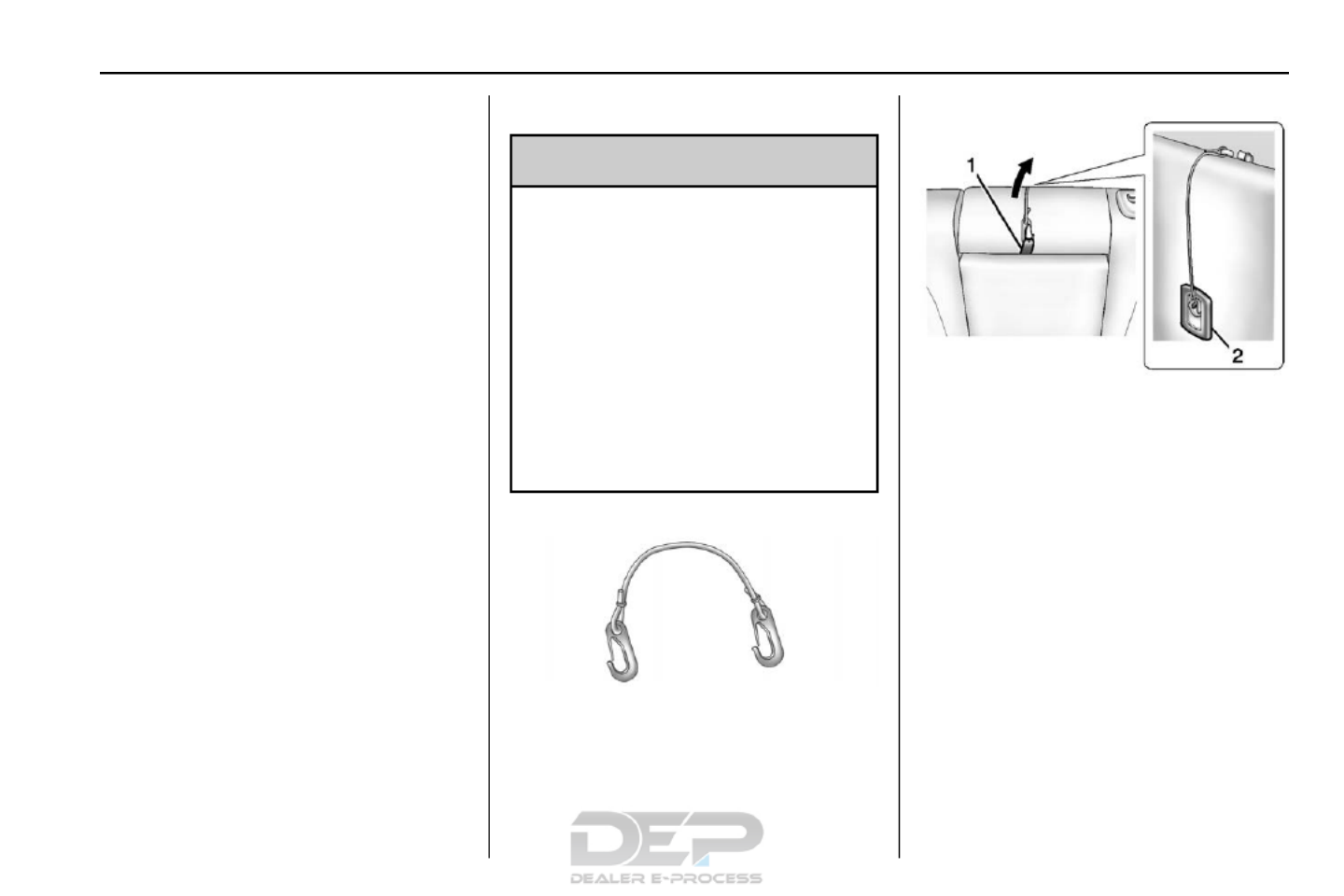
Seats and Restraints 85
6. If the child restraint has a top
tethe r, follow the child restraint
manufacturer's instructions
regarding the use of the top
tether. See Lower Anchors and
Tethers for Children (LATCH
System) 770for more
information.
7. Before placing a child in the
child restraint, make sure it is
securel y held in place. To
check , grasp the child restraint
at the safety belt pat h a nd
attempt to move it side to side
and back and fo rth. When the
child restraint is properly
installed, t here should be no
more tha n 2 .5 cm (1 in) of
movement.
To remove the child restraint,
unbuckle the vehicle safety belt and
let it return to the stowed position.
If the top tether is attach ed to a top
t ether a nchor, disconnect i t.
Armrest Retaining Strap
{Warning
A rear center armrest that is not
properly st owed and secured
cou ld fall forward during a sudden
stop or collision. T he armrest
could contact an infant secured in
a rear facing chil d restraint in the‐
center seat position. Fasten the
retaining s trap on to the stowed
armrest before installin g a rear‐
facing chil d restraint in t he rear
center seat position.
When new, the vehicle's glove box
materi als included an armrest
retaining strap. Use it to secure the
center armrest before in stalling a
rear-facing child restraint in the
second row center seat position.
Stow th e rear seat cente r armres t.
Attach th e retaining strap to the
armrest lo op (1) and to the center
top tether anchor on the
seatback (2). Make sure the
reta ining strap's clips are firmly
attached.
Install the rear-facing child restraint
using th e child restraint
manufacturer's instructions and the
instructions described previously.
Remove the a rmr est retaining strap
before installing a forward facing
child restrai nt in the center s eat
position, as it may interfere with the
attachment of the top tether to the
top teth er anchor on the seatback.

86 S eats and Restraints
Securing Child Restraints
(Front Passenger Seat)
This vehicle has airbags. A rear
seat is a safer place to secure a
forward-faci ng child restraint. See
Where to Put the Restraint 760.
In addition, the vehicle h as a
passenger sensing system which is
designed to turn off the front
ou tboard passenger frontal airbag
un der certain conditions. See
Passenger Sensing System 650
and Passenger Airbag Status
Indicator 1010for more information,
includ ing important safety
information.
Never put a rear-facing child seat in
t he front. This is because the risk to
the rear-facing child is so great,
if the airba g deploys.
{Warning
A child in a rear-facing child
restraint can be seriously injured
or killed if the fro nt outboard
passenger frontal airbag inflates.
(Continued)
Warning (Continued)
This is because the back of the
rear-facing child restraint would
be very close to the inflating
ai rbag. A child in a forward-facing
child re straint can be se riously
injur ed or killed if the front
ou tboard passenger frontal airbag
inflates and the passenger seat is
in a f orward position.
Even if the passenger sensing
system has turned off the front
outboard passenger frontal
airbag, no syst em is fail-safe. No
one can guarantee that an airbag
will not deploy under some
unusual circumst ance, even
though it is turned off.
Secure rear-facing child restr aints
in a rear se at, even if the airbag
is off. If you secure a
forward-facing chi ld restraint in
the front seat, always move the
(Continued)
Warning (Continued)
front passenger seat as far back
as it will go. It is better to secure
the child restraint in a rear seat.
See Passenger Sensing System
065 for additional information.
If the child restra int uses a top
tether, see Lower Anchors and
Tethers for Children (LATCH
System) 770for top tether anchor
locations.
Do not s ecure a child seat in a
position wit hout a top tether anchor
if a national or local law requires
that the top t ether b e anchored, or if
the instructions that come with the
child restr aint say that the top strap
mu st be anchored.
In Canada, the law requires that
forward-facing child restraints have
a top tether, a nd that the tet her be
attached.

Seats and Restraints 87
W hen usi ng the lap-shoulder belt to
secure the child restraint in this
position, follow the instructions that
came with the child restraint and the
following instructions:
1. Move the s eat as far back as it
will go before securing the
forward-facing child restraint.
When the passenger sensing
system has turned off the front
outboard passenger frontal
airba g, the off indicator on the
passenger airbag status
ind icator should light and stay
lit when you s tart the vehicl e.
See Passenger Airbag Status
Indicator 1010.
2. Put the child restraint on
the seat.
3. Pick up the latch plate, and run
the lap and shoulder portions
of the vehicle's safety belt
through or around the restr aint.
The child restr aint in structions
will show you how.
Tilt the latch plate to adjust the
belt if needed.
4. Push the latch plate into the
buckle until it clicks.
P osition the release button on
the buckle, so t hat the safety
belt could be quickly unbuckled
if necessary.
5. Pull the shoulder belt all the
way out of the retractor to set
the lock . When the retractor
lock is set, the belt can be
tightened but not pulled out of
the retractor.

88 S eats and Restraints
6. To tighten the belt, p ush down
on the child restraint, pull the
shoulder portion of the belt to
tighten the lap portion of the
belt, and feed the shoulder belt
back i nto the retractor. When
installing a fo rwa rd-facing child
restrain t, it may be helpful t o
use your knee to p ush down on
the child restraint as y ou
tighte n the belt.
Try to pull the belt out of the
retractor to make sure th e
retractor is locked. If the
retract or is not locked, repeat
Steps 5 and 6.
7. Before placing a child in the
child restraint, make sure it is
securel y held in place. To
check , grasp the child restraint
at the safety belt pat h a nd
attempt to move it side to side
and back and fo rth. When the
child restraint is properly
installed, t here should be no
more tha n 2 .5 cm (1 in) of
movement.
If the airbag is off, the off indicator in
the passenger airbag status
indicator will come on and stay on
w hen the vehicle is started.
If a child rest raint h as been installed
and the on indicator is lit, see If the“
On Indicat or is Lit for a Child
Restraint under”Passenger Sensing
System 650.
To r emove the child restraint,
unbuckle the vehicle safety belt and
let it return to the stowed position.

Storage 89
Storage
Storage Compartments
Storage Compartments . . . . . . . . 89
Glove Box . . . . . . . . . . . . . . . . . . . . . 89
Cupholders . . . . . . . . . . . . . . . . . . . . 89
Center Console Storage . . . . . . . 8 9
Additional Storage Features
Cargo Cover . . . . . . . . . . . . . . . . . . . 90
Car go Tie- Downs . . . . . . . . . . . . . . 90
Con venience Net . . . . . . . . . . . . . . 90
R oof Rack System
Roof Rack Sy stem . . . . . . . . . . . . . 90
Storage
Compartments
{Warning
Do not store heavy or sharp
objects in storage compartments.
In a cr ash, these objects m ay
cause the cover to open and
could result in injury.
Glove Box
Open the glo ve box by lifting up on
the lever.
Cupholders
Two cupholder s are in the center
console. Cupholders may be located
in the second row seat armrest. To
access, pull the armrest down.
Center Console Storage
There is storage in the center
console; lift t he lever on the front to
open. There may be a USB port and
auxil iary input jack inside.

90 Storage
Additional Storage
Features
Car go Cover
For vehicles with a cargo cover, use
it to cover items in the rear of the
vehicle.
To remove the cover from th e
vehicle, pull both ends toward each
othe r. To reinstall, place each end of
the cover in the holes behind the
rear seat.
Car go Tie- Downs
The ve hicle may be e quipped with
four cargo tie-dow ns located in the
rear compartment.
Convenience Net
This vehicle may have a
conv enience ne t in the rear of the
vehicle. Attach it t o the cargo
tie-downs for storing small loads.
Do not use the net to store heavy
loads.
Roof Rack System
{Warning
If something is carried on top of
the vehicle that is longer or w ider
than t he roof rack like paneling,—
plywood, or a mattress the—
wind can catch it while the vehicle
is being driven. T he item being
carried could be violently torn off,
and this could cause a collision
and damage the vehicle. Never
carry something longer or wider
than the roof rack on top of the
ve hicle unless using a GM
certified accessory carrier.
If equipped, the roof rack can be
used to load items. For roof racks
that do not have crossrails included,
GM certified crossra ils can be
purchased as an acces sory. See
your dealer.

Storage 91
Caution
Lo ading cargo on the roof rack
that weighs more than 100 kg
(220 lb) o r hangs over the rear or
sides of the vehicle ma y damage
the ve hicle. Load cargo so th at it
rests evenly between the
crossrails, making sure to fasten
carg o securely.
To prevent damage or loss of cargo
when driving, check to make sure
crossrails and cargo are securely
fasten ed. Loading cargo on the roof
rack will make the vehicle s ce nter’
of gravity higher. Avoid high speeds,
sudden st arts, sharp t urns, sudden
braking, or abrup t maneuvers;
otherwise it may result in loss of
control. If driving for a long distance,
on rough roads, or at high speeds,
occasionally stop the vehicl e to
make sure the cargo remai ns in its
place. Do not exceed the maximum
vehicle capacity when loading the
vehicl e. For more informat ion on
vehicle capacity and l oading, see
Vehicle Load Limits 1550.

92 Instruments and Controls
Instru ments a nd
Controls
Controls
Steering Wheel Adjustment . . . . 93
Steering Wheel Controls . . . . . . . 9 3
Horn . . . . . . . . . . . . . . . . . . . . . . . . . . . 93
Windshield Wiper/Washer . . . . . . 93
Rear Window Wiper/Washer . . . 94
Compass . . . . . . . . . . . . . . . . . . . . . . 95
Clock . . . . . . . . . . . . . . . . . . . . . . . . . . 95
Power Outlets . . . . . . . . . . . . . . . . . 96
War ning Lights, Gauges, and
Indicators
Warning Lights, Gauges, and
Indicators . . . . . . . . . . . . . . . . . . . . 97
Instrument Cluster . . . . . . . . . . . . . 98
Speedometer . . . . . . . . . . . . . . . . . . 99
Odometer . . . . . . . . . . . . . . . . . . . . . . 99
Tachometer . . . . . . . . . . . . . . . . . . . . 99
Fuel Gaug e . . . . . . . . . . . . . . . . . . . . 99
Engine Coolant Temperature
Gauge . . . . . . . . . . . . . . . . . . . . . . 100
Safety Belt Reminders . . . . . . . . 100
A irbag Readiness Light . . . . . . . 10 1
Passenger Airbag Status
Indicator . . . . . . . . . . . . . . . . . . . . 101
Charging System Light . . . . . . . 102
Malfunction Indicator Lamp
(Ch eck Engine Light) . . . . . . . . 103
Brak e System Warning
Light . . . . . . . . . . . . . . . . . . . . . . . . 104
Antilock Brake S ystem (ABS)
Warning Light . . . . . . . . . . . . . . . 105
Lane D epar ture W arning
(LDW) Light . . . . . . . . . . . . . . . . . 106
Forward Coll ision Alert (FCA)
Warning Light . . . . . . . . . . . . . . . 106
Vehicle Ahead Indicator . . . . . . 106
Traction Off Light . . . . . . . . . . . . . 106
StabiliTrak
®
OFF Ligh t . . . . . . . . 107
Traction Control Sy stem (TCS)/
StabiliTrak
®
Ligh t . . . . . . . . . . . 107
Tire Pressure Light . . . . . . . . . . . 107
Engine Oil Pressure Light . . . . 108
Fu el Economy Light . . . . . . . . . . 108
Low Fuel Warning Light . . . . . . 109
Security Light . . . . . . . . . . . . . . . . . 109
High-Beam On Light . . . . . . . . . . 109
F ront Fog Lamp Light . . . . . . . . . 109
Lamps On Reminder . . . . . . . . . . 110
Cru ise Control Light . . . . . . . . . . 110
Information Displays
Driver Information
Center (DIC) . . . . . . . . . . . . . . . . 110
Vehicle Messages
Vehicle Messages . . . . . . . . . . . . 113
Battery Voltage and Charging
Messages . . . . . . . . . . . . . . . . . . . 113
Br ake System Messages . . . . . 114
Com pass Messages . . . . . . . . . . 114
Cruise Control Message s . . . . . 11 4
Door Ajar Messages . . . . . . . . . . 114
Engine Cooling System
Messages . . . . . . . . . . . . . . . . . . . 114
Engine O il Messages . . . . . . . . . 115
Engine Power Messages . . . . . 115
Fuel System Mess ages . . . . . . . 116
Key and Lock Messages . . . . . . 116
Object Detection System
Messages . . . . . . . . . . . . . . . . . . . 116
Ride Control System
Messages . . . . . . . . . . . . . . . . . . . 117
Airbag System M essages . . . . . 118
Securit y Messages . . . . . . . . . . . 118
Service Vehicle Messages . . . . 118
Tire Messages . . . . . . . . . . . . . . . . 118
Transmission Messages . . . . . . 119
Vehicle Reminder
Messages . . . . . . . . . . . . . . . . . . . 119
Vehicle Personalization
Vehicle Personalization . . . . . . . 12 0

Instruments and Controls 93
Universal Remote System
Universal Remote System . . . . 1 25
Universal Remote System
Programming . . . . . . . . . . . . . . . 125
Universal Remote System
Operation . . . . . . . . . . . . . . . . . . . 128
Controls
Steering Wheel
Adjustment
To adjust the steering wheel:
1. Pull the le ver do wn.
2. Move the steering wheel up
or down.
3. Pull or push the stee ring wheel
cl oser or awa y from you.
4. Pull the lever up to lock the
steering wheel in pl ace.
Do not adjust the steering wheel
while drivi ng.
Steering Wheel Controls
The infotainm ent system can be
operated by using the steering
wheel controls . See "Steering
Wheel Controls" in the infotainment
manual.
Horn
Press on th e steering wheel pada
to sound the horn.
Windshield Wiper/Washer
The windshield wipe r/washer lever
is located on the right side of the
steering column. Wit h the ign ition in
ACC/ACCESSORY or ON/RUN/
STA RT, move the windshield wiper
lever to select the wiper speed.
HI : Use for fast wipes.
LO : Use for slow wipes.

94 Instruments and Controls
INT (I ntermittent Wipes) : Move
the lever up to INT for in termittent
wipes, then turn the 3INT band
up for more frequent wipes or down
for less fr equent wipes.
OFF : Use to turn the wipers off.
1X (Mist) : For a single wipe, briefly
move the w iper le ver down. For
several wipes, hold th e wiper
lever down.
nLFRONT (Windshield
Washer) : Pull the windshield wiper
lever toward you to spray windshield
washer fluid and activate the wipers.
The w ipers will continue until the
lever is released or the maximum
wash time is reached. When the
windshield wiper lever is released,
additional wipes may occur
depending on how lo ng the
windshield washer had been
activated. See Washer Fluid 2150
for information on filling the
windshield washer fluid reservo ir.
{Warning
In freezing weather, do not use
t he washer until the windshield is
warmed. Otherwise the washer
fluid can form ice on the
windshield, blocking your vision.
Clear snow and ice from th e wiper
blades before using them. If frozen
to the windshield, carefu lly loosen or
thaw them. Damaged blades should
be replaced. See Wiper Blade
Replacement 2190.
Heavy sn ow or ice can overload the
wiper mo tor.
Wiper Parking
If t he ignition is turned to LOCK/
OFF while the wipers are on L O, HI,
or INT, they will immediately stop.
If the windshield wi per lever is t hen
moved to OFF before the driver
door is o pened or within 10 min utes,
the wipers will restart and move to
the b ase of the windshiel d.
If t he ignition is turned to LOCK/
OFF while the wipers are perfo rming
wipes due to windshield washing,
the wipers continue to run until they
reach the base of the wind shield.
Rear Window Wiper/
Washer
The rear wiper controls are on the
end of the windshield wiper lever.
ON : Press the upper portion of the
button for cont inuous rear wi ndow
wipes.

Instruments and Controls 95
OFF : The rear wiper turns off when
the button is returned to the middle
position.
INT (Intermittent Rear Wipes) :
P ress the lower portion of th e button
to set a delay between wipes.
a(Rear Washer) : Push the
wind shield wipe r lever forward to
spray washe r fluid on the rear
w indow. The lever returns to its
starting position when released.
Rear Wiper Arm Assembly
Protection
When using an automatic car w ash,
move the rear wiper control to OFF.
This disables the rear wiper.
If the transmission is in N (Neutral)
and the vehicle speed is very slow,
th e rear wiper will a utomatically stop
at the base of the rear windo w.
The w iper operations return to
normal when the transmiss ion is no
longer in N (Neutral) or the vehicle
s peed has i ncreased.
The windshield washer reservoir is
used for the windshield and the rear
window. Check the fluid level in the
reservoir if ei ther washer is not
working. See .Washer Fluid 2150
Compass
The vehicle may have a comp ass
display in the Driver Information
Center (DIC). The compass re ceives
its heading and oth er infor mation
from the Global Positioning
System (GPS) antenna, StabiliTrak,
and vehicle speed informati on.
Avoid covering the GPS antenna,
located on the roof, for long periods
of time with objects that may
interfer e with the antenna's ability to
receive a satellite signal. The
compass system is designed to
operate for a certain number of
miles or degrees of turn before
needing a signal from the GPS
satellites. Wh en the compass
displ ay shows CAL, drive th e
vehicle for a short di stance in an
open area where it can receive a
GP S signal. T he compass system
will automatically determine when
the GPS signal is restored and
provide a heading again.
Clock
The infotainmen t system controls,
are used to access the t ime and
date settings th rough the menu
system. See Using the System in“ ”
the infotainm ent manua l.
Setting the Clo ck Using the
Faceplate
To set the time and date:
1. Turn the infotainment
system on.
2. Pres s the CONFIG button and
select Time Settings, or press
the H button.
3. Select Set Time.
4. Turn the MENU/SEL knob to
adjust the highlighted value.
5. Press the MENU/SEL knob to
select the next value.

96 Instruments and Controls
6. To save the time a nd return to
the Tim e Settings menu, pr ess
the MENU/SEL knob after
ad justing the time.
To set t he 1 2/24 hour fo rmat:
1. Turn the inf otain ment
system on.
2. Pres s the CONFIG button and
select Time Settings, or press
the H button.
3 . H ighlight 12 hr/24 hr Format.
4. Press the MENU/SEL knob t o
select th e 12 Hour or 24 Hour
display format.
Setting the Clock Using t he
Touchscreen
To set the time:
1. Touch CONFIG.
2. To uch Time to d isplay other
options within that feature.
3. Touch + or to decrease o r−
increase the Hours and
Minutes display ed on the clock.
12/24 HR Format : Touch 12 Hour
for standard time; touch 24 Hour for
military time.
Day + or Day :−Touch Day + or
Day to increase or decrease−
the day.
Display : Touch Display to turn the
display of the time on the screen on
or off.
Power Outlets
The accessory power outlets can be
used to connect electrical
e quipment, such as a cell phone or
MP3 player.
There are fo ur accessory power
outlets: inside the o pen storage
area in front of the shif t lever, inside
the center console storage, on the
r ear of the center console storage,
and i n the rear cargo compartm ent.
To use the outlets, remove the cover
and close wh en n ot in use.
Caution
Leaving electrical equipment
plugged in for an extend ed period
of time while the vehicl e is off will
drain the battery. Power is always
supplied to the rear cargo outlet.
Always unpl ug electrical
e quipment when not i n use and
do not plu g in equipment that
exceeds the maximum 20 am pere
rating.
Certain acces sory plugs may not be
compatible w ith the acces sory
power outlets and could overlo ad
vehicle and adapter f uses . If a
problem is experienced, see your
dealer.
When adding electrical equipment,
be sure to follo w the installation
instru ctions included with the
equipment. See Add-On Electrical
Equipment 1950.

Instruments and Controls 97
Caution
Hanging heavy equipment from
the power outlet can cause
damage not covered by the
vehicle warranty. The power
out lets are designed for
accessory p ower plugs o nly, such
as cell phone cha rge cords.
Warning L ights,
Gauges, and
Indicators
Warning lights and gauges can
sign al that something is wron g
befor e it b ecomes serious enough
to cause an expensive r epair or
replacement. Paying attenti on to the
warning lights and gauges could
preven t injury.
Some warning lights com e on b riefly
when the engi ne is started to
indicate they are working. When
one of the warning lights comes on
and stays on while driving, or when
one of the gauges shows there may
b e a problem, check t he section that
explains what to do. Waiting to do
repairs can be cost ly and even
dangerous.

98 Instruments and Controls
Instrument Cluster
English Shown, Metric Similar

Instruments and Controls 99
Speedometer
The speedometer s hows the
veh icle's speed in e ither kilometers
per hour (km/h) or miles per
hour (mph).
Odometer
The o dometer shows how far th e
vehicle has been driven, in either
kilometers or miles.
Tachometer
The tachometer d isplays the e ngine
speed in revolutions per
minute (rpm).
Caution
If the engin e is operated with the
rpm s in the warning area at the’
high end of the tachometer, the
vehicle cou ld be damaged, and
t he damage would not b e covered
by the vehicle warranty. Do not
operate the engine with the rpm s’
in the warn ing area.
Fuel Gauge
Metric
English
When the ignition is on, the fuel
gauge shows about how much fuel
the vehicle h as left in the fuel tank.
An arrow on the fuel gauge
indicates the side of the ve hicle the
fuel door is on.
The gauge will first indicate empty
before the vehicle is out of fuel and
the low fuel light comes on, but the
vehicle's fuel tank should be
filled so on.
Here are some situations that can
occur with the fuel gauge. None of
these indicate a problem with the
fuel gauge.
. At the service station, the fuel
pum p shuts off before the gauge
reads full.
. It takes a little more or less fuel
to fill up than the gauge
indicated. For example, the
gauge may have indicated the
tank was half f ull, but it actually
took a lit tle more o r less than
half the ta nk's capacity to fill
the tank.
. The gauge mo ves a little while
turning a corner or speeding up.

100 Instruments and Controls
. The gauge takes a few seconds
to stabilize after the ignit ion is
t urned o n, and goes back to
empty when the ignition is
turned off.
Engine Coolant
Temperature Gauge
Metric
English
This gauge measure s the
temperature of the vehicle's engine.
If the indicato r needle moves to the
hot side of the gauge toward the
colored line, the engine is too hot.
If the vehicle has been operated
under n ormal driving conditions, pull
off the road, stop the vehicl e, and
turn off th e engine as soon as
possible.
Safety Belt Reminders
Driver Safety Belt Reminder
Light
T here is a d river safety belt
reminde r light on the instrument
cluster.
When the vehicle is started, this
light flashes and a chime may come
on to remind the driver to fasten
the ir safety belt. Then the light stays
on solid until the belt is buckled.
This cycle may continue several
times if the driv er remains or
becomes unbuckled while th e
vehicle is mo ving.
If the driver safety belt is buckled,
neither the light nor the chime
comes on.

Instruments and Controls 101
Passenger Safety Belt
Reminder Light
There is a passenger safety belt
reminder light near the passenger
airbag status indicator. See
Passenger Sensing System 650 .
When the vehicle is started, this
light flashes and a chime may come
on to remind passengers to fasten
their safety belt. Then the light stays
on solid until the belt is buckled.
This cycle continues several times if
the passenger remains or becomes
unbuckled while the vehicle is
moving.
If the passenger safety belt is
buckled, neither the chime nor the
light comes on.
The front passenger safety belt
reminder light and chime may turn
on if an object is put on the seat
such as a briefcase, handbag,
grocery bag, laptop, or other
electronic device. To turn off the
reminder light and/or chime, remove
the object from the seat or buckle
the safety belt.
Airbag Readiness Light
This light shows if there is an
electrical problem with the airbag
system. The system check includes
the airbag sensor(s), passenger
sensing system, the pretensioners,
the airbag modules, the wiring, and
the crash sensing and diagnostic
module. For more information on the
airbag system, see Airbag System
0 59.
The airbag readiness light comes on
for several seconds when the
vehicle is started. If the light does
not come on then, have it fixed
immediately.
{Warning
If the airbag readiness light stays
on after the vehicle is started or
comes on while driving, it means
the airbag system might not be
working properly. The airbags in
the vehicle might not inflate in a
crash, or they could even inflate
without a crash. To help avoid
injury, have the vehicle serviced
right away.
If there is a problem with the airbag
system, a Driver Information Center
(DIC) message may also come on.
See Airbag System Messages
0 118.
Passenger Airbag Status
Indicator
The vehicle has a passenger
sensing system. See Passenger
Sensing System 650 for important
safety information. The overhead
console has a passenger airbag
status indicator.

102 Instruments and Controls
United States
Canada and Mexico
When the vehicle is started, the
passenger airbag status indicator
will light ON and OFF, or the symbol
for on and off, for several seconds
as a system check. Then, after
several more seconds, the status
indicator will light either ON or OFF,
or either the on or off symbol to let
you know the status of the front
outboard passenger frontal airbag.
If the word ON or the on symbol is
lit on the passenger airbag status
indicator, it means that the front
outboard passenger frontal airbag is
allowed to inflate.
If the word OFF or the off symbol is
lit on the passenger airbag status
indicator, it means that the
passenger sensing system has
turned off the front outboard
passenger frontal airbag.
If, after several seconds, both status
indicator lights remain on, or if there
are no lights at all, there may be a
problem with the lights or the
passenger sensing system. See
your dealer for service.
{Warning
If the airbag readiness light ever
comes on and stays on, it means
that something may be wrong
with the airbag system. To help
avoid injury to yourself or others,
have the vehicle serviced right
away. See Airbag Readiness
(Continued)
Warning (Continued)
Light 1010 for more information,
including important safety
information.
Charging System Light
The charging system light comes on
briefly when the ignition is turned
on, but the engine is not running, as
a check to show the light is working.
The light turns off when the engine
is started. If it does not, have the
vehicle serviced by your dealer.
If the light stays on, or comes on
while driving, there may be a
problem with the electrical charging
system. Have it checked by your
dealer. Driving while this light is on
could drain the battery.

Instruments and Controls 103
When this light comes on, the Driver
Information Center (DIC) also
displays a message.
See Battery Voltage and Charging
Messages 1130 .
If a short distance must be driven
with the light on, be sure to turn off
all accessories, such as the radio
and air conditioner.
Mal function Indicator
Lamp (Check Engine
Light)
This light is part of the vehicle s’
emission control on-board
diagnostic system. If this light is on
while the engine is running, a
malfunction has been detected and
the vehicle may require service. The
light should come on to show that it
is working when the ignition is in
ON/RUN and the engine is not
running. See Ignition Positions
0 159.
Malfunctions are often indicated by
the system before any problem is
noticeable. Being aware of the light
and seeking service promptly when
it comes on may prevent damage.
Caution
If the vehicle is driven continually
with this light on, the emission
control system may not work as
well, the fuel economy may be
lower, and the vehicle may not
run smoothly. This could lead to
costly repairs that might not be
covered by the vehicle warranty.
Caution
Modifications to the engine,
transmission, exhaust, intake,
or fuel system, or the use of
replacement tires that do not
meet the original tire
specifications, can cause this light
to come on. This could lead to
costly repairs not covered by the
vehicle warranty. This could also
affect the vehicle s ability to pass’
an Emissions Inspection/
Maintenance test. See
Accessories and Modifications
0 197.
If the light is flashing : A
malfunction has been detected that
could damage the emission control
system and increase vehicle
emissions. Diagnosis and service
may be required.
To help prevent damage, reduce
vehicle speed and avoid hard
accelerations and uphill grades.

104 Instruments and Controls
If towing a trailer, r educe the
amou nt of cargo being hauled as
soon as possible.
If the light continues to flash, find a
safe pl ace to park. Tu rn the vehicle
off and wait at least 10 seconds
before rest arting the engine. If th e
light is still flashing , follow the
previous guideline s and see your
dealer for service as soon as
possible.
If the light is on ste ady : A
malfunction has been detected.
Diagnosis and service may be
required.
Check the following:
. A loo se or missing fuel cap may
cause the light to come on . See
Filling the Tank 1870. A few
driving trips with the cap
properly insta lled may turn the
light off.
. Poor fuel quality can cause
inefficient engine operation and
poor driveability, which may go
awa y once the engine is warmed
up. If th is occurs, ch ange the
fuel brand. It may require at
least one full ta nk of the proper
fuel to turn t he light off. See Fuel
0 184.
I f the light remains on, see your
dealer.
Emissions Inspection and
Maintenance Programs
If the vehicle requires an Emissions
Inspectio n/Maintenance test, the
te st equipment will likely connect to
the vehicle's Data Link
Connector (DLC).
The DLC is un der the instrument
panel to the left of the steering
wheel. Connectin g devices that are
not used to perform an Emissions
Inspection/Maintenance test or to
service the vehicle may affect
vehicle op eration See Add-On
Electrical Equipment 1950. See
you r dealer if assistance is needed.
The ve hicle may not pass
inspection if:
. The light is on whe n the e ngine
is running.
. The l ight does not come on
when the igni tion is in ON/RUN
while the engine is off.
. Critical emission control systems
have not bee n completely
diagnosed. If this happens, the
vehicle would not b e ready for
inspection and might require
several day s of routine driv ing
before the system is ready for
inspection. This can happen if
the 12-volt battery has rece ntly
been replaced or run down, or if
the ve hicle has been recently
serviced.
See your dealer if the vehicle will
not pass or cannot be made r eady
for the test.
Brake System Warning
Light
The vehicle brake s ystem consists
of two hydraulic circuits. If one
circuit is not working, the remaining

Instruments and Controls 105
circuit can still work to stop the
vehicle. For normal braking
performan ce, both circuits need to
be working
Metr ic English
The brake indicator light should
come on briefly as the engine is
started. If i t does not come on have
the vehicle s erviced by your dealer.
When the ignition is on, the brake
system warning light comes on
when the parking brake is set. The
light stays on if the parking brake
does not fully release. If it stays on
a fter the parking brake is fully
released, there is a brake problem.
Have th e b rake syst em inspected
immediately.
{Warning
The brake system might not be
working properly if the brake
system wa rning light i s on.
Driving with the brake system
warning light on can lead to a
crash. If t he light is still on after
the vehicle has been pulled off
the road an d ca refully stopped,
have the vehicle towed for
service.
If the light com es on while drivin g, a
chim e sounds. Pull off the road and
sto p. The pedal mi ght be harder to
push or go closer t o the floor.
It might also take longer to stop.
If the light is still on, have the
vehicle towed for se rvice. See
Towing the Vehicle 2590.
Antilock Brake System
(ABS) Warning Light
For vehicles with the Antilock Brake
System (ABS), this light comes on
briefly when the engine is started.
If the light does not come on, have it
fixed so it will be ready to warn if
there is a problem.
If the ABS li ght comes on and stays
o n while driving, stop as soon as
possible and turn the ignition off.
Start t he engine again to reset the
system. If the l ight stays on after
driving at a s peed above 20 km/h
(13 mph), s ee your dealer for
service. A chime may also sound
when the light comes on steady.
If the regu lar brake system warning
light is n ot on, the vehicle still has
brakes, but not antilock brakes.
If the regu lar brake system warning

106 Instruments and Controls
light is also on, the vehicle d oes not
have antilock b rakes and there is a
problem with the regular brakes.
See Brake System Warning Light
0 104.
See Brake System Messages 1140
for all brake related DIC messages.‐
Lane Departure Warning
(LDW) Light
If equipped, this light, located in the
center of the instrument panel,
comes on briefly whil e starting the
vehicle.
If it does not come on, have the
veh icle service d.
This light is green if LDW is on and
ready to operate.
This light changes to amber and
flashe s to indicate that the lane
m arking has been crossed without
using a turn signal in that direction.
See Lane Departure Warning (LDW)
0 183.
Forward Collision Aler t
(FCA) Warning Light
This light is on the center of the
instrument panel.
The red forward collisi on alert
comes on and flashes when a
vehicle is being approached too
rapidly.
The forward collision alert stays on
when following a vehicle much too
closely.
See Forward Collision Alert (FCA)
System 1790.
Vehicle Ahead Indicator
If equipped, this indicator will
display green when a vehicle is
detected ahead
See Forward Collision Alert (FCA)
System 1790.
Traction Off Light
This light comes on b riefly while
starting the engine. I f it does not,
have the vehicle serviced by your
dealer. If the system is working
normally, the indicator light then
turns off.

Instruments and Controls 107
The t raction off light comes on when
the Traction Control System (TCS)
has been turned off by pressing and
releasing the TCS/StabiliTrak
button.
This light and the StabiliTrak OFF
light come on when StabiliTrak is
turned off.
If the TCS is off, wheel spin is not
limited. Adjust driving accordingly.
See Traction Control/Electronic
Stability Control 1710.
StabiliTrak
®
OFF Light
This light comes o n b riefly while
starting the vehicle. If it does not,
have the vehicle serviced by your
dealer.
This light comes on when the
StabiliTrak system is turned off.
If StabiliTrak is off, the Traction
Control System (TCS) is a lso off.
If the StabiliTr ak and TCS are off,
the system does n ot assist in
contr olling the vehicle. Turn on the
TCS and the StabiliTrak systems
and the warning light t urns off.
See Traction Control/Electronic
Stability Control 1710.
Traction Control System
(TCS)/StabiliTrak
®
Light
This light comes on briefly when the
engine is started.
I f the light does not come on, have
the vehicle s erviced by your dealer.
If the system is working normally,
the indicator light turns off.
If the light is on and not fl ashing, the
TCS and potentia lly th e StabiliTrak
system have been disabled. A DIC
messag e may display. Check the
DIC messages to det ermine which
feature( s) is no longer functioning
and whether the vehicle requires
service.
If the ligh t is on and flashing, t he
TCS and/or the S tabiliTrak system
is actively working.
See Traction Control/Electronic
Stability Control 1710.
Tire Pressure Light
For ve hicles with the Tire Pressure
Monitor System (TPMS), this light
comes on briefly when the engin e is
started. It provides information
about tire pressures and the TPMS.

108 Instruments and Controls
When the Light Is On St ead y
This indicates that one or mor e of
the tire s are significantly
underinflated.
A D river Information Center (DIC)
tire pressure message may also
display. See Tire Messages 1180.
Stop as soon as possible, and
inflate the tires to the pressure value
shown on the Tire and Loading
Information label. See Tire Pressure
0 236.
When the Light Flashes Fi rst and
Then Is On Steady
If the light fla shes for about a minute
and then stays on, there may be a
problem with the TPMS. If the
problem is not co rrected, the light
will come on at every ignition cycle.
See Tire Pressure Monitor
Operation 2380.
Engine Oil Pressure Light
Caution
Lack of proper engine oil
maintenance can damage the
engine. Driving with the engine oil
low can also damage the engine.
The repairs would not be covered
by the vehicle warranty. Check
the oil level as so on as possible.
Add oil if re quired, but if the oil
level is within the operating range
and the oil pres sure is still low,
have the vehicle serv iced. Always
fol low the maintenance schedule
for changing engine oil.
This light should come on briefly a s
the engine is started. If it does not
come o n, have the vehicle serviced
by your dealer.
If t he light co mes on and stays on, it
means that oil is not flowing through
the engine properly. The vehicle
could be low on oil and might have
some other system problem. See
your dealer.
Fuel Economy Light
For vehicles with the Fuel Economy
Mo de light, it comes on when the
eco (economy ) button near the sh ift
lever is pressed. For vehicles with a
Driver Information Center (DIC) an
ECO MODE ON message displays.
See Fuel System Messages 1160.
Press the button again to turn off
the light and exit the f uel
s aver mode.

Instruments and Controls 109
Low Fuel War ning Light
English Shown, Metric Similar
This light comes on for a few
seconds when the ignitio n is turned
on as a check to indicate it is
working. If it does not come on,
have it fix ed.
The low fuel wa rning light is a circle
located on the fu el gauge. This li ght
comes on a nd a chime sounds
periodically when the vehicle is low
on fuel. The light goes off when fuel
is added to the fuel t ank.
For vehicles with a Driver
Informati on Center (DIC), see Fuel
System Messages 1160for more
information.
Security Light
The security light s hould come on
briefly as the engine is started. If it
does not come on, have the vehicle
serviced by your dealer. If the
system is working normally, the
indicator light turns off.
If the light stays on and the engine
does not start, there could be a
problem w ith the theft-deterrent
system. See Immobilizer Operation
0 37.
High-Beam On Light
T he high beam on light comes on‐
when the high-beam headlamps are
in use.
See Headlamp High/Low-Beam
Changer 1290for more information.
Front Fog Lamp Light
The fog lamp light comes on when
the fog lamps are in use .
The light goes out when the fog
lamps are turned off. See Fog
Lamps 1320for more information.

110 Instruments and Controls
Lamps On Reminder
For vehicles with the lamps on
reminde r light, i t comes on w hen the
lights are in use .
Cr uise Control Light
For vehicles with cruise control, the
cruise control light is white when the
cruise control is on and ready, and
turns green when the cruise control
is set and active.
The light turns off when the cruise
control is t urne d off. See Cruise
Control 1730.
I n f o rmation Displays
Driver Information
Center (DIC)
The vehicle may have a Driver
Information Center (DIC). It displays
information about t he vehicle and
warning messages if there i s a
system problem detected. DIC
messages display in the ce nter of
the instrument cluster. See Vehicle
Messages 1130.
The vehicle may also have features
that can be cu stomized through the
controls on the radio. See Vehicle
Personalization 1200.
DIC Operatio n and Displays
Use the DIC button s located i n the
center of the instrument pa nel to
access different displays. The DIC
displays trip, fuel, vehicle system
information, and warning m essages.
It also shows the shift lever position,
the odometer, and the direction the
vehicle is driv ing.
DIC Buttons
MENU : Press this button to get to
the Trip/Fuel M enu and the Veh icle
Information Menu.
Q Ror : Use these buttons to scroll
through the items in each men u.
A small marker will m ove along the
page as you scroll through the
items. This shows where each page
is i n the menu.
SET/CLR (Set/Clear) : Use this
button to set or clear the menu item
when it is displayed.
Trip/Fuel Menu Items
Press the MENU button until Trip/
Fuel Inform ation Menu is displayed .
Then press Rto scroll through the
following menu items:

Instruments and Controls 111
. Digital Speedometer
. Trip 1
. Trip 2
. Fuel Range
. Average Fuel Economy
. Best Average Fuel Economy
. Average Vehicle Speed
.Timer
.Navigation
. Blank Display
Digital Speedometer
The speedometer shows how fa st
the vehicle is movin g in either
kilo meters per hour (km /h) or miles
p er hour (mph). The speedo meter
cannot be re set.
Trip 1 and Tr ip 2
This display shows the current
distance trave led, in either
ki lometers (km) or miles (mi), since
the last reset for the trip odometer.
The trip odometer can be reset to
zero by p ressing SET /CLR while the
trip odometer display is showing.
Fuel R ange
This display shows the approximate
distance the vehicle can be driven
with out refueling. The fuel range
estimate is based on an average of
the vehicle's fuel economy over
recent driving history and the
amount of fuel remaining in the fuel
tank. Fuel range cannot be reset.
Averag e Fuel Ec onomy
This display shows the approximate
average liters per 100 kilometers (L/
100 km) or mi les per gal lon (mpg).
This number is calculated based on
t he number o f L/100 km (mpg)
recorded since the last time this
menu item was reset. Th is number
reflects only t he a ppro ximate
average fuel economy that the
vehicle has right now, and will
change as driving conditions
change. The fuel economy can be
reset by pressing SET/CL R while
the Average Fuel Economy d isplay
is showing. The display may not
reset to zero.
Best Average Fuel Ec onomy
The right hand side displays the
best average fuel economy (AFE )
that is achieved for a selected
distance. The left hand side displays
a running average of fuel economy
for th e most rece ntly traveled
selected distance. The center of the
Best AFE menu includes a digital
rea dout and bar graph to s how the
instantaneous fuel economy.
Quickly pr ess the SET/CLR button
to display a page for selecting one
of the distance options. Move the
up/down arrow to choose the
selection, and SET/CLR to change
the setting.
When viewing best AFE, a sever al
s econd press and ho ld of SET /CLR
will reset the best value. The best
value will s how - - - until the“ ”
s elected distance has been
traveled.
The display provides feedback on
how current driving behavior in the
bar g raph aff ects the running
ave rage in the left display and how
well recent dr iving compares to the
best that has been achieved.

112 Instruments and Controls
Averag e Vehicle Speed
This display shows the average
speed of the vehicle in kilometers
per hour (km/h) or miles per
hour (mph). This average is
calcula ted based on the various
vehicle speeds recorded since the
last reset of this value. The average
speed can be reset by pressing
SET/CLR while the Average Vehicle
Speed display is sho wing.
Timer
This display can be used as a timer.
To start the timer, press SET/CLR
while Timer is di splayed. The
display will show the amount of time
that has pas sed since the timer was
last reset, no t including time the
ignition is off. Time will continue to
be counted as long as the ignition is
on, even if another display is bei ng
shown on the DIC. The timer wi ll
record up to 99 hours, 59 minutes
and 59 seconds (99:59:5 9) after
which the display will return to zero.
To stop the timer, press SET /CLR
briefly while Timer is displayed. To
reset the timer to zero, press and
hold SET/CLR.
Navigation
This display is used for the OnStar
or Navigation Syst em Turn-by-Turn
guidance, if equipped . See OnStar
Overview 3020or the infotainment
manual, if equipped.
Blank Display
This display s hows no info rmation.
Vehicle Inf ormation Menu
Items
Press the MENU button until Vehicle
Information Menu is displayed. Then
press Rto scroll through the
following menu items:
.Unit
. Tire Pressure
. Remaining Oil Life
. Blank Display
Unit
Press SET/CLR to enter the unit
menu. Then press Q Ror to switch
between METRI C or US when the
Uni t display is active. Press SET/
CLR to confirm t he setting. This will
change the displays on the cl uster
and DIC to either metric or English
(U S) measurements.
Tire Pressure
The display will show a vehicle with
the appro ximate pressures of all
four tires. Tire pressure is displayed
in either kilopascal (kPa ) or in
pounds per square inch (psi).
See Tire Pressure Monitor System
0237 Tire Pressure Monitorand
Operation 2380.
Remaining Oil Life
This display sho ws an es timate of
the oil's remaining us eful life.
I f REMAINING OIL LIFE 99% is
d isplayed, that means 99% of the
current oil life remains.
When the remaining oil life is low,
the CHANGE ENGINE OIL SOON
message will appear on the d isplay.
See Engine Oil Messages 1150.
The oil should be changed as soon
as possible. See .Engine Oil 2030
In ad dition to the engine oil lif e
s ystem mo nitoring the oil life,
addit ional maintenance is

Instruments and Controls 113
recommended in the Maintenance
Schedule in t his manual. See
Maintenance Schedule 2720.
Remember, the Oil Life display must
be reset after each o il change. It will
not reset i tself. Also, be careful not
to reset the Oil Life di splay
accide ntally at any time other than
when t he oil has just been changed.
It can not be reset a ccurately until
the next oil ch ange. To reset the
engine oil life system, press SET/
CLR while t he O il Life display is
active . The display will ask for
confirmation of a reset. Press Q or
Rto select Yes or No. Then press
SET/CLR to confirm the selection.
See .Engine Oil Life System 2060
Blank Display
This display s hows no i nformation.
Compass
The veh icle may have a compass in
the Driver Information Center (DIC).
See .Compass 950
Vehicle Messages
Messages are displ ayed on the DIC
to notify the driver that the status of
the vehicle has changed and that
so me action may be ne eded by the
driver to correct the condition.
Multiple messages may appear one
after another.
Some mes sages may not requi re
immediate action, but you ca n p ress
SET/CLR to acknowled ge that you
received the messages and to clear
them from the display. Some
messages cannot be cleared fro m
the DIC display because they are
more urg ent. These messages
require a ction before t hey can be
cleared. You should take any
messages t hat appear on the
display seriously and remember t hat
clearing the messages will only
make the messages disappear, n ot
correct the problem. You will f ind the
possible messages that can be
displayed and some information
about them grou ped by subject in
the following information.
Battery Voltage and
Charging Me ssages
BATTERY SAVER ACTIVE
This mes sage displays when the
vehicle has detected that the battery
voltage is dropping beyond a
reasonable point. The bat tery saver
system starts reducing features of
the vehicle that may be noticed. At
the point that features are disabled,
this message di splays. Turn off
unnecess ary accessories to al low
the ba ttery to recharge.
LOW BATTERY
This message is displayed when the
battery voltage is low. See Battery -
North America 2170.
SERVICE BATTERY
CHARGING SYSTEM
This message is d isplayed when
there is a fault in the battery
charging system. Tak e the vehicl e to
your dealer for service.

114 Instruments and Controls
Brake System Messages
BRAKE FLUID LOW
T his message is displayed when the
brake fluid level is low; see Brake
Fluid 2160.
RELEASE PARKING B RAKE
This message is displayed as a
reminder that the parking brake is
on. Release it before you attempt to
drive.
Compass Messages
CAL
T his message is displayed when the
compass needs to be calibra ted.
See .Compass 950
– –
D ashes will be displayed if the
compass needs service. See your
dealer for service.
Cr uise Control Mes sages
APPLY BRAKE BEFORE
CRUISE
If this m essage displays when
attempting to activat e cruise control,
apply the brake pedal and try again.
CRUISE SET TO XXX
This mes sage displays wh en the
cruise control is set and shows the
speed it was set to. See Cruise
Control 1730.
Door Ajar Messages
DOOR OPEN
A door open symbol will be
d isplayed on the DIC showing which
door is o pen. If the vehicle has been
shifted out of P (Park), a DOOR
OPEN message will also be
displayed. Close the door
completely.
MANUALLY C LOSE THE
POWER LIFTGATE
This message wi ll d isplay if the
power liftgate encounters m ultiple
obstacles on the same power cy cle.
After removing the obstructions, the
liftgate will resume no rmal power
operation.
REAR ACCESS OPEN
This message wi ll d isplay along wi th
a symbol when the liftgate is open.
Close the liftgate completel y.
Engine Cooling System
Messages
A/C OFF DUE TO HIGH
ENGINE TEMP
This mes sage displays wh en the
engine coolant becomes hotter than
the normal operating temperature.
To avoid added strain on a hot
e ngine, the air conditioning
compres sor automatically turns off .
When the coolant temperature
returns to normal, the air

Instruments and Controls 115
conditioning compressor turns back
on. The vehicle can continue to be
driven.
If this mes sage continues to a ppear,
have the system repai red by your
dealer as s oon as possible to a void
damage t o the engine.
COOLANT LEVEL LOW ADD
COOLANT
This me ssage will display if the
coolant is low. See Engine Coolant
0 209.
ENGINE OVERHEATED —
IDLE ENGINE
This mes sage displays when the
engine coolant t emperature is too
hot. Stop and allow the vehicle to
idle until it cools down.
ENGINE OVERHEATED —
STOP ENGINE
This message displays and a
continuous chime sounds if the
engine cooling system reaches
unsafe temperatures for op erat ion.
Stop and turn off the vehicle as
soon as it is safe to do so to av oid
severe damage. This message
clears when the engine has cooled
to a safe operating temperature.
HIGH COOLANT
TEMPERATURE
This message displays if the coolant
temperature is hot. See Engine
Overheating 2130.
Engine Oil Messages
CHANGE ENGINE OIL SOON
This mes sage displays when the
engine oil needs to be change d.
Wh en you change the engine oil, be
sure to reset the oil life system. See
Engine Oil Life System 206 Driver0,
Information Center (DIC) 1100,
Engine Oil 203 Maintenance0, and
Schedule 2720.
ENGINE OIL HOT, IDLE
ENGINE
This mes sage displays when the
engine oil tempe ratu re is too h ot.
Stop an d allow the vehicle to idle
until it cools down.
ENGINE OIL LOW ADD OIL—
On some vehicles, this mes sage
displays when the engine oil lev el
may be too low. Check the oil lev el
before filling to the recommend ed
level. If the oil is not low and this
message remains on, take the
vehicle to your de aler for service.
See .Engine Oil 2030
OIL PRESSURE LOW STOP—
ENGINE
This message displays if low oil
pressure le vels occur. Stop t he
vehicle as soon a s safely possible
and do not operate it until the cause
of the low oil pressure has been
corrected. Check the oil as soon as
possible and have the vehicle
serviced by your dealer.
Engine Power Messages
ENGINE POWER IS REDUCED
This mes sage displays when the
vehicle's engine power is redu ced.
Re duced engine power can affect
the vehicle's ability to accelera te.
If t his mes sage is on, but there is no
reductio n in p erformance, proceed

116 Instruments and Controls
to your destination. The
performance may be reduced the
next time the vehicle is driven. The
vehicle may be driven at a reduced
speed while this message is on, but
maximum acceleration and speed
may be reduced. An ytime this
message st ays on, the vehicle
should be taken to your dealer for
service as soon as possible.
Fuel System Messages
ECO MODE ON
On some models, this message
displays when the Fuel Economy
Mode has been turned on b y
pressing the e co button near the
shift lever. See Fuel Economy Mode
0 168.
FUEL LEVEL LOW
This mes sage displays w hen the
veh icle is low on fuel. Refuel as
soon as possible.
TIGHTEN GAS CAP
This message may display when the
fuel cap is not on tight. Tighten the
fuel cap.
Key and Lock Messages
REPLACE BATTERY IN
REMOTE KEY
This mes sage displays w hen the
battery i n the Remote Keyless Entry
(RKE) transmitter needs to be
replaced.
Object Detection System
Messages
FORWARD COLLISION
ALERT OFF
If your vehicle has the F orw ard
Co llision Alert (FCA) system, this
message may display if the FCA
system cannot activate due to a
temporary condition. See Forward
Collision Alert (FCA) System 1790.
FRONT CAMERA BLOCKED,
CLEAN WINDSHIELD
This mes sage displays w hen the
Lane D epar ture W arning ( LDW) and
Forward Coll ision Alert (FCA)
s ystems are disabled because the
camera view is blocked and cannot
operate properly. It may also
activate during heavy rain or due to
road spray. To cl ean the system,
clean the outside o f the windshield
area in fro nt of the LDW/F CA
camera sensor.
LANE DEPARTURE SYSTEM
UNAVAILABLE
If your vehicle has the Lane
Departure Warning (LDW) system,
this message may display if the
LDW system cannot activate due to
a temporary condition. See Lane
Departure Warning (LDW) 1830for
more information.
PARK A SSIST OFF
This mes sage displays w hen the
park assist system has been turned
off or whe n there i s a temporary
con dition causing the system to be
disabled. See .Parking Assist 1780
SERVICE SIDE D ETECTION
SYSTEM
If this message appears, bot h SBZA
displays will remain on indicating
there is a problem with the SBZA
system. If these displays remain on

Instruments and Controls 117
after continued driving, the system
needs service. Take the vehicle to
your dealer.
SERVICE FRONT CAMERA
This mes sage displays when the
Lane D epar ture W arning ( LDW) and
Forward Coll ision Alert (FCA)
systems are disabled and need
ser vice. S ee your dealer.
SERVICE PARK ASSIST
This mes sage displays if there is a
problem with the Rear Parking
Assist (RPA) system. Do not use
this system to help you park. S ee
Parking Assist 1780.
SIDE BLIND ZONE ALERT
SYSTEM OFF
This message indicates that the
driver has t urne d the system off.
SIDE BLIND ZONE SYS.
UNAVAILABLE
This message indicates that the
SBZA system is disabled because
the sensor is blocked and cannot
detect vehicles in t he blind zone.
The sensor m ay be blocked by mud,
dirt, snow, ice, or slush. This
message may also activate during
h eavy rain or d ue to road spray. The
vehicle does not need service. For
cleaning, see Side Blind Zone Alert
(SBZA) 1810.
Ride Control System
Messages
ALL WHEEL DRIVE OFF
If your vehicle has the All-Wheel
Dri ve (AWD) system, this message
displays when there is a tempor ary
condition making the AWD system
unavailable. The vehicle will run in
two-wh eel drive. This could be
caus ed by:
. A compact spare tire on the
vehicle.
. AWD system overheat.
. Loss of wheel or vehicle speed.
. Certain other vehicle electrical
conditions.
This message turns off when the
compact spare tire i s replaced by a
full-size tire, the differential fluid
cools or the above conditions are no
long er present and the warning
message is reset. To re set the
warning message manually, turn the
ignition off and th en back on again
after 30 seconds. If the message
stays on, see your dealer.
SERVICE ALL WHEEL DRIVE
This m essage displays if a problem
occurs with the All-Wheel Drive
(AWD) system. The vehicle will run
in two-wheel drive. This could be
caus ed by:
. An electronics problem.
. Worn out or overheated clutch
plates.
. Vario us electrical issues.
If thi s message appears, stop as
soon as possible and turn off the
ignition for 30 seconds. Rest art the
vehicle a nd check for the message
on t he DIC display. If the message
still displays or appears again when
you begin driving, the system needs
serv ice. See y our dealer right away.

118 Instruments and Controls
SERVICE TRACTION
CONTROL
This mes sage displays when there
is a problem with th e Traction
Control System (TCS). See Traction
Control/Electronic Stability Control
0 171.
SERVICE STABILITRAK
This me ssage displays if there i s a
problem with the StabiliTrak system.
See Traction Control/Electronic
Stability Control 1710.
STABILITRAK OFF
This mes sage displays when the
StabiliTrak system is turned off. See
Traction Control/ Electronic Stability
Control 1710.
TRACTION CONTROL OFF
This mes sage displays when the
Tr action Control System (TCS) is
turned off. Adjust your driving
accordingly.
TRACTION CONTROL ON
This mes sage displays when the
Tr action Control System (TCS) is
first turned on. See Traction Control/
Electronic Stability Control 1710.
Airbag Sys tem Messages
SERVICE AIRBAG
This me ssage displays if there i s a
problem with the airbag system. See
your dealer for service.
Security Messages
THEFT ATTEMPTED
This message displays if the vehicle
detects a tampe r condition.
Service Vehicle Messages
SERVICE POWER STEERING
This m essage displays and a chime
may sound when there may be a
proble m with the power steering
sy stem. If this m essage displays
and a reduction in steering
performan ce or los s of power
steering assistance is not iced, see
your dealer.
SERVICE VEHICLE SOON
This message i s displayed if there is
a problem wit h the vehicle. Ta ke the
vehicle to your dealer for service.
Tire Messages
SERVICE TIRE MONITOR
SYSTEM
This me ssage displays if there i s a
problem with the Tire Pressure
Monitor System (TPMS ) . See Tire
Pressure Monitor Operation 2380.
TIRE LEARNING ACTIVE
This mes sage displays when the
system is learning new tires. See
Ti re Pre ssure Monitor Operation
0 238.
TIRE LOW ADD AIR TO TIRE
This mes sage displays when the
pressure in one or more of the tires
is l ow.

Instruments and Controls 119
This message also displays LEFT
FRONT, RIGHT FRONT, LEFT
REAR, or RIGHT REAR to indicate
the location of the low tire.
The low tire pressure warning light
will also come on. See Tire
Pressure Light 1070.
If a tire pressure mes sage appears
on the DIC, stop as soon a s you
can. Inflate th e tire s by adding air
until the tire pressure is equal to the
values shown on the Tire and
Loa ding Information label. Se e Tires
0 0228 Vehicle Load Limits,155,
and .Tire Pressure 2360
You can receive more than on e tire
press ure message at a time. The
DIC also shows the tire pressure
values. See Driver Information
Center (DIC) 1100.
Transmissi on Messages
SERVICE TRANSMISSION
This mes sage displays if there is a
problem with the transmission. See
your dealer.
SHIFT TO PARK
This mes sage displays w hen the
transmission needs to be shifted to
P (Park). This may appear when
attempting t o remove the key from
the ignition or from the vehicle if the
vehicle is not in P (Park).
TRANSMISSION HOT IDLE—
ENGINE
This message displays and a chime
sounds if the tran smis sion flui d in
the vehicle gets hot. Driving with t he
transmission fluid temperature high
can cause damage to the vehicle.
Stop the vehicle and let it idle to
allow the transmission to cool. This
message cl ears when the fluid
temperature reache s a safe level.
Vehicle Reminder
Messages
ICE POSSIBLE DRIVE
WITH CARE
This message is displayed when ice
conditions are pos sible.
TURN WIPER CONTROL TO
INTERMITTENT FIRST
This message is displayed when
attempting to adjust the intermittent
wi per speed wit hout intermittent
selected o n the wiper control. See
Windshield Wiper/Washer 930.

120 Instruments and Controls
Vehicle
Personalization
Use the audio system controls to
access the personalizat ion menus
for customizing vehicle features.
T he following are all possible
personalization features. De pending
on the vehicle, some may no t be
available.
Infotainment Syst em Audio
System Controls
Using the Faceplate
MENU SELECT Knob/
. Press to enter, select, or activate
a highlighted menu o ption.
. Turn to highlight a menu option.
. Press to enable or di sable a
system setting.
/ BACK
. Press to exit a menu.
. Press to return to a previous
screen.
Using the Touchscreen
Touch a screen feature to:
. View more feature options.
. Enable or disable the feature.
w:Touch to scroll up.
x:Touch to scroll down.
Back : Touch to return to the
previous menu.
To access the
personalization menu:
1. Touch Config on the Home
page on the in fotainment
system d isplay or press
CONFIG on the faceplate.
2. Select the de sired feature to
disp lay a list of ava ilable
options.
3. Select the desired feature
setting.
P ersonali zation Menus
The followi ng li st of menu items may
be available:
.Languages
. Time and Date
. Radio Settings
. Phone Set tings
. Navigation Settings
. Display Settings
. Veh icle Settings
Each menu is detailed in the
following information.
Languages
Select Language, then select from
the a vailable language(s).
Time and Date
Manua lly set the time and dat e. See
Clock 950.
Radio Settings
Select and depending on the radio
the fo llowing may display:
. Auto Volume
. Gracenote Options
. XM Channel Art
. Max Startup Volume
. Number of Favorites Pages
. Radio Fa vorites

Instruments and Controls 121
. RDS Options
. XM Categories
. Software Versions Menu
Auto Volume
This f eature adjusts the volume to
minimize the effects of unwanted
background noise that can result
from changing road surfaces, driving
speeds , or open windows. This
feature works best at lower volume
settings where background noise is
typicall y louder than t he sound
system volume.
Select Off, Low, Medium, or High.
Gr acenote Options
Select and the following may
display:
.Normalization
Normalization
This feature improves voice
recognition and me dia groupings.
See USB, Auxiliary Devices, and“ ” “ ”
“ ”Bluetooth Audio in the infotainment
manual.
Select to ena ble or disable.
XM Channel Art
This feature turns the XM Audio
page background on the XM
Channel display on and off.
Select to ena ble or disable.
Max Startup Volume
This feat ure sets the maximum
startup volume. I f the vehicl e is
started and the volume is greater
than this level, the volume i s
adjusted to this level.
Select + or t o increase or−
decrease the volume.
Number of Favorite Pages
Select to set the number of favorites
to display.
Sel ect the d esired number.
RDS Options
Select and the following may
display:
.RDS
. Text Scroll Freeze
. RDS Tex t
RDS
Select to turn RDS on o r off. See
“ ”Radio Data System (RDS) in the
infotainment m anual.
Text Scro ll Freeze
When on, this allows the RDS Text
to scroll across the radio screen.
Select to ena ble or disable.
RDS Text
When on, this allows the RDS
information from the stati on to be
displayed.
Select to ena ble or disable.
XM Categories
This allows which available XM
Cat egories are used a nd displayed.
Se lect to enable or disabl e a vailable
categories.
Software Vers ions Menu
Select to display inf ormation about
the system an d update softwar e if
available.

122 Instruments and Controls
Phone Settings
Select and the following may
display:
. Device Lis t
. Pai r Device
. Pair Device (Ph one)
. Pair Device (GPS)
Device List
Select to connect to a different
phone source, dis connect a phone,
or delete a phone.
Pair Device
Sele ct to pair a new device. See
“ ”Pairing a Phone/Device in
“ ”Bluetooth in the infotainment
manual.
Pair Device (Phone) or Pair
Device (GPS)
Select to pair a new phone. See
“ ”Pairing a Phone/Device
“ ”Bluetooth in the infotainment
manual.
Navigation Settings
See Navigation Settings in“ ”
“ ”Configure Menu in the
infotainment m anual.
Display Settings
Select and the following may
display:
. Home Page Menu
. Re ar Camera Options
. Display Off
. Map Settings
Home Page Menu
Select and the following may
display:
.Customize
.Sort
. Restore Home Page Defaults
Customize
This feature al lows th e selection of
what icons will be on the first
Home Page.
Select and follow the screen
prompts.
Sort
This fe atur e allows the icons on the
Home Page to be moved.
Select and follow the screen
prompts.
Restore Home Page Defaults
This feature will restore the Home
Page to t he factor y settings.
Select and follow the screen
prompts.
Rear Camera Options
For more information on Rear
Camera Options, see Rear Vision
Camera (RVC) 1750.
Display Off
Select to turn the display off. The
display will return when any radio
buttons are p ressed or the screen is
to uched (if equipped).
Map Settings
S ee Map Settings in Co nfigure“ ” “
Menu i n the in fotainment manual.”

Instruments and Controls 123
Vehicle Settings
Select and the following may
display:
. Climate and Air Quality
. Comfort and Convenience
. Collision Detection Systems
.Lighting
. Power Door Locks
. Remote Lock/Unlock/Start
. Return to Factory Settings?
Climate and Air Quality
Select and the following may
display:
. Auto Fan Speed
. Air Conditioning Mode
. Remote Start Auto Heat Seats
. Auto Defog
. Auto Rear Defog
Auto Fan Speed
This selection is available on
vehicles with the Automatic Climate
Control System. Choose from the
following blower speed settings:
Select High, Medium, or Lo w
Air Conditioning Mode
This will allow you to select whether
or not the air conditioning comes on
automatical ly the next time the
v ehicle i s started. On mea ns that
th e air condition ing will be on at
start up, regardless of whether it
wa s on or off the last time the
vehicle was turned off. Off m eans
the air conditioning will be off at th e
next start up, regardless of w hether
it was on or off the last time the
vehicle was turned off. Last Setting
means that when the vehicle is
started, the air conditioning will
resume whichever setting it was at
the last time the vehicle was
turned off.
Select On, Off, or Last Setting.
Remote Start Auto Heat Seats
When o n, this feature will turn the
heated seats on when using rem ote
start on cold days.
Select On or Off.
Auto Defog
When turned on and high humidi ty
is detected, the climate control
system may adjust to outside air
supply and turn on the air
conditioner or the heater. The fan
s peed may slightly increase to help
prevent fogging. When high
hum idity is no longer d etected, the
sys tem will return to its prior
operation.
Select On or Off.
Auto Rear Defog
Whe n o n, this feature turns on the
rear defogge r at vehicle start when
the inte rior temperature is cold and
fog is likely. The auto rear defog
functi on can be disabled by
pressing 1. When off, the feature
can be turned on by pressing 1.
See Rear Window Defogger under“ ”
Climate Control Sy stems 1360or
Automatic Climate Control System
0 138.
Select On or Off.

124 Instruments and Controls
Comfort an d Convenience
Select and the following may
display:
. Easy Exit Driver Seat
. Chime Volume
. Reverse Tilt Mirror
. Memor y Remote Recall
Easy Exit Driver Seat
T his feature moves the seat
rearward allowing the driver more
r oom to exit the vehicle. See Easy“
Exit Driver Seat under”Memory
Seats 480.
Select On or Off.
Chime Volume
Thi s allows the selection of the
chime volume level.
Select Normal or Hig h.
Reverse Tilt Mirror
When on, bo th the driv er and
passenger mirrors will tilt downward
when the vehicle is shifted to
R (Reverse) to improve visibility of
the gr ound near the rear wheels.
They will return to their previous
driv ing position when th e vehicl e is
shifted out of R (Reverse), the
ignition is turned to OFF, or t he
v ehicle is left in R (Reverse). See
Reverse Tilt Mirrors 380.
Select On or Off.
Memory Remo te Recall
This feature automatically recalls
t he current driver s previously stored’
1 or 2 button positio ns when
en tering the vehicle. See "Recalling
RKE Memory Positions (Mem ory
Remote Recall)" under Memory
Seats 480.
Select On or Off.
Collision Detection Systems
Select the following may display:
. Park Assist
Park Assist
T his allows the Parkin g Assist
feature t o b e turned on or off.
Select On or Off.
Lighting
Select and the following may
display:
. Vehicle Locator Lights
. Exit Lighting
Vehicle Locat or Lights
This allows the vehicle lo cator lights
to be turned on or off.
Select On or Off.
Exit Lighting
Thi s allows the selection of how
long the exterior lamps stay o n
when le aving the ve hicle when it is
dark outside.
Select Off, 3 0 Seconds, 1 Minute,
or 2 Minutes.
Power Door Locks
Select and depending on the radio
the fo llowing may display:
. Auto Door Unlock
. Delayed Door Lock

Instruments and Controls 125
Auto Door Unlock
This allows selection of which doors
will automatically unlock when the
v ehicle is shifted into P (Park).
Sele ct All Doors, Driver Door,
or OF F.
Delayed Door Lock
When on, this feature wi ll delay the
lockin g of the doors. See Delayed
Locking 300.
Select to ena ble or disable.
Remote Lock/Unlock/Start
Select and depending o n the radio
the fo llowing may display:
. Remote Unlock Feedback
. Remote Unlock Light Feed back
. Re mote Lock Feedback
. Remote Door Unlock
Remote Unlock Feedback o r
Remote U nlock Light Feedback
When on, the exterior lamps will
flash when unl ocking the vehicl e
with the RKE transmitter.
Depending on the radio sel ect Flash
Lights or OFF, or select to enable or
disable.
Remote Lock Feedback
This allows selectio n of what
feedback is provided when
unlocking the vehicle with the RKE
transmitter.
Select Lig hts and Horn, Lights Only,
Horn Only, or Off.
Remote Door Unlock
This allows selection of which doors
will unlock on the first press of K on
the RKE transmitter.
Select Driver Doo r or All Doors.
If Driver Door is selecte d, all doors
will unlock on the second press of
Kwithin five seconds of the prior
press.
Return to Facto ry Settings?
Th is returns all of the vehicle
personalization settings to the
factory sett ings.
Select Yes or No.
Universal Remote
System
See Radio Frequency Statement
0 298.
Universal Remote System
Programming
If equipped, these buttons are in the
overhead console.
This sy stem can replace up to three
remote cont rol transm itters used to
activate devices such as garage
door openers, s ecuri ty systems, and
home automation devices. These
instru ctions refer to a garage door
ope ner, but can be used for other
devices.
Do not use the Universal Remote
system with any garage door opener
that does no t have the s top and

126 Instruments and Controls
reverse feature. This includes any
garage door opener model
manufactured before April 1, 1982.
Read these instructions completely
before programming the Universal
Remote system. It may help to have
another pers on assi st with the
programming proces s.
Ke ep the original hand -held
transmitter for use in other vehicles
as well as for futu re programming.
Erase th e p rogramming when
vehicle ownership is terminated.
See Erasing Universal Remote“
System Buttons later in this”
section.
To program a garage door opener,
park outside directly in line with and
facing the garage door opener
re ceiver. Clear all people and
objects near the garage door.
Make sure the hand-held transmitter
has a new battery for quick and
accurate transmission of the
radio - frequency signal.
Programming the Universal
Remote System
F or question s or help programming
the Universal Re mote system, cal l
1-800-355-3515 or see
www.homelink.com.
Programming invol ves
time-sensitive actions, and may time
out causing the procedure to be
repeated.
To program up to three devices:
1. Hold the end of the hand-held
transmitter a bout 3 to 8 cm (1
to 3 in) away from the
Universal Remote system
buttons with the indicator light
in view. The hand-held
transmitter was sup plied by the
manufacturer of the garage
door opener r eceiver.
2. At the same time, p ress and
hold both the hand-held
transmitter button a nd one of
the three Univ ersal Remote
system button s to be used to
operate the garage door. Do
not rele ase either button until
th e indicator light changes from
a slow to a rapid flash. Then
r elease both buttons.
Some garage door openers
may requir e substitution of
Step 2 with the procedure
under Radio Signa ls f or“
Canada and Some Gate
Operators later in this section.”
3. Pr ess and ho ld the newly
programmed Univ ersal Remote
system button for five seconds
while watching the indicator
light and garage door
activation.
. If the in dicator light stays on
con tinuously or the garage
door moves when the
button is pressed, then
p rogramming is complete.
There is no need to
complete Steps 4 6.–
. If the indica tor light does
not come on or the garage
door does not move, a
s econd button press m ay
be requi red. For a second
time, press and hold the
n ewly programmed button

Instruments and Controls 127
for five seconds. If the light
stays on or the garage door
moves, programming is
complete.
. If the indica tor light blinks
rapidly for two seconds,
then cha nges to a solid light
and the garage door doe s
not move, conti nue with
programming Step s 4 6.–
Learn or Smart Button
4. After completing Steps 1 3,–
locate the Learn or Smart
button inside the garage on the
garage door opener rece iver.
The name and color of the
button may vary by
manufacturer.
5. Pr ess and release the Learn or
Smart b utton. Step 6 must be
completed within 30 se conds of
pressing this button.
6. Inside the vehicle, p ress and
h old the newly programme d
Universal Remote system
button for tw o seconds and
then rele ase it. If the garage
door does not move or the
lamp on the garage door
opener re ceiver does not flash,
press and hold the same
button a second ti me for
t wo seconds, then release it.
Again , if the door does not
move or the garage door lamp
does not flash, press and h old
the same button a third time for
t wo seconds, then release it.
The Univ ersal Remote system
should now activa te t he
garage door.
Repeat the proces s for
programmin g the two remaining
buttons.
Radio Signals for Canada and
Some Gate Operators
For questions or programmin g help
call 1-800 -355-35 15 or see
www.homelink.com.
Canadian radi o-freque ncy laws and
some U.S. gate ope rators require
transmitter signals to time out or quit
after several seconds of
transmission. This may not be long
enough for the Universal Remote
s ystem to pick up the signal during
programming.
If the programming did not work,
r eplace Step 2 under Programming“
the Universal Remote System with”
the foll owing:
Press and hold the Universal
Remote system button whil e
p ressing and releasing the
hand-held transmitter butt on every
two seconds until t he signal has
been successfully accepted by the
Un iversal Remote system. The
Universal Re mote system indicator
l ight will flash slowly at first and then
rapidly. Proceed with Step 3 under
“Programming the Universal Remote
System to complete.”

128 Instruments and Controls
Universal Remote System
Operation
Using the Universal Remote
System
Press and hold t he appropriate
Universal Remote sy stem button for
at least one-half second. The
indicator light will come on while the
signal is being transmitted.
Erasing Universal Remote
System Butt ons
Erase all pro grammed buttons when
vehicle ownership is terminated.
To erase:
1. Pres s and hold the two outside
buttons until the indicator light
begins to flash. This should
take about 10 seconds.
2 . Release both buttons.
Reprogramming a Single
Universal Remote System
Button
To reprogram any o f the system
buttons:
1. Press and hold any one of the
buttons. Do not release the
button.
2. The indicator li ght will begin to
flash a fter 20 seconds. Without
releasing the button, proceed
with Step 1 under
“Programming the Universal
Remote System.”

Lighting 129
Lighting
Exterior Lighting
Exterior Lamp Controls . . . . . . . 129
Headlamp Hi gh/Low-Beam
Changer . . . . . . . . . . . . . . . . . . . . 129
Flash-to-Pass . . . . . . . . . . . . . . . . 130
Daytime Runni ng
Lamps (DRL) . . . . . . . . . . . . . . . 130
Automati c Headlamp
System . . . . . . . . . . . . . . . . . . . . . . 130
Hazard Warni ng Flashers . . . . . 131
Turn and Lane-Change
Signals . . . . . . . . . . . . . . . . . . . . . . 131
Fog Lamps . . . . . . . . . . . . . . . . . . . 132
Interior Lighting
Instrument Pan el Illumination
Control . . . . . . . . . . . . . . . . . . . . . . 132
Dome Lamps . . . . . . . . . . . . . . . . . 132
Reading L amps . . . . . . . . . . . . . . 133
Lighting Features
Entry Lightin g . . . . . . . . . . . . . . . . 133
Battery Load Management . . . 133
Exterior L ighting
Exterior Lamp Controls
The exterior lamp control i s on the
turn signal lever.
There are four positions.
O(Exterior Lamp Control) :
Operates t he exterior lamps. Turn to
one of the following positions:
O(Off) : Briefly turn to this position
to turn the automatic light co ntro l off
or on agai n.
AUTO (Automatic Hea dlamps) :
Tur ns the exterio r lamps on and off
automatical ly depending on the
exterior light. The vehicle w ill default
to the AUTO setting when it is first
started.
;(Parking Lamps) : Turns on the
parkin g lamps including all lamps,
except the he adlamps.
5(Headlamps) : Turns on the
headlam ps, together with the
p arking l amps and in strument panel
lights.
Headlamp High/
Low-Beam Changer
2 3 Headlamp High/Low-Beam
Changer : Push the turn signal
l ever away from you and release, to
turn the high beams on. To return to
low beams, push th e lever again or
pull it toward you and release.
This indicator light tu rns on in the
instrument cluster when the
high-beam headlamps are on.

130 Lighting
Flash-to-Pass
The flash-to-pass feature works with
the low bea ms or Daytime Running
Lamp s (DRL) on or off.
To flash the high beams, pull the
turn signal lever all the way toward
you, then release it.
Daytime Running
Lamps (DRL)
DRL can make it easier for others to
see t he front of your vehicle during
the day.
The low-beam headlamps or
dedicated DRL, if equipped, come
on at a reduced brightness in
daylight when the following
conditions are met:
. The ignition is on.
. Th e e xterior lamp control is
in AU TO.
. The transmission is not in
P (Park).
. The light sensor determines it is
daytime.
. The pa rking brake is released.
F ully functional DRL are required on
all vehicles first sold in Canada.
When t he DRL are on, the taillamps,
sidemarker, instrum ent pane l lights
an d other lamps will not be on. The
instrument cluster will be lit.
W hen the exteri or lamp control is
turned to 5, the low-beam
headlamps come on. The o ther
lamps that co me on with the
headlamps will also come on .
To idle your vehicle with t he DRL
off, move the shift lever to P (Park).
The DRL will stay off un til the shift
lever is moved out of the P (Park)
position.
For vehicles first sold in the United
States or Mexico, the DRL can also
be turned off b y turning the lamp
co ntrol co unterclockwise. Th e DRL
will s tay off until the next ignition
cycle.
T he regular headlamp system
should be turned on when need ed.
Automatic Headlamp
System
When it is dark enough outside, the
headlam ps come on auto matically.
Do not cover the light sensor on top
of the instrument panel or the
h eadlamps will come on when they
are not needed.
The syst em may also turn on the
headlamps when driving through a
parking garage or tunnel.
If the vehicle is started in a dark
garag e, the automatic headlamp
system comes on immedi ately. If it
is light outside whe n the vehicle
leaves the garage, t here is a slight
delay before the auto matic
headlamp system changes t o the

Lighting 131
DRL. During that del ay, the
instrument cluster ma y not be as
brigh t a s usual. Make sure the
instrument pane l brightness control
i s in the full bright position. See
Instrument Pan el Illumination
Control 1320.
Lights On with Wipers
If the windshield wipers are
activated in daylight with th e e ngine
on, and the e xterior lamp control is
in AUTO, the headlamps, park ing
lamps, and other exteri or lamps
co me on. The transition time for the
lamps coming on varies based on
wiper speed. When the wipers are
not operating, the se lamps turn off.
M ove the ex terior lamp con trol to P
or to disable this feature.;
Hazard Warning Flashers
|(Hazard Warning Flasher) :
Press to mak e t he front and re ar
turn signal lamps flash on and off.
This warns others t hat you are
having trouble.
Press |again to turn the
flashers off.
Turn and Lane-Change
Signals
M ove the lever all the way up or
down to sig nal a tur n.
An arrow on the instrument cluster
will flash in t he direction of the turn
or lane change.
Raise or lower t he lever until the
arrow starts to flash to signal a l ane
change. Hold it there until the lane
chang e is complete. If the lever is
briefly pressed and released, the
turn signal flashes three times .
The lever returns to it s starting
position when it i s released.
If after signaling a turn or a lane
change th e a rrows flash rapid ly or
do not come on, a signal bulb may
be burned ou t.

132 Lighting
Have any burned out bulbs
replaced. If a bulb is not burned out,
check the fuse; see .Fuses 2230
Fog Lamp s
For vehicles with fog lamps, the
control is located on the turn signal
lever.
Use the fog lamps for better vision
in foggy or misty conditions.
#FOG (Fog Lamps) : Turn the fog
l amp band on the lever to # and
release it, to turn the fog lamps on
or off. The band will return to its
original position.
Th e p arking lamps or low-be am
headlamp s must be on to use the
fog lamps.
The fog lamps will go off whenever
t he high-beam headlamp s are
turned on. When the high-beam
headlamps ar e turne d off, the fog
lamps will come on again.
Some localities have laws that
require the headlamps to be on
along with the fog lamps.
Interior Lighting
Instrument Panel
Illumination Control
This control is located on the
i nstrument panel, to the l eft of the
steering column.
D(Instrument Panel
Brightness) : Turn clockwise or
counterclockwise to brighten or dim
the lights.
Dome Lamps
There are front and rear dome
lamps.
The dome lamp controls are locat ed
in the overhead console. To chan ge
the settings, press the fol lowing:
*(Dome Lamp Override) : Turns
the lamps off, even when a do or
is open.

Lighting 133
1(Door) : The lamps come on
automatically when a door is
opened.
+(On) : Turns the dome
lamps on.
The dome lamps can also be turned
on and off by press ing the buttons
next to the lamps.
Reading Lamps
The reading lamps are located on
th e overhead console. These lamp s
come on aut omatica lly when any
door is opened.
For manual operation, pr ess the
button next to each lamp to turn it
on or off.
Lighting Features
Entry Lighting
The dome lamp, cargo lamp, and
foot lamp inside the vehicle come
on when any d oor is opened, if the
dome lamp is in the door position. In
addition, these lamps come on
when the Remote Keyless Entry
(RKE) unlock button is pressed.
They stay on for 2 0 seconds or until
a door is opened. After the door is
opened and th en closed, the light
remains on fo r 20 s econds, or until
the ignition is turned to ON/RUN.
Battery Load
Management
The vehicle has Electric Power
Management (EPM) that estim ates
the battery's temperature and state
o f charge. It then adjusts the voltage
for best p erformance and extended
life of the battery.
When the battery's state of charge
is low, the voltage is raised slightly
to quickly bring the charge b ack up.
When the st ate of charge is high,
the voltage is lowered slightly to
prevent overchar ging. If the v ehicle
has a voltmeter gauge or a voltage
displ ay on the Driver Inform ation
Center (DIC), you ma y see the
voltage move u p or down. This is
normal. I f there is a problem, an
aler t will be displayed.

134 Lighting
The battery ca n be discharged at
idle if the electrical loads are v ery
hig h. This is true for all v ehicles.
This is because the generator
(alternator) may not b e spinn ing fast
enough at idle to produce all of the
power needed for very high
electrical loads.
A high electrical load occurs when
several of the following are on, such
as : headlamps, high beams, rear
wi ndow defogger, climate control fan
at high speed, heated seats, e ngine
cooling fans, trailer loads, and loads
plugged into accessory power
outlets.
EPM works to prevent excessive
discharg e o f the ba ttery. It does this
by balancing the generator's output
and the v ehicle's electrical needs.
It can increase engi ne idle sp eed to
generate more power whenever
needed. It can temporarily red uce
the power demands of some
accessories.
Normally, these actions occur in
steps or lev els, w ithou t being
no ticeable. In rare cases at the
highest levels of corrective action,
t his acti on may be n oticeable to the
drive r. If so, a DIC message m ight
be displayed and it is recomme nded
that the drive r reduce the electrica l
loads as much as possible. See
Battery Voltage and Charging
Messages 1130.

Infotainment System 135
Infotainment
System
Introduction
In fotainment . . . . . . . . . . . . . . . . . . 13 5
Introduction
Infotainment
See the infotainment man ual for
information on the radio, audio
players, phone, navigation system,
and voice or sp eech recognition.
It also includes information on
settings.

136 Climate Controls
Clima te Contro ls
Climate Control Systems
Climate Control Systems . . . . . 136
Automatic Climate Control
System . . . . . . . . . . . . . . . . . . . . . . 138
Air Vents
Air Vents . . . . . . . . . . . . . . . . . . . . . 140
Maintenance
Passenger Compartment A ir
Filter . . . . . . . . . . . . . . . . . . . . . . . . 141
Climate Co n trol Systems
The vehicle's heating, cooling, defrosting, a nd ventilation ca n be controlled
wi th this system.
1. Fan Control
2. Air Delivery Mode Controls
3. Temperature Control
4. A/C (Air Conditioning)
5. Recirculation
6. Rear Window Defogger
7. Front Defrost
8. Outside Air
A(Fan Control) : Turn to increase
or de crease the fan speed. Turn the
knob all the way co unterclockwise
to turn the fan off.
Temperature Control : Turn to
increase or decrease the
temperature.

Climate Controls 137
Air De livery Mode Control : To
change the current mode, select
one of the followin g:
F(Vent) : Air is directed to the
instrument panel outlets.
*(Bi-Level) : Air is directed to the
instrument panel outlets and the
floor outlets.
7(Floor) : Air is directed to the
floor outlets.
W(Defog) : Clears the windows of
fog or moisture. Air is directed to the
win dshield and floor outlets.
0FRONT (Front Defrost) : Clears
the windshield of fog or frost more
quickly. Air is directed to the
windshield and side window outlets.
For best results, clear all snow and
ice from the windshield before
defrosting.
Do not drive the vehicle until all the
windows are clear.
If e quipped with the Fuel Economy
Mode, the cl imate cont rols m ay take
longer to heat or cool the cabin and
the rear window de fogger will tur n
off sooner, when this feature is in
use. See Fuel Economy Mode
0 168.
Air Conditioning
A/C (Air Conditioning) : Press to
turn the air conditio ning on or off.
If the fan is turne d o ff or the outside
temperature falls below freezing, the
air conditioning will not work.
h(Recirculation) : Press to turn
on the recirculation. An ind icator
light comes on. Air is recirculated
inside the vehicle. It helps to quickly
cool the air inside the vehicle and
reduce the outside air and odor that
might enter. The air conditioning
may come on under certain
conditions.
To improve fuel efficien cy and t o
cool t he vehicle faster, re circulation
may be automatically selected in
warm weather. The recircul ation
light will not co me on. To override
th is feature, select ou tside air.
%(Outside Air) : Press to turn
on the outside air. An indicator light
comes on. Outside air is circulated
throughout the vehicle.
Rear Window Defogger
1REAR (Rear Defogger) : Press
to turn the rear window defogger on
or off. An indicator light on the
button comes on to show that the
rear window de fogger is on. It turns
off if the igni tion is put in the ACC/
ACCESSORY or LOCK/OFF
position.
The ignition must be on to use the
rear window defogger.
Do not drive the vehicle until all the
windows are clear.
Caution
Do not u se a razor blade or sharp
object to clear the inside rear
window. Do not adhere anything
to the defo gger grid l ines in the
rear glass. These actions may
dama ge the rear defogger.
Repairs would not be covered by
the vehicl e warranty.

138 Climate Controls
Automatic Cli mate Control System
The ve hicle's heating, cooling, defrosting, and ventilation can be controlled
wi th this system.
1. Fan Control
2. AUTO (Automatic Operation)
3. Air Delivery Mode Controls
4. Front Defrost
5. Recirculation
6. Temperature Control
7. A/C (Air Conditioning)
8. Driver and Passenger Heated
Seats
9. Rear Window Defogger
10. Power
Automati c Operation
The system automatically controls
the fan speed , air delive ry, ai r
conditioning, and recirculation to
heat or cool the vehicle to the
selected temperature.
When the AUTO indicator light is
on, the system is in full automatic
operation.
To place the system in
a utomat ic mode:
1. Press AUTO.
2. Set the temperature. Allow the
system time to stabi lize. Then
adj ust the temperature as
needed.
To improve fuel eff iciency and
to cool the vehicle faster,
recirculation may be
automatically selected in warm
weather. The recirculation ligh t
will not come on. Press h to
select recirculation; press it
again to se lect outside air.
Manual Operation
O(Power) : Press to turn the
cli mate control system on or off.
A(Fan Control) : Turn to increase
or de crease the fan speed.
Adjusting the fan sp eed whi le in
automatic mode places the fan
under manual control. The AUTO
indicator light turns off. The air
delivery mod e remains in automatic
control.

Climate Controls 139
Temperature Control : Turn to
increase or decrease the
temperature inside the vehicle.
H G/ (Air Delivery Mode
Control) : Press mode up or mode
down to cycle through the different
ai r delivery modes. The current
mode is shown on the display.
Select from the following:
F(Vent) : Air is directed to the
instrument panel outlets.
*(Bi-Level) : Air is directed to the
instrument panel outlets and the
floor outlets.
7(Floor) : Air is directed to the
floor outlets.
W(Defog) : Clears the windows of
fog or moisture. Air is di rected t o the
win dshield and floor outlets.
0FRONT (Front Defrost) : Clears
the windshield of fog or frost more
quickly. Air is directed to the
windshield and side window outlet s.
Selecting defrost disables the
a utomat ic mode.
For best results, cle ar all snow and
ice from the windshield before
defrosting.
Do not drive the vehicle unti l all t he
windows are clear.
For vehicles with Fuel Economy
Mode, the cl imate controls m ay take
longer to heat or cool the cabin and
the rear window defogger will turn
off soone r, when this feature is in
use. See Fuel Economy Mode
0 168.
Air C onditionin g
A/C (Air Conditioning) : Press to
turn the air cond itioning on or off.
If the fan is turned off or the outside
temperature falls below freezing, the
air condi tioning will not work. When
in AU TO, the air conditioning will
come on automatically as n eeded.
h(Recirculation) : Press to turn
on the recirculati on. Pre ss to
alternate betwee n recirculation and
outside air, if t he vehicle d oes not
have a separate outside air button.
The indicator light turns on when
recir culation is selected. Air is
recirculated inside the vehicle.
It helps to quickly cool the air inside
the vehicle and reduce the outside
air and odors that might enter.
%(Outside Air, If Equipped) :
P ress to turn on the outside a ir. An
indicator light comes on. Outside air
is circulated throughout the vehicle.
Rear Window Defogger
1REAR (Rear Defogger) : Press
to tu rn the rear window defogger on
or of f. An indicator light on the
button comes on to show tha t the
rear window defogger is on. It turns
off if the ignition is put in the ACC/
ACCESSORY or LOCK/OFF
position.
The ignitio n must be on to use the
rear window defogger.
Do not drive the vehicle unti l all t he
windows are clear.

140 Climate Controls
Caution
Do not u se a razor blade or sharp
object to clear the inside rear
window. Do not adhere anything
to the defo gger grid lines in the
rear glass. These actions may
dama ge the rear defogger.
Repairs would not be covered by
the vehicl e warranty.
L M/ (Driver and Passenger
Heated Seats) : If equipped with
heated seats, see Heated Front
Seats 500.
Remote Start Climate Control
Operation : If equipped with the
remote start feature, the climate
control system may run wh en the
vehicle is star ted remotely. The
system uses the d river s previous’
settings to hea t or cool the inside of
the vehicle. The rear defog may
come on during remote start based
on cold a mbient conditions. The
rear defog i ndicator light does not
come on during a remote start. If the
vehicle has heated front seats, t hey
may come on during a remote start.
See andRemote Vehicle Start 280
Heated Front Seats 500.
Sensors
The solar sensor, located on top of
the instru ment pane l near the
windshield, monitors the solar heat.
The climate control system uses the
information t o adjust the
temperature, fan speed,
recirculation, and air delivery mode.
Do n ot cover the solar sensor or the
system will not work properly.
Air Vents
Center Air Vents
Use the louvers located on the air
vents to chan ge the direction of the
airflow. Use the thumbwheels to
open or close off the airflo w.
Side Air Vents
Use the louvers located on the air
vents to chan ge the direction of the
airf low or to open or close off the
airflow.

Climate Controls 141
Operation Tips
. Clear aw ay any ice, snow,
or leaves from air inlets at the
base of the windshield that could
block the flow of air into the
vehicle.
. Keep the path under the front
seats clear of objects to help
circulate the a ir inside of the
vehicl e more effect ively.
. Use of non-GM approved hood
deflectors can adv ersely affect
the performance of the s ystem.
Check with your dealer before
adding equipment to the outside
of the vehicle.
. Do not attach any devices to the
air vent slats. This restricts
airflow and may ca use damage
to the air vents.
Maintenance
Passenger Compartment
Air Filter
The filter reduces th e d ust, pollen,
and other airborne irritants from
outside a ir that is pulled into the
vehicle.
The fil ter should be r eplaced as part
of routine scheduled maintenance.
See Maintenance Schedule 2720
for replacement in tervals. To find out
what type of filter to use, see
Maintenance Replacement Parts
0 282.
The passenger compartment air
filter ca n be accessed by removing
the en tire glove box.
1. Open the glove box completely
and locate the stop tab on top
of the glove box door.
2. Push the stop tab upward until
the s top tab is under the
instrument panel assembly and
the glove box is rele ased.
3. Unsnap the t abs beneath the
gl ove box th at connect it to the
bottom of the instrument panel
assembly.
4. Remove the glove box.
5. Locate th e service door for the
passenger compartme nt air
filter.

142 Climate Controls
6. Push the two tabs upward and
release the latches ho lding the
service door. Lift th e
serv ice door.
7. Remove the old air filter.
8. Install t he new air filter.
9. Close the service door and
latches.
10. Reinstall the glove box.
See your dealer if additional
assistance is needed.

Driving and Operating 143
Driving and
Operating
Driving Information
Distracted Drivi ng . . . . . . . . . . . . 144
Defensiv e Driving . . . . . . . . . . . . . 144
Drunk Driving . . . . . . . . . . . . . . . . . 144
Control of a Vehicle . . . . . . . . . . . 145
Braking . . . . . . . . . . . . . . . . . . . . . . . 14 5
Steering . . . . . . . . . . . . . . . . . . . . . . 145
Off-Road Recovery . . . . . . . . . . . 146
Loss of Control . . . . . . . . . . . . . . . 147
Off-Road Driving . . . . . . . . . . . . . 147
Driving on Wet Roads . . . . . . . . 151
Hill and Mountain Ro ads . . . . . 152
Winter Driving . . . . . . . . . . . . . . . . 153
If the Vehicle Is Stuck . . . . . . . . 154
Vehicle Load Limits . . . . . . . . . . . 155
Starting and Operating
New Vehicle Break-In . . . . . . . . . 159
Ignit ion Positions . . . . . . . . . . . . . 159
Starting the Engine . . . . . . . . . . . 161
Retaine d Accessory
Power (RAP) . . . . . . . . . . . . . . . . 162
Engine Co olant H eater . . . . . . . 162
Shifting Into Park . . . . . . . . . . . . . 163
Shifting out of Park . . . . . . . . . . . 164
Parking over Th ings
That Burn . . . . . . . . . . . . . . . . . . . 164
Engine Exhaust
Engine Exhaust . . . . . . . . . . . . . . 165
Run ning the Vehicle While
Parked . . . . . . . . . . . . . . . . . . . . . . 165
Automatic Transmission
Automatic Transmission . . . . . . 166
Manual Mode . . . . . . . . . . . . . . . . . 167
Fuel Economy Mode . . . . . . . . . 168
Drive Systems
All-Wheel Drive . . . . . . . . . . . . . . . 16 9
Brakes
Antilock Brak e
System (ABS) . . . . . . . . . . . . . . . 169
Parking Brake . . . . . . . . . . . . . . . . 170
Brake As sist . . . . . . . . . . . . . . . . . . 1 70
Hill Start Assist (HSA) . . . . . . . . 171
Ride Control Systems
Traction Control/Electronic
St ability Control . . . . . . . . . . . . . 171
Cruise Control
Cruise Control . . . . . . . . . . . . . . . . 173
Driver Assistance Systems
Rear Vision Camera (RVC) . . . 175
Parking Assist . . . . . . . . . . . . . . . . 178
Forward Coll ision Alert (F CA )
System . . . . . . . . . . . . . . . . . . . . . . 179
Side Blind Zone
A lert (SBZA) . . . . . . . . . . . . . . . . 181
Lane Departure
Warning (LDW) . . . . . . . . . . . . . 183
Fuel
Fuel . . . . . . . . . . . . . . . . . . . . . . . . . . 184
Ca lifornia Fuel
Requirements . . . . . . . . . . . . . . . 185
Fuels in Foreign Countries . . . 186
Fuel Additives . . . . . . . . . . . . . . . . 186
E85 or FlexFuel . . . . . . . . . . . . . . 186
Filling the Tank . . . . . . . . . . . . . . . 187
Filling a Portable Fuel
Container . . . . . . . . . . . . . . . . . . . 188
Trailer To wing
General Towing
Information . . . . . . . . . . . . . . . . . . 18 9
Driving Cha racteristics and
Tow ing Tips . . . . . . . . . . . . . . . . . 189
Tr ailer Towing . . . . . . . . . . . . . . . . 192
Towing Equipme nt . . . . . . . . . . . . 19 4
Trailer Sway Control (TSC) . . . 195
Conversions and Add-Ons
Add-On Electrical
Equipment . . . . . . . . . . . . . . . . . . 195

144 Driving and Operating
Driving In f o rmation
Distracted Driving
Distraction comes in many forms
and can take your focus from the
task of driving. Exercise good
judgment and do not let other
acti vities divert yo ur attention away
from the road. Many local
governmen ts have enacted laws
regarding driver distraction. B ecome
familiar with the local laws in
your area.
To avoid d istracted driving, always
keep you r eyes on the r oad, hands
on the wheel , and mind on the drive.
. Do not use a phone in
demanding driving situations.
Use a hands-free me thod to
place or receive necessary
phone calls.
. Watch the road. Do not read,
take notes, or lo ok up
information on phones or other
electronic dev ices.
. Designate a front seat
passenger to handle potentia l
distractions.
. Become familiar with vehicle
features before driving, such as
programmi ng f avorite radio
stations and adjustin g climate
control and seat settings.
Program all trip information into
any navigation device prior to
driving.
. Wait until the vehicle is parked
t o retrieve items that have fallen
to the floor.
. Stop or park the vehicl e to tend
to children.
. Keep pets in a n a ppropriate
carrier or restraint.
. Avo id stressful conversations
while driving, whether with a
passenger or on a cell phone.
{Warning
Taking your eyes off the road too
long or too o ften could cause a
cr ash resulting i n injury or death.
Focus your attention on driving.
Refer to the infotainment section for
more information on using that
system and the navigation system,
if equipped, including pairing and
using a cell phone.
Defensive Driving
Defensive driving means always“
expect the unexp ected. The first”
step in driving defensively is to wear
the safety belt. See Safety Belts
0 52.
. Assume that other road users
(pedestrians, bicyclists, and
other drivers) are going to be
careless and make mista kes.
Anticipa te what they might do
and be ready.
. Allow enoug h following distance
between you and the driver in
front of you .
. Focus on the task of driving.
Drunk Driving
Death and injury associa ted wit h
drinking and driving is a global
tragedy.

Driving and Operating 145
{Warning
Drinking and then driving is very
dangerous. Your refl exes,
percept ions, attentiveness, and
j udgment can be affected by even
a small am ount of alcohol. You
can have a serious or even—
fatal collision if you drive after—
drinking.
Do not drink and drive or ride with
a driver who has been drinking.
Ride home in a cab; or if you are
with a group, designate a driver
who will not drin k.
Control of a Vehicle
Braking, steering, and accelerating
are important factors in helping to
control a vehicle while driving.
Braking
Braking action involves perception
time and reacti on time. Deciding to
push the brake pedal is perception
time. Act ually doing it is
reaction time.
Ave rage driver reaction time is
about t hree - quar ters of a second. In
that time, a vehicle mov ing at
100 km/h (60 mph) travels 20 m
( 66 ft), which could be a lot of
di stance in an em ergency.
Helpful brakin g tips to keep in min d
include:
. Keep enough distance between
you and the vehicle in front
of you.
. Avoid n eedless heavy braking.
. Keep pace with t raffic.
If the engine ever stops while the
vehicle is being driven, brake
no rmally but do not pump the
brakes. Doing so could make the
pedal harder to push down. If the
engine stops, there will b e some
power brake a ssist but it will be
used when the brake i s applied.
Once the power assist is us ed up, it
can take longer to stop a nd the
brake pedal will be harder to push.
Steering
Electric Power Steering ( 2.4L
L4 Engine)
If the vehicle has electric power
steering, it does not have power
st eering fluid. Regular maintenance
is not required.
If p ower steering assi st is lost d ue
to a system ma lfunction , the vehicle
can be steered, but may require
increased effort.
If t he steering wheel is turned until it
reaches the end of its travel and is
held ag ainst that position for an
extended period of time, power
steering assist ma y be reduced.
If the steering assist is used for an
extended period of time, power
as sist may be reduced.
Normal use of the power steering
assist should return when the
system cools down.
See specific vehicle steering
messages under Service Vehicle
Messages 1180

146 Driving and Operating
Hydraulic Power Steering (3.6L
V6 Engine)
If your v ehicle has hydraulic power
steer ing, it may require
maintenance. See Power Steering
Flui d (2.4L L4 Engine) 2140or
Power Steering Fluid (3.6L
V6 Engine) 2140.
If power steering is lost because the
engine stops or a system
malfunctions, the ve hicle can be
steered but may require in creased
effort. See your dealer if there is a
problem.
Caution
If the steering wheel is turned
until it reaches the end of its
travel, and is held in that position
for more than 1 5 seconds,
damage may occur to the power
steering system and there may be
loss of power steering assist.
Curve Tips
. Take curves at a reasonable
speed.
. Reduce speed before e ntering a
curve.
. Maintain a reasonable steady
speed through the curve
. Wait until the vehicle is out of
th e curve before accelerating
gently into the straightaway.
Steer in g in Emergencies
. There are some situations when
steering around a problem may
be more effective than braking.
. Holding both sides of the
st eering wheel allows you to turn
180 degrees without removing
a hand.
. Anti-lock Brake Syst em (ABS)
allows steering while braking.
Off-Road Recovery
The vehicle's right wheels can drop
off the edge of a road onto the
shoulder while dr iving. Follow
these tips:
1. Ease off the accelerator and
then, if there is n othing in the
wa y, s teer the vehicle so that it
straddles the edge of the
pavement.
2. Turn the steering wheel about
one-e ighth of a turn, until the
right front tire conta cts the
pavement edge.

Driving and Operating 147
3. Turn the steeri ng wheel to go
straight down the roadway.
Loss of Control
Skidding
Th ere are three types of skids that
correspond to the vehicle's three
control systems:
. Braking Skid wheels are not—
rolling.
. Steering or Corn ering Skid —
too much spee d or steering in a
curve causes tires to slip and
lose co rnering fo rce.
. Accelera tion Skid too much—
throttle causes the driving
wheels to spin.
De fensive drivers avoid most skids
by ta king reasonable care suited to
existing conditions, and by not
overdriving those conditions. But
skids are always possible.
If the vehicle starts to slide, follow
these suggestions:
. Ease your foot off the
accelerator pedal and steer the
way you want the ve hicle to go.
The vehicle may s traighten out.
Be re ady for a second sk id if it
occurs.
. Slow down and adjust y our
driving according to weather
conditi ons. Stopping distance
can be longer and vehicle
control can be affected when
traction is reduced by water,
snow, ice, gravel, or other
materia l on the road. Learn to
recognize warning clues such—
as enough water, ice, or packed
snow on the road to make a
m irrored surface and slow—
down when you have any doubt.
. Try to av oid sudden steerin g,
acceleration, or braking,
including reducing vehicle speed
by shifting to a lower gear. An y
sudden changes could cause
the ti res to slide.
Remember: Antilock brakes help
avoid only the braking skid.
Off-Road Driving
All-wheel-drive vehicles can be
used for off-road drivi ng. Vehicle s
without all-wheel drive and vehicles
not equipped with All Terrain (AT) or
On-Off Road (OOR) tires must not
b e driven off-road except on a level,
solid surface. To contact the tire
manufacturer for more information
about the original equipme nt tires,
see the Limit ed Warranty and
Owner Assistance Information
manual.
Controlling the vehicle i s the key to
successful off-road driving. One of
the best ways t o control the vehicl e
i s to control the speed.
{Warning
When driving off-road, bouncing
an d quick changes in direction
can easily throw you out o f
position. This co uld cause you to
lose control and crash. You and
your passenger s should always
wear safety belts.
Before Driving Off-R oad
. Have all n ecessary maintenance
and service work completed.

148 Driving and Operating
. Fuel the vehicle, fill f luid levels,
and check inflat ion pr essure in
all tires, including the spare,
if equipped.
. Read all t he information about
all-wheel -drive vehicles in this
manual.
. Make sure all underbody
shields, if equipped, are properly
attached.
. Know the local laws that apply to
off-road driving.
To gain more ground clearance if
need ed, it may be necessary to
rem ove the front fascia lower air
dam. However, driving without th e
air dam reduces fuel economy.
Caution
Operating the vehicle for
extended periods without the front
fasci a lower air dam installed can
cause improper air flow to the
engine. Re-attach the front fasci a
air dam afte r off-road driving.
Loading the Vehicle for
Off-Road Driving
{Warning
. Unsecured car go on the
loa d floor can be t ossed
about when driving over
r ough terrain. You or your
passengers can be struck
by flying objects. Secure the
carg o prope rly.
. Keep cargo in the cargo
area as far forward and as
low as possible. The
heaviest things should be
on the floor, forward of the
rear axle.
. Heavy loads on th e roof
raise the vehicle's center of
gravity, making i t more likely
to roll over. You can be
seriously or fatally injured if
the vehicle rolls over. Put
heavy loads inside the
cargo area, not on th e roof.
For more information about loading
the vehicle, see Vehicle Load Limits
0 155.
Environmental Concerns
. Always use est ablished trails,
roads, and a reas t hat have been
set aside for public off-road
recre ational driving and ob ey all
poste d regulations.
. Do not d amage shrubs, flowers,
trees, or grasses or disturb
wildlife.
. Do not park over things that
burn. See Parking over Things
That Burn 1640.
Driving on Hills
Dri ving safely on hills requires good
judgment and an understanding of
what the vehicle can and cannot do.
{Warning
M any hills are simply too steep
for any vehicle. Driving up hills
can cause the vehicl e to stall.
Driving down hills can cause los s
(Continued)

Driving and Operating 149
Warning (Continued)
of control. Driving across hills ca n
cause a rollover. You could be
injured or killed. Do n ot drive on
steep hills.
Befo re driving on a hill, assess the
s teepness, traction, a nd
obstructions. If the terrain ahea d
cannot be seen, get out of the
vehicle and walk the hill before
driving further.
Wh en driving on hills:
. Use a low gear and keep a firm
grip on the steering wheel.
. Maintain a slow speed.
. When possible, drive straight up
or down the hill.
. Slow down when approach ing
the top of the hill.
. Use head lamps even during the
day to make the vehicle more
visible.
{Warning
Driving to the top of a hill at high
speed can cause an accident.
There could be a drop-off,
embankm ent, cliff, or even
another vehicle. You could be
seriously inj ured or killed. As you
near the top of a hill, slow down
and sta y alert.
. Neve r go downhill forward or
back ward with the transmission
in N (Neutral). The brakes could
overheat and you could lose
control.
. When driving dow n a hill, keep
the vehicl e headed straight
down. Use a low gear because
the engine will work with the
brakes to slow the vehicle and
help keep the vehicle und er
control.
{Warning
Heavy braking when going down
a hill can cause your brakes to
overh eat and fade. This co uld
cause loss of control and you or
others could be injured or killed.
Apply the brakes lightly when
descending a hil l and use a low
gear to keep vehicle speed under
control.
If the vehicle stalls on a hill:
1. Apply the brakes t o stop the
vehicle , and then apply the
parking brake.
2. Shift into P (Par k) and then
restart the engine.
. If driving uphill when the
vehicle stalls, shift t o
R (Reverse), release the
parking brake, and back
straight down.

150 Driving and Operating
. Neve r try to turn the v ehicle
around. If the hill is steep
enough to stall the vehicle,
it is steep enough t o cause
it to roll over.
. If you cannot make it up the
hill, back straight down
the hill.
. Never back down a hill in
N (Neutral) using on ly the
brake.
. The ve hicle can roll
backward quickly and you
could lose con trol.
. If driving downhill when the
vehicle stalls, shift to a
lower gear, release the
parking brake, and drive
straight down the hill .
3. If the vehicle cannot be
restarted after stalling, set th e
parking brake, shift an
automa tic transmission into
P (Park), and turn the
veh icle off.
3 .1. Leave t he vehicle and
seek help.
3.2 . Stay clear of the path the
vehicle would take if it
rolled downhill.
. Avoid turns that take the vehicle
across the incline o f the hill.
A hill that can be driven straight
up o r down migh t be too steep to
drive across. Driving across an
incline puts more weight on t he
downhill wheels which could
cause a downhill sl ide or a
rollover.
. Surface conditions can be a
p roblem. Lo ose gravel, mudd y
spots, or even wet gra ss can
cause the tires to slip sideways,
downhill. If the vehicle slips
sideways, it can hit something
that will trip it a rock, a rut, etc.–
–and roll over.
. Hidden o bstacles can make the
steepness of the incline more
severe. If a rock is driven acr oss
with the uphill wheels, or if the
downhill wheels drop into a rut
or depression, the vehicle can tilt
even more.
. If an incline must be driv en
across, and t he vehicle star ts to
slide, turn downhill. This should
help straighten out the vehicle
and preven t the side slipping.
{Warning
Getting out of the vehicle on the
downhill side when st opped
across an in cline is dangerous.
If the vehicle rolls over, you could
be cru shed or killed. Always get
out on the uphill side of the
vehicl e and stay well clear of the
roll over path.
Driving in Mud, Sand, Snow,
or Ice
Use a low gear when driving i n mud
–the deeper the mud, the lower the
gear. Keep the v ehicle moving to
av oid getting stuck.
Traction changes when driving on
sand. On loose sand, such as on
beaches or sand dunes, the tires
tend to sink into the sand. This
affects steering, accelerating, and

Driving and Operating 151
braking. Drive at a reduced speed
and avoid sharp turns or abrupt
maneuvers.
Traction is reduced on hard packed
snow and ice and it is easy to lose
control. Reduce vehicle s peed when
driving on hard packed snow
and ice.
{Warning
D riving on frozen lakes, ponds ,
or rivers can be dangerous. Ice
con ditions vary greatly and the
vehicle could fall through the ice;
you and your passengers could
dr own. Drive your vehicle on safe
surfaces only.
Driving in Water
{Warning
Driving through rushing water can
be dangerous. Deep wa ter can
sweep your vehicle downstream
and you and your pas sengers
(Continued)
Warning (Continued)
could drown. I f it is only s hallow
water, it can still wash away the
ground from unde r your tires.
Traction could be lost, and the
vehicle could roll over. Do not
drive th rough rushing w ater.
Caution
Do not drive through standing
water if it is deep enough to cover
the wheel hubs, axles, or exhaust
pipe. Deep wa ter can damage the
axle and other vehicl e p arts.
If the stan ding water is not too deep,
drive slowly thr ough it. At faster
speeds, wat er splashes on the
ignition system an d the vehicle can
stall. Stalling can also occur if yo u
get the exhaust p ipe under water.
While the exhaust pipe is under
water, you will not be able to start
the engine. When going through
wa ter, the b rakes get wet, and it
might take longer to st op. See
Driving on Wet Roads 1510.
After Off-Road Driving
Remove any brush or debr is that
h as colle cted on the underbody o r
chassis, or under the hood. These
accumulations can be a fire hazard.
After opera tion in mud or sand,
h ave the brake linings cleaned and
checked. These su bstan ces can
cause glazing and uneven braking.
Check the body structure, steering,
sus pension, wheels, tires, and
exhaust system for damage and
check the fuel li nes and cooling
s ystem for any leakage.
More frequent mai ntenance service
is required. Refer to the
Maintenance Schedule 2720for
more information.
Driving on Wet Roads
Rain and wet roads can red uce
vehicle traction and affect your
ability to stop and accelerate.
Always drive slower in these types

152 Driving and Operating
of driving conditions a nd avoid
driving through large puddles and
deep-standing or flowi ng water.
{Warning
Wet brakes ca n cause crashes.
They might not work as well in a
quick stop and coul d cause
pulling to one side. You could
lose control of the vehicle.
After driving through a large
puddle of water or a ca r/vehicle
wash, li ghtly apply the brake
pedal unt il the brakes work
normally.
Flowing or rushing water creates
strong fo rces. D riving t hrough
flowing water could cause the
vehicle to be carried away. If this
h appens, you and oth er vehicle
occupants could drown. Do not
ignore police warnings a nd be
very cautious abo ut trying to drive
through flowing water.
Hydroplaning
Hydroplaning is dangerous. Water
can bu ild up under the vehicle's
tires s o they actually ride on the
water. Thi s can happen if the road is
wet enough and you are going fast
enough. When the vehicle is
hydroplaning, it has little or no
contact with the road.
T here is no hard and fast rule about
hydroplaning. The best advice is to
slow down when the road is wet.
Other Rainy Weather Tips
Besides slowing down, other wet
weathe r driving tips include:
. Allow extra foll owin g distance .
. Pass with caution.
. Keep windshield wiping
equipment in good shape.
. Keep the windshield washer fluid
reservoi r fille d.
. Hav e good tires with proper
tread depth. See .Tires 2280
. Turn off cruise control.
Hill a nd Mountain Roads
Driving on steep hills or through
mountains is different than driving
on flat or roll ing terr ain. Tips include:
. Keep the vehicle serviced and in
good shape.
. Check all fluid levels and b rakes,
tires, cooling system, and
transmission.
. Shift to a lower gear when going
down steep or long hills.
{Warning
Usin g the brakes to slow the
vehicle on a long downhill slo pe
can cause brake overheating, can
reduce brake performan ce, and
could result in a loss of braking.
Shif t the transmission to a lower
gear to let the engine assist the
brakes on a steep downhill slope.

Driving and Operating 153
{Warning
Coasting downhill in N (Neu tral)
or with the ignition off i s
d angerous. This can cause
overheatin g of the b rakes and
loss of steering. Alway s have the
engine running and the vehicle
in gear.
. Drive at speeds that keep the
vehicle in i ts own lane. Do not
swing wide or cross the
cen ter line.
. Be alert on top of hills ;
so mething could be in your lane
(e.g., stalled car, a ccident).
. Pay attention to special road
signs (e.g., fa lling rocks area,
winding ro ads, long g rade s,
passing or no -passing zones)
and take appropriate action.
Winter Driving
Driving on Snow or Ice
Snow or i ce between the tires and
the road creates less traction or
grip , so d rive carefully. W et ice can
occur at about 0 °C (32 °F) when
freezing rain begins to fall. Avoid
driving on wet ice or in freezing ra in
until roads can be treated.
For Sl ippery Road Driving:
. Accelerate gently. Accelerating
too quickly causes the wheels to
spin and makes the surface
under the tires slick.
. Turn on Traction Control. See
Traction Control /Electronic
Stability Control 1710.
. The Antilock Brake System
(ABS) improves vehicle stability
during hard stops, but the
brakes should be applied sooner
than when on dry pavement.
See Antilock Brake System
(ABS) 1690.
. Allow greater following distance
a nd watch for slippery spots. Icy
patches can occur on otherwise
clear roads in sh aded ar eas.
The surface of a curve or an
overpass can remai n icy when
the surrounding roads are clear.
Avoid sudden steering
maneuvers and braking wh ile
on ice.
. Turn off cruise control.
Blizzar d Conditions
Stay with the vehicle unless there is
help nearby. If possible, use
Roadside Assistance. S ee Roadside
Assistance Program 2920. To get
help and keep eve ryone in the
veh icle safe:
. Turn on the hazard warning
flashers.
. Tie a r ed cloth to an o utside
mirror.
{Warning
Snow can trap engine exhaust
under the vehicle. This may
caus e exhaust gases to get
inside. Engine exhaust contains
(Continued)

154 Driving and Operating
Warning (Continued)
carbon monoxide (CO), which
cannot be seen or smelled. It can
cause unconsciousness and even
death.
If the vehicle is stuck in snow:
. Clear snow from the base of
the vehicle, espe cially any
blocking the exhaust pipe.
. Open a window about 5 cm
(2 in) on the vehicle side
that is away from the wind,
to bring in fresh air.
. Fully open the air outlets on
or under the instrument
panel.
. Adjust th e climate control
system to circula te the a ir
i nside the vehicle and set
the fan speed to the highest
setting. Se e Climate“
Control Systems.”
For more information about CO,
see .Engine Exhaust 1650
To save fuel, run the engine for
s hort periods to warm the vehicle
and then shut the e ngine off and
partially cl ose the window. Moving
about to keep warm also helps.
If it takes time for he lp to arrive,
when running the engine, push the
accelerator pedal slightly so the
engine runs faster than the idle
speed. This keeps the battery
charge d to restart the vehicle and to
signal for help with the headlamps.
Do this as little as possible, to
save fuel.
If the Vehicle Is Stuck
Slowly and cautiously spin the
wheels to free the vehicle w hen
stuck in san d, mud, ice, or snow.
I f stuck t oo severely for the traction
system to free the vehicle, turn the
traction system off and use t he
rocking method. See Traction
Control/Electronic Stability Control
0 171.
{Warning
If the vehicle's t ires spin at hi gh
speed, they can explode, and you
or others could be injured. The
vehicle can overhea t, cau sing an
engine compartment fire or other
damage. Spin the w heels a s little
as possible and avoid going
above 56 km/h (35 mph).
Rocking the Vehicle to Get
it Out
Turn t he steering wheel l eft and
right to clear the area around the
front wheels. Turn off any traction
system. Shift back and forth
between R (Reverse) and a low
forward gear, spinning the w heels
as li ttle as possible. To prevent
transmission wear, wait until th e
wheels stop spinning befor e shifting
gears. Release the accelerator
pe dal while shifting, and press
lightly on the accelerator peda l
when the transm ission is in gear.
Slowly spinning the wheels in the
forward and reverse directions

Driving and Operating 155
causes a rocking motion that could
free the vehicle. If that does not get
the vehicle out after a few tries, it
might need to be towed out. If the
vehicle does need to be towed out,
see Towing the Vehicle 2590.
Vehicle Load Limits
It is very important to know how
much weight the vehicle ca n
carry. This weight is calle d the
veh icle capacity weight and
includes the weight of all
occupants, cargo, and all
nonfactory-installed options.
Two labels on the vehicle ma y
show how much weight it may
properly carry, the Tire and
Loading Information l abel and
the Ce rtification/Tire lab el.
{Warning
Do not load the vehicle any
heavier than the Gros s
Vehicle W eight Rat ing
(GV WR), or e ither the
maximum front or rear Gross
Axle Weight Ratin g (GAWR).
This can cause systems to
break and change the way t he
ve hicle ha ndl es. This could
cause loss of control and a
c rash. Overloading can also
reduce stopping distance,
dam age the tires, and shorten
the life o f the vehicle.
Tire and Loading Information
Label
Example Label
A vehic le-specific Tire and
Loading Information l abel is
attached to the center pillar
(B-pillar). The tire and l oading
information label shows the
number of occupant seating
positions (1), and the maximum
vehicle capacity weigh t (2) in
kilo grams and pounds.

156 Driving and Operating
The Tire and Lo ading
Information label also shows the
size of the origin al equipment
tires (3) and the recommended
cold tire inflation pressures (4).
For more information on tires
and inflation see Tires 2280
and .Tire Pressure 2360
Ther e is also important loading
in formation o n the vehicle
Certification/Tire label. It m ay
show the G ross Vehicle W eight
Rating (GVWR) and the Gross
Axle Weight Rating (GAWR) for
the front and rear axle. See
“ ”Certification/Tire Label later in
this sec tio n.
“Steps for Determining Correct
Load Limit–
1. Locate the statement "The
combined weight of
occupants and cargo should
never exceed XXX kg or
XXX lbs." on your vehicle s’
placard.
2. Determine the combined
weight of the driver and
passengers that will be
riding in your vehicle.
3. Subtract the combined
weight of the driver and
passengers from XXX kg or
XXX lbs.
4. The resulting figure equals
the available a mount of
cargo and luggage loa d
ca pacity. For example, if the
"XXX" amount equals
1400 lbs. and there will be
five 1 50 lb passengers in
your vehicle, the amount of
available cargo and luggage
load capacity is 650 lbs.
(1400-750 ( 5 x 150) =
650 lbs.)
5. Determine the combined
weight of luggage and c argo
be ing loa ded on the vehic le.
That weight may not safely
exceed the avail able cargo
and luggage l oad capacity
calculated in Ste p 4.
6. If your vehicle will be towing
a trailer, load from your
trailer will be t ra nsferred to
your v ehicle. Consult this
manual to determine how
this reduc es the a vailable
cargo and luggage loa d
capacity of your vehicle.”
See Trailer Towing 1920for
important information on towing
a trailer, towing safet y rule s and
trailering tips.

Driving and Operating 157
Example 1
1. Vehicle Capacity Weight
for Example 1 = 453 kg
(1,000 lbs).
2. Subtract Occupant
Weight @ 68 kg (150 lbs)
× 2 = 136 kg (300 lbs).
3. Available Occupant and
Cargo Weight = 317 kg
(700 lbs).
Example 2
1. Vehicle Capacity Weight
for Example 2 = 453 kg
(1,000 lbs).
2. Subtract Occupant
Weight @ 68 kg (150 lbs)
× 5 = 340 kg (750 lbs).
3. Available Cargo Weight
= 113 kg (250 lbs).
Example 3
1. Vehicle Capacity Weight
for Example 3 = 453 kg
(1,000 lbs).
2. Subtract Occupant
Weight @ 91 kg
(200 lbs) × 5 = 453 kg
(1,000 lbs).
3. Available Cargo Weight
= 0 kg (0 lbs).
Refer to the vehicle's tir e and
loading in formation label for
speci fic information about the
vehicle's capacity weight and
seating positi ons . The combined

158 Driving and Operating
weight of the driver, passengers,
and cargo should never exceed
t he vehicle's ca pacity weight.
Certification/Tire Label
Label Example
A vehicle-speci fic Certification/
Tire label is attached to the
ce nter pillar (B-pillar).
The label may show the size of
the vehicle's original tires and
the infla tio n pressures needed to
obtain the gross weight c apacity
of the vehicle. The labe l shows
the gross weight capacity o f the
vehicle. This is called the Gross
Vehicle Weight Ra ting (GVWR).
The GVWR includes the weight
of the vehicle, all occupants,
fuel, and cargo.
The Certification/Tire label may
a lso show the maximum weights
for the front and rear axles,
c alled the Gross Axle Weight
Rat ing (GAWR). To find out the
act ual loads on the front and
rear axles, weigh the vehicle at
a weigh station . Your dealer can
help with this. Be sure to spread
th e load equally on both sides o f
the centerline.
Caution
Overloading the vehicle may
cause damage. Repairs would not
be covered by the vehicle
w arranty. Do not o verload the
vehicle.
{Warning
Things you put i nside the
vehic le can strike and injure
people in a sudden stop or
turn, or in a crash.
. Put things in the cargo
area of the vehicle. Try to
spr ead the weight even ly.
. Never stack heavier
things, like suitcases,
inside the vehicle so that
some of them are a bov e
the tops of the seats.
. Do not leave an
unsecured child restra int
in the vehicle.
. When you carry
something inside the
vehicle, secure it
whenever you can.
. Do not leave a seat
folded d own unless you
need to.

Driving and Operating 159
Starting and
Operating
New Vehicle Break-In
Caution
The vehicle does not ne ed an
elabo rate break- in. But it w ill
perform bett er in the long run if
you follow t hese guidelines:
. Do not drive at any one
constant speed, fast or slow,
for the first 805 km (500 mi).
Do not make full-throttle
starts. Avoid d owns hifting to
brake or slow the vehicle.
. Avoid making hard stops for
the first 322 km (200 mi) or
so. During this time the new
brake linings are not yet
broken in. Hard stops w ith
new linings can mean
prema ture wear and earlier
replacem ent. Follow this
(Continued)
Caution (Co ntinued)
break ing-in guideline every
time you get new brake
linings.
Following break - in, engine speed
and load can be gradually
increased.
Ignition Positions
The ignition switch has four different
positions.
Caution
Using a tool to force the key to
turn in t he ign ition could cause
damage to the switch or break the
key. Use the correct key, ma ke
s ure it is all the way in, and turn it
on ly with your hand. If the key
cannot be turned by hand, see
your dealer.
The key must be fully exte nded to
start the vehicle.
To shift out of P (Park), turn the
ignition to ON/RUN and apply the
brak e pedal.
0 (S TOPPING THE ENGINE/LOCK/
OFF) : When the vehicle is stopped,
turn the ignition switch to LOCK/
OFF to turn t he engine off. Retained
Accessory Power (RAP) will remain
active. See Retained Accessory
Power (RAP) 1620.
T his locks the ste ering wheel,
ignition an d a utomatic transmission.

160 Driving and Operating
This is the only position from which
the key can be removed. If the k ey
cann ot be removed, make s ure the
shift lever is in P (Park ) .
The ignition switch can bind in the
LOCK/OFF position with the wheels
turned off center. If this happens,
move the steering wheel from righ t
to left while turning the key to ACC/
ACCESSORY. If this does not work,
then the vehicle needs service.
Do not turn the engine off when th e
veh icle is moving. This will cause a
loss of power assist in the b rake
and steering systems and disable
the airbags.
If the vehicle must b e shut off in an
emergency:
1. Brake using a firm and stead y
pressure. Do not pump the
brake s repeatedly. This may
deple te power assi st, requiring
increased brake pedal force.
2. Shift the vehicle to N (Neutral).
This can be done while the
vehicle is moving. After shifting
to N (Neutral), firmly apply the
brakes and steer the vehicle to
a sa fe location.
3. Come to a comp lete stop, shift
to P (Park), and turn the
ignition to LOCK/OFF. On
vehicles with an auto matic
transmission, the shift lever
must be in P (Park) to turn the
ignition switch to the LOCK/
OFF position.
4. S et the parking brake. See
Parking Brake 1700.
{Warning
Turning off the vehicle whil e
moving may cause loss of po wer
assist in the brake and steering
systems and disable the airbags.
While driving, only shut the
vehicle off in an e mergency.
If the vehicle cannot be pulled over,
and must be shut off while driv ing,
turn the ignition to ACC/
ACCESSORY.
1 (ACC/ACCESSORY) : This
position provides power to some of
the electrical accessori es. It unlocks
the stee ring wheel and ignition. To
move the key from ACC/
ACCESSORY to LOCK/OFF, push
in the k ey and then turn it to
LOCK/OFF.
2 (ON/RUN) : The ignition switch
stays in this positi on when the
engine is runn ing. Th is position can
be used to operate the electrical
accessories, including the
ventilation fan and 12-volt power
outlets, as well as to d isplay some
warning a nd indicator lights. This
position can also be used fo r
service an d d iagnostics, and to
verify the proper operation of the
malfunction indicator lamp as may
be required for emission inspection
pu rposes. The transmission is also
unlocked in t his positi on on
automa tic transmission vehicles.
T he battery could be drained if the
key is left in the ACC/ACCESSORY
or O N/RUN p osition with the engine
off. The vehicle might not start i f the
batt ery is allowed to drain for an
extended period of tim e.

Driving and Operating 161
3 (START) : This position starts the
engine. When the engine starts,
release the key. The ignition switch
will return to ON/RUN for normal
driving.
A warn ing tone sounds when the
driv er door is open ed if the i gnition
is still in ACC/A CCESSORY and the
key is in the igniti on. If the ignition
be comes difficult to turn, see Keys
0 24.
Starting the Engine
Move th e shift lever to P (Park) or
N (Neutral). To restart the vehicl e
when it is a lready moving, use
N (Neutral) only.
Caution
Do not try to shift to P (Park) if the
vehicle is moving. If you do, you
could damage t he transmission.
Shift to P (Park) only when the
vehicle is stopped.
Caution
If you add electrical parts or
accessories, you could change
the way the engine operates. Any
resulting damage would not b e
covered by the vehicle warranty.
See Add-On Electrical Equipment
0 195.
Caution
If the steering wheel is turned
u ntil it reaches the end of its
travel, and is held in that position
while starting the vehicle, damage
may occur to the hydraulic power
steering system and there may b e
loss of power steering assist.
Starting Procedure
1. With your foot off the
accelerator pedal, turn the
ignition key to START. When
the engine star ts, let go of the
key. The idle speed will go
down as the engine warms. Do
not race the engine
immediately after starting it.
Operate the engi ne and
transmission gently to allow t he
oil to warm up and lubricate all
moving parts.
Caution
Cranking the engine for long
periods of time, by returning the
ignition to the START position
im mediately after cranking has
ended, can overheat and damage
the cranking motor, and drain the
battery. Wait at least 15 seconds
between e ach try, to let the
cranking motor cool down.
2. If the engin e does not start
after five to 10 seconds,
especially in very cold weather
(below 18 °C or 0 °F), it could−
be flooded with too much
gasoline. Push the accelerator
pedal all the way to the floor
and hold it the re as you h old
the key in START for a
maximum of 15 seconds . Wait
at least 15 seconds between

162 Driving and Operating
each try, to allow the cranking
motor to cool. W hen the engine
starts, let go of the key and
accelerator. If the vehicle star ts
briefly but then stops again,
repeat t he procedure. This
cl ears the extra gasoline from
the engine. Do n ot race the
engine immediately after
s tarting it. Operate the engine
and transmission gently until
th e oil warms up and lubricates
all moving parts.
Retained Accessory
Power (RAP)
These vehicl e accessories can be
used for up to 10 minutes after the
engine is turned off :
. Audio System
. Power Windo ws
. Sunroof (if equipped)
Power to the audio system will
continue to operate for up to
10 m inutes or unti l the driver door is
opened.
Power to the power windows and
sunroo f will continue to operate for
up to 10 minutes or until any door is
opened.
All these features will work whe n the
key is in ON/RUN or ACC/
ACCESSORY.
Engine Coolant Heater
The engine coolant heater,
if available, can help in cold weather
conditions at or below 18°C (0°F)−
for easier starting and better fuel
economy during engine w arm-up.
Plug in the coolant heater at least
four hours before starting the
vehicle. An internal thermostat in
the plug-end of the cord will prevent
engine coo lant heater operation at
temperatures above 18°C (0°F).−
To Use The Engine Coolant
Heater
1. Turn off the engine.
2. Open the hood and unwrap the
electrical cord.
The electr ical cord is located
on the passenge r side of the
e ngine compartment, in front of
the air cleaner.
Check t he heater cord for
damage. If it is damaged, do
not use it. Se e your dealer for
a replacement. Inspect the
cord for damage yearly.
3. P lug it into a normal, grounded
110- volt AC outlet.
{Warning
Improper use of the heater cord
o r an extension cord can damage
th e cord and may result in
overheating and fire.
. Pl ug the cord into a
three-prong electrical utilit y
receptacle that is protected
by a ground fault detection
(Continued)

Driving and Operating 163
Warning (Continued)
function. An ungrounded
outlet could cau se an
electric s hock.
. Use a weatherproof,
heavy-duty, 15 amp-rated
extension cord if needed.
Failure to use the
recommended extension
cord in good operating
condition, or using a
dam aged heater or
extension cord, could make
it ov erhe at and ca use a fire,
property damage, electric
shock, and injury.
. Do not operate the vehicl e
with the heater cord
permanently attached to the
(Continued)
Warning (Continued)
vehicle. Possi ble heater
cord and thermostat
damage could occur.
. While in use, do not let t he
heater cord touch vehicle
parts o r sharp edges. Never
close the hood on the
heater cor d.
. Before s tarting the vehicle,
unplug the cord, reattach
the cover to the plug, and
securely fasten the cord.
Keep the cord away from
any moving parts.
4. Before sta rting the engine, be
sure to unplug an d store the
cord as it was before to keep it
away from moving engine
parts. If you do not it could be
damaged.
The length of time the heater should
remain plugged in depends on
s everal factors. Ask a d ealer in the
area where you will be parking the
vehicle for the best advice on this.
Shifting Into Park
{Warning
It can be d angerous to get out of
the vehicle if the shift lever is not
fully in P (Park) with th e park ing
brake firmly set . The vehicl e can
roll. If you hav e left the engine
running, the vehicle can move
suddenly. Yo u or others could be
injured. To be sure the vehicle will
not move, even when you are o n
fairly level ground , use the steps
that follow. If you are pulling a
trailer, see Driving Characteristics
and Towing Tips 1890.
Use t his procedure to shift into
P (Par k):
1. Hold the brake p edal down and
set the parking brake.
See forParking Brake 1700
more information.
2. Ho ld the button on the shift
lever and push the lever toward
the front of the vehicle into
P (Par k).

164 Driving and Operating
3 . Turn the ignition to LOCK/OFF.
4. Remove the key.
Leaving the Vehicle With the
Engine Running
{Warning
It can be dangerous to leave the
vehicle with the engine running.
It could overh eat and catch fi re.
It is dangerous to get out of the
vehicle if the shift lever is not fully
in P (Park) wit h the parking brake
firmly set. The vehicle can roll.
Do not leave the vehicl e when the
engine is r unning. If you have left
the engine running, the vehicle
can move suddenly. You or others
could be injured. To be sure the
vehicle will not move, even when
y ou are on fairly level ground,
always set the parkin g brake and
move the shift lever to P (Park).
See .Shifting Into Park 1630
If you are towing a trailer, see
Driving Characteristics and
Towing Tips 1890.
If you have to leave the vehicl e with
the engine running, th e vehicl e must
be in P (Par k) and t he park ing
brak e set.
Release the b utton and check that
t he shift lever canno t be moved out
of P (Park).
Torque Lock
Torque lock is when the w eight of
the v ehicle puts too much force on
the parking p awl in the
transmission. Thi s happens when
parking on a hil l and shifting the
t ransmission into P (Park) is not
done properly and then it is difficult
to shift out of P (Park). To prevent
torque lock, set th e parking brake
and t hen shift into P (Park). To find
out how, see Shifting Into Pa rk“ ”
listed previously.
If torque lock does occur, the
vehicle may need to be pus hed
uphi ll by another vehicle to relieve
the parking pawl pressure, so you
can shift ou t of P (P ark).
Shifting out of Park
To shif t out of P (Park):
1. Apply the brake pedal.
2 . Turn the ignition to ON/RUN.
3. Pres s the shift lever button.
4. M ove the sh ift lever.
If you still are unable to shift out of
P (Park):
1. Fully release the shift lever
button.
2. Hold the brake pedal down a nd
press the shift lever button
again.
3. M ove the sh ift lever.
If you still cannot move th e shift
lever from P (Park), see your dealer
for service .
Parking over Things
That Burn
{Warning
Things tha t can burn could touch
hot exhaust parts under the
ve hicle and i gnite. Do not park
over papers, leaves, dry grass,
or other things that can burn.

Driving and Operating 165
Engine Exhaust
{Warning
Engi ne exhaust contains carbon
mo noxide (CO) which cannot be
seen or s melled. Exposure to CO
can cause unconsciousness and
even death.
Exhaust may enter the vehicle if:
. The vehicle idles in areas
with poor ventilation
(parking garages, tunnels,
deep snow that may block
underbody airflow or tail
pipes).
. The exhaust smells or
sounds strange or differ ent.
. The exhaust system leaks
due to corrosion or damage.
. The vehicle exhaust system
has been modified,
damaged, or improperly
repaired.
(Continued)
Warning (Continued)
. There are holes or openings
in the vehicle body from
damage or afterm arket
modifications that are not
compl etely sealed.
If unusual fumes are detected or
if it is suspected that exhaust is
coming into the vehicle:
. Drive it only with the
windows completely down.
. Have the vehicle repaired
immediately.
Never p ark the vehicle with the
engine running in an enclosed
area such as a garage or a
b uilding that has no fresh air
ventilation.
Running the Vehicle
While Parked
It is better not to p ark with the
engin e running.
If the vehicle is left with the engine
running, follow the proper steps to
be sure the vehicle w ill not mo ve.
See andShifting Into Park 1630
Engine Exhaust 1650.
I f parking on a hill and pulling a
trailer, see Driving Characteristics
and Towing Tips 1890.

166 Driving and Operating
Automatic
Transmission
P : This position locks the front
wheels. Use P (Park) when starting
the engine because the vehicle
cannot move easily.
{Warning
It is dangerous to get out of the
vehicle if the shift lever is not fully
in P (Park) with the parking brake
firmly set. The vehicle can roll.
(Continued)
Warning (Continued)
Do not leave the vehicl e when the
engine is r unning. If you have left
the engine running, the vehicle
can move suddenly. You or others
could be injured. To be sure the
vehicle will not mo ve, even when
y ou are on fairly level ground,
always set the parking brake and
move the shift lever to P (Park).
See andShifting Into Park 1630
Driving Characteristics and
Towing Tips 1890.
The vehicle has an automatic
transmission shift lock control
system. You must fully apply the
regular brake first and the n press
the shift lever b utton before shifting
from P (Park) w hen the ignition key
is in ON/RUN. If you can not shift out
of P (Park ) , ease pressure on the
shift lever, then push the shift lever
all the way into P (Park) as you
m ainta in brake application. Then
press the sh ift lever button and
move the shift lever into another
gear. See .Shifting out of Park 1640
R : Use this gear to back up.
Caution
Shifting to R (Reverse) while the
vehicle is moving forward could
damage the transmission. The
repairs would not be covered by
the vehicle warranty. Shift to
R (Reverse) only after the vehicle
is s topped.
To rock the vehicle back and forth to
get out of snow, ice or sand without
damaging the transmission, see If
the Vehicle Is Stuck 1540.
N : In this position the engine and
transmission do not connect. Use
N (Neut ral) to restart a vehicle that
is already moving.
{Warning
Shifting into a drive gear while the
engine is running at high speed is
dangerous. Unless your foot is
firmly on the brake pe dal, the
(Continued)

Driving and Operating 167
Warning (Continued)
vehicle could move very rapid ly.
You could lose control and hit
people or objects. Do not shift
into a d rive gear while the engine
is running at high speed.
Caution
Shifti ng out of P (Park) or
N (Neut ral) with the engine
runni ng at high speed may
damage the transmission. The
repairs would not b e covered by
t he vehicle warranty. Be sure the
engine is not runn ing at high
spe ed when shift ing the vehicle.
D : This position is for normal
driving. It provides t he best fuel
economy. If you need more power
for passing, and you are:
. Going less than 56 km/h
(35 mph), push the accel erat or
pedal about halfway down.
. Going about 56 km/h (35 mph) or
more, push the accelerator all
the way down.
Caution
If the vehicle accelera tes slowly,
or does not shift gears, the
transmission could be damaged.
Have the vehicle serviced
right away.
Caution
Spinning the t ires or holding the
vehicle in one p lace on a hill
using only the a ccelerator pedal
may damage th e transmission.
The repair will not be cove red by
the vehicle warranty. If you are
stuck, do not spin the tires. When
stopping on a hill, use the brakes
to hold the vehicle in p lace.
M : Allows the driver to select the
range of gear positions. See Manual
Mode 1670.
Manual Mode
Electronic Range Select
(ERS) Mode
ERS or manual mode allows for the
selection o f the range o f gear
positions. Use this mode when
drivi ng downhill or towing a trailer to
limit th e top gear and vehicle speed.
The shift position indicator within the
Dri ver Information Center (DIC) wi ll
display a numbe r next to the M
in dicating the highest ava ilable gear
under manual mode and the driving
conditions when manual mode was
selected.
To use this feature:
1. Move the shif t lever to
M (Man ual Mo de).
2. Press the plus/minus button on
the shift lever, to increase or
decrease the gear range
available.
When shift ing to M (Manual Mode ) ,
the transmission will shift to a prese t
lower gear range. For this preset
range, the highest gear available is
displayed next t o the M in the DIC.

168 Driving and Operating
See Driver Information Center (DIC)
0110 for more information. All gears
below that number are available to
use. For e xample, when 4 (Fourth)
is shown next to the M, 1 (First)
through 4 (Fourth) gears are shifted
auto matically. To shift to 5 (Fifth)
gear, press the + ( Plus) button or
shift into D (Drive).
M (Manual Mode) will prevent
shifting to a lowe r gear range if the
engine speed is t oo high. If veh icle
speed is not reduced within the time
allowed, the lower gear range shift
will not be completed . Slow the
vehicle, then press the (Minus)−
button to the desired lower gear
range.
While using the ERS, cruise control
can be u sed.
Fuel Economy Mode
Vehicles with a 2.4L engine have a
Fuel Economy Mode. When
engaged, Fuel Economy Mode can
i mprove the vehicle's fuel economy.
Press the eco (economy) button to
t urn this feature on or off. The eco
light in the instrument cluster will
come on when engaged. See Fuel
Economy Light 1080. A Driver
Info rmation Center (DIC) message
is also displayed. See Fuel System
Messages 1160.
When Fuel Economy Mode is on:
. The trans mission wi ll upshift
sooner and downshift later.
. The torque converter clutch will
apply sooner and stay on longer.
. The gas pedal will be less
sensitive.
. The vehicl e's computer will more
aggressively shut off fuel to the
engine under deceleration.
. The engine idle speed will be
lower.
. Driving performance i s more
conservative.
. The climate controls m ay take
longer to heat or cool the cabin.
. The rear defogger will stay on
for sho rter periods of t ime.

Driving and Operating 169
Drive Systems
All-Wheel Drive
Vehicles with this feature transfer
engine power, as required, to all
four whe els. It is fully automatic, and
adjusts itself as needed for road
conditions.
When using a compact spare tire on
an AWD vehicle, the system
automatically detects the compact
spare and reduces AWD
performance to protect the system.
To restore full AWD operation and
prevent excessive wear on the
system, replace the compact spare
with a full-size tire as soon as
possible. See Compact Spare Tire
0 255.
Brakes
Antilock Brake
System (ABS)
This ve hicle has AB S, an advanced
electron ic braking system that helps
prevent a braking skid.
When the vehicle begins to drive
away, ABS checks itself.
A momentary motor or clicking noise
migh t be heard while th is test is
going on, and i t migh t even be
noticed tha t the brake pedal moves
a little. This is normal.
If there is a problem with ABS, this
w arning light stays on. See Antilock
B rake System (ABS) Warning Light
0 105.
If driving safely on a wet road and it
becomes necessary t o slam on the
brakes and continue braking to
avoid a sudden obstacle, a
compu ter senses the wheels are
slowing down. If one of the wheels
is about to stop rolling, the computer
w ill separately work the brakes at
each wheel.
ABS can change the brake pressure
to each wheel, as required, faster
than any driver could. T his can help
you steer a round the obstacle while
braking hard.
As the brakes are applied, the
comp uter keeps receiving updates
on wheel speed and controls
braking pressure accordingly.
Rememb er: ABS does not change
the t ime needed to get a foot up to
the brake pedal or always decrease
stopping distance. If you get too
close to the vehicle in front of you,
there will not be enough time to
apply the brakes if that vehicle
suddenly slows or stops. Always
leave enough ro om up ahead to
stop, even with ABS.

170 Driving and Operating
Using ABS
Do not pump the brakes. Just hold
the brake pedal down firmly and let
AB S work. You may hear the ABS
pump or motor operating and feel
the brake pedal pulsate. This is
normal.
Braking in Emergencies
ABS allows you to steer and brake
at the same time. In many
emergencies, steering can help
more tha n even the very best
braking.
P a rking Brake
To set the parking brake, hold the
regular br ake pedal down, then
p ush the parking brake p edal down.
If the ignition is on, the brake
system warning light will come on.
See Brake System Warning Light
0 104.
Caution
Driving with the parking brake on
can overheat the brake system
and cause pre mature wear or
damage to brake system parts .
Make sure that the pa rking brake
is fully relea sed and the brake
warning light is off before driving.
To release the parking brake, hold
the regular brake pedal down, then
push d own momentarily on the
parking br ake pedal until you feel
the pedal release. Slowly pull your
foot up off the parking brake pedal.
If th e p arking brake is n ot rele ased
when you begin to drive, the bra ke
system warning light will be on and
a chime will sound warning you that
the parking brake is still on.
If you are towing a trailer and are
parking on a hill, s ee Driving
Characteristics and Towing Tips
0 189.
Brake Assist
The Brake Assist feature is
designed to assist the driv er in
stopping or decreasing vehicle
speed in emergency driving
conditions. This featu re uses the
stability system hydraulic brake
control module to supplem ent the
power brake system under
conditions wh ere the drive r has
quickly a nd forcefully app lied the
brake pedal in an attempt to quickly
stop or slow down the vehicle. T he
stability system hydraulic brake
control mod ule increases brake
pressure at each corner of the
vehicle until the ABS activates.
Minor brake pe dal pulsation or
pedal movement during this time is
normal and the drive r should
continue to apply the brake pedal as
the driving situation dictates. The
Brake Assist feature will
automa tically disengage when th e

Driving and Operating 171
brake pe dal is released or brake
pedal pressure is quickly
decreased.
Hill Start Assist (HSA)
This vehicle has an HSA f eature,
which may be useful when the
vehicle is stopped on a grade
sufficient enough to activate H SA.
This feature is design ed to prevent
the vehicle from rolling, e ither
forward or rearward, during vehicle
dr ive off. After the driver completely
stops and holds the v ehicle in a
complete standstill on a grade, HS A
will be automatically activated.
During the transition peri od between
when the dr iver releases the brake
pedal and starts to accelerate to
drive off on a grade, HSA holds the
braking pr essure for a maximum of
two se conds to ensure that there is
no rolling. The brakes will
automatically release when the
accelerator pedal is applied within
the two-second window. It will no t
activate if the vehicle is in a drive
gear and facing downhill, or i f the
vehi cle is facing uphill and in
R (Reverse) .
Ride Control Sy stems
Traction Control/
Electronic Stability
Control
System Operation
The vehicle has a Traction Control
System (TCS) and StabiliTrak
®
, an
electronic stability control system.
These sy stems help li mit wheel slip
and assist the driver in maintaining
control, especially on slippery road
conditions.
TCS activates if it senses that any
of the drive wheels are spinning or
beginning to lose traction. When this
happens, TCS applies the brakes to
the spinning wheels and reduces
engine power to limit wheel spin.
StabiliTrak activates when the
vehicle s enses a d ifference between
the intended path and the direction
the vehicle is actually traveling.
StabiliTrak s electively applies
braking pressure to any one of the
vehicle wheel brake s to assist the
driver in keeping the v ehicle on the
inte nded path.
If cruise control is being used and
traction control or StabiliTrak begin s
to limit wheel spin, cru ise control w ill
disengage. Cruise control may be
turned back on w hen roa d
conditions allow.
Both systems come o n
automatically when the vehicle is
started and begins to move. The
systems may be heard or felt while
they are operating or whil e
performing di agnostic checks. This
is normal and d oes not mean there
is a problem with the vehicle.
It is recomme nded to leave both
systems on for normal driving
conditions, b ut it may be necessary
to turn TCS off if the vehicle gets
stuck in sand, mud, ice, or snow.
See If the Vehicle Is Stuck 1540
and Turning the Systems Of f and“
On later in this sect ion.”

172 Driving and Operating
The indicator light for both systems
is in the instrumen t cl uster. This
light w ill:
. Flash whe n TCS is limiting
wheel spin.
. F lash when StabiliTrak is
activated.
. Turn on and stay on when either
system is not wor king.
If either system fails to turn on or to
activate, a message displays in the
Driver Information Center (DIC), and
dcomes on and stays on to
in dicate that the system is inactive
and is not assisting the driver in
maintai ning co ntrol. The vehicle is
sa fe to drive, but driving should be
adjuste d accordingly.
If dcomes on and stays on:
1. Stop the vehicle.
2. Turn the engine off and wait
15 seconds.
3. Start the e ngine.
Drive th e vehicl e. If dcomes on
and stays on, the vehicle may need
m ore time to diagnose the problem.
If the condition persists, see your
dealer.
Turning the Systems Off
and On
The bu tton for TCS and StabiliTrak
is on the center console.
Caution
Do not rep eatedly brake o r
accelerate heavily when TCS is
off. The vehicle driveline could be
damaged.
To turn off only TCS, press and
release the gbutton. The traction
off light idisplays in the instrument
cluster an d t he appro priate DIC
message displays. See Ride Control
System Messages 1170.
To tu rn TCS on again, press a nd
release the gbutton. The traction
off light idisplayed in the
instrument cluster will turn off.
If TCS is limiting wheel s pin when
the gbutton is pressed, the system
will not turn off until the wheels stop
spinning.
To turn off both TCS and StabiliTrak,
press and hold the gbutton until
the tract ion off light i and
Stabi liTrak OFF light gcome on
and stay on in the instrument
cluste r. Th e a ppro priate DIC
message displays. See Ride Control
System Messages 1170.

Driving and Operating 173
To turn TCS and StabiliTrak on
again, press and release the g
button. The traction off light andi
Stabi liTrak OFF light gin the
instrument cluster turn off.
Adding accessori es can affect the
vehicle performance. Se e
Accessories and Modifications
0 197.
Cruise Control
With cruise control, the vehicle can
maintain a speed of about 40 km/h
(25 mph) or more without keeping
your foot on the accelerator. Cruise
cont rol does not wor k at speeds
below 4 0 km/h (25 mph).
{Warning
Cruise con trol can be dangerous
wher e you cannot drive safe ly at
a steady speed. Do not use
cruise control on winding roads or
in heavy traffic.
Cruise con trol can be dangerous
on slippery roads. On such roads,
fast changes in tire traction can
caus e e xcess ive wheel slip, and
you co uld lose control. Do not use
cru ise control on slippe ry roads.
If equipped with the Stabi liTrak
®
system , the system ma y begin to
limit wheel spin while you are using
cruise control. If this happens, the
cruise control will automatically
disengage. See Traction Control/
Electronic Stability Control 1710.
If a collis ion alert occurs when
cru ise control is activat ed, crui se
control is disengaged. S ee Forward
Collision Alert (FCA) System 1790.
When road conditions allow you to
safely use it again, cruis e control
can be turned back on.
If the brakes are app lied, cruise
con trol is disengaged.
o(On/Off) : Press to turn cruise
control on or off.
n(Cancel) : Press to disengage
cruise control without erasing t he
set speed from memory.

174 Driving and Operating
RES/+ (Resume/Accel) : If there is
a set speed in memory, m ove the
thumbwheel up briefly to resume to
that speed or hold upward to
accelerate. If cruise control is
alrea dy activ e, use to increase
veh icle spe ed.
SET/ (Set/Coast) :−Move the
thumbwheel down briefly to set the
speed and activate cruise control.
If cruise control is already active,
use to decrease speed.
Setting Cruise Control
If the obutton is on when not in
use, SET/ or RES/+ could get−
bumped and go into cruise when not
desired. Keep oturned off when
cruise control is not being used.
1. Press oto turn the cruise
system on.
2. Get up to the speed desired.
3. Move the thumbw heel towar d
SET/ and release it. Th e−
desired set speed briefly
appears in the Dri ver
Information Center (DIC)
display.
4. Remove foot from the
accelerator.
Resuming a Set Speed
If the cruise control is set at a
desire d speed and t hen the brakes
are applied or nis pressed, the
cruise control is disengaged without
erasing the set speed from memory.
Once the vehicle reache s about
40 km/h (25 mph) or more, move the
thumbwheel up toward RES/+
b riefly. The v ehicle returns to the
pr eviously set speed .
Increas ing Speed While Using
Cruise Control
If the cruise control system is
already activated:
. Move the thumbwheel up toward
RES/+ and ho ld it until the
vehicle accelerates to the
desired speed, then release it.
. To increase v ehicle speed in
small increments, move the
thumbwheel up toward RES/+
briefly. For each press, the
vehicle goes about 1.6 k m/h
(1 mph) faster.
The speedometer reading can be
displayed in either English or metric
units. See .Instrument Cluster 980
The increment value used depends
on the units d isplayed.
Reducing Speed While Using
Cruise Control
If the cruise control system is
already activated:
. Move the thumbwheel toward
SET/ and hold until the desired−
lower speed is reached, then
release it.
. To decrease the vehicle speed in
small increments, move the
thumbwheel toward SET/−
briefly. For each press, the
vehicle goes about 1.6 k m/h
(1 mph) slowe r.
The speedometer reading can be
displayed in either English or metric
units. See .Instrument Cluster 980
The increment value used depends
on the units d isplayed.

Driving and Operating 175
Passing Anoth er Vehicle While
Using Cruise Control
Use the accelerator pedal to
increase the vehicle speed. When
you t ake your foot off the pedal, the
veh icle slows down to t he prev iously
set cruise control speed. While
pr essing the accelerator pedal or
shortly following th e release to
ov erride cruise control, briefly
moving the thumbwheel toward
SET/ will result in cruise set t o the−
current vehicle speed.
Using Cruise Contro l on Hills
How well the cruise control w orks
on hills depends upon the vehicle
speed, load, and the steepness of
the hills. When going up steep hills,
you m ight have to step o n the
accelerator ped al to m aintain the
vehicle speed. W hen going
downhill , you might have to brake or
shift to a lower gear to maintain the
vehicle speed. When the brake s are
applied, the cruise control i s
disengaged.
Ending Cruise Control
The re are four ways to end cruise
control:
. Step lightly on the brake pedal.
.Press n.
. Shift the transmission to
N (Neutral).
. To turn off cruise control,
press o.
Erasing Speed Memory
The cruise control set speed is
erased from memory if o is
pressed or i f the vehicle is
turned off.
Driver Assistance
Systems
Rear Vision
Camera (RVC)
If equipped, the RVC can assist the
driver when backin g up by
displaying a view of th e a rea behind
the vehicle .
{Warning
The camera(s) do not display
children, pedestrians, bicyclists,
crossing traffic, animals, or any
other ob ject outside of the
cameras field of view, below the’
bumper, or under the v ehicle.
Sho wn distances may be d ifferent
f rom actua l distances. D o not
drive or park the vehicle using
only these came ra(s). Always
check behind and aroun d the
vehicle before driving. Failure to
use proper care may result in
in jury, death, or vehicle damag e.

176 Driving and Operating
An image appears on the
infotainment screen when the
vehi cle is shifted into R (Reverse).
The inf otainment screen goes to the
previous screen after approximately
10 seco nds once the vehicle is
shifted out of R (Reverse).
To see t he previous screen sooner,
do one of the fol lowing:
. Press a hard key on the
navigation system.
. Shif t into P (Par k).
Press MENU to adjust the display
brightness while viewing the rear
camera display.
Symbols and Guidelines
The RVC system may have a
feature t hat lets the driver view
parking assist symbols on the
infotainment screen while using the
RVC. The Rear Pa rking Assist
(RPA) system must not be disabled
to use the caution symbols. T he
error message Rear Parking Assist
Symbol s Unav ailable may displa y if
RPA has b een disabled and the
symbols have been turned on . See
Parking Assist 1780.
Rear Cross Traf fic Alert (RCTA)
On vehicles with RCTA, a triangle
with an arrow m ay display on the
RVC scree n to warn of traffic
coming from either direction. Thi s
system detects objects coming from
up to 20 m (65 ft) from the left or
right side, behind the vehicle. When
an object is det ected, three beep s
sound from th e left or right side,
depending on the direction of the
detected vehicle.
The parking assis t a nd RCTA
sy mbols appear and ma y cover an
object when v iewing the
infotainment screen when an object
is detected by t he RPA or RCTA
system.
The RVC system may also have a
guideline overlay that can help the
drive r align the vehicle when
backing into a parking spot.
To turn the symbols or guidelines on
or off:
1. Shift into P (P ark) .
2. Press the CONFIG button.
3. Select Display Settings.
4. Sele ct Rea r Camera Options.
5. Select Parking Assist Symbols
or Guidelines. The feature is on
when a check mark appears
nex t to it.
RCTA can be turned on or off
through vehicle personalizat ion. S ee
“ ”Collision/Detection Systems under
Vehicle Personalization 1200.
Rear Vision Camera Error
Messages
SERVICE REAR VISION CAMERA
SYSTEM : This message can
display on the infotainment screen
when the system is not working
properly.
If any ot her problem occurs or if a
problem persists , see your dealer.

Driving and Operating 177
Rear Vision Camera Location
The ca mera is located above the
license plate.
The area displayed by the camera is
limited.
It does not displ ay objects that are
close to either corner or under the
bumper and can vary depending on
vehicle orientation or road
conditions. Displayed images may
be farther or closer than t hey
appear.
The followin g illustrations show the
field of view that the camera
provides.
1. View displayed by the
camera.
1. View displayed by the
camera.
2. Corner of the rear bumper.
When the System Does Not
Seem To Wor k Properly
The RVC system may not work
properly o r display a clear image if:
. It is dark.
. The su n o r the beam of
headlamps is shining directly
into the camera lens.
. Ice, snow, mud, or anything else
builds up on the camera lens.
Clean the lens, rinse it with
water, and wipe it with a soft
cloth.
. The back of the vehicle is in an
accide nt, the positio n and
mounting angle of the camera
can change or the cam era can
be affected. Be sure to have the
camera and its position and
mounting angle checked at your
dealer.

178 Driving and Operating
P a rking Assist
For vehicles with the Rear Parking
Assist (RPA) system, it assists the
d river with parking and avoiding
objects while in R (Rever se). RPA
operates at speeds less than 8 km/ h
(5 mph), and t he sensors on the rear
bumper detect objects up to 2.5 m
(8 ft) behind the vehicle, and at least
20 cm (8 in) off the ground. The
distance objects can be detected
may be le ss during warmer or humid
weather.
{Warning
The parking assist system d oes
not detect children, pedestrians,
bicyclists, animals, or objects
below the bu mper or that are too
close or too far from the vehicle .
It is not available at speeds
greater than 8 km/h (5 mph). To
prevent injury, death, or vehicle
damage, even with parking assist,
always check the area around the
vehicle and check all mirrors
before backing.
How the System Works
RPA comes on automatically when
the shift lever is moved into
R (Reverse). A single beep sounds
to indicate the system is working.
RPA operates only at speeds less
than 8 km/h (5 mph).
A detected obstacle is indicated by
audible beeps. The interval between
the b eeps becomes shorter as the
vehicle gets closer to the obstacle.
When the distance is less than
30 cm (12 in) the beepin g is
continuous for five seconds.
Tur ning the System On and Off
The RPA system can be turned on
and off using the infotainment
system controls. See Vehicle
Personalization 1200.
The On with Tow Ba r Attach ed
setting al lows for the parking assist
to work pr oper ly with a small item
attached to the trailer hi tch.
Wh en the system is off, PA RK
ASSIST OFF displays on the Driver
Information Center (DIC). The
message disappears after a short
period of time.
RPA defaults to the on setting each
time th e vehicl e is started.
Turn RPA off when tow ing a trailer.
When the System Does Not
Seem to Work Properly
The following messages may be
displayed on the DIC:
SERVICE PARKING AS SIST : If
this message occurs, check the
following conditions:
. The sensors are not clean. Keep
the vehicle's rear bumper free of
mud, dirt, snow, ice, and slush.
For cl eaning instructions, see
Exterior Care 2620.
. The parking assist sensors are
covered by frost or ice. Frost or
ice can form around and behind
the sensors and may not always
be seen; this can occur after
washing the vehicle in cold

Driving and Operating 179
weat her. The message may not
clear until the frost or ice has
melted.
If the abo ve conditions do not exist,
take the v ehicle to your dealer to
repair the system.
PARK ASSIST OFF : If the RPA
system does not activate due to a
tempor ary condition, the m essage
displays on the DIC. T his can occur
und er the following conditions:
. The driver has disabled the
system.
. A trailer was attached to the
vehicle, or an object was
hanging out of the liftgate dur ing
the last drive cycle. Once the
ob ject is removed, RPA will
return to normal operation.
. A tow bar is attached to the
vehicle.
. The bum per is damag ed. Take
the vehicle to your dealer to
repair the system.
. Other condi tions, such as
vibrations from a jackhammer or
the compression of ai r brakes on
a very large truck, are affecting
system performance.
Forward Collision Alert
(FCA) System
If equipped, the FCA system may
help to avoid or reduce the harm
ca used by front-end crashes. When
approaching a veh icle ahead too
quickly, FCA provides a red flashing
alert and rapidly beeps. FCA also
lights a red visual alert i f follo wing
anothe r vehicle much too closely.
FCA detect s vehicles wi thin a
distance of approximately 60 m
(197 ft) and operates at speeds
above 40 km/h (2 5 m ph).
{Warning
FCA is a warning system and
does not apply th e brakes. Whe n
approaching a slower-moving or
stopped vehicle ahe ad t oo rapi dly,
(Continued)
Warning (Continued)
or when following a vehicle too
closely, FCA may not provide a
warni ng with enough time to help
avoid a crash. FCA does not warn
of pedestrians, animals, signs,
guardr ails, bridges, con struction
barrels, or other objects . Be ready
to take action and apply th e
brakes . For more info rmation, see
Defensive Driving 1440.
FCA can be disabled with the FCA
s teering wheel control.
Detecting the Vehicle A head
FCA warnings will not occur unless
the FCA system detects a vehicle
ahea d. When a veh icle is detected,
the vehicle ahead indicator will
display green. Vehicles may not be

180 Driving and Operating
detect ed on curves, highway exit
ramps, or hills, due to poor visibility;
or if a vehicle ahead is partially
blocke d b y pedestrians or other
objects. FCA wi ll not detect anothe r
vehicle ahead until it is completely
in the driving lane.
{Warning
FCA does not provide a warning
to help avoid a crash, unless it
detects a vehicle. FCA may not
detect a vehicle ahead if the FCA
sensor is blocke d by dirt, snow,
or ice, or if the windshield is
damaged. It may also not detect a
vehicle on winding or h illy roads,
or in condition s that can limit
v isibility such as fog, rain,
or snow, or if the headlamps or
windshield are not clean ed or in
proper condition. Keep the
windshield, headlamps, and FCA
sensors clean and in good repair.
Collision Alert
When your vehicle approaches
another detected vehicle too rapi dly,
the red F CA display will flash and
sound severa l hig h-pitched beeps
from the front. When this Collision
Alert occurs, the brake system may
prepar e for driver braking to occur
more rapidly which can cause a
brief, mild deceleration. Continue t o
apply the b rake pedal as needed.
Cr uise control may be disengaged
when the Collision Alert occurs.
Tailgating Alert
The red Collision Alert di splay will
stay continuous ly illuminated wh en
following a detected vehicle ahead
much too closely.
Select in g the Alert Timing
The Collision Alert control is on the
ste ering wheel. Press COLLISION
ALERT to set t he FCA timing to far,
medium, near, or off. The first button
press shows the current control
settin g on the DIC. Additional button
presses will change this setting. The
chosen setting will re main until it is
changed and will affect b oth the
Collision Alert an d the Tailgating
Alert features. The timing of both
alerts will vary based on vehicle
speed. The faster the vehicle speed,
the far ther away the alert will occur.
Consider traffic and weather
condition s when se lecting the alert

Driving and Operating 181
timing. The range of selectable alert
timing m ay not be appropriate for all
drivers and driving conditions.
Unnecessary Alerts
FCA m ay provide unnecessary
aler ts for turning vehicles, vehicl es
in other lanes, objects that are not
vehicles, or shadows. Th ese alerts
are normal operation and the
vehicle does not need service.
Cleaning the System
If the FCA system does not se em to
operate properly, cl eaning the
outside of the windshield in front of
the rearview mirror may co rrect the
issue.
Side Blind Zone
Alert (SBZA)
If equipped, the SBZA system is a
la ne-changing aid that assists
drivers with avoiding crashes that
occur with moving vehicles in the
s ide blind zone (or spot) areas. The
SBZA warning display will light up in
the cor responding outside side
mirror and will flash if the turn si gnal
is on.
{Warning
SBZA d oes not alert the driver to
vehicles rapidly approaching
outside of the side blind zones,
pedestrians, bicyclists,
or animals. It may not provide
alerts when changing lanes under
all driving conditions. Fa ilure to
use proper care when changing
lanes may result in injury, death,
or vehicle damage. Before
making a l ane change, always
check mirrors, glance over your
should er, and use the t urn
signals.
SBZA Detect ion Zones
The SBZA senso r covers a zone of
approximately one l ane over from
both sides of the vehicle, or 3.5 m
(11 ft). The height of the zone is
approximately between 0.5 m ( 1.5 ft)
and 2 m (6 ft) off the ground. This
zone starts at approximately the
middle of the vehicle and goes back
5 m (16 ft).
How th e System Works
The SBZA symbol lights up in the
side mirrors when the system
detects a moving vehicle in the next
lane over that is in the s ide blind
zone. This indicates it may be

182 Driving and Operating
unsafe to change lanes. Before
making a l ane change, check the
SBZA display, check mirrors, glance
over your shoulder, and use the turn
signals.
Left Side Mirror
Display
Right Side Mirror
Display
When the vehicle is started, both
o utside mirror SBZA displays will
briefly come on to indicate the
system is operating. When the
vehicle is in a forward gear, the lef t
or right side mirror display will l ight
up if a moving veh icle is detected in
that blind zone. If the turn signal is
activated in the same direction of a
detected vehicle, this display will
flash as an extra warning not to
change lanes.
SBZA can be disabled through
vehicle perso nalization. See
“ ”Collision Detection Systems under
Vehicle Personalization 1200.
If SBZA is disabled by the driver,
the SBZA mirror displays will not
light up.
When the System Does Not
Seem to Work Properly
SBZA displays may not come on
when passing a vehicle quickly, for
a stopped vehicle, or when towing a
trailer. The SBZA detection zones
that extend back from the side of
the vehicle do not move further back
when a trailer is towed. Use caution
while changing lanes when towi ng a
trailer. SBZA may aler t to objects
attached to the vehicle, such as a
trailer, bicycle, or object exten ding
out to either side of the vehicle. This
is normal system operation; the
vehicle does not ne ed service.
SB ZA may not always alert the
drive r to vehicles i n the side blind
zone, especially in wet conditions.
The s ystem does not need to be
serviced. The system may light up
due to guardrails, signs, trees,
s hrubs, and other non-moving
objects. This is normal s ystem
operation; the vehicle does not need
service.
SBZA may not operate when the
SBZA sensors in the left or right
corners o f the rear bumper are
cov ered w ith mud, dirt, snow, ice,
or slush, or in heavy rainstorms. Fo r
cleaning instructions, see "Washing
the Vehicle" under Exterior Care
0262. If the DIC displays the
system unavailable message after
cleaning both sides of the vehicle
toward the rear corners of the
vehicle, see your d ealer.
If the SBZA displays do not light up
when vehicles are in the blind zon e
and the system is clean, the syste m
may need service. Take the vehicle
to your dealer.
When SBZA i s disable d for any
reason other than the driver turnin g
it off, t he Side Blind Zone Alert On
option will not be available on the
personalization menu.
Radio Frequency Information
See Radio Frequency Statement
0 298.

Driving and Operating 183
Lane Departure
Warning (LDW)
If equipped, LDW may help avoid
crashes du e to unintentio nal lane
departures. It may provide an alert if
the vehicle is crossing a l ane
without using a turn signal in that
directi on. LDW uses a camera
sensor to detect the lane markings
at speeds of 56 km/h (35 mph) or
greater.
{Warning
The LDW system do es not steer
the vehicle . The LDW system
may not:
. Pr ovide enough t ime to
avoid a crash.
. Detect lane markings und er
poo r weather or visibility
conditions. This can occur if
the windshield or
headl amps are blocked b y
dirt, snow, or ice; if they are
(Continued)
Warning (Continued)
not in proper condition; or if
the sun shines directly into
the camera.
. Detect road edges.
. D etect lanes on winding or
hil ly roads.
I f LDW only detects lane
markings on one side of the road,
it will only warn you when
departing the lane on the side
where i t has dete cted a lane
marking. Always ke ep your
att entio n o n the road and
maintain proper vehicle position
within the lane , or vehicle
damage, injury, or death could
occur. Always keep the
windshield , headlamps, and
camera sen sors clean and in
good repair. Do not use LDW in
bad weather co nditions.
How the System Works
The LDW camera sensor is on the
windshield ahead of the rearview
mirror.
To turn LDW on and off, press the
LANE DEPART button on the
steering w heel. The control indicator
will light when LDW is on.

184 Driving and Operating
When L DW is on, is green if@
LDW is available to warn of a lane
departure. I f the vehicle crosses a
detected lane marking without using
the t urn signal in that directi on, @
changes to a mber and flashes.
Additionally, there will be three
b eeps on the right or left, d epending
on the lane departure direction.
When the System Does Not
Seem To Work Properly
The system ma y not detect lanes as
well when there are:
. Close vehicles ahead.
. Sudden lighting changes, such
as when driving through tunnels.
. Banked r oads.
If the LDW system is not functioning
properly when lane marki ngs are
clearly visible, cleaning the
windshield may help.
LDW al erts may occur due to tar
marks, shadows, cracks in the r oad,
temp orary or construct ion la ne
markings, or other road
imperfections. This is normal system
operation; the vehicle does not need
service. Tur n LDW off if these
conditions continue.
Fuel
Use of the recommended fuel is an
important p art of the proper
maintenan ce of thi s vehicle. When
driving in the U.S. and Canada, to
help keep t he engine clean and
maintain optimum vehicle
performance, we recommend using
TOP TIER Det ergent Gasolines.
S ee www.toptiergas.com for a list of
TOP TIER Det ergent Gasolines.
If the vehicle has a yellow f uel cap,
E85 or FlexFuel can be used in the
vehicle. See .E85 or FlexFuel 1860

Driving and Operating 185
Use re gular unleaded gasoline
meeting ASTM specificatio n D4814
w ith a posted octane rating of 87 or
highe r. Do not use gasolin e with an
octane rating below 87, as it may
cause engine damage and will lower
fuel economy.
Use of Seasonal Fuels
Use summer a nd winter fuels in the
appropriate seaso n. The fuels
industry automat ically modifies the
fuel for the appropriate season.
If fuel is left in the vehicle t ank for
long period s of time, driving or
starting could be a ffected. Drive the
vehicle until the fuel i s at one-half
tank or less, th en refuel with the
current seasonal fuel.
Prohibited Fuels
Gasolines containing oxygenates
such as ethers and ethanol, as well
as reformulated gaso lines, are
available in s ome cities. If these
gasolin es comply with the
previously describe d specification,
then they are acceptable to use.
Ho wever, E85 (85% ethanol) and
other fuels containing more than
15% ethanol must b e u sed only in
Flex Fuel vehicles.
Caution
Do not use fuel containing
methanol. It can corrode metal
parts in the fuel system an d also
damage plastic and rubber parts.
That damage would not be
covered under the vehicle
warranty.
Some gas olines, mainly high octane
racing gasolines, can contain an
octane-enhancing additive called
methylcyclope ntadienyl manganese
tricarbonyl (MMT). Do not use
gasolines and/or fu el additives with
MMT as they can reduce s park plug
life and affect emission control
system performance. The
m alfunctio n indicator lamp may turn
on. If this occurs, see your dealer
for service .
California Fuel
Requirements
If the vehicle is certified to meet
California E missions Standards, it is
designed to operate on fuels that
meet Cali fornia specif ications. See
the u nder hood emission control
label. If this fuel is not available in
states ado pting California Emissions
Standards, the vehicle will operate
satis factorily on fuels meeting
federal specifications, but emiss ion
control system perfo rmance might
be affe cted. The malfunction
indicator lamp could turn on and the
ve hicle may not pass a smog-check
test. See Malfunction Indicator
Lamp (Check Engine Light) 1030.
If this occurs, return to your
aut horized dealer for diagnosis. If it
is determined th at the condition is
caused by the type of fuel used,
repairs may not be covered by the
veh icle warranty.

186 Driving and Operating
Fuels in Foreign
Countries
If planning to d rive in countries
outside the U.S. or Canada, t he
proper fuel might be hard to find.
Check regional auto club or fuel
retail brand websites for availability
in the country where driving. Never
use leaded gasoline, fuel containing
methanol, manganese, or any other
fuel not re commende d. Costly
repairs caused by use of improper
fuel would not be covere d by the
veh icle warranty.
Fuel Additives
To keep fuel systems clean, TOP
TIER Detergent Gasoline is
recommended. See .Fuel 1840
If TOP TI ER Detergent Gasoline is
not available, one bottle of Fuel
System Treatment PLUS added to
the fuel tank at every engine oil
change can help. Fuel System
Treatment PLUS is the only
gasoline additive reco mmended by
Genera l Motors. It is available at
your dealer.
Do not use additives with E85 or
FlexFuel.
E85 or FlexFuel
Vehicles with fuel caps marked as
“ ”E85 or FlexFuel can use either
unleaded gasoline or ethanol fuel
containing up to 85% ethanol (E85).
All other v ehicles should use only
the unleaded gasoline a s described
in .Fuel 1840
The use of E85 or FlexFuel is
encouraged when the vehicle is
designed to use it. E85 or Fl exFuel
is made from renewable sources.
Many fuel stations will not have an
85% ethanol fuel (E85) pump
available. Those stations that do
have E85 should have a label
ind icating the Fle xFuel ethanol
co ntent. Do not u se the fuel if the
ethanol content is greater than 85%.
The star ting characteristics of E85
or FlexFu el make it un suitable for
use when tempera ture s fall below
−18 °C (0 °F). Use gasoline or add
gasoline to the E85 or FlexFuel.
Because E85 or FlexFuel has less
energy per liter (gallon) th an
gasoline, the vehicle will need to be
refilled more often. See Filling the
Tank 1870.
Caution
Some additives are not
compati ble with E85 or FlexFuel
and can harm the vehicle's fuel
system. Do not add anything to
E85 or FlexFuel. Damage caused
by additives would not be covered
by the vehicle warranty.
Caution
Do not use fuel contain ing
methanol. It can corrode metal
parts in the fuel system and also
damage plastic and rubber par ts.
That damage would not be
covered under the vehicle
warranty.

Driving and Operating 187
Filling the Tank
{Warning
Fuel v apor s and fuel fires burn
violently an d can cau se injury or
death.
. To hel p avoid injuries to you
an d others, read and follow
all the instructions on the
fuel pump island.
. Turn off the engine when
refueling.
. Keep sparks, flam es, and
smoking materials away
fro m fuel.
. Do not leave the fuel pump
unattended.
. Do n ot use a cell phone
while refueling.
. Do not reenter the vehicle
while pumping fuel.
. Keep children away from
the fuel pump and never let
childre n p ump fuel.
(Continued)
Warning (Continued)
. Fuel ca n spray out if the fuel
cap is o pened too quickly.
This spray can happen i f the
tank is nearly full, and is
more likely in hot weather.
Open the fuel cap slowly
and wait for any hiss noi se
to s top then unscrew the
cap all the way.
The fuel cap is behind the fuel door
on the passenge r side of the
vehicle. To open the fuel door, push
and release the r earward center
edge of the door.
Turn the fuel cap counterclockwise
to remove. Do not release the cap
too soon or it will sp ring back.
Reinsta ll the cap by turning it
clockwise until it clicks.
If the cap is not properly installed,
the malfunction indicator lamp may
come on. See Malfunction Indicator
Lamp (Check Engine Light) 1030.
{Warning
Overfilling the fuel tank by more
than three cl icks of a standard fill
nozzle may cause:
. Vehicle performance issues,
includi ng engine stall ing and
damage to th e fuel system.
. Fuel spills.
. Potential fuel fires.

188 Driving and Operating
Be careful not to spill fuel. Wait a
few seconds before removing the
nozzl e. Clean fuel from pai nted
surfaces as soon as possib le. See
Exterior Care 2620.
{Warning
If a fire starts while you are
refueling, do not remove t he
nozzle. Shut off the flow of fuel by
shutting off the pump or by
notify ing the station attendant.
Leave the area immediately.
Caution
If a n ew fuel cap is needed, be
sure to get the right ty pe of cap
from y our dea ler. The wrong type
o f fuel cap may not fit properly,
may cause the malfunction
indicator lamp to lig ht, and could
damage the fuel tank and
emiss ions system. See
Malfunction Indicator Lamp
(Check Engine Light) 1030.
Filling a Portable Fuel
Container
{Warning
Filling a portable fuel container
while it is in t he vehicle can cause
fuel vapors that can ignite either
by static electricity or other
means. You or others could be
badly burned and the vehicle
could be damaged. Always:
. Use a pproved fuel
containers.
. Remove the container fr om
the vehicle, tru nk, or pickup
bed before filling.
. Place the container on the
ground.
. Place the nozzle inside the
fill op ening of t he contain er
before dispensing fuel, and
keep it in contact with the fill
opening until filling is
complete.
(Continued)
Warning (Continued)
. Fill the container no more
than 95% full to allow for
expansion.
. Do not smoke, l ight
mat ches, or use lighters
while pumping fuel.
. Avoid using ce ll phones or
ot her electronic devices.

Driving and Operating 189
Trailer Towing
General Towing
Information
Only use towing equipment that has
been designed for the vehicle .
Contact your dealer or trailering
dealer for ass istance with preparing
the vehicle for towing a trailer. Read
the entire section before towing a
trailer.
For towing a disabled vehicl e, see
Towing the Vehicle 2590. For
towing the vehicle behind another
vehicle such as a mo tor home, see
Recreational Vehicle Towing 2590.
Driving Characteristics
and Towing Tips
Driving with a Trailer
When towing a trailer:
. Become familiar with the state
and local laws that apply
specifically to trailer towing.
. Do not t ow a trailer durin g the
first 800 km (500 miles), to
prevent damage to the engine,
axle or other parts .
. Then, during the first 800 km
(500 miles) trailer towing, d o not
drive over 80 km/h (50 mph) and
do not make starts at full throttle.
. The vehicle can tow in D (Drive).
Use a lo wer gear if the
transmission shifts too often.
. Do not use the Fuel Economy
Mode whe n towing.
. Turn off Park Assist when
towing.
{Warning
Wh en towing a trailer, exhaust
gases may collect at the rear of
the vehicle a nd enter if the
liftgate, trunk/hatch, or r ear-most
window is open.
(Continued)
Warning (Continued)
When towing a trailer:
. Do not drive with the
liftgate, trunk/hatch,
or rear-most window open.
. Fully open the a ir outlets on
or under the in strument
panel.
. Also adjust the Climate
Control system to a setting
that brings in only outside
air. See Climate Control“
Systems in the Index.”
For inf ormation about carbon
monoxide, see Engine Exhaust
0 165.
Towing a trailer requires a certain
amount of experience. Th e
combination you are driving is
longer and not as responsive as the
vehicle itself. Get acquainted with
the handling an d brak ing of the rig
before setting out fo r the open road.

190 Driving and Operating
Before starting, check all trailer hitch
parts an d a ttachments, safety
chains, electrical connectors, lamps,
tires and mir rors. If the trailer has
electric brakes, start the
com binat ion moving and then apply
the trailer brake controller by hand
to be sure the brakes work.
During the trip, check occasionally
to be sure that t he load is s ecure
and the lamps an d a ny trailer
brak es still work.
Towing with a Stability Cont rol
System
When towing, the sound of the
stability control system might be
heard. The system is reacting to the
vehicle movement caused by the
trailer, which mainly occurs during
cornering. This is normal when
towing h eavier trailers.
Following Distance
Stay at least twice as far behind the
ve hicle ahead as you wou ld when
driving the vehicle without a trailer.
This can hel p to avoid situations
that require heavy braking and
s udden turns.
Passing
More passing distance is needed
when to wing a trailer. Because the
rig is longer, it is necessary to go
farther beyond the p asse d vehicl e
before returning to the lane.
Backing Up
Hold the bottom of the steering
wheel with one ha nd. To move the
trailer to the left, move your hand to
the left. To move the tr ailer to the
right, move your hand to the right.
Always b ack up slowly and,
if possible, have someone
guide you.
Making Turns
Caution
Making very sharp turns while
trailering could cause the trailer to
come in cont act with the vehicle.
The vehicle could be damaged.
A void making very shar p turns
while trailerin g.
When turning with a trailer, make
wider turns t han normal so the
trailer wi ll not strike soft s houlders ,
curbs, road signs, trees or o ther
objects . Use the turn signal well in
advance and avoid jerky or sudden
maneuvers.
Turn Signals When Towing a
Trailer
The turn signal indicators on the
in strument panel flash whe never
signaling a turn or lane cha nge.
Properly hooked up, the trailer
lamps also flash, telling other
drivers the vehicle is turning,
changing lanes or stopping.
When towing a trailer, the arrows on
the instrument panel flash for turns
even if the bulbs on the trailer are
burned ou t. Check occasionally to
be sure the trai ler bulbs are still
working.

Driving and Operating 191
Driving on Grades
Reduce speed and shift to a lower
gear before starting down a long or
s teep downgrade. If the
transmissi on is not shifted down, the
brakes might h ave to b e used so
much that they would get hot and no
longer work well.
The vehicle can tow in D (Drive).
Use a lower gear if the transmission
shifts too often.
When towing at high altitude on
st eep uphill grades, engine coo lant
boils at a lower temperature than at
normal altitudes. If the en gine is
turned off immediately after towing
at high altitude on steep uphi ll
grades, the vehicle could show
signs similar to engine overheating.
To avoid this, let the engine run
while parked, prefer ably on level
groun d, with the transmission in
P (Park) for a few minutes before
turning the engine off. If the
overheat warning comes on, s ee
Engine Overheating 2130.
Parking on Hills
{Warning
Pa rking the v ehicle on a hill with
the trailer att ached can be
dan gerous. If something goes
wrong, the rig could star t to move.
People can be injured, and bo th
the vehicle and the trail er can be
d amaged. Whe n possible, always
park the rig on a flat surface.
If parking the rig on a hill:
1. Press the brake pedal, but do
no t shift into P (Park) yet. Turn
the wheels into the curb if
facing downhill or into traffic if
facing uphill.
2. Ha ve someone place chocks
under t he trai ler wheels.
3. When the wheel chocks are in
place, release the brake pedal
until the chocks absorb
the load.
4. Reap ply the brake pedal. Then
apply the parking brake and
shift into P (Park).
5. Release the brak e pedal.
Leaving Af ter Parking on a Hill
1. Apply and hold the brak e pedal
while you:
. Start the en gine.
. Shift into a gear.
. Rele ase the parking brake.
2. Let up on the brake pedal.
3. Drive slowly until the trailer is
clear of the chocks.
4. Stop and have someone pick
up and store the chocks.
Maintenance When Trailer
Towing
The ve hicle needs serv ice more
often when pulling a trailer. See the
Maintenance Schedule 2720.
Things that are especially important
in trailer operation are automatic
transmission fluid, engine oil, axle
lubri cant, belts, cooling sy stem and
brake system. Inspect these before
and during the trip.
Check periodically to see that all
hitch nuts and bolts are tight.

Driving and Operating 193
Use t he following chart to determine how much the vehicle can weig h, based
upon the vehicle model and opti ons.
Vehicle
Maximum Trailer
We ight with Trailer
Brakes†
GCWR*
2.4L L4 En gine, FWD 680 kg (1,500 lbs) 2 625 kg (5 ,787 lbs)
2.4L L4 En gine, AWD 680 kg (1 ,500 lbs) 2 700 kg (5,952 lbs)
3.6L V6 Engine, FWD 1 588 kg (3,500 lbs) 3 600 kg (7,937 lbs)
3.6L V6 Engine, AWD 1 588 kg (3 ,500 lbs) 3 700 kg (8,157 lbs)
†For trailers without trailer brakes the maximum trailer weight is 454 kg
(1,000 lbs). See Towing Equipment 1940.
*The Gross Co mbination Weig ht
Rating (GCWR) is the total
allowable weight of the complete ly
loade d vehicl e and trailer includi ng
any passengers, cargo, equipment
and convers ions. The G CWR for th e
vehicle should not be exceeded.
Ask your dealer for our trailering
information or advice.
Weight of the Tr ailer Tongue
The tongue load (1) of an y trailer is
an im portant wei ght to me asure
be cause it affects the tota l gr oss
weight of the vehicl e. The Gros s
Vehicle Weight (GVW) includes the
curb weight of the vehicle, any
cargo carrie d in it, and the pe ople
who will be riding in the vehicle.
If there are a lot of options,
equipment, passengers or cargo in
the vehicle, it will reduce the tongue
weight the vehicle can carry, which
will also reduce the trailer we ight the
vehicle can tow. If towing a trailer,
the tong ue load must be added to
the GVW because the vehicle will
be carrying that weight, too. See
Vehicle Load Limits 1550.
If a weight-carrying hitch or a
weight-distributing hitch is being
used, the trail er tongue (1) should
weigh 10 to 15 percent of t he total
loaded tra iler weight (2).
After loading the trailer, weigh the
trailer an d then the tongue ,
separately, to see if the weig hts are
proper. If they a re not, adjustments
might be made by moving som e
items around in the trailer.

194 Driving and Operating
Trailering may be limited by the
vehicle's ability to carry tongue
weight. Tongue we ight cannot cause
the vehicle to exceed the GVWR
(Gross Vehicle W eight Rating) or
the RGAWR (Rear Gross Axle
Weight Rating). The effect of
additional weig ht may reduce the
trailering capacity more than the
total of the additional w eight.
It is import ant that the vehicl e does
not exceed any of i ts ratings —
GCWR, GVWR, RGAWR, Maximum
Trailer Ratin g or Ton gue Weight.
The only way to be sure it is not
exceeding any of these rat ings is to
weig h the vehicle and trailer.
Total Weight on the Vehicle's
Tires
Inflate the vehicle 's tires to the
upper limit for cold tires. These
numbers can be found o n the
Certificat ion label or se e Vehicle
Load Limits 1550for more
informat ion. Do not go over the
GVW limit for the vehicl e, or the
GAWR, including the weight of t he
trailer tongue. If using a weight
distributing hitch, do not go over the
rear axle limit before applying the
weight distribution spring ba rs.
Towing Equipment
Hitches
Use the correct hitch equipme nt.
See your dealer or a hitch dealer for
assistance.
. The rear bumper on the vehicle
is not intended for hitches. Do
not attach rental hitches or other
bump er-type hitches to it. Use
only a frame-mounted hitch that
does not attach t o the bumper.
. Will any holes be made in the
body of the vehicle when the
trailer hitch is installed? If so,
se al the holes when the hitch is
removed. If the holes are not
sealed, di rt, water, and deadly
carbon monoxide (CO) f rom the
exhaust can get int o the vehicle.
See .Engine Exhaust 1650
Safety Chains
Always attach chai ns between the
vehicle and the trailer. Cross the
safety chains under the tongue of
the trailer to help pr event the tongue
from contacting the road if it
becomes separated fr om the hitch.
L eave enough slack so the rig can
turn . Never allow safety chains to
drag on th e ground.
Trailer Brakes
Does the trailer have its own
brakes? Be sure to read and follow
the instructions for the trailer brakes
so they are installed, a djusted, and
ma intained proper ly.
Because the vehicle has antilock
brak es, do not tap into the vehicle's
brake system. If this is done, both
brake systems will not work well or
at all.

196 Vehicle Care
Vehicle Care
General Information
General Info rmation . . . . . . . . . . 1 97
Ca lifornia Proposition
65 Warning . . . . . . . . . . . . . . . . . 197
Ca lifornia Perchlorate
Mate rials Requi rements . . . . . 19 7
A ccessories and
Modificat ions . . . . . . . . . . . . . . . . 197
Vehicle Checks
Doing Your Own
Service Work . . . . . . . . . . . . . . . 198
Hood . . . . . . . . . . . . . . . . . . . . . . . . . 199
Engine Compartment
Overview . . . . . . . . . . . . . . . . . . . . 200
Engine Cover . . . . . . . . . . . . . . . . . 203
Engin e Oil . . . . . . . . . . . . . . . . . . . . 203
Engine Oil Life System . . . . . . . 2 06
Automati c Transmission
Fluid . . . . . . . . . . . . . . . . . . . . . . . . 207
Engine Air Cleaner/Filter . . . . . . 207
Cooling System . . . . . . . . . . . . . . 208
Engine Coolant . . . . . . . . . . . . . . . 209
E ngine Overheating . . . . . . . . . . 213
Power S teering Fluid (2 .4L L4
Engine) . . . . . . . . . . . . . . . . . . . . . 214
Power Ste ering Fluid (3.6L
V6 Engine) . . . . . . . . . . . . . . . . . . 214
Washer Fluid . . . . . . . . . . . . . . . . . 215
Brakes . . . . . . . . . . . . . . . . . . . . . . . 215
Brake Fluid . . . . . . . . . . . . . . . . . . . 216
Battery - North America . . . . . . 217
All-Wheel Drive . . . . . . . . . . . . . . . 218
Starter Switch Check . . . . . . . . . 218
Au tomatic Transmission Shift
Lock Control Function
Check . . . . . . . . . . . . . . . . . . . . . . . 21 8
Ignition Transm ission Lock
Check . . . . . . . . . . . . . . . . . . . . . . . 21 8
Park Brake and P (Park)
Mechanism Check . . . . . . . . . . 219
Wiper Bl ade Replacement . . . . 219
Headlamp Aiming
He adlamp Aiming . . . . . . . . . . . . 220
Bulb Replacement
Bulb Replacement . . . . . . . . . . . . 221
Halogen Bulbs . . . . . . . . . . . . . . . . 221
Fog Lamps . . . . . . . . . . . . . . . . . . . 22 1
Taillamps, Turn Signal,
Sidemarker, Stoplamps, and
Ba ck-Up Lamps . . . . . . . . . . . . . 221
License Plate Lamp . . . . . . . . . . 222
Replacement Bulbs . . . . . . . . . . . 223
Electrical System
Fuses . . . . . . . . . . . . . . . . . . . . . . . . 223
Engine Compartment Fuse
Block . . . . . . . . . . . . . . . . . . . . . . . . 223
Instrument Pan el Fuse
Block . . . . . . . . . . . . . . . . . . . . . . . . 226
Wheels and Tires
Tires . . . . . . . . . . . . . . . . . . . . . . . . . . 228
All-Season Tires . . . . . . . . . . . . . . 229
Wi nter Ti res . . . . . . . . . . . . . . . . . . 229
Summer Tires . . . . . . . . . . . . . . . . 230
Tire Side wall Labeling . . . . . . . . 230
Tire Designations . . . . . . . . . . . . . 232
Tire Terminology and
Definitions . . . . . . . . . . . . . . . . . . 2 33
Tire Pressure . . . . . . . . . . . . . . . . . 23 6
Tire Pressure Monitor
System . . . . . . . . . . . . . . . . . . . . . . 237
Tire Pressure Monitor
Operation . . . . . . . . . . . . . . . . . . . 238
Ti re Inspection . . . . . . . . . . . . . . . . 241
Tire Rotation . . . . . . . . . . . . . . . . . 241
Wh en It Is Tim e for New
Ti res . . . . . . . . . . . . . . . . . . . . . . . . 242
Buying New T ires . . . . . . . . . . . . . 243
Different Size Tires and
Wheels . . . . . . . . . . . . . . . . . . . . . . 244
Uniform Tire Quality
Grading . . . . . . . . . . . . . . . . . . . . . 244
Wheel Alig nment and Tire
Bal ance . . . . . . . . . . . . . . . . . . . . . 246
Wheel Replacement . . . . . . . . . . 246
Tire Chains . . . . . . . . . . . . . . . . . . . 247
If a Tire Goes Flat . . . . . . . . . . . . 247

Vehicle Care 197
Tire Changing . . . . . . . . . . . . . . . . 249
Compact Spare Tire . . . . . . . . . . 255
Jump Starting
Jump Starting - North
Ame rica . . . . . . . . . . . . . . . . . . . . . 256
Towing the Vehicle
Towing the Vehicle . . . . . . . . . . . 259
Recreational Vehicle
Towing . . . . . . . . . . . . . . . . . . . . . . 259
Appearance Care
Exterior Care . . . . . . . . . . . . . . . . . 262
Interior Care . . . . . . . . . . . . . . . . . . 266
Floor Mats . . . . . . . . . . . . . . . . . . . . 269
General Information
Fo r service an d parts needs, visit
your dealer. You will receive
genuine GM parts and GM-trained
and supported service people.
Genuine GM parts have one of
these marks:
California Proposition
65 Warning
WARNING: Most motor vehicles,
includin g this one, contain and/or
emi t chemicals known to the State
of California to cause cancer and
birth de fects or other reproductive
harm. Engine exhaust, many parts
and systems, many fluids, and
some component wear by-products
contain and /or emit these
chemicals.
See Battery - North America 2170
and Jump Starting - North America
0 256.
California Perchlorate
Materials Requirements
Certain types of automotive
applications, such as airbag
initiators, safety belt pretensioners,
and l ithium batteries contained in
Remot e Keyless Ent ry transmitte rs,
may contain perchlorate materials .
Special handling ma y be necessary.
For additional information, see
www.dtsc.ca.gov/hazardouswaste/
perchlorate.
Accessories and
Modifications
Adding non-dealer access ories or
m aking modifications to the vehicle
can affect vehicle performance and
safety, incl uding such things as

198 Vehicle Care
airbags, braking, stabi lity, ride and
handling, emissions systems,
aerodynami cs, durability, and
electronic systems like ant ilock
brakes , traction control, and st ability
control. These accessories or
mo difications could even cause
malfunction or damage not covered
by the vehicle warranty.
Damage to vehicle components
resulting from modifications or the
installation or use o f non - GM
certified parts, includin g control
module or software modifications, is
not covered under the terms of th e
vehicle warranty and m ay affect
remaining warranty coverage f or
affected parts.
GM Accessories ar e designed to
complement and function wi th other
systems on the vehicle. See your
dealer to accessorize the vehicle
using genuine GM Accessories
installed by a dealer technician.
Also, see Adding Equipment to the
Airbag-Equipped Vehicle 690.
Vehicle Checks
Doing Your Own
Service Work
{Warning
It can be dangerous to work on
your vehicle if you do not have
the proper knowledge, service
man ual, too ls, or parts. Always
follow owner manual procedures
and consult the service manual
for your vehicle before doi ng any
serv ice work.
If doing some of your own service
work, use the proper service
manual. It tells you much more
about how to service the vehicle
than this manu al can. To order the
proper service manual, s ee Service
P ublications Ordering Information
0 297.
This vehicle h as an airbag system.
Before attempting to do your own
service work, see Servicing the
Airbag-Equipped Vehicle 690.
Keep a record with al l parts receipts
and list the mileage and the date of
an y service work performed. See
Maintenance Records 2830.
Caution
Even small amounts of
contamination can cause damage
to vehicle systems. Do not allow
contaminants to contact the fluids,
reservoir caps, or dipsticks.

Vehicle Care 199
Hood
To open the hood:
1. Pull the release handle located
below the instrument pa nel to
the left of the steering wheel.
2. Go to the front of the vehicle to
find the secondary hood
release handle. The handle is
under the front edge of the
hood near the cen ter. Push t he
handle to t he right and at the
same time raise the hood.
To close the hood:
1. Before closing the hood, be
su re all the filler caps are on
properly.
2. Lower the hood 3 0 cm (12 in)
above the vehicl e and release
it so it fully latches. Check to
make sure the hood is closed
and repeat the process if
necessary.

200 Vehicle Care
Engine Compartment Ove rview
2.4L L4 Engine

Vehicle Care 201
1. .Engine Air Cleaner/Filter 2070
2. .Engine Cover 2030
3. Engine Oil Dipstick (Out of
View). See .Engine Oil 2030
4. Engine Oil Fill Cap. See
Engine Oil 2030.
5. Brake Fluid Reservoir. See
Brake Fluid 2160.
6. Engine Compartment Fuse
Block 2230.
7. Remote P ositive (+) Terminal.
See Jump Starting - North
America 2560.
8. Remote Negative ( ) Ter minal.−
See Jump Starting - North
America 2560.
9. Battery - North America 2170
(Out of View).
10. Engine Coolant Surge Tank
and Pressure Cap. See Engine
Coolant 2090.
11. Windshield Washer Fluid
Reservoir. See Washer Fluid
0 215.

202 Vehicle Care
3.6L V6 Engine

Vehicle Care 203
1. .Engine Air Cleaner/Filter 2070
2. Power Steering Fluid Reservoir
(Under Eng ine Cover). See
Power Steering Fluid (2 .4L L4
Engine) 214 Power0or
Steering Fluid (3.6L V6 Engine)
0 214.
3. Engine Oil Fill Cap. See
Engine Oil 2030.
4. .Engine Cover 2030
5. Engine Oil Dipstick (Out of
View). See .Engine Oil 2030
6. Brake Fluid Reservoir. See
Brake Fluid 2160.
7. Engine Compartment Fuse
Block 2230.
8. Remote P ositive (+) Terminal.
See Jump Starting - North
America 2560.
9. Remote Negative ( ) Ter minal.−
See Jump Starting - North
America 2560.
10. Battery - North America 2170
(Out of View).
11. Engine Coolant Surge Tank
and Pressure Cap. See Engine
Coolant 2090.
12. Windshield Washer Fluid
Reservoir. See Washer Fluid
0 215.
Engine Cover
Engine Cover 3.6L V6
1. Oil Fill Cap
2. Engine Cover Bolt
3. Engine Cover
To remove:
1. Remove the oil fill cap (1).
2. Remove the engine cover
bolt (2).
3. Raise the engine cover (3) to
release from the retainers.
4. Lift and remove the engine
cover.
5. Reverse Steps 1 4 to re install–
engin e cover.
Engine Oil
To ensure proper engine
performance and long life, caref ul
attention must be paid to e ngine oil.
Following these simple, but
important steps will help protect
your investme nt:
. Always use engine oil approved
to the proper specification and of
the proper viscosity grade. See
“ ”Selecting the Right Engine Oil
in this section.
. Che ck t he engine oil level
regularly and maintain the
proper oil level. See Ch ecking“
Engine Oil and When to Add” “
Engine Oil in this se ction.”

204 Vehicle Care
. Change the engine o il at the
appropriate time. See Engine Oil
Life System 2060.
. Always dispose of engine oil
properly. S ee What to Do with“
Used Oil i n this section.”
Checking Engine Oil
It is a good ide a to check the engine
oil level at e ach fuel fill. In o rder to
get an accurate reading, the vehicle
must be o n level ground. The
engine oil dipstick handle is a loop.
See Engine Compartment Overview
0200 for the location of the engine
oil dipstick.
Obtaining an accurate oil level
rea ding is essential:
1. If the engine has been runni ng
recently, turn off the engine and
allow several minutes for the oil
to drain back into the oil pan.
Checking the oil level too soon
after engine shutoff will not
provide an accurate oil level
reading.
{Warning
The engine oil dipstick handle
may be hot; it could burn you.
Use a tow el or glove to touch the
dipstick handle.
2. Pull out the dipstick and wipe it
with a clean paper towel or
cloth, then push it back in all
the way. Remove it a gain,
k eeping the tip down, an d
check the level.
When t o Add Engine Oil
2.4L L4 Engine
3.6L V6 Engine
I f the oil is below the cross-hatched
area at the t ip of the dipstick, add
1 L (1 qt) of the recommended oil
and then re check the level. See
“ ”Selecting the Right Engine Oil in
this section fo r an explanation of
what ki nd of oil to use. For engine
oil crankcase capacity, see
Capacities and Specifications 2850.
Caution
Do not add too much oil. Oil
levels a bove or below the
acceptable operating range
shown on the dipstick are harmful
to the engine . If you find that you
have an oil level above the
operating range, i.e ., the engine
has so much oil that the oil level
gets above the cross-hatched
(Continued)
Specyfikacje produktu
| Marka: | Audi |
| Kategoria: | samochód |
| Model: | Equinox (2016) |
Potrzebujesz pomocy?
Jeśli potrzebujesz pomocy z Audi Equinox (2016), zadaj pytanie poniżej, a inni użytkownicy Ci odpowiedzą
Instrukcje samochód Audi

29 Maja 2024
29 Maja 2024
26 Maja 2024
23 Maja 2024
22 Maja 2024
15 Maja 2024
13 Maja 2024
13 Maja 2024
10 Maja 2024
10 Maja 2024
Instrukcje samochód
- samochód Peugeot
- samochód Citroën
- samochód Pioneer
- samochód Fiat
- samochód Honda
- samochód Volkswagen
- samochód Saab
- samochód Toyota
- samochód GEM
- samochód Opel
- samochód Kia
- samochód Dacia
- samochód Subaru
- samochód Ford
- samochód Tesla
- samochód BMW
- samochód Mini
- samochód Land Rover
- samochód Mazda
- samochód Skoda
- samochód Vauxhall
- samochód Chrysler
- samochód Volvo
- samochód Suzuki
- samochód Hyundai
- samochód Smart
- samochód Jeep
- samochód Polaris
- samochód Mercedes-Benz
- samochód Lexus
- samochód MG
- samochód Alfa Romeo
- samochód Chevrolet
- samochód Jaguar
- samochód Maserati
- samochód Renault
- samochód Buick
- samochód Dodge
- samochód Infiniti
- samochód Acura
- samochód ACME
- samochód Cadillac
Najnowsze instrukcje dla samochód

2 Października 2024
2 Października 2024
2 Października 2024
2 Października 2024

21 Września 2024
21 Września 2024
21 Września 2024
13 Września 2024

24 Sierpnia 2024
17 Lipca 2024