Instrukcja obsługi Aim TTi 1908
Przeczytaj poniżej 📖 instrukcję obsługi w języku polskim dla Aim TTi 1908 (32 stron) w kategorii multimetr. Ta instrukcja była pomocna dla 34 osób i została oceniona przez 2 użytkowników na średnio 4.5 gwiazdek
Strona 1/32

1908
5½ Digit Dual Measurement Multimeter

Page 2
7.4 Temperature Measurement (oC/oF) ........................................................................ 17
7.5 Touch and Hold (T Hold) ........................................................................................ 17
7.6 Measurement Speed and Measurement Filter........................................................ 17
7.7 Zero Re-Calibration ................................................................................................ 17
8 Dual Measurement Mode ............................................................................................ 18
8.1 Dual Measurement Combinations .......................................................................... 18
8.2 Making Voltage and Current Dual Measurements .................................................. 19
8.3 Measurement Update Times .................................................................................. 19
9 Triggered Operation.................................................................................................... 20
9.1 Trigger In Signal ..................................................................................................... 20
9.2 Trigger Out Signal (Measurement Complete) ......................................................... 20
10 Advanced and Programmable Functions .............................................................. 21
10.1 Selecting or Cancelling a Function ...................................................................... 21
10.2 Limits ................................................................................................................... 21
10.3 Ax + b .................................................................................................................. 21
10.4 Min Max- ..............................................................................................................22
10.5 Delta % ................................................................................................................ 22
10.6 Watts ................................................................................................................... 23
10.7 VA ....................................................................................................................... 23
11 Data Logging ............................................................................................................ 23
11.1 Setting-up the Logger .......................................................................................... 23
11.2 Running the Logger ............................................................................................. 24
11.3 Starting and Stopping the Logger ........................................................................ 24
11.4 Recalling Logger Readings ................................................................................. 24
11.5 Clearing Logger Readings ................................................................................... 24
12 The Utilities Menu .................................................................................................... 25
12.1 Beep Sound {BEEp} ............................................................................................ 25
12.2 Measurement Speed {SPEEd} ............................................................................ 25
12.3 Measurement Filter {FiLt} .................................................................................... 25
12.4 External Trigger {E- tr}.......................................................................................... 25
12.5 Battery Condition {bAtt} ....................................................................................... 25
12.6 dB Reference Impedance {db- rEF} ..................................................................... 25
12.7 Temperature Probe Setup {rtd} ........................................................................... 26
12.8 Set Factory Defaults {rESEt} ............................................................................... 26
12.9 Switch Off on AC Power disconnection {AC OFF}............................................... 26
12.10 Measurement Update Symbol {StAr} ................................................................... 26
12.11 GPIB Address {Addr} ........................................................................................... 26
13 Maintenance ............................................................................................................. 27
13.1 on Calibrati ........................................................................................................... 27
13.1.1 Zero Calibration ....................................................................................................27
13.1.2 Routine Calibration ...............................................................................................27
13.2 Hard Reset .......................................................................................................... 27
13.3 Fuse Replacement .............................................................................................. 27
13.3.1 Current Range Fuses ............................................................................................27
13.3.2 28 Internal AC power fuse .........................................................................................
13.4 Cleaning .............................................................................................................. 28
13.5 Firmware Updates ............................................................................................... 28

Page 3
14 Remote Operation .................................................................................................... 29
14.1 GPIB Interface ..................................................................................................... 29
14.2 RS232 Interface .................................................................................................. 29
14.3 USB Interface and Device Driver Installation ...................................................... 30
14.4 LAN Interface ...................................................................................................... 30
14.4.1 LAN IP Address and Hostname ............................................................................31
14.4.2 mDNS and DNS-SD Support ................................................................................31
14.4.3 ICMP Ping Server .................................................................................................31
14.4.4 Web Server and Configuration Password Protection ............................................31
14.4.5 LAN Identify ..........................................................................................................31
14.4.6 LXI Discovery Tool ................................................................................................32
14.4.7 VXI-11 Discovery Protocol ....................................................................................32
14.4.8 VISA Resource Name ...........................................................................................32
14.4.9 XML Identification Document URL ........................................................................32
14.4.10 TCP Sockets .....................................................................................................32
15 Status Reporting ...................................................................................................... 32
15.1 Input Trip Registers (ITR & ITE). ......................................................................... 33
15.1.1 Input Trip Register (ITR) .......................................................................................33
15.2 Standard Event Status Registers (ESR and ESE) .............................................. 33
15.3 Execution Error Register (EER)........................................................................... 34
15.4 Status Byte Register (STB) and GPIB Service Request Enable Register (SRE) 34
15.5 GPIB Parallel Poll (PRE) ..................................................................................... 35
15.6 Query Error Register - GPIB IEEE Std. 488.2 Error Handling ............................. 35
15.7 Power on Settings ............................................................................................... 35
15.8 1908 Status Model .............................................................................................. 36
15.9 Register Summary ............................................................................................... 36
16 Remote Commands ................................................................................................. 37
16.1 General ............................................................................................................... 37
16.1.1 Remote and Local Operation ................................................................................37
16.1.2 Remote Command Handling .................................................................................37
16.1.3 Remote Command Formats ..................................................................................37
16.1.4 38 Command Timing..................................................................................................
16.1.5 38 Response Formats................................................................................................
16.2 Command List ..................................................................................................... 39
16.2.1 General Commands ..............................................................................................39
16.2.2 Main Display Commands ......................................................................................40
16.2.3 42 Dual Measurement Mode Commands...................................................................
16.2.4 First Level Modifier Commands ............................................................................42
16.2.5 Second Level Modifier Commands .......................................................................43
16.2.6 Data Logging Commands .....................................................................................44
16.2.7 Common Commands ............................................................................................45
16.2.8 Status Commands ................................................................................................45
16.2.9 Interface Management Commands .......................................................................46
17 Default Settings........................................................................................................ 47
18 Graphical Interface PC software ............................................................................. 48
19 Specifications ..........................................................................................................49
Note: This manual is 48581 1470 Issue 3-
Page 7
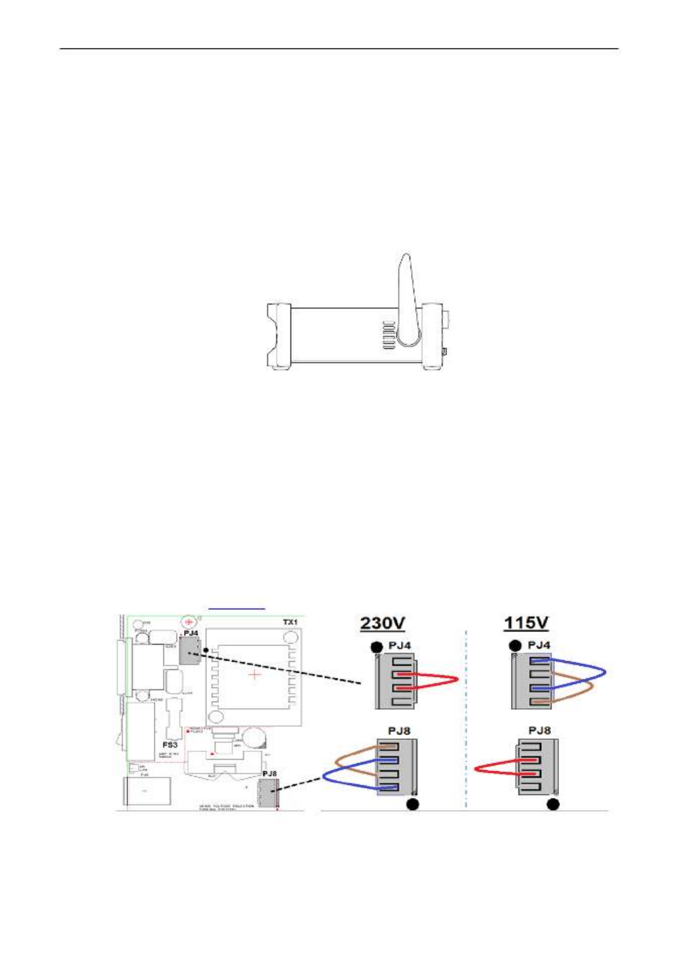
3 Installation
3.1 Mains Operating Voltage
Check that the instrument operating voltage marked on the rear panel is suitable for the local
supply. Should it be necessary to change the operating voltage, proceed as follows:
1. Warning! Disconnect the instrument from all voltage sources before beginning this
procedure.
2. Pull out both sides of the handle at the case pivot points, to free the position locking
pegs, and rotate the handle from the stowed position to the position shown below. Then
pull the sides of the handle outwards fully, one at a time, to remove the handle
completely.
3. Remove the two screws on the rear panel that retain the top cover and slide the top
cover towards the rear, with the soft bezel still in place, until it can be lifted clear.
Note: To avoid contaminating or damaging the PCB assembly, take care not to touch
any components other than the two shorting connectors described in the next step.
4. Remove the shorting connector in position PJ4 on the PCB beside the mains
transformer (TX1) and replace it with the alternative shorting connector from the
‘parking’ position PJ8; align pin1 of the connector with the pin 1 corner marker of the
header. ‘Park’ the unused connector on PJ8, see the diagrams below.
For 230V operation PJ4 should be fitted with the connector which has a single red wire
between its centre pins (pins 2 & 3).
For 115V operation PJ4 should be fitted with the connector which has a blue wire
between pins 1 & 3, and a brown wire between pins 2 & 4.
Note that the value of fuse FS3 (500mA) is the same for both AC voltage settings, see
Maintenance, section 13.
5. Reassemble in the reverse order.
6. To comply with safety standard requirements the operating voltage marked on the rear
panel must be changed to clearly show the new voltage setting.
Page 10
4.4.2 On/O operation without AC Power
With no AC power connected operation is from the internal rechargeable batteries and the ,
instrument is turned on or off by successive presses of the green button. The rear [ ] OPERATE
panel POWER switch has no function.
4.4.3 Power-up Settings
At power up the display briefly shows the installed software revision; strument is the in then restored
to the same measurement conditions as at power down including any advanced functions that were ,
running. However, if the instrument was showing a menu at power down, the menu will be
cancelled when powered up.
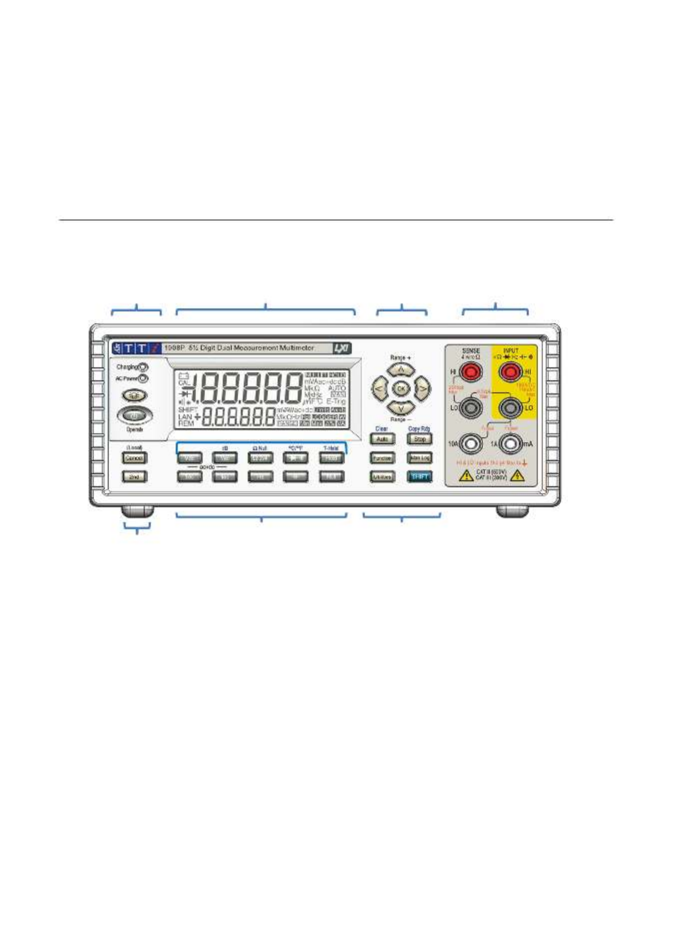
5 Measurement Connections
5.1 Input Sockets
The input sockets are 4mm safety sockets on a 19mm pitch designed to accept 4mm safety
plugs with fixed or retractable shrouds. All are rated to 1000Vpeak with respect to earth sockets
ground. between Safety will be maintained if voltages up to 1000Vpeak are accidentally applied
inappropriate terminals in excess of their marked ratings, but restoration of normal operation
may require replacement of protection devices (e.g. current range fuses).
The input impedance between is nominally 10M on dc ranges and INPUT HI and INPUT LO Ω
1M The Ω on ac ranges. The black socket is considered less positive than the red socket.LO
maximum voltage that can be applied between is 1000Vdc, 750VHI & LO rms (1000Vpeak).
The sockets are rated to 600V CAT II, 300V CAT III.
The and mA/10A current sockets are low impedance; the voltage burden between mA/10A LO
at full scale is < mA range and 100mA, 1A and 10A range100 10mV for the <600mV for the s.
The black socket is considered less positive than the white LO mA/ sockets. 10A The mA/ 1A
socket is protected with a 1.6A 1kV HRC fuse, and the socket with a 10A 1kV fuse; see 10A
Maintenance, section 14, for replacement details.
The SENSE HI & LO sockets are only used in 4 wire Ohms and RTD temperature -
measurements; refer to those sections for details. When used, the maximum differential
between and The SENSE LO INPUT LO should be < 0.5Vpeak. SENSE terminals are
protected against accidental connection of up to 200Vpeak between HI & LO.
Display
Measurement
t erminals
Measurement keys
Navigation
k eys
Function keys
Power
Function keys
Page 11
5.1.1 Multimeter Test Leads
The test leads supplied meet the requirements of and are rated to 1000V Cat IEC1010 031 -
III. Use only the test leads provided, or a set of similar performance, to ensure safe
operation. Alternative test leads should be rated to at least 1000V, 600V (Cat II) and 10A
current capability.
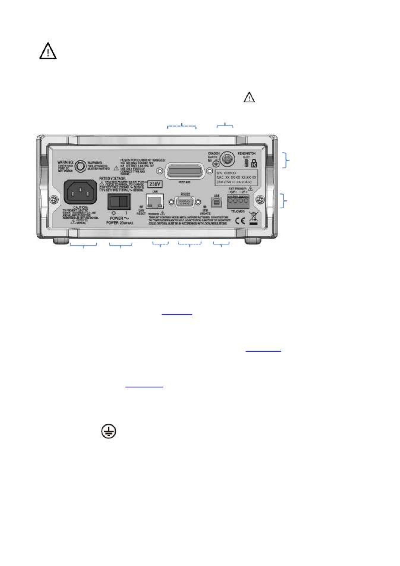
5.2 Rear Panel Connections
5.2.1 Trigger In/Out
Screw-less connectors are provided on the rear panel for connection of an external trigger the
signal See , and a trigger out signal. section 9 . for full details
5.2.2 Digital Interfaces
Depending upon model, rear panel connectors are provide ) ord (for USB only 1908 USB,
RS232, LAN and GPIB Refer to Remote Operation, (1908P). section 14, for full details.
5.2.3 AC Inlet
The instrument can be connected to AC mains using the power lead supplied or a suitable
alternative, see Installation section 3.2. When the power lead is connected this lead provides the
necessary protective earth connection to an external protective earth system.
5.2.4 Protective Earth Terminal
For battery only operation, without an AC power lead connected, the M4 threaded chassis
connection marked must be connected to an external protective earth system via a
green/yellow insulated cable, with a cross section of at least 0.75mm- 2, fitted with a M4 terminal.
Without this connection, ‘leakage’ current from any accessible part may exceed 0.5mArms, the
Normal (safe) limit specified by EN61010 under some-1, extreme measurement conditions, e.g. high
voltage, high frequency, AC volts measurement.
. WARNING! THIS INSTRUMENT MUST BE EARTHED.
TTL/CMOS
External Trigger
Warning! This instrument must be
earthed. Connect terminal to an external
protective earth system when instrument
is mains used without an AC connection.
Kensington
Lock
USB
RS232
LAN
Power
switch
AC power
c onnection
Protective
Conductor
Terminal
(1908P)
GPIB
(1908P
only)
Page 12
6 Making Basic Measurements
This section describes how basic measurements are made, i.e. single measurement mode
without post -processing of the results.
6.1 Scale Length
The scale length is ±120 00 for all measurements except (full scale 12,000) and ,0 frequency
capacitance (full scale 1200) is displayed when the range maximum is exceeded.. {OFL}
Note that, however, safety considerations and current that can be limit the maximum voltage
measured to below the scale length maximum.
6.2 Measurement Parameter Selection
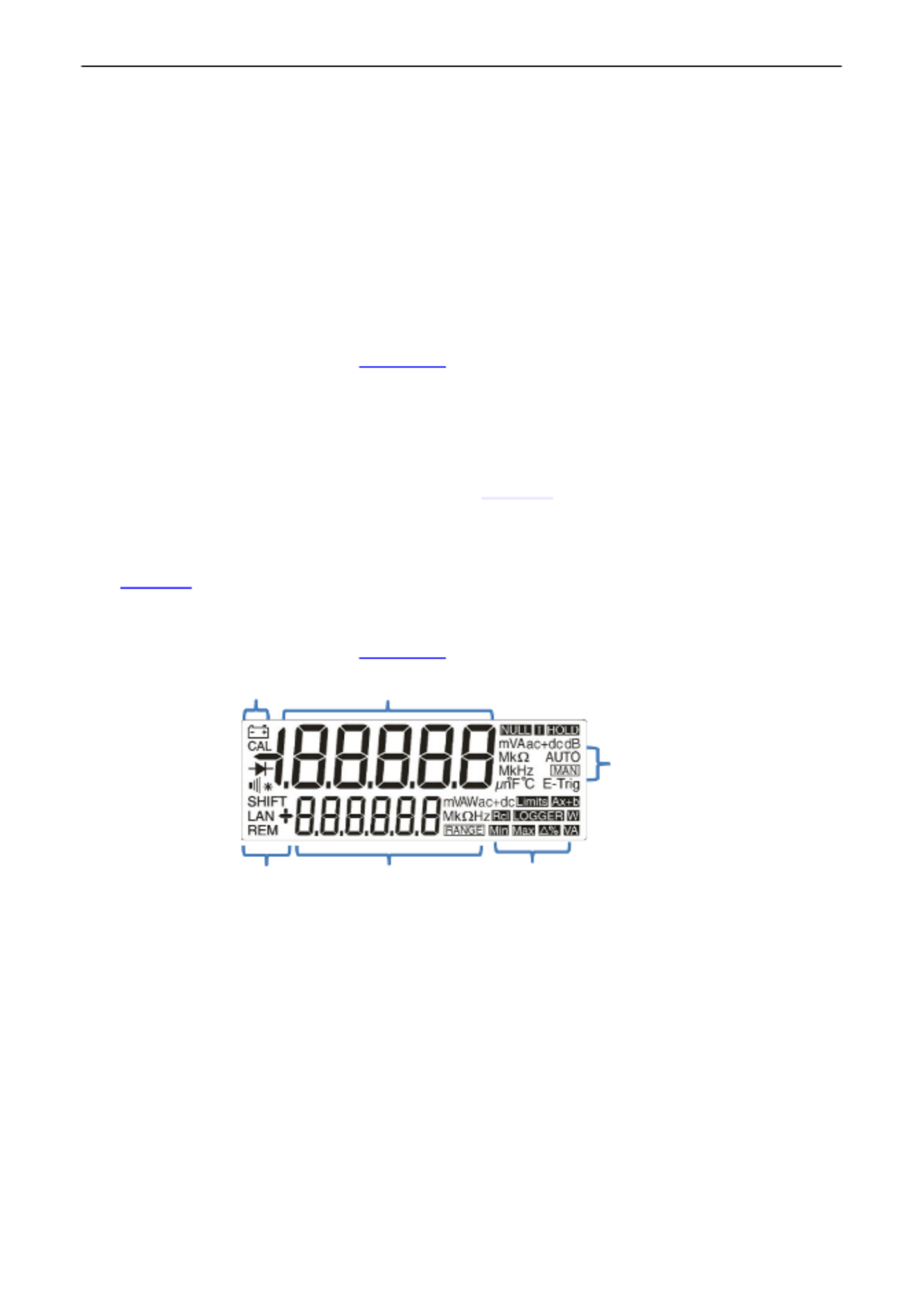
Refer to the front panel diagram in section 5.1
The two rows of darker grey keys below the display directly select the measurement
parameters for either the primary or secondary display. When pressed alone the parameter
keys select the parameter for the primary display, cancel any secondary measurement
functions auto range. , and set the range to -
Pressing [2 ]nd followed by a parameter key selects the parameter for the secondary display;
this is explained fully in Dual Measurement Mode, section 8, which also details the
combinations of parameters can be used. that
Additional parameters marked in blue above certain keys are selected by first pressing . [ ]SHIFT
Whilst shift is operational a ymbol appears on the left side of the{SHIFT} s display.
See section 7 . for full details
6.3 Measurement Range Selection
Refer to the front panel diagram in , and to the display diagram below
section 5.1 .
When a parameter is first selected, auto ranging is enabled and an symbol is - { }AUTO
displayed. Pressing either of the [ ] [v]ᴧ/ arrow keys (Range Range+/ -) -cancels auto ranging
whilst leaving the range set to its existing value. The and urther { }MAN symbol is displayed f
presses then change the range upwards or downwards. Pressing [ ] OK returns the instrument
to auto-ranging operation.
The units appropriate to the function and range are shown to the right of the (e.g. {mV ac})
display he . When the secondary display is not being used to show measurement values, t
selected range is shown there.
Note that the 10A range, which uses a different input socket from mA measurements, can only
be selected manually. Once 10A has been , however, this setting will be retained for selected
current measurement until it is returned to mA.
Note that the symbols apply only to the primary display.{ }AUTO and { }MAN
Primary measurement
Range or
2nd measurement
Functions
Remote
communications
Status
Range
Mode

Page 13
6.4 Making Voltage Measurements
Having selected Vdc or Vac, voltage measurements are made using the red INPUT HI socket
and the black within the yellow area of the panelINPUT LO socket . Five measurement ranges
(auto or manual) are available from 100mV to 1000V (dc) or 750V (ac).
The meter will show a minus sign (on dc measurements) when the voltage applied to the {-}
INPUT HI socket is more negative than that applied to the INPUT LO socket.
The maximum voltage that can be applied between is 1000V DC or 750V INPUT HI and LO
AC ; damage to the instrument may result if this limit is exceeded.
WARNING! The maximum input voltage to ground must not exceed 1000V . Safety will be peak
impaired if these ratings are exceeded, see Safety section at the beginning of the manual.
6.5 Making Current Measurements
Having selected Idc or Iac, current measurements up to 1.2A ( are made using the 1200.00mA)
white mA socket and the black INPUT LO socket; current measurements up to 10A are made
using the . The meter will show a minus sign 10A and socketLO s {-} (on dc measurements)
when the polarity of the current is such that it flows out of the rather than mA or 10A sockets
into it.
U socket 10sing the mA three measurement ranges (auto or manual) are available from mA to
10 0mA0 . Measurements up to 10A can be made using the 10A socket having manually ranged
to 10A with [ᴧ].
The 00mA10mA, 100mA and 10 ranges, using the mA socket, are protected by a 1.6A (F) HRC
fuse. The 10A range, using the 10A socket, is protected by a 10A (F) HRC fuse. Both fuses are
accessed via panel on the base of the instrumenta .
The input test leads and AC power lead must be disconnected before opening the fuse
access panel.
Note: After measuring high currents (i.e. above half scale) using the 1A or 10A ranges, thermal
voltages are generated that may create errors when making measurements on the most
sensitive dc voltage, current or Ohms ranges immediately afterwards. To ensure that the
specified accuracy is maintained, for the thermal effects to allow 10 minutes reduce before
making sensitive measurements.
6.6 Making Resistance Measurements
Pressing [Ω
Ω
Ω
ΩΩ ]2/4 Successive selects resistance measurement in either 2 wire or 4 wire mode.
presses alternate between the modes as indicated by {2W
Ω}
Ω}
Ω}
Ω}Ω} Ω}
Ω}
Ω}
Ω}Ω} {or 4W appearing briefly in the
secondary display measurement ranges (auto or manual) are available from 100. Six Ω to
10MΩ.
6.6.1 Two Wire Measurements
Normal (2 wire) resistance measurements are made using the INPUT HI and within LO sockets
the yellow area of the panel appropriate for higher resistance . This measurement mode is
measurements, and for lower resistance measurements where high precision is not required.
The see effects of test lead resistance can be removed using Null if required Ω – section 7.3.

Page 15
6.9 Making Capacitance Measurements
Pressing M[ ] selects capacitance measurement. easurements are made using the INPUT
HI and LO sockets within the yellow area of the panel. Five ranges (10nF to 100µF) are
available with 1200 count full scale giving resolutions of 10pF to 100nF respectively.
Zero calibration at the factory is carried out with no test leads connected; ideally, capacitors to
be measured should be connected directly to the sockets. Test leads, if used, should be kept as
short as possible to minimise stray capacitance but nevertheless a non zero reading will -
generally be present when the lowest ranges are selected. To eliminate this offset it is
recommended that the meter reading is nulled, once the range has been selected, with required
the test leads in their measurement positions but no capacitor connected.
It is also recommended that battery operation is used when making capacitance
measurements, to minimise reading jitter. Note that because the capacitor is discharged ,
between each measurement, the reading rate on the 100µF range is slower.
6.10 Over Voltage Protection
When making measurements of Resistance, Capacitance, Temperature, Continuity or Diode
checks an internal protection circuit protects the current source from source voltages applied to
the and INPUT HI LO sockets. If a voltage of greater than typically 10V is applied to the INPUT
HI and LO sockets the protection circuit will be engaged, the buzzer will sound and {trIP} will be
displayed. After completion of the trip event, t mode is set to Vdc to show the he measurement
over-voltage that is being applied to the input sockets. BIT 0 of the Input Trip Register (ITR) is
set to 1 (over voltage protect) see section 15.1.
6.11 Measurement Hold
Hold operates only on the primary display. causes the measurement to be Pressing [ ]Hold
frozen on the display along with a Provided that the meter is not in dual { } HOLD symbol.
measurement mode and not measuring capacitance, the normal, updated, reading will be
shown in the secondary display.
Hold only operates on the primary display, any measurement being shown on the secondary
display will continue to update normally.
Hold is cancelled by pressing or by changing range or function.[ ]Hold again,
6.12 Measurement Null
Null operates only on the primary display. Pressing [ ]Null causes the measurement to be
stored and subtracted from future readings locks the meter in the selected all . Pressing [ ]Null
range and shows Provided that the meter is not in dual { }NULL (and { }MAN ) symbols.
measurement mode and not measuring capacitance, the normal, un nulled, reading will be -
shown in the secondary display.
Null is cancel by pressing or by changing range or function.[ ]Null again,
6.13 The Cancel Key
[ ]Cancel can be used to return the mete It cancels dual r to a basic measurement mode.
measurement mode, dB, Null, Hold and T Hold, and any programmable functions including the -
Logger. It does not cancel Ω Null.
Consequently [Cancel] should not be used to cancel a single function, such as Hold, if other
functions need to be maintained.

Page 17
7.4 Temperature Measurement (
o
C/
o
F)
The instrument incorporates linearised measurements for PT100 and PT1000 platinum
resistance temperature detectors (RTDs).
The temperature function is selected by pressing the shifted function marked ° °F C/ [Shift]
[ ]. The default measurement is in degrees centigrade. To change to degrees fahrenheit
select the function again.
The default probe type is PT100. To change to PT1000 use [<] / [>].
The measurement and can use either a 2 wire or 4 wire connection, the latter using the HI LO
SENSE terminals in addition to the HI and LO INPUT terminals. The selection is made from the
Utilities menu – see section 12.7.
7.5 Touch and Hold (T Hold)
T- -Hold causes the meter to “hold” a reading on the display until a new non zero measurement
has been detected; this allows the user to touch probe the measurement point, remove- the
probes and read the meter afterwards. It is not available for Ohms, Continuity, or Diode Test
measurements.
T Hold is selected by the shifted key marked symbol is T- Hold [Shift] [Hold]. The {T- }HOLD
displayed, and each new reading is indicated by a beep sound. Measurement update is slow,
and small changes to the signal that occur after the probes have been connected will not be
shown.
Note that care should be taken when using T Hold with the most sensitive voltage ranges; when -
the probes are lifted from the circuit being measured, their high impedance means that stray
pick-up might generate another ‘valid’ reading and the true T Hold reading may be lost.-
T- -Hold operates only on the primary display in both manual and auto range modes; it is
cancelled by Hold again or by changing pressing T- [Shift] [Hold] the measurement parameter
or range.
7.6 Measurement Speed and Measurement Filter
The normal measurement speed is 4 readings/sec for most single measurement parameters.
For voltage, current and resistance measurements, the speed can be increased to 20
readings/sec at the expense of resolution which reduces to 12,000 counts. This is done from
the Utilities menu, see section 12.2.
In order to minimise jitter for sensitive measurements, an analogue filter is incorporated that
provides high rejection of 50Hz or 60Hz noise. Where the user requires quicker response to
signal changes, t filter can be switched off. This is particular relevant when the measurement he
speed is set to 20 readings/sec The filter is controlled from the Utilities menu, see . section
12.3.
7.7 Zero Re- Calibration
An automatic zero calibration of the basic DC measurement circuitry is performed every time
that the instrument is switched on. However, if the meter has been stored at a temperature
outside the specified operating range, and is switched on before it has fully acclimatised to the
working environment, accuracy may be affected as t ature changes. he meter’s temper To
ensure optimum accuracy, particularly on the 100mV and mA current ranges, zero calibration
can be repeated when the meter has acclimatised by using the Null key as follows:
Press [ ]Null and continue to hold it down until { }nULL shows in the main display (about 3
seconds later). continues to show whilst the auto zero is being performed (typically 5 { }nULL -
seconds); on completion the display returns to its previous mode.
Auto select -zeroing in this way cancels Null if this was already selected; press again to re[ ]Null -
if required.

Page 18
8 Dual Measurement Mode
In Dual Measurement mode a completely independent but complementary measurement can be
made and displayed on the secondary display. The two independent measurements are actually
made alternately, not simultaneously, and the display update rate for each measurement is
consequently reduced.
Note that this is not the same as dual display mode, where odified both a measurement and a m
version of that measurement are displayed, e.g. ac Volts and the dB equivalent n this case only a . I
single measurement is being made and the measurement rate is unchanged; further information is
given later in this section.
8.1 Dual Measurement Combinations
The full list is as follows: of dual measurement functions
Main Measurement
Secondary Measurement
Vdc
Vac, Idc, Iac
Vac
Vdc, Idc, Iac, Hz
Vdc + Vac
Vdc, Vac, Hz
dB
Vdc, Idc, Iac, Hz
Idc
Vdc, Vac, Iac
Iac
Vdc, Vac, Idc, Hz
Idc + Iac
Idc, Iac, Hz
Hz
Vac, Iac
The parameter for the secondary display is selected by pressing followed by the chosen [2nd]
measurement parameter. The secondary display parameter must be selected after the main
parameter has been set. Pressing an illegal parameter will cause a warning double beep and
the key entry will be ignored
Capacitance, Ω, and Continuity/Diode check cannot meaningfully be combined with other
measurements and are therefore always excluded from the secondary display. Vac+Vdc and
Iac+Idc are also excluded because they already involve dual measurements; when they are
being used no secondary display can be set.
The secondary measurement, with the exception of the 10A current ranges, always auto-
ranges. The 10A current ranges are set by firs the function ( d by t selecting [2 ]nd followe [ ]Iac or
[ ] [2Idc ) then pressing nd] followed by [ ] [2ᴧ. To measurementreturn to the mA select nd]
followed by . However, if both main and secondary displays are making current [v]
measurements, the range of the secondary measurement is always that of the main display.
If Vdc and Vac are the two measurement functions, auto ranging of the secondary display is -
restricted such that the dc measurement range is not lower than the ac range; this ensures that
the dc measurement is not affected by a high ac signal, see the ta n the Specification ble withi
section 19.
For example, if the main display is set to 10Vdc the secondary display can auto range between -
the 100mV, 1000mV and 10Vac ranges. In this example, low levels of ripple could be measured
(on the 100mV range) on a 10Vdc supply rail, but an ac input >12V will cause the secondary
display to warning the user to select a higher main display dc range such show Overload { }OFL
that the secondary ac measurement is in range. Similarly, if the main display is set to 100Vac
then the secondary display will not auto range below 100Vdc, even for small dc inputs.-
When frequency is selected for the secondary display the measurement is made using the ac
range set in the main display. This presents no problems if the main display is in auto range but -
if a higher range has been set manually, such that the reading is less than of the range 5%
maximum, the signal level may not be adequate for frequency measurement.
Page 19
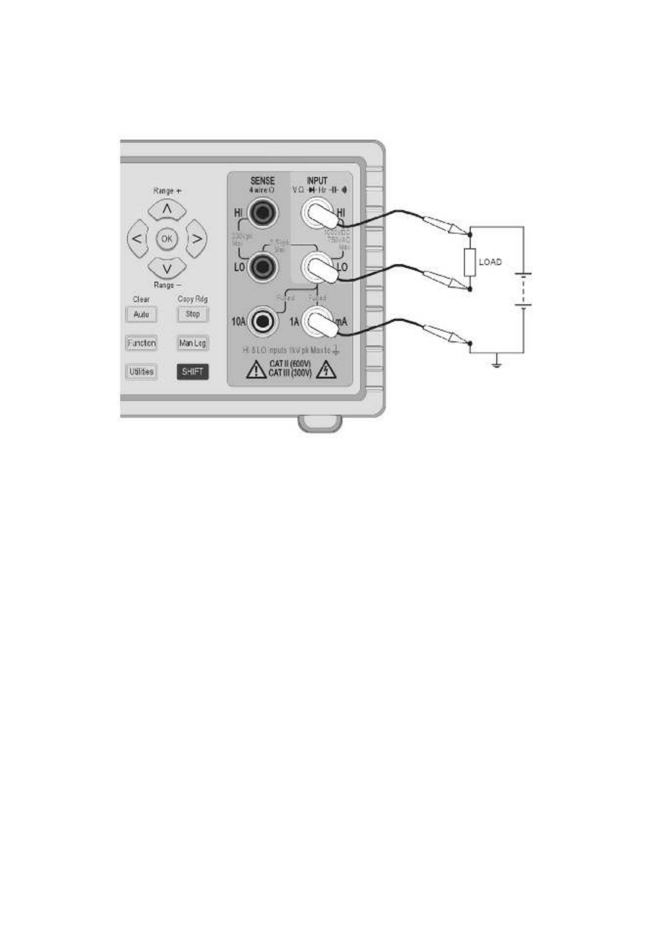
8.2 Making Voltage and Current Dual Measurements
Measuring ac and dc Volts, or ac Volts and frequency, etc. still only require two measurement
probes because both parameters of the dual measurement are made at the same physical
point. Simultaneous measurement of voltage and current on the same circuit will however
require a third connection, see the diagram:
Note that the voltage measured at the multimeter terminals is that across the load plus the
voltage drop in the common lead which is now carrying the whole circuit current. Even if the
resistance of the lead is very low, errors may arise at high currents and low voltages (i.e. low
load resistance) because the lead resistance becomes significant compared with the load.
8.3 Measurement Update Times
As discussed at the beginning of this section, the reading update rate is reduced in Dual
Measurement Mode because the two readings are made alternately. However, the reading rate
is not simply halved because enough time must be allowed for each measurement to fully settle
to the different conditions before the display is updated; unless this is done neither display will
reliably show the true measurement value. The settling time depends on the differences
between the main and secondary measurement range, function, and signal level; the delay is
longest when both displays show an ac measurement. Note that the settling times allowed
assume a steady state signal; varying signals or signals that exceed the range maximum, on
either measurement, will give unpredictable readings.
The following table summarises the measurement time (i.e. the time for the measurement to settle
and the display to be updated) for each parameter in all the permitted display combinations.

Page 20
Main
Secondary
Measurement Time
(4SPS)
Measurement Time
(20SPS)
Any Dual Function
None
.25s
.05s
Vac, dB, Iac
Hz*
.25s
.05s
Hz*
Vac, Iac
.25s
.05s
Vac, dB, Iac
Vdc, Idc
.5s
.1s
Vdc, Idc
Vac, Iac
.5s
.1s
Vac, dB
Iac
6s
3s
Iac
Vac
6s
3s
Vdc + Vac
Vdc, Vac, Hz
.5s
.1s
Idc + Iac
Idc, Iac, Hz
.5s
.1s
Measurement Time
(4SPS)
Measurement Time
(20SPS)
*Any Hz dual measurement
.25s
.125s
Frequency measurements have a fixed measurement time of 0.25s or 0.125s (gate time)
depending on the sample speed. This fixed measurement time only applies to the frequency
measurement, not the other dual measurement For example if the sample speed is set to fast .
(20SPS), the main measurement is Hz and the secondary measurement is VAC, then VAC will
be updated every 0.05s but the frequency measurement will only update every .125s.
9 Triggered Operation
A screw- . less connector on the rear panel provides both an input and output signal
9.1 Trigger In Signal
The trigger input ( connects to the LED of an opto isolator through a 1k- + I/P ) - Ω resistor.
Apply >+3V to set trigger input True; maximum safe applied 10V. input is +
The trigger input can be set to perform either of two actions, as set from the Utilities menu – see
section 12.4 .
1. Hold measurement the measurement in progress at the point that the input is set True –
is frozen on the display.
2. Log measurement – with the Logging function operating, the measurement in progress
at the point that the input is set True will be logged.
9.2 Trigger Out Signal (Measurement Complete)
The signal trigger out ( ) - O/P+ goes True each time n input trigger action is completed.a
The trigger out signal is an opto isolated open collector output with Low = True. The output -
conducts for 250ms input triggeron completion of an action.
The trigger output requires an external pull up (e.g. 4.7k- Ω ) to 5V and sinks typically 2mA
maximum maximum safe off when True; -state voltage is +10V.

Page 22
To select Ax + b, press [Function] { } and use the Navigator keys to choose Ax+b as the
flashing symbol. the secondary display will flash the word Confirm ; with [ ]OK {run}.
To view or edit the A or b values, press to select and confirm with[<] or [>] {Edit} . [ ]OK The
existing A value will be displayed and can be changed using the Navigator keys ([<] / [>] to
select the digit and to change the value) Once the value is confirmed with the [ᴧ] /[v] . is set, it
[ ]OK , after which the b value can be viewed and edited in the same way.
Once the b value has been set and the display will return to flashing the confirmed , with [OK]
word {run}. Pressing [OK] at this point will start the function running.
A is variable from 0.0001 to ±9 with the decimal point in a fixed posit on after the ±0 9.9999, i
second 1.0000, digit; the default value is +0 which can be restored by pressing shifted key Clear
[Shift] [Auto]. T he A value is retained for any range and any measurement parameter until
changed using Edit.
b 0 9is a floating point number variable over the range ±0 0000 to ±9 9999 with the decimal point
and units set by the range selected during editing. Pressing the shifted key Clear [Shift] [Auto]
enters the default value of +000000; pressing the shifted key Copy Rdg [Shift] [Stop] enters
the current reading as the value.
The b value is retained for any range and any measurement parameter until is selected {Edit}
again. At that point the displayed value, which may be truncated or under flowed by the -
limitations of the display with a changed decimal point position, becomes the stored number.
10.4 Min- Max
The Min Max function stores the maximum (most positive) and minimum (most negative) values -
that occur when the function is run and displays in the secondary display simultaneously , either
with the normal measurement in the main display.
To select Min and use the Navigator keys to choose as the - Max, press [ ]Function {Min Max}
flashing symbols. Confirm with the secondary display will flash the word[OK]; {run}.
When running the maximum reading will be shown on the secondary display initially with the
{ }Max . Press symbol displayed [<] Press to view the Min value. [<] or [>] to alternate between
displaying the maximum and minimum values.
Min and Max are stored as floating point numbers and the can be operated with the function
meter changing ranges either manually or by auto-range.
After leaving the function, the values remain stored and can be viewed at any time. To do this
re- - select Min Max as the function and use the navigator keys to select {rECALL}. Confirm with
[OK] and use [<] [>] and to alternate between the two values which are shown on the primary
display.
Pressing the shifted key Clear with either Max or Min displayed will reset it.[Shift] [Auto]
10.5 Delta %
The Delta % function displays the percentage deviation of the measurement from a reference
value in the secondary display. The main display shows the normal reading.
Delta % = - % Reading Reference
Reference
The Delta % maximum display is ±999.99% and the resolution is fixed at 0.01%. The display
shows {–Or–} - (over range) if the maximum is exceeded.
To select Delta %, press [Function] { %} and use the Navigator keys to choose Δ as the
flashing symbol. Confirm with ; the secondary display will flash the word [OK] {run}.
To view or edit the reference value, press the Navigator to select [<] / [>] {Edit}
and confirm
with [OK]. The reference value will be displayed and can be changed using the Navigator keys
( / [<] / [>] to select the digit and [ ᴧ] [v] to change the value). Once the value is set and

Page 23
confirmed with [OK], the display will return to at this point will start the . {run} Pressing [OK]
function running.
The reference value is can be number variable over the range 0 to ±9999±00000 99; the
decimal point position is set by the range in use during edit. The reference default value of
10000 ear (decimal point determined by range) can be entered by pressing the shifted key Cl
[Shift] [Auto]. The latest meter reading can be entered by pressing the shifted key Copy Rdg
[Shift ]] [Stop .
10.6 Watts
The Watts function calculates power using the formula
Watts = V2/R
It can only be run when Vdc or Vac are selected in the main display. The reference impedance
can be set anywhere between and 999990.1 .9 Ohms.
To select Watts, press [Function] and use the Navigator keys to choose {W} as the flashing
symbol. Confirm with ; the secondary display will flash the word [OK] {run}.
To view or edit the reference value, press the Navigator Left or Right key to select {Edit} and
confirm with . The reference value will be displayed and can be changed using the [OK]
Navigator keys to select the digit and to change the value). Once the value is ( [<] / [>] [ᴧ] /[v]
set confirmed with , the display will return to at this point will start the [OK] {run}. Pressing [OK]
function running.
10.7 VA
The VA function calculates power by multiplying voltage and current readings. The meter must
be connected for both voltage and current measurement, see Making Voltage and Current Dual
Measurements, section 8.2, with Vdc or Vac selected for the main display.
To select VA, press [Function] and use the Navigator keys to choose { }VA as the flashing
symbol. Confirm with ; the secondary display will flash the word [OK] {run}. Pressing [OK]
again will start the function running.
11 Data Logging
The logger function can store up to volatile memory. 500 readings from the main display in non-
The store is linear, with around. Readings are triggered by either the internal timer, no -wrap
manual key press, external trigger command. Readings input True, interface ( ) -I/P+ or remote
are stored as point numbers with their units and reading number but without any form of floating-
time stamping.
11.1 Setting- up the Logger
To select the Logger, press [Function] and use the Navigator keys to choose {LOGGER} as
the flashing symbol. Confirm with ; the secondary display will flash the word [OK] {run}.
Use the Navigator keys to select and confirm with . The primary display will show{Edit} [OK]
{PEr} (Period) with the secondary display showing the existing setting (default value = Off)
{OFF}.
Manual or External Triggered Logging (O)
With the period set to , the timer is inoperative and reading are stored only in response to {O} s
the Man Log key, the Ext Trigger, or a Remote Interface command. To return to {O} from
another setting press the shifted key Clear [Shift] [Auto]. Confirm with [OK].
To log from the external trigger input, the Trigger function must be set accordingly External –
see section 12.4.

Page 24
Logging Every reading (All)
With the period , the timer is inoperative and readings are stored after every set to All {ALL}
measurement, i.e. at the measurement rate of 4 readings/sec or 20 readings/sec dependant on
mode and measurement speed setting. To select All, first set the period to Off (using the shifted
key Clear [Shift] [Auto]) and press [v]. Confirm with [OK].
Logging from the Timer
To engage the timer starting from Off or All, press the Navigator Up key once or twice
respectively. The display will show 0001 representing a timer period of 1 se This can be cond.
changed to any value up to 9999 seconds using the Navigator keys to select the digit ( [<] / [>]
and [ᴧ] /[v] to change the value) Confirm with . [OK].
Multiple Trigger Sources
A reading is logged in response to any valid trigger source. Thus, for example, the timer can be
set to log at fixed intervals and additional intermediate readings logged by pressing
[Man Log], or generating an external trigger command.
11.2 Running the Logger
Once the logger has been set up as described above, confirmation of the period will return the
secondary display to flashing the word . Pressing at this point will start the logger {run} [OK]
running.
The reading number is shown in the secondary display (00 to 499). When the maximum 1
number of readings is reached the display shows If the logger has existing readings { }FULL .
stored, new reading will commence at the next available store number.s
Note that all logging sources are OR’ed so that, the timer (if active), manual logging key, trigger
input, or remote interface command can all cause a measurement to be stored.
11.3 Starting and Stopping the Logger
Logging can be paused by pressing . This returns the display to show a flashing[Stop] {run}
and logging can be resumed by pressing logger Edit, Recall or Clear can be [OK]. Alternatively
selected at this point.
When paused, no measurements and no change to the measurement parameter or range, can ,
be made. To make changes or view the measurement without logging, the function must be
exited by pressing [Function]. Logging can be restarted by pressing and then [Function]
pressing [OK] twice.
11.4 Recalling Logger Readings
Logger readings are held in non volatile memory until cleared, and can be viewed at any time. -
To recall readings to the display, select the logger function and use the Navigator key to select s
{rECALL}. Confirm with [OK].
The last viewed logger position is shown in the secondary display with the associated
measurement reading in the main display. Use the Navigator keys to scroll through the
readings.
11.5 Clearing Logger Readings
To clear the contents of the logger, select the logger function and use the Navigator keys to
select {CLEAr}. Confirm with . The secondary display will show[OK] {nOnE} and all logger
entries will be cleared. It is not possible to clear individual logger entries.
Once cleared, the logger will commence when run.from position 000

Page 26
12.7 Temperature Probe Setup {rtd}
The temperature be set to use a measurement function can two wire {2W} or four wire {4W}
connection the and - the latter using the in addition to SENSE sockets HI LO INPUT sockets .
The default value is four wire {4 W}.
12.8 Set Factory Defaults {rESEt}
The instrument can be returned to factory defaults. This will return all values to their defaults
and clear any stored data.
When [OK] is pressed, the display will show Accept? {ACCEPt}. The reset is performed when
[OK] is pressed again. Alternatively use the navigator keys to select Cancel {CAnCEL} and
press [OK] to exit the reset function.
12.9 Switch Off on AC Power disconnection {AC OFF}
The action of the instrument when AC power is disconnected can be changed. Three options
are available: Normal {OFF}, Auto {AUtO} or Battery {bAtt}.
For the default condition, set to NormalAC OFF {OFF}, the instrument is restored to its
previous state prior to power down (on or standby) when AC power is applied and turned off
w hen the AC power is disconnected.
There are situations where the instrument should remain on (operating under battery power)
when the AC power is disconnected when logging readings over an extended period; for , e.g.
these, the Auto or Battery settings will be more appropriate.
With AC OFF set to Auto {AUtO},the instrument is restored to its previous state prior to power
down (on or standby) when AC power is applied action when AC power is disconnected but the
depends upon how the instrument was turned on. If the instrument was turned on by
connection of AC power, removing the AC power will turn it off (as in the default condition).
However, if the instrument was turned on from battery power, removing the AC power will not
turn it off.
With AC OFF set to Battery {bAtt},connecting or disconnecting the AC power does not turn the
instrument on or off.
12.10 Measurement Update Symbol {S At r}
The measurement update is shown by a flashing asterisk the left side of { * } (star) symbol on
the display. The symbol becomes conti If required the symbol nuous in fast measurement mode.
can be turned Off. The default condition is On { }On .
12.11 GPIB Address {Addr}
The GPIB address can be set between 0 a The default address is 1nd 31. .
Page 29
14 Remote Operation
The 1908P model can be remotely controlled via its RS232, USB, GPIB or LAN interfaces. The
1908 (non ‘P’) can only be controlled via USB. In order to remotely control the instrument via
RS232, GPIB or LAN, mains power must be applied. USB however can function with or without
mains power applied as it is host powered. As such the USB interface can be used when powered
from the batteries.
The GPIB interface provides full facilities as described in IEEE Std. 488 parts 1 and 2.
The RS232 interface communicates directly with a standard COM port.
The USB interface enumerates as a Communications Class device and interacts with application
software through a standard virtual COM port device driver on the PC. The instrument firmware can
be updated in the field via the USB port; see the ‘Maintenance section ’ for details.
The LAN interface is designed to meet LXI (Lan eXtensions for Instrumentation) version
1.4 2011. LXI Core Remote control using the LAN interface is possible using the TCP/IP Sockets
protocol. The instrument also contains a basic Web server which provides information on the unit
and allows it to be configured from a web browser. Simple command line control from the browser
is also possible.
14.1 GPIB Interface
The standard GPIB interface 24 way connector is located on the instrument rear panel. The pin -
connections are as specified in IEEE Std. 488.1 1987 and the instrument complies with both IEEE -
Std. 488.1 1987 and IEEE Std. 488.2- -1987.
It provides full talker, listener, service request, serial poll and parallel poll capabilities. There are no
device trigger or controller capabilities. The IEEE Std.488.1 interface subsets provided are:
SH1, AH1, T6, L4, SR1, RL2, PP1, DC1, DT0, C0, E2.
The GPIB address of the unit is set from the front panel: select the { }Utilities menu then { }Addr .
The present GPIB address is displayed. If it needs to be changed, use the Navigator keys to set the
desired address and then press [OK].
The interface will operate with any commercial GPIB interface card, using the device drivers and
support software provided by the manufacturer of that card.
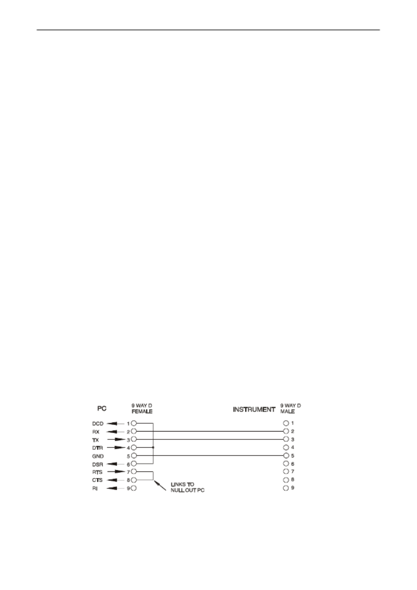
14.2 RS232 Interface
The 9- -way D type serial interface connector is located on the instrument rear panel. It should be
connected to a standard PC port preferably using a fully wired 9 way 1:1 male female cable without - -
any cross over connections. Alternatively, a 3 way cable can be used, connecting only pins 2, 3 - -
and 5 to the PC, but with links made in the connector at the PC end between pins 1, 4 and 6 and
between pins 7 and 8, as shown in the diagram:
Most commercial cables provide these connections.
In addition to the transmit and receive data lines, the instrument passively asserts pins 1 (DCD) and
6 (DSR), actively drives pin 8 (CTS) and monitors pin 4 (DTR) from the PC. This allows the use of a
fully wired 9- way cable.

Page 32
14.4.6 LXI Discovery Tool
This tool can be used to display the IP addresses and other associated information of all connected
devices that comply with the VXI 11 discovery protocol. It is a Windows PC application,- which is
provided on the supplied CD that can be installed and run on the controlling PC, with the unit -ROM,
either connected directly to the PC network connector or via a router. Double clicking on any entry in
the list of discovered devices will open the PC's web browser and display the Home page of that
device. For a later version of the tool that supports discovery by both VXI 11 and mDNS visit -
www.lxistandard.org . There are also tools for LAN discovery included as part of the National
Instruments Measurement and Automation Explorer package and the Agilent Vee application.
14.4.7 VXI-11 Discovery Protocol
The instrument has very limited support of VXI 11 which is sufficient for the discovery protocol and -
no more.
It implements a Sun RPC Port mapper on TCP port 111 and UDP port 111 as defined in RFC1183. -
The calls supported are:
NULL, GET PORT and DUMP.
On TCP port 1024 a very simple VXI 11 protocol is implemented, sufficient only for instrument -
discovery. This implements the following calls:
CREATE LINK, DEVICE_WRITE, DEVICE_READ and DESTROY_LINK.
Once a link has been created anything written to the device is ignored and any attempt to read from
the device returns the same identification string as the *IDN? query.
14.4.8 VISA Resource Name
Because of the limited support for VXI 11 (Discovery Protocol only), the instrument must be referred -
to by its raw socket information when used with software packages which communicate using a
VISA resource name. For example, an instrument at IP address 192.168.0.100 would normally have
a VISA resource name of "TCPIP0::192.168.0.100::inst0::INSTR" but for this instrument the name
must be modified to read "TCPIP0::192.168.0.100::9221::SOCKET" where 9221 is the TCP port
used by this instrument for control and monitoring, see below.
14.4.9 XML Identication Document URL
As required by the LXI standard, the instrument provides an XML identification document that can
be queried via a GET at “http://IPaddress:80/lxi/identification” that conforms to the LXI XSD Schema
(available at http://www.lxistandard.org/InstrumentIdentification/1.0 ) and the W3C XML Schema
Standards ( ). This document describes the instrument. The
http://www.w3.org/XML/Schema
hostname can be used instead of the IP address if name resolution is working.
14.4.10 TCP Sockets
The instrument uses 1 socket on TCP port 9221 for instrument control and monitoring. Text
commands are sent to this port as defined in ‘Remote Commands’ and any replies are returned via
the same port. Any command contain string must one or more complete commands. Multiple
commands may be separated with either semicolons “;” or line feeds. No terminator is requiredfinal ,
since the TCP frame implies a terminator, but one may be sent if desired .
15 Status Reporting
The standard status and error reporting model described in IEEE Std. 488.2 was designed for the
GPIB interface and contains some features intended for use with the Service Request and Parallel
Poll hardware capabilities of that interface, and to accommodat duplex operation. Although e its semi-
those facilities are of little use with other interfaces, this instrument makes the full set of capabilities
available to all of the interfaces. All the remote interfaces share the same set of status and error
registers.
The full set of error and status registers and the individual bits they contain is shown in the Status
Model Diagram and described in detail below, but in brief the status is maintained using three
primary registers the Input Trip Register, the Standard Event Status Register and the Execution

Page 33
Error register. A summary is reported in the Status Byte Register, as selected by two masking
registers – the Input Trip Enable register and the Standard Event Status Enable Register. Two
further mask registers, the Service Request Enable register and the Parallel Poll Response Enable
register, control operation of the GPIB hardware Service Request and Parallel Poll (and the
associated ist message) respectively. It is recommended that, when controlling the unit thro ugh any
interface other than GPIB, the controller program should simply read the primary status registers
directly.
The instrument specific Input Trip Registers record events related to the electrical function of the
multimeter and the user inputs applied.
The Standard Event Status Register, supported by the Execution Error and Query Error registers,
records events concerned with command parsing and execution, and the flow of commands,
queries and responses across the interface. These are mainly of use during software development,
as a production test procedure should never generate any of these errors.
15.1 Input Trip Registers (ITR & ITE).
The Input Trip Register reports electrical conditions that have arisen during the operation of the
multimeter. By its nature it is common to all interfaces. It reports events that have resulted in the unit
unexpectedly disabling the internal current source and reverting the primary measurement to Vdc.
The Input Trip Register has a summary bit in the Status Byte Register, with an associated Enable
Register to determine which, if any, bits contribute to that summary. All these registers are bit fields,
where each bit is independent (so more than one may be set simultaneously) and has the
significance detailed below.
15.1.1 Input Trip Register (ITR)
Bits 7-1
Not used, permanently 0.
Bit 0 Over Voltage Protect: Set when an overvoltage is applied between the HI and LO
terminals in the following modes Ohms (4 wire and 2 wire), Diode, Continuity, –
Capacitance and Temperature measurement.
The bits in the Input Trip register are set when the event they report occurs, and then remain set
until read by the ITR? query. After the Response Message is sent any bits reporting conditions that
no longer apply will be cleared; any bit reporting a condition that remains true will remain set.
The Input Trip Enable Register provides the mask between the Input Trip Register and the Status
Byte Register. If any bit becomes ‘1’ in both registers, then the INTR bit (bit 1) will be set in the
Status Byte Register. This enable register is set by the ITE <NRF> - command to a value 0 255, and
read back by the ITE? query (which will always return the value last set by the controller). On
power-up the ITE register is set to 0 and ITR is cleared (but bits it contains may be set after
initialisation in the unusual case of any of the conditions reported being true).
15.2 Standard Event Status Registers (ESR and ESE)
The Standard Event Status Register is defined by the IEEE Std. 488.2 GPIB standard. It is a bit
field, where each bit is independent and has the following significance:
Bit 7
Power On. Set once the instrument is fully initialised and operating after either
power up from the application of mains, or when the key is pressed in [Operate]
standby. It is also set when first powered up on batteries although this is only useful
on USB as all other remote interfaces are not available under battery power.
Bits 6, 3 & 1: Not used, permanently 0.
Bit 5 Command Error. Set when a syntax error is detected in a command or parameter.
The parser is reset and parsing continues at the next byte in the input stream.
Bit 4 Execution Error. Set when a non zero value is written to the Execution Error -
register, if a syntactically correct command cannot be executed for any reason.
Bit 2
Query Error.
Set when a query error occurs, because the controller has not issued
commands and read response messages in the correct sequence.
Bit 0
Operation Complete. Set in response to the ‘*OPC’ command.

Page 38
16.1.4 Command Timing
There are no dependent parameters, coupled parameters, overlapping commands, expression
program data elements or compound command program headers.
All commands are separate and sequential, and are executed when parsed and immediately
considered complete. To provide useful functionality, the Operation Complete bit (bit 0) in the
Standard Event Status Register is only ever set by the *OPC command. Either the *OPC command
or the *OPC? query can be used for device synchronisation due to the sequential nature of remote
operations.
16.1.5 Response Formats
Responses from the instrument to the controller are sent as <RESPONSE MESSAGES>, which consist
of one <RESPONSE MESSAGE UNIT> followed by a <RESPONSE MESSAGE TERMINATOR>, which is the
carriage return character (0DH ) followed by the new line character (0A H) with, in the case of GPIB
only, the END END message NL^ . This is shown as in the descriptions below.<RMT>
Each query produces a specific which is described in the entry for the query <RESPONSE MESSAGE>
command in the remote commands list below. Most responses consist of a keyword followed by
either text or a number in one of the following formats:
<NR1> An integer without a decimal point or a unit.
<NR2> A fixed point number with a fractional part but no exponent part.
<NR3> A floating point number with both a fractional part and an exponent part.
<CRD> Character Response Data, consisting of the text characters listed.
<ASCII data> A combination of numbers and text characters.
When helpful, numbers are followed by a units indication (which depends on the present
measurement mode) to provide confirmation. The units used are: V DC, V AC, V AC+DC, A DC,
A AC, A AC+DC, Hz, Ohms, F (Farads), V, dB, W, VA, %, F (Fahrenheit) and C (Celsius).

Page 39
16.2 Command List
This section lists all the commands and queries implemented in this instrument. All numeric
parameters are shown as <NRF> <NR1> <NR2> <NR3> and may be sent as , or as described above.
16.2.1 General Commands
READ?
Returns the next reading from the main display immediately after the
command has been parsed.
The syntax of the response is: <ASCII data><RMT>
Where <ASCII data> is a character string -divided into 11 character plus up to
8-character fields. The first field is the measurement value and consists of
the following:
Digit 1: space (for positive values) or a minus sign.
Digits 2 to 8: a 6 digit number plus decimal point in the format of the range
selected for the measurement.
Digits 9 to 11: the exponent in the form e00, e 3, e03, etc., i.e. engineering -
units.
Any overload reading (i.e. > 120,000 counts) is returned as ‘OVLOAD’. A
calculation overflow (relevant to some function results) is returned as
‘OVFLOW’.
The second field is the unit indication and will be one of the following:
V DC
V AC
V AC+DC
A DC
A AC
A AC+DC
Hz
Ohms
F (Farads)
V (Diode test)
C (Celsius)
F (Fahrenheit)
dB
W
VA
%
Examples:
101.234e (101.234mV)-3 V DC
- - 10.0012e00 V DC ( 10.0012V)
00.1234e00 V AC+DC (0.1234V)
100.01e03 Hz (100.01kHz)
01.010e-6 F (1.01µ F)
READ2?
Returns the readings from the secondary display immediately after the
command has been parsed. Then syntax is as for READ? Described above.
If the secondary display is currently showing the range of the main (primary)
display the response will be RANGE.
MODE?
Returns the state of the main display, including the mode, range and
whether the range is locked (manual) or autoranging.
The syntax of the response is: <ASCII data>,<ASCII data>, , <ASCII data> <RMT>
The response includes three ASCII data fields.
The first field contains the primary display Mode which includes:
VDC, VAC, V AC+DC, IDC, IAC, IAC+DC, OHMS, DIODE, CONT, FREQ,
CAP, TEMPC, TEMPF.
The second field contains the range e.g. 1000mV.
The third and final field contains the range selection state either ‘MAN’ for
manual range, or ‘AUTO’ for autoranging.
Each of the ASCII fields is separated by a comma.

Page 40
MODE2?
Returns the state of the secondary display, including the mode, range and
whether the range is locked (manual) or autoranging.
The syntax of the response is: <ASCII data> <ASCII data>, ,<ASCII data> , <RMT>
The response includes three ASCII data fields.
The first field contains the secondary display Mode which includes:
VDC, VAC, IDC, IAC, FREQ.
The second field contains the range e.g. 1000mV.
The third and final field contains the range selection state either ‘MAN’ for
manual range, or ‘AUTO’ for autoranging. Manual range selection is only
available when selecting the 10A range.
Each of the ASCII fields is separated by a comma.
FILTON
Enables the 50/60Hz hardware filter. This filter only affects the Vdc and
Ohms measurement modes.
FILTOFF
Disables the 50/60Hz hardware filter. This filter only affects the Vdc and
Ohms measurement modes.
SPEED
<CPD>
Sets the standard sampling speed of the instrument to either 4SPS or
20SPS.
The following <CPD> can be used to set the sampling speed:
<SLOW> sets the sampling speed to 4SPS.
<FAST> sets the sampling speed to 20SPS.
RTD
<CPD>
Sets the RTD temperature measurement connection to either 2 wire or 4
wire. The following can be used to set the connection:<CPD>
<2W> sets the measurement connection to 2 wire.
<4W> sets the measurement connection to 4 wire.
16.2.2 Main Display Commands
VDC
<CPD>
Sets the main display to dc Volts and optionally sets the range; if no range is
specified the display defaults to autorange.
The following <CPD> can be used to set the range:
<100MV>,<1000MV>,<10V>,<100V>,<1000V>
VAC
<CPD>
Sets the main display to ac Volts and optionally sets the range; if no range
is specified the display defaults to autorange.
The following <CPD> can be used to set the range:
<100MV>,<1000MV>,<10V>,<100V>,<750V>
VACDC
<CPD>
Sets the main display to ac+dc Volts and optionally sets the range; if no
range is specified the display defaults to autorange.
The following <CPD> can be used to set the range:
<100MV>,<1000MV>,<10V>,<100V>,<750V>
IDC
<CPD>
Sets the main display to dc Amps and optionally sets the range; if no range
is specified the display defaults to mA autorange.
The following <CPD> can be used to set the range:
<1MA>,<100MA>,<1000MA>,<10A>

Page 41
IAC
<CPD>
Sets the main display to ac Amps and optionally sets the range; if no range
is specified the display defaults to mA autorange.
The following <CPD> can be used to set the range:
<1MA>,<100MA>,<1000MA>,<10A>
IACDC
<CPD>
Sets the main display to ac+dc Amps and optionally sets the range; if no
range is specified the display defaults to mA autorange.
The following <CPD> can be used to set the range:
<1MA>,<100MA>,<1000MA>,<10A>
OHMS
<CPD>
Sets the main display to two wire Ohms and optionally sets the range; if no
range is specified the display defaults to autorange.
The following <CPD> can be used to set the range:
<100>,<1000>,<10K>,<100K>,<1000K>,<10M>
2WOHMS
<CPD>
Sets the main display to two wire Ohms and optionally sets the range; if no
range is specified the display defaults to autorange.
The following <CPD> can be used to set the range:
<100>,<1000>,<10K>,<100K>,<1000K>,<10M>
4WOHMS
<CPD>
Sets the main display to four wire Ohms and optionally sets the range; if no
range is specified the display defaults to autorange.
The following <CPD> can be used to set the range:
<100>,<1000>,<10K>,<100K>,<1000K>,<10M>
CONT
Sets the main display to continuity test.
DIODE
Sets the main display to diode test.
TEMPC
<CPD>
Sets the main display to temperature measurement and optionally Celsius
sets the RTD probe type; if no probe is specified the existing probe is used.
The following <CPD> can be used to set the RTD probe type:
<PT100>,<PT1000>
TEMPF
<CPD>
Sets the main display to Fahrenheit temperature measurement and
optionally sets the RTD probe type; if no probe is specified the existing
probe is used.
The following <CPD> can be used to set the RTD probe type:
<PT100>,<PT1000>
CAP
<CPD>
Sets the main display to Capacitance and optionally sets the range; if no
range is specified the display defaults to autorange.
The following <CPD> can be used to set the range:
<10NF>,<100NF>,<1UF>,<10UF>,<100UF>
FREQ
<CPD>
Sets the main display to Frequency and optionally sets the range; if no
range is specified the display defaults to autorange.
The following <CPD> can be used to set the range:
<100HZ>,<1000HZ>,<10KHZ>,<100KHZ>
AUTO
Sets the main display to autorange, except for Continuity or Diode check.
MAN
Sets the main display to manual, i.e. the current range is ‘locked’.
Specyfikacje produktu
| Marka: | Aim TTi |
| Kategoria: | multimetr |
| Model: | 1908 |
Potrzebujesz pomocy?
Jeśli potrzebujesz pomocy z Aim TTi 1908, zadaj pytanie poniżej, a inni użytkownicy Ci odpowiedzą
Instrukcje multimetr Aim TTi

15 Maja 2024
Instrukcje multimetr
- multimetr PeakTech
- multimetr Joy-It
- multimetr Voltcraft
- multimetr Milwaukee
- multimetr Yato
- multimetr Parkside
- multimetr GW Instek
- multimetr Stanley
- multimetr Silverline
- multimetr Testo
- multimetr TFA
- multimetr Chauvin Arnoux
- multimetr Gembird
- multimetr Uni-T
- multimetr Owon
- multimetr Biltema
- multimetr Digitus
- multimetr Vimar
- multimetr Schneider
- multimetr Emos
- multimetr Sonel
- multimetr BaseTech
- multimetr Perel
- multimetr Trotec
- multimetr Velleman
- multimetr Pyle
- multimetr Gossen Metrawatt
- multimetr Fluke
- multimetr Megger
- multimetr Weidmüller
- multimetr BENNING
- multimetr Brandson
- multimetr Metrix
- multimetr Rigol
- multimetr Abus
- multimetr Elro
- multimetr Ferm
- multimetr Hager
- multimetr Extech
- multimetr Testboy
- multimetr Kyoritsu
- multimetr Klein Tools
- multimetr Powerfix
- multimetr Workzone
- multimetr Alecto
- multimetr JUNG
- multimetr Monacor
- multimetr Etekcity
- multimetr Wiha
- multimetr HT Instruments
- multimetr Qian
- multimetr Beha-Amprobe
- multimetr Clas Ohlson
- multimetr Laserliner
- multimetr Proline
- multimetr Ideal
- multimetr Profile
- multimetr Aldi
- multimetr Appa
- multimetr Amprobe
- multimetr Amiko
- multimetr Brennenstuhl
- multimetr Tacklife
- multimetr Somogyi
- multimetr Steren
- multimetr Flir
- multimetr Maxwell
- multimetr Topcraft
- multimetr Altai
- multimetr Plieger
- multimetr Projecta
- multimetr Cablexpert
- multimetr Greenlee
- multimetr Högert
- multimetr Wago
- multimetr REV
- multimetr Bruder Mannesmann
- multimetr Keithley
- multimetr Bearware
- multimetr Metrel
- multimetr Multimetrix
- multimetr Digi-tool
- multimetr Skandia
- multimetr Elma
- multimetr Testec
- multimetr Hubinont
- multimetr Kewtech
- multimetr Strex
- multimetr Mastech
- multimetr MBS
- multimetr MGL Avionics
- multimetr PCE Instruments
- multimetr Micronta
- multimetr CEM
- multimetr Horex
- multimetr Cosinus
- multimetr Kurth Electronic
- multimetr IWH
- multimetr Weltron
- multimetr Sanwa
- multimetr Rohde & Schwarz
- multimetr EEVBlog
- multimetr Kingcraft
- multimetr Caltek
- multimetr Elworks
- multimetr Noyafa
Najnowsze instrukcje dla multimetr
3 Kwietnia 2025
3 Kwietnia 2025
3 Kwietnia 2025
3 Kwietnia 2025
3 Kwietnia 2025
3 Kwietnia 2025
3 Kwietnia 2025
28 Marca 2025
26 Marca 2025
14 Marca 2025