Instrukcja obsługi Tenda i24
Przeczytaj poniżej 📖 instrukcję obsługi w języku polskim dla Tenda i24 (118 stron) w kategorii Wi-Fi. Ta instrukcja była pomocna dla 16 osób i została oceniona przez 2 użytkowników na średnio 4.5 gwiazdek
Strona 1/118

1
User Guide
Ceiling AP Series
W63AP
Ceiling AP Series
User Guide

i
Copyright Statement
© 2019 Shenzhen Tenda Technology Co., Ltd. All rights reserved.
is a registered trademark legally held by Shenzhen Tenda Technology Co., Ltd. Other
brand and product names mentioned herein are trademarks or registered trademarks of their
respective holders. Copyright of the whole product as integration, including its accessories and
software, belongs to Shenzhen Tenda Technology Co., Ltd. No part of this publication can be
reproduced, transmitted, transcribed, stored in a retrieval system, or translated into any language
in any form or by any means without the prior written permission of Shenzhen Tenda Technology
Co., Ltd.
Disclaimer
Pictures, images and product specifications herein are for references only. To improve internal
design, operational function, and/or reliability, Tenda reserves the right to make changes to the
products without obligation to notify any person or organization of such revisions or changes.
Tenda does not assume any liability that may occur due to the use or application of the product
described herein. Every effort has been made in the preparation of this document to ensure
accuracy of the contents, but all statements, information and recommendations in this document
do not constitute a warranty of any kind, express or implied.

ii
Preface
Thank you for choosing Tenda! Please read this user guide before you start.
Conventions
The typographical elements that may be found in this document are defined as follows.
Item
Presentation
Example
Cascading menus
>
Internet Settings > LAN Setup
Parameter and value
Bold
Set SSID to Tom.
Variable
Italic
Format: XX:XX:XX:XX:XX:XX
UI control
Bold
On the Quick Setup page, click the Save button.
The symbols that may be found in this document are defined as follows.
Symbol
Meaning
This format is used to highlight information of importance or special interest.
Ignoring this type of note may result in ineffective configurations, loss of data or
damage to device.
This format is used to highlight a procedure that will save time or resources.
Acronyms and Abbreviations
Acronym or
Abbreviation
Full Spelling
AC
Access Controller (Network Equipment)
AC
Access Category (WMM settings)
ACK
Acknowledge
AES
Advanced Encryption Standard
AIFSN
Arbitration Inter Frame Spacing Number
AP
Access Point
APSD
Automatic Power Save Delivery
ARP
Address Resolution Protocol
BE
Best Effort
BK
Background

iii
Acronym or
Abbreviation
Full Spelling
CAT5e
Category 5 Ethernet
CSMA/CA
Carrier Sense Multiple Access with Collision Avoidance
CTS
Clear To Send
Cwmax
Contention Window Maximum
Cwmin
Contention Window Minimum
DHCP
Dynamic Host Configuration Protocol
DIFS
Distributed Inter-Frame Spacing
DNS
Domain Name Server
DTIM
Delivery Traffic Indication Message
EDCA
Enhanced Distributed Channel Access
GI
Guard Interval
IP
Internet Protocol
ISP
Internet Service Provider
LAN
Local Area Network
MAC
Medium Access Control
MIB
Management Information Base
MU-MIMO
Multi-User Multiple-Input Multiple-Output
NMS
Network Management System
NTS
Network Time Server
OID
Object Identifier
PoE
Power-over-Ethernet
PPP
Point to Point Protocol
PVID
Port-based VLAN ID
QVLAN
IEEE 802.11q VLAN
RADIUS
Remote Authentication Dial-In User Service
RF
Radio Frequency
RSSI
Received Signal Strength Indicator

iv
Acronym or
Abbreviation
Full Spelling
RTS
Request To Send
SNMP
Simple Network Management Protocol
SSID
Service Set Identifier
STA
Station
SYS
System
TCP/IP
Transmission Control Protocol/Internet Protocol
TKIP
Temporal Key Integrity Protocol
TXOP
Transmission Opportunity
UI
User Interface
UTF-8
8-bit Unicode Transformation Format
VI
Video Stream
VID
Virtual ID
VLAN
Virtual Local Area Network
VO
Voice Stream
WAN
Wide Area Network
WEP
Wired Equivalent Privacy
WMF
Wireless Multicast Forwarding
WMM
Wi-Fi Multimedia
WPA
Wi-Fi Protected Access
WPA-PSK
Wi-Fi Protected Access-Pre-shared Key
v
Technical Support
If you need more help, contact us by any of the following means. We will be glad to assist you as
soon as possible.
Hotline
Global: (86) 755-27657180
(China Time Zone)
Email
support@tenda.com.cn
United States: 1-800-570-5892
(Toll Free: Daily-9am to 6pm PST)
Canada: 1-888-998-8966
(Toll Free: Mon - Fri 9 am - 6 pm PST)
Hong Kong: 00852-81931998
Website
http://www.tendacn.com
vi
Contents
1 Login ................................................................................................................................................ 1
1.1 Logging in to the web UI of the AP .......................................................................................... 1
1.2 Logging out ............................................................................................................................... 2
1.3 Web UI layout ........................................................................................................................... 3
1.4 Frequently-used buttons .......................................................................................................... 4
2 Status .............................................................................................................................................. 5
2.1 System status ........................................................................................................................... 5
2.2 Wireless status ......................................................................................................................... 7
2.3 Traffic statistics ......................................................................................................................... 9
2.4 Client list ................................................................................................................................. 10
3 Working mode ............................................................................................................................... 12
3.1 AP mode (default mode) ........................................................................................................ 12
3.1.1 Typical network topology ............................................................................................ 12
3.1.2 Getting familiar with AP mode configuration page .................................................... 13
3.1.3 Configuring AP mode .................................................................................................. 13
3.2 Client+AP mode ..................................................................................................................... 15
3.2.1 Typical network topology ............................................................................................ 15
3.2.2 Getting familiar with Client+AP mode configuration page ......................................... 16
3.2.3 Configuring Client+AP mode ....................................................................................... 17
4 Internet settings ............................................................................................................................ 19
4.1 LAN setup ............................................................................................................................... 19
4.1.1 Overview ..................................................................................................................... 19
4.1.2 Configuring the AP to obtain IP address automatically (for multiple APs) ................. 21
4.1.3 Configuring the AP to use static IP address (for few APs) ........................................... 22
4.2 DHCP server ........................................................................................................................... 23
4.2.1 Overview ..................................................................................................................... 23
viii
6 Advanced....................................................................................................................................... 73
6.1 Deployment mode ................................................................................................................. 73
6.1.1 Applicable scenarios ................................................................................................... 73
6.1.2 Introduction to deployment mode of the AP ............................................................. 74
6.1.3 Configuring the cloud deployment mode ................................................................... 75
6.2 SNMP ...................................................................................................................................... 76
6.2.1 Overview ..................................................................................................................... 76
6.2.2 Configuring the SNMP function .................................................................................. 78
6.2.3 Example of configuring SNMP settings ....................................................................... 79
7 Tools .............................................................................................................................................. 81
7.1 Date & time ............................................................................................................................ 81
7.1.1 Overview ..................................................................................................................... 81
7.1.2 Configuring system time ............................................................................................. 82
7.1.3 Configuring login timeout interval .............................................................................. 83
7.2 Maintenance .......................................................................................................................... 85
7.2.1 Reboot ......................................................................................................................... 85
7.2.2 Reset............................................................................................................................ 87
7.2.3 Upgrade firmware ....................................................................................................... 88
7.2.4 Backup and restoring configurations .......................................................................... 89
7.2.5 LED indicator control ................................................................................................... 90
7.3 Account .................................................................................................................................. 91
7.3.1 Overview ..................................................................................................................... 91
7.3.2 Modifying login password ........................................................................................... 91
7.4 System Log ............................................................................................................................. 92
7.4.1 Viewing system logs .................................................................................................... 92
7.4.2 Modifying number of logs to be displayed on Web UI ............................................... 93
7.4.3 Sync system logs of the AP to a log server .................................................................. 93
7.5 Diagnostic tool ....................................................................................................................... 95
7.5.1 Overview ..................................................................................................................... 95
ix
7.5.2 Executing Ping command to detect connection quality ............................................. 95
7.6 Uplink check ........................................................................................................................... 97
7.6.1 Overview ..................................................................................................................... 97
7.6.2 Configuring uplink detection ...................................................................................... 97
Appendix .............................................................................................................................................. 99
A.1 Configuring a static IP address for your computer (Example: Windows 7) ........................... 99
A.2 FAQ ....................................................................................................................................... 104
A.3 Default parameter values .................................................................................................... 105

1
1 Login
1.1 Logging in to the web UI of the AP
Before you start, ensure that:
The AP is properly connected to a computer with an Ethernet cable.
The IP address of the management computer is in the same network segment of the AP. For
example, if the IP address of the AP is 192.168.0.254, the management computer should be
configured with an IP address of 192.168.0.X (X: 2~253). For how to configure the computer
with a specified IP address, see A.1 in Appendix.
Procedure
Step 1 Start a web browser on the computer, enter the IP address of the AP (default:
192.168.0.254) in the address bar, and press Enter (Windows) or Return (Mac) on the
keyboard.
How to obtain the login IP address:
The default login IP address is 192.168.0.254, which could be found on the rear panel of the AP.
You are recommended to note it down and keep it safely for later use.
If the AP is managed by an Tenda AC (access controller) or an Tenda router with AP functionality,
the IP address of the AP is assigned by the management Tenda AC or router. To obtain it, go to the
web UI of the AC or the router to view the new IP address of the AP.
Step 2 Enter the login user name and password (default: admin/admin), and click Login.

2
If the login page does not appear, refer to Q1 in A.2 FAQ.
To modify the login user name and password, see Account.
---- End
1.2 Logging out
The system logs you out when you:
Close the web browser.
Log in to the web UI of the AP but perform no operation within the Login Timeout Interval
(default: 5 minutes).
Login Time Interval allows you to set how long you can stay on the web UI, which could be modified by
navigating to Tools > Date & Time > Login Timeout Interval.

3
1.3 Web UI layout
The web UI of the AP consists of four sections, including the level-1, and level-2 navigation bars, tab
page area, and the configuration area. See the following figure.
No.
Name
Description
1
Level-1 navigation bar
Used to display the function menu of the AP. Users can select
functions in the navigation bars and the configuration appears in the
configuration area.
2
Level-2 navigation bar
3
Tab page area
4
Configuration area
Used to modify or view your configuration.
The functions and parameters dimmed on the web UI indicate that they cannot be changed in the
current configuration or they are not supported by the AP. To configure such functions or parameters,
configure their related functions or parameters first.
1
2
3
4

4
1.4 Frequently-used buttons
The following table describes the frequently-used buttons available on the web UI of the AP.
Button
Description
Used to save the configuration on the current page and enable the configuration to
take effect.
Used to modify the current configuration on the current page back to the original
configuration.
Used to get the online help.

5
2 Status
This module presents you with an overall running status of the AP, including system status, LAN port
status, wireless status (2.4 GHz and 5 GHz), traffic statistics, and information of wireless clients
connected to the AP. You are allowed to view rather than modifying here.
2.1 System status
This page displays the System Status and LAN Port Status of the AP.
To access the page, choose Status > System Status.
System Status
Parameter description
Parameter
Description
Device Name
It specifies the name of the AP.
You can modify it on Internet Settings > LAN Setup page.
Uptime
It specifies the time that has elapsed since the AP starts up last time.
System Time
It specifies the current system time of the AP.
To make time-related configurations work properly, ensure that the system time is
correct. You can modify it on Tools > Date & Time page.
Firmware Version
It specifies the current firmware version number of the AP.
Hardware Version
It specifies the current hardware version number of the AP.
6
Parameter
Description
Number of Wireless
Client
It specifies the quantity of wireless devices currently connected to the AP.
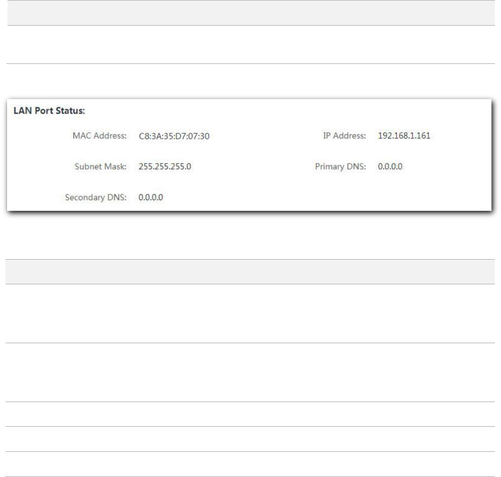
LAN Port Status
Parameter description
Parameter
Description
MAC Address
It specifies the physical address of the AP’s LAN port.
If you connect the AP to other devices using Ethernet cables, the AP uses this MAC
address to communicate with those devices.
IP Address
It specifies the IP address of the AP’s LAN port, which can be used to log in to the
web UI.
You can modify it on Internet Settings > LAN Setup page.
Subnet Mask
It specifies the subnet mask of the AP.
Primary DNS Server
It specifies the primary DNS server of the AP.
Secondary DNS Server
It specifies the secondary DNS server of the AP.
8
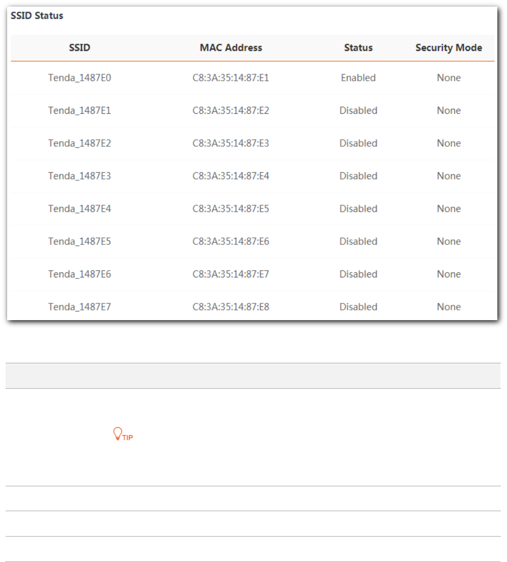
SSID status
Parameter description
Parameter
Description
SSID
Wireless network name of the AP. The AP supports up to 8 SSIDs on 2.4 GHz and 4 SSIDs
on 5 GHz.
The 1st SSID on the list indicates the primary SSID. By default, only the primary SSID on
each radio band is enabled.
MAC Address
It specifies the physical address of the corresponding wireless network.
Status
It specifies whether or not the corresponding WiFi network is enabled.
Security Mode
It specifies the security mode adopted by the corresponding WiFi network.
9
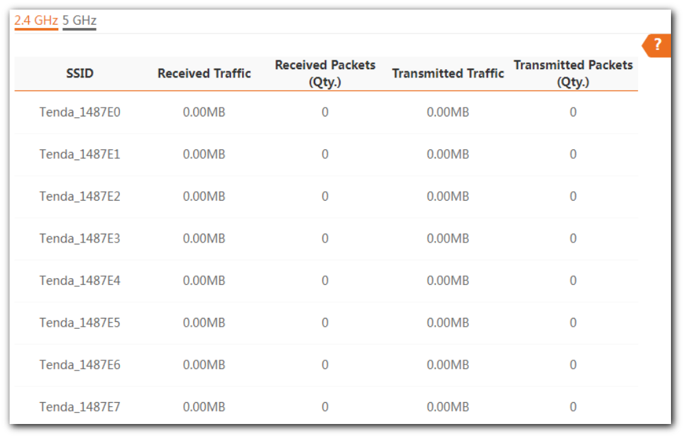
2.3 Traffic statistics
This page allows you to view statistical information about traffic based on SSIDs.
To access the page, choose Status > Traffic Statistics.

10
2.4 Client list
This page allows you to view wireless clients connected to each SSID of the AP and their basic
information, and to block unknown wireless clients. Here, “client” refers to the devices connected
to the AP’s wireless networks.
To access the page, choose Status > Client List.
Parameter description
Parameter
Description
SSID
Select the SSID from the drop-down list menu to view client information connected
to it.
MAC Address
It specifies the physical address of the client.
IP Address
It specifies the IP address of the client.
Client Type
It specifies the operating system of the client.
The AP identities the client type on two conditions:
The Identity Client Type function is enabled (To enable it, navigate to
Wireless > Advanced Settings).
The client connected to the AP has accessed an http:// website.
Otherwise, -- is displayed.
Connection Duration
It specifies the online time of the client.
Transmit Rate
It specifies the real time traffic the client has transmitted.
Receive Rate
It specifies the real time traffic the client has received.

11
Parameter
Description
Block
Click to block the client from accessing the AP’s wireless network.
To unblock a client, navigate to Wireless > Access Control.

12
3 Working mode
The AP supports AP mode (default mode) and Client+AP mode. This chapter introduces how to set
the working mode of the AP.
3.1 AP mode (default mode)
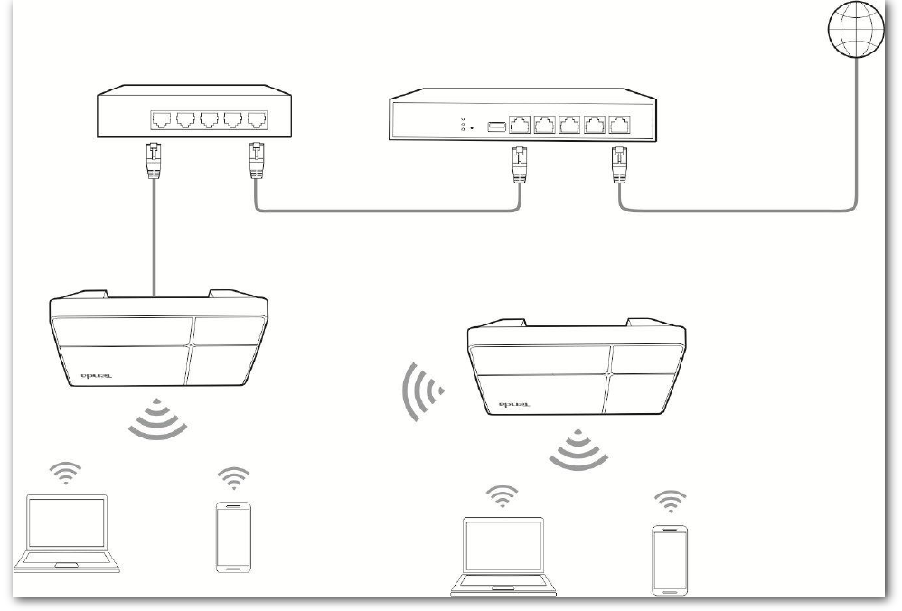
3.1.1 Typical network topology
In this mode, the AP connects to the internet in a wired manner, and converts wired network into
wireless network. See the following typical network topology.
Internet
Router
PoE Switch
AP (in AP mode)
13
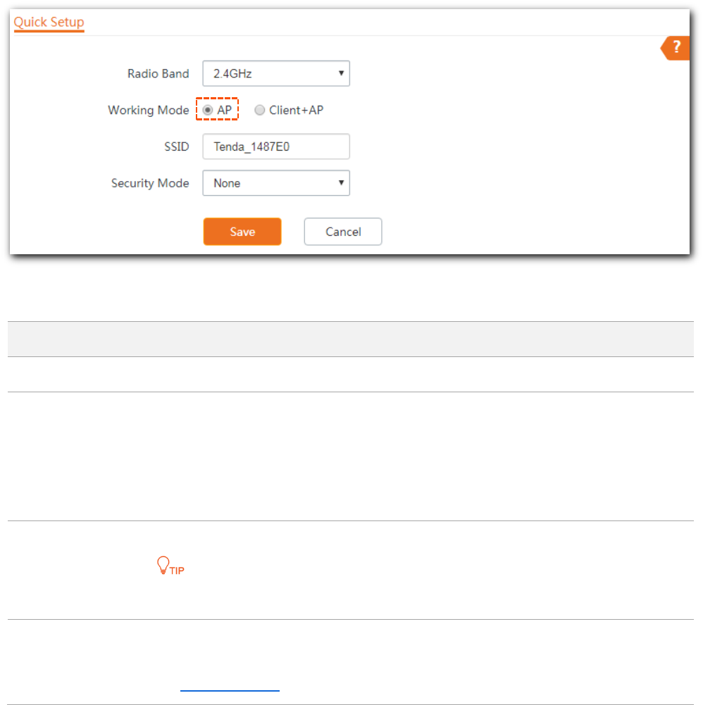
3.1.2 Getting familiar with AP mode configuration page
To access the configuration page, choose Quick Setup.
Parameter description
Parameter
Description
Radio Band
It is used to select the radio band for configurations.
Working Mode
It specifies the working modes supported by the device.
AP mode (default mode): This mode is used to deploy wireless networks by
connecting the AP to the internet in a wired manner.
Client+AP mode: This mode is used to extend the existing wireless network by
bridging the upstream wireless signals.
SSID
Primary Wireless network name of the AP.
The 1st SSID on each radio band indicates the primary SSID.
Security Mode
It specifies the security mode you set for your AP’s WiFi network, including None, WEP,
WPA-PSK, WPA2-PSK, Mixed WPA/WPA2-PSK, WPA and WPA2.
See Security Mode for details.
3.1.3 Configuring AP mode
Log in to the web UI of the AP, and choose Quick Setup to enter the configuration page first.

14
By default, the device works in AP mode.
The following introduces how to set the device into AP mode on 2.4 GHz band. Configuration on 5
GHz is identical.
The device supports up to 8 SSIDs on 2.4 GHz band and 4 SSIDs on 5 GHz band. The SSID-related
parameters on this page refer to the first (primary) SSID of the AP.
Before you start
Ensure that the upstream router has connected to the internet successfully.
Procedure
Step 1 Select 2.4 GHz from the Radio Band drop-down list menu.
Step 2 Set Working Mode to AP.
Step 3 Customize an SSID (wireless network name) in the SSID box, which is Tenda_WiFi in this
example. This SSID is also your primary SSID on 2.4 GHz band.
Step 4 Select the security mode from the Security Mode drop-down list menu, which is
WPA2-PSK in this example.
Step 5 Select the Encryption Algorithm, which is AES in this example.
Step 6 Set a WiFi password in the Key box.
Step 7 Click Save to apply your settings.
---- End
After configuration, you can connect wireless devices to the WiFi network of your AP using the SSID
and WiFi password you set.
15
3.2 Client+AP mode
3.2.1 Typical network topology
In this mode, the AP extends the existing wireless network by bridging the upstream wireless signals.
See the following typical network topology.
Internet
Router
PoE Switch
This AP
(in Client+AP mode)
Upstream AP
(in AP mode)

16
3.2.2 Getting familiar with Client+AP mode configuration page
To enter the configuration page, set Working Mode to Client+AP. See the following figure.
Parameter description
Parameter
Description
Radio Band
It is used to select the radio band for configurations.
Working Mode
It specifies the working modes supported by the device.
AP mode (default mode): This mode is used to deploy wireless networks by
connecting the AP to the internet in a wired manner.
Client+AP mode: This mode is used to extend the existing wireless network by
bridging the upstream wireless signals.
SSID
It specifies the wireless network name of the upstream wireless network you selected.
Security Mode
It specifies the security mode adopted by the upstream wireless network you selected.
See Security Mode for details.
Key
It specifies the WiFi password for the upstream wireless network you selected.
Refresh
Used to refresh the scan results.
Scan/Disable
Scan: Used to scan nearby available wireless networks. The scan results are
displayed on the lower page.
Disable: The button only appears after you clicked Scan. It is used to end the scan
operation and collapse the scan result.

17
3.2.3 Configuring Client+AP mode
Log in to the web UI of the AP, and choose Quick Setup to enter the configuration page first.
By default, the device works in AP mode.
The following introduces how to set the device into Client+AP mode on 2.4 GHz band.
Configuration on 5 GHz is identical.
This device does not support dual-band bridging in Client+AP mode. Enabling Client+AP mode on
2.4 GHz band clears Client+AP configuration (if any) on 5 GHz band. And vice versa.
Procedure
Step 1 Select 2.4 GHz from the Radio Band drop-down list menu.
Step 2 Set Working Mode to Client+AP.
Step 3 Click Scan. The nearby available radio signals appear on the lower page.
If the SSID for bridging is not displayed, check if your upstream wireless network is enabled. If not,
enable it. Then refresh the scan result.
Step 4 Select the WiFi network to bridge, which is Tenda_Router in this example.
The device detects and auto-fills SSID, Security Mode, Encryption, and Algorithm of the
upstream wireless network for you, except the Key, which requires you to enter manually.
Step 5 Click Save to apply your settings.

18
---- End
After the configuration, devices connected to the AP can access the upstream wireless network.
Scan result
Click to refresh
scan result.
Click to collapse scan result

19
4 Internet settings
4.1 LAN setup
4.1.1 Overview
This section introduces how to:
Modify the IP address obtaining method of the AP.
Modify device name.
Modify negotiation mode.
To access the configuration page, choose Internet Settings > LAN Setup.

20
Parameter description
Parameter
Description
MAC Address
It specifies the MAC address of the AP’s LAN port.
IP Address Type
It specifies IP address obtaining method of the AP.
Static IP (default): You are required to set related parameters manually.
DHCP (Dynamic IP Address): The AP automatically obtains related parameters from
a DHCP server on your LAN network.
IP Address
It specifies the LAN IP address (also the login IP address) of the AP. Default:
192.168.0.254.
Subnet Mask
It specifies the subnet mask of the AP. Default: 255.255.255.0.
Default Gateway
It specifies the gateway IP address of the AP.
Generally, enter the LAN IP address of the router which has internet accessibility into
this box.
Primary DNS
It specifies the IP address of the primary DNS server of the AP.
If DNS proxy function is supported on your router connected to the internet, you can
set the IP address of the primary DNS server to the LAN IP address of your router.
Otherwise, enter a correct DNS server IP address.
Secondary DNS
It specifies the IP address of the secondary DNS server of the AP. This parameter is
optional.
Device Name
It specifies the name of the AP.
For later convenient management, you are recommended to modify each AP’s name.
Optimize Ethernet
for
Faster Speed (Auto Negotiation): This option features a high data rate but short
transmission distance. Generally, we recommend you select this option.
Longer Distance (10 Mbps Half Duplex): This option features long transmission
distance but low data rate. Generally, the negotiated speed is 10 Mbps.
If the Ethernet cable connecting the Ethernet port of the AP to the peer device is longer
than 100 meters, the Longer Distance mode is recommended. In this case, ensure that
the peer device adopts auto negotiation option.

21
4.1.2 Configuring the AP to obtain IP address automatically (for
multiple APs)
To access the configuration page, choose Internet Settings > LAN Setup first.
Procedure
Step 1 Select DHCP (Dynamic IP Address) from the IP Address Type drop-down list menu.
The IP address-related parameters dimmed and cannot be configured.
Step 2 Click Save to apply your settings.
---- End
To view the new IP address assigned to the AP, go to the upstream DHCP client list.
*

22
4.1.3 Configuring the AP to use static IP address (for few APs)
To access the configuration page, choose Internet Settings > LAN Setup first.
Procedure
Step 1 Select Static IP from the IP Address Type drop-down list menu.
The IP address-related parameters become configurable.
Step 2 Customize required parameters.
Step 3 Click Save to apply your settings.
---- End
After the configuration, if the new IP address of the AP belongs to the same network segment as
the IP address of your management computer, you can log in to the web UI of the AP directly using
the new IP address. Otherwise, before logging in to the AP’s web UI using the new IP address, assign
your computer an IP address that belongs to the same network segment as the new IP address.
*
*
*
*
*

23
4.2 DHCP server
4.2.1 Overview
The AP supports the DHCP server function to assign IP addresses to devices connected to it. By
default, this function is disabled. After this function enabled, the following page appears.
If another DHCP server is available in your LAN, ensure that the IP address pool of the AP does not
overlap the IP address pool of that DHCP server. Otherwise, IP address conflicts may occur.
Parameter description
Parameter
Description
DHCP Server
It specifies whether or not to enable the DHCP server function of the AP.
Start IP Address
It specifies the start IP address of the DHCP server’s IP address pool. The default value
is 192.168.0.100.
End IP Address
It specifies the end IP address of the DHCP server’s IP address pool. The default value is
192.168.0.200.
The End IP address must be greater than the Start IP address.

24
Parameter
Description
Subnet Mask
It specifies the subnet mask assigned by the DHCP server to devices. The default value
is 255.255.255.0.
Gateway Address
It specifies the gateway IP address assigned by the DHCP server to devices. Generally, it
is the LAN IP address of the router connected to the internet. The default value is
192.168.0.1.
Only through a gateway can a LAN device access a server or host which is not in the
local network segment. You are recommended to enter a gateway IP address which can
access the internet. Otherwise, the device in the LAN network cannot access the
internet.
Primary DNS
It specifies the DNS server address provided by your ISP. If you do not know it, please
consult your ISP.
To enable devices to access the internet, set this parameter to a correct DNS server IP
address or DNS proxy IP address.
Secondary DNS
It specifies the second DNS server address (if any) provided by your ISP. This parameter
is optional, which indicates you can leave it blank if your ISP does not provide this
parameter.
Lease Time
It specifies the validity period of an IP address assigned by the DHCP server to a device.
By default, it is 1 day.
When half of the lease time has elapsed, the device sends a DHCP request to the DHCP
server to renew the lease time. If the request succeeds, the lease time is extended
based on the request. Otherwise, the device sends a request again when 7/8 of the
lease time has elapsed. If the request succeeds, the lease time is extended based on
the request. Otherwise, the device must request a new IP address from the DHCP
server after the lease time expires.
You are recommended to retain the default value.
4.2.2 Configuring DHCP server of the AP
To access the configuration page, choose Internet Settings > DHCP Server.
Procedure
Step 1 Enable DHCP Server function.
Step 2 Customize required parameters.

25
The End IP Address must be greater than the Start IP Address.
The Start IP Address, End IP Address, and Gateway Address must belong to the same network
segment as that of the LAN IP of the device.
Step 3 Click Save to apply your settings.
---- End
4.2.3 Viewing DHCP clients
To view DHCP clients and their connection information, choose Internet Settings > DHCP Server,
and click the DHCP Clients tab. See the following figure.
DHCP client list

27
Parameter description
Parameter
Description
SSID
Select one SSID from the drop-down list menu.
The AP allows you to enable 8 SSIDs on 2.4 GHz band, and 4 SSIDs on 5 GHz band.
Enable
Used to enable or disable the wireless network you selected.
Broadcast SSID
Enable: Nearby wireless clients can detect the SSID.
Disable: Nearby wireless clients cannot detect the SSID, and you need to enter
the SSID manually on the wireless client to access the wireless network.
Isolate Client
This parameter implements a function similar to the VLAN function for wired networks.
It isolates the wireless devices connected to the same WiFi network, so that the
wireless devices can access only the wired network connected to the AP. You can apply
this function to hotspot setup in public spaces, such as hotels and airports to improve
network security.
WMF
The number of wireless devices keeps increasing currently, but wired and wireless
bandwidth resources are limited. Therefore, the multicast technology, which enables
single-point data transmission and multi-point data reception, has been widely used in
networks in order to reduce bandwidth requirements and prevent network congestion.
Nevertheless, if a large number of devices are connected to a wireless interface of a
WiFi network and multicast data is intended for only one of the devices, the data is still
sent to all the devices, which increases unnecessary wireless resource usage and may
lead to wireless channel congestion. In addition, multicast stream forwarding over an
802.11 network is not secure, either.
The WMF function of the AP converts multicast traffic into unicast traffic and forwards
the traffic to the multicast traffic destination in the WiFi network, helping save wireless
resources, ensuring reliable transmission, and reducing delays.
Suppress Broadcast
Probe Response
If enabled, this device does not respond to the requests without an SSID, saving
wireless resources.
Max. Number of
Clients
This parameter specifies the maximum number of devices that can connect to the WiFi
network corresponding to an SSID. If the number is reached, the WiFi network rejects
new connection requests from devices. This limit helps balance load among SSIDs.
The AP supports 128 clients at most. That is to say, clients connected to all the enabled
wireless networks of the AP cannot exceed 128. If you enable multiple SSIDs, plan your
maximum number of clients to each SSID first.
Chinese SSID
Encoding
It specifies the character encoding format.
Available options include GB2312 and UTF-8.
A proper encoding format lets the SSID containing Chinese characters be displayed

28
Parameter
Description
normally across devices.
Security Mode
It specifies the security modes supported by the AP, including:
None: This wireless network is open. The security level is the lowest.
WEP: Wired Equivalent Privacy. The security level is very low.
WPA-PSK, WPA2-PSK, and Mixed WPA/WPA2-PSK: Applicable to most scenarios.
WPA and WPA2: This mode provides highest security level. It use 802.1 x RADUIS
to encrypt and is applicable to enterprises.
See Security Mode for details.
Security Mode
A WiFi network uses radio open to the public as its data transmission medium. If the WiFi network
is not protected by necessary measures, any device can connect to the network to access
unprotected data over the network or the resources of the network. To ensure communication
security, transmission links of WiFi network must be encrypted.
The AP supports various security modes for network encryption, including None, WEP, WPA-PSK,
WPA2-PSK, Mixed WPA/WPA2-PSK, and WPA/WPA2.
None
It indicates that any wireless device can connect to the WiFi network. This option is not
recommended because it leads to network insecurity.
WEP
It uses a static key to encrypt all exchanged data, and ensures that a WLAN has the same level of
security as a wired LAN. However, data encrypted based on WEP can be easily cracked. In addition,
WEP supports a maximum WiFi network throughput of only 54 Mbps. Therefore, this security mode
is not recommended.
Select WEP from the Security Mode drop-down list menu, the following parameters appear. See the
following figure.
30
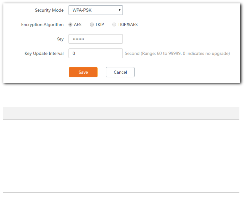
Select WPA-PSK (or WPA2-PSK, or Mixed WPA/WPA2-PSK) from the Security Mode drop-down list
menu, the following parameters appear. See the following figure.
Parameter description
Parameter
Description
Encryption Algorithm
The AP supports the following three encryption algorithms:
AES: Advanced Encryption Standard. This is newer Wi-Fi encryption solution used
by the new-and-secure WPA2 standard. It is more secure than TKIP.
TKIP: Temporal Key Integrity Protocol. This is an older encryption protocol
introduced with WPA. This option is recommended only when you have older
devices that can’t connect to a WPA2-PSK (AES) network.
AES&TKIP: It indicates that both AES and TKIP are supported.
Key
It indicates the key used for wireless clients to connect to the access point.
Key Update Interval
It indicates the interval at which a WPA key is updated. A shorter interval leads to
higher security.
WPA and WPA2
To address the key management weakness of WPA-PSK and WPA2-PSK, the WiFi Alliance puts
forward WPA and WPA2, which use 802.1x to authenticate devices and generate data encryption–
oriented root keys. WPA and WPA2 use the root keys to replace the pre-shared keys that set
manually, but adopt the same encryption process as WPA-PSK and WPA2-PSK.
WPA and WPA2 uses 802.1x to authenticate devices and the login information of a device is
managed by the device. This effectively reduces the probability of information leakage. In addition,
each time a device connects to an AP that adopts the WPA or WPA2 security mode, the RADIUS
server generates a data encryption key and assigns it to the device, which makes it difficult for
attackers to obtain the key. These features of WPA and WPA2 security modes help increase network
security significantly, making WPA and WPA2 the preferred security modes of WiFi networks that
require high security.
Select WPA (or WAP2) from the Security Mode drop-down list menu, the following parameters
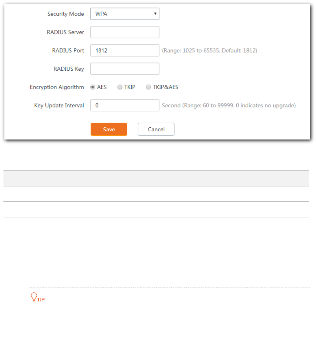
31
appear. See the following figure.
Parameter description
Parameter
Description
RADIUS Server
Enter the IP address of RADIUS server.
RADIUS Port
Enter the authentication port number of the RADIUS sever.
RADIUS Key
Enter the password used for RADIUS authentication.
5.1.2 Modifying SSID-related parameters
To enter the configuration page, choose Wireless > SSID first.
Procedure
The following takes configuration on 2.4 GHz band for example. Configuration on 5 GHz is identical.
The following introduces how to modify parameters on this page. Modify them based on your
actual requirements.
Step 1 Select the SSID from the SSID drop-down list menu.
Step 2 Set Status to Enable.
Step 3 (Optional) Enable Broadcast SSID, Isolate Client, Isolate SSID, WMF, and modify the
number of client that can connect to this specific SSID in the Max. Number of Clients box.

32
The AP supports 128 clients at most. That is to say, clients connected to all the enabled wireless
networks of the AP cannot exceed 128. If you enable multiple SSIDs, plan your maximum number
of clients to each SSID first.
The AP allows you to enable 8 SSIDs on 2.4 GHz band, and 4 SSIDs on 5 GHz.
Step 4 (Optional) Customize SSID and security-related parameters as required.
SSID: Modify the default one if necessary.
Chinese SSID Encoding: A proper encoding format lets the SSID containing Chinese
characters be displayed normally across devices.
Security Mode: Choose a security mode and configure related parameters.
Step 5 Click Save to apply your settings.
---- End

33
5.1.3 Example of configuring a WiFi network encrypted by WPA
or WPA2
Network topology
Configuration description
Configuring a WiFi network encrypted by WPA or WPA2 involves operations across various devices.
This guide will walk you through the configuration step by step.
The following table summarizes the overall steps. Get yourself familiar with the whole process
before you start.
Step
Task
Description
1
Configure the AP.
Select the SSID you want to implement the RADIUS authentication, and
enable it. Modify the SSID as required. Then set the security mode to
WPA2 and enter the RADISU server-related parameters.
2
Create RADIUS client.
Create a RADIUS client first, and then create a remote access policy.
3
Configure wireless network
information on the wireless
client.
Add the wireless network enabled with WPA or WPA2 of the AP
manually, and configure its security settings.
Internet
Router
PoE switch
AP
IP: 192.168.0.254
SSID: hot_spot
RADIUS server
IP: 192.168.0.200

34
Procedure
Step 1 Configure the AP.
In this case, we assume that you have installed and configured a RADIUS server in your company, and
have obtained the following information:
RADIUS Server: IP address or domain name of the RADIUS server, which is 192.168.0.200 in this
example.
RADIUS Port: Port number used for authentication, which is 1812 in this example
RADIUS Password: Password used for authentication which is 12345678 in this example.
Select an SSID from the SSID drop-down list menu, and set the Status to Enable. 1.
Modify the SSID to hot_spot. 2.
Select WPA2 from the Security Mode drop-down list menu. The RADIUS-related 3.
parameters appear.
Enter your RADIUS Server, RADIUS Port, and RADIUS Password. Parameters on the 4.
following figure are only for examples.
Set Encryption Algorithm to AES. 5.
Click Save to apply your settings. 6.

37
(3) Enter 12345678 in the Shared secret and Confirm shared secret text boxes, and click
Finish.
Configure a remote access policy. 2.
(1) Right-click Remote Access Policies and choose New Remote Access Policy.
(2) In the New Remote Access Policy Wizard dialog box that appears, click Next.
Shared secret should be the same as that
specified by RADIUS Password on the AP.

38
(3) Enter a policy name and click Next.
(4) Select Ethernet and click Next.

39
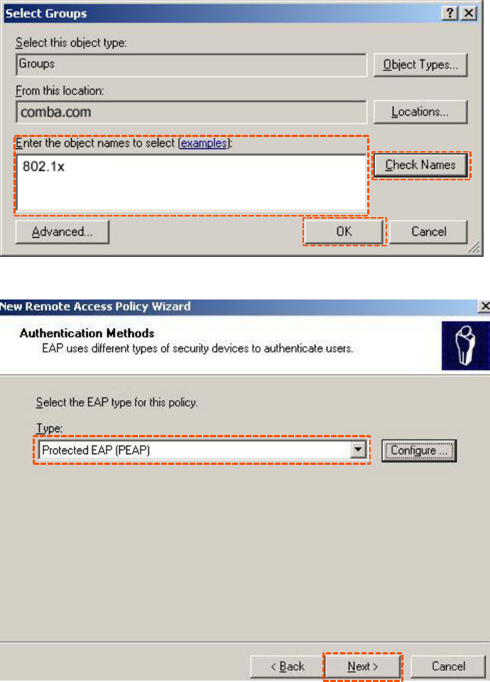
(5) Select Group and click Add.
(6) Enter 802.1x in the Enter the object names to select text box, click Check Names, and
click OK.
40
(7) Select Protected EAP (PEAP) and click Next.
(8) Click Finish. The remote access policy is created.
43
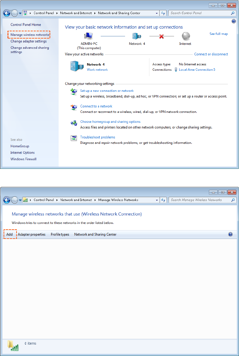
(2) Click Add.
(3) Click Manually create a network profile.
45
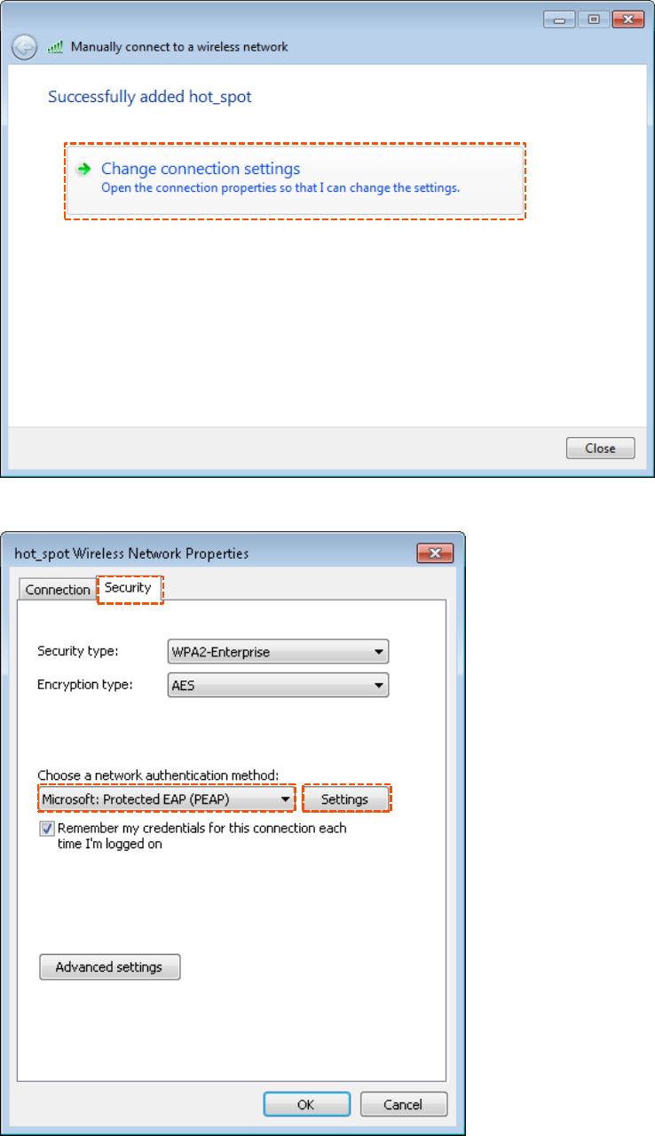
(6) Click the Security tab, select Microsoft: Protected EAP (PEAP), and click Settings.
Specyfikacje produktu
| Marka: | Tenda |
| Kategoria: | Wi-Fi |
| Model: | i24 |
Potrzebujesz pomocy?
Jeśli potrzebujesz pomocy z Tenda i24, zadaj pytanie poniżej, a inni użytkownicy Ci odpowiedzą
Instrukcje Wi-Fi Tenda

15 Stycznia 2025
4 Lipca 2024
4 Lipca 2024
4 Lipca 2024
4 Lipca 2024
4 Lipca 2024
4 Lipca 2024
4 Lipca 2024
4 Lipca 2024
4 Lipca 2024
Instrukcje Wi-Fi
- Wi-Fi Huawei
- Wi-Fi Panasonic
- Wi-Fi TRENDnet
- Wi-Fi D-Link
- Wi-Fi Siemens
- Wi-Fi Iiyama
- Wi-Fi HP
- Wi-Fi Strong
- Wi-Fi Akasa
- Wi-Fi Gembird
- Wi-Fi ZyXEL
- Wi-Fi Google
- Wi-Fi Netgear
- Wi-Fi AVM
- Wi-Fi Devolo
- Wi-Fi Draytek
- Wi-Fi Edimax
- Wi-Fi Maginon
- Wi-Fi Belkin
- Wi-Fi Quintezz
- Wi-Fi Ziggo
- Wi-Fi Proximus
- Wi-Fi Eminent
- Wi-Fi Sitecom
- Wi-Fi KlikaanKlikuit
- Wi-Fi Easypix
- Wi-Fi Envivo
- Wi-Fi ICIDU
- Wi-Fi Ubiquiti
- Wi-Fi Telenet
- Wi-Fi Grixx
- Wi-Fi Fantec
- Wi-Fi Verizon
- Wi-Fi T-Mobile
- Wi-Fi Premier
- Wi-Fi Sungevity
- Wi-Fi Mercku
- Wi-Fi Pentagram
- Wi-Fi Ubee
- Wi-Fi Lab 31
- Wi-Fi SolarNRG
- Wi-Fi Dartwood
- Wi-Fi Ryoko
- Wi-Fi On Networks
- Wi-Fi Telfort
- Wi-Fi DKT
Najnowsze instrukcje dla Wi-Fi

7 Lutego 2025
15 Stycznia 2025
13 Stycznia 2025
11 Stycznia 2025
28 Września 2024
27 Września 2024

27 Września 2024
27 Września 2024
27 Września 2024
27 Września 2024