Instrukcja obsługi Suunto X-Lander Military
Suunto
zegarek sportowy
X-Lander Military
Przeczytaj poniżej 📖 instrukcję obsługi w języku polskim dla Suunto X-Lander Military (100 stron) w kategorii zegarek sportowy. Ta instrukcja była pomocna dla 17 osób i została oceniona przez 2 użytkowników na średnio 4.5 gwiazdek
Strona 1/100

www.suunto.com
A LT I M A X | V E C T O R | X - L A N D E R
I N S T R U C T I O N M A N U A L
EN | FR | DE | ES | IT | NL | FI | SV


1. 2.
10.9.
8.7.6.5.
4.3.
12.11.


13. 14.
22.21.
20.19.18.17.
16.15.
24.23.

25. 26.
34.33.
32.31.30.29.
28.27.
36.35.


1
EN
Customer SERVICE Contacts
Suunto USA
Phone 1 (800) 543-9124
Suunto Canada
Phone 1 (800) 776-7770
Web Site www.suuntousa.com
Suunto Europe
Phone +33 3 90 20 74 30
Fax +33 3 90 20 74 40
Web Site www.suuntoeurope.com
Suunto Oy
Phone +358 9 875 870
Fax +358 9 8758 7301
Web Site www.suunto.com
Congratulations, your newly purchased Wristop Computer is designed to provide years of enjoyment in whatever
outdoor activities you engage.
Along with this product you will find a Warranty card, this Users Guide, and a full service support team to give
you the results you need anytime, anywhere, quickly and professionally.
We wish you many unforgettable moments with your new Wristop Computer!
INSTRUCTION MANUAL


2
TABLE OF CONTENTS
CHAPTER 1 INTRODUCTION .......................................................... 6
1.1 GENERAL INFORMATION ............................................................................................ 6
1.2 MAIN FUNCTIONS (MODES) ........................................................................................ 6
1.2.1 Backlight Features ........................................................................................... 7
1.2.2 Water Resistance ............................................................................................ 7
1.3 BUTTON FUNCTIONS ................................................................................................... 7
1.3.1 The [Mode] Button ........................................................................................... 7
1.3.2 The [+] Button .................................................................................................. 8
1.3.3 The [-] Button ................................................................................................... 8
1.3.4 The [Select] Button .......................................................................................... 8
1.4 LCD DISPLAY ................................................................................................................. 8
1.5 MEASUREMENTS AND UNITS .................................................................................. 10
1.5.1 Selecting the Units of Measurement ............................................................. 10
1.6 PRESSURE SENSOR CALIBRATION ........................................................................ 11
1.7 CARE AND MAINTENANCE ........................................................................................ 11
1.7.1 Battery Replacement ..................................................................................... 12
CHAPTER 2 TIME MODE ............................................................... 13
2.1 HOW TO SET THE TIME ............................................................................................. 13
2.2 DAILY ALARM SUB MODE .......................................................................................... 15
2.2.1 How to Set the Daily Alarms .......................................................................... 15
2.3 STOPWATCH SUB MODE .......................................................................................... 16
2.3.1 How to Use the Stopwatch ............................................................................ 16
2.4 COUNTDOWN TIMER SUB MODE ............................................................................ 18
2.4.1 How to Set the Countdown Timer ................................................................. 18


3
2.4.2 How to Start the Countdown Timer ............................................................... 18
2.5 DUAL TIME SUB MODE (ALTIMAX) ........................................................................... 19
2.5.1 Setting the Dual Time Function ..................................................................... 19
CHAPTER 3 ALTIMETER MODE .................................................... 20
3.1 SETTING THE ALTIMETER ......................................................................................... 21
3.2 ALTITUDE DIFFERENCE MEASUREMENT SUB MODE .......................................... 23
3.2.1 How to Start the Altitude Difference Measurement ....................................... 23
3.3 24-HOUR MEMORY SUB MODE ................................................................................ 24
3.4 LOGBOOK SUB MODE ............................................................................................... 24
3.4.1 How to Start and Stop a Logbook ................................................................. 26
3.4.2 Fast Cumulative Button ................................................................................. 26
3.5 LOGBOOK HISTORY SUB MODE .............................................................................. 27
3.5.1 Clearing the Logbook History ........................................................................ 28
CHAPTER 4 BAROMETER MODE .................................................. 28
4.1 PRESSURE DIFFERENCE MEASUREMENT SUB MODE ....................................... 29
4.1.1 How to Start the Pressure Difference Measurement .................................... 30
4.2 4-DAY MEMORY SUB MODE ...................................................................................... 30
4.3 SEA LEVEL PRESSURE SUB MODE......................................................................... 31
4.3.1 Setting the Sea Level Pressure .................................................................... 31
4.4 BAROMETRIC TREND INDICATOR ........................................................................... 32
CHAPTER 5 COMPASS MODE (VECTOR AND X-LANDER) ........... 32
5.1 BEARING TRACKING SUB MODE ............................................................................. 34
5.2 DECLINATION ADJUSTMENT SUB MODE ............................................................... 34
5.2.1 Setting the Local Declination ......................................................................... 35
5.3 CALIBRATING THE COMPASS .................................................................................. 35


4
CHAPTER 6 FREQUENTLY ASKED QUESTIONS .......................... 36
6.1 GENERAL ..................................................................................................................... 36
6.1.1 Is the Wristop Computer waterproof? ........................................................... 36
6.1.2 How long will the battery last? ....................................................................... 36
6.1.3 What do the segments on the circumference mean? ................................... 37
6.1.4 Why do the segments on the circumference go to the left
(counterclockwise)? ....................................................................................... 37
6.1.5 Why are there two symbols above the mode indicator bar and what do
they mean? .................................................................................................... 37
6.2 TIME .............................................................................................................................. 38
6.2.1 Why do the segments on the circumference increase and decrease when
I am in the Time mode? ................................................................................. 38
6.2.2 What is the longest time I can set in the timer? ............................................ 38
6.3 ALTIMETER .................................................................................................................. 38
6.3.1 How do you clear the logbook? ..................................................................... 38
6.3.2 How does the logbook self-erase? ................................................................ 38
6.3.3 How many logbooks can you record? ........................................................... 38
6.3.4 What is the duration readout? ....................................................................... 39
6.3.5 What is the maximum capacity of total vertical ascent or descent feet/
meters in the logbook history? ...................................................................... 39
6.3.6 If hiking from a level of 5,000 ft down hill to 3,000 ft and then back up to
8,000 feet, how is the Vector going to read this or average it out? .............. 39
6.3.7 Why does the vertical ascent/descent measurement show different
readings even though I am inside and staying in the same room? ............. 40
6.4 BAROMETER ............................................................................................................... 40
6.4.1 What is the little box on the top left of the display? ...................................... 40


5
6.4.2 Does the Wristop Computer show future trends in weather conditions? ..... 41
6.4.3 What does absolute pressure and relative pressure mean? ................... 41
6.4.4 What is temperature compensation? ............................................................ 41
6.5 COMPASS .................................................................................................................... 41
6.5.1 What is the purpose of the rotating outer bezel? .......................................... 41
6.5.2 Where do I find the correct declination for my area so I can set my
Wristop Computer? ........................................................................................ 42
6.6 EFFECT OF AIR TEMPERATURE ON ALTITUDE MEASUREMENT ........................ 42
7. SPARE PARTS AVAILABLE ........................................................ 44
8. ABBREVIATIONS ....................................................................... 45
9. COPYRIGHT AND TRADEMARK NOTICE .................................. 45
10. CE COMPLIANCE ..................................................................... 45
11. LIMITS OF LIABILITY AND ISO 9001 COMPLIANCE .............. 46


6
CHAPTER 1 INTRODUCTION
1.1 GENERAL INFORMATION
The Wristop Computer is a reliable high precision electronic instrument, intended for recreational use. The
outdoor enthusiast who enjoys venturing in sports like skiing, kayaking, mountain climbing, hiking and biking
can rely on the Wristop Computers accuracy.
The ergonomically designed Wristop Computer weighs only 2 ounces or 55 grams and is accompanied by a
LCD featuring a large number display intended to be clearly visible in almost any condition.
Note: The Wristop Computer should not be substituted for acquiring measurements that require professional or
industrial precision and should not be used to acquire measurements when skydiving, hang gliding, paragliding,
gyrocopter riding and flying small aircraft.
IMPORTANT NOTE: A PULLOUT PAGE LOCATED ON THE FRONT INSIDE COVER OF THIS MANUAL
GRAPHICALLY ILLUSTRATES AND IDENTIFIES THE PROPERTIES OF THE WRISTOP COMPUTER AND
LCD DISPLAY. THIS PAGE IS DESIGNED TO FACILITATE THE USERS UNDERSTANDING OF THE
FUNCTIONS AND PROCESSES TO SETUP THOSE FUNCTIONS.
1.2 MAIN FUNCTIONS (MODES)
Though the users guide applies to all the Wristop Computer models, functions and differences in operation of
the models are noted in the table below.
Functions Wristop Computer Models
Altimax Vector X-Lander
Time YES YES YES
Altimeter YES YES YES
Barometer YES YES YES
Compass - YES YES


7
In each of the functions, associated sub modes provide further enhancements to the usefulness of its owner. All
key features and sub modes are discussed in detail following this section.
Note: Wristop Computer models Vector and X-Lander provide the same features. The difference is the Vector
is housed in a sturdy plastic case and the X-Lander is brushed aluminum.
1.2.1 Backlight Features
The Wristop Computer has an electroluminescent backlight. This is initiated by pressing and holding the [Mode]
button for 2 seconds. The backlight will remain on for 5 seconds. Pressing the [Mode] button during this time
will restart the 5 second period, continuing the backlight feature.
1.2.2 Water Resistance
This product is water resistant. Water resistance is tested to 30m/100ft according to ISO 2281 standard (www.iso.ch).
Note: The Wristop computer is not a dive instrument.
1.3 BUTTON FUNCTIONS
Four buttons are used to operate the Wristop Computer: [Mode], [+] (ON/OFF), [-] (Fast Bearing), and [Select].
1.3.1 The [Mode] Button
Is located on the top right of the Wristop Computer.
In the main mode level, pressing the [Mode] button allows the user to select or move from one mode or
function to the next (TIME, ALTI, BARO, COMP).
In the sub mode level, pressing the [Mode] button returns the user to the main mode level.
In the setup process, pressing the [Mode] button accepts the changes or preferences. Pressing the button
again will return the user to the main mode level.
Pressing the button for 2 seconds activates the backlight feature.


10
1.5 MEASUREMENTS AND UNITS
The Wristop Computer supplies two units of measure: metric or imperial.
Metric Unit of Measure Imperial Unit of Measure
m ft
m/min ft/min
°C °F
mbar inHg
1.5.1 Selecting the Units of Measurement
To change the unit of measure displayed:
1. Check the mode indicator. If the mode arrow is not on TIME, PRESS the [Mode] button until the arrow is
directly below TIME on the Mode Indicator Bar.
2. PRESS the [Mode] and [Select] buttons simultaneously and hold in for 3 seconds. Field 1 will display SET
momentarily and then display UNI (Fig. 43).
Note: If the user does not press any button for 1 minute in the setup mode, the display will automatically exit
setup.
WARNING: If the user presses the [Select] button (and does not hold for 2 seconds) while in the UNI setting
mode, the user will be in the Pressure Sensor Calibration. Refer to the next section for details.
3. PRESS the [Select] button and hold in for 2 seconds. Located to the right in Field 2, m or ft will begin to
flash.
4. PRESS the [+] button to toggle between m and ft.
5. At the unit of measure desired, PRESS the [Select] button to move to the next unit. Located below the m or
ft in Field 2, mbar or inHg will begin to flash.
6. PRESS the [+] button to toggle between mbar and inHg.
7. At the unit of measure desired, PRESS the [Select] button to move to the next unit. Located at the top right
in Field 1 (just above the bubble), °C or °F will begin to flash.
8. PRESS the [+] button to toggle between °C and °F.


11
9. At the unit of measure desired, PRESS the [Select] button to move to the next unit. Located at the top
center in Field 1, m/min or ft/min will begin to flash.
10 PRESS the [+] button to toggle between m/min and ft/min.
11 At the unit of measure desired, PRESS the [Mode] button to accept the changes. PRESS the [Mode] button
again to return to the main time mode.
Selecting the units of measurement is complete.
1.6 PRESSURE SENSOR CALIBRATION
This is a FACTORY SETTING CALIBRATION. If you are in this mode we highly suggest that you exit this
setting by pressing the [Mode] button. Calibrating this setting will ADVERSELY IMPACT all altitude and barometric
settings of the Wristop Computer.
In this setting, the user will be viewing SNR (Sensor) in Field 1. Do not press the [+] or [-] button to adjust the
pressure. Simply exit this setting by pressing the [Select] button to return to the UNI setting mode or by
pressing the [Mode] button to return to the main mode.
If the Pressure Setting Calibration has been altered, in error, please contact our Product Support Department.
1.7 CARE AND MAINTENANCE
Perform only the detailed processes discussed in this manual. Do not perform any other service to the Wristop
Computer or attempt to open the case or remove the buttons or the bezel.
Protect your Wristop Computer from shocks, extreme heat and prolonged exposure to direct sunlight. If not in
use, your Wristop Computer should be stored in a clean, dry environment at room temperature.
The Wristop Computer can be wiped clean with a lightly moistened (warm water) cloth. Applying a mild soap to
the area can clean stubborn stains or marks.
Avoid exposing the Wristop Computer to strong chemicals like gasoline, cleaning solvents, acetone, alcohol,
adhesives, and paint, as they will damage the units seals, case and finish.
Never attempt to take the Wristop Computer apart or service it yourself. Make sure the area around the sensors
(backside of the instrument) is kept free of dirt and sand. Never insert any objects into the sensor openings of
the Wristop Computer.


12
1.7.1 Battery Replacement
The Wristop Computer operates on a three-volt lithium cell Type: CR 2430. The maximum life expectancy is
approximately 12-18 months.
A low battery-warning indicator is activated when 5-15 percent of the battery capacity is still available. When
this occurs we recommend replacement of the battery.
Extreme cold weather will activate the low battery-warning indicator. Though the indicator is activated, the
battery may not need to be replaced due to this condition. In temperatures above 10°C (50°F) and the low
battery warning indicator is activated, the battery will need to be replaced.
Note: Heavy use of the electroluminescent backlight, altimeter, and compass will significantly reduce the life of
the battery.
To replace the battery:
1. turn the Wristop Computer to view the backside;
2. insert a coin in the coin slot located on the battery compartment cover;
3. turn the coin counterclockwise to the open position marked on the back of the case;
4. remove the battery compartment cover;
5. remove the old cell from the battery compartment and ensure the o-ring and all surfaces are clean, dry and
not damaged. Do not stretch the o-ring;
6. place the new cell into the battery compartment (negative side down, positive side up);
7. ensure that the o-ring is in its place to keep the Wristop Computer waterproof. Place the battery compartment
cover back onto the backside of the Wristop Computer;
8. insert a coin back into the coin slot; and
9. turn the coin clockwise to the close position marked on the back of the case.
Note: Battery replacement should be performed with extreme care so as to ensure the Wristop Computer
continues to remain waterproof.It is the operators responsibility to take due care to ensure that the Wristop
Computer remains waterproof.

14
4. PRESS the [+] button to scroll the minutes upward or
PRESS the [-] button to scroll the minutes downward.
5. At the minutes desired, PRESS the [Select] button to move to the next setting. Located in the center of
Field 2, the hour will begin to flash.
6. PRESS the [+] button to scroll the hour upward or
PRESS the [-] button to scroll the hour downward.
7. At the hour desired, PRESS the [Select] button to move to the next setting. Located in Field 1, the 24 or 12
hour clock setting will begin to flash.
8. PRESS either the [+] or the [-] button to toggle between the 24hr and 12hr.
Note: If the 12 hour clock is chosen either AM/PM will appear below the hour in Field 2.
9. At the clock setting desired, PRESS the [Select] button to move to the next setting. Located in the center of
Field 2, the year will begin to flash (Fig. 12).
10. PRESS the [+] button to scroll the year upward or
PRESS the [-] button to scroll the year downward.
11. At the year desired, PRESS the [Select] button to move to the next setting. Located in the center of Field 3,
the month represented by a number will begin to flash.
12. PRESS the [+] button to scroll the month upward or
PRESS the [-] button to scroll the month downward.
13. At the month desired, PRESS the [Select] button to move to the next setting. Located to the right of Field 3,
the date will begin to flash.
14. PRESS the [+] button to scroll the date upward or
PRESS the [-] button to scroll the date downward.
Note: Once the user has determined the year, month and day, the Wristop Computer will supply the day of the
week in Field 1. The American month/day -view can not be changed to a day/month -view.
15. At the desired date, PRESS the [Mode] button to accept the changes and return to the main mode.


15
Note: If the user does not press any button for 1 minute in the setup mode, the display will automatically exit
setup.
Setting the time is now complete.
2.2 DAILY ALARM SUB MODE
The Wristop Computer allows the user to select and enter settings for up to three alarms.
In the TIME mode, PRESS the [Select] button once to enter this sub mode.
In the Daily Alarm sub mode (Fig. 39) :
Field 1 displays ON or OFF (the activation status of a particular alarm),
Field 2 displays the time of a particular alarm, and
Field 3 displays the alarm (1, 2, or 3) the user is viewing.
Press the [+] or [-] button to select alarms 1,2, or 3. Then, change the settings in the manner described in the
following section.
2.2.1 How to Set the Daily Alarms
1. PRESS the [+] or the [-] button to select the desired alarm to be set (1,2, or 3).
2. PRESS the [Select] button and hold in for 2 seconds. Located in Field 1, the ON or OFF will begin to
flash.
3. PRESS either the [+] or the [-] button to toggle between ON and OFF.
4. At the setting desired, PRESS the [Select] button to move to the next setting. Located in the center of Field
2, the hour will begin to flash.
5. PRESS the [+] button to scroll the hour upward or
PRESS the [-] button to scroll the hour downward.
6. At the hour desired, PRESS the [Select] button to move to the next setting. Located on the right of Field 2,
the minutes will begin to flash.
7. PRESS the [+] button to scroll the minutes upward or
PRESS the [-] button to scroll the minutes downward.


16
8. At the minutes desired, PRESS the [Mode] button to accept the changes and exit the setup program. A small
bell will appear at the bottom left side in Field 2 to signify an alarm has been activated.
The Alarm setup is complete. To activate up to three alarms, please repeat steps 1-8 for the selected alarm
(1,2, or 3).
Note: The Alarm volume can not be changed.
2.3 STOPWATCH SUB MODE
The Wristop Computer stopwatch sub mode can provide split time measurement and two finish times up to
23 hours 59 minutes and 59 seconds.
In the TIME mode, PRESS the [Select] button twice to enter this sub mode.
In the Stopwatch sub mode (Fig. 40):
Field 1 displays the seconds and tenths of a second,
Field 2 displays the current time, and
Field 3 displays hours and minutes and to the far right stopwatch.
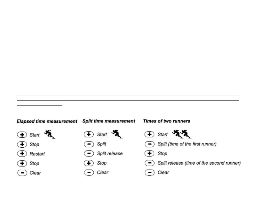
2.3.1 How to Use the Stopwatch
There are three timing modes the user can employ:
an elapsed time measurement;
a split time measurement; and
a two finish time measurement.
In the elapsed time mode:
1. PRESS the [+] button to start, stop, and restart the stopwatch in the stopwatch sub mode.
2. PRESS the [-] button to reset the stopwatch to zero once the stopwatch has stopped.
In the split time mode:
1. PRESS the [+] button to start the stopwatch in the stopwatch sub mode.

17
2. PRESS the [-] button once to stop the stopwatch and to display a split time.
3. PRESS the [-] button a second time to release the split time display and resume the stopwatch.
4. PRESS the [+] button to stop the stopwatch.
5. PRESS the [-] button to reset the stopwatch to zero once the stopwatch has stopped.
In the two finish time mode:
1. PRESS the [+] button to start the stopwatch in the stopwatch sub mode.
2. PRESS the [-] button once to stop the stopwatch to display the finish time of the first person.
3. PRESS the [+] button to stop the stopwatch.
4. PRESS the [-] button a second time to release and display the finish time of the second person.
5. PRESS the [-] button to clear and to reset the stopwatch.
Note: When the stopwatch function is activated, the stopwatch will continue and remain in the background if the
user is in other modes or sub modes. The user can identify the stopwatch is still activated by the flashing text
stopwatch in Field 3.


18
2.4 COUNTDOWN TIMER SUB MODE
In the TIME mode, PRESS the [Select] button three times to enter this sub mode.
In the countdown timer sub mode (Fig. 41):
Field 1 displays the seconds,
Field 2 displays the current time, and
Field 3 displays the hours and minutes and to the bottom far right the text timer.
2.4.1 How to Set the Countdown Timer
1. PRESS the [Select] button and hold in for 2 seconds. Located in Field 1, the seconds will begin to flash.
2. PRESS the [+] button to scroll the seconds upward or
PRESS the [-] button to scroll the seconds downward.
3. At the seconds desired, PRESS the [Select] button to move to the next setting. Located on right of Field 3,
the minutes will begin to flash.
4. PRESS the [+] button to scroll the minutes upward or
PRESS the [-] button to scroll the minutes downward.
5. At the minutes desired, PRESS the [Select] button to move to the next setting. Located in the center of Field
3, the hour will begin to flash.
6. PRESS the [+] button to scroll the hour upward or
PRESS the [-] button to scroll the hour downward.
7. At the hour desired, PRESS the [Mode] button to accept the changes and exit the setup program.
8. The countdown timer setup is complete.
2.4.2 How to Start the Countdown Timer
To start the countdown timer:
1. PRESS the [+] button to start, stop, and restart the timer in the countdown timer sub mode.
2. PRESS the [-] button to reset the timer to zero once the timer has stopped.


19
Note: When the countdown timer is activated, the countdown timer will continue and remain in the background
if the user is in other modes or sub modes. The user can identify the countdown timer still activated by the
flashing text timer in Field 3.
2.5 DUAL TIME SUB MODE (ALTIMAX)
Note: This feature applies to the Altimax Wristop Computer
In the TIME mode, PRESS the [Select] button four times to enter this sub mode.
In the dual time mode (Fig. 42):
Field 1 displays dUA indicating dual time,
Field 2 displays the current time, and
Field 3 displays the dual time (e.g. your home time).
The user can display the seconds while in this sub mode by pressing the [+] button, in Field 3 the seconds will
appear for 10 seconds. Afterwards the display returns back to showing the dual time.
2.5.1 Setting the Dual Time
In the dual time sub mode:
1. PRESS the [Select] button and hold in for 2 seconds. Located in Field 3, the hours will begin to flash.
2. PRESS the [+] button to scroll the hours upward or
PRESS the [-] button to scroll the hours downward.
3. At the hour desired, PRESS the [Select] button to move to the next setting. Located in Field 3 to the right of
the hour value, the minutes will begin to flash.
4. PRESS the [+] button to scroll the minutes upward or
PRESS the [-] button to scroll the minutes downward.
5. At the minutes desired, PRESS the [Mode] button to accept the changes and exit the setup program.
6. The dual time setup is complete.


20
The dual time stays the same, even though the time in the main time mode is adjusted. For example, if you set
the dual time to show your home time, your home time will always be displayed in this sub mode even though
you travel to a different time zone and adjust the time in the main time mode.
Note: The dual time function is completely independent and does not affect the alarms or the memory functions.
These are dependent of the current local time.
CHAPTER 3 ALTIMETER MODE
The Altimeter mode provides the user with:
an adjustable unit of measure either meter or feet: meter range -500 to 9,000; ft range -1,600 to 29,500;
a resolution of 5m or 10ft;
a display up-date on the rate of vertical movement in intervals of 1 second for 3 minutes, then every 10
seconds or less;
an automatic 24-hour memory in one hour intervals showing altitude and vertical ascent/descent rate; and
a logbook, recording approximately 3800 sets of data (one set = altitude, vertical ascent/descent rate and
time).
To view and use the Altimeter mode:
Check the Mode Indicator Bar. If the mode arrow is not on ALTI, PRESS the [Mode] button until the arrow is
directly below ALTI on the bar.
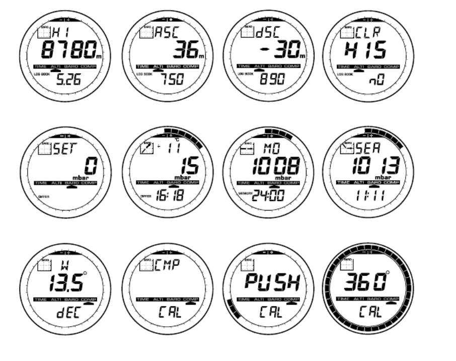
In the ALTIMETER mode (Fig. 1):
Field 1 displays the vertical ascent or descent rate;
Field 2 displays the current altitude in increments of 5 meters or 10 feet (depending on the unit of measure
selected); and
Field 3 displays the current time.
The Outer Circumference graphically displays the altitude in hundreds of meters or feet over a full thousand
where one complete circle is equivalent to 1000.
I TMPOR ANT NOTE: IN ORDER TO SET THE ALTITUDE IN THE ALTIMETER MODE, THE ALTITUDE MUST
BE KNOWN. THAT INFORMATION CAN BE FOUND BY UTILIZING A TOPOGRAPHICAL MAP, IDENTIFYING


21
THE CURRENT LOCATION WITH THE ASSOCIATED ALTITUDE MARKED. THE USER CAN PROCEED
AND FOLLOW THE INSTRUCTIONS, SETTING THE ALTIMETER, PROVIDED IN THE SECTION BELOW.
DETAILS REGARDING THE EFFECT OF AIR TEMPERATURE ON ALTITUDE MEASUREMENT ARE SHOWN
ON PAGE 41 OF THIS MANUAL.
IF THE ALTITUDE IS NOT KNOWN, THE USER CAN SET THE SEA LEVEL PRESSURE IN THE BAROMETRIC
MODE (REFER TO PAGE 31, SETTING THE SEA LEVEL PRESSURE).
SETTING THE SEA LEVEL PRESSURE WILL ADJUST THE AL ALTIMETER TO THE CURRENT TITUDE
WITHIN SOME TEN METERS OR FEW HUNDRED FEET.
INFORMATION ON THE CURRENT SEA LEVEL PRESSURE CAN BE OBTAINED THROUGH NEWSPAPERS,
LOCAL NEWS AND RADIO WEATHER REPORTS, THE LOCAL AIRPORT FACILITY OR THROUGH THE
INTERNET UNDER LOCAL WEATHER.
3.1 SETTING THE ALTIMETER
In setting the Altimeter, there are three processes that can be performed:
the Reference Altitude (known altitude at the current location),
the Altitude Alarm (signifies the user when a certain altitude, programmed, is reached), and
the Logbook Recording Interval (allows the user to view the altitude and rate of vertical movement within a
chosen interval of time).
To begin:
1. PRESS the [Select] button and hold in for 2 seconds. Located in Field 1 is the text RE (indicating reference
altitude), located in Field 2, the current altitude will begin to flash (Fig. 2).
2. PRESS the [+] button to scroll the altitude upward or
PRESS the [-] button to scroll the altitude downwards.
3. At the desired reference altitude, either PRESS the [Mode] button to accept the changes and return to the
main mode or PRESS the [Select] button to move to the next setting. Located in Field 1, the ON or OFF
will begin to flash (Fig. 3).
4. PRESS either the [+] or the [-] button to toggle between the ON and OFF for the Altitude Alarm.


22
5. At the desired setting, PRESS the [Select] button to move to the next setting. Located in the center of Field
2, the alarm altitude will begin to flash.
6. PRESS the [+] button to scroll the altitude upward or
PRESS the [-] button to scroll the altitude downwards.
7. At the desired altitude, either PRESS the [Mode] button to accept the changes and return to the main mode
or PRESS the [Select] button to move to the next setting. Located in Field 1, the text INT and located in Field
2 the time interval will begin to flash (Fig. 4).
8. PRESS either the [+] or the [-] button to scroll through the intervals. There are four time intervals 20 seconds,
1 minute, 10 minute or 60 minute.
Recommended interval to use:
Activity Interval
Skiing 20 sec or 1 minute
Biking 20 sec or 1 minute
Hiking 10 Minute
Mountaineering 10 minute or 60 minute
Note: In selecting the interval, the user chooses a) the time period for recording the altitude, the vertical ascent/
descent rate as well as the current time to be stored into the logbook and b) the timeout or maximum recording
time of a logbook. The shorter the interval the more accurate the information due to the fact the sampling rate
is faster. Timeouts are discussed on page 25.
9. At the desired interval, PRESS the [Mode] button to accept the changes and exit the setup program.
Once the user completes the process in setting the reference altitude of the current location to the known
altitude, the Wristop Computer will also correct the sea level pressure, and therefore, it will not be necessary for
this function to be set.
Note: If the user does not press any button for 1 minute in the setup mode, the display will automatically exit
setup.
Note: A 10-minute recording interval means that the Wristop Computer records data every 10 minutes.


23
3.2 ALTITUDE DIFFERENCE MEASUREMENT SUB MODE
In the Altimeter mode, PRESS the [Select] button once to enter this sub mode.
In the Altitude Difference measurement sub mode (Fig. 13):
Field 1 displays the vertical ascent or descent rate;
Field 2 displays the current altitude in increments of 5 meters or 10 feet depending on the unit of measure
selected; and
Field 3 displays the running time; to the left of the time is the text differ.
The Outer Circumference graphically displays the altitude in hundreds of meters or feet over a full thousand
where one complete circle is equivalent to 1000.
The running time is displayed up to 39 hours and 59 minutes; after which three dashes (-:--) appear on the
display in Field 3. If the user allows the difference measurement sub mode to remain on visual display continuously
for 12 hours, the Wristop Computer will automatically return to the main time mode.
This mode does continue in the background and allows the user to move to other modes and at the convenience
of the user can return to this sub mode to display the current status.
Note: The difference measurement mode is a relative measurement. Any change in the reference altitude
during the altitude difference measurement will effect the measured altitude. We recommend that the reference
altitude always be checked and set again prior to beginning a new measurement.
3.2.1 How to Start the Altitude Difference Measurement
1. PRESS the [Select] button and hold in for 2 seconds. Located in Field 1 is the text SET; located in Field 2,
zero will begin to flash (Fig. 14).
2. PRESS the [Mode] button to accept the flashing zero and start the difference measurement.
If the user does not desire to begin the difference measurement, PRESS either the [+] or the [-] button to toggle
to the current altitude then PRESS the [Mode] button to exit the setup program.
Note: If the user does not press any button for 1 minute in the setup mode, the display will return to the main
mode without zeroing the altimeter.

24
3.3 24-HOUR MEMORY SUB MODE
In the Altimeter mode, PRESS the [Select] button twice to enter this sub mode.
In the 24-hour memory sub mode (Fig. 15):
Field 1 displays the vertical ascent or descent rate;
Field 2 displays the current altitude in increments of 5 meters or 10 feet depending on the unit of measure
selected; and
Field 3 displays the particular hour and to the left the text memory.
The Outer Circumference displays graphically the altitude in hundreds of meters or feet over a full thousand
where one complete circle is equivalent to 1000.
To view the information compiled in the 24-hr memory:
1. PRESS the [-] button to scroll back down in increments of one hour and view the vertical ascent/descent
rate and the altitude for that particular hour.
2. PRESS the [+] button to scroll back up.
Note: Replacing the battery will not erase this information.
3.4 LOGBOOK SUB MODE
In the Altimeter mode, PRESS the [Select] button three times to enter this sub mode. The logbook mode
features five displays. The displays automatically rotate showing the first display for 7 seconds then proceeds
showing displays 2 through 5 at 4 second intervals.
In the first display (Fig. 16):
Field 1 displays the year;
Field 2 displays the text LO with the current logbook number flashing; and
Field 3 displays the month and day of the particular logbook number. To the left of the month/day, is the text
Log Book.
The user can PRESS the [-] to scroll down to view previous logs captured and then PRESS [+] to scroll up to the
current logbook.


25
The second display shows the ascent information for the particular logbook that is being viewed (Fig. 17).
Field 1 displays the average ascent rate during the event;
Field 2 displays the total vertical ascent ; and
Field 3 displays the text ASC along with the text Log Book to the left.
The third display shows the descent information for the particular logbook that is being viewed (Fig. 18).
Field 1 displays the average descent rate during the event;
Field 2 displays the total vertical descent; and
Field 3 displays the text dSC along with the text Log Book to the left.
The fourth display shows the number of laps (runs; either ascents or descents) completed for the particular
logbook that is being viewed (Fig. 19).
Field 2 displays the total number of ascents or descents ; and
Field 3 displays the text LAP along with the text Log Book to the left.
Note: A Lap is a vertical movement either ascent or descent equaling 150 ft (50 meters) or above.
The fifth display shows the time duration of recording information in the particular logbook that is being viewed
(Fig. 20).
Field 2 displays the total time of the log ; and
Field 3 displays the text dUr along with the text Log Book to the left.
Note: If the logbook is recording, based on the interval chosen the logbook will record up to that particular time
period. Once the time period has been reached the Wristop Computer, will alert the user that the logbook
recording has expired (known as a timeout). For setting the logbook interval refer to Setting the Altimeter on
Page 21.
The timeouts are as follows: Logbook intervals Maximum recording time
20 second 10 hours
1 minute 12 hours
10 minute 7 days
60 minute 10 days


26
3.4.1 How to Start and Stop a Logbook
For the Vector and X-Lander models:
In the Altimeter main mode or the difference measurement sub mode, PRESS the [+] button. A beep will be
heard and the flashing text Log Book will appear in Field 3 to indicate the start of the recording.
Note: For the Vector and X-Lander models,while in the recording phase of the current logbook, the user will be
unable to view this data. The user can view this data only after the recording session has stopped, but previously
recorded logbooks can be viewed at any time.
The recording can be stopped by pressing the [+] a second time. A beep will be heard and the Log Book text
will be removed from Field 3 indicating recording has stopped.
Note: In order to prevent accidental starts/stops of a logbook, the Vector or X-Lander models should be in
another function other than the altimeter mode. If the logbook is activated the logbook will continue to recorded
even if the Vector or X-Lander is in another mode.
For the Altimax model:
Logbook recording starts by pressing the [+] button twice within 2 seconds. Logbook recording stops by pressing
the [+] button twice as well within 2 seconds.
Note: For the Altimax, Vector and X-Lander models logbooks are self-erasing and cannot be cleared by the user.
Note: If you desire greater precision, start new logbooks more often or lower the recording interval.
3.4.2 Fast Cumulative Button
This function is furnished in the Altimax model. This allows the user to check the cumulative vertical ascent/
descent in feet or meters, as well as number of runs of the current logbook while recording.
Accessing this information is performed by pressing the [-] button in any of the main modes. When activated,
three displays will automatically rotate in intervals of four seconds.
The first display shows the accumulative vertical ascent since the beginning of the current logbook.
The second display shows the accumulative vertical descent since the beginning of the current logbook.
And finally, the third display shows the number of runs accomplished during the current logbook.


27
After the third display is shown, the Altimax automatically returns to the main mode in which the user was
viewing.
Note: During this process, pressing the [-] button allows the user to move on to the next of the three displays.
3.5 LOGBOOK HISTORY SUB MODE
The Logbook history shows a summation of all logs recorded.
In the Altimeter mode, PRESS the [Select] button four times to enter this sub mode. The logbook history mode
features four displays.
In the first display (Fig. 24):
Field 1 displays the year when the logbook history has been last cleared;
Field 2 displays the text HIS; and
Field 3 displays the month and day when the logbook history has been last cleared. To the left of the month/
day, displayed is the text Log Book.
PRESS [+] to scroll through the different displays.
In the second display (Fig. 25):
Field 1 displays the text HI;
Field 2 displays the highest altitude recorded since the last date cleared; and
Field 3 displays the date when it was reached with the text Log Book to the left.
In the third display (Fig. 26):
Field 1 displays the text ASC;
Field 2 and 3 show up to an 8 digit accumulative vertical ascent since the last reset. Field 2 is activated
when the value of the vertical ascent is beyond the 3 digit value displayed in Field 3.
In the fourth display (Fig. 27):
Field 1 displays the text dSC;
Field 2 and 3 show up to an 8 digit accumulative vertical descent since the last reset. Field 2 is activated
when the value of the vertical ascent is beyond the 3 digit value displayed in Field 3.


28
3.5.1 Clearing the Logbook History
To clear the history of the logbook (Fig. 28):
1. In any of the logbook history displays, PRESS the [Select] button and hold in for 2 seconds. Located in Field
1 is the text CLR; in Field 2 the text HIS; and in Field 3, nO will begin to flash.
2. PRESS the [+] button to toggle between YES and NO.
3. PRESS the [Mode] button to accept the option YES.
The logbook history is erased and a new starting date is set to begin new cumulative measurements.
Note: If the user does not press any button for 1 minute in the setup mode, the display will automatically exit
setup.
We recommend that the logbook history be cleared prior to beginning logbook recording(s).
CHAPTER 4 BAROMETER MODE
The Barometer mode provides the user with:
an adjustable unit of measure mbar or inHg; mbar range 300 to 1 100 mbar, inHg range 8.90 to 32.40;
a resolution of 1 mbar or 0.05 inHg;
a one hour interval measuring to estimate barometric trend;
an automatic 4-day memory of atmospheric pressure for the last 6 hours in 1-hour intervals, thereafter, in 6-
hour intervals;
temperature compensation (temperature does not effect the pressure within the specified temperature range)
a temperature range -20O to 60OC or -5O to 140OF; and
a temperature resolution of 1O C or F.
Note: Body heat will effect temperature when the Wristop Computer is worn on the wrist. To achieve an accurate
reading remove the Wristop Computer from the wrist and allow at least 15 minutes before reading the temperature.
If youve been in the barometric mode for more than 15 minutes with no rate of vertical movement, you should
allow 1 hour for the Wristop Computer to adjust the temperature. To acquire a quicker up-date of the temperature,
press the [Mode] button 4 times to re-enter the mode.


29
To view and use the Barometer mode:
Check the Mode Indicator Bar. If the mode arrow is not on BARO, PRESS the [Mode] button until the arrow is
directly below BARO on the bar.
In the Barometer mode (Fig. 5):
Field 1 displays the current temperature.
Field 2 displays the current absolute atmospheric pressure.
Field 3 displays the current time.
The Outer Circumference graphically displays the atmospheric pressure over 100 millibars or 1 inHg where
one complete circle is equivalent to 100 mbar/1 inHg, depending on the unit of measure chosen.
Note: The absolute pressure is the actual pressure in any location at any given time. Where as, sea level
pressure is the corresponding pressure at sea level.
4.1 PRESSURE DIFFERENCE MEASUREMENT SUB MODE
The pressure difference is not referring to the sea level pressure, but to the current barometric pressure measured
by the watch.
In the Barometer mode, PRESS the [Select] button once to enter this sub mode.
In the Pressure Difference Measurement mode (Fig. 30):
Field 1 displays the change in temperature.
Field 2 displays the change in atmospheric pressure.
Field 3 displays the current time; to the left of the time is the text differ.
The Outer Circumference graphically displays the change in pressure where one full circle equals 100
mbars or 1 inHg.
This mode does continue in the background and allows the user to move to other modes and at the users
convenience can return to this sub mode to show the current reading.


30
4.1.1 How to Start the Pressure Difference Measurement
1. PRESS the [Select] button and hold in for 2 seconds. Located in Field 1 is the text SET; located in Field 2,
zero will begin to flash (Fig. 29).
2. PRESS the [Mode] button to accept the flashing zero and start the difference measurement.
If the user does not desire to begin the difference measurement, PRESS either the [+] or the [-] button to toggle
to the current barometric pressure reading, then PRESS the [Mode] button to exit the setup program.
Note: If the user does not press any button for 1 minute in the setup mode, the display will automatically exit
setup.
4.2 4-DAY MEMORY SUB MODE
In the Barometer mode, PRESS the [Select] button twice to enter this sub mode. This function allows the user
to follow changes in pressure that will assist forecasting changes in weather condition (i.e. storms).
In the 4-day memory sub mode (Fig. 31):
Field 1 displays the day of the week the user is in;
Field 2 displays the atmospheric pressure; and
Field 3 displays the time and to the left the text memory.
The Outer Circumference graphically displays the atmospheric pressure where one full circle equals
100 mbars or 1 inHg.
To view the information compiled in the 4-day memory:
PRESS the [-] button to scroll back down in increments of one hour for the first six hours, after that increments
are 6 hours.
PRESS the [+] button to scroll back up.
Note: Replacing the battery will not erase this information.


31
4.3 SEA LEVEL PRESSURE SUB MODE
Sea level pressure is pressure relative to sea level where as the pressure read in the main barometric display
is absolute pressure in the current location.
In the Barometer mode, PRESS the [Select] button three times to enter this sub mode.
In the sea level pressure sub mode (Fig. 32):
Field 1 displays the text SEA;
Field 2 displays the current sea level pressure; and
Field 3 displays the current time.
4.3.1 Setting the Sea Level Pressure
Setting the sea level pressure can be used in setting the altitude measurement on the Wristop Computer if the
altitude is not known.
To set the sea level pressure:
1. PRESS the [Select] button and hold in for 2 seconds. Located in Field 2, the current sea level pressure will
begin to flash.
2. PRESS the [+] button to scroll the pressure upward or
PRESS the [-] button to scroll the pressure downward.
3. At the desired pressure, PRESS the [Mode] button to accept the changes and return to the main mode.
Once the user completes this process, the altitude measurement on the Wristop Computer is correct within a
range of some ten meters or few hundred feet.
Note: Information on the current sea level pressure can be obtained through newspapers, local news and radio
weather reports, the local airport facility or through the Internet under local weather.
If the user does not press any button for 1 minute in the setup mode, the display will automatically exit setup.


33
bearing degrees;
a North-South arrow;
a bearing track mode showing desired direction and actual bearing;
a bubble level for accuracy reading +3 degrees (except in the X-Lander);
a rotating bezel;
a resolution of 1° for the bearing, +5° for North-South direction; and
a declination correction feature.
To view and use the Compass Mode:
Check the Mode Indicator Bar. If the mode arrow is not on COMP, PRESS the [Mode] button until the arrow is
directly below COMP on the bar.
In the COMPASS mode (Fig. 6):
Field 1 displays the cardinal or half-cardinal point.
Field 2 displays the bearing in degrees.
Field 3 displays the current time.
The Outer Circumference graphically displays the North-South arrow where one-lit segment shows North
and three-lit segments show South.
The Wristop Computer provides a bubble level for the user to achieve a precise reading within +3 degrees. The
user should acquire a bearing by removing the Wristop Computer from the wrist. The user centers the liquid
bubble to ensure the Wristop Computer position is level and takes a reading.
The compass display is active for 45 seconds at a time. After this, the compass enters sleep mode and an -
--° indicator appears in the field 2. Reactivate the compass by pressing the [-] button.
Note: Compass readings should be performed away from objects possessing sources of magnetism. Avoid
buildings, large metal objects, power lines, loudspeakers, electric motors etc.
Always take bearings in the open air, not inside tents, caves, or other shelters.


34
5.1 BEARING TRACKING SUB MODE
The user can select to change from the cardinal point mode to the bearing track function and utilize the bearing
lock function in this mode for tracking purposes (Fig. 7).
In the compass main mode:
1. PRESS the [Select] button and hold in for 2 seconds. Located in Field 1, OFF will begin to flash (Fig. 8).
2. PRESS either the [+] or the [-] button to change the setting between OFF and ON.
3. At the selection desired, PRESS the [Select] button to move to the next setting. Located in Field 2, the actual
bearing in degrees will begin to flash (Fig. 9).
4. Turn the Wristop Computer to the desired direction. Lock the bearing displayed by pressing the [-] button.
5. Adjust the locked bearing, if necessary by pressing the [Select] button and then adjusting the value with the
[+] and [-] buttons.
6. At the desired bearing to track, PRESS the [Mode] button to accept the changes and exit the setup program.
Note: If the user does not press any button for 1 minute in the setup mode, the display will automatically exit
setup.
Note: Locking in the Bearing Trading sub mode blocks the compass reading.
5.2 DECLINATION ADJUSTMENT SUB MODE
The Wristop Computer allows the user to compensate the difference between true north and magnetic north.
This process is accomplished by adjusting the declination, resulting in the user obtaining correct compass
readings.
In the Compass mode, PRESS the [Select] button once to enter this sub mode.
In the Declination Adjustment sub mode (Fig. 33):
Field 1 displays the declination direction OFF where
OFF = no declination; W = West; E = East.
Field 2 displays declination in degrees.
Field 3 displays the text dEC.


35
5.2.1 Setting the Local Declination
1. PRESS the [Select] button and hold in for 2 seconds. Located in Field 1, OFF will begin to flash.
2. PRESS either the [+] or the [-] button to change the declination direction in Field 1.
3. At the direction desired, PRESS the [Select] button to move to the next setting. Located in Field 2, the
degrees will begin to flash.
4. PRESS the [+] button to scroll the degrees upward or
PRESS the [-] button to scroll the degrees downward.
5. At the degrees desired, PRESS the [Mode] button to accept the changes and exit the setup program.
Note: If the user does not press any button for 1 minute in the setup mode, the display will automatically exit
setup.
Local Declination is now set.
5.3 CALIBRATING THE COMPASS
A compass calibration should be done when the Wristop Computer is subject to close proximity of magnetic
sources, extreme cold weather, every time the battery is replaced or suspected that other environmental conditions
have effected the compass readings.
Note: We also recommend calibrating the compass before using the compass the first time and every time
leaving for a hike where the compass will be used.
To begin the calibration:
1. PRESS the [Select] button twice when in the main compass mode. Field 1 displays the text CMP. Field 3
displays the text CAL (Fig. 34).
2. PRESS the [Select] button and hold in for 2 seconds. Located in Field 2, the text PUSH will begin to flash
(Fig. 35).
3. PRESS the [-] button to start calibration.
4. In Field 2, 360° appears and the Outer Circumference displays all segments lit (Fig. 36). When this occurs,
hold the Wristop Computer level and start to slowly turn the device around a full circle in a level position. The

36
direction of turning does not matter. The lit segments will be turned off as the turning proceeds. When the
first full circle is completed, the instrument will inform the user within one minute of whether the calibration
was successful displaying the text dOnE in Field 2 (Fig. 37) or if the process needs to be repeated displaying
PUSH and - in Field 2.
Note: The user may need to perform the rotating of the compass more than twice around for the calibration to
be completed.
Note: During calibration, it is not necessary that all peripheral segments light up or turn off.
Note: If the text FAIL appears in Field 2 (Fig. 38), the battery should be removed and put back in before trying
to proceed with the calibration process. The removal of the battery will reset the unit.
5. Once the calibration is successful, PRESS the [Mode] button to accept the process and exit the calibration
mode.
Note: It is important to hold the Wristop Computer level during the calibration process to ensure accuracy.
The compass calibration is complete.
CHAPTER 6 FREQUENTLY ASKED QUESTIONS
6.1 GENERAL
6.1.1 Is the Wristop Computer water resistant?
Yes, it is water resistant to a depth of 30 meters (100 ft). Rain and other normal exposure to water will not effect
its operation. You can swim wearing your Wristop Computer. However, the Wristop Computer is NOT a diving
device.
6.1.2 How long will the battery last?
All users employ the product in different ways. Battery life depends mainly on how much the backlight, the
compass and the logbook are used. The low-battery warning symbol appears on the display when 5 to 15
percent of battery capacity remains. This should give the user plenty of time to safely change the battery.

37
6.1.3 What do the segments on the circumference mean?
In the Altimeter mode, one full circle equals 1,000 meters or 1,000 feet, therefore the segments on the
circumference graphically show the user the altitude over a full thousand. When using the difference measurement
function of the altimeter, the segments indicate the vertical difference in the elevation over a full thousand either
to the right if youre ascending or to the left if youre descending.
In the Barometer mode, one full circle equals 100 mbar or 1 inHg, and the segments indicate the pressure over
a full hundred mbar or over a full inHg. When using the difference measurement function of the barometer, the
segments indicate the change in atmospheric pressure either to the right if the pressure has risen or to the left
if the pressure has dropped.
In the main Compass mode, the segments indicate the North, i.e. the one segment indicates North and the
three segments point South. If you have set the compass to track a certain bearing, the segments on the
circumference indicate the difference between the direction in which you want to go and your actual bearing.
6.1.4 Why do the segments on the circumference go to the left
(counterclockwise)?
Normally, they always go to the right (clockwise) from the 12-noon position.
You are in the difference measurement mode and your unit is showing a decreasing value. In normal mode, the
segment display increases clockwise, but if you are in a mode that shows you differences (such as vertical
ascent/descent), all decreasing values go counterclockwise from the center position, and all increasing values
go clockwise. So, it is minus to the left (counterclockwise), and plus to the right (clockwise).
6.1.5 Why are there two symbols above the Mode Indicator Bar
and what do they mean?
The left-hand symbol indicates that the altitude alarm is activated and the right-hand symbol indicates that one,
two, or three daily alarms are activated.


40
Third, if thinking about the difference measurement function and how this is affected by the example situation,
the Wristop Computer will show you the absolute difference between 5,000 ft and 8,000 ft (beginning and end).
The fact that youve been down to 3,000 ft in-between does not have an impact on the absolute vertical altitude
difference between starting point and finish.
Last, the automatic 24-hour memory will show this information in the following way: Say you are starting out at
5,000 ft at noon, and then it takes you 2 hours to descend to 3,000 ft, and another five hours to reach 8,000 ft.
The scrollable displays in the 24-hour memory shows you the altitude 5,000 ft at 12:00 am, e.g.4,000 ft at 1
p.m., 3,000 ft at 2 p.m., e.g. 4,000 ft 3 p.m., 5,000 ft at 4 p.m., 6,000 ft at 5 p.m., 7,000 ft at 6 p.m. and then 8,000
ft at 7 p.m.
These are the different cases in which the example situation will affect the readings of the Wristop Computer.
Most important to remember is to ALWAYS set the known reference altitude into the Wristop Computer. This is
the only way to get accurate altitude readings.
6.3.7 Why does the vertical ascent/descent measurement show
different readings even though I am inside and staying in the
same room?
The resolution of the vertical ascent/descent rate is 1 m/1 ft whereas the resolution of the altitude display is 5 m/
10 ft, which means that the ascent/descent rate can show movement even though you remain at the same
altitude. This is caused by changes in pressure or even vertical movement within the 5 m/10 ft resolution range.
Indoors, even small, unnoticeable air currents cause changes in air pressure. For example, if you have a
window open at the other end of your house, the air current may affect a room at the other end of the building
so little that you do not notice it, but the sensors of the Wristop Computer do. Because the Wristop Computer
measures ascent and descent based on changes in air pressure, it interprets these changes as vertical movement.
6.4 BAROMETER
6.4.1 What is the little box on the top left of the display?
It is the barometric trend indicator that shows the general direction of weather changes. The display is based on
barometer measurements for the last 6 hours.


Specyfikacje produktu
| Marka: | Suunto |
| Kategoria: | zegarek sportowy |
| Model: | X-Lander Military |
Potrzebujesz pomocy?
Jeśli potrzebujesz pomocy z Suunto X-Lander Military, zadaj pytanie poniżej, a inni użytkownicy Ci odpowiedzą
Instrukcje zegarek sportowy Suunto

22 Września 2024
10 Września 2024
10 Września 2024
5 Września 2024
5 Września 2024
3 Września 2024
3 Września 2024
2 Września 2024
1 Września 2024
31 Sierpnia 2024
Instrukcje zegarek sportowy
- zegarek sportowy Samsung
- zegarek sportowy Motorola
- zegarek sportowy Beurer
- zegarek sportowy Sanitas
- zegarek sportowy Xiaomi
- zegarek sportowy Huawei
- zegarek sportowy Livoo
- zegarek sportowy SilverCrest
- zegarek sportowy Epson
- zegarek sportowy Mio
- zegarek sportowy Withings
- zegarek sportowy Asus
- zegarek sportowy Nedis
- zegarek sportowy Medion
- zegarek sportowy Polar
- zegarek sportowy Garmin
- zegarek sportowy Casio
- zegarek sportowy Evolveo
- zegarek sportowy Sigma
- zegarek sportowy Prixton
- zegarek sportowy Honor
- zegarek sportowy Amazfit
- zegarek sportowy Krontaler
- zegarek sportowy TFA
- zegarek sportowy Scosche
- zegarek sportowy Medisana
- zegarek sportowy Fitbit
- zegarek sportowy Crane
- zegarek sportowy Oppo
- zegarek sportowy Cateye
- zegarek sportowy Crivit
- zegarek sportowy Omron
- zegarek sportowy Pyle
- zegarek sportowy Apple
- zegarek sportowy Bryton
- zegarek sportowy SPC
- zegarek sportowy Ronstan
- zegarek sportowy Adidas
- zegarek sportowy Oregon Scientific
- zegarek sportowy Lezyne
- zegarek sportowy Hama
- zegarek sportowy TomTom
- zegarek sportowy Denver
- zegarek sportowy Bushnell
- zegarek sportowy Wahoo Fitness
- zegarek sportowy Trevi
- zegarek sportowy Timex
- zegarek sportowy ADE
- zegarek sportowy Lamax
- zegarek sportowy Clas Ohlson
- zegarek sportowy Goodis
- zegarek sportowy ACME
- zegarek sportowy Asics
- zegarek sportowy Proscan
- zegarek sportowy Diesel
- zegarek sportowy Silva
- zegarek sportowy Cresta
- zegarek sportowy Brigmton
- zegarek sportowy Sunstech
- zegarek sportowy Kubo
- zegarek sportowy Soehnle
- zegarek sportowy Ventus
- zegarek sportowy NGM
- zegarek sportowy Runtastic
- zegarek sportowy Naxa
- zegarek sportowy Umidigi
- zegarek sportowy Ematic
- zegarek sportowy Fossil
- zegarek sportowy Echowell
- zegarek sportowy Sportline
- zegarek sportowy Celly
- zegarek sportowy Mondaine
- zegarek sportowy Slazenger
- zegarek sportowy Ticwatch
- zegarek sportowy Ciclo
- zegarek sportowy GolfBuddy
- zegarek sportowy CicloSport
- zegarek sportowy Billow
- zegarek sportowy Geonaute
- zegarek sportowy Guardo
- zegarek sportowy Misfit
- zegarek sportowy Coros
- zegarek sportowy Kikos
- zegarek sportowy Swami
- zegarek sportowy Cubot
- zegarek sportowy Fen
- zegarek sportowy IZZO Golf
- zegarek sportowy Bitween
- zegarek sportowy Prologue
- zegarek sportowy Soleus
- zegarek sportowy Cmee
- zegarek sportowy Cressi
- zegarek sportowy Abyx
Najnowsze instrukcje dla zegarek sportowy
10 Marca 2025
10 Marca 2025
10 Marca 2025
10 Marca 2025
20 Lutego 2025
20 Lutego 2025
4 Stycznia 2025
4 Stycznia 2025
26 Grudnia 2024
26 Grudnia 2024