Instrukcja obsługi Supermicro MBD-X8SIL-O
Supermicro
płyta główna
MBD-X8SIL-O
Przeczytaj poniżej 📖 instrukcję obsługi w języku polskim dla Supermicro MBD-X8SIL-O (101 stron) w kategorii płyta główna. Ta instrukcja była pomocna dla 8 osób i została oceniona przez 2 użytkowników na średnio 4.5 gwiazdek
Strona 1/101

USER’S MANUAL
Revision 1.0c
X8SIL-F
X8SIL
X8SIL-V

Manual Revision 1.0c
Release Date: April 20, 2010
Unless you request and receive written permission from Super Micro Computer, Inc., you may not
copy any part of this document.
Information in this document is subject to change without notice. Other products and companies
referred to herein are trademarks or registered trademarks of their respective companies or mark
holders.
Copyright © 2010 by Super Micro Computer, Inc.
All rights reserved.
Printed in the United States of America
The information in this User’s Manual has been carefully reviewed and is believed to be accurate.
The vendor assumes no responsibility for any inaccuracies that may be contained in this document,
makes no commitment to update or to keep current the information in this manual, or to notify any
person or organization of the updates. Please Note: For the most up-to-date version of this
manual, please see our web site at www.supermicro.com.
Super Micro Computer, Inc. ("Supermicro") reserves the right to make changes to the product
described in this manual at any time and without notice. This product, including software, if any,
and documentation may not, in whole or in part, be copied, photocopied, reproduced, translated or
reduced to any medium or machine without prior written consent.
IN NO EVENT WILL SUPER MICRO COMPUTER, INC. BE LIABLE FOR DIRECT, INDIRECT,
SPECIAL, INCIDENTAL, SPECULATIVE OR CONSEQUENTIAL DAMAGES ARISING FROM THE
USE OR INABILITY TO USE THIS PRODUCT OR DOCUMENTATION, EVEN IF ADVISED OF
THE POSSIBILITY OF SUCH DAMAGES. IN PARTICULAR, SUPER MICRO COMPUTER, INC.
SHALL NOT HAVE LIABILITY FOR ANY HARDWARE, SOFTWARE, OR DATA STORED OR USED
WITH THE PRODUCT, INCLUDING THE COSTS OF REPAIRING, REPLACING, INTEGRATING,
INSTALLING OR RECOVERING SUCH HARDWARE, SOFTWARE, OR DATA.
Any disputes arising between manufacturer and customer shall be governed by the laws of Santa
Clara County in the State of California, USA. The State of California, County of Santa Clara shall
be the exclusive venue for the resolution of any such disputes. Supermicro's total liability for all
claims will not exceed the price paid for the hardware product.
FCC Statement: This equipment has been tested and found to comply with the limits for a Class
A digital device pursuant to Part 15 of the FCC Rules. These limits are designed to provide
reasonable protection against harmful interference when the equipment is operated in a commercial
environment. This equipment generates, uses, and can radiate radio frequency energy and, if not
installed and used in accordance with the manufacturer’s instruction manual, may cause harmful
interference with radio communications. Operation of this equipment in a residential area is likely
to cause harmful interference, in which case you will be required to correct the interference at your
own expense.
California Best Management Practices Regulations for Perchlorate Materials: This Perchlorate
warning applies only to products containing CR (Manganese Dioxide) Lithium coin cells. “Perchlorate
Material-special handling may apply. See www.dtsc.ca.gov/hazardouswaste/perchlorate”.
WARNING: Handling of lead solder materials used in this
product may expose you to lead, a chemical known to
the State of California to cause birth defects and other
reproductive harm.
Preface
This manu al is writ t en f o r sy ste m i nte g rato rs, P C tech nic ians and
knowledgeable PC users. It provides information for the installation and use of the
X8SIL/X8SIL-F/X8SIL-V motherboard.
About This Motherboard
The X8SIL/X8SIL-F/X8SIL-V supports the Intel® Xeon® 3400 series pro-
cessors in an LGA 1156 socket. With the Intel 3400/3420 chipset built-in, the X8SIL/
X8SIL-F/X8SIL-V offers substantial enhancements in price/system performance
ratio in a cost-effective, small form-factor package. Please refer to our web site
(http://www.supermicro.com/products/) for updates on supported processors. This
product is intended to be installed and serviced by professional technicians.
Manual Organization
Chapter 1 describes the features, specications and performance of the mother-
board and provides detailed information about the chipset.
Chapter 2 provides hardware installation instructions. Read this chapter when in-
stalling the processor, memory modules and other hardware components into the
system. If you encounter any problems, see , which describes troubleChapter 3 -
shooting procedures for video, memory and system setup stored in the CMOS.
Chapter 4 includes an introduction to the BIOS and provides detailed information
on running the CMOS Setup utility.
Appendix A provides BIOS Error Beep Codes.
Appendix B lists Other Software Program Installation Instructions.
Appendix C contains the BIOS Recovery Instructions.
Preface
iii
Conventions Used in the Manual:
Special attention should be given to the following symbols for proper installation and
to prevent damage done to the components or injury to yourself:
Danger/Caution: Instructions to be strictly followed to prevent catastrophic
system failure or to avoid bodily injury
Warning: Important information given to ensure proper system installation
or to prevent damage to the components
Note: Additional Information given to differentiate various models or pro-
vides information for correct system setup.

vi
X8SIL/X8SIL-F/X8SIL-V User’s Manual
Table of Contents
Preface
About This Motherboard ................................................................................................ 3
Manual Organization ..................................................................................................... 3
Conventions Used in the Manual: ................................................................................. 3
Contacting Supermicro .................................................................................................. 4
Chapter 1 Introduction
1-1 Overview ......................................................................................................... 1-1
Checklist .......................................................................................................... 1-1
Motherboard Features ..................................................................................... 1-6
1-2 Chipset Overview ......................................................................................... 1-10
Intel 3400/3420 Chipset Features ................................................................. 1-10
1-3 PC Health Monitoring .....................................................................................1-11
Recovery from AC Power Loss ......................................................................1-11
Onboard Voltage Monitoring .........................................................................1-11
Fan Status Monitor with Software ..................................................................1-11
CPU Overheat LED and Control ...................................................................1-11
1-4 Power Conguration Settings.........................................................................1-11
Slow Blinking LED for Suspend-State Indicator ........................................... 1-12
BIOS Support for USB Keyboard.................................................................. 1-12
Main Switch Override Mechanism ................................................................ 1-12
1-5 Power Supply ................................................................................................ 1-12
1-6 Super I/O ....................................................................................................... 1-13
1-7 iSCSI Support ............................................................................................... 1-13
1-8 Overview of the Nuvoton BMC Controller ..................................................... 1-14
Chapter 2 Installation
2-1 Static-Sensitive Devices .................................................................................. 2-1
Precautions ..................................................................................................... 2-1
Unpacking ....................................................................................................... 2-1
2-2 Processor and Heatsink Installation................................................................ 2-2
Installing the LGA1156 Processor ................................................................... 2-2
Installing a Passive CPU Heatsink ................................................................. 2-5
Removing the Heatsink ................................................................................... 2-6
Installing an Active Fan CPU Heatsink ........................................................... 2-7
2-3 Installing DDR3 Memory ............................................................................... 2-10
DIMM Installation .......................................................................................... 2-10
Memory Support ............................................................................................ 2-10

X8SIL/X8SIL-F/X8SIL-V User’s Manual
viii
TPM Support Enable ............................................................................... 2-33
Energy Saving Enable .............................................................................. 2-33
USB Wake-Up ......................................................................................... 2-34
BMC Jumper ............................................................................................ 2-34
2-8 Onboard Indicators ........................................................................................ 2-35
LAN 1/LAN 2 LEDs .................................................................................. 2-35
IPMI Dedicated LAN LEDs ..................................................................... 2-35
Onboard Power LED 6 ............................................................................................................ 2-3
IPMI Heartbeat LED ................................................................................. 2-36
2-9 SATA and Floppy Drive Connections ............................................................ 2-37
SATA Connections .................................................................................... 2-37
Floppy Connector ..................................................................................... 2-38
Chapter 3 Troubleshooting
3-1 Troubleshooting Procedures ........................................................................... 3-1
Before Power On ............................................................................................ 3-1
No Power ........................................................................................................ 3-1
No Video ......................................................................................................... 3-1
Memory Errors ............................................................................................... 3-2
Losing the System’s Setup Conguration ....................................................... 3-2
3-2 Technical Support Procedures ........................................................................ 3-2
3-3 Frequently Asked Questions ........................................................................... 3-3
3-4 Battery Removal and Installation .................................................................... 3-6
Battery Removal .............................................................................................. 3-6
Battery Installation ........................................................................................... 3-6
3-5 Returning Merchandise for Service................................................................. 3-7
Chapter 4 BIOS
4-1 Introduction ...................................................................................................... 4-1
Starting BIOS Setup Utility .............................................................................. 4-1
How To Change the Conguration Data ......................................................... 4-1
How to Start the Setup Utility ......................................................................... 4-2
4-2 Main Setup ...................................................................................................... 4-2
4-3 Advanced Setup Congurations...................................................................... 4-4
4-4 Security Settings ........................................................................................... 4-22
4-5 3 Boot ................................................................................................Settings 4-2
4-6 Exit Options ................................................................................................... 4-24
Chapter 1: Introduction
1-3
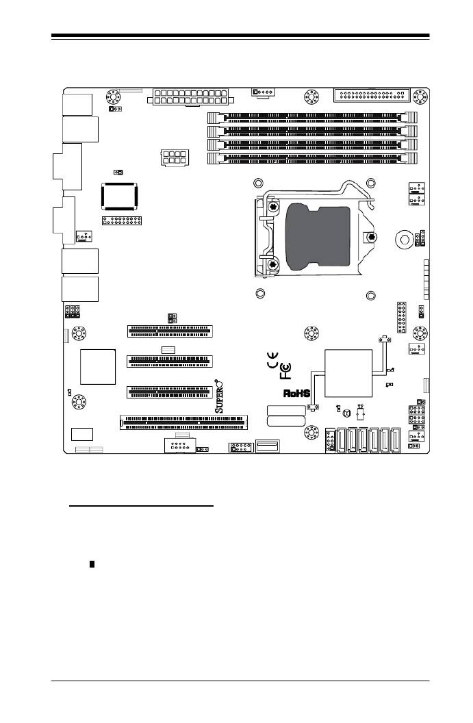
Motherboard Layout
Important Notes to the User
See Chapter 2 for detailed information on jumpers, I/O ports and JF1 front •
panel connections.
" " indicates the location of "Pin 1". •
Jumpers not indicated are for testing only. •
When LE2 (Onboard Power LED Indicator) is on, system power is on. Unplug •
the power cable before installing or removing any components.
MAC CODE
JPI2C
JF1
JPW1
U26
J8 J6J5
J14
1
J13
U61
T-SGPIO1 T-SGPIO2
J24
JLAN2 JL AN1
SPKR1
JBT1
1
JI2C11
JI2C21
LE4
LE2
LE3
LE7
JPT1
1
JPB
JLED1 1
1
JPUSB1
1
JPL1
1
JPL2
JPG1
JD1 1
FAN2 FAN1
FAN5
1
FAN4
FAN3
J16
PCI1
U2
BAR DECO
1-2:ENABLE
2-3:DISABLE
JPL2:LAN2 JPL1:LAN1
2-3:DISABLE
1-2:ENABLE
JPB:BMC
JPI2C:PWR I2C
JD1:Buzzer/Speaker
COM2
FLOPPY
DDR3 10 66/1333 UDIMM/R DIMM required
VGA
COM1
USB4
JBT1:CMOS CLEAR
SLOT7 PCI-E X8 GEN2
JPT1:TPM
JL1
LAN1
JPUSB1:B/P USB K E UPWA
1-2:ENABLE
2-3:DISABLE
DIMM2B DIM M2A
USB 10/11
JI2C1/JI2C2
USB2/3
SLOT6 PCI-E X8 GEN2
2-3:Disable
1-2:Enable
JAR:PSU ALARM RST
CPU
JLED1:Power LED
OFF:Disable
ON:Enable
2-3:Disable1-2:Enable
REV:1.00
X8SIL
DESIGNED IN USA
2-3:DISABLE
1-2:ENABLE
:CHASSIS INTRUSION
ON LED LED
PWRHDDNIC1NIC2OH/FFXRSTPWR
I-S A3AT
I-S A4AT I-S A2AT
I-S A1AT
I-S A0AT
I-S A5AT
SLOT5 PCI-E X4 on X8
SLOT4 PCI 33MHZ
KB/MOUSE
DIMM1B
JPG1: VGA
DIMM1A
JAR
JTPM
JL1
DOM PWR
JPES
1

1-6
X8SIL/X8SIL-F/X8SIL-V User’s Manual
Motherboard Features
CPU Single Intel® Xeon® 3400 series processor in an LGA1156
socket.
Memory Four (4) 240-pin, DDR3 SDRAM DIMM sockets with sup-
port for up to 16GB of UDIMM or up to 32GB of RDIMM
memory (ECC/DDR3 1333/1066/800 MHz memory only.)
Supports dual-channel memory bus
DIMM sizes
UDIMM 1 GB, 2 GB, and 4GB
RDIMM 1 GB, 2GB, 4GB, and 8GB
Chipset Intel® 3420 Chipset (X8SIL-F/X8SIL-V)
Intel® 3400 Chipset (X8SIL)
Expansion Slots Two (2) PCI Express 2.0 (x8) slot
One (1) PCI Express x4 (x8) slot
One (1) 32-bit PCI 33MHz slot
Integrated Graphics Matrox® G200eW
Network Connections Two Intel 82574L Gigabit (10/100/1000 Mb/s) Ethernet
Controllers for LAN 1 and LAN 2 ports.
Two (2) RJ-45 Rear IO Panel Connectors with Link and
Activity LEDs
Single Realtek RTL8201N PHY to support IPMI 2.0
(X8SIL-F Only)
I/O Devices SATA Connections (X8SIL-F/X8SIL-V Only)
SATA Ports Six (6)
RAID (Windows) RAID 0, 1, 5, 10
RAID (Linux) RAID 0, 1, 10
SATA Connections (X8SIL Only)
SATA Ports Four (4)
Integrated IPMI 2.0 (X8SIL-F Only)
IPMI 2.0 supported by the WPCM450 Server BMC
Floppy Disk Drive
One (1) oppy drive interface (up to 1.44 MB)
USB Devices (X8SIL Only)
Two (2) USB ports on the rear IO panel
Two (2) USB header connectors for front access
One (1) Type A internal connector

1-8
X8SIL/X8SIL-F/X8SIL-V User’s Manual
CD Utilities BIOS ash upgrade utility
Drivers and software for Intel® 3400/3420 chipset utilities
Other ROHS 6/6 (Full Compliance, Lead Free)
Dimensions Micro ATX form factor, 9.6" x 9.6"
Note: For IPMI Conguration Instructions, please refer to the Embedded
IPMI Conguration User's Guide available @ http://www.supermicro.com/
support/manuals/.

1-12
X8SIL/X8SIL-F/X8SIL-V User’s Manual
Slow Blinking LED for Suspend-State Indicator
When the CPU goes into a suspend state, the chassis power LED will start blink-
ing to indicate that the CPU is in the suspend mode. When the user presses any
key, the CPU will wake-up and the LED indicator will automatically stop blinking
and remain on.
BIOS Support for USB Keyboard
If the USB keyboard is the only keyboard in the system, it will function like a normal
keyboard during system boot-up.
Main Switch Override Mechanism
When an ATX power supply is used, the power button can function as a system
suspend button. When the user presses the power button, the system will enter
a SoftOff state. The monitor will be suspended and the hard drive will spin down.
Pressing the power button again to wake-up the whole system. During the SoftOff
state, the ATX power supply provides power the system to keep the required cir-
cuitry "alive". In case the system malfunctions and you want to turn off the power,
just press and hold the power button for 4 seconds. The power will turn off and no
power will be provided to the motherboard.
1-5 Power Supply
As with all computer products, a stable power source is necessary for proper and
reliable operation. It is even more important for processors that have high CPU
clock rates of 1 GHz and faster.
The X8SIL/X8SIL-F/X8SIL-V accommodates ATX12V standard power
supplies. Although most power supplies generally meet the specications required
by the CPU, some are inadequate. A 2-Amp of current supply on a 5V Standby rail
is strongly recommended.
It is strongly recommended that you use a high quality power supply that meets
ATX12V standard power supply Specication 1.1 or above. It is also required that
the 12V 8-pin power connection (JPW2) be used for adequate power supply. In
areas where noisy power transmission is present, you may choose to install a line
lter to shield the computer from noise. It is recommended that you also install a
power surge protector to help avoid problems caused by power surges.

1-14
X8SIL/X8SIL-F/X8SIL-V User’s Manual
1-8 Overview of the Nuvoton BMC Controller
The NuvotonSM WPCM150 is a combined Baseboard Management Controller and
2D/VGA-compatible Graphics Core with PCI interface, Virtual Media and Keyboard,
and a Keyboard/Video/Mouse Redirection (KVMR) module.
The WPCM150 interfaces with the host system via a PCI interface to communicate
with the Graphics core. It supports USB 2.0 and 1.1 for remote keyboard/mouse/
virtual media emulation. It also provides an LPC interface to control Super I/O func-
tions and connects to the network via an external Ethernet PHY module or shared
NCSI connections.
The Nuvoton BMC communicates with onboard components via six SMBus in-
terfaces, fan control, Platform Environment Control Interface (PECI) buses, and
General Purpose I/O (T-SGPIO) ports.
It also includes the following features:
One X-Bus parallel interface for expansion I/O connections•
Three ADC inputs, Analog and Digital Video outputs•
Two serial for boundary scan and debug•
There are two different versions of the Nuvoton BMC chip that are used in this prod-
uct series. The Nuvoton WPCM150 (Manufacturer P/N WPCM150GA0BX5) which
includes all of the features above, is the chip installed in the X8SIL motherboard.
Another version, the Nuvoton WPCM450 (Manufacturer P/N WPCM450RA0BX)
also has all the features as described above plus IPMI 2.0 support. This particular
chip is installed in the X8SIL-F and X8SIL-V models. However, IPMI is supported
only on the X8SIL-F motherboard.
Note: For more information on IPMI conguration, please refer to the
Embedded IPMI User's Guide posted on our website @ http://www.super-
micro.com/support/manuals/. For detailed information regarding Nuvoton
BMC products, go to Nuvoton's website at http://www.nuvoton.com and
enter the manufacturer part numbers mentioned above in the website's
Product Search.

2-6
X8SIL/X8SIL-F/X8SIL-V User's Manual
Warning: We do not recommend that the CPU or the heatsink be removed.
However, if you do need to uninstall the heatsink, please follow the instruc-
tions below to uninstall the heatsink to prevent damage done to the CPU
or the CPU socket.
Removing the Heatsink
!
Unscrew the heatsink screws from the motherboard in the sequence as shown
in the illustration below.
Loosen screws in se-
quence as shown.
Screw#2
Motherboard
Remove the Heatsink
Bracket from under-
neath the mother-
board.
Screw#1
Screw#3
Screw#4
1
2
3
4Clean the surface of the CPU and the heatsink, removing the used thermal
grease. Reapply the proper amount of thermal grease on the surface before
re-installing the CPU and the heatsink.
Once the CPU is loosened, remove the heatsink from the CPU socket.
Gently wriggle the heatsink to loosen it from the CPU. (Do not use excessive
force when wriggling the heatsink!!)
Chapter 2: Installation
2-11
Table 2 - DDR3 ECC Registered (RDIMM) Memory Support
RDIMM 1Gb (x8 DRAM) 2Gb (x8 DRAM)
Single Rank Up to 4GB
(4 x 1GB DIMM Modules)
Up to 8GB
(4 x 2GB DIMM Modules)
Dual Rank Up to 8GB
(4 x 2GB DIMM Modules)
Up to 16GB
(4 x 4GB DIMM Modules)
Quad Rank Up to 16GB
(4 x 4GB DIMM Modules)
Up to 32GB
(4 x 8GB DIMM Modules)
Note: All other memory sizes, types, die, density, that are not listed in these tables
are NOT supported.
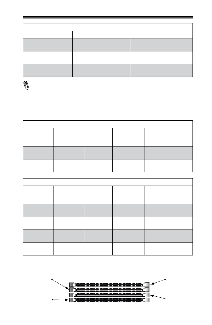
Memory Population Guidelines
Please follow the tables below when populating the X8SIL/X8SIL-F/X8SIL-V.
DDR3 ECC UDIMM Memory
DIMM Slots
per Channel
DIMMs
Populated
per Channel
DIMM Type POR Speeds Ranks per DIMM
(any combination)
2 1 Unbuffered
DDR3 ECC
1066, 1333 Single Rank, Dual
Rank
2 2 Unbuffered
DDR3 ECC
1066, 1333 Single Rank, Dual
Rank
DDR3 ECC RDIMM Memory
DIMM Slots
per Channel
DIMMs
Populated
per Channel
DIMM Type POR Speeds Ranks per DIMM
(any combination)
2 1 Registered
DDR3 ECC
1066, 1333 Single Rank, Dual
Rank
2 1 Registered
DDR3 ECC
1066 Quad Rank
2 2 Registered
DDR3 ECC
1066, 1333 Single Rank, Dual
Rank
2 2 Registered
DDR3 ECC
800* Quad Rank
Slot 1, Channel A
Slot 2, Channel A
Slot 1, Channel B
Slot 2, Channel B
*Note: 1066 RDIMMs running at 800MHz-BIOS will be automatically downgraded to
800MHz speed.

2-14
X8SIL/X8SIL-F/X8SIL-V User's Manual
MAC CO DE
JPI2C
JF1
JPW1
U26
J8 J6J5
J14
1
J13
U61
T-SGPIO1 T-SGPIO2
J24
JLAN2 JLAN1
SPKR1
JBT1
1
JI2C11
JI2C21
LE4
LE2
LE3
LE7
JPT1
1
JPB
JLED1 1
1
JPUSB1
1
JPL1
1
JPL2
JPG1
JD1 1
FAN2 FAN1
FAN5
1
FAN4
FAN3
J16
PCI1
U2
BAR DECO
1-2:ENABLE
2-3:DISABLE
JPL2:LAN2 JPL1:LAN1
2-3:DISABLE
1-2:ENABLE
JPB:BMC
JPI2C:PWR I2C
JD1:Buzz er/Speaker
COM2
FLOPPY
DDR3 1066/1333 UDIMM/RDIMM required
VGA
COM1
USB4
JBT1:CMOS CLEAR
SLOT7 PCI-E X8 GEN2
JPT1:TPM
JL1
LAN1
JPUSB1:B/P USB KE UPWA
1-2:ENABLE
2-3:DISABLE
DIMM2B DIMM2A
USB 10/11
JI2C1/JI2C2
USB2/3
SLOT6 PCI-E X8 GEN2
2-3:Disable
1-2:Enable
JAR:PSU ALARM RST
CPU
JLED1:Power LED
OFF:Disable
ON:Enable
2-3:Disable
1-2:Enable
REV:1.00
X8SIL
DESIGNED IN USA
2-3:DISABLE1-2:ENABLE
:CHASSIS INTRUSION
ON LED LEDPWRHDDNIC1NIC2OH/FFXRSTPWR
I-S A3AT
I-S A4AT I-S A 2AT
I-S A1AT
I-S A0AT
I-S A5AT
SLOT5 PCI-E X4 on X8
SLOT4 PCI 33MHZ
KB/MOUSE
DIMM1B
JPG1: VGA
DIMM1A
JAR
JTPM
JL1
DOM PWR
JPES
1
2-4 Motherboard Installation
All motherboards have standard mounting holes to t different types of chassis.
Make sure that the locations of all the mounting holes for both motherboard and
chassis match. Although a chassis may have both plastic and metal mounting fas-
teners, metal ones are highly recommended because they ground the motherboard
to the chassis. Make sure that the metal standoffs click in or are screwed in tightly.
Then use a screwdriver to secure the motherboard onto the motherboard tray.
Tools Needed
Philips Screwdriver Pan head screws (8 pieces)
Location of Mounting Holes
There are eight (8) mounting holes on this motherboard indicated by the arrows.
Stand Offs (8 pieces)
(Only if needed)
Caution: 1) To avoid damaging the motherboard and its components, please
do not use a force greater than 8 lb/inch on each mounting screw during
motherboard installation. 2) Some components are very close to the mount-
ing holes. Please take precautionary measures to prevent damage to these
components when installing the motherboard to the chassis.

Chapter 2: Installation
2-15
Installation Instructions
Install the I/O shield into the chassis.
Locate the mounting holes on the motherboard. Refer to the layout on the
previous page for mounting hole locations.
Locate the matching mounting holes on the chassis. Install standoffs in the
chassis as needed. Align the mounting holes on the motherboard against the
mounting holes on the chassis.
Install the motherboard into the chassis carefully to avoid damage to mother-
board components.
Insert a Pan head #6 screw into a mounting hole on the motherboard and its
matching mounting hole on the chassis, using the Philips screwdriver.
Repeat Step 4 to insert #6 screws into all mounting holes.
I/O Shield
1
2
3
Stand Off
4
5
6
Make sure that the motherboard is securely placed in the chassis.
7
Note: Image is for illustration
purposes only. Your particular
chassis may be different.

Chapter 2: Installation
2-17
MAC CO DE
JPI2C
JF1
JPW1
U26
J8 J6J5
J14
1
J13
U61
T-SGPIO1 T-SGPIO 2
J24
JLAN2 JLAN1
SPKR1
JBT1
1
JI2C1 1
JI2C2 1
LE4
LE2
LE3
LE7
JPT1
1
JPB
JLED1 1
1
JPUSB1
1
JPL1
1
JPL2
JPG1
JD1 1
FAN2 FAN1
FAN5
1
FAN4
FAN3
J16
PCI1
U2
BAR DECO
1-2:ENABLE
2-3:DISABLE
JPL2:LAN2 JPL1:LAN1
2-3:DISABLE
1-2:ENABLE
JPB:BMC
JPI2C:PWR I2C
JD1:Buz z e r/Speake r
COM2
FLOPPY
DDR3 1066/1333 UDIMM/RDIMM req uired
VGA
COM1
USB4
JBT1:CMOS CLEA R
SLOT7 PCI-E X8 GEN2
JPT1:TPM
JL1
LAN1
JPUSB1:B/P USB KE UPWA
1-2:ENABLE
2-3:DISABLE
DIMM2B DIMM2A
USB 10/11
JI2C1/JI2C2
USB2/3
SLOT6 PCI-E X8 GEN2
2-3:Disable
1-2:Enable
JAR:PSU ALARM RST
CPU
JLED1: Power LED
OFF:Disable
ON:Enable
2-3:Disable
1-2:Enable
REV:1.00
X8SIL
DESIGNED I N USA
2-3:DISABLE1-2:ENABLE
:CHASSIS IN TRUSI ON
ON LED LED
PWRHDD
NIC1NIC2OH/FFXRS T
PWR
I-S A3AT
I-S A4AT I-S A2AT
I-S A1AT I-S A0AT
I-S A5AT
SLOT5 PCI-E X4 on X8
SLOT4 PCI 33MHZ
KB/MOUSE
DIMM1B
JPG1: VGA
DIMM1A
JAR
JTPM
JL1
DOM PWR
JPES
1
ATX PS/2 Keyboard and PS/2
Mouse Ports
The ATX PS/2 keyboard and PS/2
mouse are located next to the Back
Panel USB Ports 0/1 on the mother-
board. See the table at right for pin
denitions.
PS/2 Keyboard/Mouse Pin
Denitions
PS2 Keyboard PS2 Mouse
Pin# Denition Pin# Denition
1 KB Data 1 Mouse Data
2 No Connection 2 No Connection
3 Ground 3 Ground
4 Mouse/KB VCC
(+5V)
4 Mouse/KB VCC
(+5V)
5 KB Clock 5 Mouse Clock
6 No Connection 6 No Connection
VCC: with 1.5A PTC (current limit)
1
2
1. Keyboard (Purple)
2. Mouse (Green)
Keyboard
Mouse

Chapter 2: Installation
2-19
Ethernet Ports
Two Ethernet ports (LAN1/LAN2) are
located next to the VGA port on the IO
Backplane. In addition, an IPMI Dedi-
cated LAN is also located above USB
0/1 ports on the X8SIL-F to provide a
dedicated network connection for IPMI
2.0 support. These ports accept RJ45
type cables.
Notes:
1. The IPMI Dedicated LAN
is for the X8SIL-F only.
2. Please refer to the LED
Indicator Section for LAN
LED information.
LAN Ports
PinDenition
Pin# Denition
1 P2V5SB 10 SGND
2 TD0+ Act LED11
3 TD0- 12 P3V3SB
4 TD1+ 13 Link 100 LED
(Yellow, +3V3SB)
5 TD1- 14 Link 1000 LED
(Yellow, +3V3SB)
6 TD2+ 15 Ground
7 TD2- 16 Ground
8 TD3+ 17 Ground
9 TD3- 88 Ground
(NC: No Connection)
1. LAN1
2. LAN2
3.IPMI Dedicated LAN (X8SIL-
F only)
3
1
2
MAC CO DE
JPI2C
JF1
JPW1
U26
J8 J6J5
J14
1
J13
U61
T-SG PIO1T-SGP IO2
J24
JLAN2 JLAN1
SPKR1
JBT1
1
JI2C1
1
JI2C2 1
LE4
LE2
LE3
LE7
JPT1
1
JPB
JLED1 1
1
JPUSB1
1
JPL1
1
JPL2
JPG1
JD11
FAN2 FAN1
FAN5
1
FAN4
FAN3
J16
PCI1
U2
BAR DECO
1-2:ENABLE
2-3:DISABLE
JPL2:LAN2 JPL1:LAN1
2-3:DISABLE
1-2:ENABLE
JPB:BMC
JPI2C:PWR I2C
JD1:Buzz er/Speaker
COM2
FLOP P Y
DDR 3 1066/1333 U DIMM/RD IMM req uire d
VGA
COM1
USB4
JBT1:CM OS CLEAR
SLOT7 PCI-E X8 GEN2
JPT1:TPM
JL1
LAN1
JPUSB1:B/P USB KE UPWA
1-2:ENABLE
2-3:DISABLE
DIMM2B DI MM2A
USB 10/11
JI2C1/JI2C2
USB2/3
SLOT6 PCI-E X8 GEN2
2-3:Disable
1-2:Enable
JAR:PSU ALARM RST
CPU
JLED1:P ower LED
OFF:Disable
ON:Enable
2-3:Disable1- 2:Ena ble
REV:1.00
X8SIL
DESIG NED IN USA
2-3:DISABLE1-2:ENABLE
:CHASSI S IN TRU SION
ON LED LED
PWRHDD
NIC1NIC2OH/FFXRS T
PWR
I-S A3AT
I-S A4AT I-S A2AT
I-S A1AT
I-S A0AT
I-S A5AT
SLOT5 PCI-E X4 on X8
SLOT4 PCI 33MHZ
KB/MOUSE
DIMM1B
JPG1: VGA
DIMM1A
JAR
JTPM
JL1
DOM PWR
JPES
1

2-30
X8SIL/X8SIL-F/X8SIL-V User's Manual
Serial_Link-SGPIO
PinDenitions
Pin# Denition Pin Denition
1 NC 2 NC
3 Ground 4 DATA Out
5 Load 6 Ground
7 Clock 8 NC
T-SGPIO 0/1 Headers
Two T-SGPIO (Serial-Link General Pur-
pose Input/Output) headers are located
near the SATA connectors on the moth-
erboard. These headers are used to
communicate with the enclosure manage-
ment chip in the system. See the table on
the right for pin denitions. Refer to the
board layout below for the locations of
the headers.
NC: No Connections
A. T-SGPIO 0
B. T-SGPIO 1
C. Alarm Reset
C
A
B
Alarm Reset
If three power supplies are installed and
Alarm Reset (JAR) is connected, the sys-
tem will notify you when any of the three
power modules fail. Connect JAR to a
micro-switch to turn off the alarm that is
activated when a power module fails. See
the table on the right for pin denitions.
Alarm Reset
PinDenitions
Pin Setting Denition
Pin 1 Ground
Pin 2 +5V
MAC CO DE
JPI2C
JF1
JPW1
U26
J8 J6J5
J14
1
J13
U61
T-SGPIO1 T-SGPIO2
J24
JLAN2 JLAN1
SPKR1
JBT1
1
JI2C11
JI2C21
LE4
LE2
LE3
LE7
JPT1
1
JPB
JLED11
1
JPUSB1
1
JPL1
1
JPL2
JPG1
JD1 1
FAN2 FAN1
FAN5
1
FAN4
FAN3
J16
PCI1
U2
BAR DECO
1-2:ENABLE
2-3:DISABLE
JPL2:LAN2 JPL1:LAN1
2-3:DISABLE
1-2:ENABLE
JPB:BMC
JPI2C:PWR I2C
JD1:Buzz er/ Speaker
COM2
FLOPPY
DDR3 1066/1333 UDIMM/RDIMM required
VGA
COM1
USB4
JBT1:CMOS CLEAR
SLOT7 PCI-E X8 GEN2
JPT1:TPM
JL1
LAN1
JPUSB1:B/P USB KE UPWA
1-2:ENABLE
2-3:DISABLE
DIMM2B DIMM2A
USB 10/11
JI2C1/JI2C2
USB2/3
SLOT6 PCI-E X8 GEN2
2-3:Disable
1-2:Enable
JAR:PSU ALARM RST
CPU
JLED1:Power LED
OFF:Disable
ON:Enable
2-3:Disable
1-2:Enable
REV:1.00
X8SIL
DESIGNED IN USA
2-3:DISABLE1-2:ENABLE
:CHASSIS INTRUSION
ON LED LEDPWRHDDNIC1NIC2OH/FFXRSTPWR
I-S A3AT
I-S A4AT I- S A2AT
I-S A1AT
I-S A0AT
I-S A5AT
SLOT5 PCI-E X4 on X8
SLOT4 PCI 33MHZ
KB/MOUSE
DIMM1B
JPG1: VGA
DIMM1A
JAR
JTPM
JL1
DOM PWR
JPES
1

Chapter 2: Installation
2-33
B
A
A. VGA Enable
B. TPM Enable
C. Energy Saving Enable
VGA Enable/Disable
Jumper Settings (JPG1)
Both Jumpers Denition
Pins 1-2 Enabled
Pins 2-3 Disabled
VGA Enable
JPG1 allows you to enable or disable
the onboard VGA connector. The default
position is on pins 1 and 2 to enable
VGA. See the table on the right for
jumper settings.
MAC CO DE
JPI2C
JF1
JPW1
U26
J8 J6J5
J14
1
J13
U61
T-SGPIO1 T-SGPIO2
J24
JLAN2 JLAN1
SPKR1
JBT1
1
JI2C1 1
JI2C2 1
LE4
LE2
LE3
LE7
JPT1
1
JPB
JLED1 1
1
JPUSB1
1
JPL1
1
JPL2
JPG1
JD1 1
FAN2 FAN1
FAN5
1
FAN4
FAN3
J16
PCI1
U2
BAR DECO
1-2:ENABLE
2-3:DISABLE
JPL2:LAN2 JPL1:LAN1
2-3:DISABLE
1-2:ENABLE
JPB:BMC
JPI2C:PWR I2C
JD1:Buzz er/ Speaker
COM2
FLOPPY
DDR3 1066/1333 UDIMM/RDIMM required
VGA
COM1
USB4
JBT1:CMOS CLEAR
SLOT7 PCI-E X8 GEN2
JPT1:TPM
JL1
LAN1
JPUSB1:B/P USB KE UPWA
1-2:ENABLE
2-3:DISABLE
DIMM2B DIMM2A
USB 10/11
JI2C1/JI2C2
USB2/3
SLOT6 PCI-E X8 GEN2
2-3:Disable
1-2:Enable
JAR:PSU ALARM RST
CPU
JLED1:Power LED
OFF:Disable
ON:Enable
2-3:Disable
1-2:Enable
REV:1.00
X8SIL
DESIGNED IN USA
2-3:DISABLE1-2:ENABLE
:CHASSIS INTRUSION
ON LED LEDPWRHDDNIC1NIC2OH/FFXRSTPWR
I-S A3AT
I-S A4AT I-S A2AT
I-S A1AT
I-S A0AT
I-S A5AT
SLOT5 PCI-E X4 on X8
SLOT4 PCI 33MHZ
KB/MOUSE
DIMM1B
JPG1: VGA
DIMM1A
JAR
JTPM
JL1
DOM PWR
JPES
1
TPM Support Enable
JPT1 allows the user to enable TPM
(Trusted Platform Module) support to im-
prove data integrity and system security.
See the table on the right for jumper set-
tings. The default setting is Enabled.
TPM Support Enable
Jumper Settings
Jumper Setting Denition
1-2 (Default) Enabled
2-3 Disabled
Energy Saving Enable
JPES allows the user to enable the en-
ergy-saving feature of this motherboard.
When set to Enabled, the motherboard
will enter Deep S5 Mode. The default
setting is (Normal S5 Mode).Disabled
Energy Saving Enable
Jumper Settings
Jumper Setting Denition
1-2 Enabled
2-3 (Default) Disabled
C
Specyfikacje produktu
| Marka: | Supermicro |
| Kategoria: | płyta główna |
| Model: | MBD-X8SIL-O |
| Rodzaj zasilania: | ATX |
| Szerokość produktu: | 246 mm |
| Głębokość produktu: | 246 mm |
| Ilość portów Ethernet LAN (RJ-45): | 2 |
| Zakres temperatur (eksploatacja): | 10 - 35 °C |
| Zakres wilgotności względnej: | 8 - 90 % |
| Karta graficzna: | Matrox G200eW |
| Liczba portów USB 2.0: | 3 |
| Producent procesora: | Intel |
| Liczba gniazd pamięci: | 4 |
| Maksymalna pojemność pamięci: | 32 GB |
| Gniazdo procesora: | LGA 1156 (Socket H) |
| Rodzaj płyty: | micro ATX |
| Układ płyty głównej: | Intel® 3400 |
| Ilość gniazd USB 2.0: | 2 |
| Liczba portów PS/2: | 2 |
| Zawiera sterowniki: | Tak |
| Kontroler LAN: | Intel® 82574L |
| Funkcja Wake-On-LAN: | Tak |
| Złącze wentylatora: | Tak |
| Liczba portów VGA (D-Sub): | 1 |
| Cechy sieci: | 10/100/1000 |
| Korekcja ECC: | Tak |
| Pamięć karty graficznej podsystemu graficznego: | 16 MB |
| Rozmiar pamięci BIOS: | 32 Mbit |
| Szeregowe porty komunikacyjne: | 1 |
| Napięcie pamięci: | 1.5 V |
| Ilość gniazd SATA: | 4 |
| Sloty PCI: | 1 |
| PCI Express x8 slots: | 2 |
Potrzebujesz pomocy?
Jeśli potrzebujesz pomocy z Supermicro MBD-X8SIL-O, zadaj pytanie poniżej, a inni użytkownicy Ci odpowiedzą
Instrukcje płyta główna Supermicro

19 Grudnia 2024
5 Grudnia 2024
7 Października 2024
7 Października 2024
7 Października 2024
4 Października 2024
4 Października 2024
4 Października 2024
4 Października 2024
4 Października 2024
Instrukcje płyta główna
- płyta główna Gigabyte
- płyta główna Asus
- płyta główna MSI
- płyta główna NZXT
- płyta główna Biostar
- płyta główna Asrock
- płyta główna Sharkoon
- płyta główna ECS
- płyta główna Evga
- płyta główna Intel
- płyta główna Foxconn
- płyta główna Advantech
- płyta główna Elitegroup
- płyta główna EPoX
Najnowsze instrukcje dla płyta główna

8 Kwietnia 2025
8 Kwietnia 2025
3 Kwietnia 2025
3 Kwietnia 2025
3 Kwietnia 2025
3 Kwietnia 2025
2 Kwietnia 2025
2 Kwietnia 2025
2 Kwietnia 2025
30 Marca 2025