Instrukcja obsługi Speco Technologies SG519
Speco Technologies
magnetowid
SG519
Przeczytaj poniżej 📖 instrukcję obsługi w języku polskim dla Speco Technologies SG519 (2 stron) w kategorii magnetowid. Ta instrukcja była pomocna dla 12 osób i została oceniona przez 2 użytkowników na średnio 4.5 gwiazdek
Strona 1/2
SecureGuard® Server
+
Faceplate
(Set of 2 keys included)
+
Rack Ears (included)
Before operating the unit, please read this user’s guide thoroughly and
retain it for future reference.
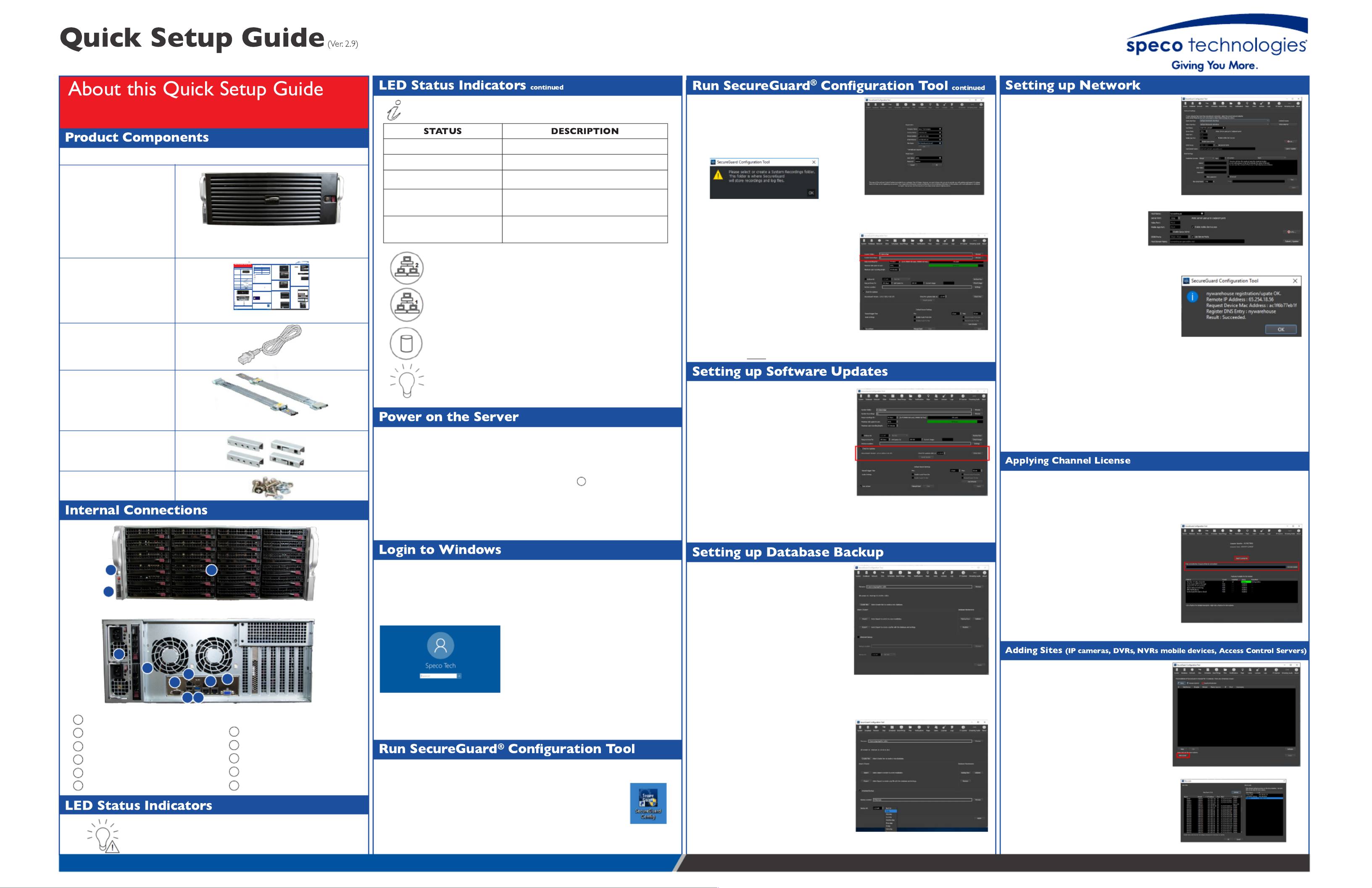
Speco Technologies SecureGuard® Server - Model: SG519 (4U)
The following components are included:
QTY: 1
*Server comes with the rack ears mounted*
Power Cable
QTY: 2
Server Rails
(Instruction Manual
Included)
QTY: 1 pair
Rack Bracket Adapters
Hardware
Power Failure LED:
Flashing LED indicates power supply failure.
Information LED:
NIC2 Activity LED:
Indicates network activity on LAN 2 when flashing.
NIC1 Activity LED:
Indicates network activity on LAN 1 when flashing.
HDD Activity:
Indicates drive (SAS/SATA, SCSI, and/or DVD-ROM) activity when
flashing.
Power Status:
Indicates power is being supplied to the power supply units.
•If prompted to select or create a
Systems Recordings folder, point to the
storage drive where the recordings will be
stored (Recordings D:). Otherwise move
on to the next step. See Image 3.
•Upon opening the Configuration Tool,
you will need to register your SecureGuard®
installation. This information is mandatory
and will be included in e-mail notifications
if utilized. The default username admin
and default password to access admin
the SecureGuard® Configuration Tool.
See Image 4.
•At the “System” tab, ensure “System
Recordings” file path is pointing to the
storage drives. See Image 5.
Image 3 Image 4
Image 5
Note: Server must be connected
to the internet to search and
download updates
Note: It is HIGHLY recommended
that you backup your database to
a separate drive and NOT to your
C: drive.
•SecureGuard
® will be set to check for
updates on a daily basis. The time to
check for updates can be modified by
simply changing the hour, minute, and
meridiem. You can manually check for
updates by clicking “Check Now”.
See Image 6.
•The “Database” tab is where you import
or export settings and back up, restore, or
validate the SecureGuard® database.
.See Image 7
•It is recommended that you back up your
database on a scheduled basis. If your
database gets corrupted, you will be
able to restore to a point where the
database was stable. To setup up a
scheduled database backup, first check
the box next to “Scheduled Backup”.
•Choose where you would like to backup your database by clicking “Browse”.
•Adjust the time’s hour, minute, and
meridiem to specify what time the
database will be backed up. And lastly,
select whether the database will be
backed up on a daily basis or weekly
basis. Once completed, click “Apply”.
See Image 8.
Image 6
Note: For servers with Dual Network
Interface Cards, it is highly advisable
that the camera and the client connection
network traffic be kept separate.
•To disable the scheduled update check, uncheck the box next to “Enable Automatic
Updates”. Click “Apply” to confirm changes.
Image 7
Image 8
•If the server name isn’t currently registered
with Speco’s DDNS server, then the
registration will be successful. If it fails, use a
different name for the “Host Name”.
See Image 11.
Image 11
Image 12
Image 9
Image 10
• By default, the server uses ports 7312 & 7313 for network communication.
Note: To avoid network conflicts with devices that also use the server default
ports 7312, 7313,and 7314 the option of changing the port numbers is
available through the Configuration Tool. The servers come shipped with an
inbound rule for Window’s firewall that allows communication on the server
default ports. If the server default ports are changed, please ensure the
existing inbound rule is updated, or create a new inbound rule permitting
communication on the new server port values.
•The “Sites” tab is where sites (IP cameras,
DVRs, NVRs, mobile devices, and Access
Control Devices) can be added, deleted
or updated. There are two methods of
adding sites to the server. The first method
uses “Site Locate” which automatically
scans the Local Area Network for IP
cameras and select, DVRs , NVRs
and hybrid DVRs. See Image 13. Image 13
Image 14
•Clicking on “Site Locate”, will open
the “Site Locate” window and start
scanning the local area network
for your devices. You can rescan the
network by clicking on “Refresh”.
See Image 14.
Quick Setup Guide
QTY: 1
•Please follow the proper power ON procedures to avoid damaging the server.
•Connect all necessary components, e.g. monitor and cameras, before powering
the server.
•Power ON the server by depressing the Power Switch ( ) to boot up the server.
WARNING: To reduce the risk of database corruption due to power loss,
Speco strongly urges use of an uninterruptible power supply with our
SecureGuard® servers.
1
• After boot up, at the Windows login screen, you will see that the default user account
is “Speco Tech”. There is no password associated with the default account. It is
to set a password after logging into the Windows home screen for highly advisable
the first time. See Image 1.
Image 1
Note: The server comes pre-loaded with SecureGuard® Server software.
•At the Windows Desktop home screen, run the SecureGuard®
Configuration Tool to setup the server by double clicking on the
SecureGuard®
Configuration Tool icon. See Image 2.
Image 2
WARNING: Please store your password
in a safe location. Speco Technologies
will not be able to assist you in
recovering a lost password.
Note: The default timezone on the servers
is set to (UTC-05:00) Eastern Time (US &
Canada).
•In the “Network” tab, for “Client Interface”
select the network adapter that remote
client(s) will connect to. For “Video Interface”
select the network adapter that the camera(s)
will connect to. See Image 9.
•Your SecureGuard® Server initially comes with a free 32-channel license. If your
server installation exceeds 32-channels, you will need to apply a channel license
in order to add the remaining total. This license is provided by Speco.
•Go to the “License Tab” and either enter your
activation code (requires an internet
connection) or import your license by pressing
“Import License File” and selecting your
license file. See Image 12.
•Your license, along with the channel count,
will then be displayed in the list below.
Secu re Gu ard ® Se rver
+
Fac ep lat e
(Set o f 2 k ey s in c lu de d)
+
Rack E ars
Before operati ng t he u nit , ple sae read th is user’s g ui de t horoug h ly and
retain it for fu ture referen ce.
Product Compone nts
LED Status Indicators
Quick Setup Guide
Speco Tec hnologies SecureG uard
®
Server -
Model : SG515(4U)
The fol lo wing c om p on en ts a re in cl ud ed :
QT: 1
*Server c om e s wit h th e ra c k ea rs m ou nt ed *
Power Ca ble
QT: 2
Server R ail s(Instru ct ion M an ua l
Incl u d e d)
QT: 1 pa ir
Rack B rac k et Ada pte rs
Hardware
Internal Connec tions
Rear Vie w
6
7
8
9
10
1
Power S witc h
2
Reset Swit ch & LE D St atu s In di c ato rs
3
3.5” HDD Bay x24
4
AC Inpu ts fo r R edu n dan t Po wer S up ply
5
2.5” HDD Bay x2
DB9 COM P ort
IPMI I nt erf ac e
USB 2.0 x4
Gig a bi t E th ern e t LAN P orts x2
VGA Ou tp ut
Power F ai lu re LED:
Flash in g LED i ndi c ate s po wer su ppl y fai lu re.
Inform a tio n LED:
STATUS DESCRIPTION
Contin u ou sly ON & red Overhe at co nd it ion h as o cc u red .
Blin ki ng re d (1 Hz) Fan fai lu re .
Blin ki ng re d (. 25 Hz) Power f ail u re.
Solid bl ue
Local UID h as b ee n ac ti vated to
loca te th e server in a rac k
environ m ent .
Blin ki ng b lu e (3 00 m se c)
Rem ot e UI D ha s be en a ct ivate d
to lo ca te th e server from a
remo te lo c ati on .
NIC2 Ac ti vity LED:
Indic a tes ne twork a c tivit y on LAN 2 whe n fl ashi ng .
NIC1 Ac ti vity LED:
Indic a tes ne twork a c tivit y on LAN 1 whe n fl ashi ng .
HDD Activity :
Indic a tes drive (SAS /SATA, S CSI, an d/or DVD-RO M) a c tivit y when
flashi n g .
Power S ta tu s:
Indic a tes powe r is b ei ng su ppl ie d t o th e p ower sup ply u n its.
LED Status Indicators
1
Fron t Vi ew ( With ou t F a ce pl ate )
2
3
45
6
7
8
9 10
Run SecureGuard
®
Conguration Tool Setting up Network
• Whe n prom p te d, en te r t he
defau lt u sern am e and a dm i n
defau lt pa ssword to acce ss adm i n
the Se cu re Gu ard
®
Confi g u rat ion
Tool. Se e Image 3.
• At the “Sy ste m ” tab , e nsu re
“Syste m R ec ord in g s” fi le
pat h i s po in ti ng to th e
storag e dri ves. Se e Imag e 4 .
Image 3
Image 4
Setting up Software Upda tes
Setting up Databa se Backup
No te: Se rver m u st be c on ne ct ed t o t he i nt ern et to sea rc h and d ownl oad u pda te s
No te: It is HIGHLY rec om m en de d th at yo u bac k u p y ou r d ata ba se t o a sep arat e
drive an d NO T to yo ur C: d rive.
•Secu re G u a rd
®
will b e set
to c he ck for up dat es o n a
daily b asis. The tim e t o c h ec k
for up dat es ca n be m od ifi ed
by sim p ly c ha ng in g th e ho ur,
min ut e, an d m eri die m . You c an
man ua ll y ch ec k f or u pd ate s
by c li ck i ng “Che ck N ow”. S ee
Image 5.
•The “Databa se” ta b i s whe re yo u
imp ort or e xport set tin g s an d b ac k up ,
restore , o r vali dat e th e S ec u reG u ard
®
datab ase. Se e Image 6 .
•It is rec o m m en de d t ha t y ou b ac k u p
your dat ab ase on a sch ed ul ed ba sis.
If yo ur dat aba se g e ts c orru pt ed , y ou
will be a ble t o re sto re t o a p oin t whe re
the dat aba se was stab le . To se tu p up a
sched ul ed da ta base ba c ku p, fi rst c h ec k
the box n ext t o “Sc h ed ul ed Ba ck u p”.
•Choose wh ere y ou wou ld li ke t o b ac k up y ou r da ta base by c li c ki ng “Bro wse”.
•Adjust t he t im e ’s ho ur, m i nu te , a nd
meri di em t o spec if y what ti m e th e da-
tabase will b e b ac k ed u p. And la stly ,
selec t whet he r t he d ata base wil l b e
back e d u p on a dai ly ba sis o r wee k ly
basis. O nc e c om pl et ed , c l ic k “Apply ”.
See Image 7.
Adding Sites (IP camera s, DVRs, NVRs)
Image 5
No te: F or servers wi th Dua l Ne twork
Inte rfac e Card s, it i s hig h ly a dvisa bl e
that th e ca m era an d th e cl ie nt c on ne c ti on
network traf fic b e ke pt sep ara te .
•To disable t he sc he du le d u pd at e c h ec k , un c he ck th e b ox ne xt to “En ab le
Aut om at ic Upd at es”. Cli c k “Apply ” to c on firm ch an g es.
Image 6
Image 7
• If th e se rver n am e i sn’t c urre nt ly
reg iste red with S pe co ’s DDN S
server, th en th e reg ist rati on wil l b e
suc ce ssful . I f i t f ail s, u se a d iff ere nt
nam e f or t he “Host N am e ”. S ee
Image 10.I mage 10
Image 8
Image 9
• By de fa ul t, th e server u ses p ort s & f or n et work c om m u ni c ati on 7312 7313
No te: To a void ne twork c on fl ic ts wi th de vice s th at a lso u se th e server d ef a
7312 7313 and , the o pti on o f c ha ng in g th e port n um b ers i s avai lab le th ro
Config ura ti on Tool. The ser vers co m e shi ppe d with an i nb ou nd ru le fo r Wi
firewall t ha t a ll ows co m m un ic a tio n on th e server de fau lt po rts. If t he se rve
ports are c h an g e d, pl ea se e nsu re th e existi ng in bo un d rul e is u pd ate d, o
new in bo un d rul e pe rm itt in g c om m u ni ca tio n on th e n ew ser ver po rt val u
• The “Site s” tab i s whe re si te s (IP c am e ras, DVRs, an d N VR s) c an be a dd ed
del et ed or up dat ed . The re are t wo m e th ods o f a ddi ng sit es to th e server.
me th o d “Si te Lo ca t e” u se s which a ut om at ic al ly sc an s th e Loca l Area
for o nl y IP c am e ras. See . Image 11
Method 1 : Aut o Detect
Method 2 : M anual
Image 11
Image 12
Image 13
• Click in g on “Sit e Loc ate ”, wil l
open th e “Sit e Lo ca te ” wind ow
and st art sca nn in g th e loc al a rea
network for IP c am er as. You ca n
rescan t he n et work bY cl ic k in g on
“Refresh ”. Se e Image 12 .
• To add a n IP c am er a t o t he
server, do ub le c li ck o n th e IP
cam era t o b rin g up th e “Sit e
Sett in g s” win dows fo r t he IP
cam era . E n sure th e valu es f or a ll
the fie ld s are ac c u rate a nd th en
clic k “OK”. Se e Im ag e 1 0.
• The IP c am e ras wil l n ow b e
listed u nd er “Site s to ad d” li st.
• Contin u e t o rep eat t hi s proc e ss
for th e rem a in in g IP c am e ras th at
must be ad de d To th e server. On c e
com pl et e, c lic k o n “OK” to exit
the “Site Loc a te” win do w. The
cam era s th at were a dde d to th e
“Sites t o a dd” l ist will no w be m ad e
availab le in t he “Sit es” ta b. Cli ck
on “Appl y” t o c om p le te ad di ng th e
sites to t he server. S ee . Image 13
Quic k S et up G ui de
QT: 1
Power on the Server
• Plea se f ol low t he p rope r p ower ON pr oc ed ure s to avoi d d am ag in g th e server.
• Conne c t a ll ne c essary c om p on en ts, e. g . po wer c ab le (s), n et work c ab le (s), m on it or
an d c am e ras, be for e p oweri ng t he serve r.
• Power O N th e server by de pre ssing t he P ower Swit ch ( ) to bo ot up th e server.
WARNING : To re duce th e ri sk o f da t a ba se co rruptio n du e t o p o w er lo ss,
S pe co stro ng ly u rg es u se o f a n un inte rruptibl e p o w er suppl y w ith o u r
S ecureG ua rd
®
servers.
1
Login to Windows
• After b oot u p, at th e Win dows l og in scre en , yo u will see t ha t t he d efa ul t u ser
acc o un t is There i s associated with t he “S pe co Tech”. n o pa ssword
def au lt ac c ou nt . It i s to set a password aft er log g ing i nt o t he hig h ly a dvisa bl e
Wind ows ho m e scre en f or t he fi rst t im e . S ee Imag e 1 .
Image 1
No te: The server co m es p re-l oa ded wit h Se cu re Gu ard
®
Server so ftware .
• At the Win dows De skt op ho m e scre en , run t he S ec ure G ua rd®
Confi g urat io n Too l t o setu p th e se rver b y dou bl e cl ic k in g on
the S ec u reG ua rd
®
Confi g u rat ion Too l i c on. S ee Image 2.
Image 2
No te : DO N O T store rec ord in g s o n th e ha rd d rive ded ic at ed fo r th e op era tin g syste m .
Run SecureGuard® C onguration Tool
WARNING: Ple ase sto re yo ur password
in a safe l oc ati on . S pe co Techn o l o g ie s will
no t be a b le to a ssist yo u in reco veri ng a lo st
pa ssword.
No te: The de fa ul t t im e zo ne o n th e se rvers is set
to (UTC-05:00) E ast ern Tim e (US & Can ada ).
Speco Tech
•In th e “N et work ” tab , fo r “Cli-
ent Int erf ac e” se le ct th e n et work
adapt er th at rem o te c lie n t(s) wil l conn e ct to . Fo r “Vid eo In te rfac e ”
selec t th e n e twork a dap te r th at
the ca m era (s) will c on n ec t to. Se e
Image 8.
• To reg i ster th e server wi th Sp ec o’s
Free DDNS , en sure th e “En abl e
Spec o DDNS” c h ec k box i s
selec te d, an d e n te r a na m e f or t he
server in th e “Host N am e ” fie ld
the n c lic k o n “Sub m it/Up dat e”.
See Image 9 .
1706-035
Rev. 8/22/17
Note: SecureGuard® servers come with independent hard drive(s) for the storage recordings and the
operating system. Do not store recordings in the hard drive dedicated for the operating system.
** IT IS STRONGLY RECOMMENDED THAT THE
ADMIN PASSWORD BE CHANGED TO ENSURE
THE SECURITY OF YOUR INSTALLATION. •To register the server with Speco’s
Free DDNS, ensure the “Enable
Speco DDNS” checkbox is
selected, and enter a name for the
server in the “Host Name” field then click on “Submit/Update”. See Image 10.
Continuously ON & red Overheat condition has been met.
Blinking red (1 Hz) Fan failure.
Blinking red (.25 Hz) Power failure.
Solid blue Local UID has been activated to
locate the server in a rack environment.
Blinking blue (300 msec) Remote UID has been activated to locate the
server from a remote location.
Rear View
6
7
8
9
10
11
1Power Switch
2Reset Switch & LED Status Indicators
33.5” HDD Bays x24
4AC Inputs for Redundant Power Supply
52.5” HDD Bay x2
DB9 COM Port
IPMI Interface x1
USB 2.0 x2
USB 3.0 x2
Gigabit Ethernet LAN ports x2
VGA Output
1
Front View (Without Faceplate)
2
3
4
5
6
7
8 9
10 11
Rev. 4/26/21

•Once the client software has been downloaded, start the installation by running the
executable file.
•Uncheck the components you don’t wish to install on the client computer.
This option is limited to the following components:
• SecureGuard® Streaming Audio App
• SecureGuard® Player
• Start Menu Shortcuts
• Desktop Icon
Components deemed necessary for the operation
of SecureGuard® Client cannot be unchecked.
Click on “Next” to proceed. See Image 27.
200 New Highway
Amityville, NY 11701
1.800.645.5516
specotech.com
Speco Technologies is constantly developing and improving products.
We reserve the right to modify product design and specifications without
notice and without incurring any obligation. Rev. 4/26/21
•To set up a recording schedule, click on the “Schedules” tab.
•Next to “Action:” select the type of recording (Continuous, Motion, or Sensor)
by clicking on the button (radio button) next to it.
•The schedule grid is made up of rows and columns. The rows pertain to the days
of the week (Mon-Sun), and the columns pertain to the hours of a day (00HR-23HR).
•The cells inside the schedule grid can be colored in based on the type of recording
selected. The color representation is
as follows: for , Green Continuous
for , for , Blue Motion Orange Sensor
and White for . To color No Recording
in the grid, hold down the mouse button
and drag the mouse cursor over the grid.
. See Image 23
•To set the entire schedule to a single
recording type, click on the white box
located in the top-left most corner of the
grid. See Image 24.
Note: By default, the server comes loaded
with 3 user accounts: Admin, User, & Guest.
•Go to the “Users” tab. Here you can add,
edit, or delete users, manage user site
privileges through roles and permissions.
•The “Add User” window will pop up.
See Image 26.
•If desired, you can copy settings from another
to streamline the process. This will include Role
Information, Site/Channel permissions, and
Client settings such as layouts, tours, etc.
•To add users, click on “Add User”. See Image 25.
•The “admin” account will have full access to all
sites and features and cannot be deleted.
•Enter the new user credentials and a name.
•If applicable, select a “User Role” based on the level of access you wish the user to
have. An “Administrator” role has full access to the system and sites. The “User” and
“Guest” roles have limited access, but the permissions can be modified.
•Users and Guests can also be restricted to specific sites and channels by toggling
the boxes next to the sites and channels.
Note: A customized role can be created to
meet varying levels of access control.
•Click on “OK” to exit the “Add User” window,
and click on “Apply” in the “Users” tab to add
the user(s) to the system.
Speco Technologies SecureGuard® Server - Model: SG519 (4U)
•Once the installation is complete, the SecureGuard® Client user login window
will open. If not, run the application by double clicking on the SecureGuard®
Client desktop icon.
•At the user login window, enter the server address. The server address can be the
IP address of the server or the DDNS name. If using the latter, please make sure
“Use DDNS” checkbox is checked and then click on “OK”. See Image 29.
•Once logged in, the SecureGuard® Client
Welcome window will pop up. Click “OK”
to proceed. See Image 30.
•Next, the User Settings window
will pop up. Here the sites that were
added to the server will be listed
under Saved Sites. See Image 31.
•In order to view the sites, they need to be placed in a group. To start off, a default
group has already been created named Group. To add the sites , click onGroup
“Apply.” The “Apply” button will be grayed out, indicating the sites have been added
to . Click on “Close” to exit the User Settings window. Group See Image 32.
•The Open Group window will pop up listing
all the groups and sites. Select and click Group
on “OK” to begin viewing the sites added to
. Group See Image 33 and Image 34.
Note: Download the SecureGuard® Client from Speco Technologies website
at www.specotech.com
•Select the destination folder where SecureGuard®
Client will be installed by clicking on “Browse”,
or use the suggested destination folder which
SecureGuard® Client will create. Click on “Install”
to proceed. See Image 28.
•The second method of adding sites to the server is by
manually entering the site information. This method must be
used when adding mobile devices as well as DVRs, NVRs,
and hybrid DVRs not scanned in “Site Locate”. To enter site
information manually, click on “New” in the “Sites” tab to
bring up the “Site Settings” window. See Image 16.
•Fill in the values for all the fields, and verify the accuracy
of the information by clicking on “Check Site”.
Note: A “Check Site” should always be performed
when adding a DVR/NVR/Hybrid. Doing so will
confirm the number of channels on the site in order
to toggle PTZ control for the channels and, if needed,
restrict users from specific channels in the client.
•The channel boxes under PTZ Control will be consistent with
the number of channels on the DVR, NVR, or Hybrid. Per
form another “Check Site”. If the connection is successful,
click “OK” on both windows. See Image 19.
•Correct any information by clicking “Fix”. See Image 17.
•Finally click on “Apply” to add the site(s) to the server.
See Image 22.
•Click “OK”. See Image 18.
•If a “Check Site” connection is successful, you can preview
the incoming video from the site (and channels, if applicable).
If you’re connecting to a recorder, use the dropdown next to
“Channel” to select the channel you would like to preview.
This can assist you in better identifying the camera you’re
adding to your installation and naming the site.
See Image 20 and Image 21.
Image 16
Image 17
Image 18
Image 19
Image 20
Image 21
Image 22
Image 23
Image 25
Image 26
Image 29
Image 30
Image 34
Image 33
Image 31
Image 32
Image 24
•Once the schedule and recording type
has been set, associate the schedule with
individual sites (IP cameras, DVRs, NVRs)
by moving over the sites listed under
“Available Site…” to “Sites using schedule
…” by clicking on
•Click on “Apply” to save the schedule.
Image 27
Image 28
•The devices will now be listed under “Sites to add” list.
•Continue to repeat this process for the remaining
IP Cameras that must be added to the server.
Once complete, click on “OK” to exit the “Site
Locate” window. The cameras that were added to
the “Sites to add” list will now be made available
in the “Sites” tab. Click on “Apply” to complete
adding the sites to the server. See Image 22. Image 15
•To add a site to the server, double click on the device to bring up the “Site Settings”
window. Ensure the values for all the fields are accurate, enter the camera’s login
credentials and verify the accuracy of the information by clicking on “Check Site”.
If the connection is successful, click “OK”.
See Image 15.
Specyfikacje produktu
| Marka: | Speco Technologies |
| Kategoria: | magnetowid |
| Model: | SG519 |
Potrzebujesz pomocy?
Jeśli potrzebujesz pomocy z Speco Technologies SG519, zadaj pytanie poniżej, a inni użytkownicy Ci odpowiedzą
Instrukcje magnetowid Speco Technologies

17 Września 2024
16 Września 2024
15 Września 2024
14 Września 2024
14 Września 2024
14 Września 2024
13 Września 2024
13 Września 2024
12 Września 2024
12 Września 2024
Instrukcje magnetowid
- magnetowid Sony
- magnetowid Samsung
- magnetowid Tenda
- magnetowid Motorola
- magnetowid TP-Link
- magnetowid Philips
- magnetowid Bosch
- magnetowid Hikvision
- magnetowid EZVIZ
- magnetowid Panasonic
- magnetowid Canon
- magnetowid Reolink
- magnetowid TRENDnet
- magnetowid Toshiba
- magnetowid D-Link
- magnetowid Imou
- magnetowid Grundig
- magnetowid Tripp Lite
- magnetowid Moxa
- magnetowid Synology
- magnetowid JVC
- magnetowid Linksys
- magnetowid Digitus
- magnetowid Dahua Technology
- magnetowid DataVideo
- magnetowid Vivotek
- magnetowid Navitel
- magnetowid AirLive
- magnetowid Planet
- magnetowid Aiwa
- magnetowid LevelOne
- magnetowid Axis
- magnetowid Lorex
- magnetowid Milesight
- magnetowid Abus
- magnetowid Elro
- magnetowid Ubiquiti Networks
- magnetowid QNAP
- magnetowid Hitachi
- magnetowid Ernitec
- magnetowid Technaxx
- magnetowid Hanwha
- magnetowid Grandstream
- magnetowid Blackmagic Design
- magnetowid Foscam
- magnetowid Monacor
- magnetowid Daewoo
- magnetowid Kunft
- magnetowid UniView
- magnetowid A.C.Ryan
- magnetowid Aristona
- magnetowid Acti
- magnetowid Sylvania
- magnetowid Magnum
- magnetowid GeoVision
- magnetowid Evga
- magnetowid Seagate
- magnetowid Provision ISR
- magnetowid Digital Watchdog
- magnetowid DirecTV
- magnetowid Skytronic
- magnetowid Magnavox
- magnetowid Inkovideo
- magnetowid Pentatech
- magnetowid Mach Power
- magnetowid Avigilon
- magnetowid IDIS
Najnowsze instrukcje dla magnetowid
2 Kwietnia 2025
30 Marca 2025
29 Marca 2025
13 Marca 2025
13 Marca 2025

12 Marca 2025
25 Lutego 2025
25 Lutego 2025
23 Lutego 2025

17 Lutego 2025