Instrukcja obsługi Sharp PN-V602A
Przeczytaj poniżej 📖 instrukcję obsługi w języku polskim dla Sharp PN-V602A (60 stron) w kategorii monitor. Ta instrukcja była pomocna dla 7 osób i została oceniona przez 2 użytkowników na średnio 4.5 gwiazdek
Strona 1/60

PN-V602A
LCD MONITOR
OPERATION MANUAL

IMPORTANT:
To aid reporting in case of loss or theft, please record the
product’s model and serial numbers in the space provided.
The numbers are located in the rear of the product.
Model No.:
Serial No.:
U.S.A. ONLY
FOR CUSTOMERS IN U.K.
IMPORTANT
The wires in this mains lead are coloured in accordance with the following code:
GREEN-AND-YELLOW: Earth
BLUE: Neutral
BROWN: Live
As the colours of the wires in the mains lead of this apparatus may not correspond with the coloured markings identifying the
terminals in your plug proceed as follows:
•ThewirewhichiscolouredGREEN-AND-YELLOWmustbeconnectedtotheterminalintheplugwhichismarkedbythe
letter or by the safety earth Eorcolouredgreenorgreen-and-yellow.
•ThewirewhichiscolouredBLUEmustbeconnectedtotheterminalwhichismarkedwiththeletterN or coloured black.
•ThewirewhichiscolouredBROWNmustbeconnectedtotheterminalwhichismarkedwiththeletterL or coloured red.
Ensurethatyourequipmentisconnectedcorrectly.Ifyouareinanydoubtconsultaqualiedelectrician.
“WARNING: THIS APPARATUS MUST BE EARTHED.”

3E
IMPORTANT INFORMATION
WARNING: TOREDUCETHERISKOFFIREORELECTRICSHOCK,DONOTEXPOSETHISPRODUCT
TORAINORMOISTURE.
RISKOFELECTRIC
SHOCK
DONOTOPEN
CAUTION
CAUTION: TOREDUCETHERISKOFELECTRIC
SHOCK,DONOTREMOVECOVER.
NOUSER-SERVICEABLEPARTS
INSIDE.
REFERSERVICINGTOQUALIFIED
SERVICEPERSONNEL.
Thelightningashwitharrowheadsymbol,within
anequilateraltriangle,isintendedtoalertthe
user to the presence of uninsulated “dangerous
voltage” within the product’s enclosure that may
beofsufcientmagnitudetoconstituteariskof
electric shock to persons.
The exclamation point within a triangle is
intended to alert the user to the presence of
important operating and maintenance (servicing)
instructions in the literature accompanying the
product.
WARNING:
FCCRegulationsstatethatanyunauthorizedchangesormodicationstothisequipmentnotexpresslyapprovedbythe
manufacturercouldvoidtheuser’sauthoritytooperatethisequipment.
NOTE:
ThisequipmenthasbeentestedandfoundtocomplywiththelimitsforClassAdigitaldevice,pursuanttoPart15ofthe
FCCRules.Theselimitsaredesignedtoprovidereasonableprotectionagainstharmfulinterferencewhentheequipment
isoperatedinacommercialenvironment.Thisequipmentgenerates,uses,andcanradiateradiofrequencyenergyand,if
not installed and used in accordance with the instruction manual, may cause harmful interference to radio communications.
Operationofthisequipmentinaresidentialareaislikelytocauseharmfulinterferenceinwhichcasetheuserwillberequired
to correct the interference at his own expense.
ThisproductutilizesaCRcoinLithiumbatterywhichcontainsaPerchloratematerial.
Special handling for this material may apply,
Californiaresidents,Seewww.dtsc.ca.gov/hazardouswaste/perchlorate/
Others,consultlocalenvironmentalofcers.
U.S.A. ONLY

4
E
IMPORTANT INFORMATION (Continued)
Information on the Disposal of this Equipment and its Batteries
IFYOUWISHTODISPOSEOFTHISEQUIPMENTORITSBATTERIES,DONOTUSETHEORDINARYWASTEBIN,
ANDDONOTPUTTHEMINTOAFIREPLACE!
UsedelectricalandelectronicequipmentandbatteriesshouldalwaysbecollectedandtreatedSEPARATELYinaccordance
with local law.
Separatecollectionpromotesanenvironment-friendlytreatment,recyclingofmaterials,andminimizingnaldisposalof
waste.IMPROPERDISPOSALcanbeharmfultohumanhealthandtheenvironmentduetocertainsubstances!TakeUSED
EQUIPMENTtoalocal,usuallymunicipal,collectionfacility,whereavailable.
RemoveUSEDBATTERIESfromequipment,andtakethemtoabatterycollectionfacility;usuallyaplacewherenew
batteries are sold.
If in doubt about disposal, contact your local authorities or dealer and ask for the correct method of disposal.
ONLYFORUSERSINTHEEUROPEANUNION,ANDSOMEOTHERCOUNTRIES;FORINSTANCENORWAYAND
SWITZERLAND:Yourparticipationinseparatecollectionisrequestedbylaw.
Thesymbolshownaboveappearsonelectricalandelectronicequipmentandbatteries(orthepackaging)toremindusers
ofthis.If‘Hg’or‘Pb’appearsbelowthesymbol,thismeansthatthebatterycontainstracesofmercury(Hg)orlead(Pb),
respectively.
UsersfromPRIVATEHOUSEHOLDSarerequestedtouseexistingreturnfacilitiesforusedequipmentandbatteries.
Batteriesarecollectedatpointsofsale.Returnisfreeofcharge.
IftheequipmenthasbeenusedforBUSINESSPURPOSES,pleasecontactyourSHARPdealerwhowillinformyouabout
take-back.Youmightbechargedforthecostsarisingfromtake-back.Smallequipment(andsmallquantities)mightbetaken
backbyyourlocalcollectionfacility.ForSpain:Pleasecontacttheestablishedcollectionsystemoryourlocalauthorityfor
take-backofyourusedproducts.

5E
Thank you for your purchase of a SHARP LCD product. To ensure safety and many years of trouble-free operation of your
product, please read the Safety Precautions carefully before using this product.
SAFETY PRECAUTIONS
Electricity is used to perform many useful functions, but it can also cause personal injuries and property damage if improperly
handled. This product has been engineered and manufactured with the highest priority on safety. However, improper use can
result in electric shock and/or re. In order to prevent potential danger, please observe the following instructions when installing,
operating and cleaning the product. To ensure your safety and prolong the service life of your LCD product, please read the
following precautions carefully before using the product.
1. Read instructions — All operating instructions must be read and understood before the product is operated.
2. Keep this manual in a safe place — These safety and operating instructions must be kept in a safe place for future
reference.
3. Observe warnings — All warnings on the product and in the instructions must be observed closely.
4. Follow instructions — All operating instructions must be followed.
5. Cleaning — Unplug the power cord from the AC outlet before cleaning the product. Use a dry cloth to clean the product. Do
not use liquid cleaners or aerosol cleaners.
6. Attachments — Do not use attachments not recommended by the manufacturer. Use of inadequate attachments can result
in accidents.
7. Water and moisture — Do not use the product near water. Do not install the product in a place where water may splash onto
it. Be careful of equipment which drains water such as an air-conditioner.
8. Ventilation — The vents and other openings in the cabinet are designed for ventilation.
Do not cover or block these vents and openings since insufcient ventilation can cause overheating and/or shorten the life
of the product. Do not place the product on a sofa, rug or other similar surface, since they can block ventilation openings.
Do not place the product in an enclosed place such as a bookcase or rack, unless proper ventilation is provided or the
manufacturer’s instructions are followed.
9. Power cord protection — The power cords must be routed properly to prevent people from stepping on them or objects from
resting on them.
10. The LCD panel used in this product is made of glass. Therefore, it can break when the product is dropped or applied with
impact. Be careful not to be injured by broken glass pieces in case the LCD panel breaks.
11. Overloading — Do not overload AC outlets or extension cords. Overloading can cause re or electric shock.
12. Entering of objects and liquids — Never insert an object into the product through vents or openings. High voltage ows in
the product, and inserting an object can cause electric shock and/or short internal parts.
For the same reason, do not spill water or liquid on the product.
13. Servicing — Do not attempt to service the product yourself. Removing covers can expose you to high voltage and other
dangerous conditions. Request a qualied service person to perform servicing.
14. Repair — If any of the following conditions occurs, unplug the power cord from the AC outlet, and request a qualied service
person to perform repairs.
a. When the power cord or plug is damaged.
b. When a liquid was spilled on the product or when objects have fallen into the product.
c. When the product has been exposed to rain or water.
d. When the product does not operate properly as described in the operating instructions.
Do not touch the controls other than those described in the operating instructions. Improper adjustment of controls
not described in the instructions can cause damage, which often requires extensive adjustment work by a qualied
technician.
e. When the product has been dropped or damaged.
f. When the product displays an abnormal condition. Any noticeable abnormality in the product indicates that the product
needs servicing.
15. Replacement parts — In case the product needs replacement parts, make sure that the service person uses replacement
parts specied by the manufacturer, or those with the same characteristics and performance as the original parts. Use of
unauthorized parts can result in re, electric shock and/or other danger.
16. Safety checks — Upon completion of service or repair work, request the service technician to perform safety checks to
ensure that the product is in proper operating condition.
17. Wall mounting — When mounting the product on a wall, be sure to install the product according to the method
recommended by the manufacturer.
18. Heat sources — Keep the product away from heat sources such as radiators, heaters, stoves and other heat-generating
products (including ampliers).
DEAR SHARP CUSTOMER
6
E
SAFETY PRECAUTIONS (Continued)
19. Batteries—Incorrectuseofbatteriesmaycausethebatteriestoburstorignite.Aleakybatterymaycorrodetheequipment,
dirty your hands or spoil your clothing. In order to avoid these problems, make sure to observe the precautions below:
•Usethespeciedbatteriesonly.
•Installthebatterieswithdueattentiontotheplus(+)andminus(-)sidesofthebatteriesaccordingtotheinstructionsinthe
compartment.
•Donotmixoldandnewbatteries.
•Donotmixbatteriesofdifferenttypes.Voltagespecicationsofbatteriesofthesameshapemayvary.
•Replaceanexhaustedbatterywithanewonepromptly.
•Ifyouwillnotusetheremotecontrolforalongtime,removethebatteries.
•Ifleakedbatteryuidgetsonyourskinorclothing,rinseimmediatelyandthoroughly.Ifitgetsintoyoureye,batheyour
eyewellratherthanrubbingandseekmedicaltreatmentimmediately.Leakedbatteryuidthatgetsintoyoureyeoryour
clothing may cause a skin irritation or damage your eye.
20. Usageofthemonitormustnotbeaccompaniedbyfatalrisksordangersthat,couldleaddirectlytodeath,personalinjury,
severe physical damage or other loss, including nuclear reaction control in nuclear facility, medical life support system, and
missile launch control in a weapon system.
21. Donotstayincontactwiththepartsoftheproductthatbecomehotforlongperiodsoftime.Doingsomayresultin
low-temperatureburns.
22. Donotmodifythisproduct.
WARNING:
ThisisaClassAproduct.Inadomesticenvironmentthisproductmaycauseradiointerferenceinwhichcasetheusermay
berequiredtotakeadequatemeasures.
TomaintaincompliancewithEMCregulations,useshieldedcablestoconnecttothefollowingterminals:PC/AVDVI-Doutput
terminal,PC/AVDVI-Dinputterminal,PC/AVHDMIinputterminal,PCD-SUBinputterminal,PCRGBinputterminals,and
RS-232Cinput/outputterminals.
Ifamonitorisnotpositionedinasufcientlystablelocation,itcanbepotentiallyhazardousduetofalling.Manyinjuries,
particularly to children, can be avoided by taking simple precautions such as:
•Usingxingdeviceslikewallmountbracketsrecommendedbythemanufacturer.
•Onlyusingfurniturethatcansafelysupportthemonitor.
•Ensuringthemonitorisnotoverhangingtheedgeofthesupportingfurniture.
•Notplacingthemonitorontallfurniture(forexample,cupboardsorbookcases)withoutanchoringboththefurnitureandthe
monitor to a suitable support.
•Notstandingthemonitorsonclothorothermaterialsplacedbetweenthemonitorandsupportingfurniture.
•Educatingchildrenaboutthedangersofclimbingonfurnituretoreachthemonitororitscontrols.
•Thisequipmentisnotsuitableforuseinlocationswherechildrenarelikelytobepresentunsupervised.
Especially for child safety
-Don’tallowchildrentoclimbonorplaywiththemonitor.
-Don’tplacethemonitoronfurniturethatcaneasilybeusedassteps,suchasachestofdrawers.
-Rememberthatchildrencanbecomeexcitedwhilewatchingaprogram,especiallyona“largerthanlife”monitor.Care
should be taken to place or install the monitor where it cannot be pushed, pulled over, or knocked down.
-Careshouldbetakentorouteallcordsandcablesconnectedtothemonitorsothattheycannotbepulledorgrabbedby
curious children.

7E
- The TFT color LCD panel used in this monitor is made with
the application of high precision technology. However, there
may be minute points on the screen where pixels never light
or are permanently lit. Also, if the screen is viewed from
an acute angle there may be uneven colors or brightness.
Please note that these are not malfunctions but common
phenomena of LCDs and will not affect the performance of
the monitor.
- Do not display a still picture for a long period, as this could
cause a residual image.
- Never rub or tap the monitor with hard objects.
- Please understand that SHARP CORPORATION bears no
responsibility for errors made during use by the customer or
a third party, nor for any other malfunctions or damage to this
product arising during use, except where indemnity liability is
recognized under law.
- This monitor and its accessories may be upgraded without
advance notice.
- Do not use the monitor where there is a lot of dust, where
humidity is high, or where the monitor may come into contact
with oil or steam. Do not use in an environment where
there are corrosive gases (sulfur dioxide, hydrogen sulde,
nitrogen dioxide, chlorine, ammonia, ozone, etc.). As this
could lead to re.
- Ensure that the monitor does not come into contact with
water or other uids. Ensure that no objects such as paper
clips or pins enter the monitor as this could lead to re or
electric shock.
- Do not place the monitor on top of unstable objects or in
unsafe places. Do not allow the monitor to receive strong
shocks or to strongly vibrate. Causing the monitor to fall or
topple over may damage it.
- Do not use the monitor near heating equipment or in places
where there is likelihood of high temperature, as this may
lead to generation of excessive heat and outbreak of re.
- Do not use the monitor in places where it may be exposed to
direct sunlight. Risk of cabinet deformation and failure if the
monitor is used in direct sunlight.
- If the monitor is installed in a location exposed to sunlight
such as next to a window, measures to reduce ultraviolet and
infrared radiation and temperature measures are required.
For details, consult your dealer.
- Please be sure to constantly remove dust and garbage that
has attached to the ventilation opening. If dust collects in the
ventilation opening, it may lead to excessive heat, outbreak
of re, or malfunction.
As a standard, clean the inside of the monitor once every
year. If dust collects inside the monitor, it may lead to
excessive heat, outbreak of re, or malfunction. Please
request a cleaning of the inside of the monitor from an
authorized SHARP servicing dealer or service center.
- Images cannot be rotated on this monitor.
When using in vertical orientation, you will need to prepare
appropriately orientated content in advance.
- The AC outlet shall be installed near the equipment and shall
be easily accessible.
The Power Cord
- Use only the power cord supplied with the monitor.
- Do not damage the power cord nor place heavy objects on
it, stretch it or over bend it. Also, do not add extension cords.
Damage to the cord may result in re or electric shock.
- Do not use the power cord with a power tap.
Adding an extension cord may lead to re as a result of
overheating.
- Do not remove or insert the power plug with wet hands.
Doing so could result in electric shock.
- Unplug the power cord if it is not used for a long time.
- Do not attempt to repair the power cord if it is broken
or malfunctioning. Refer the servicing to the service
representative.
Manual Scope
- Microsoft, Windows and Internet Explorer are either
registered trademarks or trademarks of Microsoft Corporation
in the United States and/or other countries.
- The terms HDMI and HDMI High-Denition Multimedia
Interface, and the HDMI Logo are trademarks or registered
trademarks of HDMI Licensing Administrator, Inc. in the
United States and other countries.
- Adobe, Acrobat, and Reader are either registered trademarks
or trademarks of Adobe Systems Incorporated in the United
States and/or other countries.
- This product comes with RICOH Bitmap Fonts produced and
sold by RICOH COMPANY, LTD.
- All other brand and product names are trademarks or
registered trademarks of their respective holders.
- Language of OSD menu used in this manual is English by
way of example.
- Illustrations in this manual may not exactly represent the
actual product or display.
- This manual assumes use in landscape orientation, except
where specically noted.
- This manual assumes that this product will be used with
the remote control unit buttons, except where specically
noted. Operation by using the buttons on the rear side of the
product will perform the same functions.
Rear side buttons
Remote control
unit buttons
* For operation with the remote control unit, the PN-ZR01
control kit (optional) is required.
LED Backlight
● The LED backlight in this product has a limited lifetime.
* If the screen gets dark or does not turn on, it may be
necessary to replace the LED backlight. This LED
backlight is exclusive to this product and must be replaced
by an authorized Sharp servicing dealer or service center.
* Please contact your local Sharp servicing dealer or
service center for assistance.
Fan
● The fan in this product has a limited lifetime.
TIPS AND SAFETY INSTRUCTIONS

8
E
MOUNTING PRECAUTIONS
• Thisproductisforuseindoors.
• AmountingbracketcompliantwithVESAspecicationsis
required.
• Sincethemonitorisheavy,consultyourdealerbefore
installing,removingormovingthemonitor.
• Mountingthemonitoronthewallrequiresspecialexpertise
andtheworkmustbeperformedbyanauthorizedSHARP
dealer.Youshouldneverattempttoperformanyofthis
workyourself.Ourcompanywillbearnoresponsibility
foraccidentsorinjuriescausedbyimpropermountingor
mishandling.
• Usethemonitorperpendiculartoalevelsurface.If
necessary,themonitormaybetiltedupto20degrees
upwardordownward.
• Whenmountingthemonitorhorizontally,theoptionalfan
cover(PN-ZR31)isrequired.Fordetailsalongwiththe
horizontalmountingconditions,consultyourdealer.
• Thismonitorshouldbeusedatanambienttemperature
between32°F(0°C)and104°F(40°C).
• Becarefulofhightemperaturesinthesurroundingarea.
Wheninstallingthemonitorinsideahousing,orifthe
ambienttemperaturemaybeoutsideoftherangeof32ºF
(0ºC)to104ºF(40ºC),installafanortakeothermeasures
tokeeptheambienttemperaturewithintherequiredrange.
• Temperatureconditionmaychangewhenusingthemonitor
togetherwiththeoptionalequipmentsrecommendedby
SHARP.Insuchcases,pleasecheckthetemperature
conditionspecifiedbytheoptionalequipments.
• Donotblockanyventilationopenings.Ifthetemperature
insidethemonitorrises,thiscouldleadtoamalfunction.
• Donotplacethemonitoronadevicewhichgeneratesheat.
• Adheretothefollowingwheninstallingthemonitorinits
portraitorientation.Failingtoadheretothefollowingmay
causemalfunctions.
-Toinstallinlandscapeorientation,rotatethemonitor90
degreestotheright.
-SettheMONITORontheSETUPmenutoPORTRAIT.
(Seepage24.)
-Besuretosecurethepowercord(supplied)tothecable
clampattachmentwiththesuppliedcableclamp.
Makesurethatthepowercord(supplied)doesnotsupply
powertotheterminalwhenbeingsecuredanddonot
overbendthepowercord(supplied).
Cableclamp
Powercord(Supplied)
Cableclamp
attachment
• Avideowallshouldbeonlybecomposedofidentical
models.Donotusethismonitoraspartofavideowallthat
includesanothermodel.
Mounting Precautions (For SHARP dealers and service engineers)
• Wheninstalling,removingormovingthemonitor,ensurethatthisiscarriedoutbyatleast2people.
• Besuretouseawall-mountbracketdesignedordesignatedformountingthemonitor.
• Thismonitorisdesignedtobeinstalledonaconcretewallorpillar.Reinforcedworkmightbenecessaryforsomematerials
suchasplaster/thinplasticboard/woodbeforestartinginstallation.
Thismonitorandbracketmustbeinstalledonawallwhichcanendureatleast4timesormoretheweightofthemonitor.
Installbythemostsuitablemethodforthematerialandthestructure.
• ToattachaVESA-compliantmountingbracket,useM6screwsthatare5/16inch(8mm)to3/8inch(10mm)longerthan
thethicknessofthemountingbracket.
Screws (M6)
Mounting bracket
Monitor mounting
5/16 - 3/8 inch (8-10 mm)
• Whenmovingthemonitor,besuretoholditwitheitherhandlesorthecornersonthebottomoftheunit.Donotholdthe
LCDpanel.Thismaycauseproductdamage,failure,orinjury.
• Whenperforminganinstallationwherethemonitorisstacked,pleaseinstallitsuchthatloadisnotplacedonthemonitor
frame.
• Aftermounting,pleasecarefullyensurethemonitorissecure,andnotabletocomeloosefromthewallormount.
• DonotuseanyscrewholesotherthanVESAholesforinstallation.

9E
Contents
Supplied Components
If any component should be missing, please contact your dealer.
LiquidCrystalDisplayMonitor:1
Cableclamp:2
Power cord
CD-ROM(UtilityDiskforWindows):1
Setupmanual:1
Protection cover: 4
Handlescrew(short):4
Bezelsheet(long/short):2each
Bezelsheetattachmentinstructions:1
* SharpCorporationholdsauthorshiprightstotheUtilityDiskprogram.Donotreproduceitwithoutpermission.
* Forenvironmentalprotection!
Donotdisposeofbatteriesinhouseholdwaste.Followthedisposalinstructionsforyourarea.
IMPORTANT INFORMATION ............................................3
DEAR SHARP CUSTOMER ..............................................5
SAFETY PRECAUTIONS ..................................................5
TIPS AND SAFETY INSTRUCTIONS ...............................7
MOUNTING PRECAUTIONS ............................................8
Mounting Precautions (For SHARP dealers and
service engineers) ...........................................................8
Supplied Components .....................................................9
Part Names .....................................................................10
Connecting Peripheral Equipment ...............................12
Multiple monitor connection ....................................... 31
Preparing the Remote Control Unit ..............................15
Installing the batteries ................................................15
Remote control operation range .................................15
Connecting the Power Cord .........................................15
Binding Cables ...............................................................16
Removing the Handles ..................................................16
Afxing the Protection Covers .....................................16
Turning Power On/Off ....................................................17
Turning on the main power......................................... 71
Turning power on/off .................................................. 71
Disablingpoweron/offoperations .............................. 71
Basic Operation .............................................................18
Remote Control Mode ..................................................21
Menu Items .....................................................................22
Displayingthemenuscreen .......................................22
Menu item details .......................................................23
AdjustmentsforPCscreendisplay ............................30
Initialization (Reset)/Functional Restriction Setting
(FUNCTION) ....................................................................31
Controlling the Monitor with a PC (RS-232C) ..............32
PCconnection ............................................................32
Communicationconditions .........................................32
Communicationprocedure .........................................32
SettingoftheGAMMAuserdata ................................36
RS-232Ccommandtable ...........................................37
Controlling the Monitor with a PC (LAN) .....................45
Settings to connect to a LAN ......................................45
ControllingwithaPC ..................................................47
Troubleshooting .............................................................53
Specications ................................................................55
10
E
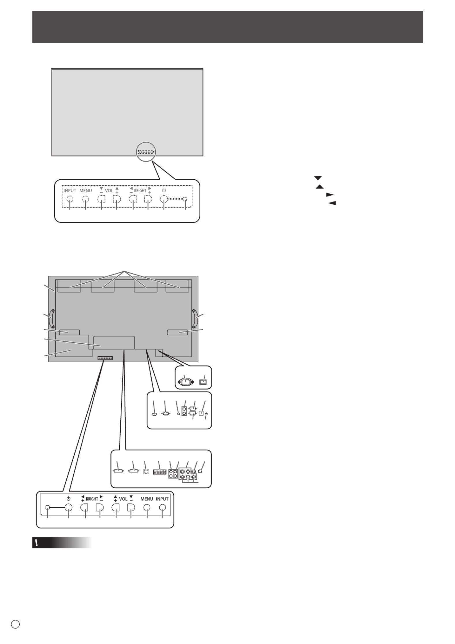
nFront view
1
2 3 4 5 6 7 8 9
The rear buttons if seen
from the front
1. LCD panel
2. INPUT button
3. MENU button
4. VOL -/Cursor control ( ) button
5. VOL +/Cursor control ( ) button
6. BRIGHT -/Cursor control ( ) button
7. BRIGHT +/Cursor control ( ) button
8. Power button
9. Power LED
Part Names
nRear view
17
15
28272625 29
21 23
16
19 2018
22 24
10
13
14
32
3130 3433
12
11
9 8 7 6 5 4 3 2
When the PN-ZB02
(optional) is attached
10
12
10
10. Fan/Fan cover
11. Vents
12. Handles
13. Expansion terminal cover
Additional input/output terminals are available by attaching
thePN-ZB02interfaceexpansionboard(optional).
14. Optional attachment section
This section is used to connect optional hardware for
function expansion. Offering this attachment location
is not a guarantee that future compatible hardware
attachments will be released.
15. AC input terminal
16. Main power switch
17. PC/AV HDMI input terminal
18. PC D-sub input terminal
19. Audio input terminal
20. Audio output terminals
21. RS-232C output terminal
22. RS-232C input terminal
23. Optional terminal
This terminal is provided for possible future (optional)
function expansion. Offering of this terminal is not a
guarantee that future expanded functionality will be
provided.
24. Control kit terminal
When the PN-ZB02 (optional) is attached
25. PC/AV DVI-D input terminal
26. PC/AV DVI-D output terminal
27. LAN terminal
28. External speaker terminals
29. Audio 1 input terminals
30. Audio 2 input terminals
31. PC RGB input terminals
32. AV component input terminals
33. AV video input terminal
34. AV S-video input terminal
Caution
• ConsultyourSHARPdealerforattachment/detachmentof
optional parts.
• Donotblockthefancover.
• Donotopentheexpansionterminalcoverbyyourself.
There are high voltage parts inside the cover which may
cause an electric shock.

11 E
Part Names
n
Remote control unit
(Supplied with the PN-ZR01 (optional))
1
2
3
4
5
6
7
12
9
10
11
8
1. Signal transmitter
2. POWER button
3. MUTE button
4. VOL +/Cursor control ( ) button
5. BRIGHT -/Cursor control ( ) button
6. DISPLAY button
7. MODE button
8. INPUT button
9. MENU button
10. BRIGHT +/Cursor control ( ) button
11. VOL -/Cursor control ( ) button
12. SIZE button
n
Remote control sensor box
(Supplied with the PN-ZR01 (optional))
1
2
3
4
1. Brightness sensor
2. Remote control sensor
3. Connection cable
4. Mounting bracket

12
E
111098 1 2 3 4 5 712
6
15
1413 1716
When the PN-ZB02 (optional)
is attached
Caution
• Besuretoturnoffthemainpowerswitchanddisconnect
the plug from the power outlet before connecting/
disconnecting cables. Also, read the manual of the
equipmenttobeconnected.
• Becarefulnottoconfusetheinputterminalwiththeoutput
terminal when connecting cables. Accidentally reversing
cables connected to the input and output terminals may
cause malfunctions and the other problems.
• Donotuseanycablethathasadamagedordeformed
terminal. Using such cables may cause malfunctions.
TIPS
• Imagesmaynotbedisplayedproperlydependingonthe
computer (video card) to be connected.
•
Ascreenwith1920x1080resolutionmaynotbedisplayed
correctlyonPCRGB.Inthiscase,checkthesettingsofyour
computer (video card) to verify that input signals conform to
specicationsofthismonitor.(Seepage57.)
• IfthereisacheckboxtodisableEDIDindisplaycontrol
panel,checkitwhenusingPCRGB.
• UsetheautomaticscreenadjustmentwhenaPCscreen
isdisplayedforthersttimeusingPCD-SUBorPCRGB,
orwhenthesettingofthePCischanged.Thescreenis
adjustedautomaticallywhenSELFADJUSTintheOPTION
menu is set to ON.
•
If the audio output from the playback device is connected
directly to speakers or other devices, the video on the monitor
may appear delayed from the audio portion.
Audio should be played through this monitor by connecting the
playback device to the monitor’s audio input, and connecting
the monitor’s audio output to the speakers or other devices.
• Theaudioinputterminalsusedineachinputmodeare
factory-setasfollows.
Input mode Audio input terminal
(Factory setting)
PCD-SUB,PCDVI-D,PCRGB
Audio input terminal
AVDVI-D Audio1inputterminal
AVCOMPONENT(BNC),
AVS-VIDEO,AVVIDEO
(BNC)
Audio2 input terminal
AVCOMPONENT(D-SUB),
AVVIDEO(D-SUB) Audio input terminal
PCHDMI,AVHDMI PC/AVHDMIinputterminal
1. PC/AV HDMI input terminal
• UseacommerciallyavailableHDMIcable(conformingto
theHDMIstandard).
• SetHDMIofINPUTSELECTontheOPTIONmenu
according to the device to be connected.
• SelecttheaudioinputterminaltobeusedinPCHDMI
orAVHDMIofAUDIOSELECTontheOPTIONmenu.
WhenHDMIisselected,connectiontotheaudioinput
terminal is unnecessary.
2. PC D-sub input terminal
• SetD-SUBofINPUTSELECTontheOPTIONmenu
according to the device to be connected.
• CommonterminalforAVCOMPONENTandAVVIDEO.
• WhenthePN-ZB02(optional)isattached,selecttheaudio
inputterminaltobeusedinPCD-SUBofAUDIOSELECT
on the OPTION menu.
• TousewithAVVIDEO(D-SUB),connectthegreen
terminal to the device’s video output.
3. Audio input terminal
• Useanaudiocablewithoutresistance.
• WhenthePN-ZB02(optional)isattached,settheaudio
inputterminalusedforeachinputmodeinAUDIO
SELECTontheOPTIONmenu.
4. Audio output terminals
• Theoutputsoundvariesdependingontheinputmode.
• Thevolumeoftheoutputsoundcanbexedbysetting
AUDIOOUTPUT(RCA)ontheOPTIONmenu.
• Itisnotpossibletocontrolthesoundoutputfromthe
audiooutputterminalswiththeAUDIOmenu.
5. RS-232C output terminal
6. RS-232C input terminal
• YoucancontrolthemonitorfromaPCbyconnectinga
commerciallyavailableRS-232straightcablebetween
theseterminalsandthePC.
•
WhenusingthePN-ZR01controlkit(optional)toperform
operation of multiple monitors with the remote control
unit, connect multiple monitors in a daisy chain using the
commerciallyavailableRS-232straightcable.(Seepage14.)
7. Control kit terminal
• ConnectstheremotecontrolsensorboxofthePN-ZR01
controlkit(optional).(Seepage14.)
n
Connection when the PN-ZB02 (optional)
is attached
ThePN-ZB02expansionboard(optional)allowstheuseof
additional connection terminals.
8. PC/AV DVI-D input terminal
• SetDVIofINPUTSELECTontheOPTIONmenu
according to the device to be connected.
• SelecttheaudioinputterminaltobeusedinPCDVI-Dor
AVDVI-DofAUDIOSELECTontheOPTIONmenu.
9. PC/AV DVI-D output terminal
• ThevideoofthePC/AVDVI-Dinputcanbeoutputtoan
external device.
• OutputtingHDCP-encryptedvideorequiresanexternal
devicewhichsupportsHDCP.
• Thisterminalallowsthedaisychainconnectionofupto5
monitors.
Connecting Peripheral Equipment

13 E
Connecting Peripheral Equipment
TIPS
• Thelengthofthesignalcablesorsurroundingenvironment
mayaffecttheimagequality.
• Thescreenmaynotdisplayproperlywhenusingterminals
otherthanPCDVI-D/AVDVI-Dfortheinputmode.Inthis
case, turn off the power to all the monitors connected in a
daisy chain and then turn the power on again.
• WhenconnectingmonitorsinadaisychainsetAUTO
INPUTCHANGEtoOFF.
• Videooutputisdisabledinthefollowingcases:
Whenthepoweristurnedoff
Whenthemonitorisininputsignalwaitingmode
10. LAN terminal
• YoucancontrolthemonitorfromaPConanetworkby
connecting a commercially available LAN cable between
this terminal and a network.
11. External speaker terminals
• Besuretouseexternalspeakerswithanimpedanceof6Ω
orgreaterandaratedinputofatleast10W.
321
Approx.
3-15/16 inch
(10 cm)
1.Attachaspeakercablecore(includedwiththePN-ZB02)to
the end of the speaker cable connected to the monitor.
2.Whilepushingthetab,insertthetipofthecable.
3. Release the tab.
TIPS
• Besuretoconnectthe+and-terminalsandtheleftand
right speakers properly.
• Avoidshortcircuitingthe+and-terminals.
12. Audio1 input terminals
13. Audio2 input terminals
• Settheaudioinputterminaltobeusedineachinput
modeinAUDIOSELECTontheOPTIONmenu.
14. PC RGB input terminals
• SetBNCofINPUTSELECTontheOPTIONmenutoPC
RGBwhenusingthePCRGBinputterminals.
• SelecttheaudioinputterminaltobeusedinPCRGBof
AUDIOSELECTontheOPTIONmenu.
15. AV component input terminals
•
SetBNCofINPUTSELECTontheOPTIONmenutoAV
COMPONENTwhenusingtheAVcomponentinputterminals.
• SelecttheaudioinputterminaltobeusedinAV
COMPONENTofAUDIOSELECTontheOPTIONmenu.
• CannotbeusedwhenD-SUBinINPUTSELECTonthe
OPTIONmenuissettoAVCOMPONENT.
16. AV video input terminal
• SelecttheaudioinputterminaltobeusedinAVVIDEOof
AUDIOSELECTontheOPTIONmenu.
• CannotbeusedwhenD-SUBinINPUTSELECTonthe
OPTIONmenuissettoAVVIDEO.
17. AV S-video input terminal
• SelecttheaudioinputterminaltobeusedinAVS-VIDEO
ofAUDIOSELECTontheOPTIONmenu.
Multiple monitor connection
The monitors can be aligned and used as a large screen.
[Example]
Second monitor
Secondary
(Expansion unit)
ID No.: 2
Third monitor
Secondary
(Expansion unit)
ID No.: 3
First monitor
Primary
(Main unit)
ID No.: 1
Fourth monitor
Secondary
(Expansion unit)
ID No.: 4
Remote control sensor box
(Supplied with the PN-ZR01 (optional))
TIPS
• ConnecttheRS-232Ccablesinorder,startingwiththerst
monitor (primary monitor). If monitors are connected in a
different order they may not be operable.
• Alwaysinstalltheremotecontrolsensorboxontheprimary
monitor.
n
Connection with video cable
May vary depending on the system being used.
IfusingthePC/AVDVI-Dterminal,upto5monitorscanbe
connectedinadaisychain.(WhenthePN-ZB02isattached)
shows the
signal flow
PC/AV DVI-D
input terminal
First monitor Second monitor
PC/AV DVI-D
output terminal
PC/AV DVI-D
input terminal
Digital signal (DVI) cables
(commercially available)
To PC digital RGB output terminal

14
E
n
Connection with RS-232 cable
IfyouconnectthemonitorinadaisychainusingRS-232
cable, using the monitor buttons on the primary (main unit),
settings are copied to the secondary (expansion unit) and
operation from the primary can perform operation for all
monitors.SettingeachIDNo.inthemonitorisrequired.
1. Connect the monitors in order.
Therstmonitorwillbesetasprimary(mainunit)andthe
second monitor and beyond will be secondaries (expansion
units).
ConnecttheRS-232Coutputterminaloftherstmonitor
(primary)andtheRS-232Cinputterminalofthesecond
monitor(secondary)togetherusingRS-232cable(straight).
Connectinthesamewaytothethirdandsubsequentmonitors.
Upto25monitorscanbeconnected.(Dependingonthelength
of the cable used and the surrounding environment.)
RS-232 straight cable
(commercially available)
First monitor: primary
Second monitor: secondary
Third monitor: connects to secondary
RS-232C input terminal
RS-232C
input terminal
RS-232C
output terminal
RS-232C
output terminal
2. Set the ID No.
Perform operation with the rear side buttons on the primary
monitor.IfyousetAUTOASSIGNIDNo.,locatedinthemenu
ofthemonitortoON,theIDNo.willbeautomaticallyassigned
in order from the primary. (See page 24.)
(IfyouattachPN-ZR01thecontrolkit(optional),youcan
perform operation of the monitors with the remote control unit.)
n
Connection with the control kit (optional)
If performing operation of the monitor with the remote control
unit,thePN-ZR01controlkit(optional)isrequired.
• Canperformoperationofanarbitrarymonitororall
monitorswiththeremotecontrolunitoftherstmonitor.
• Canperformoperationofupto25monitors.
• ConnectthemonitorstogetherinadaisychainwithRS-232
cable.
Attach the remote control sensor box as shown in the following
illustration.
* Whenattachedtotheleftside,becausethetopand
bottom for the remote control sensor box will be reversed
(the connection cable will be on top), the right side is
recommended.
Caution
• Whenattachingtheremotecontrolsensorbox,turnthe
mainpowerswitchOFF.
• Exceptfortheremotecontrolsensorboxconnectioncable,
do not insert any other cable into the control kit terminal.
Also, do not connect any connection cables that have been
extended with commercially available cables.
For the monitor in
landscape orientation
For the monitor in
portrait orientation
1. Insert the anti-rotation protrusion of the mounting
bracket into the anti-rotation hole of the monitor.
2. Secure the stand angling hole of the monitor with the
mounting screw.
3. Adjust the angle of the remote control sensor box, and
secure it with the xing screw, so that it may accurately
receive signals from the remote control unit.
Anti-rotation protrusion
Angle
adjustment
Anti-rotation hole
Mounting bracket
Mounting screw (short)
Fixing screw
Remote control
sensor box
Stand angling hole
4. Insert the remote control sensor box connection cable
into the control kit terminal.
Connection cableControl kit terminal
Remote control
sensor box
TIPS
• Whenyouconnecttheremotecontrolsensorbox,the
brightness sensor can be used.
The screen brightness will automatically change according
to lighting conditions and the surrounding brightness. (See
page25.)
• Dependingonwhereithasbeenplacedorthesurrounding
conditions, the remote control sensor box may be
affected by the brightness of the main unit screen and the
brightness sensor may respond.
• Donotinstalltheremotecontrolsensorboxinextremely
bright or dark areas. The brightness sensor may not
function properly.
Brightness
sensor
Connecting Peripheral Equipment

16
E
Binding Cables
The cables connected to the terminals on the rear of the monitor can be fastened with the cable clamps.
Insert the cable clamp into the cable clamp attachment on the rear of the monitor and fasten the cables.
: Cable clamp attachment
Cable clamp
Cable
Cable clamp
attachment
Removing the Handles
The handles can be removed.
The removed handles can be attached on the side.
1. Removethehandlescrewsandremovethehandlesand
handle spacers.
2. Pass the handle screws through the handles and handle
spacers in order and secure.
Caution
• Thehandles,handlescrewsandhandlespacersarefor
thismonitor.Donotusethemforanyotherdevices.
• Whenattachingthehandles,alwaysusethismonitor’s
handles, handle spacers, and handle screws.
• Besurethehandlesareattachedsecurely.
TIPS
• Tolowertheheightofthehandles,attachthehandleswith
the handle spacers removed. To attach the handles with
the handle spacers removed, secure the handles with the
included handle screws (short).
Handle
Handle screws
Handle spacers
Handle spacers
Afxing the Protection Covers
Afterinstallingthemonitor,afxtheprotectioncovers
(4 pieces) as necessary.
Protection cover
Protection cover

17 E
Turning Power On/Off
Caution
• TurnonthemonitorrstbeforeturningonthePCor
playback device.
• WhenswitchingthemainpowerswitchorthePOWER
buttonoffandbackon,alwayswaitforatleast5seconds.
A short interval may result in a malfunction.
Turning on the main power
Main power switch
Caution
• Themainpowermustbeturnedon/offwiththemainpower
switch.Donotconnect/disconnectthepowercordorturn
the breaker on/off while the main power switch is on.
• Foracompleteelectricaldisconnection,pulloutthemain
plug.
Turning power on/off
PressthePOWERbuttonontheremotecontrolunitorthe
monitoritselftoturnthepowerON/OFF.
Whenthemainpowerswitchisoff,themonitorcannotbe
turnedonusingthePOWERbuttonontheremotecontrolunit.
Power LED Power button
Status of a power LED Status of the monitor
Greenlighting Power on
Orange lighting Power off (Standby mode)
Greenashing Input signal waiting mode
TIPS
• Ifthemonitorisintheinputsignalstandbymodeandyou
pressthePOWERbuttonontheremotecontrolunit,the
monitor enters standby mode.
• SettingtheSCHEDULEashesthepowerLEDalternately
in red and orange in standby mode.
• Todisablethelogoscreenfromdisplayingwhenturning
thepowerON,setLOGOSCREENtoOFFontheSETUP
menu.(Seepage25.)
• IfyouchangetheremotecontrolmodetoALLMONITORS,
powercanbeturnedON/OFFforallsecondarymonitors
connectedwithRS-232cable.(Foroperationwiththe
monitor buttons, use the buttons on the primary monitor.)
nOperation mode
Whenthemonitoristurnedonforthersttimeafterbeing
shipped from the factory, the operation mode setting screen
willbedisplayed.SetittoMODE1orMODE2.
MODE1 ....OFFIFNOOPERATIONissettoON,and
STANDBYMODEissettoLOWPOWER.(These
settings can not be changed.)
If there is no operation for 4 hours or more, the
monitor automatically enters standby mode. Power
consumptioninstandbymodeisalsominimized.
MODE2 .... Willperformstandardoperation.
OFFIFNOOPERATIONissettoOFF,and
STANDBYMODEissettoSTANDARD.These
settings can be changed.
Evenafterbeingset,changescanbemadeusing
OPERATIONMODE,locatedinthemenuofthemonitor.(See
page 24.)
nDate/time setting
•
Ifthetimehasyettobesetwhenthemonitorisrstturnedon,
the date/time setting screen appears. Set the date and time.
DATE/TIME SETTING
SET
CANCEL
/ /
OK···[MENU]
: :
01 01 11/00 00:/ 20
1. Press , , or to select the date and
time, and press or to change the numerical
values.
2. Press or toselectSETandthenpress
MENU
.
• Besuretosetthedateandtime.
•
The date/time setting screen will close automatically if no
operationisperformedforabout15seconds.Thedate
andtimecanbesetusingDATE/TIMESETTINGfromthe
OPTION menu when the date/time setting screen disappears.
TIPS
• Setthedatein“Day/Month/Year”order.
• Setthetimeona24-hourbasis.
• The clock is maintained by the internal battery.
• If you already set the time but the date/time setting
screen appears when the power is turned on, the
internal battery may be exhausted. Please contact
your local Sharp servicing dealer or service center for
assistance with battery replacement.
• Estimatedservicelifeoftheinternalbattery:About5
years (depending on monitor operation)
•
The initial battery was inserted at the factory when the
monitor was shipped, so it may run out of power before
its expected operation life.
Disabling power on/off operations
Power on/power off operations can be disabled in order to protect
themonitorfromanaccidentalpoweroff.SettheADJUSTMENT
LOCKinFUNCTIONmenuto“ON2”.(Seepage31.)

E
19
5. BRIGHT +/- (Backlight adjustment)
Pressing or displaystheBRIGHTmenuwhenthe
menu screen is not displayed.
B R I G H T 15
Press or toadjustthebrightness.
* If you do not press any buttons for about 4 seconds, the
BRIGHTmenuautomaticallydisappears.
* WhenBRIGHTNESSSENSORisONorON:DISPLAY,
whenthebrightnessisadjustedBRIGHTNESSSENSOR
willbecomeOFF.
6. SIZE (Screen size selection)
The menu is displayed.
Press or toselectthescreensize.(Seepage20.)
Ifusingthemonitorbuttons,selectSIZEfromtheOPTION
menu.
7. DISPLAY
Displaysmonitorinformation.Whenyoupressthisbutton
again, the display disappears.
INPUT MODE
SIZE
COLOR MODE
BRIGHT
VOLUME
ID No.
MODEL
S/N
STATUS
REMOTE CONTROL SENSOR BOX
:
:
:
:
:
:
:
:
:
:
INFORMATION
1 9 2 0 x 1 0 8 0 V: 60 Hz H: 67.5 kHz
PC D-SUB
WIDE
STD
31
15
0
PN-V602A
XXXXXXXX
0000-0000-0000-0000
NOT CONNECTED
01/01/2016 FRI 00:00:00
WhenthePN-ZB02(optional)isattached,thedisplaychanges
fromINFORMATION1→INFORMATION2→cleardisplay,
and so on every time you press this button.
• Thedisplaydisappearsautomaticallyafterabout15
seconds.
•
LAN
is displayed during LAN communication.
• If
LAN
is displayed in red, there is a duplicate IP address.
If using the monitor buttons, press underINFORMATIONin
the OPTION menu.
8. MODE (Color mode selection)
Eachtimeyoupressthisbutton,thecolormodechangesin
the following order:
STD(Standard)→VIVID→sRGB→
HIGHILLUMINANCE→STD...
• HIGHILLUMINANCEisadisplaywithcolorssuitedto
bright locations.
• sRGBappliestoPCinputonly.
sRGBisinternationalstandardofcolorrepresentation
speciedbyIEC(InternationalElectrotechnical
Commission).Colorconversionismadeintakingaccount
ofliquidcrystal’scharacteristicsandrepresentscolortone
close to its original image.
Ifusingthemonitorbuttons,selectCOLORMODEfromthe
PICTUREmenu.
Basic Operation

E20
Basic Operation
nSwitching the screen size
Evenwhenthescreensizeischanged,thedisplaymayremainthesamedependingontheinputsignal.
WIDE PCinput Displaysimagesoitllstheentirescreen.
AVinput Animagewitha4:3aspectratioisstretchedtolltheentire
screen.
ZOOM 1 PCinput Animagewitha4:3aspectratioisenlargedtolltheentirescreen
without changing the aspect ratio. The edges of the image may be
cut off.
AVinput
ZOOM 2 PCinput UsethissizeifZOOM1cutsoffthesubtitles.
AVinput
NORMAL PCinput Displaysimagesoitllsthescreenwithoutchangingtheaspect
ratio of the input signals.
AVinput Displaystheentireimageoftheaspectratioof4:3without
changing the aspect ratio.
Dot by Dot PCinput DisplaysthedotsofthesignalsinputfromtheconnectedPCas
the corresponding dots on the screen.
AVinput Displaysthedotsoftheinputsignalsasthecorrespondingdotson
the screen.
TIPS
• Usingthismonitor’sscreen-sizeswitchingordual-screendisplayfunctionstocompressorexpandthescreenforcommercial
orpublicviewinginestablishmentslikecafesorhotelsmayinfringeontherightsofthecreators,asprotectedbyCopyright
Law, so please be careful.
• When“Enlarge”isset,thescreensizeisxedto“WIDE”mode.
• Whendual-screendisplayisselected,thescreensizecannotbechanged.
• Theappearanceoftheoriginalvideomaychangeifyouselectascreensizewithadifferentaspectratiothantheoriginal
image(e.g.TVbroadcastorvideoinputfromexternalequipment).
• Whenanordinarynon-wideimage(4:3)isviewedwiththewholescreenusingthescreen-sizeswitchingfunctionofthis
monitor, the edge of the image may be lost or appear distorted. If you wish to respect the creator’s intentions, set the screen
sizeto“NORMAL”.
• Whenplayingcommercialsoftware,partsoftheimage(likesubtitles)maybecropped.Inthiscaseselecttheoptimalscreen
sizeusingthescreen-sizeswitchingfunctionofthismonitor.Withsomesoftware,theremaybenoiseordistortionatthe
edges of the screen. This is due to the characteristics of the software, and is not a malfunction.
• Dependingontheoriginalimagesize,blackbandsmayremainattheedgesofthescreen.

21 E
Remote Control Mode
Withtheremotecontrolunitit’spossibletoperformoperation
of...
• Theprimarymonitor
• MonitorswithaspeciedIDNo.
• Allprimary/secondarymonitors
It’s necessary to specify which type of operation will be
performed in advance.
1. If using the remote control unit, press
MODE
for approx 5
seconds.
If using the monitor buttons, hold both and at
the same time on the primary.
▲
▲
THIS MONITOR ONLY
REMOTE CONTROL MODE
MODE
OK CANCEL
Operate this monitor.
2. Press or , select the mode, then perform
settings.
THIS MONITOR ONLY
Performs operation of only the primary using the remote
control unit.
[Example]Ifthevolumeislowered,thevolumeoftheprimary
will lower.
Secondary
ID No.: 2
Secondary
ID No.: 3
Primary
ID No.: 1
Secondary
ID No.: 4
VOLUME 10
Press to lower the volume
SPECIFIED MONITOR
PerformsoperationofamonitorwithaspeciedIDNo.using
the remote control unit.
Press or or to toselectIDNo.,thenpress
selecttheIDNo.ofthemonitorthatyouwilloperate.
*Whenitreceivessignalsfromtheremotecontrolunit,
“Operatingspeciedmonitor.”willbedisplayedonthe
primary screen.
[Example.]IfIDNo.issetto3andthevolumeislowered,
thevolumeofthemonitorforIDNo.:3willlower.
Secondary
ID No.: 2
Secondary
ID No.: 3
Primary
ID No.: 1
Secondary
ID No.: 4
VOLUME 10
Press to lower the volume
WhenyouwouldliketoconrmtheIDNo.thatissettothe
monitor, press or toselectIDNo.DISPLAY,then
press .TheIDNo.willbedisplayedonthescreen.
ALL MONITORS
Performs operation of all primary/secondary monitors.
*
ALL
will be displayed on the menu of the primary.
*Whenitreceivessignalsfromtheremotecontrolunit,
“Operating all monitors.” will be displayed on the secondary
screen.(Excludingpowerandinputmodeselectionoperation)
*Settingsmaynotbereecteddependingonthestateofthe
connected monitors.
[Example]IfthepowerfortheprimaryisturnedON,thepower
for all the monitors will be turned ON.
Secondary
ID No.: 2
Secondary
ID No.: 3
Primary
ID No.: 1
Secondary
ID No.: 4
Power ON Power ON
Power ONPower ON
Press to turn the power ON
POWER
Press or toselectEXPANDITEM,andpress or
to select to perform this action or not.
OFF ...........Forallmonitors,onlypower,inputmode
selection, and product information display
operationswillberecognized.
ON .............Forallmonitors,alloperationswillbe
recognized.
After returning to the normal screen with
procedure3,when5minuteshavepassedfrom
the end of operation, it will automatically return
toOFF.
AL [EXPAND ITEM]L
will be displayed on the menu of
the primary.
*
EvenwhenREMOTECONTROLMODEisset
to ALL MONITORS, certain settings such as
LANsettingsandIDNo.settingswillnotbe
reectedontheothermonitors.
3. Press or to select OK, then press
MENU
and
return to the normal screen.
4. Perform operation.
Caution
• WhentheremotecontrolmodeissettoALLMONITORS
andEXPANDITEMissettoON,performingremotecontrol
operationsthatchangeadjustmentvalueswillresultin
thesecondaryadjustmentvaluesbeingthesameasthe
primaryadjustmentvalues.
Secondary
ID No.: 2
Secondary
ID No.: 3
Primary
ID No.: 1
Secondary
ID No.: 4
Secondary
ID No.: 2
Secondary
ID No.: 3
Primary
ID No.: 1
Secondary
ID No.: 4
VOLUME 12 VOLUME 11
VOLUME 10VOLUME 9
VOLUME 10 VOLUME 10
VOLUME 10VOLUME 10
Press to lower the volume
Becarefulofthiswhenadjustingindividualdisplays.
TIPS
• Youcancopythesettingvaluesoftheprimarytoother
monitorswithCOPYSETTINGVALUE.(Seepage25.)
• Thebuttonsonthemonitoritself(primary)arealsoeffective
in remote control mode.
• Whenmonitorsconnectedinadaisychainareinstandby
modeforLOWPOWER,operationcannotbeperformedfor
subsequentmonitors.

22
E
Menu Items
Displaying the menu screen
Videoandaudioadjustmentandsettingsofvariousfunctions
are enabled. This section describes how to use the menu
items. See pages 23 to 27 for details of each menu items.
Caution
• Donotturnthemainpowerswitchoffwhilethemenuitems
arebeingdisplayed.Doingsomayinitializethesettings.
nExample of operation
(AdjustingCONTRASTinthePICTUREmenu)
1. Press
MENU
to display the menu screen.
1 3 6 6 x 7 6 8 V: 60 Hz H: 47.7 kHz
AUTO
CLOCK
PHASE
H-POS
V-POS
H-SIZE
V-SIZE
H-RESOLUTION
V-RESOLUTION
RESET
SCREEN
PICTURE
AUDIO
SETUP
OPTION
MU ILT
PIP/PbyP
600
25
610
37
50
50
1366
768
SCREEN 1/1
END···[MENU]
PC D-SUB
2. Press or to select PICTURE, and press .
3. Press or to select CONTRAST.
AUTO
ANALOG GAIN
ANALOG OFFSET
BRIGHT
CONTRAST
BLACK LEVEL
TINT
COLORS
SHARPNESS
RGB INPUT RANGE
64
86
31
30
30
30
30
12
1/2
FULL
PC D-SUB
PICTURE
SCREEN
PICTURE
AUDIO
SETUP
OPTION
MU ILT
PIP/PbyP
OK···[MENU]MOVE OSD···[DISPL ]AY
1 3 6 6 x 7 6 8 V: 60 Hz H: 47.7 kHz
4. Press or to adjust the setting.
AUTO
ANALOG GAIN
ANALOG OFFSET
BRIGHT
CONTRAST
BLACK LEVEL
TINT
COLORS
SHARPNESS
RGB INPUT RANGE
64
86
31
40
30
30
30
12
1/2
FULL
PC D-SUB
PICTURESCREEN
PICTURE
AUDIO
SETUP
OPTION
MU ILT
PIP/PbyP
OK···[MENU]MOVE OSD···[DISPL ]AY
1 3 6 6 x 7 6 8 V: 60 Hz H: 47.7 kHz
Foritemsthathave , press , make settings and then
press
MENU
.
5. Press
MENU
twice to close the menu screen.
TIPS
• Themenuwilldifferdependingontheinputmode.
• Themenuscreenwillcloseautomaticallyifnooperationis
performedforabout15seconds.(DATE/TIMESETTING,
SCHEDULEandLANSETUPscreenswillcloseinabout4
minutes.)
nMenu screen display
AUTO
ANALOG GAIN
ANALOG OFFSET
BRIGHT
CONTRAST
BLACK LEVEL
TINT
COLORS
SHARPNESS
RGB INPUT RANGE
64
86
31
30
30
30
30
12
1/2
FULL
PC D-SUB
SCREEN
PICTURE
AUDIO
SETUP
OPTION
MU ILT
PIP/PbyP
PICTURE
OK···[MENU]MOVE OSD···[DISPL ]AY
1 3 6 6 x 7 6 8 V: 60 Hz H: 47.7 kHz
1 3 2
4
1 Nameofthemenu
2 Input mode
3 An item being selected (highlighted)
4 Screen resolution of input signal, and other data.
TIPS
• Itemsthatcannotbeselectedappearingray.
(e.g.Functionnotsupportedbythecurrentinputsignal)
nMenu Items
The displayed menu items vary depending on whether or not
thePN-ZB02(optional)isattached.
ThefollowingmenuswillbedisplayedonlywhenthePN-ZB02
(optional) is attached.
Menu Item
SETUP HOTPLUGCONTROL DVI
RS-232C/LANSELECT
LANSETUP
OPTION INPUTSELECT DVI
BNC
AUDIOSELECT PCDVI-D
PCD-SUB
PCRGB
AVDVI-D
AVCOMPONENT
(BNC)
AVCOMPONENT
(D-SUB)
AVS-VIDEO
AVVIDEO(BNC)
AVVIDEO(D-SUB)
PIP/PbyP PIPSOURCE
E
23
Menu item details
The menu will differ depending on the input mode.
nSCREEN
You can move the menu screen display position each time
DISPLA
Y
is pressed.
AUTO (PC D-SUB/PC RGB)
TheCLOCK,PHASE,H-POS,andV-POSareautomatically
adjusted.
Pressing performsadjustment.
UsethisautomaticadjustmentwhenyouusethePCD-sub
inputterminalorPCRGBinputterminalstodisplayaPC
screenforthersttimeorwhenyouchangethesettingof
thePC.(Seepage30.)
CLOCK (PC D-SUB/PC RGB)
Adjustsfrequencyforsamplingclockforapplicablevideo.
Adjustwhenthereisickeringintheformofverticalstripes.
Whenusingtheadjustmentpattern(seepage30),make
adjustmentssothatnoverticalstripenoiseappearsinit.
PHASE (PC D-SUB/PC RGB)
Adjustssamplingclockphaseforapplicablevideo.
Useful when small characters appear with low contrast and/
orthereareickersatcorners.
Whenusingtheadjustmentpattern(seepage30),make
adjustmentssothatnohorizontalstripenoiseappearsinit.
* AdjustmentstoPHASEshouldbemadeonlyafterCLOCK
has been correctly set.
H-POS
Adjustthehorizontalpositionoftheimage.
V-POS
Adjusttheverticalpositionoftheimage.
H-SIZE
Adjustthehorizontalsizeoftheimage.
V-SIZE
Adjusttheverticalsizeoftheimage.
H-RESOLUTION (PC D-SUB/PC RGB)
Setsproperhorizontalresolutionwhentheresolutionof
inputsignalsisnotrecognizedproperly.(Adjustmentmaybe
impossible with some signals.)
V-RESOLUTION (PC D-SUB/PC RGB)
Sets proper vertical resolution when the resolution of input
signalsisnotrecognizedproperly.(Adjustmentmaybe
impossible with some signals.)
RESET
ResetsthevaluesoftheSCREENmenuitemstothefactory
preset values.
Select ON and then press
MENU
.
n
PICTURE
You can move the menu screen display position each time
DISPLA
Y
is pressed.
AUTO (PC D-SUB/PC RGB)
TheANALOGGAINandANALOGOFFSETare
automaticallyadjusted.
Pressing performsadjustment.
ANALOG GAIN (PC D-SUB/PC RGB)
Adjuststhebrightportionsofthevideoinputsignal.
ANALOG OFFSET (PC D-SUB/PC RGB)
Adjuststhedarkportionsofthevideoinputsignal.
BRIGHT
Adjuststhebacklightbrightness.(InPIPmode,themainside
settingisreectedintheimage.)
CONTRAST
Adjuststhedifferencebetweenthebrightanddarkportions
of the image.
BLACK LEVEL
Adjuststheentirebrightnessofthevideosignals.
TINT
Adjuststhehue.Selecting+changesthecolortowards
green,andselecting-changesittowardsmagenta.
COLORS
Adjuststhecolorintensity.
SHARPNESS
Adjuststhesharpnessoftheimage.
RGB INPUT RANGE (PC DVI-D/PC HDMI/PC D-SUB/PC
RGB/AV DVI-D/AV HDMI)
SetstheRGBinputsignalrange.WhenusingHDMIsetto
AUTO,theRGBinputsignalisdetectedautomatically.Use
AUTO normally.
IftheRGBinputsignalrangecannotbesetappropriately
evenwhenusingAUTO,setaccordingtotheimage.When
the setting is different, images will be displayed with washed
out blacks and compressed gradients.
ADVANCED (AV input)
Youcanadjustmorespecically.(Seepage30.)
COLOR MODE
Changesthecolormodeonthescreen.Thecolormodeon
the screen can also be changed using a remote control unit.
(Seepage19.)
* sRGBisPCinputonly.Seepage19fordetails.
WHITE BALANCE
THRU .............. Displaystheinputsignallevelasis.(forPC
DVI-D/PCHDMIonly)
PRESET ......... SelectsthecolortemperatureusingPRESET.
USER .............. UsedforadjustingR-/G-/B-CONTRASTand
R-/G-/B-OFFSETrespectively.
PRESET
SelectsthecolortemperaturewhentheWHITEBALANCEis
settoPRESET.
The setting values are shown for reference. The color
temperature of the screen varies over time.
This function is not intended to keep the color temperature
constant.
Menu Items

E24
USER
AdjustseachitemwhentheWHITEBALANCEissetto
USER.
R-CONTRAST ....Adjustsbright-tonedredcomponent.
G-CONTRAST ....Adjustsbright-tonedgreencomponent.
B-CONTRAST ....Adjustsbright-tonedbluecomponent.
R-OFFSET ..........Adjustsdark-tonedredcomponent.
G-OFFSET .........Adjustsdark-tonedgreencomponent.
B-OFFSET ..........Adjustsdark-tonedbluecomponent.
COPY TO USER
CopiesthevaluesetforPRESETtotheUSERsetting.
Select ON and then press
MENU
.
GAMMA
Selectsthegamma.USERsetsthegammatothesent
value (see page 36). (In PIP mode, the main side setting is
reectedintheimage.)
WhenusingLOCALDIMMING,itcontrolsthebrightnessper
area. So, the gamma may differ from the set value.
LOCAL DIMMING
Automatically controls the backlight brightness per area
according to the image. Increasing the level of this setting
will result in higher contrast of the image, and will lower the
monitor power consumption.
Lightleakageand/oraring-likeappearancemaybeseen
dependingontheimage.Changethesettinginthissituation.
(InPIPmode,themainsidesettingisreectedintheimage.)
Whenusingmultiplemonitors,ifthereisadifferenceinthe
brightnessbetweenthemonitors,adjustthesetting.
POWER LIMITED
CanbesetwhenLOCALDIMMINGisHIGH.Setthevalue
so that it is smaller than the set power consumption (see
page56.)byadjustingthebrightness,etc.
DISPLAY COLOR PATTERN
Displaysacolorpattern.Canbedisplayedwhilethemenu
screen is displayed, so you can refer to the pattern while
adjustingtheimage.
OFF ....................No pattern display.
WHITE ................Whitesinglecolorpatterndisplay.
RED ....................Red single color pattern display.
GREEN ...............Greensinglecolorpatterndisplay.
BLUE ..................Bluesinglecolorpatterndisplay.
USER.................. Red/green/blue mixed color pattern display.
WhenUSERisselected,seteachcolor’s
level.
RESET
ResetsthevaluesofthePICTUREmenuitemstothefactory
preset values.
Select ON and then press
MENU
.
nAUDIO
TREBLE
Adjuststhevolumeoftreble-levelsound.
BASS
Adjuststhevolumeofbass-levelsound.
BALANCE
Adjuststhebalanceoftheaudiosoundbetweenrightand
left.
RESET
ResetsthevaluesoftheAUDIOmenuitemstothefactory
preset values.
Select ON and then press
MENU
.
nSETUP
OSD H-POSITION
Adjuststhehorizontaldisplaypositionofmenuscreen.
OSD V-POSITION
Adjuststheverticaldisplaypositionofmenuscreen.
MONITOR
Select the installation direction of the monitor.
LANDSCAPE ............Landscape orientation
PORTRAIT ...............Portrait orientation
LANGUAGE
Sets the display language for the menu screen.
POWER ON DELAY
You can delay the screen display after the monitor is turned
on.Theperiodcanbesetupto60secondsinunitsofone
second.Whenthisfunctionisactivated,thepowerLED
ashes(atapprox.1secondinterval)inorange.Thisfunction
isdisabledwhen0isspecied.
OPERATION MODE
MODE1 ......OFFIFNOOPERATIONissettoON,and
STANDBYMODEissettoLOWPOWER.
(These settings can not be changed.)
MODE2 ...... Willperformstandardoperation.
OFFIFNOOPERATIONissettoOFF,and
STANDBYMODEissettoSTANDARD.These
settings can be changed.
STANDBY MODE
WhenSTANDARDisselected,startuptimefromstandby
mode is reduced. Note, however that, more power will be
consumed in standby mode.
WhenLOWPOWERisselected,currentconsumption
is reduced while the monitor is in standby mode. Note,
however, that the startup time from standby mode becomes
longer.
IfsettoLOWPOWER,certainRS-232Ccommandscannot
be used in standby mode, and control via LAN will be
disabled.
OFF IF NO OPERATION
Determineswhetherornottosetthemonitortogointo
standby mode when there is no operation from the remote
controlunit,RS-232Ccommands,orLANforover4hours.
HOT PLUG CONTROL
SetswhethertousehotplugcontrolforthePC/AVHDMI
andPC/AVDVI-Dinputterminals.
RS-232C/LAN SELECT
Selects the method with which to control the monitor from
the computer.
ID No. SET
AssignsIDnumberstomonitorsconnectedinadaisychain
(seepage34),usingtheremotecontrolunitorRS-232
cables.
Thenumbers1to255areavailableforIDnumbers.
If“0”isset,thesystemregardsthisasthestatewherenoID
number is set.
AUTO ASSIGN ID No.
IDNo.tobeusedwillbeautomaticallyassignedwhen
multiplemonitorsareconnectedwithRS-232C.
Select ON, then press
MENU
. Perform operations with the
primary monitor.
Menu Items

E
25
Menu Items
COPY SETTING VALUE
Whenthemonitorhasbeenconnectedtomultiplemonitors
withRS-232C,youcancopytheprimarysettingdetailsto
the secondary. Perform operations with the primary monitor.
SelectsthesettingstocopywithCOPYSETTINGVALUE
TARGET.
“PICTURE”ONLY
... CopiesthePICTUREmenusettings.*
ALL ........................ e settings.*Copiesallth
SelecttheIDNo.ofthemonitorthatyouwouldlikecopyto
withCOPYTOIDNo.,thenselectCOPYandpress
MENU
.
If you select ALL, settings will be copied to all monitors.
WhenyouwouldliketoconrmtheIDNo.thatissettothe
monitor,selectIDNo.andpress .TheIDNo.willbe
displayed on the screen.
*CertainsettingdetailssuchasANALOGGAIN,ANALOG
OFFSET,andDISPLAYCOLORPATTERNcannotbe
copied.
LOGO SCREEN
Sets whether or not to display the logo screen.
BAUD RATE
SelectsthecommunicationspeedusedforRS-232C
communication.
LAN SETUP
Conguresthesettingstocontrolthemonitorfromthe
computerviaLAN.(Seepage45.)
AUTO ASSIGN FIXED IP ADDR.
CanbeenabledwhenRS-232C/LANSELECTisLANand
theDHCPCLIENTisOFF.
SettheDHCPCLIENTforsecondarymonitorsconnected
byRS-232CtoOFFandaxedIPaddressisautomatically
allocated.
If the IP address is a duplicate with a network device other
than a monitor, individually change the IP address.
OPTION DC OUT SETTING
Normally,leavethissettingasOFF.
Whenusinganoptionalpart,ifinstructionappears,change
the setting accordingly.
HDMI AUTO VIEW
WhenONisselected,thescreensizeisadjusted
automaticallyaccordingtothescreensizecontrolsignal
includedinthevideosignalinputfromtheAVHDMIinput
terminal.
BRIGHTNESS SENSOR
(When connected to the PN-ZR01 (optional) only)
WhensettoONorON:DISPLAY,thebrightnesswill
automatically change according to the lighting and
surrounding brightness. Performs operation with the primary
monitor.IfsettoON:DISPLAY,theeffectwillbedisplayed
with a .
If connecting to multiple monitors, the brightness of all the
monitors will change.
The will be displayed on the primary only.
WhensettingBRIGHTinSCHEDULEontheOPTIONmenu,
setBRIGHTNESSSENSORtoOFF.
BRIGHTNESS SENSOR SETTING
(When connected to the PN-ZR01 (optional) only)
Performsadjustmentstothebrightnesssensor.Performs
operation with the primary monitor.
Set the surrounding brightness and the current screen
luminancetoAMBIENTBRIGHTNESSandSCREEN
BRIGHTNESS.
IndividuallysetWHENLIGHT:andWHENDARK:.
EvenifbrighterordarkerthanthesetAMBIENT
BRIGHTNESS,thescreenbrightnesswillnotchange.
CURRENTAMBIENTBRIGHTNESSisshownforreference.
E26
Menu Items
nOPTION
DATE/TIME SETTING
Set the date and time. Press or to select the date
and time, and press or to change the numerical
values.
Setthedatein“Day/Month/Year”order.
Setthetimeona24-hourbasis.(Factorydefault)
DATE/TIME FORMAT
Sets the date/time display format.
DATE ..................MM/DD/YYYY
DD/MM/YYYY
YYYY/MM/DD
(YYYY:Year,MM:Month,DD:Day)
TIME ...................Select12-or24-hourtime.
SCHEDULE (See page 29.)
You can turn the power on/off and change the screen
brightnessataspeciedtime.
INPUT SELECT
SelecttheinputmodetobeusedinPCD-Subinputterminal,
PC/AVDVI-Dinputterminal,PC/AVHDMIinputterminaland
PCRGB/AVcomponentinputterminals.
ForD-SUB,selectSETafterselectingtheinputmode,and
then press
MENU
.
D-SUBandBNCcannotbesettoAVCOMPONENTatthe
same time.
IfD-SUBissettoAVVIDEO,theAVVIDEOinputterminal
cannotbeusedforBNC.
AUDIO SELECT
Selects the terminal used to input audio signals in each input
mode.
INPUT SIGNAL (PC D-SUB/PC RGB)
IfacomputerconnectedtothePCD-sub/PCRGBinput
terminal outputs any of the following resolutions, make a
selection from the following options.
480LINES .......... AUTO, 640x480or848x480
768LINES ..........AUTO,1024x768,1280x768,1360x768or
1366x768
1050LINES ........1400x1050or1680x1050
ZOOM2SPECIALSETTING(Seepage29.)
SCAN MODE (AV input)
SetsthescanmodeusedforAVmodeinput.
MODE1 ...............Over-scan display
MODE2 ...............Under-scandisplay
MODE3 ...............Under-scandisplaywhentheinputsignal
is1080i/p.Otherwise,over-scandisplay
* EvenwhenMODE1isselected,under-scandisplayisused
whentheinputsignalis1080i/pandthescreensizeisDot
byDot.
POWER MANAGEMENT
POWERMANAGEMENTdetermineswhetherornotto
switch modes from no signal to the input signal standby
mode.
COLOR SYSTEM (AV S-VIDEO/AV VIDEO)
SelectthecolorsystemoftheAVequipmentwhichis
connectedtoAVS-videoandAVvideoinputterminal.(AUTO/
PAL/PAL-60/SECAM/NTSC3.58/NTSC4.43)
WhenAUTOisselected,thecolorsystemisautomaticallyset
according to the input signal.
AUDIO OUTPUT(RCA)
Sets the volume of sound output from the audio output
terminals.WhensettoVARIABLE2,audioisnotoutputfrom
the external speaker terminals.
VARIABLE .......... You canadjustthevolumeusingVOLUME.
FIXED ................. Disablesvolumeadjustmentandxesthe
sounds.
WhenthePN-ZB02(optional)isattached:
VARIABLE1 ........ YoucanadjustthevolumeusingVOLUME.
VARIABLE2 ........ YoucanadjustthevolumeusingVOLUME,
but audio is not output from the external
speaker terminals.
FIXED ................. Disablesvolumeadjustmentandxesthe
sounds.
AUDIO LEVEL(STEREO MINI)
Selects the maximum audio input level of the audio input
terminal.
SELF ADJUST
OnaPCD-SUB/PCRGBscreen,specifywhetherto
performscreenadjustmentautomaticallyornot.WhenON
isselected,thescreenisautomaticallyadjustedwhenits
resolutionis800x600orhigherandthetimingofinput
signalschanges.“ADJUSTING”appearsonthescreen
duringtheadjustment.Forimageswithblackedges,etc.,
dependingonthesignal,adjustmentmaynotbepossible.
InthiscaseselectOFF.(Performmanualadjustmentofthe
screen.)
AUTO INPUT CHANGE
Specifywhethertochangeinputsautomatically.WhenONis
selected and no signal is present in the selected input mode,
AUTOINPUTCHANGEautomaticallychangestheselected
mode to another mode where a video signal is present.
Whenvideosignalsexistinmultipleinputmodes,the
switching priority is as follows:
PCD-SUB,PCHDMI,AVHDMI,AVCOMPONENTandAV
VIDEO
WhenthePN-ZB02(optional)isattached:
PCDVI-D,PCHDMI,PCD-SUB,PCRGB,AVDVI-D,AV
HDMI,AVCOMPONENT,AVS-VIDEOandAVVIDEO
(Inputmodeswitchingmaytake15secondsormore,
dependingontheconnectedequipment.Inputsignals
may not be detected properly and a priority may change,
dependingontheconnectedequipmentorvideosignals.)
FAN SPEED
Sets the rotation speed of the fan.
As this number increases, the rotation speed becomes
faster.WhensettoAUTO,therotationspeedofthefanwill
change depending on the internal temperature.
SIZE
Selectsscreensize.(Seepage20.)
MUTE AUDIO
Cantemporarilyturnoffthevolume.
INFORMATION
If you press , monitor information can be checked.

E
27
Menu Items
nMULTI
ENLARGE (See page 28.)
Sets whether or not to use the enlarge function.
ADVANCED (ENLARGE)
ENLARGEH/ENLARGEV
......... Sets the number of screen splits (number of
monitors)inthehorizontal/verticaldirectionusedfor
the enlargement.
ENLARGE-POS
......... Specify the split screen to be displayed when the
enlargement function is used.
H-POS/V-POS
......... Adjustthehorizontal/verticalpositionoftheenlarged
screen.
BEZEL ADJUST
Sets whether or not to use the frame correction function.
ADVANCED (BEZEL ADJUST)
BEZELADJUST(TOP)/BEZELADJUST(BOTTOM)/
BEZELADJUST(RIGHT)/BEZELADJUST(LEFT)
......... Adjustssothatthetop/bottom/left/rightconnecting
jointsofgroupedunitswillbedisplayedsmoothly
when a group of monitors are aligned in multiples to
display a single image.
BEZEL(TOP)/BEZEL(BOTTOM)/BEZEL(RIGHT)/
BEZEL(LEFT)
......... Sets the frame width of the display.
nPIP/PbyP
PIP MODES
Sets the display method.
OFF .........Displaysonescreen.
PIP ...........Displaysasubscreeninsideamainscreen.
PbyP ........Displaysamainscreenandasubscreeninaline.
PbyP2 ......
Displaysamainscreenwhichmeasures1024pixels
in the longest direction and a sub screen in a line.
PIP SIZE
SetsthesizeofthesubscreeninPIPmode.
PIP H-POS
AdjuststhehorizontalpositionofthesubscreeninPIP
mode.
PIP V-POS
AdjuststheverticalpositionofthesubscreeninPIPmode.
PIP BLEND
In PIP mode, use this menu item to display the sub screen
transparently.
PIP SOURCE
Selects the input signal of the sub screen in PIP, PbyP, or
PbyP2 mode.
SOUND CHANGE
Sets the sound which is output in PIP, PbyP, or PbyP2 mode.
If the main screen is displayed as a full screen by the AUTO
OFFfunction,thesoundforthemainscreenisoutputeven
whenthesoundforthesubscreenisspecied.
MAIN POS
Sets the position of the main screen in PbyP or PbyP2 mode.
PbyP2 POS
Sets the position of the sub screen in PbyP2 mode.
AUTO OFF
Sets the display method when no signals for the sub screen
are input in PIP, PbyP, or PbyP2 mode.
MANUAL .......
Displaysamainscreenandablacksubscreen.
AUTO ............ Displaysthemainscreenasafullscreen.
TIPS
• WhenWHITEBALANCEissettoTHRU,BLACKLEVEL,
CONTRAST,TINT,COLORS,RGBINPUTRANGE,
GAMMA,andCOPYTOUSERcannotbeset.
• IfCOLORMODEissettosRGB,thefollowingitemscannot
be set.
WHITEBALANCE,PRESET,USER,COPYTOUSER,and
GAMMA
• WhentheCOLORMODEissettoVIVIDorHIGH
ILLUMINANCE,GAMMAcannotbeadjusted.
• STANDBYMODEcannotbesettoLOWPOWERwhen
SCHEDULEiseffectiveorwhenOFFisselectedforLEDin
FUNCTION.
• Whendisplayingthecolorpattern,itispossibletoadjust
certainitemsofthePICTUREmenu.
Non-adjustableitemscannotbeselected.
AudioinputfromtheHDMIinputterminalisalsonotoutput.

E28
nDual screen display
YoucandisplaythescreensofthePCinputsignalandAV
input signal simultaneously.
Setthisfunctionwith“PIPMODES”inthePIP/PbyPmenu.
PIP
Main screen
Sub
screen
A sub screen is displayed
inside a main screen.
PbyP
Main
screen
Sub
screen
A main screen and a sub
screen are displayed in a
line.
PbyP2
Main screen Sub
screen
Displaysamainscreen
whichmeasures1024
pixels in the longest
direction and a sub
screen in a line.
* The currently selected input signal is displayed on the main
screen.
* You cannot simultaneously display the screens of signals
ofthesametype,suchastwotypesofPCinputsignalsor
twotypesofAVinputsignals.
* The dual screen display cannot be used with the
combinationofPCDVI-DandAVHDMIorofAVDVI-Dand
PCHDMI.
TIPS
• Youmightinfringeonacopyrightoftheauthorwhichis
protected by copyright law when you display the images of
thecomputerscreenandtelevision/VCRsimultaneouslyfor
prot-makingortoshowtheimagetothepublic.
• Thescreensizefordual-screendisplayisthesameas
thescreensizeforsingle-screendisplay.TheDotbyDot
screenisdisplayedinNORMALsizeexceptwhenitisset
as the PIP main screen.
• Whendual-screendisplayisselected,theAUTOINPUT
CHANGEfunctionisdisabled.
• Whendual-screendisplayisselected,thescreencannot
be enlarged.
• Whendual-screendisplayisselected,theINPUTSELECT
options cannot be set.
• Whenaninterlacedsignal(1080i,480i,video,S-Video)is
inputtothesubscreen,horizontallinesmayicker.Ifthis
happens, display the image on the main screen.
Menu Items
nEnlarge
• Youcanalignseveralmonitorsandintegratethemintoa
single large screen to display.
• Uptovemonitorscanbealignedinboththehorizontal
and vertical directions.
• Eachmonitordisplaysenlargedviewsofseparatedimages.
(Example)
Horizontal direction: 2 monitors
Vertical direction: 2 monitors
Horizontal direction: 3 monitors
Vertical direction: 2 monitors
Setting procedure
Set using the MULTI menu.
1. Set ENLARGE to ON.
2. Select ADVANCED (ENLARGE).
3. Set the number of monitors aligned in the horizontal
direction in ENLARGE H.
4. Set the number of monitors aligned in the vertical
direction in ENLARGE V.
5. Set the section of the separated image to be displayed
on each monitor in ENLARGE-POS.
1) Press .
2) Press , , to select position, then or
press
MENU
.
TIPS
• WhenEnlargeisused,theAUTOINPUTCHANGEfunction
is disabled.
• WhenEnlargeisused,theHDMIAUTOVIEWfunctionis
disabled.

E
29
nZOOM2 SPECIAL SETTING
If you connect a laptop computer with any of the following
screen resolutions and black bands appear around the
screen,setZOOM2SPECIALSETTINGofINPUTSIGNALon
theOPTIONmenutoONandthenselectZOOM2intheSIZE
setting.
This displays the area inside the black band.
Laptop computer
resolution
Correspondingsignal*1
1280x800 1280x1024,1280x960,1400x1050*
2
1280x600 1280x720
1024x600 1024x768
*1:Thissettingiseffectiveonlywhenthescreenresolution,
including the black band, is one of the resolutions listed
above.
*2:Usetheautomaticscreenadjustment.
nSCHEDULE
You can set the time to switch the monitor on and off.
Setthisfunctionwith“SCHEDULE”intheOPTIONmenu.(See
page 26.)
WhenBRIGHTisset,setBRIGHTNESSSENSORtoOFFon
theSETUPmenu.
-
:
– – – – – – – – – –– – – – –
SCHEDULE
No.
POWER DAY OF THE WEEK
TIME INPUT BRIGHT
– –
/
– –
/
– – – – – – –
– –
:
– –
:
– –
PC D-SUB
(1)
–
-
:
– – – – – – – – – –– – – – ––
-
:
– – – – – – – – – –– – – – ––
-
:
– – – – – – – – – –– – – – ––
-
:
– – – – – – – – – –– – – – ––
-
:
– – – – – – – – – –– – – – ––
-
:
– – – – – – – – – –– – – – ––
-
:
– – – – – – – – – –– – – – ––
(5)(2) (3) (4) (6)
OK···[MENU]
1 3 6 6 x 7 6 8 V: 60 Hz H: 47.7 kHz
1. Press or to select the SCHEDULE number, and
press .
2. Set the SCHEDULE. (See the description below.)
Press or to select items, and press or to
change the setting.
3. Press
MENU
.
SCHEDULEbecomeseffective.
(1)
●:SCHEDULEeffective
-
:SCHEDULEnoteffective
(2) POWER
ON :Switchesthemonitoronatthespeciedtime.
OFF:Switchesthemonitoroffatthespeciedtimeandputs
the monitor in standby mode.
(3) DAY OF THE WEEK
SpeciesthedayoftheweektoexecutetheSCHEDULE.
0: ONLYONCE
ExecutestheSCHEDULEonceonthespeciedday.
SpecifythedayoftheweektoexecutetheSCHEDULE.
1: EVERYWEEK
ExecutestheSCHEDULEonthespecieddayofthe
week every week. Specify the day of the week to execute
theSCHEDULE.
Periodicsettingsuchas“MondaythroughFriday”isalso
possible.
2: EVERYDAY
ExecutestheSCHEDULEeverydayregardlessoftheday
of the week.
(4) TIME
SpeciesthetimetoexecutetheSCHEDULE.
Setthetimeona24-hourbasis.(Factorydefault)
Canbeenteredas12-hourtimeusingtheTIMEsettingin
DATE/TIMEFORMAT.
(5) INPUT
Speciestheinputmodeatpower-on.Whennotspecifying,
thescreenatthepreviouspower-offappears.
InputmodesdisplayedonDVI,HDMI,BNCandD-SUB
dependonINPUTSELECTsettings.
(6) BRIGHT
Sets the brightness when changing the screen brightness at
aspeciedtime.
Caution
• Donotswitchoffthemainpoweraftersettingthe
SCHEDULE.
• Specifythecorrectdateandtime.(Seepage26.)
SCHEDULEdoesnotfunctionunlessthedateandtimeare
specied.
• Checkregularlythatthesetdateandtimearecorrect.
• WhenSTANDBYMODEisLOWPOWER,SCHEDULE
cannot be set.
• Whenatemperatureabnormalityoccursandthebacklight
brightness is reduced, the brightness is not changed even
ifaschedulesettoBRIGHTisexecuted.
TIPS
• Upto8SCHEDULEitemscanberegistered.
• SettingtheSCHEDULEashesthepowerLEDalternately
in red and orange in standby mode.
• ASCHEDULEthathasalargenumberhasprecedence
over that of a small number when schedules overlap.
• IfD-SUBofINPUTSELECTontheOPTIONmenuissetto
AVVIDEO,theinputmodewillswitchtoAVVIDEO(D-SUB)
regardlessifsettoD-SUBorVIDEO.
Menu Items

E30
n
ADVANCED items (AV input) (See page 23
for additional Menu item details.)
FLESH TONE
Adjustthehuecontrol.
3D-NR
Reduce the noise of playback images on video.
Settingahigherlevelreducesmorenoise.However,itmay
cause blurring on an image.
MPEG-NR
Reduce block noise caused by digital compression.
3D-Y/C (AV VIDEO)
Specifywhethertoperform3-dimensionY/Cseparation.
Ifdotinterferenceorcross-colorisoccurringinfast-motion
scenes,selectingOFFmayimprovetheimagequality.
C.M.S.-HUE
Adjustscolortonewith6colorsofR(red),Y(yellow),G
(green),C(cyan),B(blue),andM(magenta).
C.M.S.-SATURATION
Adjustscolorvividnesswith6colorsofR(red),Y(yellow),G
(green),C(cyan),B(blue),andM(magenta).
C.M.S.-VALUE
Adjustscolorbrightnesswith6colorsofR(red),Y(yellow),
G(green),C(cyan),B(blue),andM(magenta).
TIPS
• WhenFLESHTONEissettoLOWorHIGH,C.M.S.-HUE/
-SATURATION/-VALUEcannotbeset.
Adjustments for PC screen display
nAutomatic adjustment
WhenyouusethePCD-subinputterminalorPCRGBinput
terminalstodisplayaPCscreenforthersttime,orwhen
youchangethesettingofthePC,usetheautomaticscreen
adjustment.
1. Switch the input to PC D-SUB or to PC RGB and display
the adjustment pattern. (See the description below.)
2. Press
MENU
and use or to display the SCREEN
menu.
3. Press and select “AUTO”.
4. Press .
Theautomaticadjustmentiscompleteinseveralseconds.
5. Press
MENU
twice to close the menu screen.
TIPS
• Ifthescreencannotbeadjustedproperlywithone
automaticadjustment,repeattheautomaticadjustmenttwo
orthreetimes.Trymanualadjustmentifnecessary.
nScreen display for adjustment
BeforemakingadjustmentsintheSCREENmenuor
PICTUREmenu,displayanimagetobrightentheentire
screen.IfyouareusingaWindowsPC,usetheadjustment
patternonthesuppliedCD-ROM.
Opening the adjustment pattern
ThefollowingexampleisperformedinWindows7.
1. Load the supplied CD-ROM into the computer’s CD-
ROM drive.
2. Open [CD Drive] in [Computer].
InWindowsXP,open[CDDrive]in[MyComputer].
3. Double-click [Adj_uty.exe].
Theadjustmentpatternwillappear.
Adjustthescreenautomaticallyormanually.
4. When adjustment is nished, press the [Esc] on the
computer’s keyboard to quit the adjustment program.
5. Eject the CD-ROM from the CD-ROM drive.
TIPS
• Ifthedisplaymodeonthecomputeryouareusingis
65,000colors,thecolorlevelsinthecolorpatternmay
appear differently or grayscale may appear to be colored.
(Thisisduetothespecicationsoftheinputsignalandis
not a malfunction.)
Menu Items

31 E
Youcanreturnthesettingstotheirfactory-presetvaluesand
restrict operations.
1. If using the remote control unit, press
SIZE
until “F”
is displayed in the upper left area of the screen, then
while “F” is being displayed, press , , , and
in that order.
If using the monitor buttons, press and at the
same time until “F” is displayed in the upper left area
of the screen, then while “F” is being displayed, press
and at the same time.
OFF
UNLOCKED
ON1
ON
LED
OFF
MONI RTO
FUNCTION 1/1
AL RESETL
ADJUSTMENT LOCK
ADJUSTMENT LOCK RGETTA
RS-232C
OSD DISPLAY
LED
TEMPER URE ALERTAT
STATUS ALERT
POWER BUTTON
CONTROLLER INPUT
END…[MENU]
2. Select and set the items.
ALL RESET
Resets the settings to the factory default settings.
Press ,selectALLRESET,andthenpress
MENU
.
Afterinitialization,turnthemainpowerswitchoffand
then back on.
WhenthePN-ZB02(optional)isattached,press ,
select the resetting method, and then press
MENU
.
ALLRESET1 ....Resets all the settings to the factory
default settings.
ALLRESET2 ....Returns all settings to the factory default
settings except for the following items:
LANSETUP,RS-232C/LANSELECT,
IDNo.SET,BAUDRATE,NETWORK,
MAIL,SERVICE&SUPPORT,and
SNMP(Seepages24,25,andpages49
to52.)
ADJUSTMENT LOCK
You can disable operations on the monitor and the
remote control unit that use buttons.
OFF ...Enablesoperation.
ON1 ..Disablesalloperationsotherthanturningpower
on/off,FUNCTION,andREMOTECONTROL
MODE.
ON 2 ..OnlytheFUNCTIONandREMOTECONTROL
MODEoperationsareenabled.
DisablesalloperationsotherthanFUNCTION
andREMOTECONTROLMODE(notevenpower
on/off).
ADJUSTMENT LOCK TARGET
Sets the target to prohibit operation of with
ADJUSTMENTLOCK.
REMOTECONTROL
...Prohibits remote control operation
MONITORBUTTONS
....Prohibits monitor button operation
BOTH ........................ Prohibits remote control and
monitor button operation
Initialization (Reset)/Functional Restriction Setting (FUNCTION)
RS-232C
(RS-232C/LAN when the PN-ZB02 (optional) is
attached)
SpecieswhethertoallowcontrolviaRS-232CorLAN
(seepages32and45).
OSD DISPLAY
Shows/hides the menu, modes, and messages.
TheFUNCTIONandREMOTECONTROLMODE
screens cannot be hidden.
ON1 ............. Shows all menus, modes, and messages.
ON 2 ............. Hidesmessagesautomaticallydisplayed
by the display. Shows messages during
operation.
OFF .............. Hidesallmenus,modes,andmessages.
LED
SpecieswhethertolightthepowerLED.
OFFcannotbeselectedwhenSTANDBYMODEisLOW
POWER.
TEMPERATURE ALERT
Selectsthenoticationmethodforanabnormal
temperature.
OFF .............. Donotnotifyaboutanabnormal
temperature.
OSD&LED .. Whenanabnormaltemperatureis
detected,thepowerLEDashesinred
and green alternately and the screen
displaysamessage:TEMPERATURE.
LED Whenanabnormaltemperatureis...............
detected,thepowerLEDashesinred
and green alternately.
STATUS ALERT
Selectsthenoticationmethodforahardwareerror.
OFF .............. Donotnotifyabouttheerror.
OSD&LED .. Whenahardwareerrorisdetected,the
powerLEDashesinredandthescreen
displaysamessage:STATUS[xxxx].
LED Whenahardwareerrorisdetected,the...............
powerLEDashesinred.
POWER BUTTON
Normally, leave this setting as MONITOR.
Whenusinganoptionalpart,ifinstructionappears,
change the setting accordingly.
CONTROLLER INPUT
Normally, you do not need to change this setting.
Whenusinganoptionalpart,ifinstructionappears,
change the setting accordingly.
3. Press
MENU
to return to the normal screen.
TIPS
• Whenbothabnormaltemperatureandhardwareerrorare
detected,thehardwareerrornoticationoverrides.
• IfOSDDISPLAYissettoeitherON2orOFF,anerror
noticationisdisplayedwhenTEMPERATUREALERTor
STATUSALERTissettoOSD&LED.
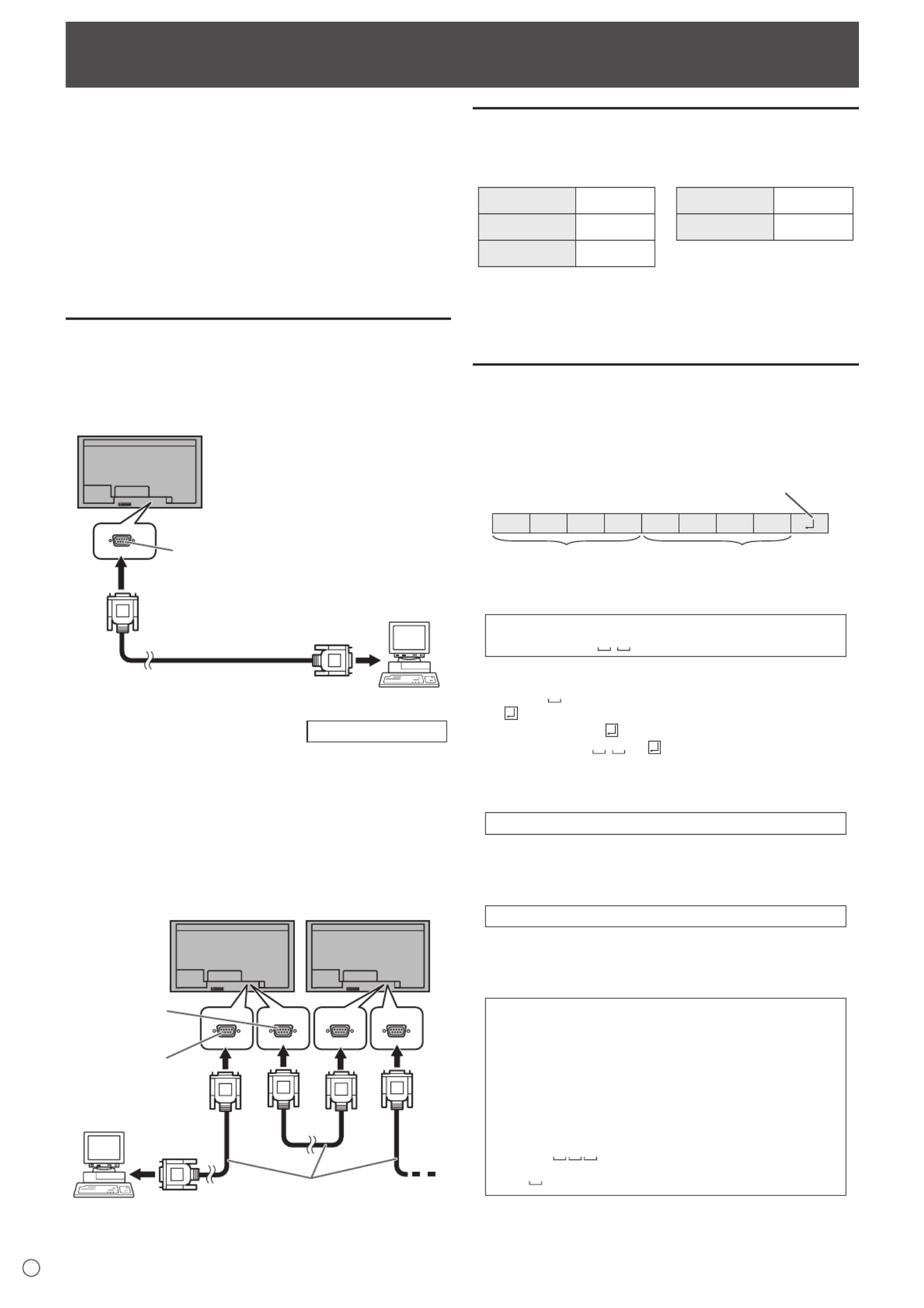
32
E
Controlling the Monitor with a PC (RS-232C)
YoucancontrolthismonitorfromaPCviaRS-232C(COM
port)onthePC.
You can also connect multiple monitors via a daisy chain by
usingaPC.ByassigningIDnumberstoeachmonitor(see
page34),youcanmakeinputmodeselection/adjustmentor
cancheckthestatusofaspecicmonitor.
Precautions when the PN-ZB02 (optional) is attached
• TocontrolthemonitorviaRS-232C,setRS-232C/LAN
SELECTtoRS-232C.
• YoucannotuseRS-232CandLANcontrolsimultaneously.
PC connection
nOne-to-one connection with a PC
ConnectwithRS-232straightcablebetweenthePC’sCOM
port(RS-232Cconnector)andtheRS-232Cinputterminalon
the monitor.
RS-232 straight cable
(commercially available)
To COM port
PC
RS-232C input terminal
nDaisy chain connection… Advanced operation
ConnectwithRS-232straightcablebetweenthePC’sCOM
port(RS-232Cconnector)andtheRS-232Cinputterminalon
therstmonitor.
Next,connectRS-232straightcabletotherstmonitor’s
RS-232Coutputterminalandtothesecondmonitor’s
RS-232Cinputterminal.Connectinthesamewaytothethird
andsubsequentmonitors.
Upto25monitorscanbeconnected.(Dependingonthe
length of the cable used and the surrounding environment.)
RS-232 straight cables
(commercially available)
First monitor Second monitor
PC
To COM port
RS-232C
input terminal
RS-232C
output terminal
Communication conditions
SettheRS-232CcommunicationsettingsonthePCtomatch
the monitor’s communication settings as follows:
Baudrate *
Stop bit
1bit
Datalength Flowcontrol8 bits None
Parity bit None
*SettothesamebaudrateastheBAUDRATEsettingof
SETUPmenu.(Initialsetting:38400bps)
*Whenconnectingmultiplemonitorsinadaisychain,setall
monitorstothesameBAUDRATE.
Communication procedure
nCommand format
WhenacommandissentfromthePCtothemonitor,the
monitor operates according to the received command and
sendsaresponsemessagetothePC.
C1 C2 C3 C4 P1 P2 P3 P4
Return code
Command field
(4 prescribed
alphanumerical characters
)
Parameter field
(4 character string comprised of:
0-9, +, -, space, ?)
Example:VOLM0030
VOLM 30
* Besuretoinput4charactersfortheparameter.Padwith
spaces (“ ”) if necessary.
(“ ”isareturncode(0DH,0AHor0DH))
Wrong :VOLM30
Right :VOLM 30
Wheninputtinganegativevalue,specifyanumericalvaluein
three digits.
Example:AUTR-005
DonotusespacesforMPOS,DATE,andSC01through
SC08.Specifyparametersusingaspeciednumberof
characters.
Example:MPOS010097
Ifacommandhas“R”listedfor“DIRECTION”inthe
“RS-232Ccommandtable”onpage37,thecurrentvaluecan
be returned by using “?” as the parameter.
Example:
VOLM???? ← FromPCtomonitor(Howmuch
is current volume setting?).
30 ← FrommonitortoPC(Current
volumesetting:30).
* IfanIDnumber(seepage33)hasbeenassigned
(Forexample,IDnumber=1).
VOLM ?←FromPCtomonitor.
30 001 ← FrommonitortoPC.
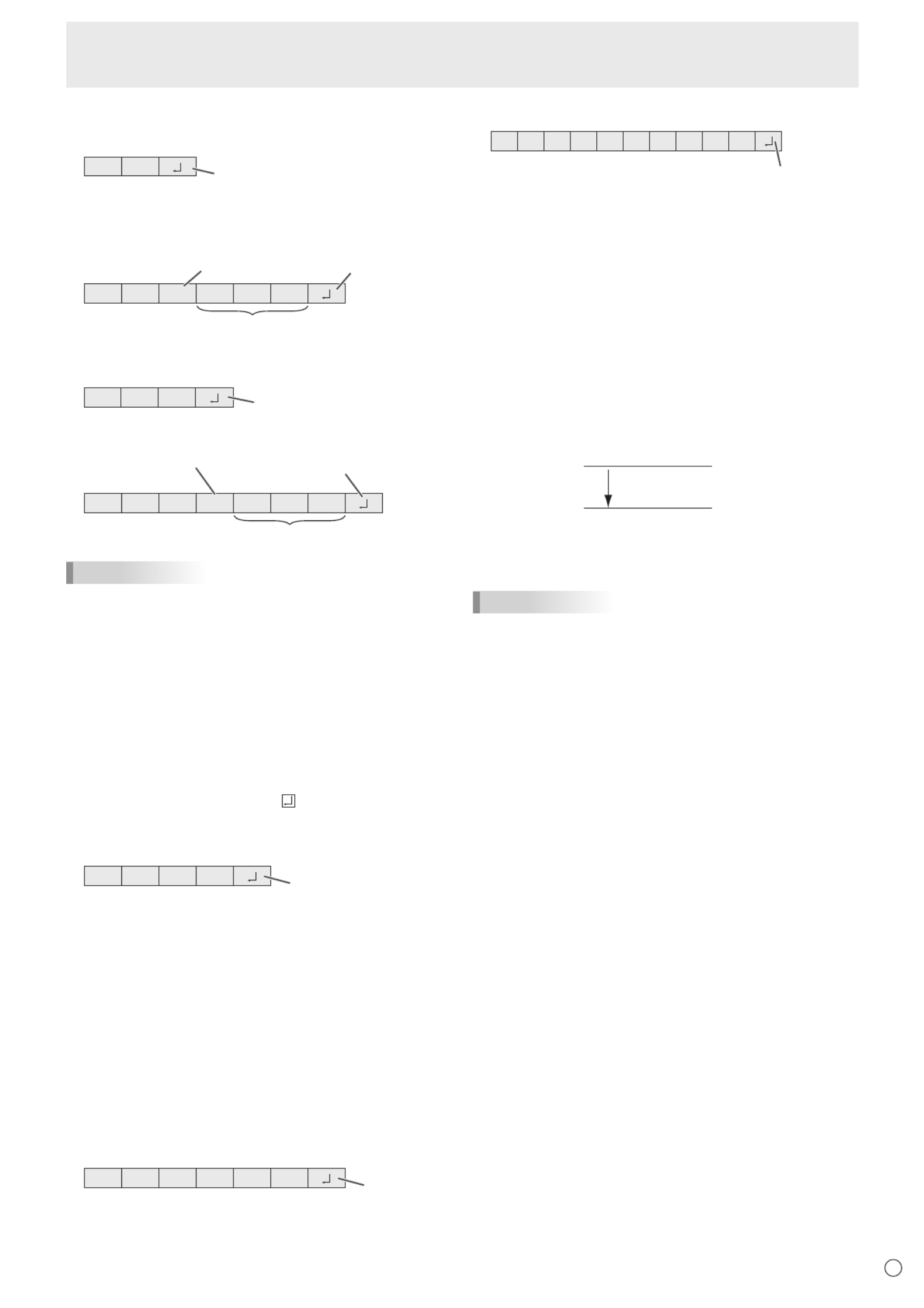
E
33
Controlling the Monitor with a PC (RS-232C)
nResponse code format
When a command has been executed correctly
O K Return code
(0D , 0A )H H
A response is returned after a command is executed.
* IfanIDnumberhasbeenassigned
O K SPC 0 0 1
ID number of respondin
g
monitor
Space (20H) Return code
(0D , 0A )H H
When a command has not been executed
R R E Return code
(0D , 0A )H H
* IfanIDnumberhasbeenassigned
R R E SPC 0 0 1
ID n
u
m
be
r
Space (20 ) HReturn code
(0D , 0A )H H
TIPS
• “ERR”isreturnedwhenthereisnorelevantcommandor
when the command cannot be used in the current state of
the monitor.
• Ifcommunicationhasnotbeenestablishedforreasons
suchasabadconnectionbetweenthePCandmonitor,
nothingisreturned(notevenERR).
• “ERR”maybereturnedwhenacommandcan’tbe
received correctly due to interference from the surrounding
environment.
Please ensure that the system or software retries the
command if this occurs.
• IfnomonitorhasbeenassignedthedesignatedIDnumber
(e.g.ifthecommandIDSL0002 is used, but no monitor
withIDnumber:2isfound),noresponseisreturned.
If execution of the command is taking some time
I W T A Return code
(0D , 0A )H H
Whenthefollowingcommandsareused,“WAIT”isreturned.
Inthiscase,avaluewillbereturnedifyouwaitawhile.Donot
send any command during this period.
NoIDnumberisattachedtoWAITresponse.
• CommandswhichreturnWAIT:
1. Whenrepeatercontrolisused
2. WhenanIDSLorIDLKcommandisused
3. Whenoneofthefollowingcommandsisused:RSET,
INPS,ASNC,WIDE,EMAG,EPOS,PXSL,POWR,
AGIN,MWIN,MWIP,MWPP,ESTG,EMHV,EPHV,
ESHV,ENLG
When control via RS-232C is locked (to prevent use)
using the operation lock function (see page 31)
E C D K O L Return code
(0DH H, 0A )
When RS-232C/LAN SELECT is set to LAN
U N S E E C E D L T
Return code
(0DH H, 0A )
nCommunication interval
• AfterOKorERRisreturned,youmustsendthefollowing
commands.
Tosetatimeoutforthecommandresponse,specify10
seconds or longer.
Whenconnectingmultiplemonitorsinadaisychain,setthe
timeout to at least the product of the monitor’s position from
thecomputermultipliedby10seconds.
Example)3rdmonitorfromcomputer:30secondsorlonger.
• Provideanintervalof100msormorebetweenthe
command response and the transmission of the next
command.
VOLM0020
OK
INPS0001
WAIT
OK
Interval of 100 ms or more
TIPS
• WhenexecutingALLRESET,setthetimeoutperiodto30
seconds or longer.
• WhenturningthepoweronwhilethePOWERONDELAY
functionisinuse,setthetimeoutperiodtothePOWERON
DELAYperiod+10secondsorlonger.

E34
Controlling the Monitor with a PC (RS-232C)
Advanced operation
This section explains commands for daisy chain connection.
The basic communication procedure is the same as in the
“One-to-oneconnectionwithaPC”section.
nID numbers
YoucanassignauniqueIDnumbertoeachmonitor(see
page 24). This allows you to control a particular monitor in a
daisy chain of monitors.
YoucanassignIDnumberseitherfromthemenuscreenor
fromthePCusingRS-232cable.
[E
xamp
l
e
]
ID number: 1 ID number: 2 ID number: 3 ID number: 4
If monitors are connected as shown above, you can
execute commands like “Set the volume of the monitor with
ID4to20”.
WhendesignatingIDnumbersforasetofmonitorslinkedina
daisychain,youshouldbasicallyavoidanyduplicationofID
numbers.
IDnumbersdonothavetobeassignedinascendingorder
startingfromthePC.Theycanalsobeconnectedasshown
below.
[E
xamp
l
e
]
ID number: 3 ID number: 2 ID number: 4 ID number: 1
nCommands for ID control
The command examples shown on this page assume the
followingconnectionandIDnumbersetup.
ID number: 1 ID number: 2 ID number: 3 ID number: 4
IDST .........AmonitorreceivingthiscommandsetsitsownID
numberintheparametereld.
Example:
IDST0001
OK 001 ← TheIDnumberofthismonitorissetto1.
TIPS
YoucanautomaticallyassignIDnumbersbyusingtheIDST
command with the Repeater control (see “Repeater control”
onpage35).
Forexample,usingthecommand“IDST001+”automatically
setstheIDnumbers,asshownbelow.
[E
xamp
l
e
]
ID number: 1 ID number: 2 ID number: 3 ID number: 4
IDST001+ ← IDsettingcommandwithrepeatercontrol
WAIT
OK 001 ← “OK”responsefromIDnumber:1
OK 002 ← “OK”responsefromIDnumber:2
OK 003 ← “OK”responsefromIDnumber:3
OK 004 ← “OK”responsefromIDnumber:4(End)
IDSL ........TheparameterofthiscommandsetstheIDnumber
ofthemonitor.Themonitorissubjecttothenext
command.
Example:
IDSL0002 ←
The next command is for the monitor
withIDnumber:2.
WAIT ← SearchingformonitorwithIDnumber:
2
OK 002 ←
FoundmonitorwithIDnumber:2
VOLM0030 ← SetsvolumeofmonitorwithID
number:2to30.
WAIT ← Processing
OK 002 ← OKresponsefrommonitorwithID
number: 2
VOLM0020 ← Setsvolumeto20.
OK 001 ←
ThevolumeofthemonitorwithID
number:1(theonedirectlyconnected
tothePC)issetto20.*
* TheIDSLcommandiseffectiveonlyonce,forthe
immediately succeeding command.

E
35
Controlling the Monitor with a PC (RS-232C)
IDLK ........
TheparameterofthiscommandsetstheID
numberofthemonitor.Themonitorissubjecttoall
subsequentcommands.
Example:
IDLK0002 ←
Followingcommandsareforthemonitor
withIDnumber:2.
WAIT ← SearchingformonitorwithIDnumber:
2
OK 002 ←
FoundmonitorwithIDnumber:2
VOLM0030 ← SetsvolumeofmonitorwithID
number:2to30.*
WAIT ← Processing
OK 002
VOLM0020 ← SetsvolumeofmonitorwithID
number:2to20.*
WAIT
OK 002
IDLK0000 ← CancelingxedIDnumbersetting
WAIT ← CancelingIDLK
OK 002 ← Cancelationcomplete
VOLM0010
OK 001 ←
ThevolumeofthemonitorwithIDnumber:
1(theonedirectlyconnectedtothePC)is
setto10.(IDLKiscanceled.)
* TheIDLKcommandremainseffectiveuntilitis
canceled, or power is shut off.
IDCK ........ProvidesscreendisplayoftheIDnumbercurrently
assignedtoamonitor,andtheIDnumbercurrently
setforIDLK(ifany).
Example:
(AfterexecutingIDLK0002)
IDCK0000 ←(Parameter has no meaning.)
ID:001IDLK:002 ←
Returnedresponse.TheID
number is also displayed on the
monitor screen.
IDCK000+ ←Repeater control. (If a command
isusedwithrepeatercontrol,ID
designationusingIDSLorIDLK
is canceled.)
WAIT
ID:001IDLK:000
ID:002IDLK:000
ID:003IDLK:000
ID:004IDLK:000
nRepeater control
This system has a function to allow setting of multiple
monitors connected in a daisy chain using a single command.
This function is called repeater control. You can use Repeater
controlfunctionwithoutassigningIDnumbers.
[E
xamp
l
e
]
Set 1
Set 2 Set 3 Set 4
* If monitors are connected as shown above, you can
execute a command like “Set all monitors’ input settings to
PCD-SUB”.
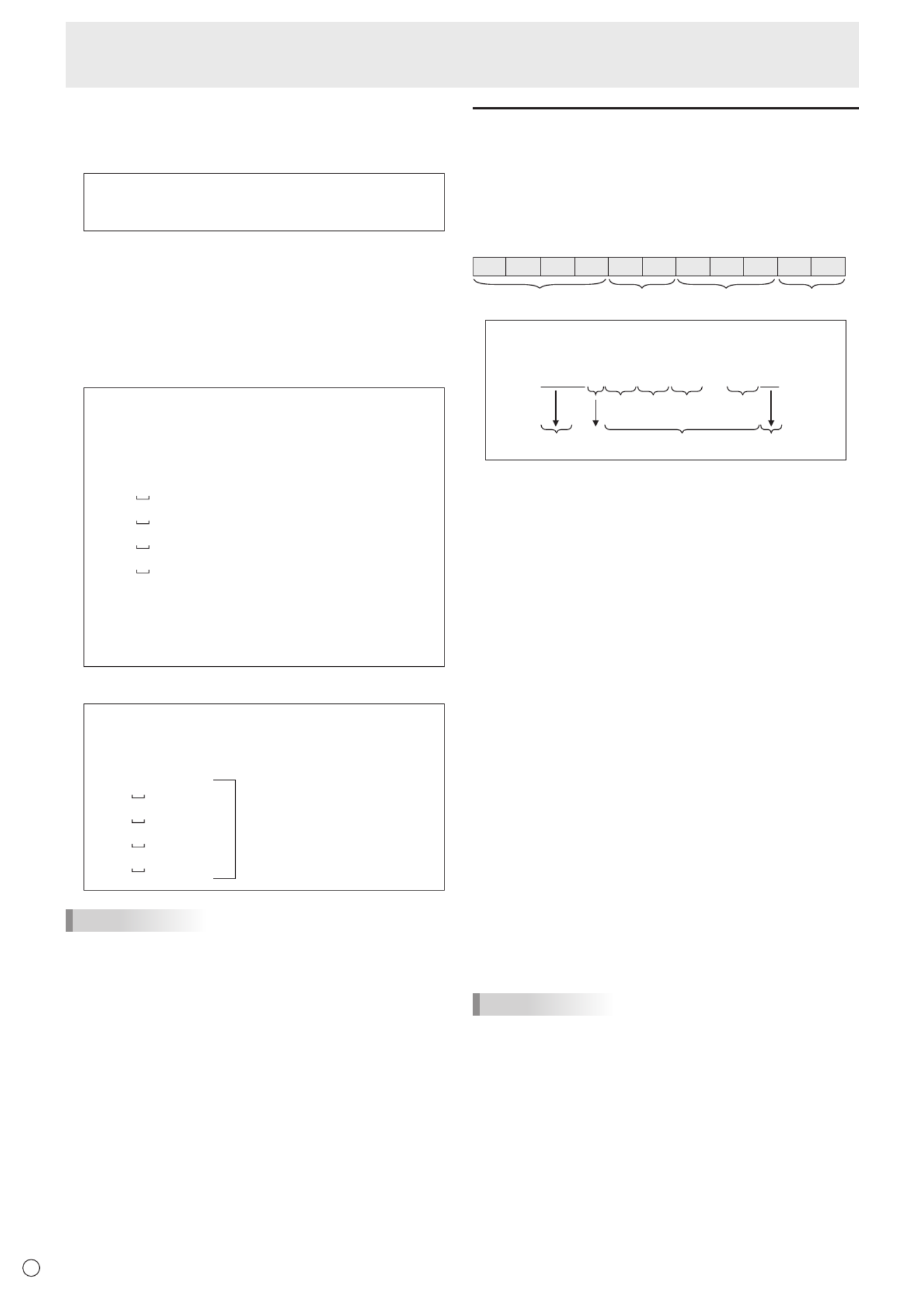
E36
nRepeater control command
RepeatercontrolisachievedbysettingtheFOURTH
CHARACTERoftheparameterto“+”.
Example:
VOLM030+ ← Setsvolumeofallmonitorsto30.
In repeater control, responses are returned by all the
connected monitors.
If you want to determine that a value has been returned by a
specicset,assignIDnumberstoeachmonitorinadvance.
Whensomemonitorsdonotreturntheirresponses,the
probable cause is that the monitors could not receive the
commandorcommandprocessingisnotcomplete.Donot
send a new command.
Example: (When4monitorsareconnected,and
assignedIDnumbers:1through4)
VOLM030+
WAIT
OK 001
OK 002
OK 003
OK 004 ← If 4 monitors are connected in
a chain, reliable operation can
be ensured by sending a new
command only after a reply
has been returned by 4th (last)
monitor.
Repeater control can also be used for reading settings.
Example:
VOLM???+
WAIT
10 001
Volumesettingsforall
monitors are returned.
20 002
30 003
30 004
TIPS
• IfrepeatercontrolisusedduringIDdesignation(IDSL,
IDLK),theIDdesignationiscanceled.
Controlling the Monitor with a PC (RS-232C)
Setting of the GAMMA user data
nTo transfer the GAMMA user data
Usetheuserdatatransfercommands(UGRW,UGGWand
UGBW).ForeachoftheR,GandBcolors,dividethetotal
512piecesofuserdatainto16blocks,andtransfer32pieces
of data with each command.
C1 C2 C3 C4 P1 P2 P3 P4 …S1 S2
Command field
Block number (01 to 16)
Data field Checksum field
Example:Totransferthedataofblock1(0to31levels)
of red (R) data
UG 01000000010002 … 0031C0RW
Command
Block number
32 pieces of data Checksum
One piece of data consists
of 4 digits.
* Ifdataislessthan4digits,adda“0”(zero)tomakeit4
digits.
* Thechecksumeldisthecharacterstring(ASCII)dataof
lower-orderonebytewhichindicatesthesumoftheblock
numberand32piecesofdatainhexadecimal(0toF).
nSaving the GAMMA user data
Usetheuserdatasavecommand(UGSV)tosavethe
transferred user data in the monitor.
If the data is not saved, it will be cleared when:
• Themainpowerswitchisoff
• STANDBYMODEisLOWPOWERandthemonitorenters
standby mode
nActivating the GAMMA user data
Toactivatethetransferreduserdata,selectUSERforGAMMA
ofthePICTUREmenu,orsendthecorrespondingRS-232C
command.
nChecking the GAMMA user data
Usetheuserdatareadcommands(UGRR,UGGRand
UGBR)toreturn512piecesofuserdataforeachoftheR,
GandBcolors.Dividethedatainto16blocksandreturn32
pieces of data with each command. The value to be returned
is not the value stored in the monitor, but the value in the
temporary memory for display. (These values are the same
whentheuserdatasavecommand(UGSV)abovehasbeen
sent.)
TIPS
• TheuserdataisnotinitializedbyRESETofthePICTURE
menu.Toinitializetheuserdata,useALLRESETofthe
FUNCTIONmenu.
TheGAMMAuserdatainitializecommand(UGRS)allows
theinitializationoftheuserdataonly.
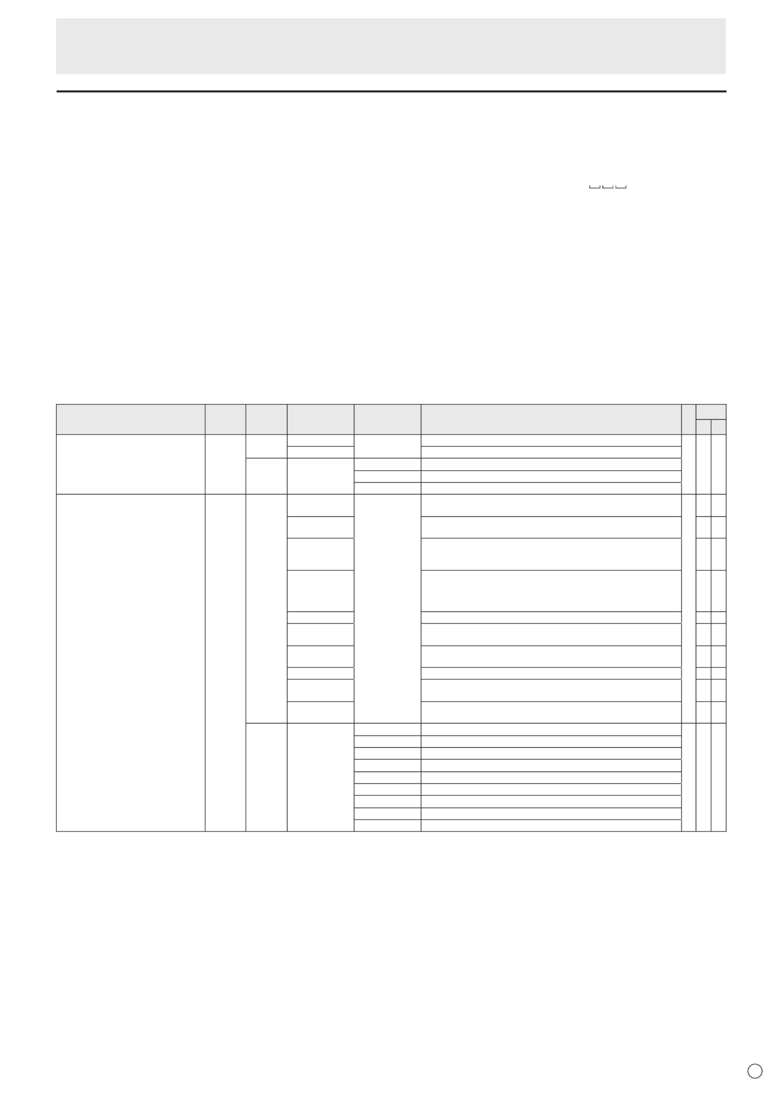
E
37
RS-232C command table
How to read the command table
Command: Commandeld(Seepage32.)
Direction: W Whenthe“Parameter”issetintheparametereld(seepage32),thecommandfunctionsasdescribed
under“Control/ResponseContents”.
R The returned value indicated under “Reply” can be obtained by setting “????”, “ ?”or“???+”
(repeatercontrol)intheparametereld(seepage32).
Parameter: Parametereld(Seepage32.)
Reply: Response (Returned value)
*1:
“●”
indicatesacommandwhichcanbeusedinpowerstandbymoderegardlessoftheSTANDBYMODE
setting.
“○”indicatesacommandwhichcanalsobeusedinpowerstandbymodewhenSTANDBYMODEissetto
STANDARD.
“–”indicatesacommandwhichcannotbeusedinpowerstandbymoderegardlessoftheSTANDBYMODEsetting.
*2: PN-ZB02(optional)limitations
(A)WhenPN-ZB02(optional)isnotattached,(B)WhenPN-ZB02(optional)isattached.
○:Thecommandcanbeused.
- :Error(ERR)
Power control/Input mode selection
Function
Command Direction
Parameter Reply Control/Response contents *1 *2
(A) (B)
POWERCONTROL POWR W 0 Switches to standby mode.
●○○
1Returns from standby mode.
R Standby mode0
1Normal mode
2 Input signal waiting mode
INPUTMODESELECTION W 0 Togglechangeforinputmode.TerminalsnotselectedinINPUTSELECTINPS
cannot be selected.
●
○ ○
1 PCDVI-D
“ERR”whenAVDVI-DisselectedforDVIofINPUTSELECT. -○
2 PCD-SUB
“ERR”whenotherthanPCD-SUBisselectedforD-SUBofINPUT
SELECT. ○ ○
3AVCOMPONENT(BNC)/AVCOMPONENT(D-SUB)
“ERR”whenotherthanPCRGBisselectedforBNCofINPUTSELECT,
andwhenotherthanAVCOMPONENTisselectedforD-SUBofINPUT
SELECT.
○ ○
4AVVIDEO(BNC)/AVVIDEO(D-SUB) ○ ○
6PCRGB
“ERR”whenAVCOMPONENTisselectedforBNCofINPUTSELECT. -○
7AVDVI-D
“ERR”whenPCDVI-DisselectedforDVIofINPUTSELECT. -○
8AVS-VIDEO - ○
9AVHDMI
“ERR”whenPCHDMIisselectedforHDMIofINPUTSELECT. ○ ○
10 PCHDMI
“ERR”whenAVHDMIisselectedforHDMIofINPUTSELECT. ○ ○
R1 PCDVI-D
●○○
2PCD-SUB
3AVCOMPONENT
4AVVIDEO
6PCRGB
7AVDVI-D
8AVS-VIDEO
9AVHDMI
10 PCHDMI
Controlling the Monitor with a PC (RS-232C)
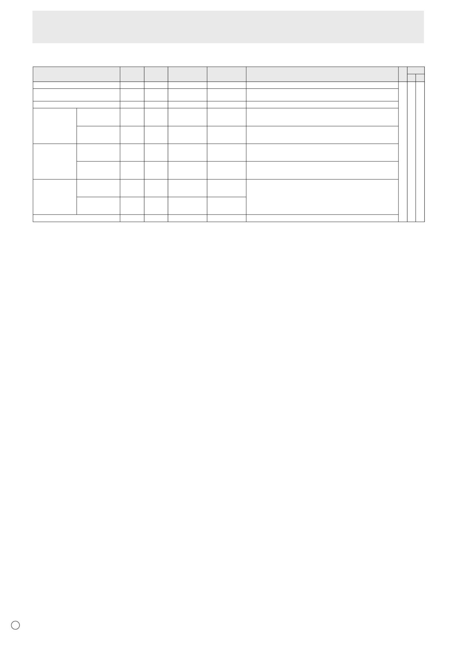
E38
SCREEN menu
Function
Command Direction
Parameter Reply Control/Response contents *1 *2
(A) (B)
AUTO ASNC W 1 WhentheinputmodeisPCD-SUB,PCRGB.
-○ ○
CLOCK CLCK WR 0-1200 0-1200 WhentheinputmodeisPCD-SUB,PCRGB.
Variesdependingonthesignal.
PHASE PHSE WR 0-63 0-63 WhentheinputmodeisPCD-SUB,PCRGB.
POSITIONING POSITIONOF
THELONGEST
DIRECTION
HPOS WR 0-100 0-100 0-800onPCD-SUB,PCRGB.
Variesdependingonthesignal.
POSITIONOF
THESHORTEST
DIRECTION
VPOS WR 0-100 0-100 0-200onPCD-SUB,PCRGB.
Variesdependingonthesignal.
SIZE POSITIONOF
THELONGEST
DIRECTION
HSIZ WR 0-100 0-100
POSITIONOF
THESHORTEST
DIRECTION
VSIZ WR 0-100 0-100
RESOLUTION
LONGEST
DIRECTION
RESOLUTION
HRES WR 300-1920 300-1920 WhentheinputmodeisPCD-SUB,PCRGB.
Only even numbers are valid for parameters.
Variesdependingonthesignal.
SHORTEST
DIRECTION
RESOLUTION
VRES WR 200-1200 200-1200
RESET W 1ARST
Controlling the Monitor with a PC (RS-232C)

E
39
PICTURE menu
Function
Command Direction
Parameter Reply Control/Response contents *1 *2
(A) (B)
AUTO AGIN W 1 WhentheinputmodeisPCD-SUB,PCRGB. -
○
○
ANALOGGAIN ANGA WR 0-127 0-127 WhentheinputmodeisPCD-SUB,PCRGB.
○
ANALOGOFFSET ANOF WR 0-127 0-127 WhentheinputmodeisPCD-SUB,PCRGB.
CONTRAST CONT WR 0-60 0-60
BLACKLEVEL BLVL WR 0-60 0-60
TINT TINT WR 0-60 0-60
COLORS COLR WR 0-60 0-60
SHARPNESS SHRP WR 0-24 0-24
RGBINPUTRANGE(AVHDMI) AHDR WR 0-2 0-2 0:AUTO,1:FULL,2:LIMITED
RGBINPUTRANGE(PCHDMI) PHDR WR 0-2 0-2 0:AUTO,1:FULL,2:LIMITED
RGBINPUTRANGE(AVDVI) ADVR WR 1-2 1-2 1:FULL,2:LIMITED
RGBINPUTRANGE(PCDVI) PDVR WR 1-2 1-2 1:FULL,2:LIMITED
RGBINPUTRANGE(D-SUB) PDSR WR 1-2 1-2 1:FULL,2:LIMITED
RGBINPUTRANGE(PCBNC) PBRR WR 1-2 1-2 1:FULL,2:LIMITED
ADVANCED
(Whentheinput
modeisAV.)
FLESHTONE FLES WR 0-2 0-2 0:OFF,1:LOW,2:HIGH
○
○
3D-NR TDNR WR 0-2 0-2 0:OFF,1:LOW,2:HIGH
MPEG-NR WR 0-1 0-1 0:OFF,1:ONMPNR
3D-Y/C YCSP WR 0-1 0-1 0:OFF,1:ON(WhentheinputmodeisAVVIDEO)
C.M.S.-HUE CMHR WR -10-10 -10-10 R
○
CMHY Y
CMHG G
CMHC C
CMHB B
CMHM M
CRST W 1 Resets the hue.
C.M.S.-
SATURATION
CMSR WR -10-10 -10-10 R
CMSY Y
CMSG G
CMSC C
CMSB B
CMSM M
CRST W 2 Resets the saturation.
C.M.S.-VALUE CMVR WR -10-10 -10-10 R
CMVY Y
CMVG G
CMVC C
CMVB B
CMVM M
CRST W 3 Resets the brightness.
COLORMODE BMOD WR 0 0 STD
○
2 2 VIVID
3 3 sRGB(WhentheinputmodeisPC)
4 4 HIGHILLUMINANCE
WHITEBALANCE THRU CTMP WR 0 0 WhentheinputmodeisPCDVI-D/PCHDMI.
○
PRESET 1-18 1-18 From1:approximately3,000Kto15:approximately10,000K
(500Ksteps)
16:approximately5,600K,17:approximately9,300K,
18:approximately3,200K
USER 99 99
R-CONTRAST CRTR WR 0-256 0-256 “ERR”whenCTMPisnotsetto99.
G-CONTRAST CRTG WR 0-256 0-256
B-CONTRAST CRTB WR 0-256 0-256
R-OFFSET OFSR WR -127-127 -127-127
G-OFFSET OFSG WR -127-127 -127-127
B-OFFSET OFSB WR -127-127 -127-127
COPYTOUSER CPTU W 0 Copiesapresetvaluetotheusersetting. -
GAMMA GAMM WR 0-2 0-2 0:1.8,1:2.2,2:2.4(duringPCinput)
0:LIGHT2,2:DARK(duringAVinput)
○
4-6 4-6 4:USER,5:2.0,6:STD(duringPCinput)
4:USER,5:LIGHT1,6:STD(duringAVinput)
LOCALDIMMING LODI WR 0-3 0-3 0:OFF,1:LOW,2:MIDDLE,3:HIGH
POWERLIMITED PWSV WR 0-2 0-2 0:OFF,1:MODE1,2:MODE2
“ERR”whenLOCALDIMMINGisnotsettoHIGH.
DISPLAYCOLORPATTERN PTDF WR 0 0 No pattern display.
1 1 Whitesinglecolorpatterndisplay.
2 2 Red single color pattern display.
3 3 Greensinglecolorpatterndisplay.
4 4 Bluesinglecolorpatterndisplay.
99 99 Red/green/blue mixed color pattern display.
Seteachcolor'slevelwithRED,GREEN,BLUE.
RED PTDR WR 0-15 0-15 “ERR”whenPTDFisnotsetto99.
GREEN PTDG WR 0-15 0-15
BLUE PTDB WR 0-15 0-15
RESET WARST 2 -
Controlling the Monitor with a PC (RS-232C)
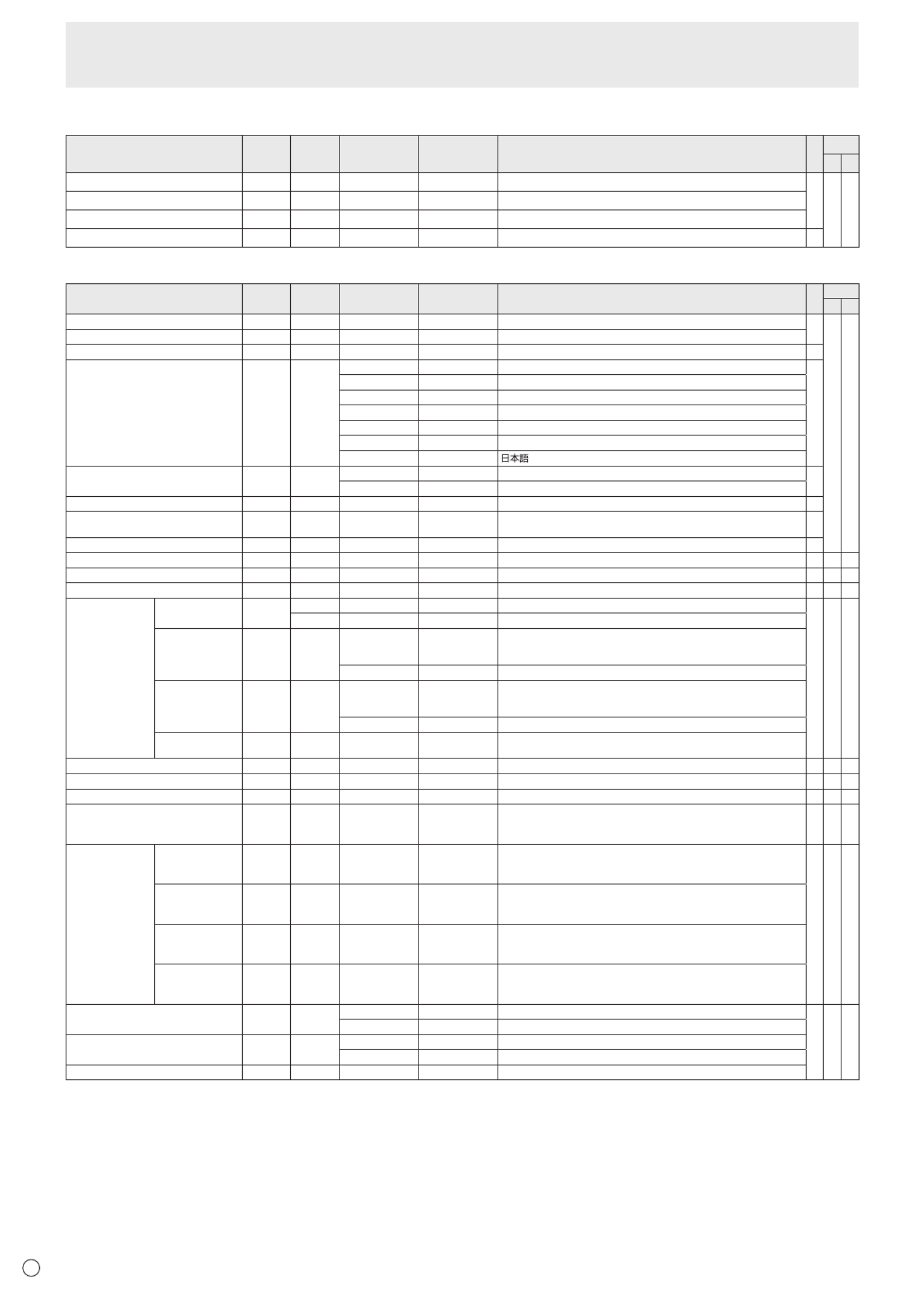
E40
AUDIO menu
Function
Command Direction
Parameter Reply Control/Response contents *1 *2
(A) (B)
TREBLE WR -5-5 -5-5AUTR
○○ ○
BASS AUBS WR -5-5 -5-5
BALANCE AUBL WR -10-10 -10-10
RESET WARST 3 -
SETUP menu
Function
Command Direction
Parameter Reply Control/Response contents *1 *2
(A) (B)
OSDH-POSITION OSDH WR 0-100 0-100 ○
○ ○
OSDV-POSITION OSDV WR 0-100 0-100
MONITOR STDR WR 0-1 0-1 0:LANDSCAPE,1:PORTRAIT ○
LANGUAGE LANG WR 14 14 ENGLISH
○
1 1 DEUTSCH
2 2 FRANÇAIS
3 3 ITALIANO
4 4 ESPAÑOL
5 5 РУССКИЙ
6 6
POWERONDELAY PWOD WR 0 0 OFF ○
1-60 1-60 ON
OPERATIONMODE FNCM WR 0-1 0-1 0:MODE1,1:MODE2 ○
STANDBYMODE STBM WR 0-1 0-1 0:STANDARD,1:LOWPOWER
(“ERR”whenSCHEDULEiseffectiveorOFFisselectedforLED.) ○
OFFIFNOOPERATION ATOF WR 0-1 0-1 0:OFF,1:ON ○
HOTPLUGCONTROL(DVI) HPCT WR 0-1 0-1 0:OFF,1:ON ○-○
HOTPLUGCONTROL(HDMI) HPCH WR 0-1 0-1 0:OFF,1:ON ○○○
RS-232C/LANSELECT CTLS WR 0-1 0-1 0:RS-232C,1:LAN ○-○
IDNUMBER IDNO.SETTING IDST W 0-255 Setsthemonitor’sIDnumber.(“0”means“noIDnumber”.)
○○○
R0-255 Returnsthemonitor’sIDnumber.
IDNO.SETTING
(ONCE)
IDSL W 1-255 SetsamonitorIDnumber.
ThisIDnumberisonlyeffectiveforthecommandimmediatelyafterthis
command.
0 ClearstheIDnumberifonehasbeendesignated.
IDNO.SETTING
(SUBSEQUENT)
IDLK W 1-255 SetsamonitorIDnumber.
ThisIDnumberiseffectiveforthenextandallsubsequentcommands
after this command.
0 ClearstheIDnumberifonehasbeendesignated.
IDCHECK IDCK W 0 ID :xxx
IDLK :yyy
Displaysmonitor’sownIDnumberandtheselectedIDnumberonthe
screen.
BAUDRATE BAUD WR 0-2 0-2 0:9600bps,1:19200bps,2:38400bps ○○○
OPTIONDCOUTSETTING DCOT WR 0-2 0-2 0:OFF,1:MODE1,2:MODE2 - ○ ○
HDMIAUTOVIEW HDAW WR 0-1 0-1 0:OFF,1:ON ○○○
BRIGHTNESSSENSOR(When
connectedtothePN-ZR01(optional)
only)
OPTS WR 0-2 0-2 0:OFF,1:ON,2:ON:DISPLAY ○○○
BRIGHTNESS
SENSOR
SETTING(When
connected to
thePN-ZR01
(optional) only)
WHENDARK:
AMBIENT
BRIGHTNESS
OPSD WR 0-99 0-99
○○○
WHENDARK:
SCREEN
BRIGHTNESS
OPDD WR 0-30 0-30
WHENLIGHT:
AMBIENT
BRIGHTNESS
OPSL WR 1-100 1-100
WHENLIGHT:
SCREEN
BRIGHTNESS
OPDL WR 1-31 1-31
SETTINGCOPYMODE CPMD WR 0 0 Copytoallmonitors.
○○○
1-225 1-225 CopytothemonitorwiththesetIDNumber.
SETTINGCOPYTARGET CPTG WR 0 0 CopiesthePICTUREmenusettings.
1 1 Copiesallthesettings.
LOGOSCREEN BTSC WR 0-1 0-1 0:OFF,1:ON
Controlling the Monitor with a PC (RS-232C)

E
41
Controlling the Monitor with a PC (RS-232C)
OPTION menu
Function
Command Direction
Parameter Reply Control/Response contents *1 *2
(A) (B)
DATE/TIMESETTING DATE WR
AABBCCDDEE AABBCCDDEE
AA:Year,BB:Month,CC:Day,DD:Time,EE:Minute
○○○
DATEDISPLAYFORMAT DTFT WR
0-2 0-2
0:YYYY/MM/DD,1:MM/DD/YYYY,2:DD/MM/YYYY
YYYY:Year,MM:Month,DD:Day
TIMEDISPLAYFORMAT TMFT WR
0-1 0-1
0:24-HOURTIME,1:12-HOURTIME
SCHEDULE SC01-
SC08
WR ABCDEFFGGH ABCDEFFGGH Scheduleofaspeciednumber
A:Schedule 0=Noteffective,1=Effective
B:Power 0=OFF,1=ON
C:Dayoftheweek1 0=Onlyonce,1=Everyweek,2=Everyday
D:Dayoftheweek2 0=Sunday,1=Mondaythrough6=Saturday,
9=Notexist
E:Dayoftheweek3 0=Sunday,1=Mondaythrough6=Saturday,
9=Notexist
F:Time 00-23
G:Minute 00-59
H:Input 0=Notspecied,1=PCDVI-D/AVDVI-D,
2=PCD-SUB,3=PCRGB/AVCOMPONENT,
4=AVVIDEO,5=AVS-VIDEO,
6=PCHDMI/AVHDMI
“ERR”whenLOWPOWERisselectedforSTANDBYMODE.
SCHEDULEBRIGHTNESS SB01-
SB08
WR 0-31 0-31 Screen brightness to change
99 99 Disablebrightnesssetting
INPUTSELECT DVI DVSL WR 0-1 0-1 0:PCDVI-D,1:AVDVI-D ○-
○
BNC BNSL WR 0-1 0-1 0:PCRGB,1:AVCOMPONENT ○-
D-SUB SLDS WR 0-2 0-2 0:PCD-SUB,1:AVCOMPONENT,2:AVVIDEO ○ ○
HDMI HDSL WR 0-1 0-1 0:PCHDMI,1:AVHDMI ○ ○
AUDIOSELECT PCDVI-D ASDP WR 1-3 1-3 1:AUDIO(STEREOMINI),2:AUDIO1(RCA),3:AUDIO2(RCA)
○
-
PCD-SUB WR 1-3 1-3 1:AUDIO(STEREOMINI)ASAP ○
2:AUDIO1(RCA),3:AUDIO2(RCA) -
PCHDMI ASHP WR 0-1 0-1 0:HDMI,1:AUDIO(STEREOMINI) ○
2-3 2-3 2:AUDIO1(RCA),3:AUDIO2(RCA) -
PCRGB ASCP WR 1-3 1-3 1:AUDIO(STEREOMINI),2:AUDIO1(RCA),3:AUDIO2(RCA) -
AVDVI-D ASDA WR 1-3 1-3 1:AUDIO(STEREOMINI),2:AUDIO1(RCA),3:AUDIO2(RCA) -
AVHDMI ASHA WR 0-1 0-1 0:HDMI,1:AUDIO(STEREOMINI) ○
2-3 2-3 2:AUDIO1(RCA),3:AUDIO2(RCA) -
AVCOMPONENT
(BNC)
ASCA WR 1-3 1-3 1:AUDIO(STEREOMINI),2:AUDIO1(RCA),3:AUDIO2(RCA) -
AVCOMPONENT
(D-SUB)
ASC2 WR 1-3 1-3 1:AUDIO(STEREOMINI),2:AUDIO1(RCA),3:AUDIO2(RCA) ○
AVS-VIDEO WR 1-3 1-3 1:AUDIO(STEREOMINI),2:AUDIO1(RCA),3:AUDIO2(RCA) -ASSA
AVVIDEO(BNC) ASVA WR 1-3 1-3 1:AUDIO(STEREOMINI),2:AUDIO1(RCA),3:AUDIO2(RCA) -
AVVIDEO
(D-SUB)
ASV2 WR 1-3 1-3 1:AUDIO(STEREOMINI),2:AUDIO1(RCA),3:AUDIO2(RCA) ○
INPUT
RESOLUTION
(PC)
RESOLUTIONCHECK
PXCK -R Returns current resolution in the form of hhh, vvv.
-
○ ○
PIXELSETTING
(PCD-SUB,PC
RGB)
PXSL WR 0 0 768)1366x768
1 1 768)1360x768
2 2 768)1280x768
3 3 768)1024x768
5 5 480)848x480
6 6 480)640x480
7 7 1050)1680x1050
8 8 1050)1400x1050
9 9 768) AUTO
10 10 480)AUTO
INPUTRESOLUTION(AV)
RESOLUTIONCHECK
RESO - 480i,480p,1080i,720p,1080p,VGA,etc. -R
ZOOM2SPECIALSETTING
(PCD-SUB,PCRGB)
Z2SP WR 0-1 0-1 0:OFF,1:ON ○
SCANMODE SCAN WR 0-2 0-2 0:MODE1,1:MODE2,2:MODE3(WhentheinputmodeisAV) ○
POWERMANAGEMENT(PC) PMNG WR 0-1 0-1 0:OFF,1:ON ○
POWERMANAGEMENT(AV) PMAV WR 0-1 0-1 0:OFF,1:ON ○
COLORSYSTEM CSYS WR 0-5 0-5 0:AUTO,1:PAL,2:PAL-60,3:SECAM,4:NTSC3.58,5:NTSC4.43 ○○○
AUDIOOUTPUT(RCA) WR 0-1 0-1 0:VARIABLE,1:FIXEDAOUT ○ ○ -
AUDIOOUTPUT(RCA)
WhenthePN-ZB02(optional)isattached
AOUT WR 0-2 0-2 0:VARIABLE1,1:FIXED,2:VARIABLE2 ○-○
AUDIOLEVEL(STEREOMINI) AIVP WR 0-1 0-1 0:1.0Vrms,1:0.5Vrms ○
○ ○
SELFADJUST AADJ WR 0-1 0-1 0:OFF,1:ON ○
AUTOINPUTCHANGE AINC WR 0-1 0-1 0:OFF,1:ON ○
FANSPEED FCTL WR 0-4 0-4 0:AUTO,1-4:SPEED1-4 ○

E42
MULTI menu
Function
Command Direction
Parameter Reply Control/Response contents *1 *2
(A) (B)
ENLARGE ENLG WR 0-1 0-1 0:OFF,1:ON
-○ ○
ENLARGEMODE EMAG WR 0-4 0-4 0:OFF,1:2x2,2:3x3,3:4x4,4:5x5
EMHV WR 11-55 11-55 1x1(OFF)to5x5(“mxn”isexpressedas“mn”,wheremandnare
thenumbersofmonitorsspeciedforthelongestdirectionandthe
shortest direction respectively.)
IMAGEPOSITION(MxN) EPHV WR 11-55 11-55 SpeciesvaluesintheorderofIMAGEPOSITIONINLONGEST/
SHORTESTDIRECTION.
IMAGEPOSITION(2x2) EPOS WR 0-3 0-3 See the description below.
IMAGEPOSITION(3x3) EPOS WR 0-8 0-8
IMAGEPOSITION(4x4) EPOS WR 0-15 0-15
IMAGEPOSITION(5x5) EPOS WR 0-24 0-24
ENLARGED
SCREEN
POSITIONING
THELONGEST
DIRECTION
EPSH WR -999-999 -999-999 ThesettingrangedependsontheENLARGEMODEsettingandthe
IMAGEPOSITION.
THESHORTEST
DIRECTION
EPSV WR -999-999 -999-999
BEZELADJUST BZCO WR 0-1 0-1 0:OFF,1:ON
BEZELADJUST BZCT WR 0-1 0-1 0:OFF,1:ONTOP
BOTTOM BZCB WR 0-1 0-1 0:OFF,1:ON
RIGHT BZCR WR 0-1 0-1 0:OFF,1:ON
LEFT BZCL WR 0-1 0-1 0:OFF,1:ON
BEZELWIDTH BZWT WR 0-100 0-100TOP
BOTTOM BZWB WR 0-100 0-100
RIGHT BZWR WR 0-100 0-100
LEFT BZWL WR 0-100 0-100
ENLARGE/IMAGEPOSITIONSETTING ESTG WR XXYY XXYY XX:ENLARGEMODE(SameasEMAG),YY:IMAGEPOSITION(Same
asEPOS)
ESHV WR XXYY XXYY XX:ENLARGEMODE(SameasEMHV),YY:IMAGEPOSITION(Same
asEPHV)
• IMAGEPOSITION(EPOS)setting
In landscape orientation
2 x 2 4 x 4 5 x 53 x 3
1
3
0
2
0 1 2
3 4 5
6 7 8
2
6
10
3
7
11
01
4 5
8 9
12
13 14
15
0
5
10
15
20
1
6
11
16
21
2
7
12
17
22
3
8
13
18
23
4
9
14
19
24
In portrait orientation
2 x 2 4 x 4 5 x 53 x 3
13
02
0
1
2
4
5
6
8
9
10
3711
12
13
14
15
0
1
2
5
6
7
10
11
12
3813
15
16
17
18
20
21
22
23
4
9141924
0
1
2
3
4
5
6
7
8
Controlling the Monitor with a PC (RS-232C)

E
43
PIP/PbyP menu
Function
Command Direction
Parameter Reply Control/Response contents *1 *2
(A) (B)
PIPMODES MWIN WR 0-3 0-3 0:OFF,1:PIP,2:PbyP,3:PbyP2 ○
○ ○
PIPSIZE MPSZ WR 1-64 1-64 ○
PIP POS THELONGEST
DIRECTION
MHPS W 0-100 ○
R0-100 ○
THESHORTEST
DIRECTION
MVPS W 0-100 ○
R0-100 ○
PIPPOSLD+SDBATCH W 0-100,0-100MPOS Specify the position in MPOSxxxyyy format.
(xxx: Longer side, yyy: Shorter side position) ○
R Returns a response in (xxx,yyy) format. 0-100,0-100
(xxx: Longer side, yyy: Shorter side position) ○
PIPBLEND MWBL WR 0-15 0-15 ○
PIPSOURCE MWIP WR 1 1 PCDVI-D
○
-○
2 2 PCD-SUB ○ ○
3 3 AVCOMPONENT(BNC)/AVCOMPONENT(D-SUB) ○ ○
4 4 AVVIDEO(BNC)/AVVIDEO(D-SUB) ○ ○
6 6 PCRGB - ○
7 7 AVDVI-D - ○
8 8 AVS-VIDEO - ○
9 9 AVHDMI ○ ○
10 10 PCHDMI ○ ○
SOUNDCHANGE MWAD WR 1-2 1-2 1:MAIN,2:SUB ○
○ ○
MAIN POS (Main screen) MWPP WR 0-1 0-1 0:POS1,1:POS2 ○
PbyP2 POS (Sub screen) MW2P WR 0-2 0-2 0:POS1,1:POS2,2:POS3 ○
AUTOOFF MOFF WR 0-1 0-1 0:MANUAL,1:AUTO ○
Initialization/Functional Restriction Setting (FUNCTION) menu
Function
Command Direction
Parameter Reply Control/Response contents *1 *2
(A) (B)
ALLRESET RSET W 0 0:ALLRESET - ○-
0-1 0:ALLRESET1,1:ALLRESET2 - - ○
ADJUSTMENTLOCK ALCK WR 0-2 0-2 0:OFF,1:ON1,2:ON2 ○
○ ○
ADJUSTMENTLOCKTARGET ALTG WR 0-2 0-2 0:REMOTECONTROL,1:MONITORBUTTONS,2:BOTH ○
OSDDISPLAY LOSD WR 0-2 0-2 0:ON1,1:OFF,2:ON2 ○
LED OFLD WR 0-1 0-1 0:ON,1:OFF
“ERR”whenLOWPOWERisselectedforSTANDBYMODE. ○
TEMPERATUREALERT TALT WR 0-2 0-2 0:OFF,1:OSD&LED,2:LED ○
STATUSALERT SALT WR 0-2 0-2 0:OFF,1:OSD&LED,2:LED ○
POWERBUTTON PBTN WR 0-1 0-1 0:MONITOR,1:CONTROLLER ○
CONTROLLERINPUT PCIP WR 0-2 0-2 0:D-SUB,1:HDMI(“ERR”whenMONITORisselectedforPOWER
BUTTON.) ○ ○ ○
2:DVI-D(“ERR”whenMONITORisselectedforPOWERBUTTON.) ○-○
Controlling the Monitor with a PC (RS-232C)

E44
Others
Function
Command Direction
Parameter Reply Control/Response contents *1 *2
(A) (B)
SCREENSIZE(PC) WIDE WR 1-5 1-5 1:WIDE,2:NORMAL,3:DotbyDot,4:ZOOM1,5:ZOOM2 ○
○ ○
SCREENSIZE(AV) WIDE WR 1-5 1-5 1:WIDE,2:ZOOM1,3:ZOOM2,4:NORMAL,5:DotbyDot ○
VOLUME VOLM WR 0-31 0-31 ○
MUTE MUTE WR 0-1 0-1 0:OFF,1:ON -
INFORMATION MODEL INF1 ValueR●
SERIALNO ValueSRNO R
BRIGHT VLMP WR 0-31 0-31 ○
TEMPERATURESENSOR DSTA 0R Internal temperature normal
●
1Internal temperature abnormal (Standby mode)
2 Internal temperature abnormal (Temperature is normal now, but it was
abnormal during operation.)
3Internaltemperatureabnormal(Brightnessofthebacklightdecreases.)
4 Temperature sensor abnormal
TEMPERATUREACQUISITION ERRT Value Temperatureattemperaturesensors1through6arereturnedintheR
following forms:
[Sensor1],[Sensor2],[Sensor3],[Sensor4],[Sensor5],[Sensor6]
Indicatesatemperaturesensorabnormalitywhen“126”isreturned.
○
CAUSEOFLASTSTANDBYMODE STCA W 0 Initialization
●
R No detectable error has occurred0
1 StandbymodebyPOWERbutton
2 Main power off by the main power switch
3StandbymodebyRS-232CorLAN
4WaitingmodebyNoSignal
6 Standby mode by abnormal temperature
8StandbymodebySCHEDULEsetting
20 StandbymodebyOFFIFNOOPERATIONsetting
Commands for setting of the GAMMA user data
Function
Command Direction
Parameter Reply Control/Response contents *1 *2
(A) (B)
REDGAMMADATATRANSFER UGRW W aaxxxx
··· xxxxcc
(xxxx: 32 pieces)
aa:01-16
xxxx:0000-1023
cc:00-FF
aa:Blocknumber
xxxx: 32 pieces of user data
cc:Checksum(ASCIIdata)oftheblocknumberanduserdata
○ ○ ○
GREENGAMMADATATRANSFER UGGW W
BLUEGAMMADATATRANSFER UGBW W
REDGAMMADATAREAD UGRR W 1-16 xxxx
··· xxxx
(xxxx: 32 pieces)
xxxx:0000-1023
xxxx: User data of 32 pieces
GREENGAMMADATAREAD UGGR W 1-16
BLUEGAMMADATAREAD UGBR W 1-16
USERDATAINITIALIZE UGRS W 0 Initializetheuserdata.
USERDATASAVE UGSV W 0 Save the user data in the monitor.
Controlling the Monitor with a PC (RS-232C)
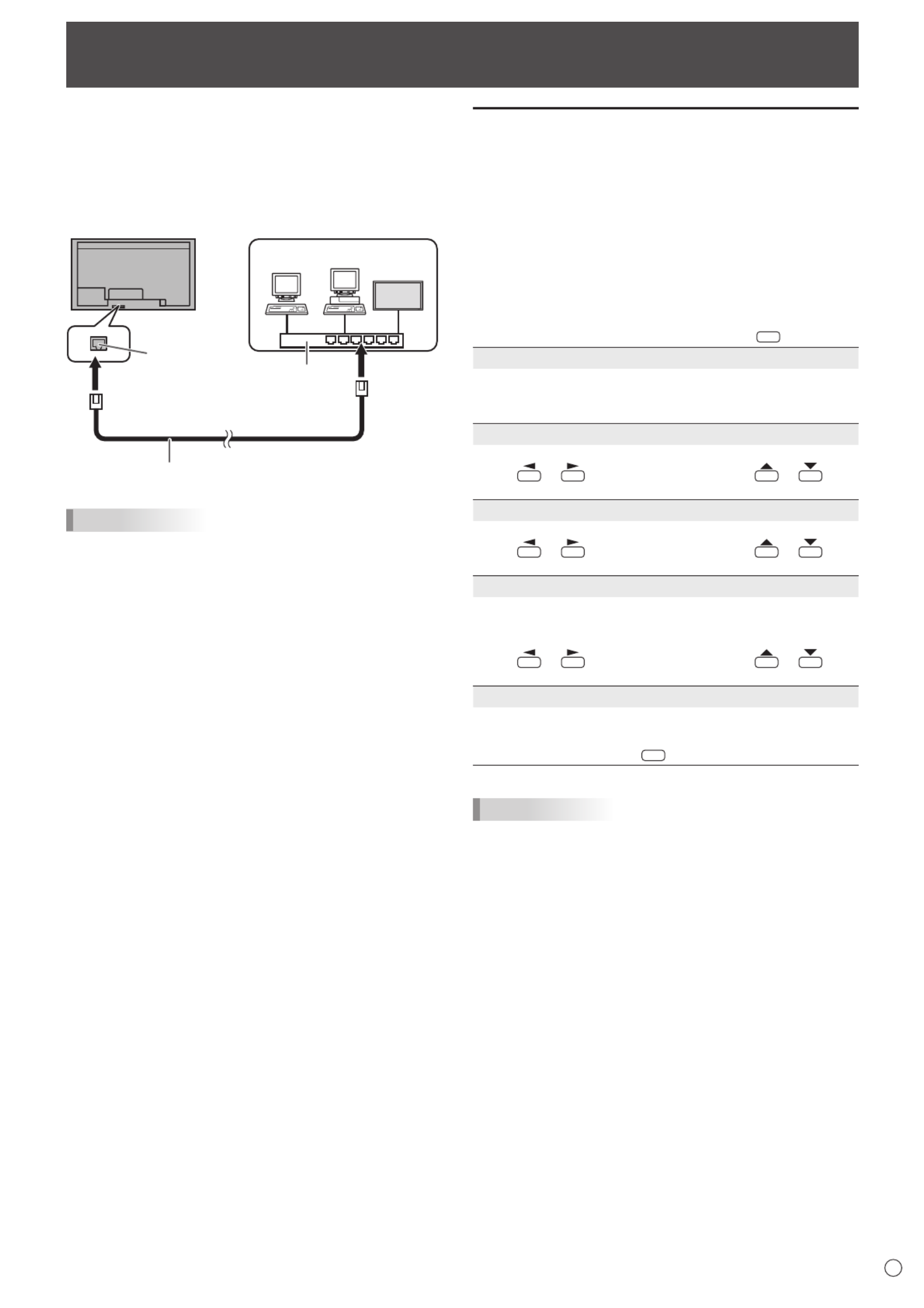
45 E
WhenthePN-ZB02(optional)isattached,yourmonitorcan
beconnectedtoaLANallowingyoutocontrolitfromaPCon
the LAN.
Youcanalsocongurethemonitortosende-mailnotication
when it has a problem.
TheconnectionrequiresacommerciallyavailableLANcable
(UTPcable,Category5,straightthrough).
Hub
LAN terminal
LAN cable (commercially available, straight)
Network (LAN)
TIPS
• YoumustassignanIPaddresstothemonitorbyfollowing
the procedures in “Settings to connect to a LAN”. (See the
description on the right.)
• YourPCmustbeinstalledwithInternetExplorer(version7.0
or later).
• TocontrolthemonitorviaLAN,setRS-232C/LANSELECT
to LAN. (See page 24.)
• YoucannotuseRS-232CandLANcontrolsimultaneously.
Initializing personal information
• WhenthePN-ZB02(optional)isattached,personal
informationsuchase-mailaddressescanberegisteredin
themonitor.Beforetransferringordisposingofthemonitor,
initializeallsettingsbyselectingALLRESET1.(See
page31.)NotethatALLRESET2willnotinitializee-mail
addresses and other settings.
Controlling the Monitor with a PC (LAN)
Settings to connect to a LAN
Set the monitor’s IP address and subnet mask to match the
settings of your LAN.
ThesesettingscanbemadeoneitherthemonitororaPC
connected to the monitor.
ThesettingsdependonthecongurationofyourLAN.Ask
your LAN administrator for details.
n
To set on the monitor
SetRS-232C/LANSELECTontheSETUPmenutoLAN,and
thensettheLANSETUPoptions.(Seepages24and25.)
Aftersettingeachitem,selectSETandpress
MENU
.
DHCP CLIENT
IfyourLANhasaDHCPserverandyouwishtoobtainan
address automatically, change this setting to ON.
Tosettheaddressmanually,setthistoOFF.
IP ADDRESS
IftheDHCPCLIENTissettoOFF,specifyanIPaddress.
Press or to select items, and press or to
change the values.
SUBNET MASK
IftheDHCPCLIENTissettoOFF,specifythesubnetmask.
Press or to select items, and press or to
change the values.
DEFAULT GATEWAY
IftheDHCPCLIENTissettoOFF,specifythedefault
gateway.
Ifyouarenotusingagateway,specify“0.0.0.0”.
Press or to select items, and press or to
change the values.
RESET
Resets the values of the LAN settings to the factory preset
values.
Select ON and then press
MENU
.
TIPS
• WhenmanuallysettingtheIPaddress,theIPaddress
forsecondarymonitorsconnectedbyRS-232Ccanbe
automaticallyallocated.(Seepage25.)

46
E46
n
To set from a PC
WhenthemonitorisconnectedtoaPC,LANsettingscanbe
conguredviaPC.
Set up process
(1)ConnectyourmonitortoaPC
(2)SpecifythePC’sIPaddress
(3)Congurethemonitor’sLANsettings
(1) Connecting your monitor to a PC
ConnectacommerciallyavailablecrossoverLANcable
(UPTcable,Category5)totheLANportonthePCandthis
monitor.
LAN cable (commercially available, crossover)
To LAN terminal
PC
LAN terminal
(2) Specifying the PC’s IP address
Tocongurethemonitor’sLANsettings,youmusttemporarily
changethesettingsonthePC.
ThisexplanationisbasedonWindows7.
1. LogontothePCwithanadministratoraccount.
2. Click[Start],andthenclick“ControlPanel”.
3. Click“Viewnetworkstatusandtasks”in“Networkand
Internet”.
In“ClassicView”,click“NetworkandSharingCenter”.
4. Click“LocalAreaConnection”andthen“Properties”.
5. Click“InternetProtocolVersion4(TCP/IPv4)”andthen
“Properties”.
6. Make a note of the current IP address, subnet mask, and
default gateway settings.
Make sure you write this information now as you will
be changing the IP address, subnet mask, and default
gateway settings back to these settings afterwards.
7. Temporarily change the IP address and subnet mask.
To access the monitor as it is shipped from the factory, set
as follows.
• IPAddress :192.168.150.1
• SubnetMask :255.255.255.0
• DefaultGateway :(leaveblank)
8. Click[OK]andthenrebootthePC.
TIPS
• Thismonitorisfactorypresetasshownbelow.
(WhenDHCPCLIENTissettoOFF)
IPAddress :192.168.150.2
SubnetMask :255.255.255.0
DefaultGateway :0.0.0.0
(3) Conguring the monitor’s LAN settings
AccessthemonitorusingInternetExplorer.
Controllingthemonitor
1. TurnthepowerONtothemonitor.
2. SetRS-232C/LANSELECTontheSETUPmenutoLAN.
3. SetDHCPCLIENTtoOFFinLANSETUPontheSETUP
menu.
PCoperation
4. LaunchInternetExplorer,inthe“Address”boxtype
“http://192.168.150.2/”andpresstheEnterkey.
You will be prompted to enter a user name and password.
5. Leavetheusernameandpasswordboxesblankandclick
[OK].
6. Clickon“LANSETUP”underNETWORK.
Controlling the Monitor with a PC (LAN)

47 E
47
7. Specifythe“DHCPCLIENT”,“IPADDRESS”,etc.
DHCP CLIENT
IfyourLANhasaDHCPserverandyouwishtoobtainan
address automatically, change this setting to ON.
Tosettheaddressmanually,setthistoOFF.
IP ADDRESS
IftheDHCPCLIENTissettoOFF,specifyanIPaddress.
SUBNET MASK
IftheDHCPCLIENTissettoOFF,specifythesubnet
mask.
DEFAULT GATEWAY
IftheDHCPCLIENTissettoOFF,specifythedefault
gateway.
Ifyouarenotusingadefaultgateway,specify“0.0.0.0”.
8. Whenthesettingischanged,click[Apply].
9. Checkthemessageandclick[OK].
10
.ExitInternetExplorer.
11.
RestorethePC’sIPaddressjottedinStep6,“(2)
SpecifyingthePC’sIPaddress”.
12.
ConnectthemonitorandthePCtotheLAN.
Caution
• Wait10secondsafterclicking[OK]beforeproceeding.
• Whenoperatingusingtheremotecontrolunitorsimilar,
click[Refresh].
TIPS
• WhenmanuallysettingtheIPaddress,theIPaddress
forsecondarymonitorsconnectedbyRS-232Ccanbe
automaticallyallocated.(Seepage25.)
Controlling with a PC
n
Basic operation
YouuseInternetExploreronaPContheLANtocontrolthe
monitor.
1. LaunchInternetExploreronthePC.
2.
In the “Address” box, type “http://” followed by your monitor’s
IPaddressfollowedby“/”,thenpresstheEnterkey.
YoucanconrmtheIPaddresswiththeDISPLAYfunction.
Whenpromptedtoenterausernameandpassword,type
theusernameandpasswordthatyouspeciedinthe
securitysettings(seepage49),andclick[OK].
If you did not make any security settings, leave the spaces
blankandclickon[OK].
3. You can check, control, and change the monitor’s status
and settings by clicking the menu items on the left side of
the screen.
• Ifyouseean[Apply]buttonnexttoasetting,clickitafter
you change that setting.
TIPS
• Seepages48to52fordetailsoneachsetting.
• Ifyouclick[Refresh]beforethescreennishesupdating
thecurrentdisplay,the“ServerBusyError”willappear.
Waitforamomentbeforeoperatingyourmonitoragain.
• Youcannotoperatethemonitorwhileitiswarmingup.
• IfDHCPCLIENTissettoON,press
DISPLA
Y
on the remote
control unit two times and then check the monitor’s IP
address.
Controlling the Monitor with a PC (LAN)

48
E48
n
INFORMATION
Information about this monitor appears.
n
CONTROL
You can control the operations corresponding to the buttons
(
POWER
INPUT
SIZE
)ontheremotecontrolunit.(Seepages18
and19.)
TIPS
• Instandbymode,PowerONistheoperationavailable.
n
ADJUSTMENT
Youcanadjustthesesettingswhicharealsoavailableonthe
monitor’s menu.
• SCREEN(Seepage23.)
• PICTURE(Seepage23.)
• PICTURE(ADVANCED)(Seepage30.)
• AUDIO(Seepage24.)
• SETUP(Seepage24.)
• OPTION(Seepage26.)
• SCHEDULE(Seepage29.)
• MULTI(Seepage27.)
• PIP/PbyP(Seepage27.)
• FUNCTION(Seepage31.)
TIPS
• AfterchangingDISPLAYCOLORPATTERNtoOFF,click
[Refresh]tocorrectlyretrievethestatusofthemonitor.
Controlling the Monitor with a PC (LAN)

49 E
49
n
NETWORK (LAN SETUP)
This screen allows you to set the settings necessary when the
monitor is connected to a LAN.
DHCP CLIENT
IfyourLANhasaDHCPserverandyouwishtoobtainan
address automatically, change this setting to ON.
Tosettheaddressmanually,setthistoOFF.
IP ADDRESS
IftheDHCPCLIENTissettoOFF,specifyanIPaddress.
SUBNET MASK
IftheDHCPCLIENTissettoOFF,specifythesubnetmask.
DEFAULT GATEWAY
IftheDHCPCLIENTissettoOFF,specifythedefault
gateway.
Ifyouarenotusingadefaultgateway,specify“0.0.0.0”.
DNS SERVER
SpecifytheDNSserveraddress.
IfyouarenotusingaDNSserver,specify“0.0.0.0”.
RESET
Clicking[Execute]returnsalloftheLANSETUPsettings
tothefactory-presetvaluesexceptfortheDNSSERVER
setting.
TIPS
• WhenmanuallysettingtheIPaddress,theIPaddress
forsecondarymonitorsconnectedbyRS-232Ccanbe
automaticallyallocated.(Seepage25.)
n
NETWORK (SECURITY)
Thisscreenallowsyoutospecifythesecurity-relatedsettings.
USER NAME / PASSWORD
Sets up a user name and password to restrict access to this
monitor.
Afterenteringausernameandpassword,click[Apply].
ACCEPT IP ADDRESS
You can limit access to this monitor by registering IP
addressesofPCsthatshouldhaveaccess.
Tolimitaccess,specifytheoption“FromonlyspecicIP
addresses”.Otherwise,toallowaccessfromanyPC,specify
“All IP Addresses”.
IP ADDRESS 1 to 3
If“ACCEPTIPADDRESS”issetto“FromonlyspecicIP
addresses”, enter the IP addresses that you want to allow.
TIPS
• TheUSERNAMEandPASSWORDcanbeupto8
alphanumeric characters or symbols.
• Tocanceltheusernameand/orpasswordafterithasbeen
set,maketheboxemptyandclick[Apply].
Controlling the Monitor with a PC (LAN)
Specyfikacje produktu
| Marka: | Sharp |
| Kategoria: | monitor |
| Model: | PN-V602A |
| Kolor produktu: | Czarny |
| Częstotliwość wejściowa AC: | 50 - 60 Hz |
| Napięcie wejściowe AC: | 100 - 240 V |
| Wysokość produktu: | 754.2 mm |
| Szerokość produktu: | 1335.9 mm |
| Głębokość produktu: | 149.3 mm |
| Waga produktu: | 44000 g |
| Podręcznik użytkownika: | Tak |
| Wbudowane głośniki: | Nie |
| Port USB: | Nie |
| Typ HD: | WXGA |
| Typ ekranu: | UV2A |
| Długość przekątnej ekranu: | 60 " |
| Przeznaczenie: | Wewnętrzna |
| Zakres temperatur (eksploatacja): | 0 - 40 °C |
| Zakres wilgotności względnej: | 20 - 80 % |
| Rozdzielczość: | 1366 x 768 px |
| Współczynnik kontrastu (typowy): | 5000:1 |
| Ekran dotykowy: | Nie |
| Przewody: | Prąd przemienny |
| Pobór mocy w trybie czuwania: | - W |
| Przewodowa sieć LAN: | Nie |
| Pobór mocy: | 510 W |
| Ilość portów HDMI: | 1 |
| Technologia wyświetlacza: | LED |
| Współczynik kontrastu (dynamiczny): | 1000000:1 |
| Kąt widzenia (poziomy): | 176 ° |
| Kąt widzenia (pionowy): | 176 ° |
| Kolory wyświetlacza: | 16.78 millionów kolorów |
| Czas odpowiedzi (typowy): | 6 ms |
| Rozmiar plamki: | 0.973 x 0.973 mm |
| Standard VESA: | Tak |
| Jasność: | 1500 cd/m² |
| Konstrukcja produktu: | Płaski panel Digital Signage |
| Długość przekątnej ekranu (cm): | 152.4 cm |
| Wbudowany tuner tv: | Nie |
| Wyjście audio (prawe/lewe): | 1 |
| Port DVI: | Nie |
| System formatu sygnału analogowego: | NTSC, NTSC 3.58, NTSC 4.43, PAL, PAL 60, SECAM |
| Orientacja: | Poziomy/Pionowy |
| Wejścia VGA (D-Sub): | 1 |
| System komputerowy: | Nie |
| Żywotność panelu: | - h |
| RS-232C: | Tak |
| Aktywna powierzchnia ekranu (szer x wys.): | 1328.8 x 747.1 mm |
Potrzebujesz pomocy?
Jeśli potrzebujesz pomocy z Sharp PN-V602A, zadaj pytanie poniżej, a inni użytkownicy Ci odpowiedzą
Instrukcje monitor Sharp

20 Lutego 2025
5 Stycznia 2025
22 Grudnia 2024
18 Października 2024
7 Października 2024
7 Października 2024
6 Października 2024
6 Października 2024
5 Października 2024
5 Października 2024
Instrukcje monitor
- monitor Sony
- monitor Yamaha
- monitor Samsung
- monitor PeakTech
- monitor UPERFECT
- monitor LG
- monitor Xiaomi
- monitor Joy-It
- monitor Huawei
- monitor TCL
- monitor Pioneer
- monitor Lenovo
- monitor Philips
- monitor Plantronics
- monitor SilverCrest
- monitor Gigabyte
- monitor Acer
- monitor Bosch
- monitor Epson
- monitor JBL
- monitor Hikvision
- monitor Fujitsu
- monitor HyperX
- monitor LC-Power
- monitor Hisense
- monitor Panasonic
- monitor Promethean
- monitor Canon
- monitor Crestron
- monitor Viewsonic
- monitor Behringer
- monitor Asus
- monitor AG Neovo
- monitor Allen & Heath
- monitor IK Multimedia
- monitor Medion
- monitor Boss
- monitor Marquant
- monitor MSI
- monitor Toshiba
- monitor Tesla
- monitor Westinghouse
- monitor Jensen
- monitor Yealink
- monitor Ring
- monitor Garmin
- monitor Blaupunkt
- monitor Salora
- monitor Iiyama
- monitor Citizen
- monitor APC
- monitor Haier
- monitor HP
- monitor Hyundai
- monitor Honeywell
- monitor Chauvet
- monitor Tripp Lite
- monitor Shure
- monitor Cisco
- monitor Xerox
- monitor Smart
- monitor Cooler Master
- monitor Alpine
- monitor Godox
- monitor Dynaudio
- monitor Deltaco
- monitor JVC
- monitor V7
- monitor Dell
- monitor IFM
- monitor Corsair
- monitor Alesis
- monitor Vimar
- monitor Dahua Technology
- monitor Schneider
- monitor Eurolite
- monitor Ricoh
- monitor SMART Technologies
- monitor NZXT
- monitor Emos
- monitor Renkforce
- monitor Marshall
- monitor Viessmann
- monitor Omron
- monitor Thomson
- monitor Velleman
- monitor Neumann
- monitor DataVideo
- monitor Danfoss
- monitor Pyle
- monitor Apple
- monitor Newline
- monitor Waeco
- monitor AOC
- monitor Peerless-AV
- monitor Speco Technologies
- monitor Samson
- monitor PreSonus
- monitor ARRI
- monitor Kindermann
- monitor Olympus
- monitor Mitsubishi
- monitor Fluid
- monitor Razer
- monitor ART
- monitor Continental Edison
- monitor RCF
- monitor NEC
- monitor Brandson
- monitor Prestigio
- monitor OSEE
- monitor Sanyo
- monitor Elvid
- monitor Optoma
- monitor Focal
- monitor Asrock
- monitor Monkey Banana
- monitor Abus
- monitor AMCV
- monitor Jay-Tech
- monitor Mackie
- monitor Palmer
- monitor Barco
- monitor Insignia
- monitor AVer
- monitor Akuvox
- monitor 3M
- monitor Element
- monitor Denver
- monitor Marshall Electronics
- monitor Orion
- monitor Hitachi
- monitor Postium
- monitor Kali Audio
- monitor IStarUSA
- monitor Seiki
- monitor Ernitec
- monitor Wohler
- monitor SmallHD
- monitor AJA
- monitor KRK
- monitor BenQ
- monitor Atlona
- monitor Thermaltake
- monitor Simrad
- monitor Hanwha
- monitor Odys
- monitor Elo
- monitor Ikan
- monitor BOOX
- monitor JUNG
- monitor Burg Wächter
- monitor Eizo
- monitor Monacor
- monitor Aputure
- monitor Daewoo
- monitor Tannoy
- monitor GVision
- monitor Positivo
- monitor Adj
- monitor Freedom Scientific
- monitor SPL
- monitor Qian
- monitor I3-Technologies
- monitor Stairville
- monitor Vitek
- monitor Planar
- monitor Mobile Pixels
- monitor REVO
- monitor Atomos
- monitor Newstar
- monitor SWIT
- monitor Kramer
- monitor RGBlink
- monitor AMX
- monitor Midas
- monitor Alienware
- monitor Archos
- monitor Acti
- monitor Emachines
- monitor Caliber
- monitor Maxdata
- monitor Sunstech
- monitor GlobalTronics
- monitor Sunny
- monitor BlueBuilt
- monitor Da-Lite
- monitor ProXtend
- monitor Kubo
- monitor GeoVision
- monitor LaCie
- monitor InFocus
- monitor Festo
- monitor Konig
- monitor Swissonic
- monitor IHealth
- monitor Peaq
- monitor QSC
- monitor Hannspree
- monitor ESI
- monitor Avocor
- monitor Vivitek
- monitor Genelec
- monitor Interlogix
- monitor Vorago
- monitor EverFocus
- monitor POSline
- monitor Peerless
- monitor M-Audio
- monitor Mad Catz
- monitor Krom
- monitor Monoprice
- monitor Eve Audio
- monitor Yorkville
- monitor HoverCam
- monitor Voxicon
- monitor Sonifex
- monitor TV One
- monitor Fostex
- monitor Prowise
- monitor Terra
- monitor Neets
- monitor Soundstream
- monitor Xoro
- monitor HKC
- monitor CTOUCH
- monitor Ozone
- monitor Ibm
- monitor Maxell
- monitor Packard Bell
- monitor Provision ISR
- monitor Mybeo
- monitor CSL
- monitor Bearware
- monitor Drawmer
- monitor Blue Sky
- monitor Zalman
- monitor Iadea
- monitor Advantech
- monitor Hercules
- monitor Avantone Pro
- monitor Ganz
- monitor TVLogic
- monitor Gamber-Johnson
- monitor Extron
- monitor Neat
- monitor Legamaster
- monitor Belinea
- monitor Adam
- monitor Triton
- monitor ITek
- monitor Kogan
- monitor Posiflex
- monitor Antelope Audio
- monitor MicroTouch
- monitor X-Rite
- monitor EKO
- monitor ONYX
- monitor IBoardTouch
- monitor Mirai
- monitor Elite Screens
- monitor Hollyland
- monitor Mitsai
- monitor Christie
- monitor Skytronic
- monitor Enttec
- monitor Feelworld
- monitor Phoenix Contact
- monitor COMMBOX
- monitor Yiynova
- monitor Alogic
- monitor Pelco
- monitor Lilliput
- monitor LightZone
- monitor AOpen
- monitor Planet Audio
- monitor EC Line
- monitor Datacolor
- monitor HELGI
- monitor Desview
- monitor Syscom
- monitor Allsee
- monitor Night Owl
- monitor ProDVX
- monitor Varad
- monitor PureTools
- monitor DoubleSight
- monitor CTL
- monitor Game Factor
- monitor Nixeus
- monitor Chimei
- monitor Blue Sea
- monitor Faytech
- monitor Hamlet
- monitor Wyse - Dell
- monitor Approx
- monitor Bauhn
- monitor GeChic
- monitor Oecolux
- monitor ADS-TEC
- monitor Satco
- monitor Casalux
- monitor Jupiter
- monitor Transvideo
- monitor Innocn
- monitor KeepOut
- monitor Shimbol
- monitor Raysgem
- monitor Motrona
- monitor Ikegami
- monitor AORUS
- monitor Portkeys
- monitor Mimo Monitors
- monitor American Dynamics
- monitor AIS
- monitor Wortmann AG
- monitor Viotek
- monitor Vidi-Touch
- monitor KTC
- monitor CoolerMaster
- monitor Atlantis Land
- monitor HEDD
- monitor Colormetrics
- monitor IOIO
- monitor DTEN
- monitor Cocopar
- monitor Titan Army
- monitor Xenarc
- monitor Delvcam
- monitor Wimaxit
- monitor BookIT
- monitor SideTrak
- monitor TRIUMPH BOARD
- monitor Japannext
Najnowsze instrukcje dla monitor

8 Kwietnia 2025

8 Kwietnia 2025

8 Kwietnia 2025
7 Kwietnia 2025

5 Kwietnia 2025

4 Kwietnia 2025

4 Kwietnia 2025
3 Kwietnia 2025
2 Kwietnia 2025

2 Kwietnia 2025