Instrukcja obsługi Samsung SDM-160MP
Przeczytaj poniżej 📖 instrukcję obsługi w języku polskim dla Samsung SDM-160MP (41 stron) w kategorii soundbar. Ta instrukcja była pomocna dla 6 osób i została oceniona przez 2 użytkowników na średnio 4.5 gwiazdek
Strona 1/41

USER’S MANUAL
DIGITAL MULTIPLEXER
SDM-160/SDM-160P/SDM-160M/SDM-160MP

Digital Multiplexer
ii
IMPORTANT SAFEGUARDS
1. Read instructions: All the safety and operating instructions should be read before the appliance is operated.
2. Retain instructions: The safety and operating instructions should be retained for future reference.
3. Heed warnings: All warnings on the appliance and in the operating instructions should be adhered to.
4. Follow instructions: All operating and use instructions should be followed.
5. Cleaning: Unplug this video product from the wall outlet before cleaning. Do not use liquid cleaners or aerosol
cleaners. Use a damp cloth for cleaning.
6. Attachments: Do not use attachments not recommended by the video product manufacturer as they may cause
hazards.
7. Water and moisture: Do not use this video product near water - for example, near a bath tub, wash bowl, kitchen
sink, or laundry tub, in a wet basement, or near a swimming pool, and the like.
8. Accessories : Do not place this video product on an unstable cart, stand, tripod, bracket,
or table.
The video product may fall, causing serious injury to a child or adult, and serious
damage to the appliance. Use only with a cart, stand, tripod, bracket, or table
recommended by the manufacturer, or sold with the video product.
Any mounting of the appliance should follow the manufacturer's instructions and
should use a mounting accessory recommended by the manufacturer.
CAUTION : TO REDUCE THE RISK OF ELECTRIC
SHOCK, DO NOT REMOVE COVER
(OR BACK). NO USER SERVICEABLE
PARTS INSIDE. REFER SERVICING TO
QUALIFIED SERVICE PERSONNEL.
CAUTION
RISK OF ELECTRIC SHOCK
DO NOT OPEN
Graphic Symbol Explanation
The lightning flash with arrowhead symbol, within an
equilateral triangle, is intended to alert the user to the
presence of uninsulated “dangerous voltage” within the
product’s enclosure that may be of suf ficient magnitude to
constitute a risk of electric shock to persons.
The exclamation point within an equilateral triangle is
intended to alert the user to the presence of important
operating and maintenance (servicing) instructions in the
literature accompanying the appliance.
Warning-To Prevent Fire or Shock Hazard,
Do Not Expose This Equipment To Rain or Moisture.

8A. An appliance and cart combination should be moved with care. Quick stops, excessive force, and uneven surfaces
may cause the appliance and cart combination to overturn.
9. Ventilation : Slots and openings in the cabinet are provided for ventilation and to ensure reliable operation of the
video product and to protect it from overheating, and these openings must not be blocked or covered. The
openings should never be blocked by placing the video product on a bed, sofa, rug, or other similar surface. This
video product should never be places near or over a radiator or heat register. This video product should not be
placed in a built-in installation such as a bookcase or rack unless proper ventilation is provided or the
manufacturer's instructions have been adhered to.
10. Power sources : This video product should be operated only from the type of power source indicated on the
marking label. If you are not sure of the type of power supply to your home, consult your appliance dealer or local
power company. For video products intended to operate from battery power, or other sources, refer to the operating
instructions.
11. Power-Cord Protection : Power-supply cords should be routed so that they are not likely to be walked on or
pinched by items placed upon or against them, paying particular attention to cords at plugs, convenience
receptacles, and the point where they exit from the appliance.
12. Lightning : For added protection for this video product during a lightning storm, or when it is left unattended and
unused for long periods of time, unplug it from the wall outlet and disconnect the cable system. This will prevent
damage to the video product due to lightning and power-line surges.
13. Overloading : Do not overload wall outlets and extension cords as this can result in a risk of fire or electric shock.
14. Object and liquid entry : Never push objects of any kind into this video product through openings as they may
touch dangerous voltage points or short-out parts that could result in a fire or electric shock. Never spill liquid of
any kind on the video product.
15. Servicing : Do not attempt to service this video product yourself as opening or removing covers may expose you
to dangerous voltage or other hazards. Refer all servicing to qualified service personnel.
16. Damage requiring service : Unplug this video product from the wall outlet and refer servicing to qualified
service personnel under the following conditions.
a. When the power-supply cord or plug is damaged.
b. If liquid has been spilled, or objects have fallen into the video product.
c. If the video product has been exposed to rain or water.
d. If the video product does not operate normally by following the operating instructions. Adjust only those controls
that are covered by the operating instruction, as an improper adjustment of other
controls may result in damage and will often require extensive work by a qualified technician to restore the video
product to its normal operation.
e. If the video product has been dropped or the cabinet has been damaged.
f. When the video product exhibits a distinct change in performance this indicates a need for service.
17. Replacement parts : When replacement parts are required, be sure the service technician has used replacement
parts specified by the manufacturer or have the same characteristics as the original part. Unauthorized
substitutions may result in fire, electric shock or other hazards.
18. Safety Check : Upon completion of any service or repairs to this video product, ask the service technician to
perform safety checks to determine that the video product is in proper operating condition.
Digital Multiplexer
iii
ENGLISH

Digital Multiplexer
iv
CONTENTS
CHAPTER 1. INTRODUCTION............................................... 1-1~1-4
Introduction.......................................................................................................1-1
Functions and Features ...................................................................................1-1
Name of parts and Function ............................................................................1-2
Front panel .......................................................................................................1-2
Rear panel........................................................................................................1-4
CHAPTER 2. INSTALLATION ................................................ 2-1~2-4
Preparing for the Installation ............................................................................2-1
Precautions when Installing .............................................................................2-2
Unpacking.........................................................................................................2-4
CHAPTER 3. CONNECTING TO OTHER DEVICES ............ 3-1~3-5
Connecting to normal VCR and Monitor..........................................................3-1
Connecting to S-VHS VCR and S-VHS MONITOR........................................3-1
Connecting to TIME LAPSE VCR....................................................................3-2
Connecting to ALARM sensor..........................................................................3-3
Remote Control by connecting to PC. .............................................................3-4
Connecting to RS-232C ...................................................................................3-4
Remote Control using SSC-1000(RS-485) .....................................................3-5
CHAPTER 4. BASIC METHOD TO USE ............................... 4-1~ 4-5
Initial operation ................................................................................................ 4-1
When desiring to see in the live screen/replay screen ...................................4-1
When desiring to see in the TRIPLEX screen.................................................4-1
When desiring to see in the FULL screen .......................................................4-2
When desiring to see in the division screen....................................................4-2
When desiring to see automatic sequential conversion screen......................4-3
When desiring to see the stop screen.............................................................4-4
When desiring to see in the zoom screen.......................................................4-4
When desiring to see in the PIP screen ..........................................................4-5
When desiring to see in the record screen......................................................4-5
When desiring to see output of VCR as it is ...................................................4-5

CHAPTER 5. SETTING OF PROGRAM MENU ................... 5-1~ 5-10
Record setting of each camera .......................................................................5-1
Setting of display mode....................................................................................5-3
Setting of title by channel.................................................................................5-5
Setting of display mode for current time, year, month and date.....................5-6
Setting of alarm ................................................................................................5-7
Setting of motion .............................................................................................5-7
System setting..................................................................................................5-9
CHAPTER 6. RECORDING .................................................... 6-1~6-2
Normal record mode ........................................................................................6-1
TIME LAPSE record mode. .............................................................................6-1
Weight value (REC DUTY) record...................................................................6-2
ALARM weight value record ............................................................................6-2
Reservation record ..........................................................................................6-2
CHAPTER 7. OCCURRENCE AND HANDLING OF ALARM,
LOSS, MOTION ....................................................................... 7-1~7-2
Alarm occurrence conditions............................................................................7-1
Alarm release ...................................................................................................7-1
Alarm record.....................................................................................................7-1
Alarm signal standard ......................................................................................7-1
Alarm/Loss list reference..................................................................................7-2
Operation in video loss ....................................................................................7-2
Operation in motion detection..........................................................................7-2
APPENDIX A SPECIFICATIONS........................................... A-1~A-2
Specifications ...................................................................................................A-1
Outside drawing...............................................................................................A-2
APPENDIX B CHECKING POINTS IN TROUBLE
.......................................................................................... B-1
Digital Multiplexer
v
ENGLISH

Digital Multiplexer
1-1
CHAPTER 1.INTRODUCTION
Introduction
This unit can combine up to 16 Camera Images onto one VCR, and both frequent recording and
sequential recording can be possible in the unit of Frame and Field, and assigned channel can be
played back selectively, and it is Triplex with which Live Mode, Playback Mode, and Live plus Playback
Mode can be done in one monitor.
Functions and Features
•System Setup Menu Button allows you to configure the system the way you want.
•Up to 16 asynchronous camera images can be connected.
•Up to 16 camera images can be combined onto one monitor so that multi-screen viewing is made
possible.
•Multi-view screen which supports simultaneous viewing of live cameras during playback of recorded
scenes.
•4xzoom is allowed.
•Built-in Video Motion Detection Function.
•Using Spot Output, specific screen can be monitored.
•With Freeze Function, you can view a still picture.
•With Auto Sequence Mode, each channel can be viewed sequentially.
•Date, Time, and Alarm Display Functions can be reset.
•For remote control, RS-232C or RS-485 Cable can be connected to PC.
•This unit can be powered from 100 to 240V AC.
•When Alarm Signal was input, the CHANNEL number, which indicates ALARM, is displayed with
warning sound.
Such ALARM information is recorded in ALARM LIST.
•With the Channel Loss Detection function, if Channel Loss occurs, the CHANNEL number, which
indicates LOSS, is displayed. Such CHANNEL LOSS information is recorded in “ALARM/LOSS LIST.”
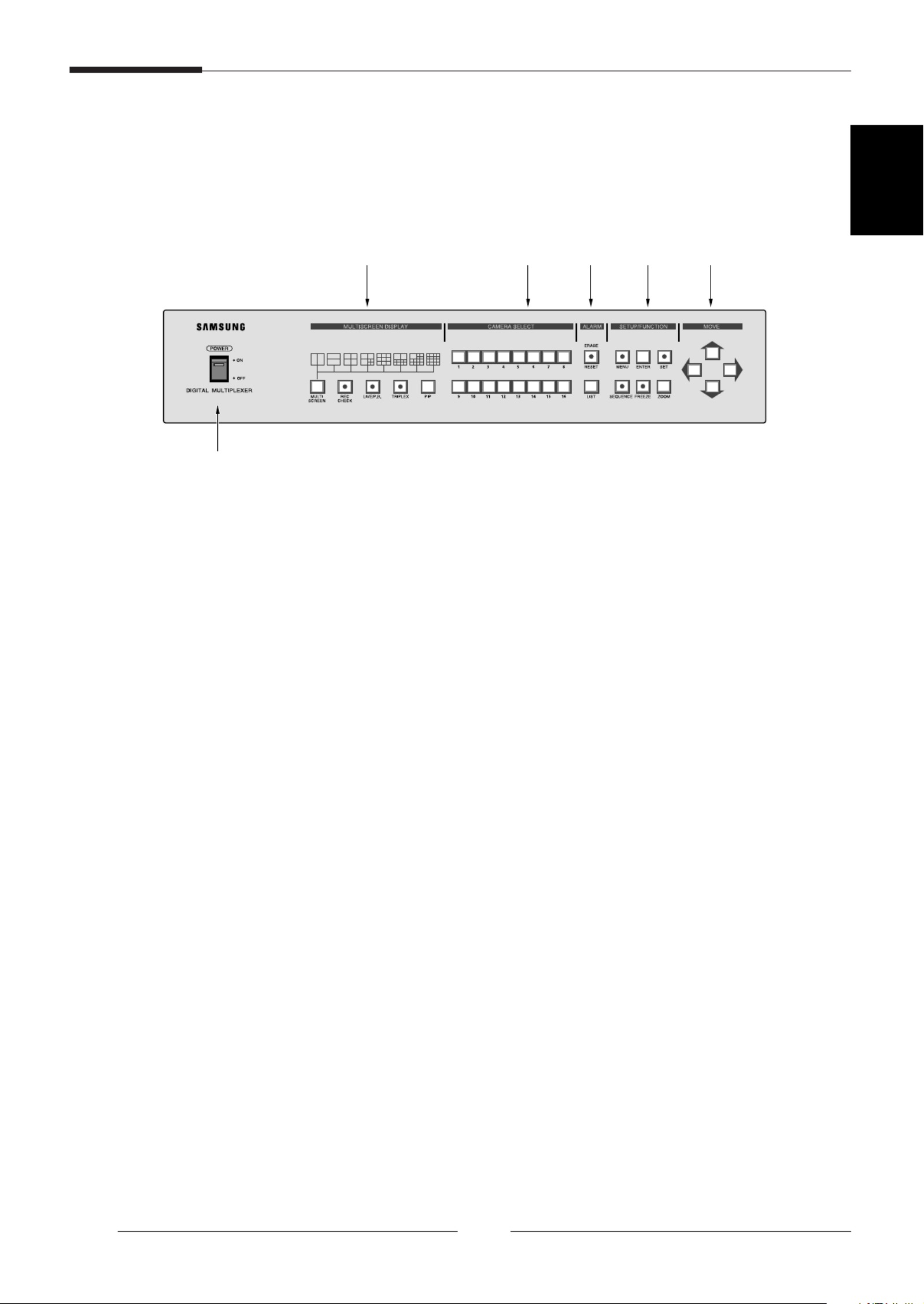
Name of parts and Function
FRONT PANEL
A. POWER SWITCH
Power ON/OFF.
B. MULTI SCREEN DISPLAY
- MULTI SCREEN
You are in the multi-screen mode. Each press of the MULTI SCREEN Button shows the picture
displayed.
- REC CHECK
LIVE MODE: VCR output is displayed on the monitor.
P.B MODE: VCR input is displayed on the monitor.
This mode flashes during REC CHECK operation.
- LIVE/P. B.
Button for selecting either LIVE MODE or Playback MODE. LIVE MODE will be flashed.
- TRIPLEX
Button for selecting TRIPLEX MODE. Flashes during TRIPLEX operation.
- PIP
Button for selecting PICTURE-IN-PICTURE.
C. CAMERA SELECT
Button for selecting proper CHANNEL.
D. ALARM
- RESET/ERASE
Button for deactivating ALARM. When ALARM is input, RESET/ERASE Button should illuminate.
When “ALARM/LOSS LIST” is displayed on the screen, pressing this Button will erase page by page.
- LIST
Shows ALARM/LOSS LIST.
Digital Multiplexer
1-2
ENGLISH
A
B C D E F

Digital Multiplexer
1-3
E. SETUP/FUNCTION
- MENU
Pressing this Button will make LED lit, and MAIN MENU appears on the screen.
- ENTER
Used when switching from MAIN MENU to SUB MENU.
- SET
This function is used when moving from SUB MENU to MAIN MENU after setting programs on
each MENU screen, or is used when setting each channel for multi-screen. When setting channels
for multi-screen, the channel number flashes.
- SEQUENCE
When pressing this Button, each Channel will automatically be switched to the next channel
sequentially with some time intervals, and LED should illuminate. Pressing again will stop
illuminating, and stops sequencing.
- FREEZE
When pressing this Button, selected screen becomes still, and LED should illuminate.
- ZOOM
When pressing this Button, the screen should enlarge. Pressing once enlarges twice, and another
pressing enlarges 4 times, and pressing once again will bring the screen back to normal.
F. MOVE ( , , , )
This function is used when setting Program Menu, Channel of Multi-screen, and Zoom Mode, and
also when moving Cursor.
→
→
→
→

Digital Multiplexer
2-1
CHAPTER 2. INSTALLATION
Preparing for the Installation
The following information is prepared for safe installation of the unit.
This unit can be placed on a flat table or installed in the rack. It should not be used vertically or skew, but
horizontally. The location of the unit and the composition of wiring are very important in properly operating
the system. When equipment is placed too close or if ventilation is not properly done, system may not
work properly, and maintenance of the system may be difficult. In order to prevent system failure and to
reduce system shut-down by outside environmental factors, air circulation in the system operating room,
and the cover of the unit must be fixed. Do not open the cover voluntarily because high voltage within the
unit may cause electric shock.
PHYSICAL & ENVIRONMENTAL
•Operating Temperature : 0 C to 40 ° °C
•Maintenance Temperature : -20 C to 60 ° °C
•Operating Humidity : 20% to 85% (RH)
•Maintenance Humidity : 20% to 95% (RH)
•Power Supply : 100 ~ 240 VAC
•Power Consumption : less than 14W
•Frequency : 50 / 60 Hz
CAUTIONS
When system is operated, input voltage range must be within 10% of nominal voltage, and power
consent should be grounded. Heating devices such as hair dryer, iron, refrigerator should not be used
together. For safe power supply, AVR (Automatic Voltage Regulator) is recommended.
The connector linked to this equipment can affect EMI, so it is recommended to coil the CORE-FERRITE
for use.

Precautions when Installing
Precautions when Installing
•Be sure to turn the unit off before installing.
•Avoid shock or vibration since
they may cause unit malfunction.
•Keep away from magnets, radio or TV to avoid
magnetic damage.
•During or after installing the unit, be sure to maintain the
area around the unit clean.
•Place the unit on a flat surface and maintain temperature
properly. Allow 15 cm of clearance between the rear
panel and the wall.
•Be careful not to drop any conductive materials into the
hole for ventilation
Digital Multiplexer
2-2
ENGLISH
15Cm

Digital Multiplexer
2-3
•When replacing built-in fuse, be sure to turn the power
off, and unplug the unit.
•Avoid locating the unit where direct sunlight will fall, and
maintain it cool. Keep tools and equipment away from
people so that they would not be hurt.
•Power Outlet should be grounded 2P(or 3P)Type.
•If ignoring smoke or smell while using the unit, fire or
electric shock may occur. In this case, turn the power
switch off immediately, and consult professionals in the
closest service center.
•Be sure to check dangers, which may occur due to
damped floor, ungrounded power extension cable, worn
power cord or lack of safety grounding.
CAUTIONS
When cleaning this unit, be sure to wipe with a dried cloth. If the unit is heavily contaminated, wipe it
with a soft cloth dampened with a mild detergent solution, then wipe dry with a soft clean cloth. Do not
use chemicals such as alcohol, benzene, or thinner because a chemical reaction could result permanent
damaging of the cabinet surface.

UNPACKING
Place shipping container on a flat surface, cut straps or tape, open top. Then, review the content;
the following items should be included:
•Main Unit
•User Manual (this document)
•One (1) Power Unit
•Two Rack Mount Adaptors
Digital Multiplexer
2-4
ENGLISH

Digital Multiplexer
3-1
CHAPTER 3. Connecting to Other Devices
This unit can be connected to other devices such as monitor, camera, VCR, and PC. This chapter
describes how to connect the unit to other devices.
CAUTIONS
Be sure that voltages higher than 2 VDC should not be input to the input terminal of Camera and Video.
1. Connecting to normal VCR and Monitor
When connecting to a normal VCR, Select ‘NOR’
in “REC TYPE” of 1. REC OUT SET“ ” in SETUP
MENU.
1. Connect a BNC cable to the VCR IN terminal
on the Unit Rear Panel and to the OUT
terminal of the VCR.
2. Connect a BNC cable to the VCR OUT
terminal on the Unit Rear Panel and to the IN
terminal of the VCR.
3. Connect a BNC cable to the MON OUT
terminal on the Unit Rear Panel and to the IN
terminal of the Monitor.
2. Connecting to S-VHS VCR and S-VHS MONITOR
When playing back TAPE by connecting to S-
VHS, select “Y/C” in PB IN Mode, once you“ ”
in “2.MON OUT SET” Mode in SETUP Menu.
1. Connect a S-JACK cable to the VCR IN 4-
pin terminal on the Unit’s Rear Panel and to
the OUT terminal on the VCR.
2. Connect a S-JACK cable to the VCR OUT
4-pin terminal on the Unit’s Rear Panel and
to the IN terminal on the VCR.
3. Connect a S-JACK cable to the MON OUT
4-pin terminal on the Unit’s Rear Panel and
to the IN terminal on the Monitor.
✴
SDM-160M/SDM-160MP:Not used.
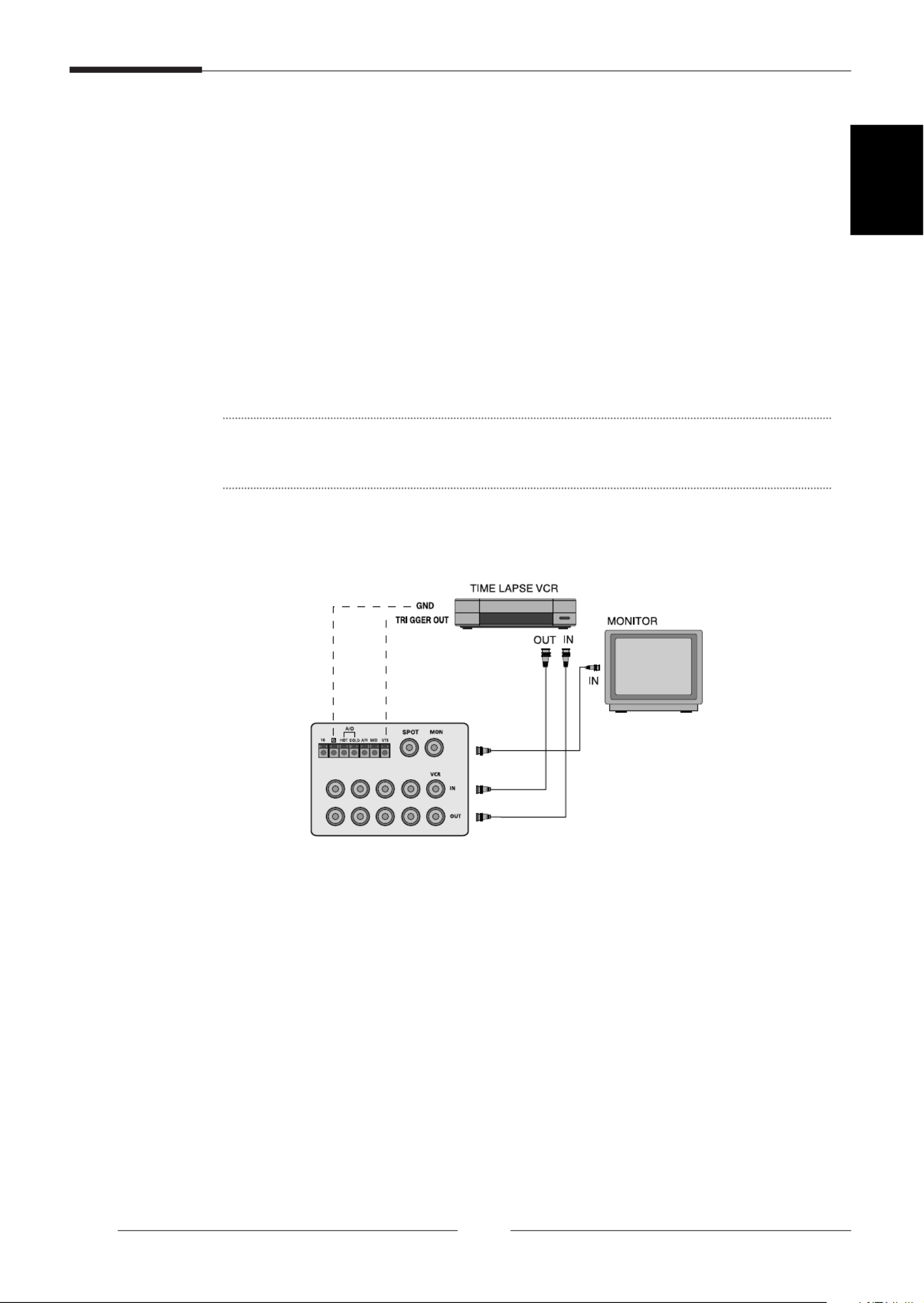
3. Connecting to TIME LAPSE VCR
When connecting the unit to the TIME LAPSE VCR, set “TLV” in “REC TYPE” after selecting “1.REC
OUT SET” of SETUP MENU.
1. Connect a S-JACK cable to the VTI terminal on the Unit’s Rear Panel and to the REC TRIG OUT
terminal on the VCR.
2. Connect a S-JACK cable to the ‘G’ ’terminal on the Unit s Rear Panel and to the ‘G’terminal on the
VCR.
3. Connect a cable to the VCR IN terminal on the Unit’s Rear Panel and to the VCR OUT terminal on
the VCR. Likewise, connect a cable to the VCR IN terminal on the Unit’s Rear Panel and to the VCR
OUT terminal on the VCR.
CAUTIONS
Depending on the kinds of TIME LAPSE VCR, the name of REC TRIGGER OUT terminal may be
different, so be sure to connect after checking its name.
Digital Multiplexer
3-2
ENGLISH

Digital Multiplexer
3-3
4. Connecting to ALARM SENSOR
1. Connect the ALARM terminal on the Unit’s Rear Panel to the SENSOR CORRESPONDING TO
camera number.
2. Connect grounding wires.
3. Connect the HOT terminal on the Unit’s Rear Panel to the ALARM IN terminal on the VCR.
4. Connect the COLD terminal on the Unit’s Rear Panel to the COM terminal on the VCR.
5. Connect the A/R terminal on the Unit’s Rear Panel to the RESET terminal on the VCR.
CAUTIONS
Depending on the kinds of TIME LAPSE VCR, the name of REC TRIGGER OUT terminal may be different,
so be sure to connect after checking its name.
ALARM Externa
Conecte a dispos

5. Remote Control by connecting to PC
A. Connecting to RS-232C
The unit can be remote-controlled by connecting to PC in which terminal emulation program is built.
At this time, RS-232C Cable is used for connection. When connecting to the PC by RS-232C,
some keys on the PC keyboard can be used as Function Buttons on the Unit’s Front Panel.
RS-232C Terminal(D-SUB 9PIN)
RS-232C 9PIN(Connector Allocation)
PIN NUMBER PIN SPECIFICATIONS
2 TXD(TRANSMITTED DATA)
3 RXD(RECEIVED DATA)
5 SG(SIGNALGROUND)
1, 4, 6 ~ 9 NO CONNECTION
ASCII Function ASCII Function
1 CH1 T TRIPLEX
2 CH2 P PIP
3 CH3 R RESET
4 CH4 L LIST
5 CH5 M MENU
6 CH6 A(AUTO) SEQUENCE
7 CH7 E ENTER
8 CH8 F FREEZE
9 CH9 S SET
a(HEX) CH10 Z ZOOM
b(HEX) CH11 h (MOVE )
c(HEX) CH12 i (MOVE )
d(HEX) CH13 j (MOVE )
e(HEX) CH14 k (MOVE )
f(HEX) CH15 l LEFT_UP
g(SEMI-HEX) CH16 m LEFT_DOWN
W(WINDOW) MULTI SCREEN n RIGHT_UP
C REC CHECK/PB o RIGHT_DOWN
THROUGH
V LIVE/PB
•
Transmission speed : Select from 4800,9600, 19200, 38400 bps
•
data bit : 8 bits
•
parity : none
•
stop bit : 1 bit
Digital Multiplexer
3-4
ENGLISH
1
5
69
→
→
→
→

6. Remote Control using SSC-1000(RS-485)
Refer to SSC-1000 manual
1. RS-485 Address set-up : Only odd numbers are available.(from 1 to 253)
2. Get into Control Mode by pressing MUX CONTROL“ ”(SSC-1000) button.
3. “MON” Address set-up(SSC-1000)
! MONITOR OUT CONTROL
RS-485 Address set-up value input.(“ ”MON button → Address input → ENTER)
@ SPOT OUT CONTROL
“ ”Address set-up value +1 input.
(“MON” button → “Address + 1” input → ENTER)
4. MONITOR OUT CONTROL
Refer to SSC-1000’s CONTROL PANEL
(One to one with front panel)
5. SPOT OUT CONTROL
- With select input channel. chcannel fixed output.
- With select “ ”HOLD(SEQUENCE) button, switching screen output.
(Switching output according to “SPOT OUT” set-up)
Digital Multiplexer
3-5

Digital Multiplexer
4-1
ENGLISH
Chapter 4. Basic Method to use
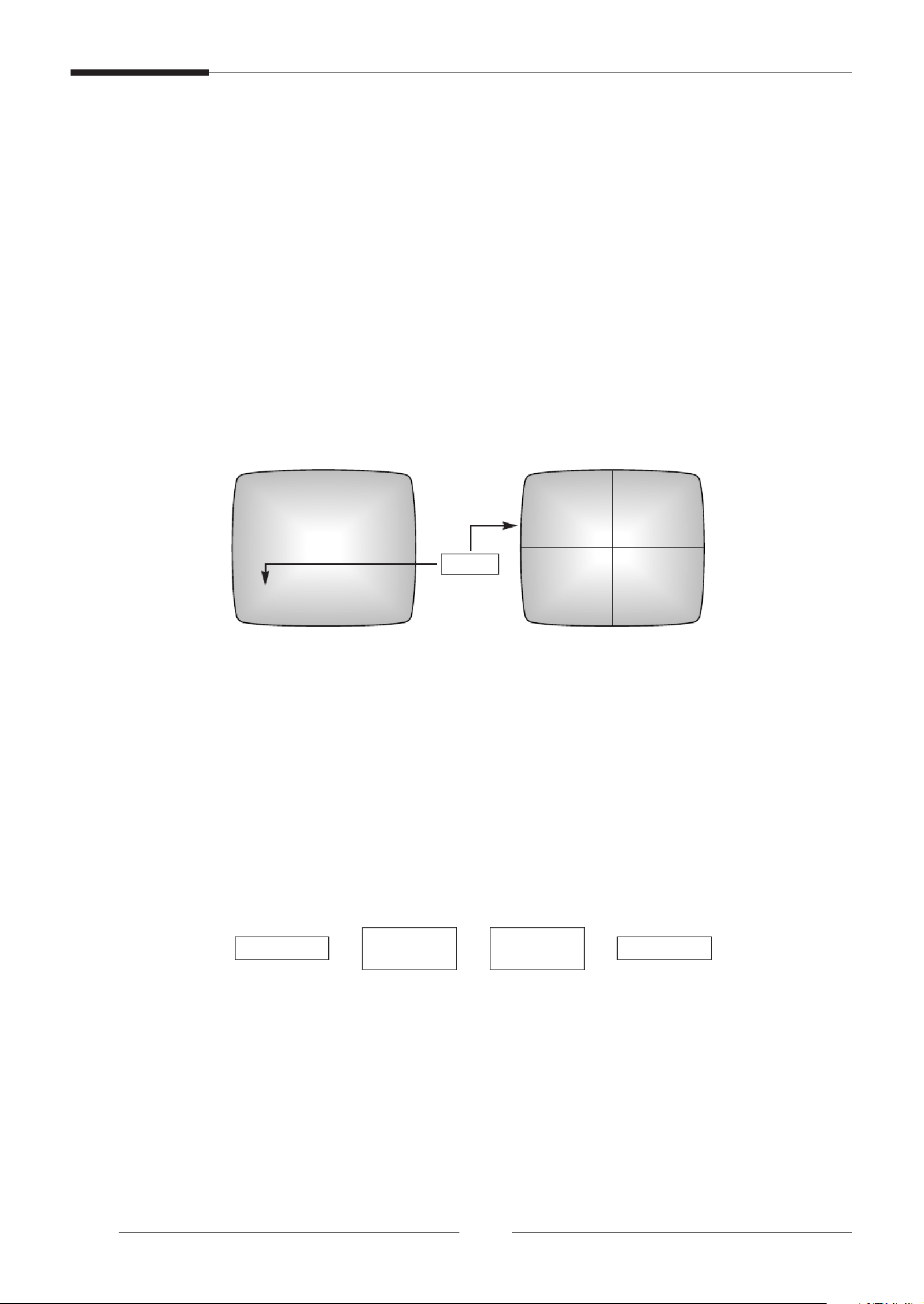
Initial operation
1. Turn on power switch.
A 4-division screen appears on the monitor if firstly operating after purchase. In this case, the channel
without inputting appears in the blue background on the screen and a video loss occurs.
(The current operation status is memorized when the power turns off after completing the initial
setting and thus the unit operates in the operation status when the power turns off if turning power
on.)
2. Setup a recording channel.
Set the channel without inputting to “off” in the “DUTY SET” of “1.REC OUT SET” on the program
menu.
3. Change it to a desiring indication mode.
- Indication of FULL screen: The selected channel is indicated on monitor in the form of FULL
channel.
- Indication of division screen: The division screen is indicated on monitor if pressing the multi-
screen button. Resetting channel is available for the division screen if user wants.
- Indication of automatic sequential conversion: The full screen is automatically converted if
pressing the sequence button.
- Indication of stop screen: A desired channel can be seen in a form of stop screen using the
freezing button and camera selection button.
- Indication of live/P.B: The current camera signal may be monitored or the recorded screen may be
reproduced for a view using the live/P.B button.
- Indication of TRIPLEX screen: The current camera signal and the recorded screen may be seen
on the same monitor using the TRIPLEX button.
- Indication of PIP screen: The PIP (picture in picture) screen may be seen using the PIP button.
- Indication of expansion screen: The full screen may be expanded up to 4 times for view using the
zoom and move button.
- Indication of record check screen: The recorded output screen or the output screen of VCR may
be seen using the REC CHECK button.
When desiring to see in the live screen/replay screen
The live/P.B“ ” select button determines the live screen/replay screen mode.
The LED turns on in the live mode and it turns off in the tape replay mode.
If pressing this button, the indication mode is changed to the replay mode for the live mode and to the
live mode for the replay mode.
➢The LIVE/P.B“ ” button does not operate in the following cases:
- During zoom operation
- In setting of program mode
- In displaying ALARM/LOSS LIST on screen
When desiring to see in the TRIPLEX screen
The TRIPLEX“ ” button sets the TRIPLEX screen mode. In this case the LED turns on and the previous
TRIPLEX division mode is set.
➢The TRIPLEX“ ” button does not operate in the following cases:
- During zoom operation
- In setting of program mode
- In displaying ALARM/LOSS LIST on screen

Digital Multiplexer
4-3
ENGLISH
When desiring to see automatic sequential conversion screen
The automatic sequential conversion mode operates in the LIVE screen status and consists of the
following 2 cases:
The FULL screen is converted if pressing the “SEQUENCE” button in the FULL screen status. The
screen on the bottom right side is converted if pressing the “SEQUENCE” button in the 4, 9-division
screen status. The LED of the “SEQUENCE” button turns on for both cases.
The conversion time in the automatic sequential conversion mode is set in the “SEQUENCE..” of the
“ ”2. MON OUT SET in case of the PRPGRAM mode for the FULL screen and the time to set up is
00sec ~ 30sec. The screen set to 00sec is skipped. The screen on the right bottom is switched in the
interval of a second for the 4, 9-division screen.
➢Method to release
- Press the “SEQUENCE” button once again. In this case the LED turns off. And then it stops on
the screen currently seen.
➢The SEQUENCE“ ” button does not operate in the following cases:
- In replay mode or TRIPLEX mode
- In the division screen mode other than 4, 9-division screen
- In setting of program mode
- In displaying ALARM/LOSS LIST on screen
- During ZOOM operation
- During ALARM operation
Digital Multiplexer
4-4
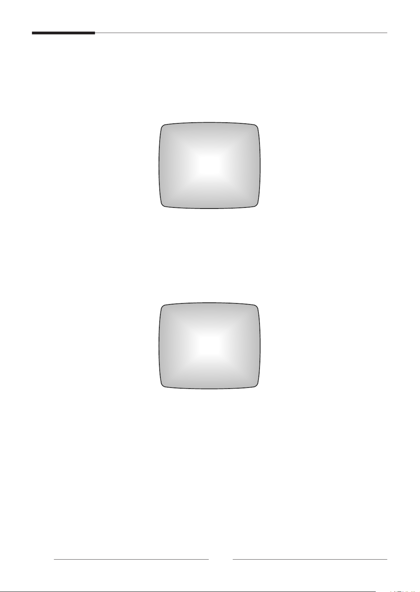
When desiring to see the stop screen
The monitor screen (full screen and division) may be seen with a temporary stop.
A desired screen may be temporarily stopped selectively in the division screen indication mode.
1. FREEZE setting of FULL screen
The LED turns on and monitor image stops and “FREEZE” character is indicated on the screen if
pressing the “FREEZE” button in the FULL screen mode. The LED turns off and the stop mode is
released if pressing the “FREEZE” button once again.
2. FREEZE setting of division screen
The LED blinks if pressing the “FREEZE” button. The selected screen stops if selecting a channel
to freeze, and “F” character is displayed. The selected channel is released if pressing the relevant
channel again and stop of all channels if pressing the “FREEZE” button.
➢The FREEZE“ ” button does not operate in the following cases:
- In setting division screen mode
- In setting of program mode
- In displaying ALARM/LOSS LIST on screen
When desiring to see in the zoom screen
The zoom screen operates if pressing “ZOOM” button in the FULL mode. The mode is changed in
the following order whenever pressing this button.
Select the area to expand using the “MOVE” ( , , , ) button.
Moving to the diagonal direction is allowed using the double button (right upper, left below, right upper, right
below).
➢The ZOOM“ ” button does not operate in the following cases:
- In division screen mode
- In setting division screen
- In setting of program mode
- In displaying ALARM/LOSS LIST on screen
01/05/01 12:30:26 01/05/01 12:30:26
CH1
FULL screen 4-division screen
Flash
CH1
F
F
CH2
CH3 CH4
FREEZE
FULL MODE 2TIMES
ZOOM
4 TIMES
ZOOM FULL MODE
➞ ➞➞
→
→
→
→

Digital Multiplexer
4-5
ENGLISH
When desiring to see in the PIP screen
The PIP (picture in picture) screen may be seen using the “PIP” button on the FULL screen in the LIVE
mode. The size of the PIP sub-screen is set in the of the 2. MON OUT SET on the“PIP SIZE” “ ”
program menu. The sub-screen is automatically and sequentially converted if pressing the
“ ”SEQUENCE button.
➢Method to use
1. Press the “PIP” button.
2. Press the “SET”. In this case the LED of the “SET” button blinks and the border line blinks.
Then, set the sub-screen of the PIP screen to a desired channel.
3. Press the “SET” button if completing the channel setting. In this case the LED of the “SET”
button turns off.
4. Fix the position of the sub-screen using the “MOVE” button. The position of the sub-screen may
be selected in 4 cases of right upper, left below, right upper, right below.
➢The PIP“ ” button does not operate in the following cases:
- In replay mode or TRIPLEX mode
- In division screen
- In automatic sequential conversion mode
- In zoom operation
- In setting program mode
- In displaying ALARM/LOSS LIST on screen
When desiring to see in the record screen
You can see the record output screen in the live mode using the “REC CHECK”.
When desiring to see output of VCR as it is
You can see the output screen of VCR using the “REC CHECK” button in the replay mode. This mode is
useful when adjusting MENU of VCR.
➢The “REC CHECK ” button does not operate in the following cases:
- In zoom operation
- In setting program mode
- In displaying ALARM/LOSS LIST on screen
Digital Multiplexer
5-1
Chapter 5. Setting of Program Menu
<MAIN MENU>
The following main menu is displayed on the monitor screen if pressing “MENU” button, the “MENU” LED turns
on. The LED turns off if pressing the button and it returns to the previous status.
< SUB MENU>
- Select item 1~7 of the main menu using the “MOVE” button ( , ).
- Press the “ENTER” button to move to the sub-menu.
1. Record setting of each camera
You can set record mode and record duty, ON/OFF, reservation of each channel. The following screen is displayed
on screen if pressing the “ENTER” button after placing the blinking indication on the 1. REC OUT SET“ ” by pressing
the “MOVE” button from the main menu.
- The blinking indication moves if pressing “ ”, “ ” button.
- The setting value is changed if pressing “ ”, “ ” button.
- The changed setting value is stored if pressing the “SET” button. You can return to the main menu.
REC TYPE : NOR ↔ TLV
•
NOR : Used when connecting general VCR. Output is done in Field or Frame.
•
TLV : Used when recording in the TLV mode by connecting the time lapse VCR.
- Output in the normal mode if no trigger signal exists though the setting is done in the TLV mode.
REC OUT : FIELD FRAME : Effective menu if ↔ “REC TYPE” is “NOR”.
•
FIELD : Output in 1/60 second (NTSC), 1/50 second (PAL)
•
FRAME: Output in 1/30 second (NTSC), 1/25 second (PAL)
- Reservation : ON ↔ OFF
[SETUP MENU]
1. REC OUT SET
2. MON OUT SET
3. CHANNEL TITLE SET
4. DATE / TIME SET
5. ALARM SET
6. MOTION SET
7. SYSTEM SET
[REC OUT SET]
REC TYPE TLV
REC OUT FIELD
DUTY SET...
RESERVATION OFF
→
→
→
→
→
→

Digital Multiplexer
5-2
ENGLISH
- The following screen is displayed if pressing the “ENTER” button with the blinking position placed at the “DUTY
SET ….”.
•
The blinking indication moves if pressing “ ” , “ ” button.
•
The setting value is changed if pressing “ ” , “ ” button:OFF,1~5.
•
The relevant channel is not recorded if the setting value is “OFF”.
•
The changed setting value is stored if pressing the “SET” button. You can return to the main menu.
- The following screen is displayed if pressing the “ENTER” button where the blinking position is at the“ON…”
“RESERVATION … ”. .
•
Useful menu when desiring to record only specific channels at a specific time.
•
Record the channels set from the start time to the end time.
•
The blinking indication moves if pressing “ ” , “ ” button.
•
The setting value is changed if pressing “ ” , “ ” button.
Start time, end time HH : 00 ~ 23
Start time, end time MM : 00 ~ 59
CH1 ~ CH16 : OFF ↔ ↔ ↔ ↔ ↔ ↔1 2 3 4 5 OFF
•
Channels set to “OFF” does not perform when carrying out reservation record.
•
The changed setting value is stored if pressing the “SET” button. You can return to the REC OUT SET“ ” menu.
[REC DUTY SET]
CH1 : 1 CH2 : 1
CH3 : 1 CH4 : 1
CH5 : 1 CH6 : 1
CH7 : 1 CH8 : 1
CH9 : 1 CH10 : 1
CH11: 1 CH12 : 1
CH13: 1 CH14 : 1
CH15: 1 CH16 : 1
[REC RESERVATION]
START TIME 00:01[HH:MM]
END TIME 23:59[HH:MM]
CH1 : 1 CH2 : 1
CH3 : 1 CH4 : 1
CH5 : 1 CH6 : 1
CH7 : 1 CH8 : 1
CH9 : 1 CH10: 1
CH11: 1 CH12: 1
CH13: 1 CH14: 1
CH15: 1 CH16: 1
→
→
→
→
→
→
→
→

Digital Multiplexer
5-3
2. Setting of display mode
You can set LIVE/PB display type, PIP size, sequence, and border color, PB IN, etc..
The following screen is displayed if pressing the “ENTER” button with the blinking position placed at the
“ ” “2. MON OUT SET by pressing MOVE” button on the main menu.
- The blinking indication moves if pressing “ ” , “ ” button.
- The setting value is changed if pressing “ ” , “ ” button.
LIVE DISPLAY: ALL ↔ TITLE ↔ DATE/TIME ↔ NONE ALL↔
PB DISPLAY : ALL ↔ TITLE ↔ DATE/TIME ↔ NONE ALL↔
•
ALL: Both date/time and title are displayed.
•
TITLE: Only channel title is displayed.
•
DATE/TIME : Only date/time is displayed.
•
NONE: Both date/time and title are not displayed.
PB IN: CVBS ↔ Y/C
•
Set the replay (P, B mode) input.
•
Y/C: Input of SUPER VHS
•
CBVS:COMPOSITE BNC input
•
SDM-160M/SDM-160MP:Not used.
PIP SIZE: 1/9 ↔ 1/16
•
Set the size of the sub-screen in the PIP mode.
BORDER COLOR: WHITE ↔ GRAY
•
Set color of the division line of the division screen or the PIP screen.
•
SDM-160M/SDM-160MP:Not used.
LOSS INFO: ON ↔ OFF
•
Set in order to advise LOSS information to the screen.
ALARM INFO: ON ↔ OFF
•
Set in order to advise ALARM information to the screen.
MOTION INFO: ON ↔ OFF
•
Set in order to advise MOTION information to the screen.
[MON OUT SET]
LIVE DISPLAY ALL
PB DISPLAY ALL
SPOT OUT...
PB IN CVBS
PIP SIZE 1/9
BORDER COLOR WHITE
SEQUENCE...
LOSS DETECT...
LOSS INFO ON
ALARM INFO ON
MOTION INFO ON
→
→
→
→

Digital Multiplexer
5-4
ENGLISH
- The following is displayed if pressing the “ENTER” button with the blinking position placed at the “SPOT OUT...”:
•
You can set the sequence time of SPOT output.
•
The blinking indication moves if pressing “ ” , “ ” button.
•
The setting value is changed if pressing “ ” , “ ” button.
CH1~CH16 : 0 to 30 seconds.
Alarm S/W TIME : 01 to 30 seconds.
•
The changed setting value is stored if pressing the “SET” button and you can return to the MON OUT SET menu.“ ”
✴
The channel of LOSS or 0 “ ” of sequence time will be skipped in the SPOT output sequence.
✴
SPOT OUTPUT on alarm
When the alarm is activated, only the alarmed channel will be output.
On single alarm : output only the alarmed channel.
On multiple alarms : output alarmed channels in turn at intervals of set ALARM S/W TIME.
(Even the sequence time of the alarmed channel is set as 0 “ ” then will be SPOT output.)
- The following is displayed if pressing the “ENTENR” button with the blinking position placed at “SEQUENCE….”:
•
Set the indication time (second) of each channel in the automatic conversion mode.
•
The blinking indication moves if pressing “ ” , “ ” button.
•
The setting value is changed if pressing “ ” , “ ” button.
CH1 ~ CH16 : 0 ~ 30
“0” is skipped irrespective of existence of channel loss in the automatic conversion mode.
•
The changed setting value is stored if pressing the “SET” button and you can return to the MON OUT SET menu. “ ”
[SEQUENCE]
CH1 : 02 CH2 : 02
CH3 : 02 CH4 : 02
CH5 : 02 CH6 : 02
CH7 : 02 CH8 : 02
CH9 : 02 CH10: 02
CH11: 02 CH12: 02
CH13: 02 CH14: 02
CH15: 02 CH16: 02
→
→
→
→
→
→
→
→
[SPOT OUT]
CH1 : 02 CH2 : 00
CH3 : 00 CH4 : 00
CH5 : 00 CH6 : 00
CH7 : 00 CH8 : 00
CH9 : 00 CH10 : 00
CH11 : 00 CH12 : 00
CH13 : 00 CH14 : 00
CH15 : 00 CH16 : 00
ALARM S/W TIME : 02

Digital Multiplexer
5-5
- The following screen is displayed if pressing the “ENTER” button with the blinking position placed at the “LOSS
DETECT….”:
•
Set whether LOSS DETECT by channel will be done.
•
The blinking indication moves if pressing “ ” , “ ” button.
•
The setting value is changed if pressing “ ” , “ ” button. : ON ↔ OFF
•
The changed setting value is stored if pressing the “SET” button and you can return to the MON OUT SET menu. “ ”
3.Setting of title by channel
- You can set of each channel.
- The following screen is displayed if pressing the “ENTER” button with the blinking indication placed the “3.
CHANNEL TITLE SET by pressing the ” “MOVE” button on the main menu screen:
- The blinking character moves if pressing “ ”, “ ” button.
- The background screen is changed to the relevant channel and the following screen is displayed if pressing the
“ ”ENTER button at a position desired to set title:
→
→
→
→
→
→
[CHANNEL TITLE SET]
CH1:--- CH1---- CH2:--- CH2----
CH3:--- CH3---- CH4:--- CH4----
CH5:--- CH5---- CH6:--- CH6----
CH7:--- CH7---- CH8:--- CH8----
CH9:--- CH9---- CH10:---CH10---
CH11:--- CH11--- CH12:---CH12---
CH13:--- CH13--- CH14:---CH14---
CH15:--- CH15--- CH16:---CH16---
[LOSS DETECT]
CH1 : ON CH2 : ON
CH3 : ON CH4 : ON
CH5 : ON CH6 : ON
CH7 : ON CH8 : ON
CH9 : ON CH10: ON
CH11: ON CH12: ON
CH13: ON CH14: ON
CH15: ON CH16: ON
Specyfikacje produktu
| Marka: | Samsung |
| Kategoria: | soundbar |
| Model: | SDM-160MP |
Potrzebujesz pomocy?
Jeśli potrzebujesz pomocy z Samsung SDM-160MP, zadaj pytanie poniżej, a inni użytkownicy Ci odpowiedzą
Instrukcje soundbar Samsung

15 Stycznia 2025
9 Października 2024
8 Października 2024
8 Października 2024
8 Października 2024
8 Października 2024
8 Października 2024
6 Października 2024
5 Października 2024
5 Października 2024
Instrukcje soundbar
- soundbar Sony
- soundbar Yamaha
- soundbar Sven
- soundbar LG
- soundbar Sharp
- soundbar TCL
- soundbar Philips
- soundbar Livoo
- soundbar SilverCrest
- soundbar JBL
- soundbar Onkyo
- soundbar Kärcher
- soundbar Bose
- soundbar Hisense
- soundbar Infiniton
- soundbar Panasonic
- soundbar Klipsch
- soundbar Muse
- soundbar Crestron
- soundbar Nedis
- soundbar Medion
- soundbar Boss
- soundbar OK
- soundbar Lenco
- soundbar Yealink
- soundbar ILive
- soundbar Blaupunkt
- soundbar Martin Logan
- soundbar Grundig
- soundbar Haier
- soundbar HP
- soundbar BTicino
- soundbar Creative
- soundbar Denon
- soundbar Audac
- soundbar Cambridge
- soundbar Edifier
- soundbar Polk
- soundbar Paradigm
- soundbar Bang & Olufsen
- soundbar JVC
- soundbar Trust
- soundbar Memphis Audio
- soundbar Dell
- soundbar Furrion
- soundbar Jamo
- soundbar Auna
- soundbar Schneider
- soundbar Krüger&Matz
- soundbar Renkforce
- soundbar Thomson
- soundbar Wharfedale
- soundbar Magnat
- soundbar Pyle
- soundbar ELAC
- soundbar NGS
- soundbar Sennheiser
- soundbar Peerless-AV
- soundbar Bowers & Wilkins
- soundbar Monitor Audio
- soundbar Fosi Audio
- soundbar Nevir
- soundbar Razer
- soundbar Continental Edison
- soundbar Harman Kardon
- soundbar GoGen
- soundbar NEC
- soundbar Aiwa
- soundbar AKAI
- soundbar Majority
- soundbar Teufel
- soundbar Dali
- soundbar Vision
- soundbar Kicker
- soundbar Hama
- soundbar Bush
- soundbar Bluesound
- soundbar Insignia
- soundbar Element
- soundbar Mac Audio
- soundbar Denver
- soundbar Trevi
- soundbar Technaxx
- soundbar Klip Xtreme
- soundbar GPX
- soundbar Definitive Technology
- soundbar PowerBass
- soundbar Canton
- soundbar Laser
- soundbar Adj
- soundbar Reflexion
- soundbar Megasat
- soundbar AMX
- soundbar Sonance
- soundbar Altec Lansing
- soundbar Devialet
- soundbar Cabasse
- soundbar Reflecta
- soundbar Proscan
- soundbar Energy Sistem
- soundbar Sonos
- soundbar Sylvania
- soundbar Steren
- soundbar Kubo
- soundbar Bigben Interactive
- soundbar AV:link
- soundbar MB Quart
- soundbar Bigben
- soundbar Naxa
- soundbar Sherwood
- soundbar Fantec
- soundbar Konig
- soundbar Boston Acoustics
- soundbar Ices
- soundbar Vizio
- soundbar Pure Acoustics
- soundbar Ematic
- soundbar BlueAnt
- soundbar Integra
- soundbar Russound
- soundbar Bazooka
- soundbar Avtex
- soundbar Monoprice
- soundbar Aconatic
- soundbar Voxicon
- soundbar Neets
- soundbar Xoro
- soundbar PSB
- soundbar Maxell
- soundbar Orbitsound
- soundbar Wet Sounds
- soundbar Legamaster
- soundbar Q Acoustics
- soundbar Logic3
- soundbar GOgroove
- soundbar Kogan
- soundbar EKO
- soundbar Roku
- soundbar Mtx Audio
- soundbar GoldenEar Technology
- soundbar MusicMan
- soundbar Selfsat
- soundbar FALLER
- soundbar Astell&Kern
- soundbar Magnavox
- soundbar Vifa
- soundbar Thonet & Vander
- soundbar Planet Audio
- soundbar Energy
- soundbar SunBriteTV
- soundbar SoundTube
- soundbar Edis
- soundbar Séura
- soundbar Phase Technology
Najnowsze instrukcje dla soundbar

9 Kwietnia 2025
3 Kwietnia 2025

31 Marca 2025
30 Marca 2025
26 Marca 2025

12 Marca 2025
10 Marca 2025
5 Marca 2025
27 Lutego 2025

26 Lutego 2025