Instrukcja obsługi PreSonus StudioLive 16.0.2 USB
PreSonus
Konsola miksująca
StudioLive 16.0.2 USB
Przeczytaj poniżej 📖 instrukcję obsługi w języku polskim dla PreSonus StudioLive 16.0.2 USB (78 stron) w kategorii Konsola miksująca. Ta instrukcja była pomocna dla 5 osób i została oceniona przez 2 użytkowników na średnio 4.5 gwiazdek
Strona 1/78

StudioLive™ 16.0.2 USB
Performance and Recording Digital Mixer
Owner’s Manual
www.presonus.com
®
English

Table of Contents
1 Overview — 1
1.1 Introduction — 1
1.2 About This Manual — 2
1.3 Summary of StudioLive 16.0.2 Hardware
Features — 2
1.4 What is in the Box — 3
1.5 What is in Your My PreSonus account — 3
2 Getting Started — 4
2.1 Level Setting Procedure — 4
3 Hookup — 7
3.1 Rear-Panel Connections — 7
3.2 Typical Basic Band Hookup Diagram — 10
3.3 Business Conference Hookup Diagram — 11
4 The Fat Channel — 12
4.1 The Select Button — 12
4.2 Input Controls — 13
4.3 Dynamics Processing and EQ — 14
4.3.1 Fat Channel Processing Guide — 14
4.3.2 High Pass Filter — 15
4.3.3 Gate — 15
4.3.4 Compressor and Limiter — 16
4.3.5 Equalizer — 18
4.3.6 Dig Out: Recording EQ and
Dynamics — 20
4.4 Fat Channel Presets: Copy, Paste, Load — 21
4.4.1 Copying and Pasting — 21
4.4.2 Loading Fat Channel Presets — 22
4.4.3 Saving Fat Channel Presets — 23
4.4.4 Channel Presets Library — 24
4.5 Metering — 25
4.5.1 StudioLive Metering Controls — 25
5 Basic Controls — 26
5.1 Input Channel Controls — 26
5.2 Aux and FX Buses — 27
5.2.1 Analog Aux Bus Controls — 27
5.2.2 Internal FX Bus Controls — 28
5.2.3 Aux and FX Bus Channel Sends — 28
5.2.4 Creating Monitor Mixes — 29
5.2.5 Creating Internal FX Mixes — 30
5.3 MultiModes — 31
5.3.1 USB Return Mode. — 31
5.3.2 Solo Mode — 31
5.3.3 Mute Button — 32
5.4 Main Output Bus — 32
5.5 Talkback System — 32
5.6 Solo Bus — 33
5.6.1 Using the Solo Bus for Monitoring — 34
5.6.2 Using Solo in Place (SIP)
to Set Up a Mix — 35
5.7 Monitor Bus — 36
6 Digital Effects | Master
Control — 38
6.1 The Digital FX (Effects) Menu — 38
6.1.1 Creating FX Presets — 39
6.1.2 Reverb and its Parameters — 40
6.1.3 Delay and its Parameters — 41
6.1.4 Digital Effects Preset Library — 42
6.1.5 Digital Effects Types — 43
6.2 Scenes — 44
6.2.1 S1: Zero Out (Board Reset) — 44
6.2.2 Creating a Scene — 44
6.2.3 Scene Recall — 45
6.2.4 Fader Locate — 47
6.2.5 AutoStore — 47

6.3 Graphic Equalizer — 47
6.3.1 The Graphic EQ Menu and Controls — 49
6.3.2 Saving and Loading GEQ Presets — 50
6.4 System Menu — 51
6.4.1 LCD Contrast and LCD Backlight — 51
6.4.2 Aux Send Position — 52
6.4.3 MIDI Control Mode — 52
6.4.4 Lockout Mode — 53
6.4.5 Firmware Version — 53
6.5 Using MIDI Control Mode
to Remote-Control StudioLive — 53
6.5.1 Understanding MIDI — 54
6.5.2 Recalling Scenes
and FX Presets Remotely — 54
6.5.3 Using Control Change Messages to Control
Volume and FX Assignments — 54
6.5.4 Controlling the StudioLive 16.0.2
with a Behringer FCB1010 — 55
6.5.5 Controlling the StudioLive 16.0.2
with a Roland FC-300 — 58
7 Resources — 62
7.1 Stereo Microphone Placement — 62
7.2 EQ Frequency Guides — 65
7.3 Technical Specifications — 67
7.4 StudioLive 16.0.2 Block Diagram — 69
7.5 StudioLive 16.0.2 Recall Sheet — 70
8 Troubleshooting — 71
8.1 Troubleshooting — 71


1
1 Overview
1.1 Introduction
StudioLive™ 16.0.2 USB
Owner’s Manual
1 Overview
1.1 Introduction
Thank you for purchasing the PreSonus StudioLive™ 16.0.2 USB Performance and
Recording Digital Mixer. PreSonus Audio Electronics has designed the StudioLive
utilizing high-grade components to ensure optimum performance that will last a
lifetime. Loaded with 12 high-headroom, XMAX™ microphone preamplifiers; a built-
in 18x16 USB 2.0 recording and playback engine; MIDI I/O; Fat Channel processing
with 3-band semi-parametric EQs, compressors, limiters, and downward expanders;
reverb and delay effects; 4 aux buses; extensive LED metering; mixer save/recall;
channel-strip save/recall/copy/paste; talkback; and more, StudioLive breaks new
boundaries for music performance and production. All you need is a computer
with a USB 2.0 connection, a few microphones and cables, speakers, and your
instruments, and you are ready to record in the studio or in front of a live audience!
We encourage you to contact us with questions or comments regarding
this product. PreSonus Audio Electronics is committed to constant
product improvement, and we value your suggestions highly. We believe
the best way to achieve our goal of constant product improvement is by
listening to the real experts: our valued customers. We appreciate the
support you have shown us through the purchase of this product.
For technical support, please see Section 8.1: Troubleshooting.

2
1 Overview
1.2 About This Manual
StudioLive™ 16.0.2 USB
Owner’s Manual
1.2 About This Manual
We suggest that you use this manual to familiarize yourself with the features,
applications, and connection procedures for your StudioLive before trying
to connect it to your computer. This will help you avoid problems during
installation and setup. This manual covers hardware functions for the StudioLive
16.0.2 USB. A separate manual, covers the StudioLive 16.0.2 USB Software
Library as well as connecting and using your StudioLive with a computer.
Throughout this manual you will find Power User Tips. These tips provide mix
tricks that are unique to the StudioLive as well as explanations for various
audio terms. In addition to the Power User Tips, you will find an assortment
of audio tutorials at the back of this manual. These tutorials cover everything
from microphone placement to equalizer and compression-setting suggestions
and are included to help you get the most from your StudioLive mixer.
Thank you, once again, for buying our product. We are
confident that you will enjoy your StudioLive!
1.3 Summary of StudioLive 16.0.2 Hardware Features
424-bit/48 kHz sampling rate
4
12 Class A XMAX microphone preamplifiers
416 line-level inputs
44 auxiliary buses
4
High-definition analog-to-digital converters (118 dB dynamic range)
4
Unlimited-headroom, 32-bit floating-point, digital mixing and effects processing
4
18x16 USB 2.0 digital recording interface
4
Scene automation with load/save/recall of all settings
4Fat Channel with:
9High-pass filter
9Compressor
9Limiter
9
Downward expander
93-band semi-parametric EQ
9
Pan, phantom power, polarity invert, load/save presets
4
Master effects processors (reverb and delay with Load and Save)
4
MIDI control over: Scene and FX Recall, FX to Main
assign, Main Output, and FX Return Level
460 mm faders
4Military-grade quick-touch buttons
4
Fast-acting LED meters
4
Talkback communication system
4Rugged steel chassis
4
Compatible with Cubase, Digital Performer, Logic,
Nuendo, Sonar, Studio One®, and others
4
Windows® and Mac® compatible

3
1 Overview
1.4 What is in the Box
StudioLive™ 16.0.2 USB
Owner’s Manual
Powerful StudioLive software library includes:
4
UC Surface advanced remote control app for
macOS®, Windows®, iPad®, and Android™
4
QMix™-UC remote aux-mix app for iPhone®/
iPod touch® (free from Apple App Store)
4
Capture™ integrated multitrack-recording software
4Studio One® Artist digital audio workstation with more
than 6 GB of plug-ins, loops, and sounds
1.4 What is in the Box
Your StudioLive package contains the following:
4
PreSonus StudioLive 16.0.2 USB digital recording and performance mixer
41.5-foot (0.5m) USB cable
4IEC power cord
4
PreSonus Health Safety and Compliance Guide
1.5 What is in Your My PreSonus account
4
StudioLive 16.0.2 USB Hardware Manual
4StudioLive 16.0.2 USB Software Reference Manual
4
PreSonus Studio One Artist application and content
4PreSonus Capture
4
PreSonus Universal Control
Power User Tip: All companion software and drivers for your PreSonus StudioLive 16.0.2
USB mixer are available for download from your My PreSonus user account. Please visit
http://my.presonus.com and register your StudioLive 16.0.2 USB mixer to receive
downloads and licenses.
4
2 Getting Started
2.1 Level Setting Procedure
StudioLive™ 16.0.2 USB
Owner’s Manual
2 Getting Started
Before you begin, here are a few general rules of thumb:
4Always turn down the Main fader and both the Monitor and Phones
knobs in the Monitor section down before making connections.
4
Before plugging or unplugging a microphone while other channels
are active, mute the channel to which you are connecting.
4
Your faders should be set on or near the “U” mark whenever possible.
The “U” indicates unity gain, meaning the signal is neither boosted
nor attenuated. If the main output of your StudioLive is too high or
too low when your faders are at or near unity, you can use the main
output-level knob on the rear panel of the StudioLive to adjust the
level up or down until you have achieved the optimal volume.
4
Do not allow your inputs to clip. Watch the level meters; when the LEDs near
the Clip mark, the top LED will illuminate, indicating that the analog-to-digital
converters are in danger of being overdriven. Overdriving the converters
will cause digital distortion, which sounds terrible. The XMAX™ preamps
in your StudioLive provide plenty of headroom; take advantage of it.
Your P.A. and studio equipment should be powered on in the following order:
4
Sound sources (keyboards, direct boxes, microphones,
etc.) connected to the StudioLive inputs
4StudioLive mixer
4Computer (if applicable)
4
Power amplifiers or powered monitors
When it’s time to power down, your system should be turned off in the reverse
order. Now that you know what not to do, let’s get some audio going!
2.1 Level Setting Procedure
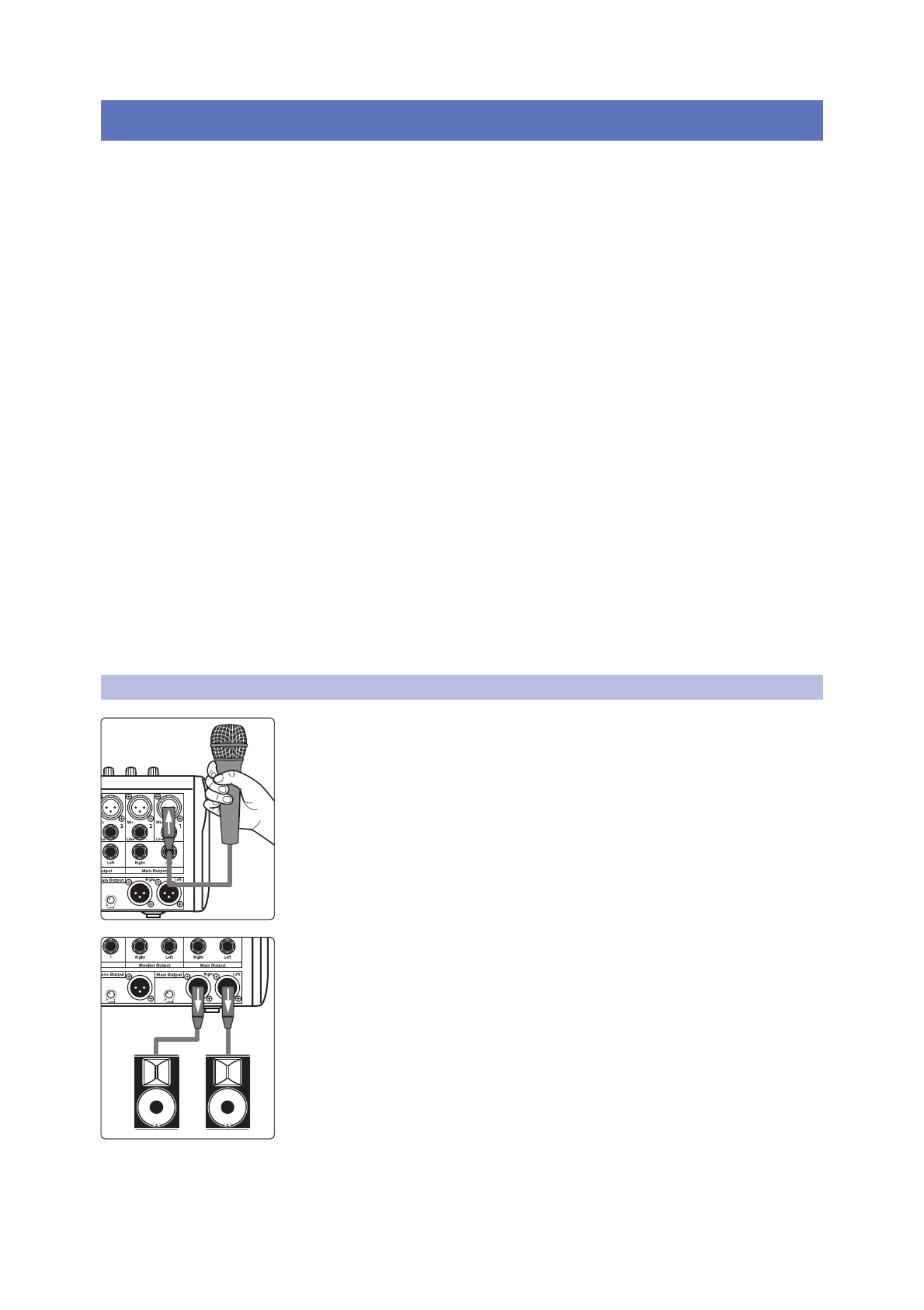
1. Grab a microphone and a mic cable and plug them into the StudioLive’s
Channel 1 mic input.
2. Connect the Main outs (TRS or XLR) of your StudioLive to your power amplifier
or powered monitors. If you’re using passive speakers, connect them to your
power amplifier using speaker cable.

5
2 Getting Started
2.1 Level Setting Procedure
StudioLive™ 16.0.2 USB
Owner’s Manual
3. Bring down all the faders on your StudioLive to the ∞ setting.
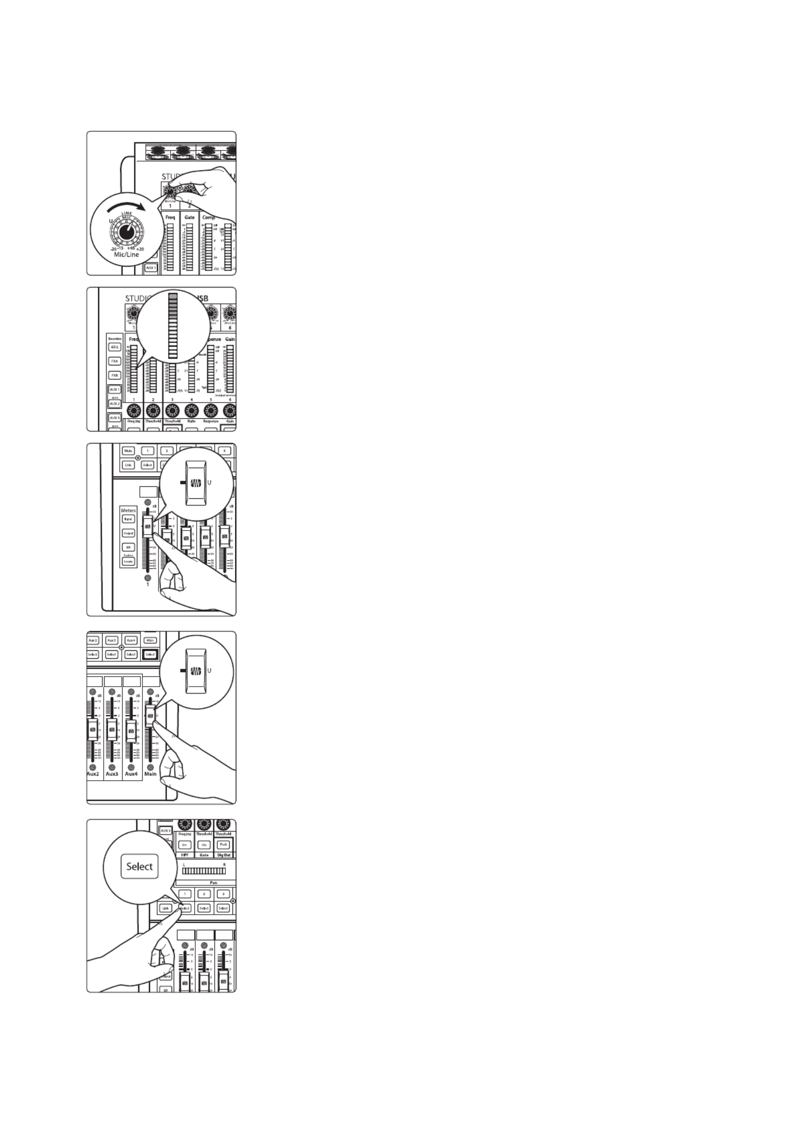
4. Make sure that the Mic/Line knob on Channel 1 is all the way counter-clockwise.
5. Plug your StudioLive into a power outlet and turn it on.
6. If your microphone requires phantom power, engage the 48V button on Channel
1 of your StudioLive, by pressing the Channel 1 Select button, then pressing the
48V button in the Fat Channel.
7. Turn on your amplifier or powered monitors.
8. Press the Input button in the Meter section.
ON
6
2 Getting Started
2.1 Level Setting Procedure
StudioLive™ 16.0.2 USB
Owner’s Manual
9. Speak or sing into your microphone at approximately the
same volume you expect during the performance.
10. Turn the trim knob on Channel 1 clockwise while watching the first meter in the
Fat Channel.
11. Adjust the Channel 1 trim knob until a little more than half of the green LEDs are
lit. The red LED at the top of the meter should never light up.
12. Raise the Channel 1 fader until it reaches “U” (unity gain).
13. Bring up the Main fader until you can comfortably listen to your microphone
through your speakers.
14. Press the Channel 1 Select button.
15. Use the Fat Channel to add dynamics processing and EQ.
7
3 Hookup
3.1 Rear-Panel Connections
StudioLive™ 16.0.2 USB
Owner’s Manual
3 Hookup
3.1 Rear-Panel Connections
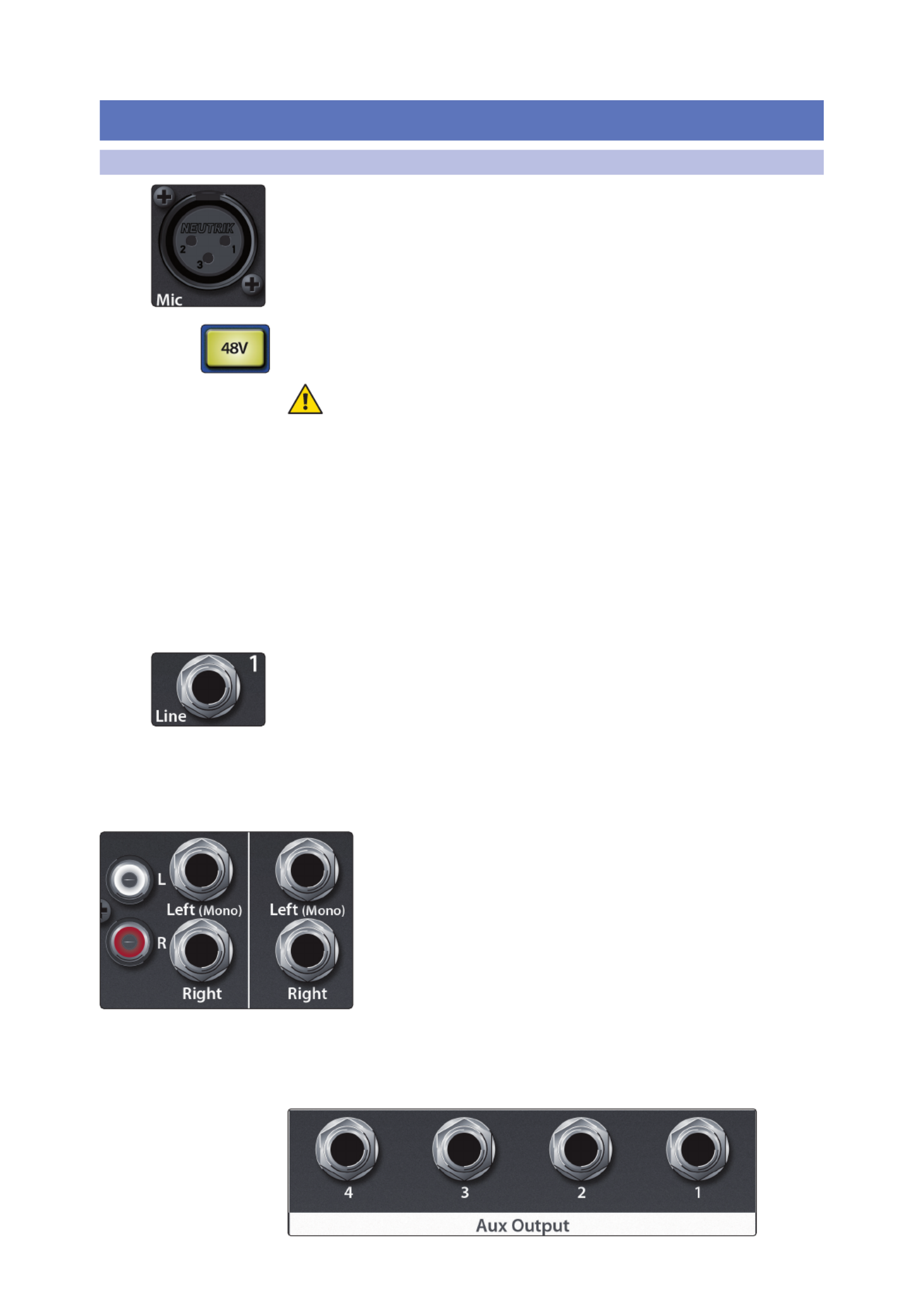
Microphone Inputs. Your StudioLive is equipped with 12 PreSonus XMAX
microphone preamplifiers for use with all types of microphones. The XMAX
preamplifier has a Class A input buffer, followed by a dual-servo gain stage. This
arrangement results in ultra-low noise and wide gain control, allowing you to boost
signals without increasing unwanted background noise.
48-volt Phantom Power. The StudioLive provides 48V phantom power for the
microphone input on each channel. This feature can be individually enabled for each
channel using the 48V button in the Fat Channel. for details.See Section 4.1
WARNING: Phantom power is required for condenser microphones but can
severely damage dynamic mics, especially ribbon mics. Therefore, switch
phantom power off for all channels where it is not required.
Power User Tip: Dynamic microphones and ribbon microphones are generally lower-
output devices and require no external power source. The most important thing to note
about ribbon microphones is that they very rarely require phantom power. In fact, unless
a ribbon microphone calls specifically for phantom power, sending phantom power to it
can cause severe damage – probably beyond repair. Condenser microphones are
generally more sensitive than dynamic and ribbon microphones and typically require
external +48V phantom power. Always review your microphone’s documentation to
ascertain the manufacturer’s recommended operating practices.
XLR connector wiring for phantom power:
Pin 1 Pin 2 Pin 3 = GND = +48V = +48V
Line-level Input. Each channel of the StudioLive has a balanced, ¼-inch TRS
connection for line-level input. When these inputs are engaged, the microphone-
preamp circuit is bypassed. Typical examples of line-level connections are synthesizer
outputs, CD/DVD-player outputs, and (with exceptions) signal-processor outputs.
Note: As with any mixer, plugging in a microphone or a line-level input device, or turning
phantom power on or off, will create a momentary spike in the audio output of your
StudioLive. Because of this, it is highly recommended that you mute or turn down the
channel trim before changing connections or turning phantom power on or off. This
simple step will add years to life of your audio equipment.
Stereo Inputs. Channels 9 through 16 are stereo inputs. Each pair of
channels is controlled by a single fader, Solo, Mute, and Select button.
By default, Channels 9/10 through 15/16 are set to be mono, so that only
the mic and line inputs of the Left (mono) channel will be heard. When
these channels are unlinked, the Right input is not accessible on the
mixer. To insert the Right input into your mix, you must engage Stereo
Link (see Section 4.2 for details).
RCA Inputs. Channels 13/14 and 15/16 have unbalanced RCA
connections, in addition to the balanced TRS connections.
Like the TRS connections, the right RCA input will not be
accessible on the mixer if the channels are not linked.
Aux Outputs. The StudioLive is equipped with four auxiliary
outputs. In , we discuss in detail how to create aux Section 5.2.4
mixes for monitoring. Aux mixes are routed to these outputs.

8
3 Hookup
3.1 Rear-Panel Connections
StudioLive™ 16.0.2 USB
Owner’s Manual
Talkback Mic Input and Trim. The StudioLive does not have an onboard talkback
mic; an external mic must be used. Phantom power is always enabled on this
microphone preamp, so you can use either a dynamic or a condenser microphone.
This is the trim control adjusts the gain of the Talkback input.
WARNING: Phantom power is only required for condenser microphones and can
severely damage dynamic mics, especially ribbon mics. We recommend that you
consult the documentation that came with your microphone to confirm that it is safe to
use with phantom power before connecting a dynamic microphone to the Talkback
input.
Mono Output and Trim. This balanced XLR output carries a mono,
summed version of the stereo signal from the main bus. The knob
controls the maximum level of the Mono Output signal. The signal can
be attenuated to -80 dB and boosted up to +6 dB.
Main Output and Trim. The StudioLive features both
XLR and balanced, ¼-inch TRS main outputs. These
outputs are parallel both to each other and to the mono
output. The knob controls the maximum output level of
the XLR and TRS main outputs. The signal can be
attenuated to -40 dB and boosted up to 0 dB.
Power User Tip: All main outputs (XLR Stereo, TRS Stereo,
and XLR Mono) of the StudioLive are active all the time.
Because of this, you can send your main mix to five speakers
at the same time. This can be especially useful when you
need to send a mix to another room or add another set of
speakers to accommodate a larger venue.
Monitor Output. These are the balanced ¼” TRS control-room outputs.
The level is controlled by the Monitor knob in the Monitor section on the
top panel.
MIDI I/O. MIDI stands for “Musical Instrument Digital Interface.” However,
MIDI has uses well beyond instruments and sequencing. The MIDI inputs
and outputs allow connection to, and communication with, external
MIDI equipment. One function of these ports is to serve as a standard
MIDI interface, useful for sequencing and myriad other applications. The
MIDI input can also be used to connect a MIDI footpedal to control
certain parameters on your StudioLive. More information about MIDI
Control Mode can be found in Section 6.5.
Power User Tip: MIDI data represents performance information and is not
audio; however, it is frequently used to trigger or control an audio source,
such as a plug-in or synthesizer. When using MIDI, please ensure that your
MIDI data is correctly sent and received by the appropriate hardware or
software instruments. You may also need to route those devices’ audio
outputs to StudioLive input channels. Please consult the user’s manual of
your MIDI devices for help with MIDI setup and usage.

9
3 Hookup
3.1 Rear-Panel Connections
StudioLive™ 16.0.2 USB
Owner’s Manual
USB Port. This female USB-B jack provides connection to a computer for audio
interfacing and control.
2 Amp Fuse. This is the StudioLive’s fuse housing. Your StudioLive uses a 5 mm x 20
mm, 250 VAC, fast-acting fuse.
Power-Input. This is where you plug in the provided IEC power cable.
Power Switch. Push the top part of the switch ( | ) to turn on your StudioLive. Push
the bottom part of the switch ( O ) to turn it off.

10
3 Hookup
3.2 Typical Basic Band Hookup Diagram
StudioLive™ 16.0.2 USB
Owner’s Manual
3.2 Typical Basic Band Hookup Diagram
Bass/DIRhythm Guitar and Amp Drum Set
Lead Vocal Mic
Keyboard
Front-of-House SpeakersMonitorsLaptop MIDI Pedal

11
3 Hookup
3.3 Business Conference Hookup Diagram
StudioLive™ 16.0.2 USB
Owner’s Manual
3.3 Business Conference Hookup Diagram
Powered Speakers
Assisted-Listening
Transmitter
Laptop
Microphones Wireless Microphones
and Receivers
DVD player iPod

12
4 The Fat Channel
4.1 The Select Button
StudioLive™ 16.0.2 USB
Owner’s Manual
4 The Fat Channel
The revolutionary Fat Channel is the heart of the StudioLive. The Fat Channel
makes dynamics, routing, and panning for every input and output on the
StudioLive available at the touch of a Select button. The 12 multipurpose
knobs and meters located in the Fat Channel control nearly every adjustment
you will need to make on your StudioLive. From the Fat Channel, you can:
4
Add dynamics processing and EQ to every input and output
4
Create aux and effects mixes for all four analog aux
buses and both internal effects buses
4
Engage phantom power for each mic preamp.
4Meter input level and gain reduction for all 16 channels
4
Meter output level for all four aux buses and the Main output
4
Copy, save, and load Fat Channel and GEQ presets
4
Recall your fader position for stored mixes
4.1 The Select Button
Select Buttons. Above each fader and in both FXA and FXB master sections, you will
find Select buttons. There is a Select button on each of the 12 channels, each of the 4
analog aux buses, both internal effects buses, and the main output bus. Each of
these buttons serves the same purpose: to access the Fat Channel parameters for its
channel or bus.
Selected Channel Display. In the lower right corner of the Fat Channel, you will find
an LED readout. The currently selected channel will always be displayed here as
follows:
4
Numbers 1-8: The corresponding mono channel (1-8) is selected.
4
9, 11, 13, or 15: The corresponding stereo channel (9/10 – 15/16) is selected.
4MA: Main bus is selected.
4
A1-A4: The corresponding Aux bus (1-4) is selected.
4Fa: EFX A is selected.
4Fb: EFX B is selected.

14
4 The Fat Channel
4.3 Dynamics Processing and EQ
StudioLive™ 16.0.2 USB
Owner’s Manual
engaged, Channel 7’s settings will be copied onto Channel 8. Because the settings are
copied nondestructively, it is possible to A/B dynamics settings with the touch of
two buttons.
Whichever channel is selected when the Link button is engaged will be
the Link Master. When either channel in the stereo link is selected, both
channels’ Select buttons will illuminate but the Link Master‘s ID number will
be displayed in the Selected Channel LED read-out in the Fat Channel.
The exception to this is the four stereo channels (Channels 9/10-15/16). For
these channels, the stereo link will enable the right side (channels 10, 12,
14, and 16) to be heard in your mix. Each of these stereo channels’ fader,
Select button, MultiMode button, and Aux send control both channels at
the same time. All Fat Channel settings are applied to both channels.
Power User Tip: It should be noted that while Stereo Link must be enabled in order to
hear the right side of each stereo channel through the StudioLive, the right inputs are still
sent to the USB bus and can be recorded by your DAW with or without Stereo Link
engaged. For more information on using your StudioLive as an audio interface, please
consult the StudioLive 16.0.2 USB Software Library Reference Manual.
4.3 Dynamics Processing and EQ
The main function of the Fat Channel is to provide dynamics processing and
filtering for every input and output on the StudioLive. The rotary encoders
work in conjunction with the meters directly above them to adjust the
dynamics processing and EQ. The Fat Channel’s processing section consists
of five parts: High-Pass filter, Noise Gate, Compressor, Limiter, and Semi-
Parametric EQ. Each can be turned on or off and controlled separately.
The signal flows as follows:
4.3.1 Fat Channel Processing Guide
The following table provides a quick guide to the processing that is
available for each bus in the StudioLive, as well as which inputs and buses
are available for recording. For more information on USB sends, please
see the StudioLive 16.0.2 USB Software Library Reference Manual.
Bus Polarity Invert High-Pass Filter Noise Gate USB SendCompressor EQ Limiter
Input Channels X X X X X X X
Main Out L/R X X X X
Aux Buses X X X X X X
EFX A and EFX B X X X X X X
Hi-Pass LimiterEQØ Noise Gate Compressor

16
4 The Fat Channel
4.3 Dynamics Processing and EQ
StudioLive™ 16.0.2 USB
Owner’s Manual
Gate Threshold. Sets and Displays the Threshold of the Gate for the Selected
Channel.
This encoder sets, and the meter displays, the gate threshold for the
selected channel. The threshold determines the level at which the gate
will open. Essentially, all signals above the threshold setting are passed
through unaffected. You can set the threshold from 0 to -56 dB.
Power User Tip: If the threshold is set fully counterclockwise, the gate is turned off (always
open), allowing all signals to pass through unaffected.
4.3.4 Compressor and Limiter
Available for all input and output buses, the Fat Channel
provides both a Compressor and a Limiter.
A compressor is a type of amplifier in which gain is dependent on
the signal level passing through it. You can set the maximum level a
compressor allows to pass through, thereby causing automatic gain
reduction above that predetermined signal level, or threshold.
Compression refers, basically, to the ability to reduce, by a fixed ratio, the amount
by which a signal’s output level can increase relative to the input level. It is useful
for lowering the dynamic range of an instrument or vocal, making it easier to
mix audio without distorting the outputs. It also assists in the mixing process
by reducing the amount of level changes needed for a particular instrument.
Compressor On/Off. Turns the Compressor On/
Off for the Selected Channel or Output Bus.
This button engages or disengages the compressor for the selected channel or
output bus. It will illuminate to indicate that the compressor has been enabled.

17
4 The Fat Channel
4.3 Dynamics Processing and EQ
StudioLive™ 16.0.2 USB
Owner’s Manual
Compressor Threshold. Sets and Displays the Threshold of the
Compressor for the Selected Channel or Output Bus.
This encoder sets, and the meter displays, the compressor threshold for
the selected channel or output bus. When the signal’s amplitude (level)
exceeds the threshold setting, the compressor engages. Turning the
knob counterclockwise lowers the threshold so that compression begins
at a lower amplitude. The threshold can be set from -56 to 0 dB.
Compression Ratio. Sets and Displays the Compression
Ratio for the Selected Input Channel or Output Bus.
This encoder sets, and the meter displays, the compression ratio (or slope) for the
selected channel or output bus. The ratio sets the compression slope, which is a
function of the output level versus the input level. For example, if you have the
ratio set to 2:1, any signal levels above the threshold setting will be compressed at a
ratio of 2:1. This means that for every 2 dB of level increase above the threshold, the
compressor’s output will only increase 1 dB. The ratio can be set from 1:1 to 14:1.
Compressor Auto Mode Button. Enables Automatic Response Mode.
When Auto mode is active, the Response control becomes inoperative,
and a preprogrammed attack and release curve is used. In this
mode, the attack is set to 10 ms, and the release is set to 150 ms. All
other compressor parameters can still be adjusted manually.
Compressor Response. Sets and Displays the Compressor Response
Setting for the Selected Input Channel or Output Bus.
This encoder sets, and the meter displays, the compressor’s response
setting for the selected channel or output bus. The Response control sets
the attack and release tapers for the Compressor simultaneously. A tight
response time triggers the compressor immediately and returns the gain
reduction back to zero quickly when the signal drops below the compressor
threshold. A smooth response time allows the beginning component of
the signal or “initial transient” to pass through, uncompressed, and extends
the time of length of time before the gain reduction returns to zero.
Power User Tip: In general, a tighter response time should be used for instruments with
relatively few transients, like drums and percussion, while a smooth setting should be
using for instrument with a lot of transients, like vocals and stringed instruments.
Compressor Makeup Gain. Sets and Displays the Amount of Makeup Gain
for the Compressor on the Selected Input Channel or Output Bus.
This encoder sets, and the meter displays, the makeup-gain setting of the
compressor for the selected channel or output bus. When compressing a signal, gain
reduction usually results in an overall attenuation of level. The gain control allows
you to restore this loss in level and readjust the volume to the precompression level
(if desired). You can adjust Makeup Gain from 0 dB (no gain adjustment) to +28 dB.
Limiter On/Off. Turns on the Limiter for the Selected Input Channel or Output Bus.
When the limiter is engaged the button will illuminate. The
threshold for the limiter is set to 0 dBFS. The Ratio is ∞:1.
The limiter is also available for all input and output buses.
Power User Tip: At the simplest level, a limiter is a compressor that is set to prevent any
increase in the level of a signal above the threshold. For example, if you have the
threshold knob set at 0 dB, and the ratio turned fully clockwise, the compressor becomes
a limiter at 0 dB, so that the output signal cannot exceed 0 dB regardless of the level of the
input signal. Typically, compression ratios of 10:1 and above are considered to be limiting.

18
4 The Fat Channel
4.3 Dynamics Processing and EQ
StudioLive™ 16.0.2 USB
Owner’s Manual
4.3.5 Equalizer
The Fat Channel EQ is available for every input and output bus. This 3-band
semi-parametric EQ provides selectable per-band controls, making it extremely
easy to sculpt the sound of your instruments as well as your overall mix.
Low EQ On/Off Button. Activates Control for the Low
Band EQ for the Selected Input or Output Bus.
This button actives control of the equalizer’s Low band for the selected
channel or bus. The button will illuminate to indicate the band is active.
Low EQ Frequency Control. Sets and Displays the
Center Frequency of the Low EQ Band.
This encoder sets, and the meter displays, the center frequency of the equalizer’s
Low band. The center frequency is the middle of the passband (the mean) between
the lower and upper cutoff frequencies that dene the limits of the band.
You can adjust the center frequency from 36 to 465 Hz.
Low EQ Gain Control. Sets and Displays the Gain
Attenuation or Boost of the Center Frequency.
19
4 The Fat Channel
4.3 Dynamics Processing and EQ
StudioLive™ 16.0.2 USB
Owner’s Manual
This encoder sets, and the meter displays, the gain cut or boost
at the center frequency for the Low band. The level of the
center frequency can be set between -15 and +15 dB.
Low Shelf EQ Button. Turns on the Low Shelving EQ
for the Selected Input or Output Bus.
When the Shelf button is not engaged, the Low band is semi-parametric. Enabling
the Shelf button turns the Low band into a low-shelving EQ that alters, by a xed
amount, a band of low frequencies at and below a user-selected shelving frequency.
Power User Tip: A low shelving EQ is like a bass-control knob on a stereo. In this mode,
the Center Frequency control selects the shelving frequency.
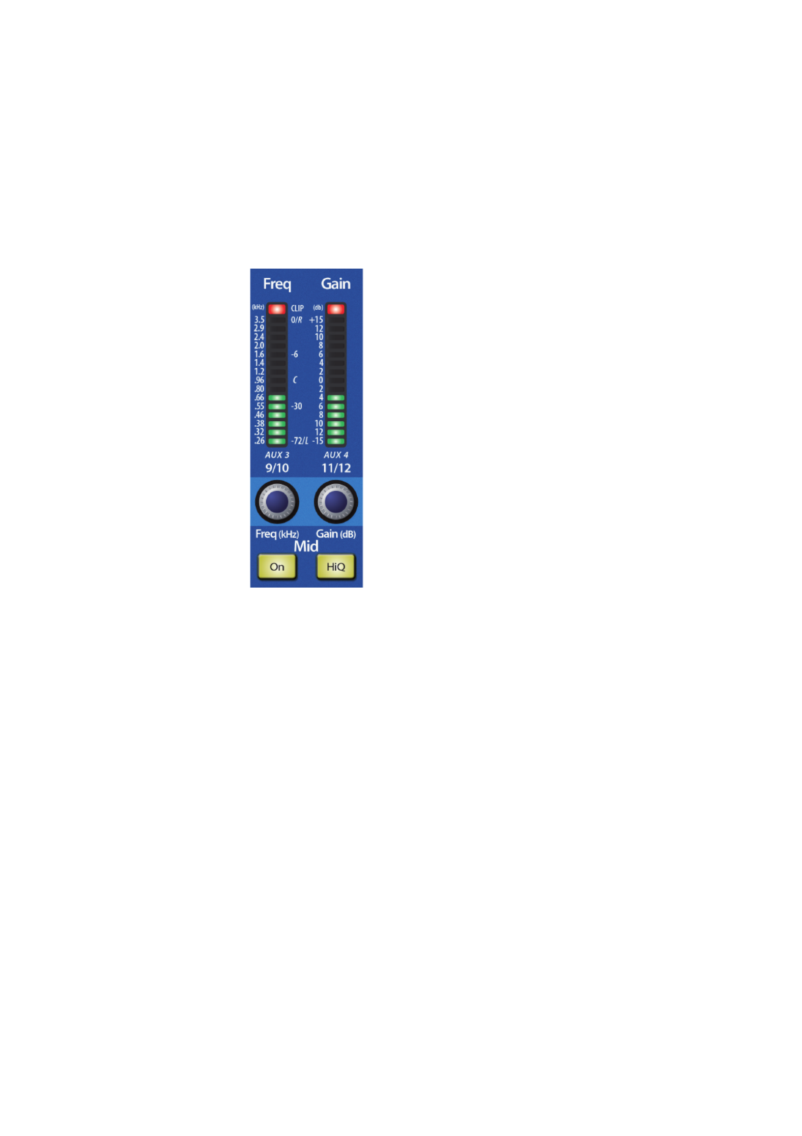
Mid EQ On/Off Button. Activates Controls for the Mid
EQ for the Selected Input or Output Bus.
This button actives the controls for the equalizer’s Mid band for the selected
input or output. The button will illuminate to indicate the band is active.
Mid EQ Frequency Control. Sets and Displays the Center Frequency of the Mid EQ.
This encoder sets, and the meter displays, the center frequency for the Mid
band. You can adjust the center frequency from 260 Hz to 3.5 kHz.
Mid EQ Gain Control. Sets and Displays the Gain Attenuation
or Boost of the Center Frequency for the Mid Band.
This encoder sets, and the meter displays, the gain cut or
boost at the center frequency of the Mid band. The level of the
center frequency can be set between -15 and +15 dB.
Mid Hi Q Button. Enables a Narrow Bandwidth for the Mid
Band EQ on the Selected Input or Output bus.
Q is the ratio of the EQ band’s center frequency to its bandwidth. With a
constant center frequency, higher Q values indicate a narrower bandwidth,
so Q is often equated with bandwidth. By default, the Q is set to a value of
0.55. When the Hi Q button is engaged, the Q setting will be increased to
2.0, thus narrowing the bandwidth to provide more precise control.
20
4 The Fat Channel
4.3 Dynamics Processing and EQ
StudioLive™ 16.0.2 USB
Owner’s Manual
High EQ On/Off Button. Activates Control for the High
EQ for the Selected Input or Output Bus.
This button actives control of the High band for the selected channel
or bus. The button will illuminate to indicate the band is active.
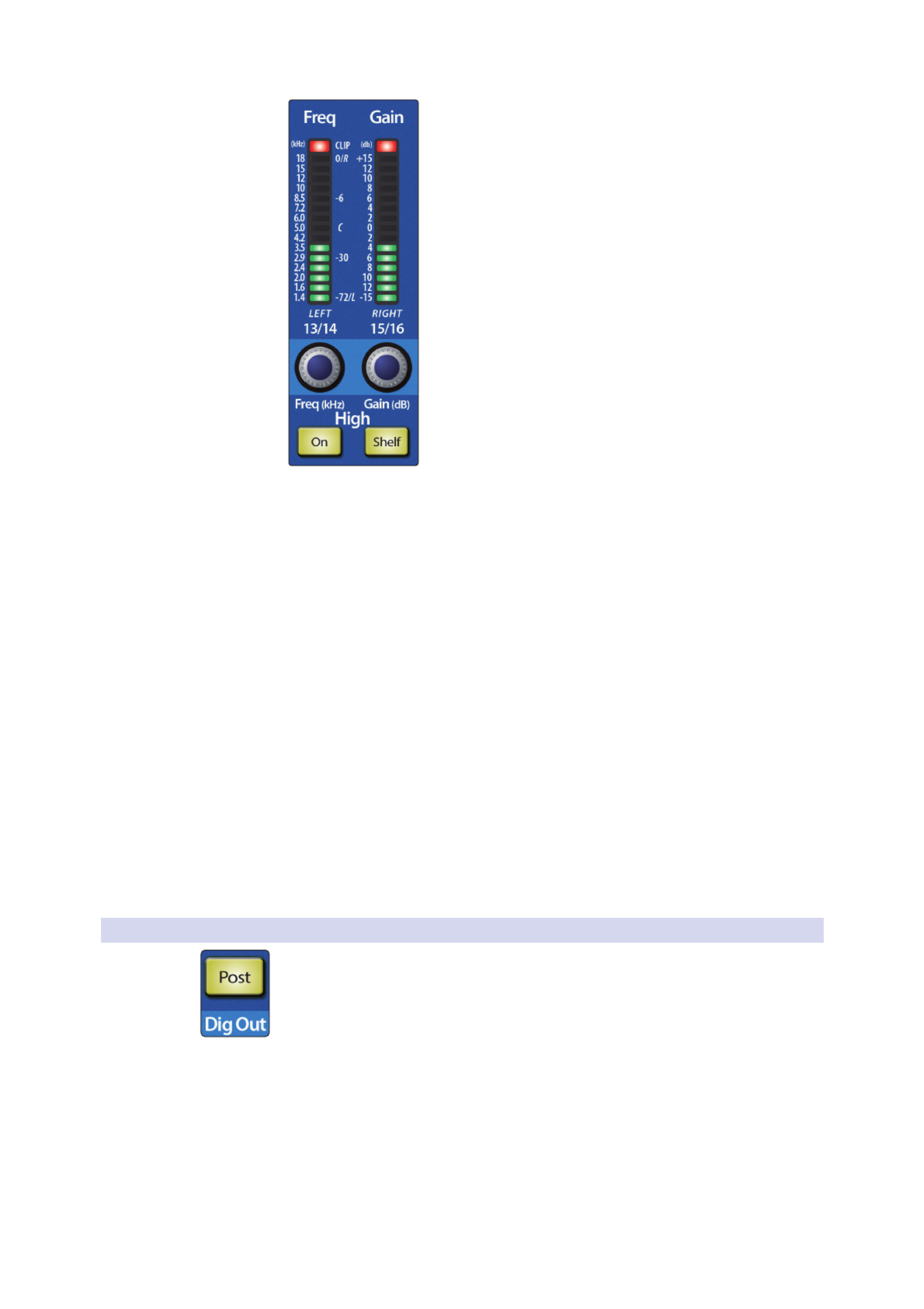
High EQ Frequency Control. Sets and Displays the Center Frequency of the High EQ.
This encoder sets, and the meter displays, the center frequency of the
High band. You can adjust the center frequency from 1.4 to 18 kHz.
High EQ Gain Control. Sets and Displays the Gain Attenuation
or Boost at the Center Frequency of the High EQ Band.
This encoder sets, and the meter displays, the gain cut or boost
at the center frequency of the High EQ band. The level of the
center frequency can be set between -15 and +15 dB.
High Shelf EQ Button. Turns on the High Shelving
EQ for the Selected Input or Output Bus.
When the Shelf button is not engaged, the High band is a semi-
parametric EQ. Enabling the Shelf button turns the High band into
a high shelving EQ that alters, by a fixed amount, a band of high
frequencies at and above a user-selected shelving frequency.
Power User Tip: A high shelving EQ is like a treble-control knob on a stereo. In this mode,
the Center Frequency control selects the shelving frequency.
4.3.6 Dig Out: Recording EQ and Dynamics
The Fat Channel gives you the option of sending just the unprocessed audio to your
computer or including the Fat Channel settings in the recorded signal. When the Dig
Out button is enabled, it will illuminate, indicating that the signal being sent to the
USB bus is post-EQ and post-dynamics processing. When the button is disabled, the
signal being sent to the USB bus is pre-Fat Channel.
The Dig Out button is only available when one of the channel inputs is selected.
The Main bus automatically sends its signal post-Fat Channel dynamics and EQ.
Note: All USB sends are pre-fader except for the Main outputs. For more information on
using your StudioLive as an audio interface, please consult the StudioLive 16.0.2 USB
Software Library Reference Manual.

21
4 The Fat Channel
4.4 Fat Channel Presets: Copy, Paste, Load
StudioLive™ 16.0.2 USB
Owner’s Manual
4.4 Fat Channel Presets: Copy, Paste, Load
In addition to being able to create and save custom Fat Channel
presets, every setting in the Fat Channel can be copied from
one channel or bus to any other channel or bus.
4.4.1 Copying and Pasting
To copy a Fat Channel setting from one channel or bus to any other channel or bus:
1. Press the Copy button. Every Select button on the StudioLive except the button
for the currently selected channel will begin to flash. The Select button for the
selected channel will not illuminate.
2. To paste the current channel’s Fat Channel setting to another channel or bus,
simply press that channel’s Select button. It will stop flashing and will illuminate.
3. After you have selected every channel to which you want the settings pasted,
press the Load button. The StudioLive will return to its normal state, indicating
that the Fat Channel settings have been successfully pasted.
23
4 The Fat Channel
4.4 Fat Channel Presets: Copy, Paste, Load
StudioLive™ 16.0.2 USB
Owner’s Manual
4.4.3 Saving Fat Channel Presets
Fat Channel presets can be saved and customized as you find new and useful
Fat Channel settings you would like to store and use in future mixes.
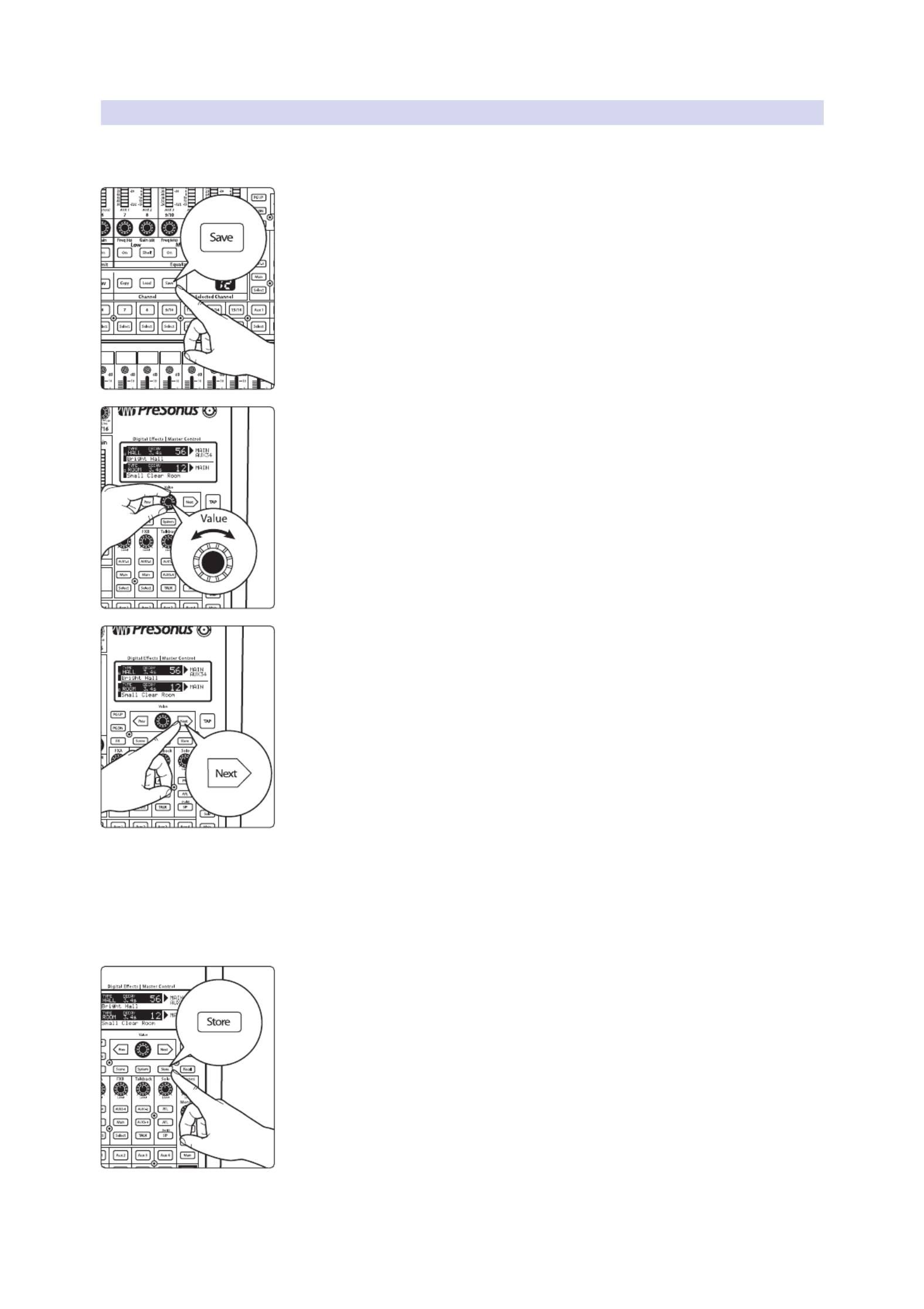
1. If you have created a channel-strip setting in the Fat Channel that you would like
to save to the Channel Preset library, press the Fat Channel’s Save button. You will
notice that the LCD will display the Channel Preset Save menu.
2. To begin, use the Value encoder to scroll to an empty position in the Channel
Preset library.
3. Press the Next button to navigate to the category location. Create the category
in which your preset would fit (DRM, VOX, GTR, etc.).
4. Press the Next button again to navigate to the first letter of the preset name.
5. Turn the Value encoder clockwise or counter-clockwise to change the
letter. The StudioLive allows you to customize the name with uppercase
and lowercase letters, as well as a selection of numerals and punctuation
marks. You can insert a space by simply pressing the Tap button.
6. Once you are satisfied with your changes, press the Store button. It will
illuminate while the Channel preset is being written to the StudioLive’s internal
memory. Once the Channel preset is saved, the Store button will return to its
unlit state.

24
4 The Fat Channel
4.4 Fat Channel Presets: Copy, Paste, Load
StudioLive™ 16.0.2 USB
Owner’s Manual
4.4.4 Channel Presets Library
Your StudioLive comes with 50 Fat Channel presets custom designed by
professional PreSonus users. These presets can be altered, renamed, and
overwritten; however, there are 49 additional empty storage locations
for you to build your own custom library of channel-strip settings.
01 27DRM: Kick 1 GTR: Acoustic Strumming
02 28DRM: Kick 2 GTR: Acoustic Fingerstyle
03 29DRM: Kick Funk 1 KEY: Piano Bright
04 30DRM: Kick Funk 2 KEY: Piano Warm
05 31DRM: Kick Hip-Hop KEY: Piano Jazz
06 32DRM: Kick Jazz KEY: Piano Electric
07 33DRM: Snare 1 KEY: Piano Electric 2
08 DRM: Fat Snare 34 KEY: Vibes
09 35DRM: Snare Crackalak HRN: Trumpet
10 36DRM: Snare Snappy HRN: Trombone
11 DRM: Toms Mid 37 HRN: Sax
12 DRM: Toms Low 38 HRN: Sax Solo
13 DRM: Toms High 39 PRC: Congas
14 40DRM: Overhead Rock PRC: Bongos
15 41DRM: Overhead Jazz PRC: Cowbell
16 DRM: High Hat 42 PRC: Tambourine
17 43BAS: Electric 1 VOX: Male 1
18 44BAS: Electric 2 VOX: Male 2
19 45BAS: Slap VOX: Male 3
20 46BAS: Upright VOX: Female 1
21 47GTR: Rock 1 VOX: Female 2
22 48GTR: Rock 2 VOX: Female 3
23 49GTR: Funk VOX: Speech 1
24 50GTR: Metal VOX: Speech 2
25 GTR: Jazz 51 -
99 EMPTY LOCATION
26 GTR: Acoustic

25
4 The Fat Channel
4.5 Metering
StudioLive™ 16.0.2 USB
Owner’s Manual
4.5 Metering
The StudioLive offers flexible metering at the touch of a button.
The 12 meters in the Fat Channel section can monitor:
4
The input signal for each channel, post-gain and
pre-dynamics, pre-EQ, and pre-fader
4The gain reduction for each input channel
4
The output level for each of the four Aux buses
4The output level of Main bus
Finally, the meters can be used to recall the fader settings for a saved Scene.
4.5.1 StudioLive Metering Controls
The Meters section of the StudioLive is located to the left of the fader bank.
Each of these buttons are toggle switches; you turn them on and off by pressing
them. The meter state can also be changed by pressing another button in the
Meter section, or any Select button on the StudioLive, or one of the Aux Encoder
Mode buttons. for more information on Aux Encoder Modes.See Section 5.2
Power User Tip: It is important to mention that the meters simply overlay the selected Fat
Channel state. For instance, if you have Channel 1 selected and then press the Output
button in the Meter section, the knobs and buttons in the Fat Channel section will still be
active. The advantage of this is that you can make adjustments in the Fat Channel while
monitoring your entire mix.
Input Metering Button. Turns PFL Input Metering On and Off.
Switches the meters to display the pre-dynamics, pre-fader level of the input bus.
Meters are one to one (Meter 1 shows the level of Channel 1, etc.). The input signal
for stereo channels that are stereo linked is a sum of the left and right inputs.
Output Metering Button. Turns AFL Output Metering On and Off.
Switches the meters to display the post-dynamics, post-fader level of the
Aux and Main buses. Only the last six meters are used. Meter 7 displays
Aux 1 output, Meter 8 displays Aux 2 output, Meter 9/10 displays Aux
3 output, Meter 11/12 displays Aux 4 output, and Meters 13/14 and
15/16 display the left and right side, respectively, of the Main bus.
Gain Reduction Metering Button. Turns Gain Reduction Metering On and Off.
Displays the amount of gain reduction being applied to each input
channel. Meters have a one-to-one relationship with channels (that
is, Meter 1 shows the gain reduction of Channel 1 and so on).
Fader Locate Button. Turns Fader-Recall Metering On and Off.
Displays the fader position of the stored Scene. When recalling a fader position,
adjust the fader until only the center LED is visible in its meter. To recall the stored
position of an Aux or Main fader, simply move the fader. The meters will instantly
flip to display the stored position of each of the output faders. The same meters
that display the outputs are used for locate. for details.See Section 6.2.4

26
5 Basic Controls
5.1 Input Channel Controls
StudioLive™ 16.0.2 USB
Owner’s Manual
5 Basic Controls
The StudioLive is equipped with all of the standard input controls of an analog
mixer. In addition, the StudioLive provides the added flexibility of routing a playback
stream from your audio-recording software to the mixer via the USB bus, just as if
it were an analog input. This lets you incorporate digital audio tracks into the main
mix and insert plug-in effects and software instruments from your audio program.
See the StudioLive 16.0.2 USB Software Library Manual for more information.
5.1 Input Channel Controls
Input Channel Select Button. Enables Fat Channel Processing and Routing.
Pressing the Select button brings the Fat Channel for its channel into focus,
allowing you to add dynamics processing, EQ, panning, and more.
Input Channel MultiMode Button. Engages USB Return, Solo, and Mute.
This button’s function is determined by the MultiMode control switches. Depending
on which mode is engaged, this button will function as the USB Return, Solo, or Mute
button for its input channel. For more information on the MultiMode buttons and
their functions, please refer to Section 5.3.
Channel Fader. Controls the Overall Level of the Channel.
Each input channel features a 60 mm fader for level
adjustment. Unity gain (0 dB) is denoted by a “U.”
The white area above the fader can be used as a scribble strip. Use only
oil pencils; other types of pens or pencils cannot be wiped off.
To clean the scribble strip, use a lightly damp cloth to remove the writing.

28
5 Basic Controls
5.2 Aux and FX Buses
StudioLive™ 16.0.2 USB
Owner’s Manual
5.2.2 Internal FX Bus Controls
Just to the right of the Fat Channel, you will find the master bus controls for the two
internal effects buses, EFX A and EFX B:
Internal Effects Bus Select Button. Enables Fat Channel Viewing.
The Select button brings the Fat channel for its Effects Bus into
focus, allowing you to add dynamics processing and EQ.
Main Assign Button. Assigns/Unassigns FX bus to Main Output.
This button will route its internal effects (EFX) bus to the Main output.
It will illuminate yellow when the bus is patched to the Mains. To
mute the effect bus in the Main output, simply unassign it.
Aux Assign Button. Assigns/Unassigns FX bus to Aux 1-4.
This button will route its internal effects (EFX) bus to all four Aux
outputs. It will illuminate yellow when the bus is patched to the aux
buses. To mute the effect bus in the auxes, simply unassign it.
FX Level Control. Adjusts the Master Level of the Effects Send Mix.
This knob controls the overall output level of the internal effects mix.
5.2.3 Aux and FX Bus Channel Sends
In addition to setting the dynamics for each channel and bus, and metering each
channel and output, the Fat Channel allows you to create aux mixes and quickly view
the send level for each channel.
The Encoder Mode buttons to the left of the Fat Channel are used
for this purpose. Each of these buttons allows you to view and
set the send level for each channel to that aux or FX mix.
FXA and FXB Encoder Mode Buttons. Enables FXA
or FXB Bus Mixing in the Fat Channel.
When one of these buttons is enabled, the 12 encoders in the Fat Channel become
the FX-send level controls for each of their respective input channels to the enabled
bus (FXA or FXB). The meters will display the send amount of each of the input
channels. The encoders for the stereo channels set the send level for both the Left
and the Right input, provided that stereo linking is enabled. See Section5.1 for details.
Aux 1-4 Encoder Mode Buttons. Enables Aux Mixing in the Fat Channel.
When any of these button is enabled, the 12 encoders in the Fat Channel become the
aux-send level controls for each of their respective input channels to enabled Aux
bus (Aux 1-4). The meters will display the send amount of each of the input channels.
The encoders for the stereo channels set the send level for both the Left and the
Right input, provided that stereo linking is enabled. See Section 5.1 for details.
When an Aux pair is Stereo linked, the Aux 2 and Aux 4 buttons enable pan
control for each channel in the Aux pair, and the 12 encoders in the Fat Channel
become the pan controls for each of their respective input channels. The meters
will display the pan setting of each of the input channels. Use Aux 1 and Aux 3
Encoder mode buttons to set the send level of each channel to the aux pair.

29
5 Basic Controls
5.2 Aux and FX Buses
StudioLive™ 16.0.2 USB
Owner’s Manual
5.2.4 Creating Monitor Mixes
Creating custom monitor mixes is critical. If musicians can’t hear themselves or their
bandmates, their performance will suffer. A monitor mix can be mono or stereo.
Most often, an individual live monitor mix is mono and is sent to a floor-wedge or
sidefill monitor. (The obvious exception is in-ear monitor systems.) A studio monitor
mix is usually stereo and is sent to a headphone amplifier, so it requires both a left-
and a right-channel input. In both cases, the function of the aux bus is the same.
As an example, let’s create a mono monitor mix on Aux 1.
1. To begin, press the Aux 1 Encoder Mode button. The Fat Channel meters will
display the send level of each of the input channels to Aux 1. The encoders
below each meter control the channel’s level in Aux 1’s mix.
2. Use the encoders the same way that you use the faders to set the output level to
your main mix. Ask your musicians what they would like in their monitor mix and
use their requests as a starting point.
3. By pressing the Select button for Aux 1, you can add dynamics processing and
EQ to the overall monitor mix. These are especially useful for eliminating
feedback in a monitor. Keep in mind that an equalizer can also be used to
increase the presence of an instrument by boosting that particular frequency
range without necessarily boosting the volume in the mix. This is great for
getting the lead guitar to cut through in the guitarist’s monitor mix and to
provide that extra rumble in the bassist’s mix.
4. Use the Aux 1 fader to control the level of the entire aux mix.
You can listen to the aux mixes you are creating, using your
headphones or your control-room monitor, by simply soloing the
aux and selecting Solo as the source in the Monitor section.
To solo Aux 1, press the Solo MultiMode switch and then press the Aux 1 MultiMode
button.

30
5 Basic Controls
5.2 Aux and FX Buses
StudioLive™ 16.0.2 USB
Owner’s Manual
5.2.5 Creating Internal FX Mixes
There are at least two main advantages to creating an FX mix, rather than
inserting an effect in a channel. First, several channels can be sent to a single
processor. In addition to greatly simplifying the number of parameters you
have to control, this can create a cohesive sound in your mix. The second
advantage of creating an FX mix is that you can vary the level sent from each
channel to the processor, rather than patching the output directly into the
effect. This allows you to add a lot or a little of an effect to any given channel.
The StudioLive features two internal effects buses. These are used much
in the same way the aux buses are used to create monitor mixes.
1. To begin, decide to which outputs you’d like to route your FX mix and then press
the appropriate assign button in the FXA bus. For example, if you would like hear
the effects in your Main mix, press the Main assign button.
2. Next, press the FXA Encoder Mode button. The Fat Channel meters will display
the send level of each of the input channels to FXA. The encoders below each
meter control the channel’s level in FXA’s mix. Use these encoders the same way
that you use the faders to set the output level to your main mix. The higher a
channel’s level is in the FX mix, the more processed (“wetter”) it will sound.
Let’s say that you are using reverb to liven up a relatively dead room. You
might send a little bit of each input to the reverb, but you probably will not
want much of the drums and bass to be processed, as too much reverb could
reduce their impact and leave your mix without a sturdy foundation. So rather
than turning the aux-send level for the kick drum channel all the way up,
turn it so that the meter reads between 20% and 30% saturation. This way,
only a small portion of the kick drum input will be affected by the reverb.
By pressing the FXA Select button, you can add dynamics processing and EQ to the
overall FXA mix. These are great for adding sustain, removing too much ring, etc.
Use the FXA Level knob to increase or decrease the overall FX Mix Send Level.

32
5 Basic Controls
5.4 Main Output Bus
StudioLive™ 16.0.2 USB
Owner’s Manual
When a channel or bus is soloed, it will automatically be
selected, and its Select button will illuminate.
Power User Tip: When Solo In Place is engaged, Solo mode will display both the solos
and subsequent mutes across the MultiMode buttons; that is, if you solo Channel 1 while
in Solo In Place, Channel 1’s MultiMode button will illuminate yellow; all other MultiMode
buttons will illuminate red. However, any MultiMode button you engage will solo that
channel.
5.3.3 Mute Button
When Mute mode is engaged, the MultiMode buttons on each channel function as
the Mute buttons for each channel and aux. When a MultiMode button is engaged
while in this mode, it will mute its channel to the Main and Aux outputs.
While in Mute mode, each MultiMode button that is enabled will
illuminate red to alert you that the channel is muted.
5.4 Main Output Bus
Main Select Button. Enables Fat Channel Viewing.
The Select button brings the Fat Channel for the Main bus into
focus, enabling you to add dynamics processing and EQ.
Main Fader. Controls the Level of the Main Output.
The fader controls the overall level of the main stereo output.
The white area above the fader can be used as a scribble strip. Use only
oil pencils. Other types of pens or pencils cannot be wiped off.
To clean the scribble strip, use a lightly damp cloth to remove the writing. Spit works
pretty well, too.
5.5 Talkback System
The StudioLive features a Talkback microphone input on the back panel. This can be
routed to the aux outputs. It is important to note that the aux outputs are grouped in
this section. For example, if you are using Aux 3 as the monitor mix to the bass
player’s floor wedge and Aux 4 as the mix to the keyboard player’s in-ear monitors,
the talkback signal will be sent to both monitors—so don’t say anything you
wouldn’t want both to hear!
Power User Tip: If your musicians are using in-ear monitoring on stage, they can feel
isolated from the audience and require an ambience microphone. You can use the
Talkback input for this purpose instead of using a channel.
Talkback Mic Level. Controls the Overall Level of the Talkback Mic.
This knob controls the overall volume of the Talkback mic
input. The trim for the Talkback mic is located on the back
panel next to the input. See Section 3.1 for details.
Output Select Buttons. Assigns the Talkback Mic to the Aux 1-2 or Aux 3-4.
These buttons assign the talkback mic to the specified outputs. These buttons
are toggled on/off and will illuminate to indicate that the Talkback output is
active. The talkback mic can be assigned to every aux output at the same time.
Talk Button. Turns the Talkback Mic On/Off.
This latching button turns the talkback mic on and off. It will
illuminate to indicate that the talkback mic is active.

33
5 Basic Controls
5.6 Solo Bus
StudioLive™ 16.0.2 USB
Owner’s Manual
5.6 Solo Bus
The StudioLive features an independent Solo bus. This feature is extremely
useful in setting levels for monitor mixes, dialing in dynamics processing on each
channel, and fixing issues during a live show without interrupting the main mix.
Solo Bus Level Control. Adjusts the Overall Volume of the Solo Bus.
This knob adjusts the overall level for the Solo bus.
PFL Toggle Button. Enables PFL Solo Mode.
The PFL button engages Pre-Fader Listening in the Solo bus. Soloing on any channel
or aux bus routes it to the Solo bus and has no effect on the main or aux mixes.
Aux bus soloing is always PFL, regardless of whether this mode is engaged.
Power User Tip: PFL sends the input channel’s signal to the Solo bus before it reaches the
fader, so the fader does not affect the soloed signal.
AFL Toggle Button. Enables AFL Solo Mode.
The AFL button engages After-Fader Listening in the Solo bus. Soloing
on any channel or aux bus routes it to the Solo bus and has no effect on
the main or aux mixes. The AFL is not available on the aux buses.
Power User Tip: AFL sends the input channel’s signal to the Solo bus post-fader so that
you can control the level of the soloed signal with the fader. This is the StudioLive’s default
setting.
SIP (Solo In Place) On/Off Button. Enables Solo In Place Mode.
SIP (Solo In Place), or “destructive soloing,” mutes every unsoloed channel on
the StudioLive. The muted channels will be muted in the Main outputs. Note
that while you can manually unmute a channel, this mode should be used with
extreme caution during a live performance. Only the input channels can be
placed into destructive soloing. The Aux buses are omitted from SIP mode.
To enable SIP, press and hold the button until it illuminates red. This ensures
that you cannot enter into destructive Solo mode by accident.
Power User Tip: SIP (Solo In Place) is also known as “destructive solo.” When channels are
soloed in this mode, every channel that isn’t soloed will be muted, and only the soloed
channels will be sent to their assigned outputs. While useful in dialing in dynamics during
soundcheck, this mode is dangerous during a live show. We recommend that this mode
be turned off when mixing live events.
Destructive soloing is also a great way to tune each channel’s dynamics individually in
live-mixing situations or do surgical editing in the studio. SIP mode mutes every channel
and bus that is not soloed in the Main bus (that is, if Channel 3 is soloed, you will only
hear Channel 3 in your mains). This makes a great fine-tuning tool but it can quickly
destroy a live mix. Again, we highly recommend that you drop out of this mode once the
show has started.

36
5 Basic Controls
5.7 Monitor Bus
StudioLive™ 16.0.2 USB
Owner’s Manual
5. The Fat Channel will display the dynamics processing, EQ, output routing, and
pan settings for the kick drum. Using the encoders and meters in the Fat
Channel, set up the compressor and EQ for this channel.
6. Once you are satisfied, bring the channel fader back down.
7. Next, press the MultiMode button on the snare-mic channel and repeat steps
4-6. In this way continue with each drum mic, then move on to the other
instruments that are connected to your StudioLive. When you have finished with
all the instruments, press the SIP button again and slowly bring up your faders to
set up your mix.
5.7 Monitor Bus
The StudioLive features a headphone output and control-room outputs, giving you
the ability to monitor multiple sources on the StudioLive. The Monitor bus on the
StudioLive allows you to monitor the main outputs, Solo bus, and the main USB
return from your computer. Because the Monitor bus is a summing amp, you can
even monitor the World Series on your headphones while running sound at a show.
Phones Level. Adjusts the Overall Level of the Headphone Output.
This knob adjusts the overall level for the headphone output.
The Headphone output is located on the front of the mixer, below the main fader.
Monitor Level. Adjusts the Overall Level of the Monitor Output.
This knob adjusts the overall level of the control-room monitor outputs.
USB Button. Assigns USB Returns 1 and 2 to the Monitor Bus.
The USB Monitor button patches USB returns 1 and 2 to the monitor bus. The level
for this input is controlled by the level set in the computer application (such as Studio
One Artist) that is playing the audio. For more information about the main USB
returns, please review the StudioLive 16.0.2 USB Software Library Reference Manual.
Solo Button. Assigns the Solo Bus to the Monitor Outputs.
The Solo Bus Monitor button patches any soloed channel or aux bus to
the monitor bus. This can be useful in a number of ways. For example:
4Auditioning an aux-send monitor mix
4Dialing in the dynamics processing and EQ on a channel or aux mix
4
Creating a better blend for instrumental sections (horns, strings, etc.)

37
5 Basic Controls
5.7 Monitor Bus
StudioLive™ 16.0.2 USB
Owner’s Manual
Main Button. Assigns the Main Mix to the Monitor Bus.
The Main Mix Monitor button routes the same signal that is being sent from
the main outputs to the monitor bus. This signal is always pre-fader.
Power User Tip: Because the monitor bus is a summing amp, you can listen to the solo
and main buses at the same time. By summing the main mix and the solo bus, you can
raise the volume of the channel you’re tweaking without affecting the mix the audience
hears. To do this, enable both the main mix and the solo bus in your monitors. Solo the
channels you need to work on and raise the Solo Output level so that the channels are
louder than the main mix. This is especially useful when trying to determine the source of
an odd frequency or tone in mid show.

38
6 Digital Effects | Master Control
6.1 The Digital FX (Effects) Menu
StudioLive™ 16.0.2 USB
Owner’s Manual
6 Digital Effects | Master Control
From the Digital Effects | Master Control section, you can select and
change the parameters of the two internal effects processors, and you
can store and recall every setting on the StudioLive. Because almost all
StudioLive features are controlled from the mixing surface (rather than
using menus and submenus), you will mainly use this section to adjust the
internal effects processors and to save and recall presets and Scenes.
Power User Tip: With all menus, the StudioLive remembers which page you were on
when you navigated away to another menu. To quickly jump to page 1, simply press the
menu’s button twice (e.g., to return to page 1 of the FX Menu, press the FX button twice).
6.1 The Digital FX (Effects) Menu
The StudioLive features two internal effects processors. Each processor can
access the StudioLive’s selection of high-quality reverbs and delays. Each of
these effect buses can be routed to the aux buses or the main outputs.
To access the effects library and make adjustments to effect parameters, press the FX
button in the Master Control section.
The first page of the FX menu is the QuickView screen. It displays both of the
effects assigned to the internal effects buses and the main parameter for each.
Effect A is assigned to EFX A bus, and Effect B is assigned to EFX B bus.
Use the Next and Prev buttons to navigate through the screen. To change
a parameter, use the Value encoder directly beneath the LCD screen. The
color will invert for each parameter when it is selected for modification.
4
The Next button will scroll through this screen in the following order: FX A library
selection, FX A main parameter, FX B library selection, FX B main parameter.
4
When choosing your effects preset, use the Value
encoder to scroll through the library.

39
6 Digital Effects | Master Control
6.1.1 Creating FX Presets
StudioLive™ 16.0.2 USB
Owner’s Manual
When you have arrived at your selection, press the Recall button to load it.
Press the Page Down button to move to the next page of the FX menu. Pages 2 and 3
of the FX menu display the rest of the parameters for FX A and FX B, respectively.
These parameters will change depending on what type of effect you have chosen.
Again, use the Next and Prev buttons to navigate through the screen and use the
Value encoder to change the selected parameter.
6.1.1 Creating FX Presets
Page 1 of the FX Menu provides access to your library of effects
presets. Pages 2 and 3 provide access to the 13 FX types. An FX preset
is made by adjusting the default parameters of an FX type, so one
FX type can be the foundation for myriad different presets.
The StudioLive contains a library of 50 custom reverb and delay presets designed
by PreSonus. In addition to these presets, there are 49 available locations for your
custom effects library. The factory presets can be altered, renamed, and overwritten.
Create an FX preset using a factory preset as a jumping-off point, or start from
scratch with an FX type of your choosing. This section describes the latter approach.
1. Press the FX button Navigate to page 2 of the FX menu.
2. Using the Value encoder, navigate through the FX Type library until you find the
FX type you’d like to use.
3. Press the Recall button to load the FX type and its default parameters.

40
6 Digital Effects | Master Control
6.1.1 Creating FX Presets
StudioLive™ 16.0.2 USB
Owner’s Manual
4. Use the Next button and the Value encoder to dial in your FX Preset to taste.
5. Pages 4 and 5 allow you to store your changes for FX A and
FX B, respectively, to the same location or to a new location,
and to customize the name of your creation.
6. To jump to these pages, simply press the Store button while you have a field in
the desired effect selected.
7. Use the Value encoder to change the library location to which
you will store your new effects preset, unless you wish to
overwrite the currently selected preset location.
8. Press the Next button to navigate to the first letter of the preset name.
9. Turn the Value encoder clockwise or counter-clockwise to change
the letter. The StudioLive allows you to customize the name with
uppercase and lowercase letters and a selection of numerals and
punctuation marks. Press the Tap button to quickly insert a space.
10. Once you are satisfied with your changes, press the Store button. It will
illuminate while the effects preset is written to the StudioLive’s internal memory.
Once the preset is saved, the Store button will return to its unlit status.
6.1.2 Reverb and its Parameters
Reverberation — or reverb, as it is more commonly known—is perhaps the
most widely used effect. Natural reverb is created by sound waves reflecting
off of a surface or many surfaces. For example, when you walk across the
wooden stage in a large hall, thousands of reflections are generated almost
instantaneously as the sound waves bounce off the floor, walls, and ceilings.
These are known as early reflections, and their pattern provides psycho-
acoustic indications as to the nature of the space that you are in, even if
you can’t see it. As each reflection is then reflected off more surfaces, the
complexity of the sound increases, while the reverb slowly decays.
The reason for the widespread use of reverb in audio recording is fairly self-evident:
human beings don’t live in a vacuum. Because our brains receive cues about the
nature of the space around us based partially on audio reflections, a sense of space
makes an audio recording sound more natural and, therefore, more pleasing.
The following parameters are available for the nine reverb types the StudioLive offers:
Decay. Decay is the time (in seconds) required for the reflections (reverberation)
to die away. In most modern music production, reverb decay times of between
one and three seconds are prevalent. A reverb setting with strong early reflections
and a quick decay are a great way to create a stereo effect from a mono source.
Predelay. Predelay is the time (in milliseconds) between the end of the initial
sound and the moment when the first reflections become audible. Imagine you’re
back on that stage in a large music hall. This time you stand on the very edge of

41
6 Digital Effects | Master Control
6.1.1 Creating FX Presets
StudioLive™ 16.0.2 USB
Owner’s Manual
the stage and shout “Hello world!” toward the center of the hall. There will be a
brief pause before you hear the first noticeable reflections of your voice, because
the sound waves can travel much further before encountering a surface and
bouncing back. (There are closer surfaces, of course—notably the floor and the
ceiling just in front of the stage—but only a small part of the direct sound will go
there, so those reflections will be much less noticeable.) Adjusting the predelay
parameter on a reverb allows you to change the apparent size of the room without
having to change the overall decay time. This will give your mix a little more
transparency by leaving some space between the original sound and its reverb.
Note: Predelay control is not available on every reverb type.
Early Reflections. Early Reflections are those that reach the listener a
few milliseconds after the direct signal arrives. The human brain uses
them to identify the size of the room it is in. If you are trying to simulate
a specific type of room, this control will be extremely important. This
control allows you to set the level (in decibels) of the early reflections.
The louder the early reflections, the smaller the room will seem.
Note: Early Reflections control is not available on every reverb type.
6.1.3 Delay and its Parameters
A delay essentially creates an echo, although you can often use
delays to create more complex time-based effects. The source signal
is delayed so that it is heard later than it actually occurred.
The following parameters are available for the four delay types the StudioLive offers:
Time. This is the time (in milliseconds) between the source signal and its
echo. The simplest delay effect is a single repeat. A short delay between
30 and 100 ms can be used to create slap-back echo, while longer delay
times produce a more distant echo. Delay times that are too short to
hear as distinct echoes can be used to create thickening effects. Whether
these echoes are timed with the tempo is a matter of stylistic choice.
This parameter is controlled by the Tap Tempo button. Using the Tap button on the
StudioLive, you can speed up or slow down these repeats or, more commonly, time
the repeats to occur with the tempo of the music.
Power User Tip: While you must select the Time parameter in order to use the Tap button,
you only have to do this the first time you use the Tap button for that effect. Once the Tap
button has been used to control the Time parameter on either FX bus, it will always
control the time of that particular delay, no matter what page you are currently viewing.
To assign the Tap button to control another delay, simply navigate to that delay’s Time
parameter and use the button to enter the desired delay time.
Time X. Time X is the value of the beat you are using as a reference for
the tempo. The basic unit of measure is a quarter note, so for example,
if the beats you are tapping represent quarter notes in the music, you
would set Time X to 1.00. If they are eighth notes, you would set Time X
to 0.50; half notes would be 2.00, and so on. In this way, you can precisely
synchronize or syncopate the delay echoes to the music in real time.
Note: The Stereo Delay offers two Time X controls. With the Ping Pong delay, the Pong X
parameter serves the same purpose.
Variable Feedback. Variable feedback, or regeneration, produces multiple
decaying repeats. Increasing the feedback value increases the number of echoes,
as well as the resonance that is created as one echo disappears into another.
F_Frequency. Sets the center frequency in Hz for the Filter Delay.
F_Gain. Sets the boost at the center frequency for the Filter Delay.
F_Q. This sets the Q for the Filter Delay. The Q is the ratio of the center frequency
to the bandwidth. When the center frequency is constant, the bandwidth is
inversely proportional to the Q, so as you raise the Q, you narrow the bandwidth.

42
6 Digital Effects | Master Control
6.1.1 Creating FX Presets
StudioLive™ 16.0.2 USB
Owner’s Manual
6.1.4 Digital Effects Preset Library
POS. TYPE NAME POS. TYPE NAME
F1 F27AMBIENCE Natural LARGE HALL Gymnasium
F2 F28Lively Arena
F3 F29SMALL ROOM Closet PLATE PlateVerb Shimmer
F4 F30Studio A PlateVerb Thick
F5 F31Studio B PlateVerb Drums
F6 F32Bedroom PlateVerb Vox
F7 F33BRIGHT ROOM Kitchen MONO DELAY M: Short Tail
F8 F34Tile Floors M: Short Slap
F9 F35Tile Bathroom M: Long Slap
F10 Concrete Floors F36 M: Triplet
F11 F37SMALL HALL Radio Booth M: Triplet
F12 F38Small Club FILTER DELAY Analog Slap
F13 F39Big Club Analog Trip
F14 F40BRIGHT HALL Brick House Analog 8th
F15 F41Linoleum Room STEREO DELAY Slap Quick
F16 F42Tile Room Long Slap
F17 F43WARM HALL Log Cabin Spacey
F18 Wood Floors F44 Long Tail
F19 F45Brick Club ST: Triplet
F20 F46High Ceilings PING-PONG DELAY Ping-pong Slap
F21 GATED HALL GateVerb Short Ping-pong DelayF47
F22 GateVerb Med Ping-pong SpaceyF48
F23 GateVerb Long F49 Ping-pong Trip
F24 GateVerb Extreme F50 Ping-Pong Purple
Rain
F25 LARGE HALL Church
F51-
99 USER-CREATED PRESETS
F26 Cathedral

43
6 Digital Effects | Master Control
6.1.1 Creating FX Presets
StudioLive™ 16.0.2 USB
Owner’s Manual
6.1.5 Digital Effects Types
Your StudioLive contains 13 different effect types from which to create
your own custom presets or to redesign the included library of presets.
NAME POS PARAM (L1) PARAM (L2) PARAM (L2) PARAM (L2) PARAM (L2) PARAM (L2) PARAM (L2)
Ambience T1 Reverb
Decay (s)
Default: 0.69
Range: 0.29 –
1.09
Small
Room T2 Reverb
Decay (s)
Default: 0.79
Range: 0.39 ~
0.59
Predelay (ms)
Default: 12.0
Range: 1.00 ~
40.0
Early Reflec (dB)
Default: -15.0
Range: -25.0 ~
-8.00
Bright
Room T3 Reverb
Decay (s)
Default: 1.00
Range: 0.50 ~
1.79
Predelay (ms)
Default: 12.0
Range: 1.00 ~
40.0
Early Reflec (dB)
Default: -16.0
Range: -22.0 ~
-10.0
Small Hall T4 Reverb
Decay (s)
Default: 1.39
Range: 0.59 ~
2.19
Predelay (ms)
Default: 20.0
Range: 1.00 ~
50.0
Early Reflec (dB)
Default: -22
Range: -35.0 ~
-15.0
Bright Hall T5 Reverb
Decay (s)
Default: 1.59
Range: 0.79 ~
2.39
Predelay (ms)
Default: 24.0
Range: 1.00 ~
60.0
Early Reflec (dB)
Default: -22.0
Range: -35.0 ~
-15.0
Warm Hall T6 Reverb
Decay (s)
Default: 1.59
Range: 0.79 ~
2.50
Predelay (ms)
Default: 50.0
Range: 10.0 ~
100.0
Early Reflec (dB)
Default: -30.0
Range: -40.0 ~
-20.0
Gated Hall T7 Reverb
Decay (s)
Default: 1.00
Range: 0.59 ~
1.79
Predelay (ms)
Default: 40
Range: 5.00 ~
80.0
Large Hall T8 Reverb
Decay (s)
Default: 2.39
Range: 1.39 ~
5.00
Predelay (ms)
Default: 35.0
Range: 40.0 ~
90.0
Early Reflec (dB)
Default: -30.0
Range: -40.0 ~
-20.0
Plate T9 Reverb
Decay (s)
Default: 1.39
Range: 0.50 ~
4.00
Predelay (ms)
Default: 10.0
Range: 1.00 ~
40.0
Mono
Delay T10 Delay
Time (ms)
Default: 645
Range: 5.00 ~
1.28k
Time X
Default:1.00
Range: 0.25 ~
2.00
Feedback
Default: 0.25
Range: 0.000
~ 0.94
Filter
Delay T11 Delay
Time (ms)
Default: 645
Range: 5.00 ~
1.28k
Time X
Default: 1.00
Range: 0.25 ~
2.00
Feedback
Default: 0.25
Range: 0.000
~ 0.94
F_Freq (Hz)
Default: 800
Range: 100 ~
3.00k
F_Gain
Default: 12.0
Range: 0.000
~ 24.0
F_Q
Default: 0.69
Range: 0.19 ~
2.00
Stereo
Delay T12 Delay
Time (ms)
Default: 645
Range: 5.00 ~
1.28k
Time1 X
Default: 1.00
Range: 0.25 ~
2.00
Time2 X
Default: 1.00
Range: 0.25 ~
2.00
Feedback1
Default: 0.25
Range: 0.000
~ 0.94
Feedback2
Default: 0.25
Range: 0.000
~ 0.94
L-R Spread
Default: 0.50
Range: 0.000
~ 1.00
Ping Pong T13 Delay
Time (ms)
Default: 645
Range: 5.00 ~
1.28k
Pong X
Default: 1.00
Range: 0.25 ~
2.00
Pong X
Default: 1.00
Range: 0.25 ~
2.00
Feedback
Default: 0.25
Range: 0.000
~ 0.94
L-R Spread
Default: 0.50
Range: 0.000
~ 1.00

44
6 Digital Effects | Master Control
6.2 Scenes
StudioLive™ 16.0.2 USB
Owner’s Manual
6.2 Scenes
The StudioLive allows you to create and store a library of Scenes. A Scene is like
a snapshot of your mix. It stores each Fat Channel parameter for every input
and bus, as well as each fader’s position, the aux and effects mixes, channel
mutes and solos, and the input source (analog input or USB playback stream).
6.2.1 S1: Zero Out (Board Reset)
Located at position S1 is a scene named Zero Out (Board Reset). This scene cannot
be overwritten and returns each parameter to its default setting. All you have to
do is lower the faders and return all trim knobs and output volume knobs (Solo
bus, FX A and FX B Output, Phones, and Monitor) to their lowest positions.
The StudioLive will be zeroed out as follows:
SETTINGS
INPUTS AND BUSES OUTPUT LEVEL ASSIGN SOLO MUTEPAN STEREO LINK
INPUT CHANNELS NULL MAINS OFF OFF OFFC
AUX BUSES NULL N/A N/A OFF N/A OFF
FX A / FX B NULL MAINS N/A N/A OFF N/A
AUX IN A/B NULL MAINS N/A N/A N/A N/A
SOLO BUS NULL N/A N/A N/A N/A N/A
MONITOR BUS NULL N/A N/A N/A N/A N/A
The Fat Channel will be restored to the same setting for every
input and output on your StudioLive. Each of the dynamics
processors and the three bands of the EQ will be turned off.
Their parameters will be set as follows:
FAT CHANNEL PARAMETERS
HIPASS NOISE GATE LIMIT COMPRESSOR EQ MID HIGHLOW
STATE: OFF STATE: OFF STATE: OFF STATE: OFF STATE: OFF OFF OFF
THR THR THR P/S PEAK N/A PEAK75 Hz -84 dB 0 dB
RAT 2:1 H/L N/A N/ALOW
RESP MED FREQ 130 Hz 96 Hz 5 kHz
GAIN GAIN0 dB 0 dB 0 dB 0 dB
Power User Tip: Before beginning any new mixing situation, it is always recommended to
recall the Zero Out (Board Reset) Scene. This is the easiest way to ensure that there are no
lingering parameter settings that could cause you some trouble in your new mix.
6.2.2 Creating a Scene
Creating a Scene requires simply dialing in a mix that you would like to
use later and saving it. This has obvious benefits for both studio and live
sound. For example, in the studio, saving and recalling a Scene allows you
to move to another song or project and come back to the current mix later.
For live shows with multiple bands, you can set up custom mixes for each
band at sound check and recall the mix when that band goes onstage.

45
6 Digital Effects | Master Control
6.2 Scenes
StudioLive™ 16.0.2 USB
Owner’s Manual
You also can save custom mixes for each venue that a band plays repeatedly.
1. To save a Scene, press the Scene button and either page down to the second
screen or press Store to automatically jump to this menu.
2. The memory locations will be selected. Use the Value encoder
to scroll to a free location in the Scene library.
3. Now name your Scene: Press the Next button to navigate to the first letter
of the preset name and turn the Value encoder clockwise or counter-
clockwise to change the letter. The StudioLive allows you to customize the
name with uppercase and lowercase letters and a selection of numerals
and punctuation marks. Press the Tap button to quickly insert a space.
4. Continue this process until you are satisfied with your changes and then press
the Store button. It will illuminate while the Scene is being written to the
StudioLive’s internal memory. Once the Scene is saved, the Store button will
return to its unlit status.
6.2.3 Scene Recall
To recall a Scene, press the Scene button and use the Value
encoder to scroll through the Scene library.
When you have found the Scene you wish to recall, press the Recall button. By
default, the StudioLive will recall all stored parameters (Fat Channel settings, channel
muting and soloing, aux mixes, and internal effects parameters) except fader, knob,
and graphic EQ positions.
If you do not wish to recall a certain set of parameters, simply use the Next
and Prev buttons to navigate through the screen. When the parameter
that you wish to disable is selected, turn the Value encoder counter-
clockwise to move it to the No (off) position. Once you have disabled
the parameters you do not wish to recall, press the Recall button.

47
6 Digital Effects | Master Control
6.3 Graphic Equalizer
StudioLive™ 16.0.2 USB
Owner’s Manual
6.2.4 Fader Locate
If you enable fader positions as a part of your Scene recall, the StudioLive
will automatically put the meters in Fader Locate mode after you press
the Recall button. The Fader Locate button will illuminate, and the meter
section of the Fat Channel will display the recalled fader position.
Move the faders up or down until only the center LED is illuminated in
each meter to recall the stored position. To recall the stored position of an
Aux or Main fader, simply move the fader. The meters will instantly flip to
display the stored position of each of the output faders. The same meters
that display the outputs are used for locate. See Section 4.5 for details.
Power User Tip: While Fader Locate mode is active, the faders on your StudioLive will not
control level. The level of the audio passing through them will be set according to the
stored fader position, not the current location of the physical fader. Once you have
recalled each of the faders to their Scene location, press the Locate button again. This will
take you out of Fader Locate mode and reactivate your faders so that they control the
level of their channels and buses.
6.2.5 AutoStore
It is not necessary to create a Scene for your StudioLive to preserve its settings
when you power it down. Periodically, you will notice the Store button flash
once, indicating that the current settings on your StudioLive have been saved
to internal memory. The StudioLive will take a snapshot of the current position
of every parameter on the mixer whenever no changes have been made for ten
seconds. If you wish to ensure that your StudioLive will hold its current settings
before you power down, simply wait for a few seconds until the Store button
flashes. This is your indication that it is now safe to turn off your StudioLive. The
next time you turn it on, all of your settings will be recalled automatically.
Note: If you make changes to a stored Scene, AutoStore will not save these changes as a
permanent part of the Scene. Any changes made to a Scene in the StudioLive’s library
must be saved using the Scene menu, as described in the first part of this section.
6.3 Graphic Equalizer
The StudioLive 16.0.2 USB features a 31-band, 1/3-octave graphic EQ that can
be inserted on the main output bus. A graphic EQ is a multiband equalizer
that uses sliders to adjust the amplitude for each frequency band. It gets its
name from the positions of the sliders, which graphically display the resulting
frequency-response curve. While the GEQ menu is active, the encoders in the
Fat Channel are used to make amplitude adjustments, and the meter LEDs
display the “slider” positions. The center frequency and bandwidth are fixed;
the level (amplitude) for each band is the only adjustable parameter.

48
6 Digital Effects | Master Control
6.3 Graphic Equalizer
StudioLive™ 16.0.2 USB
Owner’s Manual
Graphic EQs are generally used to fine-tune the overall mix to create the aesthetic
that you are trying to achieve. For example, if you are mixing a rock band, you
may want to boost some of the low end to get more pummeling kick and
toms. In general, you do not want to make drastic amplitude adjustments to
any particular frequency band. Making smaller, incremental adjustments over
a wider spectrum will round out your final mix for a more polished sound.
To assist you with these adjustments, here is an overview of
which frequencies affect different sound characteristics:
Sub-Bass (16 Hz to 60 Hz). The lowest of these bass frequencies are felt, rather
than heard, as with freeway rumbling or an earthquake. These frequencies give
your mix a sense of power, even when they only occur occasionally. However,
overemphasizing frequencies in this range will result in a muddy mix.
Bass (60 Hz to 250 Hz). Because this range contains the fundamental notes
of the rhythm section, any EQ changes will affect the balance of your mix,
making it fat or thin. Too much emphasis will make for a boomy mix.
Low Mids (250 Hz to 2 kHz). In general, you will want to emphasize the lower
portion of this range and de-emphasize the upper portion. Boosting the range
from 250 Hz to 500 Hz will accent ambience in the studio and will add clarity to
bass and lower frequency instruments. The range between 500 Hz and 2 kHz
can make midrange instruments (guitar, snare, saxophone, etc.) “honky,” and too
much boost between 1 kHz and 2 kHz can make your mix sound thin or “tinny.”
High Mids (2 kHz to 4 kHz). The attack portion of percussive
and rhythm instruments occurs in this range. High mids are also
responsible for the projection of midrange instruments.
Presence (4 kHz to 6 kHz). This frequency range is partly responsible
for the clarity of a mix and provides a measure of control over the
perception of distance. If you boost this frequency range, the mix will
be perceived as closer to the listener. Attenuating around 5 kHz will
make the mix sound further away but also more transparent.
Brilliance (6 kHz to 16 kHz). While this range controls the
brilliance and clarity of your mix, boosting it too much can cause
some clipping so keep an eye on your main meter.
The StudioLive graphic EQ features an innovative design that sets it
apart from traditional graphic EQs. Traditionally, a 31-band graphic EQ
uses 31 second-order shelving filters with fixed frequencies in order to
simulate a curve set by the user via 31 front-panel sliders. A well-designed
graphic EQ creates an output frequency response that corresponds as
closely as possible to the curve displayed graphically by the sliders.
In an analog EQ, this is achieved by carefully choosing the bandwidth of the filter
and deciding how, or if, it varies with the gain and how the filters are summed
or cascaded. In general, narrower bandwidth signifies a more precise EQ. But in
traditional graphic EQ designs, the center frequency of each band is fixed.
PreSonus took a different approach with the StudioLive. The StudioLive graphic
EQ is a pool of shelving filters from which coefficients like cutoff frequency,
bandwidth, and gain are extracted through a process of curve-fitting. The curve
entered by the user is first oversampled. The system then works with an internal
curve made up of 128 bands to find coefficients for the first shelving filter
that, when subtracted from the user’s curve, will produce the flattest possible
response: 0 dB. The resulting response is then used to find coefficients for the
second shelving filter through the same optimization process. Coefficients
for all available shelving filters are found through a recursive process.
Unlike conventional designs, the frequency and bandwidth of the “bands”
depends on the curve entered by the user. This allows for much tighter matching
of that curve. Because of this innovative design, the accuracy of the StudioLive
EQ might feel “wrong” at first. The curve fitting process is capable of very steep
transitions and, unlike conventional analog graphic EQs, what you see is what
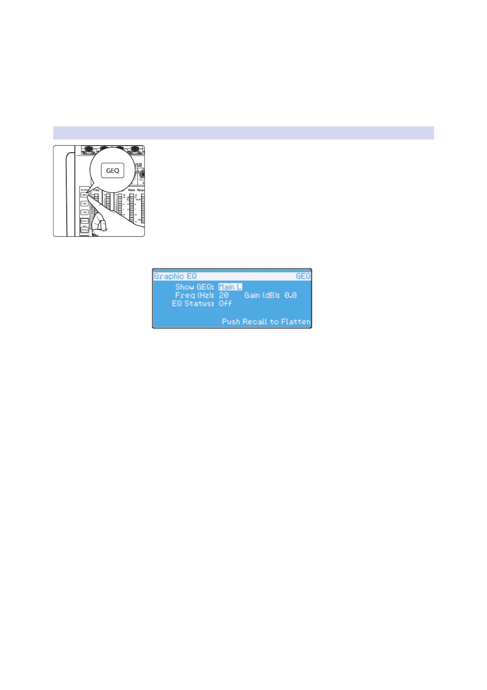
49
6 Digital Effects | Master Control
6.3 Graphic Equalizer
StudioLive™ 16.0.2 USB
Owner’s Manual
you get. With a carefully drawn, smooth curve the StudioLive EQ will have almost
no frequency ripple. The StudioLive EQ is also capable of very sharp notches.
To widen a notch or a bump on a particular band, just bring the adjacent
bands closer to that band‘s gain, and the bandwidth will change accordingly.
Making drastic adjustments too quickly may create an audio artifact as the
new curve is redrawn and crosses over an audio peak. If you are hearing audio
artifacts while setting up the graphic EQ, try creating a smoother curve.
6.3.1 The Graphic EQ Menu and Controls
To turn on and make changes to the graphic EQ, press the GEQ Encoder Mode
button.
The GEQ menu will open in the LCD. When the GEQ page is active, the meters
and encoders of the Fat Channel become the controls for the graphic EQ.
As you touch a knob, you will notice that its band number, frequency, and gain
are displayed in the GEQ menu. The 31 bands range from 20 Hz to 20 kHz. The
frequency for each band is fixed. When the GEQ is first launched, bands 11
through 22 are controlled by encoders 1 through 15/16, respectively. When
Band 10 is selected in the Show Band field in the GEQ menu, the meters will flip,
and encoders 1 through 15/16 will control Bands 1 through 12, respectively.
When Band 23 is selected in the Show Band field in the GEQ menu, the meters
will also flip, and encoders 1 through 15/16 will control bands 23 through 31.
To exit the GEQ, press any of the other Encoder Mode or Master
Control buttons. Each Master Control button will open its respective
menu, and each Encode Mode button will launch the FX menu.
Power User Tip: Select the Show Band field in the GEQ menu and use the Value knob to
scroll through all the bands on the graphic EQ to get a quick overview of the entire curve.
You will notice that all meters have one LED illuminated to display the current
gain position for each band, and the meter for the selected band in the Show
Band field is inverted so that all LEDs are illuminated except for the LED that
displays the current gain position for that band. The band does not have to
be selected in the Show Band field for its encoder to be active. All encoders
are active, so you can make changes to 12 of the 31 bands at one time.

50
6 Digital Effects | Master Control
6.3 Graphic Equalizer
StudioLive™ 16.0.2 USB
Owner’s Manual
6.3.2 Saving and Loading GEQ Presets
Like all other parameters on the StudioLive, graphic
EQ settings can be stored and recalled.
1. If you have created a graphic EQ setting that you would like to save to the GEQ
Preset library, press the Save button in the Fat Channel while that graphic EQ is
active.
2. You will notice that the LCD will display the GEQ Save menu.
3. To begin, use the Value encoder to scroll to an
empty position in the GEQ Preset library.
4. Press the Next button again to navigate to the first letter of the preset
name. Turn the Value encoder clockwise or counter-clockwise to change
the letter. The StudioLive allows you to customize the name with uppercase
and lowercase letters, as well as a selection of numerals and punctuation
marks. You can insert a space by simply pressing the Tap button.
5. Once you are satisfied with your changes, press the Store button.
It will illuminate while the GEQ preset is being written to the StudioLive’s
internal memory. Once the GEQ preset is saved, the Store button will return to its
unlit state.
To load a GEQ preset on the StudioLive:
1. Press the GEQ button.
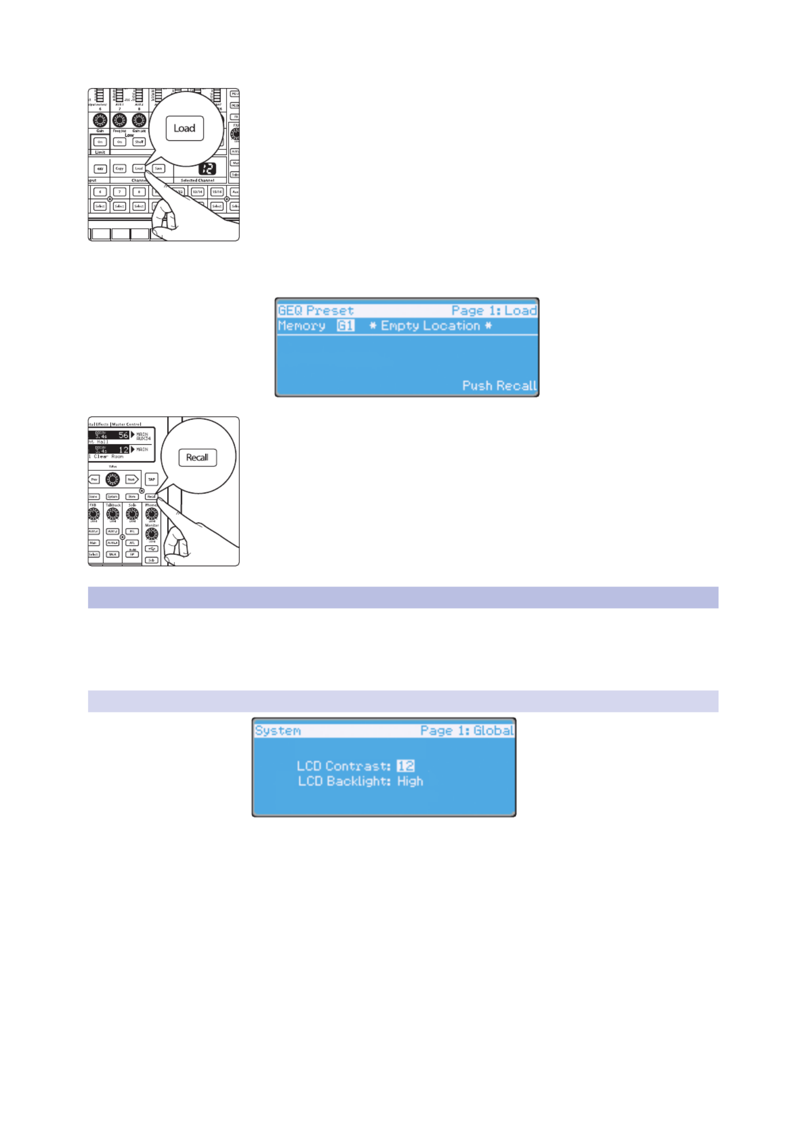
51
6 Digital Effects | Master Control
6.4 System Menu
StudioLive™ 16.0.2 USB
Owner’s Manual
2. From the Fat Channel, press the Load button.
3. You will notice that LCD now displays the GEQ Load menu. Use the
Value encoder to locate the preset you would like to use.
4. Once you have made your selection, press the Recall button. If at any time you
would like to cancel this operation, simply press the Load button again.
6.4 System Menu
In most digital-console manuals, the phrase “System menu” inspires
a sense of dread. However, with the StudioLive, you have nothing
to fear. The System menu on the StudioLive serves just a few simple
functions, most of which have very little to do with mixing a show.
6.4.1 LCD Contrast and LCD Backlight
Press the System button to access the System menu. The first page allows you to
adjust the LCD Contrast and LCD Backlight for optimal viewing in your working
environment. These settings are retained when the unit is powered down.

52
6 Digital Effects | Master Control
6.4 System Menu
StudioLive™ 16.0.2 USB
Owner’s Manual
6.4.2 Aux Send Position
Press the Page Down button to access the Aux Pre Position page. By default, all four
aux buses are set to Pre 1. This places the send of all 16 channels to the aux bus
before the fader, limiter, EQ, and compressor and after the phase-reverse switch,
high-pass filter, and noise gate. The two internal effects buses are set to Post, which
sends each of the channels after all Fat Channel dynamics and EQ and the fader.
From this menu, you can choose between three send positions for each aux mix:
Pre 1: Sends each channel to the aux bus after the
polarity invert, high-pass filter, and gate.
Pre 2: Sends each channel to the aux bus after all Fat Channel parameters (polarity
invert, high-pass filter, gate, compressor, EQ, and limiter) but before the fader.
Post: Sends each channel to the aux bus after all Fat Channel parameters (polarity
invert, high-pass filter, gate, compressor, EQ, and limiter) and after the fader.
Power User Tip: Use the Pre 2 position for headphone and in-ear mixes to give your
performers a polished “studio” sound. This setting should be avoided for floor wedges, as
compression can cause feedback problems!
If you have two aux buses stereo-linked, you only need to set the Pre
position on the Link Master. Remember, the Link Master is the aux that
was selected when the link was created. To determine which aux is the
Link Master, simply select either of the aux buses in the pair. The Link
Master‘s ID will be shown in the Select Channel LED readout.
6.4.3 MIDI Control Mode
The StudioLive 16.0.2 USB can be remotely controlled with a DAW, a MIDI footswitch,
a MIDI keyboard, and an assortment of other MIDI control devices. Pages 3 and
4 of the System menu allow you turn MIDI Control Mode on as well as select on
which MIDI channels the StudioLive will be controlled, as well as which MIDI
Control Change messages will be used. See Section 6.5 for more information
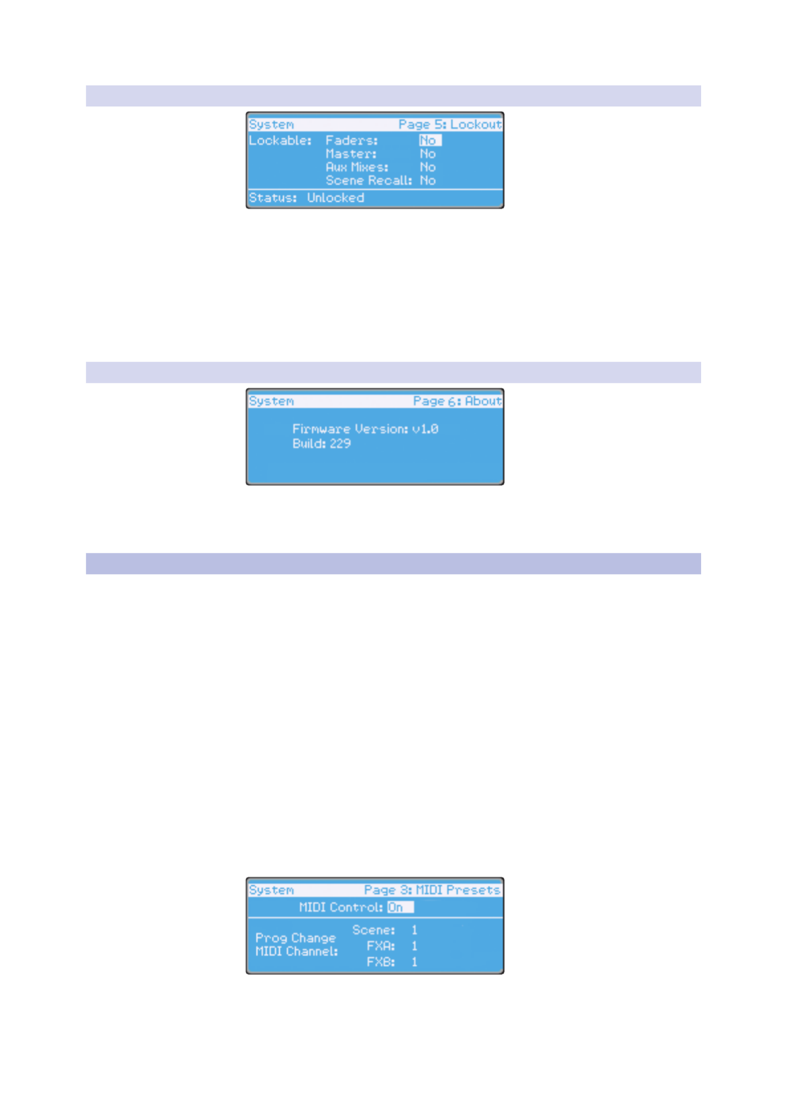
53
6 Digital Effects | Master Control
6.5 Using MIDI Control Mode to Remote-Control StudioLive
StudioLive™ 16.0.2 USB
Owner’s Manual
6.4.4 Lockout Mode
Your StudioLive features a Lockout mode that allows you to create a
password and lock the controls. This is especially useful in situations
where several people will be running sound but only one or two are
knowledgeable enough to set up dynamics processing and the like.
Right out of the box, the StudioLive cannot be locked, so don’t worry about
hitting the wrong button. To enable the Lockout feature, you must first connect
and sync your StudioLive to a computer. Please review the StudioLive 16.0.2
USB Software Library Reference Manual for more information on this feature.
6.4.5 Firmware Version
The last page of the System menu displays the firmware version currently loaded
on your StudioLive. You normally will only view this screen when performing a
system update, to confirm that the new firmware was successfully loaded.
6.5 Using MIDI Control Mode to Remote-Control StudioLive
The StudioLive 16.0.2 USB features a distinctive MIDI Control Mode,
which, once enabled, allows you to remote-control the following
StudioLive parameters from a MIDI device or DAW:
4Scene Recall
4FXA Preset Recall
4FXB Preset Recall
4FXA Assign to Mains
4FXB Assign to Mains
4FXA Output
4FXB Output
4Main Output Level
To enable MIDI Control Mode, navigate to page 3 of the System menu
and set MIDI Control Mode to “On” by turning the value encoder.
This will enable your StudioLive 16.0.2 USB’s MIDI features so that
the mixer can be controlled by any standard MIDI controller.

54
6 Digital Effects | Master Control
6.5 Using MIDI Control Mode to Remote-Control StudioLive
StudioLive™ 16.0.2 USB
Owner’s Manual
Your StudioLive can be controlled with a MIDI controller connected to
the MIDI In jack on the back of it and a MIDI stream transmitted over USB
from a computer. In this section, we will discuss using a hardware MIDI
controller to change the controllable parameters on your StudioLive.
For information on using Studio One Artist or another DAW
to control your StudioLive, please review the StudioLive
16.0.2 USB Software Library Reference Manual.
6.5.1 Understanding MIDI
MIDI stands for “Musical Instrument Digital Interface.” MIDI enables the exchange
of performance information (musical notes, program changes, synth parameters,
and much more) between electronic musical instruments, effects devices,
computers, compatible software applications, and more. It has also been
adopted for a wide range of other applications, both musical and nonmusical.
Before you begin using MIDI Control Mode, there are a few simple
MIDI terms you should understand: MIDI channels, Program
Change messages, and Control Change messages.
4
MIDI Channels. MIDI data is sent and received on 16 channels. This enables
you to send up to 16 discrete messages to a MIDI device at exactly the
same time. Only one MIDI event can be sent at one time on each channel
but multiple messages can be streamed serially (one after the other).
4
Program Change Messages. Program Change messages are sent to a device to
request a “patch” change on a specified MIDI channel. The StudioLive 16.0.2 USB
uses simple Program Change messages to recall Scenes and FX presets.
You can choose on which MIDI channel you would like your StudioLive to receive
these messages. You will want to select a different channel for each one.
4
Control Change Messages. As their name indicates, Control Change
messages are sent to a device to change specific parameter values. A MIDI
Control Change message can be used for many things, including Volume,
Pan, Sustain On/Off, and Modulation. The StudioLive 16.0.2 USB uses Control
Change messages to change the levels of both FX A and FX B and the Main
mix as well as muting and unmuting both buses. You can select to which
Control Change message you would like these parameters to respond.
6.5.2 Recalling Scenes and FX Presets Remotely
To begin, you must first assign unique MIDI channels for FXA, FXB, and
Scene Recall from Page 3 of the System menu. This will allow you to send a
different Program Change message to each of these three preset libraries,
allowing you to navigate through each preset library on its own.
Using the Next and Prev buttons, navigate to each channel field and set a MIDI
channel using the value encoder. You can choose any channel from 1 to 16.
Once you have assigned different MIDI channels for FXA, FXB, and
Scene Recall, you simply need to send a Program Change message
on one of those channels, using your external MIDI controller.
6.5.3 Using Control Change Messages to Control Volume and FX Assignments
Your StudioLive uses CC messages to control Main and FX Output
Volume and FX Assign/Unassign to Mains. Although the MIDI Detailed
Specification assigns particular controls to specified CC message numbers,
you can use any CC message number for these parameters.

55
6 Digital Effects | Master Control
6.5 Using MIDI Control Mode to Remote-Control StudioLive
StudioLive™ 16.0.2 USB
Owner’s Manual
To begin, navigate to page 4 of the System menu and use the value encoder to
assign a unique MIDI channel on which to transmit CC messages to your StudioLive.
Use the Next and Prev buttons to navigate to the FXA, FXB, and Main Output Level
fields and set the Control Change message number you wish to use to control
the output volume for each bus. You can choose any number from 0 to 127.
Next, navigate to the Mute Effects fields and choose a CC message
number to assign/unassign FXA and FXB to the Main bus.
When you are finished, each parameter on this page should have a different
CC message number next to it. With this accomplished, you simply need to
send one of the assigned Control Change messages to the StudioLive on the
designated MIDI channel, using your hardware MIDI controller or DAW.
To set the correct volume for FXA, FXB, and Main output level, your Volume
Control Change messages must include values from 0 to 127. FXA and FXB
Assign to Mains is a simple toggle message, so it is not value-dependent.
The next two sections cover setup instructions for the most popular
MIDI footswitch pedals available when this manual was written. If you
are not using one of these devices, please consult the documentation
that came with your MIDI controller to learn how to send Control
Change and Program Change messages on a given MIDI channel.
6.5.4 Controlling the StudioLive 16.0.2 with a Behringer FCB1010
This tutorial will show you how to quickly configure your StudioLive 16.0.2 USB so
that you can control it with a Behringer FCB1010. The setup configuration detailed
here is just an example; you can customize your own setup using these simple steps.
Each section in this tutorial will focus on a particular setup area.
In order for a FCB1010 to control a StudioLive as described below,
you must complete the steps in each section of the tutorial.
After completing this tutorial, you will have three new
presets on your Behringer FCB1010 pedal:
4
Preset 1 recalls Scene 2 on your StudioLive.
4
Preset 3 recalls “F20: High Ceilings” on FXA on your StudioLive.
4
Preset 6 allows you to control the Main bus assignment for FXA
(effectively muting and unmuting the effect in the Mains) from
Pedal 6 on your FCB1010. You also can control the Main output
volume for your StudioLive using Expression Pedal A.
Setting Up Your StudioLive to be Controlled with MIDI
First set up your StudioLive to be remotely controlled by your footpedal.
In this example, we are setting up the StudioLive to receive Scene changes
on MIDI Channel 1, FXA preset changes on MIDI Channel 2, and FXB preset
changes on MIDI Channel 3. In general, you should set up your StudioLive
so that each library (Scene, FXA, FXB) receives Program Change messages
on its own MIDI channel. The danger of having, for example, Scene recall
and FXA preset recall on the same MIDI channel is that when you change to
Scene 3, you will change the FXA preset to F3: Closet at the same time!
For our example, we also have the output levels and FXA/FXB Assign to Mains on
their own MIDI channels (Channel 4). For your setup, it is perfectly fine to have
these controls share a MIDI channel with one of the recall groups. As previously
mentioned, these parameters are controlled using Control Change messages,

56
6 Digital Effects | Master Control
6.5 Using MIDI Control Mode to Remote-Control StudioLive
StudioLive™ 16.0.2 USB
Owner’s Manual
not Program Change messages, so there is no chance of a conflict—unless
you assign the same CC message to two different StudioLive parameters.
In addition to setting your MIDI Channels and Control Change messages, you will
also need to set MIDI Control Mode to On and make sure the MIDI Source is set to the
StudioLive’s MIDI Input. See the StudioLive 16.0.2 USB Software Reference Manual
for information on controlling your StudioLive via USB using Studio One Artist.
Navigate to Pages 3 and 4 of your StudioLive system menu
and set each page up as shown in these images:
Setting Up Different MIDI Channels on Your FCB1010
Next, you need to configure the pedals on your FCB 1010 to send information
on different MIDI channels. We will use Pedal 1 exclusively for Scene changes,
Pedals 2 and 3 for FXA recall, and Pedals 4 and 5 for FXB recall. You can customize
your pedal to meet your needs; these instructions merely provide a guideline.
1. Boot your FCB1010 into Global configuration mode by holding
the Down pedal while powering on the FCB1010.
PreSonus recommends that you do not use Direct Select mode. When your
FCB1010 boots up, you will see that the green LED above Direct Select is
illuminated. Make sure that the red LED on pedal 10 is not illuminated.
2. Press the Up pedal to select MIDI Function.
3. Press Pedal 1 so that its red LED is flashing.
4. Press the Up Pedal again to select the MIDI channel for Pedal 1.
5. For our purposes, Scene recall is assigned to MIDI Channel
1. Press Pedal 1 so that the LED readout displays “1.”
6. Press the Up Pedal twice to confirm the change and cycle back to MIDI Function.
7. Next, you’ll assign the MIDI channel for FXA Recall.
Press Pedal 2 so that its red LED is flashing.
8. Press the Up Pedal again to select the MIDI channel for Pedal 2.
9. This time, you will select MIDI Channel 2. Press Pedal
2 so that the LED readout displays “2.”
10. Press the Up pedal twice to confirm the change and cycle back to MIDI Function.
11. Repeat steps 8-10 for Pedal 3.
12. Repeat steps 8-11 for Pedals 4 and 5, selecting MIDI Channel 3 for each.

58
6 Digital Effects | Master Control
6.5 Using MIDI Control Mode to Remote-Control StudioLive
StudioLive™ 16.0.2 USB
Owner’s Manual
5. Press the Up pedal to assign the Control Change.
6. Using Expression Pedal A, select CC 64.
7. Press the Up pedal twice to confirm.
8. Press Pedal 8 so that its red LED is flashing.
9. Press the Up pedal to make the Control Change assignment.
10. Using Expression Pedal A, select CC 42.
11. Press the Up pedal once to select the lowest value.
12. Move Expression Pedal A to its lowest position to select 00.
13. Press the Up pedal once to select the highest value.
14. Move Expression Pedal A to its highest position to select 127.
15. Press the Up pedal once to confirm.
16. Press and hold the Down pedal to exit.
Trying Out Presets
4
Preset 1 recalls Scene 2 on your StudioLive.
4
Preset 3 recalls “F20: High Ceilings” on FXA on your StudioLive.
4
Preset 6 allows you to control the Main bus assignment for FXA
(effectively muting and unmuting the effect in the Mains) from
Pedal 6 on your FCB1010. You also can control the Main output
volume for your StudioLive using Expression Pedal A.
6.5.5 Controlling the StudioLive 16.0.2 with a Roland FC-300
Roland FC-300 Patch Mode offers many flexible ways for you to control your
StudioLive 16.0.2 USB. Each patch allows you to assign multiple MIDI controls
to any of the four control pedals. In this example, we will create a patch that
instantly recalls a Scene, and we will assign to other pedals an FXA preset recall
and the FXA assignment to the Main bus. Finally, one expression pedal will control
the FXA output level, while the other will control the Main output volume.
This tutorial will show you how to quickly configure your StudioLive 16.0.2 USB so
that you can control it with a Roland FC-300. The setup configuration detailed here
is just an example; you can customize your own setup using these simple steps.
Each section in this tutorial will focus on a particular setup area. In order for a
FC-300 to control a StudioLive as described below, you must complete the steps
in each section of this tutorial. Once you have completed the tutorial, you will
have a new patch on your FC-300 that controls your StudioLive as follows:
4
CTL1: Recall Preset F10:Concrete Floors on FXA
4
CTL2: Assign/Unassign FXA to Main bus
4
Expression Pedal 1: FXA Output level
4
Expression Pedal 2: Main Output level
Setting Up the StudioLive to be Controlled with MIDI
You must first set up your StudioLive to be remotely controlled by the footpedal.
In this example, we are setting up the StudioLive to receive Scene changes
on MIDI Channel 1, FXA preset changes on MIDI Channel 2, and FXB preset
changes on MIDI Channel 3. In general, you should set up your StudioLive so
that each library (Scene, FXA, FXB) is receiving Program Change messages
on its own MIDI channel. The danger of having, for example, Scene Recall
and FXA preset recall on the same MIDI channel is that when you change to

59
6 Digital Effects | Master Control
6.5 Using MIDI Control Mode to Remote-Control StudioLive
StudioLive™ 16.0.2 USB
Owner’s Manual
Scene 3, you will change the FXA preset to F3: Closet at the same time!
For our example, we also have the output levels and FXA/FXB Assign to Mains
on their own MIDI channel (Channel 4). For your setup, it is perfectly fine to have
these control share a MIDI channel with one of the recall groups. As previously
mentioned, these parameters are controlled using Control Change messages,
not Program Change messages, so there is no chance of a conflict—unless
you assign the same CC message to two different StudioLive parameters.
Besides setting your MIDI channels and Control Change messages,
you will also need to set MIDI Control Mode to On. Please review the
StudioLive 16.0.2 USB Software Library Reference Manual for information
on how to control your StudioLive via USB using Studio One Artist.
Before setting up your FC-300, you must set up your StudioLive for this example.
Navigate to Pages 3 and 4 of your StudioLive system menu
and set each page up as shown in these images:
Creating a New Patch on the Roland FC-300
Now that your StudioLive is set up to communicate with the Roland FC-
300, you will need to create a new patch. Remember, you must follow
all of the steps in this tutorial to control your StudioLive as previously
described. At the end of this tutorial, we’ll discuss how to name and
save your new patch so you can use it again in the future.
Instant Scene Recall
1. Press the Mode button until the Patch Mode LED is illuminated.
2. Making sure the red LED is illuminated on the
first row of pedals, depress Pedal 1/6.
3. Press the right Parameter button. The LCD will display “PATCH: On MIDI.”
4. Press the Write button so that the LCD displays “Edit MIDI.”
5. Press the Write button again. You will see “001: ----- -----.“
6. Press the right Parameter button.
7. Press the Value Up button so that the LCD displays “001:PC CH#01 PC#001.”
8. The first field defaults to Program Change (“PC”). This is how the
StudioLive recalls Scenes, so you can leave this field as it is.
9. Use the right Parameter button to move to the next field: MIDI channel number.
10. Set the MIDI channel to 1.
11. Use the right Parameter button to move to the next field: Program Change
number. The number you enter will determine which Scene will be recalled.

60
6 Digital Effects | Master Control
6.5 Using MIDI Control Mode to Remote-Control StudioLive
StudioLive™ 16.0.2 USB
Owner’s Manual
12. Use the Value Up button to set the Program Change number to 002.
13. Press the Exit button twice and continue to FXA Preset Recall.
FXA Preset Recall
Next we will set CTL Pedal 1 to recall a preset on FXA. Press the right
Parameter button until the LCD displays “CTL1: On MIDI.”
1. Press the Write button so that the LCD displays “Edit MIDI.”
2. Press the Write button again. You will see “001: ----- -----.“
3. Press the right Parameter button.
4. Press the Value Up button so that the LCD displays “001:PC CH#01 PC#001.”
5. The first field defaults to Program Change (“PC”). This is how the
StudioLive recalls FX presets, so you can leave this field as it is.
6. Use the right Parameter button to move to the next field: MIDI channel number.
7. Set the MIDI channel to 2.
8. Use the right Parameter button to move to the next field: Program Change
number. The number you enter will determine which FX Preset will be recalled.
9. Use the Value Up button to set the Program Change number to 10.
10. Press the Exit button twice and continue to FXA Assign/Unassign to Mains.
FXA Assign/Unassign to Mains
Next, we will set CTL Pedal 2 to control the Main assignment (“mute”) for FXA.
1. Press the right Parameter button until the LCD reads “CTL2: Assign.”
2. The curser should be on the CH# Tx field. Press the Value
Down button until the MIDI channel value is “04.”
3. Use the right Parameter button to navigate to the CC# field.
4. Use the Value Up and Down buttons to set the Control Change number to 64.
5. Continue to FXA and Main Bus Output Levels.
FXA and Main Bus Output Levels
1. Press the right Parameter button until the LCD reads “EXP1: Assign.”
2. Use the right Parameter button to navigate to the CH# Tx field and
press the Value Down button until the MIDI channel value is “04.”
3. Use the right Parameter button to navigate to the CC# field.
4. Use the Value Up and Down buttons to set the Control Change number to 40.
5. Press the right Parameter button until the LCD reads “EXP2: Assign.”
6. Use the right Parameter button to navigate to the CH# Tx field and
press the Value Down button until the MIDI channels value is “04.”
7. Use the right Parameter button to navigate to the CC# field.
8. Use the Value Up and Down buttons to set the Control Change number to 42.
Continue to Naming and Saving Your Patch.

61
6 Digital Effects | Master Control
6.5 Using MIDI Control Mode to Remote-Control StudioLive
StudioLive™ 16.0.2 USB
Owner’s Manual
Naming and Saving Your Patch
1. Press the right Parameter button until the LCD reads “Patch Name.”
2. Use the Value Up and Down buttons and left/right Parameter
buttons to enter a name (such as “My Preset”).
3. Press the Exit button. You will now be on the Main screen of the LCD.
4. Press the Write button so that the LCD displays “Write to [WRITE] 01:”
5. In this example, we will save to patch-library position 01
but you can also use the Value buttons to scroll to an empty
patch position. Press the Write button again to store.
6. Press the Write button again to confirm.
Recalling StudioLive Scenes
Making sure the red LED is illuminated on the first row of pedals,
depress Pedal 1/6. You will see that Scene 2 has been recalled on your
StudioLive. You are now ready to control your StudioLive as follows:
4
CTL1: Recall Preset F10: Concrete Floors on FXA
4
CTL2: Assign/Unassign FXA to Main bus
4
Expression Pedal 1: FXA Output level
4
Expression Pedal 2: Main Output level
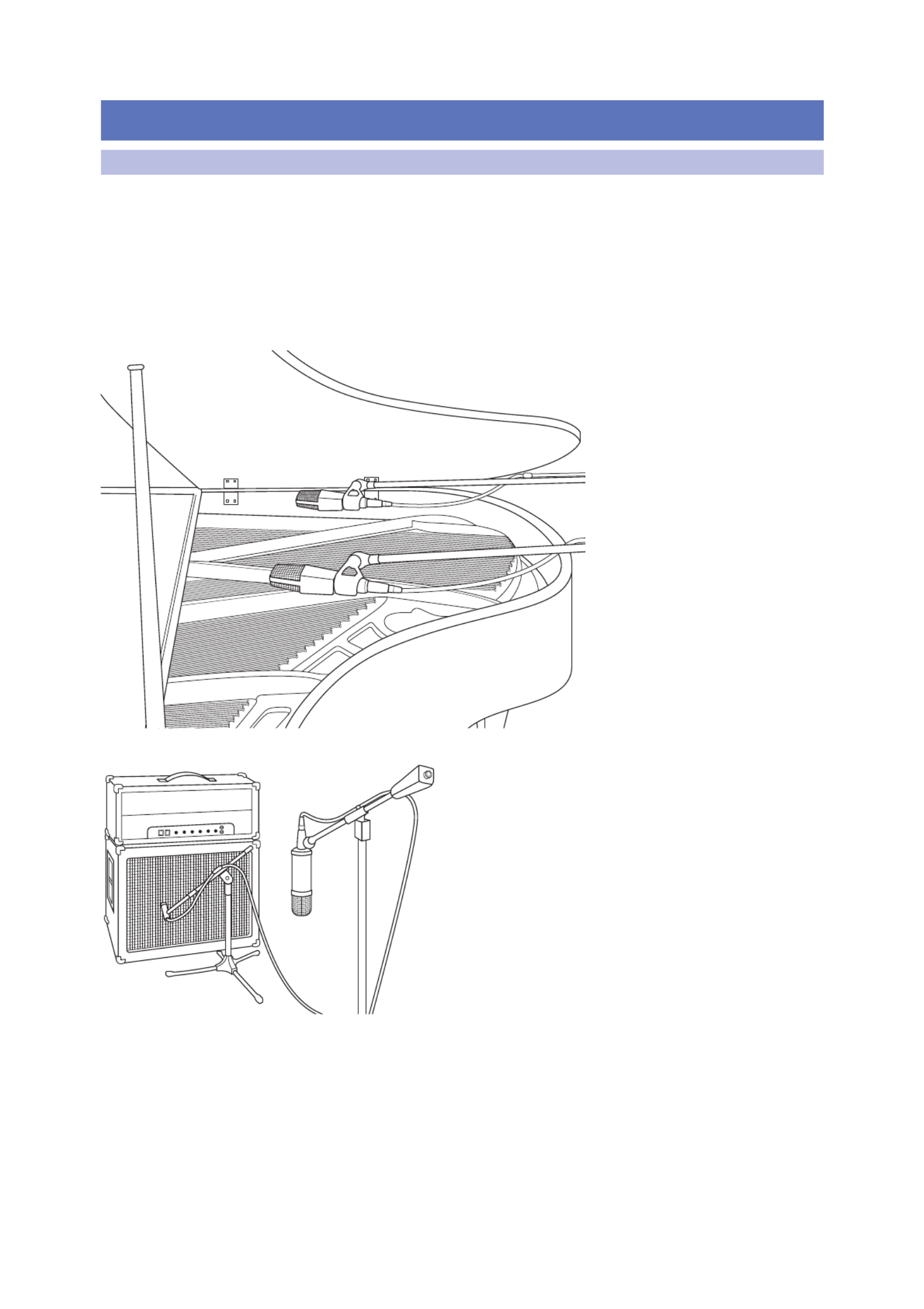
62
7 Resources
7.1 Stereo Microphone Placement
StudioLive™ 16.0.2 USB
Owner’s Manual
7 Resources
7.1 Stereo Microphone Placement
The following are a few recording applications to help you get started with your
StudioLive. These are by no means the only ways to record these instruments.
Microphone selection and placement is an art. For more information, visit
your library or local bookstore, as there are many books and magazines
about recording techniques. The Internet is also a great source of recording
information, as are instructional videos. Some of these microphone-placement
suggestions can be used in live applications, as well as for studio recording.
Grand Piano
Place one microphone above the
high strings and one microphone
above the low strings. Experiment
with distance (the farther back the
more room you will capture). This
technique can be used for live and
studio applications.
Electric Guitar
Place a dynamic microphone an inch or two away
from the speaker of the guitar amplifier. Experiment
with exact location. If you are recording an amp with
multiple speakers, experiment with each one to see if
one sounds better than the others. Place a condenser
microphone approximately six feet away, pointed at the
amp. Experiment with distance. Also experiment with
inverting the phase of the room microphone to check
for phase cancellation and reinforcement. (Select the
“fuller”-sounding position.) To use this technique in a live
application, omit the condenser microphone.

63
7 Resources
7.1 Stereo Microphone Placement
StudioLive™ 16.0.2 USB
Owner’s Manual
Acoustic Guitar
Point a small-diaphragm condenser microphone at the 12th
fret, approximately 8 inches away. Point a large-diaphragm
condenser microphone at the bridge of the guitar,
approximately 12 inches from the guitar. Experiment with
distances and microphone placement. Another popular
method is using an XY microphone placement with two
small-diaphragm condenser microphones. (See drum-
overheads picture on the next page.)
Bass Guitar (Direct and Speaker)
Plug the electric bass guitar into a passive direct box. Connect the
instrument output from the passive direct box to a bass amplifier. Place a
dynamic microphone an inch or two away from the speaker and connect
it to a StudioLive microphone input. Connect the line output from the
passive direct box to a line input on a different channel of the StudioLive.
For recording, place these signals on separate tracks. During mixing, you
can blend the direct and amplifier signal to taste. This technique can also
be used in live applications.

64
7 Resources
7.1 Stereo Microphone Placement
StudioLive™ 16.0.2 USB
Owner’s Manual
Drum Overheads (XY example)
Place two small-diaphragm
condenser microphones on an XY
stereo-microphone holder (bar).
Position the microphones so that
each one is at a 45-degree angle,
pointed down at the drum kit,
approximately 7 or 8 feet above the
floor or drum riser. Experiment with
height. This technique can be used in
live applications as well.
Snare Drum (top and bottom)
Point a dynamic microphone at the center of the snare, making sure it is placed so
that the drummer will not hit it. Place a small-diaphragm condenser microphone
under the drum, pointed at the snares. Experiment with the placement of
both microphones. Also experiment with inverting the phase of the bottom
microphone. This technique can be used in live applications.
.
Specyfikacje produktu
| Marka: | PreSonus |
| Kategoria: | Konsola miksująca |
| Model: | StudioLive 16.0.2 USB |
Potrzebujesz pomocy?
Jeśli potrzebujesz pomocy z PreSonus StudioLive 16.0.2 USB, zadaj pytanie poniżej, a inni użytkownicy Ci odpowiedzą
Instrukcje Konsola miksująca PreSonus

7 Września 2024
2 Września 2024
31 Sierpnia 2024
26 Sierpnia 2024
26 Sierpnia 2024
26 Sierpnia 2024
26 Sierpnia 2024
26 Sierpnia 2024
26 Sierpnia 2024
25 Sierpnia 2024
Instrukcje Konsola miksująca
- Konsola miksująca Sony
- Konsola miksująca Yamaha
- Konsola miksująca Electrolux
- Konsola miksująca DeLonghi
- Konsola miksująca Caso
- Konsola miksująca Gorenje
- Konsola miksująca BeamZ
- Konsola miksująca Braun
- Konsola miksująca Pioneer
- Konsola miksująca Philips
- Konsola miksująca SilverCrest
- Konsola miksująca Technics
- Konsola miksująca Bosch
- Konsola miksująca Dash
- Konsola miksująca JBL
- Konsola miksująca Roland
- Konsola miksująca Scott
- Konsola miksująca Bose
- Konsola miksująca Severin
- Konsola miksująca Behringer
- Konsola miksująca Nedis
- Konsola miksująca Allen & Heath
- Konsola miksująca Boss
- Konsola miksująca Black & Decker
- Konsola miksująca Adler
- Konsola miksująca Marquant
- Konsola miksująca Domo
- Konsola miksująca Taurus
- Konsola miksująca ATen
- Konsola miksująca Siemens
- Konsola miksująca Hyundai
- Konsola miksująca Mesko
- Konsola miksująca DAP-Audio
- Konsola miksująca Concept
- Konsola miksująca Heritage Audio
- Konsola miksująca Shure
- Konsola miksująca Denon
- Konsola miksująca Kenwood
- Konsola miksująca Røde
- Konsola miksująca Zelmer
- Konsola miksująca Cuisinart
- Konsola miksująca Krups
- Konsola miksująca Bomann
- Konsola miksująca Moulinex
- Konsola miksująca Emerio
- Konsola miksująca Alesis
- Konsola miksująca Melissa
- Konsola miksująca Auna
- Konsola miksująca LD Systems
- Konsola miksująca Stirling
- Konsola miksująca Philco
- Konsola miksująca Instant
- Konsola miksująca Fagor
- Konsola miksująca Redmond
- Konsola miksująca Koenic
- Konsola miksująca Velleman
- Konsola miksująca Korg
- Konsola miksująca DataVideo
- Konsola miksująca Wharfedale
- Konsola miksująca Arendo
- Konsola miksująca Pyle
- Konsola miksująca Zoom
- Konsola miksująca Numark
- Konsola miksująca KitchenAid
- Konsola miksująca Camry
- Konsola miksująca Speco Technologies
- Konsola miksująca Showtec
- Konsola miksująca Samson
- Konsola miksująca TriStar
- Konsola miksująca Ibiza Sound
- Konsola miksująca Vonyx
- Konsola miksująca Bogen
- Konsola miksująca Exquisit
- Konsola miksująca Alto
- Konsola miksująca Peavey
- Konsola miksująca ION
- Konsola miksująca ART
- Konsola miksująca Hanseatic
- Konsola miksująca RCF
- Konsola miksująca Bifinett
- Konsola miksująca Rolls
- Konsola miksująca Audio-Technica
- Konsola miksująca TC Helicon
- Konsola miksująca Soundcraft
- Konsola miksująca AKAI
- Konsola miksująca Clatronic
- Konsola miksująca Klark Teknik
- Konsola miksująca Proel
- Konsola miksująca Inventum
- Konsola miksująca Ariete
- Konsola miksująca DBX
- Konsola miksująca Sunbeam
- Konsola miksująca Omnitronic
- Konsola miksująca Solac
- Konsola miksująca Mackie
- Konsola miksująca Lindell Audio
- Konsola miksująca Comfee
- Konsola miksująca Dynacord
- Konsola miksująca Ashly
- Konsola miksująca Inter-M
- Konsola miksująca Atlas Sound
- Konsola miksująca Gemini
- Konsola miksująca Martin
- Konsola miksująca Radial Engineering
- Konsola miksująca Hobart
- Konsola miksująca Power Dynamics
- Konsola miksująca Alecto
- Konsola miksująca Kalorik
- Konsola miksująca TOA
- Konsola miksująca Monacor
- Konsola miksująca HQ Power
- Konsola miksująca Tascam
- Konsola miksująca SPL
- Konsola miksująca Alfatron
- Konsola miksująca Reloop
- Konsola miksująca Chandler
- Konsola miksująca Midas
- Konsola miksująca Dangerous Music
- Konsola miksująca Alpina
- Konsola miksująca Allen-Heath
- Konsola miksująca Alto Professional
- Konsola miksująca American Audio
- Konsola miksująca ADB
- Konsola miksująca Korona
- Konsola miksująca Nordland
- Konsola miksująca Fritel
- Konsola miksująca Steren
- Konsola miksująca Envivo
- Konsola miksująca AV:link
- Konsola miksująca Pyle Pro
- Konsola miksująca Valcom
- Konsola miksująca Blaze
- Konsola miksująca IDance
- Konsola miksująca Primo
- Konsola miksująca QTX
- Konsola miksująca Konig
- Konsola miksująca RDL
- Konsola miksująca Fredenstein
- Konsola miksująca Swissonic
- Konsola miksująca Team
- Konsola miksująca Aviom
- Konsola miksująca QSC
- Konsola miksująca CaterChef
- Konsola miksująca Roadstar
- Konsola miksująca Golden Age Project
- Konsola miksująca Efbe-schott
- Konsola miksująca Apart
- Konsola miksująca Turmix
- Konsola miksująca Russound
- Konsola miksująca Skytec
- Konsola miksująca Waves
- Konsola miksująca Home Electric
- Konsola miksująca Monoprice
- Konsola miksująca Yorkville
- Konsola miksująca Elysia
- Konsola miksująca Solid State Logic
- Konsola miksująca OSD Audio
- Konsola miksująca Adastra
- Konsola miksująca Zolid
- Konsola miksująca Stanton
- Konsola miksująca TeachLogic
- Konsola miksująca Citronic
- Konsola miksująca Warm Audio
- Konsola miksująca Audiophony
- Konsola miksująca JB Systems
- Konsola miksująca Manley
- Konsola miksująca Extron
- Konsola miksująca NutriBullet
- Konsola miksująca Venga
- Konsola miksująca Crown
- Konsola miksująca Dateq
- Konsola miksująca Avid
- Konsola miksująca M-GAME
- Konsola miksująca Ecler
- Konsola miksująca Icon
- Konsola miksująca Stagg
- Konsola miksująca Santos
- Konsola miksująca Fun Generation
- Konsola miksująca ANT
- Konsola miksująca IMG Stage Line
- Konsola miksująca Rane
- Konsola miksująca CAD Audio
- Konsola miksująca Phonic
- Konsola miksująca Koda
- Konsola miksująca JTS
- Konsola miksująca RCS
- Konsola miksująca DAP
- Konsola miksująca Trident
- Konsola miksująca Audibax
- Konsola miksująca IMG Stageline
- Konsola miksująca The T.mix
- Konsola miksująca Cloud
- Konsola miksująca Glemm
- Konsola miksująca DNA
- Konsola miksująca Analogue Solutions
- Konsola miksująca Auna Pro
Najnowsze instrukcje dla Konsola miksująca
9 Kwietnia 2025
6 Kwietnia 2025
3 Kwietnia 2025
3 Kwietnia 2025
3 Kwietnia 2025
2 Kwietnia 2025
2 Kwietnia 2025
31 Marca 2025
31 Marca 2025
30 Marca 2025