Instrukcja obsługi Nissan Murano (2010)
Nissan
Automatyczny
Murano (2010)
Przeczytaj poniżej 📖 instrukcję obsługi w języku polskim dla Nissan Murano (2010) (425 stron) w kategorii Automatyczny. Ta instrukcja była pomocna dla 4 osób i została oceniona przez 2 użytkowników na średnio 4.5 gwiazdek
Strona 1/425


Black plate (2,1)
Model "Z51-D" EDITED: 2009/ 7/ 31
Welcome to the growing family of new NISSAN
owners. This vehicle is delivered to you with
confidence. It was produced using the latest
techniques and strict quality control.
This manual was prepared to help you under-
stand the operation and maintenance of your
vehicle so that you may enjoy many miles of
driving pleasure. Please read through this
manual before operating your vehicle.
A separate Warranty Information Booklet
explains details about the warranties cov-
ering your vehicle. The NISSAN Service
and Maintenance Guide explains details
about maintaining and servicing your ve-
hicle. Additionally, a separate Customer
Care/Lemon Law Booklet (U.S. only) will
explain how to resolve any concerns you
may have with your vehicle, as well as
clarify your rights under your state’s lemon
law.
Your NISSAN dealer knows your vehicle best.
When you require any service or have any
questions, we will be glad to assist you with the
extensive resources available to us.
READ FIRST — THEN DRIVE SAFELY
Before driving your vehicle, read your Owner’s
Manual carefully. This will ensure familiarity with
controls and maintenance requirements, assist-
ing you in the safe operation of your vehicle.
WARNING
IMPORTANT SAFETY INFORMA-
TION REMINDERS FOR SAFETY!
Follow these important driving rules to
help ensure a safe and comfortable trip
for you and your passengers!
.NEVER drive under the influence of
alcohol or drugs.
.ALWAYS observe posted speed lim-
its and never drive too fast for
conditions.
.ALWAYS give your full attention to
driving and avoid using vehicle
features or taking other actions that
could distract you.
.ALWAYS use your seat belts and
appropriate child restraint systems.
Pre-teen children should be seated
in the rear seat.
.ALWAYS provide information about
the proper use of vehicle safety
features to all occupants of the
vehicle.
.ALWAYS review this Owner’s Man-
ual for important safety information.
ON-PAVEMENT AND OFF-ROAD
DRIVING
This vehicle will handle and maneuver
differently from an ordinary passenger
car because it has a higher center of
gravity for off-road use. As with other
vehicles with features of this type, failure
to operate this vehicle correctly may
result in loss of control or an accident.
Be sure to read “On-pavement and off-
road driving precautions”, “Avoiding colli-
sion and rollover” and “Driving safety
precautions” in the “5. Starting and driv-
ing” section of this manual.
MODIFICATION OF YOUR VEHICLE
This vehicle should not be modified.
Modification could affect its performance,
safety or durability, and may even violate
governmental regulations. In addition,
damage or performance problems result-
ing from modification may not be covered
under NISSAN warranties.
WHEN READING THE MANUAL
This manual includes information for all
options available on this model. Therefore,
you may find some information that does
not apply to your vehicle.
Foreword

Black plate (3,1)
Model "Z51-D" EDITED: 2009/ 8/ 3
All information, specifications and illustrations in
this manual are those in effect at the time of
printing. NISSAN reserves the right to change
specifications or design at any time without
notice.
IMPORTANT INFORMATION ABOUT
THIS MANUAL
You will see various symbols in this manual. They
are used in the following ways:
WARNING
This is used to indicate the presence of
a hazard that could cause death or
serious personal injury. To avoid or
reduce the risk, the procedures must
be followed precisely.
CAUTION
This is used to indicate the presence of
a hazard that could cause minor or
moderate personal injury or damage to
your vehicle. To avoid or reduce the risk,
the procedures must be followed care-
fully.
SIC0697
If you see the symbol above, it means “Do not
do this” or “Do not let this happen”.
If you see a symbol similar to those above in an
illustration, it means the arrow points to the front
of the vehicle.
Arrows in an illustration that are similar to those
above indicate movement or action.
Arrows in an illustration that are similar to those
above call attention to an item in the illustration.
CALIFORNIA PROPOSITION 65
WARNING
WARNING
Engine exhaust, some of its constitu-
ents, and certain vehicle components
contain or emit chemicals known to the
State of California to cause cancer and
birth defects or other reproductive
harm. In addition, certain fluids con-
tained in vehicles and certain products
of component wear contain or emit
chemicals known to the State of Cali-
fornia to cause cancer and birth defects
or other reproductive harm.
CALIFORNIA PERCHLORATE ADVI-
SORY
Some vehicle parts, such as lithium bat-
teries, may contain perchlorate material.
The following advisory is provided: “Per-
chlorate Material - special handling may
apply, See www.dtsc.ca.gov/
hazardouswaste/perchlorate.”

Black plate (4,1)
Model "Z51-D" EDITED: 2009/ 8/ 3
BLUETOOTH®is a trademark
owned by Bluetooth SIG, Inc.,
U.S.A.
Gracenote®is a registered tra-
demark of Gracenote, Inc. The
Gracenote logo and logo type,
and the “Powered by Gracenote”
logo are trademarks of Grace-
note.
XM Radio®requires a subscrip-
tion, sold separately after the first
90 days. It is not available in
Alaska, Hawaii or Guam. For
more information, visit
www.xmradio.com.
*
C2009 NISSAN MOTOR CO., LTD.
All rights reserved. No part of this Owner’s
Manual may be reproduced or stored in a
retrieval system, or transmitted in any form, or
by any means, electronic, mechanical, photo-
copying, recording or otherwise, without the
prior written permission of Nissan Motor Co.,
Ltd.
Black plate (5,1)
Model "Z51-D" EDITED: 2009/ 8/ 3
NISSAN CARES ...
Both NISSAN and your NISSAN dealer are dedicated to serving all your automotive needs. Your satisfaction with your vehicle and your NISSAN dealer are
our primary concerns. Your NISSAN dealer is always available to assist you with all your automobile sales and service needs.
We appreciate your interest in NISSAN and thank you for buying a quality NISSAN vehicle.
However, if there is something that your
NISSAN dealer cannot assist you with or you
would like to provide NISSAN directly with
comments or questions, please contact the
NISSAN Consumer Affairs Department using
our toll-free number:
For U.S. customers
1-800-NISSAN-1
(1-800-647-7261)
For Canadian customers
1-800-387-0122
The Consumer Affairs Department will ask for
the following information:
— Your name, address, and telephone number
— Vehicle identification number (attached to
the top of the instrument panel on the
driver’s side)
— Date of purchase
— Current odometer reading
— Your NISSAN dealer’s name
— Your comments or questions
OR
You can write to NISSAN with the information at:
For U.S. customers
Nissan North America, Inc.
Consumer Affairs Department
P.O. Box 685003
Franklin, TN 37068-5003
For Canadian customers
Nissan Canada Inc.
5290 Orbitor Drive
Mississauga, Ontario L4W 4Z5
NISSAN CUSTOMER CARE
PROGRAM

Black plate (1,1)
Table of
Contents
Model "Z51-D" Edited: 2009/ 8/ 3
Illustrated table of contents 0
Safety — Seats, seat belts and supplemental
restraint system 1
Instruments and controls 2
Pre-driving checks and adjustments 3
Monitor, heater, air conditioner, audio, phone and
voice recognition systems 4
Starting and driving 5
In case of emergency 6
Appearance and care 7
Maintenance and do-it-yourself 8
Technical and consumer information 9
Index 10

Black plate (1,1)
Seats, seat belts and Supplemental Restraint
System (SRS) ................................................... 0-2
Exterior front ..................................................... 0-3
Exterior rear ...................................................... 0-5
Passenger compartment ...................................... 0-6
Instrument panel ................................................ 0-7
Meters and gauges............................................. 0-9
Engine compartment ......................................... 0-10
VQ35DE engine .......................................... 0-10
Warning and indicator lights ............................... 0-11
0 Illustrated table of contents
Model "Z51-D" EDITED: 2009/ 8/ 3

Black plate (4,1)
Model "Z51-D" EDITED: 2009/ 8/ 3
SSI0372B
1. Rear center seat belt (Page 1-22)
2. Adjustable headrest (P.1-12)
3. Seat belts (P.1-15)
4. Armrest (P.1-14)
5. Head restraints (P.1-9)
— Front-seat Active Head Restraints (P.1-11)
6. Roof-mounted curtain side-impact and rollover
supplemental air bags (P.1-45)
7. Supplemental front-impact air bags (P.1-45)
8. Child restraint anchor points (for top tether strap
child restraint) (P.1-29)
9. LATCH (Lower Anchors and Tethers for CHildren)
system (P.1-28)
10. Rear seats (P.1-6)
— Child restraints (P.1-26)
11. Front seat-mounted side-impact supplemental air
bags (P.1-45)
12. Seat belt pretensioner (P.1-57)
13. Front seats (P.1-3)
14. Occupant classification sensor (pattern sensor)
— Advanced Air Bag System (P.1-51)
SEATS, SEAT BELTS AND
SUPPLEMENTAL RESTRAINT
SYSTEM (SRS)
0-2 Illustrated table of contents
Black plate (5,1)
Model "Z51-D" EDITED: 2009/ 8/ 3
SSI0373
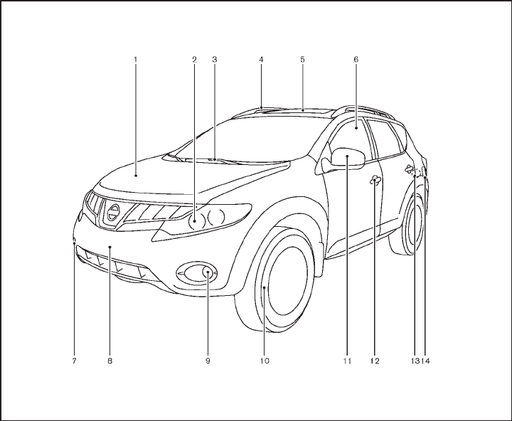
1. Hood (P.3-18)
2. Headlight and turn signal lights
— Switch operation (P.2-32)
— Bulb replacement (P.8-25)
3. Windshield wiper and washer
— Switch operation (P.2-28)
— Rain-sensing auto wiper system*
(P.2-29)
— Blade replacement (P.8-17)
— Window washer fluid (P.8-12)
4. Roof rack (rail)* (P.2-47)
5. Moonroof* (P.2-51)
6. Power windows (P.2-48)
7. Recovery hook (P.6-15)
8. License plate installation (P.9-11)
9. Fog lights*
— Switch operation (P.2-35)
— Bulb replacement (P.8-27)
10. Tires
— Wheel and tires (P.8-30, P.9-7)
— Flat tire (6-2)
— Tire Pressure Monitoring System (TPMS)
(P.2-12, P.5-3)
11. Outside mirrors (P.3-29)
12. Doors
— Keys (P.3-2)
— Door locks (P.3-4)
— Intelligent Key system (P.3-7)
— Security system (P.2-25)
13. Child safety rear door lock (P.3-7)
EXTERIOR FRONT
Illustrated table of contents 0-3
Black plate (6,1)
Model "Z51-D" EDITED: 2009/ 8/ 3
14. Fuel-filler door
— Operation (P.3-23)
— Fuel recommendation (P.9-3)
*: if so equipped
0-4 Illustrated table of contents
Black plate (7,1)
Model "Z51-D" EDITED: 2009/ 8/ 3
SSI0374
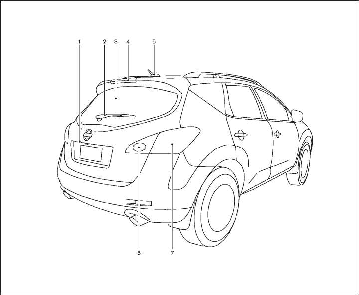
1. Lift gate (P.3-19)
— Remote keyless entry system (P.3-15)
— Intelligent Key system (P.3-7)
2. Rear window wiper and washer
— Switch operation (P.2-30)
— Window washer fluid (P.8-12)
3. Rear window defroster (P.2-31)
4. High-mounted stop light
— Bulb replacement (P.8-27)
5. Antenna (P.4-62)
— Satellite radio antenna* (P.4-32)
6. Back-up light
— Bulb replacement (P.8-27)
7. Rear combination light
— Bulb replacement (P.8-27)
*: if so equipped
EXTERIOR REAR
Illustrated table of contents 0-5

Black plate (8,1)
Model "Z51-D" EDITED: 2009/ 8/ 3
SSI0636
1. Cargo cover* (P.2-45)
2. Rear personal light (P.2-53)
3. Coat hooks (P.2-48)
4. Mobile Entertainment System (MES)*
— Flip-down screen (P.4-64)
— Digital Versatile Disc (DVD) player (P.4-63)
— DVD remote controller (P.4-67)
— Headphones (P.4-66)
5. Door armrest
— Power window switch (P.2-48)
— Power door lock switch (P.3-6)
— Outside mirror remote control switch (P.3-29)
6. Sun visors (P.3-26)
7. Moonroof* (P.2-51)
8. Front map lights (P.2-53)
9. Mood light (P.2-54)
10. Sunglasses holder (P.2-42)
11. Inside rearview mirror (P.3-27)
— Anti-glare adjustment* (P.3-28)
— HomeLink®universal transceiver* (P.2-55)
— Compass* (P.2-7)
12. Cargo area
— Storages (P.2-45)
— Luggage hooks (P.2-46)
— Cargo light (P.2-55)
— Spare tire (P.6-3)
13. Rear cup holders (P.2-41)
14. Heated seat switch (rear)* (P.2-37)
15. Console box - rear (P.2-43)
16. Auxiliary input jack* (P.4-48)
17. Console box (P.2-43)
— Power outlet* (P.2-39)
18. Front cup holders (P.2-41)
19. Storage box (P.2-44) or Cigarette lighter/Ashtray
(P.2-40)
*: if so equipped
PASSENGER COMPARTMENT
0-6 Illustrated table of contents

Black plate (9,1)
Model "Z51-D" EDITED: 2009/ 8/ 3
SSI0627
1. Side ventilator (P.4-25)
2. Power lift gate switch* (P.3-19)
3. Headlight, fog light* and turn signal switch
(P.2-32)
4. Fuel-filler door opener switch (P.3-23)
5. Steering-wheel-mounted controls (left side)*
— Audio control* (P.4-61)
— Bluetooth®Hands-Free Phone System control*
(P.4-75)
6. Meters and gauges (P.2-4)
7. Steering wheel
— Horn (P.2-36)
— Driver supplemental air bag (P.1-45)
— Power steering system (P.5-25)
8. Steering-wheel-mounted controls (right side)
— Cruise control switches (P.5-18)
9. Wiper and washer switch (P.2-28)
10. Push-button ignition switch (P.5-9)
11. Center ventilator (P.4-25)
12. Center display (P.4-2)/Center color display*
(P.4-2)/Navigation system**
13. Heater/air conditioner or
Center multi-function control panel*
— Navigation system**
— Vehicle information and setting buttons (P.4-8)
— Bluetooth®Hands-Free Phone System (P.4-75)
— Audio system (P.4-31)
14. Hazard warning flasher switch (P.2-36)
15. Front passenger supplemental air bag (P.1-45)
16. Vehicle Dynamic Control (VDC) OFF switch
(P.2-39, 5-27)
17. Hood release handle (P.3-18)
18. Power lift gate main switch (P.3-19)
19. Power seatback switch* (P.1-6)
20. Fuse box cover (P.8-21)
21. Parking brake (P.5-17)
22. Tilting telescopic steering wheel lever or switch
(P.3-25)
23. Intelligent Key port (P.5-11)
INSTRUMENT PANEL
Illustrated table of contents 0-7
Black plate (10,1)
Model "Z51-D" EDITED: 2009/ 8/ 3
24. Audio system (P.4-31)
— Clock (P.2-38)
25. Heated seat switch* (P.2-37)
26. Selector lever (P.5-13)
27. Front passenger air bag status light (P.1-52)
28. Power outlet (P.2-39)
29. All-Wheel Drive (AWD) LOCK switch* (P.5-21)
30. Rear window and outside mirror* defroster switch
(P.2-31)
31. Heater/air conditioner control (P.4-26) or Audio
system (P.4-31)
32. Glove box (P.2-43)
*: if so equipped
**: Refer to the separate Navigation System Owner’s
Manual (if so equipped).
0-8 Illustrated table of contents
Black plate (11,1)
Model "Z51-D" EDITED: 2009/ 8/ 3
SSI0377
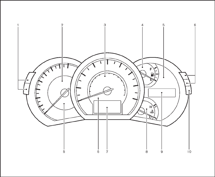
1. Instrument brightness control switch (P.2-35)
2. Tachometer (P.2-6)
3. Speedometer (P.2-5)
4. Fuel gauge (P.2-7)
5. Warning/indicator lights (P.2-10)
6. Trip computer switch (P.2-21)
7. Dot matrix liquid crystal display (P.2-17)
8. Engine coolant temperature gauge (P.2-6)
9. Vehicle information display
— Odometer/twin trip odometer (P.2-5)
— Continuously Variable Transmission (CVT)
position indicator (P.2-15)
10. RESET switch for trip odometer (P.2-5)
METERS AND GAUGES
Illustrated table of contents 0-9
Black plate (12,1)
Model "Z51-D" EDITED: 2009/ 8/ 3
SDI2172
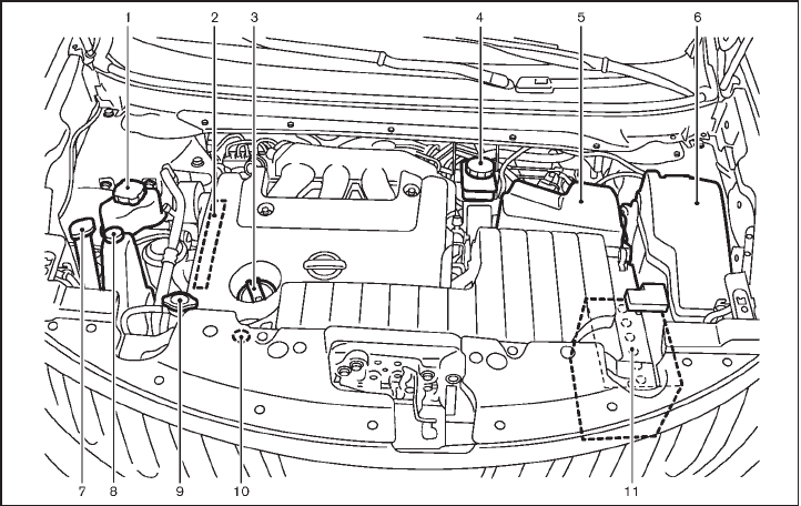
VQ35DE ENGINE
1. Power steering fluid reservoir (P.8-11)
2. Drive belt location (P.8-15)
3. Engine oil filler cap (P.8-8)
4. Brake fluid reservoir (P.8-12)
5. Air cleaner (P.8-16)
6. Fuse/fusible link holder (P.8-20)
7. Window washer fluid reservoir (P.8-12)
8. Engine coolant reservoir (P.8-7)
9. Radiator filler cap (P.8-7)
10. Engine oil dipstick (P.8-8)
11. Battery (P.8-13)
ENGINE COMPARTMENT
0-10 Illustrated table of contents
Black plate (13,1)
Model "Z51-D" EDITED: 2009/ 8/ 3
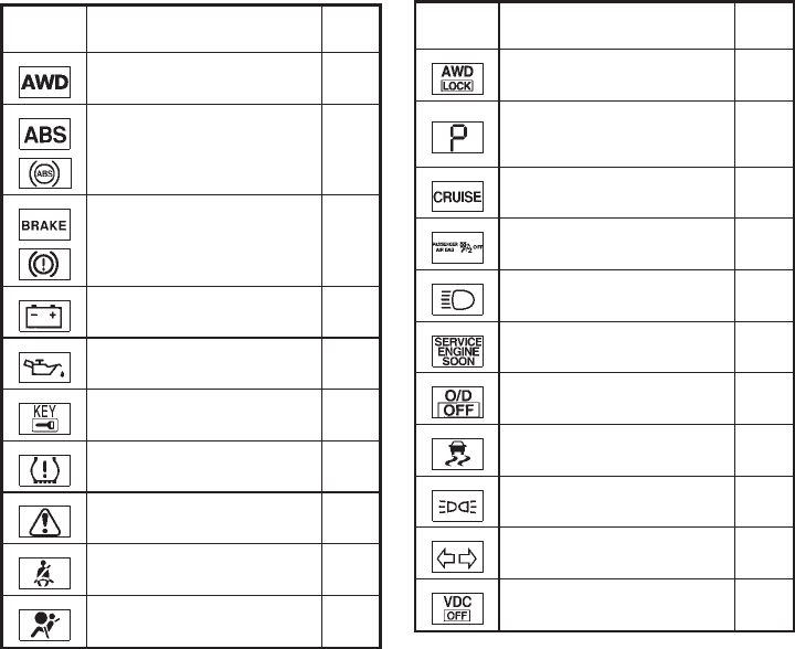
Warning
light Name Page
All-Wheel Drive (AWD) warning
light (AWD models)* 2-10
Anti-lock Braking System
(ABS) warning light 2-11
Brake warning light 2-11
Charge warning light 2-12
Engine oil pressure warning
light 2-12
Intelligent Key warning light 2-12
Low tire pressure warning light 2-12
Master warning light 2-14
Seat belt warning light 2-14
Supplemental air bag warning
light 2-14
Indicator
light Name Page
All-Wheel Drive (AWD) LOCK
indicator light (AWD models)* 2-14
Continuously Variable Trans-
mission (CVT) position indicator
light
2-15
Cruise indicator light 2-15
Front passenger air bag status
light 2-15
High beam indicator light 2-15
Malfunction Indicator Light
(MIL) 2-15
Overdrive off indicator light 2-16
Slip indicator light 2-16
Small light indicator lights 2-16
Turn signal/hazard indicator
lights 2-16
Vehicle Dynamic Control (VDC)
off indicator light 2-16
*: if so equipped
WARNING AND INDICATOR LIGHTS
Illustrated table of contents 0-11
Black plate (14,1)
Model "Z51-D" EDITED: 2009/ 8/ 3
MEMO
0-12 Illustrated table of contents

Black plate (4,1)
1 Safety — Seats, seat belts and supple-
mental restraint system
Model "Z51-D" EDITED: 2009/ 8/ 3
Seats .............................................................. 1-2
Front seats ................................................... 1-3
Rear seats.................................................... 1-6
Head restraints .............................................. 1-9
Adjustable headrest ...................................... 1-12
Armrest...................................................... 1-14
Seat belts ...................................................... 1-15
Precautions on seat belt usage ....................... 1-15
Child safety ................................................ 1-17
Pregnant women.......................................... 1-18
Injured persons............................................ 1-18
Three-point type seat belt .............................. 1-18
Seat belt extenders....................................... 1-25
Seat belt maintenance................................... 1-25
Child restraints ................................................ 1-26
Precautions on child restraints......................... 1-26
Lower Anchors and Tethers for CHildren System
(LATCH) .................................................... 1-28
Top tether strap child restraint......................... 1-29
Child restraint installation using LATCH ............. 1-31
Child restraint installation using the seat belts..... 1-35
Booster seats.................................................. 1-41
Precautions on booster seats.......................... 1-41
Booster seat installation................................. 1-43
Supplemental restraint system............................. 1-45
Precautions on supplemental restraint system ..... 1-45
NISSAN Advanced Air Bag System
(front seats) ................................................ 1-51
Front seat-mounted side-impact supplemental
air bag and roof-mounted curtain side-impact
and rollover supplemental air bag systems ......... 1-55
Seat belts with pretensioners (front seats) ......... 1-57
Supplemental air bag warning labels................. 1-58
Supplemental air bag warning light................... 1-58
Repair and replacement procedure................... 1-59
Black plate (16,1)
Model "Z51-D" EDITED: 2009/ 8/ 3
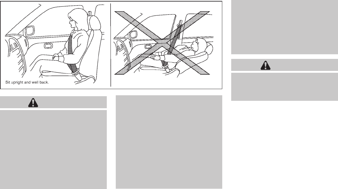
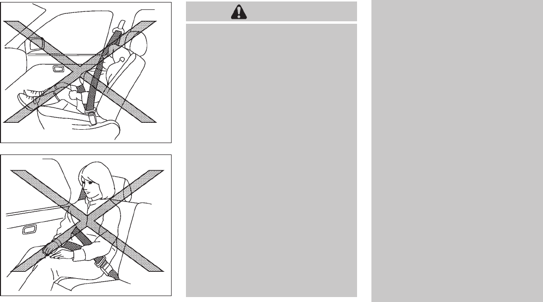
SSS0133
WARNING
.Do not ride in a moving vehicle
when the seatback is reclined. This
can be dangerous. The shoulder belt
will not be against your body. In an
accident, you could be thrown into it
and receive neck or other serious
injuries. You could also slide under
the lap belt and receive serious
internal injuries.
.For the most effective protection
when the vehicle is in motion, the
seat should be upright. Always sit
well back in the seat with both feet
on the floor and adjust the seat
properly. See “PRECAUTIONS ON
SEAT BELT USAGE” later in this
section.
.After adjustment, gently rock in the
seat to make sure it is securely
locked.
.Do not leave children unattended
inside the vehicle. They could un-
knowingly activate switches or con-
trols. Unattended children could
become involved in serious acci-
dents.
.The seatback should not be reclined
any more than needed for comfort.
Seat belts are most effective when
the passenger sits well back and
straight up in the seat. If the seat-
back is reclined, the risk of sliding
under the lap belt and being injured
is increased.
CAUTION
When adjusting the seat positions, be
sure not to contact any moving parts to
avoid possible injuries and/or da-
mages.
SEATS
1-2 Safety — Seats, seat belts and supplemental restraint system
Black plate (17,1)
Model "Z51-D" EDITED: 2009/ 8/ 3
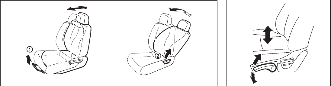
SSS0792
FRONT SEATS
Front manual seat adjustment
Forward and backward:
Pull the lever *
1up and hold it while you slide
the seat forward or backward to the desired
position. Release the lever to lock the seat in
position.
Reclining:
To recline the seatback, pull the lever *
2up and
lean back. To bring the seatback forward, pull
the lever up and lean your body forward. Release
the lever to lock the seatback in position.
The reclining feature allows adjustment of the
seatback for occupants of different sizes for
added comfort and to help obtain proper seat
belt fit. (See “PRECAUTIONS ON SEAT BELT
USAGE” later in this section.) Also, the seatback
can be reclined to allow occupants to rest when
the vehicle is stopped and the transmission in
the P (Park) position.
SSS0793
Seat lifter (if so equipped):
Pull up or push down the adjusting lever to
adjust the seat height until the desired position
is achieved.
Safety — Seats, seat belts and supplemental restraint system 1-3

Black plate (18,1)
Model "Z51-D" EDITED: 2009/ 8/ 3
SSS0684
Lumbar support (if so equipped):
The lumbar support feature provides lower back
support to the driver.
Move the lever *
1up or down to adjust the
seatback lumbar area.
Front power seat adjustment
Operating tips:
.The power seat motor has an auto-reset
overload protection circuit. If the motor
stops during operation, wait 30 seconds,
then reactivate the switch.
.Do not operate the power seat switch for a
long period of time when the engine is off.
This will discharge the battery.
See “AUTOMATIC DRIVE POSITIONER” in the
“3. Pre-driving checks and adjustments” section
for the seat position memory function.
1-4 Safety — Seats, seat belts and supplemental restraint system
Black plate (19,1)
Model "Z51-D" EDITED: 2009/ 8/ 3
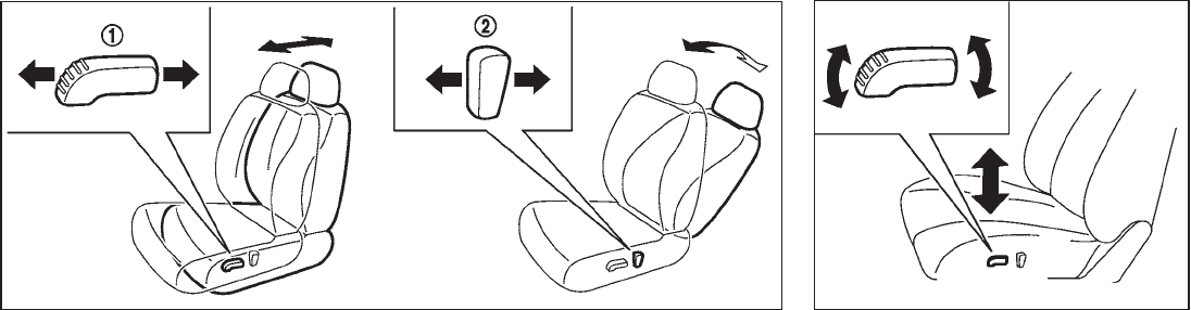
SSS1026
Forward and backward:
Moving the switch *
1forward or backward will
slide the seat forward or backward to the
desired position.
Reclining:
Move the recline switch *
2backward until the
desired angle is obtained. To bring the seatback
forward again, move the switch *
2forward.
The reclining feature allows adjustment of the
seatback for occupants of different sizes for
added comfort and to help obtain proper seat
belt fit. (See “PRECAUTIONS ON SEAT BELT
USAGE” later in this section.) Also, the seatback
can be reclined to allow occupants to rest when
the vehicle is stopped and the transmission is in
the P (Park) position.
SSS1027
Seat lifter (if so equipped):
Push the front or rear end of the switch up or
down to adjust the angle of the front portion or
height of the seat.
Safety — Seats, seat belts and supplemental restraint system 1-5

Black plate (20,1)
Model "Z51-D" EDITED: 2009/ 8/ 3
SSS1028
Lumbar support (if so equipped):
The lumbar support feature provides lower back
support to the driver.
Push the front *
1or back *
2end of the switch
to adjust the seatback lumbar area.
SSS0569
REAR SEATS
Folding
Before folding the rear seats:
.Secure the seat belts on the seat belt hooks
on the side wall. (See “Seat belt hooks” later
in this section.)
.Disconnect and stow the center seat belt
and tongue into the retractor base. (See
“Rear center seat belt” later in this section.)
.Always reconnect the center seat belt when
the seat is returned to the upright position.
.Remove drink containers from the rear cup
holder.
To fold down the seatbacks:
Pull the strap on the rear seat *
A. Pull the lever
*
Bbeside the cargo area and fold the seat-
back.
1-6 Safety — Seats, seat belts and supplemental restraint system

Black plate (21,1)
Model "Z51-D" EDITED: 2009/ 8/ 3
SSS0821
To return the seatbacks:
Manual operation:
Lift up each seatback and push it to the upright
position until it is latched.
Power operation (if so equipped):
Push and hold the corresponding switch located
on the lower side of the instrument panel *
Bor
the right or left side in the cargo area *
A.
A beep sounds once and the seatback will be
returned automatically.
A beep sounds twice when the seatback is fully
returned to the seating position.
If the control unit detects any obstacle or
malfunctions while in the power operation, a
beep sounds for 4 seconds and the seatback
will return to the folded position automatically.
Check if there are any obstacles caught that
prevent seats from returning to the folded
position. See a NISSAN dealer if the beep still
sounds.
CAUTION
When operating the rear power seat-
back return, make sure that the vehicle
is stopped and the transmission is in
the P (Park) position.
WARNING
.Never allow anyone to ride in the
cargo area or on the rear seats
when they are in the fold-down
position. In a collision, people riding
in these areas are more likely to be
seriously injured or killed.
.Do not allow people to ride in any
area of your vehicle that is not
equipped with seats and seat belts.
Be sure everyone in your vehicle is
in a seat and using a seat belt
properly.
.Do not fold down the rear seats
when occupants are in the rear seat
area or any luggage is on the rear
seats.
.When folding or returning the seat-
backs to the upright position, to
avoid injury to yourself and others:
— Make sure that the seat path is
clear before moving the seat.
— Be careful not to allow hands or
feet to get caught or pinched in
the seat.
.Properly secure all cargo to help
prevent it from sliding or shifting.
Do not place cargo higher than the
seatbacks. In a sudden stop or
collision, unsecured cargo could
cause personal injury.
.When returning the seatbacks, be
sure to attach the rear center seat
belt connector.
.Do not unfasten the rear center seat
belt connector except when folding
down the rear seat.
.When attaching the rear center seat
belt connector, be certain that the
seatbacks are completely secured in
the latched position and the rear
Safety — Seats, seat belts and supplemental restraint system 1-7

Black plate (22,1)
Model "Z51-D" EDITED: 2009/ 8/ 3
center seat belt connector is com-
pletely secured.
.If the rear center seat belt connector
and the seatbacks are not secured
in the correct position, serious per-
sonal injury may result in an acci-
dent or sudden stop.
SSS0227A
Reclining
Pull the reclining strap *
Aand position the
seatback at the desired angle. Release the
reclining strap after positioning the seat at the
desired angle.
The reclining feature allows adjustment of the
seatback for occupants of different sizes to help
obtain proper seat belt fit. (See “PRECAU-
TIONS ON SEAT BELT USAGE” later in this
section.) The seatback may also be reclined to
allow occupants to rest when the vehicle is
parked.
WARNING
.Do not ride in a moving vehicle
when the seatback is reclined. This
can be dangerous. The shoulder belt
will not be against your body. In an
accident, you could be thrown into it
and receive neck or other serious
injuries. You could also slide under
the lap belt and receive serious
internal injuries.
.For the most effective protection
when the vehicle is in motion, the
seat should be upright. Always sit
well back in the seat with both feet
on the floor and adjust the seat belt
properly. See “PRECAUTIONS ON
SEAT BELT USAGE” later in this
section.
.After adjustment, check to be sure
the seat is securely locked.
1-8 Safety — Seats, seat belts and supplemental restraint system

Black plate (23,1)
Model "Z51-D" EDITED: 2009/ 8/ 3
HEAD RESTRAINTS
WARNING
Head restraints supplement the other
vehicle safety systems. They may pro-
vide additional protection against injury
in certain rear end collisions. Adjust the
head restraints properly, as specified in
this section. Check the adjustment after
someone else uses the seat. Do not
attach anything to the head restraint
stalks or remove the head restraint. Do
not use the seat if the head restraint
has been removed. If the head restraint
was removed, reinstall and properly
adjust the head restraint before an
occupant uses the seating position.
Failure to follow these instructions
can reduce the effectiveness of the
head restraints. This may increase the
risk of serious injury or death in a
collision.
SSS1013
The illustration shows the seating positions
equipped with head restraints. The head re-
straints are adjustable.
Indicates the seating position is equipped
with a head restraint.
SSS0992
Components
1. Head restraint
2. Adjustment notches
3. Lock knob
4. Stalks
Safety — Seats, seat belts and supplemental restraint system 1-9

Black plate (24,1)
Model "Z51-D" EDITED: 2009/ 8/ 3
SSS0997
Adjustment
Adjust the head restraint so the center is level
with the center of your ears.
SSS0993
To raise the head restraint, pull it up.
SSS0994
To lower, push and hold the lock knob and push
the head restraint down.
1-10 Safety — Seats, seat belts and supplemental restraint system

Black plate (25,1)
Model "Z51-D" EDITED: 2009/ 8/ 3
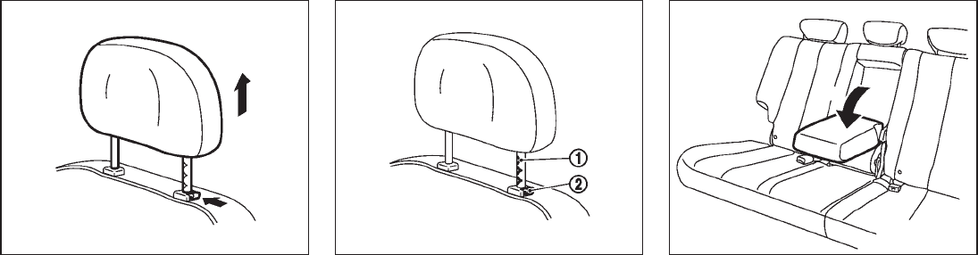
SSS0995
Removal
Use the following procedure to remove the
adjustable head restraints.
1. Pull the head restraint up to the highest
position.
2. Push and hold the lock knob.
3. Remove the head restraint from the seat.
4. Store the head restraint properly in a secure
place so it is not loose in the vehicle.
5. Install and properly adjust the head restraint
before an occupant uses the seating posi-
tion.
SSS0996
Install
1. Align the head restraint stalks with the holes
in the seat. Make sure that the head restraint
is facing the correct direction. The stalk with
the adjustment notches *
1must be in-
stalled in the hole with the lock knob *
2.
2. Push and hold the lock knob and push the
head restraint down.
3. Properly adjust the head restraint before an
occupant uses the seating position.
SSS0508
Front-seat Active Head Restraint
The Active Head Restraint moves forward
utilizing the force that the seatback receives
from the occupant in a rear-end collision. The
movement of the head restraint helps support
the occupant’s head by reducing its backward
movement and helping absorb some of the
forces that may lead to whiplash-type injuries.
Active Head Restraints are effective for colli-
sions at low to medium speeds in which it is said
that whiplash injury occurs most.
Active Head Restraints operate only in certain
rear-end collisions. After the collision, the head
restraints return to their original position.
Safety — Seats, seat belts and supplemental restraint system 1-11

Black plate (26,1)
Model "Z51-D" EDITED: 2009/ 8/ 3
Adjust the Active Head Restraints properly as
described earlier in this section.
ADJUSTABLE HEADREST
WARNING
The adjustable headrests supplement
the other vehicle safety systems. They
may provide additional protection
against injury in certain rear end colli-
sions. Adjust the headrests properly, as
specifiedinthissection.Checkthe
adjustment after someone else uses
the seat. Do not attach anything to the
adjustable headrest stalks or remove
the adjustable headrests. Do not use
the seat if the adjustable headrests
have been removed. If the headrest
was removed, reinstall and properly
adjust the headrest before an occupant
uses the seating position. Failure to
follow these instructions can reduce the
effectiveness of the adjustable head-
rests. This may increase the risk of
serious injury or death in a collision.
SSS1014
The illustration shows the seating positions
equipped with adjustable headrests. The head-
rests are adjustable.
Indicates the seating position is equipped
with an adjustable headrest.
SSS0992
Components
1. Adjustable headrest
2. Adjustment notches
3. Lock knob
4. Stalks
1-12 Safety — Seats, seat belts and supplemental restraint system

Black plate (27,1)
Model "Z51-D" EDITED: 2009/ 8/ 3
SSS0997
Adjustment
Adjust the headrest so the center is level with
the center of your ears.
SSS0993
To raise the headrest, pull it up.
SSS0994
To lower, push and hold the lock knob and push
the headrest down.
Safety — Seats, seat belts and supplemental restraint system 1-13
Black plate (28,1)
Model "Z51-D" EDITED: 2009/ 8/ 3
SSS0995
Removal
Use the following procedure to remove the
adjustable headrests.
1. Pull the headrest up to the highest position.
2. Push and hold the lock knob.
3. Remove the headrest from the seat.
4. Store the headrest properly in a secure
place so it is not loose in the vehicle.
5. Install and properly adjust the headrest
before an occupant uses the seating posi-
tion.
SSS0996
Install
1. Align the headrest stalks with the holes in
the seat. Make sure that the headrest is
facing the correct direction. The stalk with
the adjustment notches *
1must be in-
stalled in the hole with the lock knob *
2.
2. Push and hold the lock knob and push the
headrest down.
3. Properly adjust the headrest before an
occupant uses the seating position.
SSS0229A
ARMREST
Rear armrest
Pull the armrest forward until it is horizontal.
1-14 Safety — Seats, seat belts and supplemental restraint system

Black plate (29,1)
Model "Z51-D" EDITED: 2009/ 8/ 3
PRECAUTIONS ON SEAT BELT
USAGE
If you are wearing your seat belt properly
adjusted, and you are sitting upright and well
back in your seat with both feet on the floor, your
chances of being injured or killed in an accident
and/or the severity of injury may be greatly
reduced. NISSAN strongly encourages you and
all of your passengers to buckle up every time
you drive, even if your seating position includes a
supplemental air bag.
Most U.S. states and Canadian provinces
or territories specify that seat belts be
worn at all times when a vehicle is being
driven.
SSS0136
SSS0134
SEAT BELTS
Safety — Seats, seat belts and supplemental restraint system 1-15
Black plate (30,1)
Model "Z51-D" EDITED: 2009/ 8/ 3
SSS0016
SSS0014
WARNING
.Every person who drives or rides in
this vehicle should use a seat belt at
all times. Children should be prop-
erly restrained in the rear seat and,
if appropriate, in a child restraint.
.The seat belt should be properly
adjusted to a snug fit. Failure to do
so may reduce the effectiveness of
the entire restraint system and in-
crease the chance or severity of
injury in an accident. Serious injury
or death can occur if the seat belt is
not worn properly.
.Always route the shoulder belt over
your shoulder and across your
chest. Never put the belt behind
your back, under your arm or across
your neck. The belt should be away
from your face and neck, but not
falling off your shoulder.
.Position the lap belt as low and
snug as possible AROUND THE
HIPS, NOT THE WAIST. A lap belt
worn too high could increase the
risk of internal injuries in an acci-
dent.
.Be sure the seat belt tongue is
securely fastened to the proper
buckle.
.Do not wear the seat belt inside out
or twisted. Doing so may reduce its
effectiveness.
.Do not allow more than one person
to use the same seat belt.
.Never carry more people in the
vehicle than there are seat belts.
.If the seat belt warning light glows
continuously while the ignition is
turned ON with all doors closed and
all seat belts fastened, it may in-
dicate a malfunction in the system.
Have the system checked by a
NISSAN dealer.
.No changes should be made to the
seat belt system. For example, do
not modify the seat belt, add mate-
rial, or install devices that may
change the seat belt routing or
tension. Doing so may affect the
operation of the seat belt system.
Modifying or tampering with the
seat belt system may result in
serious personal injury.
.Once a seat belt pretensioner has
1-16 Safety — Seats, seat belts and supplemental restraint system

Black plate (31,1)
Model "Z51-D" EDITED: 2009/ 8/ 3
activated, it cannot be reused and
must be replaced together with the
retractor. See a NISSAN dealer.
.Removal and installation of the
pretensioner system components
should be done by a NISSAN dealer.
.All seat belt assemblies, including
retractors and attaching hardware,
should be inspected after any colli-
sion by a NISSAN dealer. NISSAN
recommends that all seat belt as-
semblies in use during a collision be
replaced unless the collision was
minor and the belts show no da-
mage and continue to operate prop-
erly. Seat belt assemblies not in use
during a collision should also be
inspected and replaced if either
damage or improper operation is
noted.
.All child restraints and attaching
hardware should be inspected after
any collision. Always follow the
restraint manufacturer’s inspection
instructions and replacement re-
commendations. The child restraints
should be replaced if they are
damaged.
CHILD SAFETY
Children need adults to help protect them.
They need to be properly restrained.
In addition to the general information in this
manual, child safety information is available from
many other sources, including doctors, teachers,
government traffic safety offices, and community
organizations. Every child is different, so be sure
to learn the best way to transport your child.
There are three basic types of child restraint
systems:
.Rear-facing child restraint
.Front-facing child restraint
.Booster seat
The proper restraint depends on the child’s size.
Generally, infants (up to about 1 year and less
than 20 lb (9 kg)) should be placed in rear-
facing child restraints. Front-facing child re-
straints are available for children who outgrow
rear-facing child restraints and are at least 1
year old. Booster seats are used to help position
a vehicle lap/shoulder belt on a child who can no
longer use a front-facing child restraint.
WARNING
Infants and children need special pro-
tection. The vehicle’s seat belts may not
fit them properly. The shoulder belt may
come too close to the face or neck. The
lap belt may not fit over their small hip
bones. In an accident, an improperly
fitting seat belt could cause serious or
fatal injury. Always use appropriate
child restraints.
All U.S. states and Canadian provinces or
territories require the use of approved child
restraints for infants and small children. (See
“CHILD RESTRAINTS” later in this section.)
Also, there are other types of child restraints
available for larger children for additional pro-
tection.
NISSAN recommends that all pre-teens
and children be restrained in the rear seat.
According to accident statistics, children
are safer when properly restrained in the
rear seat than in the front seat.
This is especially important because your
vehicle has a supplemental restraint sys-
tem (air bag system) for the front passen-
ger. (See “SUPPLEMENTAL RESTRAINT
SYSTEM” later in this section.)
Infants
Infants up to at least 1 year old should be placed
in a rear-facing child restraint. NISSAN recom-
mends that infants be placed in child restraints
Safety — Seats, seat belts and supplemental restraint system 1-17

Black plate (32,1)
Model "Z51-D" EDITED: 2009/ 8/ 3
that comply with Federal Motor Vehicle Safety
Standards or Canadian Motor Vehicle Safety
Standards. You should choose a child restraint
that fits your vehicle and always follow the
manufacturer’s instructions for installation and
use.
Small children
Children that are over 1 year old and weigh at
least 20 lb (9 kg) can be placed in a front-facing
child restraint. Refer to the manufacturer’s
instructions for minimum and maximum weight
and height recommendations. NISSAN recom-
mends that small children be placed in child
restraints that comply with Federal Motor
Vehicle Safety Standards or Canadian Motor
Vehicle Safety Standards. You should choose a
child restraint that fits your vehicle and always
follow the manufacturer’s instructions for instal-
lation and use.
Larger children
Children who are too large for child restraints
should be seated and restrained by the seat
belts which are provided. The seat belt may not
fit properly if the child is less than 4 ft 9 in (142.5
cm) tall and weighs between 40 lb (18 kg) and
80 lb (36 kg). A booster seat should be used to
obtain proper seat belt fit.
NISSAN recommends that a child be placed in a
commercially availableboosterseatifthe
shoulder belt in the child’s seating position fits
close to the face or neck or if the lap portion of
the seat belt goes across the abdomen. The
booster seat should raise the child so that the
shoulder belt is properly positioned across the
top, middle portion of the shoulder and the lap
belt is low on the hips. A booster seat can only
be used in seating positions that have a three-
point type seat belt. The booster seat should fit
the vehicle seat and have a label certifying that it
complies with Federal Motor Vehicle Safety
Standards or Canadian Motor Vehicle Safety
Standards. Once the child has grown so the
shoulder belt is no longer on or near the face
and neck, use the shoulder belt without the
booster seat.
WARNING
Never let a child stand or kneel on any
seat and do not allow a child in the
cargo areas while the vehicle is moving.
The child could be seriously injured or
killed in an accident or sudden stop.
PREGNANT WOMEN
NISSAN recommends that pregnant women use
seat belts. The seat belt should be worn snug,
and always position the lap belt as low as
possible around the hips, not the waist. Place
the shoulder belt over your shoulder and across
your chest. Never run the lap/shoulder belt over
your abdominal area. Contact your doctor for
specific recommendations.
INJURED PERSONS
NISSAN recommends that injured persons use
seat belts, depending on the injury. Check with
your doctor for specific recommendations.
THREE-POINT TYPE SEAT BELT
WARNING
.Every person who drives or rides in
this vehicle should use a seat belt at
all times.
.Do not ride in a moving vehicle
when the seatback is reclined. This
can be dangerous. The shoulder belt
will not be against your body. In an
accident, you could be thrown into it
and receive neck or other serious
injuries. You could also slide under
the lap belt and receive serious
internal injuries.
.For the most effective protection
when the vehicle is in motion, the
seat should be upright. Always sit
well back in the seat with both feet
on the floor and adjust the seat belt
1-18 Safety — Seats, seat belts and supplemental restraint system

Black plate (33,1)
Model "Z51-D" EDITED: 2009/ 8/ 3
properly.
SSS0292
Fastening the seat belts
1. Adjust the seat. (See “SEATS” earlier in this
section.)
2. Slowly pull the seat belt out of the retractor
and insert the tongue into the buckle until
you hear and feel the latch engage.
.The retractor is designed to lock
during a sudden stop or on impact.
A slow pulling motion permits the
belt to move and allows you some
freedom of movement in the seat.
.If the seat belt cannot be pulled
from its fully retracted position,
firmly pull the belt and release it.
Then smoothly pull the belt out of
the retractor.
Safety — Seats, seat belts and supplemental restraint system 1-19

Black plate (34,1)
Model "Z51-D" EDITED: 2009/ 8/ 3
SSS0290
3. Position the lap belt portion low and snug
on the hips as shown.
4. Pull the shoulder belt portion toward the
retractor to take up extra slack. Be sure the
shoulder belt is routed over your shoulder
and across your chest.
The front passenger seat and the rear seating
positions three-point seat belts have two modes
of operation:
.Emergency Locking Retractor (ELR)
.Automatic Locking Retractor (ALR)
The Emergency Locking Retractor (ELR) mode
allows the seat belt to extend and retract to
allow the driver and passengers some freedom
of movement in the seat. The ELR locks the seat
belt when the vehicle slows down rapidly or
during certain impacts.
The Automatic Locking Retractor (ALR) mode
(child restraint mode) locks the seat belt for
child restraint installation.
When ALR mode is activated the seat belt
cannot be extended again until the seat belt
tongue is detached from the buckle and fully
retracted. The seat belt returns to the ELR mode
after the seat belt fully retracts. For additional
information, see “CHILD RESTRAINTS” later in
this section.
The ALR mode should be used only for
child restraint installation. During normal
seat belt use by an occupant, the ALR
mode should not be activated. If it is
activated, it may cause uncomfortable seat
belt tension.
WARNING
When fastening the seat belts, be
certain that seatbacks are completely
secured in the latched position. If they
are not completely secured, passengers
may be injured in an accident or sudden
stop.
SSS0326
Unfastening the seat belts
To unfasten the seat belt, push the button on the
buckle. The seat belt automatically retracts.
Checking seat belt operation
Seat belt retractors are designed to lock seat
belt movement by two separate methods:
.When the belt is pulled quickly from the
retractor.
.When the vehicle slows down rapidly.
To increase your confidence in the seat belts,
check the operation as follows:
.Grasp the shoulder belt and pull forward
quickly. The retractor should lock and
1-20 Safety — Seats, seat belts and supplemental restraint system

Black plate (35,1)
Model "Z51-D" EDITED: 2009/ 8/ 3
restrict further belt movement.
If the retractor does not lock during this check or
if you have any question about seat belt
operation, see a NISSAN dealer.
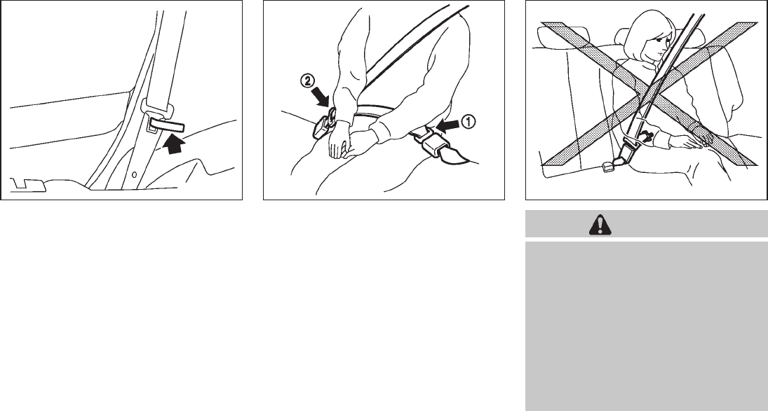
SSS0351A
Shoulder belt height adjustment
The shoulder belt anchor height should be
adjusted to the position best for you. (See
“PRECAUTIONS ON SEAT BELT USAGE”
earlier in this section.)
To adjust, pull the adjustment button *
1, and
then move the shoulder belt anchor to the
desired position *
2, so that the belt passes
over the center of the shoulder. The belt should
be away from your face and neck, but not falling
off of your shoulder. Release the adjustment
button to lock the shoulder belt anchor into
position.
WARNING
.After adjustment, release the ad-
justment button and try to move the
shoulder belt anchor up and down
to make sure it is securely fixed in
position.
.The shoulder belt anchor height
should be adjusted to the position
best for you. Failure to do so may
reduce the effectiveness of the
entire restraint system and increase
the chance or severity of injury in an
accident.
Safety — Seats, seat belts and supplemental restraint system 1-21
Black plate (36,1)
Model "Z51-D" EDITED: 2009/ 8/ 3
SSS0845
Seat belt hooks
When the rear seat belts are not in use and
when folding down the rear seats, hook the rear
outer seat belts on the seat belt hooks.
SSS0846
Rear center seat belt
The rear center seat belt has a connector tongue
*
1and a seat belt tongue *
2. Both the
connector tongue and the seat belt tongue must
be securely latched for proper seat belt opera-
tion.
SSS0241
WARNING
.Always fasten the connector tongue
and the seat belt in the order shown.
.Always make sure both the connec-
tor tongue and the seat belt tongue
are secured when using the seat
belt or installing a child restraint. Do
notusetheseatbeltorchild
restraint with only the seat belt
tongue attached. This could result
in serious personal injury in case of
an accident or a sudden stop.
1-22 Safety — Seats, seat belts and supplemental restraint system

Black plate (37,1)
Model "Z51-D" EDITED: 2009/ 8/ 3
SSS0703
The center seat belt buckle and the tongue are
identified by the CENTER mark. The center seat
belt tongue can be fastened only into the center
seat belt buckle.
SSS0225
Stowing rear center seat belt:
When folding down the rear seat, the rear center
seat belt can be retracted into a stowed position
as follows:
1. Hold the connector tongue *
1so that the
seat belt does not retract suddenly when the
tongue is released from the connector
buckle. Release the connector tongue by
inserting a suitable tool such as key *
Ainto
the connector buckle.
2. Insert the seat belt tongue into the retractor
base first *
2.
3. Then secure the connector tongue into the
retractor base *
3.
WARNING
.Do not unfasten the rear center seat
belt connector except when folding
down the rear seat.
.When attaching the rear center seat
belt connector, be certain that the
seatbacks are completely secured in
the latched position and the rear
center seat belt connector is com-
pletely secured.
.If the rear center seat belt connector
and the seatbacks are not secured
Safety — Seats, seat belts and supplemental restraint system 1-23

Black plate (38,1)
Model "Z51-D" EDITED: 2009/ 8/ 3
in the correct position, serious per-
sonal injury may result in an acci-
dent or sudden stop.
SSS0232
Attaching rear center seat belt:
Always be sure the rear center seat belt
connector tongue and connector buckle are
attached. Disconnect only when folding down
the rear seat.
To connect the buckle:
1. Pull out the connector tongue from the
retractor base *
1.
2. Pull out the seat belt tongue from the
retractor base *
2.
3. Pull the seat belt and secure the connector
buckle until it clicks *
3.
The center seat belt connector tongue and
buckle are indicated by the !and ~mark.
The center seat belt connector tongue can be
attached only into the rear center seat belt
connector buckle.
To fasten the seat belt, see “Fastening the seat
belts” earlier in this section.
WARNING
.Do not unfasten the rear center seat
belt connector except when folding
down the rear seat.
.When attaching the rear center seat
1-24 Safety — Seats, seat belts and supplemental restraint system

Black plate (39,1)
Model "Z51-D" EDITED: 2009/ 8/ 3
belt connector, be certain that the
seatbacks are completely secured in
the latched position and the rear
center seat belt connector is com-
pletely secured.
.If the rear center seat belt connector
and the seatbacks are not secured
in the correct position, serious per-
sonal injury may result in an acci-
dent or sudden stop.
SSS0235
Storing rear seat belt buckles
Before folding down the seat, put the buckles in
the storage of the seat cushion to avoid
dropping it under the seat cushion.
SEAT BELT EXTENDERS
If, because of body size or driving position, it is
not possible to properly fit the lap-shoulder belt
and fasten it, an extender is available that is
compatible with the installed seat belts. The
extender adds approximately 8 in (200 mm) of
length and may be used for either the driver or
front passenger seating position. See a NISSAN
dealer for assistance if an extender is required.
WARNING
.Only NISSAN seat belt extenders,
made by the same company which
made the original equipment seat
belts, should be used with NISSAN
seat belts.
.Adults and children who can use the
standard seat belt should not use an
extender. Such unnecessary use
could result in serious personal
injury in the event of an accident.
.Never use seat belt extenders to
install child restraints. If the child
restraint is not secured properly, the
child could be seriously injured in a
collision or a sudden stop.
SEAT BELT MAINTENANCE
.To clean the seat belt webbing, apply a
mild soap solution or any solution recom-
mended for cleaning upholstery or carpets.
Then wipe with a cloth and allow the seat
belts to dry in the shade. Do not allow the
seat belts to retract until they are completely
dry.
.If dirt builds up in the shoulder belt
guide of the seat belt anchors, the seat
Safety — Seats, seat belts and supplemental restraint system 1-25

Black plate (40,1)
Model "Z51-D" EDITED: 2009/ 8/ 3
belts may retract slowly. Wipe the shoulder
belt guide with a clean, dry cloth.
.Periodically check to see that the seat
belt and the metal components, such as
buckles, tongues, retractors, flexible wires
and anchors, work properly. If loose parts,
deterioration, cuts or other damage on the
webbing is found, the entire seat belt
assembly should be replaced.
SSS0099
SSS0100
PRECAUTIONS ON CHILD
RESTRAINTS
WARNING
.Infants and small children should
always be placed in an appropriate
child restraint while riding in the
vehicle. Failure to use a child re-
straint can result in serious injury or
death.
.Infants and small children should
never be carried on your lap. It is not
possible for even the strongest
adult to resist the forces of a severe
accident. The child could be crushed
between the adult and parts of the
vehicle. Also, do not put the same
seat belt around both your child and
yourself.
.Even with the NISSAN Advanced Air
Bag System, never install a rear-
facing child restraint in the front
seat. An inflating front air bag could
seriously injure or kill your child. A
rear-facing child restraint must only
be used in the rear seat.
.NISSAN recommends that the child
restraint be installed in the rear
CHILD RESTRAINTS
1-26 Safety — Seats, seat belts and supplemental restraint system

Black plate (41,1)
Model "Z51-D" EDITED: 2009/ 8/ 3
seat. According to accident statis-
tics, children are safer when prop-
erly restrained in the rear seat than
in the front seat. If you must install a
front-facing child restraint in the
front seat, see “CHILD RESTRAINT
INSTALLATION USING THE SEAT
BELTS” later in this section.
.Improper use or improper installa-
tion of a child restraint can increase
the risk or severity of injury for both
the child and other occupants of the
vehicle and can lead to serious
injury or death in an accident.
.Follow all of the child restraint
manufacturer’s instructions for in-
stallation and use. When purchasing
a child restraint, be sure to select
one which will fit your child and
vehicle. It may not be possible to
properly install some types of child
restraints in your vehicle.
.If the child restraint is not anchored
properly, the risk of a child being
injured in a collision or a sudden
stop greatly increases.
.Child restraint anchor points are
designed to withstand only those
loads imposed by correctly fitted
child restraints. Under no circum-
stances are they to be used for adult
seat belts or harnesses.
.Adjustable seatbacks should be
positioned to fit the child restraint,
but as upright as possible.
.After attaching the child restraint,
test it before you place the child in
it. Push it from side to side while
holding the seat near the LATCH
attachment or by the seat belt path.
The child restraint should not move
more than 1 inch (25 mm) from side
to side. Try to tug it forward and
check to see if the belt holds the
restraint in place. If the restraint is
not secure, tighten the belt as
necessary, or put the restraint in
another seat and test it again. You
may need to try a different child
restraint. Not all child restraints fit
in all types of vehicles.
.When your child restraint is not in
use, keep it secured with the LATCH
System or a seat belt to prevent it
from being thrown around in case of
a sudden stop or accident.
CAUTION
Remember that a child restraint left in a
closed vehicle can become very hot.
Check the seating surface and buckles
before placing your child in the child
restraint.
This vehicle is equipped with a universal child
restraint lower anchor system, referred to as the
Lower Anchors and Tethers for CHildren System
or LATCH. Some child restraints include two
rigid or webbing-mounted attachments that can
be connected to these lower anchors. For
details, see “Lower Anchors and Tethers for
CHildren System (LATCH)” later in this section.
If you do not have a LATCH compatible child
restraint, the vehicle seat belts can be used.
(See “CHILD RESTRAINT INSTALLATION
USING THE SEAT BELTS” later in this section.)
In general, child restraints are also designed to
be installed with the lap portion of a lap/shoulder
seat belt.
Several manufacturers offer child restraints for
infants and small children of various sizes. When
selecting any child restraint, keep the following
points in mind:
.Choose only a restraint with a label certifying
that it complies with Federal Motor Vehicle
Safety Standard 213 or Canadian Motor
Safety — Seats, seat belts and supplemental restraint system 1-27

Black plate (42,1)
Model "Z51-D" EDITED: 2009/ 8/ 3
Vehicle Safety Standard 213.
.Check the child restraint in your vehicle to
be sure it is compatible with the vehicle’s
seat and seat belt system.
.If the child restraint is compatible with your
vehicle, place your child in the child restraint
and check the various adjustments to be
sure the child restraint is compatible with
your child. Choose a child restraint that is
designed for your child’s height and weight.
Always follow all recommended procedures.
All U.S. states and Canadian provinces or
territories require that infants and small
children be restrained in an approved child
restraint at all times while the vehicle is
being operated. Canadian law requires the
top tether strap on front-facing child
restraints to be secured to the designated
anchor point on the vehicle.
Lower Anchors and Tethers for CHildren
System (LATCH)
Your vehicle is equipped with special anchor
points that are used with Lower Anchors and
Tethers for CHildren System (LATCH) compa-
tible child restraints. This system may also be
referred to as the ISOFIX or ISOFIX compatible
system. With this system, you do not have to use
a vehicle seat belt to secure the child restraint.
The LATCH anchor points are provided to install
child restraints in the rear outboard seating
positions only. Do not attempt to install a child
restraint in the center position using the LATCH
anchors.
SSS0419B
LATCH system anchor location
SSS0637
LATCH system lower anchor
1-28 Safety — Seats, seat belts and supplemental restraint system

Black plate (43,1)
Model "Z51-D" EDITED: 2009/ 8/ 3
LATCH lower anchor point locations
The LATCH anchors are located at the rear of
the seat cushion near the seatback. A label is
attached to the seatback to help you locate the
LATCH anchors.
WARNING
.Attach LATCH system compatible
child restraints only at the locations
shown in the illustration. If a child
restraint is not secured properly,
your child could be seriously injured
or killed in an accident.
.Do not secure a child restraint in the
center rear seating position using
the LATCH anchors. The child re-
straint will not be secured properly.
.Child restraint anchor points are
designed to withstand only those
loads imposed by correctly fitted
child restraints. Under no circum-
stances are they to be used for adult
seat belts or harnesses.
SSS0643
LATCH webbing-mounted attachment
Installing child restraint LATCH anchor
attachments
LATCH compatible child restraints include two
rigid or webbing-mounted attachments that can
be connected to two anchors located at certain
seating positions in your vehicle. With this
system, you do not have to use a vehicle seat
belt to secure the child restraint. Check your
child restraint for a label stating that it is
compatible with LATCH system. This information
may also be in the instructions provided by the
child restraint manufacturer.
SSS0644
LATCH rigid-mounted attachment
LATCH child restraints generally require the use
of a top tether strap. (See “TOP TETHER
STRAP CHILD RESTRAINT” later in this section
for installation instructions.)
When installing a child restraint, carefully read
and follow the instructions in this manual and
those supplied with the child restraint. (See
“CHILD RESTRAINT INSTALLATION USING
LATCH” later in this section.)
TOP TETHER STRAP CHILD RE-
STRAINT
If the manufacturer of your child restraint
requires the use of a top tether strap, it must
be secured to an anchor point.
Safety — Seats, seat belts and supplemental restraint system 1-29

Black plate (44,1)
Model "Z51-D" EDITED: 2009/ 8/ 3
WARNING
.Child restraint anchor points are
designed to withstand only those
loads imposed by correctly fitted
child restraints. Under no circum-
stances are they to be used for adult
seat belts or harnesses.
.Your child could be seriously injured
or killed in a collision if the child
restraint top tether strap is da-
maged.
— If the cargo cover contacts the
top tether strap when it is at-
tached to the top tether anchor,
remove the cargo cover from the
vehicle or secure it on the cargo
floor below its attachment loca-
tion. If the cargo cover is not
removed, it may damage the top
tether strap during a collision.
— Do not allow cargo to contact
the top tether strap when it is
attached to the top tether an-
chor. Properly secure the cargo
so it does not contact the top
tether strap. Cargo that is not
properly secured or that con-
tacts the top tether strap may
damage the top tether strap
during a collision.
SSS0822
Top tether anchor point locations
Anchor points are located on the seatbacks.
Installing top tether strap
First secure the child restraint with the LATCH
system (rear outboard seating positions only) or
the seat belt as applicable.
1. Remove the headrest from the seatback.
Store it in a secure place.
2. Position the top tether strap over the top of
the seatback.
3. Secure the tether strap to the tether anchor
bracket that provides the straightest instal-
lation.
1-30 Safety — Seats, seat belts and supplemental restraint system

Black plate (45,1)
Model "Z51-D" EDITED: 2009/ 8/ 3
4. Tighten the tether strap according to the
manufacturer’s instructions to remove any
slack.
If you have any questions when installing a
top tether strap child restraint on the rear
seat, consult your NISSAN dealer for de-
tails.
CHILD RESTRAINT INSTALLATION
USING LATCH
WARNING
.Attach LATCH system compatible
child restraints only at the locations
shown. For the LATCH lower anchor
locations, see “Lower Anchors and
Tethers for CHildren System
(LATCH)” earlier in this section. If a
child restraint is not secured prop-
erly, your child could be seriously
injured or killed in an accident.
.The LATCH anchors are designed to
withstand only those loads imposed
by correctly fitted child restraints.
Under no circumstance are they to
be used for adult seat belts or
harnesses.
.Inspect the lower anchors by insert-
ing your fingers into the lower
anchor area and feeling to make
sure there are no obstructions over
the LATCH anchors, such as seat
belt webbing or seat cushion mate-
rial. The child restraint will not be
secured properly if the LATCH an-
chors are obstructed.
Front-facing
Follow these steps to install a front-facing child
restraint using LATCH system:
1. Adjust the rear seatback to the upright
position.
2. Position the child restraint on the seat.
Always follow the child restraint manufac-
turer’s instructions.
SSS0645
Front-facing (webbing-mounted) — step 3
3. Secure the child restraint anchor attach-
ments to the LATCH lower anchors. Check
to make sure the LATCH attachment is
properly attached to the lower anchors.
Safety — Seats, seat belts and supplemental restraint system 1-31
Black plate (46,1)
Model "Z51-D" EDITED: 2009/ 8/ 3
SSS0646
Front-facing (rigid-mounted) — step 3
4. The back of the child restraint should be
secured against the vehicle seatback. If
necessary, adjust or remove the headrest
to obtain the correct child restraint fit. (See
“HEAD RESTRAINTS” earlier in this sec-
tion.)
If the headrest is removed, store it in a
secure place. Be sure to reinstall the
headrest when the child restraint is re-
moved.
If the seating position does not have an
adjustable headrest and it is interfering with
the proper child restraint fit, try another
seating position or a different child restraint.
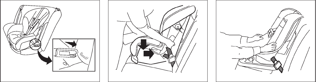
SSS0647
Front-facing — step 5
5. For child restraints that are equipped with
webbing-mounted attachments, remove any
additional slack from the anchor attach-
ments. Press downward and rearward firmly
in the center of the child restraint with your
knee to compress the vehicle seat cushion
and seatback while tightening the webbing
of the anchor attachments.
6. If the child restraint is equipped with a top
tether strap, route the top tether strap and
secure the tether strap to the tether anchor
point. (See “TOP TETHER STRAP CHILD
RESTRAINT” earlier in this section.)
SSS0638
Front-facing — step 7
7. After attaching the child restraint, test it
before you place the child in it. Push it from
side to side while holding the seat near the
LATCH attachment path. The child restraint
should not move more than 1 inch (25 mm)
from side to side. Try to tug it forward and
check to see if the LATCH attachment holds
the restraint in place. If the restraint is not
secure, tighten the LATCH attachment as
necessary, or put the restraint in another
seat and test it again. You may need to try a
different child restraint. Not all child re-
straints fit in all types of vehicles.
1-32 Safety — Seats, seat belts and supplemental restraint system

Black plate (47,1)
Model "Z51-D" EDITED: 2009/ 8/ 3
8. Check to make sure the child restraint is
properly secured prior to each use. If the
child restraint is loose, repeat steps 4
through 7.
Rear-facing
Follow these steps to install a rear-facing child
restraint using the LATCH system:
1. Position the child restraint on the seat.
Always follow the child restraint manufac-
turer’s instructions.
SSS0648
Rear-facing (webbing-mounted) — step 2
2. Secure the child restraint anchor attach-
ments to the LATCH lower anchors. Check
to make sure the LATCH attachment is
properly attached to the lower anchors.
SSS0649
Rear-facing (rigid-mounted) — step 2
Safety — Seats, seat belts and supplemental restraint system 1-33

Black plate (48,1)
Model "Z51-D" EDITED: 2009/ 8/ 3
SSS0639
Rear-facing — step 3
3. For child restraints that are equipped with
webbing-mounted attachments, remove any
additional slack from the anchor attach-
ments. Press downward and rearward firmly
in the center of the child restraint with your
hand to compress the vehicle seat cushion
and seatback while tightening the webbing
of the anchor attachments.
SSS0650
Rear-facing — step 4
4. After attaching the child restraint, test it
before you place the child in it. Push it from
side to side while holding the seat near the
LATCH attachment path. The child restraint
should not move more than 1 inch (25 mm)
from side to side. Try to tug it forward and
check to see if the LATCH attachment holds
the restraint in place. If the restraint is not
secure, tighten the LATCH attachment as
necessary, or put the restraint in another
seat and test it again. You may need to try a
different child restraint. Not all child re-
straints fit in all types of vehicles.
5. Check to make sure the child restraint is
properly secured prior to each use. If the
child restraint is loose, repeat steps 3
through 4.
1-34 Safety — Seats, seat belts and supplemental restraint system

Black plate (49,1)
Model "Z51-D" EDITED: 2009/ 8/ 3
SSS0100
CHILD RESTRAINT INSTALLATION
USING THE SEAT BELTS
WARNING
.Even with the NISSAN Advanced Air
Bag System, never install a rear-
facing child restraint in the front
passenger seat. Front air bags in-
flate with great force. A rear-facing
child restraint could be struck by the
front air bag in a crash and could
seriously injure or kill your child.
.NISSAN recommends that child re-
straints be installed in the rear seat.
However, if you must install a front-
facing child restraint in the front
passenger seat, move the passen-
ger seat to the rearmost position.
Also, be sure the front passenger air
bag status light is illuminated to
indicate the passenger air bag is
OFF. See “Front passenger air bag
and status light” later in this section
for details.
.The three-point seat belt in your
vehicle is equipped with an Auto-
matic Locking Retractor (ALR) which
must be used when installing a child
restraint.
.Failure to use the ALR mode will
result in the child restraint not being
properly secured. The restraint
could tip over or otherwise be un-
secured and cause injury to the child
in a sudden stop or collision.
.When using the rear center seat belt
to install a child restraint, make sure
the connector tongue and the seat
belt tongue are secured. Do not use
the seat belt with only the seat belt
tongue attached. This could result in
serious personal injury in case of an
accident or sudden stop.
.A child restraint with a top tether
strap should not be used in the front
passenger seat.
The instructions in this section apply to child
restraint installation using the vehicle seat belts
in the rear seat or the front passenger seat.
Safety — Seats, seat belts and supplemental restraint system 1-35

Black plate (50,1)
Model "Z51-D" EDITED: 2009/ 8/ 3
SSS0640
Front-facing (front passenger seat) — step 1
Front-facing
Follow these steps to install a front-facing child
restraint using the vehicle seat belt in the rear
seat or in the front passenger seat:
1. Adjust the rear seatback to the upright
position.
If you must install a child restraint in
the front seat, it should be placed in a
front-facing direction only. Move the
seat to the rearmost position. Child
restraints for infants must be used in
the rear-facing direction and therefore
must not be used in the front seat.
2. Position the child restraint on the seat.
Always follow the child restraint manufac-
turer’s instructions.
The back of the child restraint should be
secured against the seatback. If necessary,
adjust or remove the head restraint/headrest
(front passenger seat only) to obtain the
correct child restraint fit. (See “HEAD
RESTRAINTS” earlier in this section.)
If the head restraint/headrest is removed,
store it in a secure place. Be sure to reinstall
the head restraint/headrest when the child
restraint is removed.
If the seating position does not have an
adjustable head restraint/headrest and it is
interfering with the proper child restraint fit,
try another seating position or a different
child restraint.
SSS0360B
Front-facing — step 3
3. Route the seat belt tongue through the child
restraint and insert it into the buckle until you
hear and feel the latch engage. Be sure to
follow the child restraint manufacturer’s
instructions for belt routing.
1-36 Safety — Seats, seat belts and supplemental restraint system

Black plate (51,1)
Model "Z51-D" EDITED: 2009/ 8/ 3
SSS0651
Front-facing — step 4
4. Pull the shoulder belt until the belt is fully
extended. At this time, the seat belt retractor
is in the Automatic Locking Retractor (ALR)
mode (child restraint mode). It reverts to
Emergency Locking Retractor (ELR) mode
when the seat belt is fully retracted.
SSS0652
Front-facing — step 5
5. Allow the seat belt to retract. Pull up on the
shoulder belt to remove any slack in the belt.
SSS0653
Front-facing — step 6
6. Remove any additional slack from the seat
belt; press downward and rearward firmly in
the center of the child restraint with your
knee to compress the vehicle seat cushion
and seatback while pulling up on the seat
belt.
7. If the child restraint is equipped with a top
tether strap, route the top tether strap and
secure the tether strap to the tether anchor
point (rear seat installation only). (See “TOP
TETHER STRAP CHILD RESTRAINT” ear-
lier in this section.) Do not install child
restraints that require the use of a top tether
strap to seating positions that do not have a
top tether anchor.
Safety — Seats, seat belts and supplemental restraint system 1-37
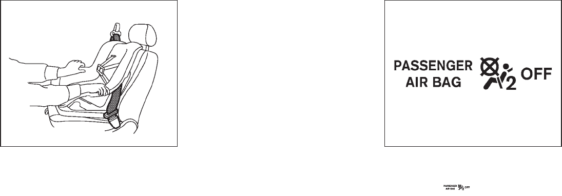
Black plate (52,1)
Model "Z51-D" EDITED: 2009/ 8/ 3
SSS0641
Front-facing — step 8
8. After attaching the child restraint, test it
before you place the child in it. Push it from
side to side while holding the seat near the
seat belt path. The child restraint should not
move more than 1 inch (25 mm) from side to
side. Try to tug it forward and check to see if
the belt holds the restraint in place. If the
restraint is not secure, tighten the belt as
necessary, or put the restraint in another
seat and test it again. You may need to try a
different child restraint. Not all child re-
straints fit in all types of vehicles.
9. Check that the retractor is in the ALR mode
by trying to pull more seat belt out of the
retractor. If you cannot pull any more belt
webbing out of the retractor, the retractor is
in the ALR mode.
10. Check to make sure the child restraint is
properly secured prior to each use. If the
seat belt is not locked, repeat steps 3
through 9.
SSS0823
Front-facing — step 11
11. If the child restraint is installed in the front
passenger seat, turn the ignition switch to
the ON position. The front passenger air bag
status light should illuminate. If this
light is not illuminated, see “Front passenger
air bag and status light” later in this section.
Move the child restraint to another
seating position. Have the system
checked by a NISSAN dealer.
After the child restraint is removed and the seat
belt is fully retracted, the ALR mode (child
restraint mode) is canceled.
1-38 Safety — Seats, seat belts and supplemental restraint system

Black plate (53,1)
Model "Z51-D" EDITED: 2009/ 8/ 3
SSS0100
Rear-facing
Follow these steps to install a rear-facing child
restraint using the vehicle seat belt in the rear
seat:
1. Child restraints for infants must be
used in the rear-facing direction and
therefore must not be used in the front
seat. Position the child restraint on the seat.
Always follow the restraint manufacturer’s
instructions.
SSS0654
Rear-facing — step 2
2. Route the seat belt tongue through the child
restraint and insert it into the buckle until you
hear and feel the latch engage. Be sure to
follow the child restraint manufacturer’s
instructions for belt routing.
SSS0655
Rear-facing — step 3
3. Pull the shoulder belt until the belt is fully
extended. At this time, the seat belt retractor
is in the Automatic Locking Retractor (ALR)
mode (child restraint mode). It reverts to
Emergency Locking Retractor (ELR) mode
when the seat belt is fully retracted.
Safety — Seats, seat belts and supplemental restraint system 1-39
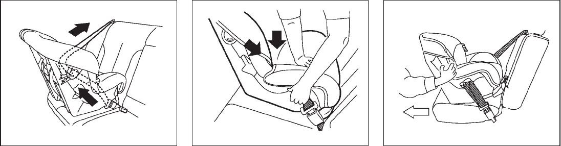
Black plate (54,1)
Model "Z51-D" EDITED: 2009/ 8/ 3
SSS0656
Rear-facing — step 4
4. Allow the seat belt to retract. Pull up on the
shoulder belt to remove any slack in the belt.
SSS0657
Rear-facing — step 5
5. Remove any additional slack from the child
restraint; press downward and rearward
firmly in the center of the child restraint with
your hand to compress the vehicle seat
cushion and seatback while pulling up on
the seat belt.
SSS0658
Rear-facing — step 6
6. After attaching the child restraint, test it
before you place the child in it. Push it from
side to side while holding the seat near the
seat belt path. The child restraint should not
move more than 1 inch (25 mm) from side to
side. Try to tug it forward and check to see if
the belt holds the restraint in place. If the
restraint is not secure, tighten the belt as
necessary, or put the restraint in another
seat and test it again. You may need to try a
different child restraint. Not all child re-
straints fit in all types of vehicles.
1-40 Safety — Seats, seat belts and supplemental restraint system

Black plate (55,1)
Model "Z51-D" EDITED: 2009/ 8/ 3
7. Check that the retractor is in the ALR mode
by trying to pull more seat belt out of the
retractor. If you cannot pull any more seat
belt webbing out of the retractor, the
retractor is in the ALR mode.
8. Check to make sure that the child restraint is
properly secured prior to each use. If the
seat belt is not locked, repeat steps 3
through 7.
After the child restraint is removed and the seat
belt fully retracted, the ALR mode (child restraint
mode) is canceled.
SSS0099
PRECAUTIONS ON BOOSTER SEATS
WARNING
.Infants and small children should
always be placed in an appropriate
child restraint while riding in the
vehicle. Failure to use a child re-
straint or booster seat can result in
serious injury or death.
.Infants and small children should
never be carried on your lap. It is not
possible for even the strongest
adult to resist the forces of a severe
accident. The child could be crushed
between the adult and parts of the
vehicle. Also, do not put the same
seat belt around both your child and
yourself.
.NISSAN recommends that the boos-
ter seat be installed in the rear seat.
According to accident statistics,
children are safer when properly
restrained in the rear seat than in
the front seat. If you must install a
booster seat in the front seat, see
“BOOSTER SEAT INSTALLATION”
later in this section.
.A booster seat must only be in-
stalled in a seating position that has
a lap/shoulder belt. Failure to use a
three-point type seat belt with a
booster seat can result in a serious
injury in sudden stop or collision.
.Improper use or improper installa-
tion of a booster seat can increase
the risk or severity of injury for both
the child and other occupants of the
vehicle and can lead to serious
injury or death in an accident.
.Do not use towels, books, pillows or
other items in place of a booster
seat. Items such as these may move
BOOSTER SEATS
Safety — Seats, seat belts and supplemental restraint system 1-41

Black plate (56,1)
Model "Z51-D" EDITED: 2009/ 8/ 3
during normal driving or a collision
and result in serious injury or death.
Booster seats are designed to be
used with a lap/shoulder belt. Boos-
ter seats are designed to properly
route the lap and shoulder portions
of the seat belt over the strongest
portions of a child’s body to provide
the maximum protection during a
collision.
.Follow all of the booster seat man-
ufacturer’s instructions for installa-
tion and use. When purchasing a
booster seat, be sure to select one
which will fit your child and vehicle.
It may not be possible to properly
install some types of booster seats
in your vehicle.
.If the booster seat and seat belt is
not used properly, the risk of a child
being injured in a collision or a
sudden stop greatly increases.
.Adjustable seatbacks should be
positioned to fit the booster seat,
but as upright as possible.
.After placing the child in the booster
seat and fastening the seat belt,
make sure the shoulder portion of
the belt is away from the child’s face
and neck and the lap portion of the
belt does not cross the abdomen.
.Do not put the shoulder belt behind
the child or under the child’s arm. If
you must install a booster seat in
the front seat, see “BOOSTER SEAT
INSTALLATION” later in this section.
.When your booster seat is not in
use, keep it secured with a seat belt
to prevent it from being thrown
around in case of a sudden stop or
accident.
CAUTION
Remember that a booster seat left in a
closed vehicle can become very hot.
Check the seating surface and buckles
before placing your child in the booster
seat.
LRS0455
Booster seats of various sizes are offered by
several manufacturers. When selecting any
booster seat, keep the following points in mind:
.Choose only a booster seat with a label
certifying that it complies with Federal Motor
Vehicle Safety Standard 213 or Canadian
Motor Vehicle Safety Standard 213.
.Check the booster seat in your vehicle to be
sure it is compatible with the vehicle’s seat
and seat belt system.
1-42 Safety — Seats, seat belts and supplemental restraint system

Black plate (57,1)
Model "Z51-D" EDITED: 2009/ 8/ 3
LRS0453
.Make sure the child’s head will be properly
supported by the booster seat or vehicle
seat. The seatback must be at or above the
center of the child’s ears. For example, if a
low back booster seat *
1is chosen, the
vehicle seatback must be at or above the
center of the child’s ears. If the seatback is
lower than the center of the child’s ears, a
high back booster seat *
2should be used.
LRS0464
.If the booster seat is compatible with your
vehicle, place your child in the booster seat
and check the various adjustments to be
sure the booster seat is compatible with
your child. Always follow all recommended
procedures.
All U.S. states and Canadian provinces or
territories require that infants and small
children be restrained in an approved child
restraint at all times while the vehicle is
being operated.
The instructions in this section apply to booster
seat installation in the rear seats or the front
passenger seat.
BOOSTER SEAT INSTALLATION
WARNING
NISSAN recommends that booster
seats be installed in the rear seat.
However, if you must install a booster
seat in the front passenger seat, move
the passenger’s seat to the rearmost
position.
CAUTION
Do not use the lap/shoulder belt Auto-
matic Locking Retractor (ALR) mode
when using a booster seat with the
seat belts.
Follow these steps to install a booster seat in the
rear seat or in the front passenger seat:
Safety — Seats, seat belts and supplemental restraint system 1-43

Black plate (58,1)
Model "Z51-D" EDITED: 2009/ 8/ 3
SSS0640
Front passenger seat
1. Adjust the rear seatback to the upright
position.
If you must install a booster seat in the
front seat, move the seat to the rear-
most position.
2. Position the booster seat on the seat. Only
place it in a front-facing direction. Always
follow the booster seat manufacturer’s
instructions.
LRS0451
Rear center position
3. The booster seat should be positioned on
the vehicle seat so that it is stable. If
necessary, adjust or remove the head
restraint/headrest to obtain the correct
booster seat fit. (See “HEAD RESTRAINTS”
earlier in this section.)
If the head restraint/headrest is removed,
store it in a secure place. Be sure to reinstall
the head restraint/headrest when the boos-
ter seat is removed.
If the seating position does not have an
adjustable head restraint/headrest and it is
interfering with the proper booster seat fit,
try another seating position or a different
booster seat.
LRS0452
Rear outboard position
4. Position the lap portion of the seat belt low
and snug on the child’s hips. Be sure to
follow the booster seat manufacturer’s
instructions for adjusting the seat belt
routing.
5. Pull the shoulder belt portion of the seat belt
toward the retractor to take up extra slack.
Be sure the shoulder belt is positioned
across the top, middle portion of the child’s
shoulder. Be sure to follow the booster seat
manufacturer’s instructions for adjusting the
seat belt routing.
1-44 Safety — Seats, seat belts and supplemental restraint system

Black plate (59,1)
Model "Z51-D" EDITED: 2009/ 8/ 3
LRS0454
Front passenger seat
6. Follow the warnings, cautions and instruc-
tions for properly fastening a seat belt
shown in the “THREE-POINT TYPE SEAT
BELT” earlier in this section.
SSS0823
7. If the booster seat is installed in the front
passenger seat, turn the ignition switch to
the ON position. The front passenger air bag
status light may or may not be
illuminated depending on the size of the
child and the type of booster seat used.
(See “Front passenger air bag and status
light” later in this section.)
PRECAUTIONS ON SUPPLEMENTAL
RESTRAINT SYSTEM
This Supplemental Restraint System (SRS)
section contains important information concern-
ing the following systems:
.Driver and passenger supplemental front-
impact air bag (NISSAN Advanced Air Bag
System)
.Front seat-mounted side-impact supple-
mental air bag
.Roof-mounted curtain side-impact and roll-
over supplemental air bag
.Seat belt pretensioner
Supplemental front-impact air bag system:
The NISSAN Advanced Air Bag System can
help cushion the impact force to the head and
chest of the driver and front passenger in certain
frontal collisions.
Front seat-mounted side-impact supple-
mental air bag system: This system can help
cushion the impact force to the chest area of the
driver and front passenger in certain side impact
collisions. The side air bags are designed to
inflate on the side where the vehicle is impacted.
Roof-mounted curtain side-impact and
rollover supplemental air bag system: This
system can help cushion the impact force to the
SUPPLEMENTAL RESTRAINT
SYSTEM
Safety — Seats, seat belts and supplemental restraint system 1-45

Black plate (60,1)
Model "Z51-D" EDITED: 2009/ 8/ 3
head of occupants in front and rear outboard
seating positions in certain side impact or
rollover collisions. In a side impact, the curtain
and rollover air bags are designed to inflate on
the side where the vehicle is impacted. In a
rollover both curtain and rollover air bags are
designed to inflate and remain inflated for a
short period of time.
These supplemental restraint systems are de-
signed to supplement the crash protection
provided by the driver and passenger seat belts
and are not a substitute for them. Seat belts
should always be correctly worn and the
occupant seated a suitable distance away from
the steering wheel, instrument panel and door
finishers. (See “SEAT BELTS” earlier in this
section for instructions and precautions on seat
belt usage.)
The supplemental air bags operate only
when the ignition switch is in the ON
position.
After turning the ignition switch to the ON
position, the supplemental air bag warning
light illuminates. The supplemental air bag
warning light will turn off after about 7
seconds if the systems are operational.
SSS0131
SSS0132
1-46 Safety — Seats, seat belts and supplemental restraint system

Black plate (61,1)
Model "Z51-D" EDITED: 2009/ 8/ 3
WARNING
.The front air bags ordinarily will not
inflate in the event of a side impact,
rear impact, rollover, or lower se-
verity frontal collision. Always wear
your seat belts to help reduce the
risk or severity of injury in various
kinds of accidents.
.The front passenger air bag will not
inflate if the passenger air bag
status light is lit or if the front
passenger seat is unoccupied. See
“Front passenger air bag and status
light” later in this section.
.The seat belts and the front air bags
are most effective when you are
sitting well back and upright in the
seat with both feet on the floor. The
front air bags inflate with great
force. Even with the NISSAN Ad-
vanced Air Bag System, if you are
unrestrained, leaning forward, sit-
ting sideways or out of position in
any way, you are at greater risk of
injury or death in a crash. You may
also receive serious or fatal injuries
from the front air bag if you are up
against it when it inflates. Always sit
back against the seatback and as
far-away as practical from the steer-
ing wheel or instrument panel. Al-
ways use the seat belts.
.The driver and front passenger seat
belt buckles are equipped with
sensors that detect if the seat belts
are fastened. The Advanced Air Bag
System monitors the severity of a
collision and seat belt usage then
inflates the air bags. Failure to
properly wear seat belts can in-
crease the risk or severity of injury
in an accident.
.The front passenger seat is
equipped with an occupant classifi-
cation sensor (pattern sensor) that
turns the front passenger air bag
OFF under some conditions. This
sensor is only used in this seat.
Failure to be properly seated and
wearing the seat belt can increase
the risk or severity of injury in an
accident. See “Front passenger air
bag and status light” later in this
section.
.Keep hands on the outside of the
steering wheel. Placing them inside
the steering wheel rim could in-
crease the risk that they are injured
if the front air bag inflates.
Safety — Seats, seat belts and supplemental restraint system 1-47

Black plate (62,1)
Model "Z51-D" EDITED: 2009/ 8/ 3
SSS0007
SSS0006
SSS0008
SSS0009
SSS0099
SSS0100
1-48 Safety — Seats, seat belts and supplemental restraint system
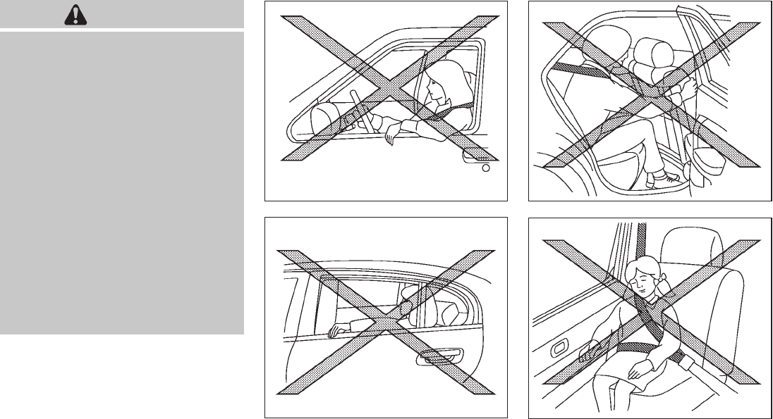
Black plate (63,1)
Model "Z51-D" EDITED: 2009/ 8/ 3
WARNING
.Never let children ride unrestrained
or extend their hands or face out of
the window. Do not attempt to hold
them in your lap or arms. Some
examples of dangerous riding posi-
tions are shown in the illustrations.
.Children may be severely injured or
killed when the front air bags, side
air bags or curtain and rollover air
bags inflate if they are not properly
restrained. Pre-teens and children
should be properly restrained in the
rear seat, if possible.
.Even with the NISSAN Advanced Air
Bag System, never install a rear-
facing child restraint in the front
seat. An inflating front air bag could
seriously injure or kill your child.
See “CHILD RESTRAINTS” earlier in
this section for details.
SSS0059A
Do not lean against doors or windows.
SSS0188A
SSS0140
SSS0162
Safety — Seats, seat belts and supplemental restraint system 1-49

Black plate (64,1)
Model "Z51-D" EDITED: 2009/ 8/ 3
SSS0159
WARNING
Front seat-mounted side-impact sup-
plemental air bags and roof-mounted
curtain side-impact and rollover supple-
mental air bags:
.The side air bags and curtain and
rollover air bags ordinarily will not
inflate in the event of a frontal
impact, rear impact or lower severity
side collision. Always wear your
seat belts to help reduce the risk
or severity of injury in various kinds
of accidents.
.The seat belts, the side air bags and
curtain and rollover air bags are
most effective when you are sitting
well back and upright in the seat
with both feet on the floor. The side
air bag and curtain and rollover air
bag inflate with great force. Do not
allow anyone to place their hand,
leg or face near the side air bag on
the side of the seatback of the front
seat or near the side roof rails. Do
not allow anyone sitting in the front
seats or rear outboard seats to
extend their hand out of the window
or lean against the door. Some
examples of dangerous riding posi-
tions are shown in the previous
illustrations.
.When sitting in the rear seat, do not
hold onto the seatback of the front
seat. If the side air bag inflates, you
may be seriously injured. Be espe-
cially careful with children, who
should always be properly re-
strained. Some examples of danger-
ous riding positions are shown in
the illustrations.
.Do not use seat covers on the front
seatbacks. They may interfere with
side air bag inflation.
1-50 Safety — Seats, seat belts and supplemental restraint system
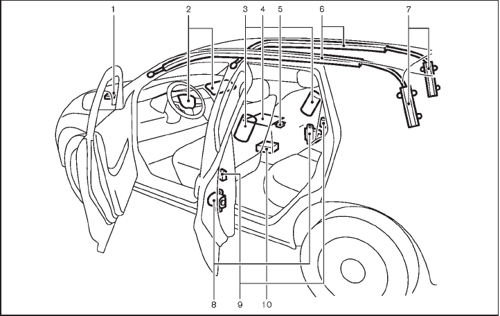
Black plate (65,1)
Model "Z51-D" EDITED: 2009/ 8/ 3
SSS0847
1. Crash zone sensor
2. Supplemental front-impact air bag modules
3. Front seat-mounted side-impact supplemental air
bag modules
4. Occupant classification sensor (pattern sensor)
5. Occupant classification system control unit
6. Roof-mounted curtain side-impact and rollover
supplemental air bags
7. Roof-mounted curtain side-impact and rollover
supplemental air bag inflators
8. Seat belt pretensioners
9. Satellite sensors
10. Air bag Control Unit (ACU)
NISSAN ADVANCED AIR BAG SYS-
TEM (front seats)
This vehicle is equipped with the NISSAN
Advanced Air Bag System for the driver and
front passenger seats. This system is designed
to meet certification requirements under U.S.
regulations. It is also permitted in Canada.
However, all of the information, cautions
and warnings in this manual still apply and
must be followed.
The driver supplemental front-impact air bag is
located in the center of the steering wheel; the
passenger supplemental front-impact air bag is
mounted in the instrument panel above the glove
box. The front air bags are designed to inflate in
higher severity frontal collisions, although they
may inflate if the forces in another type of
collision are similar to those of a higher severity
frontal impact. They may not inflate in certain
frontal collisions. Vehicle damage (or lack of it) is
not always an indication of proper front air bag
operation.
The NISSAN Advanced Air Bag System has
dual stage air bag inflators. The system monitors
information from the crash zone sensor, satellite
sensor, Air bag Control Unit (ACU), seat belt
buckle sensors and occupant classification
sensor (pattern sensor). Inflator operation is
based on the severity of a collision and seat belt
usage for the driver. For the front passenger, the
occupant classification sensor is also monitored.
Safety — Seats, seat belts and supplemental restraint system 1-51

Black plate (66,1)
Model "Z51-D" EDITED: 2009/ 8/ 3
Based on information from the sensors, only one
front air bag may inflate in a crash, depending on
the crash severity and whether the front
occupants are belted or unbelted. Additionally,
the front passenger air bag may be automatically
turned OFF under some conditions, depending
on the information provided by the occupant
classification sensor. If the front passenger air
bag is OFF, the passenger air bag status light
will be illuminated (if the seat is unoccupied, the
light will not be illuminated, but the air bag will
be off). (See “Front passenger air bag and
status light” later in this section for further
details.) One front air bag inflating does not
indicate improper performance of the system.
If you have any questions about your air bag
system, contact NISSAN or a NISSAN dealer. If
you are considering modification of your vehicle
due to a disability, you may also contact
NISSAN. Contact information is contained in
the front of this Owner’s Manual.
When a front air bag inflates, a fairly loud noise
may be heard, followed by release of smoke.
This smoke is not harmful and does not indicate
a fire. Care should be taken not to inhale it, as it
may cause irritation and choking. Those with a
history of a breathing condition should get fresh
air promptly.
Front air bags, along with the use of seat belts,
help to cushion the impact force on the head
and chest of the front occupants. They can help
save lives and reduce serious injuries. However,
an inflating front air bag may cause facial
abrasions or other injuries. Front air bags do
not provide restraint to the lower body.
Even with NISSAN Advanced Air Bags, seat
belts should be correctly worn and the driver
and passenger seated upright as far as practical
away from the steering wheel or instrument
panel. The front air bags inflate quickly in order
to help protect the front occupants. Because of
this, the force of the front air bag inflating can
increase the risk of injury if the occupant is too
close to, or is against, the air bag module during
inflation.
The front air bags will deflate quickly after a
collision.
The front air bags operate only when the
ignition switch is in the ON position.
After pushing the ignition switch to the ON
position, the supplemental air bag warning
light illuminates. The supplemental air bag
warning light will turn off after about 7
seconds if the system is operational.
SSS0823
Front passenger air bag status light
Front passenger air bag and status light
WARNING
The front passenger air bag is designed
to automatically turn OFF under some
conditions. Read this section carefully
to learn how it operates. Proper use of
the seat, seat belt and child restraints is
necessary for most effective protection.
Failure to follow all instructions in this
manual concerning the use of seats,
seat belts and child restraints can
increase the risk or severity of injury in
an accident.
1-52 Safety — Seats, seat belts and supplemental restraint system

Black plate (67,1)
Model "Z51-D" EDITED: 2009/ 8/ 3
Status light:
The front passenger air bag status light
is located on the instrument panel below the air
conditioner controls. The light operates as
follows:
.Unoccupied passenger seat: The
light is OFF and the front passenger air bag
is OFF and will not inflate in a crash.
.Passenger’s seat occupied by a small adult,
child or child restraint as outlined in this
section: The light illuminates to
indicate that the front passenger air bag is
OFF and will not inflate in a crash.
.Occupied passenger seat and the passen-
ger meets the conditions outlined in this
section: The light is OFF to indicate
that the front passenger air bag is opera-
tional.
Front passenger air bag:
The front passenger air bag is designed to
automatically turn OFF when the vehicle is
operated under some conditions as described
below as permitted by U.S. regulations. If the
front passenger air bag is OFF, it will not inflate
in a crash. The driver air bag and other air bags
in your vehicle are not part of this system.
The purpose of the regulation is to help reduce
the risk of injury or death from an inflating air bag
to certain front passenger seat occupants, such
as children, by requiring the air bag to be
automatically turned OFF.
The occupant classification sensor (pattern
sensor) is in the front passenger seat cushion
and is designed to detect an occupant and
objects on the seat. For example, if a child is in
the front passenger seat, the Advanced Air Bag
System is designed to turn the passenger air
bag OFF in accordance with the regulations.
Also, if a child restraint of the type specified in
the regulations is on the seat, the occupant
classification sensor can detect it and cause the
air bag to turn OFF.
Front passenger seat adult occupants who are
properly seated and using the seat belt as
outlined in this manual should not cause the
passenger air bag to be automatically turned
OFF. For small adults it may be turned OFF,
however, if the occupant does not sit in the seat
properly (for example, by not sitting upright, by
sitting on an edge of the seat, or by otherwise
being out of position), this could cause the
sensor to turn the air bag OFF. Always be sure
to be seated and wearing the seat belt properly
for the most effective protection by the seat belt
and supplemental air bag.
NISSAN recommends that pre-teens and chil-
dren be properly restrained in a rear seat.
NISSAN also recommends that appropriate
child restraints and booster seats be properly
installed in a rear seat. If this is not possible, the
occupant classification sensor is designed to
operate as described above to turn the front
passenger air bag OFF for specified child
restraints. Failing to properly secure child
restrains and to use the Automatic Locking
Retractor (ALR) mode (child restraint mode)
may allow the restraint to tip or move in an
accident or sudden stop. This can also result in
the passenger air bag inflating in a crash instead
of being OFF. (See “CHILD RESTRAINTS”
earlierinthissectionforproperuseand
installation.)
If the front passenger seat is not occupied, the
passenger air bag is designed not to inflate in a
crash. However, heavy objects placed on the
seat could result in air bag inflation, because of
the object being detected by the occupant
classification sensor. Other conditions could
also result in air bag inflation, such as if a child is
standing on the seat, or if two children are on the
seat, contrary to the instructions in this manual.
Always be sure that you and all vehicle
occupants are seated and restrained properly.
Using the passenger air bag status light, you can
monitor when the front passenger air bag is
automatically turned OFF with the seat occu-
pied. The light will not illuminate when the front
passenger seat is unoccupied.
If an adult occupant is in the seat but the
passenger air bag status light is illuminated
Safety — Seats, seat belts and supplemental restraint system 1-53

Black plate (68,1)
Model "Z51-D" EDITED: 2009/ 8/ 3
(indicating that the air bag is OFF), it could be
that the person is a small adult, or is not sitting
on the seat properly.
If a child restraint must be used in the front seat,
the passenger air bag status light may or may
not be illuminated, depending on the size of the
child and the type of child restraint being used. If
the air bag status light is not illuminated
(indicating that the air bag might inflate in a
crash), it could be that the child restraint or seat
belt is not being used properly. Make sure that
the child restraint is installed properly, the seat
belt is used properly and the occupant is
positioned properly. If the air bag status light is
not illuminated, reposition the occupant or child
restraint in a rear seat.
If the passenger air bag status light will not
illuminate even though you believe that the child
restraint, the seat belts and the occupant are
properly positioned, the system may be sensing
an unoccupied seat (in which case the air bag is
OFF). Your NISSAN dealer can check that the
system is OFF by using a special tool. However,
until you have confirmed with your dealer that
your air bag is working properly, reposition the
occupant or child restraint in a rear seat.
The air bag system and passenger air bag status
light will take a few seconds to register a change
in the passenger seat status. However, if the
seat becomes unoccupied, the air bag status
light will remain off.
If a malfunction occurs in the front passenger air
bag system, the supplemental air bag warning
light , located in the meter and gauges area,
will blink. Have the system checked by a
NISSAN dealer.
Other supplemental front-impact air bag
precautions
WARNING
.Do not place any objects on the
steering wheel pad or on the instru-
ment panel. Also, do not place any
objects between any occupant and
the steering wheel or instrument
panel. Such objects may become
dangerous projectiles and cause
injury if the front air bags inflate.
.Do not place objects with sharp
edges on the seat. Also, do not
place heavy objects on the seat that
will leave permanent impressions in
the seat. Such objects can damage
the seat or occupant classification
sensor (pattern sensor). This can
affect the operation of the air bag
system and result in serious perso-
nal injury.
.Do not use water or acidic cleaners
(hot steam cleaners) on the seat.
This can damage the seat or occu-
pant classification sensor. This can
also affect the operation of the air
bag system and result in serious
personal injury.
.Immediately after inflation, several
front air bag system components
will be hot. Do not touch them; you
may severely burn yourself.
.No unauthorized changes should be
made to any components or wiring
of the supplemental air bag system.
This is to prevent accidental infla-
tion of the supplemental air bag or
damage to the supplemental air bag
system.
.Do not make unauthorized changes
to your vehicle’s electrical system,
suspension system or front end
structure. This could affect proper
operation of the front air bag sys-
tem.
.Tampering with the supplemental
air bag system may result in serious
personal injury. Tampering includes
changes to the steering wheel and
the instrument panel assembly by
1-54 Safety — Seats, seat belts and supplemental restraint system
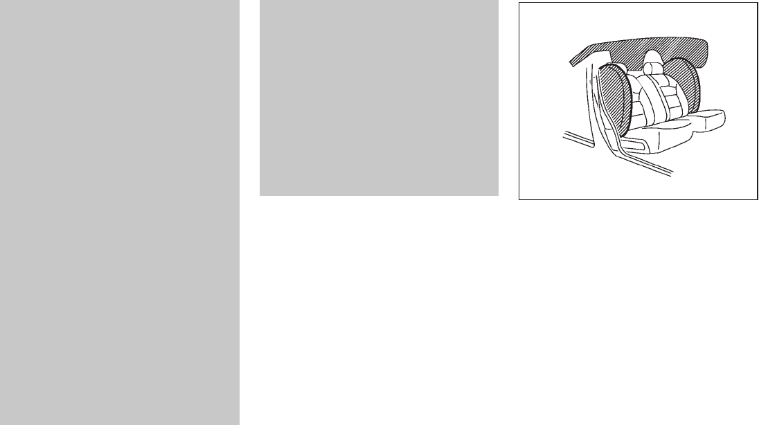
Black plate (69,1)
Model "Z51-D" EDITED: 2009/ 8/ 3
placing material over the steering
wheel pad and above the instrument
panel or by installing additional trim
material around the air bag system.
.Modifying or tampering with the
front passenger seat may result in
serious personal injury. For exam-
ple, do not change the front seats by
placing material on the seat cushion
or by installing additional trim ma-
terial, such as seat covers, on the
seat that is not specifically designed
to assure proper air bag operation.
Additionally, do not stow any ob-
jects under the front passenger seat
or the seat cushion and seatback.
Such objects may interfere with the
proper operation of the occupant
classification sensor.
.No unauthorized changes should be
made to any components or wiring
of the seat belt system. This may
affect the front air bag system.
Tampering with the seat belt system
may result in serious personal in-
jury.
.Work on and around the front air
bag system should be done by a
NISSAN dealer. Installation of elec-
trical equipment should also be
done by a NISSAN dealer. The
Supplemental Restraint System
(SRS) wiring harnesses* should not
be modified or disconnected. Un-
authorized electrical test equipment
and probing devices should not be
used on the air bag system.
.A cracked windshield should be
replaced immediately by a qualified
repair facility. A cracked windshield
could affect the function of the
supplemental air bag system.
*The SRS wiring harness connectors are
yellow and orange for easy identifica-
tion.
When selling your vehicle, we request that you
inform the buyer about the front air bag system
and guide the buyer to the appropriate sections
in this Owner’s Manual.
SSS0848
FRONT SEAT-MOUNTED SIDE-IM-
PACT SUPPLEMENTAL AIR BAG AND
ROOF-MOUNTED CURTAIN SIDE-IM-
PACT AND ROLLOVER SUPPLEMEN-
TAL AIR BAG SYSTEMS
The side air bags are located in the outside of
the seatback of the front seats. The curtain and
rollover air bags are located in the side roof rails.
These systems are designed to meet voluntary
guidelines to help reduce the risk of injury to out-
of-position occupants. However, all of the
information, cautions and warnings in this
manual still apply and must be followed.
The side air bags and curtain and rollover air
bags are designed to inflate in higher severity
Safety — Seats, seat belts and supplemental restraint system 1-55

Black plate (70,1)
Model "Z51-D" EDITED: 2009/ 8/ 3
side collisions, although they may inflate if the
forces in another type of collision are similar to
those of a higher severity side impact. They are
designed to inflate on the side where the vehicle
is impacted. They may not inflate in certain side
collisions. Curtain and rollover air bags are also
designed to inflate in certain types of rollover
collisions or near rollovers.
Vehicle damage (or lack of it) is not always an
indication of proper side air bag and curtain and
rollover air bag operation.
When the side air bags and curtain and rollover
air bags inflate, a fairly loud noise may be heard,
followed by release of smoke. This smoke is not
harmful and does not indicate a fire. Care should
be taken not to inhale it, as it may cause irritation
and choking. Those with a history of a breathing
condition should get fresh air promptly.
Side air bags, along with the use of seat belts,
help to cushion the impact force on the chest
and pelvic area of the front occupants. Curtain
and rollover air bags help to cushion the impact
force to the head of occupants in the front and
rear outboard seating positions. They can help
save lives and reduce serious injuries. However,
side air bags and curtain and rollover air bags
may cause abrasions or other injuries. Side air
bags and curtain and rollover air bags do not
provide restraint to the lower body.
The seat belts should be correctly worn and the
driver and passenger seated upright as far as
practical away from the side air bags. Rear seat
passengers should be seated as far away as
practical from the door finishers and side roof
rails. The side air bags and curtain and rollover
air bags inflate quickly in order to help protect
the occupants in the outboard seating positions.
Because of this, the force of the side air bags
and curtain and rollover air bags inflating can
increase the risk of injury if the occupant is too
close to, or is against, these air bag modules
during inflation. The side air bags and curtain
and rollover air bags will deflate quickly after the
collision is over.
The side air bags and curtain and rollover
air bags operate only when the ignition
switch is in the ON position.
After pushing the ignition switch to the ON
position, the supplemental air bag warning
light illuminates. The supplemental air bag
warning light will turn off after about 7
seconds if the systems are operational.
WARNING
.Do not place any objects near the
seatback of the front seats. Also, do
not place any objects (an umbrella,
bag, etc.) between the front door
finisher and the front seat. Such
objects may become dangerous
projectiles and cause injury if a side
air bag inflates.
.Right after inflation, several side air
bag and curtain and rollover air bag
system components will be hot. Do
not touch them; you may severely
burn yourself.
.No unauthorized changes should be
made to any components or wiring
of this side air bag and curtain and
rollover air bags. This is to prevent
damage to or accidental inflation of
the side-impact air bag and curtain
side-impact and rollover air bag
systems.
.Do not make unauthorized changes
to your vehicle’s electrical system,
suspension system or side panel.
This could affect proper operation
of the side air bag and curtain and
rollover air bag systems.
.Tampering with the supplemental
air bag system may result in serious
personal injury. For example, do not
change the front seats by placing
material near the seatbacks or by
installing additional trim material,
1-56 Safety — Seats, seat belts and supplemental restraint system

Black plate (71,1)
Model "Z51-D" EDITED: 2009/ 8/ 3
such as seat covers, around the side
air bag.
.Work around and on the side air bag
and curtain and rollover air bag
systems should be done by a
NISSAN dealer. Installation of elec-
trical equipment should also be
done by a NISSAN dealer. The
Supplemental Restraint System
(SRS) wiring harnesses* should not
be modified or disconnected. Un-
authorized electrical test equipment
and probing devices should not be
used on the side air bag and curtain
and rollover air bag systems.
*The SRS wiring harness connectors are
yellow and orange for easy identifica-
tion.
When selling your vehicle, we request that you
inform the buyer about the side air bag and
curtain and rollover air bag systems and guide
the buyer to the appropriate sections in this
Owner’s Manual.
SEAT BELTS WITH PRETENSIONERS
(front seats)
WARNING
.The pretensioners cannot be reused
after activation. They must be re-
placed together with the retractor
and buckle as a unit.
.If the vehicle becomes involved in a
frontal collision but a pretensioner
is not activated, be sure to have the
pretensioner system checked and, if
necessary, replaced by a NISSAN
dealer.
.No unauthorized changes should be
made to any components or wiring
of the pretensioner system. This is
to prevent damage to or accidental
activation of the pretensioners.
Tampering with the pretensioner
system may result in serious perso-
nal injury.
.Work around and on the preten-
sioner system should be done by a
NISSAN dealer. Installation of elec-
trical equipment should also be
done by a NISSAN dealer. Un-
authorized electrical test equipment
and probing devices should not be
used on the pretensioner system.
.If you need to dispose of a preten-
sioner or scrap the vehicle, contact a
NISSAN dealer. Correct preten-
sioner disposal procedures are set
forthintheappropriateNISSAN
Service Manual. Incorrect disposal
procedures could cause personal
injury.
The pretensioner system activates in conjunc-
tion with the front air bag system. The preten-
sioner system also activates with the curtain and
rollover air bags in certain types of rollover
collisions or near rollovers. Working with the
seat belt retractor, it helps tighten the seat belt
when the vehicle becomes involved in certain
types of collisions, helping to restrain front seat
occupants.
The pretensioner is encased with the seat belt
retractor. These seat belts are used the same
way as conventional seat belts.
When a pretensioner activates, smoke is re-
leased and a loud noise may be heard. The
smoke is not harmful and does not indicate a
fire. Care should be taken not to inhale it, as it
may cause irritation and choking. Those with a
history of a breathing condition should get fresh
air promptly.
Safety — Seats, seat belts and supplemental restraint system 1-57

Black plate (72,1)
Model "Z51-D" EDITED: 2009/ 8/ 3
After pretensioner activation, load limiters allow
the seat belt to release webbing (if necessary) to
reduce forces against the chest.
If any abnormality occurs in the pretensioner
system, the supplemental air bag warning light
will not come on, will flash intermittently or
will turn on for 7 seconds and remain on after
the ignition switch has been pushed to the ON
position. In this case, the pretensioner may not
function properly. They must be checked and
repaired. Take your vehicle to the nearest
NISSAN dealer.
When selling your vehicle, we request that you
inform the buyer about the pretensioner system
and guide the buyer to the appropriate sections
in this Owner’s Manual.
SSS1016
SUPPLEMENTAL AIR BAG WARNING
LABELS
Warning labels about the supplemental front-
impact air bag system are placed in the vehicle
as shown in the illustration.
SRS air bag
The warning labels *
1are located on the
surface of the sun visors.
SPA1097
SUPPLEMENTAL AIR BAG WARNING
LIGHT
The supplemental air bag warning light, display-
ing in the instrument panel, monitors the
circuits of the supplemental front-impact air bag,
front seat-mounted side-impact supplemental
air bag, roof-mounted curtain side-impact and
rollover supplemental air bag and seat belt
pretensioner systems. The monitored circuits
include Air bag Control Unit (ACU), crash zone
sensor, satellite sensors, occupant classification
system, front air bag modules, side air bag
modules, curtain and rollover air bag modules,
pretensioners and all related wiring.
When the ignition switch is in the ON position,
1-58 Safety — Seats, seat belts and supplemental restraint system

Black plate (73,1)
Model "Z51-D" EDITED: 2009/ 8/ 3
the supplemental air bag warning light illumi-
nates for about 7 seconds and then turns off.
This means the system is operational.
If any of the following conditions occur, the front
air bag, side air bag, curtain and rollover air bag
and pretensioner systems need servicing:
.The supplemental air bag warning light
remains on after approximately 7 seconds.
.The supplemental air bag warning light
flashes intermittently.
.The supplemental air bag warning light does
not come on at all.
Under these conditions, the front air bag, side air
bag, curtain and rollover air bag and preten-
sioner systems may not operate properly. It must
be checked and repaired. Take your vehicle to
the nearest NISSAN dealer.
WARNING
If the supplemental air bag warning
light is on, it could mean that the front
air bag, side air bag, curtain and roll-
over air bag and/or pretensioner sys-
tems will not operate in an accident. To
help avoid injury to yourself or others,
have your vehicle checked by a NISSAN
dealer as soon as possible.
REPAIR AND REPLACEMENT PRO-
CEDURE
The front air bags, side air bags, curtain and
rollover air bags and pretensioners are designed
to activate on a one-time-only basis. As a
reminder, unless it is damaged, the supplemen-
tal air bag warning light will remain illuminated
after inflation has occurred. Repair and replace-
ment of these systems should be done only by a
NISSAN dealer.
When maintenance work is required on the
vehicle, the front air bags, side air bags, curtain
and rollover air bags and pretensioners and
related parts should be pointed out to the
person performing the maintenance. The ignition
switch should always be in the LOCK position
when working under the hood or inside the
vehicle.
WARNING
.Once a front air bag, side air bag or
curtain and rollover air bag has
inflated, the air bag module will
not function again and must be
replaced. Additionally, if any of the
front air bags inflate, the activated
pretensioners must also be re-
placed. The air bag module and
pretensioner system should be re-
placed by a NISSAN dealer. The air
bag modules and pretensioner sys-
tem cannot be repaired.
.The front air bag, side air bag and
curtain and rollover air bag systems,
and pretensioner system should be
inspected by a NISSAN dealer if
there is any damage to the front
end or side portion of the vehicle.
.If you need to dispose of a supple-
mental air bag or pretensioner sys-
tems, or scrap the vehicle, contact a
NISSAN dealer. Correct supplemen-
tal air bag and pretensioner system
disposal procedures are set forth in
theappropriateNISSANService
Manual. Incorrect disposal proce-
dures could cause personal injury.
Safety — Seats, seat belts and supplemental restraint system 1-59

Black plate (7,1)
2 Instruments and controls
Model "Z51-D" EDITED: 2009/ 8/ 3
Instrument panel ................................................ 2-2
Meters and gauges............................................. 2-4
Speedometer and odometer ............................. 2-5
Tachometer................................................... 2-6
Engine coolant temperature gauge ..................... 2-6
Fuel gauge ................................................... 2-7
Compass (if so equipped) .................................... 2-7
Zone variation change procedure ....................... 2-9
Warning/indicator lights and audible reminders ....... 2-10
Checking bulbs ........................................... 2-10
Warning lights ............................................. 2-10
Indicator lights............................................. 2-14
Audible reminders ........................................ 2-16
Dot matrix liquid crystal display............................ 2-17
Indicators for operation.................................. 2-18
Indicators for maintenance.............................. 2-20
Trip computer.............................................. 2-21
Security systems.............................................. 2-25
Vehicle security system (if so equipped) ............ 2-25
NISSAN Vehicle Immobilizer System ................. 2-27
Windshield wiper and washer switch .................... 2-28
Rain-sensing auto wiper system
(if so equipped) ........................................... 2-29
Rear window wiper and washer switch.................. 2-30
Rear window and outside mirror defroster switch..... 2-31
Headlight and turn signal switch .......................... 2-32
Xenon headlights (if so equipped) .................... 2-32
Headlight switch .......................................... 2-32
Turn signal switch ........................................ 2-35
Fog light switch (if so equipped)...................... 2-35
Hazard warning flasher switch............................. 2-36
Horn ............................................................. 2-36
Heated seats (if so equipped) ............................. 2-37
Clock ............................................................ 2-38
Models without color display........................... 2-38
Models with color display............................... 2-38
Vehicle Dynamic Control (VDC) OFF switch ........... 2-39
Power outlet ................................................... 2-39
Cigarette lighter and ashtray (if so equipped).......... 2-40
Storage ......................................................... 2-41
Cup holders................................................ 2-41
Sunglasses holder........................................ 2-42
Glove box .................................................. 2-43
Console box ............................................... 2-43
Storage box (if so equipped) .......................... 2-44
Cargo floor box ........................................... 2-45
Luggage side box......................................... 2-45
Cargo cover (if so equipped) .......................... 2-45
Luggage hooks............................................ 2-46
Roof rack (if so equipped).............................. 2-47
Coat hooks................................................. 2-48

Black plate (8,1)
Model "Z51-D" EDITED: 2009/ 8/ 3
Windows ....................................................... 2-48
Power windows ........................................... 2-48
Moonroof (if so equipped) .................................. 2-51
Automatic moonroof and sunshades ................. 2-51
Interior lights ................................................... 2-53
Map lights .................................................. 2-53
Personal lights............................................. 2-53
Interior light control switch ............................. 2-53
Mood lights .................................................... 2-54
Vanity mirror lights............................................ 2-55
Cargo lights.................................................... 2-55
HomeLink®Universal Transceiver (if so equipped) .... 2-55
Programming HomeLink®............................... 2-56
Programming HomeLink®for Canadian
customers .................................................. 2-57
Operating the HomeLink®Universal
Transceiver ................................................. 2-58
Programming trouble-diagnosis ....................... 2-58
Clearing the programmed information................ 2-58
Reprogramming a single HomeLink®button ........ 2-58
If your vehicle is stolen .................................. 2-58

Black plate (76,1)
Model "Z51-D" EDITED: 2009/ 8/ 3
SSI0627
1. Side ventilator
2. Power lift gate switch*
3. Headlight, fog light* and turn signal switch
4. Fuel-filler door opener switch
5. Steering-wheel-mounted controls (left side)*
— Audio control*
— Bluetooth®Hands-Free Phone System control*
6. Meters and gauges
7. Steering wheel
— Horn
— Driver supplemental air bag
— Power steering system
8. Steering-wheel-mounted controls (right side)
— Cruise control switches
9. Wiper and washer switch
10. Push-button ignition switch
11. Center ventilator
12. Center display/Center color display*/Navigation
system**
13. Heater/air conditioner or
Center multi-function control panel*
— Navigation system**
— Vehicle information and setting buttons
— Bluetooth®Hands-Free Phone System
— Audio system
14. Hazard warning flasher switch
15. Front passenger supplemental air bag
16. Vehicle Dynamic Control (VDC) OFF switch
17. Hood release handle
18. Power lift gate main switch
19. Power seatback switch*
20. Fuse box cover
21. Parking brake
22. Tilting telescopic steering wheel lever or switch
23. Intelligent Key port
24. Audio system
— Clock
25. Heated seat switch*
26. Selector lever
27. Front passenger air bag status light
INSTRUMENT PANEL
2-2 Instruments and controls
Black plate (77,1)
Model "Z51-D" EDITED: 2009/ 8/ 3
28. Power outlet
29. All-Wheel Drive (AWD) LOCK switch*
30. Rear window and outside mirror* defroster switch
31. Heater/air conditioner control or Audio system
32. Glove box
*: if so equipped
**: Refer to the separate Navigation System Owner’s
Manual (if so equipped).
Instruments and controls 2-3

Black plate (78,1)
Model "Z51-D" EDITED: 2009/ 8/ 3
SSI0377
1. Instrument brightness control switch
2. Tachometer
3. Speedometer
4. Fuel gauge
5. Warning/indicator lights
6. Trip computer switch
7. Dot matrix liquid crystal display
8. Engine coolant temperature gauge
9. Vehicle information display
— Odometer/twin trip odometer
— Continuously Variable Transmission (CVT)
position indicator
10. RESET switch for trip odometer
The needle indicators may move slightly
after the ignition switch is pushed to the
LOCK position. This is not a malfunction.
METERS AND GAUGES
2-4 Instruments and controls
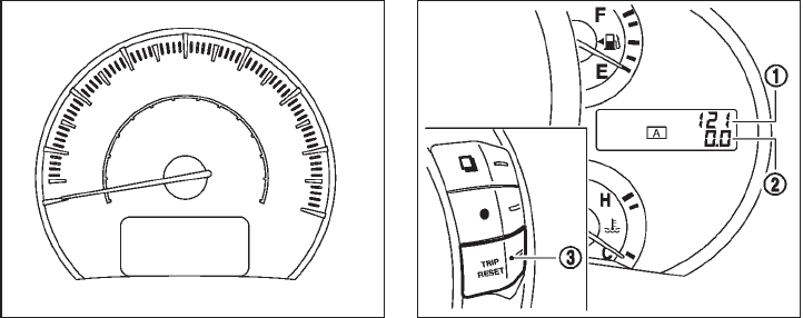
Black plate (79,1)
Model "Z51-D" EDITED: 2009/ 8/ 3
SIC3571
Speedometer
SPEEDOMETER AND ODOMETER
Speedometer
The speedometer indicates vehicle speed in
miles per hour (MPH) and kilometers per hour
(km/h).
SIC3572
Odometer/twin trip odometer
Odometer/twin trip odometer
The odometer *
1and twin trip odometer *
2
are displayed when the ignition switch is in the
ON position.
The odometer records the total distance the
vehicle has been driven.
The twin trip odometer records the distance of
individual trips.
Changing the display:
Pushing the TRIP A/B RESET switch *
3on the
right side of the combination meter panel
changes the display as follows:
TRIP A ?TRIP B ?TRIP A
Resetting the trip odometer:
Pushing the TRIP A/B RESET switch *
3for
more than 1 second resets the trip odometer to
zero.
Instruments and controls 2-5

Black plate (80,1)
Model "Z51-D" EDITED: 2009/ 8/ 3
SIC3573
TACHOMETER
The tachometer indicates engine speed in
revolutions per minute (RPM). Do not rev the
engine into the red zone *
1.
CAUTION
When engine speed approaches the red
zone, shift to a higher gear or reduce
engine speed. Operating the engine in
the red zone may cause serious engine
damage.
SIC3574
ENGINE COOLANT TEMPERATURE
GAUGE
The gauge indicates the engine coolant tem-
perature.
The engine coolant temperature is within the
normal range when the gauge needle points
within the zone *
1shown in the illustration.
The engine coolant temperature varies with the
outside air temperature and driving conditions.
CAUTION
If the gauge indicates engine coolant
temperature near the hot (H) end of the
normal range, reduce vehicle speed to
decrease temperature. If gauge is over
the normal range, stop the vehicle as
soon as safely possible. If the engine is
overheated, continued operation of the
vehicle may seriously damage the en-
gine. See “IF YOUR VEHICLE OVER-
HEATS” in the “6. In case of emergency”
section for immediate action required.
2-6 Instruments and controls

Black plate (81,1)
Model "Z51-D" EDITED: 2009/ 8/ 3
SIC3575
FUEL GAUGE
The gauge indicates the approximate fuel level
in the tank.
The gauge may move slightly during braking,
turning, acceleration, or going up or down hills.
The gauge needle returns to E (Empty) after the
ignition switch is pushed to the OFF position.
Refill the fuel tank before the gauge
registers “E” (Empty).
The low fuel warning appears on the dot
matrix liquid crystal display when the fuel tank is
getting low. Refuel as soon as it is convenient,
preferably before the gauge reaches “E”. There
will be a small reserve of fuel in the tank when
the fuel gauge needle reaches “E”.
The indicates that the fuel-filler door is
located on the driver’s side of the vehicle.
CAUTION
.If the vehicle runs out of fuel, the
malfunction indicator light
(MIL) may come on. Refuel as soon
as possible. After a few driving trips,
the light should turn off. If the
light remains on after a few driving
trips, have the vehicle inspected by
a NISSAN dealer.
.For additional information, see
“Malfunction Indicator Light (MIL)”
later in this section.
SIC3181
When the ignition switch is pushed to the ON
position, the compass display *
Bwill indicate
the direction of the vehicle’s heading.
COMPASS (if so equipped)
Instruments and controls 2-7
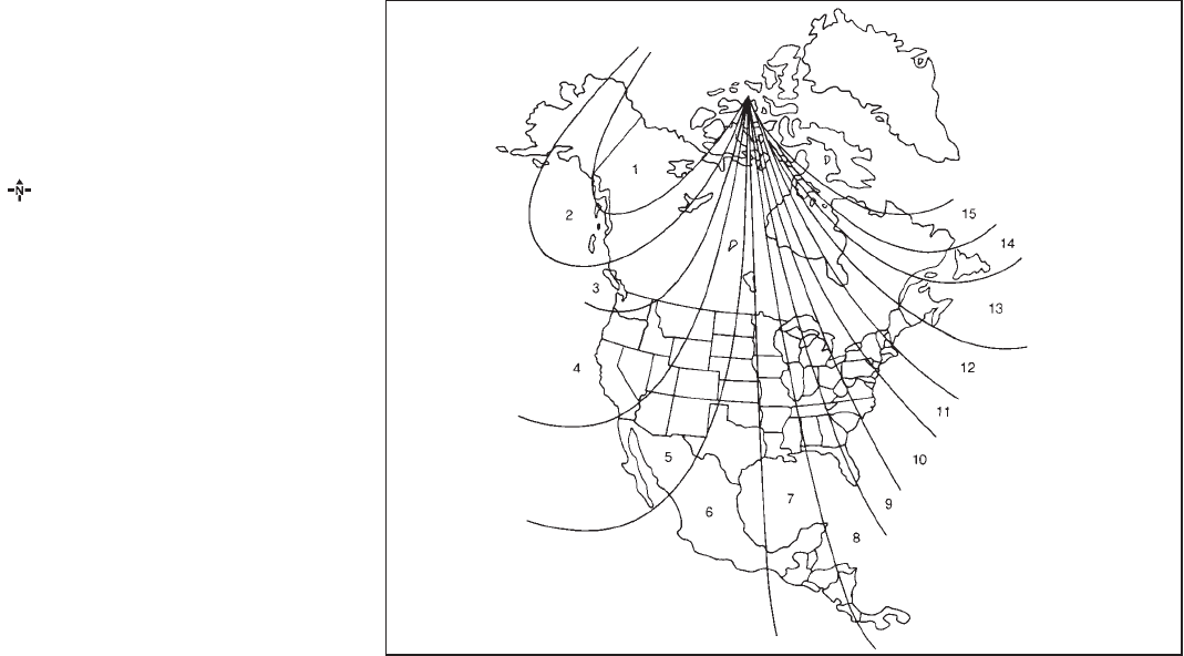
Black plate (82,1)
Model "Z51-D" EDITED: 2009/ 8/ 3
If the display reads “C”, calibrate the compass
by driving the vehicle in 3 complete circles at
less than 5 MPH (8 km/h). You can also
calibrate the compass by driving your vehicle
on your everyday route. The compass will be
calibrated once it has tracked 3 complete
circles.
To turn on and off the compass manually, push
the switch *
Awhile the ignition switch is in
the ON position.
SIC0611B
Zone map
2-8 Instruments and controls

Black plate (83,1)
Model "Z51-D" EDITED: 2009/ 8/ 3
ZONE VARIATION CHANGE PROCE-
DURE
The difference between magnetic north and
geographical north is known as variance. In
some areas, this difference can sometimes be
great enough to cause false compass readings.
Follow these instructions to set the variance for
your particular location if this happens:
1. Push the switch for more than 3
seconds. The current zone number will
appear in the display.
2. Find your current location and variance
number on the zone map.
NOTE:
Use zone number 5 for Hawaii.
3. Push the switch repeatedly until the
new zone number appears in the display,
then release the switch. After you release
the switch, the display will show a compass
direction within a few seconds.
.If the compass deviates from the correct
indication soon after repeated adjust-
ment, have the compass checked at a
NISSAN dealer.
.The compass may not indicate the
correct compass point in tunnels or
while driving up or down a steep hill.
(The compass returns to the correct com-
pass point when the vehicle moves to an
area where the geomagnetism is stabilized.)
CAUTION
.Do not install a ski rack, antenna,
etc., which are attached to the
vehicle by means of a magnet. They
affect the operation of the compass.
.When cleaning the mirror, use a
paper towel or similar material
dampened with glass cleaner. Do
not spray glass cleaner directly on
the mirror as it may cause the liquid
cleaner to enter the mirror housing.
Instruments and controls 2-9
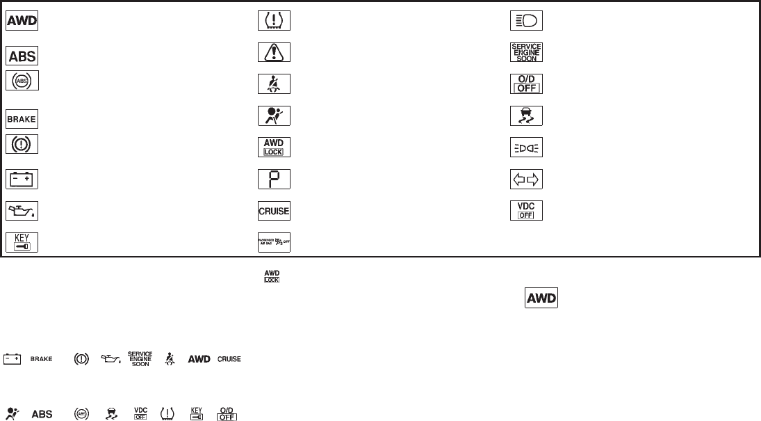
Black plate (84,1)
Model "Z51-D" EDITED: 2009/ 8/ 3
All-Wheel Drive (AWD) warning light (AWD
models)* Low tire pressure warning light High beam indicator light
Anti-lock Braking System (ABS) warning
light
Master warning light Malfunction Indicator Light (MIL)
Seat belt warning light Overdrive off indicator light
Brake warning light
Supplemental air bag warning light Slip indicator light
All-Wheel Drive (AWD) LOCK indicator light
(AWD models)* Small light indicator light
Charge warning light Continuously Variable Transmission (CVT)
position indicator light Turn signal/hazard indicator lights
Engine oil pressure warning light Cruise indicator light Vehicle Dynamic Control (VDC) off indicator
light
Intelligent Key warning light Front passenger air bag status light *: if so equipped
CHECKING BULBS
With all doors closed, apply the parking brake
and push the ignition switch to the ON position
without starting the engine. The following lights
will come on (if so equipped):
, or , , , , ,
The following lights come on briefly and then go
off (if so equipped):
, or , , , , , ,
If any light does not come on, it may indicate a
burned-out bulb or an open circuit in the
electrical system. Have the system checked by
a NISSAN dealer.
Some indicators and warnings are also dis-
played on the dot matrix crystal display on the
speedometer. (See “DOT MATRIX LIQUID
CRYSTAL DISPLAY” later in this section.)
WARNING LIGHTS
All-Wheel Drive (AWD) warning
light (AWD models)
The light comes on when the ignition switch is
pushed to ON. It turns off soon after the engine
is started.
If the AWD system malfunctions, or the diameter
of the front and the rear wheels are different, the
warning light will either remain illuminated or
WARNING/INDICATOR LIGHTS AND
AUDIBLE REMINDERS
2-10 Instruments and controls

Black plate (85,1)
Model "Z51-D" EDITED: 2009/ 8/ 3
blink. (See “ALL-WHEEL DRIVE (AWD)” in the
“5. Starting and driving” section.)
CAUTION
.If the warning light comes on while
driving there may be a malfunction
in the AWD system. Reduce the
vehicle speed and have your vehicle
checked by a NISSAN dealer as
soon as possible.
.If the AWD warning light blinks
when you are driving:
— blinks rapidly (about twice a
second):
Pull off the road in a safe area,
and idle the engine. The driving
mode will change to 2WD to
prevent the AWD system from
malfunctioning. If the warning
light turns off, you can drive
again.
— blinks slowly (about once every
2 seconds):
Pull off the road in a safe area,
and idle the engine. Check that
all tire sizes are the same, tire
pressure is correct and tires are
not worn.
.If the warning light is still on after
the above operations, have your
vehicle checked by a NISSAN dealer
as soon as possible.
or Anti-lock Braking System
(ABS) warning light
When the ignition switch is in the ON position,
the Anti-lock Braking System (ABS) warning
light illuminates and then turns off. This indicates
the ABS is operational.
If the ABS warning light illuminates while the
engine is running, or while driving, it may
indicate the ABS is not functioning properly.
Have the system checked by a NISSAN dealer.
If an ABS malfunction occurs, the anti-lock
function is turned off. The brake system then
operates normally, but without anti-lock assis-
tance. (See “BRAKE SYSTEM” in the “5.
Starting and driving” section.)
or Brake warning light
This light functions for both the parking brake
and the foot brake systems.
Parking brake indicator:
When the ignition switch is in the ON position,
the light comes on when the parking brake is
applied.
Low brake fluid warning light:
When the ignition switch is in the ON position,
the light warns of a low brake fluid level. If the
light comes on while the engine is running with
the parking brake not applied, stop the vehicle
and perform the following:
1. Check the brake fluid level. Add brake fluid
as necessary. (See “BRAKE FLUID” in the
“8. Maintenance and do-it-yourself” sec-
tion.)
2. If the brake fluid level is correct, have the
warningsystemcheckedbyaNISSAN
dealer.
Anti-lock Braking System (ABS) warning
indicator:
When the parking brake is released and the
brake fluid level is sufficient, if both the brake
warning light and the Anti-lock Braking System
(ABS) warning light illuminate, it may indicate
the ABS is not functioning properly. Have the
brake system checked, and if necessary re-
paired, by a NISSAN dealer promptly. (See
“Anti-lock Braking System (ABS) warning light”
earlier in this section.)
Instruments and controls 2-11

Black plate (86,1)
Model "Z51-D" EDITED: 2009/ 8/ 3
WARNING
.Your brake system may not be
working properly if the warning light
is on. Driving could be dangerous. If
you judge it to be safe, drive care-
fully to the nearest service station
for repairs. Otherwise, have your
vehicle towed because driving it
could be dangerous.
.Pressing the brake pedal with the
engine stopped and/or low brake
fluid level may increase your stop-
ping distance and braking will re-
quire greater pedal effort as well as
pedal travel.
.If the brake fluid level is below the
minimum or MIN mark on the brake
fluid reservoir, do not drive until the
brake system has been checked at a
NISSAN dealer.
Charge warning light
If the light comes on while the engine is running,
it may indicate the charging system is not
functioning properly. Turn the engine off and
check the alternator belt. If the belt is loose,
broken, missing or if the light remains on, see a
NISSAN dealer immediately.
CAUTION
Do not continue driving if the alternator
belt is loose, broken or missing.
Engine oil pressure warning light
This light warns of low engine oil pressure. If the
light flickers or comes on during normal driving,
pull off the road in a safe area, stop the engine
immediately and call a NISSAN dealer or other
authorized repair shop.
The engine oil pressure warning light is
not designed to indicate a low oil level.
Use the dipstick to check the oil level. (See
“ENGINE OIL” in the “8. Maintenance and do-it-
yourself” section.)
CAUTION
Running the engine with the engine oil
pressure warning light on could cause
serious damage to the engine almost
immediately. Such damage is not cov-
ered by warranty. Turn off the engine as
soon as it is safe to do so.
Intelligent Key warning light
After the ignition switch is pushed to the ON
position, this light comes on for about 2 seconds
and then turns off.
This light warns of a malfunction with the
electrical steering lock system (if so equipped)
or the Intelligent Key system.
If the light comes on while the engine is
stopped, it may be impossible to free the
steering lock (if so equipped) or to start the
engine. If the light comes on while the engine is
running, you can drive the vehicle. However in
these cases, contact a NISSAN dealer for repair
as soon as possible.
Low tire pressure warning light
Your vehicle is equipped with a Tire Pressure
Monitoring System (TPMS) that monitors the tire
pressure of all tires except the spare.
The low tire pressure warning light warns of low
tire pressure or indicates that the TPMS is not
functioning properly.
After the ignition switch is pushed ON, this light
illuminates for about 1 second and turns off.
2-12 Instruments and controls

Black plate (87,1)
Model "Z51-D" EDITED: 2009/ 8/ 3
Low tire pressure warning:
If the vehicle is being driven with low tire
pressure, the warning light will illuminate.
When the low tire pressure warning light
illuminates, you should stop and adjust the tire
pressure to the recommended COLD tire
pressure shown on the Tire and Loading
Information label. The low tire pressure warning
light does not automatically turn off when the tire
pressure is adjusted. After the tire is inflated to
the recommended pressure, the vehicle must be
driven at speeds above 16 MPH (25 km/h) to
activate the TPMS and turn off the low tire
pressure warning light. Use a tire pressure
gauge to check the tire pressure.
For additional information, see “TIRE PRES-
SURE MONITORING SYSTEM (TPMS)” in the
“5. Starting and driving” section and “TIRE
PRESSURE MONITORING SYSTEM (TPMS)”
in the “6. In case of emergency” section.
TPMS malfunction:
If the TPMS is not functioning properly, the low
tire pressure warning light will flash for approxi-
mately 1 minute when the ignition switch is
pushed ON. The light will remain on after the 1
minute. Have the system checked by a NISSAN
dealer.
For additional information, see “TIRE PRES-
SURE MONITORING SYSTEM (TPMS)” in the
“5. Starting and driving” section.
WARNING
.If the light does not illuminate with
the ignition switch pushed ON, have
the vehicle checked by a NISSAN
dealer as soon as possible.
.If the light illuminates while driving,
avoid sudden steering maneuvers or
abrupt braking, reduce vehicle
speed, pull off the road to a safe
location and stop the vehicle as
soon as possible. Driving with un-
der-inflated tires may permanently
damage the tires and increase the
likelihood of tire failure. Serious
vehicle damage could occur and
may lead to an accident and could
result in serious personal injury.
Check the tire pressure for all four
tires. Adjust the tire pressure to the
recommended COLD tire pressure
shownontheTireandLoading
Information label to turn the low
tire pressure warning light OFF. If
the light stays on after adjusting the
tire pressure and driving over 16
MPH (25 km/h), have the system
checked by a NISSAN dealer. If you
have a flat tire, replace it with a
spare tire as soon as possible.
.When a spare tire is mounted or a
wheel is replaced, the TPMS will not
function and the low tire pressure
warning light will flash for approxi-
mately 1 minute. The light will
remain on after 1 minute. Contact
your NISSAN dealer as soon as
possible for tire replacement and/
or system resetting.
.Replacing tires with those not ori-
ginally specified by NISSAN could
affect the proper operation of the
TPMS.
CAUTION
.The TPMS is not a substitute for the
regular tire pressure check. Be sure
to check the tire pressure regularly.
.If the vehicle is being driven at
speeds of less than 16 MPH (25
km/h), the TPMS may not operate
correctly.
.Be sure to correctly install the
specified size of tires to the four
Instruments and controls 2-13

Black plate (88,1)
Model "Z51-D" EDITED: 2009/ 8/ 3
wheels.
Master warning light
When the ignition switch is in the ON position,
the master warning light illuminates if any of the
following are displayed on the dot matrix liquid
crystal display:
.No key warning
.Low fuel warning
.Low washer fluid warning
.Parking brake release warning
.Door/lift gate open warning
See “DOT MATRIX LIQUID CRYSTAL DIS-
PLAY” later in this section.
Seat belt warning light
The light and chime remind you to fasten seat
belts. The light illuminates whenever the ignition
switch is pushed to the ON position, and will
remain illuminated until the driver’s seat belt is
fastened.
The seat belt warning light for the front
passenger will illuminate if the seat belt is not
fastened when the front passenger’s seat is
occupied. For 6 seconds after the ignition
switch is in the ON position, the system does
not activate the warning light for the front
passenger.
See “SEAT BELTS” in the “1. Safety — Seats,
seat belts and supplemental restraint system”
section for precautions on seat belt usage.
Supplemental air bag warning light
After pushing the ignition switch to the ON
position, the supplemental air bag warning light
will illuminate. The supplemental air bag warning
light will turn off after about 7 seconds if the
supplemental front air bag and supplemental
side air bag, curtain side-impact air bag systems
and/or pretensioner seat belt are operational.
If any of the following conditions occur, the front
air bag, side air bag, curtain and rollover air bag
and pretensioner systems needs servicing and
your vehicle must be taken to your nearest
NISSAN dealer.
.The supplemental air bag warning light
remains on after approximately 7 seconds.
.The supplemental air bag warning light
flashes intermittently.
.The supplemental air bag warning light does
not come on at all.
Unless checked and repaired, the Supplemental
Restraint Systems (air bag systems) and/or the
pretensioners may not function properly.
For additional information, see “SUPPLEMEN-
TAL RESTRAINT SYSTEM” in the “1. Safety —
Seats, seat belts and supplemental restraint
system” section.
WARNING
If the supplemental air bag warning
light is on, it could mean that the front
air bag, side air bag, curtain and roll-
over air bag and/or pretensioner sys-
tems will not operate in an accident. To
help avoid injury to yourself or others,
have your vehicle checked by a NISSAN
dealer as soon as possible.
INDICATOR LIGHTS
All-Wheel Drive (AWD) LOCK
indicator light (AWD models)
This light illuminates when the ignition switch is
turned to the ON position, and turns off within 1
second.
When selecting the LOCK mode while the
engine is running, this light will illuminate. (See
“ALL-WHEEL DRIVE (AWD)” in the “5. Starting
and driving” section.)
2-14 Instruments and controls

Black plate (89,1)
Model "Z51-D" EDITED: 2009/ 8/ 3
Continuously Variable Transmis-
sion (CVT) position indicator light
When the ignition switch is pushed to the ON
position, the indicator shows the automatic
selector shift position. (See “CONTINUOUSLY
VARIABLE TRANSMISSION (CVT)” in the “5.
Starting and driving” section.)
Cruise indicator light
Cruise main switch indicator:
This light illuminates when the cruise control
main switch is pushed. The light turns off when
the main switch is pushed again. When the
cruise main switch indicator light illuminates, the
cruise control system is operational. (See
“CRUISE CONTROL” in the “5. Starting and
driving” section.)
Cruise malfunction:
If the cruise indicator light blinks while the
engine is running, it may indicate the cruise
control system is not functioning properly. Have
the system checked by a NISSAN dealer. (See
“CRUISE CONTROL” in the “5. Starting and
driving” section.)
Front passenger air bag status
light
The front passenger air bag status light
will be lit and the passenger front air bag will be
OFF depending on how the front passenger
seat is being used.
For front passenger air bag status light opera-
tion,see“NISSANADVANCEDAIRBAG
SYSTEM (front seats)” in the “1. Safety —
Seats, seat belts and supplemental restraint
system” section of this manual.
High beam indicator light (Blue)
This light comes on when the headlight high
beam is on and goes out when the low beam is
selected.
Malfunction Indicator Light (MIL)
If the malfunction indicator light comes on
steady or blinks while the engine is running, it
may indicate a potential emission control and/or
Continuously Variable Transmission (CVT) mal-
function.
The malfunction indicator light may also come on
steady if the fuel-filler cap is loose or missing, or
if the vehicle runs out of fuel. Check to make
sure the fuel-filler cap is installed and closed
tightly, and that the vehicle has at least 3 US
gallons (11.4 liters) of fuel in the fuel tank.
After a few driving trips, the light should
turn off if no other potential emission control
system malfunction exists.
If this indicator light remains on for 20 seconds
and then blinks for 10 seconds when the engine
is not running, it indicates that the vehicle is not
ready for an emission control system inspection/
maintenance test. (See “READINESS FOR
INSPECTION/MAINTENANCE (I/M) TEST” in
the “9. Technical and consumer information”
section.)
Operation:
The malfunction indicator light will come on in
one of two ways:
.Malfunction indicator light on steady — An
emission control system and/or CVT mal-
function has been detected. Check the fuel-
filler cap. If the fuel-filler cap is loose or
missing, tighten or install the cap and
continue to drive the vehicle. The light
should turn off after a few driving trips. If the
light does not turn off after a few
driving trips, have the vehicle inspected by a
NISSAN dealer. You do not need to have
your vehicle towed to the dealer.
.Malfunction indicator light blinking — An
engine misfire has been detected which may
Instruments and controls 2-15

Black plate (90,1)
Model "Z51-D" EDITED: 2009/ 8/ 3
damage the emission control system.
To reduce or avoid emission control system
damage:
a) Do not drive at speeds above 45 MPH
(72 km/h).
b) Avoid hard acceleration or deceleration.
c) Avoid steep uphill grades.
d) If possible, reduce the amount of cargo
being hauled or towed.
The malfunction indicator light may stop
blinking and remain on.
Have the vehicle inspected by a NISSAN
dealer. You do not need to have your vehicle
towed to the dealer.
CAUTION
Continued vehicle operation without
having the emission control system
and/or CVT system checked and re-
paired as necessary could lead to poor
driveability, reduced fuel economy, and
possible damage to the emission con-
trol system.
Overdrive off indicator light
The overdrive off indicator light illuminates when
the overdrive off mode is selected.
For additional information, see ““CONTINU-
OUSLY VARIABLE TRANSMISSION (CVT)” in
the “5. Starting and driving” section of this
manual.
Slip indicator light
This light will blink when the Vehicle Dynamic
Control (VDC) system is operating, thus alerting
the driver that the vehicle is nearing its traction
limits. The road surface may be slippery.
Small light indicator light
The light comes on when the front park, side
marker, tail and license plate lights are on.
Turn signal/hazard indicator lights
The light flashes when the turn signal switch
lever or hazard switch is turned on.
Vehicle Dynamic Control (VDC) off
indicator light
The light comes on when the Vehicle Dynamic
Control (VDC) off switch is pushed to OFF. This
indicates that the VDC system is not operating.
When the VDC off indicator light and slip
indicator light come on with the VDC system
turned on, this light alerts the driver to the fact
that the VDC system’s fail-safe mode is operat-
ing, for example the VDC system may not be
functioning properly. Have the system checked
by a NISSAN dealer. If a malfunction occurs in
the system, the VDC system function will be
canceled but the vehicle is still driveable. For
additional information, see “VEHICLE DYNAMIC
CONTROL (VDC) SYSTEM” in the “5. Starting
and driving” section of this manual.
AUDIBLE REMINDERS
Key reminder chime
A chime will sound if the driver side door is
opened while the ignition switch is pushed to
the ACC position or pushed to the OFF or
LOCK position with the Intelligent Key left in the
Intelligent Key port. Make sure the ignition
switch is pushed to the OFF position, and take
the Intelligent Key with you when leaving the
vehicle.
2-16 Instruments and controls

Black plate (91,1)
Model "Z51-D" EDITED: 2009/ 8/ 3
Light reminder chime
A chime will sound when the driver side door is
opened with the light switch in the or
position and the ignition switch in the ACC
or OFF position.
Turn the light switch off when you leave the
vehicle.
Parking brake reminder chime
The chime will sound if the vehicle is driven with
the parking brake applied. Stop the vehicle and
release the parking brake.
Seat belt warning chime
The chime will sound for about 6 seconds
unless the driver’s seat belt is securely fastened.
Brake pad wear warning
The disc brake pads have audible wear warn-
ings. When a brake pad requires replacement, it
will make a high pitched scraping sound when
the vehicle is in motion. This scraping sound will
first occur only when the brake pedal is
depressed. After more wear of the brake pad,
the sound will always be heard even if the brake
pedal is not depressed. Have the brakes
checked as soon as possible if the warning
sound is heard.
SIC3576
The dot matrix liquid crystal display *
1is
located in the speedometer, and it displays,
the key operation information and other warn-
ings and information.
For the detail about the Intelligent Key System,
see “INTELLIGENT KEY SYSTEM” in the “3.
Pre-driving checks and adjustments” section.
DOT MATRIX LIQUID CRYSTAL
DISPLAY
Instruments and controls 2-17

Black plate (92,1)
Model "Z51-D" EDITED: 2009/ 8/ 3
SIC3577
INDICATORS FOR OPERATION
1. Engine start operation indicator
This indicator appears when the selector lever is
in the P (Park) position.
This indicator means that the engine will start by
pushing the ignition switch with the brake pedal
depressed.
You can start the engine directly in any position.
2. Steering lock release malfunction
indicator (if so equipped)
This indicator appears when the steering wheel
cannot be released from the LOCK position.
If this indicator appears, push the push-button
ignition switch while lightly turning the steering
2-18 Instruments and controls
Black plate (93,1)
Model "Z51-D" EDITED: 2009/ 8/ 3
wheel right and left.
3. Key insertion indicator
This indicator appears when the key needs to be
inserted into the key port.
If this indicator appears, insert the key into the
key port in the correct direction. (See “PUSH-
BUTTON IGNITION SWITCH” in the “5. Start-
ing and driving” section.)
4. Key removal indicator
This indicator appears when the driver’s door is
opened with the ignition switch in the OFF or
LOCK position and the key placed in the key
port. A key reminder chime also sounds.
If this indicator appears, remove the key from the
key port and take it with you when leaving the
vehicle.
5. NO KEY warning
This warning appears in either of the following
conditions.
No key inside the vehicle:
The warning appears when the door is closed
with the Intelligent Key left outside the vehicle
and the ignition switch in the ACC or ON
position. Make sure that the Intelligent Key is
inside the vehicle.
Unregistered key:
The warning appears when the ignition switch is
pushed from the LOCK position and the key
cannot be recognized by the system. You cannot
start the engine with an unregistered key. Use
the registered key.
See “INTELLIGENT KEY SYSTEM” in the “3.
Pre-driving checks and adjustments” section for
more details.
6. SHIFT “P” warning
This warning appears when the ignition switch is
pushed to stop the engine with the selector lever
in any position except the P (Park) position.
If this warning appears, move the selector lever
to the P (Park) position or push the ignition
switch to the ON position.
An inside warning chime will also sound. (See
“INTELLIGENT KEY SYSTEM” in the “3. Pre-
driving checks and adjustments” section.)
7. “PUSH” warning
This warning appears when the selector lever is
moved to the P (Park) position with the ignition
switch in the ACC position after the SHIFT “P”
warning appears.
To push the ignition switch to the OFF position,
perform the following procedure:
SHIFT “P” warning ?(Move the selector
lever to “P”) ?PUSH warning ?(Push
the ignition switch ?ignition switch position
is turned to ON) ?PUSH warning ?
(Push the ignition switch ?ignition switch
position is turned to OFF)
8. Key battery discharge indicator
This indicator appears when the key battery is
running out of power.
If this indicator appears, replace the battery with
a new one. (See “BATTERY REPLACEMENT” in
the “8. Maintenance and do-it-yourself” section.)
9. Parking brake release warning
This warning appears when the vehicle speed is
above 4 MPH (7 km/h) and the parking brake is
applied.
10. Low fuel warning
This warning appears when the fuel level in the
tank is getting low. Refuel as soon as it is
convenient, preferably before the fuel gauge
reaches the empty (E) position.
There is a small reserve of fuel remaining
in the tank when the fuel gauge reaches
the empty (E) position.
Instruments and controls 2-19
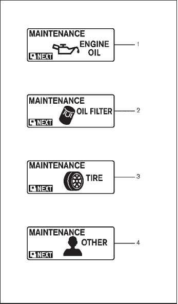
Black plate (94,1)
Model "Z51-D" EDITED: 2009/ 8/ 3
11. Low washer fluid warning
This warning appears when the washer tank fluid
is at a low level. Add washer fluid as necessary.
(See “WINDOW WASHER FLUID” in the “8.
Maintenance and do-it-yourself” section.)
12. Door/lift gate open warning (ignition
switch is in the ON position)
This warning appears if any of the doors and/or
the lift gate are open or not closed securely. The
vehicle icon indicates which door is open on the
display.
13. “Time to rest” indicator
This indicator appears when the set “time to
rest” indicator activates. You can set the time for
up to 6 hours. (See “TRIP COMPUTER” later in
this section.)
14. Low outside temperature warning
This warning appears if the outside temperature
is below 378F(38C). The warning can be set not
to be displayed. (See “TRIP COMPUTER” later
in this section.)
SIC3578
INDICATORS FOR MAINTENANCE
1. Engine oil replacement indicator
This indicator appears when the set time comes
for changing the engine oil. You can set or reset
the distance for changing the engine oil. (See
“TRIP COMPUTER” later in this section.)
2. Oil filter replacement indicator
This indicator appears when the set time comes
for replacing the oil filter. You can set or reset
the distance for replacing the oil filter. (See
“TRIP COMPUTER” later in this section.)
3. Tire replacement indicator
This indicator appears when the set time comes
for replacing tires. You can set or reset the
distance for replacing tires. (See “TRIP COM-
PUTER” later in this section.)
4. “OTHER” indicator
This indicator appears when the set time comes
for replacing items other than the engine oil, oil
filter and tires. You can set or reset the distance
for replacing the items. (See “TRIP COMPU-
TER” later in this section.)
More maintenance reminders are also available
on the center display. (See “HOW TO USE
INFO BUTTON” in the “4. Monitor, heater, air
conditioner, audio, phone and voice recognition
systems” section.)
2-20 Instruments and controls

Black plate (95,1)
Model "Z51-D" EDITED: 2009/ 8/ 3
SIC3580
TRIP COMPUTER
Switches for the trip computer are located on
the right side of the combination meter panel. To
operate the trip computer, push the side or front
of the switches as shown above.
*
Aswitch
*
Bswitch
When the ignition switch is pushed to the ON
position, modes of the trip computer can be
selected by pushing the switch *
A.
Each time the switch *
Ais pushed, the
display will change as follows:
Current fuel consumption ?Average fuel
consumption and speed ?Elapsed time and
trip odometer ?Distance to empty (dte) ?
Outside air temperature (ICY) ?Setting ?
Warning check
SIC3673
Current fuel consumption
The current fuel consumption mode shows the
current fuel consumption.
Instruments and controls 2-21

Black plate (96,1)
Model "Z51-D" EDITED: 2009/ 8/ 3
SIC3674
Average fuel consumption (MPG or l
(liter)/100 km) and speed (MPH or km/h)
Fuel consumption:
The average fuel consumption mode shows the
average fuel consumption since the last reset.
Resetting is done by pushing the switch *
B
for longer than 1 second. (The average speed is
also reset at the same time.)
The display is updated every 30 seconds. At
about the first 1/3 mile (500 m) after a reset, the
display shows “——”.
Speed:
The average speed mode shows the average
vehicle speed since the last reset. Resetting is
done by pushing the switch *
Bfor longer
than 1 second. (The average fuel consumption is
also reset at the same time.)
The display is updated every 30 seconds. The
first 30 seconds after a reset, the display shows
“——”.
SIC3675
Elapsed time and trip odometer (mls or
km)
Elapsed time:
The elapsed time mode shows the time since
the last reset. The displayed time can be reset
by pushing the switch *
Bfor longer than
1 second. (The trip odometer is also reset at the
same time.)
Trip odometer:
The trip odometer mode shows the total
distance the vehicle has been driven since the
last reset. Resetting is done by pushing the
switch *
Bfor longer than 1 second. (The
elapsed time is also reset at the same time.)
2-22 Instruments and controls

Black plate (104,1)
Model "Z51-D" EDITED: 2009/ 8/ 3
.High — High sensitive operation
.Low — Low sensitive operation
To turn the rain-sensing auto wiper system off,
push up the lever to the OFF position, or pull
down the lever to the LO or HI position.
CAUTION
Do not touch the rain sensor and
around it when the wiper switch is in
the INT position and the ignition switch
is in the ON position. The wipers may
operate unexpectedly and cause to an
injury or a wiper damage.
.The rain-sensing auto wipers are in-
tended for use during rain. If the switch
is left in the INT position, the wipers
may operate unexpectedly when dirt,
fingerprints, oil film or insects are stuck
on or around the sensor. The wipers
may also operate when exhaust gas or
moisture affect the rain sensor.
.The rain-sensing auto wipers may not
operate if rain does not hit the rain
sensor even if it is raining.
WARNING
In freezing temperatures the washer
solution may freeze on the rear window
glass and obscure your vision. Warm
the rear window with the defroster
before you wash the rear window.
CAUTION
.Do not operate the washer continu-
ously for more than 30 seconds.
.Do not operate the washer if the
reservoir tank is empty.
.Do not fill the window washer
reservoir tank with washer fluid
concentrates at full strength. Some
methyl alcohol based washer fluid
concentrates may permanently stain
the grille if spilled while filling the
window washer reservoir tank.
.Pre-mix washer fluid concentrates
with water to the manufacturer’s
recommended levels before pouring
the fluid into the window washer
reservoir tank. Do not use the
window washer reservoir tank to
mix the washer fluid concentrate
and water.
If the rear window wiper operation is
interrupted by snow or ice, the wiper may
stop moving to protect its motor. If this
occurs, turn the wiper switch to the OFF
position and remove the snow or ice that is
on and around the wiper arms. In approxi-
mately 1 minute, turn the switch on again
to operate the wiper.
REAR WINDOW WIPER AND
WASHER SWITCH
2-30 Instruments and controls

Black plate (110,1)
Model "Z51-D" EDITED: 2009/ 8/ 3
SIC2574
Push the switch on to warn other drivers when
you must stop or park under emergency condi-
tions. All turn signal lights will flash.
WARNING
.If stopping for an emergency, be
sure to move the vehicle well off the
road.
.Do not use the hazard warning
flashers while moving on the high-
way unless unusual circumstances
force you to drive so slowly that
your vehicle might become a hazard
to other traffic.
.Turn signals do not work when the
hazard warning flasher lights are
on.
The flasher can be actuated with the ignition
switch in any position.
Some state laws may prohibit the use of
the hazard warning flasher switch while
driving.
SIC3586
To sound the horn, push the pad area *
Aof the
steering wheel.
WARNING
Do not disassemble the horn. Doing so
could affect proper operation of the
supplemental front air bag system.
Tampering with the supplemental front
air bag system may result in serious
personal injury.
HAZARD WARNING FLASHER
SWITCH HORN
2-36 Instruments and controls
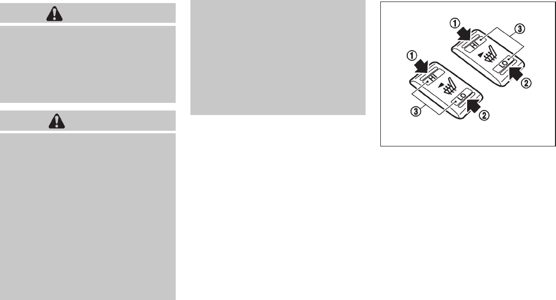
Black plate (111,1)
Model "Z51-D" EDITED: 2009/ 8/ 3
WARNING
Do not use or allow occupants to use
the seat heater if you or the occupants
cannot monitor elevated seat tempera-
tures or have an inability to feel pain in
body parts that contact the seat. Use of
the seat heater by such people could
result in serious injury.
CAUTION
.The battery could run down if the
seat heater is operated while the
engine is not running.
.Do not use the seat heater for
extended periods or when no one
is using the seat.
.Do not put anything on the seat
which insulates heat, such as a
blanket, cushion, seat cover, etc.
Otherwise, the seat may become
overheated.
.Do not place anything hard or heavy
on the seat or pierce it with a pin or
similar object. This may result in
damage to the heater.
.Any liquid spilled on the heated seat
should be removed immediately
with a dry cloth.
.When cleaning the seat, never use
gasoline, thinner, or any similar
materials.
.If any malfunctions are found or the
heated seat does not operate, turn
the switch off and have the system
checked by a NISSAN dealer.
SIC2770
The seats are warmed by built-in heaters. The
switches located on the center console and rear
doors (if so equipped for rear seats) can be
operated independently of each other.
1. Start the engine.
2. Select heat range.
*
1For high heat, push the HI (High) side of
the switch.
*
2For low heat, push the LO (Low) side of
the switch.
The indicator light in the switch *
3will
illuminate when the heater is on.
HEATED SEATS (if so equipped)
Instruments and controls 2-37
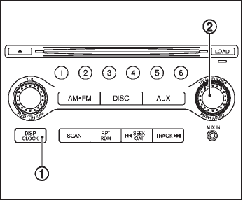
Black plate (112,1)
Model "Z51-D" EDITED: 2009/ 8/ 3
3. To turn off the heater, return the switch to
the level position. Make sure the indicator
light goes off.
The heater is controlled by a thermostat,
automatically turning the heater on and off.
The indicator light will remain on as long as
the switch is on.
When the vehicle’s interior is warmed, or
before you leave the vehicle, be sure to turn
off the switch.
SIC3649
MODELS WITHOUT COLOR DISPLAY
The digital clock (in the audio unit) displays the
time when the ignition switch is in the ACC or
ON position.
Adjusting the time
1. Push and hold the CLOCK button *
1for
more than 2 seconds until the display shows
“Hour Adjust”.
2. Turn the AUDIO knob *
2to adjust hours.
3. Push the CLOCK button *
1or AUDIO
knob *
2to enter. The display will show
“Minute Adjust”.
4. Turn the AUDIO knob *
2to adjust minutes.
5. Push the CLOCK button *
1or AUDIO
knob *
2to enter.
The display will return to the regular clock
display after 10 seconds.
If the power supply is disconnected, the clock
will not indicate the correct time.
Readjust the time.
MODELS WITH COLOR DISPLAY
For adjusting the time, see “Clock settings” in
the “4. Monitor, heater, air conditioner, audio,
phone and voice recognition systems” section.
CLOCK
2-38 Instruments and controls

Black plate (114,1)
Model "Z51-D" EDITED: 2009/ 8/ 3
To use the power outlet, pull the cover as
illustrated.
CAUTION
.The outlet and plug may be hot
during or immediately after use.
.Do not use with accessories that
exceed a 12 volt, 120W (10A) power
draw. Do not use double adapters or
more than one electrical accessory.
.Use power outlet with the engine
running to avoid discharging the
vehicle battery.
.Avoid using power outlet when the
air conditioner, headlights or rear
window defroster is on.
.This power outlet is not designed
for use with a cigarette lighter unit.
.Push the plug in as far as it will go.
If good contact is not made, the plug
may overheat or the internal tem-
perature fuse may open.
.Before inserting or disconnecting a
plug, be sure the electrical acces-
sory being used is turned OFF.
.When not in use, be sure to close
the cap. Do not allow water to
contact the outlet.
SIC3588
To open the ashtray lid, push the lid down and
release it *
1.
To empty the ashtray, pull out *
2.
The cigarette lighter operates when the ignition
switch is in the ON position.
Push the lighter in all the way *
3, then release
it. When the lighter is heated, it will spring out.
Return the lighter to its original position after
use.
CIGARETTE LIGHTER AND
ASHTRAY (if so equipped)
2-40 Instruments and controls

Black plate (118,1)
Model "Z51-D" EDITED: 2009/ 8/ 3
SIC3591
Rear
To open, push the knob *
1and pull out *
2.
SIC3593
STORAGE BOX (if so equipped)
To open, push the storage box lid *
1as
illustrated.
The inner tray can be removed *
2as illustrated.
Do not place valuable items in the storage
box.
Do not use the storage box as an ashtray.
SIC3655
Type A
SIC3656
Type B
2-44 Instruments and controls
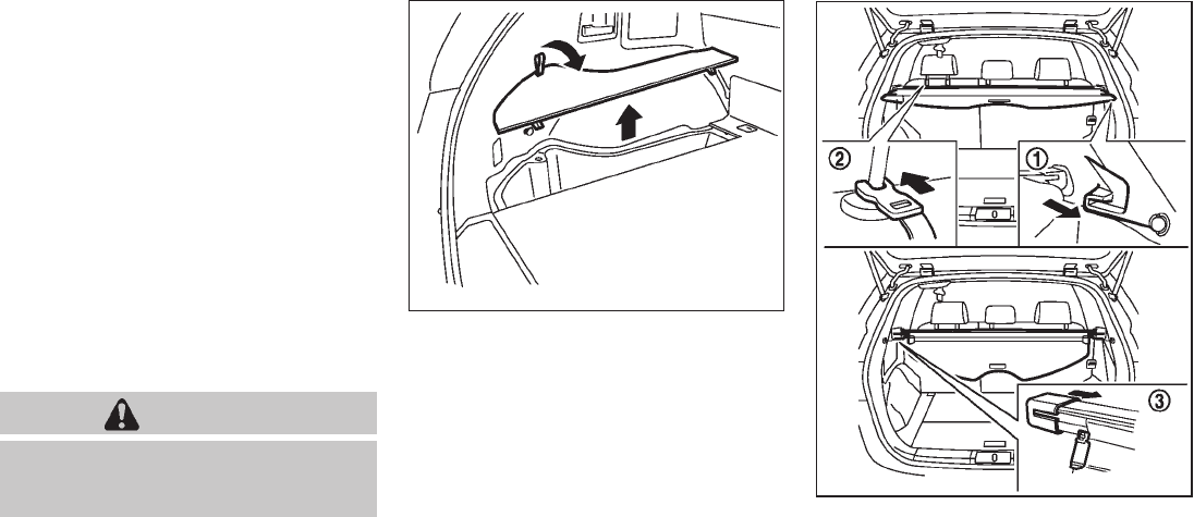
Black plate (119,1)
Model "Z51-D" EDITED: 2009/ 8/ 3
CARGO FLOOR BOX
Type A
1. To open the cargo floor box, pull the strap
*
A.
2. Remove the strap *
Bfrom the back side of
the board and hang it on the opening of the
lift gate.
Type B
To open the cargo floor box, push *
A. To close,
push the lid until the lock latches.
The net partitions can be removed *
Bto make
a larger storage space.
The cargo floor box needs to be removed when
you need a spare tire. (See “FLAT TIRE” in the
“6. In case of emergency” section.)
CAUTION
To avoid damage, do not load more
than 22 lbs (10 kg) of cargo into the
cargo floor box.
SIC3594
LUGGAGE SIDE BOX
To open the luggage side box, pull up the strap.
SIC3595
CARGO COVER (if so equipped)
The cargo cover keeps the contents in the cargo
area hidden from the outside.
To use the cargo cover, pull it out and hang both
sides on the hooks *
1.
Instruments and controls 2-45

Black plate (121,1)
Model "Z51-D" EDITED: 2009/ 8/ 3
ropes and hooks.
.Unsecured cargo can become dan-
gerous in an accident or sudden
stop.
CAUTION
Do not apply a total load of more than
22 lb (10 kg) *
Aor 7 lb (3 kg) *
Bto a
single hook.
SIC3597
ROOF RACK (if so equipped)
Always distribute the luggage evenly on the roof
rack. Do not load more than 165 lb (75 kg)
(black) or 220 lb (100 kg) (silver) on the roof
rails. Observe the maximum load limit shown on
the crossbars or roof carriers when you attach
them on the roof rails. Contact a NISSAN dealer
for crossbar or other equipment information. Be
careful that your vehicle does not exceed the
Gross Vehicle Weight Rating (GVWR) or its
Gross Axle Weight Rating (GAWR front and
rear). The GVWR and GAWR are located on the
F.M.V.S.S. or C.V.M.S.S. certification label (lo-
cated on the driver’s door pillar). For more
information regarding GVWR and GAWR, see
“VEHICLE LOADING INFORMATION” in the “9.
Technical and consumer information” section.
WARNING
.Drive extra carefully when the vehi-
cle is loaded at or near the cargo
carrying capacity, especially if the
significant portion of that load is
carried on the roof rack.
.Heavy loading of the roof rack has
the potential to affect the vehicle
stability and handling during sud-
den or unusual handling maneuvers.
.Roof rack load should be evenly
distributed.
.Do not exceed maximum roof rack
load weight capacity.
.Properly secure all cargo with ropes
or straps to help prevent it from
sliding or shifting. In a sudden stop
or collision, unsecured cargo could
cause personal injury.
CAUTION
Use care when placing or removing
items from the roof rack. If you cannot
comfortably lift the items onto the roof
Instruments and controls 2-47

Black plate (123,1)
Model "Z51-D" EDITED: 2009/ 8/ 3
SIC3283A
Main power window switch (driver’s
side)
1. Driver side window
2. Front passenger side window
3. Rear left passenger side window
4. Rear right passenger side window
5. Window lock button
To open or close the window, push down *
Aor
pull up *
Bthe switch and hold it. The main
switch (driver side switches) will open or close
all the windows.
Locking passengers’ windows
When the lock button *
Cis pushed in, only the
driver side window can be opened or closed.
Push it in again to cancel.
SIC3241
Passenger side power window switch
The passenger side switch will open or close
only the corresponding window. To open or
close the window, push down or pull up the
switch and hold it.
Instruments and controls 2-49
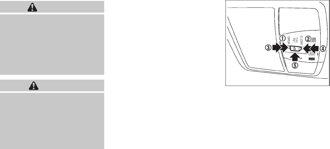
Black plate (125,1)
Model "Z51-D" EDITED: 2009/ 8/ 3
WARNING
.In an accident you could be thrown
from the vehicle through an open
moonroof. Always use seat belts
and child restraints.
.Do not allow anyone to stand up or
extend any portion of their body out
of the moonroof opening while the
vehicle is in motion or while the
moonroof is closing.
CAUTION
.Remove water drops, snow, ice or
sand from the moonroof before
opening.
.Do not place any heavy object on
the moonroof or surrounding area.
.Do not push or pull on the sun-
shade. Doing so can damage the
sunshade.
AUTOMATIC MOONROOF AND SUN-
SHADES
The moonroof and sunshades only operates
when the ignition switch is in the ON position.
The automatic moonroof and sunshades are
operational for about 45 seconds, even if the
ignition switch is pushed to the OFF position. If
the driver’s door or the passenger’s door is
opened during this period of about 45 seconds,
power to the moonroof and sunshades is
canceled.
SIC3598
Sliding sunshade and moonroof
When the OPEN side *
1of the moonroof
switch is pushed, the front and rear sunshades
will fully open. When the switch is pushed again,
the moonroof will fully open.
When the CLOSE side *
2of the moonroof
switch is pushed, the moonroof will automati-
cally close. Push the switch again, and the front
and rear sunshades will close.
When the OPEN or CLOSE side of the moon-
roof switch is pushed to the second detent (*
3
or *
4), both the sunshade and moonroof will
open or close.
To stop the sunshades or moonroof during the
MOONROOF (if so equipped)
Instruments and controls 2-51

Black plate (126,1)
Model "Z51-D" EDITED: 2009/ 8/ 3
operation, push either of the OPEN *
1, CLOSE
*
2or UP *
5of the switch.
Tilting moonroof
To tilt up the moonroof, push the moonroof
switch to the up position *
5.
To tilt down the moonroof, push the switch to the
up position *
5or push the CLOSE side *
2of
the switch.
When the moonroof is tilted up, push the
CLOSE side of the moonroof switch to the
second detent *
4. The moonroof will tilt down
and the sunshades will close.
Auto reverse function
WARNING
There are some small distances imme-
diately before the closed position which
cannot be detected. Make sure that all
passengers have their hands, etc., in-
side the vehicle before closing the
moonroof.
If the control unit detects something caught in
the moonroof and sunshades when they are
closing, the moonroof will be immediately
opened.
The auto reverse function can be activated when
the moonroof and sunshades are closed by
automatic operation when the ignition switch is
in the ON position or for about 45 seconds after
the ignition switch is pushed to the OFF
position.
If the moonroof and sunshades cannot be
closed automatically when the auto reverse
function activates due to a malfunction, push
and hold the CLOSE side *
2of the moonroof
switch.
Depending on the environment or driving
conditions, the auto reverse function may
be activated if an impact or load similar to
something being caught in the moonroof
occurs.
If the moonroof does not operate
If the moonroof does not operate properly,
perform the following procedure to initialize the
moonroof operation system.
1. If the moonroof is open, close it fully by
pushing the CLOSE side *
2of the moon-
roof switch.
2. Push and hold the CLOSE side *
2of the
moonroof switch.
3. Release the moonroof switch after the
moonroof or sunshade moves slightly to
the closed position.
4. Push and hold the CLOSE side *
2of the
moonroof switch for 10 seconds.
5. The moonroof and sunshades will fully open
and then close.
6. Check if the moonroof switch operates
normally.
If the moonroof does not operate properly after
performing the procedure above, have your
vehicle checked by a NISSAN dealer.
2-52 Instruments and controls
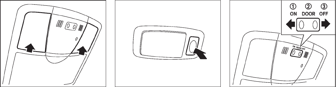
Black plate (127,1)
Model "Z51-D" EDITED: 2009/ 8/ 3
SIC3249
MAP LIGHTS
Push the button as illustrated to turn the light on
or off.
SIC3250
PERSONAL LIGHTS
Rear
Push the button as illustrated to turn the light on
or off.
SIC3251
INTERIOR LIGHT CONTROL SWITCH
The interior light control switch has three
positions: ON, DOOR and OFF.
ON position
When the switch is in the ON position *
1the
map lights and rear personal lights will illumi-
nate.
DOOR position
When the switch is in the DOOR position *
2,
the map lights and rear personal lights will
illuminate under the following conditions:
.ignition switch is switched to the LOCK
position
INTERIOR LIGHTS
Instruments and controls 2-53

Black plate (128,1)
Model "Z51-D" EDITED: 2009/ 8/ 3
— remain on for about 15 seconds.
.doors are unlocked by pushing the UN-
LOCK button on the Intelligent Key or door
handle request switch with the ignition
switch in the LOCK position
— remain on for about 15 seconds.
.any door is opened and then closed with the
ignition switch in the LOCK position
— remain on for about 15 seconds.
.any door is opened with the ignition switch
in the ACC or ON position
— remain on while the door is opened.
When the door is closed, the lights go off.
The lights will also turn off after 30
minutes when the lights remain illumi-
nated after the ignition switch has been
pushed to the OFF or LOCK position to
prevent the battery from becoming dis-
charged.
When the auto interior illumination is set to the
OFF position (see “VEHICLE INFORMATION
AND SETTINGS” in the “4. Monitor, heater, air
conditioner, audio, phone and voice recognition
systems” section), the lights will illuminate under
the following condition:
.any door is opened with the ignition switch
in any position
— remain on while the door is opened.
When the door is closed, the lights go off.
OFF position
When the switch is in the OFF position *
3, the
lights will not illuminate, regardless of the
condition.
CAUTION
Do not use for extended periods of time
with the engine stopped. This could
result in a discharged battery.
SIC3599
Map lights
The mood lights *
Alocated in the following
positions will illuminate whenever the headlight
switch is in the or position.
.next to the map lights
.under the instrument panel
.under the driver’s power window switch
The mood lights can be adjusted with the
illumination control buttons.
See “Instrument brightness control” earlier in
this section.
MOOD LIGHTS
2-54 Instruments and controls

Black plate (129,1)
Model "Z51-D" EDITED: 2009/ 8/ 3
SIC2064
The light on the vanity mirror will turn on when
the cover on the vanity mirror is opened.
When the cover is closed, the light will turn off.
The lights will turn off after 30 minutes
when the lights remain illuminated to
prevent the battery from becoming dis-
charged.
SIC2131A
When the switch is in the ON position *
1, the
light illuminates while the lift gate is opened.
When the lift gate is closed, the light will turn off.
When the switch is in the OFF position *
2, the
light will turn off.
The lights will turn off after 30 minutes
when the light remain illuminated to pre-
vent the battery from becoming dis-
charged.
HomeLink®Universal Transceiver provides a
convenient way to consolidate the functions of
up to three individual hand-held transmitters into
one built-in device.
HomeLink®Universal Transceiver:
.Will operate most Radio Frequency (RF)
devices such as garage doors, gates, home
and office lighting, entry door locks and
security systems.
.Is powered by your vehicle’s battery. No
separate batteries are required. If the
vehicle’s battery is discharged or is dis-
connected, HomeLink®will retain all pro-
gramming.
Once HomeLink®Universal Transceiver is
programmed, retain the original transmit-
ter for future programming procedures
(Example: new vehicle purchases). Upon
sale of the vehicle, the programmed
HomeLink®Universal Transceiver buttons
should be erased for security purposes.
For additional information, see “PRO-
GRAMMING HomeLink®” later in this sec-
tion.
WARNING
.Do not use HomeLink®Universal
Transceiver with any garage door
opener that lacks safety stop and
VANITY MIRROR LIGHTS CARGO LIGHTS HomeLink®UNIVERSAL
TRANSCEIVER (if so equipped)
Instruments and controls 2-55
Black plate (133,1)
Model "Z51-D" EDITED: 2009/ 8/ 3
device must accept any interference that
may be received, including interference
that may cause undesired operation.
The transmitter has been tested and
complies with FCC and DOC/MDC rules.
Changes or modifications not expressly
approved by the party responsible for
compliance could void the user’s authority
to operate the device.
DOC: ISTC 1763K1313
FCC I.D.: CB2V67690
Instruments and controls 2-59

Black plate (137,1)
Model "Z51-D" EDITED: 2009/ 8/ 3
CAUTION
Do not allow the NISSAN Vehicle Im-
mobilizer System key, which contains
an electrical transponder, to come in
contactwithsaltwater.Thiscould
cause the system to malfunction.
INTELLIGENT KEY SYSTEM
Your vehicle can only be driven with the
Intelligent Keys which are registered to your
vehicle’s Intelligent Key system components and
NISSAN Vehicle Immobilizer System compo-
nents. As many as 4 Intelligent Keys can be
registered and used with one vehicle. The new
keys must be registered by a NISSAN dealer
prior to use with the Intelligent Key system and
NISSAN Vehicle Immobilizer System of your
vehicle. Since the registration process requires
erasing all memory in the Intelligent Key compo-
nents when registering new keys, be sure to take
all Intelligent Keys that you have to the NISSAN
dealer.
CAUTION
.Be sure to carry the Intelligent Key
with you when driving. The Intelli-
gent Key is a precision device with a
built-in transmitter. To avoid dama-
ging it, please note the following.
— The Intelligent Key is water
resistant; however, wetting may
damage the Intelligent Key. If
the Intelligent Key gets wet,
immediately wipe until it is com-
pletely dry.
— Do not bend, drop or strike it
against another object.
— Do not place the Intelligent Key
foranextendedperiodina
place where temperatures ex-
ceed 1408F (608C).
— Do not change or modify the
Intelligent Key.
— Do not use a magnet key holder.
— Do not place the Intelligent Key
near an electric appliance such
as a television set, personal
computer or cellular phone.
— Do not allow the Intelligent Key
to come into contact with water
or salt water, and do not wash it
in a washing machine. This
could affect the system function.
.If an Intelligent Key is lost or stolen,
NISSAN recommends erasing the ID
code of that Intelligent Key. This will
prevent the Intelligent Key from
unauthorized use to unlock the
vehicle. For information regarding
the erasing procedure, please con-
tact a NISSAN dealer.
Pre-driving checks and adjustments 3-3

Black plate (139,1)
Model "Z51-D" EDITED: 2009/ 8/ 3
SPA2432
LOCKING WITH MECHANICAL KEY
The power door lock system allows you to lock
or unlock all doors simultaneously using the
mechanical key.
.Turning the driver’s door key cylinder to the
front of the vehicle *
1will lock all doors.
.Turning the driver’s door key cylinder once
to the rear of the vehicle *
2will unlock the
driver’s door. After returning the key to the
neutral position *
3, turning it to the rear
again within 1 minute will unlock all doors.
.You can switch the lock system to the mode
that allows you to open all the doors when
the key is turned once. (See “HOW TO USE
SETTING BUTTON” in the “4. Monitor,
heater, air conditioner, audio, phone and
voice recognition systems” section.)
OPENING AND CLOSING WINDOWS
WITH THE MECHANICAL KEY
The driver’s door key operation also allows you
to open and close all door windows.
To open the windows, turn the driver’s door key
cylinder to the rear of the vehicle for longer
than 1 second. The door is unlocked and the
window keeps opening while turning the key.
This function can also be performed by pushing
and holding the door UNLOCK button of the
key. (See “REMOTE KEYLESS ENTRY SYS-
TEM” later in this section.)
To close the windows, turn the driver’s door key
cylinder to the front of the vehicle for longer
than 1 second. The door is locked and the
window keeps closing while turning the key.
SPA2465
LOCKING WITH INSIDE LOCK KNOB
To lock the door individually, move the inside
lock knob to the lock position *
1then close the
door.
To unlock, move the inside lock knob to the
unlock position *
2.
When locking the door without Intelligent
Key, be sure not to leave the Intelligent
Key inside the vehicle.
Pre-driving checks and adjustments 3-5
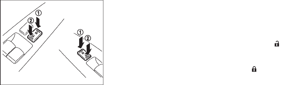
Black plate (140,1)
Model "Z51-D" EDITED: 2009/ 8/ 3
SPA2300
LOCKING WITH POWER DOOR LOCK
SWITCH
Operating the power door lock switch will lock
or unlock all the doors. The switches are located
on the driver’s and front passenger’s door
armrests.
To lock the doors, push the power door lock
switch to the lock position *
1with the driver’s
or front passenger’s door open, then close the
door.
When locking the door this way, be certain
not to leave the Intelligent Key inside the
vehicle.
To unlock the doors, push the power door lock
switch to the unlock position *
2.
Lockout protection
When the power door lock switch (driver or front
passenger) is moved to the lock position with
the Intelligent Key in the port and any door open,
all doors will lock and unlock automatically. With
the Intelligent Key left in the vehicle (not in the
Intelligent Key port) and any door open, all doors
will unlock automatically and a chime will sound
after the door is closed.
These functions help to prevent the Intelligent
Key from being accidentally locked inside the
vehicle.
AUTOMATIC DOOR LOCKS
.All doors will be locked automatically when
the vehicle speed reaches 15 MPH (24
km/h).
.All doors will be unlocked automatically
when the ignition switch is pushed to the
OFF position.
The automatic lock and unlock functions
can be deactivated or activated indepen-
dently of each other.
To deactivate or activate the automatic lock or
unlock system, perform the following procedure:
1. Close all doors.
2. Pushtheignitionswitchtothe“ON”
position.
3. Do one of the following within 20 seconds of
performing step 2:
.To change AUTO UNLOCK settings:
push and hold the power door lock
switch to the position (UNLOCK)
for more than 5 seconds.
.To change AUTO LOCK settings: push
and hold the power door lock switch to
the position (LOCK) for more than
5 seconds.
4. When activated, the hazard indicator will
flash twice. When deactivated, the hazard
indicator will flash once.
5. The ignition must be placed in the OFF and
ON position again between each setting
change.
3-6 Pre-driving checks and adjustments

Black plate (141,1)
Model "Z51-D" EDITED: 2009/ 8/ 3
SPA2433
CHILD SAFETY REAR DOOR LOCK
The child safety rear door lock helps prevent
doors from being opened accidentally, espe-
cially when small children are in the vehicle.
When the levers are in the lock position
*
1, the rear doors can be opened only
from the outside.
To disengage, move the levers to the unlock
position *
2.
WARNING
.Radio waves could adversely affect
electric medical equipment. Those
who use a pacemaker should con-
tact the electric medical equipment
manufacturer for the possible influ-
ences before use.
.The Intelligent Key transmits radio
waves when the buttons are
pushed. The FAA advises that radio
waves may affect aircraft navigation
and communication systems. Do not
operate the Intelligent Key while on
an airplane. Make sure the buttons
are not operated unintentionally
when the unit is stored for a flight.
The Intelligent Key system can operate all the
door locks using the remote controller function
or pushing the request switch on the vehicle
without taking the key out from a pocket or
purse. The operating environment and/or condi-
tions may affect the Intelligent Key system
operation.
Be sure to read the following before using the
Intelligent Key system.
CAUTION
.Be sure to carry the Intelligent Key
with you when operating the vehi-
cle.
.Never leave the Intelligent Key in
the vehicle when you leave the
vehicle.
The Intelligent Key is always communicating with
the vehicle as it receives radio waves. The
Intelligent Key system transmits weak radio
waves. Environmental conditions may interfere
with the operation of the Intelligent Key system
under the following operating conditions.
.When operating near a location where
strong radio waves are transmitted, such
as a TV tower, power station and broad-
casting station.
.When in possession of wireless equipment,
such as a cellular telephone, transceiver,
and CB radio.
.When the Intelligent Key is in contact with or
covered by metallic materials.
.When any type of radio wave remote control
is used nearby.
.When the Intelligent Key is placed near an
electric appliance such as a personal
INTELLIGENT KEY SYSTEM
Pre-driving checks and adjustments 3-7

Black plate (143,1)
Model "Z51-D" EDITED: 2009/ 8/ 3
SPA1948A
INTELLIGENT KEY OPERATING
RANGE
The Intelligent Key functions can only be used
when the Intelligent Key is within the specified
operating range *
1from the request switch.
When the Intelligent Key battery is discharged or
strong radio waves are present near the operat-
ing location, the Intelligent Key system’s operat-
ing range becomes narrower, and the Intelligent
Key may not function properly.
The operating range *
1is within 31.50 in (80
cm) from each request switch.
If the Intelligent Key is too close to the door
glass, handle or rear bumper the request
switches may not function.
When the Intelligent Key is within the operating
range, it is possible for anyone who does not
carry the Intelligent Key to push the request
switch to lock/unlock the doors. SPA2407
DOOR LOCKS/UNLOCKS PRECAU-
TION
.Do not push the door handle request switch
with the Intelligent Key held in your hand as
illustrated. The close distance to the door
handle will cause the Intelligent Key system
to have difficulty recognizing that the In-
telligent Key is outside the vehicle.
.After locking with the door handle request
switch, verify the doors are securely locked
by testing them.
.To prevent the Intelligent Key from being left
inside the vehicle, make sure you carry the
key with you and then lock the doors.
Pre-driving checks and adjustments 3-9

Black plate (144,1)
Model "Z51-D" EDITED: 2009/ 8/ 3
.Do not pull the door handle before pushing
the door handle request switch. The door
will be unlocked but will not open. Release
the door handle once and pull it again to
open the door.
.The Intelligent Key system (opening/closing
doors with the door handle request switch)
can be set to remain inactive. (See “VEHI-
CLE INFORMATION AND SETTINGS” in
the “4. Monitor, heater, air conditioner,
audio, phone and voice recognition sys-
tems” section.)
SPA2408
INTELLIGENT KEY OPERATION
You can lock or unlock the doors without taking
the key out from your pocket or bag.
SPA2434
SPA2435
3-10 Pre-driving checks and adjustments

Black plate (145,1)
Model "Z51-D" EDITED: 2009/ 8/ 3
When you carry the Intelligent Key with you, you
can lock or unlock all doors by pushing the door
handle request switch *
Aor the lift gate
request switch *
Bwithin the range of opera-
tion.
When you lock or unlock the doors or the lift
gate, the hazard indicator will flash and the horn
(or the outside chime) will sound as a confirma-
tion. For details, see “Setting hazard indicator
and horn mode” later in this section.
Locking doors
1. Move the selector lever to the P (Park)
position, push the ignition switch to the OFF
position and make sure you carry the
Intelligent Key with you.*1
2. Close all the doors.*2
3. Push the door handle request switch *
Aor
lift gate request switch *
Bwhile carrying
the Intelligent Key with you.*3
4. All the doors and the lift gate will lock.
5. The hazard indicator flashes twice and the
outside chime sounds twice.
*1: Doors will lock with the Intelligent Key while
the ignition switch is in the ACC or ON
position.
*2: Doors will not lock with the Intelligent Key
while any door is open.
*3: Doors will not lock by pushing the door
handle request switch with the Intelligent
Key inside the vehicle.
However, when an Intelligent Key is inside
the vehicle, doors can be locked with
another registered Intelligent Key.
Unlocking doors
1. Push the door handle request switch *
Aor
the lift gate request switch *
Bonce while
carrying the Intelligent Key with you.
2. The hazard indicator flashes once and the
outside chime sounds once. The corre-
sponding door or the lift gate will unlock.
3. Push the request switch again within 1
minute.
4. The hazard indicator flashes once and the
outside chime sounds once again. All the
doors and the lift gate will unlock.
All doors will be locked automatically unless one
of the following operations is performed within 1
minute after pushing the request switch while
the doors are locked. If during this 1-minute time
period, the request switch is pushed, all doors
will be locked automatically after another 1
minute.
.Opening any door
.Pushing the ignition switch
Inserting the Intelligent Key into the Intelligent
Key port
Power lift gate open (if so equipped)
1. Carry the Intelligent Key.
2. Push the power lift gate opener switch *
C.
3. The lift gate will unlock and automatically
open.
4. The hazard indicator flashes 4 times and the
outside chime sounds.
To close the lift gate, push the power lift gate
button on the key, or power lift gate switch on
the instrument panel or lower part of the lift gate.
(See “LIFT GATE” in the “3. Pre-driving checks
and adjustments” section.)
Setting hazard indicator and horn mode
This vehicle is set in hazard indicator and horn
mode when you first receive the vehicle.
In hazard indicator and horn mode, when the
LOCK button *
1is pushed, the hazard
indicator flashes twice and the horn chirps once.
When the UNLOCK button *
2is pushed,
the hazard indicator flashes once.
If horns are not necessary, the system can be
switched to the hazard indicator mode.
In hazard indicator mode, when the LOCK
button is pushed, the hazard indicator flashes
Pre-driving checks and adjustments 3-11

Black plate (146,1)
Model "Z51-D" EDITED: 2009/ 8/ 3
twice. When the UNLOCK button is
pushed, neither the hazard indicator nor the
horn operates.
Hazard indicator and horn mode:
DOOR LOCK DOOR UNLOCK
Intelligent Key system
(Using door handle or lift gate request switch)
HAZARD - twice
OUTSIDE CHIME - twice
HAZARD - once
OUTSIDE CHIME - once
Remote keyless entry system
(Using or button) HAZARD - twice
HORN - once
HAZARD - once
HORN - none
Hazard indicator mode:
DOOR LOCK DOOR UNLOCK
Intelligent Key system
(Using door handle or lift gate request switch) HAZARD - twice HAZARD - none
Remote keyless entry system
(Using or button) HAZARD - twice HAZARD - none
3-12 Pre-driving checks and adjustments

Black plate (147,1)
Model "Z51-D" EDITED: 2009/ 8/ 3
Switching procedure:
Push the LOCK *
1and UNLOCK *
2
buttons simultaneously for more than 2 seconds
to switch the mode from one to the other.
When pushing the buttons to set the hazard
indicator mode, the hazard indicator flashes 3
times.
When pushing the buttons to set the hazard
indicator and horn mode, the hazard indicator
flashes once and the horn chirps once.
BATTERY SAVER SYSTEM
When all the following conditions are met for 60
minutes, the battery saver system will cut off the
power supply to prevent battery discharge.
.The ignition switch is in the ACC position,
and
.All doors are closed, and
.The selector lever is in the P (Park) position.
WARNING SIGNALS
To help prevent the vehicle from moving
unexpectedly by erroneous operation of the
Intelligent Key listed on the following chart or
to help prevent the vehicle from being stolen,
chime or beep sounds inside and outside the
vehicle and a warning displays in the dot matrix
liquid crystal display.
When a chime or beep sounds or the warning
displays, be sure to check the vehicle and
Intelligent Key.
See “TROUBLESHOOTING GUIDE” later in
this section and “DOT MATRIX LIQUID CRYS-
TAL DISPLAY” in the “2. Instruments and
controls” section.
Pre-driving checks and adjustments 3-13

Black plate (148,1)
Model "Z51-D" EDITED: 2009/ 8/ 3
TROUBLESHOOTING GUIDE
Symptom Possible cause Action to take
When pushing the ignition switch
to stop the engine
The SHIFT P warning appears on the display
and the inside warning chime sounds con-
tinuously.
The selector lever is not in the P (Park)
position.
Shift the selector lever to the P (Park)
position.
When shifting the selector lever
to the P (Park) position. The inside warning chime sounds continuously. The ignition switch is in the ACC or ON
position.
Push the ignition switch to the OFF posi-
tion.
When opening the driver’s door
to get out of the vehicle The inside warning chime sounds continuously.
The ignition switch is in the ACC
position.
Push the ignition switch to the OFF posi-
tion.
The Intelligent Key is in the Intelligent
Key port.
Remove the Intelligent Key from the Intelli-
gent Key port.
When closing the door after get-
ting out of the vehicle
The NO KEY warning appears on the display,
the outside chime sounds 3 times and the
inside warning chime sounds for a few
seconds.
The ignition switch is in the ACC or ON
position.
Push the ignition switch to the OFF posi-
tion.
The SHIFT P warning appears on the display
and the outside chime sounds continuously.
The ignition switch is in the ACC or OFF
position and the selector lever is not in
the P (Park) position.
Move the selector lever to the P (Park)
position and push the ignition switch to the
OFF position.
When closing the door with the
inside lock knob turned to LOCK
The outside chime sounds for a few seconds
and all the doors unlock. The Intelligent Key is inside the vehicle. Carry the Intelligent Key with you.
When pushing the request switch
or the LOCK button on the
Intelligent Key to lock the door
The outside chime sounds for a few seconds.
The Intelligent Key is inside the vehicle. Carry the Intelligent Key with you.
A door is not closed securely. Close the door securely.
3-14 Pre-driving checks and adjustments
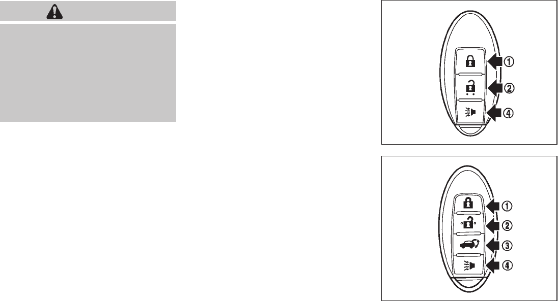
Black plate (149,1)
Model "Z51-D" EDITED: 2009/ 8/ 3
WARNING
The Intelligent Key transmits radio
waves when the buttons are pushed.
The FAA advises that radio waves may
affect aircraft navigation and commu-
nication systems. Do not operate the
Intelligent Key while on an airplane.
Make sure the buttons are not operated
unintentionally when the unit is stored
for a flight.
It is possible to lock/unlock all doors, activate
the panic alarm and open the windows and lift
gate (if so equipped) by pushing the buttons on
the Intelligent Key from outside the vehicle.
Before locking the doors, make sure the
Intelligent Key is not left in the vehicle.
The LOCK/UNLOCK button on the Intelligent
Key can operate at a distance of approximately
33 ft (10 m) from the vehicle. (The effective
distance depends upon the conditions around
the vehicle.)
The lock and unlock buttons will not operate
when:
.the distance between the Intelligent Key and
the vehicle is over 33 ft (10 m).
.the Intelligent Key battery is completely
discharged.
After locking with the remote keyless entry
function, pull the door handle to make sure the
doors are securely locked.
The LOCK/UNLOCK operating range varies
depending on the environment. To securely
operate the lock and unlock buttons, approach
the vehicle to about 3 ft (1 m) from the door.
SPA2252A
Type A
SPA2436
Type B
REMOTE KEYLESS ENTRY SYSTEM
Pre-driving checks and adjustments 3-15

Black plate (150,1)
Model "Z51-D" EDITED: 2009/ 8/ 3
*
1LOCK button
*
2UNLOCK button
*
3Power lift gate button (if so equipped)
*
4PANIC button
HOW TO USE REMOTE KEYLESS
ENTRY SYSTEM
When you lock or unlock the doors or the lift
gate, the hazard indicator will flash and the horn
(or the outside chime) will sound as a confirma-
tion. For details, see “Setting hazard indicator
and horn mode” later in this section.
Locking doors
1. Move the selector lever to the P (Park)
position and push the ignition switch to the
OFF position. Make sure you carry the
Intelligent Key with you.*1
2. Close all the doors and lift gate.*2
3. Push the LOCK button *
1.
4. All the doors and the lift gate will lock.
5. The hazard indicator flashes twice and the
horn chirps once.
*1: Doors will lock while the ignition switch is in
the ACC or ON position.
*2: Doors will not lock while any door is open.
Unlocking doors
1. Push the UNLOCK button *
2once.
2. The hazard indicator flashes once. The
driver’s door will unlock.
3. Push the UNLOCK button again within
1 minute.
4. The hazard indicator flashes once again. All
the doors and the lift gate will unlock.
All doors will be locked automatically unless one
of the following operations is performed within 1
minute after pushing the UNLOCK button while
the doors are locked. If during this 1-minute time
period, the UNLOCK button is pushed, all doors
will be locked automatically after another 1
minute.
.Opening any door
.Pushing the ignition switch
Opening windows
To open the windows, push the door UNLOCK
button *
2for about 3 seconds after the
door is unlocked.
To stop opening, release the UNLOCK
button.
Windows cannot be closed using the button on
the Intelligent Key.
The door windows can be opened or closed by
turning the mechanical key in a door lock. (See
“DOORS” earlier in this section.)
Opening/closing lift gate (if so equipped)
1. Push the power lift gate button *
3
for more than 1 second.
2. The lift gate will automatically open.
The hazard indicator flashes 5 times and the
outside chime sounds for approximately 3
seconds.
To close the lift gate, push the power lift gate
button *
3.
The lift gate will automatically close.
If the button *
3is pushed while the lift
gate is being opened or closed, the lift gate will
reverse.
The power lift gate button *
3cannot be
operated when the ignition switch is in the ON
position.
Using panic alarm
If you are near your vehicle and feel threatened,
you can activate the alarm according to the
following procedure to call attention.
1. Push the PANIC button *
4for more
than 1 second.
3-16 Pre-driving checks and adjustments

Black plate (151,1)
Model "Z51-D" EDITED: 2009/ 8/ 3
2. The theft warning alarm will sound and the
headlights will flash for 25 seconds.
3. The panic alarm stops under either of the
following conditions.
.It has run for 25 seconds, or
.Any of the buttons is pushed. (Note: the
panic button should be pushed for more
than 1 second.)
Setting hazard indicator and horn mode
This vehicle is set in hazard indicator and horn
mode when you first receive the vehicle.
In hazard indicator and horn mode, when the
LOCK button *
1is pushed, the hazard
indicator flashes twice and the horn chirps once.
When the UNLOCK button *
2is pushed,
the hazard indicator flashes once.
If horns are not necessary, the system can be
switched to the hazard indicator mode.
In hazard indicator mode, when the LOCK
button is pushed, the hazard indicator flashes
twice. When the UNLOCK button is
pushed, neither the hazard indicator nor the
horn operates.
Hazard indicator and horn mode:
DOOR LOCK DOOR UNLOCK
Intelligent Key system
(Using door handle or lift gate request switch)
HAZARD - twice
OUTSIDE CHIME - twice
HAZARD - once
OUTSIDE CHIME - once
Remote keyless entry system
(Using or button) HAZARD - twice
HORN - once
HAZARD - once
HORN - none
Hazard indicator mode:
DOOR LOCK DOOR UNLOCK
Intelligent Key system
(Using door handle or lift gate request switch) HAZARD - twice HAZARD - none
Remote keyless entry system
(Using or button) HAZARD - twice HAZARD - none
Pre-driving checks and adjustments 3-17

Black plate (152,1)
Model "Z51-D" EDITED: 2009/ 8/ 3
Switching procedure:
Push the LOCK *
1and UNLOCK *
2
buttons simultaneously for more than 2 seconds
to switch the mode from one to the other.
When pushing the buttons to set the hazard
indicator mode, the hazard indicator flashes 3
times.
When pushing the buttons to set the hazard
indicator and horn mode, the hazard indicator
flashes once and the horn chirps once.
SPA2437
1. Pull the hood lock release handle *
1
located below the instrument panel; the
hood will then spring up slightly.
2. Pull the lever *
2up at the front of the hood
with your fingertips and raise the hood.
3. When closing the hood, slowly close the
hood down and make sure it locks into
place.
WARNING
.Make sure the hood is completely
closed and latched before driving.
Failure to do so could cause the
hood to fly open and result in an
accident.
.If you see steam or smoke coming
from the engine compartment, to
avoid injury do not open the hood.
HOOD
3-18 Pre-driving checks and adjustments

Black plate (153,1)
Model "Z51-D" EDITED: 2009/ 8/ 3
WARNING
.Always be sure the lift gate has
been closed securely to prevent it
from opening while driving.
.Do not drive with the lift gate open.
This could allow dangerous exhaust
gases to be drawn into the vehicle.
See “EXHAUST GAS (carbon mon-
oxide)” in the “5. Starting and driv-
ing” section of this manual.
.Do not leave children unattended
inside the vehicle. They could un-
knowingly activate switches or con-
trols. Unattended children could
become involved in serious acci-
dents.
.Always be sure that hands and feet
are clear of the door frame to avoid
injury while closing the lift gate.
SPA2438
OPERATING MANUAL LIFT GATE
To open the lift gate, unlock it and push the
opener switch *
A. Pull up the lift gate to open.
The lift gate can be unlocked by:
.pushing the unlock button on the
Intelligent Key twice.
.pushing the lift gate request switch (if so
equipped).
.pushing the door handle request switch
twice (if so equipped).
.pushing the power door lock switch to the
unlock position.
.inserting the mechanical key into the driver’s
door key cylinder and turning it to the rear of
the vehicle twice.
To close the lift gate, pull down until it securely
locks.
OPERATING POWER LIFT GATE (if so
equipped)
To operate the power lift gate, the selector lever
must be in the P (Park) position.
The power lift gate will not operate if the battery
voltage is low.
LIFT GATE
Pre-driving checks and adjustments 3-19

Black plate (154,1)
Model "Z51-D" EDITED: 2009/ 8/ 3
SPA2461
Power lift gate main switch
The power lift gate operation can be turned on
or off by the power lift gate main switch on the
instrument panel.
When the power lift gate main switch is pushed
to the “OFF” position, the power operation is not
available by the power lift gate switch on the lift
gate and lift gate opener switch.
SPA2439
SPA2462
SPA2463
SPA2440
3-20 Pre-driving checks and adjustments

Black plate (155,1)
Model "Z51-D" EDITED: 2009/ 8/ 3
Power open
When the lift gate is fully closed, the lift gate will
fully open automatically by:
.pushing the power lift gate switch *
Aon
the instrument panel
.pushing the lift gate opener switch *
B
.pushing the power lift gate button *
Con
the Intelligent Key for more than 1 second
The hazard flashes 4 times and the outside
chime sounds when the lift gate starts opening.
NOTE:
The lift gate can be opened by the power
lift gate switch *
Aor the lift gate button
*
Ceven if the lift gate is locked.
The lift gate will individually unlock and
open. Once the lift gate is closed, its lock
will align to the vehicle’s lock or unlock
status.
Power close
When the lift gate is fully opened, the lift gate
will fully close automatically by:
.pushing the power lift gate switch *
Aon
the instrument panel
.pushing the power lift gate switch *
Don
the lower part of the lift gate
.pushing the lift gate release button *
Con
the Intelligent Key for more than 1 second
The hazard flashes 4 times and the outside
chime sounds when the lift gate starts closing.
Reverse function
The power lift gate will reverse immediately if
one of the following actions is performed during
power open or power close.
.pushing the power lift gate switch *
Aon
the instrument panel
.pushing the lift gate switch *
Don the lower
part of the lift gate
.pushing the lift gate button *
Con
the Intelligent Key.
The outside chime sounds when the lift gate
starts to reverse.
The power lift gate button *
Con the
Intelligent Key cannot be operated when the
ignition switch is in the ON position.
Auto reverse function
The auto-reverse function enables the lift gate to
automatically reverse when something is caught
in the lift gate as it is opening or closing. When
the control unit detects an obstacle, the lift gate
will reverse and return to the full open or full
close position.
If a second obstacle is detected, the lift gate
motion will stop and the drive motor will
disengage. The lift gate will enter the manual
mode.
A pinch sensor is mounted on each side of the
lift gate. If an obstacle is detected by the pinch
sensor during power close, the lift gate will
reverse and return to the full open position
immediately.
NOTE:
If the pinch sensor is damaged or removed,
the power close function will not operate.
WARNING
There is a small distance immediately
before the closed position that cannot
be detected. Make sure that all passen-
gers keep their hands, etc., clear from
the lift gate opening before closing the
lift gate.
Manual mode
If power operation is not available, the lift gate
can be operated manually. Power operation may
not be available if multiple obstacles have been
detected in a single power cycle or if the battery
voltage is low. When the power lift gate main
switch is in the OFF position, the lift gate can be
opened manually by pushing the lift gate opener
switch. If the power lift gate opener switch is
Pre-driving checks and adjustments 3-21

Black plate (156,1)
Model "Z51-D" EDITED: 2009/ 8/ 3
pushed during power open or close, the power
operation will be canceled and the lift gate can
be operated manually.
SPA2464
Safe Mode
If the gas stays of the lift gate *
1lose pressure,
the power lift gate safe mode is activated. When
thesafemodeisactivated,theliftgate
intermittently closes. Then the lift gate will be
pulled to the closed and latched position by a
motor.
The power lift gate cannot be opened using the
switches at any time in the safe mode.
Do not operate the lift gate again until it is
checked by a NISSAN dealer.
CAUTION
.If the power lift gate does not stay
open or if the lift gate unexpectedly
closes at any time, do not operate
the lift gate. There may be a pres-
sure loss in one or both of the lift
gate gas stays. Have the lift gate
inspected by a NISSAN dealer.
.Do not activate the power lift gate if
one or both of the lift gate gas stays
are removed. Damage to the lift
gate or power lift gate mechanisms
may occur.
AUTO CLOSURE
If the lift gate is pulled down to a partly open
position, the lift gate will pull itself to the closed
position.
Do not apply excessive force when the
auto closure is operating. Excessive force
applied may cause the mechanism to
malfunction.
CAUTION
.The lift gate will automatically close
from a partly open position. To avoid
3-22 Pre-driving checks and adjustments

Black plate (157,1)
Model "Z51-D" EDITED: 2009/ 8/ 3
pinching, keep hands and fingers
away from lift gate opening.
.Do not let children operate the lift
gate.
SPA1915
LIFT GATE RELEASE
If the lift gate cannot be opened due to a
discharged battery, follow these steps.
1. Remove the cover inside of the lift gate with
a suitable tool.
2. Move the lever toward the direction *
Aas
illustrated to open the lift gate.
Have the vehicle checked by a NISSAN dealer.
SPA2441
OPENING FUEL-FILLER DOOR
To open the fuel-filler door, push the opener
switch located below the instrument panel. To
lock, close the fuel-filler door securely.
FUEL-FILLER DOOR
Pre-driving checks and adjustments 3-23

Black plate (158,1)
Model "Z51-D" EDITED: 2009/ 8/ 3
FUEL-FILLER CAP
WARNING
.Gasoline is extremely flammable
and highly explosive under certain
conditions. You could be burned or
seriously injured if it is misused or
mishandled. Always stop engine
and do not smoke or allow open
flames or sparks near the vehicle
when refueling.
.Do not attempt to top off the fuel
tank after the fuel pump nozzle
shuts off automatically. Continued
refueling may cause fuel overflow,
resulting in fuel spray and possibly
a fire.
.Use only an original equipment type
fuel-filler cap as a replacement. It
has a built-in safety valve needed
for proper operation of the fuel
system and emission control sys-
tem. An incorrect cap can result in a
serious malfunction and possible
injury. It could also cause the mal-
function indicator light to come on.
.Never pour fuel into the throttle
body to attempt to start your vehi-
cle.
.Do not fill a portable fuel container
in the vehicle or trailer. Static elec-
tricity can cause an explosion of
flammable liquid, vapor or gas in
any vehicle or trailer. To reduce the
risk of serious injury or death when
filling portable fuel containers:
— Always place the container on
the ground when filling.
— Do not use electronic devices
when filling.
— Keep the pump nozzle in contact
with the container while you are
filling it.
— Use only approved portable fuel
containers for flammable liquid.
CAUTION
.If fuel is spilled on the vehicle body,
flush it away with water to avoid
paint damage.
.Insert the cap straight into the fuel-
filler tube, then tighten until the
fuel-filler cap clicks. Failure to tight-
en the fuel-filler cap properly may
cause the malfunction indicator
light (MIL) to illuminate. If the
light illuminates because the fuel-
filler cap is loose or missing, tighten
or install the cap and continue to
drive the vehicle. The light
should turn off after a few driving
trips. If the light does not turn
off after a few driving trips, have the
vehicle inspected by a NISSAN deal-
er.
3-24 Pre-driving checks and adjustments

Black plate (159,1)
Model "Z51-D" EDITED: 2009/ 8/ 3
SPA2442
The fuel-filler cap is a ratcheting type. Turn the
cap counterclockwise to remove. To tighten, turn
the cap clockwise until ratcheting clicks are
heard.
Put the fuel-filler cap on the cap holder *
A
while refueling.
WARNING
.Do not adjust the steering wheel
while driving. You could lose control
of your vehicle and cause an acci-
dent.
.Do not adjust the steering wheel
any closer to you than is necessary
for proper steering operation and
comfort. The driver’s air bag inflates
with great force. If you are unrest-
rained, leaning forward, sitting side-
ways or out of position in any way,
you are at greater risk of injury or
death in a crash. You may also
receive serious or fatal injuries from
the air bag if you are up against it
when it inflates. Always sit back
against the seatback and as far
away as practical from the steering
wheel. Always use the seat belts.
SPA2443
MANUAL OPERATION
Tilt or telescopic operation
Pull the lock lever *
1down and adjust the
steering wheel forward or rearward to the
desired position.
Push the lock lever up securely to lock the
steering wheel in place.
Pull the lock lever *
2and adjust the steering
wheel up or down to the desired position.
Release the lock lever to lock the steering wheel
in place.
TILT/TELESCOPIC STEERING
Pre-driving checks and adjustments 3-25
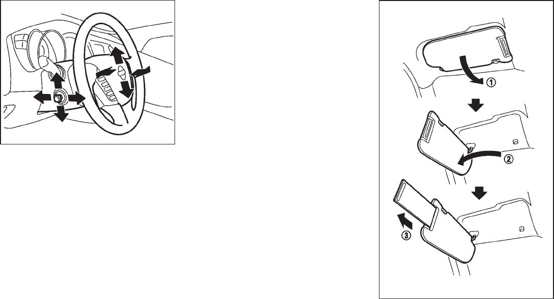
Black plate (160,1)
Model "Z51-D" EDITED: 2009/ 8/ 3
SPA2444A
ELECTRIC OPERATION
Tilt or telescopic operation
Move the lever to adjust the steering wheel up or
down, forward or rearward to the desired
position.
Entry/Exit function operation (if so
equipped):
The automatic drive positioner system will make
the steering wheel move up automatically when
the driver’s door is opened with the ignition
switch in the LOCK position. This lets the driver
get into and out of the seat more easily.
For more information, see “AUTOMATIC DRIVE
POSITIONER” later in this section.
SIC3451
SUN VISORS
3-26 Pre-driving checks and adjustments

Black plate (161,1)
Model "Z51-D" EDITED: 2009/ 8/ 3
CAUTION
.Do not store the main sun visor
before storing the extension sun
visor.
.Do not pull the extension sun visor
forcedly downward.
1. To block out glare from the front, swing
down the main sun visor *
1.
2. To block glare from the side, remove the
main sun visor from the center mount and
swing it to the side *
2.
3. Draw out the extension sun visor *
3from
the main sun visor to block from further
glare.
SPA2447
INSIDE MIRROR
Adjust the height and the angle of the inside
mirror to the desired position.
SPA2143
Manual anti-glare type
The night position *
1will reduce glare from the
headlights of vehicles behind you at night.
Use the day position *
2when driving in daylight
hours.
WARNING
Use the night position only when ne-
cessary, because it reduces rear view
clarity.
MIRRORS
Pre-driving checks and adjustments 3-27

Black plate (162,1)
Model "Z51-D" EDITED: 2009/ 8/ 3
SPA2422A
Type A
SPA2450
Type B
Automatic anti-glare type
The inside mirror is designed so that it
automatically changes reflection according to
the intensity of the headlights of the following
vehicle.
The anti-glare system will be automatically
turned on when the ignition switch is pushed
to the ON position.
When the anti-glare system is turned on, the
indicator light *
Awill illuminate and excessive
glare from the headlights of the vehicle behind
you will be reduced.
Type A: Push the switch *
Bto make the
inside rearview mirror operate normally and the
indicator light will turn off. Push the switch
again to turn the system on.
Type B: Push the “*” switch *
Cto make the
inside rearview mirror operate normally. The
indicator light will turn off. Push the “I” switch
*
Dto turn the system on.
Do not allow any object to cover the
sensors *
Eor apply glass cleaner on
them. Doing so will reduce the sensitivity
of the sensor, resulting in improper opera-
tion.
For the compass (if so equipped) operation, see
“COMPASS” in the “2. Instruments and con-
trols” section.
For the HomeLink®Universal Transceiver opera-
tion, see “HomeLink®UNIVERSAL TRANSCEI-
VER” in the “2. Instruments and controls”
section.
3-28 Pre-driving checks and adjustments

Black plate (163,1)
Model "Z51-D" EDITED: 2009/ 8/ 3
SPA2319
OUTSIDE MIRRORS
WARNING
Objects viewed in the outside mirror on
the passenger side are closer than they
appear. Be careful when moving to the
right. Using only this mirror could cause
an accident. Use the inside mirror or
glance over your shoulder to properly
judge distances to other objects.
Adjusting outside mirrors
The outside mirror control switch is located on
the armrest.
The outside mirror will operate only when the
ignition switch is in the ACC or ON position.
Turn the switch right or left to select the right or
left side mirror *
1, then adjust using the control
switch *
2.
Defrosting outside mirrors (if so
equipped)
The outside mirrors will be heated when the rear
window defroster switch is operated.
SPA1829
Foldable outside mirrors
Fold the outside mirror by pushing it toward the
rear of the vehicle.
Pre-driving checks and adjustments 3-29

Black plate (164,1)
Model "Z51-D" EDITED: 2009/ 8/ 3
SIC2064
VANITY MIRROR
To use the front vanity mirror, pull down the sun
visor and pull up the cover.
The automatic drive positioner system has two
features:
.Entry/exit function
.Memory storage
ENTRY/EXIT FUNCTION
This system is designed so that the driver’s seat
and steering column will automatically move
when the selector lever is in the P (Park)
position. This allows the driver to get into and
out of the driver’s seat more easily.
The driver’s seat will slide backward and the
steering wheel will move up when the driver’s
door is opened with the ignition switch in the
LOCK position and the Intelligent Key not
inserted in the Intelligent Key port.
The driver’s seat and steering wheel will return
to the previous positions when the ignition
switch is pushed to the ACC position.
The driver’s seat will not return to the previous
positions if the seat or steering adjusting switch
is operated when the seat is at the exit position.
Cancel or activate entry/exit function
The selector lever must be in the P (Park)
position with the ignition switch in the OFF
position.
The entry/exit function can be activated or
canceled by pressing and holding the SET
switch for more than 10 seconds.
The indicator lights on the memory switches (1
and 2) will blink once when the function is
canceled, and the indicator lights will blink twice
when the function is activated. Note that the
indicator lights may illuminate after 5 seconds
while holding the SET switch. This indicates
readiness for linking the Intelligent Key to a
stored memory position. Keep the SET switch
pressed for more than 10 seconds to turn on or
off the entry/exit function.
The entry/exit function can also be activated or
canceled if the “Lift Steering Wheel on Exit” key
or “Slide Driver Seat Back on Exit” key is turned
to ON or OFF in the “Comfort & Conv.” settings.
(See “VEHICLE INFORMATION AND SET-
TINGS” in the “4. Monitor, heater, air condi-
tioner, audio, phone and voice recognition
systems” section.)
Initialize entry/exit function
If the battery cable is disconnected, or if the fuse
opens, the entry/exit function will not work
though this function was set on before. In such
a case, after connecting the battery or replacing
with a new fuse, open and close the driver’s
door more than two times after the ignition
switch is turned from the ON position to the
LOCK position. The entry/exit function will be
activated.
AUTOMATIC DRIVE POSITIONER (if
so equipped)
3-30 Pre-driving checks and adjustments

Black plate (165,1)
Model "Z51-D" EDITED: 2009/ 8/ 3
SPA2445
MEMORY STORAGE
Two positions for the driver’s seat, steering
column and outside mirrors can be stored in the
automatic drive positioner memory. Follow these
procedures to use the memory system.
1. Move the selector lever to the P (Park)
position.
2. Push the ignition switch to the ON position.
3. Adjust the driver’s seat, steering column and
outside mirrors to the desired positions by
manually operating each adjusting switch.
For additional information, see “SEATS” in
the “1. Safety — Seats, seat belts and
supplemental restraint system” section and
“TILT/TELESCOPIC STEERING” earlier in
this section and “OUTSIDE MIRRORS”
earlier in this section.
4. Push the SET switch and, within 5 seconds,
push the memory switch (1 or 2).
The indicator light for the pushed memory
switch will stay on for approximately 5
seconds after pushing the switch.
If memory is stored in the same memory
switch, the previous memory will be deleted.
Linking Intelligent Key to a stored mem-
ory position
The Intelligent Key can be linked to a stored
memory position with the following procedure.
1. Follow one of the steps for storing a memory
position.
.While the indicator light for the memory
switch being set is illuminated for 5 sec-
onds, push the button on the Intelligent
Key.
.Push the ignition switch to the OFF position,
and then push the SET switch. Push the
button while pushing the memory
button while the indicator light stays on for
approximately 5 seconds.
If the indicator light blinks, the Intelligent Key is
linked to that memory setting.
Push the ignition switch to the OFF position, and
then push the button on the Intelligent Key.
The driver’s seat, steering wheel and outside
mirrors will move to the memorized position.
Confirming memory storage
.Push the ignition switch to the ON position
and push the SET switch. If the main
memory has not been stored, the indicator
light will come on for approximately 0.5
second. When the memory has stored in
position, the indicator light will stay on for
approximately 5 seconds.
.If the battery cable is disconnected, or if the
fuse opens, the memory will be canceled. In
this case, reset the desired position using
the previous procedure.
.If optional keys are added to your vehicle,
the memory storage procedure to switch 1
or 2 and linking Intelligent Key procedure to
a stored memory position should be per-
formed again for each Intelligent Key. For
additional Intelligent Key information, see
“KEYS” earlier in this section.
Selecting the memorized position
1. Move the selector lever to the P (Park)
position.
2. Use one of the following methods to move
the driver’s seat, the outside mirrors and the
steering wheel.
Pre-driving checks and adjustments 3-31
Black plate (166,1)
Model "Z51-D" EDITED: 2009/ 8/ 3
.Push the ignition switch to the ON
position and push the memory switch
(1 or 2).
.Within 45 seconds of opening the
driver’s door, push the memory switch
(1 or 2).
The driver’s seat, steering column and
outside mirrors will move to the memorized
position with the indicator light flashing, and
then the light will stay on for approximately 5
seconds.
SYSTEM OPERATION
The automatic drive positioner system will not
work or will stop operating under the following
conditions:
.When the vehicle speed is above 4 MPH (7
km/h) (entry/exit function).
.When the vehicle is driven (memory sto-
rage).
.When the adjusting switch for the driver’s
seat and steering column is turned on while
the automatic drive positioner is operating.
.When the seat, steering column and outside
mirrors have already been moved to the
memorized position.
.When no position is stored in the memory
switch.
.When the engine is started while moving the
automatic drive positioner.
.When the selector lever is moved from the P
(Park) position to any other position. (How-
ever, it will not be canceled while the seat
and steering column are returning to the
previous positions (entry/exit function).)
.When the driver’s door remains open for
more than 45 seconds and the ignition
switch is not in the ON position.
3-32 Pre-driving checks and adjustments
Black plate (167,1)
Model "Z51-D" EDITED: 2009/ 8/ 3
MEMO
Pre-driving checks and adjustments 3-33

Black plate (13,1)
4 Monitor, heater, air conditioner, audio,
phone and voice recognition systems
Model "Z51-D" EDITED: 2009/ 8/ 3
Safety note ....................................................... 4-2
Center multi-function control panel
(models with color display screen) ......................... 4-2
How to use multi-function controller ................... 4-4
How to use touch screen
(models with navigation system) ........................ 4-4
Start-up screen (models with navigation system) ... 4-6
Start menu (models with navigation system) ......... 4-6
How to select menus on the screen ................... 4-7
Vehicle information and settings............................. 4-8
How to use STATUS button.............................. 4-8
How to use brightness control and display ON/
OFF button................................................... 4-8
How to use INFO button.................................. 4-8
How to use SETTING button .......................... 4-12
Rearview monitor (if so equipped) ........................ 4-19
How to read the displayed lines....................... 4-20
How to park with predicted course lines............ 4-20
Difference between predicted and actual
distances ................................................... 4-22
How to adjust the screen............................... 4-24
Operating tips ............................................. 4-24
Ventilators ...................................................... 4-25
Heater and air conditioner .................................. 4-26
Automatic operation...................................... 4-28
Manual operation ......................................... 4-29
To turn the system ON/OFF ........................... 4-30
Operating tips ............................................. 4-30
In-cabin microfilter........................................ 4-30
Servicing air conditioner ................................ 4-30
Audio system .................................................. 4-31
Audio operation precautions ........................... 4-31
FM-AM radio with Compact Disc (CD)
changer ..................................................... 4-39
FM-AM-SAT radio with Compact Disc (CD)
changer ..................................................... 4-44
CompactFlash (CF) player operation
(models with navigation system) ...................... 4-49
iPod®player operation (if so equipped).............. 4-51
“MUSIC BOX” hard-disk drive
(models with navigation system) ...................... 4-52
CD/CF (CompactFlash) care and cleaning ......... 4-59
Steering-wheel-mounted controls for audio ........ 4-61
Antenna ..................................................... 4-62
NISSAN Mobile Entertainment System (MES)
(if so equipped) ............................................... 4-63
DVD player operation precautions .................... 4-63
Digital Versatile Disc (DVD) system
components................................................ 4-64
Remote controller and headphones battery
replacement................................................ 4-68
Before operating the DVD entertainment
system....................................................... 4-68
Playing a Digital Versatile Disc (DVD) ............... 4-69

Black plate (14,1)
Model "Z51-D" EDITED: 2009/ 8/ 3
Care and maintenance .................................. 4-73
Car phone or CB radio...................................... 4-74
Bluetooth®Hands-Free Phone System with
navigation system............................................. 4-75
Regulatory information ................................... 4-76
Voice commands.......................................... 4-76
Control buttons ........................................... 4-77
Pairing procedure......................................... 4-77
Phonebook registration .................................. 4-78
Making a call............................................... 4-80
Receiving a call ........................................... 4-81
During a call ............................................... 4-81
Phone setting.............................................. 4-82
Troubleshooting guide ................................... 4-84
Bluetooth®Hands-Free Phone System without
navigation system (if so equipped) ....................... 4-85
Regulatory information ................................... 4-86
Initialization ................................................. 4-86
Operating tips ............................................. 4-86
Giving voice commands................................. 4-86
Control buttons ........................................... 4-88
Getting started ............................................ 4-88
Choosing a language .................................... 4-88
Pairing procedure......................................... 4-88
Making a call by entering a phone number ......... 4-89
Receiving a call ........................................... 4-89
List of voice commands ................................. 4-90
Call........................................................... 4-90
Phone book ................................................ 4-92
Memo pad.................................................. 4-94
Setup........................................................ 4-94
Speaker Adaptation (SA) mode ....................... 4-96
Troubleshooting guide ................................... 4-98
NISSAN Voice Recognition System
(models with navigation system) .......................... 4-99
NISSAN voice recognition standard mode.......... 4-99
Using the system ....................................... 4-102
NISSAN voice recognition alternate command
mode ...................................................... 4-109
Using the system ....................................... 4-115
Troubleshooting guide ................................. 4-121
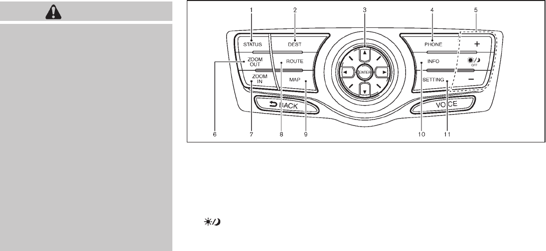
Black plate (170,1)
Model "Z51-D" EDITED: 2009/ 8/ 3
WARNING
.Do not disassemble or modify this
system. If you do, it may result in
accidents, fire, or electric shock.
.Do not use this system if you notice
any abnormality, such as a frozen
screen or lack of sound. Continued
use of the system may result in
accident, fire or electric shock.
.In case you notice any foreign
object in the system hardware, spill
liquid on it, or notice smoke or smell
coming from it, stop using the
system immediately and contact
your nearest NISSAN dealer. Ignor-
ing such conditions may lead to
accidents, fire, or electric shock.
.Park the vehicle in a safe location
and apply the parking brake to view
the images on the front center dis-
play screen using devices connected
to the auxiliary input jacks.
Do not attempt to operate the system in
extreme temperature conditions [below
−48F(−208C) and above 1588F(708C)].
Operating this system under these condi-
tions may result in system malfunctions.
SAA1845
With navigation system
1. “STATUS” status display button (P.4-8)
2, 6, 7, 8, 9.
For navigation system control buttons (Refer to the
separate Navigation System Owner’s Manual.)
3. Multi-function controller (P.4-4)
4. “PHONE” Bluetooth®Hands-Free Phone Sys-
tem button (P.4-75)
5. “ OFF” brightness control and display ON/
OFF button (P.4-8)
10. “INFO” vehicle and navigation information button
(P.4-8)
11. “SETTING” button (P.4-12)
SAFETY NOTE
CENTER MULTI-FUNCTION
CONTROL PANEL (models with
color display screen)
4-2 Monitor, heater, air conditioner, audio, phone and voice recognition systems

Black plate (171,1)
Model "Z51-D" EDITED: 2009/ 8/ 3
SAA1846
Without navigation system
1. “INFO” vehicle information button (P.4-8)
2. “STATUS” status display button (P.4-8)
3. Multi-function controller (P.4-4)
4. “ OFF” brightness control and display ON/
OFF button (P.4-8)
5. “SETTING” button (P.4-12)
When you use this system, make sure the
engine is running.
If you use the system with the engine not
running (ignition ON or ACC) for a long
time, it will use up all the battery power,
and the engine will not start.
SAA1847
With navigation system
SAA1848
Without navigation system
Monitor, heater, air conditioner, audio, phone and voice recognition systems 4-3
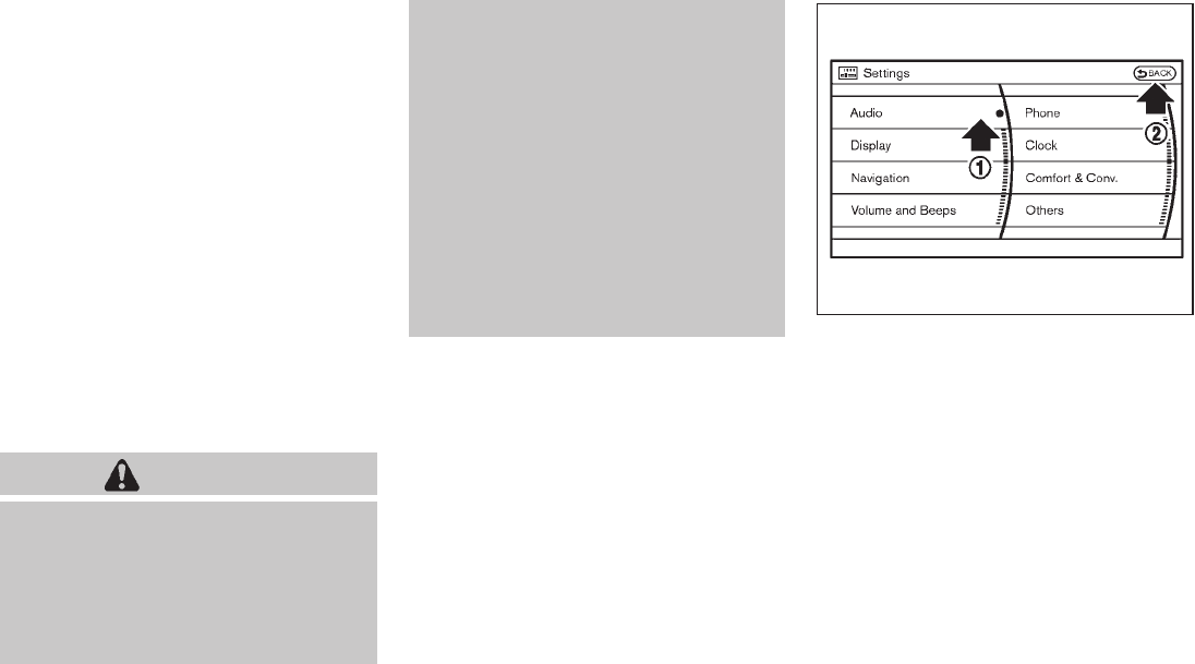
Black plate (172,1)
Model "Z51-D" EDITED: 2009/ 8/ 3
HOW TO USE MULTI-FUNCTION
CONTROLLER
Choose an item on the display using the main
directional buttons *
2(or additional directional
buttons *
6with navigation system) or center
dial *
3, and push the ENTER button *
1for
operation.
If you push the BACK button *
4before the
setup is completed, the setup will be canceled
and/or the display will return to the previous
screen. This button can also be used to delete
characters that have been input.
After the setup is completed, push the BACK
button *
4and return to the previous screen.
For the VOICE button *
5functions, refer to the
separate Navigation System Owner’s Manual.
HOW TO USE TOUCH SCREEN
(models with navigation system)
CAUTION
.The glass screen on the liquid
crystal display may break if it is hit
with a hard or sharp object. If the
glass breaks, do not touch the liquid
crystalline material, which contains
a small amount of mercury. In case
of contact with skin, wash immedi-
ately with soap and water.
.To clean the display, use a soft, dry
cloth. If additional cleaning is ne-
cessary, use a small amount of
neutral detergent with a soft cloth.
Never use a rough cloth, alcohol,
benzine, thinner or any kind of
solvent or paper towel with a che-
mical cleaning agent. They will
scratch or deteriorate the panel.
.Do not splash any liquid such as
water or car fragrance on the dis-
play. Contact with liquid will cause
the system to malfunction.
To ensure safe driving, some functions cannot
be operated while driving.
The on-screen functions that are not available
while driving will be “grayed out” or muted.
Park the vehicle in a safe location and then
operate the navigation system.
SAA1542
Touch screen operation
With this system, the same operations as those
for the multi-function controller are possible
using the touch screen operation.
Selecting the item:
Touch an item to select. When you select the
“Audio” settings, touch the “Audio” area *
1on
the screen.
Touch the BACK *
2button to return the
previous screen.
4-4 Monitor, heater, air conditioner, audio, phone and voice recognition systems

Black plate (173,1)
Model "Z51-D" EDITED: 2009/ 8/ 3
SAA1543
Adjusting the item:
Touch the + *
1or −*
2button to adjust the
settings.
Touch the UP *
3or DOWN *
4button to
move to the previous or next page.
SAA1617
Inputting characters:
Touch the letter or number *
1.
There are some options available when inputting
characters.
.Uppercase:
Shows uppercase characters.
.Lowercase:
Shows lowercase characters.
.Symbols:
Shows symbols such as the question mark
(?).
.Space:
Inserts a space.
.Delete:
Deletes the last character that has been
input with one touch. Push and hold the
button to delete all of the characters.
.OK:
Completes character inputs.
Touch screen maintenance
If you clean the display screen, use a dry, soft
cloth. If additional cleaning is necessary, use a
small amount of neutral detergent with a soft
cloth. Never spray the screen with water or
detergent. Dampen the cloth first, and then wipe
the screen.
Monitor, heater, air conditioner, audio, phone and voice recognition systems 4-5
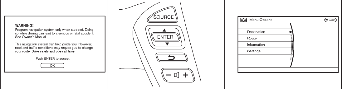
Black plate (174,1)
Model "Z51-D" EDITED: 2009/ 8/ 3
SAA1454
START-UP SCREEN (models with navi-
gation system)
When you push the ignition switch to the ACC
or ON position, the SYSTEM START-UP warn-
ing is displayed on the screen. When you read
and agree with the warning, push the ENTER
button.
If you do not push the ENTER button, you will
not be able to use the NAVI system.
To proceed to the NAVI system, refer to the
separate Navigation System Owner’s Manual.
SAA1860
START MENU (models with navigation
system)
The start menu can be displayed using the
ENTER switch on the steering-wheel-mounted
controls.
1. While the map (if so equipped) or status
screen is displayed, push and hold the
ENTER switch until the “Menu Options”
screen appears.
2. Highlight the preferred item tilting the
ENTER switch up or down, and then push
the ENTER switch.
SAA1591
Available items
Destination/Route:
These items are for the navigation system. If your
vehicle is equipped with the navigation system,
see the separate Navigation System Owner’s
Manual for details.
Information:
Displays the information screen. It is the same
screen that appears when you push the INFO
button.
Settings:
Displays the settings screen. It is the same
screen that appears when you push the SET-
4-6 Monitor, heater, air conditioner, audio, phone and voice recognition systems

Black plate (175,1)
Model "Z51-D" EDITED: 2009/ 8/ 3
TING button.
SAA1510
HOW TO SELECT MENUS ON THE
SCREEN
Vehicle functions are viewed on the display
screen in menus. Whenever a menu selection is
made or menu item is highlighted, different areas
onthescreenprovideyouwithimportant
information. See the following for details.
1. Header:
Shows the path used to get to the current
screen. (i.e. push SETTING button >
choose “Comfort & Conv.” menu item.)
2. Menu Selections:
Shows the options to choose within that
menu screen. (i.e. Auto Interior Illumination,
etc.)
3. UP/DOWN Movement indicator:
Shows that the multi-function controller may
be used to move UP/DOWN on the screen
and select more options.
4. Screen Count:
Shows the number of menu selections
available for that screen (i.e. 1/9).
5. Footer/Information Line:
Provides more information (if available)
about the menu selection currently high-
lighted. (i.e. Cabin lighting when unlock-
ing doors.)
Monitor, heater, air conditioner, audio, phone and voice recognition systems 4-7

Black plate (176,1)
Model "Z51-D" EDITED: 2009/ 8/ 3
HOW TO USE STATUS BUTTON
To display the status of the audio, climate control
system, fuel consumption and navigation system
(if so equipped), push the STATUS button. The
following information will appear when the
STATUS button is pushed.
Audio ?Audio and Climate control system ?
Audio and fuel consumption ?Audio and
Navigation system (if so equipped) ?Audio
HOW TO USE BRIGHTNESS CON-
TROL AND DISPLAY ON/OFF BUTTON
Push the “ OFF” button to switch the
display brightness to the daytime mode or the
nighttime mode, and to adjust the display
brightness using the multi-function controller
while the indicator is displayed at the bottom of
the screen.
The display brightness can also be adjusted
using the brightness UP button (+) or bright-
ness DOWN button (−).
Push and hold the “ OFF” button for more
than 2 seconds to turn the display off. Push the
button again to turn the display on.
HOW TO USE INFO BUTTON
The display screen shows vehicle and navigation
(if so equipped) information for your conveni-
ence.
The information shown on the screen should be
a guide to determine the condition of the vehicle.
See the following for details.
SAA1545
With navigation system
SAA1511
Without navigation system
VEHICLE INFORMATION AND
SETTINGS
4-8 Monitor, heater, air conditioner, audio, phone and voice recognition systems

Black plate (177,1)
Model "Z51-D" EDITED: 2009/ 8/ 3
Vehicle information display
1. Push the INFO button on the control panel.
The screens as illustrated will appear.
2. Choose an item using the multi-function
controller and push the ENTER button.
3. After viewing or adjusting the information on
the following screens, push the BACK
button to return to the INFORMATION
menu.
For the items “Traffic Info.”, “Where am I?”,
“GPS Satellite Info.” and “Navigation Version”,
refer to the separate Navigation System Own-
er’s Manual. SAA1546
SAA1547
Fuel Economy information
The distance to empty, average fuel economy
and current fuel economy (shown on the right
side bar) will be displayed for reference.
To reset the Average Fuel Economy, use the
multi-function controller to highlight the “Reset”
key and push the ENTER button.
If the “View” key is highlighted with the multi-
function controller and the ENTER button is
pushed, the average fuel consumption history
will be displayed in graph form along with the
average for the previous Reset-to-Reset period.
The unit can be converted between “US” and
“Metric”. (See “HOW TO USE SETTING
BUTTON” later in this section.)
The fuel economy information may differ from the
information displayed on the dot matrix liquid
crystal display. This is due to the timing
difference in updating the information and does
not indicate a malfunction.
Monitor, heater, air conditioner, audio, phone and voice recognition systems 4-9

Black plate (178,1)
Model "Z51-D" EDITED: 2009/ 8/ 3
SAA1554
Maintenance information
To set the maintenance interval for Reminders 1
to 4, choose an item using the multi-function
controller and push the ENTER button.
You can also set to display a message to remind
you that the maintenance needs to be per-
formed.
The following example shows how to set
Reminder 1. Use the same steps to set the
other maintenance information.
SAA1555
1. Reset the driving distance to the new
maintenance schedule.
2. Set the interval (mileage) of the maintenance
schedule. To determine the recommended
maintenance interval, refer to your “NISSAN
Service and Maintenance Guide”.
3. To display the reminder automatically when
the set trip distance is reached, highlight the
“Interval Reminder” key with the multi-
function controller and push the ENTER
button.
4. To return the display to MAINTENANCE
INFO., push the BACK button.
Maintenance information display cannot be
operated when the vehicle is moving. Stop the
vehicle in a safe place to see the information.
The unit can be converted between “US” and
“Metric”. (See “HOW TO USE SETTING
BUTTON” later in this section.)
4-10 Monitor, heater, air conditioner, audio, phone and voice recognition systems

Black plate (179,1)
Model "Z51-D" EDITED: 2009/ 8/ 3
SAA1611
The Reminder will be automatically displayed as
shown when both of the following conditions are
met:
.the vehicle is driven the set distance and the
ignition switch is pushed to the LOCK
position.
.the ignition switch is pushed to the ACC or
ON position the next time you drive the
vehicle after the set value has been reached.
To return to the previous display after the
“MAINTENANCE NOTICE” screen is displayed,
push the BACK button.
The “MAINTENANCE NOTICE” screen is dis-
played each time the ignition switch is pushed to
the ON position until one of the following
conditions is met:
.“Reset Distance” is selected.
.“Interval Reminder” is set to OFF.
.the maintenance interval is set again.
SAA1592
Voice Recognition information (models
with navigation system)
When you use the NISSAN Voice Recognition
system for the first time or if you do not know
how to operate it, you can display the voice
command list or user guide for confirmation.
(See “NISSAN VOICE RECOGNITION SYS-
TEM (models with navigation system)” later in
this section for the details.)
Command List:
Displays a list of voice commands that the
system can recognize.
Monitor, heater, air conditioner, audio, phone and voice recognition systems 4-11
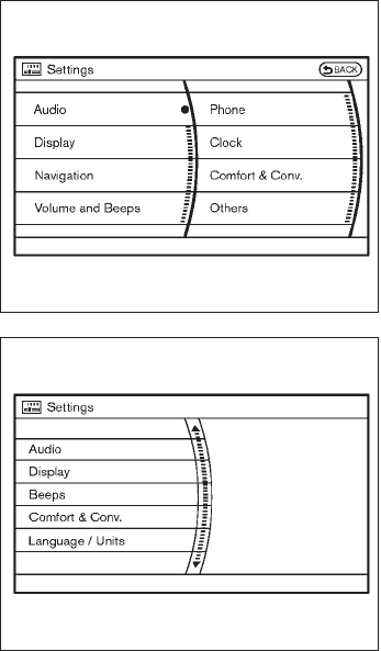
Black plate (180,1)
Model "Z51-D" EDITED: 2009/ 8/ 3
User Guide:
Displays a simplified operation manual of the
voice recognition system and how to use the
voice commands.
SAA1556
With navigation system
SAA1514
Without navigation system
HOW TO USE SETTING BUTTON
The display as illustrated will appear when the
SETTING button is pushed.
For navigation settings, refer to the separate
Navigation System Owner’s Manual.
To show the “Comfort & Conv.” item, push the
ignition switch to the ON position.
4-12 Monitor, heater, air conditioner, audio, phone and voice recognition systems

Black plate (181,1)
Model "Z51-D" EDITED: 2009/ 8/ 3
SAA1557
Audio settings
The above display will appear when pushing the
SETTING button, selecting the “Audio” key
with the multi-function controller and pushing
the ENTER button.
Bass/Treble/Balance/Fade:
To adjust the speaker tone quality and sound
balance, select the “Bass”, “Treble”, “Bal-
ance”or“Fade” key and adjust it with the
multi-function controller.
These items can also be adjusted by pushing
and turning the AUDIO knob.
Speed Sensitive Vol.:
Sound volume is increased according to the
vehicle speed. Choose the effect level from OFF
(0) to 5.
SAA1813
With navigation system
Display settings
The above display will appear when pushing the
SETTING button, selecting “Display” key with
the multi-function controller and pushing the
ENTER button.
Display:
To turn off the screen, push the ENTER button
and turn the “Display” indicator off. The other
method is to push and hold the “ OFF”
button for more than 2 seconds.
When any mode button is pushed with the
screen off, the screen turns on for further
operation. The screen will turn off automatically
5 seconds after the operation is finished.
Monitor, heater, air conditioner, audio, phone and voice recognition systems 4-13

Black plate (182,1)
Model "Z51-D" EDITED: 2009/ 8/ 3
To turn on the screen, set this item to the ON
position, or push the “ OFF” button.
Brightness/Contrast/Background Color:
To adjust the brightness and contrast of the
screen, select the “Brightness”or“Contrast”
key and push the ENTER button.
Then, you can adjust the brightness to “Darker”
or “Brighter”, and the contrast to “Lower” or
“Higher” using the multi-function controller.
For information on the “Background Color”
key, refer to the separate Navigation System
Owner’s Manual.
Navigation settings (models with navi-
gation system)
For the details of “Navigation” settings, refer to
the separate Navigation System Owner’s Man-
ual.
SAA1814
Rear Display settings (if so equipped)
The above display will appear when pushing the
SETTING button, selecting the “Rear Display”
key with the multi-function controller and push-
ing the ENTER button.
Rear Display:
To open the rear display, push the ENTER
button. The rear display is flipped down auto-
matically. To close the rear display, push the
ENTER button and turn the “OK” indicator off.
The rear display will be closed automatically
when the ignition switch is pushed to the OFF
position.
The rear display can be also opened or closed
using the remote controller. (See “NISSAN
MOBILE ENTERTAINMENT SYSTEM (MES)”
later in this section.)
4-14 Monitor, heater, air conditioner, audio, phone and voice recognition systems

Black plate (183,1)
Model "Z51-D" EDITED: 2009/ 8/ 3
SAA1561
SAA1562
Volume and Beeps settings (models with
navigation system)
The Volume and Beeps settings display will
appear when pushing the SETTING button,
selecting the “Volume and Beeps” key with
the multi-function controller and pushing the
ENTER button.
Guidance Vol.:
To adjust the guidance voice volume louder or
softer, select the “Guidance Volume” and adjust
it with the multi-function controller.
You can also adjust the guidance voice volume
by turning the VOLUME control knob while voice
guidance is being announced.
Guidance Voice:
When this item is turned to ON, you will hear
voice guidance in the navigation (if so equipped)
operation or in other operations.
Ringer Vol./Incoming Call/Outgoing Call:
For the details of these items, see “BLUE-
TOOTH®HANDS-FREE PHONE SYSTEM
WITH NAVIGATION SYSTEM” later in this
section.
Button Beeps:
When this item is turned to ON, you will hear a
beep sound when you use a button.
SAA1612
Beeps settings (models without naviga-
tion system)
The Beeps settings display will appear when
pushing the SETTING button, selecting the
“Beeps” key with the multi-function controller
and pushing the ENTER button.
Button Beeps:
When this item is turned to ON, you will hear a
beep sound when you use a button.
Phone settings (if so equipped)
For the details of “Phone” settings, see “BLUE-
TOOTH®HANDS-FREE PHONE SYSTEM
WITH NAVIGATION SYSTEM” later in this
section.
Monitor, heater, air conditioner, audio, phone and voice recognition systems 4-15

Black plate (184,1)
Model "Z51-D" EDITED: 2009/ 8/ 3
SAA2001
Clock settings
The Clock settings display will appear when
pushing the SETTING button, selecting the
“Clock” key with the multi-function controller
and pushing the ENTER button.
On-screen Clock:
When this item is turned to ON, a clock is
always displayed in the upper right corner of the
screen.
This clock will indicate the time almost exactly
because it is always adjusted by the GPS
system for models with navigation system.
Clock Format:
Choose either the 12-hour clock display or the
24-hour clock display.
Offset Adjust (if so equipped):
Adjust the time by increasing or decreasing per
minute.
Daylight Saving Time:
Turn this item to ON for daylight saving time
application.
Time Zone:
Choose the time zone from the following
.Pacific
.Mountain
.Central
.Eastern
.Atlantic
.Newfoundland
.Hawaii
.Alaska
Clock Adjust (if so equipped):
Adjust the hour and the minute by entering the
number.
4-16 Monitor, heater, air conditioner, audio, phone and voice recognition systems

Black plate (185,1)
Model "Z51-D" EDITED: 2009/ 8/ 3
SAA1564
SAA1565
Comfort & Conv. settings
The Comfort & Conv. settings display will appear
when pushing the SETTING button, selecting
the “Comfort & Conv.” key with the multi-
function controller and pushing the ENTER
button. This key does not appear on the display
until the ignition switch is pushed to the ON
position.
Auto Interior Illumination:
When this item is turned to ON, the interior
lights will illuminate if any door is unlocked.
Auto Headlights Sensitivity (if so
equipped):
Adjust the sensitivity of the automatic headlights
higher (right) or lower (left).
Auto Headlights Off Delay (if so equipped):
Choose the duration of the automatic headlight
off timer from 0, 30, 45, 60, 90, 120, 150 and
180 second periods.
Selective Door Unlock:
When this item is turned to ON, only the driver’s
door is unlocked first after the door unlock
operation. When the door handle request switch
on the driver’s or front passenger’s side door is
pushed to be unlocked, only the corresponding
door is unlocked first. All the doors can be
unlocked if the door unlock operation is per-
formed again within 60 seconds.
When this item is turned to OFF, all the doors
will be unlocked after the door unlock operation
is performed once.
Intelligent Key Lock/Unlock:
When this item is turned to ON, door lock/
unlock function by pushing the door handle
request switch will be activated.
Lift Steering Wheel on Exit (if so
equipped):
When this item is turned to ON, the steering
wheel moves upward for easy exit if the ignition
switch is in the OFF position and the driver’s
door is opened. After getting into the vehicle and
pushing the ignition switch to the ACC position,
the steering wheel moves to the previous
position.
Slide Driver Seat Back on Exit (if so
equipped):
When this item is turned to ON, the driver’s seat
moves backward for easy exit if the ignition
switch is in the OFF position and the driver’s
door is opened. After getting into the vehicle and
pushing the ignition switch to the ACC position,
the driver’s seat moves to the previous position.
Monitor, heater, air conditioner, audio, phone and voice recognition systems 4-17
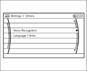
Black plate (186,1)
Model "Z51-D" EDITED: 2009/ 8/ 3
Return All Settings to Default:
Select this item, push the ENTER button and
choose “YES” if you want to return all settings to
the default.
SAA1566
Others settings (models with navigation
system)
The Others settings display will appear when
pushing the SETTING button, selecting the
“Others” key with the multi-function controller
and pushing the ENTER button.
Voice Recognition:
For the details of this item, see “NISSAN VOICE
RECOGNITION SYSTEM (models with naviga-
tion system)” later in this section.
Language/Units:
.Select Language
Choose the “Select Language” key and
push the ENTER button. Select “English” or
“Franc¸ais” for your favorite display appear-
ance.
If you select the “Franc¸ais” key, the French
language will be displayed, so please use
the French Owner’s Manual. To obtain a
French Owner’s Manual, see “OWNER’S
MANUAL/SERVICE MANUAL ORDER IN-
FORMATION” in the “9. Technical and
consumer information” section.
.Select Units
Choose the “Select Units” key and push
the ENTER button. Select “US” (Mile, 8F,
MPG) or “Metric” (km, 8C, L/100 km) for
your favorite display appearance.
4-18 Monitor, heater, air conditioner, audio, phone and voice recognition systems

Black plate (187,1)
Model "Z51-D" EDITED: 2009/ 8/ 3
SAA1092
Language/Units settings (models without
navigation system)
The Language/Units settings display will appear
when pushing the SETTING button, selecting
the “Language/Units”keywiththemulti-
function controller and pushing the ENTER
button.
Select Language:
Choose the “Select Language” key and push
the ENTER button. From the following display,
select “English”, “Franc¸ais” or “Espan
˜ol” for your
favorite display appearance.
Select Units:
Choose the “Select Units” key and push the
ENTER button. From the following display,
select “US” (Mile, 8F, MPG) or “Metric” (km,
8C, L/100 km) for your favorite display appear-
ance.
When the selector lever is shifted into the R
(Reverse) position, the monitor display shows
the view to the rear of the vehicle.
The system is designed as an aid to the driver in
detecting large stationary objects to help avoid
damaging the vehicle. The system will not detect
small objects below the bumper and may not
detect objects close to the bumper or on the
ground.
WARNING
.The rear view camera is a conve-
nience but it is not a substitute for
proper backing up. Always turn and
check that it is safe to do so before
backing up. Always back up slowly.
.Objects viewed in the RearView
Monitor differ from actual distance
because a wide-angle lens is used.
Objects in the RearView Monitor
will appear visually opposite than
when viewed in the rear view and
outside mirrors.
.Make sure that the lift gate is
securely closed when backing up.
.Underneath the bumper and the
corner areas of the bumper cannot
be viewed on the RearView Monitor
REARVIEW MONITOR (if so
equipped)
Monitor, heater, air conditioner, audio, phone and voice recognition systems 4-19

Black plate (188,1)
Model "Z51-D" EDITED: 2009/ 8/ 3
because of its monitoring range
limitation.
.Do not put anything on the rear view
camera. The rear view camera is
installed above the license plate.
.When washing the vehicle with
high-pressure water, be sure not to
spray it around the camera. Other-
wise, water may enter the camera
unit causing water condensation on
the lens, a malfunction, fire or an
electric shock.
.Do not strike the camera. It is a
precision instrument. Otherwise, it
may malfunction or cause damage
resulting in a fire or an electric
shock.
CAUTION
Do not scratch the camera lens when
cleaning dirt or snow from the lens.
SAA1896
HOW TO READ THE DISPLAYED
LINES
Guiding lines which indicate the vehicle width
and distances to objects with reference to the
vehicle body line *
Aare displayed on the
monitor.
Distance guide lines:
Indicate distances from the vehicle body.
.Red line *
1: approx. 1.5 ft (0.5 m)
.Yellow line *
2: approx. 3 ft (1 m)
.Green line *
3: approx. 7 ft (2 m)
.Green line *
4: approx. 10 ft (3 m)
Vehicle width guide lines *
5:
Indicate the vehicle width when backing up.
Predicted course lines *
6:
Indicate the predicted course when backing up.
The predicted course lines will be displayed on
the monitor when the selector lever is in the R
(Reverse) position and the steering wheel is
turned. The predicted course lines will move
depending on how much the steering wheel is
turned and will not be displayed while the
steering wheel is in the neutral position.
HOW TO PARK WITH PREDICTED
COURSE LINES
WARNING
.Always turn and check that it is safe
to do so before backing up. Always
back up slowly.
.Use the displayed lines as a refer-
ence. The lines are highly affected
by the number of occupants, fuel
level, vehicle position, road condi-
tion and road grade.
.If the tires are replaced with differ-
ent sized tires, the predicted course
line may be displayed incorrectly.
4-20 Monitor, heater, air conditioner, audio, phone and voice recognition systems

Black plate (189,1)
Model "Z51-D" EDITED: 2009/ 8/ 3
.On a snow-covered or slippery road,
there may be a difference between
the predicted course line and the
actual course line.
.If the battery is disconnected or
becomes discharged, the predicted
course lines may be displayed in-
correctly. If this occurs, please per-
form the following procedures:
— Turn the steering wheel from
lock to lock while the engine is
running.
— Drive the vehicle on a straight
road for more than 5 minutes.
.When the steering wheel is turned
with the ignition switch in the ACC
position, the predicted course lines
may be displayed incorrectly.
.The displayed lines will appear
slightly off to the right because the
rear view camera is not installed in
the rear center of the vehicle.
.The distance guide line and the
vehicle width line should be used
as a reference only when the vehicle
is on a level paved surface. The
distance viewed on the monitor is
for reference only and may be
different than the actual distance
between the vehicle and displayed
objects.
.When backing-up the vehicle up a
hill objects viewed in the monitor
are further than they appear. When
backing-up the vehicle down a hill,
objects viewed in the monitor are
closer than they appear. Use the
inside mirror or glance over your
shoulder to properly judge dis-
tances to other objects.
The vehicle width and predicted course
lines are wider than the actual width and
course.
SAA1897
1. Visually check that the parking space is safe
before parking your vehicle.
2. The rear view of the vehicle is displayed on
the screen *
Awhen the selector lever is
moved to the R (Reverse) position.
Monitor, heater, air conditioner, audio, phone and voice recognition systems 4-21
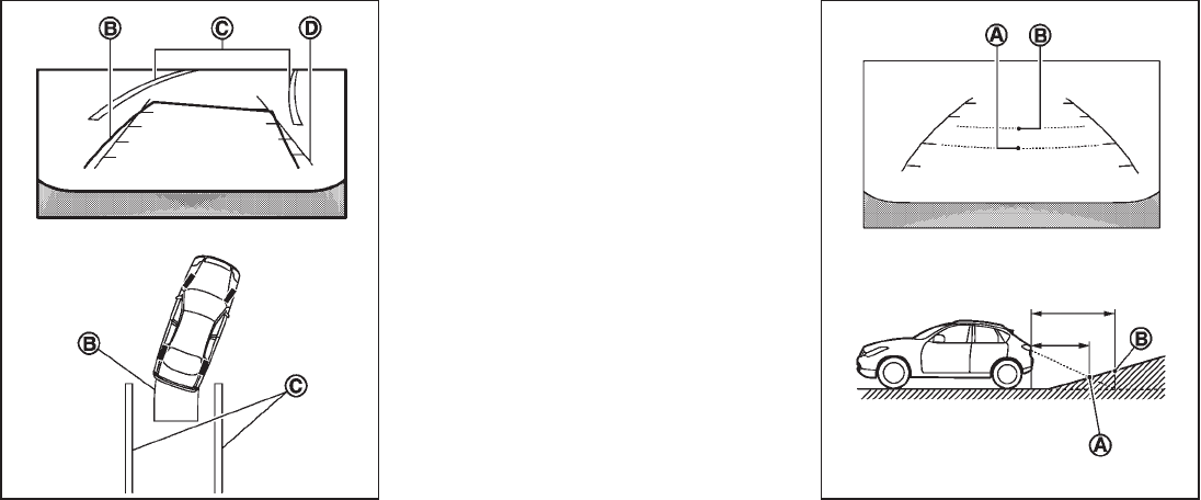
Black plate (190,1)
Model "Z51-D" EDITED: 2009/ 8/ 3
SAA1898
3. Slowly back up the vehicle adjusting the
steering wheel so that the predicted course
lines *
Benter the parking space *
C.
4. Maneuver the steering wheel to make the
vehicle width guide lines *
Dparallel to the
parking space *
Cwhile referring to the
predicted course lines.
5. When the vehicle is parked in the space
completely, move the selector lever to the P
(Park) position and apply the parking brake.
DIFFERENCE BETWEEN PREDICTED
AND ACTUAL DISTANCES
The distance guide line and the vehicle width
guide line should be used as a reference only
when the vehicle is on a level, paved surface.
The distance viewed on the monitor is for
reference only and may be different than the
actual distance between the vehicle and dis-
played objects.
SAA1978
Backing up on a steep uphill
When backing up the vehicle up a hill, the
distance guide lines and the vehicle width guide
lines are shown closer than the actual distance.
For example, the display shows 3 ft (1.0 m) to
the place *
A, but the actual 3 ft (1.0 m)
distance on the hill is the place *
B. Note that
4-22 Monitor, heater, air conditioner, audio, phone and voice recognition systems

Black plate (191,1)
Model "Z51-D" EDITED: 2009/ 8/ 3
any object on the hill is viewed in the monitor
further than it appears.
SAA1979
Backing up on a steep downhill
When backing up the vehicle down a hill, the
distance guide lines and the vehicle width guide
lines are shown further than the actual distance.
For example, the display shows 3 ft (1.0 m) to
the place *
A, but the actual 3 ft (1.0 m)
distance on the hill is the place *
B. Note that
any object on the hill is viewed in the monitor
closer than it appears.
Monitor, heater, air conditioner, audio, phone and voice recognition systems 4-23

Black plate (192,1)
Model "Z51-D" EDITED: 2009/ 8/ 3
SAA1923
Backing up near a projecting object
The predicted course lines *
Ado not touch the
object in the display. However, the vehicle may
hit the object if it projects over the actual
backing up course.
SAA1980
Backing up behind a projecting object
The position *
Cis shown further than the
position *
Bin the display. However, the
position *
Cis actually at the same distance
as the position *
A. The vehicle may hit the
object when backing up to the position *
Aif
the object projects over the actual backing up
course.
HOW TO ADJUST THE SCREEN
To adjust the Display ON/OFF, Brightness, Tint,
Color, Contrast and Black Level of the RearView
Monitor, push the SETTING button with the
RearView Monitor on, select the item key and
adjust the level using the multi-function con-
troller.
Do not adjust the Brightness, Tint, Color,
Contrast and Black Level of the RearView
Monitor while the vehicle is moving. Make sure
the parking brake is firmly applied and the
engine is not running.
OPERATING TIPS
.When the selector lever is shifted to the R
(Reverse) position, the monitor screen auto-
matically changes to the RearView Monitor
mode. However, the radio can be heard.
.It may take some time until the RearView
Monitor or the normal screen is displayed
after the selector lever has been shifted to R
from another position or to another position
from R. Objects may be distorted momenta-
rily until the RearView Monitor screen is
displayed completely.
.When the temperature is extremely high or
low, the screen may not clearly display
objects. This is not a malfunction.
4-24 Monitor, heater, air conditioner, audio, phone and voice recognition systems

Black plate (193,1)
Model "Z51-D" EDITED: 2009/ 8/ 3
.When strong light directly enters the cam-
era, objects may not be displayed clearly.
This is not a malfunction.
.Vertical lines may be seen in objects on the
screen. This is due to strong reflected light
from the bumper. This is not a malfunction.
.The screen may flicker under fluorescent
light. This is not a malfunction.
.The colors of objects on the RearView
Monitor may differ somewhat from those of
the actual object.
.Objects on the monitor may not be clear in a
dark place or at night. This is not a
malfunction.
.If dirt, rain or snow attaches to the camera,
the RearView Monitor may not clearly dis-
play objects. Clean the camera.
.Do not use alcohol, benzine or thinner to
clean the camera. This will cause discolora-
tion. To clean the camera, wipe with a cloth
dampened with diluted mild cleaning agent
and then wipe with a dry cloth.
.Do not damage the camera as the monitor
screen may be adversely affected.
.Do not use wax on the camera window.
Wipe off any wax with a clean cloth
dampened with mild detergent diluted with
water.
SAA1991
Center ventilators
SAA1990
Side ventilators
VENTILATORS
Monitor, heater, air conditioner, audio, phone and voice recognition systems 4-25

Black plate (194,1)
Model "Z51-D" EDITED: 2009/ 8/ 3
SAA1066
Rear (if so equipped)
Open or close, and adjust the air flow direction
of ventilators.
: This symbol indicates that the vents are
closed.
: This symbol indicates that the vents are
open.
WARNING
.The air conditioner cooling function
operates only when the engine is
running.
.Do not leave children or adults who
would normally require the support
of others alone in your vehicle. Pets
should not be left alone either. On
hot, sunny days, temperatures in a
closed vehicle could quickly become
high enough to cause severe or
possibly fatal injuries to people or
animals.
.Do not use the recirculation mode
for long periods as it may cause the
interior air to become stale and the
windows to fog up.
Start the engine and operate the heater and air
conditioner system.
You can individually set the driver and front
passenger side temperature using each tem-
perature control button.
SAA1520
For the models with the color display screen,
push the “STATUS” button to display the heater
and air conditioner status screen. (See “HOW
TO USE STATUS BUTTON” earlier in this
section.)
HEATER AND AIR CONDITIONER
4-26 Monitor, heater, air conditioner, audio, phone and voice recognition systems
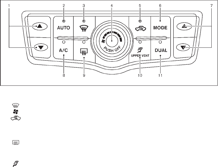
Black plate (195,1)
Model "Z51-D" EDITED: 2009/ 8/ 3
SAA2040
Type A
1. Temperature control button (driver side)
2. “AUTO” automatic climate control ON button
3. “ ” front defroster button
4. “ ” fan speed control dial/OFF button
5. “ ” intake air control button
6. “MODE” manual air flow control button
7. Temperature control button (passenger side)
8. “A/C” air conditioner ON/OFF button
9. “ ” rear window defroster button (See “REAR
WINDOW AND OUTSIDE MIRROR DEFROS-
TER SWITCH” in the “2. Instruments and con-
trols” section.)
10. “ ” upper vent system button
11. “DUAL” zone control ON/OFF button
Monitor, heater, air conditioner, audio, phone and voice recognition systems 4-27

Black plate (196,1)
Model "Z51-D" EDITED: 2009/ 8/ 3
SAA2834
Type B
1. “AUTO” automatic climate control ON button/
Temperature control dial (driver side)
2. “A/C” air conditioner ON/OFF button
3. “ ” intake air control button
4. “ ” fan speed control dial/ON/OFF button
5. “ ” upper vent system button
6. “DUAL” zone control ON/OFF button/Temperature
control dial (passenger side)
7. “ ” front defroster button
8. “ ” rear window defroster button (See “REAR
WINDOW AND OUTSIDE MIRROR DEFROS-
TER SWITCH” in the “2. Instruments and con-
trols” section.)
9. “MODE” manual air flow control button
AUTOMATIC OPERATION
Cooling and/or dehumidified heating
(AUTO)
This mode may be used all year round. The
system works automatically to control the inside
temperature, air flow distribution and fan speed
after the preferred temperature is set manually.
1. Push the “AUTO” button on. (The indicator
on the button will illuminate and AUTO will
be displayed.)
2. Operate the driver side temperature control
buttons (type A) or dial (type B) to set the
desired temperature.
Adjust the temperature to about 758F
(248C) for normal operation.
.The temperature of the passenger com-
partment will be maintained automati-
cally. Air flow distribution and fan speed
will also be controlled automatically.
3. You can individually set driver and front
passenger side temperature using each
temperature control button (type A) or dial
(type B). When the “DUAL” button is pushed
or the passenger side temperature control
buttons (type A) or dial (type B) is/are
operated, the DUAL indicator will come on.
To turn off the passenger side temperature
control, push the “DUAL” button.
A visible mist may be seen coming from the
ventilators in hot, humid conditions as the air is
cooled rapidly. This does not indicate a mal-
function.
Heating (A/C OFF)
The air conditioner does not activate in this
mode. When you need to heat only, use this
mode.
1. Push the “A/C” button. (The A/C indicator
will turn off.)
2. Operate the temperature control buttons
(type A) or dial (type B) to set the desired
temperature.
4-28 Monitor, heater, air conditioner, audio, phone and voice recognition systems

Black plate (197,1)
Model "Z51-D" EDITED: 2009/ 8/ 3
.The temperature of the passenger compart-
ment will be maintained automatically. Air
flow distribution and fan speed are also
controlled automatically.
.Do not set the temperature lower than the
outside air temperature. Otherwise the
system may not work properly.
.Not recommended if windows fog up.
Dehumidified defrosting or defogging
1. Push the “ ” front defroster button. (The
indicator light on the button will come on.)
2. Operate the temperature control buttons
(type A) dial (type B) to set the desired
temperature.
.To quickly remove ice from the outside of the
windows, turn the “ ” fan speed control
dial and set it to the maximum position.
.As soon as possible after the windshield is
clean, push the “AUTO” button to return to
the auto mode.
.When the “ ” front defroster button is
pushed, the air conditioner will automatically
be turned on at outside temperatures above
238F(−58C) to defog the windshield, and
the air recirculate mode will automatically be
turned off.
Outside air is drawn into the passenger
compartment to improve the defogging
performance.
MANUAL OPERATION
Fan speed control
Turn the “ ” fan speed control dial to
manually control the fan speed.
Push the “AUTO” button to return to automatic
control of the fan speed.
Air recirculation
Push the intake air control button “ ”to
recirculate interior air inside the vehicle. The
indicator light “ ” will come on.
The air recirculation mode cannot be activated
when the air conditioner is in the front defrosting
mode “ ”.
Outside air circulation
Push the intake air control button “ ”to
change the air circulation from the intake air to
the outside air. The indicator light “ ” will turn
off.
Automatic air intake control
In the AUTO mode, the intake air will be
controlled automatically. To manually control
the intake air, push the intake air control button
“”. To return to the automatic control mode,
push the intake air control button “ ” for
about 2 seconds. The indicator lights will flash
twice, and then the intake air will be controlled
automatically.
Air flow control
Pushing the “MODE” manual air flow control
button selects the air outlet to:
: Air flows from center and side ventila-
tors.
: Air flows from center and side ventila-
tors and foot outlets.
: Air flows mainly from foot outlets.
: Air flows from defroster and foot out-
lets.
Upper vent system
When the “ ” upper vent button is pushed,
the air flow against the driver’s or passenger’s
upper body becomes gentle. The indicator light
on the button will come on.
In this mode, air from the center ventilators flows
both straight and upward in order to control the
cabin temperature without blowing air directly
on the occupants.
If you want strong air flow against your upper
body, push the “ ” button to turn the
indicator light off.
Monitor, heater, air conditioner, audio, phone and voice recognition systems 4-29

Black plate (198,1)
Model "Z51-D" EDITED: 2009/ 8/ 3
TO TURN THE SYSTEM ON/OFF
Push the “OFF” or “ON·OFF” button when the
heater and air conditioner is off. The system will
turn on with the settings that were used
immediately before the system was turned off.
SAA1989
OPERATING TIPS
The sunload sensor *
Aon the instrument panel
helps maintain a constant temperature. Do not
put anything on or around this sensor.
IN-CABIN MICROFILTER
The air conditioning system is equipped with an
in-cabin microfilter which collects dirt, pollen,
dust, etc. To make sure the air conditioner heats,
defogs, and ventilates efficiently, replace the
filter in accordance with the maintenance
schedule in the NISSAN Service and Mainte-
nance Guide. To replace the filter, contact a
NISSAN dealer.
The filter should be replaced if air flow is
extremely decreased or when windows fog
up easily when operating heater or air
conditioning system.
SERVICING AIR CONDITIONER
The air conditioning system in your NISSAN is
charged with a refrigerant designed with the
environment in mind. This refrigerant will not
harm the earth’s ozone layer. However,
special charging equipment and lubricant are
required when servicing your NISSAN air con-
ditioner. Using improper refrigerants or lubri-
cants will cause severe damage to your air
conditioning system. (See “CAPACITIES AND
RECOMMENDED FUEL/LUBRICANTS” in the
“9. Technical and consumer information” section
for air conditioning system refrigerant and
lubricant recommendations.)
Your NISSAN dealer will be able to service your
environmentally friendly air conditioning system.
WARNING
The system contains refrigerant under
high pressure. To avoid personal injury,
any air conditioner service should be
done only by an experienced technician
with the proper equipment.
4-30 Monitor, heater, air conditioner, audio, phone and voice recognition systems

Black plate (199,1)
Model "Z51-D" EDITED: 2009/ 8/ 3
AUDIO OPERATION PRECAUTIONS
Radio
Push the ignition switch to the ACC or ON
position and push the “RADIO” button to turn
on the radio. If you listen to the radio with the
engine not running, the ignition switch should be
pushed to the ACC position.
Radio reception is affected by station signal
strength, distance from radio transmitter, build-
ings, bridges, mountains and other external
influences. Intermittent changes in reception
quality normally are caused by these external
influences.
Using a cellular phone in or near the
vehicle may influence radio reception
quality.
Radio reception:
Your NISSAN radio system is equipped with
state-of-the-art electronic circuits to enhance
radio reception. These circuits are designed to
extend reception range, and to enhance the
quality of that reception.
However there are some general characteristics
of both FM and AM radio signals that can affect
radio reception quality in a moving vehicle, even
when the finest equipment is used. These
characteristics are completely normal in a given
reception area, and do not indicate any mal-
function in your NISSAN radio system.
Reception conditions will constantly change
because of vehicle movement. Buildings, terrain,
signal distance and interference from other
vehicles can work against ideal reception.
Described below are some of the factors that
can affect your radio reception.
Some cellular phones or other devices may
cause interference or a buzzing noise to come
from the audio system speakers. Storing the
device in a different location may reduce or
eliminate the noise.
SAA0306
FM radio reception:
Range: FM range is normally limited to 25 to 30
miles (40 to 48 km), with monaural (single
channel) FM having slightly more range than
stereo FM. External influences may sometimes
interfere with FM station reception even if the
FM station is within 25 miles (40 km). The
strength of the FM signal is directly related to the
distance between the transmitter and receiver.
FM signals follow a line-of-sight path, exhibiting
many of the same characteristics as light. For
example they will reflect off objects.
Fade and drift: As your vehicle moves away from
a station transmitter, the signals will tend to fade
and/or drift.
AUDIO SYSTEM
Monitor, heater, air conditioner, audio, phone and voice recognition systems 4-31

Black plate (200,1)
Model "Z51-D" EDITED: 2009/ 8/ 3
Static and flutter: During signal interference from
buildings, large hills or due to antenna position,
usually in conjunction with increased distance
from the station transmitter, static or flutter can
be heard. This can be reduced by lowering the
treble setting to reduce the treble response.
Multipath reception: Because of the reflective
characteristics of FM signals, direct and re-
flected signals reach the receiver at the same
time. The signals may cancel each other,
resulting in momentary flutter or loss of sound.
AM radio reception:
AM signals, because of their low frequency, can
bend around objects and skip along the ground.
In addition, the signals can be bounced off the
ionosphere and bent back to earth. Because of
these characteristics. AM signals are also
subject to interference as they travel from
transmitter to receiver.
Fading: Occurs while the vehicle is passing
through freeway underpasses or in areas with
many tall buildings. It can also occur for several
seconds during ionospheric turbulence even in
areas where no obstacles exist.
Static: Caused by thunderstorms, electrical
power lines, electric signs and even traffic lights.
Satellite radio reception (if so equipped):
When the satellite radio is first installed or the
battery has been replaced, the satellite radio
may not work properly. This is not a malfunction.
Wait more than 10 minutes with satellite radio
ON for satellite radio to receive all of the
necessary data.
The satellite radio mode requires an active XM®
satellite radio service subscription. Satellite
radio is not available in Alaska, Hawaii and
Guam.
Satellite radio performance may be affected if
cargo carried on the roof blocks the satellite
radio signal.
If possible, do not put cargo near the satellite
antenna.
A build up of ice on the satellite radio antenna
can affect satellite radio performance. Remove
the ice to restore satellite radio reception.
SAA0480
Compact Disc (CD) player
.Do not force a compact disc into the CD
insert slot. This could damage the CD
and/or CD changer/player.
.Trying to load a CD with the CD door
closed could damage the CD and/or CD
4-32 Monitor, heater, air conditioner, audio, phone and voice recognition systems
Black plate (201,1)
Model "Z51-D" EDITED: 2009/ 8/ 3
changer.
.During cold weather or rainy days, the
player may malfunction due to the
humidity. If this occurs, remove the CD
and dehumidify or ventilate the player
completely.
.The player may skip while driving on
rough roads.
.The CD player sometimes cannot func-
tion when the passenger compartment
temperature is extremely high. De-
crease the temperature before use.
.Only use high quality 4.7 in (12 cm)
round discs that have the “COMPACT
disc DIGITAL AUDIO” logo on the disc
or packaging.
.Do not expose the CD to direct sun-
light.
.CDs that are of poor quality, dirty,
scratched, covered with fingerprints,
or that have pin holes may not work
properly.
.The following CDs may not work prop-
erly:
—Copy control compact discs (CCCD)
—Recordable compact discs (CD-R)
—Rewritable compact discs (CD-RW)
.Do not use the following CDs as they
may cause the CD player to malfunc-
tion.
—3.1 in (8 cm) discs
—CDs that are not round
—CDs with a paper label
—CDs that are warped, scratched, or
have abnormal edges
.This audio system can only play pre-
recorded CDs. It has no capabilities to
record or burn CDs.
.If the CD cannot be played, one of the
following messages will be displayed.
CHECK DISC:
—Confirm that the CD is inserted
correctly (the label side is facing up,
etc.).
—Confirm that the CD is not bent or
warped and it is free of scratches.
PUSH EJECT:
This is an error due to the temperature
inside the player is too high. Remove
the CD by pushing the EJECT button,
and after a short time reinsert the CD.
The CD can be played when the tem-
perature of the player returns to nor-
mal.
UNPLAYABLE:
The file is unplayable in this audio
system (only MP3 or WMA CD).
CompactFlash (CF) player (if so
equipped)
.Do not force a CF card into the slot.
This could damage the CF card and/or
player.
.During cold weather or rainy days, the
player may malfunction due to the
humidity. If this occurs, remove the CF
card and dehumidify or ventilate the
player completely.
.The CF player sometimes cannot func-
tion when the passenger compartment
temperature is extremely high. De-
crease the temperature before use.
.Do not expose a CF card to direct
sunlight.
.Confirm that a CF card is inserted
correctly.
Monitor, heater, air conditioner, audio, phone and voice recognition systems 4-33
Black plate (202,1)
Model "Z51-D" EDITED: 2009/ 8/ 3
iPod®player (if so equipped)
.Some characters used in other lan-
guages (Chinese, Japanese, etc.) are
not displayed properly on the vehicle
center screen. We recommend using
English language characters with an
iPod®.
.Large video podcast files cause slow
responses in the iPod®. The vehicle
center display may momentarily black
out, but it will soon recover.
.If the iPod®automatically selects large
video podcast files while in the shuffle
mode, the vehicle center display may
momentarily black out, but it will soon
recover.
.Improperly plugging in the iPod®may
cause a checkmark to be displayed on
and off (flickering). Always make sure
that the iPod®is connected properly.
.The iPod®nano (2nd Generation) will
continue to fast forward or rewind if it
is disconnected during a seek opera-
tion.
.An incorrect song title may appear
when the Play Mode is changed while
using the iPod®nano (2nd Generation).
.Audiobooks may not play in the same
order as they appear on the iPod®.
.The iPod®nano (1st Generation) may
remain in fast forward or rewind mode
if it is connected during a seek opera-
tion. In this case, please manually reset
the iPod®.
.If you are using an iPod®(3rd Genera-
tion with Dock connector), do not use
very long names for the song title,
album name or artist name to avoid
the iPod®from resetting itself.
.Be careful not to do the following, or
the cable could be damaged and a loss
of function may occur.
—Bend the cable excessively (1.6 in (40
mm) radius minimum).
—Twist the cable excessively (more
than 180 degrees).
—Pull or drop the cable.
—Close the center console lid on the
cable or connectors.
—Store objects with sharp edges in the
storage where the cable is stored.
—Spill liquids on the cable and con-
nectors.
.Do not connect the cable to the iPod®if
the cable and/or connectors are wet. It
may damage the iPod®.
.If the cable and connectors are ex-
posed to water, allow the cable and/or
connectors to dry completely before
connecting the cable to the iPod®(wait
24 hours for it to dry).
.If the connector is exposed to fluids
other than water, evaporative residue
may cause a short between the con-
nector pins. In this case, replace the
cable, otherwise damage to the iPod®
and a loss of function may occur.
.If the cable is damaged (insulation cut,
connectors cracked, contamination
such as liquids, dust, dirt, etc. in the
connectors), do not use the cable and
contact a NISSAN dealer to replace the
cable with a new one.
.When not in use for extended periods
of time, store the cable in a clean, dust
free environment at room temperature
and without direct sun exposure.
.Do not use the cable for any other
purposes other than its intended use in
the vehicle.
.iPod®charging is only possible for
devices that support charging via a
FireWire®connection. Devices that can
4-34 Monitor, heater, air conditioner, audio, phone and voice recognition systems
Black plate (203,1)
Model "Z51-D" EDITED: 2009/ 8/ 3
be charged by the iPod player include:
—iPod®Classic - 1st through 6th gen-
eration
—iPod®Mini - 1st and 2nd generation
—iPod®Nano - 1st through 3rd genera-
tion only
—iPod®Touch - first generation only
—iPhone®- first generation only
* The iPod®Classic and iPod®Touch may
not charge properly in some cases.
* 12V charging is not possible on the
iPhone 3G and later models.
* iPod®and FireWire®are trademarks of
Apple Inc., registered in the U.S. and
other countries.
Compact Disc (CD)/CompactFlash (CF)
with MP3 or WMA
Explanation of terms:
.MP3 — MP3 is short for Moving Pictures
Experts Group Audio Layer 3. MP3 is the
most well known compressed digital audio
file format. This format allows for near “CD
quality” sound, but at a fraction of the size of
normal audio files. MP3 conversion of an
audio track from CD/CF can reduce the file
size by approximately 10:1 ratio (Sampling:
44.1 kHz, Bit rate: 128 kbps) with virtually
no perceptible loss in quality. MP3 com-
pression removes the redundant and irrele-
vant parts of a sound signal that the human
ear doesn’t hear.
.WMA — Windows Media Audio (WMA) is a
compressed audio format created by Micro-
soft as an alternative to MP3. The WMA
codec offers greater file compression than
the MP3 codec, enabling storage of more
digital audio tracks in the same amount of
space when compared to MP3s at the same
level of quality.
.Bit rate — Bit rate denotes the number of
bits per second used by a digital music files.
The size and quality of a compressed digital
audio file is determined by the bit rate used
when encoding the file.
.Sampling frequency — Sampling frequency
is the rate at which the samples of a signal
are converted from analog to digital (A/D
conversion) per second.
.Multisession — Multisession is one of the
methods for writing data to media. Writing
data once to the media is called a single
session, and writing more than once is
called a multisession.
.ID3/WMA Tag — The ID3/WMA tag is the
part of the encoded MP3 or WMA file that
contains information about the digital music
file such as song title, artist, album title,
encoding bit rate, track time duration, etc.
ID3 tag information is displayed on the
Album/Artist/Track title line on the display.
* Windows®and Windows Media®are regis-
tered trademarks or trademarks of Microsoft
Corporation in the United States of America
and/or other countries.
CompactFlash is a trademark of SanDisk
Corporation in the United States of America
and/or other countries.
Monitor, heater, air conditioner, audio, phone and voice recognition systems 4-35

Black plate (204,1)
Model "Z51-D" EDITED: 2009/ 8/ 3
SAA1025
Playback order:
Music playback order of the CD/CF with MP3 or
WMA is as illustrated above.
.The folder names of folders not containing
MP3/WMA files are not shown in the
display.
.If there is a file in the top level of the disc,
“Root Folder” is displayed.
.The playback order is the order in which the
files were written by the writing software, so
the files might not play in the desired order.
4-36 Monitor, heater, air conditioner, audio, phone and voice recognition systems

Black plate (205,1)
Model "Z51-D" EDITED: 2009/ 8/ 3
Specification chart:
Supported media CD, CD-R, CD-RW, CF
Supported file systems
CD, CD-R, CD-RW: ISO9660 LEVEL1, ISO9660 LEVEL2, Romeo, Joliet
* ISO9660 Level 3 (packet writing) is not supported.
* Files saved using the Live File System component (on a Windows Vista-based computer) are not
supported.
CompactFlash card: FAT12, FAT16, FAT32
Supported
versions*1
MP3
Version MPEG1, MPEG2, MPEG2.5
Sampling frequency 8 kHz - 48 kHz
Bit rate 8 kbps - 320 kbps, VBR*4
WMA*2
Version WMA7, WMA8, WMA9
Sampling frequency 32 kHz - 48 kHz
Bit rate 32 kbps - 192 kbps, VBR*4
Tag information (Song title and Artist name) ID3 tag VER1.0, VER1.1, VER2.2, VER2.3, VER2.4 (MP3 only)
WMA tag (WMA only)
Folder levels
With navigation system:
Folder levels: 8, Folders: 255 (including root folder), Files: 512 (Max. 255 files for one folder)
Without navigation system:
Folder levels: 8, Folders and files: 999 (Max. 255 files for one folder)
Text character number limitation With navigation system: 128 characters
Without navigation system: 64 characters
Displayable character codes*3 01: ASCII, 02: ISO-8859-1, 03: UNICODE (UTF-16 BOM Big Endian), 04: UNICODE (UTF-16 Non-BOM
Big Endian), 05: UNICODE (UTF-8), 06: UNICODE (Non-UTF-16 BOM Little Endian)
*1 Files created with a combination of 48 kHz sampling frequency and 64 kbps bit rate cannot be played.
*2 Protected WMA files (DRM) cannot be played.
*3 Available codes depend on what kind of media, versions and information are going to be displayed.
*4 When VBR files are played, the playback time may not be displayed correctly.
Monitor, heater, air conditioner, audio, phone and voice recognition systems 4-37

Black plate (206,1)
Model "Z51-D" EDITED: 2009/ 8/ 3
Troubleshooting guide:
Symptom Cause and Countermeasure
Cannot play
Check if the CD/CF was inserted correctly.
Check if the CD/CF is scratched or dirty.
Check if there is condensation inside the player, and if there is, wait until the condensation is gone (about 1 hour) before
using the player.
If there is a temperature increase error, the player will play correctly after it returns to the normal temperature.
If there is a mixture of music CD files (CD-DA data) and MP3/WMA files on a CD, only the music CD files (CD-DA data)
will be played.
Files with extensions other than “.MP3”, “.WMA”, “.mp3” or “.wma” cannot be played. In addition, the character codes
and number of characters for folder names and file names should be in compliance with the specifications.
Check if the disc or the file is generated in an irregular format. This may occur depending on the variation or the setting of
MP3/WMA writing applications or other text editing applications.
Check if the finalization process, such as session close and disc close, is done for the disc.
Check if the CD/CF is protected by copyright.
Poor sound quality Check if the CD/CF is scratched or dirty.
It takes a relatively long time before the music
starts playing.
If there are many folder or file levels on the MP3/WMA CD/CF, or if it is a multisession disc, some time may be required
before the music starts playing.
Music cuts off or skips The writing software and hardware combination might not match, or the writing speed, writing depth, writing width, etc.,
might not match the specifications. Try using the slowest writing speed.
Skipping with high bit rate files Skipping may occur with large quantities of data, such as for high bit rate data.
Move immediately to the next song when playing. When a non-MP3/WMA file has been given an extension of “.MP3”, “.WMA”, “.mp3” or “.wma”, or when play is
prohibited by copyright protection, the player will skip to the next song.
The songs do not play back in the desired order. The playback order is the order in which the files were written by the writing software, so the files might not play in the
desired order.
4-38 Monitor, heater, air conditioner, audio, phone and voice recognition systems

Black plate (207,1)
Model "Z51-D" EDITED: 2009/ 8/ 3
SAA2010
1. CD EJECT button
2. ON·OFF/VOLUME control knob
3. Radio station and CD selector buttons
4. CD LOAD button
5. Radio tuning / MP3/WMA folder selector / AUDIO
control knob
6. AM·FM band select button
7. DISC button
8. AUX button
9. DISP (display) change/CLOCK button
10. Radio/CD SCAN (tuning) button
11. CD RPT (repeat)/RDM (random) play button
12. REW (rewind) button for SEEK/TRACK
13. FF (fast forward) button for SEEK/TRACK
14. AUX jack
FM-AM RADIO WITH COMPACT DISC
(CD) CHANGER
For all operation precautions, see “AUDIO
OPERATION PRECAUTIONS” earlier in this
section.
Audio main operation
Head unit:
The radio has an FM diversity reception system,
which employs two antennas printed on the rear
window. This system automatically switches to
the antenna which is receiving less interference.
The auto loudness circuit enhances the low and
high frequency ranges automatically in both
radio reception and CD playback.
ON·OFF/Volume control:
Push the ignition switch to the ACC or ON
position, and then push the ON·OFF/VOLUME
control knob while the system is off to call up the
mode (radio, CD or AUX) which was playing
immediately before the system was turned off.
While the system is on, pushing the ON·OFF/
VOLUME control knob turns the system off.
Turn the ON·OFF/VOLUME control knob to
adjust the volume.
Monitor, heater, air conditioner, audio, phone and voice recognition systems 4-39

Black plate (208,1)
Model "Z51-D" EDITED: 2009/ 8/ 3
Adjusting sound quality:
Push the Audio control knob to change the
selecting mode as follows.
Bass ?Treble ?Fade ?Balance ?Beep
Rotate the Audio control knob to adjust Bass,
Treble, Fade and Balance to the desired level.
Fade adjusts the sound level between the front
and rear speakers and Balance adjusts the
sound between the right and left speakers.
To turn the beep sound off or on, rotate the
Audio control knob until the desired mode is
displayed. This turns on or off the beep sound
when audio buttons are pushed.
Once you have adjusted the sound quality to the
desired level, push the Audio control knob
repeatedly until the radio or CD display re-
appears. Otherwise, the radio or CD display will
automatically reappear after about 5 seconds.
CLOCK adjust:
Push the CLOCK adjust button for more than
1.5 seconds to turn on the CLOCK display.
See “CLOCK” in the “2. Instruments and
controls” section for the detailed clock adjust-
ment operation.
AM-FM radio operation
radio (FM/AM) band select:
Pushing the radio band select button will
change the band as follows:
AM ?FM1 ?FM2 ?AM
When the radio band select button is pushed
while the ignition switch is in the ACC or ON
position, the radio will come on at the station last
played.
The last station/channel played will also come
on when the ON·OFF/VOL control knob is
pushed to ON.
If another audio source is playing when the radio
band select button is turned to ON, the audio
source will automatically be turned off and the
last radio station played will come on.
When the stereo broadcast signal is weak, the
radio will automatically change from stereo to
monaural reception.
TUNE (Tuning):
Turn the TUNE/FOLDER knob for manual tuning.
SEEK tuning:
Push the SEEK·CAT or TRACK button or
to tune from low to high or high to low
frequencies and to stop at the next broadcasting
station.
SCAN tuning:
Push the SCAN tuning button to tune from low
to high frequencies and stops at each broad-
casting station for 5 seconds. Pushing the
button again during this 5 seconds period will
stop SCAN tuning and the radio will remain
tuned to that station.
If the SCAN tuning button is not pushed within 5
seconds, SCAN tuning moves to the next
station.
*
1to *
6Station memory operations:
Twelve stations/channels can be set for the FM
band (6 for FM1, 6 for FM2) and 6 stations can
be set for the AM band.
1. Choose the radio band AM, FM1 or FM2
using the radio band select button.
2. Tune to the desired station using the SEEK,
SCAN or TUNE button.
3. Select the desired station/channel and keep
pushing any of the desired station preset
4-40 Monitor, heater, air conditioner, audio, phone and voice recognition systems

Black plate (209,1)
Model "Z51-D" EDITED: 2009/ 8/ 3
buttons *
1to *
6until a beep sound is
heard. (The radio mutes when the select
button is pushed.)
4. The channel indicator will then come on and
the sound will resume. Memorizing is now
complete.
5. Other buttons can be set in the same
manner.
If the battery cable is disconnected, or if the fuse
blows, the radio memory will be erased. In that
case, reset the desired stations.
Compact Disc (CD) changer operation
Push the ignition switch to the ACC or ON
position, push the LOAD button and insert the
compact disc into the slot with the label side
facing up. The compact disc will be guided
automatically into the slot and start playing.
After loading the disc, the number of tracks on
the disc and the play time will appear on the
display.
If the radio is already operating, it will auto-
matically turn off and the compact disc will play.
If the system has been turned off while the
compact disc was playing, pushing the
ON·OFF/VOL control knob will start the com-
pact disc.
CD LOAD:
To insert a CD in the CD changer, push the
LOAD button for less than 1.5 seconds. Select
the loading position by pushing the CD insert
select button *
1to *
6, then insert the CD.
To insert 6 CDs to the CD changer in
succession, push the LOAD button for more
than 1.5 seconds.
The inserted slot numbers will illuminate on the
display.
PLAY:
When the DISC (CD play) button is pushed with
the system off and the compact disc loaded, the
system will turn on and the compact disc will
start to play.
When the DISC button is pushed with the
compact disc loaded and the radio playing, the
radio will automatically be turned off and the
compact disc will start to play.
CD PLAY INFORMATION:
When the DISP button is pushed for less than
1.5 seconds while the CD is being played, the
disc information display will change as follows:
CD:
CD with MP3 or WMA:
FF (Fast Forward), REW (Re-
wind)/APS (Automatic Pro-
gram Search) FF, APS REW:
When the (fast forward) or (rewind)
button is pushed for more than 1.5 seconds
while the compact disc is being played, the
compact disc will play while fast forwarding or
rewinding. When the button is released, the
compact disc will return to normal play speed.
When the or button is pushed for less
than 1.5 seconds while the compact disc is
being played, the next track or the beginning of
Monitor, heater, air conditioner, audio, phone and voice recognition systems 4-41

Black plate (210,1)
Model "Z51-D" EDITED: 2009/ 8/ 3
the current track on the CD will be played.
CD PLAY selection:
To change to another CD already loaded into the
player, push the CD play select buttons *
1to
*
6.
REPEAT (RPT), RANDOM (RDM):
When the RPT button is pushed while the
compact disc is played, the play pattern can be
changed as follows:
(CD)
(CD with MP3 or WMA)
CD EJECT:
When the CD EJECT button is pushed with the
compact disc loaded, the compact disc will be
ejected.
To eject the discs selected by the CD select
button, push the EJECT button for less than 1.5
seconds.
To eject all the discs, push the EJECT button for
more than 1.5 seconds.
When this button is pushed while the compact
disc is being played, the compact disc will come
out and the system will turn off.
If the compact disc comes out and is not
removed, it will be pulled back into the slot
to protect it.
SCAN tuning:
When the SCAN tuning button is pushed for
less than 1.5 seconds while the CD is being
played, the beginning of all the tracks of CDs will
be played for 10 seconds in sequence.
When the SCAN tuning button is pushed for
more than 1.5 seconds while the CD is being
played, the first program in all the CDs will be
played for 10 seconds.
Pushing the button again during this 10 second
period will stop SCAN tuning.
If the SCAN tuning button is not pushed within
10 seconds, SCAN tuning moves to the next
disc program.
AUX (Auxiliary) button:
The AUX IN jack is located on the audio unit.
The AUX IN audio input jack accepts any
standard analog audio input such as from a
portable cassette tape/CD player, MP3 player or
laptop computers.
Push the AUX button to play a compatible
device when it is plugged into the AUX IN jack.
4-42 Monitor, heater, air conditioner, audio, phone and voice recognition systems

Black plate (211,1)
Model "Z51-D" EDITED: 2009/ 8/ 3
SAA1850
1. CD EJECT button
2. ON·OFF/VOLUME control knob
3. Radio station and CD selector buttons
4. CD LOAD button (if so equipped)
5. Radio tuning / MP3/WMA folder selector / AUDIO
control knob
6. Radio SCAN (tuning) button
7. CD RPT (repeat)/RDM (random) play button
8. Radio CAT (category)/REW (rewind) button for
SEEK/TRACK
9. FF (fast forward) button for SEEK/TRACK
10. CompactFlash (CF) card slot (models with navi-
gation system)
No satellite radio reception is available unless
optional satellite receiver and antenna are
installed and an XM®satellite radio service
subscription is active.
Monitor, heater, air conditioner, audio, phone and voice recognition systems 4-43

Black plate (212,1)
Model "Z51-D" EDITED: 2009/ 8/ 3
SAA1851
With navigation system
1. AM·FM band select button
2. SAT button
3. DISC·AUX button
SAA1852
Without navigation system
1. AM·FM band select button
2. DISC button
3. AUX/SAT band select button
FM-AM-SAT RADIO WITH COMPACT
DISC (CD) CHANGER
For all operation precautions, see “AUDIO
OPERATION PRECAUTIONS” earlier in this
section.
The satellite radio mode requires an active XM®
satellite radio service subscription. The satellite
radio is not available in Alaska, Hawaii and
Guam.
It may take some time to receive the activation
signal after subscribing to the XM®satellite
radio. After receiving the activation signal, an
available channel list will be automatically
updated in the radio. For XM®, push the ignition
switch from LOCK to ACC to update the
channel list.
Audio main operation
Head unit:
The radio has an FM diversity reception system,
which employs two antennas printed on the rear
window. This system automatically switches to
the antenna which is receiving less interference.
The auto loudness circuit enhances the low and
high frequency ranges automatically in both
radio reception and CD playback.
4-44 Monitor, heater, air conditioner, audio, phone and voice recognition systems

Black plate (213,1)
Model "Z51-D" EDITED: 2009/ 8/ 3
ON·OFF/Volume control:
Push the ignition switch to the ACC or ON
position, and then push the ON·OFF/VOLUME
control knob while the system is off to call up the
mode (radio, CD or AUX) which was playing
immediately before the system was turned off.
While the system is on, pushing the ON·OFF/
VOLUME control knob turns the system off.
Turn the ON·OFF/VOLUME control knob to
adjust the volume.
Adjusting tone quality and speaker bal-
ance:
To adjust Bass, Treble, Balance and Fade, push
the Audio control knob. When the display shows
the setting you want to change (Bass, Treble,
Balance and Fade), rotate the Audio control
knob to set the desired setting. For the other
setting methods, see “HOW TO USE SETTING
BUTTON” earlier in this section.
This vehicle has some sound effect functions as
follows (if so equipped):
.Speed Sensitive Volume
For more details, see “VEHICLE INFORMATION
AND SETTINGS” earlier in this section.
Switching the display (for models with
navigation system):
Pushing the DISC·AUX button will switch the
displays as follows:
CD ?CompactFlash* ?DVD* ?AUX ?
iPod®*?Music Box* ?CD
*: if so equipped
AM-FM-SAT radio operation
radio (FM/AM) band select:
Pushing the radio band select button will
change the band as follows:
AM ?FM1 ?FM2 ?AM
or radio (SAT) band select:
Pushing the radio band select button will
change the band as follows:
(With navigation system)
SAT1 ?SAT2 ?SAT1
(Without navigation system)
AUX ?SAT1 ?SAT2 ?AUX
When the radio band select button is pushed
while the ignition switch is in the ACC or ON
position, the radio will come on at the station last
played.
The last station/channel played will also come
on when the ON·OFF/VOL control knob is
pushed to ON.
The satellite radio mode requires an active XM®
satellite radio service subscription. Satellite
radio is not available in Alaska, Hawaii and
Guam.
If another audio source is playing when the radio
band select button is turned to ON, the audio
source will automatically be turned off and the
last radio station played will come on.
When the stereo broadcast signal is weak, the
radio will automatically change from stereo to
monaural reception.
TUNE (Tuning):
.For AM and FM radio
Turn the TUNE/FOLDER knob for manual
tuning.
.For XM satellite radio
Turn the TUNE/FOLDER knob to seek
channels from all of the categories when
any CAT is not selected.
SEEK tuning/CATEGORY
(CAT):
.For AM and FM radio
Push the SEEK·CAT or TRACK button
or to tune from low to high or high to
Monitor, heater, air conditioner, audio, phone and voice recognition systems 4-45

Black plate (214,1)
Model "Z51-D" EDITED: 2009/ 8/ 3
low frequencies and to stop at the next
broadcasting station.
.For XM satellite radio
Push the SEEK·CAT or TRACK button
or to tune to the first channel of the
next or previous category.
During satellite radio reception, the following
notices will be displayed under certain condi-
tions.
.NO SIGNAL (No signal is received while the
SAT tuner is connected.)
.OFF AIR (Broadcasting signed off)
.ANTENNA ERROR (Antenna connection
error)
.LOADING (When the initial setting is
performed)
.UPDATING (When the satellite radio sub-
scription is not active)
.INVALID CH (Invalid channel is received.)
SCAN tuning:
Push the SCAN tuning button to tune from low
to high frequencies and stops at each broad-
casting station for 5 seconds. Pushing the
button again during this 5 seconds period will
stop SCAN tuning and the radio will remain
tuned to that station.
If the SCAN tuning button is not pushed within 5
seconds, SCAN tuning moves to the next
station.
*
1to *
6Station memory operations:
Twelve stations/channels can be set for the FM
band (6 for FM1, 6 for FM2) and the SAT radio
(6 for SAT1, 6 for SAT2), and 6 stations can be
set for the AM band.
1. Choose the radio band using the radio band
select button.
2. Tune to the desired station using the SEEK,
SCAN or TUNE button.
3. Select the desired station/channel and keep
pushing any of the desired station preset
buttons *
1to *
6until a beep sound is
heard. (The radio mutes when the select
button is pushed.)
4. The channel indicator will then come on and
the sound will resume. Memorizing is now
complete.
5. Other buttons can be set in the same
manner.
If the battery cable is disconnected, or if the fuse
blows, the radio memory will be erased. In that
case, reset the desired stations.
Text:
When the “Text” key is selected with the multi-
function controller on the display and then the
ENTER button is pushed while the satellite radio
is being played, the text information will be
displayed on the screen.
.CH Name
.Category
.Name
.Title
.Other
Compact Disc (CD) player/changer op-
eration
Push the ignition switch to the ACC or ON
position, push the LOAD button (if so equipped)
and insert the compact disc into the slot with the
label side facing up. The compact disc will be
guided automatically into the slot and start
playing.
After loading the disc, the number of tracks on
the disc and the play time will appear on the
display.
If the radio is already operating, it will auto-
matically turn off and the compact disc will play.
If the system has been turned off while the
compact disc was playing, pushing the
4-46 Monitor, heater, air conditioner, audio, phone and voice recognition systems

Black plate (215,1)
Model "Z51-D" EDITED: 2009/ 8/ 3
ON·OFF/VOL control knob will start the com-
pact disc.
CD LOAD (if so equipped):
To insert a CD in the CD changer, push the
LOAD button for less than 1.5 seconds. Select
the loading position by pushing the CD insert
select button *
1to *
6, then insert the CD.
To insert 6 CDs to the CD changer in
succession, push the LOAD button for more
than 1.5 seconds.
The inserted slot numbers will illuminate on the
display.
or PLAY:
When the DISC (CD play) button is pushed with
the system off and the compact disc loaded, the
system will turn on and the compact disc will
start to play.
When the DISC button is pushed with the
compact disc loaded and the radio playing, the
radio will automatically be turned off and the
compact disc will start to play.
When the DISC button is pushed while a CD is
loaded and a medium is played using the
auxiliary input jacks, you can toggle back and
forth between CD and medium.
Text:
When the “Text” key is selected in the screen
using the multi-function controller and then the
ENTER button is pushed while the CD is being
played, the music information below will be
displayed on the screen.
CD:
.Disc title
.Track title
CD with MP3 or WMA:
.Folder title
.File title
.Song title
.Album title
.Artist
FF (Fast Forward), REW (Re-
wind)/APS (Automatic Pro-
gram Search) FF, APS REW:
When the (fast forward) or (rewind)
button is pushed for more than 1.5 seconds
while the compact disc is being played, the
compact disc will play while fast forwarding or
rewinding. When the button is released, the
compact disc will return to normal play speed.
When the or button is pushed for less
than 1.5 seconds while the compact disc is
being played, the next track or the beginning of
the current track on the CD will be played.
The multi-function controller can also be used to
select tracks when a CD is being played.
CD PLAY selection (if so equipped):
To change to another CD already loaded into the
player, push the CD play select buttons *
1to
*
6or choose a disc displayed on the screen
using the multi-function controller.
REPEAT (RPT), RANDOM (RDM):
When the RPT button is pushed while the
compact disc is played, the play pattern can be
changed as follows:
(CD)
(CD with MP3 or WMA)
Monitor, heater, air conditioner, audio, phone and voice recognition systems 4-47

Black plate (216,1)
Model "Z51-D" EDITED: 2009/ 8/ 3
CD EJECT:
When the CD EJECT button is pushed with the
compact disc loaded, the compact disc will be
ejected.
To eject the discs selected by the CD select
button, push the EJECT button for less than 1.5
seconds.
To eject all the discs (if so equipped), push the
EJECT button for more than 1.5 seconds.
When this button is pushed while the compact
disc is being played, the compact disc will come
out and the system will turn off.
If the compact disc comes out and is not
removed, it will be pulled back into the slot
to protect it.
SAA1856
Auxiliary input jacks
The auxiliary input jacks are located on the rear
side of the center console. NTSC compatible
devices such as video games, camcorders and
portable video players can be connected to the
auxiliary jacks. Compatible audio devices, such
as some MP3 players, can also be connected to
the system through the auxiliary jacks.
The auxiliary jacks are color coded for identifica-
tion purposes.
.Yellow - video input
.White - left channel audio input
.Red - right channel audio input
Before connecting a device to a jack, turn off the
power of the portable device.
With a compatible device connected to the
jacks, push the AUX button repeatedly until the
display switches to the AUX mode. The output
from the device will be played through the
monitor and audio system.
4-48 Monitor, heater, air conditioner, audio, phone and voice recognition systems

Black plate (217,1)
Model "Z51-D" EDITED: 2009/ 8/ 3
SAA1567
Display Mode:
The AUX settings display will appear when the
“Setting” key is selected using the multi-
function controller and pushing the ENTER
button.
Choose the display mode from the following:
.Normal
.Wide
.Cinema
SAA1862
COMPACTFLASH (CF) PLAYER OP-
ERATION (models with navigation sys-
tem)
Audio main operation
Push the ignition switch to the ACC or ON
position, remove the cover *
Aand insert a CF
card *
Binto the slot. Then, push the
button repeatedly to switch to the Compact-
Flash mode.
If the system has been turned off while the
CompactFlash card was playing, pushing the
ON·OFF/VOL control knob will start the Com-
pactFlash card.
PLAY:
When the DISC button is pushed with the
system off and the CF card inserted, the system
will turn on.
If another audio source is playing and a CF card
is inserted, push the DISC button repeatedly
until the center display changes to the Com-
pactFlash mode.
Text:
When the “Text” key is selected on the screen
using the multi-function controller and then the
ENTER button is pushed while the CF is being
played, the music information below will be
displayed on the screen.
.Folder title
.Song title
.Track title
.Album Title
.Artist
Monitor, heater, air conditioner, audio, phone and voice recognition systems 4-49

Black plate (218,1)
Model "Z51-D" EDITED: 2009/ 8/ 3
FF (Fast Forward), REW (Re-
wind)/APS (Automatic Pro-
gram Search) FF, APS REW:
When the (fast forward) or (rewind)
button is pushed for more than 1.5 seconds
while the CompactFlash card is being played,
the CompactFlash card will play while fast
forwarding or rewinding. When the button is
released, the CompactFlash card will return to
the normal play speed.
When the or button is pushed for less
than 1.5 seconds while the CompactFlash card
is being played, the next track or the beginning
of the current track on the CF will be played.
The multi-function controller can also be used to
select tracks when the CompactFlash card is
being played.
Folder selection:
To change to another folder in the Compact-
Flash card, turn the MP3/WMA folder selector
or choose a folder displayed on the screen using
the multi-function controller.
REPEAT (RPT), RANDOM (RDM):
When the RPT button is pushed while the
CompactFlash card is played, the play pattern
can be changed as follows:
CF EJECT:
When the knob next to the CF slot is pushed
with the CF card inserted, the CF card will be
ejected.
Messages:
The following messages will be displayed under
certain conditions.
.Reading Compact Flash (The system is
reading the CF card inserted in the slot.)
.No Compact Flash card (A CF card is not
inserted in the slot.)
.Compact Flash read error (The system
cannot read a CF card.)
.Unplayable file (The system cannot play a
music file.)
.No audio file (The CF card inserted in the
slot or its folder does not contain any music
files.)
SAA1853
Type A
SAA2011
Type B
4-50 Monitor, heater, air conditioner, audio, phone and voice recognition systems
Black plate (219,1)
Model "Z51-D" EDITED: 2009/ 8/ 3
iPod®PLAYER OPERATION (if so
equipped)
Connecting iPod®
Open the console lid and connect the cable *
1
as illustrated, and then connect the other end of
the cable to your iPod®*
2. Your vehicle is
equipped with the specialized cable for con-
necting the iPod®to your vehicle audio unit. The
battery of your iPod®is charged while it is
connected to the vehicle if the iPod®supports
charging via a FireWire®connection.
The display on the iPod®shows a NISSAN
screen when the connection is completed.
While connecting the iPod®to the vehicle, the
iPod®can only be operated by the vehicle audio
controls.
To disconnect the cable from the vehicle outlet,
fully depress the center connector button to
unlatch the connector and pull the connector
straight out of the outlet. To disconnect the
cable from the iPod®, fully depress the side
connector buttons and pull the iPod®connector
straight out of the iPod®.
*iPod
®is a trademark of Apple Inc., registered in
the U.S. and other countries.
Compatibility
The following models are available:
.Third generation iPod®(Firmware version
2.3 or later) (Audiobook and Podcast are not
available)
.Fourth generation iPod®(Firmware version
3.1.1 or later)
.Fifth generation iPod®(Firmware version
1.1.2 or later)
.5.5 generation iPod®(Firmware version
1.2.3 or later)
.iPod®mini (Firmware version 1.41 or later)
.iPod®photo (Firmware version 1.2.1 or later)
.iPod®nano (Firmware version 1.2 or later)
.The first generation iPod®classic (Firmware
version 1.0.3 or later)
The fourth generation iPod®nano, iPod®touch,
the second generation iPod classic and iPhone
3G may not work with the system in some
cases.
Make sure that your iPod®firmware is updated.
Audio main operation
Push the ignition switch to the ACC or ON
position. Then, push the DISC/AUX button
repeatedly to switch to the iPod®mode.
If the system has been turned off while the iPod®
was playing, pushing the ON·OFF/VOL control
knob will start the iPod®.
DISC/AUX button:
When the DISC/AUX button is pushed with the
system off and the iPod®connected, the system
will turn on. If another audio source is playing
and the iPod®is connected, push the DISC
button repeatedly until the center display
changes to the iPod®mode.
Interface:
The interface for iPod®operation shown on the
vehicle center display is similar to the iPod®
interface. Use the multi-function controller and
the ENTER or BACK button to play the iPod®
with your favorite settings.
The following items can be chosen from the
menu list screen. For further information about
each item, see the iPod®Owner’s Manual.
.Playlists
.Artists
.Albums
.Songs
.Podcasts
.Genres
Monitor, heater, air conditioner, audio, phone and voice recognition systems 4-51

Black plate (220,1)
Model "Z51-D" EDITED: 2009/ 8/ 3
.Composers
.Audiobooks
The following touch-panel buttons shown on the
screen are also available:
.: returns to the previous screen.
.: plays/pauses the music selected.
FF (Fast Forward), REW (Rewind)/APS
(Automatic Program Search) FF, APS REW:
When the or button is pushed for
more than 1.5 seconds while the iPod®is
playing, the iPod®will play while fast forwarding
or rewinding. When the button is released, the
iPod®will return to the normal play speed.
When the or button is pushed for less
than 1.5 seconds while the iPod®is playing, the
next track or the beginning of the current track
on the iPod®will be played.
The multi-function controller can also be used to
select tracks when the iPod®is playing.
“MUSIC BOX” HARD-DISK DRIVE
(models with navigation system)
The “Music Box” hard-disk drive audio system
can store songs from CDs being played. The
system has a 9.3 gigabyte (GB) storage
capacity and can record up to 200 hours
(approximately 2,900 songs).
The following CDs can be recorded in the
“Music Box” hard-disk drive audio system.
.CDs without MP3/WMA files
.Hybrid Compact Disc Digital Audio (Hybrid
CD-DA) specification in Super Audio CDs
.Compact Disc Digital Audio (CD-DA) spe-
cification in CD-Extras
.First session of multisession disc
Extreme temperature conditions [below
−48F(−208C) and above 1588F (708C)] could
affect the performance of the hard-disk.
NOTE:
If the hard-disk needs to be replaced due
to a malfunction, all stored music data will
be erased.
SAA1613
Recording CDs
1. Operate the audio system to play a CD. For
the details of playing CDs, see “Compact
Disc (CD) player/changer operation” earlier
in this section.
2. Select the “REC” key using the NISSAN
controller and push the ENTER button.
NOTE:
.The system starts playing and record-
ing the 1st track on the CD when the
“REC” key is selected.
.Individual tracks from a CD cannot be
recorded to the “Music Box” hard-disk
drive.
4-52 Monitor, heater, air conditioner, audio, phone and voice recognition systems

Black plate (221,1)
Model "Z51-D" EDITED: 2009/ 8/ 3
.The skip, fast forward and rewind
features are disabled while the CD is
recording.
.The recording process can be stopped
at any time. All tracks that were played
before the CD was stopped are stored.
.Individual tracks can be deleted from
the hard-disk drive after the CD is
recorded.
SAA1614
If the title information of the track being recorded
is stored either in the hard-disk drive or in the
CD, the title is automatically displayed on the
screen. For title acquisition from the hard-disk
drive, music recognition technology and related
data are provided by Gracenote®.
To view the details of the track, select the Text
key by touching the screen or using the multi-
function controller. The track name and album
title are displayed on the screen.
If a track is not recorded successfully due to
skipping sounds, the mark is displayed
behind the track number.
The “Music Box” hard-disk drive cannot perform
recording under the following conditions.
.There is not enough space in the hard disk
.The number of albums reaches the maximum
of 500.
.The number of tracks reaches the maximum
of 3,000.
Automatic recording:
If the “Automatic Recording” function is turned
to ON, recording starts when a CD is inserted.
(See “Music Box settings” later in this section.)
Stopping recording:
To stop the recording, select the STOP button
by touching the screen or using the multi-
function controller.
If the CD is ejected, the audio system is turned
off or the ignition switch is pushed to the OFF
position, the recording also stops.
Monitor, heater, air conditioner, audio, phone and voice recognition systems 4-53

Black plate (222,1)
Model "Z51-D" EDITED: 2009/ 8/ 3
SAA1615
Playing recorded songs
Select the “Music Box” hard-disk drive by using
one of the following methods.
.Push the source select switch repeatedly on
the steering wheel until the center display
changes to the “Music Box” mode. (See
“STEERING-WHEEL-MOUNTED CON-
TROLS FOR AUDIO” later in this section.)
.Push the DISC button repeatedly until the
center display changes to the “Music Box”
mode.
.Give voice commands. (See “NISSAN
VOICE RECOGNITION SYSTEM (models
with navigation system)” later in this sec-
tion.)
Stopping playback:
The system stops playing when:
a. another mode (radio, CD, CompactFlash or
AUX) is selected.
b. the audio system is turned off.
c. the ignition switch is pushed to the OFF
position.
FF (Fast Forward), REW (Re-
wind)/APS (Automatic Pro-
gram Search) FF, APS REW:
When the (fast forward) or (rewind)
button is pushed for more than 1.5 seconds
while a track is being played, the track will play
while fast forwarding or rewinding. When the
button is released, the track will return to the
normal play speed.
When the or button is pushed for less
than 1.5 seconds while a track is being played,
the next track or the beginning of the current
track will be played.
The multi-function controller can also be used to
select tracks when a track is being played.
Play mode selection:
To change to another album or artist, turn the
MP3/WMA folder selector.
REPEAT (RPT), RANDOM (RDM):
When the RPT button is pushed while a track is
being played, the play pattern can be changed
as follows:
4-54 Monitor, heater, air conditioner, audio, phone and voice recognition systems

Black plate (223,1)
Model "Z51-D" EDITED: 2009/ 8/ 3
SAA1684
There are some options available during play-
back. Select one of the following that are
displayed on the screen, if necessary.
Menu:
Refer to the following information for each item.
.Play by Artist
Plays songs by an artist whose music is
currently being played. The artists are sorted
in alphabetical order.
SAA1685
.Play by Album
Plays tracks in each album. The albums are
sorted in alphabetical order.
.Play by Date
Plays tracks in each album. The albums are
sorted in order of the date when they were
stored in the system.
.Play by Mood
Plays music from one of the following
moods: Relaxing Music, Lively Music, Slow
Music and Upbeat Music.
.Play by Category
Plays music from one of the following
categories: My Favorites, Hit Songs, Kids’
Songs and Rarely Played.
.Search Artists
Displays a list of artists in alphabetical order.
Selecting an artist displays all of the tracks
by the artist and starts playing the first track.
Monitor, heater, air conditioner, audio, phone and voice recognition systems 4-55

Black plate (224,1)
Model "Z51-D" EDITED: 2009/ 8/ 3
SAA1686
.Search Albums
Displays a list of albums in order of the date
when they were stored in the system.
Selecting an album displays all of the tracks
on the album and starts playing the first
track.
Select the “Sort” key to re-sort albums in
one of the following order: Rec. (Recorded)
Date, Name, Release Year, Artist.
.Search Song Details
Set the conditions and select the “Start
Song Search” key to search for a desired
song that is stored in the system. The
conditions are as follows:
Music Tempo (All, Slow, Normal and Fast)
Decade (All, ’70s, ’80s, ’90s, ’00s and ’10s
and After)
Group (All, Male Artist, Female Artist, Group
and Duo)
Category (Rock, Pop, Latin, Jazz, R&B, Hip
Hop, Club/Dance, Punk, Reggae, Folk,
Blues, Country, Metal, Easy Listening, New
Age, Soundtrack, Gospel & Religious,
World, Classical, Children’s and Other)
.Search Keywords
Input a search keyword using the keypad
displayed on the screen. (See “HOW TO
USE TOUCH SCREEN (models with navi-
gation system)” earlier in this section.)
.Edit Albums
Select a category (Rec. (Recorded) Date,
Name, Released Year and Artist) and edit
the details using the keypad displayed on
the screen. (See “HOW TO USE TOUCH
SCREEN (models with navigation system)”
earlier in this section.)
.Music Box System Info.
Displays the following information about the
“Music Box” hard-disk drive:
a. “Music Box” Used / Free Space (Informa-
tion about “Saved Album”, “Saved Track”
and “Remaining Time” is displayed.)
b. Mood Categories (Number of saved
tracks and their categories (Relaxing
Music, Lively Music, Slow Music, Upbeat
Music and Others) are displayed.)
c. Deleted Items (Information about the
deleted tracks is displayed.)
d. Search Missing Titles
If titles are not displayed for CDs that have
been recorded, titles can be acquired using
one of the following methods:
— Retrieve from HDD
Searches the title using the database in
the hard disk.
— Retrieve from CF
Searches the title from the information
acquired on the Internet. Visit
www.nissanusa.com/gracenote/ for de-
tails.
4-56 Monitor, heater, air conditioner, audio, phone and voice recognition systems

Black plate (225,1)
Model "Z51-D" EDITED: 2009/ 8/ 3
— Transfer Missing Titles to CF
Transfers the information of the album
recorded without titles to a Compact-
Flash card. Visit
www.nissanusa.com/gracenote/ for de-
tails.
e. “Music Box” Settings (See “Music Box
settings” later in this section.)
f. CDDB Version (the version of the built-in
Gracenote Database is displayed.)
SAA1688
Text:
Refer to the following information for each item.
.Set Mood
Set the mood category of the track to
“Relaxing Music”, “Lively Music”, “Slow
Music” or “Upbeat Music”.
.Delete Track
Delete the track being played.
.Edit Info.
Edit the name of the track being played and
its artist using the keypad displayed on the
screen. (See “HOW TO USE TOUCH
SCREEN (models with navigation system)”
earlier in this section.)
The category of the track can also be set to
Rock, Pop, Latin, Jazz, R&B, Hip Hop, Club/
Dance, Punk, Reggae, Folk, Blues, Country,
Metal, Easy Listening, New Age, Sound-
track, Gospel & Religious, World, Classical,
Children’s and Others.
.Remove Track
Reset the mood setting of a track.
Restoring deleted data
Deleted music data can be restored by perform-
ing the following.
1. Select the “Menu” key and then the “Music
Box System Info.” key on the screen.
2. Select the “Deleted Items” key and then
the “Album/Track” key.
3. Select the “Restore Album/Track” key to
restore the deleted music data.
You can also listen to the beginning of each
track that has been deleted by performing the
following.
1. Select the “Menu” key and then the “Music
Box System Info.” key on the screen.
2. Select the “Deleted Items” key and then
the “Play Sample” key.
Monitor, heater, air conditioner, audio, phone and voice recognition systems 4-57

Black plate (226,1)
Model "Z51-D" EDITED: 2009/ 8/ 3
SAA1616
Music Box settings
To set the “Music Box” hard-disk drive to your
preferred settings, select the “Menu” key during
playback, “Music Box System Info.” key, and
“Music Box Settings” key with the multi-
function controller, and then push the ENTER
button.
Automatic Recording:
When this item is turned to ON, the “Music Box”
hard-disk drive automatically starts recording
when a CD is inserted.
Recording Quality:
Set the recording quality of 105 kbps or 132
kbps. The default is set to 132 kbps.
Title Text Priority:
Set the priority to CDDB (Compact Disc Data
Base) to acquire track information from the
Gracenote Database or set to CD TEXT to
acquire the information from CDs.
Delete ALL “Music Box” Data:
Delete all music data stored on the hard disk.
Gracenote
NOTE:
.The information contained in the
Gracenote Database is not fully guar-
anteed.
.The service of the Gracenote Database
on the Internet may be stopped without
prior notice for maintenance.
End-User License Agreement
USE OF THIS PRODUCT IMPLIES ACCEP-
TANCE OF THE TERMS BELOW.
Gracenote®MusicID®Terms of Use
This device contains software from Gracenote,
Inc. of Emeryville, California (“Gracenote”). The
software from Gracenote (the “Gracenote Soft-
ware”) enables this application to do online disc
identification and obtain music-related informa-
tion, including name, artist, track, and title
information (“Gracenote Data”) from online
servers (“Gracenote Servers”) and to perform
other functions. You may use Gracenote Data
only by means of the intended End-User
functions of this device.
You agree that you will use Gracenote Data, the
Gracenote Software, and Gracenote Servers for
your own personal non-commercial use only.
You agree not to assign, copy, transfer or
transmit the Gracenote Software or any Grace-
note Data to any third party. YOU AGREE NOT
TO USE OR EXPLOIT GRACENOTE DATA,
THE GRACENOTE SOFTWARE, OR GRACE-
NOTE SERVERS, EXCEPT AS EXPRESSLY
PERMITTED HEREIN.
You agree that your non-exclusive license to use
the Gracenote Data, the Gracenote Software,
and Gracenote Servers will terminate if you
violate these restrictions. If your license termi-
nates, you agree to cease any and all use of the
Gracenote Data, the Gracenote Software, and
Gracenote Servers. Gracenote reserves all
rights in Gracenote Data, the Gracenote Soft-
ware, and the Gracenote Servers, including all
ownership rights. Under no circumstances will
Gracenote become liable for any payment to you
for any information that you provide. You agree
that Gracenote, Inc. may enforce its rights under
this Agreement against you directly in its own
name.
4-58 Monitor, heater, air conditioner, audio, phone and voice recognition systems

Black plate (227,1)
Model "Z51-D" EDITED: 2009/ 8/ 3
The Gracenote MusicID Service uses a unique
identifier to track queries for statistical purposes.
The purpose of a randomly assigned numeric
identifier is to allow the Gracenote MusicID
service to count queries without knowing any-
thing about who you are. For more information,
see the web page for the Gracenote Privacy
Policy for the Gracenote MusicID Service.
The Gracenote Software and each item of
Gracenote Data are licensed to you “AS IS.”
Gracenote makes no representations or warran-
ties, express or implied, regarding the accuracy
of any Gracenote Data from in the Gracenote
Servers. Gracenote reserves the right to delete
data from the Gracenote Servers or to change
data categories for any cause that Gracenote
deems sufficient. No warranty is made that the
Gracenote Software or Gracenote Servers are
error-free or that functioning of Gracenote
Software or Gracenote Servers will be unin-
terrupted. Gracenote is not obligated to provide
you with new enhanced or additional data types
or categories that Gracenote may provide in the
future and is free to discontinue its online
services at any time.
GRACENOTE DISCLAIMS ALL WARRANTIES
EXPRESS OR IMPLIED, INCLUDING, BUT
NOT LIMITED TO, IMPLIED WARRANTIES OF
MERCHANTABILITY, FITNESS FOR A PARTI-
CULAR PURPOSE, TITLE, AND NON-INFRIN-
GEMENT. GRACENOTE DOES NOT
WARRANT THE RESULTS THAT WILL BE
OBTAINED BY YOUR USE OF THE GRACE-
NOTE SOFTWARE OR ANY GRACENOTE
SERVER. IN NO CASE WILL GRACENOTE
BE LIABLE FOR ANY CONSEQUENTIAL OR
INCIDENTAL DAMAGES OR FOR ANY LOST
PROFITS OR LOST REVENUES.
Copyright:
Music recognition technology and related data
are provided by Gracenote®. Gracenote is the
industry standard in music recognition technol-
ogy and related content delivery. For more
information visit www.gracenote.com.
CD and music-related data from Gracenote,
Inc., copyright *
C2000-2007 Gracenote.
Gracenote Software, copyright *
C2000-2007
Gracenote. This product and service may
practice one or more of the following U.S.
Patents: #5,987,525; #6,061,680;
#6,154,773, #6,161,132, #6,230,192,
#6,230,207, #6,240,459, #6,330,593, and
other patents issued or pending. Some services
supplied under license from Open Globe, Inc.
for U.S. Patent: #6,304,523. Gracenote and
CDDB are registered trademarks of Gracenote.
The Gracenote logo and logotype, and the
“Powered by Gracenote” logo are trademarks
of Gracenote.
SAA0451
CD/CF (CompactFlash) CARE AND
CLEANING
CD
.Handle a CD by its edges. Never touch the
surface of the disc. Do not bend the disc.
.Always place the discs in the storage case
when they are not being used.
.To clean a disc, wipe the surface from the
center to the outer edge using a clean, soft
cloth. Do not wipe the disc using a circular
motion.
Do not use a conventional record cleaner or
alcohol intended for industrial use.
Monitor, heater, air conditioner, audio, phone and voice recognition systems 4-59

Black plate (228,1)
Model "Z51-D" EDITED: 2009/ 8/ 3
.A new disc may be rough on the inner and
outer edges. Remove the rough edges by
rubbing the inner and outer edges with the
side of a pen or pencil as illustrated.
CF cards
.Never touch the terminal portion of the
CompactFlash cards. Do not bend the
cards.
.Always place the cards in the storage case
when they are not being used.
.Do not place heavy objects on the cards.
.Do not store the cards in highly humid
locations.
.Do not expose the cards to direct sunlight.
.Do not spill any liquids on the cards.
Refer to the CompactFlash card Owner’s
Manual for the details.
SAA1854
With navigation system
1. Source select switch
2. ENTER (models with navigation system) or tuning
(models without navigation system) switch
3. Volume control switch
4. BACK switch
SAA1855
Without navigation system
4-60 Monitor, heater, air conditioner, audio, phone and voice recognition systems

Black plate (229,1)
Model "Z51-D" EDITED: 2009/ 8/ 3
STEERING-WHEEL-MOUNTED CON-
TROLS FOR AUDIO
ENTER (models with navigation system)
or tuning (models without navigation
system) switch
Push the switch upward or downward to select
a channel, track, CD or folder when they are
listed on the display.
Tune/Track:
RADIO
.Pushing DOWN “ ”/UP “ ” shorter
Next or previous preset channel
.Pushing DOWN “ ”/UP “ ” longer
Next or previous station
CD
.Pushing DOWN “ ”/UP “ ” shorter
Next track or the beginning of the current
track
.Pushing DOWN “ ”/UP “ ” longer
Disc change (When only one disc is loaded,
the 1st track of the disc will be selected.)
CD/CF (if so equipped) with MP3/WMA
.Pushing DOWN “ ”/UP “ ” shorter
Next track or the beginning of the current
track
.Pushing DOWN “ ”/UP “ ” longer
Folder change (When the last folder on a
disc is playing, the next disc will be
selected.)
iPod®(if so equipped)
.Pushing DOWN “ ”/UP “ ” shorter
Previous or next track (Start/Pause or Menu
can be selected when the ENTER button is
pushed.)
.Pushing DOWN “ ”/UP “ ” longer
Rewind or fast forward search
Music Box hard-disk drive audio system (if
so equipped)
.Pushing DOWN “ ”/UP “ ” shorter
Next track or the beginning of the current
track
.Pushing DOWN “ ”/UP “ ” longer
Playlist change (When the last playlist is
playing, the next playlist will be selected.)
ENTER switch operation:
You can also use the ENTER switch to select the
items on the usual setting menu screen.
After selecting an MP3 folder using the up and
down switch, push the ENTER switch to
complete the selection.
While the display is in the NAVI, STATUS or
Audio setting screen, some audio functions can
also be controlled using the ENTER switch. The
function varies depending on if you push the
switch shorter (less than 1.5 seconds) or longer
(more than 1.5 seconds).
BACK switch
Push this switch to go back to the previous
screen or cancel the selection if it is not
completed.
Volume control switches
Push the upper (+) or lower (−) side switch to
increase or decrease the volume.
SOURCE select switch
Push the source select switch to change the
mode, Preset A, Preset B, Preset C, “iPod®” (if
so equipped), “Music Box” (if so equipped), CD,
and CompactFlash (if so equipped). If they are
not ready to function, those modes will be
skipped.
Monitor, heater, air conditioner, audio, phone and voice recognition systems 4-61

Black plate (230,1)
Model "Z51-D" EDITED: 2009/ 8/ 3
ANTENNA
Window antenna
The antenna pattern is printed inside the rear
window.
CAUTION
.Do not place metalized film near the
rear window glass or attach any
metal parts to it. This may cause
poor reception or noise.
.When cleaning the inside of the rear
window, be careful not to scratch or
damage the rear window antenna.
Lightly wipe along the antenna with
a dampened soft cloth.
SAA2102
Roof antenna (if so equipped)
Removing the antenna:
You can remove the antenna if necessary.
Hold the bottom of the antenna and remove by
turning counterclockwise.
CAUTION
.To avoid damaging or deforming the
antenna,besuretoremovethe
antenna under the following condi-
tions.
— The vehicle enters an automatic
car wash.
— The vehicle enters a garage with
a low ceiling.
— The vehicle is covered with a car
cover.
.Always properly tighten the antenna
rod during installation. Otherwise,
the antenna rod may break during
vehicle operation.
4-62 Monitor, heater, air conditioner, audio, phone and voice recognition systems

Black plate (231,1)
Model "Z51-D" EDITED: 2009/ 8/ 3
This vehicle is equipped with the mobile
entertainment system, which enables you to
play a Digital Versatile Disc (DVD), providing the
images and sounds both in the front and rear
display screens.
WARNING
.The driver must not attempt to
operate or view the Mobile Enter-
tainment System (MES) while the
vehicle is in motion so that full
attention may be given to vehicle
operation.
.Do not attempt to modify the system
to display a movie on the front
screen while the vehicle is being
driven. Doing so may distract the
driver and may cause a collision and
serious personal injury or death.
CAUTION
.The glass screen on the liquid
crystal display may break if hit with
a hard or sharp object. If the glass
breaks, do not touch the liquid
crystalline material, which contains
a small amount of mercury. In case
of contact with skin, wash immedi-
ately with soap and water.
.Use a damp, soft cloth when clean-
ing the Mobile Entertainment Sys-
tem components. Do not use
solvents or cleaning solutions.
.Do not attempt to use the system in extreme
temperature conditions [below −48F
(−208C) or above 1588F (708C)].
.To avoid discharging the vehicle battery, do
not operate the system more than 15
minutes without starting the engine.
Movies will not be shown on the front display
while the vehicle is in any drive position to
reduce driver distraction. Audio is available
when a movie is played. To view movies in the
front display, stop the vehicle in a safe location,
move the selector lever to the P (Park) position
and apply the parking brake.
LHA0484
DVD player operation precautions
Do not use the following DVD’s as they
may cause the DVD player to malfunction:
.3.1 in (8 cm) discs with an adapter
.DVD’s with a region code other than
NISSAN MOBILE ENTERTAINMENT
SYSTEM (MES) (if so equipped)
Monitor, heater, air conditioner, audio, phone and voice recognition systems 4-63

Black plate (232,1)
Model "Z51-D" EDITED: 2009/ 8/ 3
“1”. The region code *
Ais displayed in
a small symbol printed on the top of
the DVD *
B.
.DVD’s that are not round
.DVD’s with a paper label
.DVD’s that are warped, scratched, or
have unequal edges
.Recordable digital video discs (DVD-R)
.Rewritable digital video discs (DVD-
RW)
SAA1863
DIGITAL VERSATILE DISC (DVD) SYS-
TEM COMPONENTS
DVD drive
The DVD drive is located inside of the center
console. Insert a DVD into the slot with the label
side facing the front of the vehicle. The DVD will
be guided automatically into the slot.
When ejecting the DVD, push the EJECT button
*
1.
CAUTION
.Do not force a DVD into the slot.
This could cause damage the player.
.Do not use 8 cm (3.1 in) discs.
Displays
WARNING
Park the vehicle in a safe location and
apply the parking brake to view the
images on the front center display
screen using the DVD drive or other
devices connected to the auxiliary input
jacks (if so equipped).
CAUTION
.The glass screen on the liquid
crystal display may break if hit with
a hard or sharp object. If the glass
breaks, do not touch the liquid
crystalline material, which contains
a small amount of mercury. In case
of contact with skin, wash immedi-
ately with soap and water.
.Use soft, damp cloth when cleaning
4-64 Monitor, heater, air conditioner, audio, phone and voice recognition systems

Black plate (233,1)
Model "Z51-D" EDITED: 2009/ 8/ 3
the Mobile Entertainment System
components. Do not use solvents
or cleaning solutions.
.Be sure to stow the rear display
when it is not used.
SAA2002
Flip-down screen
Use the remote controller to operate the
motorized flip-down rear display screen.
1. Push the REAR DISPLAY OPEN/CLOSE
button on the remote controller to open or
close the display.
2. Adjust the display angle by pushing the
DISPLAY TILT button or .
The screen can also be opened using the multi-
function controller. See “Rear Display settings”
earlier in this section.
Do not block the range of the wireless remote
controller receiver and wireless headphones
transmitter *
1.
CAUTION
Do not touch the display when it is
opening or closing.
Monitor, heater, air conditioner, audio, phone and voice recognition systems 4-65

Black plate (234,1)
Model "Z51-D" EDITED: 2009/ 8/ 3
SAA0720
Headphones
Headphones are a wireless type and no cables
are necessary. You can use them in almost all
the ranges in the rear seat for listening to the
sound from DVD or AUX. (It is not possible to
use the headphones in the front seat.)
Power ON/OFF:
Push the POWER button to turn the head-
phones on or off.
SAA0721
Volume control:
Turn the volume control knob to adjust the
volume.
The headphones will automatically be turned off
in about 5 minutes if there is no sound during
that period. To prevent the battery from being
discharged, keep the power turned off when not
in use.
If the sound from the headphones is not clear it
may be because:
.of an infrared communication device or
cellular phone, turn down the headphone
volume or stop using the headphones, or
.the headphones maybe out of the range of
the transmitter installed in the rear flip-down
display screen. This is not a malfunction, or
.the sound may be interrupted temporarily
when there is an obstacle between the
headphones and the transmitter. Remove
the obstacle, such as opaque materials,
hands, hair, etc.
4-66 Monitor, heater, air conditioner, audio, phone and voice recognition systems

Black plate (235,1)
Model "Z51-D" EDITED: 2009/ 8/ 3
SAA1861
Remote controller
The remote controller has the following controls:
1. REAR DISPLAY OPEN/CLOSE button
2. DVD button
3. Joystick
4. AUX button
5. ENTER button
6. DISP button
7. VOLUME CONTROL button
(or )
8. Headphones button
9. TRACK/CHANNEL button
(or )
10. DISPLAY TILT button
(or )
11. BACK button
12. ASPECT button
13. SOUND button
14. Keypad
See “PLAYING A DIGITAL VERSATILE DISC
(DVD)” later in this section for the function of
each buttons.
SAA0978
Remote controller
SAA0723
Headphones
Monitor, heater, air conditioner, audio, phone and voice recognition systems 4-67

Black plate (236,1)
Model "Z51-D" EDITED: 2009/ 8/ 3
REMOTE CONTROLLER AND HEAD-
PHONES BATTERY REPLACEMENT
Replace the battery as follows:
1. Open the lid.
2. Replace both batteries with new ones.
.Size AA (remote control)
.Size AAA (headphones)
Make sure that the +and 7ends on
the batteries match the markings in-
side the compartment.
3. Close the lid securely.
If the battery is removed for any reason
other than replacement, close the lid
securely.
.If you will not be using the remote
control for long periods of time,
remove the batteries.
.Replacement of the batteries is
needed when the remote control
only functions at extremely close
distances to the MES or not at all.
.Be careful not to touch the battery
terminal.
.An improperly disposed battery can
harm the environment. Always con-
firm local regulations for battery
disposal.
.When changing batteries, do not let
dust or oil get on the remote control
and headphones.
FCC Notice:
Changes or modifications not expressly
approved by the manufacturer compliance
could void the user’s authority to operate
the equipment. This device complies with
Part 15 of the FCC Rules and RSS-210 of
Industry Canada. Operation is subject to
the following two conditions: (1) This
device may not cause harmful interference,
and (2) this device must accept any inter-
ference received, including interference
that may cause undesired operation of
the device.
BEFORE OPERATING THE DVD EN-
TERTAINMENT SYSTEM
Precautions
Start the engine when using the DVD entertain-
ment system.
WARNING
The driver must not attempt to operate
the DVD system or wear the head-
phones while the vehicle is in motion so
that full attention may be given to
vehicle operation.
CAUTION
.Only operate the DVD while the
vehicle engine is running. Operating
the DVD for extended periods of
time with the engine OFF can dis-
charge the vehicle battery.
.Do not allow the system to get wet.
Excessive moisture such as spilled
liquids may cause the system to
malfunction.
.While playing VIDEO-CD media, this
DVD player does not guarantee
complete functionality of all VI-
DEO-CD formats.
Copyright and trademark
.The technology protected by the U.S. patent
and other intellectual property rights owned
by Macrovision Corporation and other right
holders is adopted for this system.
.This copyright protected technology cannot
be used without a permit from Macrovision
Corporation. It is limited to be personal use,
4-68 Monitor, heater, air conditioner, audio, phone and voice recognition systems

Black plate (237,1)
Model "Z51-D" EDITED: 2009/ 8/ 3
etc., as long as the permit from Macrovision
Corporation is not issued.
.Modifying or disassembling is prohibited.
.Dolby digital is manufactured under license
from Dolby Laboratories, Inc.
.Dolby and the double D mark “ ” are
trademarks of Dolby Laboratories, Inc.
.DTS and DTS Digital Surround “ ” are
registered trademarks of DTS, Inc.
Parental level (parental control)
DVDs with the parental control setting can be
played with this system. Please use your own
judgement to set the parental control with the
system.
Disc selection
You can play the following disc formats with the
DVD drive:
.DVD-VIDEO
.VIDEO-CD
.CD-DA (Conventional Compact Disc) (CD
with MP3/WMA cannot be played.)
Use DVDs with a region code “1”, “ALL” or “1
included” for your DVD entertainment system.
(The region code is displayed as a small symbol
printed on the top of the DVD.) This vehicle-
installed DVD player cannot play DVDs with a
region code other than “1” or “ALL”.
Display settings
Front display:
To adjust the front display mode, press the
SETTING button while the DVD is being played,
select the “Others” key with the multi-function
controller, and then press the ENTER button.
To adjust the display ON/OFF, brightness, tint,
color, contrast and black level select each key
using the multi-function controller and press the
ENTER button.
Then you can adjust each item using the multi-
function controller. After changes have been
made press the BACK button to save the
settings.
Rear display:
To adjust the rear display mode, push the “DISP”
(Display) button on the remote controller.
To adjust the display brightness, tint, color and
contrast, select each key using the joystick on
the remote controller and tilt the joystick to right
or left.
Push the BACK button to apply the settings and
return to the previous display.
SAA1829
PLAYING A DIGITAL VERSATILE DISC
(DVD)
DISC button
Park the vehicle in a safe location for the
front seat occupants to operate the DVD
drive while watching the images.
Push the “DISC” button on the instrument panel
to turn the display to the DVD mode.
When a DVD is loaded, it will be replayed
automatically.
The operation screen will be turned on when the
“DISC” button located on the instrument panel
is pushed while a DVD is being played, and it
Monitor, heater, air conditioner, audio, phone and voice recognition systems 4-69
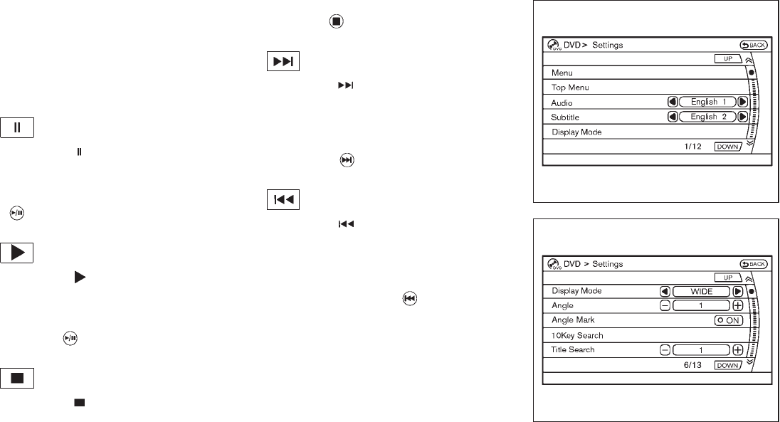
Black plate (238,1)
Model "Z51-D" EDITED: 2009/ 8/ 3
will turn off automatically after a period of time.
To turn it on again, push the “DISC” button once
more.
DVD operation keys
To operate the DVD drive, select the preferred
key displayed on the operation screen using the
multi-function controller.
PAUSE:
Select the “ ” key and push the ENTER
button to pause the DVD. To resume playing the
DVD, use the “PLAY” key.
To pause the DVD, it is also possible to push the
“” button on the keypad of the remote
controller.
PLAY:
Select the “ ” key and push the ENTER
button to start playing the DVD, for example,
after pausing the DVD.
To start playing the DVD, it is also possible to
push the “ ” button on the keypad of the
remote controller.
STOP:
Select the “ ” key and push the ENTER
button to stop playing the DVD.
To stop playing the DVD, it is also possible to
push the “ ” button on the keypad of the
remote controller.
SKIP (FORWARD):
Select the “ ” key and push the ENTER
button to skip the chapter(s) of the disc forward.
The chapters will advance the number of times
the ENTER button is pushed.
To skip the chapter(s) forward, it is also possible
to push the “ ” button on the keypad of the
remote controller.
SKIP (REWIND):
Select the “ ” key and push the ENTER
button to skip the chapter(s) of the disc back-
ward. The chapters will go back the number of
times the ENTER button is pushed.
To skip the chapter(s) backward, it is also
possible to push the “ ” button on the
keypad of the remote controller.
SAA2003
Setting (front) — DVD VIDEO-1
SAA1831
Setting (front) — DVD VIDEO-2
4-70 Monitor, heater, air conditioner, audio, phone and voice recognition systems

Black plate (239,1)
Model "Z51-D" EDITED: 2009/ 8/ 3
SAA2013
Setting (front) — DVD VIDEO-3
SAA2014
Setting (rear) — DVD VIDEO-1
SAA1194
Setting (rear) — DVD VIDEO-2
SAA1195
Setting (rear) — DVD VIDEO-3
DVD settings
Select the “Settings” key with the multi-
function controller and push the ENTER button
to adjust the following settings.
The items indicated with “*” can also be set from
the rear display. Push the “DVD” button on the
remote controller while a DVD is being played.
Select the preferred item using the joystick
“” on the remote controller and push the
ENTER “” button.
Menu* (DVD-VIDEO):
Some menus specific to each disc will be
shown. For details, see the instructions attached
to the disc.
Top Menu* (DVD-VIDEO):
Each title menu in the disc will be shown. For
details, see the instructions attached to the disc.
Audio* (DVD-VIDEO, VIDEO-CD) / Subtitle*
(DVD-VIDEO):
Choose the preferred language using the multi-
function controller and push the ENTER button.
To turn off the subtitle, push and hold the
ENTER button until a beep sounds.
Display Mode* (DVD-VIDEO, VIDEO-CD):
Choose from the “Full”, “Wide”, “Normal” or
“Cinema” mode using the multi-function con-
Monitor, heater, air conditioner, audio, phone and voice recognition systems 4-71
Black plate (240,1)
Model "Z51-D" EDITED: 2009/ 8/ 3
troller and push the ENTER button again.
Angle* (DVD-VIDEO):
If the DVD contains different angles (such as
moving images), the current image angle can be
switched to another one.
Select the “Angle” key and push the ENTER
button. When the “+” side or “−” side is
selected, the angle will change.
Angle Mark (DVD-VIDEO):
When this item is turned on, an angle mark will
be shown on the bottom of the screen if the
scene can be seen from a different angle.
10 Key Search* (DVD-VIDEO, VIDEO-CD,
CD-DA):
Select the “10 Key Search” key and push the
ENTER button to open the number entry screen.
Input the number you want to search for and
select the “OK” key with the multi-function
controller. Then push the ENTER button. The
specified Title/Chapter or Group/Track will be
played.
Title Search* (DVD-VIDEO):
The scene with the specified title will be
displayed the number of times the “+” side or
“−” side is selected.
Select No.* (VIDEO-CD):
Select the “Select No.” key and push the
ENTER button to open the number entry screen.
Input the number you wish to search for and
select the “OK” key with the multi-function
controller, and then push the ENTER button.
The specified scene will be played.
Menu Skip (DVD-VIDEO):
DVD menus are automatically configured and
the contents will be played directly when the
“Menu Skip” key is turned on. Note that some
discs may not be played directly even if this item
is turned on.
DVD Language (DVD-VIDEO, VIDEO-CD):
Select the “DVD Language” key and push the
ENTER button to open the number entry screen.
Input the number corresponding to the preferred
language and select the “OK” key with the multi-
function controller. Then push the ENTER
button. The DVD top menu language will be
changed to the one specified.
DRC (DVD-VIDEO):
DRC (Dynamic Range Compression) allows you
to tune the dynamic range of the sound
recorded in the Dolby Digital format.
Remote controller operation
Use the remote controller to adjust the following
items.
Rear display open/close:
To open or close the flip-down rear display, push
the “ ” button on the remote controller.
Joystick:
Use the joystick “ ” to select the items
displayed on the rear screen.
ENTER button:
Push the ENTER “” button to make the
selected item complete on the rear screen.
BACK button:
Press to go back to the previous screen or
cancel the selection.
Display tilt:
Adjust the display angle by pushing the “DIS-
PLAY TILT” button or .
DVD mode:
To select the DVD mode, push the DVD button.
AUX mode:
To select the AUX (Auxiliary input jacks) mode,
push the AUX button.
4-72 Monitor, heater, air conditioner, audio, phone and voice recognition systems

Black plate (241,1)
Model "Z51-D" EDITED: 2009/ 8/ 3
Volume:
To control the volume level, push the “VOL”
button or .
Display:
Press to adjust the rear display screen bright-
ness, tint, contrast, etc.
Aspect:
To change the display size, push the “ASPECT”
button. Each time the button is pushed, the
display size will change to “Cinema”, “Wide”,
“Full” or “Normal”.
Sound:
To change the language, push the “SOUND”
button. Each time the button is pushed, the
language will change to each language stored in
the DVD.
Headphones:
The DVD sound can be heard through the
headphones.
Push the “ ” button. Each time the button is
pushed the mode will switch to ON or OFF.
To control the volume of sound from the
headphones, use the VOLUME CONTROL
knob attached to the headphones.
Track/Channel:
Press to skip to the previous or next DVD scene
selection.
Keypad:
: PLAY/PAUSE button
: STOP button
: FORWARD button
: REWIND button
: FORWARD button for still images (for
DVD-AUDIO)
: REWIND button for still images (for DVD-
AUDIO)
CARE AND MAINTENANCE
Use a lightly dampened, lint free cloth to clean
the surfaces of your Mobile Entertainment
System. (DVD player face, screen, remote
controller, etc.)
CAUTION
.Do not use any solvents or cleaning
solutions when cleaning the video
system.
.Do not use excessive force on the
monitor screen.
.Avoid touching or scratching the
monitor screen as it may become
dirty or damaged.
.Do not attempt to operate the
system in extreme temperature con-
ditions [below −48F(−208C) and
above 1588F (708C)].
.Do not attempt to operate the
system in extreme humidity condi-
tions (less than 10% or more than
75%).
Monitor, heater, air conditioner, audio, phone and voice recognition systems 4-73
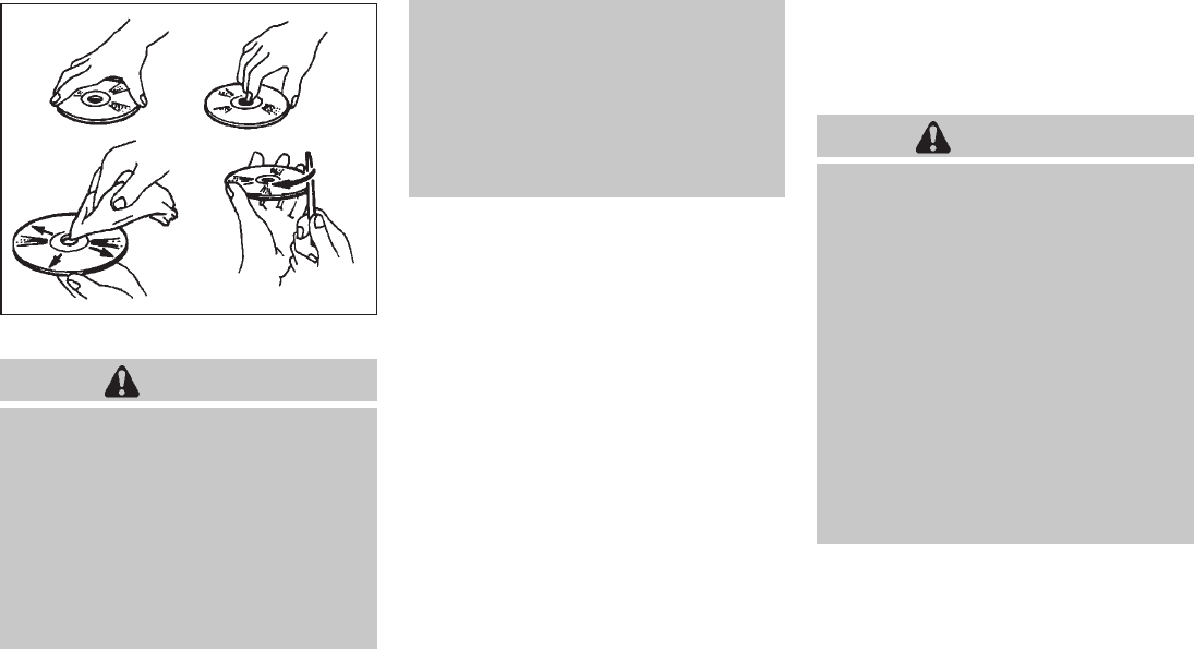
Black plate (242,1)
Model "Z51-D" EDITED: 2009/ 8/ 3
SAA0451
How to handle the DVD
CAUTION
.Handle a DVD by its edges. Never
touch the surface of the disc.
.To clean a disc, wipe the surface
from the center to the outer edge
using a clean, soft cloth. Do not
wipe the disc using a circular mo-
tion.
.Do not use a conventional record
cleaner, benzine, thinner or alcohol
intended for industrial use.
.A new disc may be rough on its
inner and outer edges. Remove the
rough edges using the side of a pen
or pencil as illustrated.
.Never attempt to use a DVD that has
been cracked, deformed, or repaired
using adhesive. Doing so may cause
damage to the equipment.
.Handle the DVD carefully to avoid contam-
ination or flaws. Otherwise, signals may not
be read properly.
.Do not write, draw or attach anything on any
side of the DVD.
.Do not store the DVD in locations with direct
sunlight or in high temperatures or humidity.
.Always place discs in the storage case
when they are not being used.
.Do not put on any sticker or write anything
on either surface of the DVD.
When installing a car phone or a CB radio in
your NISSAN, be sure to observe the following
cautions, otherwise the new equipment may
adversely affect the electronic control modules
and electronic control system harness.
WARNING
.A cellular telephone should not be
used while driving so full attention
may be given to vehicle operation.
Some jurisdictions prohibit the use
of cellular telephones while driving.
.If you must make a call while your
vehicle is in motion, the hands-free
cellular phone operational mode (if
so equipped) is highly recom-
mended. Exercise extreme caution
at all times so full attention may be
given to vehicle operation.
.If a conversation in a moving vehicle
requires you to take notes, pull off
the road to a safe location and stop
your vehicle before doing so.
CAR PHONE OR CB RADIO
4-74 Monitor, heater, air conditioner, audio, phone and voice recognition systems

Black plate (243,1)
Model "Z51-D" EDITED: 2009/ 8/ 3
CAUTION
.Keep the antenna as far away as
possible from the electronic control
modules.
.Keep the antenna wire more than 8
in (20 cm) away from the electronic
control system harness. Do not
route the antenna wire next to any
harness.
.Adjust the antenna standing-wave
ratio as recommended by the man-
ufacturer.
.Connect the ground wire from the
CB radio chassis to the body.
.For details, consult a NISSAN deal-
er.
WARNING
.Use a phone after stopping your
vehicle in a safe location. If you
have to use a phone while driving,
exercise extreme caution at all
times so full attention may be given
to vehicle operation.
.If you find yourself unable to devote
full attention to vehicle operation
while talking on the phone, pull off
the road to a safe location and stop
your vehicle before doing so.
CAUTION
To avoid draining the vehicle battery,
use a phone after starting the engine.
Your NISSAN is equipped with Bluetooth®
Hands-Free Phone System. If you are an owner
of a compatible Bluetooth®enabled cellular
phone, you can set up the wireless connection
between your cellular phone and the in-vehicle
phone module. With Bluetooth®wireless tech-
nology, you can make or receive a telephone call
with your cellular phone in your pocket.
Once your cellular phone is paired to the in-
vehicle phone module, no phone connecting
procedure is required anymore. Your phone is
automatically connected with the in-vehicle
phonemodulewhentheignitionswitchis
pushed to the ON position with the registered
cellular phone turned on and carried in the
vehicle.
You can register up to 5 different Bluetooth®
cellular phones in the in-vehicle phone module.
However, you can talk on only one cellular phone
at a time.
The NISSAN Voice Recognition system sup-
ports the phone commands, so dialing a phone
number using your voice is possible. For more
details, see “NISSAN VOICE RECOGNITION
SYSTEM (models with navigation system)” later
in this section; page 4-99.
Before using the Bluetooth®Hands-Free Phone
System, refer to the following notes.
.Set up the wireless connection between a
cellular phone and the in-vehicle phone
module before using the Bluetooth®
Hands-Free Phone System.
.Some Bluetooth®enabled cellular phones
may not be recognized by the in-vehicle
phone module. Please visit
www.nissanusa.com/bluetooth for a recom-
mended phone list.
.You will not be able to use a hands-free
phone under the following conditions:
BLUETOOTH®HANDS-FREE PHONE
SYSTEM WITH NAVIGATION
SYSTEM
Monitor, heater, air conditioner, audio, phone and voice recognition systems 4-75

Black plate (244,1)
Model "Z51-D" EDITED: 2009/ 8/ 3
— Your vehicle is outside of the telephone
service area.
— Your vehicle is in an area where it is
difficult to receive radio waves; such as in
a tunnel, in an underground parking
garage, behind a tall building or in a
mountainous area.
— Your cellular phone is locked in order not
to be dialed.
.When the radio wave condition is not ideal
or ambient sound is too loud, it may be
difficult to hear the other person’s voice
during a call.
.Immediatelyaftertheignitionswitchis
pushed to the ON position, it may be
impossible to receive a call for a short
period of time.
.Do not place the cellular phone in an area
surrounded by metal or far away from the in-
vehicle phone module to prevent tone quality
degradation and wireless connection dis-
ruption.
.While a cellular phone is connected through
the Bluetooth®wireless connection, the
battery power of the cellular phone may
discharge quicker than usual.
.If the Bluetooth®Hands-Free Phone System
seems to be malfunctioning, please visit
www.nissanusa.com/bluetooth for trouble-
shooting help.
.Some cellular phones or other devices may
cause interference or a buzzing noise to
come from the audio system speakers.
Storing the device in a different location
may reduce or eliminate the noise.
.Refer to the cellular phone Owner’s Manual
regarding the telephone pairing procedure
specific to your phone, battery charging,
cellular phone antenna, etc.
.The antenna display on the monitor will not
coincide with the antenna display of some
cellular phones.
.Keep the interior of the vehicle as quiet as
possible to hear the caller’s voice clearly as
well as to minimize its echoes.
.If reception between callers is unclear,
adjusting the incoming or outgoing call
volume may improve the clarity.
REGULATORY INFORMATION
FCC Regulatory information
— CAUTION: To maintain compliance with
FCC’s RF exposure guidelines, use only
the supplied antenna. Unauthorized antenna,
modification, or attachments could damage
the transmitter and may violate FCC regula-
tions.
— Operation is subject to the following two
conditions:
1) this device may not cause interference and
2) this device must accept any interference,
including interference that may cause un-
desired operation of the device
IC Regulatory information
— Operation is subject to the following two
conditions: (1) this device may not cause
interference, and (2) this device must accept
any interference, including interference that
may cause undesired operation of the
device.
— This Class B digital apparatus meets all
requirements of the Canadian Interference-
Causing Equipment Regulations.
Bluetooth trademark:
BLUETOOTH®is a trademark
owned by Bluetooth SIG, Inc.,
U.S.A.
VOICE COMMANDS
You can use voice commands to operate various
Bluetooth®Hands-Free Phone System features
using the NISSAN Voice Recognition system.
For more details, see “NISSAN VOICE RE-
COGNITION SYSTEM (models with navigation
4-76 Monitor, heater, air conditioner, audio, phone and voice recognition systems

Black plate (245,1)
Model "Z51-D" EDITED: 2009/ 8/ 3
system)” later in this section; page 4-99.
SAA1857
CONTROL BUTTONS
1) PHONE button
2) TALK/PHONE SEND button
SAA1895
PAIRING PROCEDURE
1. Push the PHONE button or the button,
and select the “Pair phone” key on the
display using the multi-function controller.
Then push the ENTER button.
Monitor, heater, air conditioner, audio, phone and voice recognition systems 4-77

Black plate (246,1)
Model "Z51-D" EDITED: 2009/ 8/ 3
SAA1572
2. Select the “None (Add New)” key from the
name list of the phones, and push the
ENTER button.
SAA1925
3. When a PIN code appears on the screen,
operate the Bluetooth®cellular phone to
enter the PIN code.
The pairing procedure of the cellular phone
varies according to each cellular phone. See
the cellular phone Owner’s Manual for the
details. You can also visit
www.nissanusa.com/bluetooth or call
NISSAN Consumer Affairs Department for
instructions on pairing NISSAN recom-
mended cellular phones.
When the pairing is completed, the screen
will return to the Bluetooth®setup display.
SAA1574
PHONEBOOK REGISTRATION
Up to 40 phone numbers can be stored in the
phonebook.
1. Push the SETTING button, and select the
“PHONE” key on the display using the multi-
function controller. Then push the ENTER
button.
2. Select the “Phonebook” key, and push the
ENTER button.
3. Select the “None (Add New)” key from the
name list of the phonebook, and push the
ENTER button.
4-78 Monitor, heater, air conditioner, audio, phone and voice recognition systems

Black plate (247,1)
Model "Z51-D" EDITED: 2009/ 8/ 3
SAA1575
4. Select the “Transfer via Bluetooth” key, and
push the ENTER button in order to register
your cellular phone memory in the phone-
book.
5. Operate the cellular phone to send a
person’s name and phone number from the
memory of the cellular phone. The memory
sending procedure from the cellular phone
varies according to each cellular phone
manufacturer. See the cellular phone Own-
er’s Manual for more details.
SAA1576
6. After the memory is registered in the phone-
book, the system will ask if you want to add
a voicetag for it. If you want to add a
voicetag, select the “YES” key on the “Add a
voicetag?” screen. For example, if the
partner’s name is David, speak “David” after
a tone. The “David” voicetag is stored in the
phonebook. Voicetags allow easy dialing
using the NISSAN Voice Recognition sys-
tem. (See “NISSAN VOICE RECOGNITION
SYSTEM (models with navigation system)”
later in this section; page 4-99.)
7. When the phonebook registration is com-
pleted, the screen will return to the name list
of the phonebook.
.To confirm the stored voicetags, select
the “Voicetag Directory” key using the
multi-function controller, and push the
ENTER button.
.There are different methods to input a
phone number. Select one of the follow-
ing options instead of “Transfer via
Bluetooth” in step 4 above.
—Enter Data by Keypad
Input the name and phone number manually
using the keypad displayed on the screen.
(See “HOW TO USE TOUCH SCREEN
(models with navigation system)” earlier in
this section.)
—Copy from Downloaded Phonebook
Copy a phonebook from the Bluetooth®
cellular phone. The availability of this func-
tion depends on each cellular phone. The
copying procedure from the cellular phone
also varies according to each cellular phone.
See cellular phone Owner’s Manual for more
details.
—Copy from Outgoing Call Logs
Store the name and phone number from the
outgoing call list.
—Copy from Incoming Call Logs
Store the name and phone number from the
Monitor, heater, air conditioner, audio, phone and voice recognition systems 4-79

Black plate (248,1)
Model "Z51-D" EDITED: 2009/ 8/ 3
incoming call list.
—Delete
Delete a contact that is registered in the
phonebook.
SAA1895
MAKING A CALL
To make a call, follow the procedures below.
1. Push the PHONE button on the instrument
panel or the button on the steering
wheel. The “PHONE” screen will appear on
the display.
2. Select the “Call (Phonebook)” key on the
“PHONE” menu, and push the ENTER
button.
3. Select the registered person’s name from
the list, and push the ENTER button. Dialing
will start and the screen will change to the
call-in-progress screen.
4. After the call is over, perform one of the
following to finish the call.
a. Select the “Hang up” key and push the
ENTER button.
b. Push the button on the steering
wheel.
c. Push the PHONE button on the instru-
ment panel.
There are different methods to make a call.
Select one of the following options instead of
“Call (Phonebook)” in step 2 above.
.Redial
Dial the previously dialed number again.
.Call (Call Logs)
Select the name or phone number from the
incoming or outgoing call logs.
.Call (Downloaded)
Select the name or phone number from the
downloaded call list.
.Dial (Keypad)
Input the phone number manually using the
keypad displayed on the screen. (See
“HOW TO USE TOUCH SCREEN (models
with navigation system)” earlier in this
section.)
4-80 Monitor, heater, air conditioner, audio, phone and voice recognition systems

Black plate (249,1)
Model "Z51-D" EDITED: 2009/ 8/ 3
SAA1578
RECEIVING A CALL
When you hear a phone ring, the display will
change to the incoming call mode. To receive a
call, perform one of the following procedures
listed below.
a) Select the “Answer” key on the display and
push the ENTER button.
b) Push the PHONE button on the instrument
panel.
c) Push the button on the steering wheel.
There are some options available when receiving
a call. Select one of the following displayed on
the screen.
.Answer
Accept an incoming call to talk.
.On Hold
Put an incoming call on hold.
.Reject Call
Reject an incoming call.
To finish the call, perform one of the
following procedures listed below.
a) Select the “Hang up” key on the display and
push the ENTER button.
b) Push the PHONE button on the instrument
panel.
c) Push the button on the steering wheel.
SAA1579
DURING A CALL
There are some options available during a call.
Select one of the following displayed on the
screen if necessary.
.Hang up
Finish the call.
.Use Handset
Transfer the call to the cellular phone.
.Mute
Mute your voice to the person.
Monitor, heater, air conditioner, audio, phone and voice recognition systems 4-81

Black plate (250,1)
Model "Z51-D" EDITED: 2009/ 8/ 3
.Keypad
Send a dial tone to the caller for using
network services such as voice mail.
.Cancel Mute
This will appear after “Mute” is selected.
Mute will be canceled.
To adjust the person’s voice to be louder or
quieter, push the volume control switch (+ or −)
on the steering wheel or turn the volume control
knob on the instrument panel while talking on
the phone. This adjustment is also available in
the SETTING mode. SAA1580
PHONE SETTING
To set up the Bluetooth®Hands-Free Phone
System to your preferred settings, push the
SETTING button on the instrument panel and
select the “PHONE” key on the display, and then
push the ENTER button.
Phonebook
See “PHONEBOOK REGISTRATION” earlier in
this section for adding, editing and deleting a
contact.
SAA1581
Downloaded Phonebook
Refer to the following information for each item.
.Download All
Download all of the contacts registered in
the Bluetooth®cellular phone. Availability of
this function depends on each cellular
phone. The memory downloading procedure
from the cellular phone also varies according
to each cellular phone. See cellular phone
Owner’s Manual for more details.
.Delete Downloaded Phonebook
Delete a downloaded phonebook.
4-82 Monitor, heater, air conditioner, audio, phone and voice recognition systems
Black plate (251,1)
Model "Z51-D" EDITED: 2009/ 8/ 3
.Delete an Entry of Downloaded Phone-
book
Delete an entry from the downloaded
phonebook.
Automatic Hold
If this item is turned on, an incoming call will be
placed on hold automatically after several rings.
Use Vehicle Ringtone
If this item is turned on, a specific ringtone that is
different from the cellular phone’s will sound
when receiving a call.
Delete Call Logs
Delete all of the incoming or outgoing call logs
from the list.
Bluetooth Setup
See the following information for each item.
.Bluetooth
If this setting is turned off, the connection
between the cellular phone and the in-
vehicle phone module will be canceled.
.Bluetooth Info
Check information about the device name,
device PIN and connection status.
.Pair Phone
See “PAIRING PROCEDURE” later in this
section.
.Priority Change
Use this command to change the priority
level of the active phone.
The priority level determines which phone
will be connected to the system when more
than one paired Bluetooth®phone is in the
vehicle.
The system states the priority level of the
active phone and asks for a new priority level
(1, 2, 3, 4, 5).
If the new priority level is already being used
for another phone, the two phones will swap
priority levels.
For example, if the current priority levels are:
Priority Level 1 = Phone A
Priority Level 2 = Phone B
Priority Level 3 = Phone C
and you change the priority level of Phone C
to Level 1, then:
Priority Level 1 = Phone C
Priority Level 2 = Phone B
Priority Level 3 = Phone A
.Remove Paired Phone
Delete a registered cellular phone from the
paired list.
.Paired Phone List
Up to 5 registered cellular phones are
shown on the list. If you select a cellular
phone that is different from the one currently
being connected, the newly selected phone
will be connected to the system.
.Edit Phone Name
Rename the registered cellular phones using
the keypad displayed on the screen. (See
“HOW TO USE TOUCH SCREEN (models
with navigation system)” earlier in this
section.)
Monitor, heater, air conditioner, audio, phone and voice recognition systems 4-83

Black plate (252,1)
Model "Z51-D" EDITED: 2009/ 8/ 3
TROUBLESHOOTING GUIDE
The system should respond correctly to all voice commands without difficulty. If problems are encountered, try the following solutions.
Where the solutions are listed by number, try each solution in turn, starting with number 1, until the problem is resolved.
Symptom Solution
System fails to interpret the command
correctly.
1. Ensure that the command is valid. (See “NISSAN VOICE RECOGNITION SYSTEM (models with navigation system)” later in
this section; page 4-99.)
2. Ensure that the command is spoken after the tone.
3. Speak clearly without pausing between words and at a level appropriate to the ambient noise level in the vehicle.
4. Ensure that the ambient noise level is not excessive (for example, windows open or defroster on). NOTE: If it is too noisy to
use the phone, it is likely that the voice commands will not be recognized.
5. If more than one command was said at a time, try saying the commands separately.
The system consistently selects the
wrong voicetag.
1. Ensure that the voicetag requested matches what was originally stored. (See “PHONEBOOK REGISTRATION” earlier in this
section.)
2. Replace one of the names being confused with a new name.
4-84 Monitor, heater, air conditioner, audio, phone and voice recognition systems

Black plate (253,1)
Model "Z51-D" EDITED: 2009/ 8/ 3
WARNING
.Use a phone after stopping your
vehicle in a safe location. If you
have to use a phone while driving,
exercise extreme caution at all
times so full attention may be given
to vehicle operation.
.If you find yourself unable to devote
full attention to vehicle operation
while talking on the phone, pull off
the road to a safe location and stop
your vehicle before doing so.
CAUTION
To avoid draining the vehicle battery,
use a phone after starting the engine.
Your NISSAN is equipped with Bluetooth®
Hands-Free Phone System. If you are an owner
of a compatible Bluetooth®enabled cellular
phone, you can set up the wireless connection
between your cellular phone and the in-vehicle
phone module. With Bluetooth®wireless tech-
nology, you can make or receive a telephone call
with your cellular phone in your pocket.
Once your cellular phone is paired to the in-
vehicle phone module, no phone connecting
procedure is required anymore. Your phone is
automatically connected with the in-vehicle
phonemodulewhentheignitionswitchis
pushed to the ON position with the registered
cellular phone turned on and carried in the
vehicle.
You can register up to 5 different Bluetooth®
cellular phones in the in-vehicle phone module.
However, you can talk on only one cellular phone
at a time.
The NISSAN Voice Recognition system sup-
ports the phone commands, so dialing a phone
number using your voice is possible.
Before using the Bluetooth®Hands-Free Phone
System, refer to the following notes.
.Set up the wireless connection between a
compatible cellular phone and the in-vehicle
phone module before using the Bluetooth®
Hands-Free Phone System.
.Some Bluetooth®enabled cellular phones
may not be recognized by the in-vehicle
phone module. Please visit
www.nissanusa.com/bluetooth for a recom-
mended phone list.
.You will not be able to use a hands-free
phone under the following conditions:
— Your vehicle is outside of the telephone
service area.
— Your vehicle is in an area where it is
difficult to receive radio waves; such as in
a tunnel, in an underground parking
garage, behind a tall building or in a
mountainous area.
— Your cellular phone is locked in order not
to be dialed.
.When the radio wave condition is not ideal
or ambient sound is too loud, it may be
difficult to hear the other person’s voice
during a call.
.Immediately after the ignition switch is
pushed to the ON position, it may be
impossible to receive a call for a short
period of time.
.Do not place the cellular phone in an area
surrounded by metal or far away from the in-
vehicle phone module to prevent tone quality
degradation and wireless connection dis-
ruption.
.While a cellular phone is connected through
the Bluetooth®wireless connection, the
battery power of the cellular phone may
discharge quicker than usual.
.If the Bluetooth®Hands-Free Phone System
seems to be malfunctioning, please visit
www.nissanusa.com/bluetooth for trouble-
shooting help.
BLUETOOTH®HANDS-FREE PHONE
SYSTEM WITHOUT NAVIGATION
SYSTEM (if so equipped)
Monitor, heater, air conditioner, audio, phone and voice recognition systems 4-85

Black plate (254,1)
Model "Z51-D" EDITED: 2009/ 8/ 3
.Some cellular phones or other devices may
cause interference or a buzzing noise to
come from the audio system speakers.
Storing the device in a different location
may reduce or eliminate the noise.
.Refer to the cellular phone Owner’s Manual
regarding the telephone pairing procedure
specific to your phone, battery charging,
cellular phone antenna, etc.
.The antenna display on the monitor will not
coincide with the antenna display of some
cellular phones.
.Keep the interior of the vehicle as quiet as
possible to hear the caller’s voice clearly as
well as to minimize its echoes.
.If reception between callers is unclear,
adjusting the incoming or outgoing call
volume may improve the clarity.
REGULATORY INFORMATION
FCC Regulatory information
— CAUTION: To maintain compliance with
FCC’s RF exposure guidelines, use only
the supplied antenna. Unauthorized antenna,
modification, or attachments could damage
the transmitter and may violate FCC regula-
tions.
— Operation is subject to the following two
conditions:
1) this device may not cause interference and
2) this device must accept any interference,
including interference that may cause un-
desired operation of the device
IC Regulatory information
— Operation is subject to the following two
conditions: (1) this device may not cause
interference, and (2) this device must accept
any interference, including interference that
may cause undesired operation of the
device.
— This Class B digital apparatus meets all
requirements of the Canadian Interference-
Causing Equipment Regulations.
Bluetooth trademark:
BLUETOOTH®is a trademark
owned by Bluetooth SIG, Inc.,
U.S.A.
INITIALIZATION
When the ignition switch is pushed to the ON
position, NISSAN Voice Recognition is initia-
lized, which takes a few seconds. If the
button is pushed before the initialization com-
pletes, the system will announce “Hands-free
phone system not ready” and will not react to
voice commands.
OPERATING TIPS
To get the best performance out of the NISSAN
Voice Recognition system, observe the follow-
ing:
.Keep the interior of the vehicle as quiet as
possible. Close the windows to eliminate
surrounding noises (traffic noises, vibration
sounds, etc.), which may prevent the system
from recognizing voice commands correctly.
.Wait until the tone sounds before speaking a
command. Otherwise, the command will not
be received properly.
.Start speaking a command within 5 seconds
after the tone sounds.
.Speak in a natural voice without pausing
between words.
GIVING VOICE COMMANDS
To operate NISSAN Voice Recognition, push
and release the button located on the
steering wheel. After the tone sounds, speak a
command.
Thecommandgivenispickedupbythe
microphone, and voice feedback is given when
the command is accepted.
.If you need to hear the available commands
for the current menu again, say “Help” and
the system will repeat them.
4-86 Monitor, heater, air conditioner, audio, phone and voice recognition systems

Black plate (255,1)
Model "Z51-D" EDITED: 2009/ 8/ 3
.If a command is not recognized, the system
announces, “Command not recognized.
Please try again.” Repeat the command in
a clear voice.
.If you want to go back to the previous
command, you can say “Go back” or
“Correction” any time the system is waiting
for a response.
.You can cancel a command when the
system is waiting for a response by saying,
“Cancel” or “Quit.” The system announces
“Cancel” and ends the voice recognition
(VR) session. You can also push the
button on the steering wheel at any time.
Whenever the VR session is canceled, a
double beep is played to indicate you have
exited the system.
.If you want to adjust the volume of the voice
feedback, push the volume control switches
(+ or −) on the steering wheel while being
provided with feedback. You can also use
the radio volume control knob.
NOTE:
The voice command “Help” is available at
any time. Please say “Help” to obtain the
information about how to use the NISSAN
Voice Recognition system.
How to say numbers
NISSAN Voice Recognition requires a certain
way to speak numbers in voice commands.
Refer to the rules and examples below.
.Either “zero” or “oh” can be used for “0”.
Example: 1-800-662-6200
—“One eight oh oh six six two six two oh
oh”, or
—“One eight zero zero six six two six two oh
oh”
.Words can be used for the first 4 digits
places only.
Example: 1-800-662-6200
—“One eight hundred six six two six two oh
oh”,
—NOT “One eight hundred six six two sixty
two hundred, and
—NOT “One eight oh oh six six two sixty two
hundred.
.Numbers can be spoken in small groups.
The system will prompt you to continuing
entering digits, if desired.
Example: 1-800-662-6200
—“One eight zero zero”
The system repeats the numbers and
prompts you to enter more.
—“six six two”
The system repeats the numbers and
prompts you to enter more.
—“six two zero zero”
.You can say “Star” for * and “Pound” for # at
anytime in any position of the phone number.
(Available only when using the “Call Inter-
national” command.)
Example: 1-555-1212 *123
—“One five five five one two one two star
one two three”
NOTE:
For best results, say phone numbers as
single digits.
Monitor, heater, air conditioner, audio, phone and voice recognition systems 4-87

Black plate (256,1)
Model "Z51-D" EDITED: 2009/ 8/ 3
SAA1858
CONTROL BUTTONS
The control buttons for the Bluetooth®Hands-
Free Phone System are located on the steering
wheel.
TALK/PHONE SEND
Push the button to initiate a VR session
or answer an incoming call.
You can also use the button to skip
through system feedback and to enter
commands during a call. (See “LIST OF
VOICE COMMANDS” later in this section
and “DURING A CALL” earlier in this section
for more information.)
PHONE END
Push the button to cancel a VR session
or end a call.
GETTING STARTED
The following procedures will help you get
started using the Bluetooth®Hands-Free Phone
System with NISSAN Voice Recognition. For
additional command options, see “LIST OF
VOICE COMMANDS” later in this section.
CHOOSING A LANGUAGE
You can interact with the Bluetooth®Hands-Free
Phone System using English, Spanish or French.
See “HOW TO USE SETTING BUTTON” earlier
in this section to change the language.
PAIRING PROCEDURE
1. Push the button on the steering wheel.
The system announces the available com-
mands.
2. Say: “Setup” *
A. The system acknowl-
edges the command and announces the
next set of available commands.
3. Say: “Pair phone” *
B. The system acknowl-
edges the command and announces the
next set of available commands.
4. Say: “New phone” *
C. The system ac-
knowledges the command and asks you to
initiate pairing from the phone handset *
D.
When you are asked to enter a Pass Key for
pairing your Bluetooth®cellular phone,
operate it to enter the code “1234”.
The code is always “1234” regardless of the
number of phones paired.
The pairing procedure of the cellular phone
varies according to each cellular phone. See
the cellular phone Owner’s Manual for
details. You can also visit
www.nissanusa.com/bluetooth for instruc-
tions on pairing NISSAN recommended
cellular phones.
5. The system asks you to say a name for the
phone *
E.
If the name is too long or too short, the
4-88 Monitor, heater, air conditioner, audio, phone and voice recognition systems
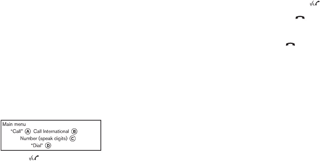
Black plate (257,1)
Model "Z51-D" EDITED: 2009/ 8/ 3
system tells you, then prompts you for a
name again.
Also, if more than one phone is paired and
the name sounds too much like a name
already used, the system tells you, then
prompts you for a name again.
6. The system asks you to assign a priority level
*
F. The priority level determines which
phone is active when more than one paired
Bluetooth®phone is in the vehicle. Follow
the instructions provided by the system or
see “SETUP” later in this section for more
information on changing priorities.
7. The system will ask if you would like to
select a custom ringtone *
G. Follow the
instructions provided by the system or see
“SETUP” later in this section for more
information on selecting ringtones.
MAKING A CALL BY ENTERING A
PHONE NUMBER
1. Push the button on steering wheel. A
tone will sound.
2. Say: “Call” *
A. The system acknowledges
the command and announces the next set of
available commands.
Say: “Call International” *
Bto dial more
than 10 digits using any special characters.
3. Say the number you wish to call, starting
with the area code in the single digit format
*
C. For better recognition results, it is
recommended to say the numbers in small
groups like, the 3-digits area code, the next
3 digits, then the last 4 digits. For example,
555-121-3354 can be said as “five five five”
(1st group), “one two one” (2nd group) and
“three three five four” (3rd group). (See
“How to say numbers” earlier in this section
for more information.)
4. When you have finished speaking the phone
number, the system repeats it back and
announces the available commands.
5. Say: “Dial” *
D. The system acknowledges
the command and makes the call.
For additional command options, see “LIST OF
VOICE COMMANDS” later in this section.
RECEIVING A CALL
When you hear the ringtone, press the
button on the steering wheel.
Once the call has ended, press the button
on the steering wheel.
NOTE:
If you do not wish to take the call when you
hear the ringtone, press the button on
the steering wheel to reject the call.
For additional command options, see “LIST OF
VOICE COMMANDS” later in this section.
Monitor, heater, air conditioner, audio, phone and voice recognition systems 4-89
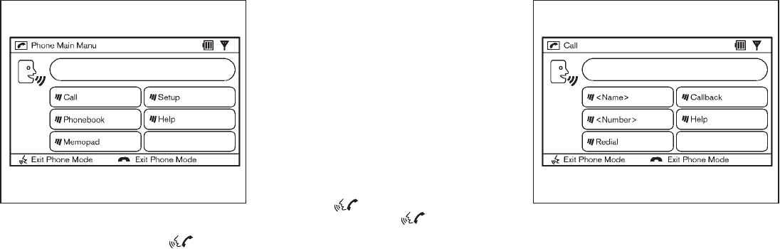
Black plate (258,1)
Model "Z51-D" EDITED: 2009/ 8/ 3
SAA1926
LIST OF VOICE COMMANDS
When you push and release the button on
the steering wheel, you can choose from the
commands on the Main Menu. The following
pages describe these commands and the
commands in each sub-menu.
Remember to wait for the tone before
speaking.
You can say “Help” to hear the list of commands
currently available any time the system is waiting
for a response.
If you want to end an action without completing
it, you can say “Cancel” or “Quit” at any time
while the system is waiting for a response. The
system will end the VR session. Whenever the
VR session is canceled, a double beep is played
to indicate you have exited the system.
If you want to go back to the previous command,
you can say “Go back” or “Correction” anytime
the system is waiting for a response.
When you get used to the menus in the system,
you can talk ahead by saying more than one
command at a time. For example, say, “Call five
five five one two one two” or “Memo pad
record.”
Also, when you get used to the system
responses, you can skip ahead to the tone by
pressing the button on the steering wheel.
However, if you press the button when the
system is waiting for a response from you it will
end the VR session.
SAA1927
CALL
<Name> (speak name)
If you have stored entries in the Phone Book, you
can dial a number associated with a name and
location.
See “PHONE BOOK” later in this section to
learn how to store entries.
When prompted by the system, say the name of
the phone book entry (voicetag) you wish to call.
The system acknowledges the name.
If there are multiple locations associated with
the name, the system asks you to choose the
location.
4-90 Monitor, heater, air conditioner, audio, phone and voice recognition systems

Black plate (259,1)
Model "Z51-D" EDITED: 2009/ 8/ 3
Onceyouhaveconfirmedthenameand
location, the system begins the call.
<Number> (speak digits)
When prompted by the system, say the number
you wish to call. (See “How to say numbers”
earlier in this section and “MAKING A CALL BY
ENTERING A PHONE NUMBER” earlier in this
section for more details.)
“Redial”
Use the Redial command to call the last number
that was dialed within the vehicle.
NOTE:
The system will not redial the last number
dialed by the handset keypad.
The system acknowledges the command, re-
peats the number and begins dialing.
If a redial number does not exist, the system
announces, “There is no number to redial” and
ends the VR session.
“Callback”
Use the Call Back command to dial the number
of the last incoming call within the vehicle.
The system acknowledges the command, re-
peats the number and begins dialing. If a call
back number does not exist, the system
announces, “There is no number to call back”
and ends the VR session.
International
For dialing more than 10 digits or any special
characters, please say “Call International”.
When the system acknowledges the command,
the system will prompt you to speak the number.
During a call
During a call there are several command options
available. Press the button on the steering
wheel to mute the receiving voice and enter
commands.
.“Help” — The system announces the avail-
able commands.
.“Go back/Correction” — The system an-
nounces “Go back,” ends the VR session
and returns to the call.
.“Cancel/Quit” — The system announces
“Cancel,” ends the VR session and returns
to the call.
.“Send/Enter/Call/Dial” — Use the Send
command to enter numbers during a call.
For example, if you were directed to dial an
extension by an automated system:
Say: “Send one two three four.”
The system acknowledges the command
and sends the tones associated with the
numbers. The system then ends the VR
session and returns to the call.
.“Transfer Call” — Use the Transfer Call
command to transfer the call from the
Bluetooth®Hands-Free Phone System to
the cellular phone when privacy is desired.
The system announces, “Transfer call. Call
transferred to privacy mode.” The system
then ends the VR session.
You can also issue the Transfer Call
command again to return to a hands-free
call through the vehicle.
.“Mute” — Use the Mute command to mute
your voice so the other party cannot hear it.
Use the mute command again to unmute
your voice.
NOTE:
If the other party ends the call or the
cellular phone network connection is lost
while the Mute feature is on, the Mute
feature may need to be reset to “off.”
Monitor, heater, air conditioner, audio, phone and voice recognition systems 4-91

Black plate (260,1)
Model "Z51-D" EDITED: 2009/ 8/ 3
SAA1928
PHONE BOOK
The Phone Book stores up to 40 names for each
phone paired with the system. Each name can
have up to 4 locations/phone numbers asso-
ciated with it.
NOTE:
Each phone has its own separate phone
book. You cannot access Phone A’s phone
book if you are currently connected with
Phone B.
“New Entry”
Use the New Entry command to store a new
name in the system.
When prompted by the system, say the name
you would like to give the new entry (voicetag).
For example, say: “Mary.”
If the name is too long or too short, the system
tells you, then prompts you for a name again.
Also, if the name sounds too much like a name
already stored, the system tells you, then
prompts you for a name again.
Once the system accepts the name and you
confirm it is correct, the system asks for a
location (Home, Office, Mobile or Other).
For example, say: “Home.”
The system acknowledges the location.
The system will ask you to say a phone number
or to transfer a phone number stored in the
cellular phone’s memory.
To enter a phone number by voice command:
For example, say: “five five five one two one
two.” (See “How to say numbers” earlier in this
section for more information.)
To transfer a phone number stored in the cellular
phone’s memory (if so equipped):
Say “Transfer entry.” The system acknowledges
the command and asks you to initiate the
transfer from the phone handset. The new
contact phone number will be transferred from
the cellular phone via the Bluetooth®commu-
nication link.
The transfer procedure varies according to each
cellular phone. See the cellular phone Owner’s
Manual for details. You can also visit
www.nissanusa.com/bluetooth for instructions
on transferring phone numbers from NISSAN
recommended cellular phones.
The system repeats the number and prompts
you for the next command. When you have
finished entering numbers, choose “Store.”
The system confirms the name, location and
number. The system then asks if you would like
to store another location for the same name. If
you do not wish to store another location, the
system ends the VR session.
“Edit”
Use the Edit command to alter an existing phone
book entry or to add a 2nd, 3rd or 4th phone
number to an existing entry.
When prompted by the system, say the name of
the entry you wish to edit.
The system acknowledges the name and asks
you for the location you would like to edit.
Say the name of the location.
The system acknowledges the location.
4-92 Monitor, heater, air conditioner, audio, phone and voice recognition systems

Black plate (261,1)
Model "Z51-D" EDITED: 2009/ 8/ 3
The system will ask you to say a phone number
or to transfer a phone number stored in the
cellular phone’s memory.
To enter a phone number by voice command:
For example, say: “five five five one two one
two.” (See “How to say numbers” earlier in this
section for more information.)
To transfer a phone number stored in the cellular
phone’s memory (if so equipped):
Say “Transfer entry.” The system acknowledges
the command and asks you to initiate the
transfer from the phone handset. The new
contact phone number will be transferred from
the cellular phone via the Bluetooth®commu-
nication link.
The transfer procedure varies according to each
cellular phone. See the cellular phone Owner’s
Manual for details. You can also visit
www.nissanusa.com/bluetooth for instructions
on transferring phone numbers from NISSAN
recommended cellular phones.
The system repeats the number and prompts
you for the next command. When you have
finished entering numbers, choose “Store.”
The system confirms the name, location and
number, then announces that the entry has been
stored. The system then ends the VR session.
“Delete”
Use the Delete command to erase one entry
from the phone book, all entries from the phone
book, the current redial number or the current
call back number.
To delete entries from the phone book, say a
name or “All entries” when prompted by the
system.
The system acknowledges the command and
asks you to confirm the deletion.
To delete the current redial number or call back
number, say “redial number” or “call back
number” when prompted by the system.
If a redial number or a call back number exists,
the system deletes them without asking for
confirmation.
If there is no number for the entry you are trying
to delete, the system says so and ends the VR
session.
“List Names”
Use the List Names command to hear all the
names and locations in the phone book.
The system recites the phone book entries but
does not include the actual phone numbers.
When the playback of the list is complete the
system ends the VR session.
You can stop the playback of the list at any time
by pressing the button on the steering
wheel. The system ends the VR session.
Monitor, heater, air conditioner, audio, phone and voice recognition systems 4-93

Black plate (262,1)
Model "Z51-D" EDITED: 2009/ 8/ 3
SAA1929
MEMO PAD
The Memo Pad records a maximum of 6 voice
memos, each up to 20 seconds long.
“Play”
The system plays back all the memos in the
order of newest to oldest. The system ends the
VR session.
If there are no memos recorded, the system
announces “No messages to play.” The system
ends the VR session.
“Record”
The system announces “Recording” and a tone
sounds signaling you to begin.
Speak the information you wish to record clearly.
When you are done, press the or
button on the steering wheel.
A tone sounds and the system announces
“Memo recorded.” Another tone sounds to end
the VR session.
If the memo pad is full, the system asks if you
wish to record over the oldest memo.
“Delete”
The Delete command erases all memos. The
system asks you to confirm this action before
deleting all memos. SAA1930
SETUP
Use the Setup command to change options
associated with the Bluetooth®Hands-Free
Phone System.
“Pair Phone”
Use the Pair Phone command to pair a phone to
the Bluetooth®Hands-Free Phone System.
When you are asked to enter a PIN code for
pairing your Bluetooth®cellular phone, operate it
to enter the code “1234”.
The code is always “1234” regardless of the
number of phones paired.
4-94 Monitor, heater, air conditioner, audio, phone and voice recognition systems
Black plate (263,1)
Model "Z51-D" EDITED: 2009/ 8/ 3
Up to 5 phones can be paired. If you try to pair a
sixth phone, the system announces that you
must first delete one phone or replace an
existing phone.
If you try to pair a phone that has already been
paired to your vehicle’s system, the system
announces the name the phone is already using.
The pairing procedure will then be canceled.
When prompted by the system, choose from the
following commands:
.“New phone” — see “PAIRING PROCE-
DURE” earlier in this section.
.“Replace phone” — The system announces
the names of the phones already paired and
asks which you would like to replace.
Once you say the name of the phone you
wish to replace, the paring procedure will
begin. (See “PAIRING PROCEDURE” ear-
lier in this section.)
.“List phone” — See the description below.
“List Phones”
Use the List Phone command to hear the names
of the phones currently paired. If no phones are
paired, the system announces, “No paired
phones to list.” The system then ends the VR
session.
“Select Phone”
Use the Select Phone command to select a
phone of lesser priority when two or more
phones paired with Bluetooth®Hands-Free
Phone System are in the vehicle at the same
time.
The system asks you to name the phone and
confirm the selection.
Once the selection is confirmed, the selected
phone remains active until the ignition switch is
pushed to the LOCK position or you select a
new phone.
“Change Priority”
Use the Change Priority command to change
the priority level of the active phone.
The priority level determines which phone is
active when more than one paired Bluetooth®
phone is in the vehicle.
The system states the priority level of the active
phone and asks for a new priority level (1, 2, 3,
4, 5).
If the new priority level is already being used for
another phone, the two phones will swap priority
levels.
For example, if the current priority levels are:
Priority Level 1 = Phone A
Priority Level 2 = Phone B
Priority Level 3 = Phone C
and you change the priority level of Phone C to
Level 1, then:
Priority Level 1 = Phone C
Priority Level 2 = Phone B
Priority Level 3 = Phone A
“Delete Phone”
Use the Delete Phone command to delete a
specific phone or all phones from the Bluetooth®
Hands-Free Phone System.
The system announces the names of the phones
already paired with the system and their priority
level. The system then gives you the option to
delete a specific phone, all phones or listen to
the list again.
Once you choose to delete a phone or all
phones, the system asks you to confirm this
action.
NOTE:
When you delete a phone, the associated
phone book for that phone will also be
deleted.
Monitor, heater, air conditioner, audio, phone and voice recognition systems 4-95

Black plate (264,1)
Model "Z51-D" EDITED: 2009/ 8/ 3
“Select Ring tone”
Use the Select Ring tone command to select the
tone heard in the vehicle when an incoming call
is received.
The system announces the name of the active
phoneandasksyoutochoosefromthe
following commands:
.“Ringtone” — The system plays a ringtone
and asks if you would like to select that tone.
If you say no, the system plays the next
ringtone available and continues to cycle
through the ringtones until you select one or
quit.
.“Silent” — The system asks you to confirm
your wish to disable the ringtone.
SPEAKER ADAPTATION (SA) MODE
Speaker Adaptation allows up to two out-of
dialect users to train the system to improve
recognition accuracy. By repeating a number of
commands, the users can create a voice model
of their own voice that is stored in the system.
The system is capable of storing a different
speaker adaptation model for memory A and
memory B.
If memory A is available, the system will use
memory A to store the model. If memory A is in
use and memory B is available, the system will
use memory B to store the model. If both of the
memory locations are in use, the system will ask
the user to select which memory location should
be overwritten.
Training procedure
The procedure for training a voice is as follows.
1. Position the vehicle in a reasonably quiet
outdoor location.
2. Sit in the driver’s seat with the engine
running, the parking brake on, and the
transmission in the P (Park) position.
3. Press and hold the button for more
than 5 seconds.
4. The system announces: “Press the PHONE/
SEND ( ) button for the hands-free
phone system to enter the speaker adapta-
tion mode”.
5. Press the button.
6. Voice memory A or memory B is selected
automatically. If both memory locations are
already in use, the system will prompt you to
overwrite one. Follow the instructions pro-
vided by the system.
7. When preparation is complete and you are
ready to begin, the press the button.
8. The SA mode will be explained. Follow the
instructions provided by the system.
9. When training is finished, the system will tell
you an adequate number of phrases have
been recorded.
10. The system will ask you to say your name.
Follow the instructions to register your
name.
11. The system will announce that speaker
adaptation has been completed and the
system is ready.
The SA mode will stop if:
.The button is pressed for more than 5
seconds in SA mode.
.The vehicle is driven during SA mode.
.The ignition switch is pushed to the OFF or
LOCK position.
Training phrases
During the SA mode, the system instructs you to
say the following phrases.
(The system will prompt you for each phrase.)
.phone book new entry
.dial three oh four two nine
.delete call back number
.setup pair phone
.memo pad play
4-96 Monitor, heater, air conditioner, audio, phone and voice recognition systems
Black plate (265,1)
Model "Z51-D" EDITED: 2009/ 8/ 3
.eight pause nine three two pause seven
.delete all entries
.call seven two four zero nine
.phone book delete entry
.memo pad record
.dial star two one seven oh
.Yes
.No
.select ringtone
.dial eight five six nine two
.Bluetooth on
.setup change priority
.call three one nine oh two
.nine seven pause pause three oh eight
.Cancel
.call back number
.call star two zero nine five
.delete phone
.dial eight three zero five one
.Home
.four three pause two nine pause zero
.delete redial number
.phone book list names
.call eight oh five four one
.Correction
.setup change ringtone
.dial seven four oh one eight
.setup main menu
.Delete
.dial nine seven two six six
.memo pad delete
.call seven six three oh one
.go back
.call five six two eight zero
.dial six six four three seven
Monitor, heater, air conditioner, audio, phone and voice recognition systems 4-97
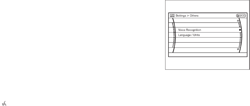
Black plate (267,1)
Model "Z51-D" EDITED: 2009/ 8/ 3
NISSAN Voice Recognition allows hands-free
operation of the systems equipped on this
vehicle in one of two modes, Standard Mode
or Alternate Command Mode.
In Standard Mode, commands that are available
are always shown on the display and announced
by the system. You can complete your desired
operation by simply following the prompts given
by the system. (See “NISSAN VOICE RECOG-
NITION STANDARD MODE” later in this section
for details.) In this mode, hands-free operation of
Audio, Air Conditioner and Display is not
available through NISSAN Voice Recognition.
For advanced operation, you can use the
Alternate Command Mode that enables the
operation of the display, audio, and air condi-
tioner through NISSAN Voice Recognition. (See
“NISSAN VOICE RECOGNITION ALTERNATE
COMMAND MODE” later in this section for
details.) When this mode is active, an expanded
list of commands can be spoken after pushing
the TALK switch, and the voice command
menu prompts are turned off. Note that in this
mode the recognition success rate may be
affected as the number of available commands
and the ways of speaking each command are
increased.
For U.S. customers, the Standard Mode is
selected by default. For Canadian customers,
the Alternate Command Mode is the default
mode. To switch one mode to another, see each
mode description later in this section.
To improve the recognition success rate when
Alternate Command Mode is active, try using the
Speaker Adaptation Function available in that
mode. Otherwise, it is recommended that
Alternate Command Mode be turned off and
Standard Mode be used for the best recognition
performance.
For the voice commands for the navigation
system, refer to the Navigation System Owner’s
Manual of your vehicle.
NISSAN VOICE RECOGNITION
STANDARD MODE
The following section is applicable when the
Standard Mode is activated. (This mode is
selected by default for U.S. customers.)
The Standard Mode enables you to complete
the desired operation by simply following the
prompts that appear on the display and also are
announced by the system. Hands-free operation
of Audio, Air Conditioner and Display systems is
not available in this mode.
SAA1566
Activating Standard Mode
When the Alternate Command Mode is active,
perform the following steps to switch to the
Standard Mode.
1. Push the SETTING button on the instrument
panel.
2. Highlight the “Others” key on the display
and then push the ENTER button.
3. Highlight the “Voice Recognition” key and
then push the ENTER button.
NISSAN VOICE RECOGNITION
SYSTEM (models with navigation
system)
Monitor, heater, air conditioner, audio, phone and voice recognition systems 4-99
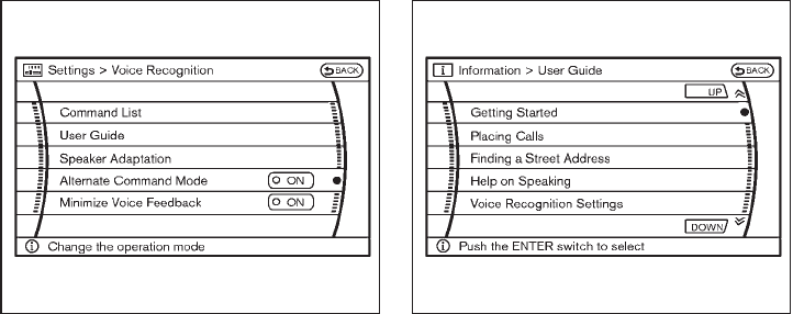
Black plate (268,1)
Model "Z51-D" EDITED: 2009/ 8/ 3
SAA1917
4. Highlight the “Alternate Command Mode”
key and push the ENTER button.
5. The indicator turns off and the Standard
Mode activates.
Displaying user guide
IfyouusetheNISSANVoiceRecognition
system for the first time or you do not know
how to operate it, you can display the User
Guide for confirmation.
You can confirm how to use voice commands by
accessing a simplified User Guide, which
contains basic instructions and tutorials for
several voice commands.
SAA2164
1. Push the INFO button on the instrument
panel.
2. Highlight the “Voice Recognition” key using
the NISSAN controller and push the ENTER
button.
3. Highlight the “User Guide” key using the
NISSAN controller and push the ENTER
button.
4. Highlight an item using the NISSAN con-
troller and push the ENTER button.
You can skip steps 1 and 2 above if you say
“Help”.
Available items:
.Getting Started
Describes the basics of how to operate the
NISSAN Voice Recognition system.
.Placing Calls
Tutorial for making a phone call by voice
command operation.
.Finding a Street Address
Tutorial for entering a destination by street
address.
.Help on Speaking
Displays useful tips of speaking for correct
command recognition by the system.
.Voice Recognition Settings
Describes the available voice recognition
settings.
Note that the Command List feature is only
available when Alternate Command Mode is
active.
4-100 Monitor, heater, air conditioner, audio, phone and voice recognition systems

Black plate (269,1)
Model "Z51-D" EDITED: 2009/ 8/ 3
SAA1904
Getting Started
Before using the NISSAN Voice Recognition
system for the first time, you can confirm how to
use commands by viewing the Getting Started
section of the User Guide.
1. Highlight “Getting Started” and push the
ENTER button.
2. You can confirm the page by scrolling the
screen using the NISSAN controller.
Tutorials on the operation of the NISSAN
Voice Recognition system
If you choose “Finding a Street Address” or
“Placing Calls”, you can view tutorials on how to
perform these operations using NISSAN Voice
Recognition.
SAA2165
Useful tips for correct operation
You can display useful speaking tips to help the
system recognize your voice commands cor-
rectly.
Highlight “Help on Speaking” and push the
ENTER button.
Monitor, heater, air conditioner, audio, phone and voice recognition systems 4-101

Black plate (271,1)
Model "Z51-D" EDITED: 2009/ 8/ 3
SAA1908
2. A list of commands appears on the screen,
and the system announces, “Would you like
to access Phone, Navigation, Information or
Help?”.
3. After the tone sounds and the icon on the
screen changes from to , speak a
command.
4. Continue to follow the voice menu prompts
and speak after the tone sounds until your
desired operation is completed.
Operating tips:
.Say a command after the tone.
.Commands that are available are always
shown on the display and spoken through
voice menu prompts. Commands other than
those that are displayed are not accepted.
Please follow the prompts given by the
system.
.If the command is not recognized, the
system announces, “Please say again”.
Repeat the command in a clear voice.
.Push the BACK button once to return to the
previous screen.
.If you want to cancel the command, push
and hold the TALK switch. The
message, “Voice cancelled” will be an-
nounced.
.Push the TALK switch to pause the
operation. Push the TALK switch again
to restart the operation.
.If you want to adjust the volume of the
system feedback, push the volume control
buttons [+] or [−] on the steering switch or
use the audio system volume knob while the
system is making an announcement.
How to speak numbers:
NISSAN Voice Recognition requires a certain
way to speak numbers when giving voice
commands. Refer to the following examples.
General rule
Only single digits 0 (zero) to 9 can be used. (For
example, if you would like to say 500, “five zero
zero” can be used, but “five hundred” cannot.)
Examples
.1-800-662-6200
— “One eight zero zero six six two six two
zero zero”
Improving Recognition of Phone numbers
You can improve the recognition of phone
numbers by saying the phone number in three
groups of numbers. For example, when you try to
call 800-662-6200, say “eight zero zero” first,
and the system will then ask you for the next
three digits. Then, say “six six two”. After
recognition, the system will then ask for the last
four digits. Say, “six two zero zero”. Using this
method of phone digit entry can improve
recognition performance.
When speaking a house number, speak the
number “0” as “zero”. If the letter “o (Oh)” is
included in the house number, it will not be
recognized as the number “0 (zero)” even if you
speak “oh” instead of “zero”. You can only say
“zero” for “0 (zero)”.
Monitor, heater, air conditioner, audio, phone and voice recognition systems 4-103
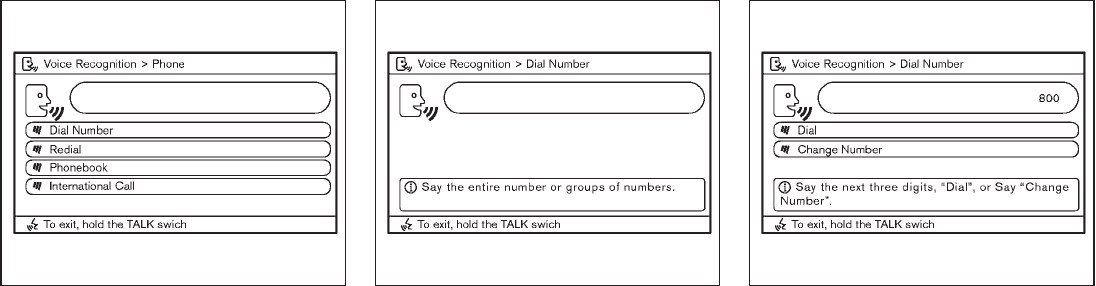
Black plate (274,1)
Model "Z51-D" EDITED: 2009/ 8/ 3
SAA1909
4. Speak “Dial Number”.
SAA1910
5. Speak “8 0 0”.
SAA1911
6. The system announces, “Please say the next
three digits or dial, or say change number.”
7. Speak “6 6 2”.
4-106 Monitor, heater, air conditioner, audio, phone and voice recognition systems

Black plate (275,1)
Model "Z51-D" EDITED: 2009/ 8/ 3
SAA1912
8. The system announces, “Please say the last
four digits” or say change number.
9. Speak “6 2 0 0”.
SAA1913
10. The system announces, “Dial or Change
Number?”
11. Speak “Dial”.
12. The system makes a call to 800-662-6200.
Note:
.You can also speak “800-662-6200” (10
continuous digits) or “662-6200” (7 con-
tinuous digits), if the area code is not
necessary. However, the 3-3-4 digit group-
ing is recommended for improved recogni-
tion. (See “How to speak numbers” earlier in
this section.)
.You can only say a phone number using the
3-3-4 grouping, 7 digits, and 10 digits using
this command. Please use the “International
Call” command for all other formats.
.If you say “Change Number” during phone
number entry, the system will automatically
request that you repeat the number using
the 3-3-4 format. In this case please say the
area code first and then follow the prompts.
.Do not add a “1” in front of the area code
when speaking phone numbers.
.If the system does not recognize your
command, please try repeating the com-
mand using a natural voice. Speaking too
slow or too loudly may further decrease
recognition performance.
Monitor, heater, air conditioner, audio, phone and voice recognition systems 4-107
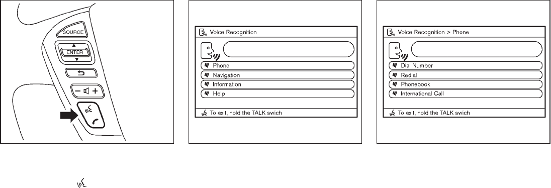
Black plate (276,1)
Model "Z51-D" EDITED: 2009/ 8/ 3
SAA1859
Example 2 - Placing an international call to
the phone number 011-81-111-222-3333:
1. Push the TALK switch located on the
steering wheel.
SAA1908
2. The system announces, “Would you like to
access Phone, Navigation, Information or
Help?”
3. Speak “Phone”.
SAA1909
4. Speak “International Call”.
4-108 Monitor, heater, air conditioner, audio, phone and voice recognition systems

Black plate (277,1)
Model "Z51-D" EDITED: 2009/ 8/ 3
SAA1914
5. Speak “01181111222333”.
SAA1915
6. Speak “Dial”.
7. System makes a call to 011-81-111-222-
3333.
Note:
Any digit input format is available in the
International Number input process.
NISSAN VOICE RECOGNITION AL-
TERNATE COMMAND MODE
The following section is applicable when Alter-
nate Command Mode is activated. (This mode is
selected by default for Canadian customers.)
The Alternate Command Mode enables the
operation of the display, audio, and air condi-
tioner through Voice Recognition. When this
mode is active, an expanded list of commands
can be spoken after pushing the TALK
switch, and the voice command menu prompts
are turned off.
Please note that in this mode the recognition
success rate may be affected as the number of
available commands and ways of speaking each
command are increased. To improve the recog-
nition success rate, try using the Speaker
Adaptation Function available in that mode.
(See “Speaker adaptation function (for Alternate
Command Mode)” later in this section.)
In the Alternate Command Mode, review the
expanded command list for this mode, as some
commands available in the Standard Mode are
replaced. Please see the examples on the
screen.
Monitor, heater, air conditioner, audio, phone and voice recognition systems 4-109

Black plate (278,1)
Model "Z51-D" EDITED: 2009/ 8/ 3
SAA1566
Activating Alternate Command Mode
When the Standard Mode is active, perform the
following steps to switch to the Alternate
Command Mode.
1. Push the SETTING button on the instrument
panel.
2. Highlight the “Others” key on the display
and then push the ENTER button.
3. Highlight the “Voice Recognition” key and
then push the ENTER button.
SAA2168
4. Highlight the “Alternate Command Mode”
key and push the ENTER button.
5. The confirmation message is displayed on
the screen. Push the “OK” key to activate
the Alternate Command Mode.
Displaying command list
If you are controlling the system by voice
commands for the first time or do not know the
appropriate voice command, perform the follow-
ing procedure for displaying the voice command
list (available only in Alternate Command Mode).
SAA1545
1. Push the INFO button on the instrument
panel.
2. Highlight the “Voice Recognition” key using
the NISSAN controller and push the ENTER
button.
3. Highlight the “Command List” key using the
NISSAN controller and push the ENTER
button.
You can skip steps 1 and 2 above if you say
“Help”.
4-110 Monitor, heater, air conditioner, audio, phone and voice recognition systems

Black plate (280,1)
Model "Z51-D" EDITED: 2009/ 8/ 3
List of help commands
Navigation Commands:
See the separate Navigation System Owner’s Manual.
Phone Commands:
COMMAND ACTION
Redial Redials the phone number last dialed.
Dial Number Dials the phone number given in the command.
Phonebook Shows the first page of the “Phonebook” list.
Outgoing Calls Shows the outgoing call history (1 to 5).
Incoming Calls Shows the incoming call history (1 to 5).
International Call Makes an international call by allowing more than 10 digits to be spoken.
Audio Commands:
.Music Box
COMMAND ACTION
Music Box Turns on the “Music Box” hard-disk drive audio system.
.Radio
COMMAND ACTION
Radio Turns the radio on, selecting the station and band last played.
Radio AM Turns to the AM band, selecting the station last played.
Radio FM Turns to the FM band, selecting the station last played.
4-112 Monitor, heater, air conditioner, audio, phone and voice recognition systems

Black plate (281,1)
Model "Z51-D" EDITED: 2009/ 8/ 3
.Satellite
COMMAND ACTION
Satellite Radio Turns the SAT radio on, selecting the station and band last played.
.CD
COMMAND ACTION
CD Starts to play a CD.
.Audio
COMMAND ACTION
Audio OFF Turns the audio system off.
.iPod®
COMMAND ACTION
iPod®Turns the iPod®system on.
Vehicle Information Commands:
COMMAND ACTION
Traffic Info. Turns the traffic information system ON and OFF.
Fuel Economy Displays the Fuel Economy screen.
Maintenance Displays the Maintenance screen.
Monitor, heater, air conditioner, audio, phone and voice recognition systems 4-113

Black plate (282,1)
Model "Z51-D" EDITED: 2009/ 8/ 3
Climate Commands:
COMMAND ACTION
Climate Control Turns the climate control system on and operates it in the AUTO mode.
Climate Control OFF Turns the climate control system off.
4-114 Monitor, heater, air conditioner, audio, phone and voice recognition systems
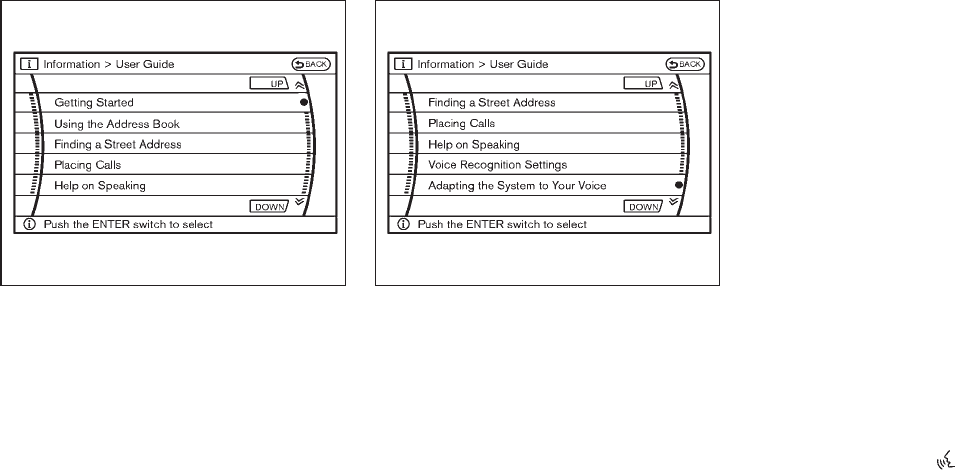
Black plate (283,1)
Model "Z51-D" EDITED: 2009/ 8/ 3
SAA1783
Displaying user guide
You can confirm how to use voice commands by
accessing a simplified User Guide, which
contains basic instructions and tutorials for
several voice commands.
1. Push the INFO button on the instrument
panel.
2. Highlight the “Voice Recognition” key using
the NISSAN controller and push the ENTER
button.
3. Highlight the “User Guide” key using the
NISSAN controller and push the ENTER
button.
SAA2170
4. Highlight an item using the NISSAN con-
troller and push the ENTER button.
Available items:
.Getting Started
Describe the basics of how to operate the
NISSAN Voice Recognition system.
.Using the Address Book
Refer to Navigation System Owner’s Man-
ual.
.Finding a Street Address (if so equipped)
Refer to Navigation System Owner’s Man-
ual.
.Placing Calls
Tutorial for making a phone call by voice
command operation.
.Help on Speaking
Displays useful tips for how to correctly
speak commands in order for them to be
properly recognized by the system.
.Voice Recognition Settings
Describes the available voice recognition
settings.
.Adapting the System to Your Voice.
Tutorial adapting the system to your voice.
USING THE SYSTEM
Initialization
When the ignition switch is pushed to the ON
position, NISSAN Voice Recognition is initia-
lized, which takes a few seconds. When
completed, the system is ready to accept voice
commands. If the TALK switch is pushed
before the initialization completes the display will
show the message: “Phonetic data downloaded.
Please wait.” or a beep sounds.
Before starting
To get the best performance from NISSAN
Voice Recognition, observe the following:
Monitor, heater, air conditioner, audio, phone and voice recognition systems 4-115
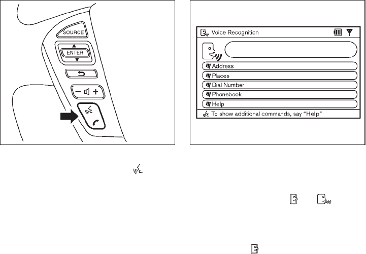
Black plate (284,1)
Model "Z51-D" EDITED: 2009/ 8/ 3
.Keep the interior of the vehicle as quiet as
possible. Close the windows to eliminate the
surrounding noises (traffic noises, vibration
sounds, etc.), which may prevent the system
from recognizing the voice commands cor-
rectly.
.When the air conditioner is in the AUTO
mode, the fan speed decreases automati-
cally for easy recognition.
.Wait until a tone sounds before speaking a
command.
.Speak in a natural voice without pausing
between words. SAA1859
Giving voice command
1. Push and release the TALK switch
located on the steering wheel.
SAA1932
2. A list of commands appears on the screen,
and the system announces, “Please say a
command”.
3. After the tone sounds and the icon on the
screen changes from to , speak a
command.
Operating tips:
.Voice commands cannot be accepted when
the icon is .
.The list displayed can be scrolled by tilting
the ENTER switch on the steering wheel.
.If the command is not recognized, the
system announces, “Please say again”.
4-116 Monitor, heater, air conditioner, audio, phone and voice recognition systems

Black plate (285,1)
Model "Z51-D" EDITED: 2009/ 8/ 3
Repeat the command in a clear voice.
.Push the BACK button once to return to the
previous screen.
.If you want to cancel the command, push
and hold the TALK switch for 1 second.
The message “Voice canceled” will be
announced.
.Push the TALK switch again to pause
the operation. Push the TALK switch to
restart the operation.
.If you want to adjust the volume of the
system feedback, push the volume control
buttons (+ or −) on the steering wheel or
use the audio system volume knob while the
system is making an announcement.
How to speak numbers:
NISSAN Voice Recognition requires a certain
way to speak numbers when giving voice
commands. Refer to the following examples.
General rule
Only single digits 0 (zero) to 9 can be used. (For
example, if you would like to say 500, “five zero
zero” can be used, but “five hundred” cannot.)
Phone numbers
Speak phone numbers according to the follow-
ing examples:
.1-800-662-6200
— “Dial one eight zero zero six six two zero
zero.”
Note 1: For the best voice recognition phone
dialing results, say phone numbers as single
digits.
Note 2: You cannot say 555-6000 as “five five
five six thousands”.
Note 3: When speaking a house number, speak
the number “0” as “zero”. If the letter “o (Oh)” is
included in the house number, it will not be
recognized as the number “0 (zero)” even if you
speak “oh” instead of “zero”. You can only say
“zero” for “0 (Zero)”.
SAA1907
Speaker adaptation function (for Alter-
nate Command Mode)
The voice recognition system has a function to
learn the user’s voice for better voice recognition
performance. The system can memorize the
voices of up to three persons.
Having the system learn the user’s voice:
1. Push the SETTING button on the instrument
panel, highlight the “Others” key on the
display and then push the ENTER button.
Monitor, heater, air conditioner, audio, phone and voice recognition systems 4-117

Black plate (287,1)
Model "Z51-D" EDITED: 2009/ 8/ 3
6. Select a voice command and then push the
ENTER button.
The voice recognition system starts.
SAA1921
7. The system requests that you repeat a
command after a tone.
8. After the tone sounds and the icon on the
screen changes from to , speak
the command that the system requested.
9. When the system has recognized the voice
command, the voice of the user is learned.
Push the switch or BACK button to return
to the previous screen.
If the system has learned the command cor-
rectly, the voice command indicator on the
screen turns on.
SAA1922
Speaker Adaptation function settings:
Edit Name
Edit the user name using the keypad displayed
on the screen.
Store Result
When this item is turned to ON, the voice
recognition system can easily recognize the
user’s voice that it has learned.
Reset Result
Resets the user’s voice that the voice recogni-
tion system has learned.
Monitor, heater, air conditioner, audio, phone and voice recognition systems 4-119
Black plate (288,1)
Model "Z51-D" EDITED: 2009/ 8/ 3
Continuous Learning
When this item is turned to ON, you can have
the system learn the voice commands in
succession, without selecting commands one
by one.
Minimize voice feedback (for Alternate
Command Mode)
To minimize the voice feedback from the system,
perform the following steps.
1. Push the SETTING button on the instrument
panel.
2. Highlight the “Others” key using the
NISSAN controller and push the ENTER
button.
3. Highlight the “Voice Recognition” key and
then push the ENTER button.
4. Highlight the “Minimize Voice Feedback” key
and push the ENTER button.
5. The item is turned to ON and the vocal
feedback is reduced if the voice recognition
system is activated.
4-120 Monitor, heater, air conditioner, audio, phone and voice recognition systems
Black plate (290,1)
Model "Z51-D" EDITED: 2009/ 8/ 3
MEMO
4-122 Monitor, heater, air conditioner, audio, phone and voice recognition systems

Black plate (16,1)
5 Starting and driving
Model "Z51-D" EDITED: 2009/ 10/ 26
Precautions when starting and driving ..................... 5-2
Exhaust gas (carbon monoxide) ......................... 5-2
Three-way catalyst.......................................... 5-2
Tire Pressure Monitoring System (TPMS)............. 5-3
Avoiding collision and rollover ........................... 5-5
On-pavement and off-road driving precautions ...... 5-5
Off-road recovery........................................... 5-6
Rapid air pressure loss.................................... 5-6
Drinking alcohol/drugs and driving...................... 5-7
Driving safety precautions ................................ 5-7
Push-button ignition switch .................................. 5-9
Intelligent Key system...................................... 5-9
Push-button ignition switch operation................ 5-10
Steering lock (if so equipped) ......................... 5-10
Push-button ignition switch positions ................ 5-11
Key port..................................................... 5-11
Intelligent Key battery discharge ...................... 5-12
Before starting the engine .................................. 5-12
Starting the engine ........................................... 5-13
Driving the vehicle ............................................ 5-13
Continuously Variable Transmission (CVT) .......... 5-13
Parking brake .................................................. 5-17
Cruise control ................................................. 5-18
Precautions on cruise control .......................... 5-18
Cruise control operations ............................... 5-18
Break-in schedule ............................................ 5-20
Increasing fuel economy .................................... 5-20
All-Wheel Drive (AWD) (if so equipped) ................ 5-21
All-Wheel Drive (AWD) lock switch operations.... 5-21
AWD warning light ....................................... 5-22
Parking/parking on hills...................................... 5-24
Power steering ................................................ 5-25
Brake system .................................................. 5-25
Braking precautions ...................................... 5-25
Parking brake break-in................................... 5-25
Anti-lock Braking System (ABS) ...................... 5-26
Vehicle Dynamic Control (VDC) system ................. 5-27
Cold weather driving......................................... 5-29
Freeing a frozen door lock.............................. 5-29
Anti-freeze.................................................. 5-29
Battery ...................................................... 5-29
Draining of coolant water ............................... 5-29
Tire equipment ............................................ 5-29
Special winter equipment ............................... 5-29
Driving on snow or ice .................................. 5-29
Engine block heater (if so equipped)................. 5-30

Black plate (292,1)
Model "Z51-D" EDITED: 2009/ 8/ 3
WARNING
.Do not leave children or adults who
would normally require the support
of others alone in your vehicle. Pets
should not be left alone either. They
could accidentally injure themselves
or others through inadvertent op-
eration of the vehicle. Also, on hot,
sunny days, temperatures in a
closed vehicle could quickly become
high enough to cause severe or
possibly fatal injuries to people or
animals.
.Properly secure all cargo with ropes
or straps to help prevent it from
sliding or shifting. Do not place
cargo higher than the seatbacks. In
a sudden stop or collision, unse-
cured cargo could cause personal
injury.
EXHAUST GAS (carbon monoxide)
WARNING
.Do not breathe exhaust gases; they
contain colorless and odorless car-
bon monoxide. Carbon monoxide is
dangerous. It can cause uncon-
sciousness or death.
.If you suspect that exhaust fumes
are entering the vehicle, drive with
all windows fully open, and have the
vehicle inspected immediately.
.Do not run the engine in closed
spaces such as a garage.
.Do not park the vehicle with the
engine running for any extended
length of time.
.Keep the lift gate closed while
driving, otherwise exhaust gases
could be drawn into the passenger
compartment. If you must drive with
the lift gate open, follow these
precautions:
1. Open all the windows.
2. Set the air recirculation to off
and the fan control to high to
circulate the air.
.If electrical wiring or other cable
connections must pass to a trailer
through the seal on the lift gate or
the body, follow the manufacturer’s
recommendation to prevent carbon
monoxide entry into the vehicle.
.If a special body, camper or other
equipment is added for recreational
or other usage, follow the manufac-
turer’s recommendation to prevent
carbon monoxide entry into the
vehicle. (Some recreational vehicle
appliances such as stoves, refrig-
erators, heaters, etc. may also gen-
erate carbon monoxide.)
.The exhaust system and body
should be inspected by a qualified
mechanic whenever:
— The vehicle is raised for service.
— You suspect that exhaust fumes
are entering into the passenger
compartment.
— You notice a change in the
sound of the exhaust system.
— You have had an accident invol-
ving damage to the exhaust
system, underbody, or rear of
the vehicle.
THREE-WAY CATALYST
The three-way catalyst is an emission control
device installed in the exhaust system. Exhaust
gases in the three-way catalyst are burned at
high temperatures to help reduce pollutants.
PRECAUTIONS WHEN STARTING
AND DRIVING
5-2 Starting and driving

Black plate (294,1)
Model "Z51-D" EDITED: 2009/ 8/ 3
alternate tires and wheels allow the TPMS to
continue to function properly.
Additional information
.The TPMS does not monitor the tire
pressure of the spare tire.
.The TPMS will activate only when the
vehicle is driven at speeds above 16 MPH
(25 km/h). Also, this system may not detect
a sudden drop in tire pressure (for example a
flat tire while driving).
.The low tire pressure warning light does not
automatically turn off when the tire pressure
is adjusted. After the tire is inflated to the
recommended pressure, the vehicle must be
driven at speeds above 16 MPH (25 km/h)
to activate the TPMS and turn off the low tire
pressure warning light. Use a tire pressure
gauge to check the tire pressure.
.Tire pressure rises and falls depending on
the heat caused by the vehicle’s operation
and the outside temperature. Low outside
temperature can lower the temperature of
the air inside the tire which can cause a
lower tire inflation pressure. This may cause
the low tire pressure warning light to
illuminate. If the warning light illuminates in
low ambient temperature, check the tire
pressure for all four tires.
For additional information, see “Low tire pres-
sure warning light” in the “2. Instruments and
controls” section and “TIRE PRESSURE MON-
ITORING SYSTEM (TPMS)” in the “6. In case of
emergency” section.
WARNING
.If the low tire pressure warning light
illuminates while driving, avoid sud-
den steering maneuvers or abrupt
braking, reduce vehicle speed, pull
off the road to a safe location and
stop the vehicle as soon as possi-
ble. Driving with under-inflated tires
may permanently damage the tires
and increase the likelihood of tire
failure. Serious vehicle damage
could occur and may lead to an
accident and could result in serious
personal injury. Check the tire pres-
sure for all four tires. Adjust the tire
pressure to the recommended COLD
tire pressure shown on the Tire and
Loading Information label to turn
the low tire pressure warning light
OFF. If the light still illuminates
while driving after adjusting the tire
pressure, a tire may be flat. If you
have a flat tire, replace it with a
spare tire as soon as possible. (See
“FLAT TIRE” in the “6. In case of
emergency” section for changing a
flat tire.)
.When a spare tire is mounted or a
wheel is replaced, the TPMS will not
function and the low tire pressure
warning light will flash for approxi-
mately 1 minute. The light will
remain on after 1 minute. Contact
your NISSAN dealer as soon as
possible for tire replacement and/
or system resetting.
.Replacing tires with those not ori-
ginally specified by NISSAN could
affect the proper operation of the
TPMS.
.Do not inject any tire liquid or
aerosol tire sealant into the tires,
as this may cause a malfunction of
the tire pressure sensors.
CAUTION
.The TPMS may not function properly
when the wheels are equipped with
tire chains or the wheels are buried
in snow.
.Do not place metalized film or any
5-4 Starting and driving

Black plate (295,1)
Model "Z51-D" EDITED: 2009/ 8/ 3
metal parts (antenna, etc.) on the
windows. This may cause poor re-
ception of the signals from the tire
pressure sensors, and the TPMS will
not function properly.
Some devices and transmitters may temporarily
interfere with the operation of the TPMS and
cause the low tire pressure warning light to
illuminate. Some examples are:
.Facilities or electric devices using similar
radio frequencies are near the vehicle.
.If a transmitter set to similar frequencies is
being used in or near the vehicle.
.If a computer (or similar equipment) or a DC/
AC converter is being used in or near the
vehicle.
FCC Notice:
Changes or modifications not expressly
approved by the party responsible for
compliance could void the user’s authority
to operate the equipment.
This device complies with Part 15 of the
FCC Rules and RSS-210 of Industry Cana-
da.
Operation is subject to the following two
conditions: (1) This device may not cause
harmful interference, and (2) this device
must accept any interference received,
including interference that may cause un-
desired operation of the device.
AVOIDING COLLISION AND ROLL-
OVER
WARNING
Failure to operate this vehicle in a safe
and prudent manner may result in loss
of control or an accident.
Be alert and drive defensively at all times. Obey
all traffic regulations. Avoid excessive speed,
high speed cornering, or sudden steering
maneuvers, because these driving practices
could cause you to lose control of your vehicle.
As with any vehicle, a loss of control could
result in a collision with other vehicles or
objects, or cause the vehicle to rollover,
particularly if the loss of control causes the
vehicle to slide sideways. Be attentive at all
times, and avoid driving when tired. Never drive
when under the influence of alcohol or drugs
(including prescription or over-the-counter
drugs which may cause drowsiness). Always
wear your seat belt as outlined in the “SEAT
BELTS” in the “1. Safety — Seats, seat belts and
supplemental restraint system” section of this
manual, and also instruct your passengers to do
so.
Seat belts help reduce the risk of injury in
collisions and rollovers. In a rollover crash, an
unbelted or improperly belted person is
significantly more likely to be injured or
killed than a person properly wearing a
seat belt.
ON-PAVEMENT AND OFF-ROAD
DRIVING PRECAUTIONS
Utility vehicles have a significantly higher
rollover rate than other types of vehicles.
They have higher ground clearance than pas-
senger cars to make them capable of performing
in a variety of on-pavement and off-road
applications. This gives them a higher center of
gravity than ordinary cars. An advantage of
higher ground clearance is a better view of the
road, allowing you to anticipate problems.
However, they are not designed for cornering
at the same speeds as conventional passenger
cars any more than low-slung sports cars are
designed to perform satisfactorily under off-road
conditions. If at all possible, avoid sharp turns or
abrupt maneuvers, particularly at high speeds.
As with other vehicles of this type, failure to
operate this vehicle correctly may result in loss
of control or vehicle rollover. Seat belts help
reduce the risk of injury in collisions and
rollovers. In a rollover crash, an unbelted or
improperly belted person is significantly more
Starting and driving 5-5

Black plate (297,1)
Model "Z51-D" EDITED: 2009/ 8/ 3
6. Turn on the hazard warning flashers and
either contact a roadside emergency service
to change the tire or see “CHANGING A
FLAT TIRE” in the “6. In case of emergency”
section of this Owner’s Manual.
DRINKING ALCOHOL/DRUGS AND
DRIVING
WARNING
Never drive under the influence of
alcohol or drugs. Alcohol in the blood-
stream reduces coordination, delays
reaction time and impairs judgement.
Driving after drinking alcohol increases
the likelihood of being involved in an
accident injuring yourself and others.
Additionally, if you are injured in an
accident, alcohol can increase the se-
verity of the injury.
NISSAN is committed to safe driving. However,
you must choose not to drive under the influence
of alcohol. Every year thousands of people are
injured or killed in alcohol-related accidents.
Although the local laws vary on what is
considered to be legally intoxicated, the fact is
that alcohol affects all people differently and
most people underestimate the effects of
alcohol.
Remember, drinking and driving don’t mix! And
that is true for drugs, too (over-the-counter,
prescription, and illegal drugs). Don’t drive if
your ability to operate your vehicle is impaired by
alcohol, drugs, or some other physical condition.
DRIVING SAFETY PRECAUTIONS
Your NISSAN is designed for both normal and
off-road use. However, avoid driving in deep
water or mud as your NISSAN is mainly
designed for leisure use, unlike a conventional
off-road vehicle.
Remember that Two-Wheel Drive (2WD) mod-
els are less capable than All-Wheel Drive
(AWD) models for rough road driving and
extrication when stuck in deep snow, mud, or
the like.
Please observe the following precautions:
WARNING
.Drive carefully when off the road
and avoid dangerous areas. Every
person who drives or rides in this
vehicle should be seated with their
seat belt fastened. This will keep
you and your passengers in position
when driving over rough terrain.
.Do not drive across steep slopes.
Instead drive either straight up or
straight down the slopes. Off-road
vehicles can tip over sideways much
more easily than they can forward or
backward.
.Many hills are too steep for any
vehicle. If you drive up them, you
may stall. If you drive down them,
you may not be able to control your
speed. If you drive across them, you
may roll over.
.Do not shift ranges while driving on
downhill grades as this could cause
loss of control of the vehicle.
.Stay alert when driving to the top of
a hill. At the top there could be a
drop-off or other hazard that could
cause an accident.
.If your engine stalls or you cannot
make it to the top of a steep hill,
never attempt to turn around. Your
vehicle could tip or roll over. Always
back straight down in R (Reverse)
range. Never back down in N (Neu-
tral), using only the brake, as this
could cause loss of control.
.Heavy braking going down a hill
could cause your brakes to overheat
Starting and driving 5-7

Black plate (298,1)
Model "Z51-D" EDITED: 2009/ 8/ 3
and fade, resulting in loss of control
and an accident. Apply brakes
lightly and use a low range to
control your speed.
.Unsecured cargo can be thrown
around when driving over rough
terrain. Properly secure all cargo
so it will not be thrown forward
and cause injury to you or your
passengers.
.To avoid raising the center of gravity
excessively, do not exceed the rated
capacityoftheroofrack(ifso
equipped) and evenly distribute the
load. Secure heavy loads in the
cargo area as far forward and as
low as possible. Do not equip the
vehicle with tires larger than speci-
fied in this manual. This could cause
your vehicle to roll over.
.Do not grip the inside or spokes of
the steering wheel when driving off-
road. The steering wheel could
move suddenly and injure your
hands. Instead drive with your fin-
gers and thumbs on the outside of
the rim.
.Before operating the vehicle, ensure
that the driver and all passengers
have their seat belts fastened.
.Always drive with the floor mats in
place as the floor may became hot.
.Lower your speed when encounter-
ing strong crosswinds. With a higher
center of gravity, your NISSAN is
more affected by strong side winds.
Slower speeds ensure better vehicle
control.
.Do not drive beyond the perfor-
mance capability of the tires, even
with AWD engaged.
.For AWD equipped vehicles, do not
attempt to raise two wheels off the
ground and shift the transmission to
any drive or reverse position with
the engine running. Doing so may
result in drivetrain damage or un-
expected vehicle movement which
could result in serious vehicle da-
mage or personal injury.
.Do not attempt to test an AWD
equipped vehicle on a 2-wheel dy-
namometer (such as the dynam-
ometers used by some states for
emissions testing), or similar equip-
ment even if the other two wheels
are raised off the ground. Make sure
you inform test facility personnel
that your vehicle is equipped with
AWDbeforeitisplacedona
dynamometer. Using the wrong test
equipment may result in drivetrain
damage or unexpected vehicle
movement which could result in
serious vehicle damage or personal
injury. (AWD models)
.When a wheel is off the ground due
to an unlevel surface, do not spin
the wheel excessively.
.Accelerating quickly, sharp steering
maneuvers or sudden braking may
cause loss of control.
.If at all possible, avoid sharp turning
maneuvers, particularly at high
speeds. Your vehicle has a higher
center of gravity than a conventional
passenger car. The vehicle is not
designed for cornering at the same
speeds as conventional passenger
cars. Failure to operate this vehicle
correctly could result in loss of
control and/or a rollover accident.
.Always use tires of the same type,
size, brand, construction (bias, bias-
5-8 Starting and driving

Black plate (300,1)
Model "Z51-D" EDITED: 2009/ 8/ 3
.The cargo area is not included in the
operating range, but the Intelligent Key may
function.
.If the Intelligent Key is placed on the
instrument panel, inside the glove box or
door pocket, the Intelligent Key may not
function.
.If the Intelligent Key is placed near the door
or window outside the vehicle, the Intelligent
Key may function.
SSD0910
PUSH-BUTTON IGNITION SWITCH
OPERATION
When the ignition switch is pushed without
depressing the brake pedal, the ignition switch
position will change as follows:
.Push center once to change to ACC.
.Push center two times to change to ON.
.Push center three times to change to OFF.
(No position illuminates.)
.Push center four times to return to ACC.
.Open or close any door to return to LOCK
during the OFF position.
The ignition lock is designed so that the ignition
switch position cannot be switched to LOCK
until the selector lever is moved to the P (Park)
position.
When the ignition switch cannot be pushed
toward the LOCK position, proceed as follows:
1. Move the selector lever into the P (Park)
position.
2. Push the ignition switch to the OFF position.
3. Open the door. The ignition switch will
change to the LOCK position.
The selector lever can be moved from the P
(Park) position if the ignition switch is in
the ON position and the brake pedal is
depressed.
If the battery of the vehicle is discharged,
the push-button ignition switch cannot be
turned from the LOCK position.
Some indicators and warnings for operation are
displayed on the dot matrix liquid crystal display
between the speedometer and tachometer. (See
“DOT MATRIX LIQUID CRYSTAL DISPLAY” in
the “2. Instruments and controls” section.)
STEERING LOCK (if so equipped)
In order for the steering wheel to be locked, it
must be turned about 1/8 of a right or left turn
from the straight up position.
5-10 Starting and driving
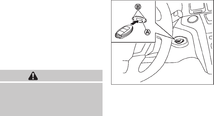
Black plate (301,1)
Model "Z51-D" EDITED: 2009/ 8/ 3
To lock the steering wheel, push the
ignition switch to the OFF position and
open any door. To unlock the steering
wheel, push the ignition switch. If the
steering lock release malfunction indicator
appears on the dot matrix liquid crystal
display, push the push-button ignition
switch again while lightly turning the
steering wheel right and left. (See “DOT
MATRIX LIQUID CRYSTAL DISPLAY” in the
“2. Instruments and controls” section.)
PUSH-BUTTON IGNITION SWITCH
POSITIONS
LOCK (Normal parking position)
The ignition switch can only be locked in this
position.
The ignition switch will be unlocked when it is
pushed to the ACC position while carrying the
Intelligent Key or with the Intelligent Key inserted
in the Intelligent Key port.
ACC (Accessories)
This position activates electrical accessories
such as the radio, when the engine is not
running.
ON (Normal operating position)
This position turns on the ignition system and
electrical accessories.
OFF
The engine can be turned off without locking the
steering wheel.
The ignition lock is designed so that the ignition
switch cannot be switched to the LOCK position
until the selector lever is moved to the P (Park)
position.
CAUTION
Do not leave the vehicle with the push-
button ignition switch in ACC or ON
positions when the engine is not run-
ning for an extended period. This can
discharge the battery.
SSD0837
KEY PORT
Starting and driving 5-11

Black plate (304,1)
Model "Z51-D" EDITED: 2009/ 8/ 3
2. Keep the foot brake pedal depressed and
move the selector lever to a driving position.
3. Release the parking brake and foot brake
pedal, and then gradually start the vehicle in
motion.
WARNING
.Do not depress the accelerator
pedal while shifting from P (Park)
or N (Neutral) to R (Reverse), D
(Drive) or L (Low) position. Always
depress the brake pedal until shift-
ing is completed. Failure to do so
could cause you to lose control and
have an accident.
.Cold engine idle speed is high, so
use caution when shifting into a
forward or reverse gear before the
engine has warmed up.
.Never shift to P (Park) or R (Re-
verse) while vehicle is moving. Fail-
ure to do so could cause you to lose
control and have an accident.
CAUTION
.When stopping the vehicle on an
uphill grade, do not hold the vehicle
by depressing the accelerator pedal.
The foot brake should be used for
this purpose.
.Do not downshift abruptly on slip-
pery roads. This may cause a loss of
control.
SSD0691
Shifting
To move the selector lever,
: Push the button *
Awhile depressing
the brake pedal.
: Push the button *
A.
: Just move the selector lever.
After starting the engine, fully depress the brake
pedal, push the selector lever button and move
the selector lever from the P (Park) position to
any of the desired shift positions.
5-14 Starting and driving
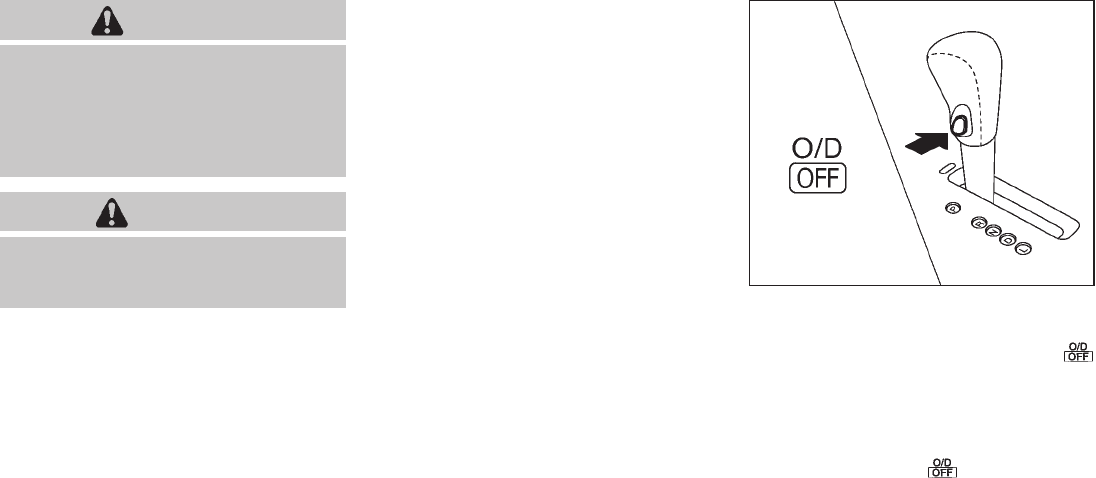
Black plate (305,1)
Model "Z51-D" EDITED: 2009/ 8/ 3
WARNING
Apply the parking brake if the selector
lever is in any position while the engine
is not running. Failure to do so could
cause the vehicle to move unexpectedly
or roll away and result in serious
personal injury or property damage.
CAUTION
Use the P (Park) or R (Reverse) position
only when the vehicle is completely
stopped.
P (Park):
Use this selector position when the vehicle is
parked or when starting the engine. Make sure
the vehicle is completely stopped. The brake
pedal must be depressed and the selector
lever button pushed in to move the selec-
tor lever from N (Neutral) or any drive
position to P (Park). Apply the parking brake.
When parking on a hill, apply the parking brake
first, then move the selector lever to the P (Park)
position.
R (Reverse):
Use this position to back up. Make sure the
vehicle is completely stopped before selecting
the R (Reverse) position. The brake pedal
must be depressed and the selector lever
button pushed in to move the selector
lever from P (Park), N (Neutral) or any
driving position to R (Reverse).
N (Neutral):
Neither forward nor reverse gear is engaged.
The engine can be started in this position. You
may shift to N (Neutral) and restart a stalled
engine while the vehicle is moving.
D (Drive):
Use this position for all normal forward driving.
L (Low):
Use this position for maximum engine braking on
steep downhill gradients/climbing steep slopes
and whenever approaching sharp bends. Do not
use the L position in any other circumstances.
SSD0692
Overdrive (O/D) OFF switch
When the O/D OFF switch is pushed with the
selector lever in the D (Drive) position, the
indicator light in the instrument panel illuminates.
Use the overdrive off mode when you need
improved engine braking.
To turn off the overdrive off mode, push the O/D
OFF switch again. The indicator light will
turn off.
Each time the engine is started, or when the
selector lever is shifted to any position other
than the D (Drive) position, the overdrive off
mode will be automatically turned off.
Starting and driving 5-15

Black plate (306,1)
Model "Z51-D" EDITED: 2009/ 8/ 3
Accelerator downshift
— In D position —
For passing or hill climbing, fully depress the
accelerator pedal to the floor. This shifts the
transmission down into a lower gear, depending
on the vehicle speed.
High fluid temperature protection mode
This transmission has a high fluid temperature
protection mode. If the fluid temperature be-
comes too high (for example, when climbing
steep grades in high temperature with heavy
loads, such as when towing a trailer), engine
power and, under some conditions, vehicle
speed will be decreased automatically to reduce
the chance of transmission damage. Vehicle
speed can be controlled with the accelerator
pedal, but the engine and vehicle speed may be
limited.
Fail-safe
If the vehicle is driven under extreme
conditions, such as excessive wheel spin-
ning and subsequent hard braking, the
fail-safe system may be activated. The MIL
may illuminate to indicate the fail-safe
mode is activated. (See “Malfunction In-
dicator Light (MIL)” in the “2. Instruments
and controls” section.) This will occur even
if all electrical circuits are functioning
properly. In this case, turn the ignition
switch to the OFF position and wait for 10
seconds. Then turn the ignition switch
back to the ON position. The vehicle
should return to its normal operating
condition. If it does not return to its normal
operating condition, have a NISSAN dealer
check the transmission and repair if ne-
cessary.
WARNING
When the high fluid temperature pro-
tection mode or fail-safe operation
occurs, vehicle speed may be gradually
reduced. The reduced speed may be
lower than other traffic, which could
increase the chance of a collision. Be
especially careful when driving. If ne-
cessary, pull to the side of the road at a
safe place and allow the transmission
to return to normal operation, or have it
repaired if necessary.
SSD0693
Shift lock release
If the battery charge is low or discharged, the
selector lever may not be moved from the P
(Park) position even with the brake pedal
depressed and the selector lever button pushed.
To move the selector lever, perform the following
procedure:
1. Push the ignition switch to the OFF or LOCK
position.
2. Apply the parking brake.
3. Remove the shift lock release cover *
A
using a suitable tool.
4. Push down the shift lock release *
Busing a
5-16 Starting and driving
Specyfikacje produktu
| Marka: | Nissan |
| Kategoria: | Automatyczny |
| Model: | Murano (2010) |
Potrzebujesz pomocy?
Jeśli potrzebujesz pomocy z Nissan Murano (2010), zadaj pytanie poniżej, a inni użytkownicy Ci odpowiedzą
Instrukcje Automatyczny Nissan

15 Października 2024
14 Października 2024
14 Października 2024
14 Października 2024
13 Października 2024
13 Października 2024
8 Października 2024
4 Października 2024
3 Października 2024
18 Września 2024
Instrukcje Automatyczny
- Automatyczny Peugeot
- Automatyczny Citroën
- Automatyczny Pioneer
- Automatyczny Fiat
- Automatyczny Honda
- Automatyczny Audi
- Automatyczny Volkswagen
- Automatyczny Saab
- Automatyczny Toyota
- Automatyczny GEM
- Automatyczny Opel
- Automatyczny Kia
- Automatyczny Dacia
- Automatyczny Subaru
- Automatyczny Ford
- Automatyczny Tesla
- Automatyczny Seat
- Automatyczny BMW
- Automatyczny Mini
- Automatyczny Land Rover
- Automatyczny Mazda
- Automatyczny Skoda
- Automatyczny Vauxhall
- Automatyczny Chrysler
- Automatyczny Volvo
- Automatyczny Suzuki
- Automatyczny Genesis
- Automatyczny Hyundai
- Automatyczny VDL
- Automatyczny Mercury
- Automatyczny Smart
- Automatyczny Jeep
- Automatyczny GMC
- Automatyczny Polaris
- Automatyczny Mercedes-Benz
- Automatyczny Lexus
- Automatyczny MG
- Automatyczny Alfa Romeo
- Automatyczny Chevrolet
- Automatyczny Jaguar
- Automatyczny Maserati
- Automatyczny DS
- Automatyczny Renault
- Automatyczny Mitsubishi
- Automatyczny Buick
- Automatyczny Audio-Technica
- Automatyczny RAM
- Automatyczny Rover
- Automatyczny Dodge
- Automatyczny Infiniti
- Automatyczny Lancia
- Automatyczny Tata
- Automatyczny Acura
- Automatyczny ACME
- Automatyczny Saturn
- Automatyczny Cadillac
- Automatyczny Pontiac
- Automatyczny Porsche
- Automatyczny Polestar
- Automatyczny Marklin
- Automatyczny Scion
- Automatyczny Aguilar
- Automatyczny Sharper Image
- Automatyczny Abarth
- Automatyczny Lincoln
- Automatyczny Mahindra
- Automatyczny Chery
- Automatyczny Lada
- Automatyczny Aston Martin
- Automatyczny McLaren
Najnowsze instrukcje dla Automatyczny

3 Kwietnia 2025
2 Kwietnia 2025

26 Marca 2025

13 Marca 2025
10 Marca 2025
10 Marca 2025
10 Marca 2025
9 Marca 2025
9 Marca 2025
9 Marca 2025