Instrukcja obsługi Midea MIH71GHN18
Midea
klimatyzacja
MIH71GHN18
Przeczytaj poniżej 📖 instrukcję obsługi w języku polskim dla Midea MIH71GHN18 (80 stron) w kategorii klimatyzacja. Ta instrukcja była pomocna dla 4 osób i została oceniona przez 2 użytkowników na średnio 4.5 gwiazdek
Strona 1/80
Read this manual carefully before using the product, and keep it handy for future reference.
The product picture on the cover page is for reference only.
Wall-Mounted Indoor Unit
Installation & Owner's Manual

Preface
Thank you for purchasing and using our product. Please read this manual carefully before you
install, use, maintain or troubleshoot this product so that you can familiarize yourself with the
product and use it correctly.
For ODUs or other IDUs, please refer to the applicable installation & owner's manuals provided
with them.
For detailed operation of auxiliary control devices, such as wired, remote and centralized
controllers, please refer to their instructions.
To ensure the correct installation and operation of the product, the following instructions are
provided:
Dear users,
To ensure the correct and safe operation of the product, please strictly follow the
requirements listed in this manual.
All figures and contents in this manual are for reference only. Due to continuing product
improvement, the specifications are subject to change without notice.
Regular cleaning and maintenance of the product are required for intended performance
and long service life. Each year before using the air conditioner, please contact your local
dealer, and we will assign professionals to provide paid services of cleaning, maintenance,
and inspection.
Please retain this manual for future reference.

Contents
Safety Warning 1
Warning Signs / 1 Safety Precautions / 2
Appendix / 3
Display Panel / 12
Operation 7
Operating Precautions / 7 Optimum Operation / 8
Installation 13
Installation Precautions / 13
Application Control / 54
Test Run / 59
Product Installation / 19
Cleaning, Maintenance and After-Sales Service 61
Safety Warning / 61 Cleaning and Maintenance / 61
Electric Safety Requirements / 3
Maintenance of Conventional Parts / 64
Symptoms That Are Not Faults / 10
Electrical Connection / 39
Safety Warning
01
Note
Useful operation and maintenance information.
Indicates a hazard with a medium level of risk which, if not avoided, could result in
death or serious injury.
Indicates a hazard with a high level of risk which, if not avoided, will result in death or
serious injury.
Indicates a hazard with a low level of risk which, if not avoided, could result in minor or
moderate injury.
Warning
Danger
Caution
Note
Safety Warning
Please thoroughly read and ensure that you fully understand the
safety precautions (including the signs and symbols) in this manual,
and follow relevant instructions during use to prevent damage to
health or property.
Different marks are used to indicate the levels of hazard severity. Please follow the instructions and
ensure safe operation.
Warning Signs
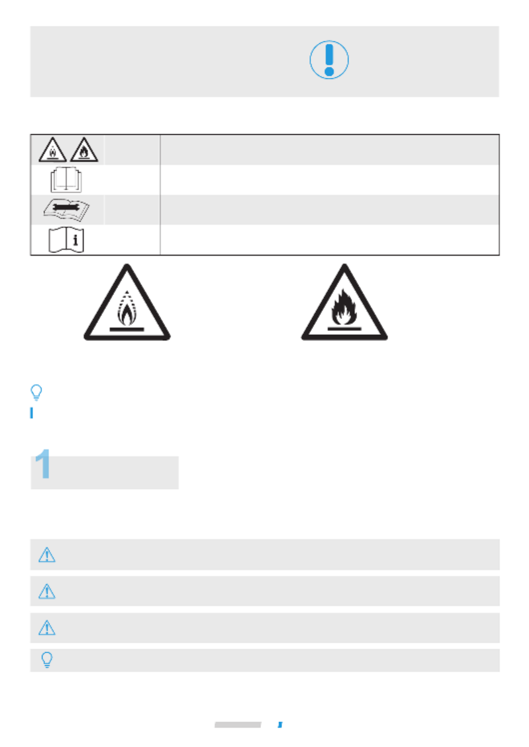
The symbols above is for R32 refrigerant system.
Explanation of symbols displayed on the unit
WARNING
CAUTION
CAUTION
CAUTION
This symbol shows that the operation manual should be read carefully.
This symbol shows that a service personnel should be handling this equipment with
reference to the installation manual.
This symbol shows that information is available such as the operating manual or
installation manual.
Cauti on: Risk of fire Cauti on: Risk of fire
(for IEC/EN 60335-2-40
except IEC 60335-2-40: 2018)
(for IEC 60335-2-40: 2018 only)
This symbol shows that this appliance used a flammable refrigerant. If the refrigerant
is leaked and exposed to an external ignition source, there is a risk of fire.
Safety Warning
02
Warning
Danger
Caution
Warning contents
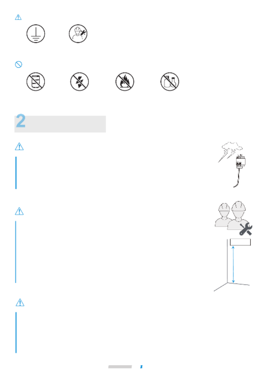
Prohibition signs
Ensure Proper
Grounding
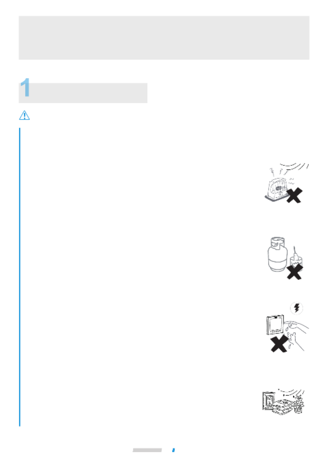
No Flammable
Materials
No Strong Current No Open Fire No Acid or Alkali
Materials
Professional Only
Indoor unit
>2.5m
Air conditioner installation must comply with local standards and electrical codes, and
relevant instructions in this manual.
Do not use any liquid cleanser, liquefied cleanser, or corrosive cleanser to wipe this unit or
spray water or other liquids on the unit. Otherwise, the plastic parts of the unit will become
damaged and an electrical shock may occur. Disconnect the main power switch before
cleaning and maintenance to avoid accidents.
Ask a professional to remove and reinstall the air conditioner.
Ask a professional for maintenance and repair assistance.
The IDU shall be placed at a height not accessible to children, at least 2.5m above the
ground.
This appliance is not intended for use by persons (including children) with reduced physical, sensory or
mental capabilities, or lack of experience and knowledge, unless they have been given supervision or
instruction concerning use of the appliance by a person responsible for their safety.
Children should be supervised to ensure that they do not play with the appliance.
The units are partial unit air conditioners, complying with partial unit requirements of this International
Standard, and must only be connected to other units that have been confirmed as complying to corresponding
partial unit requirements of this International Standard.
During thunderstorms, disconnect the main power switch. Otherwise, lightning may damage
the unit.
In the event of refrigerant leakage, smoking and open flames are prohibited. Disconnect the
main power switch immediately, open windows to allow ventilation, keep away from the
leakage point, and contact your local dealer or technical support to request a professional
repair.
Safety Precautions
OFF
Safety Warning
03
Warning
Warning
Caution
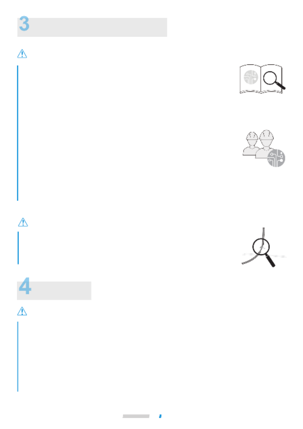
Electric Safety Requirements
The air conditioner shall be installed according to the local wiring specifications.
Wiring work must be completed by qualified electricians.
All wiring work must comply with electrical safety specifications.
The air conditioner must be well grounded. Specifically, the main switch of the air
conditioner must have a reliable grounding cable.
Before contacting wiring devices, cut off all the power supplies.
The user MAY NOT disassemble or repair the air conditioner. Doing so can be dangerous.
In the event of a fault, immediately cut off the power and contact your local dealer or
technical support.
A separate power supply that meets the rated parameter values must be provided for the
air conditioner.
The fixed wiring to which the air conditioner is connected must be equipped with a power
cut-off device that meets the wiring requirements.
To avoid danger, a damaged power cable must be replaced by professionals from the
maintenance department or a similar department of the manufacturer.
The air conditioner’s circuit board (PCB) is designed with a fuse to provide overcurrent
protection.
The specifications of the fuse are printed on the circuit board.
NOTE: For the units with R32 refrigerant , only the blast-proof ceramic fuse can be used.
Always ground the main power switch.
Do not use a damaged power cable and replace it if it is damaged.
When the air conditioner is used for the first time or is in a power-off state for a long
time, it needs to be connected to the power supply and warmed up for at least 12 hours
before use.
The following applies to R32 refrigerant systems.
Prior to beginning work on systems containing flammable refrigerants, safety checks are necessary to ensure
that the risk of ignition is minimized.
For repair to the refrigerating system, the following precautions shall be complied with prior to conducting work
on the system.
Work shall be undertaken under a controlled procedure so as to minimise the risk of a flammable gas or vapour
being present while the work is being performed.
All maintenance staff and others working in the local area shall be instructed on the nature of work being carried
out. Work in confined spaces shall be avoided. The area around the workspace shall be sectioned off. Ensure
that the conditions within the area have been made safe by control of flammable material.
Appendix

04 Safety Warning
The area shall be checked with an appropriate refrigerant detector prior to and during work, to ensure the
technician is aware of potentially flammable atmospheres.
Ensure that the leak detection equipment being used is suitable for use with flammable refrigerants, i.e.
non-sparking, adequately sealed or intrinsically safe.
If any hot work is to be conducted on the refrigeration equipment or any associated parts, appropriate fire
extinguishing equipment shall be available to hand. Have a dry powder or CO2 fire extinguisher adjacent to
the charging area.
No person carrying out work in relation to a refrigeration system which involves exposing any pipe work that
contains or has contained flammable refrigerant shall use any sources of ignition in such a manner that it may
lead to the riskof fire or explosion.
All possible ignition sources, including cigarette smoking, should be kept sufficiently far away from the site of
installation, repairing, removing and disposal, during which flammable refrigerant can possibly be released to
the surrounding space.
Prior to work taking place, the area around the equipment is to be surveyed to make sure that there are no
flammable hazards or ignition risks. “No Smoking” signs shall be displayed.
Ensure that the area is in the open or that it is adequately ventilated before breaking into the system or
conducting any hot work. A degree of ventilation shall continue during the period
that the work is carried out. The ventilation should safely disperse any released refrigerant and preferably expel
it externally into the atmosphere.
Where electrical components are being changed, they shall be fit for the purpose and to the correct specification.
At all times the manufacturer’s maintenance and service guidelines shall be followed. If in doubt consult the
manufacturer’s technical department for assistance.
The following checks shall be applied to installations using flammable refrigerants:
– the charge size is in accordance with the room size within which the refrigerant containing parts are installed;
– the ventilation machinery and outlets are operating adequately and are not obstructed;
– if an indirect refrigerating circuit is being used, the secondary circuit shall be checked for the presence of refrigerant;
– marking to the equipment continues to be visible and legible. Markings and signs that are illegible shall be corrected;
– refrigeration pipe or components are installed in a position where they are unlikely to be exposed to any substance
which may corrode refrigerant containing components, unless the components are constructed of materials which are
inherently resistant to being corroded or are suitably protected against being so corroded.
Repair and maintenance to electrical components shall include initial safety checks and component inspection
procedures.
If a fault exists that could compromise safety, then no electrical supply shall be connected to the circuit until it
is satisfactorily dealt with. If the fault cannot be corrected immediately but it is necessary to continue operation,
an adequate temporary solution shall be used. This shall be reported to the owner of the equipment so all parties
are advised.
Initial safety checks shall include:
-that capacitors are discharged: this shall be done in a safe manner to avoid possibility of sparking;
-that no live electrical components and wiring are exposed whiule charging, recovering or purging the system;
-that there is continuity of earth bonding.
During repairs to sealed components, all electrical supplies shall be disconnected from the equipment being
worked upon prior to any removal of sealed covers, etc. If it is absolutely necessary to have an electrical supply
to equipment during servicing, then a permanently operating form of leak detection shall be located at the most
critical point to warn of a potentially hazardous situation.
Particular attention shall be paid to the following to ensure that by working on electrical components, the casing
is not altered in such a way that the level of protection is affected. This shall include damage to cables, excessive
number of connections, terminals not made to original specification, damage to seals, incorrect fitting of glands,
etc.
Ensure that seals or sealing materials have not degraded such that they no longer serve the purpose of
preventing the ingress of flammable atmospheres.
Replacement parts shall be in accordance with the manufacturer’s specifications.
Do not apply any permanent inductive or capacitance loads to the circuit without ensuring that this will not
exceed the permissible voltage and current permitted for the equipment in use.
Intrinsically safe components are the only types that can be worked on while live in the presence of a flammable
atmosphere. The test apparatus shall be at the correct rating.
Replace components only with parts specified by the manufacturer. Other parts may result in the ignition of
refrigerant in the atmosphere from a leak.

05 Safety Warning
Check that cabling will not be subject to wear, corrosion, excessive pressure, vibration, sharp edges or any
other adverse environmental effects. The check shall also take into account the effects of ageing or continual
vibration from sources such as compressors or fans.
When breaking into the refrigerant circuit to make repairs – or for any other purpose – conventional procedures
shall be used. However, it is important that best practice is followed.
Since flammability is a consideration. The following procedure shall be adhered to:
• remove refrigerant;
• purge the circuit with inert gas;
• evacuate;
• purge again with inert gas;
• open the circuit by cutting or brazing.
The refrigerant charge shall be recovered into the correct recovery cylinders. The system shall be “flushed” with
OFN to render the unit safe. This process may need to be repeated several times. Compressed air or oxygen shall
not be used for this task.
Flushing shall be achieved by breaking the vacuum in the system with OFN and continuing to fill until the
working pressure is achieved, then venting to atmosphere, and finally pulling down to a vacuum.
This process shall be repeated until no refrigerant is within the system. When the final OFN charge is used, the
system shall be vented down to atmospheric pressure to enable work to take place.
This operation is absolutely vital if brazing operations on the pipe-work are to take place.
Ensure that the outlet for the vacuum pump is not close to any ignition sources and there is ventilation available.
Ensure that contamination of different refrigerants does not occur when using charging equipment. Hoses or
lines shall be as short as possible to minimise the amount of refrigerant contained in them.
Prior to recharging the system it shall be pressure tested with OFN.
DD.12 Decommissioning:
Before carrying out this procedure, it is essential that the technician is completely familiar with the equipment
and all its detail. It is recommended good practice that all refrigerants are recovered safely. Prior to the task
being carried out, an oil and refrigerant sample shall be taken in case analysis is required prior to re-use of
reclaimed refrigerant. It is essential that electrical power is available before the task is commenced.
a) Become familiar with the equipment and its operation.
b) Isolate system electrically.
c) Before attempting the procedure ensure that:
• mechanical handling equipment is available, if required, for handling refrigerant cylinders;
• all personal protective equipment is available and being used correctly;
• the recovery process is supervised at all times by a competent person;
• recovery equipment and cylinders conform to the appropriate standards.
d) Pump down refrigerant system, if possible.
e) If a vacuum is not possible, make a manifold so that refrigerant can be removed from various parts of the system.
f) Make sure that cylinder is situated on the scales before recovery takes place.
g) Start the recovery machine and operate in accordance with manufacturer's instructions.
h) Do not overfill cylinders. (No more than 80 % volume liquid charge).
i) Do not exceed the maximum working pressure of the cylinder, even temporarily.
j) When the cylinders have been filled correctly and the process completed, make sure that the cylinders and the
equipment are removed from site promptly and all isolation valves on the equipment are closed off.
k) Recovered refrigerant shall not be charged into another refrigeration system unless it has been cleaned and checked.
Equipment shall be labelled stating that it has been de-commissioned and emptied of refrigerant. The label shall
be dated and signed. Ensure that there are labels on the equipment stating the equipment contains flammable
refrigerant.
When removing refrigerant from a system, either for servicing or decommissioning, it is recommended good
practice that all refrigerants are removed safely.
When transferring refrigerant into cylinders, ensure that only appropriate refrigerant recovery cylinders are
employed. Ensure that the correct number of cylinders for holding the total system charge are available. All
cylinders to be used are designated for the recovered refrigerant and labelled for that refrigerant (i.e. special
cylinders for the recovery of refrigerant). Cylinders shall be complete with pressure relief valve and associated
shut-off valves in good working order. Empty recovery cylinders are evacuated and, if possible, cooled before
recovery occurs.
The recovery equipment shall be in good working order with a set of instructions concerning the equipment
that is at hand and shall be suitable for the recovery of flammable refrigerants. In addition, a set of calibrated
weighing scales shall be available and in good working order. Hoses shall be complete with leak-free disconnect

06 Safety Warning
couplings and in good condition. Before using the recovery machine, check that it is in satisfactory working
order, has been properly maintained and that any associated electrical components are sealed to prevent ignition
in the event of a refrigerant release. Consult manufacturer if in doubt.
The recovered refrigerant shall be returned to the refrigerant supplier in the correct recovery cylinder, and the
relevant Waste Transfer Note arranged. Do not mix refrigerants in recovery units and especially not in cylinders.
If compressors or compressor oils are to be removed, ensure that they have been evacuated to an acceptable
level to make certain that flammable refrigerant does not remain within the lubricant. The evacuation process
shall be carried out prior to returning the compressor to the suppliers. Only electric heating to the compressor
body shall be employed to accelerate this process. When oil is drained from a system, it shall be carried out
safely.
Warning: disconnect the appliance from its power source during service and when replacing parts.
These units are partial unit air conditioners, complying with partial unit requirements of this International
Standard, and must only be connected to other units that have been confirmed as complying to corresponding
partial unit requirements of this International Standard.
07 Operation
Warning
Operation
Operation Precautions
If the unit will be not used for a long time, disconnect the main power switch. Otherwise,
an accident may occur.
The installation height of the air conditioner shall be at least 2.5m above the ground to
avoid the following risks:
1. Touching of moving or live parts, such as fans, motors, or louvers, by a non professional.
Running parts may cause harm to you or transmission assemblies may become damaged.
2. Getting too close to the air conditioner may reduce the level of comfort.
When the product is used with a burning appliance, the room must be ventilated regularly.
Otherwise, it may cause an insufficient oxygen supply.
Do not let children play with the air conditioner. Otherwise, an accident may occur.
Do not expose the IDUs or controller to moisture or water as this may cause short
circuiting or fire.
Do not place any appliance that uses an open flame in the direct air supply of the air
conditioner as it could interfere with the combustion of the appliance.
Do not use or store flammable gases or liquids such as natural gas, hair spray, paint or
gasoline near the air conditioner. Otherwise, a fire may occur.
To avoid causing harm, do not place animals or plants directly in front of the air
conditioner's air supply.
In the event of abnormal conditions such as abnormal noise, smell, smoke, temperature
rise, and electric leakage, please cut off the power immediately, and then contact your
local dealer or air conditioner customer service center. Do not repair the air conditioner by
yourself.
Do not place flammable sprayers near the air conditioner or spray it directly at the air
conditioner. Otherwise, a fire may occur.
Do not place a container of water on the air conditioner. If immersed in water, the air
conditioner's electrical insulation will weaken, resulting in electrical shock.
After long-term use, confirm whether the installation platform has become worn. If it is
worn, the unit could fall, causing injury.
Do not operate the switch with wet hands, as this may result in electric shock.
When servicing the air conditioner, be sure to turn off the air conditioner and cut off the
power supply. Otherwise, the high-speed operation of the internal fan will cause injury.
The air conditioner cannot be used to preserve food, animals and plants, precision
instruments and works of art, etc.; otherwise, quality degradation could occur.
Do not use fuses like iron or copper wire other than those with the specified capacity.
Otherwise, a malfunction or fire may occur. The power supply must use the special circuit
of the air conditioner at the rated voltage.
Do not place valuables under the air conditioner. Air conditioner condensation problems
may damage the valuables.
When the air conditioner needs to be moved and re-installed, please entrust the local
dealer or a professional technician to operate it.

Installation
38
Warning
Danger
Caution
Electrical Connection
The power supply must be cut off before any electrical work is carried out. Do not conduct electrical work when the
power is on; otherwise, it may cause serious personal injury.
The air conditioning unit must be grounded reliably and must meet the requirements of the local country/region. If the
grounding is not reliable, serious personal injury due to electric leakage may occur.
Installation, inspection or maintenance operations must be completed by professional technicians. All parts and
materials must comply with the relevant regulations of the local country/region.
The air conditioning unit must be equipped with a special power supply, and the power supply voltage should conform
to the nominal working voltage range of the air conditioning unit.
The power supply of the air conditioning unit must be equipped with a power disconnect device that conforms to the
requirements of relevant local technical standards for electrical equipment. The power disconnecting device must have
the functions of short circuit protection, overload protection and electric leakage protection. The clearance between
open contacts of the power disconnecting device shall be at least 3mm.
The core of the power cable must be made of copper, and the wire diameter should meet the current-carrying
requirements. For details, refer to the "Power Cable Diameter and Electric Leakage Protector Selection". A wire
diameter that is too small may cause the power cable to heat up, resulting in a fire.
The power cable and the ground wire should be secured reliably to avoid stress on the terminals. Do not pull the power
cable forcibly; otherwise, the wiring may become loosened or the terminal blocks may be damaged.
Strong current wires such as power cables cannot be connected to weak current wires such as communication lines;
otherwise, the product may become seriously damaged.
Do not bond and connect the power cable. Bonding and connecting the power cable may cause it to heat up, resulting
in a fire.
Bonding and connecting the communication line should be avoided, but if it is used, at the very least, ensure a reliable
connection by crimping or soldering and make sure the copper wire at the connection is not exposed; otherwise,
communication failure may occur.
The power cable and communication line must be routed separately, with a distance of over 5 cm. Otherwise,
communication failure may occur.
Keep the vicinity of the air conditioning unit as clean as possible to avoid small animals from nesting and biting the
cables. If a small animal touches or bites the cables, short circuiting or electric leakage may occur.
Do not connect the ground wire to the gas pipe, water pipe, lightning rod ground wire or telephone ground wire.
Gas pipe: Risk of explosion and fire when gas leaks.
Water pipe: If rigid plastic pipes are used, there will be no grounding effect.
Lightning rod ground wire or telephone ground wire: In the event of lightning strikes, abnormal ground potential may
rise.
After all wiring is completed, check carefully before turning on the power supply.
Installation
39
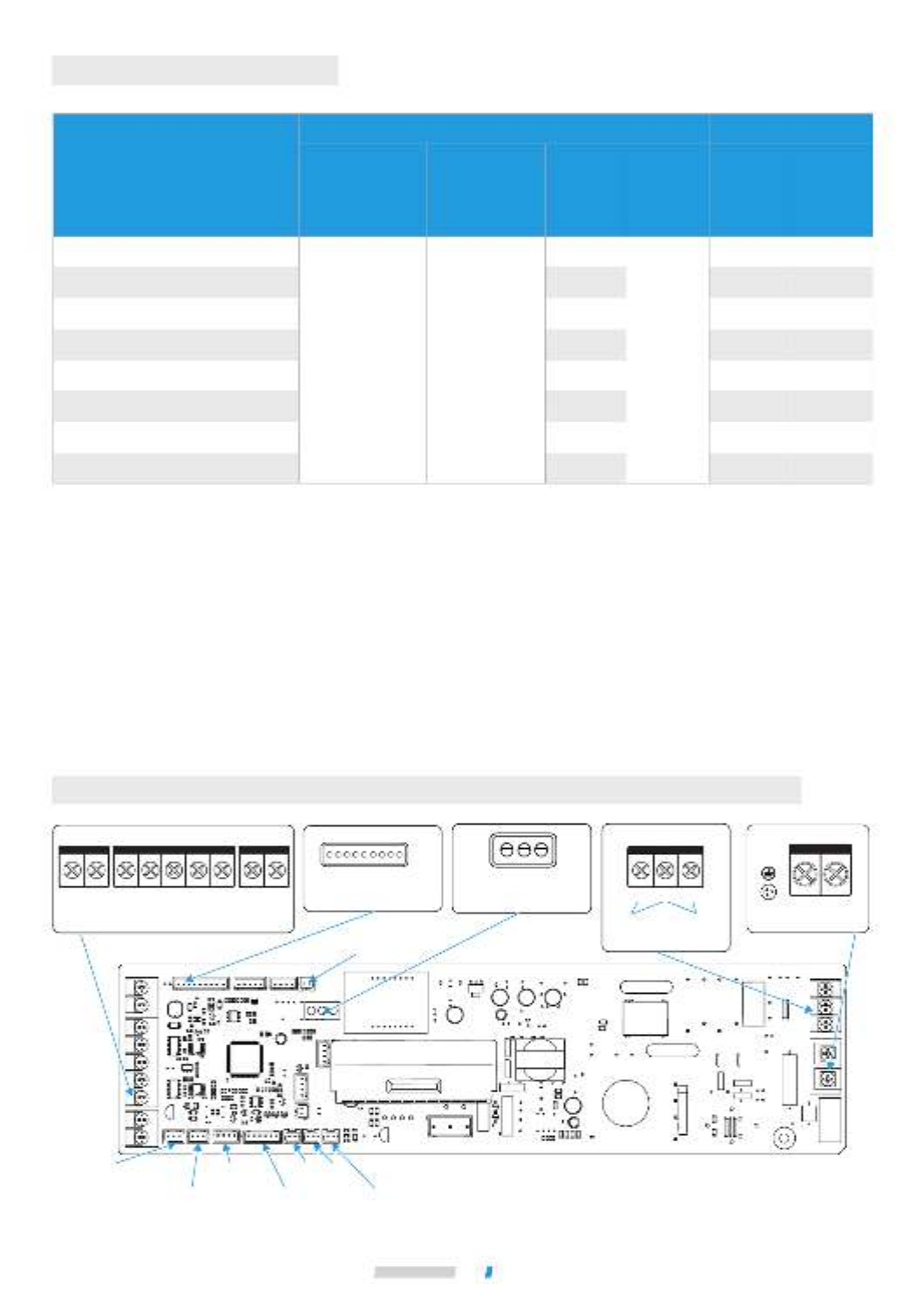
Schematic diagram of the main terminal blocks of main control board
Short-circuit terminal
(standard)/water
level switch
(optional)
Display panel
Electronic
expansion valve
T2AWater pump
T2 T2B
CN1
L N
CN22
N
3 2 1
Power cable and earth
line terminals
CN18
Switch module
CN55
Terminals of remote
switch signal
Terminals of
alarm signal
output
Terminals of
strong current
sterilization
module
CN6
M1 M2 X1 X2 P Q E
CN2
CN10
Terminals of communication line
D1(X) D2(Y)
T1
Electrical Characteristics
MCA: Min. Circuit Amps. (A), which is used to select the minimum circuit size to ensure safe operation over a long period
of time.
MFA: Max. Fuse Amps. (A), which is used to select the circuit breaker.
FLA: Full Load Amps. (A), which is the full load current of the indoor fan motor (reliable operation at the fastest speed
setting).
Notes:
Unit power
(kW)
Frequency
(Hz)
Voltage
(V)
MCA
(A)
MFA
(A)
FLA
(A)
50/60 220~240 15
1.5
2.2
2.8
3.6
4.5
5.6
7.1
8.0
0.28
0.29
0.36
0.39
0.41
0.51
0.65
0.98
20
20
20
20
20
20
50
50
0.22
0.23
0.29
0.31
0.33
0.33
0.55
0.78
Electric specifications of the IDU Indoor Fan Motor
Rated
Motor
Output
(W)
Installation
40
Caution
All weak point connection points meet SELV, such as X1, X2, P, Q, E, M1, M2, CN18, CN55 etc.
Wiring
Open the IDU's electric control box cover.
Loosen the screws on the right side of the electric control box cover and remove the electric control box
cover.
Electric control
box cover
Screw
(one)
Connect the strong current wires (power cable, alarm signal output wire, and strong current sterilization
wire) and weak current wires (communication line, expansion board connection wire, remote switch
connection wire) to the electric control box through the bottom of the electric control box, and the strong
and weak current inlets.
Strong current inlet
Power cable and
ground wire, etc.
Weak current inlet
Communication
cable and expansion
board connection
wire
Installation
41
Caution
Caution
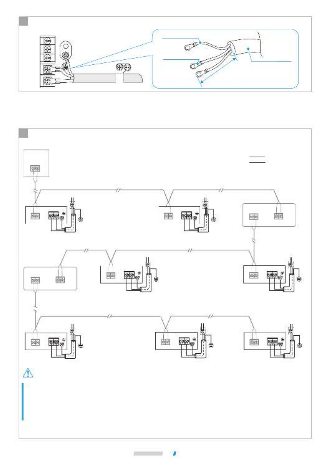
The power supply terminal of the IDU is fixed on the main control
board, the power cable is connected to the power supply terminal
labeled "CN1" on the main control board. The live and neutral wires
are connected according to the main control board logos "L" and "N",
and the ground wire is directly connected to the electric control box
sheet metal part.
Main control board
CN1
L N
Power input
Electric control
box sheet
metal part
1. Connection between the power cable and power supply terminal
Power cable
Circular
terminal
block
Connect wires of the
same diameter on both
sides.
B C
The power cable must be crimped reliably using an
insulated circular terminal block, and then connected
to the power supply terminal of the IDU, as shown in
the figure below.
ADo not bond and connect the power cable. Bonding and connecting the power cable may cause it to heat up,
resulting in a fire.
If it fails to crimp the insulated circular terminal block due
to on-site limitations, connect the power cables of the
same diameter to both sides of the power supply terminal
block of the IDU, as shown in the figure below.
Insulation sleeve
Do not connect wires of
the same diameter on
the same side.
DDo not press the power cables of the same wire diameter on the same side of the terminal. Do not use two power
cables of different wire diameters for the same terminal blocks; otherwise, they can easily loosen due to uneven
pressure and cause accidents, as shown in the figure below.
Do not connect wires
of different diameters.
Power cable connection
When there is a number of weak
current wires, making it impossible for
the cable clamp to fix all the wires,
please use two ST3.6*6.5 self-tapping
screws to fix the power cable clamp
from the accessory package on the
installation board, and fix those weak
current wires that cannot be fixed on
the drain pan here.
The strong and weak current wires must be separated.
The use of an adapter board and function expansion board are optional.
Water level switch terminals are shorted when the water level switch is unavailable.
Installation
42
Caution
When the IDUs are provided with independent power supplies, the IDUs in the same refrigerant system should be V8
IDUs*, and the communication between IDUs and ODU adopts a HyperLink with an independent power supply.
This connection method has the function of an independent power supply, so in the same refrigerant system, the
number of IDUs must not exceed 30 sets, and a maximum of only two repeaters may be installed*.
One repeater shall be added for every 10 IDUs or a communication distance of 200m added.
AIDUs are provided with independent power supplies*, which are wired as follows:
For HyperLink communication with independent power supply:
2. Power cable system connection
HyperLink repeater 1
CN3
CN2
TO UP IDU
TO DOWN IDU
···
IDU 2-9#
···
IDU 22-28#
IDU 1#
M1 M2
CN10
L1
La Lx
L11
Lb
Ly
L21 Lc L30
Power cable
Communication wire
···
IDU 12-19#
Circuit breaker
Power supply for IDU
××
M1 M2
CN23
Master ODU
L N
CN1 M1 M2
M1 M2
HyperLink repeater 2
CN3
CN2
TO UP IDU
TO DOWN IDU
M1 M2
M1 M2
IDU 10#
M1 M2
CN10
Circuit breaker
Power supply for IDU
××
L N
CN1
IDU 11#
M1 M2
CN10
Circuit
breaker
Power supply for IDU
××
L N
CN1
IDU 20#
M1 M2
CN10
Circuit breaker
Power supply for IDU
××
L N
CN1
IDU 21#
M1 M2
CN10
Circuit breaker
Power supply for IDU
××
L N
CN1
IDU 29#
M1 M2
CN10
Circuit breaker
Power supply for IDU
××
L N
CN1
IDU 30#
M1 M2
CN10
Circuit
breaker
Power supply for IDU
××
L N
CN1
Power cable
and ground
cable
Circular
crimping
terminal
Connecting
insulation sleeve
The connected power cable should be secured with a wire clamp to prevent loosening, as shown in the figure.
E
The stripped part of the cable
should not exceed 25mm
(or should not extend past the
electric control box)
L N
Power cable system connection depends on the forms of communication between the IDU and ODU. For the
HyperLink communication form with independent power supply, IDUs are allowed to have independent power supply.
For other communication forms, IDUs should be provided with uniform power supply.
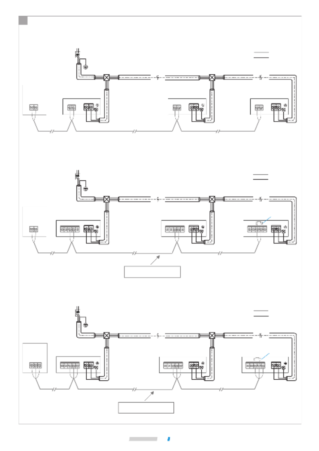
BIDUs are provided with uniform power supply*, which are wired as follows:
1. HyperLink communication with the uniform power supply:
2. P/Q communication:
3. P/Q/E communication:
M1 M2
CN23
Master ODU IDU (n-1)#
M1 M2 LN
CN1
CN10
···
2-(n-2)# IDU
IDU 1#
M1 M2 L N
CN1
CN10
Circuit breaker
Power supply for IDU
L1 La
Power cable
Communication wire
L1+La+Ln ≤ 2000m
IDU n#
M1 M2 LN
CN1
CN10
Ln
Wire diameter: 0.75mm2
Distribution box Distribution box
××
PQ
CN22
Master ODU IDU (n-1)#
LN
CN1
···
2-(n-2)# IDU
IDU 1#
L N
CN1
Circuit breaker
Power supply for IDU
L1 La
Power cable
Communication wire
IDU n#
Build-out
resistor
LN
CN1
Ln
Distribution box Distribution box
××
P Q
CN6
P Q
CN6
P Q
CN6
Use shielded cables and
ground the shield layer.
R
P Q
CN22
Master ODU IDU (n-1)#
LN
CN1
···
2-(n-2)# IDU
IDU 1#
L N
CN1
Circuit breaker
Power supply for IDU
L1 La
Power cable
Communication wire
IDU n#
LN
CN1
Ln
Distribution box Distribution box
××
P Q
CN6
Use shielded cables and
ground the shield layer.
EE P Q
CN6
E P Q
CN6
E
R
Build-out
resistor
Installation
43

Installation
44
Caution
Note
When the IDUs are provided with a uniform power supply, if the IDUs in the same refrigerant system are V8 IDUs, then
IDUs and ODU can communicate either via HyperLink with a uniform power supply, or via P/Q. If some of the IDUs in
the same refrigerant system are non-V8 series, then IDUs and ODU can only communicate via P/Q or P/Q/E
communication.
Both P/Q communication and HyperLink communication (M1M2) are indoor and outdoor communication, and only one
of them can be selected. Do not connect P/Q communication and HyperLink communication at the same time in the
same system. Do not connect HyperLink communication to P/Q or D1D2 communication.
Equipped with independently developed HyperLink (M1M2) communication, V8 series IDUs also preserve the previous
RS-485 (PQE) communication method. They are compatible with non-V8 IDUs. Pay attention to the type of IDU you have
purchased before connecting communication lines. Please refer to the following table to select an appropriate
communication method.
V8 IDUs: with V8 printed on the packaging carton
Independent power supply: With separate circuit breakers, the power supply for each IDU can be controlled
independently.
Uniform power supply: All the IDUs in the system are controlled by one circuit breaker.
Repeater: power supply repeater, which is used to compensate for the pressure drop due to excessive length of line or
line resistance when the main control board of the ODU provides an independent power supply for IDUs through the
HyperLink communication line. It is only used in refrigerant systems where IDUs are provided with an independent
power supply.
IDU type Optional communication method
between IDUs and ODU Remarks
Are all the IDUs in the
system V8 series
Are some of the IDUs in the
system non-V8 series
HyperLink (M1M2) communication
RS-485 (PQ) communication
RS-485 (PQE) communication
1. Independent power supply for IDUs*.
2. Any topology connection of
communication lines.
3. Two-core and non-polar
communication for M1M2.
1. Selection of communication method for IDUs
Communication line connection
1. The IDUs need to be powered
uniformly.
2. The communication cables must be
connected in serial.
3. Two-core and non-polar
communication for PQ.
1. The IDUs need to be powered
uniformly.
2. The communication cables must
be connected in serial.
3. PQE cables must be 3-core and
PQ non-polar.

Installation
45
Caution
Please select the communication line according to the requirements in the above reference table. Use shielded cables
for communication when strong magnetism or interference is present.
On-site wiring must comply with the relevant regulations of the local country/region and must be completed by
professionals.
Do not connect the communication line when the power is on.
Do not connect the power cable to the communication terminal; otherwise, the main control board may be damaged.
The standard value of the screw torque of the communication line terminal is 0.5N·m. Insufficient torque may cause
poor contact; excessive torque may damage the screws and power supply terminals.
Both HyperLink communication and PQ communication are internal and external, so only one of the two can be
selected. Do not connect both HyperLink communication line and PQ communication line to the same system,
otherwise the IDU and ODU cannot communicate normally.
If some of the IDUs in the same refrigerant system are non-V8 series, only P/Q/E communication can be selected for
the IDU and ODU communication. The three-core shielded cable of 3×0.75mm 2 is required to connect "P", "Q", and
"E".
Do not bundle the communication line with the refrigerant pipeline, power cable, etc. When the power cable and the
communication line are laid in parallel, a distance of more than 5cm should be maintained to prevent interference from
the signal source.
When the construction personnel of the IDU and ODU are working separately, information communication and
synchronization are required. Do not connect the ODU to HyperLink and the IDU to PQ. Do not connect the ODU to
PQ and the IDU to HyperLink.
Bonding and connecting the communication line should be avoided, but if it is used, at the very least, ensure a reliable
connection by crimping or soldering and make sure the copper wire at the connection is not exposed; otherwise,
communication failure may occur.
2. Table of selection of communication line diameter
Function IDU and ODU communication
Item
Wire
diameter
One controller to
one IDU
(two controllers
to one IDU)
communication
X1X2
communication
P/Q communication
(IDUs are powered
uniformly)
2 × 0.75mm2
(shielded cable)
2 × 0.75mm2
(shielded cable)
2 × 0.75mm2
(shielded cable)
HyperLink
communication
(IDUs are powered
uniformly)
HyperLink
communication
(IDUs are powered
independently)
2 × 1.5mm2
Wire resistance
≤ 1.33Ω/100m
2 × 0.75mm2
D1D2
communication
Length ≤ 200m≤ 1200m
P/Q/E communication
(IDUs are powered
uniformly)
3 × 0.75mm2
(shielded cable)
≤ 1200m≤ 2000m
≤ 600m
(add two repeaters) ≤ 1200m
One-to-more
(centralized
control)
communication
Installation
46
Caution
AHyperLink communication (with independent power supply)
Do not connect the HyperLink communication line to the PQ or D1D2 communication line.
L1+La+Lx ≤ 200m L11+Lb+Ly ≤ 200m L21+Lc+L30 ≤ 200m
For other connection methods (tree topology, star topology, ring topology), please refer to the technical manual or
consult technical personnel.
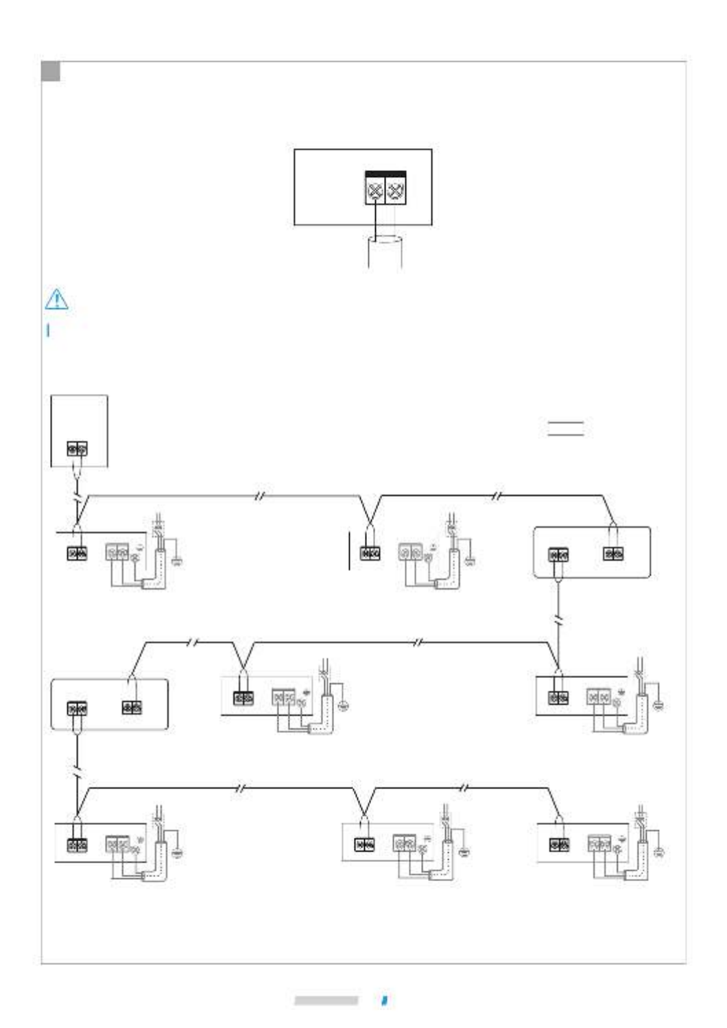
3. IDU and ODU communication
Single unit: HyperLink communication is a new type of IDU and ODU communication technology. When the IDUs
are provided with independent power supplies, use 2×1.5mm 2 communication cables. M1 and M2 ports
are located at terminal block "CN10" of the main control board. There is no distinction between negative
and positive electrodes. For details, see the following figure:
M1 M2
CN10
Connect to ODU M1M2
(HyperLink)
Main
control
board
System: The HyperLink communication line with an independent power supply between IDU and ODU can reach a
length of up to 600 meters, supporting any topology connection. The following figure shows a serial
connection:
HyperLink repeater 1
CN3
TO UP IDU
TO DOWN IDU
···
IDU 2-9#
···
IDU 22-28#
IDU 1#
M1 M2
CN10
L1
La Lx
L11
Lb
Ly
L21 Lc L30
Power cable
Communication wire
···
IDU 12-19#
Circuit breaker
Power supply for IDU
××
M1 M2
CN23
Master ODU
L N
CN1 M1 M2
M1 M2
HyperLink repeater 2
CN3
TO UP IDU
TO DOWN IDU
M1 M2
M1 M2
IDU 10#
M1 M2
CN10
Circuit breaker
Power supply for IDU
××
L N
CN1
IDU 11#
M1 M2
CN10
Circuit
breaker
Power supply for IDU
××
L N
CN1
CN2
CN2
IDU 20#
M1 M2
CN10
Circuit breaker
Power supply for IDU
××
L N
CN1
IDU 21#
M1 M2
CN10
Circuit breaker
Power supply for IDU
××
L N
CN1
IDU 29#
M1 M2
CN10
Circuit breaker
Power supply for IDU
××
L N
CN1
IDU 30#
M1 M2
CN10
Circuit
breaker
Power supply for IDU
××
L N
CN1
Installation
47
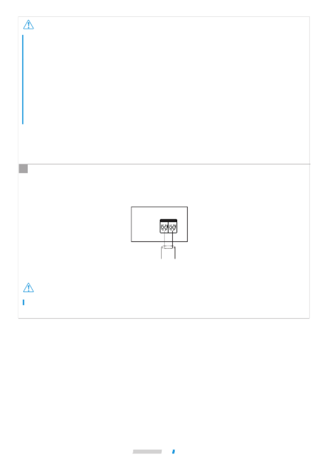
Caution
Caution
If the total distance is ≤ 200m and the total number of IDUs is ≤ 10 sets, the valve is powered and controlled by the
master ODU.
If the total distance is longer than 200m or the total number of IDUs is more than 10 sets, a repeater is required to
increase the bus voltage.
The load capacity of the repeater is the same as that of the ODU, and it can load a bus length of 200m or 10 IDUs.
The number of IDUs requiring power supply in the same refrigerant system does not exceed 30 sets.
A maximum of two repeaters can be installed in the same refrigerant system.
Keep the power on/off for both the repeater and the ODU, or use an uninterruptible power supply.
For repeater installation, refer to the repeater installation manual. Do not connect the upstream and downstream IDU
ports of the repeater in reverse; otherwise, it will cause a communication failure.
The repeater is optional. If you need to purchase it, please contact your local dealer.
Do not connect the HyperLink communication line to the PQ or D1D2 communication line.
Single unit: When the IDUs are provided with uniform power supply, it is not necessary for HyperLink communication
line to provide independent power supply for IDUs. In this case, use 2×0.75mm2 communication cables. M1
and M2 ports are located at terminal block "CN10" of the main control board. There is no distinction
between negative and positive electrodes. For details, see the following figure:
M1 M2
CN10
Connect to ODU M1M2
(HyperLink)
Main
control
board
BHyperLink communication (with uniform power supply)
Cleaning, Maintenance and After-Sales Service
62
Caution
Caution
Reinstall the filter in the reverse order of the steps above and put the panel back.
3
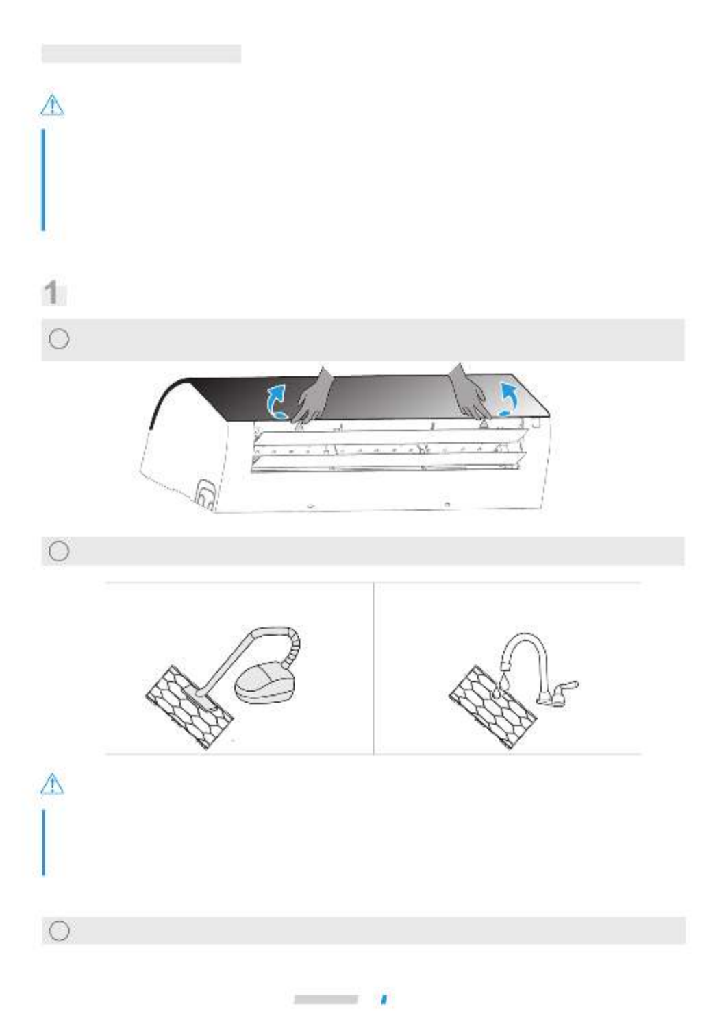
Cleaning the Air Filter
Air filters can be used to remove dust or other particles from the air, and if clogged, the effectiveness of the air
conditioner will be greatly reduced.
Therefore, be sure to clean the air filter frequently when using it for an extended period. If the unit is installed in a place
with a lot of dust, it is recommended that you clean the filter once a month.
If excess dirt makes the filter difficult to clean, replace the filter.
Do not remove the air filter unless it is being cleaned; otherwise, it may cause malfunction.
To avoid deformation of the filter, do not use fire or a burning appliance to dry the filter.
If the filter is heavily soiled, use a soft brush and neutral detergent to clean it, then shake off the water and dry it in a
cool place.
Non-professionals should not disassemble, replace or repair the filter.
Procedure diagram
Use two hands to hold the panel above theair outlet, open it in the direction of the arrow, and use one hand to
hold the panel and the other hand to lift the middle convex part of the filter and pull the filter out downwards.
1
Clean the filter and dry it in a cool place.
2
Clean the filter with a vacuum cleaner, with the
air inlet side of the filter facing upwards.
Clean the filter with clean water (except for the
activated carbon module), with the air inlet side
of the filter facing downwards.

Cleaning, Maintenance and After-Sales Service
63
Caution
Maintenance
During in-depth maintenance, the air conditioner should be cleaned and maintained by professional
technicians every 2 to 3 years.
Clean the filter regularly.
When operating in a dusty environment, the air flow and capacity of the filter will decrease. The filter may even
become blocked, and the air conditioner performance and indoor air compromised.
Preheat the unit in advance.
When the heating season comes, power on the ODU master unit for preheating more than 4 hours before use.
The preheating time depends on the weather temperature. This can make the air conditioner operate more stably
and help the refrigeration oil in the air conditioner compressor to maintain the best lubrication state, which can
prolong the service life of the compressor.
Complete the following steps before the air conditioner is put out of use for a long period:
1. If the air conditioner is not in use for a long time due to seasonal changes, keep the unit running for 4-5 hours
in fan mode until the unit becomes completely dry. Otherwise, it may grow mold indoors and have negative
health effects.
2. When not in use for a long time, power off or unplug the power plug to reduce standby power consumption,
and wipe the wireless remote controller with a clean soft dry cloth and remove the battery.
3. Turn on the power switch 12 hours before using the air conditioner again. In addition, in seasons when air
conditioners are frequently used, keep the power switch on. Otherwise, failures may occur.
Before the air conditioner is idle for a long time, the internal components of the ODUs should be checked and cleaned
regularly. For more details, please contact the local air conditioner customer service center or special technical
service department.
Check the return air inlet and outlet of the ODU and IDU after long periods of use to see if they are blocked; if an
inlet/outlet is blocked, clean it immediately.
Cleaning, Maintenance and After-Sales Service
64
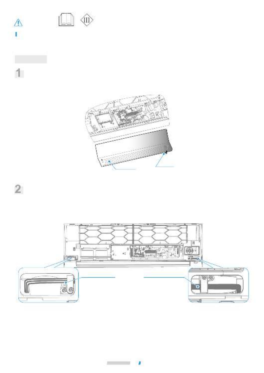
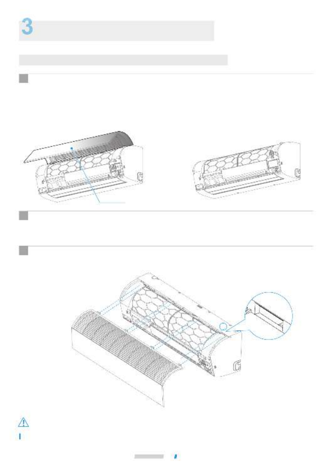
Panel assembly
Disassembly and Installation of Panel and IDU Wiring
Dismantle the panel assembly
Make sure that the front buckles of the panel fit the unit well, otherwise condensation and other risks may occur.
Maintenance of Conventional Parts
Disassembly of the Front Panel
There is no need to disassemble the panel frame when confirming the electrical cable distribution and condensed
water drainage.
① Pull out slightly on the panel from the buckle position on both sides of the unit body.
② Take the panel off the buckles along the gap between the panel and the unit body. Remove the panel obliquely
upward.
③ Hold the two lower ends of the front panel, gently pull the panel and then push the panel upward to remove it.
1
IDU wiring
Lead the power cable, ground wire, and signal cable from the back of the indoor unit to the front. For detailed
wiring steps, refer to section "Installation Instructions - Electrical Connection".
2
Installation of Front Panel
① Insert the upper buckles of the panel into the buckles on the panel frame.
② Place the panel and press the buckles.
3
Caution
Cleaning, Maintenance and After-Sales Service
66
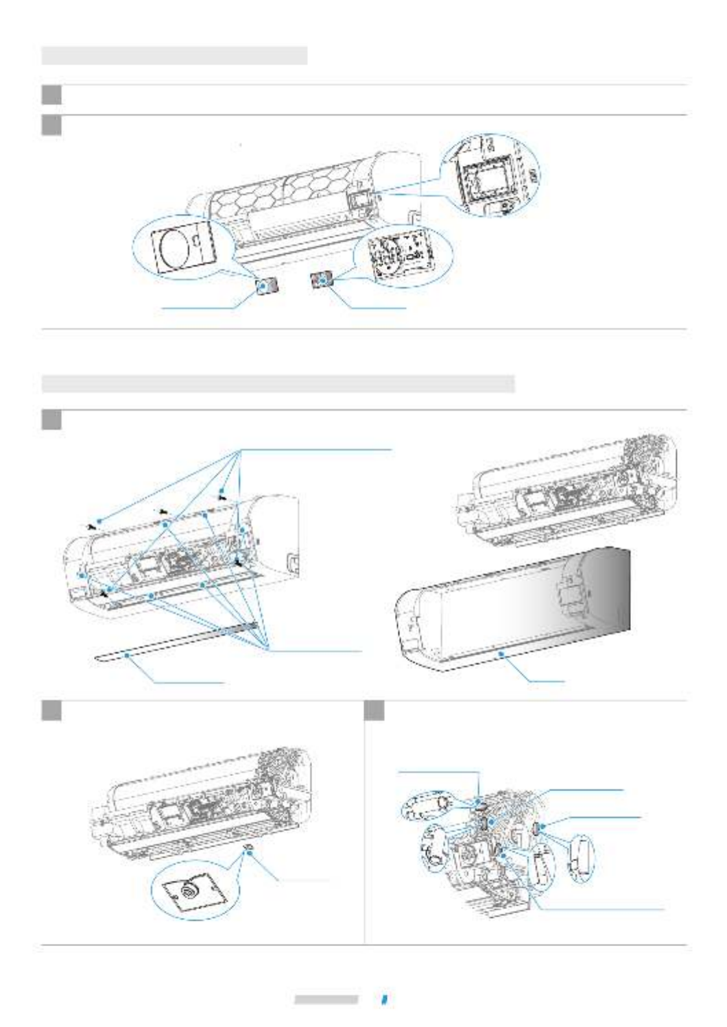
First remove the display box cover, then remove the display panel and unplug the cable.
Maintenance of Display Panel
2
Follow the steps above to dismantle the panel assembly.
1
Display panel
Display box cover
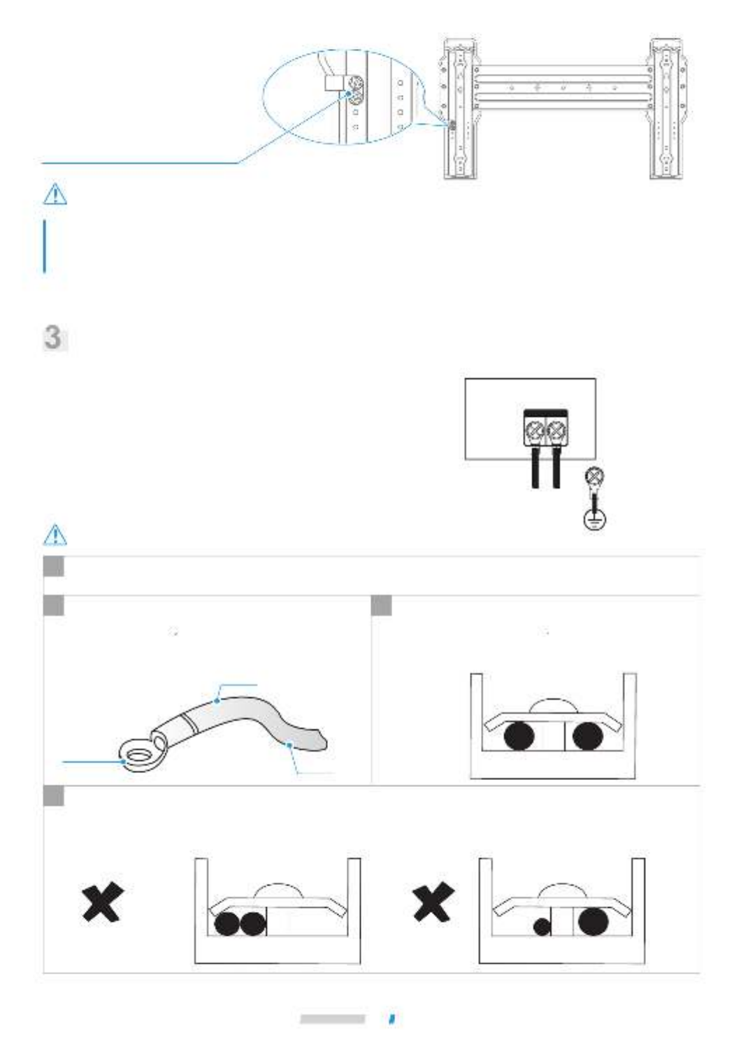
Maintenance of Infrared Human Sensor, Temperature
Sensor, Drain Pump and Water Level Switch
Remove the upper and lower louver near the screw hole, loosen the screws, and then remove
the panel frame.
1
Panel frame
Upper and lower
louvers
Screw
(Four for model 22/28/36,
five for model 45/56,
and seven for model 71/80)
Spring buckle
(six for model 45/56, and
four for other models)
Take out the infrared human sensor, remove the
connecting cable and repair the sensor.
2Pull the temperature sensor out of the buckle or sleeve,
pull the plug out of the electric control box and repair
the temperature sensor.
3
Infrared
human sensor
(optional)
T2B
(on the output tube)
T2A
(on the capillary tube) T2 (on a semicircular tube)
Room temperature sensor
(on the side of the display panel
mounting bracket)
④ Water
level switch
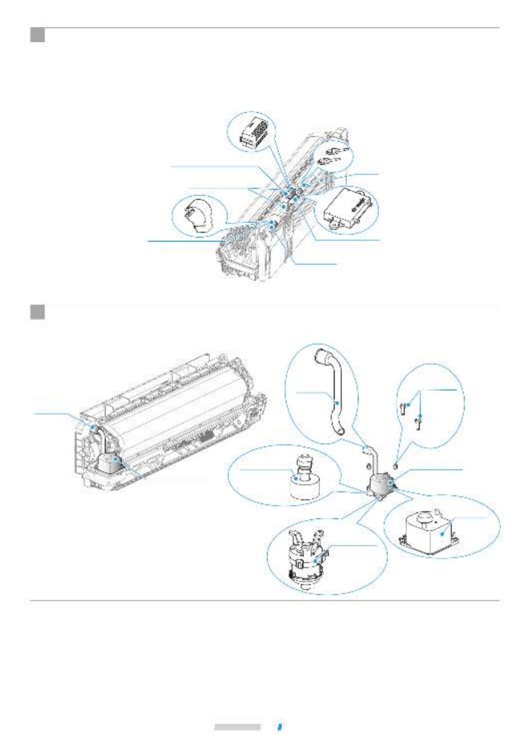
Plasma generator (optional):
① Remove the screws (two).
② Pull out the electrode, remove the plasma generator and repair it.
Humidity sensor: Remove the humidity sensor cable from the electric control board, pull out the humidity sensor and
repair it.
Electronic expansion valve coil: Remove the electronic expansion valve coil cable from the electric control board,
pull out the coil and repair it.
4
Screw (two)
Drain pump assembly
Remove the water pump and water level switch cable from the electric control board, pull out the drainage ①
pipe from the chassis outlet, loosen the two screws fixing the drain pump mounting base, remove the drain ②
pump assembly, loosen the screws securing the drain pump, remove the drain pump to repair it, and ③ ④
remove the water level switch to repair it.
5
Drain pump assembly
(optional)
Electrode
Electronic expansion valve
Electronic expansion valve coil Plasma generator (optional)
Humidity sensor (optional)
Drain
nozzle
① Drainage
pipe
② Screw
(two)
Drain
pump
mounting
base
③ Drain
pump
Cleaning, Maintenance and After-Sales Service
67
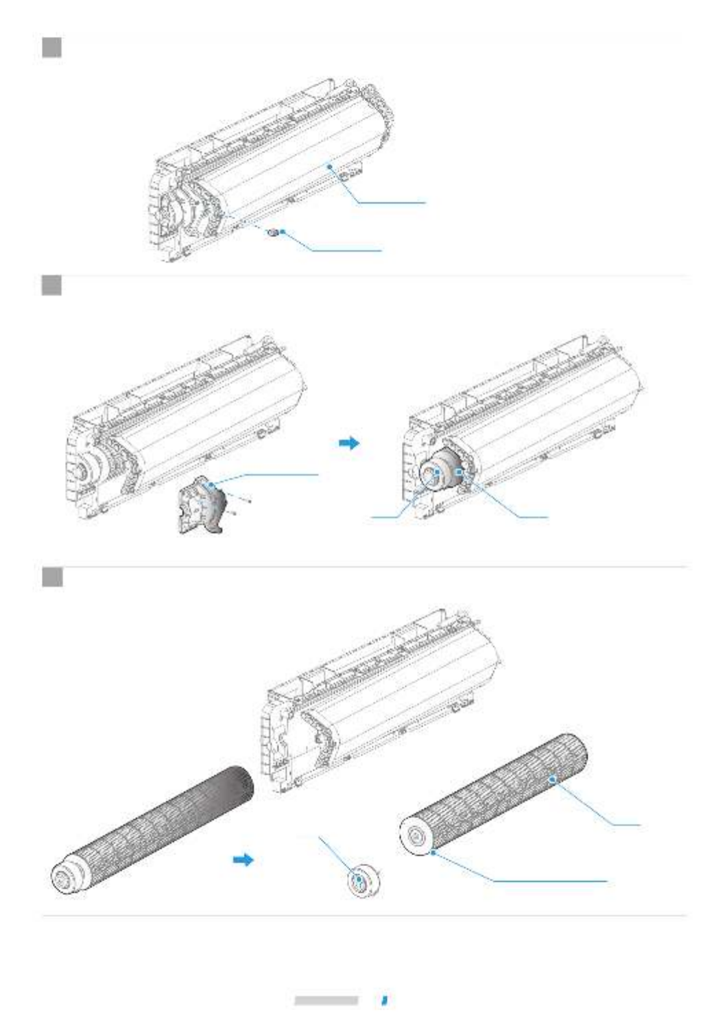
69 Cleaning, Maintenance and After-Sales Service
Take the motor and wind wheel out horizontally; loosen the screws fixing the motor and wind wheel, and repair the
motor and wind wheel.
5
Loosen the screws (two), swivel out slightly and take out the motor mounting rack (hold the motor and prevent it
from falling). Pull out the motor and wind wheel horizontally.
4
Wind wheel screws are tightened
on the wind wheel shaft sleeve
Motor mounting rack
Motor Fan
Fan
Motor
Loosen the screw (one), pull the evaporator horizontally a little and hang the evaporator.
3
Evaporator
Screw (one)
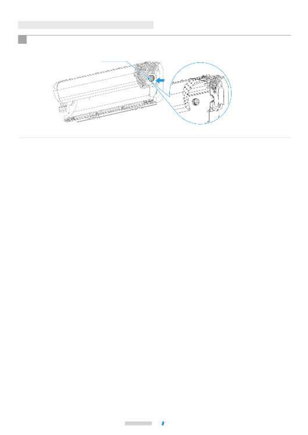
70 Cleaning, Maintenance and After-Sales Service
Follow the steps above to remove the motor and wind wheel; push the wind wheel bearing to remove and repair it.
1
Maintenance of Wind Wheel Bearing
Wind wheel bearing
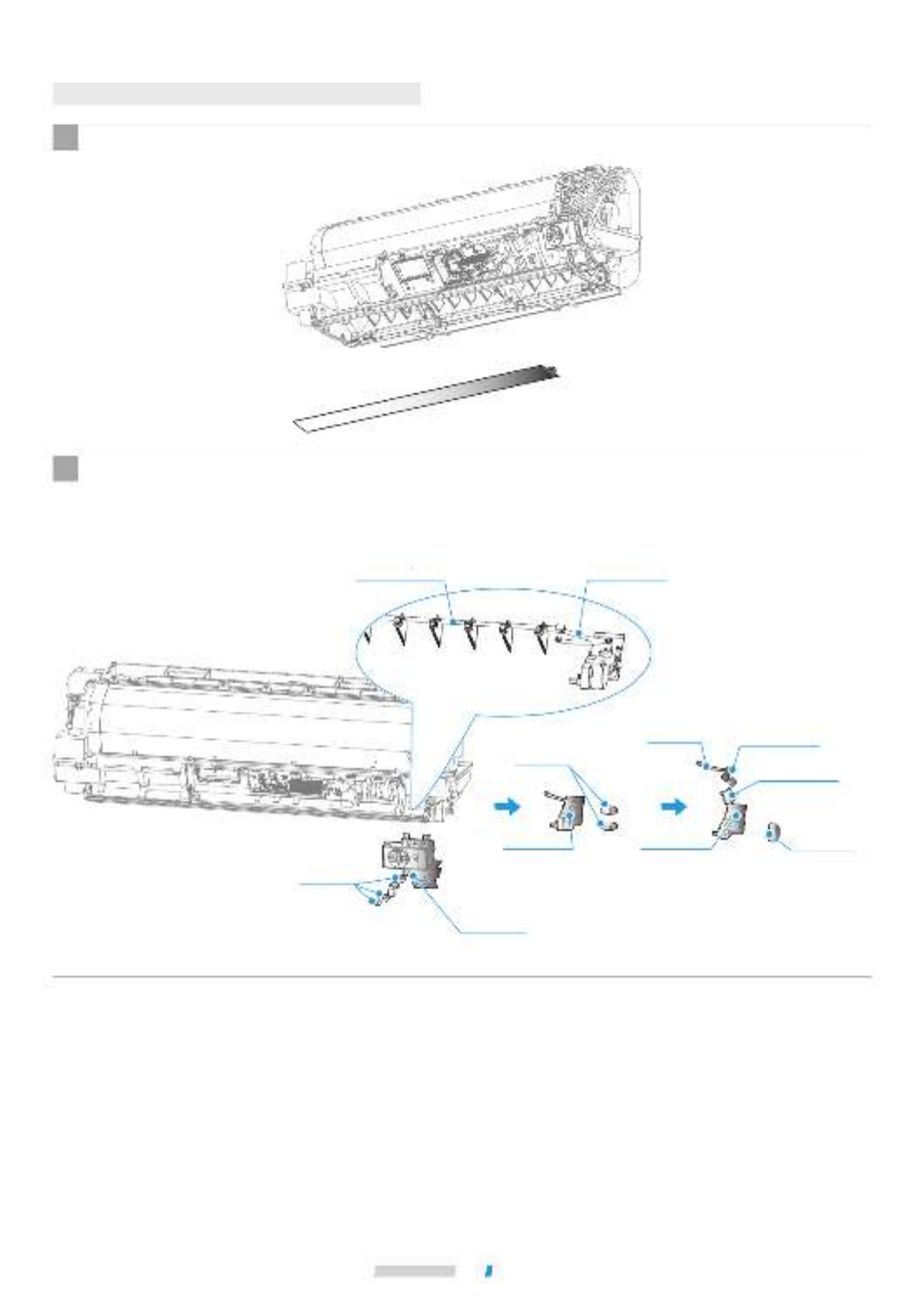
Follow the steps above to remove the panel frame and upper and lower louvers.
1
First loosen the screws (three) to remove the display panel, remove the cable terminal on the oscillation motor, then
disconnect the left and right louver rod and the left and right swing motor rod, and take the swing motor and repair
it.
2
Maintenance of Oscillation Motor
Display panel
Oscillation motor
Screw
(three)
Left/right oscillation
motor rod
Screw
(two)
Oscillation
motor base
Connecting rod Crank rod
Left and right
louver rod
Left/right swing
motor
(optional)
Up/down
swing motor
Cleaning, Maintenance and After-Sales Service
71


16126000007230 V.F


Specyfikacje produktu
| Marka: | Midea |
| Kategoria: | klimatyzacja |
| Model: | MIH71GHN18 |
Potrzebujesz pomocy?
Jeśli potrzebujesz pomocy z Midea MIH71GHN18, zadaj pytanie poniżej, a inni użytkownicy Ci odpowiedzą
Instrukcje klimatyzacja Midea

9 Kwietnia 2025
12 Marca 2025
12 Marca 2025
12 Marca 2025
12 Marca 2025
12 Marca 2025
17 Lutego 2025
12 Lutego 2025
12 Lutego 2025
12 Lutego 2025
Instrukcje klimatyzacja
- klimatyzacja Bauknecht
- klimatyzacja Samsung
- klimatyzacja Electrolux
- klimatyzacja DeLonghi
- klimatyzacja AEG
- klimatyzacja Balay
- klimatyzacja Beko
- klimatyzacja LG
- klimatyzacja Gorenje
- klimatyzacja LERAN
- klimatyzacja Sharp
- klimatyzacja TCL
- klimatyzacja Russell Hobbs
- klimatyzacja Philips
- klimatyzacja Livoo
- klimatyzacja Dometic
- klimatyzacja Bosch
- klimatyzacja SHE
- klimatyzacja Candy
- klimatyzacja Whirlpool
- klimatyzacja Fujitsu
- klimatyzacja Ferroli
- klimatyzacja Easy Home
- klimatyzacja Kärcher
- klimatyzacja Hisense
- klimatyzacja Infiniton
- klimatyzacja Panasonic
- klimatyzacja Theben
- klimatyzacja Nedis
- klimatyzacja Be Cool
- klimatyzacja Medion
- klimatyzacja Black & Decker
- klimatyzacja OK
- klimatyzacja Adler
- klimatyzacja Toshiba
- klimatyzacja Tesla
- klimatyzacja Westinghouse
- klimatyzacja Rinnai
- klimatyzacja Domo
- klimatyzacja GE
- klimatyzacja Ardes
- klimatyzacja Taurus
- klimatyzacja Orbegozo
- klimatyzacja Blaupunkt
- klimatyzacja Brandt
- klimatyzacja Vivax
- klimatyzacja Siemens
- klimatyzacja Danby
- klimatyzacja Einhell
- klimatyzacja Grundig
- klimatyzacja APC
- klimatyzacja Haier
- klimatyzacja Sigma
- klimatyzacja Jocel
- klimatyzacja Hyundai
- klimatyzacja Bimar
- klimatyzacja Rowenta
- klimatyzacja Mesko
- klimatyzacja Master
- klimatyzacja Honeywell
- klimatyzacja Concept
- klimatyzacja Tripp Lite
- klimatyzacja ECG
- klimatyzacja Unold
- klimatyzacja Remeha
- klimatyzacja Truma
- klimatyzacja Ozito
- klimatyzacja Sanus
- klimatyzacja Broan
- klimatyzacja Hotpoint
- klimatyzacja Kenwood
- klimatyzacja Sungrow
- klimatyzacja Friedrich
- klimatyzacja Trisa
- klimatyzacja Ariston Thermo
- klimatyzacja Zelmer
- klimatyzacja Mestic
- klimatyzacja Wilfa
- klimatyzacja BLUEPALM
- klimatyzacja Amana
- klimatyzacja Hotpoint Ariston
- klimatyzacja Furrion
- klimatyzacja Bomann
- klimatyzacja Teesa
- klimatyzacja Emerio
- klimatyzacja Wood's
- klimatyzacja Create
- klimatyzacja H.Koenig
- klimatyzacja InAlto
- klimatyzacja Meireles
- klimatyzacja Melissa
- klimatyzacja TechniSat
- klimatyzacja Daikin
- klimatyzacja Alaska
- klimatyzacja Stirling
- klimatyzacja MPM
- klimatyzacja OneConcept
- klimatyzacja Philco
- klimatyzacja Corbero
- klimatyzacja Zanussi
- klimatyzacja Ravanson
- klimatyzacja Thermex
- klimatyzacja GoldAir
- klimatyzacja Koenic
- klimatyzacja Trotec
- klimatyzacja Thomson
- klimatyzacja Klarstein
- klimatyzacja Manta
- klimatyzacja Vaillant
- klimatyzacja Bavaria
- klimatyzacja Cecotec
- klimatyzacja Waeco
- klimatyzacja Camry
- klimatyzacja NewAir
- klimatyzacja Keystone
- klimatyzacja Qlima
- klimatyzacja HTW
- klimatyzacja Sôlt
- klimatyzacja Eden
- klimatyzacja GUTFELS
- klimatyzacja TriStar
- klimatyzacja Exquisit
- klimatyzacja Bartscher
- klimatyzacja Mitsubishi
- klimatyzacja Dimplex
- klimatyzacja Baxi
- klimatyzacja Arçelik
- klimatyzacja Lavorwash
- klimatyzacja Gree
- klimatyzacja DCG
- klimatyzacja Daizuki
- klimatyzacja G3 Ferrari
- klimatyzacja Omega Altise
- klimatyzacja AKAI
- klimatyzacja Sanyo
- klimatyzacja Remko
- klimatyzacja Clatronic
- klimatyzacja Telefunken
- klimatyzacja Oregon Scientific
- klimatyzacja Calor
- klimatyzacja Inventum
- klimatyzacja SVAN
- klimatyzacja IFB
- klimatyzacja Princess
- klimatyzacja Carson
- klimatyzacja Innoliving
- klimatyzacja Argoclima
- klimatyzacja Heller
- klimatyzacja Aermec
- klimatyzacja Comfee
- klimatyzacja Bonaire
- klimatyzacja Meaco
- klimatyzacja Kenmore
- klimatyzacja VOX
- klimatyzacja Insignia
- klimatyzacja Frilec
- klimatyzacja Element
- klimatyzacja Orima
- klimatyzacja Aspes
- klimatyzacja Hitachi
- klimatyzacja Blumfeldt
- klimatyzacja Emerson
- klimatyzacja SereneLife
- klimatyzacja Frigidaire
- klimatyzacja CyberPower
- klimatyzacja EcoFlow
- klimatyzacja RCA
- klimatyzacja Climadiff
- klimatyzacja Whynter
- klimatyzacja Ridgid
- klimatyzacja Lanaform
- klimatyzacja Electroline
- klimatyzacja Kelvinator
- klimatyzacja Sencor
- klimatyzacja Mistral
- klimatyzacja Nabo
- klimatyzacja Fuave
- klimatyzacja Kalorik
- klimatyzacja Avidsen
- klimatyzacja Suntec
- klimatyzacja Be Quiet!
- klimatyzacja Carrier
- klimatyzacja Geist
- klimatyzacja Esatto
- klimatyzacja Daewoo
- klimatyzacja Livington
- klimatyzacja Consul
- klimatyzacja Kunft
- klimatyzacja Zibro
- klimatyzacja Becken
- klimatyzacja Guzzanti
- klimatyzacja Cool-Space
- klimatyzacja KuulAire
- klimatyzacja Alpatec
- klimatyzacja Volteno
- klimatyzacja ActronAir
- klimatyzacja Tectro
- klimatyzacja Eurom
- klimatyzacja Sauber
- klimatyzacja PRIME3
- klimatyzacja Sonnenkönig
- klimatyzacja Proline
- klimatyzacja Toyotomi
- klimatyzacja Soler & Palau
- klimatyzacja Monzana
- klimatyzacja Finlux
- klimatyzacja Challenge
- klimatyzacja Bestron
- klimatyzacja Yolco
- klimatyzacja AireMax
- klimatyzacja Rotel
- klimatyzacja Profile
- klimatyzacja Columbia Vac
- klimatyzacja Airwell
- klimatyzacja Amcor
- klimatyzacja Argo
- klimatyzacja KDK
- klimatyzacja Anslut
- klimatyzacja Coolix
- klimatyzacja Tosot
- klimatyzacja Korona
- klimatyzacja Progress
- klimatyzacja Tomado
- klimatyzacja Vestel
- klimatyzacja Itho
- klimatyzacja Mabe
- klimatyzacja Logik
- klimatyzacja Profilo
- klimatyzacja Heinner
- klimatyzacja Termozeta
- klimatyzacja Eldom
- klimatyzacja Jocca
- klimatyzacja Defy
- klimatyzacja Premium
- klimatyzacja White Knight
- klimatyzacja GlobalTronics
- klimatyzacja Evolar
- klimatyzacja Kubo
- klimatyzacja Elba
- klimatyzacja Royal Sovereign
- klimatyzacja Ansonic
- klimatyzacja Malmbergs
- klimatyzacja Everglades
- klimatyzacja Heylo
- klimatyzacja ElectriQ
- klimatyzacja Listo
- klimatyzacja Daitsu
- klimatyzacja Ufesa
- klimatyzacja Milectric
- klimatyzacja Olimpia Splendid
- klimatyzacja Saunier Duval
- klimatyzacja Duux
- klimatyzacja Primo
- klimatyzacja Godrej
- klimatyzacja Maiko
- klimatyzacja Conrad
- klimatyzacja Igenix
- klimatyzacja Essentiel B
- klimatyzacja Team
- klimatyzacja Equation
- klimatyzacja Edy
- klimatyzacja Edgestar
- klimatyzacja Maxicool
- klimatyzacja Dantherm
- klimatyzacja Carrefour Home
- klimatyzacja Equator
- klimatyzacja HQ
- klimatyzacja Noveen
- klimatyzacja BOSFOR
- klimatyzacja MundoClima
- klimatyzacja Proklima
- klimatyzacja Home Electric
- klimatyzacja Eco-De
- klimatyzacja Fairland
- klimatyzacja Aconatic
- klimatyzacja Duracraft
- klimatyzacja DEXP
- klimatyzacja Just Fire
- klimatyzacja Teco
- klimatyzacja Iceberg
- klimatyzacja Khind
- klimatyzacja Chigo
- klimatyzacja Hokkaido
- klimatyzacja Tarrington House
- klimatyzacja Firstline
- klimatyzacja Holland Electro
- klimatyzacja Evapolar
- klimatyzacja Orava
- klimatyzacja Elgin
- klimatyzacja Tronix
- klimatyzacja Ausclimate
- klimatyzacja Liebert
- klimatyzacja Sencys
- klimatyzacja Fronius
- klimatyzacja Avalon Bay
- klimatyzacja SMC
- klimatyzacja D-Let
- klimatyzacja Kogan
- klimatyzacja Braemar
- klimatyzacja Klimaire
- klimatyzacja General
- klimatyzacja SEEGER
- klimatyzacja General Electric
- klimatyzacja SPT
- klimatyzacja Simplicity
- klimatyzacja Starlyf
- klimatyzacja Aerian
- klimatyzacja Moa
- klimatyzacja Fuji Electric
- klimatyzacja Polocool
- klimatyzacja Convair
- klimatyzacja Kibernetik
- klimatyzacja Fral
- klimatyzacja Companion
- klimatyzacja Prem-i-air
- klimatyzacja Arcoaire
- klimatyzacja Céliera
- klimatyzacja Bodin
- klimatyzacja Magnavox
- klimatyzacja AFINTEK
- klimatyzacja Brivis
- klimatyzacja MRCOOL
- klimatyzacja B-Air
- klimatyzacja Trilec
- klimatyzacja Kaden
- klimatyzacja Avallon
- klimatyzacja TURBRO
- klimatyzacja BISWIND
- klimatyzacja House & Luft
- klimatyzacja Evapcool
- klimatyzacja Protector
- klimatyzacja Vostok
- klimatyzacja American Comfort
- klimatyzacja Ocean Breeze
- klimatyzacja Quirky
- klimatyzacja Krone
- klimatyzacja KwiKool
- klimatyzacja Big Ass Fans
- klimatyzacja Arctic King
- klimatyzacja Artrom
- klimatyzacja Senville
- klimatyzacja Climachill
- klimatyzacja Commercial Cool
- klimatyzacja Riffel
- klimatyzacja Heat Controller
- klimatyzacja Luma Comfort
- klimatyzacja Norpole
- klimatyzacja Kaco
- klimatyzacja Middle Atlantic
- klimatyzacja Goodwe
- klimatyzacja Swegon
- klimatyzacja JHS
- klimatyzacja FREONIC
- klimatyzacja ARCTIC WIND
- klimatyzacja VänEE
- klimatyzacja Mayer
- klimatyzacja Perfect Aire
- klimatyzacja Koldfront
- klimatyzacja Yamazen
- klimatyzacja Universal Blue
- klimatyzacja Symphony
- klimatyzacja Corona
- klimatyzacja Sheffield
- klimatyzacja Hoffman
Najnowsze instrukcje dla klimatyzacja

9 Kwietnia 2025
9 Kwietnia 2025

9 Kwietnia 2025
9 Kwietnia 2025
9 Kwietnia 2025

9 Kwietnia 2025
9 Kwietnia 2025
9 Kwietnia 2025
9 Kwietnia 2025
9 Kwietnia 2025