Instrukcja obsługi Marantz SR-4600
Przeczytaj poniżej 📖 instrukcję obsługi w języku polskim dla Marantz SR-4600 (81 stron) w kategorii odbiornik. Ta instrukcja była pomocna dla 7 osób i została oceniona przez 2 użytkowników na średnio 4.5 gwiazdek
Strona 1/81

Model SR4600 User Guide
AV Surround Receiver


CAUTION
RISK OF ELECTRIC SHOCK
DO NOT OPEN
CAUTION: TO REDUCE THE RISK OF ELECTRIC SHOCK,
DO NOT REMOVE COVER (OR BACK)
NO USER-SERVICEABLE PARTS INSIDE
REFER SERVICING TO QUALIFIED SERVICE PERSONNEL
The lightning flash with arrowhead symbol within an equilateral triangle is
intended to alert the user to the presence of uninsulated “dangerous voltage”
within the product’s enclosure that may be of sufficient magnitude to constitute
a risk of electric shock to persons.
The exclamation point within an equilateral triangle is intended to alert the user
to the presence of important operating and maintenance (servicing) instructions
in the literature accompanying the product.
WARNING
TO REDUCE THE RISK OF FIRE OR ELECTRIC SHOCK,
DO NOT EXPOSE THIS PRODUCT TO RAIN OR MOISTURE.
CAUTION:
TO PREVENT ELECTRIC SHOCK, MATCH WIDE BLADE OF PLUG
TO WIDE SLOT, FULLY INSERT.
ATTENTION:
POUR ÉVITER LES CHOC ÉLECTRIQUES, INTRODUIRE LA
LAME LA PLUS LARGE DE LA FICHE DANS LA BORNE CORRESPONDANTE
DE LA PRISE ET POUSSER JUSQU’AU FOND.
NOTE TO CATV SYSTEM INSTALLER:
This reminder is provided to call the CATV (Cable-TV) system installer’s attention to Section 820-40 of the
NEC which provides guidelines for proper grounding and, in particular, specifies that the cable ground
shall be connected to the grounding system of the building, as close to the point of cable entry as practical.
NOTE:
This equipment has been tested and found to comply
with the limits for a Class B digital device, pursuant
to Part 15 of the FCC Rules. These limits are
designed to provide reasonable protection against
harmful interference in a residential installation. This
equipment generates, uses and can radiate radio
frequency energy and, if not installed and used in
accordance with the instructions, may cause harmful
interference to radio communications. However,
there is no guarantee that interference will not occur
in a particular installation. If this equipment does
cause harmful interference to radio or television
reception, which can be determined by tuning the
equipment off and on, the user is encouraged to try
to correct the interference by one or more of the
following measures:
- Reorient or relocate the receiving antenna.
- Increase the separation between the equipment
and receiver.
- Connect the equipment into an outlet on a circuit
different from that to which the receiver is
connected.
- Consult the dealer or an experienced radio/TV
technician for help.
NOTE:
Changes or modifications not expressly approved
by the party responsible for compliance could void
the user’s authority to operate the equipment.
IMPORTANT SAFETY
INSTRUCTIONS
READ BEFORE OPERATING EQUIPMENT
This product was designed and manufactured to
meet strict quality and safety standards. There are,
however, some installation and operation
precautions which you should be particularly
aware of.
1. Read Instructions – All the safety and
operating instructions should be read before
the product is operated.
2. Retain Instructions – The safety and operating
instructions should be retained for future
reference.
3. Heed Warnings – All warnings on the product
and in the operating instructions should be
adhered to.
4. Follow Instructions – All operating and use
instructions should be followed.
5. Cleaning – Unplug this product from the wall
outlet before cleaning. Do not use liquid
cleaners or aerosol cleaners. Use a damp
cloth for cleaning.
6. Attachments – Do not use attachments not
recommended by the product manufacturer
as they may cause hazards.
7. Water and Moisture – Do not use this product
near water-for example, near a bath tub, wash
bowl, kitchen sink, or laundry tub, in a wet
basement, or near a swimming pool, and the
like.
8. Accessories – Do not place this product on an
unstable cart, stand, tripod, bracket, or table.
The product may fall, causing serious injury to
a child or adult, and serious damage to the
product. Use only with a cart, stand, tripod,
bracket, or table recommended by the
manufacturer, or sold with the product. Any
mounting of the product should follow the
manufacturer’s instructions, and should use a
mounting accessory recommended by the
manufacturer.
9. A product and cart combination should be
moved with care. Quick stops, excessive
force, and uneven surfaces may cause the
product and cart combination to overturn.
10. Ventilation – Slots and openings in the cabinet
are provided for ventilation and to ensure
reliable operation of the product and to protect
it from overheating, and these openings must
not be blocked or covered. The openings
should never be blocked by placing the
product on a bed, sofa, rug, or other similar
surface. This product should not be placed in
a built-in installation such as a bookcase or
rack unless proper ventilation is provided or
the manufacturer’s instructions have been
adhered to.
11. Power Sources – This product should be
operated only from the type of power source
indicated on the marking label. If you are not
sure of the type of power supply to your home,
consult your product dealer or local power
company. For products intended to operate
from battery power, or other sources, refer to
the operating instructions.

12. Grounding or Polarization – This product may
be equipped with a polarized alternating-
current line plug (a plug having one blade
wider than the other). This plug will fit into the
power outlet only one way. This is a safety
feature. If you are unable to insert the plug
fully into the outlet, try reversing the plug. If the
plug should still fail to fit, contact your
electrician to replace your obsolete outlet. Do
not defeat the safety purpose of the polarized
plug.
AC POLARIZED PLUG
13. Power-Cord Protection – Power-supply cords
should be routed so that they are not likely to
be walked on or pinched by items placed upon
or against them, paying particular attention to
cords at plugs, convenience receptacles, and
the point where they exit from the product.
14. Protective Attachment Plug The product is–
equipped with an attachment plug having
overload protection. This is a safety feature.
See Instruction Manual for replacement or
resetting of protective device. If replacement
of the plug is required, be sure the service
technician has used a replacement plug
specified by the manufacturer that has the
same overload protection as the original plug.
15. Outdoor Antenna Grounding If an outside–
antenna or cable system is connected to the
product, be sure the antenna or cable system
is grounded so as to provide some protection
against voltage surges and built-up static
charges. Article 810 of the National Electrical
Code, ANSI/NFPA 70, provides information
with regard to proper grounding of the mast
and supporting structure, grounding of the
lead-in wire to an antenna discharge unit, size
of grounding conductors, location of antenna-
discharge unit, connection to grounding
el e ctrodes, and requirements for the
grounding electrode. See Figure 1.
16. Lightning – For added protection for this
product during a lightning storm, or when it is
left unattended and unused for long periods of
time, unplug it from the wall outlet and
disconnect the antenna or cable system. This
will prevent damage to the product due to
lightning and power-line surges.
17. Power Lines An outside antenna system–
should not be located in the vicinity of
overhead power lines or other electric light or
power circuits, or where it can fall into such
power lines or circuits. When installing an
outside antenna system, extreme care should
be taken to keep from touching such power
lines or circuits as contact with them might be
fatal.
18. Overloading – Do not overload wall outlets,
extension cords, or integral convenience
receptacles as this can result in a risk of fire or
electric shock.
19. Object and Liquid Entry – Never push objects
of any kind into this product through openings
as they may touch dangerous voltage points
or short-out parts that could result in a fire or
electric shock. Never spill liquid of any kind on
the product.
20. Servicing – Do not attempt to service this
product yourself as opening or removing
covers may expose you to dangerous voltage
or other hazards. Refer all servicing to
qualified service personnel.
21. Damage Requiring Service Unplug this–
product from the wall outlet and refer servicing
to qualified service personnel under the
following conditions:
a. When the power-supply cord or plug is
damaged.
b. If liquid has been spilled, or objects have
fallen into the product.
c. If the product has been exposed to rain or
water.
d. If the product does not operate normally by
following the operating instructions. Adjust
only those controls that are covered by the
operating instructions as an improper
adjustment of other controls may result in
damage and will often require extensive work
by a qualified technician to restore the product
to its normal operation.
e. If the product has been dropped or damaged
in any way, and
f. When the product exhibits a distinct change in
performance – this indicates a need for
service.
22. Replacement Parts When replacement–
parts are required, be sure the service
technician has used replacement parts
specified by the manufacturer or have the
same characteristics as the original part.
Unauthorized substitutions may result in fire,
electric shock, or other hazards.
23. Safety Check Upon completion of any–
service or repairs to this product, ask the
service technician to perform safety checks to
determine that the product is in proper
operating condition.
24. Wall or Ceiling Mounting – The product should
be mounted to a wall or ceiling only as
recommended by the manufacturer.
25. Heat – The product should be situated away
from heat sources such as radiators, heat
registers, stoves, or other products (including
amplifiers) that produce heat.
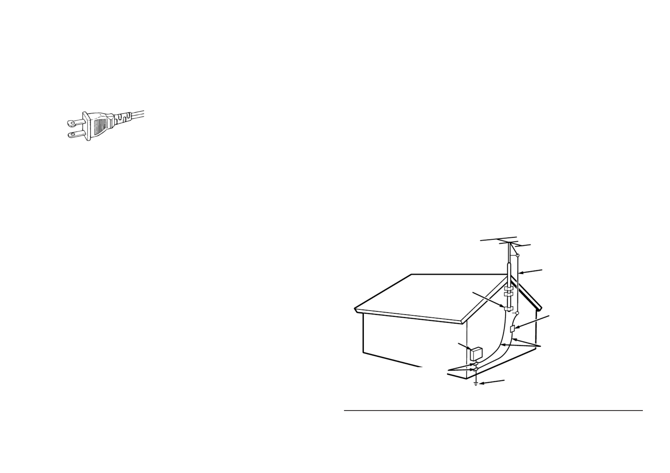
FIGURE 1
EXAMPLE OF ANTENNA GROUNDING AS PER
NATIONAL ELECTRICAL CODE, ANSI/NFPA 70
This Class B digital apparatus complies with
Canadian ICES-003.
Cet appareil num rique de la Classe B est conformeé
à la norme NMB-003 du Canada.
NEC - NATIONAL ELECTRICAL CODE
ANTENNA
LEAD IN WIRE
GROUND
CLAMP
ANTENNA
DISCHARGE UNIT
(NEC SECTION 810-20)
GROUNDING CONDUCTORS
(NEC SECTION 810-21)
ELECTRIC
SERVICE
EQUIPMENT
GROUND CLAMPS POWER SERVICE GROUNDING
ELECTRODE SYSTEM
(NEC ART 250, PART H)


ENGLISH
1
TABLE OF CONTENTS
INTRODUCTION.................................. 1
PRECAUTIONS ................................... 1
A NOTE ABOUT RECYCLING ............ 1
DESCRIPTION..................................... 2
FEATURES .......................................... 3
ACCESSORIES ................................... 3
FRONT PANEL .................................... 4
FL DISPLAY ................................................................... 5
REAR PANEL ...................................... 6
REMOTE CONTROL OPERATION ..... 7
FUNCTION AND OPERATION ...................................... 7
PROGRAMMING THE REMOTE CONTROLLER ......... 8
OPERATION OF REMOTE CONTROL UNIT ................ 9
GENERAL INFORMATION OF RC5500SR TO SR4600 ...
9
CONNECTIONS ................................. 11
SPEAKER PLACEMENT ............................................. 11
CONNECTING SPEAKERS ......................................... 11
CONNECTING AUDIO COMPONENTS ...................... 12
CONNECTING VIDEO COMPONENTS ...................... 13
ADVANCED CONNECTING ........................................ 14
CONNECTING THE REMOTE CONTROL JACKS ..... 14
CONNECTING THE ANTENNA TERMINALS .............. 15
SETUP ............................................... 16
SETUP MENU SYSTEM .............................................. 16
ENTER THE DESIRED MENU ITEM OF THE
SETUP MENU .............................................................. 16
SIMPLE SETUP ........................................................... 17
1. INPUT SETUP (ASSIGNABLE DIGITAL INPUT) ..... 17
2. SPEAKER SETUP ................................................... 18
3. PREFERENCE ......................................................... 21
4. SURROUND ............................................................ 21
5.
PL
II
(DOLBY PRO LOGIC
II
) MUSIC PARAMETER ..
22
6. CS
II
(CIRCLE SURROUND
II
) ............................... 22
BASIC OPERATION (PLAY BACK) .. 23
SELECTING AN INPUT SOURCE ............................... 23
SELECTING THE SURROUND MODE ....................... 23
ADJUSTING THE MAIN VOLUME .............................. 23
ADJUSTING THE TONE (BASS & TREBLE) CONTROL ...
23
TEMPORARILY TURNING OFF THE SOUND ............ 23
USING THE SLEEP TIMER ......................................... 23
NIGHT MODE .............................................................. 23
SURROUND MODE ........................... 24
OTHER FUNCTION ........................... 27
ATTENUATION TO ANALOG INPUT SIGNAL ............. 27
LISTENING THROUGH HEADPHONES ..................... 27
VIDEO ON/OFF ........................................................... 27
DISPLAY MODE ........................................................... 27
SELECTING ANALOG AUDIO INPUT OR DIGITAL
AUDIO INPUT .............................................................. 27
RECORDING AN ANALOG SOURCE ......................... 28
HT-EQ .......................................................................... 28
7.1 CH INPUT .............................................................. 28
7.1 CH INPUT LEVEL .................................................. 29
BASIC OPERATION (TUNER) .......... 30
LISTENING TO THE TUNER ....................................... 30
PRESET MEMORY ...................................................... 30
SURROUND SPEAKER B SYSTEM . 32
ANOTHER ROOM PLAYBACK USING THE
S(SURROUND) SPEAKER B TERMINALS ................. 32
TROUBLESHOOTING ....................... 32
TECHNICAL SPECIFICATIONS ....... 34
DIMENSIONS .................................... 34
INTRODUCTION
Thank you for purchasing the Marantz SR4600
Surround receiver.
This remarkable component has been engineered
to provide you with many years of home theater
enjoyment. Please take a few minutes to read this
manual thoroughly before you connect and operate
the SR4600.
As there are a number of connection and configuration
options, you are encouraged to discuss your own
particular home theater setup with your Marantz A/V
specialist dealer.
PRECAUTIONS
CAUTIONS ON INSTALLATION
For heat dispersal, leave at least 20 cm/8 inch of
space between the top, back and sides of this unit
and the wall or other components.
• Do not obstruct the ventilation holes.
20 cm (8 ins.)
20 cm (8 ins.)
SURROUND
AV SURROUND RECEIVER SR4600
DOWN
UP
VOLUME
INPUT SEL ECTOR
POWER ON/STANDBY P HONES
STANDBY
MUTE
7.1CH INPUT
S.SPE AKER B
ATT
PURE
SETUP
DIRECT S IMP L E
AUTO
HT-EQ
MENU
ENTER
DISPL AY
MEMO
CLEAR
T-MODE
EXIT
BAND
MODE
DISP MUL TI TUNEDAUT O ST V
–
OFF NIGHT ANALOGPEAK
DIGITAL
ATT
SLEE P SURRAUTO DIRECT DI SC 6.1 MTX 6.1 E Q
DIGITAL
SURROUND
PCM
L
C
R
SL S SR
LFE


ENGLISH
2
DESCRIPTION
DTS was introduced in 1994 to provide 5.1 channels
of discrete digital audio into home theater systems.
DTS brings you premium quality discrete multichannel
digital sound to both movies and music.
DTS is a multichannel sound system designed to
create full range digital sound reproduction.
The no compromise DTS digital process sets the
standard of quality for cinema sound by delivering
an exact copy of the studio master recordings to
neighborhood and home theaters.
Now, every moviegoer can hear the sound exactly
as the moviemaker intended.
DTS can be enjoyed in the home for either movies
or music on of DVD s, LD s, and CD’ ’ ’s.
“ ” “ ”DTS and DTS Digital Surround are registered
trademarks of Digital Theater Systems, Inc.
The advantages of discrete multichannel systems
over matrix are well known.
But even in homes equipped for discrete multichannel,
there remains a need for high-quality matrix decoding.
This is because of the large library of matrix surround
motion pictures available on disc and on VHS tape;
and analog television broadcasts.
The typical matrix decoder of today derives a
center channel and a mono surround channel from
two-channel matrix stereo material. It is better than
a simple matrix in that it includes steering logic to
improve separation, but because of its mono,
band-limited surround it can be disappointing to
users accustomed to discrete multichannel.
Neo:6 offers several important improvements as
follow,
•Neo:6 provides up to six full-band channels of
matrix decoding from stereo matrix material.
Users with 6.1 and 5.1 systems will derive six
and five separate channels, respectively,
corresponding to the standard home-theater
speaker layouts.
•
Neo:6 technology allows various sound elements
within a channel or channels to be steered
separately, and in a way which follows naturally
from the original presentation.
•
Neo:6 offers a music mode to expand stereo
nonmatrix recordings into the five- or six-channel
layout, in a way which does not diminish the subtlety
and integrity of the original stereo recording.
DTS-ES Extended Surround is a new multichannel
digital signal format developed by Digital Theater
Systems Inc. While offering high compatibility with
the conventional DTS Digital Surround format,
DTS-ES Extended Surround greatly improves the
360-degree surround impression and space
expression thanks to further expanded surround
signals. This format has been used professionally
in movie theaters since 1999.
In addition to the 5.1 surround channels (FL, FR,
C, SL, SR and LFE), DTS-ES Extended Surround
also offers the SB (Surround Back) channel for
surround playback with a total of 6.1 channels.
DTS-ES Extended Surround includes two signal
formats with different surround signal recording
methods, as DTS-ES Discrete 6.1 and DTS-ES
Matrix 6.1.
“ ” “ ” “ ”DTS , DTS-ES and Neo:6 are trademarks of
Digital Theater Systems, Inc.
The stereo CD is a 16-bit medium with sampling at
44.1 kHz. Professional audio has been 20- or 24-
bit for some time, and there is increasing interest in
higher sampling rates both for recording and for
delivery into the home. Greater bit depths provide
extended dynamic range. Higher sampling rates
allow wider frequency response and the use of
anti-alias and reconstruction filters with more
favorable aural characteristics.
DTS 96/24 allows for 5.1channel sound tracks to
be encoded at a rate of 96kHz/24bits on DVD-
Video titles.
When DVD-video appeared, it became possible to
deliver 24-bit, 96 kHz audio into the home, but only
in two channels, and with serious limitations on
picture. This capability has had little use.
DVD-audio allows 96/24 in six channels, but a new
player is needed, and only analog outputs are
provided, necessitating the use of the D/A converters
and analog electronics provided in the player.
DTS 96/24 offers the following:
1. Sound quality transparent to the original 96/24
master.
2.
Full backward compatibility with all existing
decoders. (Existing decoders will output a 48 kHz
signal)
3. No new player required: DTS 96/24 can be
carried on DVD-video, or in the video zone of
DVD-audio, accessible to all DVD players.
4. 96/24 5.1-channel sound with full-quality full-
motion video, for music programs and motion
picture soundtracks on DVD-video.
“ ” “ ”DTS and DTS 96/24 are trademarks of Digital
Theater Systems, Inc.
Dolby Digital identifies the use of Dolby Digital
audio coding for such consumer formats as DVD
and DTV. As with film sound, Dolby Digital can
provide up to five full-range channels for left,
center, and right screen channels, independent left
and right surround channels, and a sixth ( ".1")
channel for low-frequency effects.
Dolby Surround Pro Logic is an improved matrixII
decoding technology that provides better spatiality
and directionality on Dolby Surround program
material; provides a convincing three-dimensional
soundfield on conventional stereo music recordings;
and is ideally suited to bring the surround experience
to automotive sound. While conventional surround
programming is fully compatible with Dolby Surround
Pro Logic decoders, soundtracks will be able to beII
encoded specifically to take full advantage of Pro
Logic II playback, including separate left and right
su r rou nd ch an ne l s. (Such mate rial i s als o
compatible with conventional Pro Logic decoders.)
Dolby Digital EX creates six full-bandwidth output
channels from 5.1-channel sources. This is done
using a matrix decoder that drives three surround
channels from the two in the original recording.
For best results, Dolby Digital EX should be used
with movies soundtracks recorded with Dolby
Digital Surround EX.
About Dolby Pro Logic
IIx
Dolby Pro Logic x technology delivers a naturalII
and immersing 7.1-channel listening experience to
the home theater environment. A product of
Dolby's expertise in surround sound and matrix
decoding technologies, Dolby Pro Logic x is aII
complete surround sound solution that maximizes
the entertainment experience from stereo as well
as 5.1-channel encoded sources.
Dolby Pro Logic x is fully compatible with DolbyII
Surround Pro Logic technology and can optimally
decode the thousands of commercially available Dolby
Surround encoded video cassettes and television
programs with enhanced depth and spatiality. It can
also process any high-quality stereo or Advanced
Resolution 5.1-channel music content into a seamless
6.1- or 7.1-channel listening experience.
Manufactured under license from Dolby Laboratories.
“ ” “ ”Dolby , Pro Logic , and the double-D symbol are
trademarks of Dolby Laboratories.
Circle Surround (CS-II II) is a powerful and versatile
multichannel technology. CS- is designed toII
enable up to 6.1 multichannel surround sound
playback from mono, stereo, CS encoded sources
and other matrix encoded sources. In all cases the
decoder extends it into 6 channels of surround
audio and a LFE/subwoofer signal. The CS- II
decoder creates a listening environment that
places the listener music performances“inside”
and dramatically improves both hi- fi audio
conventional surround-encoded video material.
CS-II provides composite stereo rear channels to
greatly improve separation and image positioning –
adding a heightened sense of realism to both audio
and A/V productions.
CS-II is packed with other useful feature like dialog
clarity (SRS Dialog) for movies and cinema-like
bass enrichment (TruBass). CS-II can enable the
dialog to become clearer and more discernable in
movies and it enables the bass frequencies
contained in the original programming to more
closely achieve low frequencies – overcoming the
low frequency limitations of the speakers by full
octave.
Circle Surround II, Dialog Clarity, TruBass, SRS
and symbol are trademarks of SRS Labs, Inc.
Circle Surround II, Dialog Clarity and TruBass
technology are incorporated under license from
SRS Labs, Inc.


ENGLISH
3
FEATURES
The SR4600 incorporates the latest generation of
digital surround sound decoding technology such
as Dolby Digital EX, Dolby Digital, DTS ES
(Discrete 6.1 and Matrix 6.1), DTS Neo:6 (Cinema,
Music), Dolby Pro-Logic x (Movie, Music andII
Game), Circle Surround (Cinema and Music).II
In addition, Marantz has focused on the future. By
utilizing pre-out jacks, 7.1 direct inputs the SR4600
is tomorrow's technology, today!
The SR4600 features a fully discrete 7 channel
amplifier section capable of delivering 80 watts of
high-current amplification, for continuously clean and
stable power into each of the seven channels. It
employs a massive EI power transformer in
combination with oversized filter capacitors. This
design configuration is capable of a clear and
powerful reproduction of the most demanding action
movie soundtracks and full range (multichannel)
music discs. Through its ability to generate very high
output voltages, the SR4600 can easily drive the
most demanding speakers with optimum results.
The SR4600 incorporates the most advanced
Digital Signal Processing circuitry, along with a
Crystal® 192 kHz/24 bit D/A converter in each of
the 7 channels. Independent power supply circuits
are incorporated for the FL display, audio and
video sections for maximum separation, clarity and
dynamic range. Together with hand-selected
customized components, all elements work in
harmony to recreate the emotion, exactly as the
artist had intended.
The SR4600 is designed and engineered with
extensive feedback from dealers and consumers. It
features a heavy duty speaker binding posts and
an extensive array of both analog and digital inputs
/ outputs. With 4 assignable digital inputs, 2
component inputs and SACD Multi Channel (7.1
channel) direct inputs is taken to a stunning new
level.
An easy-to-use universal remote control allows full
access to all of the operating functions and can be
used for system operation as well.
This unit has Simple Setup function for easy setup.
You can setup all speaker settings by just selecting
your room size and the number of your speakers
with Simple Setup function. You can also setup
customized settings just like conventional AV
amplifiers.
The TruSurround Headphone technology provides
a surround sound listening experience over
headphones.
When listening to multichannel content such as DVD
movies over headphones, the listening experience is
fundamentally different than listening to speakers.
Since the headphone speaker drivers are covering the
pinna of the ear, the listening experience differs greatly
from traditional speaker playback. TruSurround utilizes
patented headphone perspective curves to solve this
problem and provides a non-fatiguing, immersive,
home theater listening experience. TruSurround
Headphone also delivers exceptional 3D audio from
mono and stereo material.
•Dolby Digital EX, Dolby Digital ,
DTS ES (Discrete 6.1, Matrix 6.1, Neo: 6)
•Dolby Pro Logic
II
x
(Movie, Music, Game)
•Circle Surround
II
(Movie, Music, Mono)
•HDCD decording
•7 x 80 Watts (8 Ohm), Discrete Amplifiers
•Massive Energy Power Supply, Huge EI
Transformer, Large ELCO's.
•192 kHz/24 bit Crystal® DAC for all 7 Channels
•32 bit Digital Surround Processing Chipsets
•Video Off Mode
•Large Heavy Duty Speaker Terminals for all
Channels
•Auto Input Signal Detection
•Improved Station Name Input Method, 50
Presets
•Auto Adjust Function for Speaker Distance
Settings (Delay Time)
•Universal remote control
•Simple Setup Function
•Simple Video Conversion (Video ↔ S-Video)
ACCESSORIES
Remote Controller RC5500SR
CH.SEL LIP.S YNC
PT Y
SUB-T /AT T
AUDIO
INPUT /DI SC+
F.DIRECT
RDS
T UNE/SEARCH
T -M ODE
T REBLE
CHANNEL/SKIP
BASS
A/D
P.SCAN/V- OFF
7.1CH IN
ST EREO
MCH-ST
MEM O
CLEAR
DIS PLAY
NIGH
T
CSII EX/ES VIRT UAL
DT S
S-D IRECT
AUT O
T .T ONE
MENU OFF
SET UP/
MENU
OSD
SLEEP
MUT E
AMP
AUX1
T UNER
CD
T APE
CDR/MD
DVD
POWER
VCR1
DSS /VCR2
T V
SYS
T EM REMO T E CO
NT
ROLL ER
RC5500 SR
ENT ER
0
321
654
9
8
7
VOL.
MAIN
VOL.
T V
AAA-size batteries X 2
AM Loop Antenna
FM Antenna
AC Cable
User Guide
HDCD® (High Definition Compatible Digital
®) is a
patented process for delivering on Compact Disc
the full richness and details of the original
microphone feed.
HDCD encoded CDs sound better because they
are e nco ded with 2 0- b its o f real musi cal
information as compared to 16-bits for all other
CDs.
HDCD overcomes the limitation of the 16-bit CD
format by using a sophisticated system to encode
the additional four bits onto the CD while remaining
completely compatible with the CD format.
When listening to HDCD recordings, you hear
more dynamic range, a focused 3-D sound stage,
and extremely natural vocal and musical timbre.
With HDCD, you get the body, depth and emotion
of the original performance not a flat, digital
imitation.
HDCD system manufactured under license from
Microsoft. This product is covered by one or more
of the following: In the United States 5,479,168
5,638,074 5,640,161 5,808,574 5,838,274
5,854,600 5,864,311 5,872,531 and in Australia
669,114 with other patents pending.


ENGLISH
4
FRONT PANEL
t
INFRARED receiving sensor window
This window receives infrared signals for the remote
control.
y
SURROUND MODE button
You can select the surround mode by pressing this
button.
u
PURE DIRECT button
When this button is pressed, the tone control circuitry
is bypassed as well as Bass Management.
DIRECT indicator will be illuminated in the display.
Notes:
•
The surround mode is automatically switched to
AUTO when the pure direct function is turned on.
• Additionally, Speaker Configurations are fixed
automatically as follows.
Front SPKR = Large, Center SPKR = Large,
Surround SPKR = Large, Sub woofer = On
•
This function is unavailable when the surround
speaker B system is activated. While this
function
is
activated, this
function will be canceled if
the S.
SPEAKER B button is pressed.
SURROUND
AV SURROUND RECEIVER SR4600
DO WN
UP
VO LUME
INPUT SELECT OR
PO WER ON/ST ANDBY PHONES
ST ANDBY
MUT E
7.1CH INPUT
S. SPEAKER B
AT T
PURE
SET UP
DIRECT
SIMPLE
AUTO
HT - EQ
MENU
ENT ER
DISPLAY
MEMO RY
CLEAR
T - MO D E
EXIT
BAND
MO DE
DISP T UNED STMULT I AUT O V
–
O FF NIGHT PEAK ANALO G
DIGIT AL
ATT
SLEEP SURRAUT O DIREC T MT X 6.1 EQDISC 6.1
DIGIT AL
SURR OUND
PC M
L
C
R
SL S S R
LFE
!5!6!7!8!9@0@1@2
q w y u !3i o !0t !2!1re
!4
q
POWER switch and STANDBY indicator
When this switch is pressed once, the unit turns ON
and the display illuminates. When pressed again,
the unit turns OFF and the STANDBY indicator will
be illuminated.
w
7.1CH INPUT button
Press this button to select the output of an external
multichannel player.
e
INPUT SELECTOR knob (AUDIO/ VIDEO)
This knob is used to select the input sources.
The video function selector, such as TV, DVD, VCR1
and DSS, selects video and audio simultaneously.
Audio function sources such as CD, TAPE, CDR/
MD, and TUNER may be selected in conjunction
with a Video source.
This feature (Sound Injection) combines a sound
from one source with a picture from another.
Choose the video source first, and then choose a
different audio source to activate this function.
r
S.(Surround) SPEAKER B button
Press this button to activate the Surround Speaker
B system . indicator will be illuminated in“SPKR B”
the display.
(See page 32)
i
SIMPLE SETUP button
Press this button to enter the simple setup mode.
You can setup the speaker conditions (speaker
sizes, number of speakers, speaker delay times)
quickly by pressing the cursor buttons.
o
DISPLAY button
When this button is pressed, the FL display mode
is changed as Surround Mode → Auto-display Off
→ → Display Off Input Function and the display off
indicator(DISP) lights up in condition of DISPLAY
OFF.
!0
MEMORY button
Press this button to enter the tuner preset memory
numbers or station names. (See page 30)
!1
CLEAR button
Press this button to cancel the station-memory setting
mode or preset scan tuning. (See page 31)
!2
VOLUME control knob
Adjusts the overall sound level. Turning the control
clockwise increases the sound level.
!3
ATT (Attenuate) button
If the selected analog audio input signal is greater
than the capable level of internal processing, the
PEAK indicator will illuminate. If this happens, you
should press the ATT button. is displayed“ ”ATT
when this function is activated.
The signal-input level is reduced by about half.
Attenuation will not work with the output signal of
“ ”REC OUT (TAPE, CD-R/MD, VCR1 and VCR2
output). This function is memorized for each input
function.
!4
MUTE button
Press this button to mute the output to the speakers.
Press it again to return to the previous volume level.
!5
T-MODE button
Press this button to select the auto stereo mode or
mono mode when the FM band is selected.
The “AUTO” indicator lights in the auto stereo mode.
(See page 30)
!6
BAND button
Press this button to switch between FM and AM in
the TUNER mode.
!7
EXIT button
This button is used to exit from the SETUP MAIN
MENU.
!8
Cursor ( ) / ENTER button, , ,
Use these buttons when operating the SETUP MAIN
MENU and TUNER function.
!9
MENU button
This button is used to enter the SETUP MAIN MANU.
@0
HT-EQ button
Used to turn on or off HT(Home Theater)-EQ mode.
This mode compensates for the audio portion of a
movie sounding . When this button is“bright”
pressed, EQ“ ” indicator lights up.
@1
AUTO (Auto surround) button
Press this button to select the AUTO mode from the
surround modes. When this mode is selected, the
receiver determines the surround mode corresponding
to a digital input signal automatically.
@2
HEADPHONE jack for stereo headphones
This jack may be used to listen to the SR4600’s
output through a pair of headphones. Be certain
that the headphones have a standard 1 / 4" stereo
phono plug. Note that the main room speakers will
automatically be turned off when the headphone
jack is in use.
Notes:
• When using headphones, the surround mode will
change to STEREO and TruSurround (TS)
headphones by SURROUND MODE button.
•
The surround mode returns to the previous setting
as soon as the headphone plug is removed from the
jack.


ENGLISH
5
DISP TUNED ST V AUTO
–
OFF NIGHT PEAK ANALOG
DIGITAL
ATT
SLEEP SURRAUTO DIRECT MT X 6.1 EQDISC 6.1
DIGITAL
SURROUND
PCM
L
C
R
SL S SR
LFE
SPKR B
¡7
¡6
f
s
a
¡5¡8
gj l
¡1 ¡3d h ¡0 ¡2 ¡4k
FL DISPLAY
a
DISP (Display Off) indicator
This indicator is illuminated when the SR4600 is in
the display off condition.
s
SLEEP timer indicator
This indicator is illuminated when the sleep timer
function is active.
d
AUTO SURR (Auto Surround mode)
indicator
This indicator is illuminated to show that the AUTO
SURROUND mode is in use.
f
TUNER’s indicators
AUTO : This indicator illuminates when the
tuner’s Auto mode is in use.
TUNED : This indicator illuminates when a
station is being received with
sufficient signal strength to provide
acceptable listening quality.
ST(Stereo) :
This indicator illuminates when an
FM station is being tuned into stereo
condition.
g
DTS-ES mode indicators (DISC6.1, MTX6.1)
These indicators will illuminate to show the DTS-
ES decoding mode (Discrete 6.1 or Matrix 6.1).
h
V (video)-OFF mode indicator
This indicator is illuminated when the Video-OFF
function is active.
¡4
SIGNAL FORMAT indicators
2 2 DIGITAL, EX, SURROUND, dts, ES, 96/24,
PCM
When the selected input is a digital source, some
of these indicators will be illuminated to display the
specific type of signal in use.
¡5
ENCODED CHANNEL STATUS
indicators
These indicators display the channels that are
encoded with a digital
input signal. If the selected digital input signal is
Dolby Digital 5.1ch or DTS 5.1ch, “ ”L , , “ ”C“ ”R ,
“ ” “ ” “ ”SL , SR and LFE will be illuminated. If the
digital input signal is 2 channel PCM-audio, and“ ”L
“ ”R will be displayed.
If Dolby Digital 5.1ch signal with Surround EX flag
or DTS-ES signal comes in, “ ”L , , , SL , “ ”C“ ”R“ ” “ ”S ,
“ ” “ ”SR and LFE will be illuminated.
¡6
Main Information Display
This display shows messages relating to the
status, input source, surround mode, tuner,
volume level or other aspects of unit s operation.’
¡7
DIRECT (Pure direct) indicator
This indicator is illuminated when the SR4600 is in
the PURE DIRECT mode.
¡8
HDCD indicator
When HDCD signal is decoded from digital input,
this indicator will light up.
j
NIGHT mode indicator
This indicator is illuminated when the SR4600 is in
the Night mode, which reduces the dynamic range
of digital program material at low volume levels.
k
SPKR (Speaker) B indicator
This indicator is illuminated when the S(Surround)
speaker B system is active.
l
PEAK indicator
This indicator is a monitor for an analog audio input
signal. If the selected analog audio input signal is
greater than the capable level of internal processing,
this will illuminate. If this happens, you should press
the ATT button on the front panel or the remote.
¡0
EQ mode indicator
This indicator is illuminated when the HT-EQ
function is active.
¡1
ATT (Attenuation) indicator
This indicator is illuminated when the attenuation
function is active.
¡2
DIGITAL Input Indicator
This indicator lights when a digital input has been
selected.
¡3
ANALOG input indicator
This indicator is illuminated when an analog input
source has been selected.

ENGLISH
6
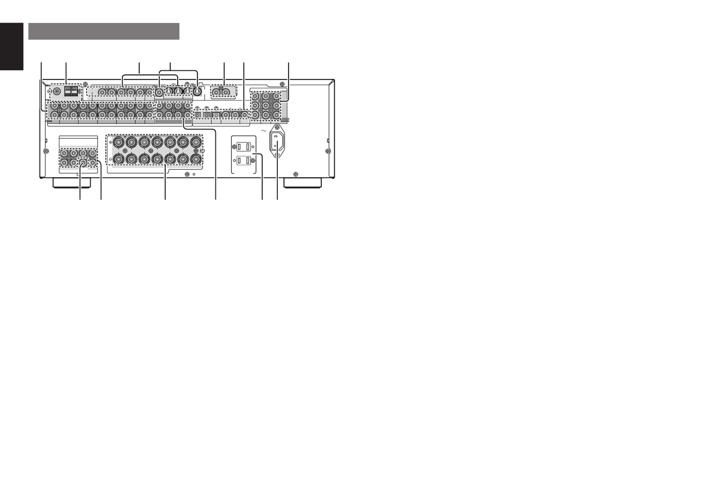
n
DIGITAL INPUT (Dig.1 - 4) / OUTPUT
(coaxial, optical)
These are the digital audio inputs and outputs.
There are 2 digital inputs with coaxial jacks, 2 with
optical jacks.
The inputs accept digital audio signals from a
compact disc, LD, DVD, or other digital source
component.
For digital output, there is 1 coaxial output and 1
optical output.
The digital outputs can be connected to MD
recorders, CD recorders, DAT decks, or other
similar components.
m
COMPONENT VIDEO INPUT/OUTPUT
If your DVD player or other device has component
video connectors, be sure to connect them to these
component video connectors on the SR4600. The
SR4600 has two component video input connectors
to obtain the color information (Y, C
B
, C
R
) directly
from the recorded DVD signal or other video
component and one component video output
connector to output it directly into the matrix decoder
of the display device.
By sending the pure DVD component video signal
directly, the DVD signal forgoes the extra
processing that normally would degrade the image.
The result is vastly increased image quality, with
incredibly life like colors and crisp detail.
,
AC INLET
Plug the supplied power cord into this AC INLET
and then into the power outlet on the wall.
SR4600 can be powered by 120V AC only.
.
AC OUTLETS
Connect the AC power cables of components such as
a DVD and CD player to these outlets. SWITCHED
and UNSWITCHED outlets are provided.
The one marked SWITCHED provides power only
when the SR4600 is turned on and is useful for
components which you use every time you play
your system.
The one marked UNSWITCHED is always live as
long as the SR4600 is plugged into a live outlet.
A component connected here may be left on
permanently, or may be switched off with via its
own power switch.
Caution:
•
In order to avoid potential turn-off thumps, anything
plugged into these outlets should be powered up
before the SR4600 is turned on.
REAR PANEL
c
VIDEO IN/OUT (TV, DVD, VCR1, DSS/VCR2)
These are the video inputs and outputs. There are
4 video inputs and 2 video outputs and each one
includes both composite video and S-video
configurations. Connect VCRs, DVD players, and
other video components to the video inputs.
The 2 video output channels can be used to be
connected to video tape recorders for making
recordings.
The input signals of video and S-video are converted
each other, and each of the converted video signals
can be output.
v
MONITOR OUT
This is a monitor output and each one includes both
composite video and S-video configurations.
b
REMOTE CONT. IN/OUT terminals
Connect to a Marantz component equipped with
remote control (RC-5) terminals.
z
AUDIO IN/OUT (CD, TAPE, CD-R/MD, TV,
DVD, VCR1, DSS/VCR2)
These are the analog audio inputs and outputs.
There are 7 audio inputs (4 of which are linked to
video inputs) and 4 audio outputs (2 of which are
linked to video outputs). The audio jacks are
nominally labeled for cassette tape decks,
compact disc players, DVD players and etc.... The
audio inputs and outputs require RCA-type
connectors.
x
FM antenna terminal (75 ohms)
Connect an external FM antenna with a coaxial
cable, or a cable network FM source.
AM antenna and ground terminals
Connect the supplied AM loop antenna. Use the
terminals marked and . The supplied“AM” “GND”
AM loop antenna will provide good AM reception in
most areas. Position the loop antenna until you
hear the best reception.
•
The capacity of this AC outlet is 100W. Do not
connect devices that consume electricity more than
the capacity of these AC outlets. If the total power
consumption of the connected devices exceeds the
capacity, the protection circuit shuts down the
power supply.
⁄0
7.1 CHANNEL INPUT
By connecting a DVD Audio player, SACD
multichannel player, or other components that
has a multichannel port, you can playback the
audio with 5.1 channel or 7.1 channel outputs.
⁄1
Speaker outputs terminals
Seven terminals are provided for the front left, front
right, front center, surround left, surround right,
surround back left and surround back right speakers.
Note:
•You can use surround back speaker terminals as
S(Surround) SPEAKER B terminals, when you
use no surround back speaker.
⁄2
Preamp Outputs
(L, R, SL, SR, SBL, SBR, C)
Jacks for L(front left), R (front right), C (Center), SL
(surround left), SR (surround right), SBL (surround
back left) and SBR (surround back right).
Use these jacks for connection to external power
amplifiers.
⁄3
Subwoofer Output
Connect this jack to the line level input of a powered
subwoofer. If an external subwoofer amplifier is used,
connect this jack to the subwoofer amplifier input. If
you are using two subwoofers, either powered or with
a 2 channel subwoofer amplifier, connect a “ ”Y
connector to the subwoofer output jack and run one
cable from it to each subwoofer amplifier.
IN OUT
MONITOR
VCR1
MONITOR
R SR
C
SW SBR
SL SBLL
R
SPEAKER SYSTEMS MINIMUM 6 OHMS
CENT ER
R
FRONT SURROUND BACK
S. SPEAKER B
SURROUND
L LLR
DVD
OUT
IN
MONITOR
T VDVDVCR1
OUTIN
DSS
/
VCR2
OUT
VIDEO
IN
Y
DSS
/
VCR
2
DVD
COAX.
OUT
43OPT.
OUT
21
7.1CH INPUT
L SL C SBL
SBRSWSRR
T VDVDVCR1
OUTININ OUT
DSS
/
VCR2
IN OUT
CDR/MDT APE
PRE OUT
OUTIN
CD
R
L
FM (75
Ω
) GND AM
CB
/
PB
CR
/
PR
AUDIO
ANTENNA
RC-5
DIGIT AL
COMPONENT VIDEO
AUDIO
S-
VIDEO
AC OUTLETS
120V 60HZ
1A 120 W MAX
UNSWITCHED
SWIT CHED
1A 120 W MAX
AC IN
c
.⁄3
v b n m
⁄1 ,⁄0⁄2
z x


ENGLISH
7
m
Cursor ( ) / OK buttons, , ,
(when AMP mode is selected)
Use these button when operating the SETUP MAIN
MENU.
,
MENU OFF button
(when AMP mode is selected)
This button is used to exit from the SETUP MAIN
MENU.
.
Numeric buttons 1 to 9 / Surround mode
buttons
Numeric buttons
These buttons are used to enter figures in the selec-
tion of a tuner preset station and station name pre-
set or to set select a CD track number, etc. The func-
tions of these buttons are dependent on the function
button selected.
Surround mode buttons
(when AMP mode is selected)
These buttons are used to select the surround mode.
⁄0
P.SCAN (Preset scan) / V(Video)-OFF
button
(when TUNER mode is selected)
This button is used to start preset scan when SR4600
is selected TUNER mode.
(when AMP mode is selected)
This is used when switching the video signals from
the various monitor outputs to Video-Off mode.
⁄1
0 / A/D button
0 button
This button is used to enter the number “ ”0
A/D button (when AMP mode is selected)
This is used to switch between the analog and digital
inputs.
⁄2
CONTROL buttons
These buttons are used when operating the CD
player, TAPE deck, etc.
The function of these buttons are dependent on the
function button selected.
For the controllable functions of each input function,
please refer to controllable function table on the page
10.
⁄3
SUB-T (Title) / ATT (attenuator) button
When the input signal is too high and the voice dis-
torts even while adjusting the SR4600 VOLUME
control, turn on this function. “ ”ATT is illuminated
when this function is activated.
The input level is reduced. Attenuator is invalid for
the output signal of REC OUT“ ”.
Note:
•
This function is unavailable while the digital input
is selected.
⁄4
INPUT/DISC+ / CH.SEL buttons
This button is used to enter the input level setup
menu.
⁄5
TREBLE UP ( ) /DOWN ( ) buttons
These buttons are used to adjust the tone control of
high frequency sound for left and right speaker.
⁄6
BASS UP ( ) /DOWN ( ) buttons
These buttons are used to adjust the tone control of
low frequency sound for left, right and subwoofer
speaker.
⁄7
MEMO button
Memory enable button for various preset functions.
⁄8
CLEAR button
This button is used to cancel for certain memory or
programming operations.
⁄9
DISPLAY button
Selects the display mode for the front display of the
SR4600.
¤0
NIGHT button
Pressing this button prevents the Dolby Digital sig-
nal from playback at a loud voice. This function re-
duces the voice by 1/3 to 1/4 at maximum. Thus, it
eliminates the occurrence of an abruptly loud voice
at night. However, the function is valid only in the
case when the Dolby Digital signal is entered into
OPTICAL or COAXIAL and data to compress the
voice exists in the signal to be played back.
When this button is pressed, the indicator“NIGHT”
is illuminated.
REMOTE CONTROL
OPERATION
FUNCTION AND OPERATION
The provided remote control unit is a universal re-
mote controller. The POWER button, numeric but-
tons and control buttons are used in common across
different input source components.
The input source controlled with the remote control
unit changes when one of the input selector but-
tons is pressed.
z
Transmitting indicator
Lights up during a button is pressed and an infrared
signal is sending.
x
(Main) POWER buttons
(when AMP mode is selected)
Press to switch the power of the SR4600 ON or OFF
after pressing the AMP button.
c
Input selector buttons/ FUNCTION
SELECTOR buttons (AUDIO/VIDEO INPUT)
These buttons are used to select a Audio or Video
source component. Press one of these buttons once
to change the function of the remote control. Press
same button within 2 seconds, the input function of
the SR4600 is changed.
Audio function sources such as CD, TAPE, CDR/
MD, and TUNER may be selected in conjunction
with a Video source.
This feature (Sound Injection) combines a sound
from one source with a picture from another.
Choose the video source first, and then choose a
different audio source to activate this function.
Notes:
•CDR/MD button is set CDR function at initial. To
switch MD function, press and hold down CDR/
MD button and press 2 button.
•To return CDR function, press and hold down
CDR/MD button and press 1 button.
v
MAIN VOLUME UP ( ) /DOWN ( ) buttons
Main volume control of the SR4600. The front, sur-
round, center and subwoofer channel volumes con-
trolled by these buttons simultaneously.
b
MUTE button
Muting button of the SR4600. Press this button de-
crease the sound temporarily. Press this button
again to return to the previous sound.
When this button is pressed, indicator lights“MUTE”
up.
n
MENU button
(when AMP mode is selected)
This button is used to enter the SETUP MAIN MENU.
ENTER
CH.SEL LIP.SYNC
PTY
SUB-T/AT T
AUDIO
INPUT/DISC+
F.DIRECT
RDS
TUNE/SEARCH
T-MODE
TREBLE
CHANNEL/SKIP
BASS
A/D
P.SCAN/V-OFF
7.1CH IN
STEREO
MCH-ST
MEMO
CLEAR
DISPLAY
NIGHT
CSII EX/ES VIRTUAL
DTS
PURE DIRECT
AUTO
321
654
98
0
7
T.TONE
MENU OFF
SET UP/
MENU
OSD
VOL.
TV
VOL.
MAIN
SLEEP
MUT E
AMPAUX1
TUNER
CD
TAPE
CDR/MD
DVD
POWER
VCR1
DSS/VCR2
TV
SYSTEM REMOTE CONTROLLER
RC5500SR
,
m
n
b
v
c
x
z
⁄1
⁄2
⁄5
¤3
¤2
¤1
¤0
⁄9
⁄8
⁄7
⁄6
¤4
⁄4 ⁄3
¤5
.
⁄0


ENGLISH
8
RESETTING THE ALL CODE
1.
Press and hold down the any Function
Selector SETUP button and press button
until the indicator blinking twice.
2.
Press the code 9 8 - - 1.
The indicator will blink twice.
Then, RC5500SR will return to the factory
preset code.
Note:
•After this procedure, the selected function button
is set initial code and other function buttons are
set initial code too.
Once you have found and the codes for your vari-
ous appliances, you may want to write them down
here.
TV
VCR
DSS
DVD
CD
TAPE
CDR
MD
SCANNING THE CODE TABLE
1.
Switch on the appliance which should be
controlled.
2.
Press and hold down the Function Selector
button for appliance which should be controlled
and press until the indicatorSETUP button
blinking twice.
3.
Press the code 9 9 - - 1.
The indicator will blink twice.
4.
Aim the remote control at the appliance and
slowly alternate between pressing POWER
button and the
Function Selector
button for
the appliance.
5.
Stop when the appliance turns off.
6.
Press SETUP button once to lock in the code.
CHECKING THE CODE
1.
Press and hold down the Function Selector
button for appliance which should be controlled
and press button until the indicatorSETUP
blinking twice.
2.
Press the code 9 9 - - 0.
The indicator will blink twice.
3.
To view the code for first digit, press 1 once.
Wait 3 seconds, count the indicator blinks
(e.g. 3 blinks = 3) and write down the number.
Note:
If a code digit is , the indicator will not blink.“ ”0
4.
Repeat step 3 three more times for remaining
digits. Use for the second digit, for the2 3
third digit, and for the fourth digit.4
PROGRAMMING THE REMOTE CONTROLLER
The remote controller RC5500SR must be
programmed to use the codes for your appliances
of different brands. This is done by keying in a 4-
digit code or by scanning the codes until the correct
one is found. We recommend to using the 4-digit
code. This mode is faster and more reliable. The
code scanning method should be used only if you
cannot find the code for one of your appliances.
The codes are listed at the end of this book.
Important:
•
Use the remote control buttons for programming,
not the buttons of the receiver or other appliances.
•
Some codes may be not match your equipment.
In this case, your equipment cannot be controlled
with this remote controller.
PROGRAMMING WITH THE 4-DIGIT CODE
1.
Press and hold down the Function Selector
button for the appliance which should be
controlled and press until theSETUP button
indicator blinks twice.
2.
Press the 4-digit code for appliance (code
table at the end of this book)
3.
When the procedure is successful, the indicator
will blink twice.
Note:
•If the indicator did not blink twice, then repeat
steps 1 through 2 and try entering the same code
again.
MENU
OSD
VOL.
TV
VOL.
MAIN
SLEEP
MUTE
AMPAUX1
TUNER
CD
TAPE
CDR/MD
DVD
POWER
VCR1
DSS/VCR2
TV
1.
ENTER
PTY
SUB-T/ATT
AUDIO
INPUT/DISC+
F.DIRECT
RDS
TUNE/SEARCH
T-MODE
TREBLE
CHANNEL/SKIP
BASS
A/D
P.SCAN/V-OFF
7.1CH IN
ST EREO
MCH-ST
MEMO
CLEAR
DISPLAY
NIGHT
CSII EX/ES VIRTUAL
DTS
PURE DIRECT
AUTO
321
654
98
0
7
T.TONE
MENU OFF
SET UP/
1.
2.
MENU
OSD
VOL.
TV
VOL.
MAIN
SLEEP
MUTE
AMP
TUNER
CD
TAPE
CDR/MD
DVD
POWER
VCR1
DSS/VCR2
TV
AUX1
1.
ENTER
TUNE/SEARCH
TREBLE
CHANNEL/SKIP
BASS
A/D
P.SCAN/V-OFF
7.1CH IN
ST EREO
MCH-ST
MEMO
CLEAR
DISPLAY
NIGHT
CSII EX/ES VIRTUAL
DTS
PURE DIRECT
AUTO
321
654
98
0
7
T.TONE
MENU OFF
SET UP/
MENU
OSD
1.
2.
MENU
OSD
VOL.
TV
VOL.
MAIN
SLEEP
MUTE
AMP
TUNER
CD
TAPE
CDR/MD
DVD
POWER
VCR1
DSS/VCR2
TV
AUX1
2.
4.
4.
ENTER
TUNE/SEARCH
TREBLE
CHANNEL/SKIP
BASS
A/D
P.SCAN/V-OFF
7.1CH IN
ST EREO
MCH-ST
MEMO
CLEAR
DISPLAY
NIGHT
CSII EX/ES VIRTUAL
DTS
PURE DIRECT
AUTO
321
654
98
0
7
T.TONE
MENU OFF
SET UP/
2.
6.
3.
MENU
OSD
VOL.
TV
VOL.
MAIN
SLEEP
MUTE
AMP
TUNER
CD
TAPE
CDR/MD
DVD
POWER
VCR1
DSS/VCR2
TV
AUX1
1.
ENTER
F.DIRECT
RDS
TUNE/SEARCH
T-MODE
TREBLE
CHANNEL/SKIP
BASS
A/D
P.SCAN/V-OFF
7.1CH IN
ST EREO
MCH-ST
MEMO
CLEAR
DISPLAY
NIGHT
CSII EX/ES VIRTUAL
DTS
PURE DIRECT
AUTO
321
654
98
0
7
T.TONE
MENU OFF
SET UP/
1.
3.
4.
2.
¤1
PURE DIRECT button
When this button is pressed, the tone control circuit
is bypassed.
¤2
SETUP / T.TONE button
(when AMP mode is selected)
Used to enter the test tone menu.
¤3
OSD button
Note:
•This button is unavailable for SR4600.
¤4
SLEEP (sleep timer) button
This button is used for setting the sleep timer. It can
be operated the same way as the button on the unit.
¤5
TV VOLUME UP ( ) /DOWN ( ) buttons
These buttons increase or decrease TV’s volume.


ENGLISH
9
OPERATION OF REMOTE CONTROL UNIT
REMOTE CONTROL
The distance between the transmitter of the remote
control and the IR SENSOR of the SR4600 should
be less than 5 meters. If the remote control is pointed
in a direction other than the IR SENSOR or if there is
an obstacle between them, use of the remote control
may not be possible.
Remote-controllable range
LOADING BATTERIES
The life of the batteries used with the remote control
is about 4 months with normal use. Also be sure to
replace batteries earlier when you notice that they
are getting weak.
1.
Remove the back cover.
2.
Insert the new batteries (AAA type) with
correct and polarity.
3.
Close the cover until it clicks.
POWER Turns the SR4600 on and off
Function selector *
Selects a particular source component
SLEEP * Sets the sleep timer function
MUTE * Decreases the sound temporarily
VOL
34
* Adjusts the over all sound level
MENU Enters the SETUP MENU
Cursor Moves the cursor for settings in the SETUP MENU
ENTER • Enters the SETUP MENU
• Confirms the settings in SETUP MENU
SETUP/T.TONE Enters the test tone mode for setting the Speaker Level Setup
MENU OFF Exits from the SETUP MENU
PURE DIRECT * Selects the Pure Direct mode
NIGHT * Turns on or off the NIGHT mode
DISPLAY * Change the front display mode
Surround mode (1-8)
Selects the surround mode
7.1CH-IN (9) Selects the 7.1CH IN
A/D (0) Switches between the analog and digital inputs
BASS
34
* Adjusts the tone control of low frequency sound
TREBLE
34
* Adjusts the tone control of high frequency sound
SUB-T/ATT Reduces the input level
P.SCAN/V-OFF Turns on or off the Video output
CH. SEL Adjusts the input level
* These buttons are used to control SR4600 in any function mode.
TUNER Selects a frequency band
0-9 Inputs the numeric #s
CLEAR Clears the inputting
MEMO Enters the tuner preset memory numbers
P.SCAN/V-OFF Starts preset scan
CHANNEL/SKIP • Selects a preset station
4
/
¢
• Changes a PTY type *
TUNE/SEARCH Tunes a station
5
/
6
T-MODE
1 2
Selects the auto stereo mode or mono mode
RDS
;
Selects the display mode in RDS *
F.DIRECT
2
Selects the Frequency direct input“ ”
PTY
9
Displays the programmed information of the current station *
* : European model only
TUNER MODE
AMP MODE
GENERAL INFORMATION OF RC5500SR TO SR4600
To control the SR4600 by your RC5500SR, you have to select the device AMP or TUNER by pressing the
function selector button. Please refer below for the details in AMP and TUNER mode.
CH.SEL LIP.SYNC
PT Y
SUB- T /AT T
AUDIO
INPUT / DISC+
F.DIRECT
RDS
T UNE/SE ARCH
T - MODE
T REBL E
CHANNEL/SKIP
BASS
A/D
P.SCAN /V- OF F
7.1CH IN
ST EREO
MCH- ST
MEMO
CLEAR
DISPL AY
NIGH T
CSII EX/ES VIRT UAL
DT S
PURE D IRECT
AUT O
321
654
98
0
7
T .T ONE
MENU O FF
SET UP/
MENU
OSD
VOL .
T V
SLEEP
MUT E
AMP
T UNER
CD
T APE
CDR/MD
DVD
POWER
VCR1
DSS/VCR2
T V
SYSTEM REMOT E CONT ROLL ER
RC5500SR
VOL .
MAIN
ENTER
AUX1
ENTER
CH.SEL LIP.SYNC
PT Y
SUB- T /AT T
AUDIO
INPUT / DISC+
F.DIRECT
RDS
T UNE/SE ARCH
T - MODE
T REBL E
CHANNEL/SKIP
BASS
A/D
P.SCAN /V- OF F
7.1CH IN
ST EREO
MCH- ST
MEMO
CLEAR
DISPL AY
NIGH T
C SII EX/ES VIRT UAL
DT S
PURE D IRECT
AUT O
321
654
98
0
7
T .T ONE
MENU O FF
SET UP/
MENU
OSD
VOL .
T V
VOL .
MAIN
SLEEP
MUT E
AMP
T UNER
CD
T APE
CDR/MD
DVD
POWER
VCR1
DSS/VCR2
T V
SYSTEM REMOT E CONT ROLL ER
RC5500SR
AUX1
S
URRO
U
ND
AV SUR RO
U
ND RECEIVE
R SR4
50
0
DO
WN
UP
VO
LUME
INPU
T S
EL
ECT
O
R
P
OWER
O
N/STAN
DBY PH ON E
S
STA
NDBY
MUT
E
7.1
C
H INP U T
M
ULTI SP
EAKER
ATT
PURE
SETUP
DIREC
T
SIM
PLE
AUTO
H T-EQ
MEN
U
ENT
ER
DIS
PLA
Y
MEMO
CLEAR
T-MOD
E
EXIT
BA
N D
MOD E
Remote control unit (RC5500SR)
60°
SR4600
Approx. 5 m


ENGLISH
10
CH. SEL LIP .SYNC
PT Y
SUB- T /AT T
AUDIO
INPUT / DISC+
F.D IRECT
RDS
T UNE/SE ARCH
T - MODE
T REBL E
CHAN NEL/ SKIP
BASS
A/D
P.SCAN /V- OF F
7.1CH IN
ST EREO
MCH- ST
MEMO
CLE AR
DISPL AY
NIGH T
C SII EX/ES VIRT UAL
DT S
PURE D IRECT
AUT O
321
654
98
0
7
T .T ONE
MENU O FF
SET UP/
MENU
OSD
VOL .
T V
VOL .
MAIN
SLEEP
MUT E
AMP
T UNER
CD
T APE
CDR/ MD
DVD
POWER
VCR1
DSS/VC R2
T V
SYSTEM REMOT E CONT ROLL ER
RC5500SR
ENTER
AUX1
THE CONTROLLABLE FUNCTION TABLE
TV VCR DVD DSS CD TAPE CDR MD
POWER POWER POWER POWER POWER POWER POWER POWER POWER
MENU CALL UP CALL UP CALL UP CALL UP SWITCH SWITCH SWITCH SWITCH
MENU MENU MENU MENU DISPLAY DISPLAY DISPLAY DISPLAY
Cursor Cursor Cursor Cursor Cursor – – – –
ENTER OK OK OK OK – – – –
SETUP/T.TONE – – SETUP – – – – –
MENU
MENU OFF –CANCEL –CANCEL – – – –
MENU MENU
0 - 9 INPUT INPUT INPUT INPUT INPUT INPUT INPUT INPUT
NUMERIC NUMERIC NUMERIC NUMERIC NUMERIC NUMERIC NUMERIC NUMERIC
CLEAR INPUT TAPE INPUT INPUT INPUT INPUT INPUT INPUT
CLEAR SPEED CLEAR CLEAR CLEAR CLEAR CLEAR CLEAR
MEMO – – CALL – CALL CALL CALL CALL
PROGRAM PROGRAM PROGRAM PROGRAM PROGRAM
CHANNEL/SKIP
4
CH–PREV PREV CH–PREV PREV PREV PREV
CHANNEL/SKIP
¢
CH+ NEXT NEXT CH+ NEXT NEXT NEXT NEXT
TUNE/SEARCH
5
– –REWIND REWIND REWIND REWIND REWIND REWIND
TUNE/SEARCH
6
– –FF FF FF FF FF FF
0
(REC) –REC –––REC REC REC
T-MODE
1 2
– – – – – DIRECTION – –
RDS
;
– –PAUSE PAUSE PAUSE PAUSE PAUSE PAUSE
F.DIRECT
2
– –PLAY PLAY PLAY PLAY PLAY PLAY
INPUT/DISC+ INPUT SEL. TV/VCR DISC+ TV/DSS DISC+ – –DISC+
AUDIO AUDIO AUDIO AUDIO– – – – –
PTY
9
– –STOP STOP STOP STOP STOP STOP
SUB-T/ATT – – SUBTITLE –––––

ENGLISH
11
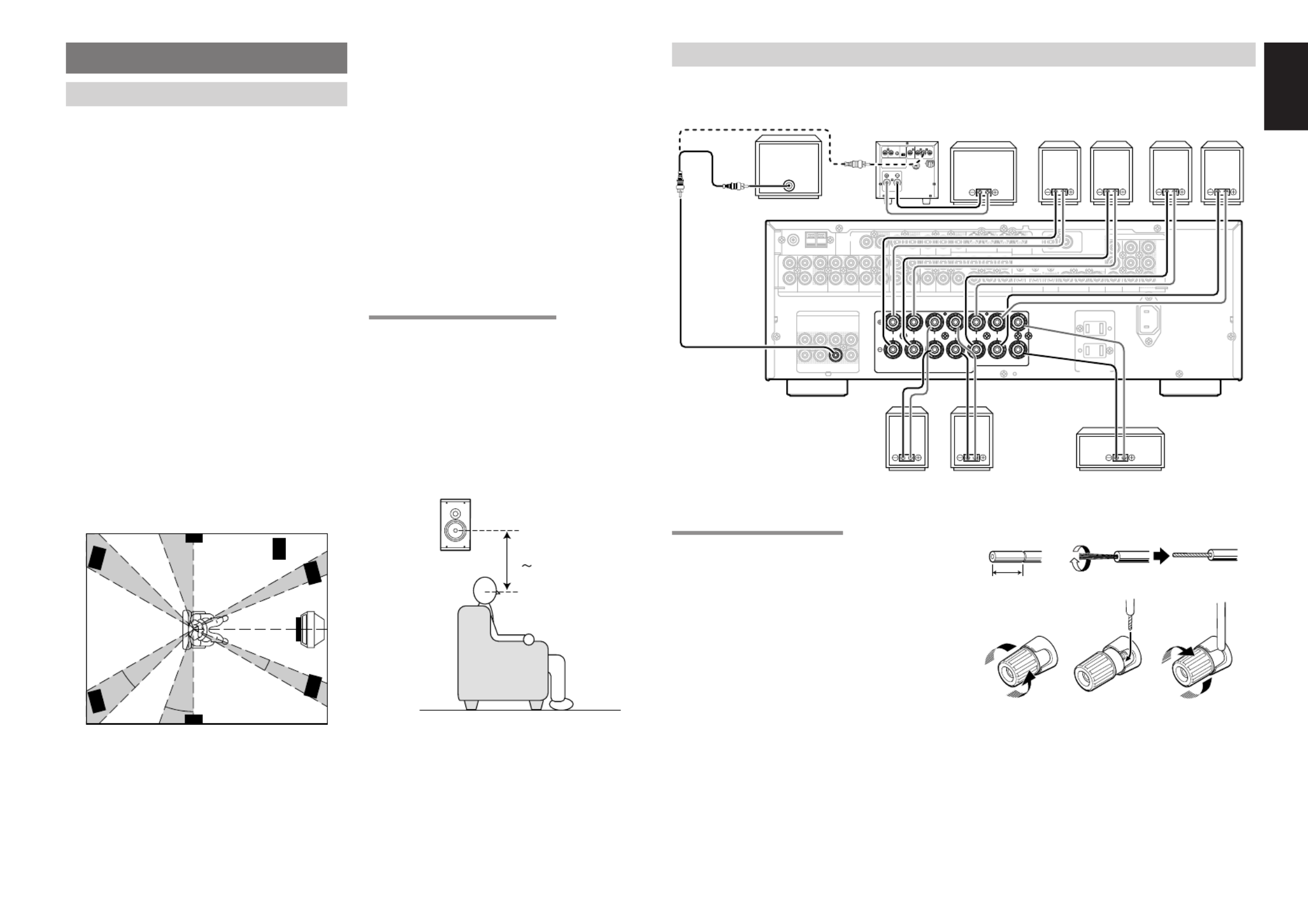
CONNECTIONS
SPEAKER PLACEMENT
The ideal surround speaker system for this unit is 7-
speaker systems, using front left and right speakers,
a center speaker, surround left and right speakers,
surround back left and right speakers, and a
subwoofer.
For best results we recommend that all front speakers
be of the same type, with identical or similar driver
units. This will deliver smooth pans across the front
sound stage as the action moves from side to side.
Your center channel speaker is very important as
over 80 % of the dialog from a typical motion picture
emanates from the center channel.
It should possess similar sonic characteristics to
the main speakers. Surround channel speakers
need not be identical to the front channel speakers,
but they should be of high quality.
The surround center speaker is useful for playback
of Dolby Digital Surround EX or DTS-ES. One of
the benefits of both Dolby Digital and DTS is that
surround channels are discrete full range, while
they were frequency limited in earlier Pro Logic“ ’
type systems.
Bass effects are an important part of home theater.
For optimal enjoyment a subwoofer should be used
as it is optimized for low frequency reproduction. If
you have full range front speakers, however, they
may be used in place of a subwoofer with proper
setting of the switches in the menu system.
Front left and right speakers
We recommend to set the front L and R speakers
with 45-60 degrees from the listening position.
Center speaker
Align the front line of the center speaker with the
front L/R speakers. Or place the center speaker a
little backward from the line.
Surround left and right speakers
When the SR4600 is used in surround operation,
the preferred location for surround speakers is on
the side walls of the room, at or slightly behind the
listening position.
The center of the speaker should face into the room.
Surround back left and right speakers
Surround back speakers are required when a full
7.1-channel system is installed.
Speakers should be placed on a rear wall, behind
the listening position.
The center of the speaker should face into the room.
Subwoofer
We recommend using a subwoofer to have maximum
bass effect. Subwoofer bears only low frequency
range so you can place it any where in the room.
HEIGHT OF THE SPEAKER UNITS
Front left and right speakers, and a center speaker
Align the tweeters and mid-range drivers on the
three front speakers at the same height, as best as
possible.
Surround left and right speakers, and surround
back speaker
Place the surround left, right and surround back
speakers higher than your ears by about 70cm 1m.–
Also place the speakers at the same height, as best
as possible.
Note:
•Use magnetically-shielded speakers for front left,
right and the center speakers when the speakers
are installed near the TV and the TV is a monitor
type.
90
°
110
°
22
°
30
°
135
°
150
°
0
°
Front Right
Front Left
Front Center
Surround Left Subwoofer
Surround
Back Left
Surround Right
Surround
Back Right
70cm
1m
CONNECTING SPEAKERS
IN OUT
MONIT OR
VCR1
MONIT OR
R SR
C
SW SBR
SL SBLL
R
SPEAKER SYSTEMS MINIMUM 6 OHMS
CENT ER
R
FRONT SU RROUND BAC K SURROUND
L LLR
DVD
OUT
IN
MONIT OR
T VDVDVCR1
OUTIN
DSS
/
VCR2
OUT
VIDEO
IN
Y
DSS
/
VCR
2
DVD
COAX.
OUT
43OPT .
OUT
21
7.1CH INPUT
L SL C SBL
SBRSWSRR
T VDVDVCR1
OUTININ OUT
DSS
/
VCR2
IN OUT
CDR/MDT APE
PRE OUT
OUTIN
CD
R
L
FM (
75
Ω
) GND A M
C
B
/
P
B
C
R
/
P
R
AUDIO
ANTENNA
RC-5
DIGIT AL
COMPONENT VIDEO
AUDIO
S-
VIDEO
AC OUTLET S
120V 60HZ
1A 120 W MAX
UNSWIT CH ED
SWIT CHED
1A 120 W MAX
AC IN
R
SPEAKER SYSTEMS MINIMUM 6 OHMS
CENT ER
R
FRONT SU RROUND BAC K
S. SPEAKER B
SURROUND
L LLR
SW
INVERT
OUTPUT
INPUT
LEVEL BTL REMOTE CONT.EXT. CONT. IN
VIDEO/
+5~13V DC SYSTEM OUT OUT
INPUT
MASTER SLAVE
MIN MAX
IN
F
U
S
E
SPEAKER SYSTEM
MINIMUM 4 O HMS
POWERED
SUBWOOFER POWER
AMPLIFIER
PASSIVE
SUBWOOFER
FRONT
RIGHT LEFT
SURROUND
SURROUND
BACK LEFT
CENTER
or RIGHT LEFT
CONNECTING SPEAKER WIRE
1.
Strip away approx. 10 mm of wire insulation.
2.
Twist the bared wire ends tight, to prevent short
circuits.
3.
Loosen the knob by turning it counterclockwise.
4.
Insert the bare part of the wire into the hole in
side of each terminal.
5.
Tighten the knob by turning it clockwise to
secure the wire.
1. 2.
3. 4. 5.
10 mm
SURROUND
BACK RIGHT


ENGLISH
12
Caution:
•
Be sure to use speakers with the specified impedance
as shown on the rear panel of this unit.
•
To prevent damage to circuitry, do not let the bare
speaker wires touch
each other and do
not let them touch
any metal part of
this unit.
•
Do not to uch the
sp eaker terminals
when the power is
on. It may cause you
to receive an electric shocks.
•Do not connect more than one speaker cable to
one speaker terminal. Doing so may damage this
unit.
Note:
•Be sure to connect the positive and negative
cables for the speaker properly. If they are miss-
connected, the signal phase will be reversed and
the signal quality will be corrupted.
CONNECTING A SUBWOOFER
Use the PRE OUT SUBWOOFER jack to connect
a powered subwoofer (power amplifier built in ).
If your subwoofer is a passive type (power amplifier
is not built in), connect a monaural power amplifier
to the PRE OUT SUBWOOFER jack and connect
the subwoofer to the amplifier.
CONNECTING AUDIO COMPONENTS
IN OUT
MONIT OR
VCR1
MONIT OR
R SR
C
SW SBR
SL SBLL
R
SPEAKER SYSTEMS MINIMUM 6 OHMS
CENT ER
R
FRONT SU RROUND BAC K SURROUND
L LLR
DVD
OUT
IN
MONIT OR
T VDVDVCR1
OUTIN
DSS
/
VCR2
OUT
VIDEO
IN
Y
DSS
/
VCR
2
DVD
COAX.
OUT
43OPT .
OUT
21
7.1CH INPUT
L SL C SBL
SBRSWSRR
T VDVDVCR1
OUTININ OUT
DSS
/
VCR2
IN OUT
CDR/MDT APE
PRE OUT
OUTIN
CD
R
L
FM (
75
Ω
) GND AM
C
B
/
P
B
C
R
/
P
R
AUDIO
ANTENNA
RC-5
DIGIT AL
COMPONENT VIDEO
AUDIO
AC IN
S-
VIDEO
S. SPEAKER B
AC OUTLET S
120V 60HZ
1A 120 W MAX
UNSWIT CH ED
SWIT CHED
1A 120 W MAX
T APE
OUTIN
CD
R
L
IN
CDR/MD
4OPT .
OUT
1
DIGIT AL
OUT
OUT IN
L
R
L
R
OUT
L
R
L R
L R L R
R L RL RL
OUT IN
L
R
L
R
DIGITAL
INPUT
DIGITAL
OUTPUT
DIGITAL
OUTPUT
R L
R L R L
RL
L R
The output audio signal from the TAPE OUT jack
and the CD-R/MD OUT jack is the same signal
which is currently selected.
Caution:
•Do not connect this unit and other components to
mains p ower until all connections between
components have been completed.
Notes:
•Inser t all p lugs and co nnecto r s secur ely.
Incomplete connections may make noise.
•Be sure to connect the left and right channels
properly.
Red connectors are for the R (right) channel, and
white connectors are for the L (left) channel.
•Be sure to connect input and output properly.
•Refer to the instructions for each component that
is connected to this unit.
•Do not bind audio/video connection cables with
power cords and speaker cables this will result in
generating a hum or other noise.
CONNECTING DIGITAL AUDIO COMPONENTS
•There are 4 digital inputs, 2 coaxial jacks and 2
optical jacks, on the rear panel. You can use
these jacks to input PCM, Dolby Digital and DTS
bitstream signals from a CD, DVD, or other
digital source components.
•
There is one digital output coaxial jack and one
optical output jack on the rear panel. These jacks
can be connected to a CD recorder-, or a MD
deck inputs, respectively.
•
Refer to the instructions for each component.
To
setup the digital audio format of DVD player, or
other digital source s connected to digital input’
jacks.
•
Use fiber optical cables (optical) for DIG-1,2 input
jacks. Use 75 ohms coaxial cables (for digital
audio or video) for DIG-3, 4 input jacks.
•
You can designate the input for each digital input/
output jacks according to your component. See
page 17.
CD RECORDER / MD DECK CD PLAYER TAPE DECK
ANALOG AUDIO
DIGITAL AUDIO
(COAXIAL)
DIGITAL AUDIO
(OPTICAL)
Notes:
•There is no Dolby Digital RF input jack. Please
use an external RF demodulator Dolby Digital
decoder when connecting the Dolby Digital RF
output jack of the video disc player to the digital
input jack.
•The digital signal jacks on this unit conform to the
EIA standard. If you use a cable that does not
conform to this standard, this unit may not
function properly.
•Each type of audio jack works independently.
Signals input through the digital and analog jacks
are output through the corresponding digital and
analog jacks, respectively.


ENGLISH
13
IN
MONITOR
VCR1
R SR
C
SW SBR
SL SBLL
R
SPEAKER SYSTEMS MINIMUM 6 OHMS
CENTER
R
FRONT SURROUND BACK SURROUND
L LLR
DVD
OUT
IN
MONITOR
TVDVDVCR1
OUTIN
DSS
/
VCR2
OUT
VIDEO
IN
OPT.
OUT
21
7.1CH INPUT
L SL C SBL
SBRSWSRR
TVDVDVCR1
OUTININ OUT
DSS
/
VCR2
IN OUT
CDR/MDTAPE
PRE OUT
OUTIN
CD
R
L
FM (
75
Ω
) GND AM
AUDIO
ANTENNA
DIGAUDIO
S-
VIDEO
S. SPEAKER B
L R
AUDIO
OUT DIGITAL
OUT
VIDEO
OUT
AUDIO
OUT
L R
VIDEO
OUT S-VIDEO
IN
VIDEO
IN
L R
L R
MONITOR
TV
MONITOR
VCR1
S-
VIDEO
TV
2
DSS
/
VCR2
IN
IN
DSS
/
VCR2
L R
L R
L R
IN OUT
MONITOR
VCR1
MONITOR
R
C
SW SBR
L SBL
R
SPEAKER SYSTEMS MINIMUM 6 OHMS
CENTER
R
FRONT SURROUND BACK SURROUND
L LLR
DVD
OUT
IN
MONITOR
TVDVDVCR1
OUTIN
DSS
/
VCR2
OUT
VIDEO
IN
Y
DSS
/
VCR
2
DVD
COAX.
OUT
43OPT .
OUT
21
7.1CH INPUT
L SL C SBL
SBRSWSRR
TVDVDVCR1
OUTININ OUT
DSS
/
VCR2
IN OUT
CDR/MD
PRE OUT
T
M
C
B
/
P
B
C
R
/
P
R
AUDIO
RC-5
DIGITAL
COMPONENT VIDEO
AUDIO
S-
VIDEO
S. SPEAKER B
AC OUTLETS
120V 60HZ
1A 120W MAX
UNSWITC HED
SWITCHED
1A 120W MAX
AC IN
VCR1
OUTIN
VCR1
OUTIN
DVD
DVD
MONITOR
VCR1
DVD
OUT
IN
S-
VIDEO
MONITOR
Y
DVD
C
B
/
P
B
C
R
/
P
R
COMPONENT VIDEO
3
DIGITAL
L R
AUDIO
OUT DIGITAL
OUT
VIDEO
OUT S-VIDEO
OUT
S-VIDEO
IN
L R
AUDIO
OUT AUDIO
IN
L R
VIDEO
OUT IN S-VIDEO
OUT IN
L R L R
Y C
B
/
P
B
C
R
/
P
R
COMPONENT
VIDEO OUT
Y C
B
/
P
B
C
R
/
P
R
COMPONENT
VIDEO IN
L R L R
L R
L R
CONNECTING VIDEO COMPONENTS
ANALOG AUDIO
VIDEO
S-VIDEO
DVD PLAYER VIDEO PROJECTOR SATELLITE TUNER
DIGITAL AUDIO
(COAXIAL)
VCR
TV
VIDEO, S-VIDEO , COMPONENT JACKS
There are 3 types of video jacks on the rear panel.
VIDEO jack
The video signal for the VIDEO jacks is the
conventional composite video signal.
S-VIDEO jack
The video signal is separated into luminance (Y) and
color (C) signals for the S-VIDEO jack. The S-VIDEO
signals enables high-quality color reproduction. If
your video component has an S-VIDEO output, we
recommend to use it. Connect the S-VIDEO output
jack on your video component to the S-VIDEO input
jack on this unit.
Component jack
Make component video connections to a TV or
monitor with component inputs to produce higher
quality video images. Use a component video cable
or 3 video cords to connect the component video
out jacks on the SR4600 to the monitor.
Video convert
The input signals of video and S-video are converted
each other, and each of the converted video signals
can be output.
For example, the video input signal from the VIDEO
jack can be output to the monitor jack of S-VIDEO.
Moreover, the contrary is also possible. Priority is
given to S-VIDEO jack when having input by VIDEO
and S-VIDEO jack from the same source.
Notes:
•
Be sure to connect the left and right audio channels
properly.
Red connectors are for the R (right) channel, and
white connectors are the for L (left) channel.
•Be sure to connect the inputs and outputs of the
video signals properly.
•If you connect the S-VIDEO or component signal
to the S-VIDEO or component jack on this unit, it
is not necessary to connect the conventional video
signal to the VIDEO (composite) jack. If you use
both video inputs, this unit gives priority to the S-
VIDEO signal.
•Each type of video jack works independently.
Signals input to the VIDEO (composite) and S-
VIDEO jacks or component are output to the
corresponding VIDEO (composite) and S-VIDEO
or component jacks, respectively.
•You may need to setup the digital audio output
format of your DVD player, or other digital source
components. Refer to the instructions of the each
component connected to the digital input jacks.
•There is no Dolby Digital RF input jack. Please
use an external RF demodulator with a Dolby
Digital decoder to connect a video disc player
which has a Dolby Digital RF output jack to the
digital input jack on this unit.
DIGITAL AUDIO
(OPTICAL)


ENGLISH
14
MONIT OR
VCR1
R SR
C
SW SBR
SL SBLL
R
SPEAKER SYSTEMS MINIMUM 6 OHMS
CENT ER
R
FRONT SU RROUND BAC K SURROUND
L LLR
DVD
OUT
IN
MONIT OR
T VDVDVCR1
OUTIN
DSS
/
VCR2
OUT
VIDEO
IN
1
7.1CH INPUT
L SL C SBL
SBRSWSRR
T VDVDVCR1
OUTININ OUT
DSS
/
VCR2
IN OUT
CDR/MDT APE
PRE OUT
OUTIN
CD
R
L
FM (
75
Ω
) G ND AM
AUDIO
ANTENNA
AUDIO
S
V
S. SPEAKER B
R SR
C
SW SBR
SL SBLL
PRE OUT
AUDIO
7.1CH INPUT
L SL C SBL
SBRSWSRR
L
R
FRONT SURR.
SURR.
BACK
SUB
WOOFER
CENTER
L
R
FRONT SURR.
SURR.
BACK
SUB
WOOFER
CENTER
R L
L R
R L
RL R L
LR
L R L R
L RLR
L R
R L
. SPEAKER B
IN OUT
MONIT OR
VCR1
MONIT OR
R
N
IMUM 6 OHMS
CENT ER
R
ROU ND BACK SU RROUND
LL
R
DVD
OUT
IN
MONIT OR
T V
Y
DSS
/
VCR
2
DVD
COAX.
OUT
43OPT .
OUT
21
7.1CH INPUT
L SL C SBL
SBRSWSRR
T V
C
B
/
P
B
C
R
/
P
R
RC-5
DIGIT AL
COMPONENT VIDEO
S-
VIDEO
AC OUTLET S
120V 60HZ
1A 120 W MAX
UNSWIT CH ED
SWIT CHED
1A 120 W MAX
AC IN
IN OUT
RC-5
REMOTE
CONTROL REMOTE
CONTROL REMOTE
CONTROL
IN
OUT
IN
OUT
IN
OUT
EXTERNAL INTERNAL EXTERNAL INTERNAL EXTERNAL INTERNAL
1
RC OUT
2
ADVANCED CONNECTING
CONNECTING MULTI CHANNEL AUDIO SOURCE
The 7.1CH INPUT jacks are for multichannel audio
source such as a SACD multichannel player, DVD
audio player or external decoder.
If you use these jacks, switch on the 7.1CH INPUT
and set the 7.1CH INPUT level by using the 7.1
channel input level menu. See page 29.
CONNECTING AN EXTERNAL POWER AMPLIFIER
The PREOUT jacks are for connecting external
power amplifiers.
Be sure to connect each speaker to the corresponding
external power amplifier.
POWER
AMPLIFER
DVD AUDIO PLAYER
or
SACD MULTI CHANNEL PLAYER
Center
Front
Left
Front
Right
Surround
Left
Surround
Right
Subwoofer
CONNECTING THE REMOTE CONTROL JACKS
MD DECK
CD RECORDER
q
You can control other Marantz products through
this unit with the remote control by connecting the
REMOTE CONTROL terminals on each unit.
The signal transmitted from the remote control is
received by the remote sensor on this unit. Then the
signal is sent to the connected device through this
terminal. Therefore you only need to aim the remote
at one unit. Also, if a Marantz power amplifier (some
models excluded) is connected to one of these
terminals, the power amplifier s, power switch is’
synchronized with this unit s power switch.’
Set the REMOTE CONTROL SWITCH on the units,
other than the main unit to EXT.(EXTERNAL) for
this feature.
CD PLAYER
OPTION
w
Whenever external infrared sensors or similar
devices are connected to RC-5 IN of the SR4600,
be sure to always disable operation of the infrared
sensor on the main unit by using the following
procedure.
1.
Hold down the button and7.1CH INPUT
MENU button on the front panel at the same
time for five seconds.
2.
The setting is shown on the FL“IR=ENABLE”
DISPLAY.
3.
Press the or cursor button to change this
to IR=DISABLE .“ ”
4.
Press the button. Once this setting isENTER
made, the infrared sensor on the main unit is
disabled.
Note:
Be sure to set to when external“IR=ENABLE”
infrared sensor s or similar devices are not
connected. Otherwise, the main unit will be
unable to receive remote control commands.
5.
To restore the original setting, perform steps 1
to 4 to set to “IR=ENABLE”.
Surround
Back Left
Surround
Back Right


ENGLISH
15
CONNECTING THE ANTENNA TERMINALS
IN OUT
MONIT OR
VCR1
MONIT OR
R SR
C
SW SBR
SL SBLL
R
SPEAKER SYSTEMS MINIMUM 6 OHMS
CENT ER
R
FRONT SU RROUND BAC K SURROUND
L LLR
DVD
OUT
IN
MONIT OR
T VDVDVCR1
OUTIN
DSS
/
VCR2
OUT
VIDEO
IN
Y
DSS
/
VCR
2
DVD
COAX.
OUT
43OPT .
OUT
21
7.1CH INPUT
L SL C SBL
SBRSWSRR
T VDVDVCR1
OUTININ OUT
DSS
/
VCR2
IN OUT
CDR/MDT APE
PRE OUT
OUTIN
CD
R
L
FM (75
Ω
) G ND AM
C
B
/
P
B
C
R
/
P
R
AUDIO
ANTENNA
RC-5
DIGIT AL
COMPONENT VIDEO
AUDIO
S-
VIDEO
S. SPEAKER B
AC OUTLET S
120V 60HZ
1A 120 W MAX
UNSWIT CH ED
SWIT CHED
1A 120 W MAX
AC IN
FM (75
Ω
) G ND AM
ANTENNA
FM
ANTENNA
FM EXTERNAL
ANTENNA
AM LOOP
ANTENNA AM EXTERNAL
ANTENNA
ASSEMBLING THE AM LOOP ANTENNA
1.
Release the vinyl tie and take out the connection
line.
2.
Bend the base part in the reverse direction.
3.
Insert the hook at the bottom of the loop part
into the slot at the base part.
CONNECTING THE SUPPLIED ANTENNAS
Connecting the supplied FM antenna
The supplied FM antenna is for indoor use only.
During use, extend the antenna and move it in
various directions until the clearest signal is received.
Fix it with push pins or similar implements in the
position that will cause the least amount of distortion.
If you experience poor reception quality, an outdoor
antenna may improve the quality.
Connecting the supplied AM loop antenna
The supplied AM loop antenna is for indoor use only.
Set it in the direction and position it to where you
receive the clearest sound. Put it as far away as
possible from the unit, televisions, speaker cables,
and power cords.
If you experience poor reception quality, an outdoor
antenna may improve the quality.
1.
Press and hold down the lever of the AM antenna
terminal.
2.
Insert the bare wire into the antenna terminal.
3.
Release the lever.
CONNECTING AN FM OUTDOOR ANTENNA
Notes:
• Keep the antenna away from noise sources (neon
signs, busy roads, etc.).
• Do not put the antenna close to power lines. Keep
it well away from power lines, transformers, etc.
• To avoid the risk of lightning and electrical shock,
grounding is necessary.
CONNECTING AN AM OUTDOOR ANTENNA
An outdoor antenna will be more effective if it is
stretched horizontally above a window or outside.
Notes:
•Do not remove the AM loop antenna.
•To avoid the risk of lightning and electrical shock,
grounding is necessary.
4.
Place the antenna on stable surface.


ENGLISH
16
1. INPUT
SIMPLE SETUP
2. SPEAKER
3. PREFERENCE
5. DOLBY PLII
6. CSII
4. SURROUND
CD
TAPE
CD-R
TV
DVD
VCR1
DSS
SUBW
L&R
CENT
SL&SR
SB
SB SIZE
LPF/HPF
BASS
(Subwoofer)
(Front Left & Right)
(Center)
(Surround Left & Right)
(Surround Back)
(Surround Back Size)
(Low/High Pass Filter)
(Bass Mix)
→ → →SMALL LARGE
→ → → →80 100 120
→ → →BOTH MIX
SMALL
100Hz
BOTH
→ → →YES NONE YES
2CH
→ → →LARGE SMALL LARGE
→ → → →SMALL LARGE NONE SMALL
SMALL→ → → →SMALL LARGE NONE
→LARGE MEDIUM SMALL→ → →
→ → → →1CH 2CH NONE
→ → →MANUAL AUTO MANUAL
→ → →NOMAL ECONOMY
ECONOMY
→…→ →…→ →…AUTO STEREO
AUTO
L
R
(Front L)
(Front R)
(Center)
(Surround L)
(Surround R)
(Subwoofer)
(Surround back L)
(Surround back R)
C
SL
SR
T-MODE
L
CENT
R
SR
SBR
SBL
SL
SUBW
(Test Tone)
(Front L-ch Level)
(Center-ch Level)
(Front R-ch Level)
(Surround R-ch
Level
)
(Surround Back R-ch Level)
(Surround Back L-ch Level)
(Surround L-ch Level)
(Subwoofer Level)
STBY
(Standby Mode)
PARAM
PANORAMA
SR
HT-EQ
LFE
(
Surround
Mode)
(LFE Level)
TRUBASS
SRS DIALOG
7.1-V
(7.1ch Video Input)
D1 AUTO / D2 AUTO /D3 AUTO / D4 AUTO
(Digital AUTO mode)
DIG.1 / DIG.2 / DIG.3 / DIG.4 (Digital Fixed mode)
ANALOG
SPEAKERS
ROOM
2-1. SPEAKERS SIZE setup
2-2. SPEAKERS DISTANCE setup
2-3. SPEAKERS LEVEL setup
3.0m(10ft)
3.0m(10ft)
3.0m(10ft)
3.0m(10ft)
3.0m(10ft)
OFF
0dB
→
2.0(2ch)
→
2.1(2.1ch)
→ … →
7.0(7ch)
→
7.1(7.1ch)
→
→ →…→0.3m(1ft) 9.0m(30ft)
→ →…→0.3m(1ft) 9.0m(30ft)
→ →…→0.3m(1ft) 9.0m(30ft)
→ →…→0.3m(1ft) 9.0m(30ft)
SW
SBL
SBR
3.0m(10ft)
3.0m(10ft)
3.0m(10ft)
→ →…→0.3m(1ft) 9.0m(30ft)
→ →…→0.3m(1ft) 9.0m(30ft)
→ →…→0.3m(1ft) 9.0m(30ft)
→ →…→ →…→-10 0 +10 0dB
0dB
0dB
0dB
0dB
0dB
0dB
0
0
LAST
→ →…→ →…→-10 0 +10
→ →…→ →…→-10 0 +10
→ →…→ →…→-10 0 +10
→ →…→ →…→-10 0 +10
→ →…→ →…→-10 0 +10
→ →…→ →…→-10 0 +10
0dB→ →…→ →…→-15 0 +10
→→→→→→→→0123456
→ → → →…→ →LAST TV DVD V—OFF
→ → →OFF ON (
∗
)
→ → → →0 -10 OFF (
∗
)
→ → →DEFAULT CUSTOM DEFAULT
OFF
→ → →OFF ON
DIMENSION
3
→→→→→→→→0123456
C-WIDTH
(Parameter)
(Center Width) 3
→→→→→→→→→01234567
D4-AUTO
D1-AUTO
D3-AUTO
ANALOG
ANALOG
ANALOG
D2-AUTO
SETUP MENU
→ →…→0.3m(1ft) 9.0m(30ft)
→→→→→→→→0123456
SETUP
After all components are connected, initial setup
must be performed.
SETUP MENU SYSTEM
The SR4600 incorporates an menu on the front
display, which makes various operations possible by
using the ) and cursor ( , , , ENTER buttons.
ENTER THE DESIRED MENU ITEM
OF THE SETUP MENU
1.
Turn on the unit.
2.
Press the button of the remote control.AMP
3.
Press the button or the button ofMENU ENTER
the remote control to enter the SETUP MENU.
4.
Press the or button to select the cursor
SETUP MENU item.
5.
Press the button or the ENTER MENU button
to enter the desired menu item.
After finishing all setup, press the buttonMENU OFF
to exit the SETUP MENU.
MENU STRUCTURE
Initial state
EXIT
DT S
PURE DIRECT
AUT O
321
T .T ONE
MENU OFF
SET UP/
MENU
OSD
VOL.
T V
VOL.
MAIN
SLEEP
MUT E
AMP
ENTER
AUX1
MAIN
4.
2.
3. 5.
3. 5.
SURROUN D
AV SUR ROUND RECEIVER SR4600
IN PUT SELEC TOR
PHON ES
ST AN DBY
7.1CH IN PUT
PURE
SET UP
DIRECT
SIMP LE
AUT O
HT - E Q
MEN U
EN T E R
DISPLA Y
MEMORY
EXIT
BAN D
MODE
DISP MULTI TUN ED ST V AUTO
–
OFF N I GH T P EAK AN ALOG
DIG ITAL
ATT
SLEEP SURRAUTO DI RECT EQD ISC 6.1 M T X 6.1
DIGI T AL
SURROUND
AAC
PC M
L
C
R
SL S SR
LFE
POWE R ON/ST ANDB Y
S. SPEAK ER B
3. 5. 4. 5.


17
ENGLISH
1. INPUT SETUP
(ASSIGNABLE DIGITAL INPUT)
Four digital inputs can be assigned as the desired
source.
Use this menu to select the digital input jack to be
assigned to the input source.
The Input Setup consists of 6 items, which are as
below.
• D1AUTO to D4AUTO : Digital AUTO mode
If the input signal from the selected source is digital
signal, this unit chooses a digital input automatically.
• DIG.1 to DIG.4 : Digital FIXED mode
The SR4600 chooses a digital input regardless of
a input signal from the selected source.
• ANA : Analog mode
Use this menu to select the digital input jack to be
assigned to the input source.
1.
Select 1.INPUT“ ” in SETUP MENU with the
or cursor button.
2.
Press the button to enter the menu.ENTER
3.
Press the or cursor button to select the input
source.
4.
Press or cursor button to select the input
function.
Select DxAUTO DIG.x ANA“ ”, “ ” or “ ” for input
sources.
The relation of the speakers number and
conectted speaker
The relation of the room size and floor space
The relation of the room size and floor space is a
roughly standard.
Front Front Surround Surround Sub
CHANNEL L/R Center L/R Back L/R woofer
(F) (C) (S) (SB) (SW)
7.1 ch LARGE SMALL SMALL 2ch YES
7.0 ch LARGE SMALL SMALL 2ch NONE
6.1 ch LARGE SMALL SMALL 1ch YES
6.0 ch LARGE SMALL SMALL 1ch NONE
5.1 ch LARGE SMALL SMALL NONE YES
5.0 ch LARGE SMALL SMALL NONE NONE
4.1 ch LARGE NONE SMALL NONE YES
4.0 ch LARGE NONE SMALL NONE NONE
3.1 ch LARGE SMALL NONE NONE YES
3.0 ch LARGE SMALL NONE NONE NONE
2.1 ch LARGE NONE NONE NONE YES
2.0 ch LARGE NONE NONE NONE NONE
SIMPLE SETUP
You can setup the speaker conditions quickly with
SIMPLE SETUP menu. In this menu, the number
of speakers and speaker delay time can be set.
These settings can be changed more detail in “2.
SPEAKER” setup menu.
Press the button on the unit toSIMPLE SETUP
enter this menu.
1.
Press the button on the unitSIMPLE SETUP
to enter the menu.“SPEAKERS”
2.
Press or cursor button to select the speaker
number.
3.
Press the cursor button to enter the “ ”ROOM
menu.
4.
Press or cursor button to select the room
size.
5.
After finishing all setup,
press the
cursor
button
to exit the SIMPLE SETUP menu.
Note
• All Simple Setup menu is reset when the speaker
setting is changed with Speaker Setup menu.
SIZE Floor Width Depth Imaging Distance
space (W) (D)
Front (F) 6 ft. (1.8 m)
Center (C) 5 ft. (1.5 m)
SMALL 10 m
2
2.7 m 3.6 m Surround (S) 4 ft. (1.2 m)
Surr. Back (SB) 5 ft. (1.5 m)
Sub Woofer (SW) 5 ft. (1.5 m)
Front (F) 7 ft. (2.1 m)
Center (C) 6 ft. (1.8 m)
MEDIUM 16 m
2
3.6 m 4.5 m Surround (S) 5 ft. (1.5 m)
Surr. Back (SB) 7 ft. (2.1 m)
Sub Woofer (SW) 6 ft. (1.8 m)
Front (F) 9 ft. (2.7 m)
Center (C) 8 ft. (2.4 m)
LARGE 24 m
2
4.5 m 5.4 m Surround (S) 7 ft. (2.1 m)
Surr. Back (SB) 8 ft. (2.4 m)
Sub Woofer (SW) 8 ft. (2.4 m)
MENU STRUCTURE of Simple Setup
3.0 (ch)
3.1 (ch)
2.0 (ch)
2.1 (ch)
4.0 (ch)
4.1 (ch)
5.0 (ch)
5.1 (ch)
6.0 (ch)
6.1 (ch)
7.0 (ch)
7.1 (ch)
LARGEROOM
MEDIUM
SMALL
SPEAKERSSIMPLE SETUP
SL
SR
C W
D
TV
SW
FR
FL
SBL
SBR
(F)
(F)
(S)
(S)
(C)
(SW)
(SB)
(SB)
DT S
PURE DIRECT
AUT O
T .T ONE
MENU OFF
SET UP/
MENU
OSD
VOL.
T V
VOL.
MAIN
SLEEP
MUT E
ENTER
4. 5.
2. 5.
1. 3. 5.
SURROUN D
SUR ROUND RECEIVER SR460 0
DOWN
PHON ES
MUT E
PURE
SET UP
DIRECT
SIMP LE
AUT O
HT - E Q
MEN U
EN T E R
DISPLA Y
MEMORY
CLEAR
T - MODE
EXIT
BAN D
MODE
DISP MULTI TUN ED ST V AUTO
–
OFF N I GH T P EAK AN ALOG
DIG ITA L
ATT
SLEEP SURRAUTO DI RECT EQDISC 6.1 M TX 6. 1
DIGI T AL
SURROUND
AAC
PC M
L
C
R
SL S SR
LFE
S. SPEAK ER B
2. 4. 3. 5.
1.
SURROUN D
ND RECEIVER S R4600
D
NE S
EAKE R
PURE
SET UP
DIRECT
SIMP LE
AUT O
HT - E Q
MEN U
EN T E R
DISPLA Y
MEMORY
CLEAR
T - MODE
EXIT
BAN D
MODE
DISP V MULTI TUN ED STAUTO
–
OFF N I GH T P EAK AN ALOG
DIG ITAL
ATT
SLEEP SURRAUTO DIRECT DISC 6.1 MTX 6.1 EQ
DIGI T AL
SURROUND
AAC
PC M
L
C
R
SL S SR
LFE
4. 5. 2. 5.
1. 3. 5.


ENGLISH
18
5.
If you finish these setup, press the or
cursor button to select TO MAIN MENU then“ ”
press the button to return the SETUPENTER
MENU.
Or press the or cursor button to select
“ ”EXIT then press the button to exitENTER
the SETUP MENU.
Notes:
•When a DTS-LD or DTS-CD is playing, this setup
is not available. This is to avoid noise being
generated from the analog input.
• “ ” If Dx-AUTO is selected and a DVD, compact
disc or LD is fast forwarded during playback,
decoded signals may produce a skipping sound. In
such cases, change the setting to DIGITAL.
•
Same digital input function cannot be set. In this
case, the previous setting is set to ANALOG. Same
digital input number cannot be set in Digital AUTO
mode and Digital Fixed mode. For example,
D1AUTO and DIG.1 are not set at same time.
• The TUNER is fixed to the analog input, and can
not be selected for any digital input.
2. SPEAKER SETUP
After you have installed the SR4600, connected all
the components, and determined the speaker layout,
it is now time to perform the settings in the Speaker
Setup menu for the optimum sound acoustics for
your environment and speaker layout.
Before you perform the following settings, it is
important that you first determine the following
characteristics:
2-1. SPEAKERS SIZE
When setting the speaker size in the SPEAKER
SIZE sub-menu, use the guidelines given below.
Large:
The complete frequency range for the channel
you are setting will be output from the speaker.
Small:
Frequencies of the channel you are setting
lower than approx. 100Hz will be output from the
subwoofer.
If the Subwoofer is set to and the front“ ”NONE
speakers are set to then the sound may“ ”Large,
be output from both the left and right speakers.
MENU STRUCTURE of Speakers Size setup
Speakers Size
Select when a subwoofer is connected.
Select if the front speakers are large sized.
Select if the center speaker is small sized.
Select when a subwoofer is not connected.
Select if the front speakers are small sized.
Select if the center speaker is large sized.
Select if no center speaker is connected.
Select if no surround left and right speakers are connected.
Select if the surround left and right speakers are large sized.
Select if the surround left and right speakers are small sized.
YES
NONE
LARGE
SMALL
SMALL
L & R
CENTER
LARGE
NONE
SMALL
LARGE
NONE
SL & SR
Select if no surround back speaker is connected
Select if the surround back left and right speakers are connected
Select if the surround back speaker is connected
2CH
NONE
SB
Select if the surround back speaker(s) is large sized
This menu (SB SIZE) will not be displayed, if SB is set "NONE".
Select if the surround back speaker(s) is small sized
SMALL
LARGE
***
SB SIZE
Select this when the bass speaker is about 8cm(3 3/16inches)
Select this when the bass speaker is about 10cm(3 15/16inches)
Select this when the bass speaker is about 12cm(4 3/4inches)
80
100
120
LPF/HPF
SUBW
2-1. SPEAKERS SIZE
setup
1CH
MAIN MENU
exit SETUP
MENU
Speakers Distance
setup
TO MAIN
MENU
EXITNEXT
In this case, the audio signal is emitted form
the Surround back L output terminal.
1.
Select 2.SPEAKER“ ” in SETUP MENU with
or cursor button,
2.
Press the button to enter the menu.ENTER
The first sub-menu item is 2-1.Speakers Size“ ”
setup.
3.
Press or cursor button to select the each
speaker.
4.
Press or cursor button to select the setting
of size to each speaker.
5.
If you finish these setup, press the or
cursor button to select “NEXT”.
6.
Press the button to enter the next ENTER “2-
2. Speakers Distance” setup.
Or press the or cursor button to select
“ ”EXIT then press the button to exitENTER
the SETUP MENU.
Or press the or cursor button to select “TO
MAIN MENU then press the ” ENTER button to
return the SETUP MENU.
DT S
PURE DIRECT
AUT O
T .T ONE
MENU OFF
SET UP/
MENU
OSD
VOL.
T V
VOL.
MAIN
SLEEP
MUT E
ENTER
4. 5.
2. 5.
1. 3. 5.
MENU STRUCTURE of Speakers Size setup
SURROUN D
ND RECEIVER S R4600
D
NE S
EAKE R
PURE
SET UP
DIRECT
SIMP LE
AUT O
HT - E Q
MEN U
EN T E R
DISPLA Y
MEMORY
CLEAR
T - MODE
EXIT
BAN D
MODE
DISP M ULTI TUN ED STAUTO V
–
OFF N IG HT P EAK ANALOG
DIG ITAL
ATT
SLEEP SURRAUTO DIRECT DISC 6.1 M TX 6.1 E Q
DIGI T AL
SURROUND
AAC
PC M
L
C
R
SL S SR
LFE
4. 5. 2. 5.
1. 3. 5.


19
ENGLISH
2-2. SPEAKERS DISTANCE
Use this parameter to specify the distance of each
speaker’s position from the listening position. The
delay time is automatically calculated according to
these distances.
Begin by determining the ideal or most commonly
used seating position in the room.
This is important for the timing of the acoustics to
create the proper sound space that the SR4600
and today’s sound systems are able to produce.
Note that the speakers that you selected “ ”None
for in the Speaker Config sub-menu will not appear
here.
1.
Enter to the 2-2. Speakers Distance from the“ ”
previous “2-1. Speakers Size”.
2.
Press or cursor button to select the each
speaker.
3.
Press or cursor button to set the distance
from your listening position for each speaker.
4.
After finishing the Speaker Distance setup,
press the or cursor button to select “ ”.NEXT
5.
Press the button to enter the nextENTER
“ ”Speaker Level setup.
Or press the or cursor button to select
“ ”EXIT then press the button to exitENTER
the SETUP MENU.
Or press the or cursor button to select “TO
MAIN MENU then press the ” ENTER button to
return the SETUP MENU.
Or press the or cursor button to select
“ ”RETURN then press the button toENTER
return the previous 2-2. Speakers Distance“ ”
setup.
L&R :
Set the distance from the front left and right
speakers to your normal listening position
between 1 and 30 feet in 1.0 foot interval (0.3 to
9 meters in 0.3-meter intervals).
C :
Set the distance from the center speaker to your
normal listening position between 1 and 30 feet
in 1.0 foot interval
(0.3 to 9 meters in 0.3-meter intervals).
SL&SR:
Set the distance from the surround left and right
speaker to your normal listening position
between 1 and 30 feet in 1.0 foot interval (0.3 to
9 meters in 0.3-meter intervals).
MENU STRUCTURE of Speakers Distance setup
button
button
30 ft (9.0m)
29 ft (8.7m)
L&R
C
SL&SR
SW
SB
2 ft (0.6m)
EXIT
Minimum
Maximum
1 ft interval (1 ft = 0.3 m)
RETURNTO MAIN MENU
1 ft (0.3m)
NEXT
Distance
Speakers
Size setup
MAIN
MENU
exit SETUP
MENU
Speakers
Level setup
Speakers
Speakers
Distance setup
Speakers
Size setup
DT S
PURE DIRECT
AUT O
T .T ONE
MENU OFF
SET UP/
MENU
OSD
VOL.
T V
VOL.
MAIN
SLEEP
MUT E
ENTER
4. 5.
2. 5.
1. 3. 5.
MENU STRUCTURE of Speakers Distance setup
SW :
Set the distance from the subwoofer to your
normal listening position between 1 and 30 feet
in 1.0-foot intervals (0.3 to 9 meters in 0.3-meter
intervals).
SB:
Set the distance from a surround back speaker
to your normal listening position between 1 and
30 feet in 1.0-foot intervals (0.3 to 9 meters in
0.3-meter intervals).
Note:
• “ ” “ ”Speakers that you selected No or None for in
the Speaker Size menu will not appear.
SURROUN D
ND RECEIVER S R4600
D
NE S
EAKE R
PURE
SET UP
DIRECT
SIMP LE
AUT O
HT - E Q
MEN U
EN T E R
DISPLA Y
MEMORY
CLEAR
T - MODE
EXIT
BAN D
MODE
DISP TUN ED V MULTI AUTO ST
–
OFF N IG HT P EAK AN ALOG
DIG ITAL
ATT
SLEEP SURRAUTO DI RECT DI SC 6. 1 MTX 6.1 E Q
DIGI T AL
SURROUND
AAC
PC M
L
C
R
SL S SR
LFE
4. 5. 2. 5.
1. 3. 5.


ENGLISH
20
1.
When you select in T-MODE menu“ ”MANUAL
by pressing the or button, this unit will emit
a pink noise from the front left speaker. At this
time, adjust the desired level of the master
volume. Remember the level of this noise and
then press the button. This unit will emit the
pink noise from the center speaker.
2.
Using the and cursor buttons, adjust the
volume level of the noise from the center
speaker so that it is the same level as the front
left speaker (Note that this can be adjusted to
any level between 10 and +10 dB in 1dB–
intervals).
3.
Press the cursor button again. This unit will
now emit the pink noise from the front right
speaker.
4.
Repeat steps 2 and 3 above for the front right
and other speakers until all speakers are
adjusted to the same volume level.
5.
Press the button, you can stop theENTER
test tone mode.
Or press the or cursor
button to select “ ”EXIT
then press the
ENTER
button to exit the SETUP MENU.
Or press the or button to select
“ ”RETURN then press the button toENTER
return the previous “2-2.
Speakers Distance
”
setup.
Notes:
• “ ”Speakers that you selected None for in the
Speaker Size Setup menu will not appear.
•The setup level for each channel is memorized for
reproduction in all surround mode by this method
exclude CS mode, Multi channel stereo mode and
7.1 ch input mode.
•To adjust the speaker levels for 7.1-channel input
sources, you will need to use the 7.1CH Level
Input setup menu.
2-3. SPEAKERS LEVEL SETTING WITH TEST TONE
Here you will set the volume for each speaker so
that they are all heard by the listener at the same
level. Moreover, if the button is pressed,T.TONE
unit can enter into this menu directly.
Note:
•The speaker level settings are not available in 7.1
Channel Input mode, CS mode and Multi Channel
Stereo mode.
T(TEST) MODE :
Selects “ MANUAL” or “AUTO” for generating
mode of test tone or cursor button.
If you select by pressing the button, the“ ”AUTO
test tone will be cycled through in a circular pattern
which is L (Left) C (Center) R (Right) → → → SR
(Surround Right) SBR (Surround Back →Right) →
SBL (Surround Back SL (Surround Left) Left) → →
SW (Subwoofer) .. increments of 2 seconds→ L →
for each channel.
Using the and cursor buttons, adjust the
volume level of the noise from the speaker so that
it is the same level for all speaker.
Press the button, you can stop the testENTER
tone mode. Or press the or cursor button to
select EXIT“ ” then press the button to exitENTER
the SETUP MENU.
Or press the or cursor button to select
“ ”RETURN then press the ENTER button to return
the previous 2-2. Speakers Distance“ ” setup.
If you select , adjust the output level of“ ”MANUAL
each speaker as follow.
2-4. SPEAKERS LEVEL SETTING WITHOUT TEST TONE
Channel level (speaker level) can be adjusted
without using test tone.
Note:
•Four channel level settings can be memorized for
reproduction: the 7.1 ch input mode, CS mode,
Multi channel stereo mode, and all other surround
modes, respectively.
1.
Set the surround mode or 7.1 ch input mode
which you want to adjust the channel level.
2.
Press the button on the remote.CH.SEL
3.
Select the desired channel (speaker) with the
or cursor buttons.
4.
Adjust the level with the or cursor buttons.
5.
After completing the setup, press the CH.SEL
button again.
MENU STRUCTURE of Speakers Level setup
MANU AUTO
SW
L C
SBR
R
SL SR
EXITRETURNTO MAIN MENU
SBL
Speaker
(Auto)
Speakers
Distance setup
MAIN
MENU
exit SETUP
MENU
Test Tone mode
Speakers
Level setup
Speakers
Distance
setup
Direct select
by remote
control
Listening
Positiom
1. 5.
5.
2. 5.
1. 3. 5.
NIGHT
CSII EX/ES VIRT U AL
DT S
PURE DIRECT
AUT O
321
654
T .T ONE
MENU OFF
SET UP/
MENU
OSD
VOL.
T V
VOL.
MAIN
SLEEP
MUT E
AMP
ENTER
AUX1
MAIN
MENU STRUCTURE of Speaker Level setup
+10dB
+9dB
-9dB
Minimum
Maximum
1 dB interval
Reference
1 dB interval
-10dB
(SW -15 dB)
button
button
0dB
SURROUN D
AV SUR ROUND RECEIVER SR4600
IN PUT SELEC TOR
PHON ES
ST AN DBY
7.1CH IN PUT
PURE
SET UP
DIRECT
SIMP LE
AUT O
HT - E Q
MEN U
EN T E R
DISPLA Y
MEMORY
CLEAR
T - MODE
EXIT
BAN D
MODE
DISP V MULTI TUN ED STAUTO
–
OFF N IG HT AN AL OGPEAK
DIG ITAL
ATT
SLEEP SURRAUTO DIRECT EQDI SC 6.1 M TX 6.1
DIGI T AL
SURROUND
AAC
PC M
L
C
R
SL S SR
LFE
POWE R ON /STA NDBY
S. SPEAK ER B
1. 5. 5.
1. 2. 5.
1. 3. 5.


21
ENGLISH
HT-EQ :
Select to active the HT-EQ with the or cursor
buttons.
The tonal balance of a film soundtrack will be
excessively bright and harsh when played back
over audio equipment in the home. This is
because film soundtracks were designed to be
played back in large movie theater environments.
Activating the HT-EQ feature when watching a
film made for movie theaters corrects this and
restores the correct tonal balance.
The HT-EQ feature is available except in the
following modes.
• 7.1 CH INPUT
• PURE-DIRECT
• When VIRTUAL is set for the surround mode
LFE LEVEL :
Select the output level of the LFE signal included
in the Dolby Digital signal or the DTS signal.
Select 0 dB, -10 dB or OFF with the or cursor
buttons.
When you select TO MAIN MENU by pressing“ ”
the or button, you can return the SETUP MAIN
MENU by pressing the ENTER button.
4. SURROUND
This sub menu is to adjust channel levels for each
surround setting groups. There are three surround
setting groups shown below. Therefore if settings
for a surround mode are changed, settings for all
other surround modes in the same group are also
changed.
Surround setting group
1 : AUTO, DOLBY, DTS, EX/ES, VIRTUAL,
STEREO
2 : Multi-ch stereo
3 : CS II
1.
Select “4. SURROUND” in SETUP MENU
with
or
cursor button.
2.
Press the ENTER button.
3.
To select a desired item, press or cursor
button.
4.
Using the or cursor button to select the mode
or adjust the volume level of each speaker.
5.
When you select TO MAIN MENU by pressing“ ”
the or button, you can return the SETUP
MENU by pressing the ENTER button.
Or press the or cursor button to select
“ ”EXIT then press the button to exitENTER
the SETUP MENU.
SR(SURR-MODE) :
Select the desired surround mode with or
cursor button.
• If one of the following modes is selected, all other
modes are also set to the same. AUTO, DOLBY,
DTS, EX/ES, VIRTUAL, STEREO.
5.
When you select TO MAIN MENU by pressing“ ”
the or button, you can return the SETUP
MENU by pressing the ENTER button.
Or press the or cursor button to select
“ ”EXIT then press the button to exitENTER
the SETUP MENU.
BASS MIX
• The BASS MIX setting is only valid when
“ ” “ ”LARGE is set for the front speakers and YES
is set for the subwoofer at stereo playback .
• “ ”When the BOTH is selected, the low
frequency signal range of “ ”LARGE are
produced simultaneously from those channels
and the subwoofer channel.
When actual low frequency sound volume is
weak depending on room size, use this function
to fill low frequency sound equally in the room.
• “ ”When MIX is selected, subwoofer output is
determined depending on the speaker sizes for
each channels. If the front speaker size is set to
“ ”Large , subwoofer output is only the LFE signal
contained in Dolby Digital or DTS processed
signals.
Note:
• ” ”When Front speaker is set SMALL , then BASS
MIX is set . (The display appears “MIX” “BASS
MIX = ✱✱✱”.)
SURROUND MODE
HT-EQ
LFE
EXITTO MAIN MENU
exit SETUP
MENU
4.SURROUND
MENU STRUCTURE of SURROUND setup
3. PREFERENCE
1.
Select “3. PREFERENCE” in SETUP MENU
with or cursor button.
2.
Press the ENTER button.
3.
Press or cursor button to select desired
item.
4.
Press or cursor button to set the mode.
DT S
PURE DIRECT
AUT O
T .T ONE
MENU OFF
SET UP/
MENU
OSD
VOL.
T V
VOL.
MAIN
SLEEP
MUT E
ENTER
3. 4.
2. 4.
1. 4.
DT S
PURE DIRECT
AUT O
T .T ONE
MENU OFF
SET UP/
MENU
OSD
VOL.
T V
VOL.
MAIN
SLEEP
MUT E
ENTER
4. 5.
2. 5.
1. 3. 5.
SURROUN D
ND RECEIVER S R4600
D
NE S
EAKE R
PURE
SET UP
DIRECT
SIMP LE
AUT O
HT - E Q
MEN U
EN T E R
DISPLA Y
MEMORY
CLEAR
T - MODE
EXIT
BAN D
MODE
DISP M ULTI TUN ED ST V AUTO
–
OFF N IG HT P EAK AN ALOG
DIG ITAL
ATT
SLEEP SURRAUTO DI RECT EQD ISC 6.1 MTX 6.1
DIGI T AL
SURROUND
AAC
PC M
L
C
R
SL S SR
LFE
4. 5. 2. 5.
1. 3. 5.
MENU STRUCTURE of SURROUND setup
MENU STRUCTURE of PREFERENCE setup
NOMAL
ECONOMY
STBY
TO MAIN MENU EXIT
exit SETUP MENU
3.PREFERENCE
STANDBY MODE:
When this function is set to "ECONOMY",
you can reduce the power consumption when
the unit is in the standby mode.
This menu (BASS) will not be displayed, if SUBW is set "NONE".
For L&R is "SMALL" :
The low frequency signal range of front L/R are outputted to a subwoofer
simultaneously with the LFE signal.
For L&R is "LARGE" :
The low frequency signal range of front L/R are not output to subwoofer.
BOTH
MIX
***
BASS
The low frequency signal range of front L/R are outputted to a subwoofer
simultaneously with the LFE signal.
7.1-V
LAST>TV>DVD> >V-OFF>…
MENU STRUCTURE of PREFERENCE setup
SURROUN D
D RECEIVER S R4600
D
ES
AKER
PURE
SET UP
DIRECT
SIMP LE
AUT O
HT - E Q
MEN U
EN T E R
DISPLA Y
MEMORY
CLEAR
T - MODE
EXIT
BAN D
MODE
DISP M ULTI V AUTO TUN ED ST
–
OFF N I G HT P EAK AN ALOG
DIG ITA L
ATT
SLEEP SURRAUTO DIRECT DI SC 6.1 MTX 6.1 E Q
DIGI T AL
SURROUND
AAC
PC M
L
C
R
SL S SR
LFE
3. 4. 2. 4.
1. 4


ENGLISH
22
TRUBASS
SRS DIALOG
EXITTO MAIN MENU
exit SETUP
MENU
0 6
0 6
MENU STRUCTURE of CS
II
setup
6.CS setupII
6. CS II (CIRCLE SURROUND II)
1.
Select “6. CS ” in SETUP MENU with or II
cursor button.
2.
Press the button to enter this menu.ENTER
3.
Press or cursor button to select desired
item.
4.
Press or cursor button to set the level.
5.
When you select “TO MAIN MENU” by pressing
the or button, you can return the SETUP
MENU by pressing the ENTER button.
Or press the or cursor button to select
“EXIT” then press the button to exitENTER
the SETUP MENU.
TRUBASS:
Set the TRUBASS level between 0 and 6 level in
1 level interval with or cursor button.
TRUBASS produced by the speakers to be an
octave below the actual physical capabilities of
the speakers adding exciting, deeper bass
effects.
SRS DIALOG:
Set the SRS DIALOG level between 0 and 6
level in 1 level interval with cursor button. or
This can be popped out of the surround audio
effects allowing the listener to easily discern
what the actors say.
If “ ” was selected for the Center speakerNONE
setting in the Speaker size, then this setting will
not appear.
DT S
PURE DIRECT
AUT O
T .T ONE
MENU OFF
SET UP/
MENU
OSD
VOL.
T V
VOL.
MAIN
SLEEP
MUT E
ENTER
4. 5.
2. 5.
1. 3. 5.
SURROUN D
ND RECEIVER S R4600
D
NE S
EAKE R
PURE
SET UP
DIRECT
SIMP LE
AUT O
HT - E Q
MEN U
EN T E R
DISPLA Y
MEMORY
CLEAR
T - MODE
EXIT
BAN D
MODE
DISP MULTI TUN ED STAUTO V
–
OFF N I GH T P EAK ANALOG
DIG ITAL
ATT
SLEEP SURRAUTO DI RECT MT X 6.1 EQDI SC 6.1
DIGI T AL
SURROUND
AAC
PC M
L
C
R
SL S SR
LFE
4. 5. 2. 5.
1. 3. 5.
MENU STRUCTURE of CS II setup
5. PL (DOLBY PRO LOGIC II II)
MUSIC PARAMETER
Pro Logic -Music mode creates a rich andII
enveloping surround ambience from stereo
sources such as CDs.
In this
mode, SR4600 includes three controls to
fine-tune the soundfield as follows.
1.
Select “5.PLII” in SETUP MENU with or
cursor button.
2.
Press the button to enter the menu.ENTER
3.
Press or
cursor button to select a desired
item.
4.
Press or cursor button to select the mode
or set the level.
5.
When you select “TO MAIN MENU” by pressing
the or button, you can return the SETUP
MENU by pressing the ENTER button.
Or press the or cursor button to select
“EXIT” then press the button to exitENTER
the SETUP MENU.
PANORAMA:
Select the Panorama mode On or Off with or
cursor button.
Panorama wraps the sound of the front left and right
speakers around you for an exciting perspective.
DIMENSION:
Set the Dimension level between 0 and 6 level in
1 level interval with cursor button. or
Adjust the soundfield either towards the front or
towards the rear.
This can be useful to help achieve a more suitable
balance from all the speakers with certain recordings.
C WIDTH:
Set the Center width level between 0 and 7 level
in 1 level interval with cursor button. or
Center Width allows you to gradually spread the
center channel sound into the front left and right
speakers.
At its widest setting, all the sound from the
center is mixed into the left and right.
This control may help achieve a more spacious
sound or a better blend of the front image.
If “ ” was selected for the Center speakerNONE
setting in the Speaker size, then this setting will
not appear.
DT S
PURE DIRECT
AUT O
T .T ONE
MENU OFF
SET UP/
MENU
OSD
VOL.
T V
VOL.
MAIN
SLEEP
MUT E
ENTER
4. 5.
2. 5.
1. 3. 5.
SURROUN D
ND RECEIVER S R4600
D
NE S
EAKE R
PURE
SET UP
DIRECT
SIMP LE
AUT O
HT - E Q
MEN U
EN T E R
DISPLA Y
MEMORY
CLEAR
T - MODE
EXIT
BAN D
MODE
DISP MULTI TUN ED V AUTO ST
–
OFF PEAK ANAL OGNI GHT
DIG ITAL
ATT
SLEEP SURRAUTO DI RECT D ISC 6.1 M T X 6.1 EQ
DIGI T AL
SURROUND
AAC
PC M
L
C
R
SL S SR
LFE
4. 5. 2. 5.
1. 3. 5.
DEFAULT
CUSTOM
PARAMETER
OFFPANORAMA
ON
DIMENSION
C-WIDTH 0 7
EXITTO MAIN MENU
exit SETUP
MENU
5. PRO LOGIC II
MENU STRUCTURE of PRO LOGIC
II
setup
0 6
MENU STRUCTURE of PRO LOGIC II setup


23
ENGLISH
USING THE SLEEP TIMER
To program the SR4600 for automatic standby,
press the on the remote.SLEEP button
Each press of the button will increase the time
before shut down in the following sequence.
The sleep time will be shown for a few seconds in
the display on the front panel, and it will count
down until the time has elapsed.
When the programmed sleep time has elapsed,
the unit will automatically turn off.
Note that the SLEEP indicator on the display will
illuminate when the Sleep function is programmed.
To cancel the Sleep function, press the SLEEP
button until the display shows SLEEP OFF and the“ ”
SLEEP indicator will disappear.
NIGHT MODE
Press the button on the remote to turn on theNIGHT
NIGHT mode.
Selecting the Night Mode ON is effective in Dolby
Digital only, and it compresses the dynamic range.
This softens loud passages such as sudden
explosions, to help prevent disturbing others late at
night.
To turn off the Night mode, press the NIGHT button
again.
BASIC OPERATION
(PLAY BACK)
SELECTING AN INPUT SOURCE
Before you can listen to any input media, you must
first select the input source on the SR4600.
Example : DVD
To select DVD, turn the INPUT FUNCTION
SELECTOR knob on the front panel or simply
press the DVD button on the remote.
After you have selected DVD, simply turn on the
DVD player and play the DVD.
•
The input name will appear in the display on the
front panel.
•
As the input is changed, the SR4600 will
automatically switch to the digital input, surround
mode, attenuation, and night mode status which
were entered during the configuration process
for that source.
• When an audio source is selected, the last video
input used remains routed to the VCR1 & DSS/
VCR2 Monitor Outputs and Outputs. This
permits simultaneous viewing and listening to
different sources.
• When a Video source is selected, the video
signal for that input will be routed to the Monitor
Outputs jacks and will be viewable on a TV
monitor connected to the SR4600.
If a component video input is connected to the
DVD DSS or component inputs, it will be routed
to the . Make certain Component Video Output
that your TV is set to the proper input to view the
signal.
SELECTING THE SURROUND MODE
Example : AUTO SURROUND
To select the surround mode during playback, press
the SURROUND MODE button on the front panel or
the Surround mode buttons on the remote.
ADJUSTING THE MAIN VOLUME
Adjust the volume to a comfortable level using the
VOLUME control knob on the front panel or VOL
/ buttons on the remote.
To increase the volume, turn the VOLUME knob
clockwise or press button on the remote, toVOL
decrease the volume, turn counterclockwise or press
VOL button on the remote.
Notes:
•
The volume can be adjusted within the range of – ∞
to 18 dB, in steps of 1 dB.
•
However, when the channel level is set as described
on page 20, if the volume for any channel is set at
+1 dB or greater, the volume cannot be adjusted up
to 18 dB.
(In this case the maximum volume adjustment
range is 18 dB - Maximum value of channel level)“
ADJUSTING THE TONE (BASS &
TREBLE) CONTROL
During a listening session you may wish to adjust
the Bass and Treble Control to suit your listening
tastes or room acoustics.
(Using the remote control unit)
To adjust the bass effect, press BASS BASS or
on the remote.
To adjust the treble effect, press orTREBLE
TREBLE on the remote.
Note:
•The tone control function can work in the AUTO
Surround, Stereo, Dolby PL
IIx
, DTS, DTS-ES,
and Multi Ch. Stereo mode.
TEMPORARILY TURNING OFF THE
SOUND
To temporarily silence all speaker outputs such as
when interrupted by a phone call, press the MUTE
button on the front panel or button on theMUTE
remote.
This will interrupt the output to all speakers and the
head-phone jack, but it will not affect any recording
or dubbing that may be in progress.
When the system is muted, the display will show
“ .MUTE”
Press the button again to return to normalMUTE
operation.
SURROUND
AV SU RRO UND R ECEIVER SR460 0
INPUT SELECTOR
PHONES
STANDBY
7.1CH INPUT
PURE
SETUP
DIRECT
SIMPLE
AUTO
HT-EQ
MENU
MODE
DISP MULTI V AUTO TUNED ST
SLEEP SURRAUTO DIRECT DISC 6.1
POWER ON/STANDBY
S. SPEAKER B
SURROUND
AV SU RRO UND R ECEIVER SR460 0
INPUT SELECTOR
PHONES
STANDBY
7.1CH INPUT
PURE
SETUP
DIRECT
SIMPLE
AUTO
HT-EQ
MENU
MODE
DISP MULTI TUNEDAUTO
SLEEP SURRAUTO DIRECT
POWER ON/STANDBY
S. SPEAKER B
DOWN
UP
VOLUME
MUTE
ATT
DISPLA Y
MEMORY
CLEAR
T-MODE
EXIT
BAND
AK ANALOG
DIGITAL
ATT
EQ
DIGITAL
SURROUND
AAC
PCM
L
C
R
SL S SR
LFE
DOWN
UP
VOLUME
MUTE
ATT
DISPLA Y
MEMORY
CLEAR
T-MODE
EXIT
BAND
ANALOG
DIGITAL
DIGITAL
SURROUND
AAC
PCM
L
C
R
SL S SR
LFE
MENU
OSD
VOL.
TV
VOL.
MAIN
SLEEP
MUTE
AMP
TUNER
CD
TAPE
CDR/MD
DVD
POWER
VCR1
DSS/VCR2
TV
AUX1
TUNE/SEARCH
TREBLE
CHANNEL/SKIP
BASS
A/D
P.SCAN/V-OFF
7.1CH IN
ST EREO
MCH-ST
MEMO
CLEAR
DISPLAY
NIGHT
CSII EX/ES VIRTUAL
DTS
PURE DIRECT
AUTO
321
654
98
0
7
T.TONE
MENU OFF
SET UP/
ENTER
MENU
OSD
VOL.
TV
VOL.
MAIN
SLEEP
MUTE
AMP
TUNER
CD
TAPE
CDR/MD
DVD
VCR1
DSS/VCR2
TV
ENTER
AUX1
CH.SEL LIP.SYNC
PT Y
SUB-T /A T T
AUDIO
INPUT /DISC+
F.DIRECT
RDS
T UNE/SEARCH
T - MODE
T REBLE
CHANNEL/SKIP
BASS
A/D
P.SCAN/V-OFF
7.1CH IN
ST EREO
MCH-ST
MEMO
CLEAR
DISPLAY
NIGHT
CSII EX/ES VIRT UAL
DT S
PURE DIRECT
AUT O
321
654
98
0
7
MENU
OSD
VOL.
TV
VOL.
MAIN
SLEEP
MUTE
AMP
TUNER
CD
TAPE
CDR/MD
DVD
VCR1
DSS/VCR2
TV
ENTER
AUX1
MENU
OSD
VOL.
TV
VOL.
MAIN
SLEEP
MUTE
AMP
TUNER
CD
TAPE
CDR/MD
DVD
VCR1
DSS/VCR2
TV
ENTER
AUX1
T UNE/SEARCH
T REBLE
CHANNEL/SKIP
BASS
A/D
P.SCAN/V-OFF
7.1CH IN
ST EREO
MCH-ST
MEMO
CLEAR
DISPLAY
NIGHT
CSII EX/ES VIRT UAL
DT S
PURE DIRECT
AUT O
321
654
98
0
7
T .T ONE
MENU OFF
SET UP/
MENU
OSD
ENTER
OFF 10 20 30 40
90 80 70 60 50


ENGLISH
24
SURROUND MODE
The SR4600 is equipped with many surround modes.
These are provided to reproduce a variety of
surround sound effects, according to the content of
the source to be played.
The available surround modes may be restricted
depending on the input signal and speaker setup.
AUTO
When this mode is selected, the receiver determines
whether the digital input signal is Dolby Digital,
Dolby Digital Surround EX, DTS, DTS-ES, DTS 96/
24 or PCM-audio.
Surround EX & DTS-ES will operate for multichannel
source that has a Dolby Digital Surround EX or DTS-
ES auto trigger flag in the digital signal.
When a Dolby Digital or DTS signal is input, the
number of channels for which the corresponding
signal is encoded will be played.
Inputting a Dolby Digital two channel signal with
Dolby surround status automatically subjects that
signal to Pro Logic x movie processing before play.II
PCM 96 kHz source material can be played in this
mode.
Notes:
•When you use this mode with certain DVD and
CD players, performing operations such as “Skip”
or Stop“ ” may momentarily interrupt the output.
•
When the signal is not decoded, the mode is
changed to AUTO mode automatically. Refer to
page 26 to confirm the available decoding mode.
2
MODE
(Dolby Digital, Pro Logic
II
x MOVIE, Pro Logic
II
x MUSIC, Pro Logic
II
x GAME, Pro Logic)
This mode is used with source materials encoded
in Dolby Digital and Dolby Surround.
DOLBY DIGITAL
This mode is enabled when playing source materials
encoded in Dolby Digital.
Playing multichannel encoded 6.1 or 7.1-channel
Dolby Digital sources provides five main audio
channels (left, center, right, surround left and
surround right) and Low Frequency Effect channel.
Dolby Digital EX decoding is not available in this
mode.
Dolby Pro Logic x brings the excitement of surroundII
sound to any stereo mix, while making existing Dolby
Surround mixes sound more like discrete
6.1 or 7.1-
channel Surround sound.
Dolby Pro Logic IIx
has 3 modes. Please see below.
Pro Logic IIx MOVIE
This mode provides 6.1 or 7.1 channel surround
sound from Dolby Surround encoded stereo movie
sound tracks.
Pro Logic MUSICIIx
This mode provides 6.1 or 7.1 channel surround
sound from conventional stereo sources, analog or
digital, such as CD, Tape, FM, TV, Stereo VCR, etc.
Pro Logic IIx GAME
Game mode restores the impact low-frequency
surround effects by routing them to the system’s
subwoofer.
Pro Logic
This mode emulated original Dolby Pro Logic
decoding (3/1 surround) suit for Dolby Surround
encoded stereo movie soundtracks.
Notes:
•
Pro Logic IIx mode will decode as Pro Logic II
mode when the SURROUND BACK SPEAKER is
set NONE in SPEAKER SETUP menu. (See
SPEAKER SETUP, page 18)
•
Pro Logic IIx mode is available for a 2ch input
signal which is encoded in Dolby Digital or PCM
format.
•PCM-audio signals can be subjected to Pro Logic
processing when the sampling frequency is 32
kHz, 44.1 kHz or 48 kHz.
EX/ES
This mode provides 6.1 channel surround for DOLBY
DIGITAL EX, DTS-ES encoded source material such
as DVD.
This mode cannot be used when an analog input
has been selected.
Dolby Digital EX
In a movie theater, film soundtracks that have been
encoded with Dolby Digital surround EX technology
are able to reproduce an extra channel which has
been added during the mixing of the program.
This channel, called Surround Back, places sounds
behind the listener in addition to the currently
available front left, front center, front right, surround
right, surround left and subwoofer channels.
This additional channel provides the opportunity
for more detailed imaging behind the listener and
brings more depth, spacious ambience and sound
localization than ever before.
Dolby Digital EX is not available in the system without
surround back speaker(s).
DTS-ES (Discrete 6.1, Matrix 6.1)
DTS-ES adds the surround center channel audio to
the DTS 5.1-channel format to improve the acoustic
positioning and makes acoustic image movement
more natural with the 6.1-channel reproduction.
This receiver incorporates a DTS-ES decoder, which
can handle DTS-ES Discrete-encoded and DTS-ES
Matrix-encoded program sources from DVD, etc..
DTS-ES Discrete 6.1 features digital discrete
recording of all channels including the surround back
channel(s) and higher quality of audio reproduction.
DTS-ES is not available in the system without a
surround back speaker.
dts MODE
(dts, Neo:6 Cinema, Neo:6 Music)
This mode is for DTS encoded source materials
such as LASER DISC, CD, and DVD. Neo:6 is for
some 2 channel sources.
dts : This mode is enabled when playing source
materials encoded in dts multichannel.
Playing multichannel encoded 5.1-channel dts
sources provides five main audio channels (left,
center, right, surround left and surround right) and
Low Frequency Effect channel.
dts-ES decoding is not available in this mode.
The DTS mode cannot be used when an analog
input has been selected.
Neo:6 Cinema, Neo:6 Music
This mode decodes 2-channel signals into 6-
channel signals using high-accuracy digital matrix
technology.
The DTS NEO:6 decoder has near-discrete
properties in the frequency characteristics of the
channels as well as in channel separation.
According to the signals to be played back, DTS
NEO:6 uses either the NEO:6 CINEMA mode
optimized for movie playback or the NEO:6 MUSIC
mode optimized for music playback.
Notes:
•
Neo:6 mode is available to 2ch input signals which
are encoded in Dolby Digital or PCM format.
•PCM-audio signals can be subjected to Pro Logic
processing when the sampling frequency is 32
kHz, 44.1 kHz or 48 kHz.
MULTI CH. ST
This mode is used to create a wider, deeper and more
natural soundstage from two channel source material.
This is done by feeding the left channel signal to
both left front and left surround speaker and the
right channel signal to both right front and right
surround speaker. Additionally, the center channel
reproduces a mix of the right and left channel.
CIRCLE SURROUND
II
(CS
II
-CINEMA, CS
II
-MUSIC, CS
II
-MONO)
Circle Surround is designed to enable multichannel
surround sound playback of non-encoded and
multichannel encoded material.
Backward compatibility provides listeners with up to
6.1 channels of surround performance from entire
collection of music and film, including broadcast,
videotape and stereo recorded music.
Depending on source material, you can select CS
II
-
Cinema CS mode,
II
-Music CS mode or
II
-Mono
mode.
Notes:
•
CS II mode is available for 2ch input signals which
are encoded in Dolby Digital or PCM format.
•PCM-audio signals can be subjected to Pro Logic
processing when the sampling frequency is 32
kHz, 44.1 kHz or 48 kHz.


25
ENGLISH
VIRTUAL
This mode creates a virtualized surround sound
experience from a two-speaker (front L and R)
playback system playing any multichannel audio
source (such as found on DVDs and digital
broadcasts), including Dolby Digital, Dolby Pro Logic
or DTS.
STEREO
This mode bypasses all surround processing.
In stereo program sources, the left and right channels
play normally when PCM-audio or analog stereo is
input.
With Dolby Digital and DTS sources, the 5.1
multichannels are converted to two channel
stereo. 96 kHz PCM source material can be played
back in stereo mode.
PURE - DIRECT
In the Pure Direct mode, the tone control circuit
and bass management configuration are bypassed
for full range frequency response and the purist
audio reproduction.
96 kHz PCM source material can be played back in
this mode.
Notes:
•Internal speaker size is setup to front L/R =
LARGE, Center = LARGE, Surround L/R =
LARGE and Subwoofer = YES automatically.
Tone controls and additional processing are also
defeated.
•When you use this mode with certain DVD and CD
players, performing operations such as or“Skip”
“ ”Stop may momentarily interrupt the output.
CAUTION
NOTE for DTS signal
* Connected DVD-player, laser-disc player or CD-
player needs to support DTS-digital output. You
may not be able to play some DTS source
signals from certain CD players and LD players
even if you connect the player to the SR4600
digitally. This is because the digital signal has
been processed (such as the output level,
sampling frequency, or frequency response)
and the SR4600 cannot recognize the signal as
DTS data.
* Depending on the player used, DTS play may
produce a short noise. This is not a malfunction.
* While signals from DTS-laser disc or CD are
playing in another Surround mode, you cannot
switch to digital input or from digital input to
analog input by INPUT SETUP in SETUP MAIN
MENU or the A/D button.
* The outputs for the VCR 1 OUT, DSS/VCR 2
OUT, TAPE OUT, and CD-R OUT output analog
audio signals. Do not record from CDs or LDs
that support DTS using these outputs. If you do,
the DTS-encoded signal will be recorded as
noise.
NOTE for Dolby Digital Surround EX signal
* When playing Dolby Digital Surround EX-
encoded software in 6.1 channels, it is required
to set the EX/ES mode.
* Note that some of Dolby Digital Surround EX-
encoded software does not contain the
identification signal. In this case, set the EX/
ES mode manually.
NOTE for 96kHz PCM audio
*
AUTO, Pure- DIRECT, and STEREO modes can
be used when playing PCM signals with a
sampling frequency of 96 kHz (such as from
DVD-Video discs that contain 24 bit, 96 kHz
audio). If such signals are input during playback
in one of the other surround modes, output from
SR4600 will be muted.
*
Certain DVD player models inhibit digital output.
For details, refer to the player’s operation manual.
*
Some DVD formatted discs feature copy protection.
When using such disc, 96 kHz PCM signal is not
output from the DVD player. For details, refer to the
player's operation manual.
NOTE for HDCD signal
* HDCD is effective only at the time of digital
input.
* AUTO, PURE DIRECT, and STEREO modes
can be used when playing HDCD signals (such
as from CD discs that contain HDCD).
* You may not be able to play some HDCD source
signals from certain CD players if you connect
the player to the SR4600 digitally. This is
because the digital signal has been processed
(such as the output level, sampling frequency, or
frequency response) and the SR4600 cannot
recognize the signal as HDCD data.


ENGLISH
26
The relation between the selected surround
mode and the input signal
The surround mode is selected with the surround
mode selector on SR4600 or the remote control
unit. However, the sound you hear is subject to the
relationship between the selected surround mode
and input signal. That relationship is as follows;
Notes:
• Dolby Digital (2 ch: Lt/Rt): signal with Dolby
Surround flag Speakers are full set.
• No sound outputs from the surround speaker,
center speaker and subwoofer if the DVD disc has
no surround data.
Abbreviations
L/R : Front speakers
C : Center speaker
SL/SR : Surround speakers
SBL/SBR : Surround Back speakers
SubW : Sub woofer speaker
Surround Mode Input Signal Decoding
Output Channel Front information display
L/R C SL SBL
SubW
Signal format indicators Channel status
SR SBR
AUTO Dolby Surr. EX Dolby Digital EX
O O O O O
2
DIGITAL L, C, R, SL, SR, S, LFE
Dolby D (5.1ch) Dolby Digital 5.1
O O O
-
O
2
DIGITAL L, C, R, SL, SR, LFE
Dolby D(2ch) Dolby Digital 2.0
O
- - - -
2
DIGITAL L, R
Dolby D (2ch Surr) Pro Logic
II
x movie
O O O O
-
2
DIGITAL ,
2
SURROUND L, R, S
DTS-ES DTS-ES
O O O O O
dts, ES L, C, R, SL, SR, S, LFE
DTS 96/24 DTS 96/24
O O O
-
O
dts 96/24 L, C, R, SL, SR, LFE
DTS (5.1ch) DTS 5.1
O O O
-
O
dts L, C, R, SL, SR, LFE
PCM(Audio) PCM (Stereo)
O
- - - - PCM L, R
PCM 96kHz PCM (96kHz Stereo)
O
- - - - PCM L, R
HDCD PCM (Stereo)
O
- - - - PCM HDCD L, R
Analog Stereo
O
- - - - ANALOG -
PURE-DIRECT Dolby D Surr. EX Dolby Digital EX
O O O O O
2
DIGITAL L, C, R, SL, SR, S, LFE
Dolby D (5.1ch) Dolby Digital 5.1
O O O
-
O
2
DIGITAL L, C, R, SL, SR, LFE
Dolby D (2ch) Dolby Digital 2.0
O
- - - -
2
DIGITAL L, R
Dolby D (2ch Surr) Pro Logic
II
x
movie
O O O O
-
2
DIGITAL ,
2
SURROUND L, R, S
DTS-ES DTS-ES
O O O O O
dts, ES L, C, R, SL, SR, S, LFE
DTS 96/24 DTS 96/24
O O O
-
O
dts 96/24 L, C, R, SL, SR, LFE
DTS (5.1ch) DTS 5.1
O O O
-
O
dts L, C, R, SL, SR, LFE
PCM (Audio) PCM (Stereo)
O
- - - - PCM L, R
PCM 96kHz PCM (96kHz Stereo)
O
- - - - PCM L, R
HDCD PCM (Stereo)
O
- - - - PCM HDCD L, R
Analog Stereo
O
- - - - ANALOG -
EX/ES Dolby D Surr. EX Dolby Digital EX
O O O O O
2
DIGITAL L, C, R, SL, SR, S, LFE
Dolby D (5.1ch) Dolby Digital EX
O O O O O
2
DIGITAL L, C, R, SL, SR, LFE
DTS-ES DTS-ES
O O O O O
dts , ES L, C, R, SL, SR, S, LFE
DTS(5.1ch) DTS-ES
O O O O O
dts L, C, R, SL, SR, LFE
DOLBY Dolby D Surr. EX Dolby Digital 5.1
O O O O O
2
DIGITAL L, C, R, SL, SR, S, LFE
(PL
II
x
movie) Dolby D (5.1ch) Dolby Digital 5.1
O O O O O
2
DIGITAL L, C, R, SL, SR, LFE
(PL
II
x
music) Dolby D (2ch) Pro Logic
II
x
O O O O
-
2
DIGITAL L, R
(PL
II
x
game) Dolby D (2ch Surr) Pro Logic
II
x
O O O O
-
2
DIGITAL ,
2
SURROUND L, R, S
(Pro Logic) PCM (Audio) Pro Logic
II
x
O O O O
- PCM L, R
Analog Pro Logic
II
x
O O O O
- ANALOG -
DTS DTS-ES DTS 5.1
O O O
-
O
dts, ES L, C, R, SL, SR, S, LFE
(Neo:6 Cinema) DTS 96/24 DTS 96/24
O O O
-
O
dts 96/24 L, C, R, SL, SR, LFE
(Neo:6 Music) DTS (5.1ch) DTS 5.1
O O O
-
O
dts L, C, R, SL, SR, LFE
PCM (Audio) Neo:6
O O O O
- PCM L, R
Analog Neo:6
O O O O
- ANALOG -
Dolby D (2ch) Neo:6
O O O O
-
2
DIGITAL L, R
Dolby D (2ch Surr) Neo:6
O O O O
-
2
DIGITAL ,
2
SURROUND L, R, S
CS
II
Cinema PCM (Audio) CS
II
O O O O O
PCM L, R
CS
II
Music Analog CS
II
O O O O O
ANALOG -
CS
II
Mono Dolby D (2ch) CS
II
O O O O O
2
DIGITAL L, R
Dolby D (2ch Surr) CS
II
O O O O O
2
DIGITAL ,
2
SURROUND L, R, S
STEREO Dolby Surr. EX Stereo
O
- - -
O
2
DIGITAL L, C, R, SL, SR, S, LFE
Dolby D (5.1ch) Stereo
O
- - -
O
2
DIGITAL L, C, R, SL, SR, LFE
Dolby D (2ch) Stereo
O
- - - -
2
DIGITAL L, R
Dolby D (2ch Surr) Stereo
O
- - - -
2
DIGITAL ,
2
SURROUND L, R, S
DTS-ES Stereo
O
- - -
O
dts, ES L, C, R, SL, SR, S, LFE
DTS 96/24 Stereo
O
- - -
O
dts 96/24 L, C, R, SL, SR, LFE
DTS (5.1ch) Stereo
O
- - -
O
dts L, C, R, SL, SR, LFE
PCM (Audio) Stereo
O
- - - - PCM L, R
PCM 96kHz Stereo
O
- - - - PCM L, R
HDCD PCM (Stereo)
O
- - - - PCM HDCD L, R
Analog Stereo
O
- - - - ANALOG -
Virtual Dolby Surr. EX Virtual
O
- - - -
2
DIGITAL L, C, R, SL, SR, S, LFE
Dolby D (5.1ch) Virtual
O
- - - -
2
DIGITAL L, C, R, SL, SR, LFE
Dolby D (2ch) Virtual
O
- - - -
2
DIGITAL L, R
Dolby D (2ch Surr) Virtual
O
- - - -
2
DIGITAL ,
2
SURROUND L, R, S
DTS-ES Virtual
O
- - - - dts, ES L, C, R, SL, SR, S, LFE
DTS (5.1ch) Virtual
O
- - - - dts L, C, R, SL, SR, LFE
PCM (Audio) Virtual
O
- - - - PCM L, R
Analog Virtual
O
- - - - ANALOG -
Multi Ch. Dolby Surr. EX Dolby Digital EX
O O O O O
2
DIGITAL L, C, R, SL, SR, S, LFE
Stereo Dolby D (5.1ch) Dolby Digital 5.1
O O O
-
O
2
DIGITAL L, C, R, SL, SR, LFE
Dolby D (2ch) Multi Channel Stereo
O O O O
-
2
DIGITAL L, R
Dolby D (2ch Surr) Multi Channel Stereo
O O O O
-
2
DIGITAL ,
2
SURROUND L, R, S
DTS-ES DTS-ES
O O O O O
dts, ES L, C, R, SL, SR, S, LFE
DTS (5.1ch) DTS 5.1
O O O
-
O
dts L, C, R, SL, SR, LFE
PCM (Audio) Multi Channel Stereo
O O O O
- PCM L, R
Analog Multi Channel Stereo
O O O O
- ANALOG -
Specyfikacje produktu
| Marka: | Marantz |
| Kategoria: | odbiornik |
| Model: | SR-4600 |
Potrzebujesz pomocy?
Jeśli potrzebujesz pomocy z Marantz SR-4600, zadaj pytanie poniżej, a inni użytkownicy Ci odpowiedzą
Instrukcje odbiornik Marantz

15 Stycznia 2025
1 Stycznia 2025
9 Października 2024
6 Października 2024
26 Września 2024
26 Września 2024
23 Września 2024
10 Września 2024
9 Września 2024
8 Września 2024
Instrukcje odbiornik
- odbiornik Sony
- odbiornik Yamaha
- odbiornik Motorola
- odbiornik Logitech
- odbiornik Sharp
- odbiornik Pioneer
- odbiornik Philips
- odbiornik Plantronics
- odbiornik SilverCrest
- odbiornik Technics
- odbiornik Bosch
- odbiornik JBL
- odbiornik Onkyo
- odbiornik Edision
- odbiornik Roland
- odbiornik Geemarc
- odbiornik Nokia
- odbiornik KEF
- odbiornik Bose
- odbiornik Zgemma
- odbiornik Panasonic
- odbiornik StarTech.com
- odbiornik Klipsch
- odbiornik Crestron
- odbiornik Behringer
- odbiornik Asus
- odbiornik Nedis
- odbiornik Nexa
- odbiornik Medion
- odbiornik Tangent
- odbiornik Boss
- odbiornik Peiying
- odbiornik Marquant
- odbiornik Majestic
- odbiornik Jensen
- odbiornik August
- odbiornik Garmin
- odbiornik Blaupunkt
- odbiornik ATen
- odbiornik Salora
- odbiornik Teac
- odbiornik Metra
- odbiornik Martin Logan
- odbiornik Dual
- odbiornik Hegel
- odbiornik S.M.S.L
- odbiornik Line 6
- odbiornik DAP-Audio
- odbiornik Manhattan
- odbiornik Strong
- odbiornik Tripp Lite
- odbiornik Shure
- odbiornik Denon
- odbiornik Mercury
- odbiornik Block
- odbiornik Phoenix Gold
- odbiornik Audac
- odbiornik Cisco
- odbiornik Cambridge
- odbiornik Smart
- odbiornik Kenwood
- odbiornik Scosche
- odbiornik NuPrime
- odbiornik Polk
- odbiornik DJI
- odbiornik Alpine
- odbiornik Ibanez
- odbiornik Godox
- odbiornik Chamberlain
- odbiornik Lindy
- odbiornik Bang & Olufsen
- odbiornik JVC
- odbiornik Konig & Meyer
- odbiornik Trust
- odbiornik LogiLink
- odbiornik Memphis Audio
- odbiornik IFM
- odbiornik Datapath
- odbiornik Jamo
- odbiornik Focusrite
- odbiornik Rega
- odbiornik IRiver
- odbiornik Hilti
- odbiornik TechniSat
- odbiornik Auna
- odbiornik Vimar
- odbiornik Nubert
- odbiornik Dahua Technology
- odbiornik LD Systems
- odbiornik Krüger&Matz
- odbiornik Audioengine
- odbiornik Emos
- odbiornik AVMATRIX
- odbiornik Renkforce
- odbiornik Marshall
- odbiornik Audiotec Fischer
- odbiornik Clarion
- odbiornik Thomson
- odbiornik DiO
- odbiornik Pro-Ject
- odbiornik AVM
- odbiornik Velleman
- odbiornik Ferguson
- odbiornik Fusion
- odbiornik BOYA
- odbiornik Homematic IP
- odbiornik Neumann
- odbiornik DataVideo
- odbiornik Wharfedale
- odbiornik Intertechno
- odbiornik Magnat
- odbiornik Delta Dore
- odbiornik Pyle
- odbiornik ELAC
- odbiornik Zoom
- odbiornik Panduit
- odbiornik Devolo
- odbiornik Sennheiser
- odbiornik Esoteric
- odbiornik Jabra
- odbiornik Chord
- odbiornik Vivotek
- odbiornik Speco Technologies
- odbiornik Medeli
- odbiornik Bowers & Wilkins
- odbiornik Samson
- odbiornik Imperial
- odbiornik PreSonus
- odbiornik Monitor Audio
- odbiornik Audio Pro
- odbiornik Blackstar
- odbiornik Fosi Audio
- odbiornik Revox
- odbiornik Ibiza Sound
- odbiornik Vonyx
- odbiornik Musical Fidelity
- odbiornik Bogen
- odbiornik Alto
- odbiornik Naim
- odbiornik Peavey
- odbiornik Camille Bauer
- odbiornik ART
- odbiornik NAD
- odbiornik RCF
- odbiornik Harman Kardon
- odbiornik Rolls
- odbiornik Audio-Technica
- odbiornik GoGen
- odbiornik Genie
- odbiornik Blustream
- odbiornik Aiwa
- odbiornik JL Audio
- odbiornik AKAI
- odbiornik Axis
- odbiornik ICOM
- odbiornik Vivolink
- odbiornik REL Acoustics
- odbiornik Teufel
- odbiornik Sunfire
- odbiornik Hartke
- odbiornik Klark Teknik
- odbiornik Vision
- odbiornik Telefunken
- odbiornik Eventide
- odbiornik Optoma
- odbiornik Proel
- odbiornik Hifonics
- odbiornik Focal
- odbiornik Taga Harmony
- odbiornik Audix
- odbiornik DBX
- odbiornik Kicker
- odbiornik Amazon
- odbiornik Thorens
- odbiornik Bresser
- odbiornik Rocstor
- odbiornik Omnitronic
- odbiornik Hama
- odbiornik Mackie
- odbiornik Marmitek
- odbiornik Palmer
- odbiornik FiiO
- odbiornik Lindell Audio
- odbiornik Vincent
- odbiornik Smart-AVI
- odbiornik MXL
- odbiornik Goobay
- odbiornik Optex
- odbiornik Reely
- odbiornik BC Acoustique
- odbiornik Lotronic
- odbiornik Bush
- odbiornik Dreambox
- odbiornik Saramonic
- odbiornik Bluesound
- odbiornik Kemo
- odbiornik Deaf Bonce
- odbiornik Sangean
- odbiornik VOX
- odbiornik Insignia
- odbiornik SVS
- odbiornik Hager
- odbiornik Inateck
- odbiornik Arcam
- odbiornik Mac Audio
- odbiornik Infinity
- odbiornik McIntosh
- odbiornik Advance Acoustic
- odbiornik Revel
- odbiornik Denver
- odbiornik ACV
- odbiornik Dynacord
- odbiornik Marshall Electronics
- odbiornik Ashly
- odbiornik Fender
- odbiornik Hertz
- odbiornik InLine
- odbiornik Inter-M
- odbiornik Kali Audio
- odbiornik Mooer
- odbiornik AKG
- odbiornik MEE Audio
- odbiornik Atlas Sound
- odbiornik The T.amp
- odbiornik IOTAVX
- odbiornik Futaba
- odbiornik Trevi
- odbiornik Atlona
- odbiornik Elektrobock
- odbiornik FSR
- odbiornik Simrad
- odbiornik Salus
- odbiornik Gefen
- odbiornik Vivanco
- odbiornik Fishman
- odbiornik Radial Engineering
- odbiornik Lectrosonics
- odbiornik Sencor
- odbiornik Definitive Technology
- odbiornik Ground Zero
- odbiornik Polsen
- odbiornik Raymarine
- odbiornik Stinger
- odbiornik Power Dynamics
- odbiornik AEA
- odbiornik Kanto
- odbiornik Alecto
- odbiornik Kathrein
- odbiornik Rockford Fosgate
- odbiornik Clare Controls
- odbiornik Canton
- odbiornik JUNG
- odbiornik TOA
- odbiornik Monacor
- odbiornik HQ Power
- odbiornik Hotone
- odbiornik Electro-Voice
- odbiornik Anthem
- odbiornik Audizio
- odbiornik Tascam
- odbiornik RME
- odbiornik AudioControl
- odbiornik Karma
- odbiornik Smartwares
- odbiornik Audiolab
- odbiornik Vocopro
- odbiornik Technical Pro
- odbiornik SPL
- odbiornik Fontastic
- odbiornik Cyrus
- odbiornik Gold Note
- odbiornik Terratec
- odbiornik Crunch
- odbiornik Alfatron
- odbiornik Sound Devices
- odbiornik Match
- odbiornik Megasat
- odbiornik Sogo
- odbiornik Classé
- odbiornik Reloop
- odbiornik Fenton
- odbiornik Artsound
- odbiornik Chandler
- odbiornik Belkin
- odbiornik Kramer
- odbiornik KanexPro
- odbiornik Kopul
- odbiornik BZBGear
- odbiornik Cranborne Audio
- odbiornik Rupert Neve Designs
- odbiornik Key Digital
- odbiornik Ram Audio
- odbiornik Whirlwind
- odbiornik Music Hall
- odbiornik Apantac
- odbiornik AMX
- odbiornik Inovonics
- odbiornik SRS
- odbiornik Sonance
- odbiornik Rotel
- odbiornik Atlas
- odbiornik C2G
- odbiornik Brondi
- odbiornik Lumantek
- odbiornik Ampeg
- odbiornik Amplicom
- odbiornik American Audio
- odbiornik Devialet
- odbiornik IFi Audio
- odbiornik Cabasse
- odbiornik Amiko
- odbiornik Hirschmann
- odbiornik Audison
- odbiornik Palsonic
- odbiornik Caliber
- odbiornik Meliconi
- odbiornik Exibel
- odbiornik Telestar
- odbiornik Sagem
- odbiornik Summit Audio
- odbiornik Musway
- odbiornik Brigmton
- odbiornik Sunstech
- odbiornik Avalon
- odbiornik Oculus VR
- odbiornik Redline
- odbiornik Matrox
- odbiornik Steren
- odbiornik Sandberg
- odbiornik Galaxy Audio
- odbiornik Denson
- odbiornik Renegade
- odbiornik Yaesu
- odbiornik Pyle Pro
- odbiornik Roksan
- odbiornik MB Quart
- odbiornik Valcom
- odbiornik Astro
- odbiornik Maxview
- odbiornik Rocketfish
- odbiornik Naxa
- odbiornik Sherwood
- odbiornik QTX
- odbiornik Konig
- odbiornik Valueline
- odbiornik Conrad
- odbiornik RDL
- odbiornik Zehnder
- odbiornik Mx Onda
- odbiornik Fredenstein
- odbiornik Metronic
- odbiornik Harper
- odbiornik TV STAR
- odbiornik QSC
- odbiornik Lanzar
- odbiornik Humax
- odbiornik Vaddio
- odbiornik Gira
- odbiornik Golden Age Project
- odbiornik Apart
- odbiornik Pinnacle
- odbiornik HQ
- odbiornik Max
- odbiornik Homecast
- odbiornik Graupner
- odbiornik Integra
- odbiornik Russound
- odbiornik Engel Axil
- odbiornik Comica
- odbiornik Audient
- odbiornik PAC
- odbiornik Skytec
- odbiornik Luxman
- odbiornik JETI
- odbiornik Linn
- odbiornik Monoprice
- odbiornik Yorkville
- odbiornik Advance
- odbiornik WyreStorm
- odbiornik Sonifex
- odbiornik TV One
- odbiornik Exposure
- odbiornik Axton
- odbiornik Fostex
- odbiornik FBT
- odbiornik MIPRO
- odbiornik Solid State Logic
- odbiornik Neets
- odbiornik NAV-TV
- odbiornik HiFi ROSE
- odbiornik OSD Audio
- odbiornik Mark Levinson
- odbiornik Black Lion Audio
- odbiornik Soundstream
- odbiornik Xoro
- odbiornik DLS
- odbiornik Adastra
- odbiornik PSB
- odbiornik Aeon Labs
- odbiornik Citronic
- odbiornik CSL
- odbiornik Formuler
- odbiornik Universal Audio
- odbiornik Warm Audio
- odbiornik LTC
- odbiornik JB Systems
- odbiornik Zalman
- odbiornik Orava
- odbiornik Thomann
- odbiornik James
- odbiornik HUMANTECHNIK
- odbiornik SIIG
- odbiornik PSSO
- odbiornik Crest Audio
- odbiornik Grace Design
- odbiornik Primare
- odbiornik Xantech
- odbiornik Wet Sounds
- odbiornik Televés
- odbiornik Hughes & Kettner
- odbiornik Manley
- odbiornik Intelix
- odbiornik MuxLab
- odbiornik Extron
- odbiornik Ocean Matrix
- odbiornik Comprehensive
- odbiornik HEOS
- odbiornik Legamaster
- odbiornik Madison
- odbiornik Ebode
- odbiornik Xtrend
- odbiornik Scansonic
- odbiornik Helix
- odbiornik Winegard
- odbiornik Laney
- odbiornik ETON
- odbiornik Xsarius
- odbiornik EA
- odbiornik DirecTV
- odbiornik Octagon
- odbiornik GOgroove
- odbiornik Crown
- odbiornik Kogan
- odbiornik Morel
- odbiornik Avantree
- odbiornik LYYT
- odbiornik Antelope Audio
- odbiornik CE Labs
- odbiornik Pharos
- odbiornik Accell
- odbiornik Jolida
- odbiornik Ecler
- odbiornik Lab Gruppen
- odbiornik Viscount
- odbiornik Ashdown Engineering
- odbiornik Triax
- odbiornik Synq
- odbiornik Mtx Audio
- odbiornik Aquatic AV
- odbiornik Parasound
- odbiornik DB Technologies
- odbiornik Roswell
- odbiornik Velodyne
- odbiornik Epcom
- odbiornik Selfsat
- odbiornik AVPro Edge
- odbiornik Evolution
- odbiornik Skytronic
- odbiornik CYP
- odbiornik Topp Pro
- odbiornik Whistler
- odbiornik Astell&Kern
- odbiornik Bellari
- odbiornik Dimavery
- odbiornik AMS Neve
- odbiornik A-NeuVideo
- odbiornik Aguilar
- odbiornik Powersoft
- odbiornik LinksPoint
- odbiornik Markbass
- odbiornik IMG Stage Line
- odbiornik Wireless Solution
- odbiornik Leviton
- odbiornik Aurel
- odbiornik ESX
- odbiornik NUVO
- odbiornik Phoenix Audio
- odbiornik Comtek
- odbiornik RetroSound
- odbiornik Pyramid
- odbiornik LEA
- odbiornik Sound Ordnance
- odbiornik Canyon
- odbiornik FiveO
- odbiornik Planet Audio
- odbiornik SureCall
- odbiornik CAD Audio
- odbiornik Black Hydra
- odbiornik Elipson
- odbiornik Phonic
- odbiornik Koda
- odbiornik Trace Elliot
- odbiornik Bang Olufsen
- odbiornik JTS
- odbiornik AER
- odbiornik Dynavox
- odbiornik Modelcraft
- odbiornik Simaudio
- odbiornik TIC
- odbiornik Niles
- odbiornik Knoll
- odbiornik Creek
- odbiornik Mobile Crossing
- odbiornik DAP
- odbiornik Krell
- odbiornik Edwards Signaling
- odbiornik GigaBlue
- odbiornik ANKARO
- odbiornik Bugera
- odbiornik Triangle
- odbiornik Wavtech
- odbiornik AmpliVox
- odbiornik Audiofrog
- odbiornik CyberData Systems
- odbiornik Williams Sound
- odbiornik Lyngdorf
- odbiornik SoundTube
- odbiornik WesAudio
- odbiornik AudioSource
- odbiornik Stewart
- odbiornik Leema
- odbiornik Axing
- odbiornik Seco-Larm
- odbiornik Mosconi
- odbiornik Crest
- odbiornik TechLogix Networx
- odbiornik Audibax
- odbiornik Meridian
- odbiornik Quad
- odbiornik Shinybow
- odbiornik Rexing
- odbiornik Shanling
- odbiornik Sinus Live
- odbiornik Soundtrack
- odbiornik Canor
- odbiornik Unison Research
- odbiornik Cerwin-Vega
- odbiornik Universal Remote Control
- odbiornik BMB
- odbiornik Cloud
- odbiornik Antelope
- odbiornik PTN-electronics
- odbiornik Loxjie
- odbiornik Cayin
- odbiornik VMV
- odbiornik GlobalSat
- odbiornik Aplic
- odbiornik PureLink
- odbiornik FoneStar
- odbiornik Henry Engineering
- odbiornik Glemm
- odbiornik ButtKicker
- odbiornik Atoll
- odbiornik Benchmark
- odbiornik VigilLink
- odbiornik SmartSystem
- odbiornik DARTS
- odbiornik Streacom
Najnowsze instrukcje dla odbiornik
4 Kwietnia 2025

3 Kwietnia 2025
2 Kwietnia 2025
2 Kwietnia 2025
1 Kwietnia 2025
30 Marca 2025
30 Marca 2025
29 Marca 2025
29 Marca 2025
29 Marca 2025