Instrukcja obsługi LG 3260FD
Przeczytaj poniżej 📖 instrukcję obsługi w języku polskim dla LG 3260FD (116 stron) w kategorii soundbar. Ta instrukcja była pomocna dla 10 osób i została oceniona przez 2 użytkowników na średnio 4.5 gwiazdek
Strona 1/116

OWNER’S MANUAL
LCD TV MODELS
2
2
2
2
26
6
6
6
6L
L
L
L
LG
G
G
G
G3
3
3
3
3*
*
*
*
**
*
*
*
**
*
*
*
*
3
3
3
3
32
2
2
2
2L
L
L
L
LG
G
G
G
G3
3
3
3
3*
*
*
*
**
*
*
*
**
*
*
*
*
3
3
3
3
37
7
7
7
7L
L
L
L
LG
G
G
G
G3
3
3
3
3*
*
*
*
**
*
*
*
**
*
*
*
*
4
4
4
4
42
2
2
2
2L
L
L
L
LG
G
G
G
G3
3
3
3
3*
*
*
*
**
*
*
*
**
*
*
*
*
3
3
3
3
32
2
2
2
2L
L
L
L
LG
G
G
G
G5
5
5
5
5*
*
*
*
**
*
*
*
**
*
*
*
*
4
4
4
4
42
2
2
2
2L
L
L
L
LG
G
G
G
G5
5
5
5
5*
*
*
*
**
*
*
*
**
*
*
*
*
4
4
4
4
47
7
7
7
7L
L
L
L
LG
G
G
G
G5
5
5
5
5*
*
*
*
**
*
*
*
**
*
*
*
*
LCD TV
Please read this manual carefully before operating
your TV.
Retain it for future reference.
Record model number and serial number of the TV.
Refer to the label on the back cover and quote this
information.
To your dealer when requiring service.
I
I
I
I
ID
D
D
D
D
N
N
N
N
Nu
u
u
u
um
m
m
m
mb
b
b
b
be
e
e
e
er
r
r
r
r(
(
(
(
(s
s
s
s
s)
)
)
)
):
:
:
:
: 5281: 26LG30D-AA
5282: 32LG30D-AA
5283: 37LG30D-AA
5284: 42LG30D-AA
5583: 32LG50FD-AD
5524: 47LG50FD-AD
5525: 42LG50FD-AD
5463: 47LG50FD-AA
5464: 42LG50FD-AA
5285: 32LG60UD-AA
5461: 47LG60FD-AA
5462: 42LG60FD-AA
5459: 42LG61YD-AC
5582: 47LG61YD-AC
5457: 52LG65YD-AC
5458: 47LG65YD-AC
5454: 52LG70YD-AA
5455: 47LG70YD-AA
5456: 42LG70YD-AA
5798: 32LG60FD-AC
5801: 42LG61YD-AJ
5814: 47LG61YD-AJ
5815: 52LG65YD-AJ
5816: 42LG70YD-AG
5817: 47LG70YD-AG
5802: 52LG70YD-AG
DVB is a registered trademark
of the DVB Project
3
3
3
3
32
2
2
2
2L
L
L
L
LG
G
G
G
G6
6
6
6
6*
*
*
*
**
*
*
*
**
*
*
*
*
4
4
4
4
42
2
2
2
2L
L
L
L
LG
G
G
G
G6
6
6
6
6*
*
*
*
**
*
*
*
**
*
*
*
*
4
4
4
4
47
7
7
7
7L
L
L
L
LG
G
G
G
G6
6
6
6
6*
*
*
*
**
*
*
*
**
*
*
*
*
5
5
5
5
52
2
2
2
2L
L
L
L
LG
G
G
G
G6
6
6
6
6*
*
*
*
**
*
*
*
**
*
*
*
*
4
4
4
4
42
2
2
2
2L
L
L
L
LG
G
G
G
G7
7
7
7
7*
*
*
*
**
*
*
*
**
*
*
*
*
4
4
4
4
47
7
7
7
7L
L
L
L
LG
G
G
G
G7
7
7
7
7*
*
*
*
**
*
*
*
**
*
*
*
*
5
5
5
5
52
2
2
2
2L
L
L
L
LG
G
G
G
G7
7
7
7
7*
*
*
*
**
*
*
*
**
*
*
*
*


Only 32/42/47/52LG6***
1
ACCESSORIES
ACCESSORIES
■
Ensure that the following accessories are included with your TV.
■
If an accessory is missing, please contact the dealer where you purchased the TV.
■
Image shown may differ from your TV.
Owner’s Manual Batteries
Remote Control
Power Cord
Polishing Cloth
Polishing cloth for use on
the screen.
This feature is not available for all models.
* Lightly wipe any stains or fingerprints on
the surface of the TV with the polishing
cloth.
Do not use excessive force. This may cause
scratching or discolouration.
Cable management clip
bolts for stand assembly
(Refer to p. 8)
Protection cover
(Refer to p.12)
4EA
(32LG6*** only)
Bolts for stand assembly
(Refer to p.9)
1-screw for stand fixing
(Refer to p.9)
x 4
3EA
Only 26/32/37/42LG3***, 32/42/47LG5***, 42/47/52LG7***
x 4
(26/32/37LG3*** only) (26/32/42LG3***
, 32/42LG5*** only)
Protection Cover
(Refer to
p
.12)
or
8
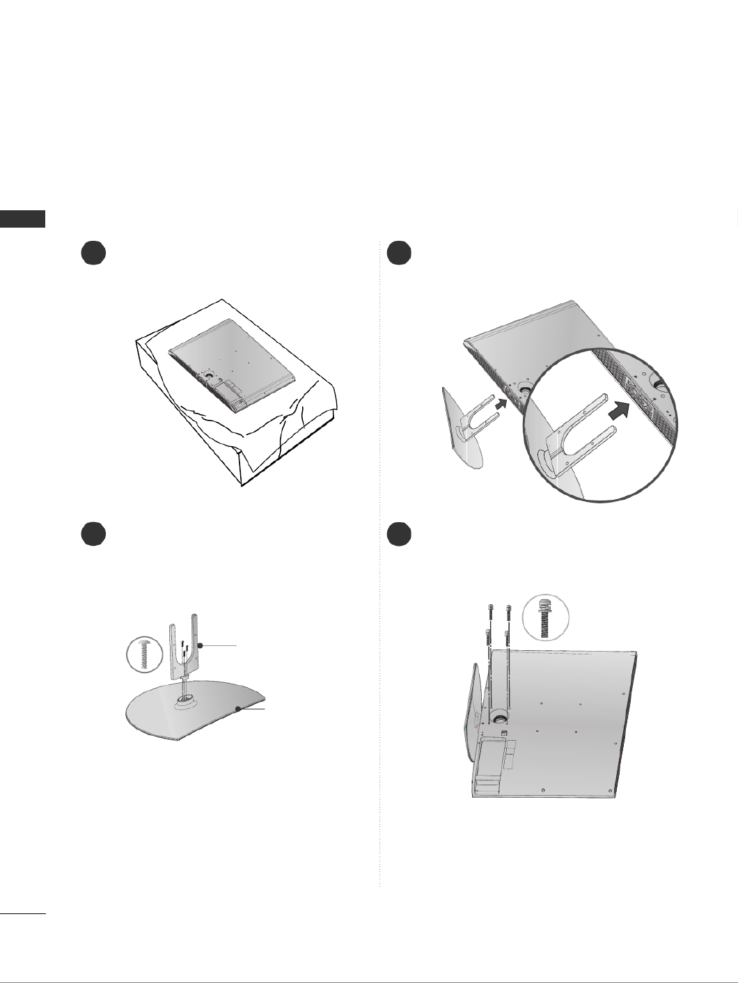
PREPARATION
PREPARATION
1 3
4
Carefully place the TV screen side down on a
cushioned surface to protect the screen from
damage.
2Assemble the parts of the S
S
S
S
St
t
t
t
ta
a
a
a
an
n
n
n
nd
d
d
d
d
B
B
B
B
Bo
o
o
o
od
d
d
d
dy
y
y
y
y with
C
C
C
C
Co
o
o
o
ov
v
v
v
ve
e
e
e
er
r
r
r
r
B
B
B
B
Ba
a
a
a
as
s
s
s
se
e
e
e
e of the TV.
Assemble the TV as shown.
Fix the 4 bolts securely using the holes in the
back of the TV.
Stand Body
Cover Base
STAND INSTALLATION
(Only 32LG6***)
■
Image shown may differ from your TV.
When assembling the desk type stand, check whether the bolt is fully tightened.
(If not tightened fully, the product can tilt forward after the product installation.) If you tighten the bolt with
excessive force, the bolt can deviate from abrasion of the tightening part of the bolt.
9
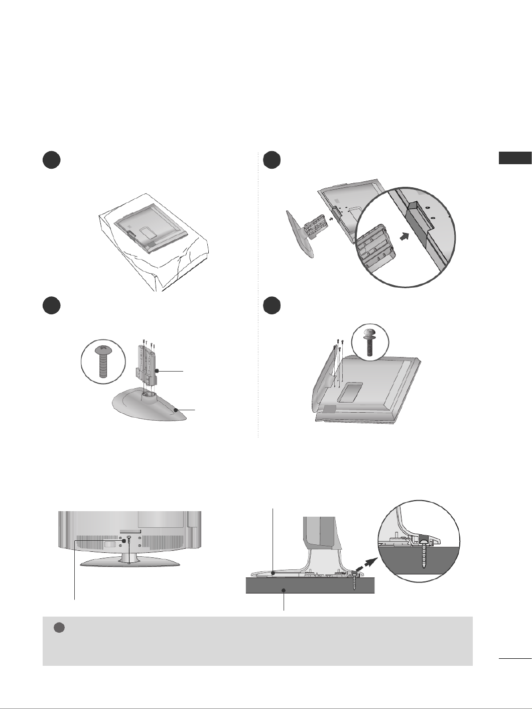
PREPARATION
1 3
4
Carefully place the TV screen side down on a
cushioned surface to protect the screen from
damage.
2Assemble the parts of the S
S
S
S
St
t
t
t
ta
a
a
a
an
n
n
n
nd
d
d
d
d
B
B
B
B
Bo
o
o
o
od
d
d
d
dy
y
y
y
y with
the
C
C
C
C
Co
o
o
o
ov
v
v
v
ve
e
e
e
er
r
r
r
r
B
B
B
B
Ba
a
a
a
as
s
s
s
se
e
e
e
e of the TV.
Assemble the TV as shown.
Fix the 4 bolts securely using the holes in the
back of the TV.
Stand Body
Cover Base
(
Only
26/32/37LG3***)
ATTACHING THE TV TO A DESK (Only 26/32/42LG3***, 32/42LG5***)
The TV must be attached to desk so it cannot be pulled in a forward/backward direction, potentially causing
injury or damaging the product. Use only an attached screw.
1-Screw
(provided as parts of the product)
Desk
Stand
WARNING
!
G To prevent TV from falling over, the TV should be securely attached to the floor/wall per installation
instructions. Tipping, shaking, or rocking the machine may cause injury.

10
PREPARATION
PREPARATION
PLEASE SET IT UP CAREFULLY SO THE PRODUCT
DOESN’T FALL OVER.
2
1
AYou should purchase necessary components to fix the TV to the wall on the market.
APosition the TV close to the wall to avoid the possibility of it falling when pushed.
AThe instructions shown below are a safer way to set up the TV, which is to fix it to the wall, avoiding the
possibility of it falling forwards if pulled. This will prevent the TV from falling forward and causing injury.
This will also prevent the TV from damage. Ensure that children do not climb or hang from the TV.
NOTE
!
G When moving the TV undo the cords first.
G Use a platform or cabinet strong and large enough to support the size and weight of the TV.
G To use the TV safely make sure that the height of the bracket on the wall and on the TV is the same.
2
3
1
1
2
Use the eye-bolts or TV brackets/bolts to fix the product to the wall as shown in the picture.
(If your TV has bolts in the eyebolts, loosen then bolts.)
* Insert the eye-bolts or TV brackets/bolts and tighten them securely in the upper holes.
Secure the wall brackets with the bolts on the wall. Match the height of the bracket that is mounted on the
wall.
3Use a sturdy rope to tie the product. It is safer to tie the rope so it becomes horizontal between
the wall and the product.

11
PREPARATION
BACK COVER FOR WIRE ARRANGEMENT
■
Image shown may differ from your TV.
32/42/47/52LG6***
SWIVEL STAND
This feature is not available for all models.
After installing the TV, you can adjust the TV set manually to the left or right direction by 20 degrees to suit
your viewing position.
Connect the cables as necessary.
To connect additional equipment, see the E
E
E
E
Ex
x
x
x
xt
t
t
t
te
e
e
e
er
r
r
r
rn
n
n
n
na
a
a
a
al
l
l
l
l
E
E
E
E
Eq
q
q
q
qu
u
u
u
ui
i
i
i
ip
p
p
p
pm
m
m
m
me
e
e
e
en
n
n
n
nt
t
t
t
t
S
S
S
S
Se
e
e
e
et
t
t
t
tu
u
u
u
up
p
p
p
p section.
1
2
Align the hole with the tab on the C
C
C
C
CA
A
A
A
AB
B
B
B
BL
L
L
L
LE
E
E
E
E
M
M
M
M
MA
A
A
A
AN
N
N
N
NA
A
A
A
AG
G
G
G
GE
E
E
E
EM
M
M
M
ME
E
E
E
EN
N
N
N
NT
T
T
T
T
C
C
C
C
CL
L
L
L
LI
I
I
I
IP
P
P
P
P.
Turn the C
C
C
C
CA
A
A
A
AB
B
B
B
BL
L
L
L
LE
E
E
E
E
M
M
M
M
MA
A
A
A
AN
N
N
N
NA
A
A
A
AG
G
G
G
GE
E
E
E
EM
M
M
M
ME
E
E
E
EN
N
N
N
NT
T
T
T
T
C
C
C
C
CL
L
L
L
LI
I
I
I
IP
P
P
P
P as shown.
Note: This cable management can be broken by excessive pressure.

12
PREPARATION
PREPARATION
When installing the wall-mounted unit, use the protection cover for desk-type stand installation.
■
Image shown may differ from your TV.
NOT USING THE DESK-TYPE STAND
After removing the protection paper from the
protection cover, adhere it to the TV as shown.
Connect the cables as necessary.
To connect additional equipment, see the
External Equipment Setup section of the manual.
1
Open the C
C
C
C
CA
A
A
A
AB
B
B
B
BL
L
L
L
LE
E
E
E
E
M
M
M
M
MA
A
A
A
AN
N
N
N
NA
A
A
A
AG
G
G
G
GE
E
E
E
EM
M
M
M
ME
E
E
E
EN
N
N
N
NT
T
T
T
T
C
C
C
C
CL
L
L
L
LI
I
I
I
IP
P
P
P
P as
shown and manage the cables.
2
CABLE MANAGEMENT CLIP
Fit the C
C
C
C
CA
A
A
A
AB
B
B
B
BL
L
L
L
LE
E
E
E
E
M
M
M
M
MA
A
A
A
AN
N
N
N
NA
A
A
A
AG
G
G
G
GE
E
E
E
EM
M
M
M
ME
E
E
E
EN
N
N
N
NT
T
T
T
T
C
C
C
C
CL
L
L
L
LI
I
I
I
IP
P
P
P
Pas
shown.
3
26/32/37/42LG3***, 32/42/47LG5***, 42/47/52LG7***
Insert the P
P
P
P
PR
R
R
R
RO
O
O
O
OT
T
T
T
TE
E
E
E
EC
C
C
C
CT
T
T
T
TI
I
I
I
IO
O
O
O
ON
N
N
N
N
C
C
C
C
CO
O
O
O
OV
V
V
V
VE
E
E
E
ER
R
R
R
R into the TV
until clicking sound.
32/42/47/52LG6*** 26/32/37/42LG3***,
32/42/47LG5***, 42/47/52LG7***

13
PREPARATION
WALL MOUNT: HORIZONTAL INSTALLATION
For adequate ventilation allow a clearance of 4” (10cm) all around the TV. We recommend that you
use a wall mounting bracket of LG brand when mounting the TV to a wall.
4 inches
4 inches
4 inches
4 inches
4 inches
DESKTOP PEDESTAL INSTALLATION
AThe TV can be installed in various ways such as on a wall, or on a desktop etc.
A The TV is designed to be mounted horizontally.
Power Supply
Circuit breaker
EARTHING
Ensure that you connect the earth wire to prevent possible
electric shock. If grounding methods are not possible, have a
qualified electrician install a separate circuit breaker.
Do not try to earth the TV by connecting it to telephone
wires, lightening rods or gas pipes.
4 inches
4 inches
4 inches
4 inches
For adequate ventilation allow a clearance of 4” (10cm) all around the TV.

14
PREPARATION
PREPARATION
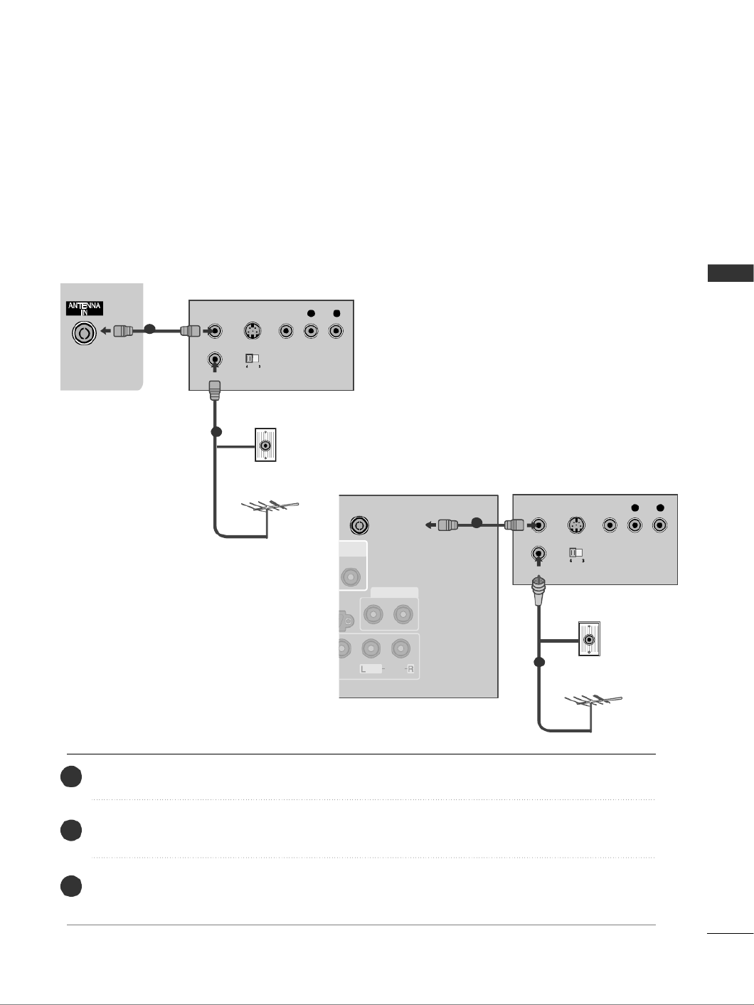
ANTENNA CONNECTION
■For optimum picture quality, adjust antenna direction.
■An antenna cable and converter are not supplied.
■To prevent damage do not connect to the mains outlet until all connections are made between the devices.
Multi-family Dwellings/Apartments
(Connect to wall antenna socket)
Single-family Dwellings /Houses
(Connect to wall jack for outdoor antenna)
Outdoor
Antenna
(VHF, UHF)
Wall
Antenna
Socket
RF Coaxial Wire (75 ohm)
Antenna
UHF
Signal
Amplifier
VHF
■In poor signal areas, to achieve better picture quality it may be necessary to install a signal amplifier to the
antenna as shown above.
■If signal needs to be split for two TVs, use an antenna signal splitter for connection.

15
EXTERNAL EQUIPMENT SETUP
EXTERNAL EQUIPMENT SETUP
HD RECEIVER SETUP
■To avoid damaging any equipment, never plug in any power cords until you have finished connecting all equipment.
■This section on EXTERNAL EQUIPMENT SETUP mainly uses diagrams for the 42LG6***/42LG7*** model.
■
Image shown may differ from your TV.
Connecting with a component cable
1
2
COMPONENT IN
VIDEOAUDIO
1
2
Signal
480i/576i
480p/576p
720p/1080i
1080p
Component
Yes
Yes
Yes
Yes
(50/60Hz only)
HDMI
No
Yes
Yes
Yes
(24Hz/30Hz/50Hz/60Hz)
■This TV can receive Digital RF/Cable signals without an external digital set-top box. However, if you do receive
Digital signals from a digital set-top box or other digital external device, refer to the diagram as shown below.
Connect the video outputs (Y, PB, PR)of the digital set
top box to the
C
C
C
C
CO
O
O
O
OM
M
M
M
MP
P
P
P
PO
O
O
O
ON
N
N
N
NE
E
E
E
EN
N
N
N
NT
T
T
T
T
I
I
I
I
IN
N
N
N
N
V
V
V
V
VI
I
I
I
ID
D
D
D
DE
E
E
E
EO
O
O
O
Ojacks on the TV.
Connect the audio output of the digital set-top box to
the
C
C
C
C
CO
O
O
O
OM
M
M
M
MP
P
P
P
PO
O
O
O
ON
N
N
N
NE
E
E
E
EN
N
N
N
NT
T
T
T
T
I
I
I
I
IN
N
N
N
N
A
A
A
A
AU
U
U
U
UD
D
D
D
DI
I
I
I
IO
O
O
O
O jacks on the TV.
Turn on the digital set-top box.
(Refer to the owner’s manual for the digital set-top box.)
Select C
C
C
C
Co
o
o
o
om
m
m
m
mp
p
p
p
po
o
o
o
on
n
n
n
ne
e
e
e
en
n
n
n
nt
t
t
t
t1
1
1
1
1 input source using the I
I
I
I
IN
N
N
N
N P
P
P
P
PU
U
U
U
UT
T
T
T
T button on the remote control.
If connected to C
C
C
C
CO
O
O
O
OM
M
M
M
MP
P
P
P
PO
O
O
O
ON
N
N
N
N E
E
E
E
EN
N
N
N
N T
T
T
T
T
I
I
I
I
IN
N
N
N
N
2
2
2
2
2input, select
C
C
C
C
Co
o
o
o
om
m
m
m
mp
p
p
p
po
o
o
o
on
n
n
n
ne
e
e
e
en
n
n
n
nt
t
t
t
t
2
2
2
2
2
input source.
2
3
4
1
COMPONENT IN
AUDIO
VIDEO
1
2
12
or

16
EXTERNAL EQUIPMENT SETUP
EXTERNAL EQUIPMENT SETUP
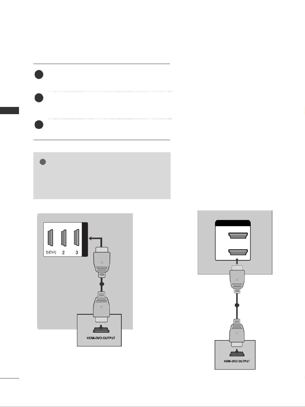
Connecting a set-top box with an HDMI cable
HDMI/DVI IN
1
Connect the digital set-top box to
H
H
H
H
HD
D
D
D
DM
M
M
M
MI
I
I
I
I/
/
/
/
/D
D
D
D
DV
V
V
V
VI
I
I
I
I
I
I
I
I
IN
N
N
N
N
1
1
1
1
1,
H
H
H
H
HD
D
D
D
DM
M
M
M
MI
I
I
I
I
I
I
I
I
IN
N
N
N
N
2
2
2
2
2,
H
H
H
H
HD
D
D
D
DM
M
M
M
MI
I
I
I
I
I
I
I
I
IN
N
N
N
N
3
3
3
3
3
or
H
H
H
H
HD
D
D
D
DM
M
M
M
MI
I
I
I
I
I
I
I
I
IN
N
N
N
N
4
4
4
4
4(only
32/42/47/52LG6***) jack on the TV.
Turn on the digital set-top box.
(Refer to the owner’s manual for the digital set-top box.)
Select H
H
H
H
HD
D
D
D
DM
M
M
M
MI
I
I
I
I1
1
1
1
1, H
H
H
H
HD
D
D
D
DM
M
M
M
MI
I
I
I
I2
2
2
2
2, H
H
H
H
HD
D
D
D
DM
M
M
M
MI
I
I
I
I3
3
3
3
3
or H
H
H
H
HD
D
D
D
DM
M
M
M
MI
I
I
I
I4
4
4
4
4(only
32/42/47/52LG6***) input source using the I
I
I
I
IN
N
N
N
NP
P
P
P
PU
U
U
U
UT
T
T
T
T
button on the remote control.
2
3
1
HDMI/DVI IN
2
1
(DVI)
1
or

17
EXTERNAL EQUIPMENT SETUP
Connecting with an HDMI to DVI cable
AV OUT
VIDEOAUDIO
B IN
HDMI/DVI IN
AUDIO
(RGB/DVI)
RGB IN
1
2
Connect the digital set-top box to H
H
H
H
HD
D
D
D
DM
M
M
M
MI
I
I
I
I/
/
/
/
/D
D
D
D
DV
V
V
V
VI
I
I
I
I
I
I
I
I
IN
N
N
N
N
1
1
1
1
1
jack on the TV.
Connect the audio output of the digital set-top box to the A
A
A
A
AU
U
U
U
UD
D
D
D
DI
I
I
I
IO
O
O
O
O
(
(
(
(
(R
R
R
R
RG
G
G
G
GB
B
B
B
B/
/
/
/
/D
D
D
D
DV
V
V
V
VI
I
I
I
I)
)
)
)
)
jack on the TV.
Turn on the digital set-top box. (Refer to the owner’s manual for the digital set-top box.)
Select H
H
H
H
HD
D
D
D
DM
M
M
M
MI
I
I
I
I1
1
1
1
1input source using the I
I
I
I
IN
N
N
N
NP
P
P
P
PU
U
U
U
UT
T
T
T
T button on the remote control.
2
3
4
1
(C
O
COMPONENT IN
L R
AUDIO
VIDEO
Y P
B
P
R
A
2
HDMI/DVI IN
RGB IN
AUDIO
(RGB/DVI)
RGB(PC)
1
2
1
(DVI)
12
or

18
EXTERNAL EQUIPMENT SETUP
EXTERNAL EQUIPMENT SETUP
DVD SETUP
Connecting with a component cable
1
2
COMPONENT IN
VIDEOAUDIO
Component Input ports
To achieve better picture quality, connect a DVD player to the component input ports as shown below.
Component ports on the TV
Y PBPR
Video output ports
on DVD player
Y
Y
Y
Y
PB
B-Y
Cb
Pb
PR
R-Y
Cr
Pr
1
2
Connect the video outputs (Y, PB R, P )of the DVD to the C
C
C
C
CO
O
O
O
OM
M
M
M
MP
P
P
P
PO
O
O
O
ON
N
N
N
NE
E
E
E
EN
N
N
N
NT
T
T
T
T
I
I
I
I
IN
N
N
N
N
V
V
V
V
VI
I
I
I
ID
D
D
D
DE
E
E
E
EO
O
O
O
Ojacks on the TV.
Connect the audio outputs of the DVD to the
C
C
C
C
CO
O
O
O
OM
M
M
M
MP
P
P
P
PO
O
O
O
ON
N
N
N
NE
E
E
E
EN
N
N
N
NT
T
T
T
T
I
I
I
I
IN
N
N
N
N
A
A
A
A
AU
U
U
U
UD
D
D
D
DI
I
I
I
IO
O
O
O
O jacks on the TV.
Turn on the DVD player, insert a DVD.
Select C
C
C
C
Co
o
o
o
om
m
m
m
mp
p
p
p
po
o
o
o
on
n
n
n
ne
e
e
e
en
n
n
n
nt
t
t
t
t1
1
1
1
1 input source using the I
I
I
I
IN
N
N
N
NP
P
P
P
PU
U
U
U
UT
T
T
T
T button on the remote control.
If connected to
C
C
C
C
CO
O
O
O
OM
M
M
M
MP
P
P
P
PO
O
O
O
ON
N
N
N
NE
E
E
E
EN
N
N
N
NT
T
T
T
T
I
I
I
I
IN
N
N
N
N
2
2
2
2
2input, select
C
C
C
C
Co
o
o
o
om
m
m
m
mp
p
p
p
po
o
o
o
on
n
n
n
ne
e
e
e
en
n
n
n
nt
t
t
t
t
2
2
2
2
2
input source.
Refer to the DVD player's manual for operating instructions.
2
3
4
5
1
COMPONENT IN
AUDIO
VIDEO
1
2
12
or

19
EXTERNAL EQUIPMENT SETUP
Connecting with a S-Video cable
A
A
A
AAV IN
V IN
V IN
V IN
V IN
L R
S-VIDEOVIDEO
O UT
SW CH
ANT IN
ANT OUT
Connect the S-VIDEO output of the DVD to the
S
S
S
S
S -
-
-
-
-
V
V
V
V
VI
I
I
I
ID
D
D
D
DE
E
E
E
EO
O
O
O
O input on the TV.
Connect the audio outputs of the DVD to the A
A
A
A
AU
U
U
U
UD
D
D
D
DI
I
I
I
IO
O
O
O
O
input jacks on the TV.
Turn on the DVD player, insert a DVD.
Select
A
A
A
A
A V
V
V
V
Vinput source using the I
I
I
I
IN
N
N
N
NP
P
P
P
PU
U
U
U
UT
T
T
T
T button on
the remote control.
Refer to the DVD player's manual for operating instruc-
tions.
2
3
4
5
1
12
20
EXTERNAL EQUIPMENT SETUP
EXTERNAL EQUIPMENT SETUP
HDMI/DVI IN
Connecting the HDMI cable
Connect the HDMI output of the DVD to the
H
H
H
H
HD
D
D
D
DM
M
M
M
MI
I
I
I
I/
/
/
/
/D
D
D
D
DV
V
V
V
VI
I
I
I
I
I
I
I
I
IN
N
N
N
N
1
1
1
1
1, H
H
H
H
HD
D
D
D
DM
M
M
M
MI
I
I
I
I
I
I
I
I
IN
N
N
N
N
2
2
2
2
2, H
H
H
H
HD
D
D
D
DM
M
M
M
MI
I
I
I
I
I
I
I
I
IN
N
N
N
N
3
3
3
3
3
or H
H
H
H
HD
D
D
D
DM
M
M
M
MI
I
I
I
I
I
I
I
I
IN
N
N
N
N
4
4
4
4
4(only 32/42/47/52LG6***) jack on the TV.
Select H
H
H
H
HD
D
D
D
DM
M
M
M
M I
I
I
I
I1
1
1
1
1, H
H
H
H
HD
D
D
D
DM
M
M
M
M I
I
I
I
I2
2
2
2
2, H
H
H
H
HD
D
D
D
DM
M
M
M
MI
I
I
I
I3
3
3
3
3
or H
H
H
H
HD
D
D
D
DM
M
M
M
M I
I
I
I
I4
4
4
4
4(only
32/42/47/52LG6***) input source using the I
I
I
I
IN
N
N
N
NP
P
P
P
PU
U
U
U
UT
T
T
T
T
button on the remote control.
Refer to the DVD player's manual for operating
instructions.
2
3
1
1
G
G
G
G
GThe TV can receive video and audio signals simultane-
ously when using a HDMI cable.
G
G
G
G
GIf the DVD does not support Auto HDMI, you must set
the output resolution appropriately.
NOTE
!
HDMI/DVI IN
2
1
(DVI)
1
or
21
EXTERNAL EQUIPMENT SETUP
VCR SETUP
■To avoid picture noise (interference), allow adequate distance between the VCR and TV.
■Typically a frozen still picture from a VCR. If 4:3 picture format is used for an extended period the fixed
images on the sides of the screen may remain visible.
OUTPUT
SWITCH
ANT IN
R
S-VIDEO VIDEO
ANT OUT L
Wall Jack
Antenna
1
Connecting with a RF Cable
Connect the
A
A
A
A
AN
N
N
N
NT
T
T
T
T
O
O
O
O
OU
U
U
U
UT
T
T
T
T socket of the VCR to the
A
A
A
A
AN
N
N
N
NT
T
T
T
TE
E
E
E
EN
N
N
N
NN
N
N
N
NA
A
A
A
A
I
I
I
I
IN
N
N
N
N socket on the TV.
Connect the antenna cable to the
A
A
A
A
AN
N
N
N
NT
T
T
T
T
I
I
I
I
IN
N
N
N
N socket of the VCR.
Press the P
P
P
P
PL
L
L
L
LA
A
A
A
AY
Y
Y
Y
Y button on the VCR and match the appropriate channel between the TV and VCR for
viewing.
2
3
1
IN
ERVICE)
VIDEO
AUDIO
/MONO
VIDEO OUT
AUDIO OUT
ANTENNA IN
OUTPUT
SWITCH
ANT IN
R
S-VIDEO VIDEOANT OUT L
Wall Jack
Antenna
1
2
or
2
23
EXTERNAL EQUIPMENT SETUP
AV OUTPUT SETUP
The TV has a special signal output capability which allows you
to hook up the second TV or monitor.
Connect the second TV or monitor to the TV’s A
A
A
A
AV
V
V
V
V
O
O
O
O
OU
U
U
U
UT
T
T
T
T
jacks.
See the Operating Manual of the second TV or monitor
for further details regarding that device’s input settings.
G
G
G
G
GOnly Digital, Analogue mode can be used for AV out.
Component, RGB, HDMI input sources cannot be used for
AV out.
G
G
G
G
GWe recommend to use the AV OUT jacks for VCR recording.
NOTE
!
2
1
AUDIO
(RGB/DVI)
RGB IN
AV OUT
VIDEOAUDIO
L R
S-VIDEO
VIDEO
1
RS-232C IN
(CONTROL & SERVICE)
OPTICAL
AV IN 1
I)
R
AUDIO
DIGITAL
AUDIO OUT
VIDEO
AUD
/M
ANTENNA IN
VIDEO OUT
AUDIO OUT
L R
S-VIDEO
VIDEO
1
or

24
EXTERNAL EQUIPMENT SETUP
EXTERNAL EQUIPMENT SETUP
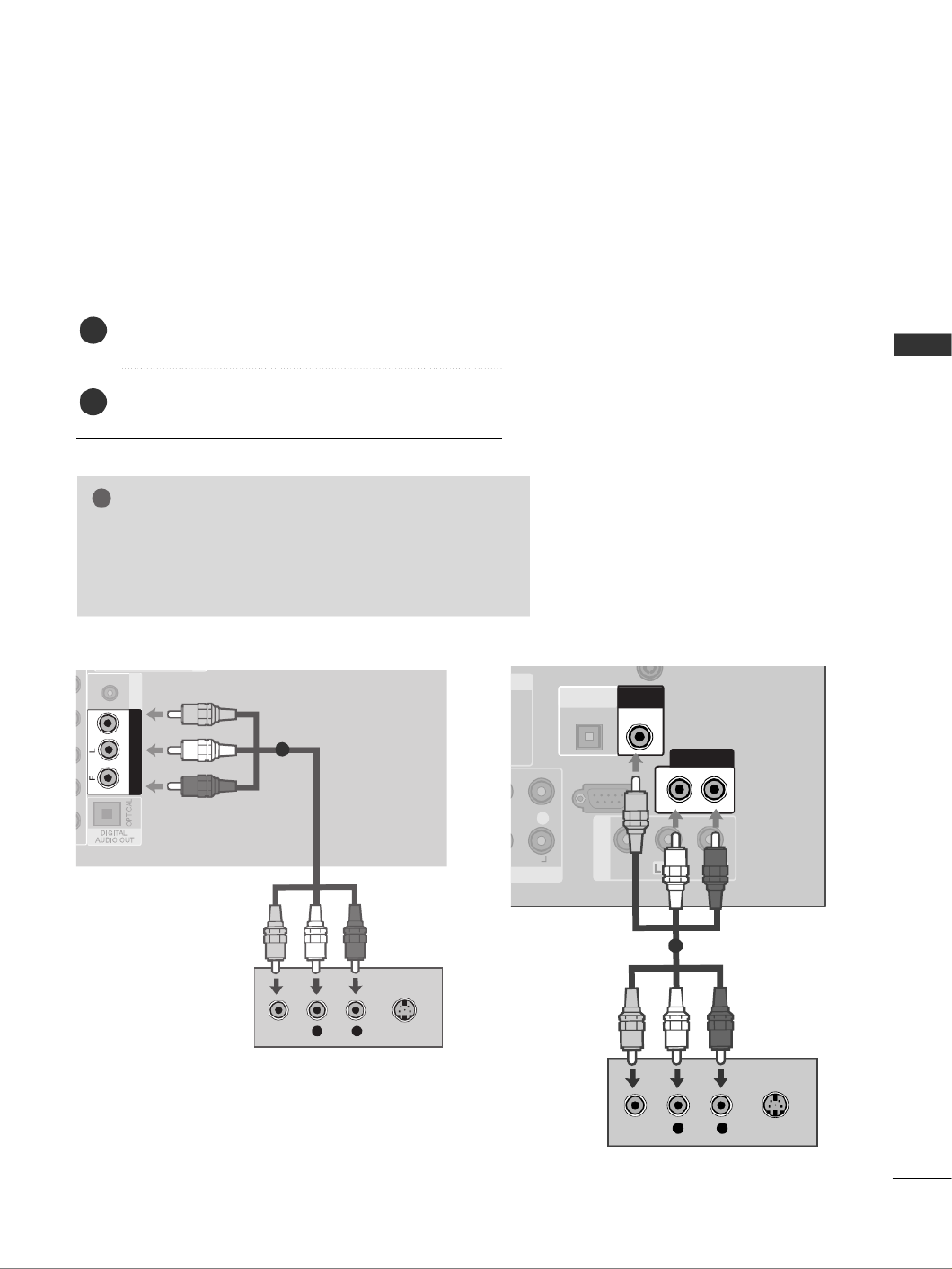
GDo not look into the optical output port. Looking at the
laser beam may damage your vision.
CAUTION
Connect one end of an optical cable to the TV Digital
Audio (Optical)Output port.
Connect the other end of the optical cable to the digi-
tal audio (Optical)input on the audio equipment.
Set the “TV Speaker option - Off ” in the AUDIO
menu.(Gp
p
p
p
p.
.
.
.
.8
8
8
8
84
4
4
4
4). Refer to the external audio equipment
instruction manual for operation.
2
3
1
1
2
DIGITAL AUDIO OUT SETUP
Sending the TV’s audio signal to external audio equipment via the Digital Audio Output (Optical) port.
G
G
G
G
GWhen connecting with external audio equipments, such as
amplifiers or speakers, please turn the TV speakers off.
NOTE
!
RS-232C IN
(CONTROL & SERVICE)
AV IN 1
IN
AUDIO
(RGB/DVI)
ONENT IN
L
R
R
AUDIO
VIDEO
AUDIO
/MONO
VIDEO OUT
AUDIO OUT
OPTICAL
DIGITAL
AUDIO OUT
1
2
1
2
or

26
EXTERNAL EQUIPMENT SETUP
EXTERNAL EQUIPMENT SETUP
PC SETUP
This TV provides Plug and Play capability, meaning that the PC adjusts automatically to the TV's settings.
Connecting with a D-sub 15 pin cable
2
AV OUT
VIDEOAUDIO
HDM DVI N
RGB IN
(PC)
RGB IN
AUDIO
(RGB/DVI)
RGB IN
AUDIO RGB OUTPUT
1
2
4
Connect the RGB output of the PC to the
R
R
R
R
RG
G
G
G
GB
B
B
B
B
I
I
I
I
IN
N
N
N
N
(
(
(
(
(P
P
P
P
PC
C
C
C
C)
)
)
)
)
jack on the TV.
Connect the PC audio output to the A
A
A
A
AU
U
U
U
UD
D
D
D
DI
I
I
I
IO
O
O
O
O
(
(
(
(
(R
R
R
R
RG
G
G
G
GB
B
B
B
B/
/
/
/
/D
D
D
D
DV
V
V
V
VI
I
I
I
I)
)
)
)
) jack on the TV.
Turn on the PC and the TV
Select R
R
R
R
RG
G
G
G
GB
B
B
B
B input source using the INPUT button on
the remote control.
2
3
1
RS
(CONTR
OPTIC
ONENT IN
L R
AUDIO
DIGIT
AUDIO
HDMI/DVI IN
2
1
(DVI)
RGB IN
AUDIO
(RGB/DVI)
RGB(PC)
1
2
RGB OUTPUT AUDIO
12
or

27
EXTERNAL EQUIPMENT SETUP
AV OUT
VIDEOAUDIO
B IN
HDMI/DVI IN
AUDIO
(RGB/DVI)
RGB IN
AUDIO DVI-PC OUTPUT
Connecting with a HDMI to DVI cable
1
2
4
Connect the DVI output of the PC to the H
H
H
H
HD
D
D
D
DM
M
M
M
MI
I
I
I
I/
/
/
/
/D
D
D
D
DV
V
V
V
VI
I
I
I
I
I
I
I
I
IN
N
N
N
N1
1
1
1
1
jack on the TV.
Connect the PC audio output to the A
A
A
A
AU
U
U
U
UD
D
D
D
DI
I
I
I
IO
O
O
O
O
(
(
(
(
(R
R
R
R
RG
G
G
G
GB
B
B
B
B/
/
/
/
/D
D
D
D
DV
V
V
V
VI
I
I
I
I)
)
)
)
)jack on the TV.
Turn on the PC and the TV.
Select H
H
H
H
HD
D
D
D
DM
M
M
M
MI
I
I
I
I1
1
1
1
1input source using the INPUT button
on the remote control.
2
3
1
1
(DVI)
RS-232C IN
(CONTROL & SERVICE)
OPTICAL
AV IN 1
COMPONENT IN
VIDEO
LY P
B
P
R
R
AUDIO
DIGITAL
AUDIO OUT
VIDEO
VIDEO OU
2
HDMI/DVI IN
RGB IN
AUDIO
(RGB/DVI)
RGB(PC)
1
2
DVI-PC OUTPUT AUDIO
12
or

28
EXTERNAL EQUIPMENT SETUP
EXTERNAL EQUIPMENT SETUP
NOTE
!
G
To enjoy vivid picture and sound, connect a PC to the
TV.
G
Avoid keeping a fixed image on the set’s screen for
prolonged periods of time. The fixed image may
become permanently imprinted on the screen; use a
screen saver when possible.
G
Connect the PC to the RGB (PC) or HDMI IN (or
HDMI/DVI IN) port of the TV; change the resolution.
G
There may be interference relating to resolution, ver-
tical pattern, contrast or brightness in PC mode.
Change the PC mode to another resolution or change
the refresh rate to another rate or adjust the bright-
ness and contrast on the menu until the picture is
clear. If the refresh rate of the PC graphic card can not
be changed, change the PC graphic card or consult
the manufacturer of the PC graphic card.
G
The synchronization input waveform for Horizontal
and Vertical frequencies are separate.
G
Connect the signal cable from the monitor output
port of the PC to the RGB (PC) port of the TV or the
signal cable from the HDMI output port of the PC to
the HDMI IN (or HDMI/DVI IN) port on the TV.
G
Connect the audio cable from the PC to the Audio
input on the TV. (Audio cables are not included with
the TV).
G
If using a sound card, adjust PC sound as required.
G
This TV uses a VESA Plug and Play Solution. The TV
provides EDID data to the PC system with a DDC pro-
tocol. The PC adjusts automatically when using this
TV.
G
DDC protocol is preset for RGB (Analogue RGB),
HDMI (Digital RGB) mode.
G
If required, adjust the settings for Plug and Play func-
tionality
G
If the graphic card on the PC does not output ana-
logue and digital RGB simultaneously, connect only
one of either RGB or HDMI IN (or HDMI/DVI IN) to
display the PC output on the TV.
G
If graphic card on the PC does output analogue and
digital RGB simultaneously, set the TV to either RGB
or HDMI; (the other mode is set to Plug and Play
automatically by the TV.)
G
DOS mode may not work depending on the video
card if you use a HDMI to DVI cable.
G
If you use too long an RGB-PC cable, there may be
interference on the screen. We recommend using
under 5m of cable. This provides the best picture
quality.
G
When an unsupported resolution or graphic card is
used on the PC, it may cause some errors.
Supported Display Resolution
RGB-PC, HDMI-PC mode
70.08
59.94
60.31
60.00
70.00
59.87
59.8
59.6
60.0
59.988
31.468
31.469
37.879
48.363
56.470
47.78
47.72
47.56
63.595
66.647
720x400
Resolution Horizontal
Frequency(kHz) Vertical
Frequency(Hz)
640x480
800x600
1024x768
1280x768
1360x768
1366x768
1280x1024
1920x1080
Only 32LG60F
*
, 42/47/52LG6
***
, 32/42/47LG5
***, 42/47/52LG7***

29
EXTERNAL EQUIPMENT SETUP
1
MENU
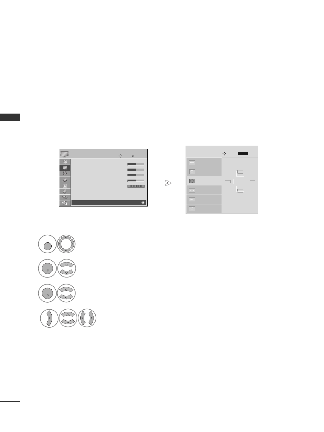
Screen Setup for PC mode
Returns Position, Size and Phase to the factory default settings.
This function works in the following mode : RGB[PC].
Screen Reset
Select P
P
P
P
PI
I
I
I
IC
C
C
C
CT
T
T
T
TU
U
U
U
UR
R
R
R
R E
E
E
E
E.
Select S
S
S
S
SC
C
C
C
CR
R
R
R
R E
E
E
E
E E
E
E
E
EN
N
N
N
N.
3
Select R
R
R
R
Re
e
e
e
es
s
s
s
se
e
e
e
et
t
t
t
t.
To Set
Auto Config.
SCREEN
Move
Prev.
RETURN
Resolution
Position
Size
Phase
Reset
G
OK
Move
• Contrast 50
• Brightness 50
• Sharpness 50
• Colour 50
• Tint 0
• Advanced Control
• Picture Reset
PICTURE
E
Screen
2
OK
OK
R G
• Press the M
M
M
M
ME
E
E
E
EN
N
N
N
NU
U
U
U
U button to return to normal TV viewing.
• Press the R
R
R
R
RE
E
E
E
ET
T
T
T
TU
U
U
U
UR
R
R
R
RN
N
N
N
N
button to move to the previous menu screen.
Select Y
Y
Y
Y
Y e
e
e
e
e s
s
s
s
s.
Run R
R
R
R
Re
e
e
e
es
s
s
s
se
e
e
e
et
t
t
t
t.
4
OK
5
OK
30
EXTERNAL EQUIPMENT SETUP
EXTERNAL EQUIPMENT SETUP
If the picture is not clear after auto adjustment and especially if characters are still trembling, adjust the
picture phase manually.
This function works in the following mode : RGB[PC].
Adjustment for screen Position, Size, Phase
Select P
P
P
P
PI
I
I
I
IC
C
C
C
CT
T
T
T
TU
U
U
U
UR
R
R
R
RE
E
E
E
E.
Select S
S
S
S
SC
C
C
C
CR
R
R
R
R E
E
E
E
E E
E
E
E
E N
N
N
N
N.
Select P
P
P
P
Po
o
o
o
os
s
s
s
si
i
i
i
it
t
t
t
ti
i
i
i
io
o
o
o
on
n
n
n
n, S
S
S
S
Si
i
i
i
iz
z
z
z
ze
e
e
e
e
or P
P
P
P
Ph
h
h
h
h a
a
a
a
a s
s
s
s
s e
e
e
e
e.
Make appropriate adjustments.
Auto Config.
Resolution
Position
G
Size
Phase
Reset
GF
D
E
OK
Move
• Contrast 50
• Brightness 50
• Sharpness 50
• Colour 50
• Tint 0
• Advanced Control
• Picture Reset
PICTURE
E
Screen
SCREEN
Move
Prev.
1
MENU
3
4
2
OK
OK
R G
• Press the M
M
M
M
ME
E
E
E
EN
N
N
N
NU
U
U
U
U button to return to normal TV viewing.
• Press the R
R
R
R
RE
E
E
E
ET
T
T
T
TU
U
U
U
UR
R
R
R
RN
N
N
N
N button to move to the previous menu screen.
RETURN
31
EXTERNAL EQUIPMENT SETUP
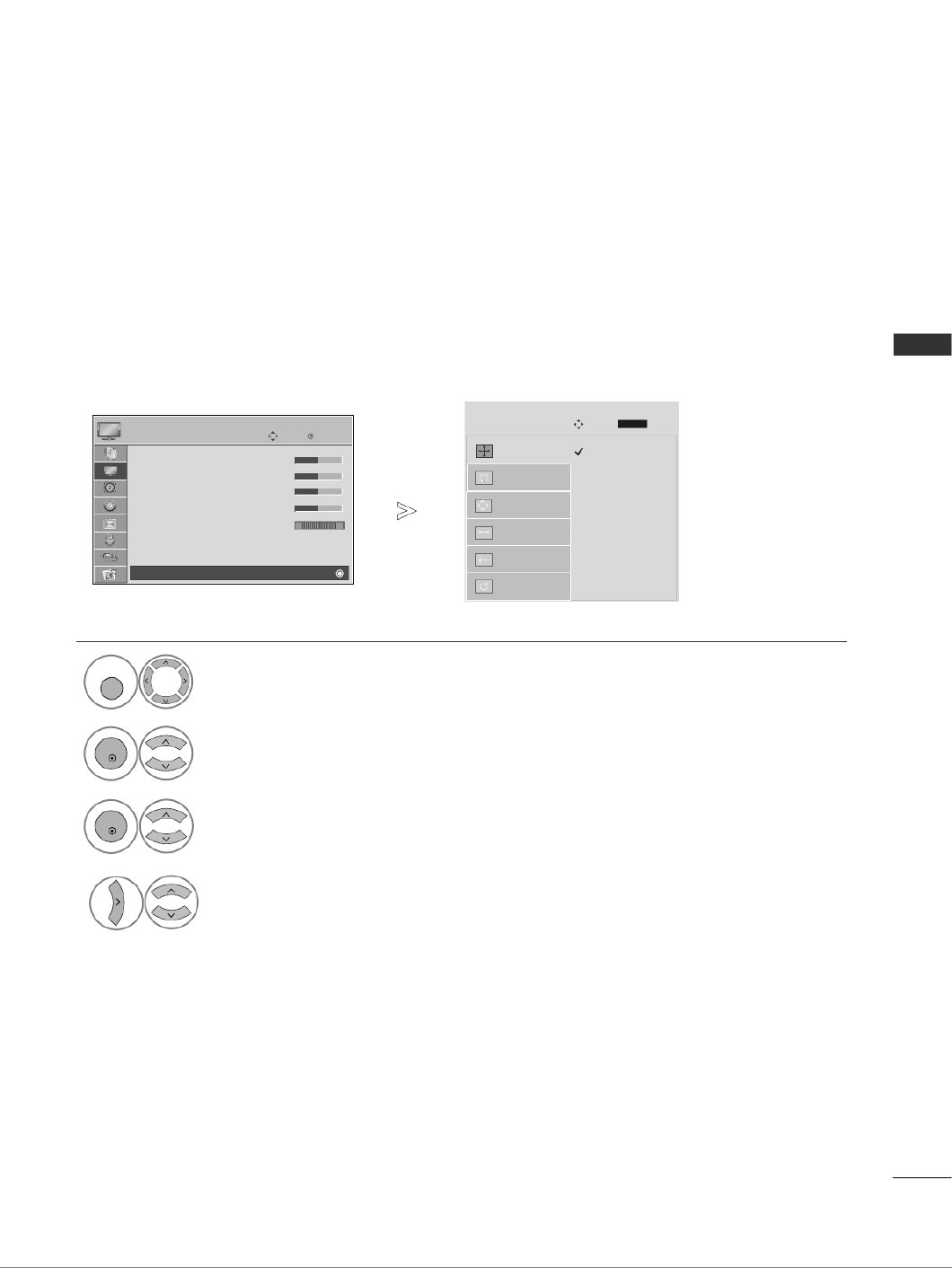
To view a normal picture, match the resolution of RGB mode and selection of PC mode.
This function works in the following mode:
RGB[PC](1024/1280/1360/1366x768, 60Hz)
Selecting Resolution
Select P
P
P
P
PI
I
I
I
IC
C
C
C
CT
T
T
T
TU
U
U
U
UR
R
R
R
RE
E
E
E
E.
Select S
S
S
S
SC
C
C
C
CR
R
R
R
RE
E
E
E
EE
E
E
E
EN
N
N
N
N.
Select R
R
R
R
Re
e
e
e
es
s
s
s
so
o
o
o
ol
l
l
l
lu
u
u
u
ut
t
t
t
ti
i
i
i
io
o
o
o
on
n
n
n
n.
Select the desired resolution.
Auto Config.
Resolution
G
Position
Size
Phase
Reset
OK
Move
• Contrast 50
• Brightness 50
• Sharpness 50
• Colour 50
• Tint 0
• Advanced Control
• Picture Reset
PICTURE
E
Screen
SCREEN
Move
Prev.
1
MENU
3
4
2
OK
OK
R G
• Press the M
M
M
M
M E
E
E
E
EN
N
N
N
N U
U
U
U
U button to return to normal TV viewing.
• Press the R
R
R
R
RE
E
E
E
ET
T
T
T
TU
U
U
U
U R
R
R
R
RN
N
N
N
N button to move to the previous menu screen.
RETURN
1024 x 768
1280 x 768
1360 x 768
1366 x 768

100
APPENDIX
APPENDIX
MAINTENANCE
Early malfunctions can be prevented. Careful and regular cleaning can prolong the life of your new TV.
Caution: Be sure to switch the power off and unplug the power cord before you begin any cleaning.
Cleaning the Screen
A good way to keep the dust off your screen for a while is to wet a soft cloth in a mixture of lukewarm water
and a little fabric softener or dish washing detergent. Wring the cloth until it is almost dry, and then use it
to wipe the screen.
Ensure there is no excess water on the screen. Allow any water or dampness to evaporate before switching on.
Cleaning the Cabinet
ATo remove dirt or dust, wipe the cabinet with a soft, dry, lint-free cloth.
ADo not to use a wet cloth.
Extended Absence
GIf you expect to leave your TV dormant for prolonged periods (such as a holiday), unplug the power
cord to protect against possible damage from lightning or power surges.
CAUTION
2
1

101
APPENDIX
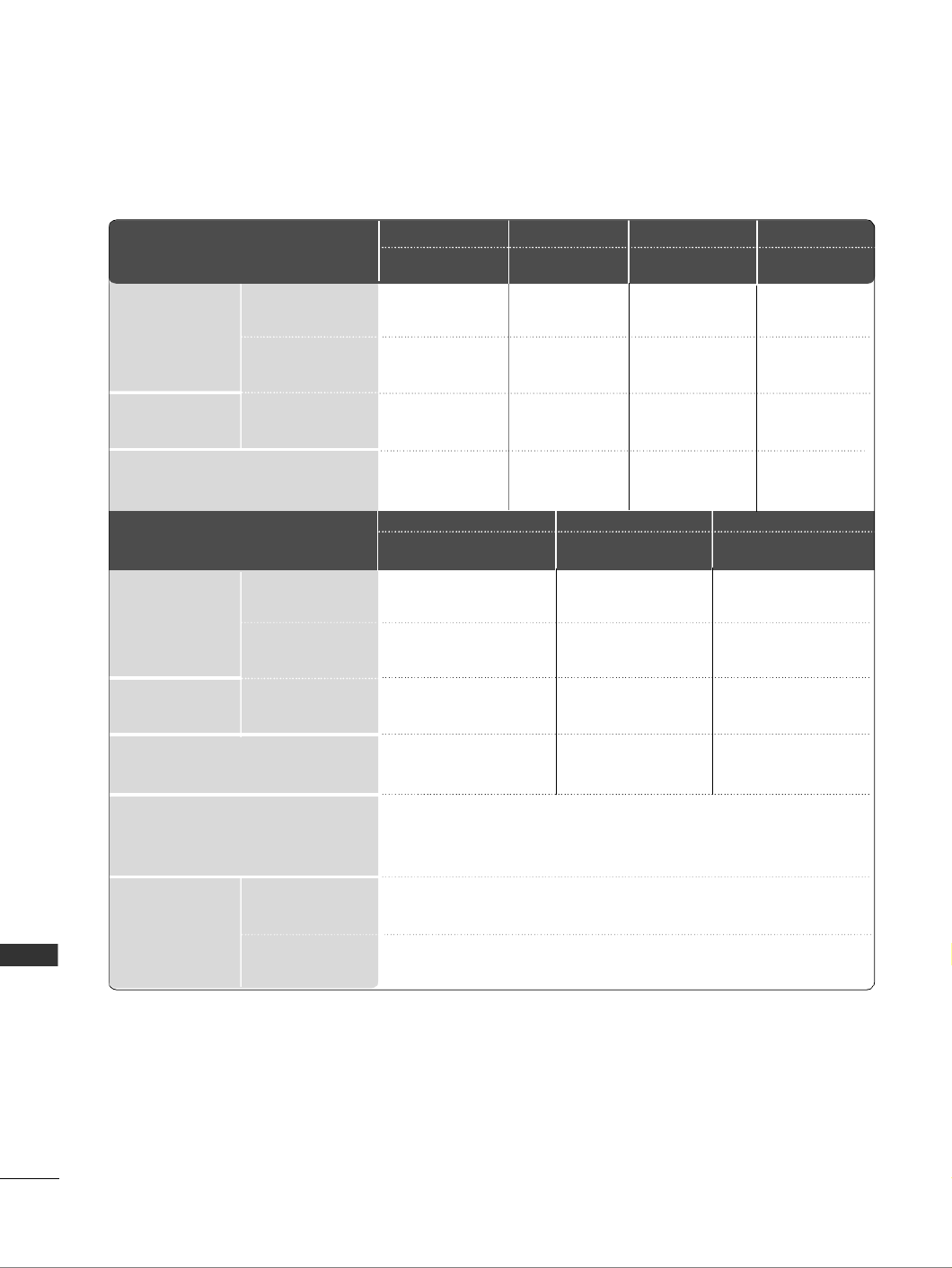
PRODUCT SPECIFICATIONS
■The specifications shown above may be changed without prior notice for quality improvement.
1037.8 x 794.6 x 379.5 mm
40.9x 31.3 x 14.9 inches
1037.8x 747x 80.8mm
40.9 x 29.4 x 3.2 inches
24.1 kg / 53.1 lbs
20.4 kg / 45 lbs
AC100-240V~ 50/60Hz
MODELS
Dimensions
(Width x Height
x Depth)
Weight
Operating Temperature
Operating Humidity
Storage Temperature
Storage Humidity
Environment
condition
Power requirement
Television System
Program Coverage
External Antenna Impedance
PAL B/G, DVB-T
VHF 0-12, UHF 20-75, CATV 02-44, DTV 06-12, 27-69
75 ohm
32 ~ 104°F (0 ~ 40°C)
Less than 80%
-4 ~ 140°F (-20 ~ 60°C)
Less than 85%
with stand
without stand
with stand
without stand
Dimensions
(Width x Height
x Depth)
Weight
Power requirement
with stand
without stand
with stand
without stand
32LG6 ***
32LG60UD-AA
32LG60FD-AC
42LG6 ***
42LG60FD-AA
MODELS
805.6 x 626 x 333 mm
31.7 x 24.6 x 13.1 inches
805.6x 587.4x 96.2mm
31.7 x 23.1 x 3.7 inches
14.4 kg / 31.7 lbs
12.2 kg / 26.9 lbs
AC100-240V~ 50/60Hz
1152.8 x 868.6 x 434.5 mm
45.4 x 34.2 x 17.1 inches
1152.8 x 820.8 x 79 mm
45.4 x 32.3x 3.1 inches
32.8 kg / 72.3 lbs
27.2 kg / 60 lbs
AC100-240V~ 50/60Hz
47LG60 **/
47LG65 **
47LG65YD-AC
47LG60FD-AA
1280.1 x 944.7 x 430 mm
50.4 x 37.2x 16.9inches
1280.1 x 896 x 89 mm
50.4x 35.5 x 3.5 inches
45 kg / 99.2 lbs
38.1kg / 84lbs
AC100-240V~ 50/60Hz
52LG6***
52LG65YD-AC
52LG65YD-AJ
Dimensions
(Width x Height
x Depth)
Weight
Power requirement
with stand
without stand
with stand
without stand
MODELS
1132 x 853.8 x 413.5 mm
44.6 x 33.6 x 16.3 inches
1132 x 807.8 x 44.7 mm
44.6 x 31.8x 1.7 inches
28 kg / 61.7 lbs
24 kg / 52.9 lbs
AC100-240V~ 50/60Hz
47LG61 **
47LG61YD-AC
47LG61YD-AJ
1037.8 x 798 x 378 mm
40.9x 31.4 x 14.9 inches
1037.8x 746.2x 45mm
40.9 x 29.4 x 1.8 inches
21.3 kg / 47 lbs
18 kg / 39.7 lbs
AC100-240V~ 50/60Hz
42LG61 **
42LG61YD-AC
42LG61YD-AJ
1026.2 x 734.0 x 293.4 mm
40.4 x 28.8 x 11.5 inches
1026.2 x 687.9 x 111.8 mm
40.4 x 27.0 x 4.4 inches
21.7 kg / 47.8 lbs
19.1 kg / 42.1 lbs
AC100-240V~ 50/60Hz
1140.4 x 820.1 x 342.9 mm
44.8 x 32.2 x 13.5 inches
1140.4 x 764.8 x 129.0 mm
44.8 x 30.1 x 5.0 inches
30.1 kg / 66.3 lbs
25.4 kg / 55.9 lbs
AC100-240V~ 50/60Hz
42LG7***
42LG70YD-AA
42LG70YD-AG
47LG7***
47LG70YD-AA
47LG70YD-AG
1284.4 x 898.6 x 342.9 mm
50.5 x 35.3 x 13.5 inches
1284.4 x 844.6 x 129.5 mm
50.5 x 33.2 x 5.0 inches
39.9 kg / 87.9 lbs
35.2kg / 77.6lbs
AC100-240V~ 50/60Hz
52LG7 ***
52LG70YD-AA
52LG70YD-AG
102
APPENDIX
APPENDIX
■The specifications shown above may be changed without prior notice for quality improvement.
MODELS
Dimensions
(Width x Height x Depth)
Weight
Operating Temperature
Operating Humidity
Storage Temperature
Storage Humidity
Environment condition
Power requirement
Television System
Program Coverage
External Antenna Impedance
PAL B/G, DVB-T
VHF 0-12, UHF 20-75, CATV 02-44, DTV 06-12, 27-69
75 ohm
32 ~ 104°F (0 ~ 40°C)
Less than 80%
-4 ~ 140°F (-20 ~ 60°C)
Less than 85%
with stand
without stand
with stand
without stand
Dimensions
(Width x Height x Depth)
Weight
Power requirement
with stand
without stand
with stand
without stand
MODELS
1034.0 x 735.0 x 294.0 mm
40.7 x 28.9 x 11.5 inches
1034.0 x 663.0 x 92.0 mm
40.7 x 26.1 x 3.6 inches
21.6
kg /
47.6.0
lbs
19
kg /
41.9
lbs
AC100-240V~ 50/60Hz
1156.2 x 813.1 x 342.9 mm
45.5 x 32.0 x 13.5 inches
1156.2 x 739.2 x 103.0 mm
45.5 x 29.1 x 4.0 inches
29.2
kg /
64.3
lbs
24.6
kg /
54.2
lbs
AC100-240V~ 50/60Hz
42LG5 ***
42LG50FD-AA
42LG50FD-AD
47LG5***
47LG50FD-AA
47LG50FD-AD
663.3 x 508.2 x 227.3 mm
26.1 x 20.1 x 9.0 inches
663.3 x 449.8 x 80.0 mm
26.1 x 17.8 x 3.2 inches
10.1 kg / 22.3 lbs
8.6 kg / 19.0 lbs
AC100-240V~ 50/60Hz
801.8 x 604.2 x 227.3 mm
31.5 x 23.7 x 8.9 inches
801.8 x 544.1 x 79.0 mm
31.5 x 21.4 x 3.1 inches
13.4 kg / 29.5 lbs
11.9 kg / 26.2 lbs
AC100-240V~ 50/60Hz
919.6 x 682.3 x 293.8 mm
36.2 x 26.8 x 11.5 inches
919.6 x 610.3 x 89.0 mm
36.2 x 24.0 x 3.5 inches
18.8
kg /
41.4
lbs
16.2
kg /
35.7
lbs
AC100-240V~ 50/60Hz
1032.8 x 742.3 x 293.8 mm
40.6 x 29.2 x 11.5 inches
1032.8 x 670.1 x 92.0 mm
40.6 x 26.3 x 3.6 inches
23.6
kg /
52.0
lbs
21.0
kg /
46.2
lbs
AC100-240V~ 50/60Hz
26LG3***
26LG30D-AA
32LG3***
32LG30D-AA
37LG3 ***
37LG30D-AA
42LG3 ***
42LG30D-AA
813.8 x 598.8 x 231.9 mm
32.1 x 23.6 x 9.2 inches
813.8 x 540.4 x 95.5 mm
32.1 x 21.3 x 3.8 inches
14.1 kg / 31.1 lbs
12.6 kg / 27.8 lbs
AC100-240V~ 50/60Hz
32LG5 ***
32LG50FD-AD

103
APPENDIX
PROGRAMMING THE REMOTE CONTROL
Programming a code into a remote mode
Testing your remote control.
To find out whether your remote control can operate other components without programming, turn on a
component such as a STB and press the corresponding mode button (such as a S
S
S
S
ST
T
T
T
TB
B
B
B
B) on the remote con-
trol, while pointing at the component. Test the POWER and P buttons to see if the component
responds correctly. If the component does not operate correctly, the remote control requires programming
to operate the device.
Switch on the component to be programmed, then press the corresponding mode button (such as S
S
S
S
ST
T
T
T
TB
B
B
B
B
)
on the remote control. The remote control button of the desired device is illumintated.
Press the M
M
M
M
ME
E
E
E
EN
N
N
N
NU
U
U
U
U
and
M
M
M
M
MU
U
U
U
UT
T
T
T
T
E buttons simultaneously, the remote control is ready to be programmed with
the code.
Enter a code number using the number buttons on the remote control. Programming code numbers for the
corresponding component can be found on the following pages. If the code is correct, the device will turn
off.
Press the M
M
M
M
ME
E
E
E
EN
N
N
N
NU
U
U
U
U
button to store the code.
Test the remote control functions to see if the component responds correctly. If not, repeat from step 2.
The remote control is a multi brand or universal remote. It can be programmed. to operate most remote
controlled devices from other manufacturers.
Note that the remote control may not control all models from other brands.
1
2
3
4
5
6

104
APPENDIX
APPENDIX
Brand Codes Brand Codes Brand Codes
HDSTB
ALPHASTAR DSR 123
AMPLICA 050
BIRDVIEW 051 126 129
CHANNEL MASTER 013 014 015 018
036 055
CHAPARRAL 008 009 012 077
CITOH 054
CURTIS MATHES 050 145
DRAKE 005 006 007 010
011 052 112 116
141
DX ANTENNA 024 046 056 076
ECHOSTAR 038 040 057 058
093 094 095 096
097 098 099 100
122
ELECTRO HOME 089
EUROPLUS 114
FUJITSU 017 021 022 027
133 134
GENERAL INSTRUMENT
003 004 016 029
031 059 101
HITACHI 139 140
HOUSTON TRACKER
033 037 039 051
057 104
HUGHES 068
JANIEL 060 147
JERROLD 061
KATHREIN 108
LEGEND 057
LG 001
LUTRON 132
LUXOR 062 144
MACOM 010 059 063 064
065
MEMOREX 057
NEXTWAVE 028 124 125
NORSAT 069 070
PACE SKY SATELLITE
143
PANASONIC 060 142
PANSAT 121
PERSONAL CABLE 117
PHILIPS 071
PICO 105
PRESIDENT 019 102
PRIMESTAR 030 110 111
PROSAT 072
RCA 066 106
REALISTIC 043 074
SAMSUNG 123
SATELLITE SERVICE CO
028 035 047 057
085
SCIENTIFIC ATLANTA
032 138
SONY 103
STARCAST 041
SUPER GUIDE 020 124 125
TEECOM 023 026 075 087
088 090 107 130
137
TOSHIBA 002 127
UNIDEN 016 025 042 043
044 045 048 049
078 079 080 086
10 135 136
VIEWSTAR 115
WINEGARD 128 146
ZENITH 081 082 083 084
091 120

106
APPENDIX
APPENDIX
C
C
C
C
Co
o
o
o
od
d
d
d
de
e
e
e
e
(
(
(
(
(H
H
H
H
He
e
e
e
ex
x
x
x
xa
a
a
a
a)
)
)
)
) F
F
F
F
Fu
u
u
u
un
n
n
n
n c
c
c
c
ct
t
t
t
ti
i
i
i
io
o
o
o
on
n
n
n
n N
N
N
N
No
o
o
o
ot
t
t
t
t e
e
e
e
e
POWER
INPUT
TV/RADIO
Q.MENU
MENU
GUIDE
Left ( )
Right ( )
Up ( )
Down ( )
OK( )
RETURN
INFO i
AV MODE
+
+
+
+
+
-
-
-
-
-
P
P
FAV
MUTE
Number Key 0~9
LIST
Q.VIEW
RED Key
GREEN Key
YELLOW Key
BLUE Key
TEXT
T.Option
SUBTITLE
Ô(Record)
SIMPLINK
R/C BUTTON (POWER ON/OFF)
R/C BUTTON
R/C BUTTON
R/C BUTTON
R/C BUTTON
R/C BUTTON
R/C BUTTON
R/C BUTTON
R/C BUTTON
R/C BUTTON
R/C BUTTON
R/C BUTTON
R/C BUTTON
R/C BUTTON
R/C BUTTON
R/C BUTTON
R/C BUTTON
R/C BUTTON
R/C BUTTON
R/C BUTTON
R/C BUTTON
R/C BUTTON
R/C BUTTON
R/C BUTTON
R/C BUTTON
R/C BUTTON
R/C BUTTON
R/C BUTTON
R/C BUTTON
R/C BUTTON
R/C BUTTON
R/C BUTTON
08
0B
f0
45
43
AB
07
06
40
41
44
28
AA
30
02
03
00
01
1E
09
10 19~
53
1A
72
71
63
61
20
21
39
BD
7E
Specyfikacje produktu
| Marka: | LG |
| Kategoria: | soundbar |
| Model: | 3260FD |
Potrzebujesz pomocy?
Jeśli potrzebujesz pomocy z LG 3260FD, zadaj pytanie poniżej, a inni użytkownicy Ci odpowiedzą
Instrukcje soundbar LG

26 Lutego 2025
10 Stycznia 2025
10 Stycznia 2025
8 Stycznia 2025
8 Stycznia 2025
22 Grudnia 2024
22 Grudnia 2024
9 Października 2024
8 Października 2024
3 Października 2024
Instrukcje soundbar
- soundbar Sony
- soundbar Yamaha
- soundbar Samsung
- soundbar Sven
- soundbar Sharp
- soundbar TCL
- soundbar Philips
- soundbar Livoo
- soundbar SilverCrest
- soundbar JBL
- soundbar Onkyo
- soundbar Kärcher
- soundbar Bose
- soundbar Hisense
- soundbar Infiniton
- soundbar Panasonic
- soundbar Klipsch
- soundbar Muse
- soundbar Crestron
- soundbar Nedis
- soundbar Medion
- soundbar Boss
- soundbar OK
- soundbar Lenco
- soundbar Yealink
- soundbar ILive
- soundbar Blaupunkt
- soundbar Martin Logan
- soundbar Grundig
- soundbar Haier
- soundbar HP
- soundbar BTicino
- soundbar Creative
- soundbar Denon
- soundbar Audac
- soundbar Cambridge
- soundbar Edifier
- soundbar Polk
- soundbar Paradigm
- soundbar Bang & Olufsen
- soundbar JVC
- soundbar Trust
- soundbar Memphis Audio
- soundbar Dell
- soundbar Furrion
- soundbar Jamo
- soundbar Auna
- soundbar Schneider
- soundbar Krüger&Matz
- soundbar Renkforce
- soundbar Thomson
- soundbar Wharfedale
- soundbar Magnat
- soundbar Pyle
- soundbar ELAC
- soundbar NGS
- soundbar Sennheiser
- soundbar Peerless-AV
- soundbar Bowers & Wilkins
- soundbar Monitor Audio
- soundbar Fosi Audio
- soundbar Nevir
- soundbar Razer
- soundbar Continental Edison
- soundbar Harman Kardon
- soundbar GoGen
- soundbar NEC
- soundbar Aiwa
- soundbar AKAI
- soundbar Majority
- soundbar Teufel
- soundbar Dali
- soundbar Vision
- soundbar Kicker
- soundbar Hama
- soundbar Bush
- soundbar Bluesound
- soundbar Insignia
- soundbar Element
- soundbar Mac Audio
- soundbar Denver
- soundbar Trevi
- soundbar Technaxx
- soundbar Klip Xtreme
- soundbar GPX
- soundbar Definitive Technology
- soundbar PowerBass
- soundbar Canton
- soundbar Laser
- soundbar Adj
- soundbar Reflexion
- soundbar Megasat
- soundbar AMX
- soundbar Sonance
- soundbar Altec Lansing
- soundbar Devialet
- soundbar Cabasse
- soundbar Reflecta
- soundbar Proscan
- soundbar Energy Sistem
- soundbar Sonos
- soundbar Sylvania
- soundbar Steren
- soundbar Kubo
- soundbar Bigben Interactive
- soundbar AV:link
- soundbar MB Quart
- soundbar Bigben
- soundbar Naxa
- soundbar Sherwood
- soundbar Fantec
- soundbar Konig
- soundbar Boston Acoustics
- soundbar Ices
- soundbar Vizio
- soundbar Pure Acoustics
- soundbar Ematic
- soundbar BlueAnt
- soundbar Integra
- soundbar Russound
- soundbar Bazooka
- soundbar Avtex
- soundbar Monoprice
- soundbar Aconatic
- soundbar Voxicon
- soundbar Neets
- soundbar Xoro
- soundbar PSB
- soundbar Maxell
- soundbar Orbitsound
- soundbar Wet Sounds
- soundbar Legamaster
- soundbar Q Acoustics
- soundbar Logic3
- soundbar GOgroove
- soundbar Kogan
- soundbar EKO
- soundbar Roku
- soundbar Mtx Audio
- soundbar GoldenEar Technology
- soundbar MusicMan
- soundbar Selfsat
- soundbar FALLER
- soundbar Astell&Kern
- soundbar Magnavox
- soundbar Vifa
- soundbar Thonet & Vander
- soundbar Planet Audio
- soundbar Energy
- soundbar SunBriteTV
- soundbar SoundTube
- soundbar Edis
- soundbar Séura
- soundbar Phase Technology
Najnowsze instrukcje dla soundbar

9 Kwietnia 2025
3 Kwietnia 2025

31 Marca 2025
30 Marca 2025
26 Marca 2025

12 Marca 2025
10 Marca 2025
5 Marca 2025
27 Lutego 2025
26 Lutego 2025