Instrukcja obsługi LevelOne FCS-3097
LevelOne
Kamera monitorująca
FCS-3097
Przeczytaj poniżej 📖 instrukcję obsługi w języku polskim dla LevelOne FCS-3097 (168 stron) w kategorii Kamera monitorująca. Ta instrukcja była pomocna dla 11 osób i została oceniona przez 2 użytkowników na średnio 4.5 gwiazdek
Strona 1/168

User Manual of Network Camera
1
User Manual
Network Camera

User Manual of Network Camera
2
About this Manual
This Manual is applicable to Network Camera (V5.3.2 ).
The Manual includes instructions for using and managing the product. Pictures, charts,
images and all other information hereinafter are for description and explanation only.
The information contained in the Manual is subject to change, without notice, due to
rmware updates or other reasons. Please nd the latest version in the company
website.
Please use this user manual under the guidance of professionals.
Legal Disclaimer
TO THE MAXIMUM EXTENT PERMITTED BY APPLICABLE LAW, THE
PRODUCT DESCRIBED, WITH ITS HARDWARE, SOFTWARE AND
FIRMWARE, IS PROVIDED “AS IS”, WITH ALL FAULTS AND ERRORS, AND
OUR COMPANY MAKES NO WARRANTIES, EXPRESS OR IMPLIED,
INCLUDING WITHOUT LIMITATION, MERCHANTABILITY,
SATISFACTORY QUALITY, FITNESS FOR A PARTICULAR PURPOSE, AND
NON-INFRINGEMENT OF THIRD PARTY. IN NO EVENT WILL OUR
COMPANY, ITS DIRECTORS, OFFICERS, EMPLOYEES, OR AGENTS BE
LIABLE TO YOU FOR ANY SPECIAL, CONSEQUENTIAL, INCIDENTAL, OR
INDIRECT DAMAGES, INCLUDING, AMONG OTHERS, DAMAGES FOR
LOSS OF BUSINESS PROFITS, BUSINESS INTERRUPTION, OR LOSS OF
DATA OR DOCUMENTATION, IN CONNECTION WITH THE USE OF THIS
PRODUCT, EVEN IF OUR COMPANY HAS BEEN ADVISED OF THE
POSSIBILITY OF SUCH DAMAGES.
REGARDING TO THE PRODUCT WITH INTERNET ACCESS, THE USE OF
PRODUCT SHALL BE WHOLLY AT YOUR OWN RISKS. OUR COMPANY
SHALL NOT TAKE ANY RESPONSIBILITES FOR ABNORMAL OPERATION,
PRIVACY LEAKAGE OR OTHER DAMAGES RESULTING FROM CYBER
ATTACK, HACKER ATTACK, VIRUS INSPECTION, OR OTHER INTERNET
SECURITY RISKS; HOWEVER, OUR COMPANY WILL PROVIDE TIMELY

User Manual of Network Camera
3
TECHNICAL SUPPORT IF REQUIRED.
SURVEILLANCE LAWS VARY BY JURISDICTION. PLEASE CHECK ALL
RELEVANT LAWS IN YOUR JURISDICTION BEFORE USING THIS PRODUCT
IN ORDER TO ENSURE THAT YOUR USE CONFORMS THE APPLICABLE
LAW. OUR COMPANY SHALL NOT BE LIABLE IN THE EVENT THAT THIS
PRODUCT IS USED WITH ILLEGITIMATE PURPOSES.
IN THE EVENT OF ANY CONFLICTS BETWEEN THIS MANUAL AND THE
APPLICABLE LAW, THE LATER PREVAILS.
Regulatory Information
FCC Information
FCC compliance: This equipment has been tested and found to comply with the
limits for a digital device, pursuant to part 15 of the FCC Rules. These limits are
designed to provide reasonable protection against harmful interference when the
equipment is operated in a commercial environment. This equipment generates, uses,
and can radiate radio frequency energy and, if not installed and used in accordance
with the instruction manual, may cause harmful interference to radio communications.
Operation of this equipment in a residential area is likely to cause harmful
interference in which case the user will be required to correct the interference at his
own expense.
FCC Conditions
This device complies with part 15 of the FCC Rules. Operation is subject to the
following two conditions:
1. This device may not cause harmful interference.
2. This device must accept any interference received, including interference that may
cause undesired operation.
EU Conformity Statement
This product and - if applicable - the supplied accessories too are
marked with "CE" and comply therefore with the applicable

User Manual of Network Camera
4
harmonized European standards listed under the EMC Directive 2004/108/EC, the
RoHS Directive 2011/65/EU.
2012/19/EU (WEEE directive): Products marked with this symbol
cannot be disposed of as unsorted municipal waste in the European
Union. For proper recycling, return this product to your local
supplier upon the purchase of equivalent new equipment, or dispose
of it at designated collection points. For more information see: www.recyclethis.info.
2006/66/EC (battery directive): This product contains a battery that
cannot be disposed of as unsorted municipal waste in the European
Union. See the product documentation for specic battery
information. The battery is marked with this symbol, which may
include lettering to indicate cadmium (Cd), lead (Pb), or mercury (Hg). For proper
recycling, return the battery to your supplier or to a designated collection point. For
more information see: www.recyclethis.info.
Industry Canada ICES-003 Compliance
This device meets the CAN ICES-3 (A)/NMB- A) standards requirements. 3(
Safety Instruction
These instructions are intended to ensure that the user can use the product correctly to
avoid danger or property loss.
The precaution measure is divided into ‘Warnings’ and ‘Cautions’:
Warnings: Serious injury or death may be caused if any of these warnings are
neglected.
Cautions: Injury or equipment damage may be caused if any of these cautions are
neglected.
Warnings Follow these safeguards to
prevent serious injury or death.
Cautions Follow these precautions to
prevent potential injury or material
damage.
Warnings:

User Manual of Network Camera
6
Cautions:
⚫ Make sure the power supply voltage is correct before using the camera.
⚫ Do not drop the camera or subject it to physical shock.
⚫ Do not touch sensor modules with ngers. If cleaning is necessary, use a clean
cloth with a bit of ethanol and wipe it gently. If the camera will not be used for an
extended period of time, put on the lens cap to protect the sensor from dirt.
⚫ Do not aim the camera lens at the strong light such as sun or incandescent lamp.
The strong light can cause fatal damage to the camera.
⚫ The sensor may be burned out by a laser beam, so when any laser equipment is
being used, make sure that the surface of the sensor not be exposed to the laser
beam.
⚫ Do not place the camera in extremely hot, cold temperatures (the operating
temperature should be between -30°C ~ 60°C, or -40°C ~ 60°C if the camera
model has an “H” in its suffix), dusty or damp environment, and do not expose it
to high electromagnetic radiation.
⚫ To avoid heat accumulation, good ventilation is required for a proper operating
environment.
⚫ Keep the camera away from water and any liquid.
⚫ While shipping, the camera should be packed in its original packing.
⚫ Improper use or replacement of the battery may result in hazard of explosion.
Please use the manufacturer recommended battery type.
Notes:
For the camera supports IR, you are required to pay attention to the following
precautions to prevent IR reection:
⚫ Dust or grease on the dome cover will cause IR reection. Please do not remove
the dome cover lm until the installation is nished. If there is dust or grease on
the dome cover, clean the dome cover with clean soft cloth and isopropyl alcoho l.
⚫ Make certain the installation location does not have reective surfaces of objects
too close to the camera. The IR light from the camera may reect back into the
lens causing reection.
⚫ The foam ring around the lens must be seated ush against the inner surface of
the bubble to isolate the lens from the IR LEDS. Fasten the dome cover to camera
body so that the foam ring and the dome cover are attached seamlessly.
User Manual of Network Camera
7
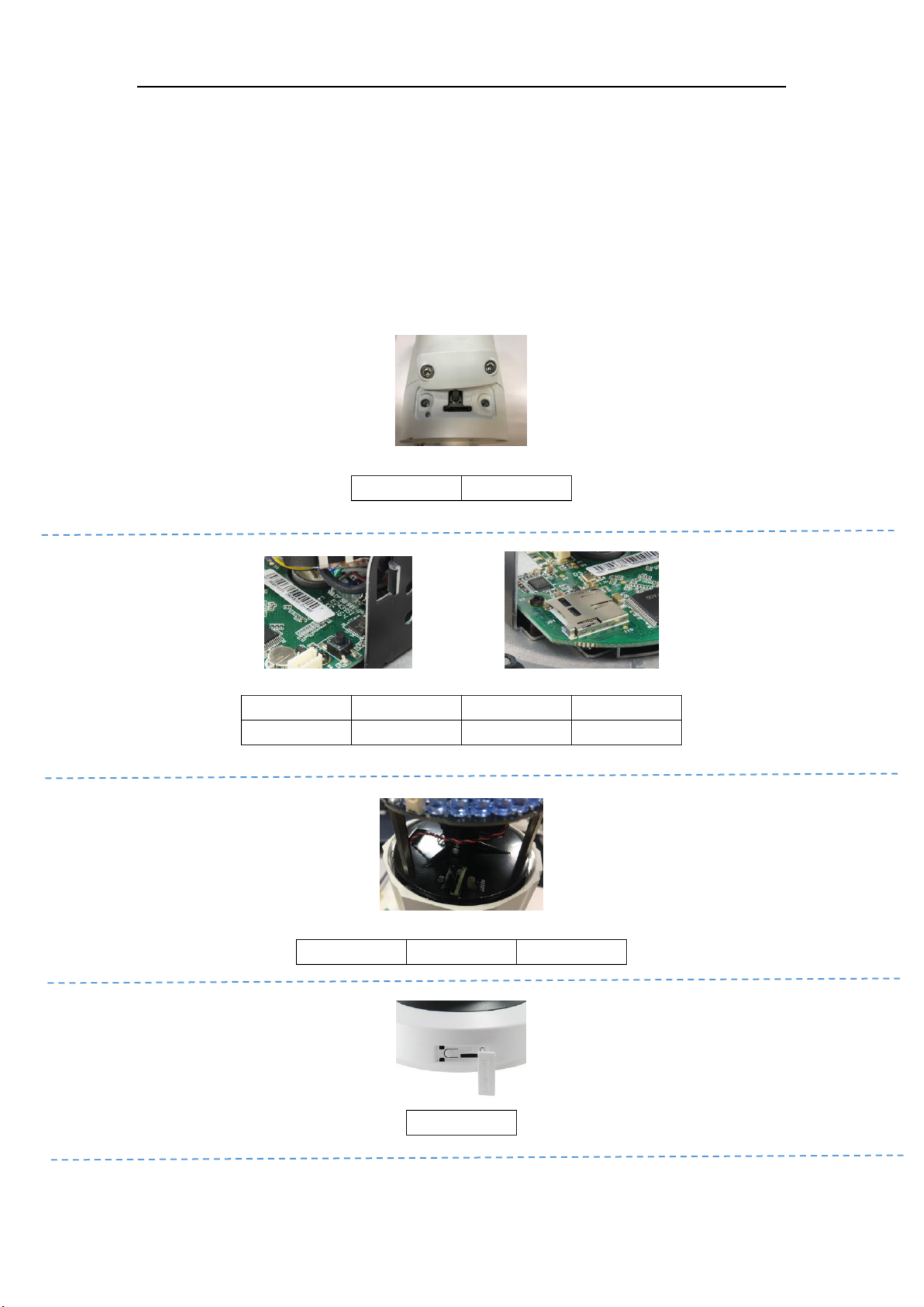
⚫ MicroSD Card Slot & RESET Button
MicroSD Card Slot & RESET Button
MicroSD Card Slot & RESET Button
MicroSD Card Slot & RESET Button MicroSD Card Slot & RESET Button
Unscrew the microSD/RESET/ Cover, and you can see the RESET button and the microSD card slot.
Press RESET about 10s when the camera is powering on or rebooting to restore the default settings,
including the user name, password, IP address, port No., etc.
Reset Button & SD card Slot Position
Reset Button & SD card Slot Position
Reset Button & SD card Slot Position
Reset Button & SD card Slot Position Reset Button & SD card Slot Position
F -5058 CS
F -5067 CS
F -3084 CS
F -3073 CS
F -3085 CS
FCS-3086
F -3090 CS
F -3096 CS
F -3087 CS
F -5059 CS
F -5060 CS
F -5068 CS
F -4103 CS

User Manual of Network Camera
8
FCS-3097
F -3098 CS
F -4203 CS
FCS-5092
F -5093 CS
FCS-5094
F -5095 CS
F -5096 CS

User Manual of Network Camera
9
Table of Contents
Chapter 1 System Requirement ................................................................................ 12
Chapter 2 Network Connection ............................................................................... 13
2.1 Setting the Network Camera over the LAN....................................................... 13
2.1.1 Wiring over the LAN ...................................................................................................... 13
2.1.2 Creating a Password ....................................................................................................... 14
2.2 Setting the Network Camera over the WAN ...................................................... 18
2.2.1 Static IP Connection ....................................................................................................... 18
2.2.2 Dynamic IP Connection .................................................................................................. 19
Chapter 3 Access to the Network Camera ............................................................... 22
3.1 Accessing by Web Browsers ................................................................................ 22
Chapter 4 -Fi Settings .......................................................................................... 25 Wi
4.1 Conguring Wi-Fi Connection in Manage and Ad-hoc Modes ....................... 25
4.2 Easy Wi-Fi Connection with WPS function ....................................................... 30
4.3 IP Property Settings for Wireless Network Connection ................................... 32
Chapter 5 Live View ................................................................................................. 34
5.1 Live View Page ..................................................................................................... 34
5.2 Starting Live View ................................................................................................ 35
5.3 Recording and Capturing Pictures Manually ................................................... 36
5.4 Operating PTZ Control ....................................................................................... 36
5.4.1 PTZ Control Panel .......................................................................................................... 36
5.4.2 Setting / Calling a Preset . ................................................................................................ 37
5.4.3 Setting / Calling a Patrol ................................................................................................. 39
Chapter 6 Network Camera Conguration ............................................................. 40
6.1 Conguring Local Parameters............................................................................ 40
6.2 Conguring Time Settings .................................................................................. 42
6.3 Conguring Network Settings ............................................................................ 44
6.3.1 Conguring TCP/IP Settings .......................................................................................... 44
6.3.2 Conguring Port Settings ............................................................................................... 45
6.3.3 Conguring PPPoE Settings ........................................................................................... 46
6.3.4 Conguring DDNS Settings ........................................................................................... 47
6.3.5 Conguring SNMP Settings ........................................................................................... 49
6.3.6 Conguring 802.1X Settings .......................................................................................... 51
6.3.7 Conguring QoS Settings ............................................................................................... 52
6.3.8 ngs Configuring UPnP™ Setti ......................................................................................... 53
6.3.9 Conguring Wireless Dial Settings ................................................................................ 53

User Manual of Network Camera
11
7.1 Conguring NAS Settings ................................................................................. 129
7.2 Conguring Recording Schedule ...................................................................... 131
7.3 Conguring Snapshot Settings ......................................................................... 135
7.4 Conguring Lite Storage ................................................................................... 137
7.5 Conguring Cloud Storage ............................................................................... 138
Chapter 8 Road Trac ........................................................................................... 140
Chapter 9 Playback ................................................................................................ 144
Chapter 10 Log Searching ................................................................................... 146
Chapter 11 Others ................................................................................................ 148
11.1 Managing User Accounts ................................................................................... 148
11.2 Authentication .................................................................................................... 150
11.3 Anonymous Visit ................................................................................................ 151
11.4 IP Address Filter ................................................................................................. 152
11.5 Security Service .................................................................................................. 153
11.6 Viewing Device Information .............................................................................. 154
11.7 Maintenance ....................................................................................................... 155
11.7.1 Rebooting the Camera .................................................................................................. 155
11.7.2 Restoring Default Settings ............................................................................................ 155
11.7.3 Exporting / Importing Conguration File ..................................................................... 156
11.7.4 Upgrading the System ...................................................................................................157
11.8 -232 Settings ................................................................................................... 157 RS
11.9 -485 Settings ................................................................................................... 158 RS
11.10 Service Settings ................................................................................................... 159
Appendix .................................................................................................................... 160
Appendix 1 SADP Software Introduction ..................................................................... 160
Appendix 2 Port Mapping .............................................................................................. 163

User Manual of Network Camera
13
Chapter 2 Network Connection
Note:
⚫ You shall acknowledge that the use of the product with Internet access might be
under network security risks. For avoidance of any network attacks and
information leakage, please strengthen your own protection. If the product does
not work properly, please contact with your dealer or the nearest service center.
⚫ To ensure the network security of the network camera, we recommend you to
have the network camera assessed and maintained termly. You can contact us if
you need such service.
Before you start:
⚫ If you want to set the network camera via LAN (Local Area Network), please a
refer to Section 2.1 Setting the Network Camera over the LAN.
⚫ If you want to set the network camera via WAN (Wide Area Network), please a
refer to Section 2.2 Setting the Network Camera over the WAN.
2.1 Setting the Network Camera over the LAN
Purpose:
To view and configure the camera via LAN, you need to connect the network a
camera in the same subnet with your computer, and install the SADP or iVMS-4200
software to search and change the IP of the network camera.
Note: For the detailed introduction of SADP, please refer to Appendix 1.
2.1.1 Wiring over the LAN
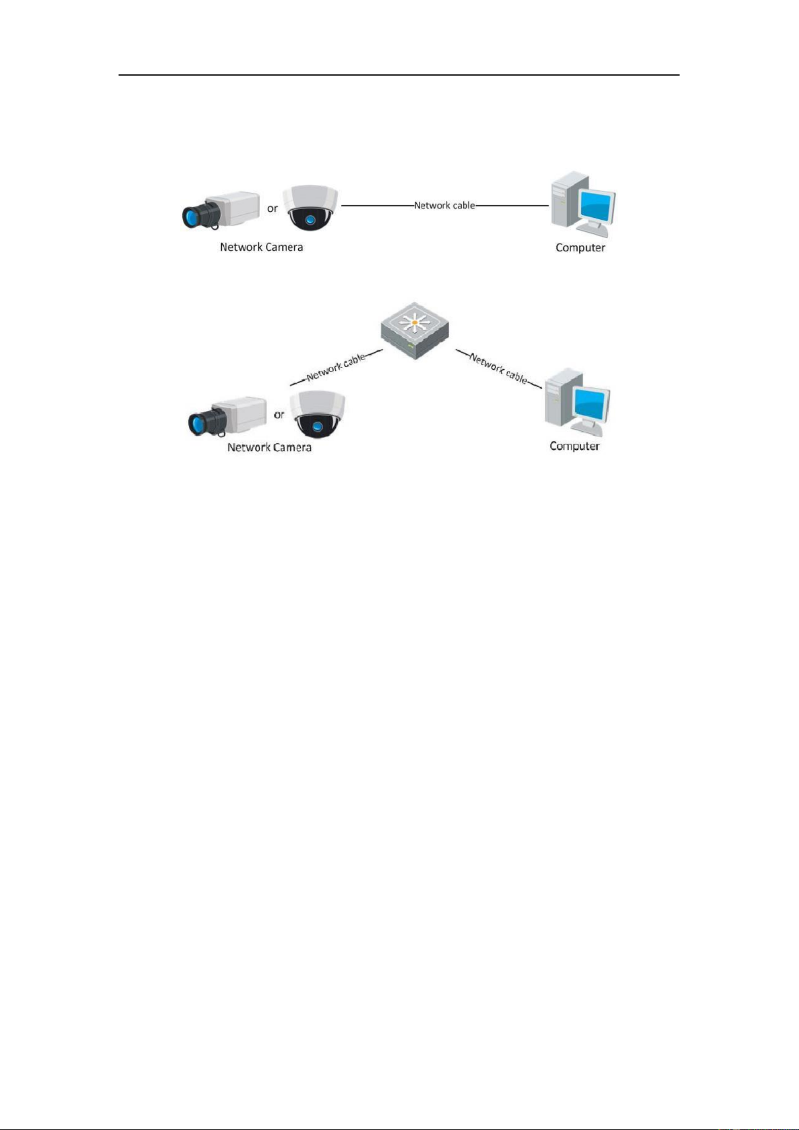
The following figures show the two ways of cable connection of network camera a
and computer: a
Purpose:
⚫ To test the network camera, you can directly connect the network camera to the
computer with a network cable as shown in Figure 2-1.
User Manual of Network Camera
14
⚫ Refer to the Figure 2-2 to set network camera over the LAN via a switch or a
router.
Figure 2-1 Connecting Directly
Figure 2-2 Connecting via a Switch or Router a
2.1.2 Creating a Password
You are required to activate the camera first by setting a strong password for it before
you can use the camera.
Creating a Password via Web Browser, Creating a Password via SADP, and Creating a
Password via Client Software are all supported.
❖ Creating a Password via Web Browser
Steps:
1. Power on the camera, and connect the camera to the network.
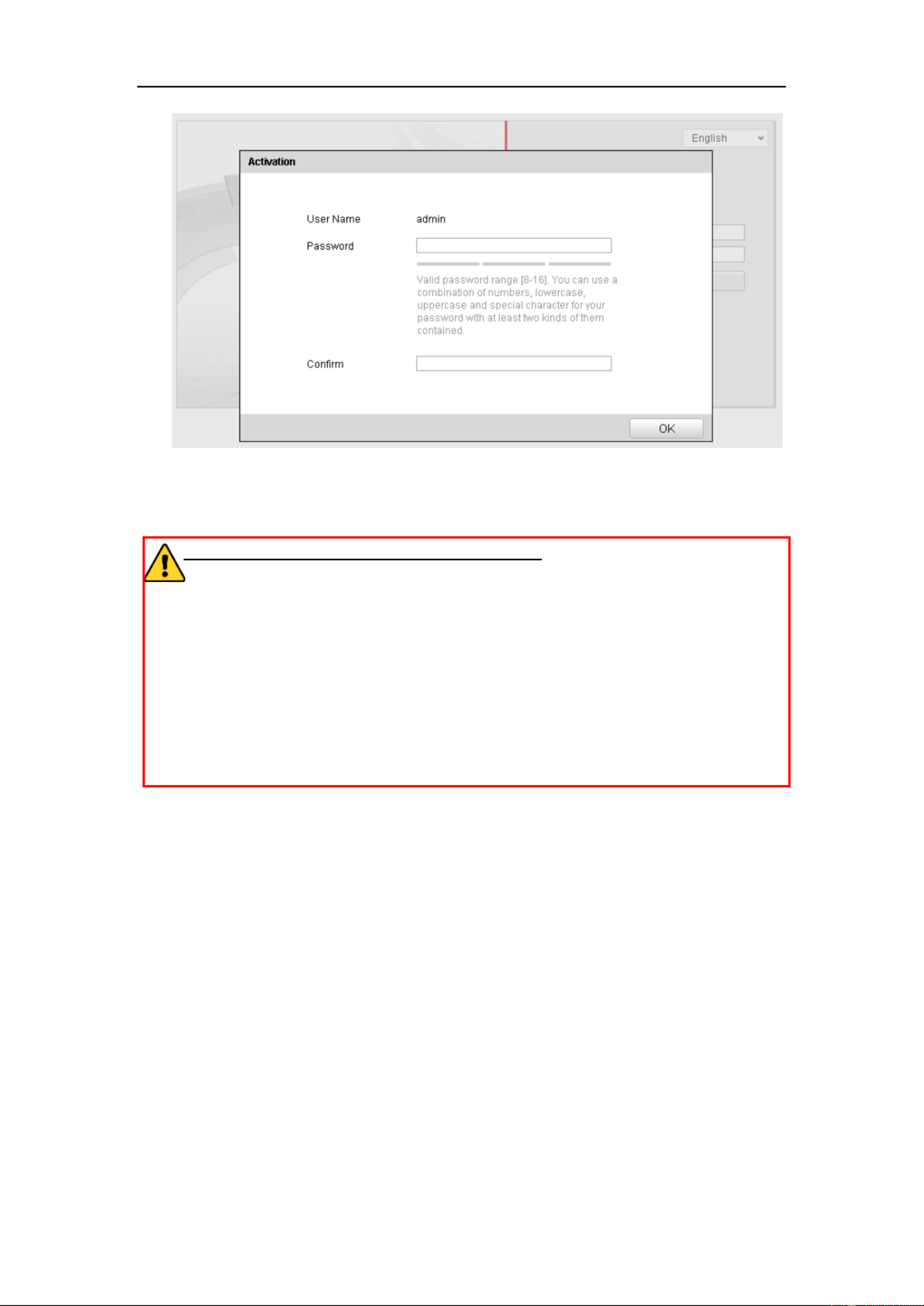
2. Input the IP address into the address bar of the web browser, and click Enter to
enter the activation interface.
Notes:
⚫ The default IP address of the camera is 192.168.1.64.
⚫ For the camera enables the DHCP by default, the IP address is allocated
automatically. And you need to activate the camera via SADP software. Please refer to
the following chapter for Activation via SADP.
User Manual of Network Camera
15
Figure 2-3 Creating a Password via Web Browser
3. Create a password and input the password into the password field.
STRONG PASSWORD RECOMMENDED– We highly recommend you
create a strong password of your own choosing (using a minimum of 8
characters, including at least three of the following categories: upper case letters,
lower case letters, numbers, and special characters) in order to increase the
security of your product. And we recommend you reset your password regularly,
especially in the high security system, resetting the password monthly or weekly
can better protect your product.
4. Confirm the password.
5. Click OK to save the password and enter the live view interface.
❖ Creating a Password via SADP Software
SADP software is used for detecting the online device, activating the camera, and
resetting the password.
Get the SADP software from the supplied disk or the official website, and install the
SADP according to the prompts. Follow the steps to activate the camera.
Steps:
1. Run the SADP software to search the online devices.
2. Check the device status from the device list, and select the inactive device.

User Manual of Network Camera
16
Figure 2-4 SADP Interface
3. Create a password and input the password in the password field, and confirm the
password.
STRONG PASSWORD RECOMMENDED– We highly recommend
you create a strong password of your own choosing (using a minimum
of 8 characters, including at least three of the following categories:
upper case letters, lower case letters, numbers, and special characters) in
order to increase the security of your product. And we recommend you
reset your password regularly, especially in the high security system,
resetting the password monthly or weekly can better protect your
product.
4. Click to save the password. OK
You can check whether the activation is completed on the popup window. If activation
failed, please make sure that the password meets the requirement and try again.
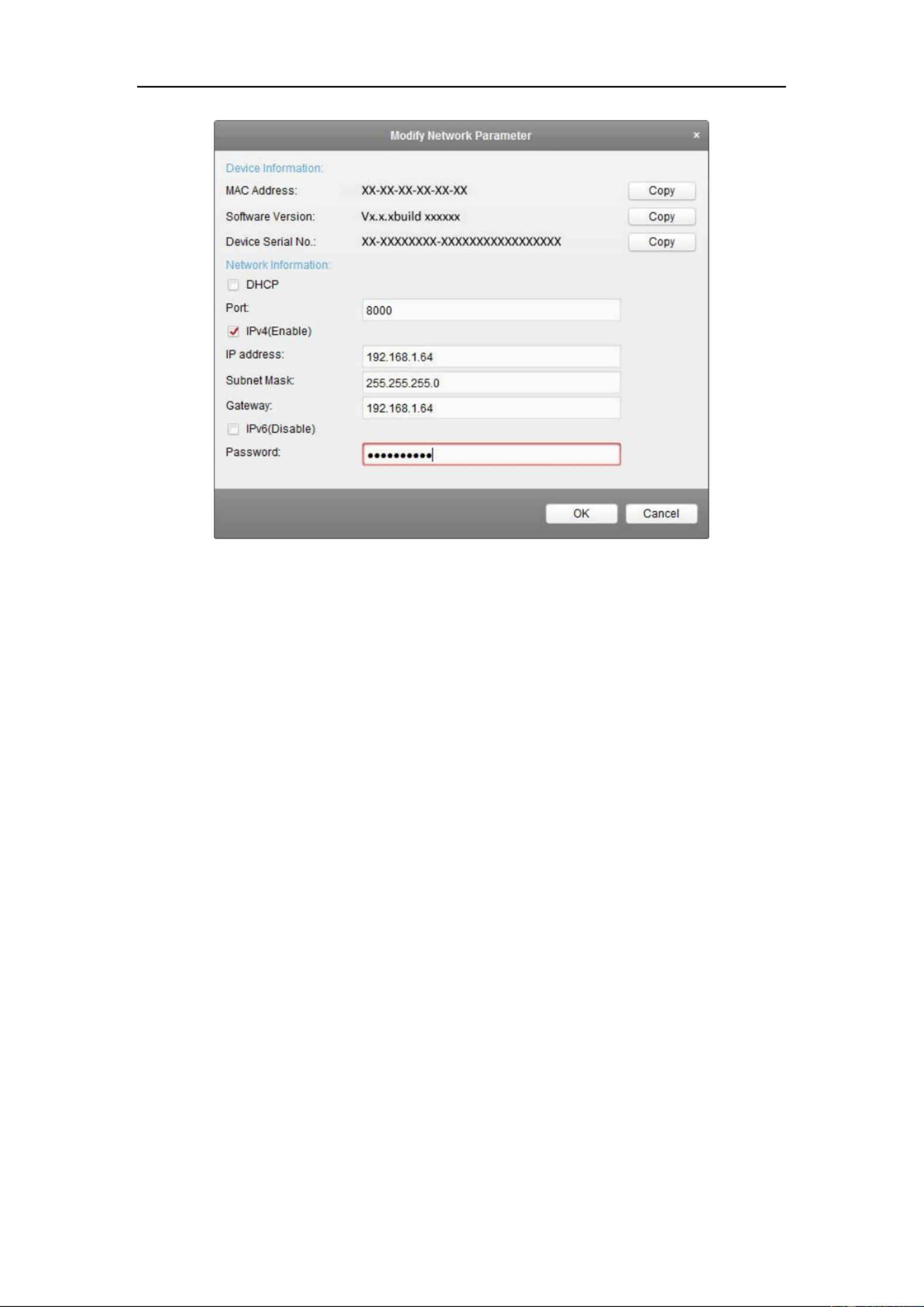
5. Change the device IP address to the same subnet with your computer by eithe r
modifying the IP address manually or checking the checkbox of Enable DHCP.
User Manual of Network Camera
18
Figure 2-7 Modifying the Network Parameters
3. Change the device IP address to the same subnet with your computer by either
modifying the IP address manually or checking the checkbox of Enable DHCP.
4. Input the password to activate your IP address modification.
2.2 Setting the Network Camera over the WAN
Purpose:
This section explains how to connect the network camera to the WAN with a static IP
or a dynamic IP.
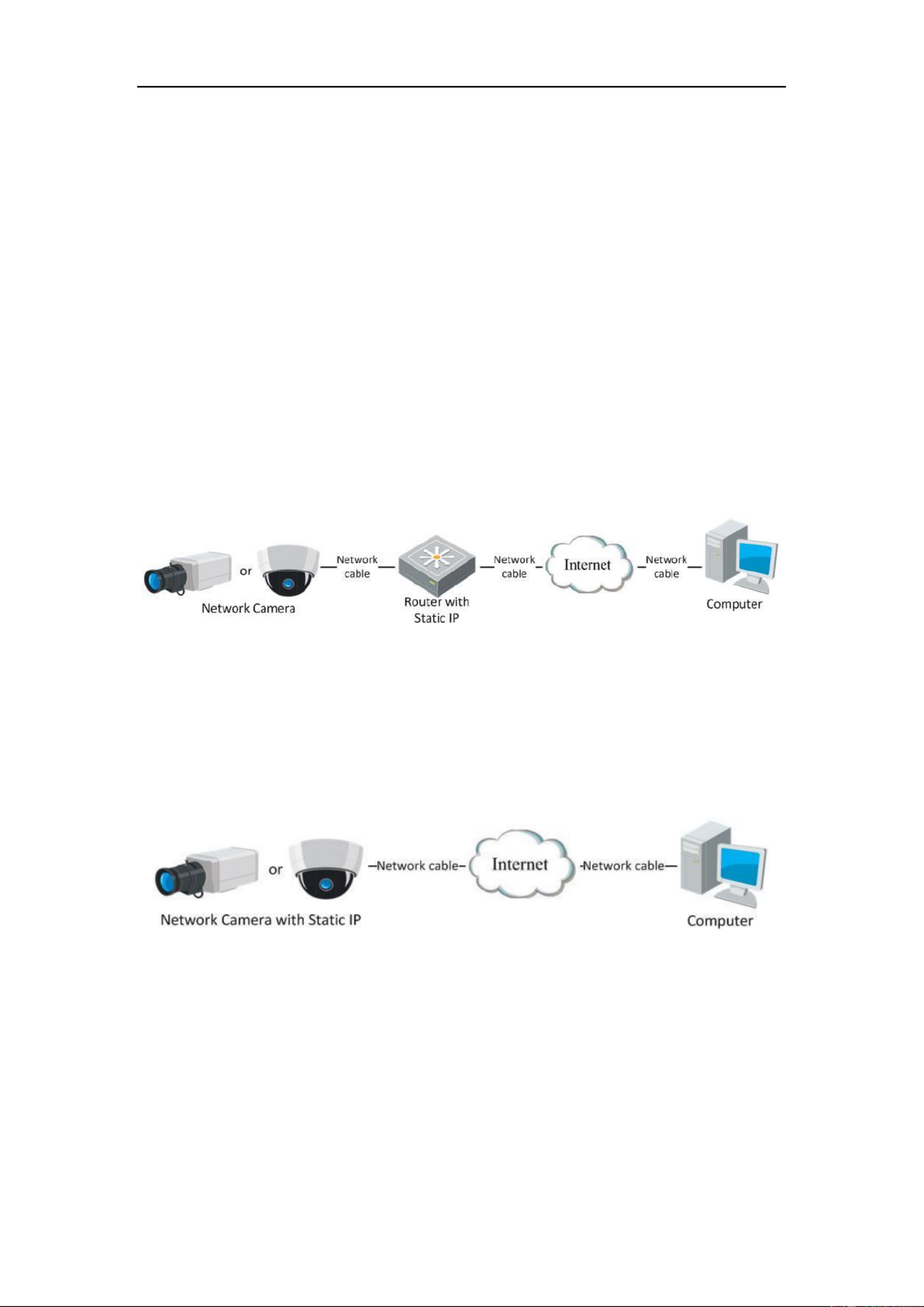
2.2.1 Static IP Connection
Before you start:
Please apply a static IP from an ISP (Internet Service Provider). With the static IP
address, you can connect the network camera via a router or connect it to the WAN
directly.
⚫ Connecting the network camera via a router
User Manual of Network Camera
19
Steps:
1. Connect the network camera to the router.
2. Assign a LAN IP address, the subnet mask and the gateway. Refer to Section 2.1.2
for detailed IP address configuration of the network camera.
3. Save the static IP in the router.
4. Set port mapping, e.g., 80, 8000, and 554 ports. The steps for port mapping vary
according to the different routers. Please call the router manufacturer for
assistance with port mapping.
Note: Refer to Appendix 2 for detailed information about port mapping.
5. Visit the network camera through a web browser or the client software over the
internet.
Figure 2-8 Accessing the Camera through Router with Static IP
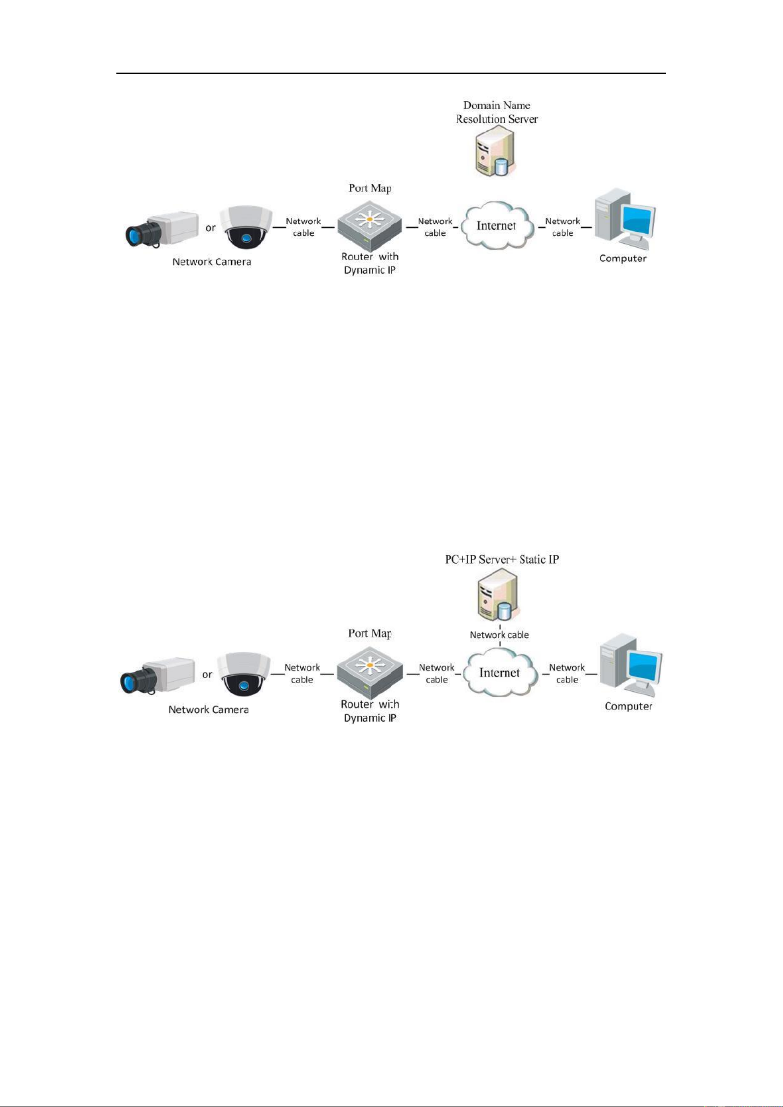
⚫ Connecting the network camera with static IP directly
You can also save the static IP in the camera and directly connect it to the internet
without using a router. Refer to Section 2.1.2 for detailed IP address configuration of
the network camera.
Figure 2-9 Accessing the Camera with Static IP Directly
2.2.2 Dynamic IP Connection
Before you start:
Please apply a dynamic IP from an ISP. With the dynamic IP address, you can connect
the network camera a modem or a router. to
User Manual of Network Camera
21
Figure 2-11 Normal Domain Name Resolution
Steps:
1. Apply a domain name from a domain name provider.
2. Configure the DDNS settings in the interface of the network DDNS Settings
camera. Refer to for detailed Section 6.3.4 Configuring DDNS Settings
configuration.
3. Visit the camera via the applied domain name.
⧫ Private Domain Name Resolution
Figure 2-12 Private Domain Name Resolution
Steps:
1. Install and run the IP Server software in a computer with a static IP.
2. Access the network camera through the LAN with web browser or the client a
software.
3. Enable DDNS and select IP Server as the protocol type. Refer to Section 6.3.4
Configuring DDNS Settings for detailed configuration.
User Manual of Network Camera
22
Chapter 3 Access to the Network
Camera
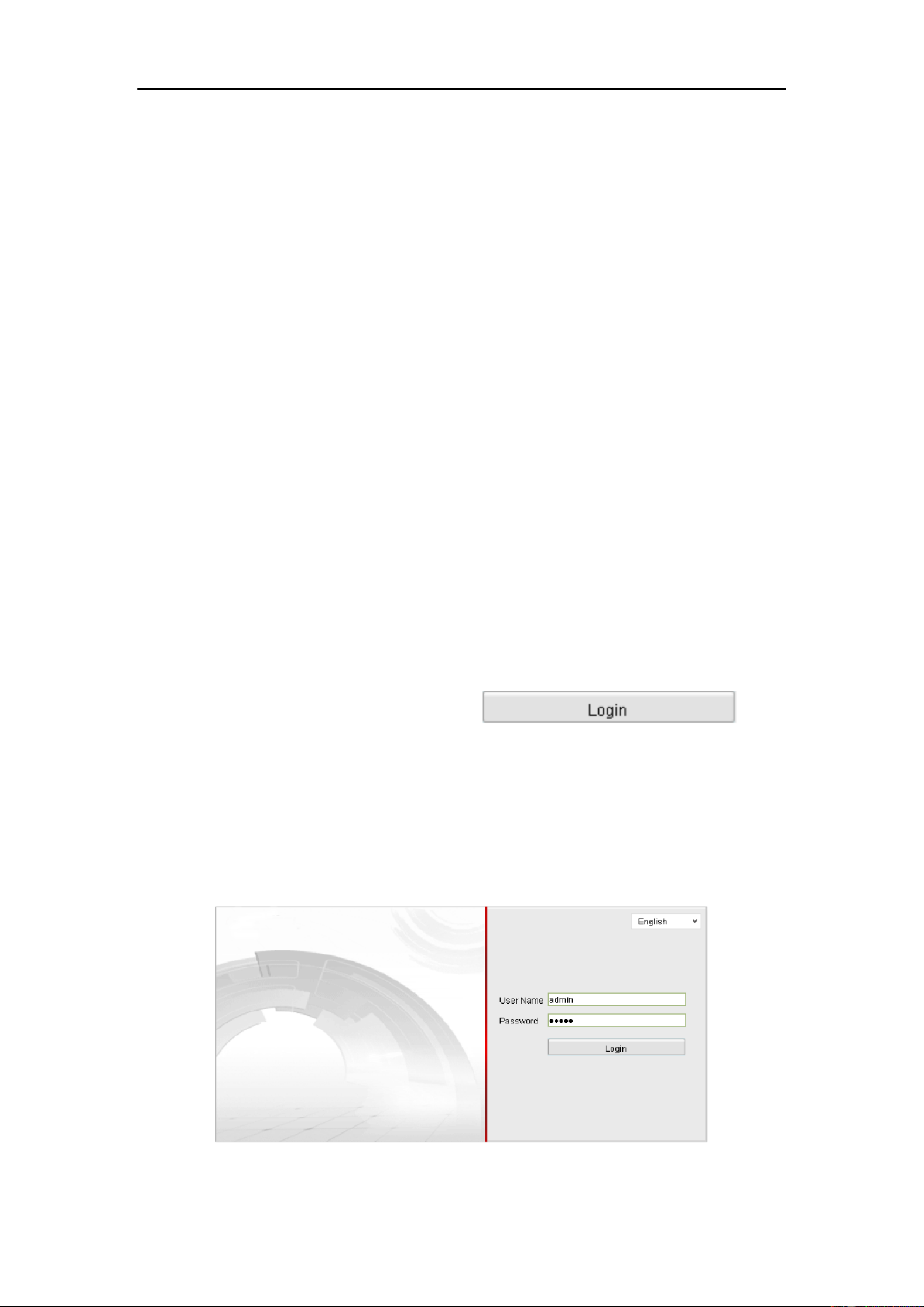
3.1 Accessing by b Browsers We
Steps:
1. Open the web browser.
2. In the browser address bar, input the IP address of the network camera, and press
the key to enter the login interface. Enter
3. Activate the network camera for the first time using, refer to the section 2.1.2 for
details..
Note:
⚫ The default IP address is 192.168.1.64.
⚫ If the camera is not activated, please activate the camera first according to
Chapter 3.1 or Chapter 3.2.
4. Select English as the interface language on the top-right of login interface.
5. Input the user name and password and click .
The admin user should configure the device accounts and user/operator permissions
properly. Delete the unnecessary accounts and user/operator permissions.
Note:
The IP address gets locked if the admin user performs 7 failed password attempts
(5 attempts for the user/operator).
Figure 3-1 Login Interface
User Manual of Network Camera
23
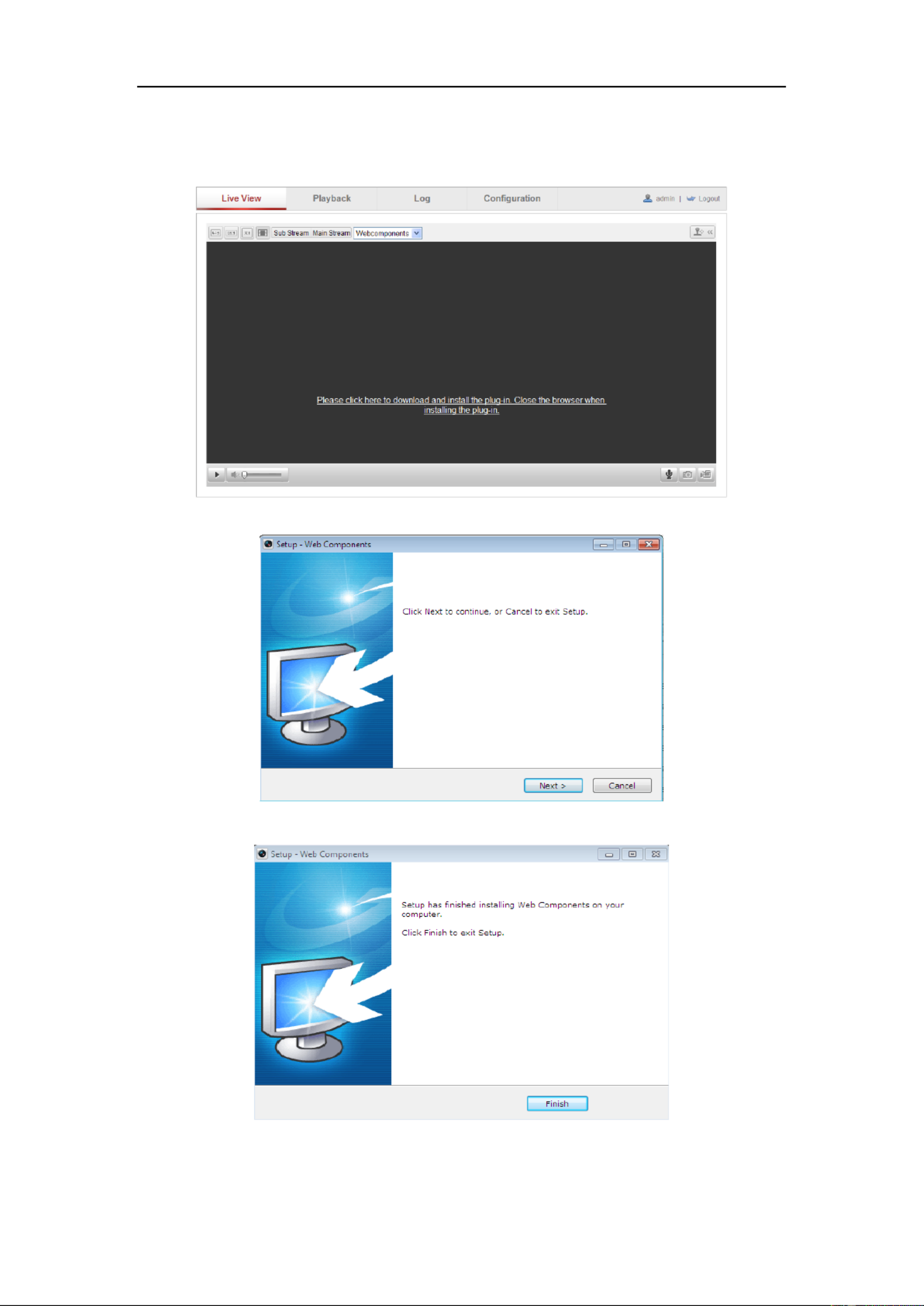
6. Install the plug-in before viewing the live video and operating the camera. Please
follow the installation prompts to install the plug- . in
Figure 3-2 Download and Install Plug- in
Figure 3-3 Install Plug-in (1)
Figure 3-4 Install Plug-in (2)
Note: You may have to close the web browser to install the plug-in. Please reopen the

User Manual of Network Camera
24
web browser and log in again after installing the plug-in.

User Manual of Network Camera
26
4. Check the checkbox to select the and the Network mode as Manage, Security
mode of the network is automatically shown when you select the wireless
network, please don’t change it manually.
Note: These parameters are exactly identical with those of the router.
5. Enter the key to connect the wireless network. The key should be that of the
wireless network connection you set on the router.
Wireless Connection in Ad-hoc Mode
If you choose the Ad-hoc mode, you don’t need to connect the wireless camera via a
router. The scenario is the same as you connect the camera and the PC directly with a
network cable.
Steps:
1. Choose Ad-hoc mode.
Figure 4-3 -Fi Setting- Wi Ad-hoc
2. Customize a SSID for the camera.
3. Choose the Security Mode of the wireless connection.
Figure 4-4 Security Mode- Ad-hoc Mode
4. Enable the wireless connection function for your PC.
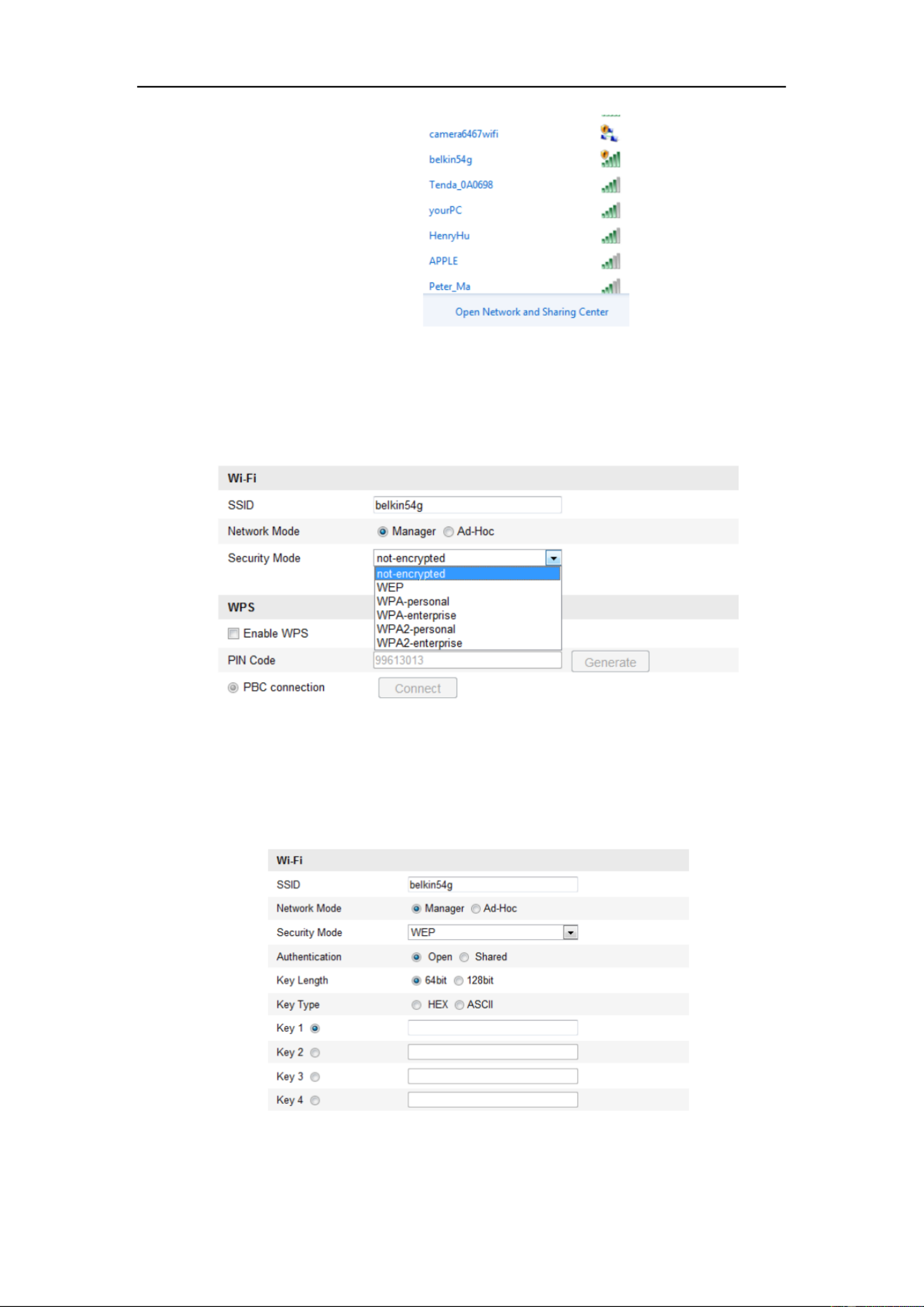
5. On the PC side, search the network and you can see the SSID of the camera
listed.
User Manual of Network Camera
27
Figure 4-5 -hoc Connection Point Ad
6. Choose the SSID and connect.
Security Mode Description:
Figure 4-6 Security Mode
You can choose the Security Mode as not-encrypted, WEP, WPA-personal,
WPA-enterprise, WPA2-personal, and WPA2-enterprise.
WEP mode:
Figure 4-7 WEP Mode
⚫ Authentication - Select Open or Shared Key System Authentication, depending on

User Manual of Network Camera
28
the method used by your access point. Not all access points have this option, in
which case they probably use Open System, which is sometimes known as SSID
Authentication.
⚫ Key length - This sets the length of the key used for the wireless encryption, 64 or
128 bit. The encryption key length can sometimes be shown as 40/64 and
104/128.
⚫ Key type - The key types available depend on the access point being used. The
following options are available:
HEX - Allows you to manually enter the hex key.
ASCII - In this method the string must be exactly 5 characters for 64-bit WEP
and 13 characters for 128-bit WEP.
WPA-personal and WPA2-personal Mode:
Enter the required Pre-shared Key for the access point, which can be a hexadecimal
number or a passphrase.
Figure 4-8 Security Mode- WPA-personal
WPA- enterprise and WPA2-enterprise Mode:
Choose the type of client/server authentication being used by the access point;
EAP-TLS or EAP-PEAP.
EAP-TLS

User Manual of Network Camera
30
upper case letters, lower case letters, numbers and special characters) in order to
increase the security of your product.
⚫ Proper configuration of all passwords and other security settings is the
responsibility of the installer and/or end-user.
4.2 Easy Wi-Fi Connection with WPS function
Purpose:
The setting of the wireless network connection is never easy. To avoid the complex
setting of the wireless connection you can enable the WPS function.
WPS (Wi-Fi Protected Setup) refers to the easy configuration of the encrypted
connection between the device and the wireless router. The WPS makes it easy to add
new devices to an existing network without entering long passphrases. There are two
modes of the WPS connection, the PBC mode and the PIN mode.
Note: If you enable the WPS function, you do not need to configure the parameters
such as the encryption type and you don’t need to know the key of the wireless
connection.
Steps:
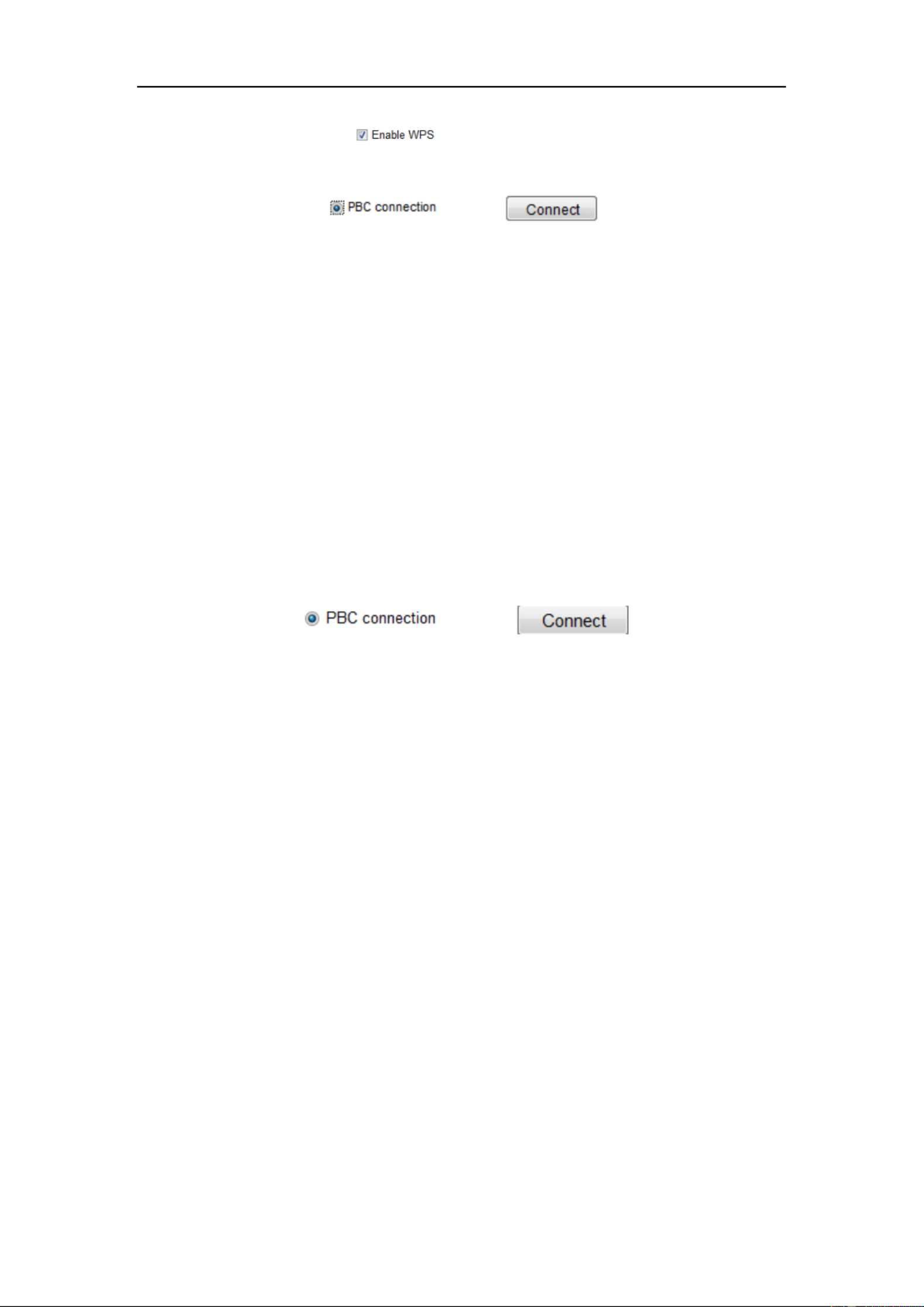
Figure 4-10 -Fi Settings - WPS Wi
PBC Mode:
PBC refers to the Push-Button-Configuration, in which the user simply has to push a
button, either an actual or virtual one (as the button on the configuration
interface of the IE browser), on both the Access Point (and a registrar of the network)
and the new wireless client device.
User Manual of Network Camera
31
1. Check the checkbox of to enable WPS.
2. Choose the connection mode as PBC.
Note: Support of this mode is mandatory for both the Access Points and the
connecting devices.
3. Check on the -Fi router to see if there is a WPS button. If yes push the button Wi
and you can see the indicator near the button start flashing, which means the WPS
function of the router is enabled. For detailed operation, please see the user guide of
the router.
4. Push the WPS button to enable the function on the camera.
If there is not a WPS button on the camera, you can also click the virtual button to
enable the PBC function on the web interface.
5. Click button. Connect
When the PBC mode is both enabled in the router and the camera, the camera and the
wireless network is connected automatically.
PIN Mode:
The PIN mode requires a Personal Identification Number (PIN) to be read from either
a sticker or the display on the new wireless device. This PIN must then be entered to
connect the network, usually the Access Point of the network.
Steps:
1. Choose a wireless connection on the list and the SSID is shown.

User Manual of Network Camera
33
1. Enter the TCP/IP configuration interface.
Configuration> Advanced Configuration> Network> TCP/IP
Or
Configuration> Basic Configuration> Network> TCP/IP
Figure 4-12 TCP/IP Settings
2. Select the NIC as wlan.
3. Customize the IPv4 address, the IPv4 Subnet Mask and the Default Gateway.
The setting procedure is the same with that of LAN.
If you want to be assigned the IP address you can check the checkbox to enable the
DHCP.

User Manual of Network Camera
34
Chapter 5 Live View
5.1 Live View Page
Purpose:
The live view page allows you to view the real-time video, capture images, realize
PTZ control, set/call presets and configure video parameters.
Log the network camera to enter the live view page, or you can click in Live View on
the menu bar of the main page to enter the live view page.
Descriptions of the live view page:
Figure 5-1 Live View Page
Camera Model:
It lists the camera model you are connecting to.
Online Help:
Click to get the online help, which will guide you through the basic operations for
each function.
Menu Bar:
Click each tab to enter Live View, Playback, Log and Configuration page
respectively.

User Manual of Network Camera
36
Click to select the third-party plug-in.
Manually capture the picture.
/
Manually start/stop recording.
/
Audio on and adjust volume /Mute.
/
Turn on/off microphone.
/
Turn on/off digital zoom function.
/
Turn on/off 3D positioning function.
Note: The third stream and 3D positioning require the support of camera.
5.3 Recording and Capturing Pictures Manually
In the live view interface, click on the toolbar to capture the live pictures or
click to record the live view. The saving paths of the captured pictures and clips
can be set on the page. To configure remote Configuration > Local Configuration
scheduled recording, please refer to . Section 7.2
Note: The captured image will be saved as JPEG file or BMP file your computer. in
5.4 Operating PTZ Control
Purpose:
In the live view interface, you use the PTZ control buttons to realize pan/tilt/zoom can
control of the camera.
Note: To realize PTZ control, the camera connected to the network must support the
PTZ function or a pan/tilt unit has been installed to the camera. Please properly set the
PTZ parameters on RS-485 settings page referring to Section 12.9 .RS-485 Settings
5.4.1 PTZ Control Panel
On the live view page, click to show the PTZ control panel click to or
hide . it
Click the direction buttons to control the pan/tilt movements.

User Manual of Network Camera
38
Figure 5-4 Setting a Preset
2. Use the PTZ control buttons to move the lens the desired position. to
• Pan the camera to the right or left.
• Tilt the camera up or down.
• Zoom in or out.
• Refocus the lens.
3. Click to finish the setting of the current preset.
4. You can click to delete the preset.
Note: Up to 16 presets can be configured for the Network Mini PT Camera.
⚫ Calling a Preset:
This feature enables the camera to point to a specified preset scene manually or when
an event takes place.
For the defined preset, you can call it at any time to the desired preset scene.
In the PTZ control panel, select a defined preset from the list and click to call the
preset.
Or you can place the mouse on the presets interface, and call the preset by typing the
preset No. to call the corresponding presets.
Figure 5-5 Calling a Preset

User Manual of Network Camera
40
Chapter 6 Network Camera
Configuration
6.1 Configuring Local Parameters
Note: The local configuration refers to the parameters of the live view, record files
and captured pictures. The record files and captured pictures are the ones you record
and captured using the web browser and thus the saving paths of them are on the PC
running the browser.
Steps:
1. Enter the Local Configuration interface:
Configuration > Local Configuration
Figure 6-1 Local Configuration
Interface
2. Configure the following settings:
⚫ Live View Parameters: Set the protocol type and live view performance.
⧫ Protocol Type: TCP, UDP, MULTICAST and HTTP are selectable.
TCP: Ensures complete delivery of streaming data and better video quality,

User Manual of Network Camera
41
yet the real-time transmission will be affected.
UDP: Provides real-time audio and video streams.
HTTP: Allows the same quality as of TCP without setting specific ports for
streaming under some network environments.
MULTICAST: It’s recommended to select MCAST type when using the
Multicast function. For detailed information about Multicast, refer to Section
6.3.1 Configuring TCP/IP Settings.
⧫ Live View Performance: Set the live view performance to Shortest Delay or
Auto.
⧫ Rules: It refers to the rules on your local browser, select enable or disable to
display or not display the colored marks when the motion detection, face
detection, or intrusion detection is triggered. E.g.: enabled as the rules are, and
the face detection is enabled as well, when a face is detected, it will be marked
with a green rectangle on the live view.
⧫ Image Format: Choose the image format for picture capture.
⚫ Record File Settings: Set the saving path of the recorded video files. Valid for the
record files you recorded with the web browser.
⧫ Record File Size: Select the packed size of the manually recorded and
downloaded video files to 256M, 512M or 1G. After the selection, the
maximum record file size is the value you selected.
⧫ Save record files to: Set the saving path for the manually recorded video files.
⧫ Save downloaded files to: Set the saving path for the downloaded video files
in playback mode.
⚫ Picture and Clip Settings: Set the saving paths of the captured pictures and
clipped video files. Valid for the pictures you captured with the web browser.
⧫ Save snapshots in live view to: Set the saving path of the manually captured
pictures in live view mode.
⧫ Save snapshots when playback to: Set the saving path of the captured
pictures in playback mode.
⧫ Save clips to: Set the saving path of the clipped video files in playback mode.

User Manual of Network Camera
42
Note: You can click to change the directory for saving the clips and pictures. Browse
3. Click to save the settings. Save
6.2 Conguring Time Settings
Purpose:
You can follow the instructions in this section to congure the time synchronization
and DST settings.
Steps:
1. Enter the Time Settings interface:
Conguration > Basic Conguration > System > Time Settings
Or Conguration > Advanced Conguration > System > Time Settings
Figure 6-2 Time Settings
⚫ Select the Time Zone.
Select the Time Zone of your location from the drop-down menu.
⧫ Synchronizing Time by NTP Server.
(1) Check the checkbox to enable the function. NTP
(2) Congure the following settings:
Server Address: IP address of NTP server.
NTP Port: Port of NTP server.
Interval: The time interval between the two synchronizing actions with NTP
User Manual of Network Camera
44
6.3 Conguring Network Settings
6.3.1 Conguring TCP/IP Settings
Purpose:
TCP/IP settings must be properly congured before you operate the camera over
network. The camera supports both the IPv4 and IPv6. Both versions may be
congured simultaneously without conicting to each other, and at least one IP
version should be congured.
Steps:
1. Enter TCP/IP Settings interface:
Conguration > Basic Conguration > Network > TCP/IP
Or Conguration > Advanced Conguration > Network > TCP/IP
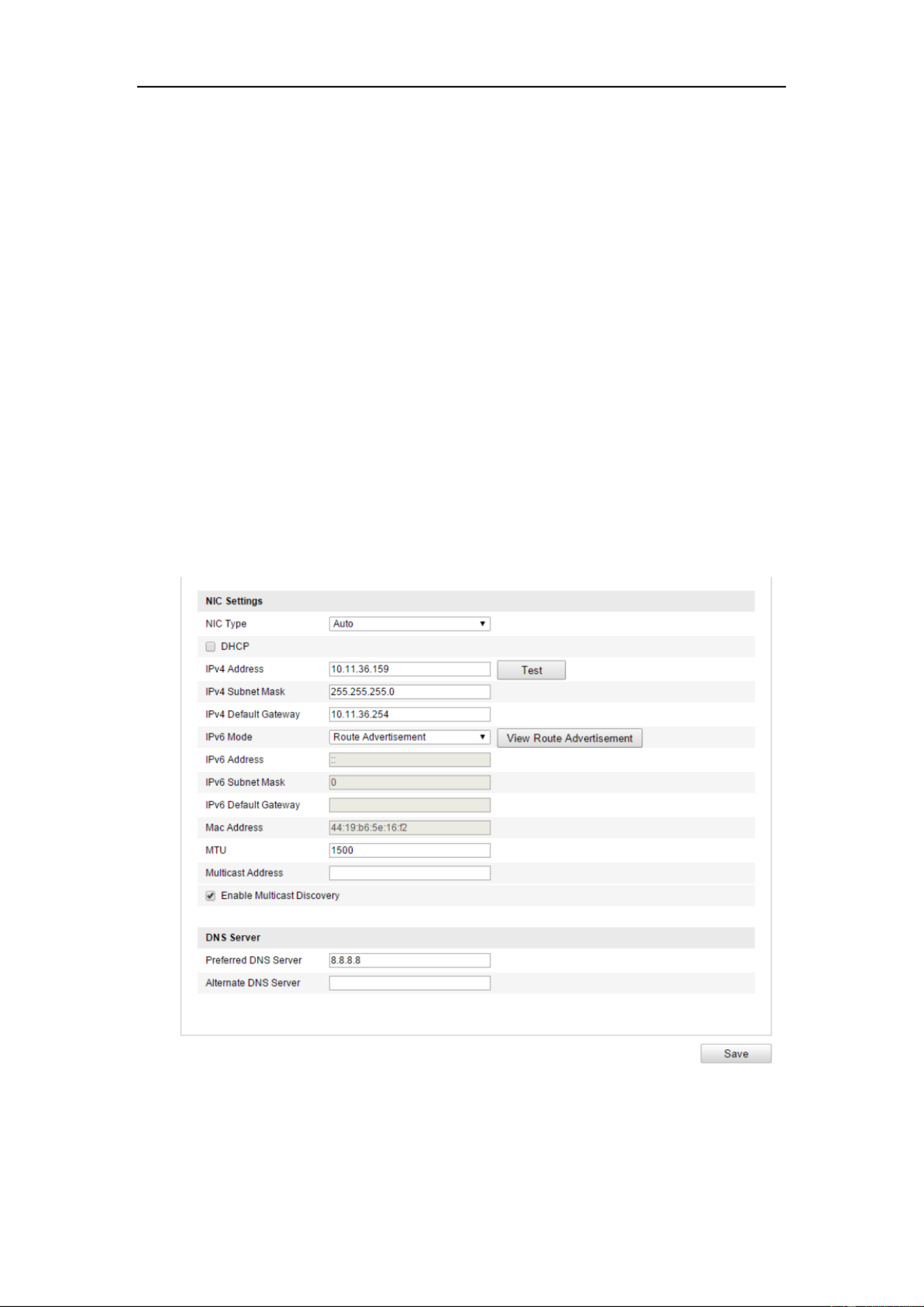
Figure 6-6 TCP/IP Settings
2. Congure the basic network settings, including the NIC Type, IPv4 or IPv6
Address, IPv4 or IPv6 Subnet Mask, IPv4 or IPv6 Default Gateway, MTU settings

User Manual of Network Camera
45
and Multicast Address.
3. (Optional) Check the checkbox of , and then the Enable Multicast Discovery
online network camera can be automatically detected by client software via
private multicast protocol in the LAN.
4. Click to save the above settings Save .
Notes :
⚫ The valid value range of MTU is 1280 ~ 1500.
⚫ The Multicast sends a stream to the multicast group address and allows multiple
clients to acquire the stream at the same time by requesting a copy from the
multicast group address. Before utilizing this function, you have to enable the
Multicast function of your router.
⚫ A reboot is required for the settings to take eect.
6.3.2 Conguring Port Settings
Purpose:
You can set the port No. of the camera, e.g. HTTP port, RTSP port and HTTPS port.
Steps:
1. Enter the Port Settings interface:
Conguration > Basic Conguration > Network > Port
Or Conguration > Advanced Conguration > Network > Port
Figure 6-7 Port Settings
2. Set the HTTP port, RTSP port, HTTPS port and server port of the camera.
HTTP Port: The default port number is 80, and it can be changed to any port No.
which is not occupied.
RTSP Port: The default port number is 554 and it can be changed to any port No.

User Manual of Network Camera
46
ranges from 1024 to 65535.
HTTPS Port: The default port number is 443, and it can be changed to any port
No. which is not occupied.
Server Port: The default server port number is 8000, and it can be changed to
any port No. ranges from 2000 to 65535.
3. Click to save the settings. Save
Note: A reboot is required for the settings to take eect.
6.3.3 Conguring PPPoE Settings
Steps:
1. Enter the PPPoE Settings interface:
Conguration >Advanced Conguration > Network > PPPoE
Figure 6-8 PPPoE Settings
2. Check the checkbox to enable this feature. Enable PPPoE
3. Enter , , and password for PPPoE access. User Name Password Conrm
Note: The User Name and Password should be assigned by your ISP.
⚫ For your privacy and to better protect your system against security risks, we
strongly recommend the use of strong passwords for all functions and network
devices. The password should be something of your own choosing (using a
minimum of 8 characters, including at least three of the following categories:
upper case letters, lower case letters, numbers and special characters) in order to
increase the security of your product.
⚫ Proper conguration of all passwords and other security settings is the
responsibility of the installer and/or end-user.

User Manual of Network Camera
47
4. Click to save and exit the interface. Save
Note: A reboot is required for the settings to take eect.
6.3.4 Conguring DDNS Settings
Purpose:
If your camera is set to use PPPoE as its default network connection, you can use the
Dynamic DNS (DDNS) for network access.
Before you start:
Registration on the DDNS server is required before conguring the DDNS settings of
the camera.
⚫ For your privacy and to better protect your system against security risks, we
strongly recommend the use of strong passwords for all functions and network
devices. The password should be something of your own choosing (using a
minimum of 8 characters, including at least three of the following categories :
upper case letters, lower case letters, numbers and special characters) in order to
increase the security of your product.
⚫ Proper conguration of all passwords and other security settings is the
responsibility of the installer and/or end-user.
Steps:
1. Enter the DDNS Settings interface:
Conguration > Advanced Conguration > Network > DDNS
2. Check the checkbox to enable this feature. Enable DDNS
3. Select . Four DDNS types are selectable: IPServer, -IP, and DDNS Type NO
DynDNS.
⚫
⚫
⚫
⚫⚫ DynDNS:
Steps:
(1) Enter of DynDNS (e.g. members.dyndns.org). Server Address

User Manual of Network Camera
49
(1) Choose the DDNS Type as NO-IP.
Figure 6-11 -IP Settings NO
(2) Enter the Server Address as www.noip.com
(3) Enter the Domain name you registered.
(4) Enter the Port number, if needed.
(5) Enter the User Name and Password.
(6) Click and then you can view the camera with the domain name. Save
Note: A reboot is required for the settings to take effect.
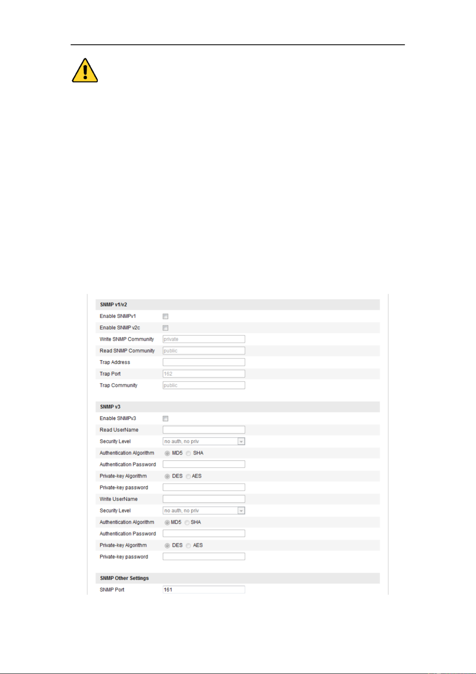
6.3.5 Conguring SNMP Settings
Purpose:
You can set the SNMP function to get camera status, parameters and alarm related
information and manage the camera remotely when it is connected to the network.
Before you start:
Before setting the SNMP, please download the SNMP software and manage to
receive the camera information via SNMP port. By setting the Trap Address, the
camera can send the alarm event and exception messages to the surveillance center.
Note: The SNMP version you select should be the same as that of the SNMP software.
And you also need to use the dierent version according to the security level you
required. SNMP v1 provides no security and SNMP v2 requires password for access.
And SNMP v3 provides encryption and if you use the third version, HTTPS protocol
must be enabled.
User Manual of Network Camera
50
⚫ For your privacy and to better protect your system against security risks, we
strongly recommend the use of strong passwords for all functions and network
devices. The password should be something of your own choosing (using a
minimum of 8 characters, including at least three of the following categories :
upper case letters, lower case letters, numbers and special characters) in order to
increase the security of your product.
⚫ Proper conguration of all passwords and other security settings is the
responsibility of the installer and/or end-user.
Steps:
1. Enter the SNMP Settings interface:
Conguration > Advanced Conguration > Network > SNMP
Figure 6-12 SNMP Settings
User Manual of Network Camera
52
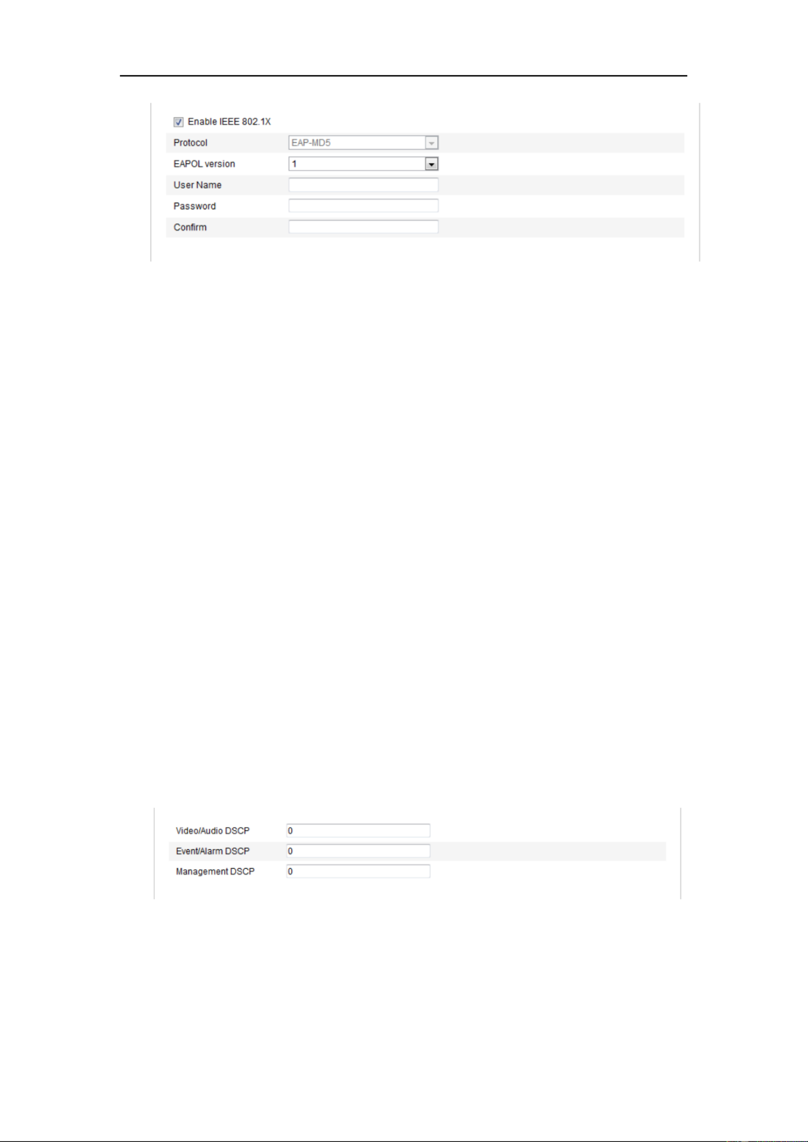
Figure 6-13 802.1X Settings
2. Check the checkbox to enable the feature. Enable IEEE 802.1X
3. Congure the 802.1X settings, including EAPOL version, user name and
password.
Note: The EAPOL version must be identical with that of the router or the switch.
4. Enter the user name and password to access the server.
5. Click to nish the settings. Save
Note: A reboot is required for the settings to take eect.
6.3.7 Conguring QoS Settings
Purpose:
QoS (Quality of Service) can help solve the network delay and network congestion by
conguring the priority of data sending.
Steps:
1. Enter the QoS Settings interface:
Conguration >Advanced Conguration > Network > QoS
Figure 6-14 QoS Settings
2. Congure the QoS settings, including video / audio DSCP, event / alarm DSCP
and Management DSCP.
The valid value range of the DSCP is 0-63. The bigger the DSCP value is, the
User Manual of Network Camera
53
higher the priority is.
Note: DSCP refers to the Dierentiated Service Code Point; and the DSCP value
is used in the IP header to indicate the priority of the data.
3. Click to save the settings. Save
Note: A reboot is required for the settings to take effect.
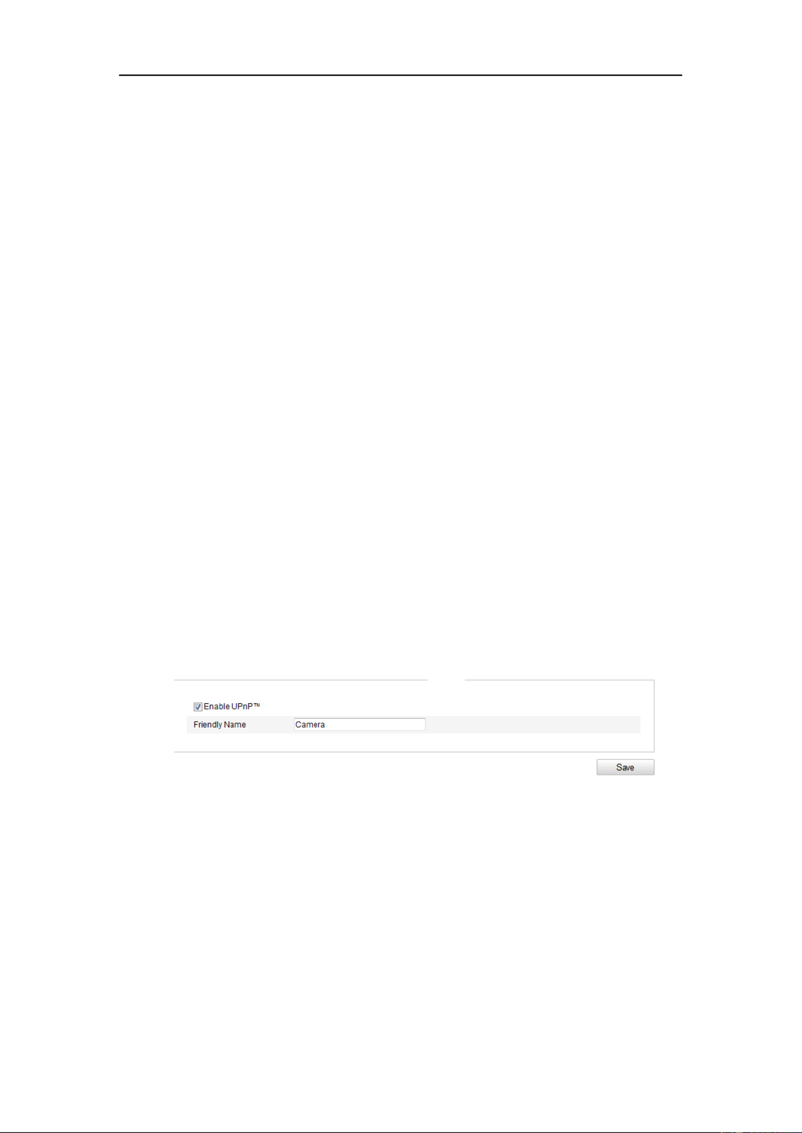
6.3.8 Conguri ng UPnP™ Settings
Universal Plug and Play (UPnP™) is a networking architecture that provides
compatibility among networking equipment, software and other hardware devices.
The UPnP protocol allows devices to connect seamlessly and to simplify the
implementation of networks in the home and corporate environments.
With the function enabled, you don’t need to configure the port mapping for each port,
and the camera is connected to the Wide Area Network via the router.
Steps:
1. Enter the UPnP™ settings interface.
Conguration >Advanced Conguration > Network > UPnP
2. Check the checkbox to enable the UPnP™ function.
The name of the device when detected online can be edited.
Figure 6-15 UPnP Settings
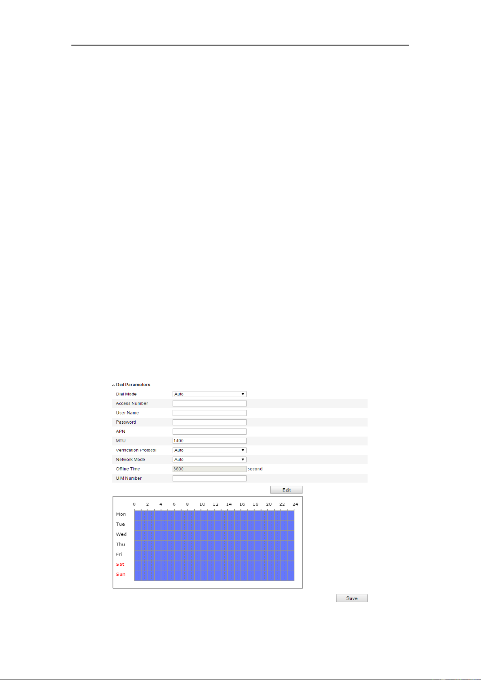
6.3.9 Conguring Wireless Dial Settings
Purpose:
Data stream of audio, video and image can be transferred via 3G / 4G wireless
network.
Note: The wireless dial function requires the support of the camera.
User Manual of Network Camera
54
1. Click the Wireless Dial tab to enter the Wireless Dial conguration interface.
2. Check the checkbox of to enable the wireless dial settings. Enable
3. Congure the dial parameters.
1) Select the dial mode from the drop-down list. Auto and Manual are selectable.
If Auto is selected, you can set the arming schedule for dialing; If Manual is
selected, you can set the oine time and manual dialing parameters.
2) Set the access number, user name, password, APN, MTU and verication
protocol. You can also leave these parameters blank, and the device will
adopt the default settings for dialing after other parameters are congured.
3) Select the network mode from the drop-down list. Auto, 3G and 4G are
selectable. If Auto is selected, the network selection priority comes as: 4G >
3G > Wired Network.
4) Input the oine time if Manual is selected as the dial mode.
5) Input the UIM Number (Mobile Phone Number).
6) Click the button to set the arming schedule if Auto is selected as the dial Edit
mode.
7) Click to save the settings. Save
Figure 6-16 Dial Parameters

User Manual of Network Camera
56
Figure 6-19 S Alarm Settings SM
3) Input the mobile phone number for the white list, check the checkbox of
Reboot via SMS, select the alarm for SMS push, and click OK.
Note: To reboot the device via SMS, send the message "reboot" to the device,
and the device will reply a message "reboot success" after rebooting
succeeded.
4) (Optional) You can click to send a message to the mobile Send Test SMS
phone for test.
5) Click to save the settings. Save
6.3.10 Email Sending Triggered by Alarm
Purpose:
The system can be congured to send an Email notication to all designated receivers
if an alarm event is detected, e.g., motion detection event, video loss, video tampering,
etc.
Before you start:
Please congure the DNS Server settings under Basic Conguration > Network >
TCP/IP Advanced Conguration > Network > TCP/IPor before using the Email
function.
Steps:
1. Enter the TCP/IP Settings (Conguration > Basic Conguration > Network >
TCP/IP Conguration > Advanced Conguration > Network > TCP/IP) or to
User Manual of Network Camera
57
set the IPv4 Address, IPv4 Subnet Mask, IPv4 Default Gateway and the Preferred
DNS Server.
Note: Please refer to for detailed Conguring TCP/IP SettingsSection 6.3.1
information.
2. Enter the Email Settings interface:
Conguration > Advanced Conguration > Network > Email
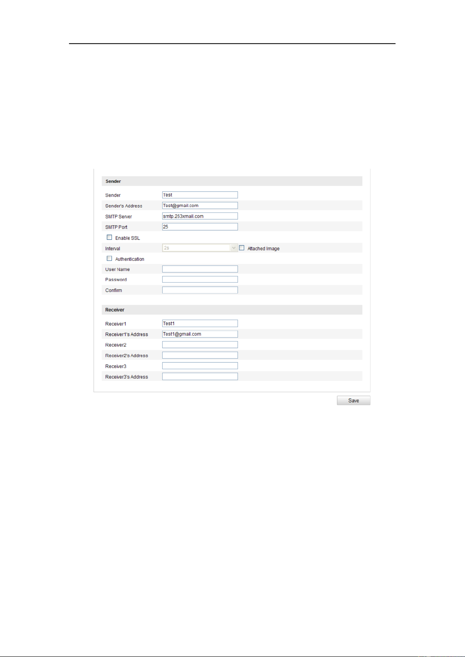
Figure 6-20 Email Settings
3. Congure the following settings:
Sender: The name of the email sender.
Sender’s Address: The email address of the sender.
SMTP Server: The SMTP Server IP address or host name (e.g.,
smtp.263xmail.com).
SMTP Port: The SMTP port. The default TCP/IP port for SMTP is 25 (not
secured). And the SSL SMTP port is 465.
Enable SSL: Check the checkbox to enable SSL if it is required by the SMTP
server.

User Manual of Network Camera
58
Attached Image: Check the checkbox of Attached Image if you want to send
emails with attached alarm images.
Interval: The interval refers to the time between two actions of sending attached
pictures.
Authentication (optional): If your email server requires authentication, check
this checkbox to use authentication to log in to this server and enter the login user
Name and password.
⚫ For your privacy and to better protect your system against security risks, we
strongly recommend the use of strong passwords for all functions and
network devices. The password should be something of your own choosing
(using a minimum of 8 characters, including at least three of the following
categories: upper case letters, lower case letters, numbers and special
characters) in order to increase the security of your product.
⚫ Proper conguration of all passwords and other security settings is the
responsibility of the installer and/or end-user.
Choose Receiver: Select the receiver to which the email is sent. Up to 2 receivers
can be congured.
Receiver: The name of the user to be notied.
Receiver’s Address: The email address of user to be notied.
4. Click to save the settings. Save
6.3.11 Conguring NAT (Network Address Translation) Settings
Purpose:
1. Enter the NAT settings interface.
Conguration >Advanced Conguration > Network > NAT
2. Choose the port mapping mode.
To port mapping with the default port numbers:
Choose Port Mapping Mode as Auto .

User Manual of Network Camera
60
login the FTP server.
⚫ For your privacy and to better protect your system against security risks, we
strongly recommend the use of strong passwords for all functions and
network devices. The password should be something of your own choosing
(using a minimum of 8 characters, including at least three of the following
categories: upper case letters, lower case letters, numbers and special
characters) in order to increase the security of your product.
⚫ Proper conguration of all passwords and other security settings is the
responsibility of the installer and/or end-user.
Directory Directory Structure: In the eld, you can select the root directory,
parent directory and child directory. When the parent directory is selected, you
have the option to use the Device Name, Device Number or Device IP for the
name of the directory; and when the Child Directory is selected, you can use the
Camera Name or Camera No. as the name of the directory.
Upload type: To enable uploading the captured picture to the FTP server.
Anonymous Access to the FTP Server (in which case the user name and
p required.) Anonymousassword won’t be : Check the checkbox to enable the
anonymous access to the FTP server.
Note: The anonymous access function must be supported by the FTP server.
3. Click to save the settings. Save
Note: If you want to upload the captured pictures to FTP server, you have to
enable the timing snapshot or event-triggered snapshot on page. For Snapshot
detailed information, please refer to the Section 7.3.
6.3.13 Platform Access
Platform access provides you an option to manage the devices via EZVIZ Cloud P2P
platform.
Note: Platform access function varies according to the camera model and it requires

User Manual of Network Camera
63
⚫
⚫
⚫
⚫⚫ Create the authorized certicate
1) Click Create button to create the certicate request.
2) Download the certicate request and submit it to the trusted certicate
authority for signature.
3) After receiving the signed valid certicate, import the certicate to the device.
4. There will be the certicate information after you successfully create and install
the certicate.
Figure 6-26 stalled Certicate In
5. Click the button to save the settings. Save
6.4 Conguring Video and Audio Settings
6.4.1 Conguring Video Settings
Steps:
1. Enter the Video Settings interface:
Conguration >Basic Conguration > Video / Audio > Video
Or Conguration > Advanced Conguration > Video / Audio > Video

User Manual of Network Camera
66
Scalable Video Coding is an extension of the H.264/AVC standard. Select OFF /
ON to disable / enable the SVC function. Select Auto, and the device will
automatically extract frames from the original video when the network bandwidth
is insucient.
Smoothing:
It refers to the smoothness of the stream. The higher value of the smoothing, the
better uency of the stream, though, the video quality may not be so satisfied. The
lower value of the smoothing, the higher quality of the stream, though it may
appear not uent.
4. Click to save the settings. Save
6.4.2 Conguring Audio Settings
Steps:
1. Enter the Audio Settings interface
Conguration > Basic Conguration > Video / Audio > Audio
Or Conguration > Advanced Conguration > Video / Audio > Audio
Figure 6-28 Audio Settings
2. Congure the following settings.
Note: Audio settings vary according to different camera models.
Audio Encoding: G.722.1, G.711 ulaw, G.711alaw, G.726, MP2L2 and PCM are
selectable. For MP2L2, the sampling rate and audio stream bitrate are
congurable; for PCM, the sampling rate can be set.
Audio Input: MicIn and LineIn are selectable for the connected microphone and
pickup respectively.
Specyfikacje produktu
| Marka: | LevelOne |
| Kategoria: | Kamera monitorująca |
| Model: | FCS-3097 |
Potrzebujesz pomocy?
Jeśli potrzebujesz pomocy z LevelOne FCS-3097, zadaj pytanie poniżej, a inni użytkownicy Ci odpowiedzą
Instrukcje Kamera monitorująca LevelOne

23 Września 2024
14 Września 2024
14 Września 2024
10 Września 2024
7 Września 2024
6 Września 2024
6 Września 2024
5 Września 2024
5 Września 2024
5 Września 2024
Instrukcje Kamera monitorująca
- Kamera monitorująca Sony
- Kamera monitorująca Samsung
- Kamera monitorująca Tenda
- Kamera monitorująca Motorola
- Kamera monitorująca Stabo
- Kamera monitorująca Logitech
- Kamera monitorująca Xiaomi
- Kamera monitorująca Braun
- Kamera monitorująca Pioneer
- Kamera monitorująca TP-Link
- Kamera monitorująca Philips
- Kamera monitorująca Bosch
- Kamera monitorująca Gigaset
- Kamera monitorująca Hikvision
- Kamera monitorująca EZVIZ
- Kamera monitorująca Conceptronic
- Kamera monitorująca Panasonic
- Kamera monitorująca Canon
- Kamera monitorująca Crestron
- Kamera monitorująca Withings
- Kamera monitorująca Asus
- Kamera monitorująca Nedis
- Kamera monitorująca AG Neovo
- Kamera monitorująca Reolink
- Kamera monitorująca Boss
- Kamera monitorująca TRENDnet
- Kamera monitorująca Marquant
- Kamera monitorująca Toshiba
- Kamera monitorująca D-Link
- Kamera monitorująca August
- Kamera monitorująca Niceboy
- Kamera monitorująca Ring
- Kamera monitorująca Garmin
- Kamera monitorująca Imou
- Kamera monitorująca Blaupunkt
- Kamera monitorująca Grundig
- Kamera monitorująca APC
- Kamera monitorująca Honeywell
- Kamera monitorująca BLOW
- Kamera monitorująca Manhattan
- Kamera monitorująca Strong
- Kamera monitorująca Swann
- Kamera monitorująca Kwikset
- Kamera monitorująca Kodak
- Kamera monitorująca Cisco
- Kamera monitorująca ORNO
- Kamera monitorująca Broan
- Kamera monitorująca Moxa
- Kamera monitorująca Synology
- Kamera monitorująca Gembird
- Kamera monitorująca ZTE
- Kamera monitorująca Turing
- Kamera monitorująca Lindy
- Kamera monitorująca Minox
- Kamera monitorująca Zebra
- Kamera monitorująca DSC
- Kamera monitorująca JVC
- Kamera monitorująca ZyXEL
- Kamera monitorująca Trust
- Kamera monitorująca LogiLink
- Kamera monitorująca Furrion
- Kamera monitorująca Linksys
- Kamera monitorująca Google
- Kamera monitorująca Digitus
- Kamera monitorująca Vimar
- Kamera monitorująca V-TAC
- Kamera monitorująca Dahua Technology
- Kamera monitorująca Schneider
- Kamera monitorująca Eufy
- Kamera monitorująca Ricoh
- Kamera monitorująca Emos
- Kamera monitorująca AVMATRIX
- Kamera monitorująca Renkforce
- Kamera monitorująca Rollei
- Kamera monitorująca Marshall
- Kamera monitorująca Perel
- Kamera monitorująca Somfy
- Kamera monitorująca Uniden
- Kamera monitorująca Netgear
- Kamera monitorująca Thomson
- Kamera monitorująca DiO
- Kamera monitorująca Velleman
- Kamera monitorująca Ferguson
- Kamera monitorująca DataVideo
- Kamera monitorująca Delta Dore
- Kamera monitorująca Pyle
- Kamera monitorująca Intellinet
- Kamera monitorująca CRUX
- Kamera monitorująca Setti+
- Kamera monitorująca Waeco
- Kamera monitorująca Vivotek
- Kamera monitorująca Vtech
- Kamera monitorująca Speco Technologies
- Kamera monitorująca EtiamPro
- Kamera monitorująca Edimax
- Kamera monitorująca Petcube
- Kamera monitorująca ION
- Kamera monitorująca First Alert
- Kamera monitorująca AirLive
- Kamera monitorująca Maginon
- Kamera monitorująca EnGenius
- Kamera monitorująca SPC
- Kamera monitorująca Planet
- Kamera monitorująca Brilliant
- Kamera monitorująca Genie
- Kamera monitorująca Axis
- Kamera monitorująca Sanyo
- Kamera monitorująca Lorex
- Kamera monitorująca Control4
- Kamera monitorująca Milesight
- Kamera monitorująca Aluratek
- Kamera monitorująca Abus
- Kamera monitorująca Elro
- Kamera monitorująca Olympia
- Kamera monitorująca Hama
- Kamera monitorująca Marmitek
- Kamera monitorująca Ubiquiti Networks
- Kamera monitorująca Western Digital
- Kamera monitorująca Netatmo
- Kamera monitorująca Schwaiger
- Kamera monitorująca Promise Technology
- Kamera monitorująca GVI Security
- Kamera monitorująca AVer
- Kamera monitorująca ZKTeco
- Kamera monitorująca Netis
- Kamera monitorująca Extech
- Kamera monitorująca Denver
- Kamera monitorująca Anker
- Kamera monitorująca Allnet
- Kamera monitorująca Marshall Electronics
- Kamera monitorująca Orion
- Kamera monitorująca Yale
- Kamera monitorująca SereneLife
- Kamera monitorująca Ernitec
- Kamera monitorująca AVerMedia
- Kamera monitorująca MEE Audio
- Kamera monitorująca Genius
- Kamera monitorująca Trevi
- Kamera monitorująca Technaxx
- Kamera monitorująca Atlona
- Kamera monitorująca Hanwha
- Kamera monitorująca Overmax
- Kamera monitorująca Quantum
- Kamera monitorująca Y-cam
- Kamera monitorująca Grandstream
- Kamera monitorująca Raymarine
- Kamera monitorująca Powerfix
- Kamera monitorująca Avanti
- Kamera monitorująca Ikan
- Kamera monitorująca Alecto
- Kamera monitorująca Avidsen
- Kamera monitorująca JUNG
- Kamera monitorująca Burg Wächter
- Kamera monitorująca Foscam
- Kamera monitorująca Lumens
- Kamera monitorująca Monacor
- Kamera monitorująca Dörr
- Kamera monitorująca M-e
- Kamera monitorująca EVE
- Kamera monitorująca Smartwares
- Kamera monitorująca Adj
- Kamera monitorująca Qian
- Kamera monitorująca Arenti
- Kamera monitorująca Elmo
- Kamera monitorująca Vitek
- Kamera monitorująca Alfatron
- Kamera monitorująca UniView
- Kamera monitorująca Clas Ohlson
- Kamera monitorująca Laserliner
- Kamera monitorująca Megasat
- Kamera monitorująca REVO
- Kamera monitorująca BZBGear
- Kamera monitorująca BirdDog
- Kamera monitorująca KJB Security Products
- Kamera monitorująca HiLook
- Kamera monitorująca Profile
- Kamera monitorująca Aldi
- Kamera monitorująca Aritech
- Kamera monitorująca Acti
- Kamera monitorująca ACME
- Kamera monitorująca Flamingo
- Kamera monitorująca Caliber
- Kamera monitorująca Eminent
- Kamera monitorująca Sitecom
- Kamera monitorująca Exibel
- Kamera monitorująca Fortinet
- Kamera monitorująca KlikaanKlikuit
- Kamera monitorująca Trebs
- Kamera monitorująca Ednet
- Kamera monitorująca Steren
- Kamera monitorująca Flir
- Kamera monitorująca Buffalo
- Kamera monitorująca Arlo
- Kamera monitorująca Nest
- Kamera monitorująca Siedle
- Kamera monitorująca Hive
- Kamera monitorująca Switel
- Kamera monitorująca Chacon
- Kamera monitorująca InFocus
- Kamera monitorująca Hombli
- Kamera monitorująca Naxa
- Kamera monitorująca Konig
- Kamera monitorująca Valueline
- Kamera monitorująca BRK
- Kamera monitorująca QSC
- Kamera monitorująca Xavax
- Kamera monitorująca Vaddio
- Kamera monitorująca Gira
- Kamera monitorująca Interlogix
- Kamera monitorująca Boyo
- Kamera monitorująca IC Intracom
- Kamera monitorująca Iget
- Kamera monitorująca EverFocus
- Kamera monitorująca Adesso
- Kamera monitorująca Satel
- Kamera monitorująca POSline
- Kamera monitorująca Notifier
- Kamera monitorująca Hawking Technologies
- Kamera monitorująca Friedland
- Kamera monitorująca Nexxt
- Kamera monitorująca Monoprice
- Kamera monitorująca Watec
- Kamera monitorująca Beafon
- Kamera monitorująca Chuango
- Kamera monitorująca ETiger
- Kamera monitorująca Videcon
- Kamera monitorująca INSTAR
- Kamera monitorująca Provision ISR
- Kamera monitorująca Aqara
- Kamera monitorująca Advantech
- Kamera monitorująca Digital Watchdog
- Kamera monitorująca Ganz
- Kamera monitorująca AViPAS
- Kamera monitorująca ClearOne
- Kamera monitorująca Ebode
- Kamera monitorująca Oplink
- Kamera monitorująca Sonic Alert
- Kamera monitorująca Linear PRO Access
- Kamera monitorująca Summer Infant
- Kamera monitorująca SMC
- Kamera monitorująca Topica
- Kamera monitorująca Kogan
- Kamera monitorująca Iiquu
- Kamera monitorująca Verint
- Kamera monitorująca Brinno
- Kamera monitorująca Rostra
- Kamera monitorująca Caddx
- Kamera monitorująca Spyclops
- Kamera monitorująca EKO
- Kamera monitorująca Kguard
- Kamera monitorująca Woonveilig
- Kamera monitorująca Mobi
- Kamera monitorująca Surveon
- Kamera monitorująca Hollyland
- Kamera monitorująca Epcom
- Kamera monitorująca Indexa
- Kamera monitorująca Lutec
- Kamera monitorująca Whistler
- Kamera monitorująca ClearView
- Kamera monitorująca VideoComm
- Kamera monitorująca IMILAB
- Kamera monitorująca 3xLOGIC
- Kamera monitorująca Pelco
- Kamera monitorująca Leviton
- Kamera monitorująca Inkovideo
- Kamera monitorująca Pentatech
- Kamera monitorująca Weldex
- Kamera monitorująca SecurityMan
- Kamera monitorująca Canyon
- Kamera monitorująca CNB Technology
- Kamera monitorująca Tapo
- Kamera monitorująca Aigis
- Kamera monitorująca Exacq
- Kamera monitorująca Brickcom
- Kamera monitorująca Laxihub
- Kamera monitorująca Securetech
- Kamera monitorująca EFB Elektronik
- Kamera monitorująca NetMedia
- Kamera monitorująca Videotec
- Kamera monitorująca Illustra
- Kamera monitorująca Nivian
- Kamera monitorująca E-bench
- Kamera monitorująca Syscom
- Kamera monitorująca Tecno
- Kamera monitorująca Night Owl
- Kamera monitorująca Guardzilla
- Kamera monitorująca Astak
- Kamera monitorująca Blink
- Kamera monitorująca Milestone Systems
- Kamera monitorująca Zavio
- Kamera monitorująca Campark
- Kamera monitorująca IPX
- Kamera monitorująca Dedicated Micros
- Kamera monitorująca Hamlet
- Kamera monitorująca Annke
- Kamera monitorująca AVTech
- Kamera monitorująca Qoltec
- Kamera monitorująca Approx
- Kamera monitorująca Digimerge
- Kamera monitorująca Wisenet
- Kamera monitorująca Infortrend
- Kamera monitorująca Epiphan
- Kamera monitorująca Mach Power
- Kamera monitorująca Compro
- Kamera monitorująca Aida
- Kamera monitorująca Ikegami
- Kamera monitorująca Accsoon
- Kamera monitorująca Vimtag
- Kamera monitorująca Gewiss
- Kamera monitorująca Alula
- Kamera monitorująca Insteon
- Kamera monitorująca Costar
- Kamera monitorująca ALC
- Kamera monitorująca Security Labs
- Kamera monitorująca Comtrend
- Kamera monitorująca Seneca
- Kamera monitorująca Avigilon
- Kamera monitorująca American Dynamics
- Kamera monitorująca Vosker
- Kamera monitorująca Sentry360
- Kamera monitorująca Bea-fon
- Kamera monitorująca Owltron
- Kamera monitorująca Enabot
- Kamera monitorująca Luis Energy
- Kamera monitorująca Sir Gawain
- Kamera monitorująca VisorTech
- Kamera monitorująca Atlantis Land
- Kamera monitorująca B & S Technology
- Kamera monitorująca I3International
- Kamera monitorująca IDIS
- Kamera monitorująca Ecobee
- Kamera monitorująca Conbrov
- Kamera monitorująca HuddleCamHD
- Kamera monitorująca Mobotix
- Kamera monitorująca IOIO
- Kamera monitorująca BIRDFY
- Kamera monitorująca I-PRO
- Kamera monitorująca DVDO
- Kamera monitorująca TCP
- Kamera monitorująca Bolin Technology
- Kamera monitorująca Nextech
Najnowsze instrukcje dla Kamera monitorująca
28 Stycznia 2025
25 Stycznia 2025
17 Stycznia 2025
17 Stycznia 2025
15 Stycznia 2025

13 Stycznia 2025

13 Stycznia 2025
13 Stycznia 2025

12 Stycznia 2025
12 Stycznia 2025