Instrukcja obsługi Lenovo IdeaCentre C355
Przeczytaj poniżej 📖 instrukcję obsługi w języku polskim dla Lenovo IdeaCentre C355 (83 stron) w kategorii ambona. Ta instrukcja była pomocna dla 4 osób i została oceniona przez 2 użytkowników na średnio 4.5 gwiazdek
Strona 1/83

LenovoC355/C455All-In-OneComputer
HardwareMaintenanceManual
MachineTypes:10138/F0A2[C355],10139/F0A3[C455]


LenovoC355/C455All-In-OneComputer
HardwareMaintenanceManual
MachineTypes:10138/F0A2[C355],10139/F0A3[C455]

SecondEdition(July2013)31st
©CopyrightLenovo2013.
LIMITEDANDRESTRICTEDRIGHTSNOTICE:IfdataorsoftwarearedeliveredpursuantaGeneralServices
Administration“GSA”contract,use,reproduction,ordisclosureissubjecttorestrictionssetforthinContractNo.
GS-35F-05925

Contents
Chapter1.Aboutthismanual......1
ImportantSafetyInformation..........1
Chapter2.Safetyinformation......3
Generalsafety................3
Electricalsafety...............3
Safetyinspectionguide............5
Handlingelectrostaticdischarge-sensitive
devices..................5
Groundingrequirements............6
Safetynotices................6
Chapter3.Generalinformation.....9
Specications................9
Chapter4.GeneralCheckout.....11
Chapter5.UsingtheSetupUtility...13
StartingtheLenovoBIOSSetupUtilityprogram.13
Viewingandchangingsettings........13
Usingpasswords..............13
Enablingordisablingadevice........15
Selectingastartupdevice..........16
ExitingtheLenovoBIOSSetupUtilityprogram..17
Chapter6.Symptom-to-FRUIndex..19
Harddiskdrivebooterror..........19
PowerSupplyProblems...........19
POSTerrorcodes.............20
Undeterminedproblems...........20
Chapter7.Locatingconnectors,
controlsandcomponents......21
Chapter8.Replacinghardware....27
Generalinformation.............27
Replacingthekeyboardandmouse......28
Replacingtheadapter............28
Removingthestandbase..........30
Removingthefootcover...........30
Replacingamemorymodule.........31
Replacingtheharddiskdrive.........33
Replacingtheopticaldrive..........34
Removingthestandholder..........36
Removingthemiddlecover.........37
Replacingtheconverterboard........38
Replacingthecamera............39
RemovingtheEMIcover...........40
ReplacingtherearI/Omodule........41
Replacingthespeakersystem........43
Replacingthesystemfan..........44
Replacingtheheat-sink...........45
ReplacingtheTVtunercard.........46
ReplacingtheWLANcard..........48
Replacingthefrontcontrolboard.......50
Replacingthepowerswitchboard.......51
Replacingthemotherboard..........52
ReplacingtheLEDpanel...........54
Chapter9.FRUlists-C355.......57
Chapter10.FRUlists-C455......67
Chapter11.Generalinformation...77
AdditionalServiceInformation........77
©CopyrightLenovo2013 iii

ivLenovoC355/C455All-In-OneComputerHardwareMaintenanceManual

Chapter1.Aboutthismanual
ThismanualcontainsserviceandreferenceinformationforLenovoC355andC455All-In-Onecomputers
listedonthecover.ItisintendedonlyfortrainedservicerswhoarefamiliarwithLenovocomputerproducts.
BeforeservicingaLenovoproduct,besuretoreadtheSafetyInformation.
ThedescriptionoftheTV-tunercardinthismanualappliesonlytocomputerswithaTV-tunercardinstalled.
ItdoesnotapplytocomputerswithoutaTV-tunercard.
ImportantSafetyInformation
BesuretoreadallCAUTIONandDANGERsectionsinthismanualbeforefollowinganyoftheinstructions.
VeuillezliretouteslesconsignesdetypeDANGERetATTENTIONduprésentdocumentavantd’exécuter
lesinstructions.
LesenSieunbedingtalleHinweisevomTyp“ACHTUNG”oder“VORSICHT”indieserDokumentation,bevor
SieirgendwelcheVorgängedurchführen
LeggereleistruzioniintrodottedaATTENZIONEePERICOLOpresentinelmanualeprimadieseguireuna
qualsiasidelleistruzioni
Certique-sedelertodasasinstruçõesdecuidadoeperigonestemanualantesdeexecutarqualquer
umadasinstruções
Esimportantequeleatodaslasdeclaracionesdeprecauciónydepeligrodeestemanualantesdeseguir
lasinstrucciones.
©CopyrightLenovo2013 1

2LenovoC355/C455All-In-OneComputerHardwareMaintenanceManual

Chapter2.Safetyinformation
Thischaptercontainsthesafetyinformationthatyouneedtobefamiliarwithbeforeservicingacomputer.
Generalsafety
Followtheserulestoensuregeneralsafety:
•Keeptheareasaroundthecomputerclearandcleanduringandaftermaintenance.
•Whenliftinganyheavyobject:
1.Ensureyoucanstandsafelywithoutslipping.
2.Distributetheweightoftheobjectequallyacrossbothfeet.
3.Liftslowly.Nevermovesuddenlyortwistwhenyouattempttolift.
4.Liftbystandingorbypushingupwithyourlegmuscles;thisactionremovesthestrainfromthe
musclesinyourback.
Donotattempttoliftanyobjectsthatweighmorethan16kg(35lb)orobjectsthatyouthinkare
tooheavyforyou.
•Donotperformanyactionthatwouldcreateahazardforthecustomer,orwouldmakethecomputer
unsafe.
•Beforeyoustartthecomputer,ensurethatotherservicerepresentativesandcustomerpersonnelarenot
inapositionthatwouldcreateahazardforthem.
•Placeremovedcoversandotherpartsinasafeplace,awayfromallpersonnel,whileyouareservicingthe
computer.
•Keepyourtoolcaseawayfromareasthatpeoplemaywalkthroughtoensureno-onetripsoverit.
•Donotwearlooseclothingthatcanbetrappedinthemovingpartsofamachine.Ensurethatyoursleeves
arefastenedorrolledupaboveyourelbows.Ifyourhairislong,tieorfastenitback.
•Inserttheendsofyournecktieorscarfinsideclothingorfastenitwithanon-conductiveclip,
approximately8centimeters(3inches)fromtheend.
•Donotwearjewelry,chains,metal-frameeyeglasses,ormetalfastenersforyourclothing.
Remember:Metalobjectsaregoodelectricalconductors.
•Wearsafetyglasseswhenyouare:hammering,drillingsoldering,cuttingwire,attachingsprings,using
solvents,orworkinginanyotherconditionsthatmightbehazardoustoyoureyes.
•Afterservice,reinstallallsafetyshields,guards,labels,andgroundwires.Replaceanysafetydevice
thatiswornordefective.
•Reattachallcoverscorrectlybeforereturningthecomputertothecustomer.
Electricalsafety
CAUTION:
Electricalcurrentfrompower,telephone,andcommunicationcablescanbehazardous.T oavoid
personalinjuryorequipmentdamage,disconnectanyattachedpowercords,telecommunication
cables,networkcables,andmodemcablesbeforeyouopenthecomputercovers,unlessinstructed
otherwiseintheinstallationandcongurationprocedures.
©CopyrightLenovo2013 3

–Switchoffpower.
–Sendanotherpersontogetmedicalaid.
Safetyinspectionguide
Theintentofthisinspectionguideistoassistyouinidentifyingpotentialhazardsposedbytheseproducts.
Eachcomputer,asitwasdesignedandbuilt,hadrequiredsafetyitemsinstalledtoprotectusersand
servicepersonnelfrominjury.Thisguideaddressesonlythoseitems.However,goodjudgmentshouldbe
usedtoidentifypotentialsafetyhazardsduetoattachmentoffeaturesoroptionsnotcoveredbythis
inspectionguide.
Ifanyhazardsarepresent,youmustdeterminehowserioustheapparenthazardcouldbeandwhetheryou
cancontinuewithoutrstresolvingtheproblem.
Considerthefollowingitemsandthesafetyhazardstheypresent:
•Electricalhazards,especiallyprimarypower(primaryvoltageontheframecancauseseriousorfatal
electricalshock).
•Explosivehazards,suchasadamagedCRTfaceorbulgingcapacitor
•Mechanicalhazards,suchaslooseormissinghardware
Theguideconsistsofaseriesofstepspresentedasachecklist.Beginthecheckswiththepoweroff,and
thepowercorddisconnected.
Checklist:
1.Checkexteriorcoversfordamage(loose,broken,orsharpedges).
2.Power-offthecomputer.Disconnectthepowercord.
3.Checkthepowercordfor:
a.Athird-wiregroundconnectoringoodcondition.Useametertomeasurethird-wireground
continuityfor0.1ohmorlessbetweentheexternalgroundpinandframeground.
b.Thepowercordshouldbetheappropriatetypeasspeciedinthepartslistings.
c.Insulationmustnotbefrayedorworn.
4.Removethecover.
5.Checkforanyobviousalterations.Usegoodjudgmentastothesafetyofanyalterations.
6.Checkinsidetheunitforanyobvioushazards,suchasmetallings,contamination,waterorother
liquids,orsignsofreorsmokedamage.
7.Checkforworn,frayed,orpinchedcables.
8.Checkthatthepower-supplycoverfasteners(screwsorrivets)havenotbeenremovedortamperedwith.
Handlingelectrostaticdischarge-sensitivedevices
Anycomputerpartcontainingtransistorsorintegratedcircuits(ICs)shouldbeconsideredsensitiveto
electrostaticdischarge(ESD).ESDdamagecanoccurwhenthereisadifferenceinchargebetweenobjects.
ProtectagainstESDdamagebyequalizingthechargesothatthecomputer,thepart,theworkmat,andthe
personhandlingthepartareallatthesamecharge.
Notes:
1.Useproduct-specicESDprocedureswhentheyexceedtherequirementsnotedhere.
2.MakesurethattheESDprotectivedevicesyouusehavebeencertied(ISO9000)asfullyeffective.
WhenhandlingESD-sensitiveparts:
Chapter2.Safetyinformation5

•Keepthepartsinprotectivepackagesuntiltheyareinsertedintotheproduct.
•Avoidcontactwithotherpeoplewhilehandlingthepart.
•Wearagroundedwriststrapagainstyourskintoeliminatestaticonyourbody.
•Preventthepartfromtouchingyourclothing.Mostclothingisinsulativeandretainsachargeevenwhen
youarewearingawriststrap.
•Usetheblacksideofagroundedworkmattoprovideastatic-freeworksurface.Thematisespecially
usefulwhenhandlingESD-sensitivedevices.
•Selectagroundingsystem,suchasthoselistedbelow,toprovideprotectionthatmeetsthespecic
servicerequirement.
Note:TheuseofagroundingsystemisdesirablebutnotrequiredtoprotectagainstESDdamage.
–AttachtheESDgroundcliptoanyframeground,groundbraid,orgreen-wireground.
–UseanESDcommongroundorreferencepointwhenworkingonadouble-insulatedor
battery-operatedsystem.Y oucanusecoaxorconnector-outsideshellsonthesesystems.
–Usetheroundground-prongoftheACplugonAC-operatedcomputers.
Groundingrequirements
Electricalgroundingofthecomputerisrequiredforoperatorsafetyandcorrectsystemfunction.Proper
groundingoftheelectricaloutletcanbeveriedbyacertiedelectrician.
Safetynotices
TheCAUTIONandDANGERsafetynoticesinthissectionareprovidedinthelanguageofEnglish.
DANGER
Electricalcurrentfrompower,telephoneandcommunicationcablesishazardous.
Toavoidashockhazard:
•Donotconnectordisconnectanycablesorperforminstallation,maintenance,orreconguration
ofthisproductduringanelectricalstorm.
•Connectallpowercordstoaproperlywiredandgroundedelectricaloutlet.
•Connectanyequipmentthatwillbeattachedtothisproducttoaproperlywiredoutlet.
•Whenpossible,useonehandonlytoconnectordisconnectsignalcables.
•Neverturnonanyequipmentwhenthereisevidenceofre,water,orstructuraldamage.
•Disconnecttheattachedpowercords,telecommunicationscables,networkcables,andmodem
cablesbeforeyouopenthedevicecovers,unlessinstructedotherwiseintheinstallationand
congurationprocedures.
•Connectanddisconnectcablesasdescribedinthefollowingtablewheninstalling,moving,or
openingcoversonthisproductorattacheddevices.
6LenovoC355/C455All-In-OneComputerHardwareMaintenanceManual

ToConnect T oDisconnect
1.T urneverythingOFF.
2.First,attachallcablestodevices.
3.Attachsignalcablestoconnectors.
4.Attachpowercordstooutlet.
5.T urndeviceON.
1.T urneverythingOFF.
2.First,removepowercordsfromoutlets.
3.Removesignalcablesfromconnectors.
4.Removeallcablesfromdevices.
CAUTION:
Whenreplacingthelithiumbattery,useonlyPartNumber45C1566oranequivalenttypebattery
recommendedbythemanufacturer.Ifyoursystemhasamodulecontainingalithiumbattery,replace
itonlywiththesamemoduletypemadebythesamemanufacturer.Thebatterycontainslithiumand
canexplodeifnotproperlyused,handled,ordisposedof.
Donot:
•Throwintoorimmerseinwater
•Heattomorethan100°C(212°F)
•Repairordisassemble
Disposeofthebatteryasrequiredbylocalordinancesorregulations.
CAUTION:
Whenlaserproducts(suchasCD-ROMs,DVD-ROMdrives,beropticdevices,ortransmitters)are
installed,notethefollowing:
•Donotremovethecovers.Removingthecoversofthelaserproductcouldresultinexposureto
hazardouslaserradiation.Therearenoserviceablepartsinsidethedevice.
•Useofcontrolsoradjustmentsorperformanceofproceduresotherthanthosespeciedherein
mightresultinhazardousradiationexposure.
DANGER
SomelaserproductscontainanembeddedClass3AorClass3Blaserdiode.Notethefollowing:
Thesediodesemitradiationwhenopen.Donotstareintothebeam,donotviewdirectlywith
opticalinstruments,andavoiddirectexposuretothebeam.
Chapter2.Safetyinformation7

≥18kg(37lbs)≥32kg(70.5lbs)≥55kg(121.2lbs)
CAUTION:
Usesafepracticeswhenlifting.
CAUTION:
Thepowercontrolbuttononthedeviceandthepowerswitchonthepowersupplydonotturnoff
theelectricalcurrentsuppliedtothedevice.Thedevicealsomighthavemorethanonepower
cord.Toremoveallelectricalcurrentfromthedevice,ensurethatallpowercordsaredisconnected
fromthepowersource.
1
2
CAUTION:
Donotplaceanyobjectweighingmorethan82kg(180lbs.)ontopofrack-mounteddevices.
8LenovoC355/C455All-In-OneComputerHardwareMaintenanceManual

Chapter3.Generalinformation
Thischapterprovidesgeneralinformationthatappliestoallcomputermodelscoveredbythismanual.
Specications
Thissectionliststhephysicalspecicationsforyourcomputer.
Thissectionliststhephysicalspecicationsforyourcomputer.
TypeLenovoC355/C455
Thissectionliststhephysicalspecications.
Environment
Airtemperature:
Operating:10°to35°C
Transit:-20°to55°C
Humidity:
Operating:35%to80%
Transit:20%to90%(40°C)
Altitude:86KPato106KPa
Electricalinput:
Inputvoltage:90V-264V(AC)
Inputfrequency:47Hz-63Hz
©CopyrightLenovo2013 9

10LenovoC355/C455All-In-OneComputerHardwareMaintenanceManual

Chapter4.GeneralCheckout
Attention:Thedrivesinthecomputeryouareservicingmighthavebeenrearrangedorthedrivestartup
sequencemayhavebeenchanged.Beextremelycarefulduringwriteoperationssuchascopying,saving,or
formatting.Dataorprogramscanbeoverwrittenifyouselectanincorrectdrive.
Generalerrormessagesappearifaproblemorconictisfoundbyanapplication,theoperatingsystem,or
both.Foranexplanationofthesemessages,refertotheinformationsuppliedwiththatsoftwarepackage.
Usethefollowingproceduretohelpdeterminethecauseoftheproblem:
1.Power-offthecomputerandallexternaldevices.
2.Checkallcablesandpowercords.
3.Setalldisplaycontrolstothemiddleposition.
4.Power-onallexternaldevices.
5.Power-onthecomputer.
•Lookfordisplayederrorcodes.
•Lookforreadableinstructionsoramainmenuonthedisplay.
Ifyoudidnotreceivethecorrectresponse,proceedtostep6.
Ifyoudidreceivethecorrectresponse,proceedtostep7.
6.Ifoneofthefollowinghappens,followtheinstructiongiven:
•IfthecomputerdisplaysaPOSTerror,goto“POSTerrorcodes” .
•Ifthecomputerhangsandnoerrorisdisplayed,continueatstep7.
7.Iftheteststopsandyoucannotcontinue,replacethelastdevicetested.
©CopyrightLenovo2013 11

12LenovoC355/C455All-In-OneComputerHardwareMaintenanceManual

Chapter5.UsingtheSetupUtility
TheSetupUtilityprogramisusedtoviewandchangethecongurationsettingsofyourcomputer,regardless
ofwhichoperatingsystemyouareusing.However,theoperatingsystemsettingsmightoverrideanysimilar
settingsintheSetupUtilityprogram.
StartingtheLenovoBIOSSetupUtilityprogram
TostarttheLenovoBIOSSetupUtilityprogram,dothefollowing:
1.Ifyourcomputerisalreadyonwhenyoustartthisprocedure,shutdowntheoperatingsystemand
turnoffthecomputer.
2.PressandholdtheF1keythenturnonthecomputer.WhentheLenovoBIOSSetupUtilityprogramis
displayed,releasetheF1key.
Note:IfaPower-OnPasswordoranAdministratorPasswordhasbeenset,theSetupUtilityprogrammenu
willnotbedisplayeduntilyoutypeyourpassword.Formoreinformation,see“Usingpasswords.”
Viewingandchangingsettings
SystemcongurationoptionsarelistedintheLenovoBIOSSetupUtilityprogrammenu.Tovieworchange
settings,see“StartingtheSetupUtilityprogram.”
YoumustusethekeyboardwhenusingtheLenovoBIOSSetupUtilitymenu.Thekeysusedtoperform
varioustasksaredisplayedonthebottomofeachscreen.
Usingpasswords
YoucanusetheLenovoBIOSSetupUtilityprogramtosetpasswordstopreventunauthorizedpersons
fromgainingaccesstoyourcomputeranddata.See“StartingtheSetupUtilityprogram.”Thefollowing
typesofpasswordsareavailable:
•AdministratorPassword
•Power-OnPassword
Youdonothavetosetanypasswordstouseyourcomputer.However,ifyoudecidetosetpasswords,read
thefollowingsections.
Passwordconsiderations
Apasswordcanbeanycombinationoflettersandnumbersupto16characters(a-zand0-9).Forsecurity
reasons,itisagoodideatouseastrongpasswordthatcannotbeeasilycompromised.Wesuggestthat
passwordsshouldfollowtheserules:
•Forastrongpassword,use7-16charactersandamixoflettersandnumbers.
•Donotuseyournameoryourusername.
•Donotuseacommonwordoracommonname.
•Usesomethingsignicantlydifferentfromyourpreviouspassword.
Attention:AdministratorandPower-Onpasswordsarenotcasesensitive.
©CopyrightLenovo2013 13

AdministratorPassword
SettinganAdministratorPassworddetersunauthorizedpersonsfromchangingcongurationsettings.Y ou
mightwanttosetanAdministratorPasswordifyouareresponsibleformaintainingthesettingsofseveral
computers.
AfteryousetanAdministratorPassword,apasswordpromptisdisplayedeverytimeyouaccesstheLenovo
BIOSSetupUtilityprogram.
IfboththeAdministratorandPower-OnPasswordareset,youcantypeeitherpassword.However,youmust
useyourAdministratorPasswordtochangeanycongurationsettings.
Setting,changing,ordeletinganAdministratorpassword
TosetanAdministratorPassword,dothefollowing:
Note:Apasswordcanbeanycombinationoflettersandnumbersupto16characters(a-zand0-9).For
moreinformation,see“Passwordconsiderations”onpage13.
1.StarttheLenovoBIOSSetupUtilityprogram(see“StartingtheLenovoBIOSSetupUtilityprogram”on
page13).
2.FromtheSecuritymenu,selectSetAdministratorPasswordandpresstheEnterkey.
3.Thepassworddialogboxwillbedisplayed.TypethepasswordthenpresstheEnterkey.
4.Re-typethepasswordtoconrm,thenpresstheEnterkey.Ifyoutypedthepasswordcorrectly,
thepasswordwillbeinstalled.
TochangeanAdministratorPassword,dothefollowing:
1.StarttheLenovoBIOSSetupUtilityprogram(see“StartingtheLenovoBIOSSetupUtilityprogram”on
page13).
2.FromtheSecuritymenu,selectSetAdministratorPasswordandpresstheEnterkey.
3.Thepassworddialogboxwillbedisplayed.TypethecurrentpasswordthenpresstheEnterkey.
4.T ypethenewpassword,thenpresstheEnterkey.Re-typethepasswordtoconrmthenewpassword.
Ifyoutypedthenewpasswordcorrectly,thenewpasswordwillbeinstalled.ASetupNoticedconrming
thatchangeshavebeensavedwillbedisplayed.
TodeleteapreviouslysetAdministratorPassword,dothefollowing:
1.FromtheSecuritymenu,selectSetAdministratorPasswordandpresstheEnterkey.
2.Thepassworddialogboxwillbedisplayed.TypethecurrentpasswordandpresstheEnterkey.
3.T odeleteanAdministratorPassword,leaveeachnewpasswordlineitemblank,thenpresstheEnter
key.ASetupNoticeconrmingthatchangeshavebeensavedwillbedisplayed.
4.ReturntotheLenovoBIOSSetupUtilityprogrammenuandselecttheExitoption.
5.SelectSavechangesandExitfromthemenu.
Power-OnPassword
WhenaPower-OnPasswordisset,youcannotstarttheLenovoBIOSSetupUtilityprogramuntilavalid
passwordistypedfromthekeyboard.
Setting,changing,ordeletingaPower-OnPassword
Note:Apasswordcanbeanycombinationoflettersandnumbersupto16characters(a-zand0-9).
14LenovoC355/C455All-In-OneComputerHardwareMaintenanceManual

TosetaPower-OnPassword,dothefollowing:
1.StarttheLenovoBIOSSetupUtilityprogram(See”StartingtheLenovoBIOSSetupUtilityprogram”on
page13.)
2.FromtheSecuritymenu,selectSetPower-OnPasswordandpresstheEnterkey.
3.Thepassworddialogboxwillbedisplayed.Typethepassword,thenpresstheEnterkey.
4.Re-typethepasswordtoconrm.Ifyoutypedthepasswordcorrectly,thepasswordwillbeinstalled.
TochangeaPower-OnPassword,dothefollowing:
1.StarttheLenovoBIOSSetupUtilityprogram(See”StartingtheLenovoBIOSSetupUtilityprogram”on
page13.)
2.FromtheSecuritymenu,selectSetPower-OnPasswordandpresstheEnterkey.
3.Thepassworddialogboxwillbedisplayed.TypethecurrentpasswordthenpresstheEnterkey.
4.Typethenewpassword,thenpresstheEnterkey.Re-typethepasswordtoconrmthenewpassword.
Ifyoutypedthenewpasswordcorrectly,thenewpasswordwillbeinstalled.ASetupNoticedconrming
thatchangeshavebeensavedwillbedisplayed.
TodeleteapreviouslysetPower-OnPassword,dothefollowing:
1.FromtheSecuritymenu,selectSetPower-OnPasswordandpresstheEnterkey.
2.Thepassworddialogboxwillbedisplayed.TypethecurrentpasswordandpresstheEnterkey.
3.TodeletethePower-OnPassword,leaveeachnewpasswordlineitemblank,thenpressEnter.ASetup
Noticeconrmingthatchangeshavebeensavedwillbedisplayed.
4.ReturntotheLenovoBIOSSetupUtilityprogrammenuandselecttheExitoption.
5.SelectSavechangesandExitfromthemenu.
Enablingordisablingadevice
TheDevicesoptionsisusedtoenableordisableuseraccesstothefollowingdevices:
USBFunctionshertoenableordisableUSB(UniversalSerial
Bus)functions.Ifthefunctionsaredisabled,noUSB
devicescanbeused.
SATAMode WhenthisfeatureissettoDisabled,alldevices
connectedtotheSATAconnectors(e.g.harddiskdrives
ortheopticaldiskdrive)aredisabledandcannotbe
accessed.
OnboardAudioControllerSelectwhethertoenableordisabletheOnboard
AudioController.WhenthisfeatureissettoDisabled
alldevicesconnectedtotheaudioconnectors(e.g.
headphonesoramicrophone)aredisabledandcannot
beused.
OnboardEthernetControllerorLANBootAgentSelectwhethertoenableordisabletheOnboardEthernet
Controller,orselectwhethertoenableordisableload
onboardPXE(PrebootExecutionEnvironment).
Toenableordisableadevice,dothefollowing:
1.StarttheSetupUtilityprogram(see“StartingtheSetupUtilityprogram”onpage13).
2.FromtheSetupUtilityprogrammenu,selectDevices.
3.Selectanoptionasfollows:
SelectUSBSetup,presstheEnterkey,thenselectUSBFunctions.
Chapter5.UsingtheSetupUtility15

SelectATADeviceSetup,presstheEnterkey,thenselectSATAMode.
SelectAudioSetup,presstheEnterkey,thenselectOnboardAudioController.
SelectNetworkSetup,presstheEnterkey,thenselectOnboardEthernetSupportorLANBoot
Agent.
4.SelectDisabledorEnabledandpresstheEnterkey.
5.ReturntotheLenovoBIOSSetupUtilityprogrammenuandselecttheExitoption.
6.SelectSavechangesandExitfromthemenu.
Notes:
a.Ifyoudonotwanttosavethesettings,selectDiscardchangesandExitfromthemenu.
b.SelectIDE/AHCIMode:DevicedriversupportisrequiredforACHI.Dependingonhowtheharddisk
imagewasinstalled,changingthissettingmaypreventthesystemfrombooting.
Selectingastartupdevice
IfyourcomputerdoesnotbootfromadevicesuchastheCD/DVD-ROMdrivediskorharddiskasexpected,
followoneoftheproceduresbelow.
Selectingatemporarystartupdevice
Usethisproceduretostartupfromanybootdevice.
Note:NotallCDs,DVDsorharddiskdrivesarebootable.
1.Turnoffyourcomputer.
2.PressandholdtheF12keythenturnonthecomputer.WhentheStartupDeviceMenuappears,
releasetheF12key.
Note:IftheStartupDeviceMenudoesnotdisplayusingthesesteps,repeatedlypressandreleasethe
F12keyratherthankeepingitpressedwhenturningonthecomputer.
3.Use↑and↓arrowstoselectthedesiredstartupdevicefromtheStartupDeviceMenuandpress
theEnterkeytobegin.
Note:SelectingastartupdevicefromtheStartupDeviceMenudoesnotpermanentlychangethe
startupsequence.
Selectingorchangingthestartupdevicesequence
Tovieworpermanentlychangetheconguredstartupdevicesequence,dothefollowing:
1.StarttheLenovoBIOSSetupUtilityprogram(see“StartingtheLenovoBIOSSetupUtilityprogram”on
page13).
2.FromtheLenovoBIOSSetupUtilityprogrammainmenu,selecttheStartupoption.
3.PresstheEnterkey,andselectthedevicesforthePrimaryBootSequence.Readtheinformation
displayedontherightsideofthescreen.
4.Use-and¯arrowstoselectadevice.Usethe<+>or<->keystomoveadeviceupordown.Usethe
<×>keytoexcludethedevicefromorincludethedeviceinthebootsequence.
5.ReturntotheLenovoBIOSSetupUtilityprogrammenuandselecttheExitoption.
6.SelectSavechangesandExitfromthemenu.
Notes:
16LenovoC355/C455All-In-OneComputerHardwareMaintenanceManual

a.Ifyoudonotwanttosavethesettings,selectDiscardchangesandExitfromthemenu.
b.Ifyouhavechangedthesesettingsandwanttoreturntothedefaultsettings,selectLoadOptimal
Defaultsfromthemenu.
ExitingtheLenovoBIOSSetupUtilityprogram
Afteryounishviewingorchangingsettings,presstheEsckeytoreturntotheLenovoBIOSSetupUtility
programmainmenu.Y oumighthavetopresstheEsckeyseveraltimes.Dooneofthefollowing:
•Ifyouwanttosavethenewsettings,selectSavechangesandExitfromthemenu.WhentheSave&
resetwindowshows,selecttheYesbutton,andthenpresstheEnterkeytoexittheLenovoBIOS
SetupUtilityprogram.
•Ifyoudonotwanttosavethesettings,selectDiscardchangesandExitfromthemenu.Whenthe
ResetWithoutSavingwindowshows,selecttheY esbutton,andthenpresstheEnterkeytoexitthe
LenovoBIOSSetupUtilityprogram.
Chapter5.UsingtheSetupUtility17

18LenovoC355/C455All-In-OneComputerHardwareMaintenanceManual

Chapter6.Symptom-to-FRUIndex
TheSymptom-to-FRUindexlistserrorsymptomsandpossiblecauses.Themostlikelycauseislistedrst.
AlwaysbeginwithChapter4,“GeneralCheckout,”onpage11.Thisindexcanalsobeusedtohelpyou
decidewhichFRUstohaveavailablewhenservicingacomputer.Ifyouareunabletocorrecttheproblem
usingthisindex,goto“Undeterminedproblems”onpage20.
Notes:
•Ifyouhavebothanerrormessageandanincorrectaudioresponse,diagnosetheerrormessagerst.
•Ifyoucannotrunthediagnostictestsoryougetadiagnosticerrorcodewhenrunningatestbutdid
receiveaPOSTerrormessage,diagnosethePOSTerrormessagerst.
•Ifyoudidnotreceiveanyerrormessagelookforadescriptionofyourerrorsymptomsintherstpartof
thisindex.
Harddiskdrivebooterror
Aharddiskdrivebooterrorcanbecausedbythefollowing.
Error FRU/Action
Thestartupdriveisnotincludedinthebootsequence
conguration.
Checkthecongurationandensurethestartupdriveis
inthebootsequence.
Nooperatingsystemisinstalledonthebootdrive.Installanoperatingsystemonthebootdrive.
Thebootsectoronthestartupdriveiscorrupted. Thedrivemustbeformatted.Dothefollowing:
1.Attempttobackupthedataonthefailingharddisk
drive.
2.Usetheoperatingsystemtoformattheharddisk
drive.
Thedriveisdefective. Replacetheharddiskdrive.
PowerSupplyProblems
Followtheseproceduresifyoususpectthereisapowersupplyproblem.
Check/Verify
Checkthatthefollowingareproperlyinstalled:
•PowerCord
•On/OffSwitchconnector
•SystemBoardPowerSupplyconnectors
•Microprocessorconnections
Reseatconnectors
Checkthepowercord.PowerCord
Checkthepower-onswitch.Power-onSwitch
©CopyrightLenovo2013 19

POSTerrorcodes
Eachtimeyouturnthecomputeron,itperformsaseriesofteststocheckthatthesystemisoperating
correctlyandthatcertainoptionsareset.ThisseriesoftestsiscalledthePower-OnSelf- T est,orPOST.
POSTdoesthefollowing:
•Checkssomebasicmotherboardoperations
•Checksthatthememoryisworkingcorrectly
•Startsvideooperations
•Veriesthatthebootdriveisworking
POSTErrorMessageescription/Action
Keyboarderror Cannotinitializethekeyboard.Makesurethekeyboard
isproperlyconnectedtothecomputerandthatnokeys
areheldpressedduringPOST.Topurposelycongure
thecomputerwithoutakeyboard,selectKeyboardless
operationinStartupandsettheoptiontoEnabled.The
BIOSthenignoresthemissingkeyboardduringPOST.
RebootandSelectproperBootdeviceorInsertBoot
MediainselectedBootdevice
TheBIOSwasunabletondasuitablebootdevice.Make
surethebootdriveisproperlyconnectedtothecomputer.
Makesureyouhavebootablemediainthebootdevice.
Undeterminedproblems
1.Power-offthecomputer.
2.Removeordisconnectthefollowingcomponents(ifconnectedorinstalled)oneatatime.
a.Externaldevices(modem,printer,ormouse)
b.Extendedvideomemory
c.ExternalCache
d.ExternalCacheRAM
e.Harddiskdrive
f.Diskdrive
3.Power-onthecomputertore-testthesystem.
4.Repeatsteps1through3untilyoundthefailingdeviceorcomponent.
Ifalldevicesandcomponentshavebeenremovedandtheproblemcontinues,replacethesystemboard.
20LenovoC355/C455All-In-OneComputerHardwareMaintenanceManual
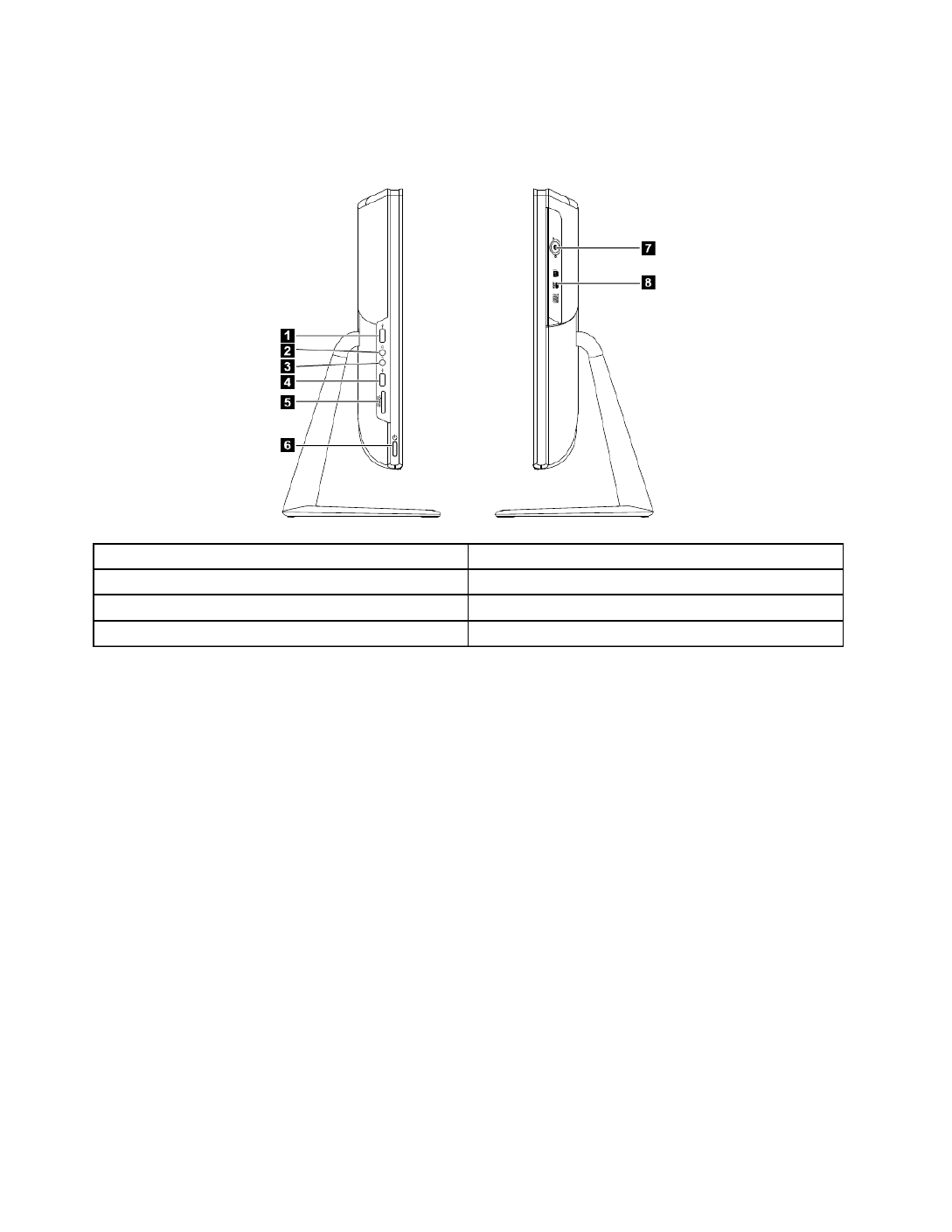
Leftandrightview
Thefollowingillustrationshowsthelocationofconnectors,controlsandcomponentsontheleftandright
sideofthecomputer.
1.USBconnector 5.Memorycardreader
2.Headphoneconnector6.Powerbutton
3.Microphoneconnector 7.Opticaldriveejectbutton
4.USBconnectorve
Attention:Donotinsert3-inchdiscsintotheopticaldrive.
22LenovoC355/C455All-In-OneComputerHardwareMaintenanceManual

Rearview
Thefollowingillustrationshowsthelocationofconnectorsandcomponentsontherearofthecomputer.
1.TVtunerconnector(selectedmodelsonly,2connectors
forJapan)
6.USBconnector
2.TVtunerconnector(selectedmodelsonly,2connectors
forJapan)
7.HDMI-outconnector(selectedmodelsonly)
3.Powerconnector 8.Securitycableslot
4.Ethernetconnector9.Airvents
5.USBconnector
Chapter7.Locatingconnectors,controlsandcomponents23

Hardwarecomponents
Thefollowingillustrationshowsthecomponentsthatmakeupyourcomputer.
1.Opticaldiskdrivebracket 12.Frontbezel
2.Opticaldiskdrive 13.Memorymodule
3.Harddiskdrivebracket14.Wi-Ficard
4.Harddiskdriveard
5.Heat-sink 16.Converterboard
6.Systemfan
7.Speakers 18.Motherboard
8.RearI/Omodulebracket 19.EMIcover
9.RearI/Omodule 20.Footcover
10.Chassis 21.Middlecover
11.LEDpanel 22.Computerstand
24LenovoC355/C455All-In-OneComputerHardwareMaintenanceManual

Identifyingpartsonthemotherboard
Themotherboard(sometimescalledtheplanarorsystemboard)isthemaincircuitboardinyourcomputer.
Itprovidesbasiccomputingfunctionsandsupportsavarietyofdevicesthatarefactory-installedorthat
youcaninstalllater.Thefollowingillustrationshowsthelocationofconnectorsandcomponentsonthe
frontofthemotherboard.
1.Cameraconnector0.DC-inconnector
2.Opticaldiskdrivepowerconnector11.RearI/Omoduleconnector
3.Systemfanconnector 12.TV- T unercardconnector
4.LVDSconnectorCAScardreaderconnector
5.OpticaldriveSATAconnector 14.Wi-Ficardconnector
6.Battery 15.Frontfunctionboardconnector
7.HarddiskdriveSATAconnector 16.Powercontrolconnector
8.Harddiskdrivepowerconnector 17.Speakerconnector
9.Converterconnector 18.Memoryconnector
Chapter7.Locatingconnectors,controlsandcomponents25

26LenovoC355/C455All-In-OneComputerHardwareMaintenanceManual

Chapter8.Replacinghardware
Attention:Donotremovethecomputercoverorattemptanyrepairbeforereadingthe“Importantsafetyinformation”
intheSafetyandWarrantyGuidethatwasincludedwithyourcomputer.ToobtaincopiesoftheSafetyandWarranty
Guide,gototheSupportWebsiteat:http://consumersupport.lenovo.com.
Note:UseonlypartsprovidedbyLenovo.
Generalinformation
Pre-disassemblyinstructions
Beforestartingthedisassemblyprocedure,makesurethatyoudothefollowing:
1.Turnoffthepowertothesystemandallperipherals.
2.Unplugallpowerandsignalcablesfromthecomputer.
3.Placethesystemonaat,stablesurface.
©CopyrightLenovo2013 27
Replacingthekeyboardandmouse
Note:Y ourkeyboardwillbeconnectedtoaUSBconnectorateithersideorattherearofthecomputer.
Toreplacethekeyboard:
Step1.Removeanymedia(disks,CDs,ormemorycards)fromthedrives,shutdownthecomputer,and
turnoffallattacheddevices.
Step2.Unplugallpowercordsfromelectricaloutlets.
Step3.Locatetheconnectorforthekeyboard.Referto“Sideviewofthecomputer”and“Rearviewof
thecomputer”.
Step4.Disconnectthedefectivekeyboardcablefromthecomputerandconnectthenewkeyboardcable
tothesameconnector.
Step5.Themousecanbereplacedusingthesamemethod.
Replacingtheadapter
Attention:T urnoffthecomputerandwait3to5minutestoletitcooldownbeforeremovingthecover.
Step1.Removeanymedia(disks,CDs,ormemorycards)fromthedrives,shutdowntheoperating
system,andturnoffthecomputerandallattacheddevices.
28LenovoC355/C455All-In-OneComputerHardwareMaintenanceManual

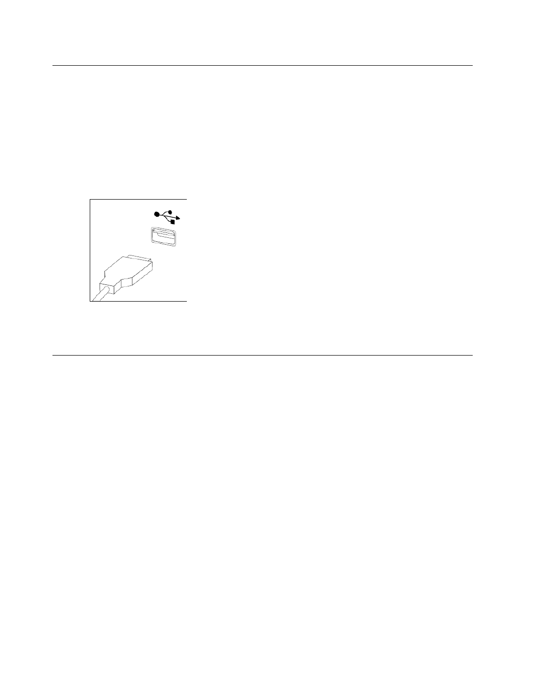
Step2.Disconnecttheadaptercablefromthecomputer1,thenunplugthepowercordfromelectrical
outlet.2
Step3.Connectthenewadapterasshown.12
Chapter8.Replacinghardware29

Removingthestandbase
Attention:Turnoffthecomputerandwait3to5minutestoletitcooldownbeforeremovingthecover.
Note:Itmaybehelpfultoplacethecomputerface-downonasoftatsurfaceforthisprocedure.Lenovo
recommendsthatyouuseablanket,towel,orothersoftclothtoprotectthetouchscreenfromscratches
orotherdamage.
Step1.Removeanymedia(disks,CDs,ormemorycards)fromthedrives,shutdowntheoperating
system,andturnoffthecomputerandallattacheddevices.
Step2.Unplugallpowercordsfromelectricaloutlets.
Step3.Disconnectallcablesattachedtothecomputer.Thisincludespowercords,input/output(I/O)
cables,andanyothercablesthatareconnectedtothecomputer.Referto“Leftandrightviews”
and“Rearview”forhelpwithlocatingthevariousconnectors.
Step4.Twistthehandscrewringcounter-clockwiseuntilthebasecomesloosetoreleasethestandbase
fromthestandholder.1
Step5.Slidethestandbaseoutfromtheholderthenputitaside.2
Step6.Referto“Installingthecomputerstand”toreinstallthestandbase.
Removingthefootcover
Attention:Turnoffthecomputerandwait3to5minutestoletitcooldownbeforeremovingthecover.
30LenovoC355/C455All-In-OneComputerHardwareMaintenanceManual

Note:Itmaybehelpfultoplacethecomputerface-downonasoftatsurfaceforthisprocedure.Lenovo
recommendsthatyouuseablanket,towel,orothersoftclothtoprotectthetouchscreenfromscratches
orotherdamage.
Step1.Removeanymedia(disks,CDs,ormemorycards)fromthedrives,shutdowntheoperating
system,andturnoffthecomputerandallattacheddevices.
Step2.Unplugallpowercordsfromelectricaloutlets.
Step3.Disconnectallcablesattachedtothecomputer.Thisincludespowercords,input/output(I/O)
cables,andanyothercablesthatareconnectedtothecomputer.Referto“Leftandrightviews”
and“Rearview”forhelpwithlocatingthevariousconnectors.
Step4.Removethefootbase.Referto“Removingthefootbase”.
Step5.Liftupthestandholderthenslideoutthefootcoverasshown.
Step6.Toreattachthefootcover:
a.Liftupthestandholder.
b.Lineupthefootcoverwithmountingholesonthebackofthecomputer,thenslideitbackinto
position.
Replacingamemorymodule
Attention:T urnoffthecomputerandwait3to5minutestoletitcooldownbeforeremovingthecover.
Chapter8.Replacinghardware31

Replacingtheharddiskdrive
Attention:Turnoffthecomputerandwait3to5minutestoletitcooldownbeforeremovingthecover.
Note:Itmaybehelpfultoplacethecomputerface-downonasoftatsurfaceforthisprocedure.Lenovo
recommendsthatyouuseablanket,towel,orothersoftclothtoprotectthetouchscreenfromscratches
orotherdamage.
Step1.Removeanymedia(disks,CDs,ormemorycards)fromthedrives,shutdowntheoperating
system,andturnoffthecomputerandallattacheddevices.
Step2.Unplugallpowercordsfromelectricaloutlets.
Step3.Disconnectallcablesattachedtothecomputer.Thisincludespowercords,input/output(I/O)
cables,andanyothercablesthatareconnectedtothecomputer.Referto“Leftandrightviews”
and“Rearview”forhelpwithlocatingthevariousconnectors.
Step4.Removethestandbase.Referto“Removingthestandbase” .
Step5.Removethefootcover.Referto“Removingthefootcover” .
Step6.Pushtheharddiskdrivebracket1,thenslidetheharddiskdriveandbracketoutofthechassisas
shown.2
Chapter8.Replacinghardware33

Step7.Pushthelockpinsoutwardtoreleasetheharddiskdrivefromthebracket.
Step8.Toinstallthenewharddiskdrive:
a.Lineupthenewharddiskdrivewiththebracketandsecureitwiththepins.
b.Slidetheharddiskdriveandbracketbackintoposition.
Step9.Reattachthefootcoverandstandbase.
Replacingtheopticaldrive
Attention:T urnoffthecomputerandwait3to5minutestoletitcooldownbeforeremovingthecover.
Note:Itmaybehelpfultoplacethecomputerface-downonasoftatsurfaceforthisprocedure.Lenovo
recommendsthatyouuseablanket,towel,orothersoftclothtoprotectthetouchscreenfromscratches
orotherdamage.
Step1.Removeanymedia(disks,CDs,ormemorycards)fromthedrives,shutdowntheoperating
system,andturnoffthecomputerandallattacheddevices.
Step2.Unplugallpowercordsfromelectricaloutlets.
Step3.Disconnectallcablesattachedtothecomputer.Thisincludespowercords,input/output(I/O)
cables,andanyothercablesthatareconnectedtothecomputer.Referto“Leftandrightviews”
and“Rearview”forhelpwithlocatingthevariousconnectors.
Step4.Removethestandbase.Referto“Removingthestandbase” .
Step5.Removethefootcover.Referto“Removingthefootcover” .
34LenovoC355/C455All-In-OneComputerHardwareMaintenanceManual

Step6.Pushtheopticaldrivepindownwardtopushouttheopticaldriveasshown.12
Step7.Pushasmallironstick(paperclip)intothesmallholeontheopticaldrivecoversothatthedisk
springsoutasshown.
Step8.Removethe2screwsthatsecuretheopticaldrivetothemetalbracket.1
Step9.Useasmallatheadscrewdrivertopressandpushoutthepinsthatsecurethecovertothe
disk.23
Chapter8.Replacinghardware35

Step7.Toreattachthestandholder:
a.Aligntheholesonthestandholderwithmountingholesonthechassis,placethestand
holderbackintoposition.
b.Securethestandholdertothechassiswiththefourscrews.
Step8.Lineupthefootcoverwithmountingholesonthebackofthecomputer,thenslideitbackinto
position.
Step9.Reattachthestandbase.
Removingthemiddlecover
Note:Turnoffthecomputerandwait3to5minutestoletitcooldownbeforeremovingthecover.
Note:Itmaybehelpfultoplacethecomputerface-downonasoftatsurfaceforthisprocedure.Lenovo
recommendsthatyouuseablanket,towel,orothersoftclothtoprotectthecomputerscreenfromscratches
orotherdamage.
Toremovethemiddlecover:
Step1.Removeanymedia(disks,CDs,DVDs,ormemorycards)fromthedrives,shutdowntheoperating
system,andturnoffthecomputerandallattacheddevices.
Step2.Unplugallpowercordsfromelectricaloutlets.
Step3.Disconnectallcablesattachedtothecomputer.Thisincludespowercords,input/output(I/O)
cables,andanyothercablesthatareconnectedtothecomputer.Referto“Leftandrightview”
and“Rearview”forhelpwithlocatingthevariousconnectors.
Step4.Removethestandbase.Referto“Removingthestandbase” .
Step5.Removethefootcover.Referto“Removingthefootcover”.
Step6.Removetheopticaldrive.Referto“Replacingtheopticaldrive” .
Step7.Removethestandholder.Referto“Removingthestandholder”.
Step8.Removethesevenscrewsthatsecurethemiddlecovertothechassis,thenliftupthemiddlecover
fromtheleftside(opticaldriveside)toremovethemiddlecover.
Chapter8.Replacinghardware37

Step9.Toreattachthemiddlecover:
a.Lineupthemiddlecoverwithchassis,thenplacethemiddlecoverback.
b.Securethemiddlecovertothechassiswiththesevenscrews.
Step10.Reattachthestandholder,opticaldrive,footcoverandstandbase.
Replacingtheconverterboard
Note:Turnoffthecomputerandwait3to5minutestoletitcooldownbeforeremovingthecover.
Note:Itmaybehelpfultoplacethecomputerface-downonasoftatsurfaceforthisprocedure.Lenovo
recommendsthatyouuseablanket,towel,orothersoftclothtoprotectthecomputerscreenfromscratches
orotherdamage.
Toreplacetheconverterboard:
Step1.Removeanymedia(disks,CDs,DVDs,ormemorycards)fromthedrives,shutdowntheoperating
system,andturnoffthecomputerandallattacheddevices.
Step2.Unplugallpowercordsfromelectricaloutlets.
Step3.Disconnectallcablesattachedtothecomputer.Thisincludespowercords,input/output(I/O)
cables,andanyothercablesthatareconnectedtothecomputer.Referto“Leftandrightview”
and“Rearview”forhelpwithlocatingthevariousconnectors.
Step4.Removethestandbase.Referto“Removingthestandbase” .
Step5.Removethefootcover.Referto“Removingthefootcover”.
Step6.Removetheopticaldrive.Referto“Replacingtheopticaldrive” .
Step7.Removethestandholder.Referto“Removingthestandholder”.
Step8.Removethemiddlecover.Referto“Removingthemiddlecover”.
38LenovoC355/C455All-In-OneComputerHardwareMaintenanceManual

Step9.Disconnectthetwocablesfromtheconverter,andthenremovethetwoscrewsthatsecurethe
converterboardtothechassis.
Step10.Liftuptheconverterboardtoremoveit.
Step11.Toinstallthenewconverterboard:
a.Lineuptheholesonthenewconverterboardwiththemountingholesonthechassisand
secureitwiththetwoscrews.
b.Connectthetwocablestothenewconverterboard.
Step12.Reattachthemiddlecover,opticaldrive,standholder,footcoverandstandbase.
Replacingthecamera
Note:Turnoffthecomputerandwait3to5minutestoletitcooldownbeforeremovingthecover.
Note:Itmaybehelpfultoplacethecomputerface-downonasoftatsurfaceforthisprocedure.Lenovo
recommendsthatyouuseablanket,towel,orothersoftclothtoprotectthecomputerscreenfromscratches
orotherdamage.
Toreplacethecamera:
Step1.Removeanymedia(disks,CDs,DVDs,ormemorycards)fromthedrives,shutdowntheoperating
system,andturnoffthecomputerandallattacheddevices.
Step2.Unplugallpowercordsfromelectricaloutlets.
Step3.Disconnectallcablesattachedtothecomputer.Thisincludespowercords,input/output(I/O)
cables,andanyothercablesthatareconnectedtothecomputer.Referto“Leftandrightview”
and“Rearview”forhelpwithlocatingthevariousconnectors.
Step4.Removethestandbase.Referto“Removingthestandbase” .
Step5.Removethefootcover.Referto“Removingthefootcover”.
Step6.Removetheopticaldrive.Referto“Replacingtheopticaldrive”.
Step7.Removethestandholder.Referto“Removingthestandholder”.
Step8.Removethemiddlecover.Referto“Removingthemiddlecover”.
Step9.Removetheheat-sink.Referto“Replacingtheheatsink”.
Chapter8.Replacinghardware39

Step10.Removethetwoscrewsthatsecurecameratothefrontbezel.1
Step11.Liftupthecamera2anddisconnectthedatacablefromthecamera.3
Step12.Toinstallthenewcamera:
a.Connectthedatacabletothenewcamera.
b.Lineuptheholesinthenewcamerawiththemountingholesonthefrontbezelandsecureit
withthetwoscrews.
Step13.Reattachthemiddlecover,opticaldrive,standholder,footcoverandstandbase.
RemovingtheEMIcover
Note:Turnoffthecomputerandwait3to5minutestoletitcooldownbeforeremovingthecover.
Note:Itmaybehelpfultoplacethecomputerface-downonasoftatsurfaceforthisprocedure.Lenovo
recommendsthatyouuseablanket,towel,orothersoftclothtoprotectthecomputerscreenfromscratches
orotherdamage.
ToreplacetheEMIcover
Step1.Removeanymedia(disks,CDs,DVDs,ormemorycards)fromthedrives,shutdowntheoperating
system,andturnoffthecomputerandallattacheddevices.
Step2.Unplugallpowercordsfromelectricaloutlets.
40LenovoC355/C455All-In-OneComputerHardwareMaintenanceManual

Step3.Disconnectallcablesattachedtothecomputer.Thisincludespowercords,input/output(I/O)
cables,andanyothercablesthatareconnectedtothecomputer.Referto“Leftandrightview”
and“Rearview”forhelpwithlocatingthevariousconnectors.
Step4.Removethestandbase.Referto“Removingthestandbase” .
Step5.Removethefootcover.Referto“Removingthefootcover” .
Step6.Removetheopticaldrive.Referto“Replacingtheopticaldrive” .
Step7.Removethestandholder.Referto“Removingthestandholder”.
Step8.Removethemiddlecover.Referto“Removingthemiddlecover”.
Step9.RemovethethreescrewsthatsecuretheEMIcovertothechassis1,andthenliftitup.2
Step10.ToreattachtheEMIcover:
a.LineuptheholesontheEMIcoverwithmountingholesonthechassis,thenplaceEMIcover
backintoposition.
b.SecuretheEMIcovertothechassiswiththreescrews.
Step11.Reattachthemiddlecover,opticaldrive,standholder,footcoverandstandbase.
ReplacingtherearI/Omodule
Note:T urnoffthecomputerandwait3to5minutestoletitcooldownbeforeremovingthecover.
Note:Itmaybehelpfultoplacethecomputerface-downonasoftatsurfaceforthisprocedure.Lenovo
recommendsthatyouuseablanket,towel,orothersoftclothtoprotectthecomputerscreenfromscratches
orotherdamage.
ToreplacetherearI/Omodule
Step1.Removeanymedia(disks,CDs,DVDs,ormemorycards)fromthedrives,shutdowntheoperating
system,andturnoffthecomputerandallattacheddevices.
Step2.Unplugallpowercordsfromelectricaloutlets.
Step3.Disconnectallcablesattachedtothecomputer.Thisincludespowercords,input/output(I/O)
cables,andanyothercablesthatareconnectedtothecomputer.Referto“Leftandrightview”
and“Rearview”forhelpwithlocatingthevariousconnectors.
Step4.Removethestandbase.Referto“Removingthestandbase” .
Step5.Removethefootcover.Referto“Removingthefootcover”.
Chapter8.Replacinghardware41
Specyfikacje produktu
| Marka: | Lenovo |
| Kategoria: | ambona |
| Model: | IdeaCentre C355 |
| Kolor produktu: | Biały |
| Typ produktu: | All-in-One PC |
| Bluetooth: | Nie |
| Wbudowane głośniki: | Tak |
| Moc wyjściowa (RMS): | 6 W |
| Wyjścia słuchawkowe: | 1 |
| Typ HD: | HD+ |
| Długość przekątnej ekranu: | 20 " |
| Prędkość transferu danych przez Ethernet LAN: | 10,100,1000 Mbit/s |
| Ilość portów Ethernet LAN (RJ-45): | 1 |
| Rozdzielczość: | 1600 x 900 px |
| Natywne proporcje obrazu: | 16:9 |
| Ekran dotykowy: | Nie |
| Taktowanie procesora: | 1.4 GHz |
| Typ procesora: | AMD E |
| Model procesora: | E1-2500 |
| Wi-Fi: | Tak |
| Standardy Wi- Fi: | 802.11b, 802.11g, Wi-Fi 4 (802.11n) |
| Liczba portów USB 2.0: | 4 |
| Przewodowa sieć LAN: | Tak |
| Zintegrowany czytnik kart: | Tak |
| Interfejs napędów pamięci masowej: | SATA |
| Producent procesora: | AMD |
| Liczba rdzeni procesora: | 2 |
| Typ pamięci wewnętrznej: | DDR3-SDRAM |
| Pamięć wewnętrzna: | 2 GB |
| Ilość portów USB 3.2 Gen 1 (3.1 Gen 1) Typu-A: | 2 |
| Zainstalowany system operacyjny: | Windows 8 |
| Typ slotów pamięci: | SO-DIMM |
| Maksymalna pojemność pamięci: | 8 GB |
| Ilość portów HDMI: | 1 |
| Mikrofon: | Tak |
| Dołączona myszka: | Tak |
| Wbudowana kamera/aparat: | Tak |
| Szerokość urządzenia (z podstawą): | 499 mm |
| Głębokość urządzenia (z podstawą): | 196 mm |
| Wysokość urządzenia (z podstawą): | 397 mm |
| Waga (z podstawą): | 4900 g |
| Nośniki: | HDD |
| System dźwięku: | Dolby Advanced Audio v2 |
| Wbudowany mikrofon: | Tak |
| Podświetlenie LED: | Tak |
| Suma megapikseli: | - MP |
| Pełny HD: | Nie |
| Szybkość HDD: | 7200 RPM |
| Całkowita pojemność przechowywania: | 500 GB |
| Technologia Intel® Hyper Threading (Intel® HT Technology): | Nie |
| Technologia Intel® Turbo Boost: | Nie |
| Interfejs HDD: | SATA |
| Typ pamięci procesora: | L2 |
| Cache procesora: | 1 MB |
| Liczba wątków: | 2 |
| Układ pamięci: | 1 x 2 GB |
| Prędkość zegara pamięci: | 1600 MHz |
| Karta graficzna on-board: | Tak |
| Model karty graficznej on-board: | AMD Radeon HD 8240 |
| Typ zintegrowanej karty graficznej: | AMD Radeon HD 8000 |
| Intel® Small Business Advantage (Intel® SBA): | Nie |
| Intel® Wireless Display (Intel® WiDi): | Nie |
| Technologia Intel® My WiFi (Intel® MWT): | Nie |
| Technologia Intel® Identity Protection (Intel® IPT): | Nie |
| Technologia Intel® Anti-Theft (Intel® AT): | Nie |
| Liczba zainstalowanych dysków: | 1 |
| Napędy optyczne: | DVD-RW |
| Architektura systemu operacyjnego: | 64-bit |
| W zestawie klawiatura: | Tak |
| Technologia Intel® Smart Connect: | Nie |
| Technologia Intel® Rapid Start: | Nie |
| Technologia Intel® Smart Response: | Nie |
| Liczba zainstalowanych HDD: | 1 |
| Architektura 64-bitowa: | Tak |
| Tryb podtrzymania: | Nie |
| Rozdzielczość zdjęcia: | 1280 x 720 px |
Potrzebujesz pomocy?
Jeśli potrzebujesz pomocy z Lenovo IdeaCentre C355, zadaj pytanie poniżej, a inni użytkownicy Ci odpowiedzą
Instrukcje ambona Lenovo

7 Lutego 2025
31 Stycznia 2025
28 Sierpnia 2024
28 Sierpnia 2024
28 Sierpnia 2024
28 Sierpnia 2024
28 Sierpnia 2024
28 Sierpnia 2024
28 Sierpnia 2024
28 Sierpnia 2024
Instrukcje ambona
- ambona Gigabyte
- ambona Acer
- ambona Fujitsu
- ambona LC-Power
- ambona Viewsonic
- ambona Asus
- ambona Medion
- ambona MSI
- ambona Haier
- ambona HP
- ambona Tripp Lite
- ambona Dell
- ambona Apple
- ambona Razer
- ambona Asrock
- ambona ECS
- ambona Elo
- ambona Cybernet
- ambona Planar
- ambona Zotac
- ambona Kramer
- ambona TrekStor
- ambona Alienware
- ambona Intel
- ambona Advantech
- ambona AOpen
- ambona Kendall Howard
Najnowsze instrukcje dla ambona

9 Kwietnia 2025
2 Kwietnia 2025

1 Kwietnia 2025
1 Kwietnia 2025

1 Kwietnia 2025

29 Marca 2025
27 Marca 2025
6 Marca 2025
26 Lutego 2025
26 Lutego 2025