Instrukcja obsługi JVC GR-DV2000
JVC
kamera wideo
GR-DV2000
Przeczytaj poniżej 📖 instrukcję obsługi w języku polskim dla JVC GR-DV2000 (98 stron) w kategorii kamera wideo. Ta instrukcja była pomocna dla 17 osób i została oceniona przez 2 użytkowników na średnio 4.5 gwiazdek
Strona 1/98

LYT0708-001A EN
DIGITAL VIDEO CAMERA
INSTRUCTIONS
GR-DV2000
For Customer Use:
Enter below the Model No. and Serial No. which is located on the
bottom of cabinet. Retain this information for future reference.
Model No.
Serial No.
ENGLISH
CONTENTS
AUTOMATIC DEMONSTRATION
7
GETTING STARTED
8 – 17
RECORDING
18 – 39
Basic Recording For Video .................... 18
Basic Recording For Digital Still Camera
(D.S.C.) ........................................ 21
Basic Recording For Video And D.S.C. ...... 22
Advanced Features For Video And D.S.C. .. 24
PLAYBACK
40 – 53
Basic Playback For Video ..................... 40
Advanced Features For Video ................ 41
Basic Playback For D.S.C. ..................... 44
Advanced Features For D.S.C. ............... 46
CONNECTIONS
54 – 57
Basic Connections .............................. 54
Advanced Connections ......................... 56
DUBBING
58 – 60
Dubbing To Or From A VCR................... 58
Dubbing To Or From A Video Unit
Equipped With A DV Connector ............ 59
Dubbing Images Recorded
On A Tape To A Memory Card .............. 60
USING THE REMOTE
CONTROL UNIT
61 – 72
Slow-Motion Playback, Frame-By-Frame
Playback and Playback Zoom .............. 63
Playback Special Effects ...................... 64
Random Assemble Editing .................... 65
For More Accurate Editing .................... 69
Audio Dubbing .................................. 71
Insert Editing ................................... 72
TROUBLESHOOTING
73 – 79
USER MAINTENANCE
80
INDEX
81 – 88
Jack Box ......................................... 81
Controls, Connectors And Indicators ........ 82
Indications ...................................... 84
CAUTIONS
89 – 91
TERMS
92 – 93
SPECIFICATIONS
94 – 95
Please visit our Homepage on the World Wide
Web and answer our Consumer Survey
(in English only):
http://www.jvc-victor.co.jp/english/index-e.html

2 EN
This camcorder is designed to be used with NTSC-
type color television signals. It cannot be used for
playback with a television of a different standard.
However, live recording and LCD monitor/
viewfinder playback are possible anywhere. Use the
JVC BN-V408U/V416U/V428U battery packs and,
to recharge them, the provided multi-voltage AC
Power Adapter/Charger. (An appropriate conversion
adapter may be necessary to accommodate different
designs of AC outlets in different countries.)
Using This Instruction Manual
• All major sections and subsections are listed in the Table Of Contents on the cover page.
• Notes appear after most subsections. Be sure to read these as well.
• Basic and advanced features/operation are separated for easier reference.
It is recommended that you . . .
..... refer to the Index ( pgs. 81 – 88) and familiarize yourself with button locations, etc. before use.
..... read thoroughly the Safety Precautions and Safety Instructions that follow. They contain extremely important
information regarding the safe use of this product.
SAFETY PRECAUTIONS
CAUTION
RISK OF ELECTRIC SHOCK
DO NOT OPEN
CAUTION: TO REDUCE THE RISK OF ELECTRIC SHOCK,
DO NOT REMOVE COVER (OR BACK).
NO USER-SERVICEABLE PARTS INSIDE.
REFER SERVICING TO QUALIFIED SERVICE PERSONNEL.
The lightning flash with arrowhead symbol, within an
equilateral triangle, is intended to alert the user to the
presence of uninsulated "dangerous voltage" within the
product's enclosure that may be of sufficient magnitude
to constitute a risk of electric shock to persons.
The exclamation point within an equilateral triangle is
intended to alert the user to the presence of important
operating and maintenance (servicing) instructions in
the literature accompanying the appliance.
You are recommended to carefully read the cautions on pages 89 through 91 before use.
NOTES:
●
The rating plate (serial number plate) and safety
caution are on the bottom and/or the back of the
main unit.
●
The rating plate (serial number plate) of the AC
Power Adapter/Charger is on its bottom.
WARNING:
TO PREVENT FIRE OR SHOCK
HAZARD, DO NOT EXPOSE THIS
UNIT TO RAIN OR MOISTURE.
The AA-V40U AC Power Adapter/Charger should be
used with:
AC 120 V`, 60 Hz in the USA and Canada,
AC 110 V – 240 V`, 50 Hz/60 Hz in other countries.
CAUTION (applies to the AA-V40U)
TO PREVENT ELECTRIC SHOCK MATCH WIDE
BLADE OF PLUG TO WIDE SLOT, FULLY INSERT.
ATTENTION (s’applique à l’AA-V40U)
POUR LECTRIQUES,ÉVITER LES CHOCS É
INTRODUIRE LA LAME LA PLUS LARGE DE LA
FICHE DANS LA BORNE CORRESPONDANTE DE
LA PRISE ET POUSSER JUSQU AU FOND.’
Dear Customer,
Thank you for purchasing this digital video camera. Before use, please read the safety information and precautions
contained in the following pages to ensure safe use of this product.
When the equipment is installed in a cabinet or on
a shelf, make sure that it has sufficient space on all
sides to allow for ventilation (10 cm (3-15/16") or
more on both sides, on top and at the rear).
Do not block the ventilation holes.
(If the ventilation holes are blocked by a newspaper,
or cloth etc. the heat may not be able to get out.)
No naked flame sources, such as lighted candles,
should be placed on the apparatus.
When discarding batteries, environmental problems
must be considered and the local rules or laws
governing the disposal of these batteries must be
followed strictly.
The apparatus shall not be exposed to dripping or
splashing.
Do not use this equipment in a bathroom or places
with water.
Also do not place any containers filled with water or
liquids (such as cosmetics or medicines, flower
vases, potted plants, cups etc.) on top of this unit.
(If water or liquid is allowed to enter this equip-
ment, fire or electric shock may be caused.)
Caution: (applies to Jack Box)
To reduce the risk of fire, do not remove
cover. No user-serviceable parts inside.
Refer servicing to qualified service person.
EN3
5. Ventilation
Slots and openings in the cabinet are provided for
ventilation. To ensure reliable operation of the product
and to protect it from overheating, these openings must
not be blocked or covered.
•Do not block the openings by placing the product on a
bed, sofa, rug or other similar surface.
•Do not place the product in a built-in installation such
as a bookcase or rack unless proper ventilation is
provided or the manufacturer’s instructions have been
adhered to.
6. Wall or Ceiling Mounting
The product should be mounted to a wall or ceiling only
as recommended by the manufacturer.
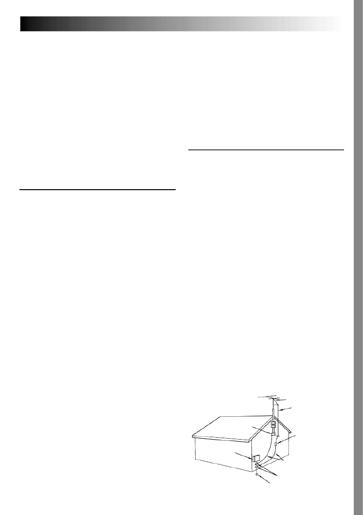
ANTENNA INSTALLATION
INSTRUCTIONS
1. Outdoor Antenna Grounding
If an outside antenna or cable system is connected to the
product, be sure the antenna or cable system is
grounded so as to provide some protection against
voltage surges and built-up static charges. Article 810 of
the National Electrical Code, ANSI/NFPA 70, provides
information with regard to proper grounding of the mast
and supporting structure, grounding of the lead-in wire
to an antenna discharge unit, size of grounding
conductors, location of antenna discharge unit,
connection to grounding electrodes, and requirements
for the grounding electrode.
2. Lightning
For added protection for this product during a lightning
storm, or when it is left unattended and unused for long
periods of time, unplug it from the wall outlet and
disconnect the antenna or cable system. This will
prevent damage to the product due to lightning and
power-line surges.
3. Power Lines
An outside antenna system should not be located in the
vicinity of overhead power lines or other electric light or
power circuits, or where it can fall into such power lines
or circuits. When installing an outside antenna system,
extreme care should be taken to keep from touching
such power lines or circuits as contact with them might
be fatal.
IMPORTANT PRODUCT
SAFETY INSTRUCTIONS
Electrical energy can perform many useful functions.
But improper use can result in potential electrical
shock or fire hazards. This product has been
engineered and manufactured to assure your
personal safety. In order not to defeat the built-in
safeguards, observe the following basic rules for its
installation, use and servicing.
ATTENTION:
Follow and obey all warnings and instructions
marked on your product and its operating instruc-
tions. For your safety, please read all the safety and
operating instructions before you operate this
product and keep this manual for future reference.
INSTALLATION
1. Grounding or Polarization
(A) Your product may be equipped with a polarized
alternating-current line plug (a plug having one blade
wider than the other). This plug will fit into the
power outlet only one way. This is a safety feature.
If you are unable to insert the plug fully into the
outlet, try reversing the plug. If the plug should still
fail to fit, contact your electrician to replace your
obsolete outlet. Do not defeat the safety purpose of
the polarized plug.
(B) Your product may be equipped with a 3-wire
grounding-type plug, a plug having a third (ground-
ing) pin. This plug will only fit into a grounding-type
power outlet. This is a safety feature.
If you are unable to insert the plug into the outlet,
contact your electrician to replace your obsolete
outlet. Do not defeat the safety purpose of the
grounding-type plug.
2. Power Sources
Operate your product only from the type of power
source indicated on the marking label. If you are not
sure of the type of power supply to your home, consult
your product dealer or local power company. If your
product is intended to operate from battery power, or
other sources, refer to the operating instructions.
3. Overloading
Do not overload wall outlets, extension cords, or integral
convenience receptacles as this can result in a risk of fire
or electric shock.
4. Power Cord Protection
Power supply cords should be routed so that they are
not likely to be walked on or pinched by items placed
upon or against them, paying particular attention to
cords at plugs, convenience receptacles, and the point
where they exit from the product.
ANTENNA
LEAD IN WIRE
ANTENNA
DISCHARGE UNIT
(NEC SECTION
810-20)
GROUNDING CONDUCTORS
(NEC SECTION 810-21)
GROUND CLAMPS
POWER SERVICE GROUNDING ELECTRODE SYSTEM
(NEC ART 250. PART H)
NEC – NATIONAL ELECTRICAL CODE
ELECTRIC SERVICE
EQUIPMENT
EXAMPLE OF ANTENNA GROUNDING AS PER
NATIONAL ELECTRICAL CODE, ANSI/NFPA 70
GROUND CLAMP

EN7
AUTOMATIC DEMONSTRATION
Automatic Demonstration takes place when DEMO MODE“ ” is
set to “ ”ON (factory-preset).
Available when the Power Switch is set to “ ” “ ” or and
no cassette is in the camcorder.
Performing any operation during the demonstration stops the
demonstration temporarily. If no operation is performed for
more than 1 minute after that, the demonstration will resume.
“ ” “DEMO MODE remains ON even if the camcorder power”
is turned off.
To cancel Automatic Demonstration:
1. Set the Power Switch to “ ” while pressing down the Lock
Button located on the switch and press the wheel.MENU
The Menu Screen appears.
2. Rotate the wheel to select MENU “ SYSTEM and press”
it. The SYSTEM Menu appears.
3. Rotate the MENU wheel to select “DEMO MODE” and
press it. The Sub Menu appears.
4. Rotate the MENU wheel to select “OFF” and press it.
5. Rotate the MENU wheel to select “
1
RETURN”, and press it
twice. The normal screen appears.
How To Attach The Lens Hood
The provided lens hood helps block out glare when shooting under bright sunlight, the same way professional
photographers do.
MODEDEMO –
ON
OF F
MENU Wheel
Sub Menu
Align the lens hood with the
camcorder’s lens and screw
it in clockwise.
Threading

EN15
REC MODE – SP
LP
Recording Mode Setting
Set the tape recording mode depending on your preference.
1
Set the Power Switch to while pressing down“ ”
the Lock Button located on the switch, and open the
LCD monitor fully or pull out the viewfinder fully.
The power lamp lights and the camcorder is turned
on.
2
Press the wheel. The Menu Screen appears.MENU
3
Rotate the MENU wheel to select CAMERA“ ” and
press it. The CAMERA Menu appears.
4
Rotate the MENU wheel to select REC MODE“ ” and
press it. The Sub Menu appears. Select “ ”SP or “LP”
by rotating the wheel and press it. Rotate theMENU
MENU wheel to select “
1
RETURN , and press it”
twice. The Menu Screen closes.
•Audio Dubbing ( pg. 71) and Insert Editing
( pg. 72) are impossible on a tape recorded in the
LP mode.
•“LP” (Long Play) is more economical, providing
1.5 times the recording time.
NOTES:
●
If the recording mode is switched during recording, the
playback picture will be blurred at the switching point.
●
It is recommended that tapes recorded in the LP mode
on this camcorder be played back on this camcorder.
●
During playback of a tape recorded on another
camcorder, blocks of noise may appear or there may be
momentary pauses in the sound.
Display
Menu Screen
Sub Menu
MENU Wheel
Power Switch
Lock Button
Power Lamp

EN17
NOTES:
●
If the Shooting Mode Switch is set to during“UXGA”
video recording, the camcorder stops video recording.
●
The camcorder automatically zooms out to less than 2X
when the Shooting Mode Switch is set to “UXGA”.
●
With images shot in the UXGA mode . . .
— the shutter speed is applicable only up to 1/500 in the
“ ”SPORTS mode (
pg. 37).
— Sepia and Monotone cannot be activated.
●
If DOUBLE“ ” is selected in the UXGA mode, images
may not be processed properly in the following
situations:
— when the subject has no contrast (difference in
brightness and darkness).
— when shooting in a dark place.
— when the subject contains identical patterns that are
regularly repeated.
— when shooting under a flickering light such as a
fluorescent light or candlelight.
— when the subject is moving rapidly.
— when there is excessive camera-shake.
●
If AUTO“ ” is selected in the UXGA mode, and any of
the shooting situations listed above are encountered, the
camcorder will automatically process the image using
the ENLARGE method.
STORAGE CAPACITY
The number of storable images depends on the selected
picture quality and size as well as the composition of the
subjects in the images.
Approximate number of storable images
(Provided 16 MB MultiMediaCard)
SIZE
UXGA (1600 x 1200)
XGA (1024 x 768)
VGA (640 x 480)
QUALITY
FINE
20
48
100
STANDARD
60
144
300
Approximate number of storable images
(Optional 8 MB MultiMediaCard)
SIZE
UXGA (1600 x 1200)
XGA (1024 x 768)
VGA (640 x 480)
QUALITY
FINE
10
24
50
STANDARD
30
72
150

EN31
: Factory-preset
BEEP Even though not heard while shooting, shutter sound is recorded on the tape.
The beep sounds when the power is turned on or off, and at the beginning and end
of recording. Also to activate the shutter sound effect ( pg. 20, 21).
Instead of a beep, a melody sounds when any operation is performed. It also
activates the shutter sound effect ( pg. 20, 21).
The tally lamp remains off at all times.
The tally lamp comes on to signal the start of recording.
Automatic demonstration will not take place.
Demonstrates certain functions such as Program AE with special effects, etc.,
and can be used to confirm how these functions operate. When “DEMO
MODE ON” is set to “ ” and the Menu Screen is closed, demonstration starts.
Performing any operation during the demonstration stops the demonstration
temporarily. If no operation is performed for more than 1 minute after that,
the demonstration will resume.
NOTES:
●If a tape is in the camcorder, the demonstration cannot be turned on.
●“ ” “ ”DEMO MODE remains ON even if the camcorder power is turned off.
●If “ ” “ ”DEMO MODE remains ON , some functions will not be available.
After viewing demo, set to “OFF”.
Keeps the camcorder s display (except the date, time and time code) from’
appearing on the connected TV screen.
Makes the camcorder’s display appear on screen when the camcorder is
connected to a TV.
The date/time does not appear.
Displays the date/time for approx. 5 seconds in the following cases:
• “ ” “ ” “ ”When the Power Switch is set from OFF to or .
•When video playback starts. The camcorder displays the date/time when
scenes are recorded.
•When the date is changed during video playback.
The date/time is always displayed.
Time code is not displayed.
Time code is displayed on the camcorder and on the connected TV. Frame
numbers are not displayed during recording.
Allows you to set the current date and time ( pg. 11).
Refer to “Picture Mode Setting” ( pg. 16).
NOTES:
●
“ ” “ SYSTEM and DISPLAY functions which are set when the Power Switch is set to are also” “ ”
applied when the Power Switch is set to “ ” (
pg. 41). only appears when the Power“CLOCK ADJ.”
Switch is set to “ ”.
●
The “ DISPLAY” settings are effective even when the Power Switch is set to “ ”.
●
The “ON SCREEN” setting can also be changed by pressing the DISPLAY Button on the remote control
(provided) (
pg. 55, 58, 66).
SYSTEM
OFF
BEEP
MELODY
OFF
ON
OFF
ON
LCD
LCD/TV
OFF
AUTO
ON
OFF
ON
TIME
CODE
CLOCK ADJ.
QUALITY
SIZE
UXGA
DSC DISPLAY
DATE/
TIME
ON
SCREEN
TALLY
DEMO
MODE
EN35
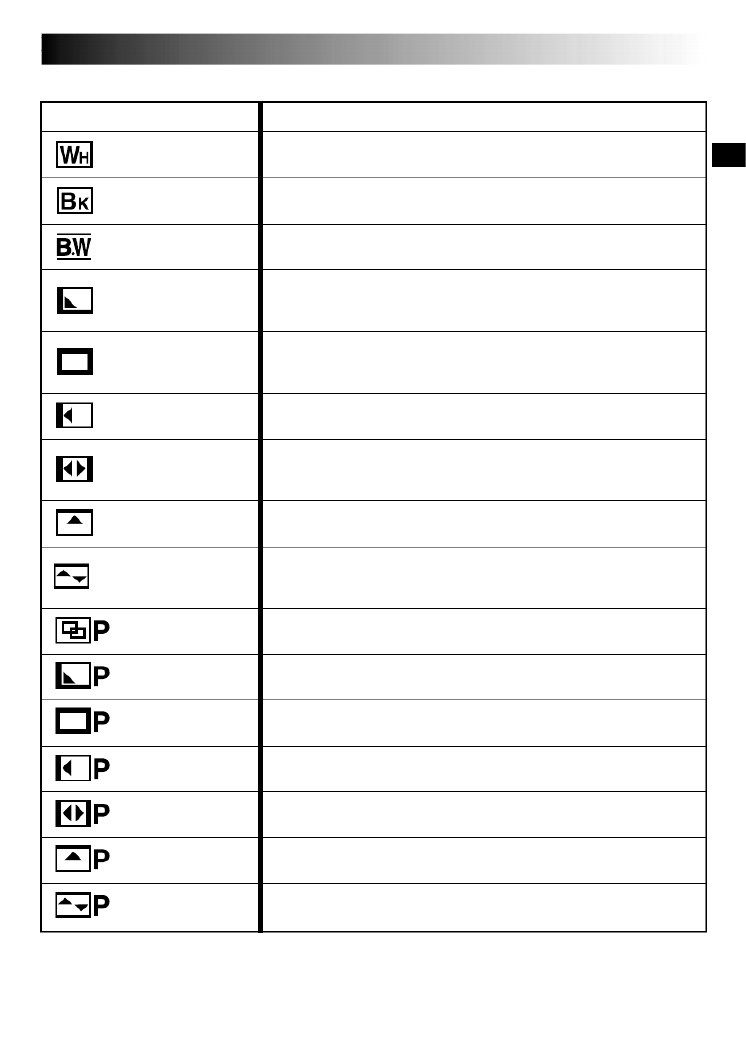
Fader And Wipe Menu
Menu Effect
Fade in or out with a white screen.
Fade in or out with a black screen.
Fade in to a color screen from a black and white screen, or fade out
from color to black and white.
Wipe in on a black screen from the upper right to the lower left
corner, or wipe out from lower left to upper right, leaving a black
screen.
The scene starts in the center of a black screen and wipes in toward
the corners, or comes in from the corners, gradually wiping out to the
center.
Wipe in from right to left, or wipe out from left to right.
Wipe in as the two halves of a black screen open to the left and right,
revealing the scene, or wipe out and the black screen reappears from
left and right to cover the scene.
The scene wipes in from the bottom to the top of a black screen, or
wipes out from top to bottom, leaving a black screen.
Wipe in from the center of a black screen toward the top and bottom,
or wipe out from the top and bottom toward the center leaving a
black screen.
The new scene gradually appears as the old one gradually disappears.
The new scene wipes in over the previous one from the upper right
corner to the lower left corner.
The next scene gradually wipes in from the center of the screen
toward the corners, covering the previous scene.
The next scene gradually wipes in over the previous one from right to
left.
The previous scene wipes out from the center to the right and left, like
a door being pushed open to reveal the next scene.
The new scene wipes in over the last one from the bottom of the
screen to the top.
The new scene wipes in over the previous one from the center toward
the top and bottom of the screen.
FADER — WHITE
FADER BLACK—
WIPE CORNER—
WIPE WINDOW—
WIPE SLIDE—
WIPE DOOR—
WIPE SCROLL—
WIPE SHUTTER—
FADER B.W—
DISSOLVE
WIPE — CORNER
WIPE — WINDOW
WIPE — SLIDE
WIPE — SHUTTER
WIPE — DOOR
WIPE — SCROLL
EN39
White Balance Adjustment
A term that refers to the correctness of color
reproduction under various lighting. If the white
balance is correct, all other colors will be accurately
reproduced.
The white balance is usually adjusted automatically.
However, more advanced camcorder operators
control this function manually to achieve a more
professional color/tint reproduction.
1
Set the Power Switch to while pressing“ ”
down the Lock Button located on the switch,
then pull out the viewfinder fully or open the
LCD monitor fully.
2
Press the MENU wheel. The Menu Screen
appears.
3
Rotate the wheel to select MENU “
W.BALANCE”, then press it. The W.BALANCE
Menu appears.
4
Rotate the the wheel to select theMENU
desired mode.
“AUTO” – White balance is adjusted
automatically (factory
preset).
“ MWB” – White balance is set
manually.
“ FINE” – Outdoors on a sunny day.
“ CLOUD” – Outdoors on a cloudy day.
“ HALOGEN” – A video light or similar type
of lighting is used.
5
Press the wheel. Selection is complete.MENU
Press the wheel again. The Menu ScreenMENU
closes and the selected mode indicator except
“AUTO” appears.
To Return To Automatic White Balance . . .
.... select “AUTO” in step 4. Or, set the Power
Switch to “ ”.
NOTE:
White balance cannot be used when Sepia or
Monotone (
pg. 37) is activated.
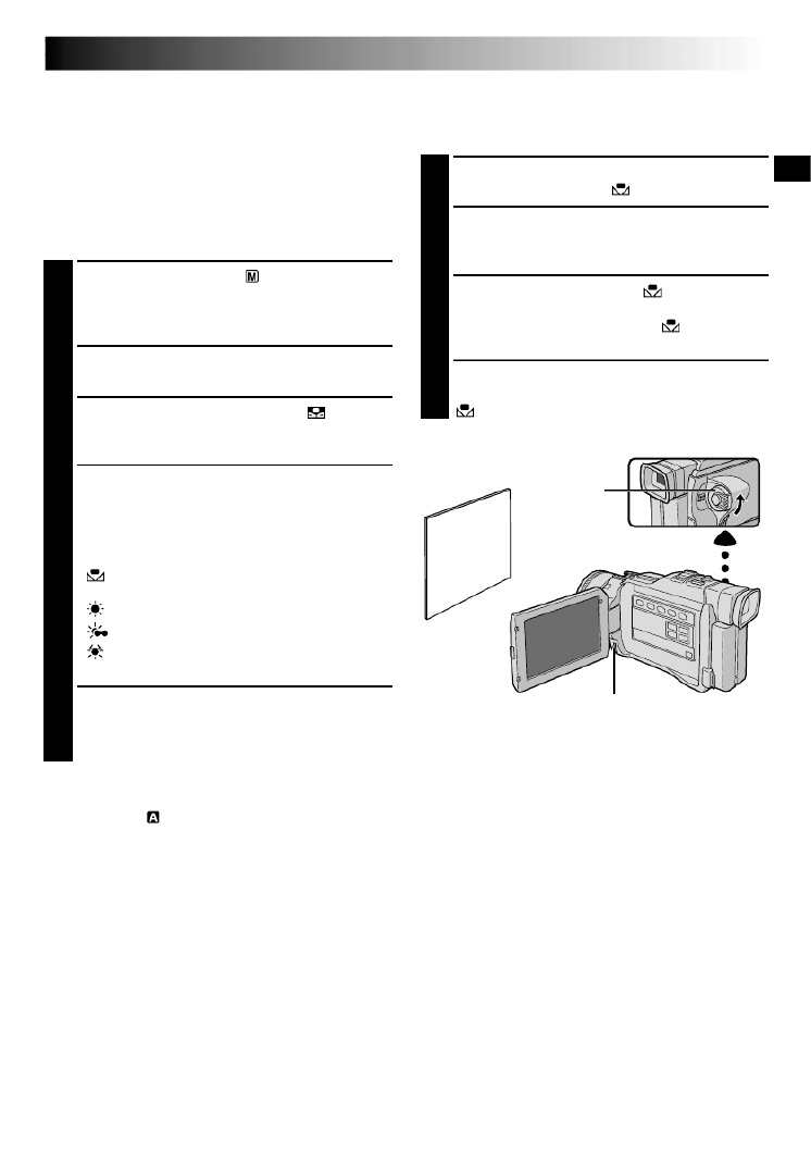
Manual White Balance Operation
Perform Manual White Balance when shooting under
various types of lighting.
1
Follow steps 1 4 through of the white balance
adjustment, and select “ MWB”.
2
Hold a sheet of plain white paper in front of the
subject. Adjust zoom or position yourself so that
the white paper fills the screen.
3
Press the wheel until begins blinkingMENU
rapidly.
When the setting is completed, stops
blinking.
4
Press the MENU wheel. The Menu Screen
closes and the Manual White Balance indicator
is displayed.
White
paper
Power Switch
MENU Wheel
To Change The Tint For Recording . . .
.... in step 2, substitute colored paper for white. The
white balance is adjusted based on the color,
changing the tint. Red paper = deeper green;
blue paper = orange; yellow paper = deeper
purple.
NOTES:
●
In step 2, it may be difficult to focus on the white
paper. In such a case, adjust focus manually
(
pg. 27).
●
A subject can be shot under various types of
lighting conditions indoors (natural, flourescent,
candlelight, etc.). Because the color temperature is
different depending on the light source, the subject
tint will differ depending on the white balance
settings. Use this function for a more natural result.
●
Once you adjust white balance manually, the
setting is retained even if the power is turned off or
the battery removed.
EN51
SE ECTL
AL L
– CANCE LD L .EF RAME
AL L
EX ECUT E
– C ANC E L
D L .EFRAME
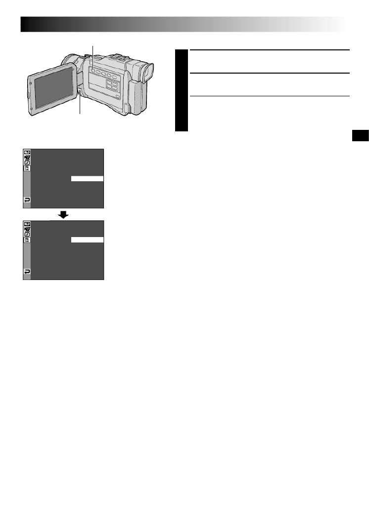
TO DELETE ALL PRINT FRAMES
1
Perform steps 1 through 5 on pag. 50.
2
Rotate the MENU wheel to select and press it.“ALL”
The Deletion Confirmation Screen appears.
3
Rotate the MENU wheel to select and“EXECUTE”
press it. All the print frames are deleted.
•To cancel deletion, rotate the MENU wheel to select
“ ”CANCEL and press it.
Display
Menu Screen
Deletion
Confirmation
Screen
MENU Wheel
MEMORY PLAY Button
Specyfikacje produktu
| Marka: | JVC |
| Kategoria: | kamera wideo |
| Model: | GR-DV2000 |
Potrzebujesz pomocy?
Jeśli potrzebujesz pomocy z JVC GR-DV2000, zadaj pytanie poniżej, a inni użytkownicy Ci odpowiedzą
Instrukcje kamera wideo JVC

10 Października 2024
20 Września 2024
17 Września 2024
16 Września 2024
13 Września 2024
12 Września 2024
9 Września 2024
8 Września 2024
8 Września 2024
8 Września 2024
Instrukcje kamera wideo
- kamera wideo Sony
- kamera wideo Samsung
- kamera wideo Leica
- kamera wideo Logitech
- kamera wideo Xiaomi
- kamera wideo Sharp
- kamera wideo Braun
- kamera wideo Voltcraft
- kamera wideo Milwaukee
- kamera wideo Philips
- kamera wideo SilverCrest
- kamera wideo Xblitz
- kamera wideo Panasonic
- kamera wideo Canon
- kamera wideo Mio
- kamera wideo Viewsonic
- kamera wideo Nedis
- kamera wideo Medion
- kamera wideo OK
- kamera wideo Lenco
- kamera wideo Fujifilm
- kamera wideo Toshiba
- kamera wideo Hazet
- kamera wideo Garmin
- kamera wideo Salora
- kamera wideo Evolveo
- kamera wideo HP
- kamera wideo Soundmaster
- kamera wideo Hyundai
- kamera wideo SJCAM
- kamera wideo Creative
- kamera wideo Swann
- kamera wideo Nikon
- kamera wideo Kodak
- kamera wideo Cisco
- kamera wideo SBS
- kamera wideo Kenwood
- kamera wideo DJI
- kamera wideo Gembird
- kamera wideo Minox
- kamera wideo Cobra
- kamera wideo Trust
- kamera wideo Linksys
- kamera wideo Thinkware
- kamera wideo AgfaPhoto
- kamera wideo Vimar
- kamera wideo Ricoh
- kamera wideo Renkforce
- kamera wideo Rollei
- kamera wideo Marshall
- kamera wideo Trotec
- kamera wideo Uniden
- kamera wideo DataVideo
- kamera wideo Pyle
- kamera wideo Zoom
- kamera wideo Midland
- kamera wideo Speco Technologies
- kamera wideo Samson
- kamera wideo ARRI
- kamera wideo Olympus
- kamera wideo Navitel
- kamera wideo GoClever
- kamera wideo ION
- kamera wideo Maginon
- kamera wideo Intenso
- kamera wideo Polaroid
- kamera wideo Prestigio
- kamera wideo Konica Minolta
- kamera wideo Sanyo
- kamera wideo Oregon Scientific
- kamera wideo Bresser
- kamera wideo Jay-Tech
- kamera wideo Hama
- kamera wideo GoPro
- kamera wideo Insignia
- kamera wideo Extech
- kamera wideo TomTom
- kamera wideo Denver
- kamera wideo Bushnell
- kamera wideo Berger & Schröter
- kamera wideo Hitachi
- kamera wideo Tracer
- kamera wideo RCA
- kamera wideo Klein Tools
- kamera wideo Genius
- kamera wideo BenQ
- kamera wideo Trevi
- kamera wideo Magellan
- kamera wideo Lexibook
- kamera wideo Overmax
- kamera wideo Sencor
- kamera wideo Insta360
- kamera wideo EasyMaxx
- kamera wideo Blackmagic Design
- kamera wideo DOD
- kamera wideo Steinberg
- kamera wideo Best Buy
- kamera wideo Lamax
- kamera wideo Transcend
- kamera wideo Elmo
- kamera wideo Vitek
- kamera wideo Laserliner
- kamera wideo Vivitar
- kamera wideo Quintezz
- kamera wideo Aiptek
- kamera wideo AEE
- kamera wideo Airis
- kamera wideo ATN
- kamera wideo Activeon
- kamera wideo Energy Sistem
- kamera wideo Easypix
- kamera wideo Nilox
- kamera wideo Flir
- kamera wideo Coby
- kamera wideo Envivo
- kamera wideo TacTic
- kamera wideo Macally
- kamera wideo Bauer
- kamera wideo Naxa
- kamera wideo Mamiya
- kamera wideo Ricatech
- kamera wideo Konig
- kamera wideo Tronje
- kamera wideo Mpman
- kamera wideo Nikkei
- kamera wideo T'nB
- kamera wideo Ematic
- kamera wideo Minolta
- kamera wideo Zagg
- kamera wideo Veho
- kamera wideo Dnt
- kamera wideo Zorki
- kamera wideo Contour
- kamera wideo Iget
- kamera wideo RunCam
- kamera wideo Drift
- kamera wideo SeaLife
- kamera wideo Sakar
- kamera wideo Jobo
- kamera wideo Dragon Touch
- kamera wideo Mediacom
- kamera wideo Kreator
- kamera wideo Contax
- kamera wideo EE
- kamera wideo Traveler
- kamera wideo Contour Design
- kamera wideo Kaiser Baas
- kamera wideo Bluetech
- kamera wideo Braun Phototechnik
- kamera wideo Spypoint
- kamera wideo Kitvision
- kamera wideo Praktica
- kamera wideo MMTC
- kamera wideo Flip
- kamera wideo Kogan
- kamera wideo BlackVue
- kamera wideo Brinno
- kamera wideo DXG
- kamera wideo Storex
- kamera wideo MD 80
- kamera wideo Vupoint Solutions
- kamera wideo Leotec
- kamera wideo Skytronic
- kamera wideo Whistler
- kamera wideo Curve
- kamera wideo PCE Instruments
- kamera wideo CamOne
- kamera wideo Mobius
- kamera wideo ISAW
- kamera wideo Beaulieu
- kamera wideo Revier Manager
- kamera wideo Kobian
- kamera wideo FHD 1080P
- kamera wideo RSC
- kamera wideo Stealth Cam
- kamera wideo Aqua-Vu
- kamera wideo Hamlet
- kamera wideo Qoltec
- kamera wideo Replay
- kamera wideo Akaso
- kamera wideo Hamilton Buhl
- kamera wideo Aida
- kamera wideo Rexing
- kamera wideo IOPLEE
- kamera wideo Moultrie
- kamera wideo Microtek
- kamera wideo Teslong
- kamera wideo Izzo
Najnowsze instrukcje dla kamera wideo

30 Marca 2025
30 Marca 2025
30 Marca 2025
30 Marca 2025
28 Marca 2025
28 Marca 2025
28 Marca 2025
27 Marca 2025
14 Marca 2025
12 Marca 2025