Instrukcja obsługi HP Mini 110-1112NR
Przeczytaj poniżej 📖 instrukcję obsługi w języku polskim dla HP Mini 110-1112NR (132 stron) w kategorii laptop. Ta instrukcja była pomocna dla 4 osób i została oceniona przez 2 użytkowników na średnio 4.5 gwiazdek
Strona 1/132

HP Mini 1101 Notebook PC, HP Mini 110, and
Compaq Mini 110
Maintenance and Service Guide

© Copyright 2009 Hewlett-Packard
Development Company, L.P.
Bluetooth is a trademark owned by its
proprietor and used by Hewlett-Packard
Company under license. Intel and Atom are
trademarks of Intel Corporation in the U.S.
and other countries. Microsoft, Windows,
and Windows Vista are U.S. registered
trademarks of Microsoft Corporation. SD
Logo is a trademark of its proprietor.
The information contained herein is subject
to change without notice. The only
warranties for HP products and services are
set forth in the express warranty statements
accompanying such products and services.
Nothing herein should be construed as
constituting an additional warranty. HP shall
not be liable for technical or editorial errors
or omissions contained herein.
First Edition: May 2009
Document Part Number: 537033-001

Safety warning notice
WARNING! To reduce the possibility of heat-related injuries or of overheating the device, do not place
the device directly on your lap or obstruct the device air vents. Use the device only on a hard, flat surface.
Do not allow another hard surface, such as an adjoining optional printer, or a soft surface, such as pillows
or rugs or clothing, to block airflow. Also, do not allow the AC adapter to contact the skin or a soft surface,
such as pillows or rugs or clothing, during operation. The device and the AC adapter comply with the
user-accessible surface temperature limits defined by the International Standard for Safety of
Information Technology Equipment (IEC 60950).
iii

iv Safety warning notice

Table of contents
1 Product description
2 External component identification
Top components ................................................................................................................................... 5
TouchPad ............................................................................................................................ 5
Light ..................................................................................................................................... 6
Keys ..................................................................................................................................... 7
Front components ................................................................................................................................ 9
Right-side components ....................................................................................................................... 11
Left-side components ......................................................................................................................... 12
Display components ........................................................................................................................... 13
Bottom components ........................................................................................................................... 14
Wireless antennas .............................................................................................................................. 15
3 Illustrated parts catalog
Service tag ......................................................................................................................................... 16
Device major components ............... ........... 17........................................................................................
Display assembly components ........................................................................................................... 21
Mass storage devices ......................................................................................................................... 23
Miscellaneous parts ............................................................................................................................ 24
Sequential part number listing ............................................................................................................ 25
4 Removal and replacement procedures
Preliminary replacement requirements ............................................................................................... 29
Tools required .................................................................................................................... 29
Service considerations ....................................................................................................... 29
Plastic parts ....................................................................................................... 29
Cables and connectors ..................................................................................... 29
Drive handling ................................................................................................... 30
Grounding guidelines ......................................................................................................... 31
Electrostatic discharge damage ........................................................................ 31
Packaging and transporting guidelines ............................................. 32
Workstation guidelines ..................................................................... 32
v

Equipment guidelines ....................................................................... 33
Component replacement procedures ................................................................................................. 34
Service tag ......................................................................................................................... 34
Device feet ......................................................................................................................... 35
Battery ............................................................................................................................... 36
SIM .................................................................................................................................... 37
Memory module ................................................................................................................. 38
Keyboard ........................................................................................................................... 40
RTC battery ....................................................................................................................... 44
Mass storage devices ........................................................................................................ 45
Hard drive .......................................................................................................... 46
Solid-state drive ................................................................................................ 46
Top cover ........................................................................................................................... 48
WLAN module .................................................................................................................... 51
WWAN module .................................................................................................................. 53
USB/audio board ............................................................................................................... 55
Power/battery pass-through board .................................................................................... 56
Fan ..................................................................................................................................... 57
Heat sink assembly ............................................................................................................ 59
System board ..................................................................................................................... 61
Display assembly ............................................................................................................... 64
5 Setup Utility
Starting the Setup Utility ..................................................................................................................... 71
Using the Setup Utility .................. ...................................................... ............................... ................. 71
Changing the language of the Setup Utility ....................................................................... 71
Navigating and selecting in the Setup Utility ...................................................................... 71
Displaying system information ........................................................................................... 72
Restoring default settings in the Setup Utility .................................................................... 72
Exiting the Setup Utility ...................................................................................................... 72
Setup Utility menus ............................................................................................................................ 73
Main menu ......................................................................................................................... 73
Security menu .................................................................................................................... 73
System Configuration menu .............................................................................................. 73
Diagnostics menu .............................................................................................................. 74
6 Specifications
Device specifications .......................................................................................................................... 75
10.1-inch, AntiGlare display specifications ......................................................................................... 76
Hard drive specifications .................................................................................................................... 77
Solid-state drive specifications ........................................................................................................... 78
System DMA specifications ................................................................................................................ 79
System interrupt specifications ........................................................................................................... 80
vi

System I/O address specifications ..................................................................................................... 81
System memory map specifications ................................................................................................... 83
7 Screw listing
Phillips PM1.5×1.0 screw ................................................................................................................... 84
Phillips PM2.0×3.0 screw ................................................................................................................... 86
Phillips PM2.0×3.0 captive screw ....................................................................................................... 88
Phillips PM2.0×4.0 screw ................................................................................................................... 89
Phillips PM2.0×5.0 screw ................................................................................................................... 90
Phillips PM2.5×5.0 screw ................................................................................................................... 91
Phillips PM2.5×7.0 screw ................................................................................................................... 93
Phillips PM2.5×10.0 captive screw ..................................................................................................... 94
Phillips PM3.0×40.0 screw ............................................................................... ...................... ............ 95
8 Backup and recovery
Mobile Mi backup and recovery .......................................................................................................... 97
Backing up your information .............................................................................................. 97
When to back up ............................................................................................... 97
Restoring your information ................................................................................................. 97
Using System Restore ...................................................................................... 98
Using HP Mi Restore Image Creator ................................................................. 98
Restoring using a Windows computer .............................................. 98
Restoring using a Linux computer .................................................... 99
Windows Vista backup and recovery ............................................................................................... 101
Backing up your information ............................................................................................ 101
Performing a recovery ..................................................................................................... 102
Using the Windows recovery tools .................................................................. 103
Using f11 ......................................................................................................... 104
Using a Windows Vista operating system DVD (purchased separately) ........ 104
Windows XP backup and recovery ................................................................................................... 105
Backing up your information ............................................................................................ 105
Performing a recovery ..................................................................................................... 106
Recovering your information ........................................................................... 106
Recovering the operating system and programs ............................................ 106
9 Connector pin assignments
Audio-in (microphone) ...................................................................................................................... 107
Audio-out (headphone) ..................................................................................................................... 108
External monitor ............................................................................................................................... 109
RJ-45 (network) ................................................................................................................................ 110
Universal Serial Bus ......................................................................................................................... 111
vii

10 Power cord set requirements
Requirements for all countries and regions ...................................................................................... 112
Requirements for specific countries and regions ............................................................................. 113
11 Recycling
Battery .............................................................................................................................................. 114
Display .............................................................................................................................................. 114
Index ................................................................................................................................................................. 120
viii

1 Product description
Category Description HP Mini 1101
NoteBook PC
HP Mini 110 Compaq Mini 110
Product Name HP Mini 1101 NoteBook PC √
HP Mini 110 √
Compaq Mini 110 √
Processor Intel® Atom™ N280 1.66-GHz
processor, 512-KB Level 2 cache,
533-MHz front-side bus (FSB)
√ √ √
Intel Atom N270 1.6-GHz processor,
512-KB Level 2 cache, 533-MHz front-
side bus (FSB)
√ √ √
Chipset Northbridge: 945GSE; 533-MHz bus
speed
√ √ √
Southbridge: ICH7M √ √ √
Graphics Intel® Graphics Media Accelerator 950 √ √ √
Universal Memory Architecture (UMA)
graphics subsystem
√ √ √
Panels All display assemblies include
1 webcam, 1 microphone, 1 speaker
box, and 2 wireless local-area network
(WLAN) antenna transceivers/cables;
wireless wide-area network (WWAN) is
optional
√ √ √
Wide aspect 16:9 ratio panels √ √ √
10.1-inch standard-definition AntiGlare
(1024 × 576) LED
√ √ √
Memory One customer-accessible/upgradable
memory module slot
√ √ √
Supports up to 2 GB of system memory √ √
PC2-4200, 533-MHz, DDR2 √ √ √
Supports the following configurations:
1

Category Description HP Mini 1101
NoteBook PC
HP Mini 110 Compaq Mini 110
●512-MB total system memory
(512 × 1)
NOTE: Supported by computers with
Windows® XP Home Edition Service
Pack 3 only.
√ √
●1024-MB total system memory
(1024 × 1)
√ √ √
●2048-MB total system memory
(2048 × 1)
NOTE: Supported by computers with
Windows XP Home Professional and HP
Mobile Mi only.
√ √
Mass storage
devices
Solid-state drive (SSD) based on multi-
level cell (MLC) technology
√ √ √
8-GB √ √
16-GB √ √
32-GB √ √ √
64-GB
NOTE: Available only for HP 1101
NoteBook PCs, and HP Mini 110 models
with Mobile Mi installed.
√ √
Hard drive Supports all 9.5-mm, 6.35-cm (2.50-
inch) parallel SATA hard drives
(optional)
√ √ √
160-GB, 5400-RPM √ √ √
250-GB, 5400-RPM
NOTE: Available only for HP 1101
NoteBook PCs, and HP Mini 110s with
Mobile Mi installed.
√ √ √
Optical drive Supports external USB optical drives
only
√ √ √
Diskette drive Supports external USB diskette drives
only
√ √ √
Audio/Visual high-definition (HD) audio √ √ √
Integrated speakers (2) √ √ √
Fixed integrated microphone √ √ √
Fixed integrated VGA webcam,
640 × 480 resolution, up to 30 frames
per second
√ √ √
Modem Supports external USB modems only √ √ √
Ethernet Integrated 10/100 network interface
card (NIC)
√ √ √
2 Chapter 1 Product description

Category Description HP Mini 1101
NoteBook PC
HP Mini 110 Compaq Mini 110
Wireless 2 WLAN antennas built into display
assembly
√ √ √
Integrated WLAN by way of 802.11b/g
WLAN module
√ √ √
Integrated WWAN by way of HP un2400
Mobile Broadband Module (optional)
NOTE: Not available in HP Mini 110
models with Mobile Mi installed.
√ √ √
External media
cards
Digital Media Slot (consumer models) or
Media Card Reader (commercial
models) with push-push technology
supporting:
●Memory Stick (MS)
●Memory Stick Pro (MSP)
●MultiMediaCard (MMC)
●Secure Digital (SD) Memory Card
●xD-Picture Card (XD)
√ √ √
HP Mini Mobile Drive Bay (on models
equipped with a solid-state drive)
√ √
Internal media
cards
Two Mini Card slots:
●Full-size Mini Card slot
●Half-size Mini Card slot
√ √ √
Ports Audio-in (stereo microphone) √ √ √
Audio-in/out (microphone/stereo
headphone)
√ √ √
RJ-45 (Ethernet, includes link and
activity lights)
√ √ √
USB (2–3) √ √ √
3-pin AC power √ √ √
Keyboard/
pointing device
92% keyboard √ √ √
TouchPad, with 2 TouchPad buttons
and 2-way scrolling (taps enabled as
default)
√ √ √
Power
requirements
30-W UMA AC adapter (non-Smart) with
localized cable plug support
√ √ √
AC adapter connector on cable √ √ √
3-cell lithium-polymer (Li-Pol) battery
(2.55-Ah, 28-Wh), 3-hour target life
√ √ √
6-cell lithium-polymer (Li-Pol) battery
(2.55-Ah, 55-Wh), 6-hour target life
√ √ √
3

Category Description HP Mini 1101
NoteBook PC
HP Mini 110 Compaq Mini 110
Security Supports HP Kensington Security Lock √ √ √
Operating system Preinstalled:
Windows® XP Home SP3, ultra low-cost
personal computer (ULCPC) edition
√ √
Windows Vista® Business 32 (with XP
Pro image)
√
HP Mobile Mi √
Serviceability End-user replaceable parts:
AC adapter √ √ √
Battery (system) √ √ √
Hard drive √ √ √
Keyboard √ √ √
Memory module √ √ √
Solid-state drive √ √ √
4 Chapter 1 Product description

2 External component identification
Components included with the device may vary by region and model. The illustrations in this chapter
identify the standard features on most device models.
Top components
TouchPad
Component Description
(1) Left TouchPad button Functions like the left button on an external mouse.
(2) TouchPad Moves the pointer and selects or activates items on the
screen.
(3) TouchPad scroll zone Scrolls up or down.
(4) Right TouchPad button Functions like the right button on an external mouse.
Top components 5
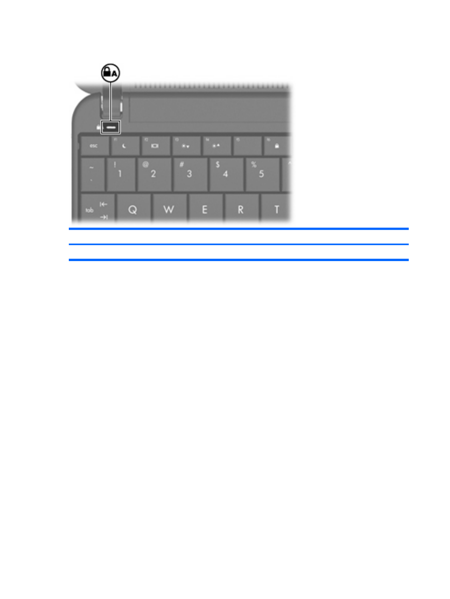
Light
Component Description
Caps lock light On: Caps lock is on.
6 Chapter 2 External component identification
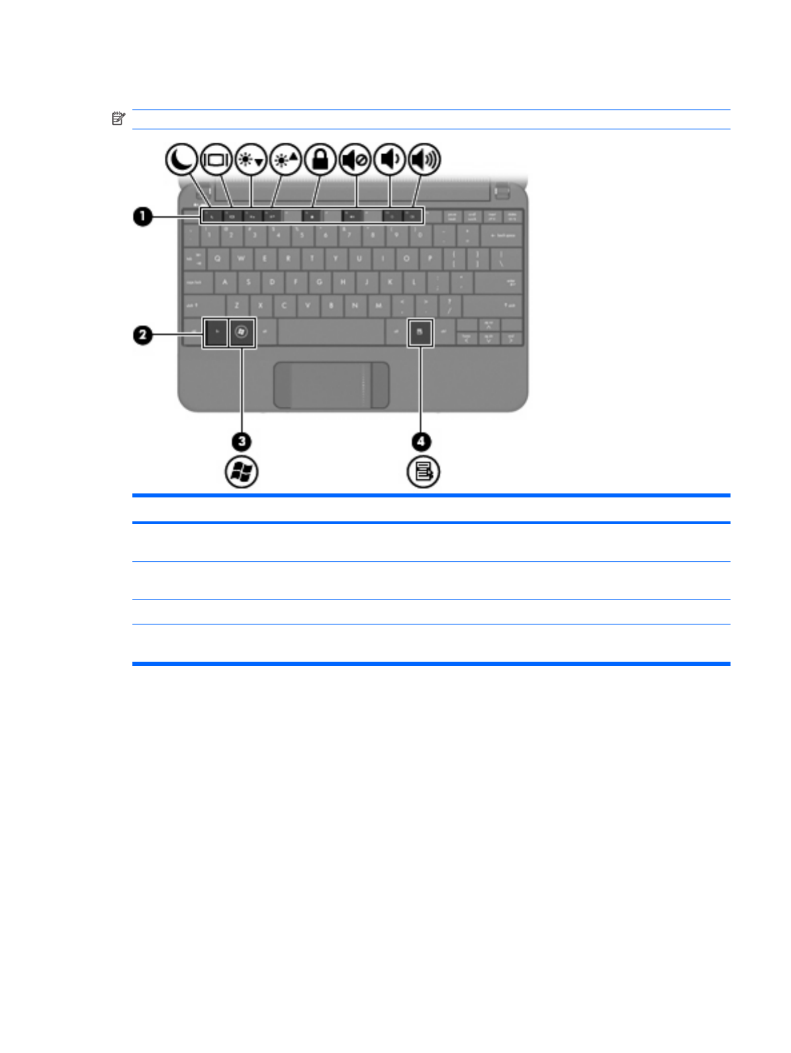
Keys
NOTE: Refer to the illustration that most closely matches your computer.
Component Description
(1) Function keys Execute frequently used system functions when
pressed in combination with the fn key.
(2) fn key Executes frequently used system functions when
pressed in combination with a function key.
(3) Windows® logo key Displays the Windows Start menu.
(4) Windows applications key Displays a shortcut menu for items beneath the
pointer.
Top components 7

Component Description
(1) Function keys Execute frequently used system functions when pressed in
combination with the fn key.
(2) fn key Executes frequently used system functions when pressed in
combination with a function key.
(3) Home key Returns to the Home Screen.
(4) Program Switcher key Displays the Start New Program button from anywhere on the
device.
8 Chapter 2 External component identification
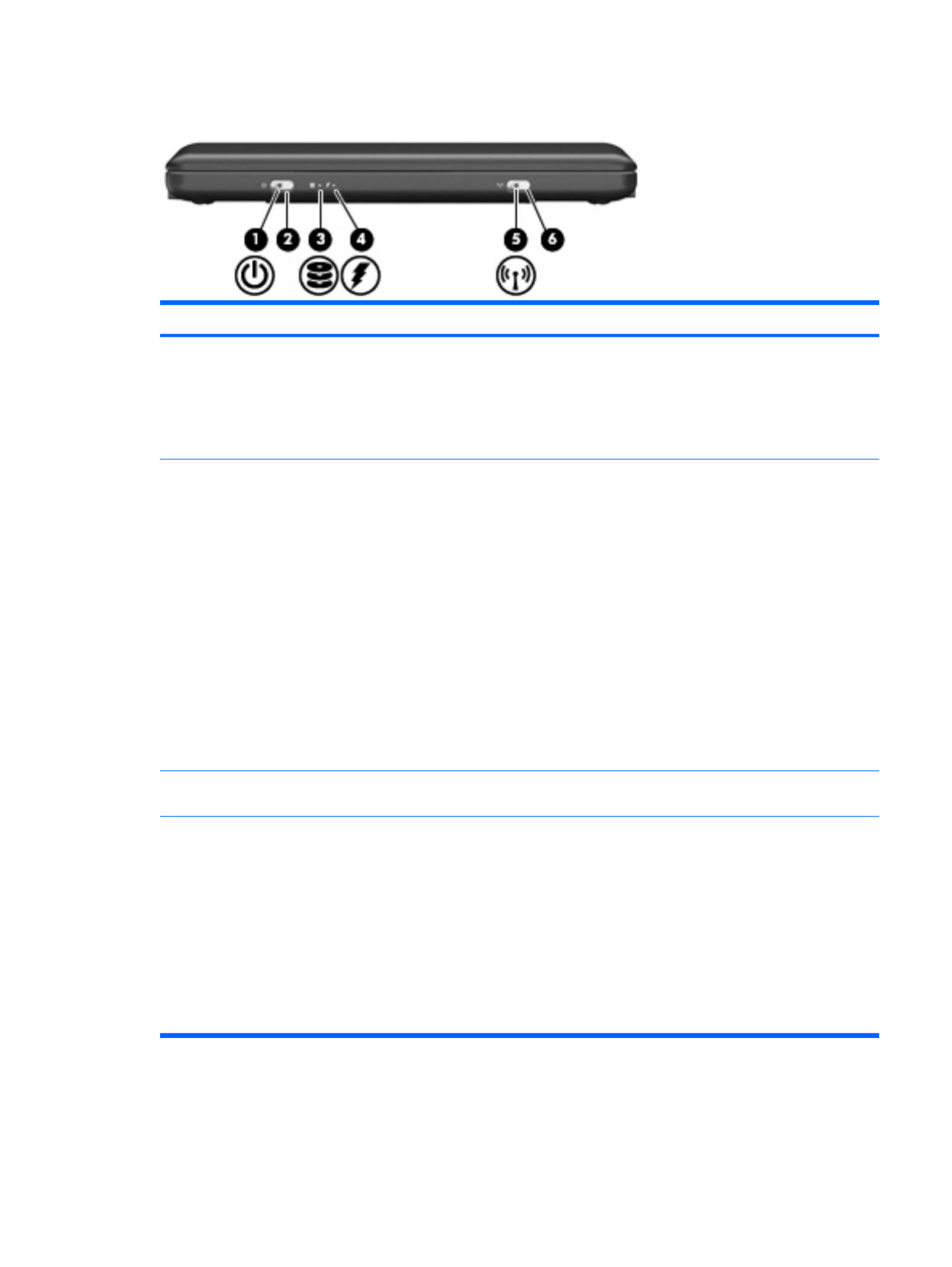
Front components
Component Description
(1) Power light ●On: The device is on.
●Blinking: The device is in the Sleep state
(Windows Vista) or Standby (Windows XP or
Mobile Mi).
●Off: The device is off or in Hibernation.
(2) Power switch ●When the device is off, slide the switch to turn
on the device.
●When the device is on, briefly slide the switch to
initiate Hibernation.
●When the device is in the Sleep state (Windows
Vista) or Standby (Windows XP or Mobile Mi),
briefly slide the switch to exit the Sleep state
(Windows Vista) or Standby (Windows XP or
Mobile Mi).
●When the device is in Hibernation, briefly slide
the switch to exit Hibernation.
If the device has stopped responding and operating
system shutdown procedures are ineffective, slide
and hold the power switch for at least 5 seconds to
turn off the device.
(3) Drive light Blinking: The hard drive or flash drive is being
accessed.
(4) Battery light ●On: A battery is charging.
●Blinking: A battery that is the available only
power source has reached a low battery level.
When the battery reaches a critical battery level,
the battery light begins blinking rapidly.
●Off: If the device is plugged into an external
power source, the light turns off when all
batteries in the device are fully charged. If the
device is not plugged into an external power
source, the light stays off until the battery
reaches a low battery level.
Front components 9
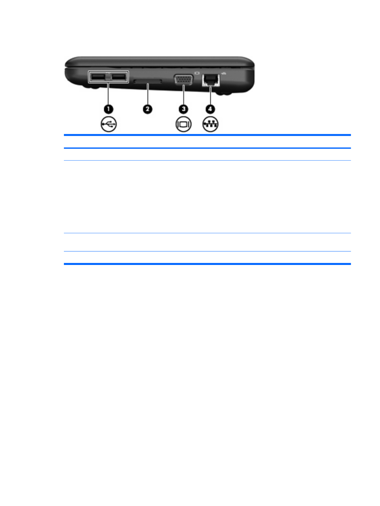
Right-side components
Component Description
(1) USB ports (2) Connect optional USB devices.
(2) Digital Media Slot (consumer models) or Media Card
Reader (commercial models)
Supports the following optional digital card formats:
●Memory Stick (MS)
●Memory Stick Pro (MSP)
●MultiMediaCard (MMC)
●Secure Digital (SD) Memory Card
●xD-Picture Card
(3) External monitor port Connects an optional external display, such as a
monitor or projector, to the device.
(4) RJ-45 (network) jack Connects a network cable.
Right-side components 11
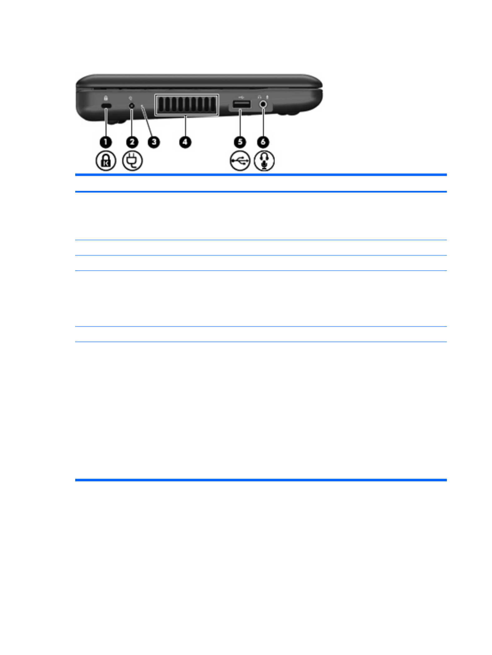
Left-side components
Component Description
(1) Security cable slot Attaches an optional security cable to the device.
NOTE: The security cable is designed to act as a
deterrent, but it may not prevent the device from being
mishandled or stolen.
(2) Power connector Connects an AC adapter.
(3) AC adapter light Indicates AC power connection.
(4) Vent Enables airflow to cool internal components.
NOTE: The device fan starts up automatically to
cool internal components and prevent overheating. It
is normal for the internal fan to cycle on and off during
routine operation.
(5) USB port Connects an optional USB device.
(6) Audio-out (headphone) jack/Audio-in (microphone)
jack
Produces sound when connected to optional powered
stereo speakers, headphones, earbuds, a headset, or
television audio. Also connects an optional headset
microphone.
WARNING! To reduce the risk of personal injury,
adjust the volume before putting on headphones,
earbuds, or a headset. For additional safety
information, refer to the Regulatory, Safety and
Environmental Notices.
NOTE: When an audio component is connected to
the jack, the device speakers are disabled.
The audio component cable must have a 4-conductor
connector.
12 Chapter 2 External component identification

Display components
Component Description
(1) Speakers (2) Produce sound.
(2) Internal display switch Turns off the display if the display is closed while the
power is on.
NOTE: The display switch is not visible from the
outside of the device.
(3) Webcam Captures still photographs and videos.
NOTE: To capture videos, you need to install additional
webcam software.
(4) Webcam light On: The webcam is in use.
(5) Internal microphone Records sound.
Display components 13

Bottom components
Component Description
(1) Battery bay Holds the battery.
(2) Battery release latches (2) Release the battery from the battery bay.
(3) Vent Enables airflow to cool internal components.
NOTE: The device fan starts up automatically to cool
internal components and prevent overheating. It is normal
for the internal fan to cycle on and off during routine
operation.
(4) Memory module compartment Contains the memory module slot.
14 Chapter 2 External component identification

Wireless antennas
Component Description
(1) WWAN antennas (2) (select models only)* Send and receive wireless signals to communicate with wireless
wide-area networks (WWANs).
NOTE: This option is not available on computers with Mobile Mi
installed.
(2) WLAN antennas (2)* to communicate with wirelessSend and receive wireless signals
local area networks (WLANs).
*The antennas are not visible from the outside of the device. For optimal transmission, keep the areas immediately around the
antennas free from obstructions.
To see wireless regulatory notices, refer to the section of the Regulatory, Safety and Environmental
Notices that applies to your country or region.
Wireless antennas 15

3 Illustrated parts catalog
Service tag
When ordering parts or requesting information, provide the computer serial number and model
description provided on the service tag:
(1) Product name: This is the product name affixed to the front of the device.
(2) Serial number (s/n): This is an alphanumeric identifier that is unique to each product.
(3) Part number/Product number (p/n): This number provides specific information about the product's
hardware components. The part number helps a service technician to determine what components and
parts are needed.
(4) Model description: This is the alphanumeric identifier used to locate documents, drivers, and support
for the device.
(5) Warranty period: This number describes the duration of the warranty period for the device.
16 Chapter 3 Illustrated parts catalog

Device major components
Item Description Spare part number
(1) Display assembly (includes 1 webcam, 1 microphone, 1 speaker box, and 2 WLAN antenna
transceivers/cables; WWAN is optional)
See Display assembly components on page 21 for a comprehensive list of display assembly
spare parts.
For use with HP models only
●10.1-inch, high-definition, AntiGlare Display Assembly (Includes WWAN) 572407-001
●10.1-inch, high-definition, AntiGlare Display Assembly 572406-001
Device major components 17

Item Description Spare part number
●10.1-inch, standard-definition, AntiGlare Display Assembly (includes WWAN) 571414-001
●10.1-inch, standard-definition, AntiGlare Display Assembly 537646-001
For use with Compaq models only
●10.1-inch, high-definition, AntiGlare Display Assembly 572414-001
●10.1-inch, standard-definition, AntiGlare Display Assembly (includes WWAN) 571417-001
●10.1-inch, standard-definition, AntiGlare Display Assembly 537643-001
(2) Keyboard
For use only on models with Windows operating system installed
●For use only in Brazil 535689-201
●For use only in the Czech Republic 535689-221
●For use only in Europe 535689-A41
●For use only in France 535689-051
●For use only in French Canada 535689-121
●For use only in Finland, Norway, and Sweden 535689-DH1
●For use only in Germany 535689-041
●For use only in Greece 535689-151
●For use only in Hungary 535689-211
●For use on international models 535689-B31
●For use only in Israel 535689-BB1
●For use only in Italy 535689-061
●For use only in Japan 535689-291
●For use only in Latin America 535689-161
●For use only in Portugal 535689-131
●For use only in Russia 535689-251
●For use only in Saudi Arabia 535689-171
●For use only South Korea 535689-AD1
●For use only in Spain 535689-071
●For use only in Switzerland 535689-111
●For use only in Taiwan 535689-AB1
●For use only in Thailand 535689-281
●For use only in Turkey 535689-141
●For use only in the United Kingdom 535689-031
●For use only in the United States 535689-001
For use only on models with Mobile Mi installed
18 Chapter 3 Illustrated parts catalog

Item Description Spare part number
●For use in Afghanistan, Albania, Algeria, Andorra, Angola, Antigua and Barbuda,
Argentina, Armenia, Aruba, Australia, Austria, Azerbaijan, the Bahamas, Bahrain,
Bangladesh, Barbados, Belarus, Belgium, Belize, Benin, Bermuda, Bhutan, Bolivia,
Bosnia and Herzegovina, Botswana, Brazil, the British Virgin Islands, Brunei, Bulgaria,
Burkina Faso, Burundi, Cameroon, Cape Verde, the Central African Republic, Chad,
Chile, the People's Republic of China, Colombia, Comoros, the Congo, Costa Rica,
Croatia, Cyprus, the Czech Republic, Denmark, Djibouti, Dominica,
the Dominican Republic, East Timor, Ecuador, Egypt, El Salvador, Equatorial Guinea,
Eritrea, Estonia, Ethiopia, Fiji, Finland, France, French Guiana, Gabon, Gambia, Georgia,
Germany, Ghana, Gibraltar, Greece, Grenada, Guadeloupe, Guatemala, Guinea,
Guinea-Bissau, Guyana, Haiti, Honduras, Hong Kong, Hungary, Iceland, India, Ireland,
Israel, Italy, the Ivory Coast, Jamaica, Jordan, Kazakhstan, Kenya, Kiribati, Kyrgyzstan,
Laos, Latvia, Lebanon, Lesotho, Liberia, Liechtenstein, Lithuania, Luxembourg,
Macedonia, Madagascar, Malawi, Malaysia, the Maldives, Mali, Malta,
the Marshall Islands, Martinique, Mauritania, Mauritius, Mexico, Micronesia, Monaco,
Mongolia, Montenegro, Morocco, Mozambique, Namibia, Nauru, Nepal,
the Nether Antilles, the Netherlands, New Zealand, Nicaragua, Niger, Nigeria, Norway,
Oman, Pakistan, Palau, Panama, Papua New Guinea, Paraguay, Peru, the Philippines,
Poland, Portugal, the Republic of Moldova, Romania, Russia, Rwanda, Samoa,
San Marino, Sao Tome and Principe, Saudi Arabia, Senegal, Serbia, the Seychelles,
Sierra Leone, Singapore, Slovakia, Slovenia, the Solomon Islands, Somalia,
South Africa, South Korea, Spain, Sri Lanka, St. Kitts and Nevis, St. Lucia,
St. Vincent and the Grenadines, Suriname, Swaziland, Sweden, Switzerland, Taiwan,
Tajikistan, Tanzania, Togo, Tonga, Trinidad and Tobago, Tunisia, Turkey, Turkmenistan,
Tuvalu, Uganda, Ukraine, the United Arab Emirates, the United Kingdom, Uruguay,
Uzbekistan, Vanuatu, Venezuela, Vietnam, Yemen, Zaire, Zambia, and Zimbabwe
504593-004
(11) WWAN module
NOTE: Not available for computers with Mobile Mi installed.
HP un2400 Mobile Broadband Module (select models only) 483377-002
HP un2400 Mobile Broadband Module for use only with Verizon Wireless (select models only) 483377-003
WWAN module for use only in China 571888-001
(12) RTC battery 537616-001
(13) System board (includes processor and replacement thermal material)
Includes Intel Atom N280 1.66-GHz processor, 512-KB Level 2 cache, 533-MHz front-side bus
(FSB)
571370-001
Includes Intel Atom N270 1.6-GHz processor, 512-KB Level 2 cache, 533-MHz front-side bus
(FSB)
537662-001
(14) Memory module (PC2-5300, 533-MHz, DDR2)
512-MB (for use in HP Mini 110 and Compaq Mini 110 models only) 537663-001
1024-MB 537664-001
2048-MB (for use in HP Mini 1101 NoteBook PC, and HP Mini 110 with Mobile Mi installed
only)
537665-001
(15) Base enclosure (includes 4 rubber feet) 537611-001
(16) Battery
6-cell lithium-polymer (Li-Pol) battery (2.55-Ah, 55-Wh) 537627-001
3-cell lithium-polymer (Li-Pol) battery (2.55-Ah, 28-Wh) 537626-001
20 Chapter 3 Illustrated parts catalog

Display assembly components
Item Description Spare part number
(1) Hinge covers 537617-001
(2) Display bezel
For use with HP Mini 1101 NoteBook PC, and HP Mini 110 only 537650-001
For use with Compaq Mini 110 only 537644-001
(3) Display Hinge Kit
(Includes left and right display panel hinges)
537658-001
(4) Speaker assembly (includes left and right cables) 537621-001
(5) Display panel
10.1-inch high-definition AntiGlare 572405-001
10.1-inch standard-definition AntiGlare 537656-001
(6) Webcam module 537660-001
Display Cable Kit (Not illustrated, includes microphone assembly display cable, webcam
cable, and WLAN antennas)
537657-001
(7a) Display panel cable
(7b) WLAN antennas
Display assembly components 21

Item Description Spare part number
(7c) Microphone assembly
(8) WWAN antennas (not available on computers with Mobile Mi installed.) 537655-001
(9) Display enclosure (includes logo)
For use with the HP Mini 1101 Notebook PC, and HP Mini 110 537651-001
For use with the Compaq Mini 110 537645-001
Display Screw Kit (not illustrated) 538510-001
22 Chapter 3 Illustrated parts catalog

Mass storage devices
NOTE: Each hard drive spare part kit and solid-state drive spare part kit includes a cable and bracket.
Item Description Spare part number
(1) Hard drive (select models only)
250-GB, 5400-RPM 537635-001
160-GB, 5400-RPM 537634-001
Hard Drive Hardware Kit (not illustrated) 537641-001
(2) Solid-state drive
64-GB 537640-001
32-GB 537639-001
16-GB 537638-001
8-GB 537637-001
Solid–state Drive Hardware Kit (not illustrated) 537642-001
Mass storage devices 23

Miscellaneous parts
Description Spare part number
30-W UMA AC adapter 496813-001
Bluetooth® adapter 574670-001
Power cords
For use in Argentina 490371-D01
For use in Australia 490371-011
For use in Brazil 490371-201
For use in China 490371-AA1
For use in Denmark 490371-081
For use in Europe 490371-021
For use in India 490371-D61
For use in Israel 490371-BB1
For use in Italy 490371-061
For use in Japan 490371-291
For use in North America 490371-001
For use in Singapore and the United Kingdom 490371-031
For use in South Africa 490371-AR1
For use in South Korea 490371-AD1
For use in Switzerland 490371-111
For use in Taiwan 490371-AB1
Rubber Kit (contains 4 device feet) 537618-001
Screw Kit 537620-001
24 Chapter 3 Illustrated parts catalog

Spare part
number
Description
535689-001 Keyboard for use only in the United States on models with Windows operating system installed
535689-031 Keyboard for use only in the United Kingdom on models with Windows operating system installed
535689-041 Keyboard for use only in Germany on models with Windows operating system installed
535689-051 Keyboard for use only in France on models with Windows operating system installed
535689-061 Keyboard for use only in Italy on models with Windows operating system installed
535689-071 Keyboard for use only in Spain on models with Windows operating system installed
535689-121 Keyboard for use only in French Canada on models with Windows operating system installed
535689-131 Keyboard for use only in Portugal on models with Windows operating system installed
535689-141 Keyboard for use only in Turkey on models with Windows operating system installed
535689-161 Keyboard for use only in Latin America on models with Windows operating system installed
535689-171 Keyboard for use only in Saudi Arabia on models with Windows operating system installed
535689-201 Keyboard for use only in Brazil on models with Windows operating system installed
535689-211 Keyboard for use only in Hungary on models with Windows operating system installed
535689-221 Keyboard for use only in the Czech Republic on models with Windows operating system installed
535689-251 Keyboard for use only in Russia on models with Windows operating system installed
535689-281 Keyboard for use only in Thailand on models with Windows operating system installed
535689-291 Keyboard for use only in Japan on models with Windows operating system installed
535689-A41 Keyboard for use only in Europe on models with Windows operating system installed
535689-AB1 Keyboard for use only in Taiwan on models with Windows operating system installed
535689-AD1 Keyboard for use only in South Korea on models with Windows operating system installed
535689-B31 Keyboard for use only in international models with Windows operating system installed
535689-BB1 Keyboard for use only in Israel on models with Windows operating system installed
535689-DH1 Keyboard for use only in Finland, Norway and Sweden on models with Windows operating system installed
535690-001 Keyboard for use only in the United States on models with Mobile Mi installed
535690-121 Keyboard for use only in French Canada on models with Mobile Mi installed
535690-161 Keyboard for use only in Latin America on models with Mobile Mi installed
535690-201 Keyboard for use only in Brazil on models with Mobile Mi installed
535690-281 Keyboard for use only in Thailand on models with Mobile Mi installed
535690-291 Keyboard for use only in Japan on models with Mobile Mi installed
535690-AB1 Keyboard for use only in Taiwan on models with Mobile Mi installed
535690-AD1 Keyboard for use only in South Korea on models with Mobile Mi installed
537611-001 Base enclosure (includes 4 rubber feet)
537612-001 Plastics/actuator kit (includes power switch and wireless switch actuators, memory module compartment
cover, and bezel for Digital Media Slot (consumer models) or Media Card Reader (commercial models)
26 Chapter 3 Illustrated parts catalog

Spare part
number
Description
537613-001 Fan
537614-001 USB/audio board (includes cable)
537615-001 Power/battery pass-through board
537616-001 RTC battery
537617-001 Display assembly hinge covers
537618-001 Rubber Kit (contains 4 device feet)
537619-001 Heat sink assembly (includes replacement thermal material)
537620-001 Screw Kit
537621-001 Speaker assembly (includes left and right cables)
537622-001 Top cover (includes TouchPad)
537626-001 3-cell lithium-polymer (Li-Pol) battery (2.55-Ah, 28-Wh)
537627-001 6-cell lithium-polymer (Li-Pol) battery (2.55-Ah, 55-Wh)
537634-001 160-GB hard drive, 5400-RPM
537635-001 250-GB hard drive, 5400-RPM
537637-001 8-GB solid-state drive
537638-001 16-GB solid-state drive
537639-001 32-GB solid-state drive
537640-001 64-GB solid-state drive
537641-001 Hard Drive Hardware Kit
537642-001 Solid-state Drive Hardware Kit
537643-001 10.1-inch, standard-definition, AntiGlare Display Assembly for use with Compaq standard models only
537644-001 Display bezel for use with Compaq Mini 110 only
537645-001 Display enclosure (includes logo) for use with the Compaq Mini 110
537646-001 10.1-inch, standard-definition, AntiGlare Display Assembly for use with HP models only
537650-001 Display bezel for use with HP Mini 1101 NoteBook PC, and HP Mini 110 only
537651-001 Display enclosure (includes logo) for use with the HP Mini 1101 Notebook PC, and HP Mini 110
537655-001 WWAN antennas
537656-001 10.1-inch standard-definition AntiGlare display panel
537657-001 Display Cable Kit (includes micr ebcam cable, and WLAN antennas)ophone assembly display cable, w
537658-001 Display Hinge Kit (Includes left and right display panel hinges)
537660-001 Webcam module
537662-001 System board (Includes Intel Atom N270 1.6-GHz processor, 512-KB Level 2 cache, 533-MHz front-side bus
(FSB), and replacement thermal material)
Sequential part number listing 27

Spare part
number
Description
537663-001 512-MB memory module (PC2-5300, 533-MHz, DDR2 for use in HP Mini 110 and Compaq Mini 110 models
only)
537664-001 1024-MB memory module (PC2-5300, 533-MHz, DDR2 for use in HP Mini 110 and Compaq Mini 110 models
only)
537665-001 2048-MB memory module (PC2-5300, 533-MHz, DDR2 for use in HP Mini 110 and Compaq Mini 110 models
only)
538510-001 Display Screw Kit (not illustrated)
571370-001 System board (Includes Intel Atom N280 1.66-GHz processor, 512-KB Level 2 cache, 533-MHz front-side bus
(FSB), and replacement thermal material)
571414-001 10.1-inch, standard-definition, AntiGlare Display Assembly (includes WWAN) for use with HP models only
571417-001 10.1-inch, standard-definition, AntiGlare Display Assembly (includes WWAN) for use with Compaq standard
models only
571888-001 WWAN module, for use only in China
572405-001 10.1-inch high-definition AntiGlare display panel
572406-001 10.1-inch, high-definition, AntiGlare Display Assembly for use with HP models only
572407-001 10.1-inch, high-definition, AntiGlare Display Assembly (Includes WWAN) for use with HP models only
572414-001 10.1-inch, high-definition, AntiGlare Display Assembly for use with Compaq standard models only
574670-001 Bluetooth adapter
28 Chapter 3 Illustrated parts catalog

4 Removal and replacement procedures
Preliminary replacement requirements
Tools required
You will need the following tools to complete the removal and replacement procedures:
●Flat-bladed screwdriver
●Magnetic screwdriver
●Phillips P0 and P1 screwdrivers
Service considerations
The following sections include some of the considerations that you must keep in mind during
disassembly and assembly procedures.
NOTE: As you remove each subassembly from the device, place the subassembly (and all
accompanying screws) away from the work area to prevent damage.
Plastic parts
CAUTION: Using excessive force during disassembly and reassembly can damage plastic parts. Use
care when handling the plastic parts. Apply pressure only at the points designated in the maintenance
instructions.
Cables and connectors
CAUTION: When servicing the device, be sure that cables are placed in their proper locations during
the reassembly process. Improper cable placement can damage the device.
Cables must be handled with extreme care to avoid damage. Apply only the tension required to unseat
or seat the cables during removal and insertion. Handle cables by the connector whenever possible. In
all cases, avoid bending, twisting, or tearing cables. Be sure that cables are routed in such a way that
they cannot be caught or snagged by parts being removed or replaced. Handle flex cables with extreme
care; these cables tear easily.
Preliminary replacement requirements 29

Drive handling
CAUTION: Drives are fragile components that must be handled with care. To prevent damage to the
device, damage to a drive, or loss of information, observe these precautions:
Before removing or inserting a hard drive, shut down the device. If you are unsure whether the device
is off or in Hibernation, turn the device on, and then shut it down through the operating system.
Before handling a drive, be sure that you are discharged of static electricity. While handling a drive,
avoid touching the connector.
Handle drives on surfaces covered with at least one inch of shock-proof foam.
Avoid dropping drives from any height onto any surface.
After removing a hard drive, an optical drive, or a diskette drive, place it in a static-proof bag.
Avoid exposing a hard drive to products that have magnetic fields, such as monitors or speakers.
Avoid exposing a drive to temperature extremes or liquids.
If a drive must be mailed, place the drive in a bubble pack mailer or other suitable form of protective
packaging and label the package “FRAGILE.”
30 Chapter 4 Removal and replacement procedures

Grounding guidelines
Electrostatic discharge damage
Electronic components are sensitive to electrostatic discharge (ESD). Circuitry design and structure
determine the degree of sensitivity. Networks built into many integrated circuits provide some protection,
but in many cases, ESD contains enough power to alter device parameters or melt silicon junctions.
A discharge of static electricity from a finger or other conductor can destroy static-sensitive devices or
microcircuitry. Even if the spark is neither felt nor heard, damage may have occurred.
An electronic device exposed to ESD may not be affected at all and can work perfectly throughout a
normal cycle. Or the device may function normally for a while, then degrade in the internal layers,
reducing its life expectancy.
CAUTION: To prevent damage to the device when you are removing or installing internal components,
observe these precautions:
Keep components in their electrostatic-safe containers until you are ready to install them.
Use nonmagnetic tools.
Before touching an electronic component, discharge static electricity by using the guidelines described
in this section.
Avoid touching pins, leads, and circuitry. Handle electronic components as little as possible.
If you remove a component, place it in an electrostatic-safe container.
The following table shows how humidity affects the electrostatic voltage levels generated by different
activities.
CAUTION: A product can be degraded by as little as 700 V.
Typical electrostatic voltage levels
Relative humidity
Event 10% 40% 55%
Walking across carpet 35,000 V 15,000 V 7,500 V
Walking across vinyl floor 12,000 V 5,000 V 3,000 V
Motions of bench worker 6,000 V 800 V 400 V
Removing DIPS from plastic tube 2,000 V 700 V 400 V
Removing DIPS from vinyl tray 11,500 V 4,000 V 2,000 V
Removing DIPS from Styrofoam 14,500 V 5,000 V 3,500 V
Removing bubble pack from PCB 26,500 V 20,000 V 7,000 V
Packing PCBs in foam-lined box 21,000 V 11,000 V 5,000 V
Preliminary replacement requirements 31

Packaging and transporting guidelines
Follow these grounding guidelines when packaging and transporting equipment:
●To avoid hand contact, transport products in static-safe tubes, bags, or boxes.
●Protect ESD-sensitive parts and assemblies with conductive or approved containers or packaging.
●Keep ESD-sensitive parts in their containers until the parts arrive at static-free workstations.
●Place items on a grounded surface before removing items from their containers.
●Always be properly grounded when touching a component or assembly.
●Store reusable ESD-sensitive parts from assemblies in protective packaging or nonconductive
foam.
●Use transporters and conveyors made of antistatic belts and roller bushings. Be sure that
mechanized equipment used for moving materials is wired to ground and that proper materials are
selected to avoid static charging. When grounding is not possible, use an ionizer to dissipate
electric charges.
Workstation guidelines
Follow these grounding workstation guidelines:
●Cover the workstation with approved static-shielding material.
●Use a wrist strap connected to a properly grounded work surface and use properly grounded tools
and equipment.
●Use conductive field service tools, such as cutters, screwdrivers, and vacuums.
●When fixtures must directly contact dissipative surfaces, use fixtures made only of static-safe
materials.
●Keep the work area free of nonconductive materials, such as ordinary plastic assembly aids and
Styrofoam.
●Handle ESD-sensitive components, parts, and assemblies by the case or PCM laminate. Handle
these items only at static-free workstations.
●Avoid contact with pins, leads, or circuitry.
●Turn off power and input signals before inserting or removing connectors or test equipment.
32 Chapter 4 Removal and replacement procedures

Component replacement procedures
This chapter provides removal and replacement procedures.
There are as many as 65 screws, in 9 different sizes, that must be removed, replaced, or loosened when
servicing the device. Make special note of each screw size and location during removal and replacement.
Service tag
When ordering parts or requesting information, provide the computer serial number and model
description provided on the service tag:
(1) Product name: This is the product name affixed to the front of the device.
(2) Serial number (s/n): This is an alphanumeric identifier that is unique to each product.
(3) Part number/Product number (p/n): This number provides specific information about the product's
hardware components. The part number helps a service technician to determine what components and
parts are needed.
(4) Model description: This is the alphanumeric identifier used to locate documents, drivers, and support
for the device.
(5) Warranty period: This number describes the duration of the warranty period for the device.
34 Chapter 4 Removal and replacement procedures

Device feet
The device feet are adhesive-backed rubber pads, tethered to the base enclosure.
Description Spare part number
Rubber Kit 537618-001
Component replacement procedures 35

Battery
Description Spare part number
6-cell lithium-polymer (Li-Pol) battery (2.55-Ah, 55-Wh) 537627-001
3-cell lithium-polymer (Li-Pol) battery (2.55-Ah, 28-Wh) 537626-001
Before disassembling the device, follow these steps:
1. Shut down the device. If you are unsure whether the device is off or in Hibernation, turn the device
on, and then shut it down through the operating system.
2. Disconnect all external devices connected to the device.
3. Disconnect the power from the device by first unplugging the power cord from the AC outlet and
then unplugging the AC adapter from the device.
Remove the battery:
1. Turn the device upside-down on a flat surface, with the battery bay toward you.
2. Slide the battery release latches (1) to release the battery.
3. Remove the battery (2).
Reverse this procedure to install a battery.
36 Chapter 4 Removal and replacement procedures

SIM
NOTE: This section applies only to device models with WWAN capability.
NOTE: If there is a SIM inserted in the SIM slot, it must be removed before disassembling the
computer. Be sure that the SIM is reinserted in the SIM slot after reassembling the computer.
Before removing the SIM, follow these steps:
1. Shut down the computer. If you are unsure whether the computer is off or in Hibernation, turn the
computer on, and then shut it down through the operating system.
2. Disconnect all external devices connected to the computer.
3. Disconnect the power from the computer by first unplugging the power cord from the AC outlet and
then unplugging the AC adapter from the computer.
4. Remove the battery (see Battery on page 36).
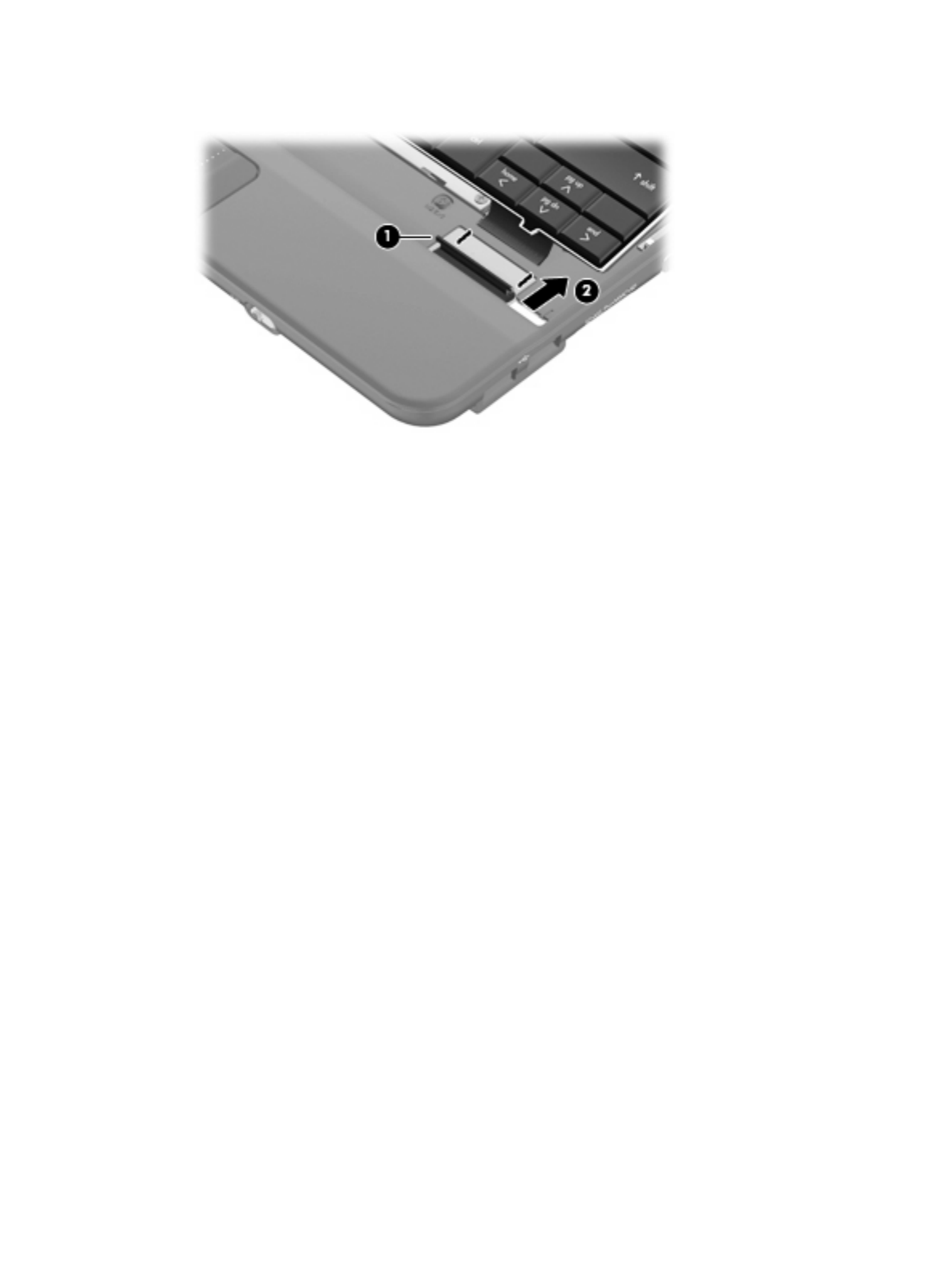
Remove the SIM:
1. Press in on the SIM (1). (The module is partially ejected from the SIM slot.)
2. Remove the SIM (2) from the SIM slot.
Reverse this procedure to insert the SIM.
Component replacement procedures 37

Memory module
Description Spare part number
Memory module (PC2-5300, 533-MHz, DDR2)
512-MB (for use in HP Mini 110 and Compaq Mini 110 only) 537663-001
1024-MB 537664-001
2048-MB (for use in HP Mini 1101 NoteBook PC, and HP Mini 110 with Mobile Mi installed only) 537665-001
Before removing the memory module, follow these steps:
1. Shut down the device. If you are unsure whether the device is off or in Hibernation, turn the device
on, and then shut it down through the operating system.
2. Disconnect all external devices connected to the device.
3. Disconnect the power from the device by first unplugging the power cord from the AC outlet and
then unplugging the AC adapter from the device.
4. Remove the battery (see Battery on page 36).
5. If your device has WWAN capability, remove the SIM (see SIM on page 37.
Remove the memory module:
1. Loosen the 2 Phillips 2.0×3.0 captive screws (1) that secure the memory module compartment
cover to the computer.
2. Swing the cover up and away from the inside of the computer (2), and then remove the cover (3).
3. Spread the retaining tabs (1) on each side of the memory module slot to release the memory
module. (The edge of the module opposite the slot rises away from the device.)
38 Chapter 4 Removal and replacement procedures

4. Remove the memory module (2) by pulling the module away from the slot at an angle.
NOTE: Memory modules are designed with a notch (3) to prevent incorrect insertion into the
memory module slot.
Reverse this procedure to install a memory module.
Component replacement procedures 39

Keyboard
Description Spare part number
For use only on models with Windows operating system installed
●For use only in Brazil 535689-201
●For use only in the Czech Republic 535689-221
●For use only in Europe 535689-021
●For use only in Finland, Norway, and Sweden 535689-DH1
●For use only in France 535689-051
●For use only in French Canada 535689-121
●For use only in Germany 535689-041
●For use only in Greece 535689-151
●For use only in Hungary 535689-211
●For use on international models 535689-B31
●For use only in Israel 535689-BB1
●For use only in Italy 535689-061
●For use only in Japan 535689-291
●For use only in Latin America 535689-161
●For use only in Portugal 535689-131
●For use only in Russia 535689-251
●For use only in Saudi Arabia 535689-171
●For use only South Korea 535689-AD1
●For use only in Spain 535689-071
●For use only in Switzerland 535689-111
●For use only in Taiwan 535689-AB1
●For use only in Thailand 535689-281
●For use only in Turkey 535689-141
●For use only in the United Kingdom 535689-031
●For use only in the United States 535689-001
For use only on models with Mobile Mi installed
●For use only in Brazil 535690-201
●For use only in French Canada 535690-121
●For use only in Japan 535690-291
●For use only in Latin America 535690-161
●For use only in South Korea 535690-AD1
●For use only in Taiwan 535690-AB1
40 Chapter 4 Removal and replacement procedures

Description Spare part number
●For use only in Thailand 535690-281
●For use only in the United States 535690-001
Before removing the keyboard, follow these steps:
1. Shut down the device. If you are unsure whether the device is off or in Hibernation, turn the device
on, and then shut it down through the operating system.
2. Disconnect all external devices connected to the device.
3. Disconnect the power from the device by first unplugging the power cord from the AC outlet and
then unplugging the AC adapter from the device.
4. Remove the battery (see Battery on page 36).
5. If your device has WWAN capability, remove the SIM (see SIM on page 37.
Remove the keyboard:
1. Remove the 3 Phillips SP2.0×3.0 screws that secure the keyboard to the device.
2. Turn the device right-side up, and then open the display as far as possible.
3. Turn the device upside down, and locate the keyboard release access on the bottom of the
computer, inside the battery bay.
Component replacement procedures 41

4. Insert a flexible tool into the opening, and then press inward to release the keyboard.
5. Turn the device right-side up, and then lift up on the top and left edges (1) of the keyboard until the
keyboard releases completely.
6. Slide the keyboard back until its top edge rests on the display assembly (2).
7. Release the zero insertion force (ZIF) connector (1) to which the keyboard cable is attached.
42 Chapter 4 Removal and replacement procedures
8. Disconnect the cable (2), and then remove the keyboard.
9. Remove the keyboard.
Reverse this procedure to install the keyboard.
Component replacement procedures 43

RTC battery
Description Spare part number
RTC battery 537616-001
Before removing the real-time clock (RTC) battery, follow these steps:
1. Shut down the device. If you are unsure whether the device is off or in Hibernation, turn the device
on, and then shut it down through the operating system.
2. Disconnect all external devices connected to the device.
3. Disconnect the power from the device by first unplugging the power cord from the AC outlet and
then unplugging the AC adapter from the device.
4. Remove the battery (see Battery on page 36).
5. If your device has WWAN capability, remove the SIM (see SIM on page 37.
6. Remove the Keyboard (see Keyboard on page 40)
Remove the RTC battery:
1. Disconnect the RTC battery cable (1) from the system board.
2. Detach the RTC battery (2) from the system board.
NOTE: The RTC battery is attached to the system board with double-sided tape.
Reverse this procedure to install the RTC battery.
44 Chapter 4 Removal and replacement procedures

Mass storage devices
NOTE: Each hard drive spare part kit and solid-state drive spare part kit includes a cable and bracket.
Description Spare part number
Hard drive (select models only)
250-GB, 5400-RPM 537635-001
160-GB, 5400-RPM 537634-001
Hard Drive Hardware Kit 537641-001
Solid-state drive
64-GB 537640-001
32-GB 537639-001
16-GB 537638-001
8-GB 537637-001
Solid–state Drive Hardware Kit 537642-001
Before removing the hard drive or solid-state drive, follow these steps:
1. Shut down the device. If you are unsure whether the device is off or in Hibernation, turn the device
on, and then shut it down through the operating system.
2. Disconnect all external devices connected to the device.
3. Disconnect the power from the device by first unplugging the power cord from the AC outlet and
then unplugging the AC adapter from the device.
4. Remove the battery (see Battery on page 36).
5. If your device has WWAN capability, remove the SIM (see SIM on page 37.
6. Remove the keyboard (see Keyboard on page 40).
To remove the mass storage assembly:
1. Loosen the Phillips SP2.5×10.0 captive screw (1), and remove the two Phillips PM2.0×5.0
screws (2) that secure the assembly to the device.
Component replacement procedures 45

2. Use the Mylar tab to slide the assembly to the left (3) to disconnect it, and remove the
assembly (4).
Continue with one of the following sections for hard drive or solid-state drive replacement.
Hard drive
1. Remove the 4 Phillips SP3.0×4.0 screws (1) that secure the hard drive bracket to the hard drive.
2. Using the Mylar tab, lift the bracket (2) away from the hard drive.
Reverse this procedure to install a hard drive.
Solid-state drive
To remove the solid-state drive:
1. Remove the 4 Phillips SP2.0×3.0 screws (1) that secure the solid-state drive bracket to the solid-
state drive.
46 Chapter 4 Removal and replacement procedures
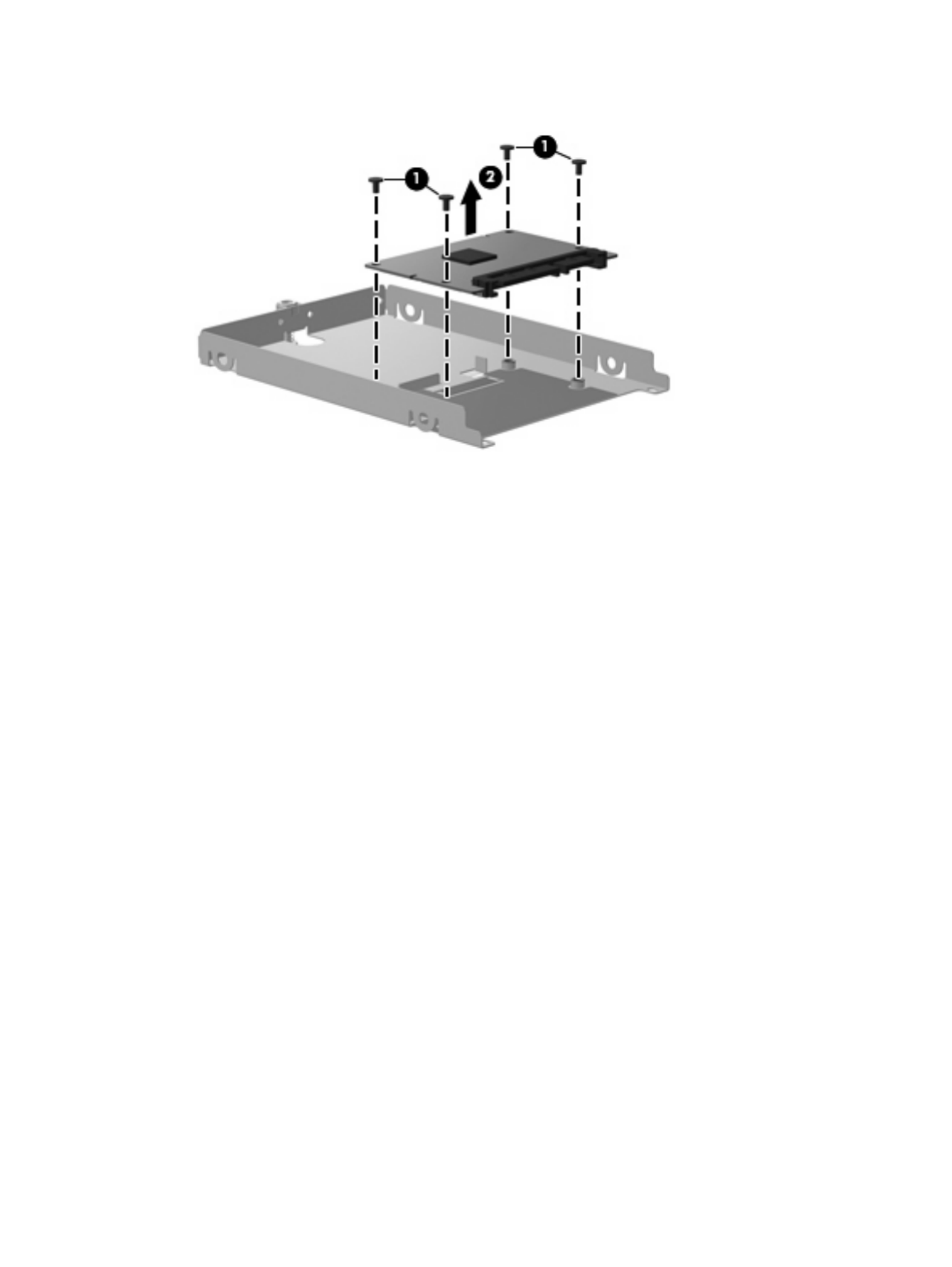
2. Lift the solid-state drive (2) to remove it.
Reverse this procedure to install a solid-state drive.
Component replacement procedures 47

Top cover
Description Spare part number
Top cover (includes TouchPad) 537622-001
Before removing the top cover, follow these steps:
1. Shut down the device. If you are unsure whether the device is off or in Hibernation, turn the device
on, and then shut it down through the operating system.
2. Disconnect all external devices connected to the device.
3. Disconnect the power from the device by first unplugging the power cord from the AC outlet and
then unplugging the AC adapter from the device.
4. Remove the battery (see Battery on page 36).
5. If your device has WWAN capability, remove the SIM (see SIM on page 37.
6. Remove the memory module (see Memory module on page 38
7. Remove the keyboard (see Keyboard on page 40).
8. Remove the hard drive or solid-state drive assembly (see Mass storage devices on page 45).
Remove the top cover.
1. Turn the device upside down, with the front toward you.
2. Use a thin, flat tool to release the 4 tethered rubber feet.
3. Remove the four Phillips PM2.5×7.0 screws (1), and the Phillips SP2.0×5.0 screw (2) that secure
the top cover to the base enclosure.
4. Turn the device right-side up, with the front toward you.
5. Open the device as far as possible.
48 Chapter 4 Removal and replacement procedures

6. Remove the 8 Phillips PM2.5×7.0 screws that secure the top cover to the base enclosure.
7. Lift the inside edge of the top cover (1) and swing it up. Then slide the top cover back slightly to
rest against the display assembly (2) at an angle.
8. Release the ZIF connector (1) to which the TouchPad button board cable is connected.
Component replacement procedures 49

WLAN module
Description Spare part number
Broadcom 4312 802.11/b/g WLAN module
For use in Canada, the Cayman Islands, Guam, Puerto Rico, the U.S. Virgin Islands,
and the United States
504593-003
For use in Afghanistan, Albania, Algeria, Andorra, Angola, Antigua and Barbuda, Argentina, Armenia,
Aruba, Australia, Austria, Azerbaijan, the Bahamas, Bahrain, Bangladesh, Barbados, Belarus,
Belgium, Belize, Benin, Bermuda, Bhutan, Bolivia, Bosnia and Herzegovina, Botswana, Brazil,
the British Virgin Islands, Brunei, Bulgaria, Burkina Faso, Burundi, Cameroon, Cape Verde,
the Central African Republic, Chad, Chile, the People's Republic of China, Colombia, Comoros,
the Congo, Costa Rica, Croatia, Cyprus, the Czech Republic, Denmark, Djibouti, Dominica,
the Dominican Republic, East Timor, Ecuador, Egypt, El Salvador, Equatorial Guinea, Eritrea, Estonia,
Ethiopia, Fiji, Finland, France, French Guiana, Gabon, Gambia, Georgia, Germany, Ghana, Gibraltar,
Greece, Grenada, Guadeloupe, Guatemala, Guinea, Guinea-Bissau, Guyana, Haiti, Honduras,
Hong Kong, Hungary, Iceland, India, Ireland, Israel, Italy, the Ivory Coast, Jamaica, Jordan,
Kazakhstan, Kenya, Kiribati, Kyrgyzstan, Laos, Latvia, Lebanon, Lesotho, Liberia, Liechtenstein,
Lithuania, Luxembourg, Macedonia, Madagascar, Malawi, Malaysia, the Maldives, Mali, Malta,
the Marshall Islands, Martinique, Mauritania, Mauritius, Mexico, Micronesia, Monaco, Mongolia,
Montenegro, Morocco, Mozambique, Namibia, Nauru, Nepal, the Nether Antilles, the Netherlands,
New Zealand, Nicaragua, Niger, Nigeria, Norway, Oman, Pakistan, Palau, Panama,
Papua New Guinea, Paraguay, Peru, the Philippines, Poland, Portugal, the Republic of Moldova,
Romania, Russia, Rwanda, Samoa, San Marino, Sao Tome and Principe, Saudi Arabia, Senegal,
Serbia, the Seychelles, Sierra Leone, Singapore, Slovakia, Slovenia, the Solomon Islands, Somalia,
South Africa, South Korea, Spain, Sri Lanka, St. Kitts and Nevis, St. Lucia,
St. Vincent and the Grenadines, Suriname, Swaziland, Sweden, Switzerland, Taiwan, Tajikistan,
Tanzania, Togo, Tonga, Trinidad and Tobago, Tunisia, Turkey, Turkmenistan, Tuvalu, Uganda,
Ukraine, the United Arab Emirates, the United Kingdom, Uruguay, Uzbekistan, Vanuatu, Venezuela,
Vietnam, Yemen, Zaire, Zambia, and Zimbabwe
504593-004
CAUTION: The WWAN module and the WLAN module are not interchangeable.
To prevent an unresponsive system, replace the wireless module only with a wireless module authorized
for use in the device by the governmental agency that regulates wireless devices in your country or
region. If you replace the module and then receive a warning message, remove the module to restore
device functionality, and then contact technical support through Help and Support.
Before removing the WLAN module, follow these steps:
1. Shut down the device. If you are unsure whether the device is off or in Hibernation, turn the device
on, and then shut it down through the operating system.
2. Disconnect all external devices connected to the device.
3. Disconnect the power from the device by first unplugging the power cord from the AC outlet and
then unplugging the AC adapter from the device.
4. Remove the battery (see Battery on page 36).
5. If your device has WWAN capability, remove the SIM (see SIM on page 37.
6. Remove the following components:
a. Keyboard (see Keyboard on page 40)
b. Hard drive or solid-state drive (see Mass storage devices on page 45)
c. Top cover (see Top cover on page 48)
Component replacement procedures 51

WWAN module
NOTE: Not available for computers with Mobile Mi installed.
Description Spare part number
HP un2400 Mobile Broadband Module (select models only) 483377-002
HP un2400 Mobile Broadband Module for use only with Verizon Wireless (select models only) 483377-003
WWAN module for use only in China 571888-001
CAUTION: The WWAN module and the WLAN module are not interchangeable.
To prevent an unresponsive system, replace the wireless module only with a wireless module authorized
for use in the device by the governmental agency that regulates wireless devices in your country or
region. If you replace the module and then receive a warning message, remove the module to restore
device functionality, and then contact technical support.
Before removing the WWAN module, follow these steps:
1. Shut down the device. If you are unsure whether the device is off or in Hibernation, turn the device
on, and then shut it down through the operating system.
2. Disconnect all external devices connected to the device.
3. Disconnect the power from the device by first unplugging the power cord from the AC outlet and
then unplugging the AC adapter from the device.
4. Remove the battery (see Battery on page 36).
5. Remove the SIM (see SIM on page 37.
6. Remove the following components:
a. Keyboard (see Keyboard on page 40)
b. Hard drive or solid-state drive (see Mass storage devices on page 45)
c. Top cover (see Top cover on page 48)
Remove the WWAN module:
1. Remove the 2 Phillips PM2.0×4.0 screws (1) (3) that secure the WWAN connector module to the
system board. (The edge of the module opposite the slot rises away from the device.)
2. Disconnect the wireless antenna cables (2) from the terminals on the WWAN module.
NOTE: The red WWAN antenna cable is connected to the WWAN module “Main” terminal. The
blue WWAN antenna cable is connected to the WWAN module “Aux” terminal.
Component replacement procedures 53

3. Remove the WWAN module (3) by pulling the module away from the slot at an angle.
Reverse this procedure to install the WWAN module.
54 Chapter 4 Removal and replacement procedures

USB/audio board
Description Spare part number
USB/audio board (includes cable) 537614-001
Before removing the USB/audio board, follow these steps:
1. Shut down the computer. If you are unsure whether the computer is off or in Hibernation, turn the
computer on, and then shut it down through the operating system.
2. Disconnect all external devices connected to the computer.
3. Disconnect the power from the computer by first unplugging the power cord from the AC outlet and
then unplugging the AC Adapter from the computer.
4. Remove the battery (see Battery on page 36).
5. If your device has WWAN capability, remove the SIM (see SIM on page 37.
6. Remove the following components:
a. Keyboard (see Keyboard on page 40).
b. Hard drive or solid-state drive (see Mass storage devices on page 45).
c. Top cover (see Top cover on page 48).
Remove the USB board:
1. Release the ZIF connector (1) to which the USB/audio board cable is connected, and disconnect
the cable (2).
2. Release the USB/audio board from the clip attached to the base enclosure (3), and remove the
USB/audio board (4).
Reverse this procedure to install the USB/audio board.
Component replacement procedures 55

Power/battery pass-through board
Description Spare part number
Power/battery passthrough board 537615-001
Before removing the power/battery pass-through board, follow these steps:
1. Shut down the device. If you are unsure whether the device is off or in Hibernation, turn the device
on, and then shut it down through the operating system.
2. Disconnect all external devices connected to the device.
3. Disconnect the power from the device by first unplugging the power cord from the AC outlet and
then unplugging the AC adapter from the device.
4. Remove the battery (see Battery on page 36).
5. If your device has WWAN capability, remove the SIM (see SIM on page 37.
6. Remove the following components:
a. Keyboard (see Keyboard on page 40)
b. Hard drive or solid-state drive (see Mass storage devices on page 45)
c. Top cover (see Top cover on page 48)
Remove the power/battery pass-through board:
1. Disconnect the power cable (1).
2. Remove the 2 Phillips BP2.5×5.0 screws (2) that secure the power/battery passthrough board to
the base enclosure.
3. Remove the power/battery pass-through board (3).
Reverse this procedure to install the power/battery pass-through board.
56 Chapter 4 Removal and replacement procedures

Fan
Description Spare part number
Fan 537613-001
NOTE: To properly ventilate the device, allow at least a 7.6-cm (3-inch) clearance on the left side of
the device. The device uses an electric fan for ventilation. The fan is controlled by a temperature sensor
and is designed to turn on automatically when high temperature conditions exist. These conditions are
affected by high external temperatures, system power consumption, power management/battery
conservation configurations, battery fast charging, and software requirements. Exhaust air is displaced
through the ventilation grill located on the left side of the device.
Before removing the fan, follow these steps:
1. Shut down the device. If you are unsure whether the device is off or in Hibernation, turn the device
on, and then shut it down through the operating system.
2. Disconnect all external devices connected to the device.
3. Disconnect the power from the device by first unplugging the power cord from the AC outlet and
then unplugging the AC adapter from the device.
4. Remove the battery (see Battery on page 36).
5. If your device has WWAN capability, remove the SIM (see SIM on page 37.
6. Remove the following components:
a. Keyboard (see Keyboard on page 40)
b. Hard drive or solid-state drive (see Mass storage devices on page 45)
c. Top cover (see Top cover on page 48)
Remove the fan:
1. Disconnect the fan cable (1).
2. Remove the 2 Phillips PM2.5×5.0 screws (2) that secure the fan to the base enclosure.
Component replacement procedures 57
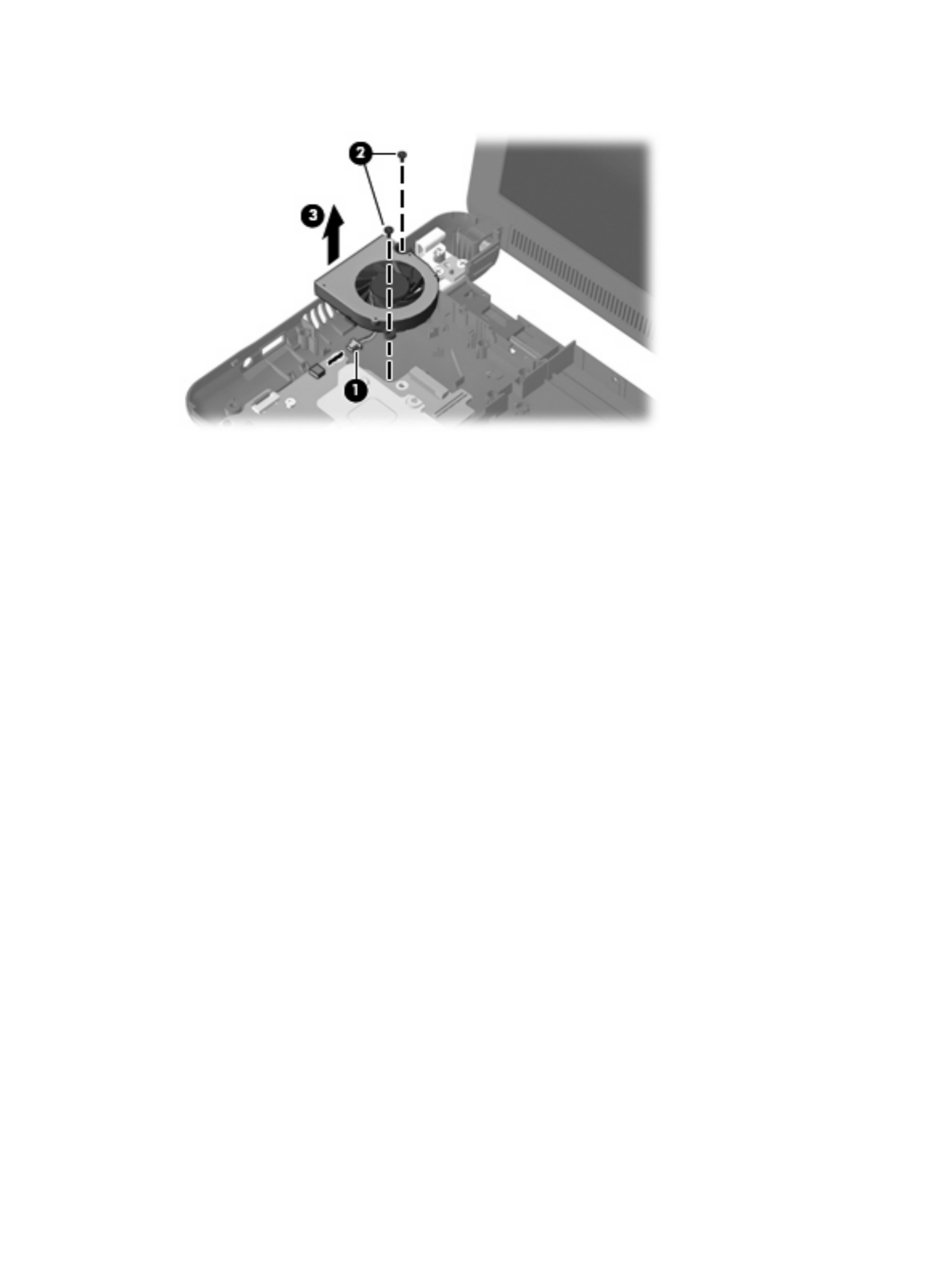
3. Remove the fan (3).
Reverse this procedure to install the fan.
58 Chapter 4 Removal and replacement procedures

Heat sink assembly
Description Spare part number
Heat sink assembly (includes replacement thermal material) 537619-001
Before removing the heat sink assembly, follow these steps:
1. Shut down the device. If you are unsure whether the device is off or in Hibernation, turn the device
on, and then shut it down through the operating system.
2. Disconnect all external devices connected to the device.
3. Disconnect the power from the device by first unplugging the power cord from the AC outlet and
then unplugging the AC adapter from the device.
4. Remove the battery (see Battery on page 36).
5. If your device has WWAN capability, remove the SIM (see SIM on page 37.
6. Remove the following components:
a. Keyboard (see Keyboard on page 40)
b. Hard drive or solid-state drive (see Mass storage devices on page 45)
c. Top cover (see Top cover on page 48)
d. WLAN module (see WLAN module on page 51)
e. Fan (see Fan on page 57)
Remove the heat sink assembly:
1. Remove the 4 Phillips SP1.5×1.05 screws (1) that secure the heat sink assembly to the system
board.
NOTE: The screws are numbered 1 through 4. Follow this order when removing the screws.
Component replacement procedures 59

2. Remove the heat sink assembly (2).
NOTE: Due to the adhesive quality of the thermal material located between the heat sink
assembly and system board components, it may be necessary to move the heat sink assembly
from side to side to detach the assembly.
NOTE: The thermal material must be thoroughly cleaned from the surfaces of the heat sink
assembly and the system board each time the heat sink assembly is removed. Thermal paste is
used on the processor (1), and thermal tape is used on the Northbridge chip (2). Replacement
thermal material is included with all heat sink assembly and system board spare part kits.
Reverse this procedure to install the heat sink assembly.
60 Chapter 4 Removal and replacement procedures

System board
Description Spare part number
System board (includes processor and replacement thermal material)
Includes Intel Atom N280 1.66-GHz processor, 512-KB Level 2 cache, 533-MHz front-side bus (FSB) 571370-001
Includes Intel Atom N270 1.6-GHz processor, 512-KB Level 2 cache, 533-MHz front-side bus (FSB) 537662-001
Before removing the system board, follow these steps:
1. Shut down the device. If you are unsure whether the device is off or in Hibernation, turn the device
on, and then shut it down through the operating system.
2. Disconnect all external devices connected to the device.
3. Disconnect the power from the device by first unplugging the power cord from the AC outlet and
then unplugging the AC adapter from the device.
4. Remove the battery (see Battery on page 36).
5. If your device has WWAN capability, remove the SIM (see SIM on page 37.
6. Remove the following components:
a. Keyboard (see Keyboard on page 40)
b. Hard drive or solid-state drive (see Mass storage devices on page 45)
c. Top cover (see Top cover on page 48)
When replacing the system board, be sure that the following components are removed from the defective
system board and installed on the replacement system board:
●WLAN module (see WLAN module on page 51)
●WWAN module, if included (see WWAN module on page 53)
●RTC battery (see RTC battery on page 44)
●Heat sink assembly (see Heat sink assembly on page 59)
Remove the system board:
1. Release the tape securing the WWAN antennas(1).
Component replacement procedures 61
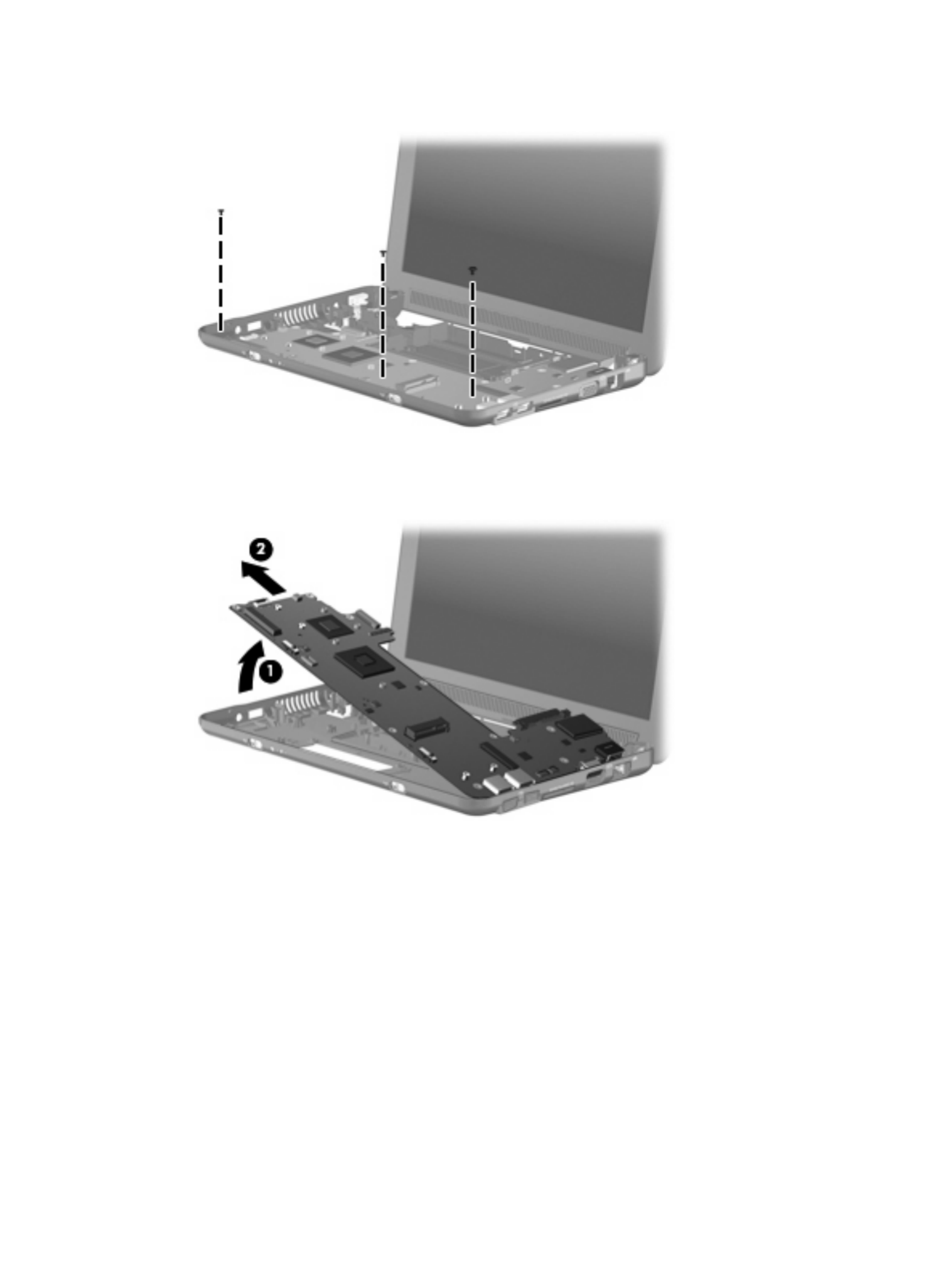
5. Remove the 3 Phillips PM2.5×5.0 screws that secure the system board to the base enclosure.
6. Grasp the system board at the midpoint of the left side (1), and lift it up.
7. Pull the system board (2) out to the left at an angle to remove it.
8. Remove the system board.
Reverse the procedure to install the system board.
Component replacement procedures 63

Before removing the display assembly, follow these steps:
1. Shut down the device. If you are unsure whether the device is off or in Hibernation, turn the device
on, and then shut it down through the operating system.
2. Disconnect all external devices connected to the device.
3. Disconnect the power from the device by first unplugging the power cord from the AC outlet and
then unplugging the AC adapter from the device.
4. Remove the battery (see Battery on page 36).
5. If your device has WWAN capability, remove the SIM (see SIM on page 37.
6. Remove the following components:
a. Keyboard (see Keyboard on page 40)
b. Hard drive or solid-state drive (see Mass storage devices on page 45)
c. Top cover (see Top cover on page 48)
Remove the display assembly:
1. Release the tape securing the WWAN antennas(1).
2. Disconnect the following cables from the system board:
(2) Display panel cable
(3) Microphone cable
(4) Speaker cable
(5) WLAN cables
(6) WWAN cables (select models only)
CAUTION: Support the display assembly when removing the following screws. Failure to support
the display assembly can result in damage to the display assembly and other device components.
Component replacement procedures 65

3. Remove the 4 Phillips PM2.5×5.0 screws (1) that secure the display assembly to the device.
NOTE: One screw on the left hinge (2) also secures the display panel cable ground strap.
4. Remove the display assembly.
5. If it is necessary to replace the display bezel, perform the following steps:
a. Remove the display hinge covers (1).
b. Flex the inside edges of the top and bottom (2), and then the left and right sides (3) of the
display bezel until the bezel disengages from the display enclosure.
c. Remove the display bezel (4).
66 Chapter 4 Removal and replacement procedures
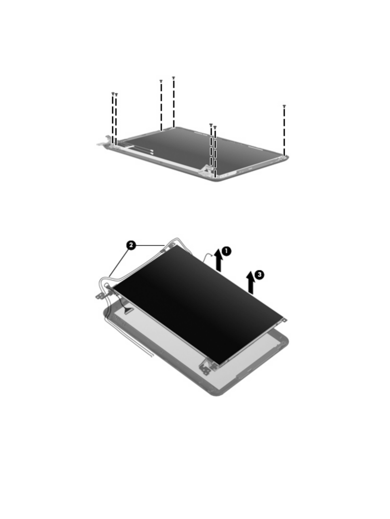
6. If it is necessary to replace the display panel, perform the following steps:
a. Remove the 7 Phillips PM2.0×3.0 screws that secure the display panel to the display
enclosure.
b. Lift the display panel up from the display enclosure (1).
c. Disconnect the webcam cable (2) from the system board (2)
d. Remove the display panel (3) from the display enclosure.
7. If it is necessary to replace the speaker assembly, perform the following steps:
a. Remove the three Phillips PM2.0×3.0 screws (1) that secure the speaker assembly to the
display enclosure.
Component replacement procedures 67

b. Remove the speaker assembly (2).
8. If it is necessary to replace the display hinges, perform the following steps:
a. Remove the 2 Phillips PM2.0×3.0 screws (1) that secure each hinge to the display enclosure.
b. Remove the hinges (2).
9. If it is necessary to replace the display panel cable, perform the following steps:
a. Peel back the Mylar protection on the back of the display panel (1).
68 Chapter 4 Removal and replacement procedures

b. Pull the receiver through the tabs (2), and remove the microphone receiver (3).
12. If it is necessary to replace the wireless antenna transceivers and cables, detach the cables from
the adhesive (1) that secures them to the display enclosure, and then remove the cables (2).
Reverse this procedure to reassemble and install the display assembly.
70 Chapter 4 Removal and replacement procedures

5 Setup Utility
Starting the Setup Utility
The Setup Utility is a ROM-based information and customization utility that can be used even when your
operating system is not working.
The utility reports information about the device and provides settings for startup, security, and other
preferences.
To start the Setup Utility:
Open the Setup Utility by turning on or restarting the device, and then pressing f10 while the “F10
= BIOS Setup Options” message is displayed in the lower-left corner of the screen.
Using the Setup Utility
Changing the language of the Setup Utility
The following procedure explains how to change the language of the Setup Utility. If the Setup Utility is
not already running, begin at step 1. If the Setup Utility is already running, begin at step 2.
1. Open the Setup Utility by turning on or restarting the device, and then pressing f10 while the “F10
= BIOS Setup Options” message is displayed in the lower-left corner of the screen.
2. Use the arrow keys to select System Configuration .> Language, and then press enter
3. Use the arrow keys to select a language, and then press enter.
4. When a confirmation prompt with your language selected is displayed, press enter.
5. To save your change and exit the Setup Utility, use the arrow keys to select Exit > Exit Saving
Changes, and then press enter.
Your change goes into effect immediately.
Navigating and selecting in the Setup Utility
Because the Setup Utility is not operating system–based, it does not support the TouchPad. Navigation
and selection are by keystroke.
●To choose a menu or a menu item, use the arrow keys.
●To choose an item in a list or to toggle a field, for example an Enable/Disable field, use either the
arrow keys or f5 or f6.
Starting the Setup Utility 71

●To select an item, press enter.
●To close a text box or return to the menu display, press esc.
●To display additional navigation and selection information while the Setup Utility is open, press
f1.
Displaying system information
The following procedure explains how to display system information in the Setup Utility. If the Setup
Utility is not open, begin at step 1. If the Setup Utility is open, begin at step 2.
1. Open the Setup Utility by turning on or restarting the device, and then pressing f10 while the “F10
= BIOS Setup Options” message is displayed in the lower-left corner of the screen.
2. Select the Main menu. System information such as the system time and date, and identification
information about the device is displayed.
3. To exit the Setup Utility without changing any settings, use the arrow keys to select Exit Exit >
Discarding Changes, and then press enter.
Restoring default settings in the Setup Utility
The following procedure explains how to restore the Setup Utility default settings. If the Setup Utility is
not already running, begin at step 1. If the Setup Utility is already running, begin at step 2.
1. Open the Setup Utility by turning on or restarting the device, and then pressing f10 while the “F10
= BIOS Setup Options” message is displayed in the lower-left corner of the screen.
2. Use the arrow keys to select Exit > Load Setup Defaults, and then press enter.
3. When the Setup Confirmation is displayed, press enter.
4. To save your change and exit the Setup Utility, use the arrow keys to select Exit > Exit Saving
Changes, and then press enter.
The Setup Utility default settings go into effect when the device restarts.
NOTE: Your password, security, and language settings are not changed when you restore the factory
default settings.
Exiting the Setup Utility
You can exit the Setup Utility with or without saving changes.
●To exit the Setup Utility and save your changes from the current session:
If the Setup Utility menus are not visible, press esc to return to the menu display. Then use the
arrow keys to select Exit > Exit Saving Changes, and then press enter.
●To exit the Setup Utility without saving your changes from the current session:
If the Setup Utility menus are not visible, press esc to return to the menu display. Then use the
arrow keys to select Exit > Exit Discarding Changes, and then press enter.
After either choice, the device restarts and loads the operating system.
72 Chapter 5 Setup Utility

Setup Utility menus
The menu tables in this section provide an overview of Setup Utility options.
NOTE: Some of the Setup Utility menu items listed in this chapter may not be supported by your device.
Main menu
Select To do this
System information ●View and change the system time and date.
●View identification information about the device.
●View specification information about the processor, memory size,
and system BIOS.
Security menu
Select To do this
Administrator password Enter, change, or delete an administrator password.
Power-On Password Enter, change, or delete a power-on password.
System Configuration menu
Select To do this
Language Support Change the Setup Utility language.
Processor C4 State Enable/disable the processor C4 sleep state.
Boot Options Set the following boot options:
●f10 f10 f12 and f12 Delay (sec.)―Set the delay for the and functions
of the Setup Utility in intervals of 5 seconds each (0, 5, 10, 15, 20).
●Internal Network Adapter boot―Enable/disable boot from Internal
Network Adapter.
●Boot Order―Set the boot order for:
◦Internal hard drive (select models only)
◦USB Floppy
◦USB CD/DVD ROM Drive
◦USB flash drive
◦USB Hard drive
◦USB Card Reader
◦Network adapter
NOTE: Only the devices attached to the system will appear
in the boot order menu.
Setup Utility menus 73

Diagnostics menu
Select To do this
Hard Disk Self Test (select models only) Run a comprehensive self-test on the hard drive.
Memory Test Run a diagnostic test on the system memory.
74 Chapter 5 Setup Utility

6 Specifications
Device specifications
Metric U.S.
Dimensions
Depth 16.67 cm 6.56 in
Width 26.17 cm 10.30 in
Height 2.52 cm 0.99 in
Weight
10.1-in. LCD, equipped with a 3-cell battery, hard drive, 1-GB
memory, WLAN module, and 2 wireless antennas
1.11 kg 2.45 lb
10.1-in. LCD, equipped with a 3-cell battery,solid-state drive,
1-GB memory, WLAN module, and 2 wireless antennas
1.09 kg 2.40 lb
Input power
Operating voltage 19 V dc @ 1.58 A – 30 W
Operating current 1.58 A
Temperature
Operating 5°C to 35°C 41°F to 95°F
Nonoperating -20°C to 65°C -4°F to 149°F
Relative humidity (noncondensing)
Operating 10% to 90%
Nonoperating 0% to 95%
Maximum altitude (unpressurized)
Operating -15 m to 3,048 m -50 ft to 10,000 ft
Nonoperating -15 m to 12,192 m -50 ft to 40,000 ft
NOTE: Applicable product safety standards specify thermal limits for plastic surfaces. The device operates well within this
range of temperatures.
Device specifications 75

10.1-inch, AntiGlare display specifications
Metric U.S.
Dimensions
Height 23.45 cm 9.23 in
Width 14.30 cm 5.62 in
Diagonal 25.55 cm 10.05 in
Number of colors 262,144
Contrast ratio 400:1 (typical)
Brightness 200 nits (typical)
Pixel resolution
Pitch 0.2175 × 0.2175 mm
Format 1024 × 576
Configuration RGB vertical stripe
Backlight Edge lit
Character display 80 × 25
Total power consumption 3.2 W
Viewing angle +/-45° horizontal, +15/-35° vertical (typical)
76 Chapter 6 Specifications

Hard drive specifications
60-GB *
Dimensions
Height 9.5 mm
Width 70 mm
Weight 101 g
Interface type PATA
Transfer rate 100 MB/sec
Security ATA security
Seek times (typical read, including setting)
Single track 3 ms
Average 13 ms
Maximum 24 ms
Logical blocks 117,210,240
Disc rotational speed 4200 rpm
Operating temperature
* 1 GB = 1 billion bytes when referring to hard drive storage capacity. Actual accessible capacity is less. Actual drive
specifications may differ slightly.
NOTE: Certain restrictions and exclusions apply. Contact technical support for details.
Hard drive specifications 77

Solid-state drive specifications
Performance
Transfer modes supported UDMA 0-4, Multiword-DMA 0-2, PIO 0-4
Sustained read 39 MB/sec
Sustained write 17 MB/sec
Characteristics
Interface Parallel ATA (PATA)
MLC NAND flash capacity 8 GB, 16 GB
Electrical specifications
DC supply voltage 3.3 V +/– 5%
Standby current 300 µA (typical)
Active current Read = 130 mA (typical)
Write = 120 mA (typical)
Environmental specifications
Operating temperature 0°C to +70°C (32°F to 158°F)
Storage temperature -25°C to +85°C (-13°F to 185°F)
Operating altitude up to 24,384 m (80,000 feet)
Humidity 5% to 90% non-condensing
Shock 1,000 g
Acoustic noise 0 dB
Vibration 15 g (peak to peak)
Physical specifications
Connector 40-pin ZIF connector
Weight (8-GB model) 5.5 g
Weight (16-GB model) 7.0 g
Dimensions (8-GB model) 54 × 32 × 2.6 mm
Dimensions (16-GB model) 54 × 32 × 3.75 mm
Regulations and compliance RoHS, China RoHS, SGS ROHS, FCC, CE
UL – PCB Only
78 Chapter 6 Specifications

System DMA specifications
Hardware DMA System function
DMA0 Not applicable
DMA1 * Not applicable
DMA2 * Not applicable
DMA3 Not applicable
DMA4 Direct memory access controller
System DMA specifications 79

System interrupt specifications
Hardware IRQ System function
IRQ0 System timer
IRQ1 Standard 101-/102-Key or Microsoft® Natural PS/2 Keyboard
IRQ8 System CMOS/real-time clock
IRQ9 * Microsoft ACPI-compliant system
IRQ12 Synaptics PS/2 TouchPad
IRQ13 Numeric data processor
IRQ14 Primary IDE channel
IRQ15 Intel® 82801G (ICH7 Family) SMBus Controller—27DA
IRQ16 Broadcom 802.11b/g WLAN no. 2
Intel 82801G (ICH7 Family) PCI Express Root Port—27D0
Intel 82801G (ICH7 Family) USB Universal Host Controller—27CB
Microsoft UAA Bus Driver for High Definition Audio
Mobile Intel 945 Express Chipset Family
IRQ17 Intel 82801G (ICH7 Family) PCI Express Root Port—27D2
IRQ18 Intel 82801G (ICH7 Family) USB Universal Host Controller—27CA
IRQ19 Intel 82801G (ICH7 Family) USB Universal Host Controller—27C9
IRQ23 Intel 82801G (ICH7 Family) USB Universal Host Controller—27C8
Intel 82801G (ICH7 Family) USB2 Enhanced Host Controller—27CC
* Default configuration
80 Chapter 6 Specifications

System I/O address specifications
I/O address (hex) System function (shipping configuration)
000 - 00F DMA controller
000 - CF7 PCI bus
010 - 01F Motherboard resources
020 - 021 Programmable interrupt controller
022 - 03F Motherboard resources
040 - 043 System timer
044 - 05F Motherboard resources
060 - 060 Standard 101-/102-Key or Microsoft® Natural PS/2 Keyboard
061 - 061 System speaker
062 - 062 Microsoft ACPI-Compliant Embedded Controller
063- 063 Motherboard resources
064 - 064 Standard 101-/102-Key or Microsoft Natural PS/2 Keyboard
065 - 065 Motherboard resources
066 - 066 Microsoft ACPI-Compliant Embedded Controller
067 - 06F Motherboard resources
070 - 071 System CMOS/real-time clock
072 - 07F Motherboard resources
080 - 080 Motherboard resources
081 - 083 DMA controller
084 - 086 Motherboard resources
087 - 087 DMA controller
088 - 088 Motherboard resources
089 - 08B DMA controller
08C - 08E Motherboard resources
08F - 08F DMA controller
090 - 09F Motherboard resources
0A0 - 0A1 Programmable interrupt controller
0A2 - 0BF Motherboard resources
0C0 - 0DF DMA controller
0E0 - 0EF Motherboard resources
0F0 - 0FF Numeric data processor
1F0 - 1F7 Primary IDE channel
274 - 277 ISAPNP Read Data Port
System I/O address specifications 81
Specyfikacje produktu
| Marka: | HP |
| Kategoria: | laptop |
| Model: | Mini 110-1112NR |
Potrzebujesz pomocy?
Jeśli potrzebujesz pomocy z HP Mini 110-1112NR, zadaj pytanie poniżej, a inni użytkownicy Ci odpowiedzą
Instrukcje laptop HP

4 Marca 2025
17 Lutego 2025
6 Lutego 2025
12 Stycznia 2025
11 Stycznia 2025
28 Grudnia 2024
27 Grudnia 2024
27 Grudnia 2024
21 Grudnia 2024
21 Grudnia 2024
Instrukcje laptop
- laptop Sony
- laptop Samsung
- laptop Fellowes
- laptop LG
- laptop Xiaomi
- laptop Huawei
- laptop Lenovo
- laptop Gigabyte
- laptop Acer
- laptop Fujitsu
- laptop Panasonic
- laptop Viewsonic
- laptop Asus
- laptop Medion
- laptop MSI
- laptop Toshiba
- laptop Haier
- laptop Prixton
- laptop Hyundai
- laptop Honor
- laptop Tripp Lite
- laptop Zebra
- laptop Dell
- laptop Schneider
- laptop Thomson
- laptop Pyle
- laptop Apple
- laptop Razer
- laptop ADATA
- laptop GoClever
- laptop SPC
- laptop NEC
- laptop Oregon Scientific
- laptop Jay-Tech
- laptop Microsoft
- laptop ECS
- laptop XPG
- laptop Denver
- laptop Lexibook
- laptop Micromax
- laptop Odys
- laptop TechBite
- laptop TrekStor
- laptop Alienware
- laptop Airis
- laptop Emachines
- laptop Hähnel
- laptop Sylvania
- laptop Coby
- laptop Evga
- laptop Naxa
- laptop Ricatech
- laptop Mpman
- laptop Vizio
- laptop Targa
- laptop Peaq
- laptop Ematic
- laptop Hannspree
- laptop Inovia
- laptop Ergotron
- laptop Ibm
- laptop Atdec
- laptop Packard Bell
- laptop Compaq
- laptop SIIG
- laptop Hercules
- laptop Kogan
- laptop Getac
- laptop Vulcan
- laptop System76
- laptop General Dynamics Itronix
- laptop CTL
- laptop Everex
- laptop Olidata
- laptop Dynabook
- laptop Hamilton Buhl
- laptop AORUS
- laptop Humanscale
- laptop Aplic
- laptop Schenker
Najnowsze instrukcje dla laptop

3 Kwietnia 2025

2 Kwietnia 2025

28 Marca 2025

28 Marca 2025
26 Marca 2025
13 Marca 2025
7 Marca 2025
1 Marca 2025
26 Lutego 2025
23 Lutego 2025