Instrukcja obsługi HP Compaq Presario CQ57
Przeczytaj poniżej 📖 instrukcję obsługi w języku polskim dla HP Compaq Presario CQ57 (117 stron) w kategorii laptop. Ta instrukcja była pomocna dla 3 osób i została oceniona przez 2 użytkowników na średnio 4.5 gwiazdek
Strona 1/117

Compaq Presario CQ57 Notebook PC
Maintenance and Service Guide

© Copyright 2011 Hewlett-Packard
Development Company, L.P.
AMD, the AMD Arrow logo, and
combinations thereof, are trademarks of
Advanced Micro Devices, Inc. Bluetooth is a
trademark owned by its proprietor and used
by Hewlett-Packard Company under license.
Intel, Celeron, and Pentium are trademarks
of Intel Corporation in the U.S. and other
countries. Microsoft and Windows are U.S.
registered trademarks of Microsoft
Corporation. SD Logo is a trademark of
its proprietor.
The information contained herein is subject
to change without notice. The only
warranties for HP products and services are
set forth in the express warranty statements
accompanying such products and services.
Nothing herein should be construed as
constituting an additional warranty. HP shall
not be liable for technical or editorial errors
or omissions contained herein.
Third Edition: August 2011
First Edition: March 2011
Document Part Number: 638662-003

Safety warning notice
WARNING! To reduce the possibility of heat-related injuries or of overheating the device, do not
place the device directly on your lap or obstruct the device air vents. Use the device only on a hard, flat
surface. Do not allow another hard surface, such as an adjoining optional printer, or a soft surface,
such as pillows or rugs or clothing, to block airflow. Also, do not allow the AC adapter to contact the
skin or a soft surface, such as pillows or rugs or clothing, during operation. The device and the AC
adapter comply with the user-accessible surface temperature limits defined by the International
Standard for Safety of Information Technology Equipment (IEC 60950).
iii

iv Safety warning notice

Table of contents
1 Product description ........................................................................................................... 1
2 External component identification ..................................................................................... 7
Display ................................................................................................................................... 7
Button ..................................................................................................................................... 8
Keys ....................................................................................................................................... 9
Lights .................................................................................................................................... 10
TouchPad .............................................................................................................................. 11
Left side ................................................................................................................................ 12
Right side .............................................................................................................................. 13
Bottom .................................................................................................................................. 14
3 Illustrated parts catalog .................................................................................................. 15
Service tag ............................................................................................................................ 15
Computer major components ................................................................................................... 17
Cable Kit .............................................................................................................................. 22
Display assembly subcomponents ............................................................................................. 23
Mass storage devices ............................................................................................................. 24
Miscellaneous parts ................................................................................................................ 25
Plastics Kit ............................................................................................................................. 26
Sequential part number listing .................................................................................................. 27
4 Removal and replacement procedures ............................................................................ 32
Preliminary replacement requirements ....................................................................................... 32
Tools required ......................................................................................................... 32
Service considerations ............................................................................................. 32
Plastic parts ............................................................................................. 32
Cables and connectors ............................................................................. 32
Drive handling ......................................................................................... 33
Grounding guidelines .............................................................................................. 33
Electrostatic discharge damage .................................................................. 33
v

Packaging and transporting guidelines ........................................ 35
Component replacement procedures ........................................................................................ 37
Service tag ............................................................................................................. 37
Computer feet ......................................................................................................... 38
Battery ................................................................................................................... 39
Optical drive (select models only) .............................................................................. 40
WLAN module ........................................................................................................ 43
Memory module ...................................................................................................... 45
Hard drive ............................................................................................................. 46
Keyboard ............................................................................................................... 49
Top cover ............................................................................................................... 52
Power button board ................................................................................................. 56
TouchPad button board ............................................................................................ 57
USB board ............................................................................................................. 59
Power connector cable ............................................................................................ 60
Speakers ................................................................................................................ 62
Optical drive connector cable ................................................................................... 63
Display assembly .................................................................................................... 64
System board ......................................................................................................... 71
RTC battery ............................................................................................................ 74
Fan/heat sink assembly ........................................................................................... 76
Processor ............................................................................................................... 82
5 Setup Utility (BIOS) and System Diagnostics .................................................................... 84
Using Setup Utility .................................................................................................................. 84
Starting Setup Utility ................................................................................................ 84
Changing the language of Setup Utility ...................................................................... 84
Navigating and selecting in Setup Utility .................................................................... 85
Displaying system information ................................................................................... 85
Restoring factory settings in Setup Utility ..................................................................... 86
Exiting Setup Utility ................................................................................................. 86
Updating the BIOS .................................................................................................. 86
Determining the BIOS version .................................................................... 87
Downloading a BIOS update ..................................................................... 87
Using System Diagnostics ........................................................................................................ 88
6 Specifications ................................................................................................................. 89
Computer specifications .......................................................................................................... 89
15.6-inch display specifications ............................................................................................... 90
Hard drive specifications ........................................................................................................ 91
vi

7 Backup and recovery ...................................................................................................... 92
Restore ................................................................................................................................. 92
Creating restore media ........................................................................................................... 93
Performing a system restore ..................................................................................................... 94
Restoring using the dedicated recovery partition (select models only) ............................. 94
Restoring using the restore media .............................................................................. 95
Changing the computer boot order ............................................................................ 95
Backing up and recovering your information ............................................................................. 96
Using Windows Backup and Restore ......................................................................... 97
Using Windows system restore points ........................................................................ 97
When to create restore points .................................................................... 97
Create a system restore point ..................................................................... 98
Restore to a previous date and time ............................................................ 98
8 Power cord set requirements .......................................................................................... 99
Requirements for all countries .................................................................................................. 99
Requirements for specific countries and regions ....................................................................... 100
9 Recycling ...................................................................................................................... 101
Battery ................................................................................................................................ 101
Display ............................................................................................................................... 101
Index ............................................................................................................................... 107
vii

viii

1 Product description
Category Description Computer models
equipped with an
AMD processor
Computer models
equipped with an
Intel processor
Product Name Compaq Presario CQ57 Notebook PC √ √
Processors AMD® E450 1.65-GHz processor (dual core,
18 W)
√
AMD E350 1.60-GHz processor (dual core,
18 W)
√
AMD E300 1.30-GHz processor (dual core,
18 W)
√
AMD C50 1.00-GHz processor (1.0-
MB L2 cache, dual core, 9 W)
√
Intel Core i5-2430M 2.40-GHz processor
(1333-MHz FSB, 3.0-MB L3 cache, dual core,
35 W; not supported on computer models
equipped with Windows 7 Starter 32-bit
operating system)
√
Intel Core i3-2330M 2.20-GHz processor
(1333-MHz FSB, 3.0-MB L3 cache, dual core,
35 W; not supported on computer models
equipped with Windows 7 Starter 32-bit
operating system)
√
Intel Core i3-370M 2.40-GHz processor (1066-
MHz FSB, 3.0-MB L3 cache, dual core, 35 W;
not supported on computer models equipped
with Windows 7 Starter 32-bit
operating system)
√
Intel Pentium P6300 2.26-GHz processor (3.0-
MB L3 cache, dual core, 35 W)
√
Intel Pentium P6200 2.13-GHz processor (3.0-
MB L3 cache, dual core, 35 W)
√
Intel Pentium B960 2.20-GHz processor (2.0-
MB L2 cache, dual core, TJ85, 35 W; not
supported on computer models equipped with
Windows 7 Starter 32-bit operating system)
√
1

Category Description Computer models
equipped with an
AMD processor
Computer models
equipped with an
Intel processor
Intel Pentium B950 2.10-GHz processor (2.0-
MB L2 cache, dual core, TJ85, 35 W; not
supported on computer models equipped with
Windows 7 Starter 32-bit operating system)
√
Intel Celeron B800 1.50-GHz processor (2.0-
MB L3 cache, dual core, 35 W)
√
Intel Celeron B710 1.50-GHz processor (1.0-
MB L3 cache, single core, 35 W)
√
Intel Celeron DC T3500 2.10-GHz processor
(1.0-MB L2 cache, 800-MHz FSB)
√
Intel Celeron DC T3300 2.00-GHz processor
(1.0-MB L2 cache, 800-MHz FSB)
√
Intel Celeron SC C925 2.30-GHz processor
(1.0-MB L2 cache, 800-MHz FSB)
√
Intel Celeron SC C900 2.20-GHz processor
(1.0-MB L2 cache, 800-MHz FSB)
√
Chipset AMD A50M fusion controller hub (FCH) √
:Northbridge
●Intel HM65 Express Chipset
●Intel HM55 Express Chipset
√
Graphics AMD Radeon™ HD 6320M discrete-class
graphics supporting DX11
AMD Radeon™ HD 6310M discrete-class
graphics supporting DX11
Support for high-definition DVD playback with
HD-decode and DX10 and DX11 support
√
Internal graphics:
●Intel HD 3000 graphics on computer
models equipped with an Intel Core i5 or
i3 processor
●Intel HD graphics on computer models
equipped with an Intel Celeron or
Pentium processor
√
Discrete graphics: AMD Radeon HD 6370M
Graphics with 512-MB of discrete video
memory (64M×16 DDR3 900 MHz × 4 PCs)
√
2 Chapter 1 Product description

Category Description Computer models
equipped with an
AMD processor
Computer models
equipped with an
Intel processor
Switchable discrete graphics (not
supported on computer models equipped with
Windows 7 Starter OS): AMD Radeon HD
6470M Graphics with 512-MB of discrete
video memory (64M×16 DDR3 900 MHz × 4
PCs) or AMD Radeon HD 6470M Graphics
with 1024-MB of discrete video memory
(128M×16 DDR3 900 MHz × 4 PCs)
√
Support for high-definition DVD playback with
HD-decode ,and DX10 (UMA) and DX11
(discrete) support
√
Panel 15.6-in, high-definition (HD), light-emitting
diode (LED), SVA BrightView (1366×768)
display; typical brightness: 200 nits
All display assemblies include 1 or 2 wireless
local area network (WLAN) antenna cables
Supports 16:9 ultra wide aspect ratio
√ √
Memory 2 customer-accessible/upgradable memory
module slots
√ √
Supports dual-channel memory √ √
Supports up to 8192 GB of system RAM √ √
DDR3/1333-MHz √ √
Supports the following configurations:
●8192-MB total system memory (4096×2;
not supported on a 32-bit
operating system)
●4096-MB total system memory (4096×1
or 2048×2; not supported with
Windows® 7 Starter OS)
●3072-MB total system memory (2048×1 +
1024×1; not supported with Windows® 7
Starter OS)
●2048-MB total system memory (2048×1
or 1024×2)
●1024-MB total system memory (1024×1;
not supported on a 64-bit
operating system)
√ √
Hard drives Supports 6.35-cm (2.5-in) hard drives in 9.5-
mm (.37-in) and 7.0-mm (.28-in) thicknesses
√ √
Customer-accessible √ √
Serial ATA √ √
3

Category Description Computer models
equipped with an
AMD processor
Computer models
equipped with an
Intel processor
Supports the following hard drives:
●500-GB, 5400-rpm
●320-GB, 5400-rpm
●250-GB, 5400-rpm
√ √
Optical drive (select
models only)
Fixed √ √
Serial ATA √ √
12.7-mm tray load √ √
Support for the following optical drives (select
models only):
●DVD±RW and CD-RW Super Multi
Double-Layer Combo Drive
with LightScribe
●DVD±RW and CD-RW Drive
●DVD-ROM Drive
√ √
Audio and video Single digital microphone √ √
HD audio √ √
Presario-branded Altec/Lansing speakers √ √
Supports Microsoft Premium requirements √ √
HP VGA webcam (select models only, fixed, no
tilt with activity LED, 640×480 by 24 frames
per second
√ √
Ethernet Integrated 10/100 network interface
card (NIC)
√ √
Wireless Integrated wireless local area network (WLAN)
options by way of wireless module
√ √
One or two WLAN antennas built into
display assembly
√ √
4 Chapter 1 Product description

Category Description Computer models
equipped with an
AMD processor
Computer models
equipped with an
Intel processor
Support for the following WLAN formats:
●Atheros 9485GN 802.11b/g/n 1×1
WiFi and 3012 Bluetooth 4.0
Combo Adapter
●Atheros AR9002WB-1NGB 802.11b/g/n
1×1 WiFi and Bluetooth 2.1+EDR
Combo Adapter (BT3.0+HS ready)
●Broadcom 4313GN 802.11b/g/n 1×1
WiFi and 20702 Bluetooth 4.0
Combo Adapter
●Ralink 5390GN 802.11b/g/n 1×1
WiFi Adapter
●Realtek 8188BC8 802.11a/b/g/n 2×2
WiFi and Bluetooth 3.0+HS
Combo Adapter
●Realtek 8188GN 802.11b/g/n 1×1
WiFi Adapter
√ √
External media
card
HP Multi-Format Digital Media Reader supports
the following digital card formats:
●MultiMediaCard (MMC)
●Secure Digital (SD) Memory Card
●Secure Digital High Capacity (SDHC)
Memory Card
√ √
Ports ●3-pin AC power
●Audio-in (mono microphone)
●Audio-out (stereo headphone)
●HDMI version 1.4 supporting
1920 ×1200 @ 60Hz
●RJ-45 (Ethernet, includes link and
activity lights)
●USB 2.0 (3 ports)
●VGA (Dsub 15 pin) supporting
2048×1536 external resolution @ 85 Hz,
1920 ×1200 external resolution @ 60Hz,
hot plug and unplug and auto-detection
for correct output to wide-aspect vs.
standard aspect video
√ √
Keyboard/
pointing devices
Full-size 14-in, textured, pocket, keyboard with
full numeric keypad
√ √
5

Category Description Computer models
equipped with an
AMD processor
Computer models
equipped with an
Intel processor
TouchPad with multi-touch gestures, 2-finger
scrolling, and pinch-zoom enabled
√ √
Taps enabled by default √ √
Power
requirements
65-W RC V HP Smart AC adapter with
localized cable plug support (3-wire plug with
ground pin, supports 3-pin DC connector)
√
90-W PFC RC V EM HP Smart AC adapter with
localized cable plug support (3-wire plug with
ground pin, supports 3-pin DC connector)
90-W PFC RC V HP Smart AC adapter with
localized cable plug support (3-wire plug with
ground pin, supports 3-pin DC connector)
65-W RC V EM HP Smart AC adapter with
localized cable plug support (3-wire plug with
ground pin, supports 3-pin DC connector)
√
Support for the following batteries:
●6-cell, 55-Whr, 2.55-Ah Li-ion battery
●6-cell, 47-Whr, 2.20-Ah Li-ion battery
√ √
Security Security cable slot √ √
Operating system Preinstalled:
●Windows 7 Home Basic (64- and 32-bit)
●Windows 7 Home Premium (64-bit)
●Windows 7 Professional (64-bit)
●Windows 7 Starter (32-bit, not supported
on computer models equipped with a 500-
GB hard drive)
●FreeDOS
√ √
Serviceability End-user replaceable parts:
●AC adapter
●Battery
●Hard drive
●Memory modules (2)
●Optical drive
●WLAN module
√ √
6 Chapter 1 Product description

2 External component identification
Display
Item Component Description
(1) WLAN antennas (2)* Send and receive wireless signals to communicate
with WLANs.
NOTE: Select computer models only have one
WLAN antenna.
(2) Webcam light On: The webcam is in use.
(3) Webcam Records video and captures still photographs.
To use the webcam, select Start > All Programs >
HP > HP MediaSmart > HP
MediaSmart Webcam.
(4) Internal microphone Records sound.
Display 7

Keys
Item Component Description
(1) esc key Displays system information when pressed in combination
with the fn key.
(2) fn key Displays system information when pressed in combination
with the esc key.
(3) Windows logo key Displays the Windows Start menu.
(4) Windows applications key Displays a shortcut menu for items beneath the pointer.
(5) Action keys Execute frequently used system functions.
Keys 9

Lights
Item Component Description
(1) TouchPad light ●Amber: The TouchPad is off.
●Off: The TouchPad is on.
(2) Caps lock light ●White: Caps lock is on.
●Off: Caps lock is off.
(3) Power light ●White: The computer is on.
●Blinking white: The computer is in the Sleep state.
●Off: The computer is off.
(4) Wireless light ●White: An integrated wireless device, such as a
WLAN device and/or a Bluetooth device, is on.
●Amber: All wireless devices are off.
10 Chapter 2 External component identification
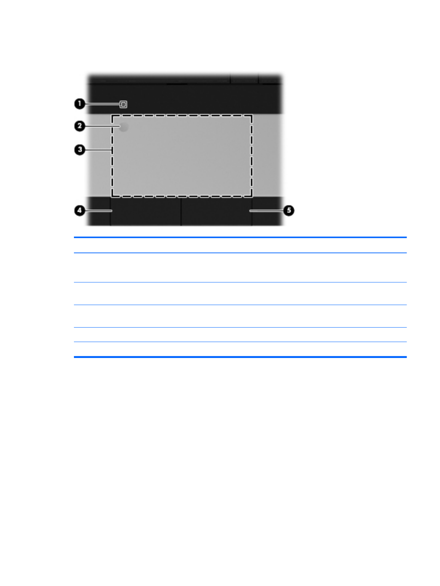
TouchPad
Item Component Description
(1) TouchPad light ●Amber: The TouchPad is off.
●On: The TouchPad is on.
(2) TouchPad on/off button Turns the TouchPad on and off. Quickly double-tap the
TouchPad on/off button to turn the TouchPad on and off.
(3) TouchPad zone Moves the pointer and selects or activates items on
the screen.
(4) Left TouchPad button Functions like the left button on an external mouse.
(5) Right TouchPad button Functions like the right button on an external mouse.
TouchPad 11

Left side
Item Component Description
(1) External monitor port Connects an external VGA monitor or projector.
(2) Vents (2) Enable airflow to cool internal components.
NOTE: The computer fan starts up automatically to cool
internal components and prevent overheating. It is normal
for the internal fan to cycle on and off during
routine operation.
(3) RJ-45 (network) jack Connects a network cable.
(4) HDMI port (select models only) Connects an optional video or audio device, such as a
high-definition television, or any compatible digital or
audio component.
(5) USB port Connect optional USB devices.
(6) Audio-in (microphone) jack Connects an optional computer headset microphone,
stereo array microphone, or monaural microphone.
(7) Audio-out (headphone) jack Produce sound when connected to optional powered
stereo speakers, headphones, ear buds, a headset, or
television audio.
WARNING! To reduce the risk of personal injury,
adjust the volume before putting on headphones,
earbuds, or a headset. For additional safety information,
refer to the Regulatory, Safety, and
Environmental Notices.
When a device is connected to the jack, the computer
speakers are disabled.
(8) Digital Media Slot Supports the following digital card formats:
●MultiMediaCard
●Secure Digital (SD) Memory Card
●Secure Digital High Capacity (SDHC) Memory Card
(9) Drive light Blinking white: The hard drive is being accessed.
(10) Power light ●White: The computer is on.
●Blinking white: The computer is in the Sleep state.
●Off: The computer is off.
12 Chapter 2 External component identification

Right side
Item Component Description
(1) Optical drive (select models only) Reads and writes to an optical disc.
(2) Optical drive light ●On: The optical drive is in use.
●Off: The optical drive is idle.
(3) USB ports (2) Connect optional USB devices.
(4) Power connector Connects an AC adapter.
(5) AC adapter light ●White: The computer is connected to external power
and the battery is fully charged.
●Amber: A battery is charging.
(6) Security cable slot Attaches an optional security cable to the computer.
NOTE: The security cable is designed to act as a
deterrent, but it may not prevent the computer from being
mishandled or stolen.
Right side 13

Bottom
Item Component Description
(1) Battery bay Holds the battery.
(2) Battery release latch Releases the battery from the battery bay.
(3) Vents (5) Enable airflow to cool internal components.
NOTE: The computer fan starts up automatically to cool
internal components and prevent overheating. It is normal
for the internal fan to cycle on and off during
routine operation.
(4) Hard drive bay Holds the hard drive.
(5) Memory module compartment Contains the memory module slots.
14 Chapter 2 External component identification

3 Illustrated parts catalog
Service tag
When ordering parts or requesting information, provide the computer serial number and model
description provided on the service tag.
Item Component Description
(1) Product name This is the product name affixed to the front of
the computer.
(2) Serial number (s/n) This is an alphanumeric identifier that is unique to
each product.
Service tag 15

Item Component Description
(3) Part number/Product number (p/n) This number provides specific information about the
product’s hardware components. The part number helps
a service technician determine what components and
parts are needed.
(4) Warranty period This number describes the duration of the warranty
period for the computer.
(5) Model description This is the alphanumeric identifier used to locate
documents, drivers, and support for the computer.
16 Chapter 3 Illustrated parts catalog

Computer major components
Item Component Spare part number
(1) 15.6-in, high definition (HD), light-emitting diode (LED), BrightView display assembly (includes
microphone and wireless antenna transceivers and cables):
Equipped with webcam 645095-001
Not equipped with webcam 645094-001
NOTE: For more display assembly spare part information, see Display assembly subcomponents on page 23.
Computer major components 17

Item Component Spare part number
(2) Keyboard (includes keyboard cable):
For use with all computer models:
For use in Belgium 646125-A41
For use in Bulgaria 646125-261
For use in Canada 646125-121
For use in the Czech Republic 646125-221
For use in Denmark, Finland, and Norway 646125-DH1
For use in France 646125-051
For use in Germany 646125-041
For use in Greece 646125-DJ1
For use in Hungary 646125-211
For use in Israel 646125-BB1
For use in Italy 646125-061
For use in Latin America 646125-161
For use in the Netherlands 646125-B31
For use in Portugal 646125-131
For use in Russia 646125-251
For use in Saudi Arabia 646125-171
For use in Slovenia 646125-BA1
For use in Spain 646125-071
For use in Switzerland 646125-BG1
For use in Turkey 646125-141
For use in the United Kingdom 646125-031
For use in the United States 646125-001
For use only with computer models equipped with an Intel processor:
For use in India 646125-D61
For use in Japan 646125-291
For use in South Korea 646125-AD1
For use in Taiwan 646125-AB1
(3) Top cover (includes TouchPad and TouchPad cable) 646136-001
(4) Power button board (includes cable) 646129-001
(5) TouchPad button board (includes bracket and cable) 646130-001
18 Chapter 3 Illustrated parts catalog

Item Component Spare part number
Cable Kit, includes: 646119-001
(6a) TouchPad cable
(6b) Optical drive connector cable
(6c) Hard drive connector cable
NOTE: See Cable Kit on page 22 for more Cable Kit spare part information.
(7) USB board (includes cable) 646128-001
(8) Power connector cable 646121-001
Plastics Kit, includes: 646131-001
(9a) Hard drive compartment cover (includes one captive screw, secured by a C-clip)
(9b) Memory module/wireless module compartment cover (includes one captive screw, secured by a C-clip)
NOTE: See Plastics Kit on page 26 for more Plastics Kit spare part information.
(10) Speaker Kit (includes left and right speakers and cable) 647315-001
(11) System board (includes replacement thermal material):
For use only with computer models equipped with an AMD E450 1.65-GHz processor
(dual core, 18 W) and a graphics subsystem with UMA video memory
657323-001
For use only with computer models equipped with an AMD E350 1.60-GHz processor
(dual core, 18 W) and a graphics subsystem with UMA video memory (for use only
with computer models in the United States)
647320-001
For use only with computer models equipped with an AMD E300 1.30-GHz processor
(dual core, 18 W) and a graphics subsystem with UMA video memory
657324-001
For use only with computer models equipped with an AMD C50 1.00-GHz processor
(1.0-MB L2 cache, dual core, 9 W) and a graphics subsystem with UMA
video memory (for use only with computer models in the United States)
653985-001
For use only with computer models equipped with an Intel Core i5 or i3 processor and
a graphics subsystem with discrete video memory
646179-001
For use only with computer models equipped with an Intel Core i5 or i3 processor and
a graphics subsystem with UMA video memory
646177-001
For use only with computer models equipped with an Intel Pentium processor and a
graphics subsystem with discrete video memory
646176-001
For use only with computer models equipped with an Intel Pentium processor and a
graphics subsystem with UMA video memory
646175-001
For use only with computer models equipped with an Intel Celeron processor 646174-001
Thermal Material Kit (includes replacement thermal paste and pads):
For use only with computer models equipped with an AMD processor 650277-001
For use only with computer models equipped with an Intel processor 646135-001
(12) RTC battery (includes cable and double-sided tape) 646132-001
(13) Processor (includes replacement thermal material):
Computer major components 19

Item Component Spare part number
Intel Core i5-2430M 2.40-GHz processor (1333-MHz FSB, 3.0-MB L3 cache,
dual core, 35 W; not supported on computer models equipped with Windows 7
Starter 32-bit operating system)
653341-001
Intel Core i3-2330M 2.20-GHz processor (1333-MHz FSB, 3.0-MB L3 cache,
dual core, 35 W; not supported on computer models equipped with Windows 7
Starter 32-bit operating system)
653339-001
Intel Core i3-370M 2.40-GHz processor (1066-MHz FSB, 3.0-MB L3 cache,
dual core, 35 W; not supported on computer models equipped with Windows 7
Starter 32-bit operating system)
613584-001
Intel Pentium P6300 2.26-GHz processor (3.0-MB L3 cache, dual core, 35 W) 635500-001
Intel Pentium P6200 2.13-GHz processor (3.0-MB L3 cache, dual core, 35 W) 625831-001
Intel Pentium B960 2.20-GHz processor (2.0-MB L2 cache, dual core, TJ85, 35 W;
not supported on computer models equipped with Windows 7 Starter 32-bit
operating system)
664662-001
Intel Pentium B950 2.10-GHz processor (2.0-MB L2 cache, dual core, TJ85, 35 W;
not supported on computer models equipped with Windows 7 Starter 32-bit
operating system)
653338-001
Intel Celeron B800 1.50-GHz processor (2.0-MB L3 cache, dual core, 35 W) 664661-001
Intel Celeron B710 1.50-GHz processor (1.0-MB L3 cache, single core, 35 W) 664660-001
Intel Celeron DC T3500 2.10-GHz processor (1.0-MB L2 cache, 800-MHz FSB) 625830-001
Intel Celeron DC T3300 2.00-GHz processor (1.0-MB L2 cache, 800-MHz FSB) 592399-001
Intel Celeron SC C925 2.30-GHz processor (1.0-MB L2 cache, 800-MHz FSB) 636636-001
Intel Celeron SC C900 2.20-GHz processor (1.0-MB L2 cache, 800-MHz FSB) 534419-001
(14) Fan/heat sink assembly (includes replacement thermal material):
For use only with computer models equipped with an AMD processor 647316-001
For use only with computer models equipped with an Intel Core i5 or i3 processor and
a graphics subsystem with discrete video memory
646182-001
For use only with computer models equipped with an Intel Core i5 or i3 processor and
a graphics subsystem with UMA video memory
646183-001
For use only with computer models equipped with an Intel Pentium processor and a
graphics subsystem with discrete video memory
646180-001
For use only with computer models equipped with an Intel Pentium processor and a
graphics subsystem with UMA video memory
646181-001
For use only with computer models equipped with an Intel Celeron processor and a
graphics subsystem with UMA video memory
646184-001
(15) Base enclosure (includes battery release latch, heat sink,
replacement thermal material, and 4 rubber feet)
646114-001
(16) Battery:
6-cell, 55-Whr, 2.55-Ah Li-ion battery 593554-001
20 Chapter 3 Illustrated parts catalog

Item Component Spare part number
6-cell, 47-Whr, 2.20-Ah Li-ion battery 593553-001
(17) Optical drive (select models only; includes bezel and bracket):
DVD±RW and CD-RW Super Multi Double-Layer Combo Drive with LightScribe 646126-001
DVD±RW and CD-RW Drive 659879-001
DVD-ROM Drive 659638-001
Optical drive slot space saver 659632-001
(18) Hard drive (2.5-in, 7.0-mm, SATA; does not include hard drive connector cable, hard drive bracket, or screws):
500-GB, 5400-rpm 634932-001
320-GB, 5400-rpm 622643-001
250-GB, 5400-rpm 622641-001
Hard Drive Hardware Kit (not illustrated, includes hard drive bracket and screws) 646122-001
(19) Memory modules (2, PC3, 10600, 1333-MHz):
4 GB 621569-001
2 GB 621565-001
1 GB 639738-001
(20) WLAN module:
Atheros 9485GN 802.11b/g/n 1×1 WiFi and 3012 Bluetooth 4.0 Combo Adapter 655795-001
Atheros AR9002WB-1NGB 802.11b/g/n 1×1 WiFi and Bluetooth 2.1+EDR
Combo Adapter (BT3.0+HS ready)
593127-001
Broadcom 4313GN 802.11b/g/n 1×1 WiFi and 20702 Bluetooth 4.0
Combo Adapter
657325-001
Ralink 5390GN 802.11b/g/n 1×1 WiFi Adapter 630703-001
Realtek 8188BC8 802.11a/b/g/n 2×2 WiFi and Bluetooth 3.0+HS Combo Adapter 602993-001
Realtek 8188GN 802.11b/g/n 1×1 WiFi Adapter 640926-001
Computer major components 21

Cable Kit
Item Component Spare part number
Cable Kit, includes: 646119-001
(1) TouchPad cable
(2) Optical drive connector cable
(3) Hard drive connector cable
22 Chapter 3 Illustrated parts catalog

Display assembly subcomponents
Item Component Spare part number
(1) Display bezel:
For use with computer models equipped with a webcam and a microphone 646117-001
For use with computer models equipped only with a microphone 646118-001
(2) Display hinge covers (2) 646124-001
(3) 15.6-in, HD, LED, BrightView display panel 645096-001
(4) Webcam/microphone module 646138-001
Microphone module 645980-001
(5) Display Hinge Kit (includes left and right display hinges and brackets) 646123-001
(6) Display Cable Kit (includes display panel cable and webcam/
microphone module cable)
646120-001
(7) Antenna Kit (includes left and right wireless antenna cables and transceivers) 646111-001
Display assembly subcomponents 23

Item Component Spare part number
(8) Display enclosure 646113-001
Display Screw Kit (not illustrated, includes Mylar screw covers and screws) 646134-001
Mass storage devices
Item Component Spare part number
(1) Hard drive (2.5-in, 7.0-mm, SATA; does not include hard drive connector cable, hard drive bracket, or screws):
500-GB, 5400-rpm 634932-001
320-GB, 5400-rpm 622643-001
250-GB, 5400-rpm 622641-001
Hard Drive Hardware Kit, includes: 646122-001
(2) Hard drive bracket
Screws (not illustrated)
(3) Optical drive (includes bezel and bracket):
DVD±RW and CD-RW Super Multi Double-Layer Combo Drive with LightScribe
(select models only)
646126-001
DVD±RW and CD-RW Drive 659879-001
24 Chapter 3 Illustrated parts catalog

Item Component Spare part number
DVD-ROM Drive 659638-001
Optical drive slot space saver 659632-001
Miscellaneous parts
Component Spare part number
HP Smart AC adapter:
65-W RC V HP Smart AC adapter for use will all computer models 609939-001
For use only with computer models equipped with an Intel processor:
90-W PFC RC V EM HP Smart AC adapter 609940-001
90-W PFC RC V HP Smart AC adapter 609947-001
65-W RC V EM HP Smart AC adapter 609948-001
Power cord (3-pin, black, 1.83-m):
For use with all computer models:
For use in Argentina 490371-D01
For use in Denmark 490371-081
For use in Europe 490371-021
For use in Italy 490371-061
For use in Israel 490371-BB1
For use in North America 490371-001
For use in South Africa 490371-AR1
For use in Switzerland 490371-111
For use in the United Kingdom and Singapore 490371-031
For use only with computer models equipped with an Intel processor:
For use in Australia 490371-011
For use in India 490371-D61
For use in Italy 490371-061
For use in Japan 490371-291
For use in the People's Republic of China 490371-AA1
For use in South Korea 490371-AD1
Screw Kit 646133-001
Miscellaneous parts 25

Plastics Kit
Item Component Spare part number
Plastics Kit, includes: 646131-001
(1) Hard drive compartment cover (includes one captive screw, secured by a C-clip)
(2) Memory module/wireless module compartment cover (includes one captive screw, secured by a C-clip)
26 Chapter 3 Illustrated parts catalog

Sequential part number listing
Spare part number Description
490371-001 Power cord for use with all computer models in North America (3-pin, black, 1.83-m)
490371-011 Power cord for use only with computer models equipped with an Intel processor in Australia (3-
pin, black, 1.83-m)
490371-021 Power cord for use with all computer models in Europe (3-pin, black, 1.83-m)
490371-031 Power cord for use with all computer models in the United Kingdom and Singapore (3-
pin, black, 1.83-m)
490371-061 Power cord for use only with computer models equipped with an Intel processor in Italy (3-
pin, black, 1.83-m)
490371-081 Power cord for use with all computer models in Denmark (3-pin, black, 1.83-m)
490371-111 Power cord for use with all computer models in Switzerland (3-pin, black, 1.83-m)
490371-291 Power cord for use only with computer models equipped with an Intel processor in Japan (3-
pin, black, 1.83-m)
490371-AA1 Power cord for use only with computer models equipped with an Intel processor in the People's
Republic of China (3-pin, black, 1.83-m)
490371-AD1 Power cord for use only with computer models equipped with an Intel processor in South Korea (3-
pin, black, 1.83-m)
490371-AR1 Power cord for use with all computer models in South Africa (3-pin, black, 1.83-m)
490371-BB1 Power cord for use with all computer models in Israel (3-pin, black, 1.83-m)
490371-D01 Power cord for use with all computer models in Argentina (3-pin, black, 1.83-m)
490371-D61 Power cord for use only with computer models equipped with an Intel processor in India (3-
pin, black, 1.83-m)
534419-001 Intel Celeron SC C900 2.20-GHz processor (1.0-MB L2 cache, 800-MHz FSB; includes replacement
thermal material)
592399-001 Intel Celeron DC T3300 2.00-GHz processor (1.0-MB L2 cache, 800-MHz FSB; includes
replacement thermal material)
593127-001 Atheros AR9002WB-1NGB 802.11b/g/n 1×1 WiFi and Bluetooth 2.1+EDR Combo Adapter
(BT3.0+HS ready)
593553-001 6-cell, 47-Whr, 2.20-Ah Li-ion battery
593554-001 6-cell, 55-Whr, 2.55-Ah Li-ion battery
602993-001 Realtek 8188BC8 802.11a/b/g/n 2×2 WiFi and Bluetooth 3.0+HS Combo Adapter
609939-001 65-W RC V HP Smart AC adapter for use will all computer models
609940-001 90-W PFC RC V EM HP Smart AC adapter for use only with computer models equipped with an
Intel processor
609947-001 90-W PFC RC V HP Smart AC adapter for use only with computer models equipped with an
Intel processor
Sequential part number listing 27

Spare part number Description
609948-001 65-W RC V EM HP Smart AC adapter for use only with computer models equipped with an
Intel processor
613584-001 Intel Core i3-370M 2.40-GHz processor (1066-MHz FSB, 3.0-MB L3 cache, dual core, 35 W;
includes replacement thermal material; not supported on computer models equipped with
Windows 7 Starter 32-bit operating system)
621565-001 2-GB memory module (PC3, 10600, 1333-MHz)
621569-001 4-GB memory module (PC3, 10600, 1333-MHz)
622641-001 250-GB, 5400-rpm hard drive (2.5-in, 7.0-mm, SATA; does not include hard drive connector cable,
hard drive bracket, or screws)
622643-001 320-GB, 5400-rpm hard drive (2.5-in, 7.0-mm, SATA; does not include hard drive connector cable,
hard drive bracket, or screws)
625830-001 Intel Celeron DC T3500 2.10-GHz processor (1.0-MB L2 cache, 800-MHz FSB; includes
replacement thermal material)
625831-001 Intel Pentium P6200 2.13-GHz processor (3.0-MB L3 cache, dual core, 35 W; includes replacement
thermal material)
630703-001 Ralink 5390GN 802.11b/g/n 1×1 WiFi Adapter
634932-001 500-GB, 5400-rpm hard drive (2.5-in, 7.0-mm, SATA; does not include hard drive connector cable,
hard drive bracket, or screws)
635500-001 Intel Pentium P6300 2.26-GHz processor (3.0-MB L3 cache, dual core, 35 W; includes replacement
thermal material)
636636-001 Intel Celeron SC C925 2.30-GHz processor (1.0-MB L2 cache, 800-MHz FSB; includes replacement
thermal material)
639738-001 1-GB memory module (PC3, 10600, 1333-MHz)
640926-001 Realtek 8188GN 802.11b/g/n 1×1 WiFi Adapter
645094-001 15.6-in, HD, LED, BrightView display assembly not equipped with a webcam (includes microphone
and wireless antenna transceivers and cables)
645095-001 15.6-in, HD, LED, BrightView display assembly equipped with a webcam (includes microphone and
wireless antenna transceivers and cables)
645096-001 15.6-in, HD, LED, BrightView display panel
645980-001 Microphone module
646111-001 Antenna Kit (includes left and right wireless antenna cables and transceivers)
646113-001 Display enclosure
646114-001 Base enclosure (includes battery release latch, heat sink, replacement thermal material,
and 4 rubber feet)
646117-001 Display bezel for use with computer models equipped with a webcam and a microphone
646118-001 Display bezel for use with computer models equipped only with a microphone
646119-001 Cable Kit (includes TouchPad cable, optical drive connector cable, and hard drive connector cable)
NOTE: See Cable Kit on page 22 for more Cable Kit spare part information.
28 Chapter 3 Illustrated parts catalog

Spare part number Description
646120-001 Display Cable Kit (includes display panel cable and webcam/microphone module cable)
646121-001 Power connector cable
646122-001 Hard Drive Hardware Kit (includes hard drive bracket and screws)
646123-001 Display Hinge Kit (includes left and right display hinges and brackets)
646124-001 Display hinge covers
646125-001 Keyboard for use with all computer models in the United States (includes keyboard cable)
646125-031 Keyboard for use with all computer models in the United Kingdom and Singapore (includes
keyboard cable)
646125-041 Keyboard for use with all computer models in Germany (includes keyboard cable)
646125-051 Keyboard for use with all computer models in France (includes keyboard cable)
646125-061 Keyboard for use with all computer models in Italy (includes keyboard cable)
646125-071 Keyboard for use with all computer models in Spain (includes keyboard cable)
646125-121 Keyboard for use with all computer models in Canada (includes keyboard cable)
646125-131 Keyboard for use with all computer models in Portugal (includes keyboard cable)
646125-141 Keyboard for use with all computer models in Turkey (includes keyboard cable)
646125-161 Keyboard for use with all computer models in Latin America (includes keyboard cable)
646125-171 Keyboard for use with all computer models in Saudi Arabia (includes keyboard cable)
646125-211 Keyboard for use with all computer models in Hungary (includes keyboard cable)
646125-221 Keyboard for use with all computer models in the Czech Republic (includes keyboard cable)
646125-251 Keyboard for use with all computer models in Russia (includes keyboard cable)
646125-261 Keyboard for use with all computer models in Bulgaria (includes keyboard cable)
646125-291 Keyboard for use only with computer models equipped with an Intel processor in Japan (includes
keyboard cable)
646125-A41 Keyboard for use with all computer models in Belgium (includes keyboard cable)
646125-AB1 Keyboard for use only with computer models equipped with an Intel processor in Taiwan (includes
keyboard cable)
646125-AD1 Keyboard for use only with computer models equipped with an Intel processor in South Korea
(includes keyboard cable)
646125-B31 Keyboard for use with all computer models in the Netherlands (includes keyboard cable)
646125-BA1 Keyboard for use with all computer models in Slovenia (includes keyboard cable)
646125-BB1 Keyboard for use with all computer models in Israel (includes keyboard cable)
646125-BG1 Keyboard for use with all computer models in Switzerland (includes keyboard cable)
646125-D61 Keyboard for use only with computer models equipped with an Intel processor in India (includes
keyboard cable)
Sequential part number listing 29

Spare part number Description
646125-DH1 Keyboard for use with all computer models in Denmark, Finland, and Norway (includes
keyboard cable)
646125-DJ1 Keyboard for use with all computer models in Greece (includes keyboard cable)
646126-001 DVD±RW and CD-RW Super Multi Double-Layer Combo Drive with LightScribe (select models only)
646128-001 USB board (includes cable)
646129-001 Power button board (includes cable)
646130-001 TouchPad button board (includes bracket and cable)
646131-001 Plastics Kit (includes hard drive compartment cover and memory module/wireless module
compartment cover)
NOTE: See Plastics Kit on page 26 for more Plastics Kit spare part information.
646132-001 RTC battery (includes cable and double-sided tape)
646133-001 Screw Kit
646134-001 Display Screw Kit (includes Mylar screw covers and screws)
646135-001 Thermal Material Kit for use only with computer models equipped with an Intel processor (includes
replacement thermal paste and pads)
646136-001 Top cover (includes TouchPad and TouchPad cable)
646138-001 Webcam/microphone module
646174-001 System board for use only with computer models equipped with an Intel Celeron processor (includes
replacement thermal material)
646175-001 System board for use only wi an Intel Pentium processor and ath computer models equipped with
graphics subsystem with UMA video memory (includes replacement thermal material)
646176-001 System board for use only wi an Intel Pentium processor and ath computer models equipped with
graphics subsystem with discrete video memory (includes replacement thermal material)
646177-001 System board for use only with computer models equipped with an Intel Core i5 or i3 processor and
a graphics subsystem with UMA video memory (includes replacement thermal material)
646179-001 System board for use only with computer models equipped with an Intel Core i5 or i3 processor and
a graphics subsystem with discrete video memo ent thermal material)ry (includes replacem
646180-001 Fan/heat sink assembly for use only with computer models equipped with an Intel Pentium processor
and a graphics subsystem with discrete video memory (includes replacement thermal material)
646181-001 Fan/heat sink assembly for use only with computer models equipped with an Intel Pentium processor
and a graphics subsystem with UMA video memory (includes replacement thermal material)
646182-001 Fan/heat sink assembly for use only with computer models equipped with an Intel Core i5 or i3
processor and a graphics subsystem with discrete video memory (includes replacement
thermal material)
646183-001 Fan/heat sink assembly for use only with computer models equipped with an Intel Core i5 or i3
processor and a graphics subsystem with UMA video memory (includes replacement
thermal material)
646184-001 Fan/heat sink assembly for use only with computer models equipped with an Intel Celeron processor
and a graphics subsystem with UMA video memory (includes replacement thermal material)
30 Chapter 3 Illustrated parts catalog

4 Removal and replacement
procedures
Preliminary replacement requirements
Tools required
You will need the following tools to complete the removal and replacement procedures:
●Flat-bladed screwdriver
●Magnetic screwdriver
●Phillips P0 and P1 screwdrivers
Service considerations
The following sections include some of the considerations that you must keep in mind during
disassembly and assembly procedures.
NOTE: As you remove each subassembly from the computer, place the subassembly (and all
accompanying screws) away from the work area to prevent damage.
Plastic parts
CAUTION: Using excessive force during disassembly and reassembly can damage plastic parts. Use
care when handling the plastic parts. Apply pressure only at the points designated in the
maintenance instructions.
Cables and connectors
CAUTION: When servicing the computer, be sure that cables are placed in their proper locations
during the reassembly process. Improper cable placement can damage the computer.
Cables must be handled with extreme care to avoid damage. Apply only the tension required to unseat
or seat the cables during removal and insertion. Handle cables by the connector whenever possible. In
all cases, avoid bending, twisting, or tearing cables. Be sure that cables are routed in such a way that
they cannot be caught or snagged by parts being removed or replaced. Handle flex cables with
extreme care; these cables tear easily.
32 Chapter 4 Removal and replacement procedures

Drive handling
CAUTION: Drives are fragile components that must be handled with care. To prevent damage to the
computer, damage to a drive, or loss of information, observe these precautions:
Before removing or inserting a hard drive, shut down the computer. If you are unsure whether the
computer is off or in Hibernation, turn the computer on, and then shut it down through the
operating system.
Before handling a drive, be sure that you are discharged of static electricity. While handling a drive,
avoid touching the connector.
Before removing a diskette drive or optical drive, be sure that a diskette or disc is not in the drive and
be sure that the optical drive tray is closed.
Handle drives on surfaces covered with at least one inch of shock-proof foam.
Avoid dropping drives from any height onto any surface.
After removing a hard drive, an optical drive, or a diskette drive, place it in a static-proof bag.
Avoid exposing an internal hard drive to products that have magnetic fields, such as monitors
or speakers.
Avoid exposing a drive to temperature extremes or liquids.
If a drive must be mailed, place the drive in a bubble pack mailer or other suitable form of protective
packaging and label the package “FRAGILE.”
Grounding guidelines
Electrostatic discharge damage
Electronic components are sensitive to electrostatic discharge (ESD). Circuitry design and structure
determine the degree of sensitivity. Networks built into many integrated circuits provide some
protection, but in many cases, ESD contains enough power to alter device parameters or melt
silicon junctions.
A discharge of static electricity from a finger or other conductor can destroy static-sensitive devices or
microcircuitry. Even if the spark is neither felt nor heard, damage may have occurred.
An electronic device exposed to ESD may not be affected at all and can work perfectly throughout a
normal cycle. Or the device may function normally for a while, then degrade in the internal layers,
reducing its life expectancy.
Preliminary replacement requirements 33

Equipment guidelines
Grounding equipment must include either a wrist strap or a foot strap at a grounded workstation.
●When seated, wear a wrist strap connected to a grounded system. Wrist straps are flexible straps
with a minimum of one megohm ±10% resistance in the ground cords. To provide proper ground,
wear a strap snugly against the skin at all times. On grounded mats with banana-plug connectors,
use alligator clips to connect a wrist strap.
●When standing, use foot straps and a grounded floor mat. Foot straps (heel, toe, or boot straps)
can be used at standing workstations and are compatible with most types of shoes or boots. On
conductive floors or dissipative floor mats, use foot straps on both feet with a minimum of one
megohm resistance between the operator and ground. To be effective, the conductive must be
worn in contact with the skin.
The following grounding equipment is recommended to prevent electrostatic damage:
●Antistatic tape
●Antistatic smocks, aprons, and sleeve protectors
●Conductive bins and other assembly or soldering aids
●Nonconductive foam
●Conductive tabletop workstations with ground cords of one megohm resistance
●Static-dissipative tables or floor mats with hard ties to the ground
●Field service kits
●Static awareness labels
●Material-handling packages
●Nonconductive plastic bags, tubes, or boxes
●Metal tote boxes
●Electrostatic voltage levels and protective materials
The following table lists the shielding protection provided by antistatic bags and floor mats.
Material Use Voltage protection level
Antistatic plastics Bags 1,500 V
Carbon-loaded plastic Floor mats 7,500 V
Metallized laminate Floor mats 5,000 V
36 Chapter 4 Removal and replacement procedures

Component replacement procedures
This chapter provides removal and replacement procedures.
There are as many as 75 screws that must be removed, replaced, or loosened when servicing the
computer. Make special note of each screw size and location during removal and replacement.
Service tag
When ordering parts or requesting information, provide the computer serial number and model number
provided on the service tag.
Item Component Description
(1) Product name This is the product name affixed to the front of
the computer.
(2) Serial number (s/n) This is an alphanumeric identifier that is unique to
each product.
(3) Part number/Product number (p/n) This number provides specific information about the
product’s hardware components. The part number helps
a service technician determine what components and
parts are needed.
Component replacement procedures 37

Item Component Description
(4) Warranty period This number describes the duration of the warranty
period for the computer.
(5) Model description This is the alphanumeric identifier used to locate
documents, drivers, and support for the computer.
Computer feet
The computer feet are adhesive-backed rubber pads. There are 4 rubber feet that attach to the base
enclosure in the locations illustrated below.
38 Chapter 4 Removal and replacement procedures

Battery
Description Spare part number
6-cell, 55-Whr, 2.55-Ah Li-ion battery 593554-001
6-cell, 47-Whr, 2.20-Ah Li-ion battery 593553-001
Before disassembling the computer, follow these steps:
1. Shut down the computer. If you are unsure whether the computer is off or in Hibernation, turn the
computer on, and then shut it down through the operating system.
2. Disconnect all external devices connected to the computer.
3. Disconnect the power from the computer by first unplugging the power cord from the AC outlet
and then unplugging the AC adapter from the computer.
Remove the battery:
1. Slide the battery release latch (1) to release the battery.
2. Pivot the front edge of the battery (2) up and back.
3. Remove the battery (3) from the computer.
Component replacement procedures 39

To insert the battery:
1. Align the tabs on the rear edge of the battery with the notches on the rear edge of the battery bay.
2. Pivot the front edge of the battery down into the battery bay until it is seated. (The battery release
latch will automatically lock into place.)
Optical drive (select models only)
NOTE: The optical drive spare part kit includes a bezel and bracket.
Description Spare part number
DVD±RW and CD-RW Super Multi Double-Layer Combo Drive with LightScribe 646126-001
DVD±RW and CD-RW Drive 659879-001
DVD-ROM Drive 659638-001
Optical drive slot space saver 659632-001
Before removing the optical drive, follow these steps:
1. Shut down the computer. If you are unsure whether the computer is off or in Hibernation, turn the
computer on, and then shut it down through the operating system.
2. Disconnect all external devices connected to the computer.
3. Disconnect the power from the computer by first unplugging the power cord from the AC outlet
and then unplugging the AC adapter from the computer.
4. Remove the battery (see Battery on page 39).
Remove the optical drive:
1. Loosen the captive screw (1) that secures the memory module/wireless module compartment cover
to the computer.
40 Chapter 4 Removal and replacement procedures
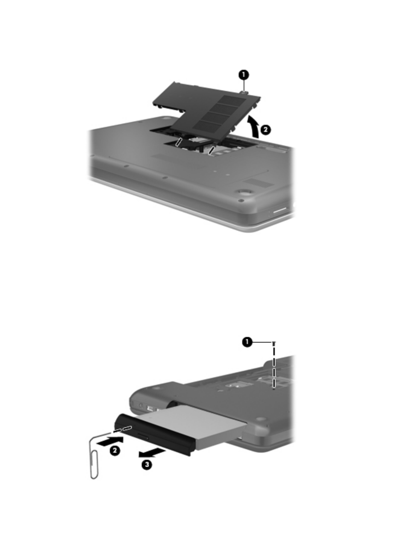
2. Lift the rear edge of the memory module/wireless module compartment cover (2) up and forward
until it rests at an angle.
3. Remove the memory module/wireless module compartment cover. The memory module/
wireless module compartment cover is available in the Plastics Kit, spare part number
646131-001.
4. Remove the Phillips PM2.5×6.0 screw (1) that secures the optical drive to the computer.
5. Insert an unbent paper clip or similar thin tool into the optical drive tab access (2) to release the
optical drive tray from the optical drive.
6. Remove the optical drive (3) by sliding it out of the optical drive bay.
Component replacement procedures 41
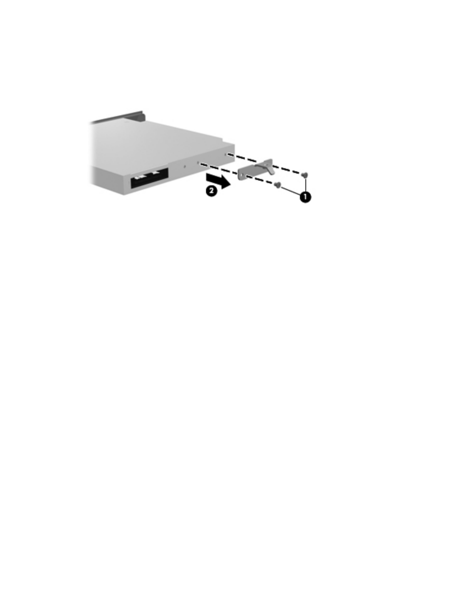
7. If it is necessary to replace the optical drive bracket, position the optical drive with the rear panel
toward you.
8. Remove the two Phillips PM2.0×3.0 screws (1) that secure the bracket to the optical drive.
9. Remove the optical drive bracket (2).
Reverse this procedure to reassemble and install the optical drive.
42 Chapter 4 Removal and replacement procedures

WLAN module
Description Spare part number
Atheros 9485GN 802.11b/g/n 1×1 WiFi and 3012 Bluetooth 4.0 Combo Adapter 655795-001
Atheros AR9002WB-1NGB 802.11b/g/n 1×1 WiFi and Bluetooth 2.1+EDR Combo Adapter
(BT3.0+HS ready)
593127-001
Broadcom 4313GN 802.11b/g/n 1×1 WiFi and 20702 Bluetooth 4.0 Combo Adapter 657325-001
Ralink 5390GN 802.11b/g/n 1×1 WiFi Adapter 630703-001
Realtek 8188BC8 802.11a/b/g/n 2×2 WiFi and Bluetooth 3.0+HS Combo Adapter 602993-001
Realtek 8188GN 802.11b/g/n 1×1 WiFi Adapter 640926-001
CAUTION: To prevent an unresponsive system, replace the wireless module only with a
wireless module authorized for use in the computer by the governmental agency that regulates wireless
devices in your country or region. If you replace the module and then receive a warning message,
remove the module to restore device functionality, and then contact technical support.
Before removing the WLAN module, follow these steps:
1. Shut down the computer. If you are unsure whether the computer is off or in Hibernation, turn the
computer on, and then shut it down through the operating system.
2. Disconnect all external devices connected to the computer.
3. Disconnect the power from the computer by first unplugging the power cord from the AC outlet
and then unplugging the AC adapter from the computer.
4. Remove the battery (see Battery on page 39).
5. Remove the memory module/wireless module compartment cover (see Optical drive (select models
only) on page 40).
Remove the WLAN module:
1. Disconnect the WLAN antenna cables (1) from the terminals on the WLAN module.
NOTE: The #1 WLAN antenna cable is connected to the WLAN module #1 terminal. The #2
WLAN antenna cable is connected to the WLAN module #2 terminal.
2. Remove the Phillips PM2.0×3.0 screw (2) that secures the WLAN module to the system board.
(The WLAN module tilts up.)
Component replacement procedures 43

3. Remove the WLAN module by pulling the module away from the slot at an angle (3).
NOTE: The WLAN module is designed with a notch (4) to prevent incorrect installation into the
WLAN module socket.
NOTE: If the WLAN antennas are not connected to the terminals on the WLAN module, the protective
sleeves must be installed on the antenna connectors, as shown in the following illustration.
Reverse this procedure to install the WLAN module.
44 Chapter 4 Removal and replacement procedures
Memory module
Description Spare part number
4-GB (PC3, 10600, 1333-MHz) 621569-001
2-GB (PC3, 10600, 1333-MHz) 621565-001
1-GB (PC3, 10600, 1333-MHz) 639738-001
Before removing a memory module, follow these steps:
1. Shut down the computer. If you are unsure whether the computer is off or in Hibernation, turn the
computer on, and then shut it down through the operating system.
2. Disconnect all external devices connected to the computer.
3. Disconnect the power from the computer by first unplugging the power cord from the AC outlet
and then unplugging the AC adapter from the computer.
4. Remove the battery (see Battery on page 39).
5. Remove the memory module/wireless module compartment cover (see Optical drive (select models
only) on page 40).
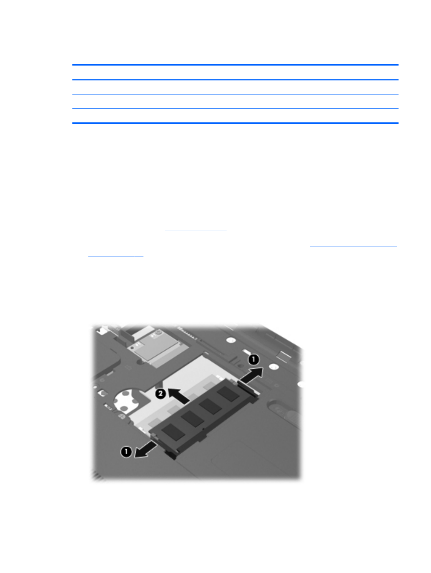
Remove the memory module:
1. Spread the retaining tabs (1) on each side of the memory module slot to release the
memory module. (The memory module tilts up.)
2. Remove the memory module (2) by pulling it away from the slot at an angle.
Reverse this procedure to install a memory module.
Component replacement procedures 45

Hard drive
NOTE: The hard drive spare part kit does not include the hard drive connector cable, bracket, or
screws. The hard drive connector cable is included in the Cable Kit, spare part number 646119-001.
The hard drive bracket and screws are included in the Hard Drive Hardware Kit, spare part number
646122-001.
Description Spare part number
500-GB, 5400-rpm 634932-001
320-GB, 5400-rpm 622643-001
250-GB, 5400-rpm 622641-001
Before removing the hard drive, follow these steps:
1. Shut down the computer. If you are unsure whether the computer is off or in Hibernation, turn the
computer on, and then shut it down through the operating system.
2. Disconnect all external devices connected to the computer.
3. Disconnect the power from the computer by first unplugging the power cord from the AC outlet
and then unplugging the AC adapter from the computer.
4. Remove the battery (see Battery on page 39).
5. Remove the memory module/wireless module compartment cover (see Optical drive (select models
only) on page 40).
Remove the hard drive:
1. Loosen the captive screw (1) that secures the hard drive compartment cover to the computer.
46 Chapter 4 Removal and replacement procedures

2. Lift the rear edge of the hard drive compartment cover (2) up and forward until it rests at
an angle.
3. Remove the hard drive compartment cover. The hard drive compartment cover is available in the
Plastics Kit, spare part number 646131-001.
4. Disconnect the hard drive connector cable (1) from the system board.
5. Release the hard drive connector cable from the clips (2) built into the base enclosure.
6. Remove the four Phillips PM 2.5×6.0 screws (3) that secure the hard drive to the computer.
7. Remove the hard drive (4).
Component replacement procedures 47

8. If it is necessary to replace the hard drive connector cable (1), the hard drive screws , or the(2)
hard drive bracket (3), remove and replace the components.
Reverse this procedure to reassemble and install the hard drive.
48 Chapter 4 Removal and replacement procedures

Remove the keyboard:
1. Remove the Phillips PM2.5×6.0 screw that secures the keyboard to the computer.
2. Rest and secure the computer on its left side.
3. Partially open the computer.
4. Insert a screw driver or similar thin tool into the keyboard release hole, and then press on the back
of the keyboard until the keyboard disengages from the computer.
50 Chapter 4 Removal and replacement procedures

5. Turn the computer right-side up with the front toward you.
6. Lift the rear edge of the keyboard (1) (2), and then swing the keyboard up and forward until it
rests upside down on the palm rest.
7. Release the zero insertion force (ZIF) connector (1) to which the keyboard cable is attached, and
then disconnect the keyboard cable (2) from the system board.
8. Remove the keyboard.
Reverse this procedure to install the keyboard.
Component replacement procedures 51
Top cover
NOTE: The top cover spare part kit includes the TouchPad and TouchPad cable.
Description Spare part number
Top cover (includes TouchPad and TouchPad cable) 646136-001
Before removing the top cover, follow these steps:
1. Shut down the computer. If you are unsure whether the computer is off or in Hibernation, turn the
computer on, and then shut it down through the operating system.
2. Disconnect all external devices connected to the computer.
3. Disconnect the power from the computer by first unplugging the power cord from the AC outlet
and then unplugging the AC adapter from the computer.
4. Remove the battery (see Battery on page 39).
5. Remove the optical drive (see Optical drive (select models only) on page 40).
6. Remove the keyboard (see Keyboard on page 49).
When replacing the top cover, be sure that the following components are removed from the defective
top cover and installed on the replacement top cover:
●Power button board and cable (see Power button board on page 56)
●TouchPad button board and cable (see TouchPad button board on page 57)
Remove the top cover:
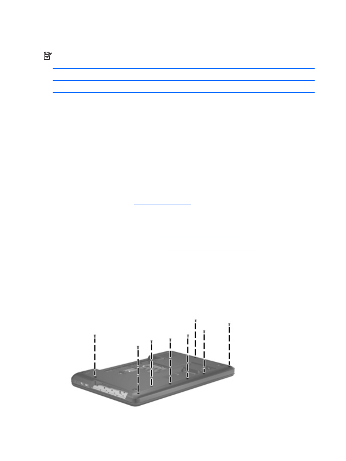
1. Close the computer.
2. Turn the computer upside down, with the front toward you.
3. Remove the eight Phillips PM2.5×6.0 screws on the surface of the base enclosure that secure the
top cover to the computer.
52 Chapter 4 Removal and replacement procedures

11. Remove the top cover (2).
Reverse this procedure to install the top cover.
Component replacement procedures 55

Power button board
Description Spare part number
Power button board (includes cable) 646129-001
Before removing the power button board, follow these steps:
1. Shut down the computer. If you are unsure whether the computer is off or in Hibernation, turn the
computer on, and then shut it down through the operating system.
2. Disconnect all external devices connected to the computer.
3. Disconnect the power from the computer by first unplugging the power cord from the AC outlet
and then unplugging the AC adapter from the computer.
4. Remove the battery (see Battery on page 39), and then remove the following components:
●Optical drive (see Optical drive (select models only) on page 40)
●Keyboard (see Keyboard on page 49)
●Top cover (see Top cover on page 52)
Remove the power button board:
1. Turn the top cover upside down, with the top toward you.
2. Remove the two Phillips PM2.0×3.0 screws (1) that secure the power button board to the
top cover.
3. Remove the power button board and cable (2).
Reverse this procedure to install the power button board and cable.
56 Chapter 4 Removal and replacement procedures

TouchPad button board
Description Spare part number
TouchPad button board (includes cable) 646130-001
Before removing the TouchPad button board, follow these steps:
1. Shut down the computer. If you are unsure whether the computer is off or in Hibernation, turn the
computer on, and then shut it down through the operating system.
2. Disconnect all external devices connected to the computer.
3. Disconnect the power from the computer by first unplugging the power cord from the AC outlet
and then unplugging the AC adapter from the computer.
4. Remove the battery (see Battery on page 39), and then remove the following components:
●Optical drive (see Optical drive (select models only) on page 40)
●Keyboard (see Keyboard on page 49)
●Top cover (see Top cover on page 52)
Remove the TouchPad button board and cable:
1. Turn the top cover upside down, with the top toward you.
2. Release the TouchPad board cable (1) (2) and the TouchPad button board cable from the
top cover. (The TouchPad board cable and the TouchPad button board cable are attached to the
top cover with double-sided tape.)
3. Remove the four Phillips PM2.0×4.0 screws (3) that secure the TouchPad button board to the
top cover.
Component replacement procedures 57

4. Remove the TouchPad button board (4) and cables from the top cover.
Reverse this procedure to install the TouchPad button board and cable.
58 Chapter 4 Removal and replacement procedures

Power connector cable
Description Spare part number
Power connector cable 641394-001
Before removing the power connector cable, follow these steps:
1. Shut down the computer. If you are unsure whether the computer is off or in Hibernation, turn the
computer on, and then shut it down through the operating system.
2. Disconnect all external devices connected to the computer.
3. Disconnect the power from the computer by first unplugging the power cord from the AC outlet
and then unplugging the AC adapter from the computer.
4. Remove the battery (see Battery on page 39), and then remove the following components:
●Optical drive (see Optical drive (select models only) on page 40)
●Keyboard (see Keyboard on page 49)
●Top cover (see Top cover on page 52)
●USB board (see USB board on page 59)
Remove the power connector cable:
1. Close the computer.
2. Turn the computer upside down, with the front toward you.
3. Disconnect the power connector cable (1) from the system board.
4. Release the power connector cable from the clips (2) built into the base enclosure.
60 Chapter 4 Removal and replacement procedures

5. Turn the computer right-side up, with the front toward you.
6. Open the computer.
7. Remove the two Phillips PM2.5×6.0 screws (1) that secure the power connector and bracket to
the computer.
8. Remove the power connector bracket (2).
9. Remove the power connector (3).
Reverse this procedure to install the power connector cable.
Component replacement procedures 61

Speakers
Description Spare part number
Speaker Kit (includes left and right speakers and cable) 647315-001
Before removing the speakers, follow these steps:
1. Shut down the computer. If you are unsure whether the computer is off or in Hibernation, turn the
computer on, and then shut it down through the operating system.
2. Disconnect all external devices connected to the computer.
3. Disconnect the power from the computer by first unplugging the power cord from the AC outlet
and then unplugging the AC adapter from the computer.
4. Remove the battery (see Battery on page 39), and then remove the following components:
●Optical drive (see Optical drive (select models only) on page 40)
●Keyboard (see Keyboard on page 49)
●Top cover (see Top cover on page 52)
●USB board (see USB board on page 59)
Remove the speakers:
1. Disconnect the speaker cable (1) from the system board.
2. Release the speaker cables (2) from the clips built into the base enclosure. Remove the Phillips
PM2.5×9.0 screw (3) and the three Phillips PM2.5×6.0 screws (4) that secure the speakers to the
computer. Remove the speakers (5).
62 Chapter 4 Removal and replacement procedures

6. If it is necessary to replace the webcam/microphone module or microphone module:
a. Detach and release the module (1) as far as the module cable allows. (The module is
attached to the display enclosure with double-sided tape.)
b. Disconnect the module cable (2) from the module.
c. Remove the webcam/microphone module (3) or microphone module. The webcam/
microphone module is available using spare part number 646138-001. The
microphone module is available using spare part number 645980-001.
7. If it is necessary to replace the hinge covers:
a. Remove the two Phillips PM2.5×5.0 (1) screws that secure the hinge covers to the
display enclosure.
66 Chapter 4 Removal and replacement procedures

b. Remove the hinge covers (2). The hinge covers are available using spare part number
646124-001.
8. If it is necessary to replace the display panel:
a. Remove the two Phillips PM2.5×4.0 screws (1) and four Phillips PM2.5×5.0 screws (2) that
secure the display panel to the display enclosure.
Component replacement procedures 67

b. Lift the top edge of the display panel, and then swing it up and forward until it rests upside
down in front of the display enclosure.
c. Release the adhesive strip (1) that secures the display panel cable to the display panel, and
then disconnect the display panel cable (2) from the display panel.
d. Remove the display panel. The display panel is available using spare part number
645096-001.
9. If it is necessary to replace the display hinges:
a. Remove the four Phillips PM2.0×3.0 screws (1) that secure the display hinges to the
display panel.
68 Chapter 4 Removal and replacement procedures

b. Remove the display hinges (2). The display hinges include the display hinges and brackets
and are available using spare part number 646123-001.
10. If it is necessary to replace the display panel cable:
a. Release the tabs (1) built into the display enclosure shielding that secure the display panel
cable to the display enclosure.
b. Release the display panel cable from the clips (2) built into the display enclosure.
c. Remove the display panel cable (3). The display panel cable includes the webcam/
microphone module cable and is available in the Display Cable Kit, spare part number
646120-001.
Component replacement procedures 69

11. If it is necessary to replace the wireless antenna cable and transceiver:
a. Release the wireless antenna transceiver (1) from the display enclosure. (The wireless
antenna transceiver is attached to the display enclosure with double-sided tape.)
b. Release the wireless antenna cable from the clips (2) built into the display enclosure.
c. Remove the wireless antenna cable and transceiver (3). The wireless antenna cable and
transceiver are available in the Antenna Kit, spare part number 646111-001.
Reverse this procedure to reassemble and install the display assembly.
70 Chapter 4 Removal and replacement procedures

System board
NOTE: The system board spare part kit includes replacement thermal material.
Replacement thermal material is also available in the Thermal Material Kit, spare part numbers
650277-001 (for use only with computer models equipped with an AMD processor) and 646135-001
(for use only with computer models equipped with an Intel processor).
Description Spare part number
For use only with computer models equipped with an AMD E450 1.65-GHz processor (dual core,
18 W) and a graphics subsystem with UMA video memory
657323-001
For use only with computer models equipped with an AMD E350 1.60-GHz processor (dual core,
18 W) and a graphics subsystem with UMA video memory (for use only with computer models in the
United States)
647320-001
For use only with computer models equipped with an AMD E300 1.30-GHz processor (dual core,
18 W) and a graphics subsystem with UMA video memory
657324-001
For use only with computer models equipped with an AMD C50 1.00-GHz processor (1.0-
MB L2 cache, dual core, 9 W) and a graphics subsystem with UMA video memory (for use only with
computer models in the United States)
653985-001
For use only with computer models equipped with an Intel Core i5 or i3 processor and a graphics
subsystem with discrete video memory
646179-001
For use only with computer models equipped with an Intel Core i5 or i3 processor and a graphics
subsystem with UMA video memory
646177-001
For use only with computer models equipped with an Intel Pentium processor and a graphics
subsystem with discrete video memory
646176-001
For use only with computer models equipped with an Intel Pentium processor and a graphics
subsystem with UMA video memory
646175-001
For use only with computer models equipped with an Intel Celeron processor 646174-001
Before removing the system board, follow these steps:
1. Shut down the computer. If you are unsure whether the computer is off or in Hibernation, turn the
computer on, and then shut it down through the operating system.
2. Disconnect all external devices connected to the computer.
3. Disconnect the power from the computer by first unplugging the power cord from the AC outlet
and then unplugging the AC adapter from the computer.
4. Remove the battery (see Battery on page 39).
5. Remove the optical drive (see Optical drive (select models only) on page 40).
6. Remove the WLAN module (see WLAN module on page 43).
Component replacement procedures 71
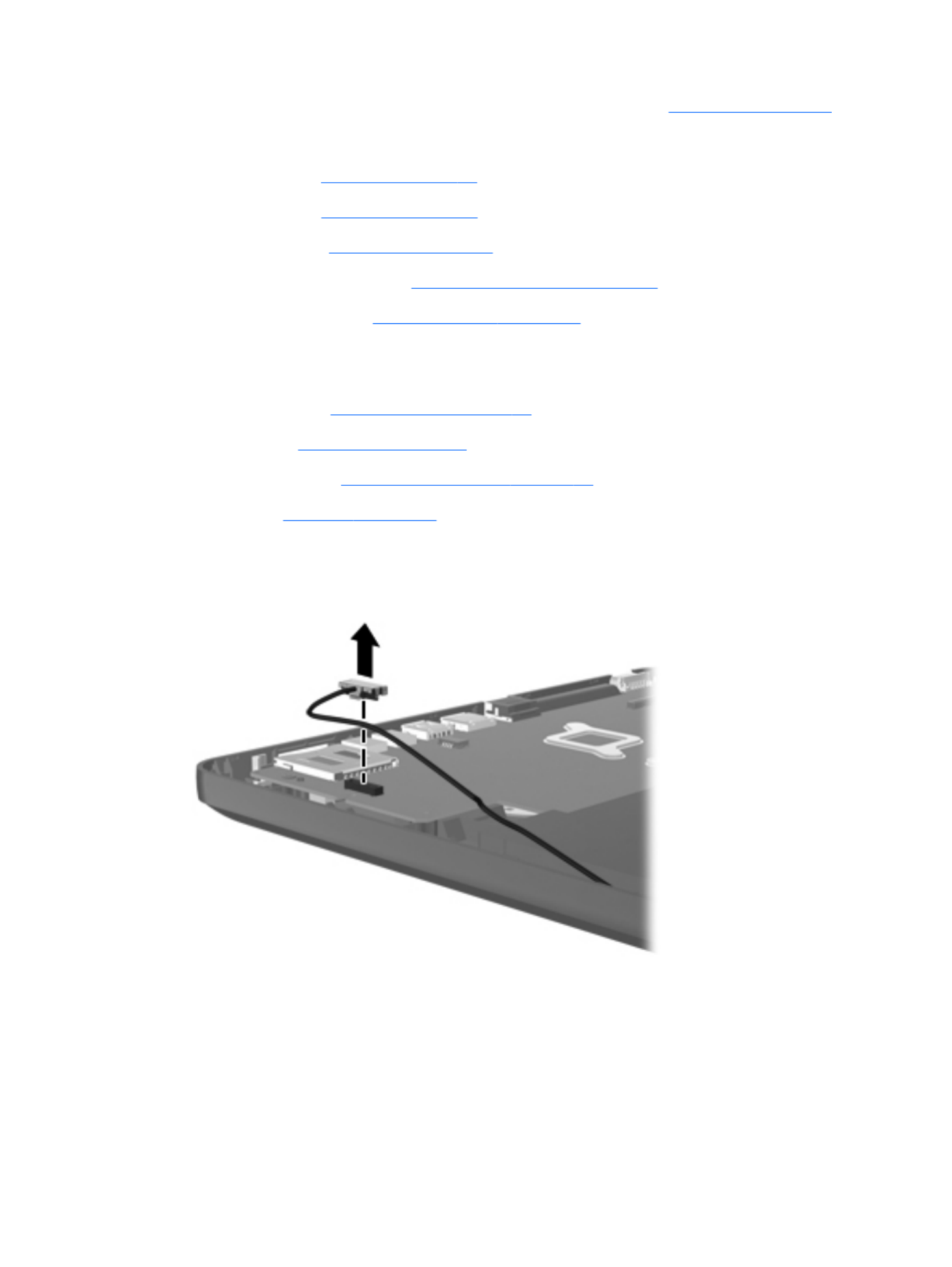
7. Disconnect the hard drive connector cable from the system board (see Hard drive on page 46).
8. Remove the following components:
●Keyboard (see Keyboard on page 49)
●Top cover (see Top cover on page 52)
●USB board (see USB board on page 59)
●Power connector cable (see Power connector cable on page 60)
●Display assembly (see Display assembly on page 64)
When replacing the system board, be sure that the following components are removed from the
defective system board and installed on the replacement system board:
●Memory module (see Memory module on page 45)
●RTC battery (see RTC battery on page 74)
●Fan and heat sink (see Fan/heat sink assembly on page 76)
●Processor (see Processor on page 82)
Remove the system board:
1. Disconnect the optical drive connector cable from the system board.
2. Remove the Phillips PM2.5×6.0 screw (1) that secures the system board to the base enclosure.
3. Lift the right side of the system board (2) until it rests at an angle.
72 Chapter 4 Removal and replacement procedures

RTC battery
Description Spare part number
RTC battery (includes cable and double-sided tape) 646132-001
Before removing the RTC battery, follow these steps:
1. Shut down the computer. If you are unsure whether the computer is off or in Hibernation, turn the
computer on, and then shut it down through the operating system.
2. Disconnect all external devices connected to the computer.
3. Disconnect the power from the computer by first unplugging the power cord from the AC outlet
and then unplugging the AC adapter from the computer.
4. Remove the battery (see Battery on page 39), and then remove the following components:
●Optical drive (see Optical drive (select models only) on page 40)
●WLAN module (see WLAN module on page 43)
●Keyboard (see Keyboard on page 49)
●Top cover (see Top cover on page 52)
●USB board (see USB board on page 59)
●Power connector cable (see Power connector cable on page 60)
●Display assembly (see Display assembly on page 64)
●System board (see System board on page 71)
Remove the RTC battery:
1. Turn the system board upside down, with the front toward you.
2. Disconnect the RTC battery cable (1) from the system board.
74 Chapter 4 Removal and replacement procedures

3. Detach the RTC battery (2) from the system board. (The RTC battery is attached to the system
board with double-sided tape.)
4. Remove the RTC battery.
Reverse this procedure to install the RTC battery.
Component replacement procedures 75

Fan/heat sink assembly
NOTE: The fan/heat sink assembly spare part kit includes replacement thermal material.
Replacement thermal material is also available in the Thermal Material Kit, spare part numbers
650277-001 (for use only with computer models equipped with an AMD processor) and 646135-001
(for use only with computer models equipped with an Intel processor).
Description Spare part number
For use only with computer models equipped with an AMD processor 647316-001
For use only with computer models equipped with an Intel Core i5 or i3 processor and a graphics
subsystem with discrete video memory
646182-001
For use only with computer models equipped with an Intel Core i5 or i3 processor and a graphics
subsystem with UMA video memory
646183-001
For use only with computer models equipped with an Intel Pentium processor and a graphics
subsystem with discrete video memory
646180-001
For use only with computer models equipped with an Intel Pentium processor and a graphics
subsystem with UMA video memory
646181-001
For use only with computer models equipped with an Intel Celeron processor and a graphics
subsystem with UMA video memory
646184-001
NOTE: To properly ventilate the computer, allow at least 7.6 cm (3 in) of clearance on the left side of
the computer. The computer uses an electric fan for ventilation. The fan is controlled by a temperature
sensor and is designed to turn on automatically when high temperature conditions exist. These
conditions are affected by high external temperatures, system power consumption, power
management/battery conservation configurations, battery fast charging, and software requirements.
Exhaust air is displaced through the ventilation grill located on the left side of the computer.
Before removing the fan/heat sink assembly, follow these steps:
1. Shut down the computer. If you are unsure whether the computer is off or in Hibernation, turn the
computer on, and then shut it down through the operating system.
2. Disconnect all external devices connected to the computer.
3. Disconnect the power from the computer by first unplugging the power cord from the AC outlet
and then unplugging the AC adapter from the computer.
4. Remove the battery (see Battery on page 39), and then remove the following components:
●Optical drive (see Optical drive (select models only) on page 40)
●WLAN module (see WLAN module on page 43)
●Keyboard (see Keyboard on page 49)
●Top cover (see Top cover on page 52)
●USB board (see USB board on page 59)
●Power connector cable (see Power connector cable on page 60)
76 Chapter 4 Removal and replacement procedures
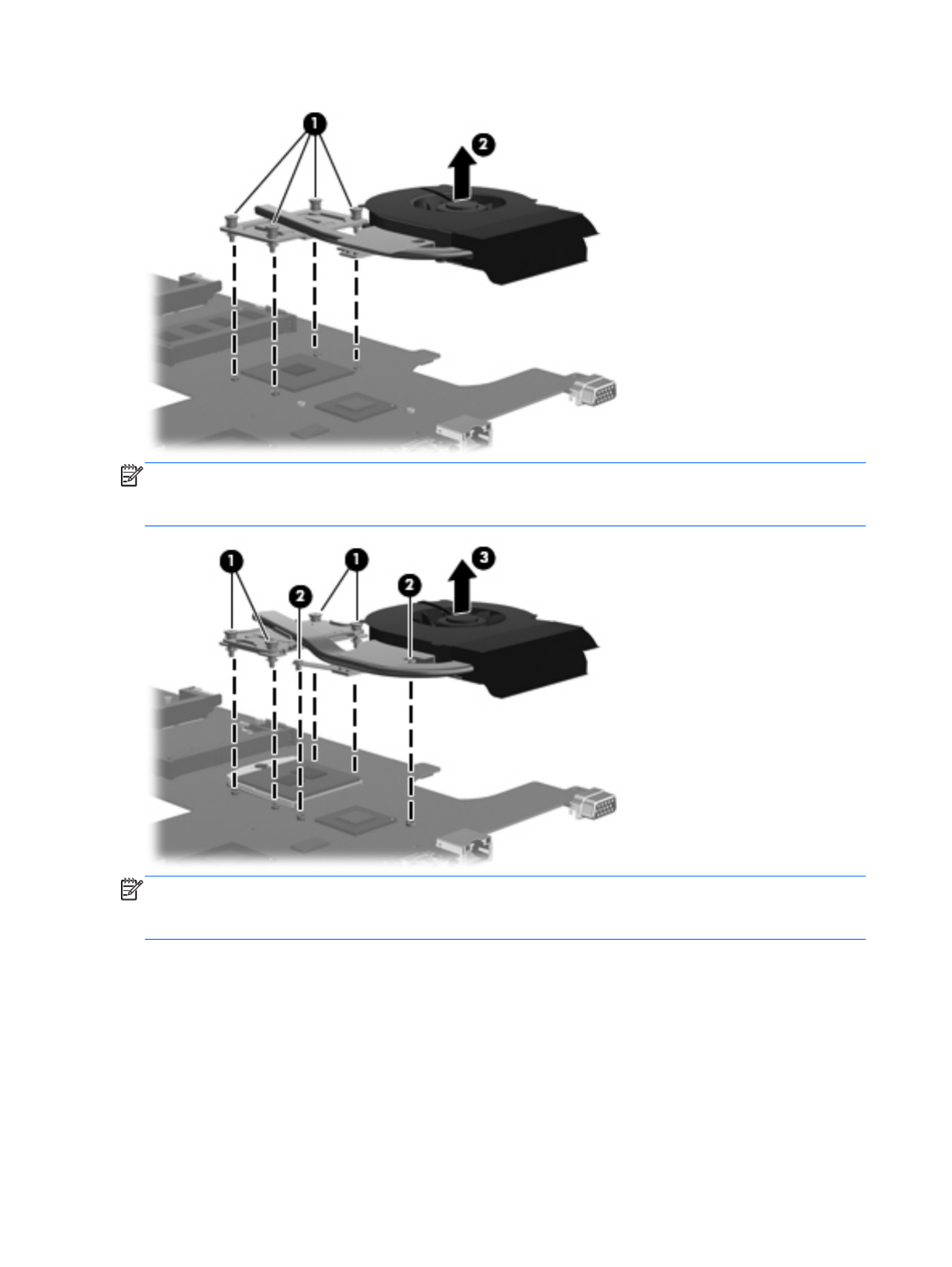
NOTE: The following illustration shows the fan/heat sink assembly removal process on a computer
model equipped with an Intel processor, the Intel HM65 or HM55 chipset, and a graphics subsystem
with discrete memory.
NOTE: The following illustration shows the fan/heat sink assembly removal process on a computer
model equipped with an Intel processor, the Intel HM65 or HM55 chipset, and a graphics subsystem
with UMA memory.
78 Chapter 4 Removal and replacement procedures
Specyfikacje produktu
| Marka: | HP |
| Kategoria: | laptop |
| Model: | Compaq Presario CQ57 |
| Kolor produktu: | Czarny |
| Typ produktu: | Laptop |
| Wysokość produktu: | 35.8 mm |
| Szerokość produktu: | 376 mm |
| Głębokość produktu: | 247 mm |
| Waga produktu: | 2550 g |
| Podręcznik użytkownika: | Tak |
| Bluetooth: | Nie |
| Zasilacz sieciowy: | Tak |
| Kraj pochodzenia: | Chiny |
| Technologia baterii: | Litowo-jonowa (Li-Ion) |
| Długość przekątnej ekranu: | 15.6 " |
| Obsługiwane typy kart pamięci: | MMC, SD |
| Standardy komunikacyjne: | IEEE 802.11b, IEEE 802.11g, IEEE 802.11n |
| Prędkość transferu danych przez Ethernet LAN: | 10, 100 Mbit/s |
| Ilość portów Ethernet LAN (RJ-45): | 1 |
| Zakres temperatur (eksploatacja): | 5 - 35 °C |
| Zakres wilgotności względnej: | 10 - 90 % |
| Układ: | Muszla |
| Rozdzielczość: | 1366 x 768 px |
| Natywne proporcje obrazu: | 16:9 |
| Ekran dotykowy: | Nie |
| Taktowanie procesora: | 1.65 GHz |
| Typ procesora: | AMD E |
| Model procesora: | E-450 |
| Wi-Fi: | Tak |
| Standardy Wi- Fi: | 802.11b, 802.11g, Wi-Fi 4 (802.11n) |
| Przewody: | Prąd przemienny |
| Liczba portów USB 2.0: | 3 |
| Przewodowa sieć LAN: | Tak |
| Zintegrowany czytnik kart: | Tak |
| Typ portu ładowania: | DC-in jack |
| Zakres temperatur (przechowywanie): | -20 - 60 °C |
| Dopuszczalna wilgotność względna: | 5 - 95 % |
| Producent procesora: | AMD |
| Liczba rdzeni procesora: | 2 |
| Typ pamięci wewnętrznej: | DDR3-SDRAM |
| Pamięć wewnętrzna: | 4 GB |
| Zainstalowany system operacyjny: | Windows 7 Home Premium |
| Maksymalna pojemność pamięci: | 4 GB |
| Port wyjścia S/PDIF: | Nie |
| Mikrofon: | Tak |
| Zawiera sterowniki: | Tak |
| Technologia okablowania: | 10/100Base-T(X) |
| Klawiatura numeryczna: | Nie |
| Urządzenie wskazujące: | Panel dotykowy |
| Kensington Lock: | Nie |
| Liczba portów VGA (D-Sub): | 1 |
| Nośniki: | HDD |
| Ilość wbudowanych glosników: | 2 |
| Producent głośników: | Altec Lansing |
| Moc adaptera AC: | 65 W |
| Dopuszczalna wysokość podczas eksploatacji (n.p.m.): | -15 - 3048 m |
| Port DVI: | Nie |
| Powierzchnia wyświetlacza: | Połysk |
| Czas pracy na zasilaniu akumulatorowym: | - h |
| Wbudowany mikrofon: | Tak |
| Podświetlenie LED: | Tak |
| Klawisze Windows: | Tak |
| Pełnowymiarowa klawiatura: | Tak |
| Gniazdo smartcard: | Nie |
| Pojemność HDD: | 500 GB |
| Szybkość HDD: | 5400 RPM |
| Rozmiar HDD: | 2.5 " |
| Całkowita pojemność przechowywania: | 500 GB |
| Interfejs HDD: | SATA |
| Typ pamięci procesora: | L2 |
| Cache procesora: | 1 MB |
| Liczba wątków: | 2 |
| Układ pamięci: | 1 x 4 GB |
| Karta graficzna on-board: | Tak |
| Model karty graficznej on-board: | AMD Radeon HD 6320 |
| Typ zintegrowanej karty graficznej: | AMD Radeon HD 6000 |
| Intel® Small Business Advantage (Intel® SBA): | Nie |
| Napędy optyczne: | DVD Super Multi DL |
| Architektura systemu operacyjnego: | 64-bit |
| Dopuszczalna wysokość (n.p.m.): | -15 - 12192 m |
| Rodzaj pamięci: | SO-DIMM |
| Złącze dokowania: | Nie |
| Obsluga ExpressCard: | Nie |
| Typ gniazda cardbus pcmcia: | Nie |
| Ilość komór baterii: | 6 |
| Maksymalna pamięć wewnętrzna (64-bit): | 4 GB |
| Liczba zainstalowanych HDD: | 1 |
Potrzebujesz pomocy?
Jeśli potrzebujesz pomocy z HP Compaq Presario CQ57, zadaj pytanie poniżej, a inni użytkownicy Ci odpowiedzą
Instrukcje laptop HP

4 Marca 2025
17 Lutego 2025
6 Lutego 2025
12 Stycznia 2025
11 Stycznia 2025
28 Grudnia 2024
27 Grudnia 2024
27 Grudnia 2024
21 Grudnia 2024
21 Grudnia 2024
Instrukcje laptop
- laptop Sony
- laptop Samsung
- laptop Fellowes
- laptop LG
- laptop Xiaomi
- laptop Huawei
- laptop Lenovo
- laptop Gigabyte
- laptop Acer
- laptop Fujitsu
- laptop Panasonic
- laptop Viewsonic
- laptop Asus
- laptop Medion
- laptop MSI
- laptop Toshiba
- laptop Haier
- laptop Prixton
- laptop Hyundai
- laptop Honor
- laptop Tripp Lite
- laptop Zebra
- laptop Dell
- laptop Schneider
- laptop Thomson
- laptop Pyle
- laptop Apple
- laptop Razer
- laptop ADATA
- laptop GoClever
- laptop SPC
- laptop NEC
- laptop Oregon Scientific
- laptop Jay-Tech
- laptop Microsoft
- laptop ECS
- laptop XPG
- laptop Denver
- laptop Lexibook
- laptop Micromax
- laptop Odys
- laptop TechBite
- laptop TrekStor
- laptop Alienware
- laptop Airis
- laptop Emachines
- laptop Hähnel
- laptop Sylvania
- laptop Coby
- laptop Evga
- laptop Naxa
- laptop Ricatech
- laptop Mpman
- laptop Vizio
- laptop Targa
- laptop Peaq
- laptop Ematic
- laptop Hannspree
- laptop Inovia
- laptop Ergotron
- laptop Ibm
- laptop Atdec
- laptop Packard Bell
- laptop Compaq
- laptop SIIG
- laptop Hercules
- laptop Kogan
- laptop Getac
- laptop Vulcan
- laptop System76
- laptop General Dynamics Itronix
- laptop CTL
- laptop Everex
- laptop Olidata
- laptop Dynabook
- laptop Hamilton Buhl
- laptop AORUS
- laptop Humanscale
- laptop Aplic
- laptop Schenker
Najnowsze instrukcje dla laptop

3 Kwietnia 2025

2 Kwietnia 2025

28 Marca 2025

28 Marca 2025
26 Marca 2025
13 Marca 2025
7 Marca 2025
1 Marca 2025
26 Lutego 2025
23 Lutego 2025