Instrukcja obsługi Hikvision DS-2TD6236-50H2L
Hikvision
Kamera monitorująca
DS-2TD6236-50H2L
Przeczytaj poniżej 📖 instrukcję obsługi w języku polskim dla Hikvision DS-2TD6236-50H2L (143 stron) w kategorii Kamera monitorująca. Ta instrukcja była pomocna dla 4 osób i została oceniona przez 2 użytkowników na średnio 4.5 gwiazdek
Strona 1/143

Therm -spectrum al Bi
Network Positioning System
User Manual
UD05158B

User Manual of Therm -spectrum Network Positioning System al Bi
© Hikvision
i
User
User
User
UserUser M
M
M
M Manua
anua
anua
anuaanual
l
l
ll
COPYRIGHT © 2017 Hangzhou Hikvision Digital Technology Co., Ltd.
AL
AL
AL
ALALL RIGHTS RESERVED.
L RIGHTS RESERVED.
L RIGHTS RESERVED.
L RIGHTS RESERVED.L RIGHTS RESERVED.
Any and all information, including, among others, wordings, pictures, graphs are the properties
of Hangzhou Hikvision Digital Technology Co., Ltd. or its subsidiaries (hereinafter referred to be
“Hikvision”). This user manual (hereinafter referred to be “the Manual”) cannot be reproduced,
changed, translated, or distributed, partially or wholly, by any means, without the prior written
permission of Hikvision. Unless otherwise stipulated, Hikvision does not make any warranties,
guarantees or representations, express or implied, regarding to the Manual.
Ab
Ab
Ab
AbAbout
out
out
outout t
t
t
t th
h
h
hhi
i
i
iis
s
s
s s Manu
Manu
Manu
ManuManual
al
al
alal
This Manual is applicable to Therm -spectrum Network Positioning Systemal Bi .
The Manual includes instructions for using and managing the product. Pictures, charts, images
and all other information hereinafter are for description and explanation only. The information
contained in the Manual is subject to change, without notice, due to firmware updates or other
reasons. Please find the latest version in the company website
( ). http://overseas.hikvision.com/en/
Please use this user manual under the guidance of professionals.
T
T
T
TTrademark
rademark
rademark
rademarkrademarks A
s A
s A
s As Ack
ck
ck
ckcknowl
nowl
nowl
nowlnowled
ed
ed
ededge
ge
ge
gegement
ment
ment
mentment
and other Hikvision’s trademarks and logos are the properties of Hikvision in
various jurisdictions. Other trademarks and logos mentioned below are the properties of their
respective owners.
Legal
Legal
Legal
LegalLegal Di
Di
Di
Di Discl
scl
scl
sclsclai
ai
ai
aiaimer
mer
mer
mermer
TO THE MAXIMUM EXTENT PERMITTED BY APPLICABLE LAW, THE PRODUCT DESCRIBED,
WITH ITS HARDWARE, SOFTWARE AND FIRMWARE, IS PROVIDED “AS IS”, WITH ALL FAULTS
AND ERRORS, AND HIKVISION MAKES NO WARRANTIES, EXPRESS OR IMPLIED, INCLUDING
WITHOUT LIMITATION, MERCHANTABILITY, SATISFACTORY QUALITY, FITNESS FOR A
PARTICULAR PURPOSE, AND NON-INFRINGEMENT OF THIRD PARTY. IN NO EVENT WILL
HIKVISION, ITS DIRECTORS, OFFICERS, EMPLOYEES, OR AGENTS BE LIABLE TO YOU FOR
ANY SPECIAL, CONSEQUENTIAL, INCIDENTAL, OR INDIRECT DAMAGES, INCLUDING, AMONG
OTHERS, DAMAGES FOR LOSS OF BUSINESS PROFITS, BUSINESS INTERRUPTION, OR LOSS
OF DATA OR DOCUMENTATION, IN CONNECTION WITH THE USE OF THIS PRODUCT, EVEN IF
HIKVISION HAS BEEN ADVISED OF THE POSSIBILITY OF SUCH DAMAGES.
REGARDING TO THE PRODUCT WITH INTERNET ACCESS, THE USE OF PRODUCT SHALL BE
WHOLLY AT YOUR OWN RISKS. HIKVISION SHALL NOT TAKE ANY RESPONSIBILITES FOR
ABNORMAL OPERATION, PRIVACY LEAKAGE OR OTHER DAMAGES RESULTING FROM CYBER
ATTACK, HACKER ATTACK, VIRUS INSPECTION, OR OTHER INTERNET SECURITY RISKS;
HOWEVER, HIKVISION WILL PROVIDE TIMELY TECHNICAL SUPPORT IF REQUIRED.
SURVEILLANCE LAWS VARY BY JURISDICTION. PLEASE CHECK ALL RELEVANT LAWS IN
YOUR JURISDICTION BEFORE USING THIS PRODUCT IN ORDER TO ENSURE THAT YOUR USE

User Manual of Therm Network Positioning system al
© Hikvision
ii
CONFORMS THE APPLICABLE LAW. HIKVISION SHALL NOT BE LIABLE IN THE EVENT THAT
THIS PRODUCT IS USED WITH ILLEGITIMATE PURPOSES.
IN THE EVENT OF ANY CONFLICTS BETWEEN THIS MANUAL AND THE APPLICABLE LAW,
THE LATER PREVAILS.

User Manual of Therm Network Positioning system al
© Hikvision
iii
Regul
Regul
Regul
RegulRegulat
at
at
atatory
ory
ory
oryory Inf
Inf
Inf
Inf Infor
or
or
ororm
m
m
mmat
at
at
atati
i
i
iio
o
o
oon
n
n
nn
FCC Informati
FCC Informati
FCC Informati
FCC InformatiFCC Information
on
on
on on
Please take attention that changes or modification not expressly approved by the party
responsible for compliance could void the user’s authority to operate the equipment.
FCC com
FCC com
FCC com
FCC comFCC compl
pl
pl
plpli
i
i
iianc
anc
anc
ancance:
e:
e:
e:e:
This equipment has been tested and found to comply with the limits for
a Class A digital device, pursuant to part 15 of the FCC Rules. These limits are designed to
provide reasonable protection against harmful interference when the equipment is
operated in a commercial environment. This equipment generates, uses, and can radiate
radio frequency energy and, if not installed and used in accordance with the instruction
manual, may cause harmful interference to radio communications. Operation of this
equipment in a residential area is likely to cause harmful interference in which case the
user will be required to correct the interference at his own expense.
FCC C
FCC C
FCC C
FCC CFCC Con
on
on
onondi
di
di
diditi
ti
ti
tition
on
on
onons
s
s
s s
This device complies with part 15 of the FCC Rules. Operation is subject to the following
two conditions:
1. This device may not cause harmful interference.
2. This device must accept any interference received, including interference that may
cause undesired operation.
EU Confor
EU Confor
EU Confor
EU ConforEU Conformit
mit
mit
mitmity S
y S
y S
y Sy Stat
tat
tat
tattatement
ement
ement
ementement
This product and - if applicable - the supplied accessories too are marked
with "CE" and comply therefore with the applicable harmonized European
standards listed under the Low Voltage Directive 2006/95/EC, the EMC
Directive 2014/30 U, the RoHS Directive 2011/65/EU. /E
2012/19/EU (WEEE directive): Products marked with this symbol cannot be
disposed of as unsorted municipal waste in the European Union. For
proper recycling, return this product to your local supplier upon the
purchase of equivalent new equipment, or dispose of it at designated
collection points. For more information see: www.recyclethis.info.
2006/66/EC (battery directive): This product contains a battery that cannot
be disposed of as unsorted municipal waste in the European Union. See
the product documentation for specific battery information. The battery is
marked with this symbol, which may include lettering to indicate cadmium
(Cd), lead (Pb), or mercury (Hg). For proper recycling, return the battery to your supplier or
to a designated collection point. For more information see: www.recyclethis.info.
Ind
Ind
Ind
IndIndust
ust
ust
ustustr
r
r
rry
y
y
y y Canad
Canad
Canad
CanadCanada I
a I
a I
a Ia ICES-
CES-
CES-
CES-CES-0
0
0
0003
03
03
0303 Co
Co
Co
Co Compli
mpli
mpli
mplimpliance
ance
ance
anceance
This device meets the CAN ICES-3 (A)/NMB-3(A) standards requirements.

User Manual of Therm Network Positioning system al
© Hikvision
iv
Saf
Saf
Saf
SafSafet
et
et
etety
y
y
yy In
In
In
In Inst
st
st
ststr
r
r
rruct
uct
uct
uctucti
i
i
iion
on
on
onon
These instructions are intended to ensure that the user can use the product correctly to
avoid danger or property loss.
The precaution measure is divided into ‘Warnings’ and ‘Cautions’:
W
W
W
WWarni
arni
arni
arniarning
ng
ng
ngngs
s
s
ss: Serious injury or death may be caused if any of these warnings are neglected.
Cauti
Cauti
Cauti
CautiCaution
on
on
onons
s
s
ss: Injury or equipment damage may be caused if any of these cautions are
neglected.
W
W
W
WWarni
arni
arni
arniarning
ng
ng
ngngs
s
s
ss Follow these safeguards to
prevent serious injury or death.
Cauti
Cauti
Cauti
CautiCaution
on
on
onons
s
s
ss Follow these precautions to
prevent potential injury or material damage.
Warni
Warni
Warni
WarniWarnings
ngs
ngs
ngsngs
The device should be used in compliance with local laws and electrical safety regulations. Refer to the
appropriate documentation for detailed information.
The input voltage should conform to IEC60950-1 standard: SELV (Safety Extra Low Voltage) and the
Limited Power Source (24 VAC/12 VDC). Refer to the appropriate documentation for detailed
information.
DO NOT connect multiple devices to one power adapter, to avoid over-heating or fire hazards caused
by overload.
Make sure the plug is properly connected to the power socket.
If smoke, odor, or noise arises from the device, immediately turn off the power, unplug the power cable,
and contact the service center.
The installer and user are responsible for password and security configuration and its settings.
Both internal and external grounds should be connected properly. (The cross section area of the
grounding wire must be no less than 4 mm2, and no less than that of the phase connector).
Caut
Caut
Caut
CautCauti
i
i
iions
ons
ons
onsons
Do not drop the device or subject it to physical shock.
Wipe the device gently with a clean cloth and a small quantity of ethanol, if necessary.
Do not aim the lens at the sun or any other bright light.
When any laser equipment is in use, make sure that the device lens is not exposed to the laser beam, or
it may burn out.
Do not expose the device to high electromagnetic radiation or extremely hot, cold, dusty, or damp
environments.
Place the device in a dry and well-ventilated environment.
Keep non-waterproof devices away from liquids.
Keep the device in original or similar packaging while transporting it.
A few device components (e.g., electrolytic capacitor) require regular replacement. The average lifespan
varies, so periodic checking is recommended. Contact your dealer for details.
Improper use or replacement of the battery may result in explosion hazard. Replace with the same or
equivalent type only. Dispose of used batteries in conformance with the instructions provided by the
battery manufacturer.
Never attempt to disassemble the device.
0504001070316

User Manual of Therm Network Positioning system al
© Hikvision
v
Table of Contents
Chapt
Chapt
Chapt
ChaptChapter 1
er 1
er 1
er 1er 1 Over
Over
Over
OverOverv
v
v
vvi
i
i
iiew
ew
ew
ewew ................................................................................................................... 1
1.1 Overview .................................................................................................................................. 1
1.2 System Requirement ............................................................................................................. 1
1.3 Functions ................................................................................................................................ 2
Chapter 2 Netwo
Netwo
Netwo
NetwoNetwork
rk
rk
rkrk Conn
Conn
Conn
Conn Connect
ect
ect
ectecti
i
i
iion
on
on
onon ................................................................................................ 4
2.1 Setting the Network Positioning system over the LAN ..................................................... 4
2.1.1 4 Wiring over the LAN ..........................................................................................................
2.1.2 Activating the Positioning system ................................................................................... 5
2.2 Setting the Network Positioning system over the WAN .................................................. 10
2.2.1 Static IP Connection........................................................................................................ 10
2.2.2 Dynamic IP Connection .................................................................................................. 11
Chapt
Chapt
Chapt
ChaptChapter 3
er 3
er 3
er 3er 3 Ac
Ac
Ac
AcAccess
cess
cess
cess cess to
to
to
to to the
the
the
the the Net
Net
Net
NetNetwork
work
work
workwork P
P
P
P Posi
osi
osi
osiosit
t
t
tti
i
i
iioni
oni
oni
onioning
ng
ng
ngng sy
sy
sy
sy syste
ste
ste
stestem
m
m
mm ......................................................... 14
3.1 Accessing by Web Browse rs .............................................................................................. 14
3.2 Accessing by Client Software ............................................................................................. 15
Chapt
Chapt
Chapt
ChaptChapter 4
er 4
er 4
er 4er 4 Bas
Bas
Bas
BasBasi
i
i
iic Op
c Op
c Op
c Opc Operat
erat
erat
eraterati
i
i
iions
ons
ons
onsons .................................................................................................... 17
4.1 Configuring Local Parameters ........................................................................................... 17
4.2 Live View Page ..................................................................................................................... 18
4.3 Starting Live View ................................................................................................................ 19
4.4 Operating PTZ Control ........................................................................................................21
4.4.1 PTZ Control Panel ....................................................................................................... 22
4.4.2 Auxiliary Functions ...................................................................................................... 23
4.4.3 Setting / Calling a Preset ............................................................................................ 25
4.4.4 Setting / Calling a Patrol ............................................................................................. 27
4.4.5 O -touch Patrolne ............................................................................................................. 29
4.4.6 Setting / Calling a Pattern .......................................................................................... 29
4.5 Playback ............................................................................................................................... 30
4.5.1 Play Back Video Files ...................................................................................................... 31
4.5.2 Downloading Video Files ................................................................................................32
4.6 Pictures ................................................................................................................................. 33
Chapt
Chapt
Chapt
ChaptChapter 5
er 5
er 5
er 5er 5 Sys
Sys
Sys
SysSystem Con
tem Con
tem Con
tem Contem Confi
fi
fi
fifig
g
g
ggurat
urat
urat
uraturati
i
i
iion
on
on
onon ............................................................................................ 35
5.1 Storage Settings .................................................................................................................. 35
5.1.1 Configuring Recording Schedule ............................................................................... 35
5.1.2 Configuring Capture Schedule ................................................................................... 37
5.1.3 Configuring Net HDD .................................................................................................. 39
5.2 Basic Event Configuration .................................................................................................. 41
5.2.1 Configuring Motion Detection........................................................................................ 41
5.2.2 Configuring Video Tampering Alarm ......................................................................... 46
5.2.3 Configuring Alarm Input ............................................................................................. 47
5.2.4 Configuring Alarm Output .......................................................................................... 49

User Manual of Therm Network Positioning system al
© Hikvision
vii
7.4.5 Configuring DPC Settings ......................................................................................... 116
7.4.6 Picture in Picture 117.......................................................................................................
7.5 Configuring System Settings ...........................................................................................118
7.5.1 System Settings ............................................................................................................ 118
7.5.2 Maintenance .............................................................................................................. 122
7.5.3 Security ....................................................................................................................... 126
7.5.4 User Management ..................................................................................................... 128
Appen
Appen
Appen
AppenAppendi
di
di
didix
x
x
xx ....................................................................................................................................... 133
SADP Software Introduction ......................................................................................................... 133
User Manual of Therm -spectrum Network Positioning System al Bi
© Hikvision
1
Chap
Chap
Chap
ChapChapt
t
t
tter
er
er
erer
1
1
1
11
O
O
O
OOv
v
v
vver
er
er
ererv
v
v
vvi
i
i
iiew
ew
ew
ew ew
1.
1.
1.
1.1.1
1
1
11 Overview
Therm -spectrum network positioning system (named as positioning system in the al bi
chapters below) integrates the function of the decoder, thermal camera, and the
high-definition zoom camera. I performs temperature measurement, dynamic fire source t
detection and other smart detections in the remote surveillance of the power system,
metallurgy system, and petrochemical engineering, and so on.
You can get a high-quality live view via web browser or client software.
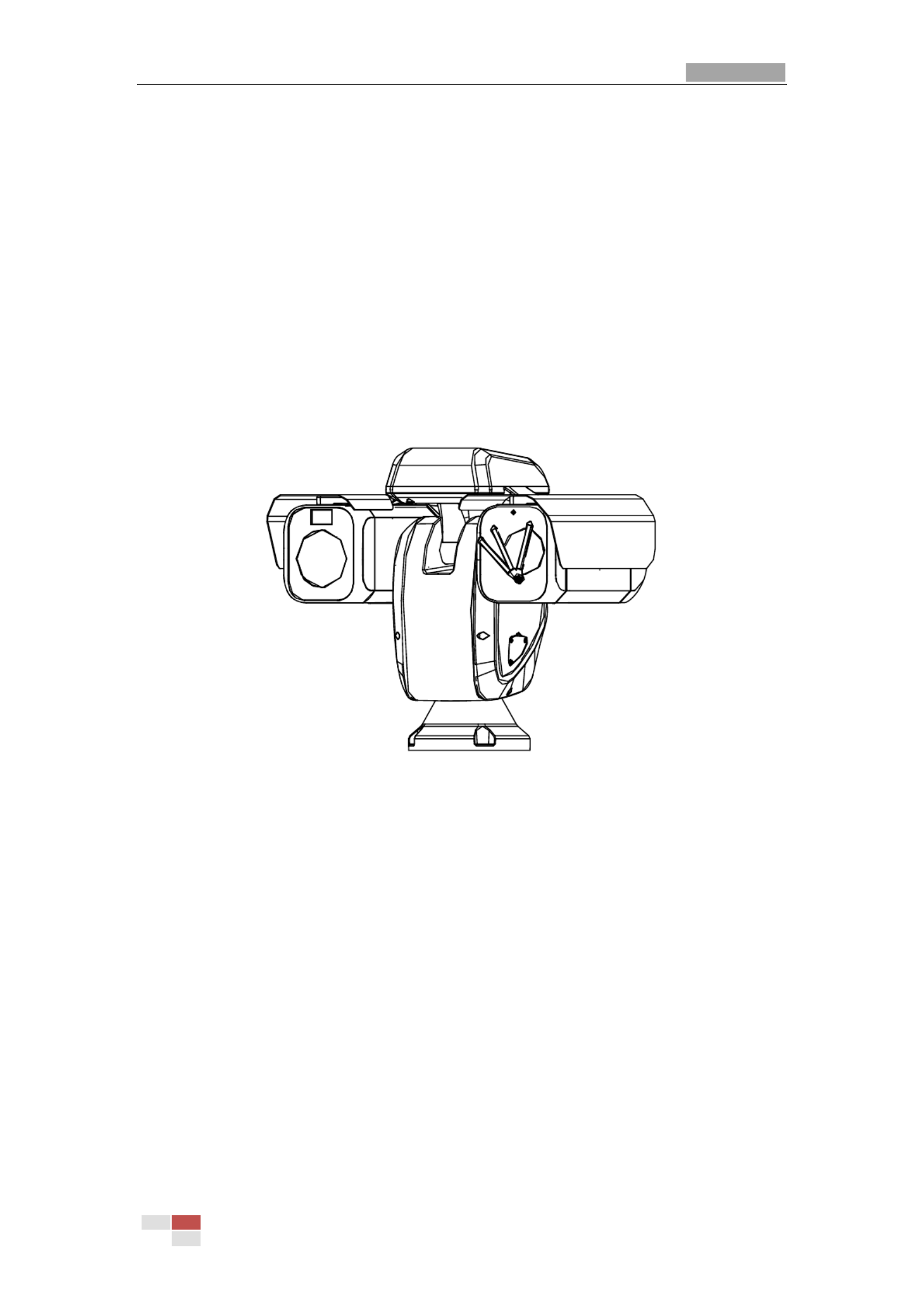
The figure below shows one type of the positioning system series.
Figure 1-1 Overview of Therm Positioning System al
1.
1.
1.
1.1.2
2
2
22 Sy
Sy
Sy
SySys
s
s
sst
t
t
tte
e
e
eem
m
m
mm R
R
R
R Re
e
e
eeq
q
q
qqui
ui
ui
uiuiremen
remen
remen
remenrement
t
t
tt
System requirement of web browser accessing is as follows:
Ope
Ope
Ope
OpeOperati
rati
rati
ratirating Sy
ng Sy
ng Sy
ng Syng Sys
s
s
sstem:
tem:
tem:
tem:tem:
Microsoft Windows XP SP1 and above version / Vista / Win7 / Server
2003 / Server 2008 32bits
CPU:
CPU:
CPU:
CPU:CPU: Intel Pentium IV 3.0 GHz or higher
RAM:
RAM:
RAM:
RAM:RAM: 1G or higher
Di
Di
Di
DiDispl
spl
spl
splsplay
ay
ay
ayay:
:
:
::
1024× 768 resolution or high er
We
We
We
WeWeb B
b B
b B
b Bb Browser
rowser
rowser
rowserrowser:
:
:
::
Internet Explorer 8.0 and above version, Apple Safari 5.02 and above version,
Mozilla Firefox 5 and above version and Google Chrome 18 and above versions.

User Manual of Therm Network Positioning system al
© Hikvision
2
1.
1.
1.
1.1.3
3
3
33 Funct
Funct
Funct
FunctFuncti
i
i
iion
on
on
onons
s
s
ss
The functions vary depending on the models of positioning system.
Bi
Bi
Bi
BiBi-
-
-
--sp
sp
sp
spspect
ect
ect
ectectrum
rum
rum
rum rum
The positioning system has two lens, an optical one and a thermal one, and two images
are respectively provided by each lens.
PTZ Limi
PTZ Limi
PTZ Limi
PTZ LimiPTZ Limits
ts
ts
tsts
The positioning system can be programmed to move within the PTZ limits (left/right,
up/down).
Scan M
Scan M
Scan M
Scan MScan Modes
odes
odes
odesodes
The positioning system provides 5 scan modes: auto scan, tilt scan, frame scan, random
scan and panorama scan.
Pre
Pre
Pre
PrePreset
set
set
setsets
s
s
s s
A preset is a predefined image position. When the preset is called, the positioning system
will automatically move to the defined position. The presets can be added, modified,
deleted and called.
Label
Label
Label
LabelLabel Di
Di
Di
Di Displ
spl
spl
splsplay
ay
ay
ay ay
The on-screen label of the preset title, azimuth/elevation, zoom, time and positioning
system name can be displayed on the monitor. The displays of time and positioning
system name can be programmed.
Au
Au
Au
AuAut
t
t
tto Fl
o Fl
o Fl
o Flo Fli
i
i
iips
ps
ps
psps
In manual tracking mode, when a target object goes directly beneath the positioning
system, the video will automatically flips 180 degrees in horizontal direction to maintain
continuity of tracking. This function can also be realized by auto mirror image depending
on different camera models.
Pr
Pr
Pr
PrPri
i
i
iivacy
vacy
vacy
vacyvacy Mas
Mas
Mas
Mas Mask
k
k
kk
This function allows you to block or mask certain area of a scene, for preventing the
personal privacy from recording or live viewing. A masked area will move with pan and tilt
functions and automatically adjust in size as the lens zooms telephoto and wide.
3D Pos
3D Pos
3D Pos
3D Pos3D Posi
i
i
iit
t
t
tti
i
i
iion
on
on
ononi
i
i
iing
ng
ng
ngng
In the client software, use the left key of mouse to click on the desired position in the video
image and drag a rectangle area in the lower right direction, then the itioning system pos
will move the position to the center and allow the rectangle area to zoom in. Use the left
key of mouse to drag a rectangle area in the upper left direction to move the position to the
center and allow the rectangle area to zoom out.
Pro
Pro
Pro
ProPropor
por
por
porporti
ti
ti
titiona
ona
ona
onaonal
l
l
ll P
P
P
P Pan/Ti
an/Ti
an/Ti
an/Tian/Til
l
l
llt
t
t
tt
Proportional pan/tilt automatically reduces or increases the pan and tilt speeds according
to the amount of zoom. At telephoto zoom settings, the pan and tilt speeds will be slower
than at wide zoom settings. This keeps the image from moving too fast on the live view
image when there is a large amount of zoom.
Au
Au
Au
AuAut
t
t
tto Focus
o Focus
o Focus
o Focus o Focus
The auto focus enables the camera to focus automatically to maintain clear video images.
Day/Ni
Day/Ni
Day/Ni
Day/NiDay/Night
ght
ght
ghtght Au
Au
Au
Au Aut
t
t
tto Swi
o Swi
o Swi
o Swio Swit
t
t
ttch
ch
ch
ch ch

User Manual of Therm Network Positioning system al
© Hikvision
3
The positioning systems deliver color images during the day. And as light diminishes at
night, the positioning systems switch to night mode and deliver black and white images
with high quality.
Sl
Sl
Sl
SlSlow Shu
ow Shu
ow Shu
ow Shuow Shutt
tt
tt
tttter
er
er
er er
In slow shutter mode, the shutter speed will automatically slow down in low illumination
conditions to maintain clear video images by extending the exposure time. The feature can
be enabled or disabled.
Ba
Ba
Ba
BaBackl
ckl
ckl
cklckli
i
i
iigh
gh
gh
ghght Compensat
t Compensat
t Compensat
t Compensatt Compensatio
io
io
ioion (B
n (B
n (B
n (Bn (BLC
LC
LC
LCLC)
)
)
))
If you focus on an object against strong backlight, the object will be too dark to be seen
clearly. The BLC (Backlight Compensation) function can compensate light to the object in
the front to make it clear, but this causes the over-exposure of the background where the
light is strong.
Wide
Wide
Wide
WideWide Dynamic
Dynamic
Dynamic
Dynamic Dynamic R
R
R
RRa
a
a
aange (
nge (
nge (
nge (nge (W
W
W
WWDR)
DR)
DR)
DR)DR)
The wide dynamic range (WDR) function helps the camera provide clear images even
under back light circumstances. When there are both very bright and very dark areas
simultaneously in the field of view, WDR balances the brightness level of the whole image
and provide clear images with details.
Whit
Whit
Whit
WhitWhite B
e B
e B
e Be Bal
al
al
alalance (
ance (
ance (
ance (ance (WB)
WB)
WB)
WB)WB)
White balance can remove the unrealistic color casts. White balance is the white rendition
function of the camera to adjust the color temperature according to the environment
automatically.
Pa
Pa
Pa
PaPatrol
trol
trol
troltrol
A patrol is a memorized series of pre-defined preset function. The scanning speed
between two presets and the dwell time at the preset are programmable.
Pa
Pa
Pa
PaPatt
tt
tt
ttttern
ern
ern
ern ern
A pattern is a memorized series of pan, tilt, zoom, and preset functions. By default the
focus and iris are in auto status during the pattern is being memorized.
Power O
Power O
Power O
Power OPower Off
ff
ff
ffff Memo
Memo
Memo
Memo Memo
ry
ry
ry
ryry
The positioning system supports the power off memory capability with the predefined
resume time. It allows the positioning system to resume its previous position after power
is restored.
Sch
Sch
Sch
SchSchedul
edul
edul
eduleduled T
ed T
ed T
ed Ted Task
ask
ask
askask
A time task is a preconfigured action that can be performed automatically at a specific
date and time. The programmable actions include: auto scan, random scan, patrol
1-8 ,pattern 1- preset 1-8,frame scan, panorama scan, tilt scan, day, night, reboot, PT 4,
adjust, Aux Output, etc.
Pa
Pa
Pa
PaPark
rk
rk
rkrk Act
Act
Act
Act Acti
i
i
iion
on
on
onon
This feature allows the positioning system to start a predefined action automatically after
a period of inactivity.
3D Di
3D Di
3D Di
3D Di3D Digi
gi
gi
gigita
ta
ta
tatal
l
l
ll Nois
Nois
Nois
Nois Noise Reduct
e Reduct
e Reduct
e Reducte Reduction
ion
ion
ionion
Comparing with the general 2D digital noise reduction, the 3D digital noise reduction
function processes the noise between two frames besides processing the noise in one
frame. The noise will be much less and the video will be clearer.
User Manual of Therm -spectrum Network Positioning System al Bi
© Hikvision
4
Chapter 2 Net
Net
Net
NetNetw
w
w
wwor
or
or
orork
k
k
kk C
C
C
C Con
on
on
ononn
n
n
nnec
ec
ec
ecect
t
t
tti
i
i
iion
on
on
onon
Be
Be
Be
BeBefore yo
fore yo
fore yo
fore yofore you st
u st
u st
u stu star
ar
ar
arart
t
t
tt:
:
:
::
If you want to set the network positioning system via a LAN (Local Area Network),
please refer to
Secti
Secti
Secti
SectiSection 2
on 2
on 2
on 2on 2.
.
.
..1.
1.
1.
1.1.
If you want to set the network positioning system via a WAN (Wide Area Network),
please refer to Sect
Sect
Sect
Sect Secti
i
i
iion
on
on
onon 2.
2.
2.
2. 2.2.
2.
2.
2.2.
2.1 Se
Se
Se
SeSet
t
t
ttt
t
t
tti
i
i
iing
ng
ng
ngng t
t
t
t th
h
h
hhe
e
e
ee
Net
Net
Net
NetNetwor
wor
wor
worwork
k
k
kk P
P
P
P Po
o
o
oos
s
s
ssi
i
i
iiti
ti
ti
titio
o
o
ooni
ni
ni
nining
ng
ng
ngng s
s
s
s sy
y
y
yys
s
s
sst
t
t
ttem
em
em
emem ov
ov
ov
ov ove
e
e
eer
r
r
r r
t
t
t
tthe
he
he
hehe L
L
L
L LA
A
A
AAN
N
N
NN
Pu
Pu
Pu
PuPurpose
rpose
rpose
rposerpose:
:
:
::
To view and configure the positioning system via a LAN, you need to connect the network
positioning system in the same subnet with your computer, and install the SADP or client
software to search and change the IP of the network positioning system.
For the detailed introduction of SADP, please refer to Appendix.
2.1.1 Wi
Wi
Wi
WiWiri
ri
ri
riring o
ng o
ng o
ng ong over
ver
ver
verver t
t
t
t th
h
h
hhe L
e L
e L
e Le LA
A
A
AAN
N
N
N N
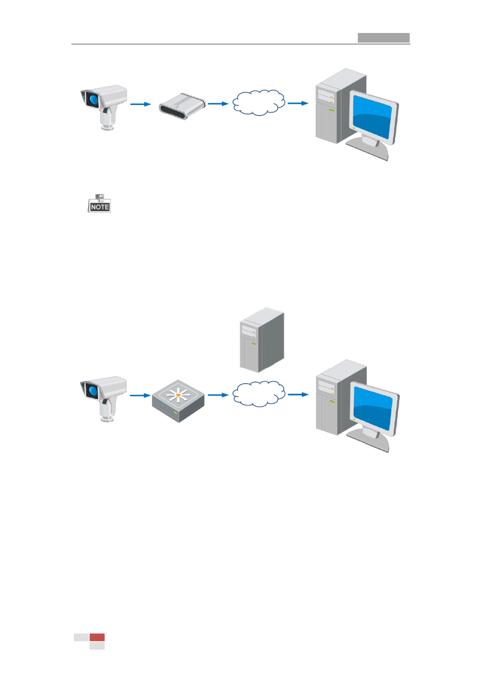
The following figures show the two ways of cable connection of a network positioning
system and a computer:
Pu
Pu
Pu
PuPurpose
rpose
rpose
rposerpose:
:
:
::
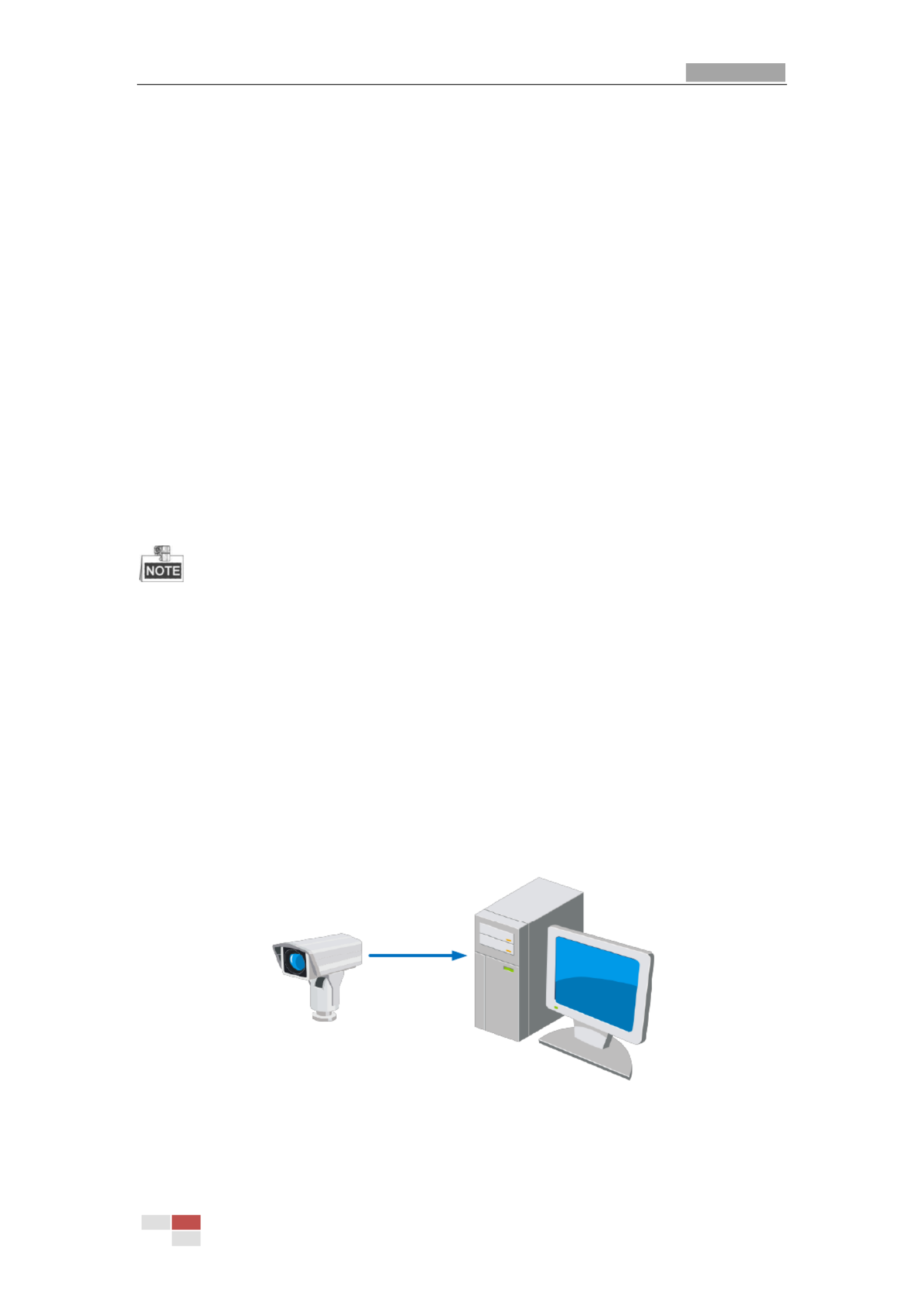
To test the network positioning system, you can directly connect the network
positioning system to the computer with a network cable as shown in Figure 2-1.
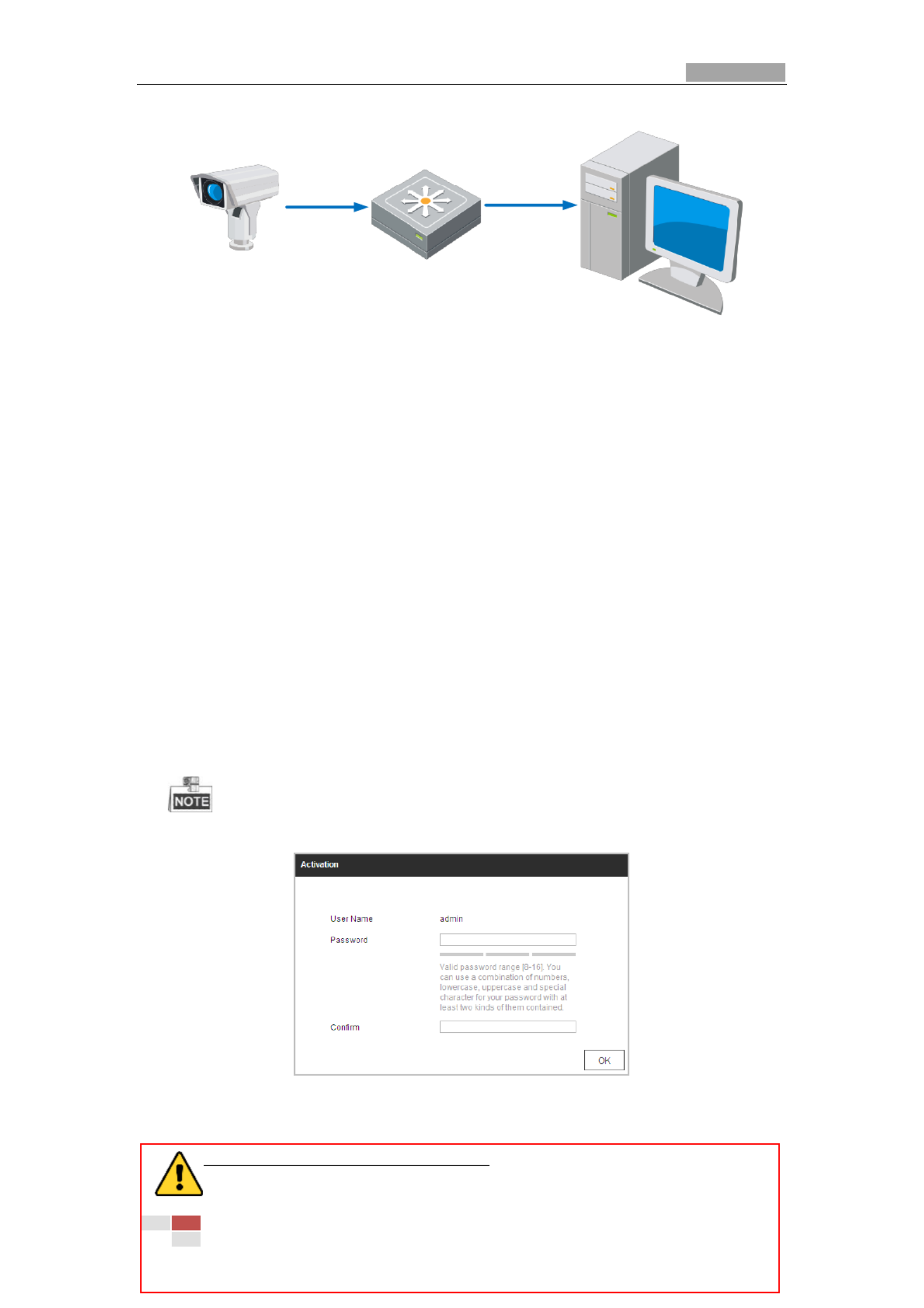
Refer to the Figure 2-2 to set the network positioning system over the LAN via a
switch or a router.
Network Cable
PT Camera
Figure 2-1 Connecting Directly
User Manual of Therm Network Positioning system al
© Hikvision
5
Network Cable
Switch or Router
PC
Network Cable
PT Camera
Figure 2-2 Connecting via a Switch or a Router
2.1.2 A
A
A
AAct
ct
ct
ctcti
i
i
iivat
vat
vat
vatvati
i
i
iin
n
n
nng t
g t
g t
g tg th
h
h
hhe
e
e
e e P
P
P
PPo
o
o
oos
s
s
ssi
i
i
iit
t
t
tti
i
i
iio
o
o
ooni
ni
ni
nining
ng
ng
ngng s
s
s
s sys
ys
ys
ysyst
t
t
ttem
em
em
emem
Pu
Pu
Pu
PuPurpose
rpose
rpose
rposerpose:
:
:
::
You are required to activate the positioning system rst before you can use the positioning fi
system.
Activation via Web Browser, Activation via SADP, and Activation via client software are
supported. In the following sections, activation via web browser and SADP will be taken as
examples. You may refer to the user manual of the positioning system for the details of
activation via client software.
A
A
A
AAct
ct
ct
ctcti
i
i
iiv
v
v
vvat
at
at
atati
i
i
iio
o
o
oon v
n v
n v
n vn vi
i
i
iia
a
a
aa W
W
W
W Web B
eb B
eb B
eb Beb Browse
rowse
rowse
rowserowser
r
r
rr
St
St
St
StSteps:
eps:
eps:
eps:eps:
1. Power on the positioning system, and connect the positioning system to the network.
2. Input the IP address into the address bar of the web browser, and click to enter
En
En
En
EnEnter
ter
ter
terter
the activation interface.
The default IP address of the positioning system is 192.168.1.64.
Figure 2-3 Activation Interface(Web)
3. Create a password and input the password into the password field.
STRONG
STRONG
STRONG
STRONGSTRONG
P
P
P
PPA
A
A
AASSWORD
SSWORD
SSWORD
SSWORDSSWORD
RECOMMENDED
RECOMMENDED
RECOMMENDED
RECOMMENDEDRECOMMENDED–We highly recommend you create a
strong password of your own choosing (Using a minimum of 8 characters,

User Manual of Therm Network Positioning system al
© Hikvision
7
regularly, especially in the high security system, resetting the password
monthly or weekly can better protect your product.
4. Click to save the password.
OK
OK
OK
OKOK
You can check whether the activation is completed on the popup window. If activation
failed, please make sure that the password meets the requirement and then try again.
5. Change the device IP address to the same subnet with your computer by either
modifying the IP address manually or checking the checkbox of .
Enabl
Enabl
Enabl
EnablEnable DHCP
e DHCP
e DHCP
e DHCPe DHCP
Figure 2-5 Modify the IP Address
6. Input the password and click to activate your IP address modification.
Save
Save
Save
SaveSave
A
A
A
AActi
cti
cti
ctictivat
vat
vat
vatvati
i
i
iion v
on v
on v
on von via
ia
ia
iaia Cl
Cl
Cl
Cl Cli
i
i
iient
ent
ent
entent Sof
Sof
Sof
Sof Soft
t
t
ttw
w
w
wware
are
are
are are
The client software is versatile video management software for multiple kinds of devices.
Get the client software from the supplied disk or the official website, and install the
software according to the prompts. Follow the steps to activate the camera.
St
St
St
StSteps:
eps:
eps:
eps:eps:
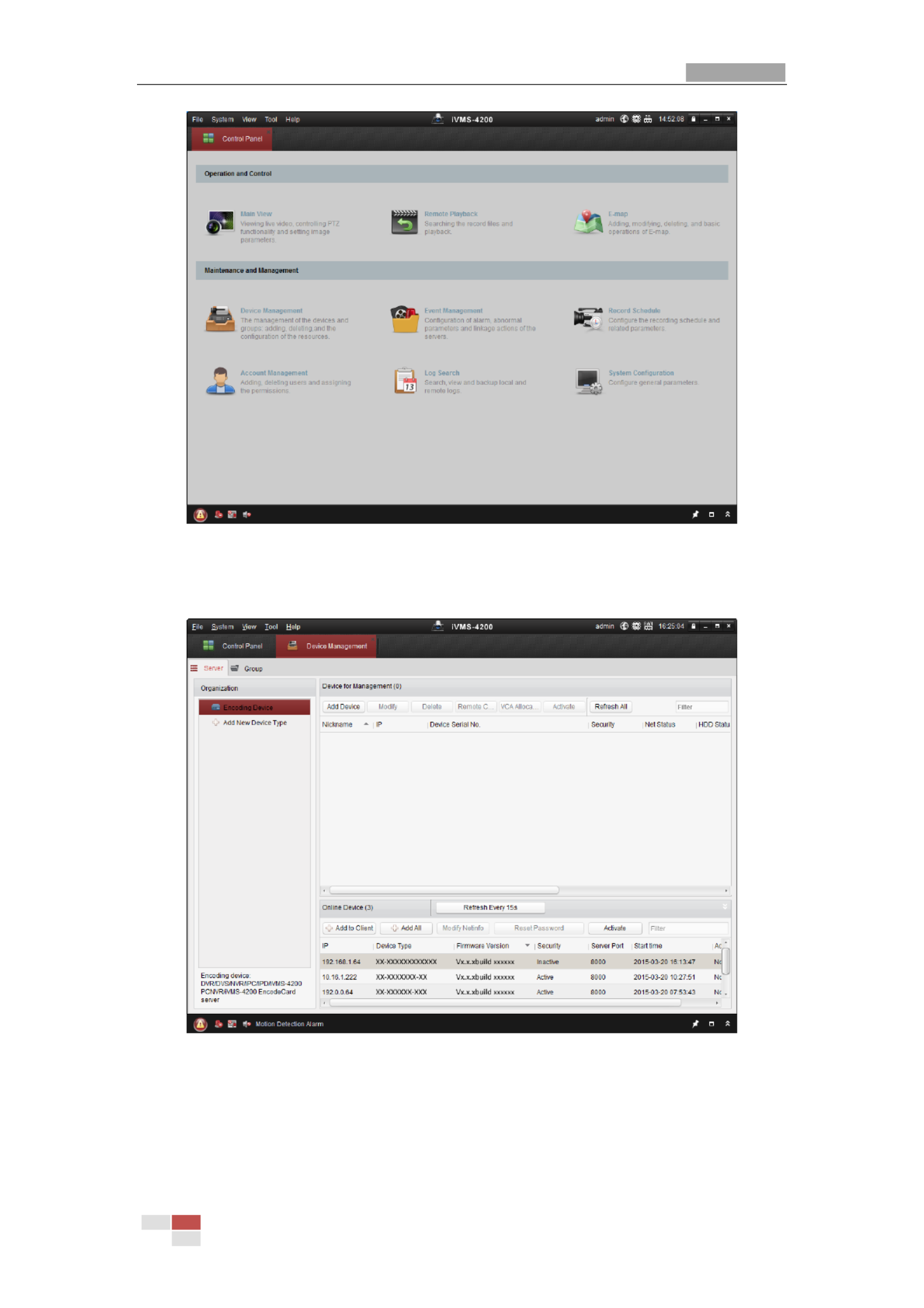
1. Run the client software and the control panel of the software pops up, as shown in the
figure below.
User Manual of Therm Network Positioning system al
© Hikvision
8
Figure 2-6 Control Panel
2. Click to enter the Device Management interface, as shown in the
Devi
Devi
Devi
DeviDevice Ma
ce Ma
ce Ma
ce Mace Management
nagement
nagement
nagementnagement
figure below.
Figure 2-7 Device Management Interface
3. Check the device status from the device list, and select an inactive device.
4. Click to pop up the Activation interface.
Act
Act
Act
ActActi
i
i
iivate
vate
vate
vatevate
5. Create a password and input the password in the password field, and confirm the
password.

User Manual of Therm Network Positioning system al
© Hikvision
10
2.2 Se
Se
Se
SeSet
t
t
ttt
t
t
tti
i
i
iin
n
n
nng t
g t
g t
g tg th
h
h
hhe
e
e
e e Net
Net
Net
NetNetwor
wor
wor
worwork
k
k
kk P
P
P
P Pos
os
os
ososi
i
i
iit
t
t
tti
i
i
iion
on
on
ononi
i
i
iin
n
n
nng s
g s
g s
g sg sy
y
y
yyst
st
st
stste
e
e
eem o
m o
m o
m om ove
ve
ve
vever
r
r
r r
t
t
t
tthe
he
he
hehe W
W
W
W WA
A
A
AAN
N
N
N N
Pu
Pu
Pu
PuPurpose
rpose
rpose
rposerpose:
:
:
::
This section explains how to connect the network positioning system to the WAN with a
static IP or a dynamic IP.
2.2.1 St
St
St
StStat
at
at
atati
i
i
iic
c
c
c c IP
IP
IP
IPIP Con
Con
Con
Con Conne
ne
ne
nenect
ct
ct
ctcti
i
i
iion
on
on
onon
Be
Be
Be
BeBefore you
fore you
fore you
fore youfore you st
st
st
st start
art
art
artart:
:
:
::
Please apply a static IP from an ISP (Internet Service Provider). With the static IP address,
you can connect the network positioning system via a router or connect it to the WAN
directly.
Connec
Connec
Connec
ConnecConnecti
ti
ti
titing t
ng t
ng t
ng tng the n
he n
he n
he nhe net
et
et
etetw
w
w
wwork
ork
ork
orkork po
po
po
po posi
si
si
sisiti
ti
ti
titio
o
o
ooni
ni
ni
nining sys
ng sys
ng sys
ng sysng system v
tem v
tem v
tem vtem vi
i
i
iia a rout
a a rout
a a rout
a a routa a router
er
er
er er
St
St
St
StSteps:
eps:
eps:
eps:eps:
1. Connect the network positioning system to the router.
2. Assign a LAN IP address, the subnet mask and the gateway. Refer to for
S
S
S
SSect
ect
ect
ectecti
i
i
iion
on
on
on on 2.
2.
2.
2.2.1
1
1
11.
.
.
..2
2
2
2 2
detailed IP address configuration of the positioning system.
3. Save the static IP in the router.
4. Set port mapping, E.g., 80, 8000 and 554 ports. The steps for port mapping vary
depending on different routers. Please call the router manufacturer for assistance with
port mapping.
5. Visit the network positioning system through a web browser or the client software over
the internet.
Posioning
System
Network
Cable
Router with Stac IP
PC
Network
Cable
Network
Cable
Internet
Figure 2-10 Accessing the Positioning system through Router with Static IP
Connec
Connec
Connec
ConnecConnecti
ti
ti
titing t
ng t
ng t
ng tng the n
he n
he n
he nhe network
etwork
etwork
etworketwork
posi
posi
posi
posipositi
ti
ti
titioni
oni
oni
onioning sy
ng sy
ng sy
ng syng syst
st
st
ststem wit
em wit
em wit
em witem with st
h st
h st
h sth stati
ati
ati
atiatic
c
c
cc IP
IP
IP
IP IP di
di
di
didirectl
rectl
rectl
rectlrectly
y
y
yy
You can also save the static IP in the positioning system and directly connect it to the
internet without using a router. Refer to for detailed IP address configuration
Se
Se
Se
SeSecti
cti
cti
ctiction
on
on
on on 2.
2.
2.
2.2.1
1
1
11.
.
.
..2
2
2
22
of the positioning system.

User Manual of Therm Network Positioning system al
© Hikvision
11
Posioning
System
PC
Network
Cable
Network
Cable
Internet
Figure 2-11 Accessing the Positioning system with Static IP Directly
2.2.2 Dyn
Dyn
Dyn
DynDynami
ami
ami
amiamic I
c I
c I
c Ic IP
P
P
PP Conn
Conn
Conn
Conn Connect
ect
ect
ectecti
i
i
iio
o
o
oon
n
n
nn
Be
Be
Be
BeBefore you
fore you
fore you
fore youfore you st
st
st
st start
art
art
artart:
:
:
::
Please apply a dynamic IP from an ISP. With the dynamic IP address, you can connect the
network positioning system to a modem or a router.
Connec
Connec
Connec
ConnecConnecti
ti
ti
titing t
ng t
ng t
ng tng the n
he n
he n
he nhe network
etwork
etwork
etworketwork
posi
posi
posi
posipositi
ti
ti
titio
o
o
ooni
ni
ni
nining sy
ng sy
ng sy
ng syng syst
st
st
ststem vi
em vi
em vi
em viem via a rout
a a rout
a a rout
a a routa a router
er
er
er er
St
St
St
StSteps:
eps:
eps:
eps:eps:
1. Connect the network positioning system to the router.
2. In the positioning system, assign a LAN IP address, the subnet mask and the gateway.
Refer to for detailed LAN configuration.
Sect
Sect
Sect
SectSecti
i
i
iion
on
on
on on 2.
2.
2.
2.2.1.
1.
1.
1.1.2
2
2
22
3. In the router, set the PPPoE user name, password and confirm the password.
For your privacy and to better protect your system against security risks, we
strongly recommend the use of strong passwords for all functions and network
devices. The password should be something of your own choosing (using a
minimum of 8 characters, including upper case letters, lower case letters, numbers
and special characters) in order to increase the security of your product.
Proper configuration of all passwords and other security settings is the
responsibility of the installer and/or end-user.
4. Set port mapping. E.g. 80, 8000 and 554 ports. The steps for port mapping vary
depending on different routers. Please call the router manufacturer for assistance with
port mapping.
5. Apply a domain name from a domain name provider.
6. Configure the DDNS settings in the setting interface of the router.
7. Visit the positioning system via the applied domain name.
Connec
Connec
Connec
ConnecConnecti
ti
ti
titing t
ng t
ng t
ng tng the n
he n
he n
he nhe network
etwork
etwork
etworketwork
posi
posi
posi
posipositi
ti
ti
titio
o
o
ooni
ni
ni
nining
ng
ng
ng ng syst
syst
syst
systsystem vi
em vi
em vi
em viem via a modem
a a modem
a a modem
a a modem a a modem
Pu
Pu
Pu
PuPurpose
rpose
rpose
rposerpose:
:
:
::
This positioning system supports the PPPoE auto dial-up function. The positioning
system gets a public IP address by ADSL dial-up after the positioning system is connected
to a modem. You need to configure the PPPoE parameters of the network positioning
system. Refer to for detailed configuration.
Secti
Secti
Secti
SectiSection
on
on
onon 7.
7.
7.
7. 7.1
1
1
11.
.
.
..1 Conf
1 Conf
1 Conf
1 Conf1 Confi
i
i
iiguri
guri
guri
guriguring
ng
ng
ngng PP
PP
PP
PP PPPoE Set
PoE Set
PoE Set
PoE SetPoE Setti
ti
ti
titings
ngs
ngs
ngs ngs
User Manual of Therm Network Positioning system al
© Hikvision
12
Posioning
System
Network
Cable
Modem
PC
Network
Cable
Network
Cable
Internet
Figure 2-12 Accessing the Positioning system with Dynamic IP
The obtained IP address is dynamically assigned via PPPoE, so the IP address always
changes after rebooting the positioning system. To solve the inconvenience of the
dynamic IP, you need to get a domain name from the DDNS provider (E.g.
DynDns.com). Please follow below steps for normal domain name resolution and
private domain name resolution to solve the problem.
Normal Domain Name Resolution
Posioning
System
Network
Cable
Router with Stac IP
PC
Network
Cable
Network
Cable
Internet
(Port Mapping)
Domain Name
Resoluon Server
Figure 2-13 Normal Domain Name Resolution
St
St
St
StSteps:
eps:
eps:
eps:eps:
1. Apply a domain name from a domain name provider.
2. Configure the DDNS settings in the interface of the network
DDNS
DDNS
DDNS
DDNS DDNS Set
Set
Set
SetSetti
ti
ti
titin
n
n
nngs
gs
gs
gsgs
positioning system. Refer to r detailed
Sect
Sect
Sect
SectSecti
i
i
iion
on
on
onon
7.
7.
7.
7.7.1.
1.
1.
1.1.1
1
1
11
Confi
Confi
Confi
ConfiConfigu
gu
gu
guguri
ri
ri
riring
ng
ng
ngng
DDNS
DDNS
DDNS
DDNS DDNS Set
Set
Set
SetSett
t
t
ttin
in
in
inings
gs
gs
gsgs fo
configuration.
3. Visit the positioning system via the applied domain name.
Private Domain Name Resolution

User Manual of Therm Network Positioning system al
© Hikvision
13
Posioning
System
Network
Cable
Router with Stac IP
PC
Network
Cable
Network
Cable
Internet
(Port Mapping)
PC + IP Server + Staic IP
Figure 2-14 Private Domain Name Resolution
St
St
St
StSteps:
eps:
eps:
eps:eps:
1. Install and run the IP Server software in a computer with a static IP.
2. Access the network positioning system through the LAN with a web browser or the
client software.
3. Enable DDNS and select IP Server as the protocol type. Refer to S
S
S
SSecti
ecti
ecti
ectiection
on
on
on on 7
7
7
77.
.
.
..1.
1.
1.
1.1.1
1
1
1 1
Conf
Conf
Conf
ConfConfi
i
i
iiguri
guri
guri
guriguring
ng
ng
ng ng DDNS Set
DDNS Set
DDNS Set
DDNS SetDDNS Setti
ti
ti
titings
ngs
ngs
ngsngs for detailed configuration.

User Manual of Therm -spectrum Network Positioning System al Bi
© Hikvision
14
Chap
Chap
Chap
ChapChapt
t
t
tter
er
er
erer
3
3
3
33
A
A
A
AAcce
cce
cce
ccecces
s
s
sss
s
s
ss
t
t
t
tto
o
o
oo t
t
t
t the
he
he
hehe
Net
Net
Net
NetNetwork
work
work
workwork
P
P
P
PPo
o
o
oos
s
s
ssi
i
i
iit
t
t
tti
i
i
iion
on
on
ononi
i
i
iing
ng
ng
ng ng s
s
s
ssy
y
y
yys
s
s
sst
t
t
tte
e
e
eem
m
m
m m
3.
3.
3.
3.3.1
1
1
11 A
A
A
AAcce
cce
cce
ccecces
s
s
sssi
si
si
sising b
ng b
ng b
ng bng by
y
y
yy
W
W
W
WWeb
eb
eb
ebeb B
B
B
B Bro
ro
ro
rorowser
wser
wser
wserwsers
s
s
s s
St
St
St
StSteps
eps
eps
epseps:
:
:
::
1. Open the web browser.
2. In the address field, input the IP address of the network positioning system, e.g.,
192.168.1.64 and press the key to enter the login interface.
En
En
En
EnEnte
te
te
teter
r
r
rr
3. Activate the positioning system for the first time using, refer to the s
s
s
ssecti
ecti
ecti
ectiectio
o
o
oon 2
n 2
n 2
n 2n 2.
.
.
..1.
1.
1.
1.1.2
2
2
2 2
Ac
Ac
Ac
AcActi
ti
ti
titiv
v
v
vvat
at
at
atati
i
i
iing
ng
ng
ng ng the
the
the
thethe Po
Po
Po
Po Posi
si
si
sisit
t
t
tti
i
i
iioni
oni
oni
onioning sy
ng sy
ng sy
ng syng syst
st
st
ststem
em
em
emem.
4. Select English as the interface language on the top-right of login interface.
5. Input the user name and password and click .
The admin user should configure the device accounts and user/operator permissions
properly. Delete the unnecessary accounts and user/operator permissions.
The device IP address gets locked if the admin user performs 7 failed password
attempts (5 attempts for the user/operator).
Figure 3-1 Login Interface
6. Install the plug-in before viewing the live video and operating the positioning system.
Please follow the installation prompts to install the plug- . in
You may have to close the web browser to install the plug-in. Please reopen the web
browser and log in again after installing the plug-in.

User Manual of Therm Network Positioning system al
© Hikvision
15
Figure 3-2 Download and Install Plug-in
3.
3.
3.
3.3.2
2
2
22 A
A
A
AAcce
cce
cce
ccecces
s
s
sss
s
s
ssi
i
i
iing
ng
ng
ngng b
b
b
b by
y
y
yy
Cl
Cl
Cl
ClCli
i
i
iien
en
en
enent
t
t
tt S
S
S
S So
o
o
oof
f
f
fft
t
t
ttware
ware
ware
wareware
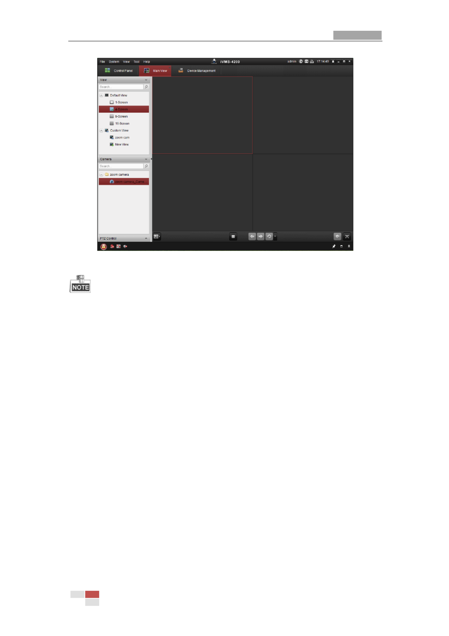
The product CD contains the client software. You can view the live video and manage the
positioning system with the client software.
Follow the installation prompts to install the client software and WinPcap. The
configuration interface and live view interface of client software are shown bel . ow
Figure 3-3 iVMS-4200 Control Panel
User Manual of Therm Network Positioning system al
© Hikvision
16
Figure 3-4 iVMS-4200 Live View Interface
If you use third party VMS software, please contact technical support of our branch
for camera firmware.
For detailed information about client software of our company, please refer to the
user manual of the software. This manual mainly introduces accessing to the network
positioning system by web browser.

User Manual of Therm -spectrum Network Positioning System al Bi
© Hikvision
17
Chap
Chap
Chap
ChapChapt
t
t
tter
er
er
erer
4
4
4
44
B
B
B
BBa
a
a
aas
s
s
ssi
i
i
iic
c
c
c c Op
Op
Op
OpOpe
e
e
eera
ra
ra
rarat
t
t
tti
i
i
iion
on
on
onons
s
s
ss
In this and the following chapters, operation of the positioning system by the web browser
will be taken as an example.
4.
4.
4.
4.4.1
1
1
11 Conf
Conf
Conf
ConfConfi
i
i
iigu
gu
gu
guguri
ri
ri
ririn
n
n
nng
g
g
gg Loca
Loca
Loca
Loca Local
l
l
ll P
P
P
P Par
ar
ar
araramet
amet
amet
ametamete
e
e
eers
rs
rs
rsrs
The local configuration refers to the parameters of the live view and other operations
using the web browser.
St
St
St
StSteps
eps
eps
epseps:
:
:
::
1. Enter the Local Configuration interface:
Conf
Conf
Conf
ConfConfi
i
i
iigurat
gurat
gurat
guratgurati
i
i
iion
on
on
onon > Local
> Local
> Local
> Local > Local
Figure 4-1 Local Configuration Interface
2. Configure the following settings:
Li
Li
Li
LiLive
ve
ve
ve ve Vi
Vi
Vi
ViView P
ew P
ew P
ew Pew Paramet
aramet
aramet
arametarameters:
ers:
ers:
ers:ers:
Set the protocol type, play performance, rules and image
format.
Pro
Pro
Pro
ProProtoc
toc
toc
toctocol
ol
ol
olol T
T
T
T Ty
y
y
yyp
p
p
ppe:
e:
e:
e:e: TCP, UDP, MULTICAST and HTTP are selectable.
TC
TC
TC
TCTCP
P
P
PP
:
:
:
:: Ensures complete delivery of streaming data and better video quality, yet the
real-time transmission will be affected.
UDP
UDP
UDP
UDPUDP
:
:
:
:: Provides real-time audio and video streams.
MUL
MUL
MUL
MULMULTICAST
TICAST
TICAST
TICASTTICAST
:
:
:
:: It’s recommended to select the protocol type to MUL
MUL
MUL
MULMULTICAST
TICAST
TICAST
TICASTTICAST when
using the Multicast function.
HTT
HTT
HTT
HTTHTTP
P
P
PP
:
:
:
:: Allows the same quality as of TCP without setting specific ports for
streaming under some network environments.
Pl
Pl
Pl
PlPlay Pe
ay Pe
ay Pe
ay Peay Perfo
rfo
rfo
rforformance:
rmance:
rmance:
rmance:rmance: Set the play performance to Shortest Delay, or Auto.

User Manual of Therm Network Positioning system al
© Hikvision
18
Rul
Rul
Rul
RulRules:
es:
es:
es:es: You can enable or disable the rules of dynamic analysis for motion here.
Image Format:
Image Format:
Image Format:
Image Format:Image Format: The captured pictures can be saved as different format. JPEG and
BMP are available.
Record Fi
Record Fi
Record Fi
Record FiRecord Fil
l
l
lle S
e S
e S
e Se Set
et
et
etetti
ti
ti
titin
n
n
nngs:
gs:
gs:
gs:gs: Set the saving path of the video files.
Record
Record
Record
Record Record Fi
Fi
Fi
FiFil
l
l
lle
e
e
ee
Si
Si
Si
SiSize:
ze:
ze:
ze:ze:
Select the packed size of manually recorded and downloaded
video files. The size can be set to 256M, 512M or 1G.
Save
Save
Save
Save Save record f
record f
record f
record frecord fi
i
i
iil
l
l
lles
es
es
es es to:
to:
to:
to:to:
Set the saving path for the manually recorded video files.
Save
Save
Save
Save Save d
d
d
ddownl
ownl
ownl
ownlownloaded
oaded
oaded
oadedoaded
fi
fi
fi
fifil
l
l
lle
e
e
ees
s
s
s s to:
to:
to:
to:to:
Set the saving path for the downloaded video files in
interface.
Pi
Pi
Pi
PiPicture
cture
cture
cture cture and
and
and
and and Cl
Cl
Cl
ClClip
ip
ip
ipip
S
S
S
SSett
ett
ett
ettetti
i
i
iings:
ngs:
ngs:
ngs:ngs:
Set the saving paths of the captured pictures and clipped
video files.
Save
Save
Save
Save Save snaps
snaps
snaps
snapssnapshot
hot
hot
hothots
s
s
s s in
in
in
inin
l
l
l
lli
i
i
iive
ve
ve
ve ve vi
vi
vi
vivie
e
e
eew
w
w
w w to:
to:
to:
to:to: Set the saving path of the manually captured
pictures in interface.
Save
Save
Save
Save Save snapsh
snapsh
snapsh
snapshsnapshots
ots
ots
otsots when p
when p
when p
when p when pl
l
l
llayb
ayb
ayb
aybayback
ack
ack
ackack to
to
to
to to:
:
:
::
Set the saving path of the captured pictures in
interface.
Save
Save
Save
Save Save cl
cl
cl
clcli
i
i
iips
ps
ps
ps ps to:
to:
to:
to:to:
Set the saving path of the clipped video files in
interface.
You can click to change the directory for saving video files, clips and
Browse
Browse
Browse
BrowseBrowse
pictures.
You can click to directly open the video files, clips and pictures.
Open
Open
Open
OpenOpen
3. Click to save the settings.
4.
4.
4.
4.4.2
2
2
22 Li
Li
Li
LiLive
ve
ve
ve ve V
V
V
VVi
i
i
iiew P
ew P
ew P
ew Pew Page
age
age
ageage
Pu
Pu
Pu
PuPurpose
rpose
rpose
rposerpose:
:
:
::
The live video page allows you to view live video, capture images, realize PTZ control,
set/call presets and configure video parameters.
Log in the network positioning system to enter the live view page, or you can click
on the menu bar of the main page to enter the live view page.

User Manual of Therm Network Positioning system al
© Hikvision
19
Descri
Descri
Descri
DescriDescript
pt
pt
ptption
ion
ion
ionions of t
s of t
s of t
s of ts of the l
he l
he l
he lhe liv
iv
iv
ivive vi
e vi
e vi
e vie view page:
ew page:
ew page:
ew page:ew page:
Live View
Parameters
Live View Window
Toolbar
Show or hide
PTZ control
panel
PTZ Control
Preset/Patrol/Pattern
Menu Bar
Figure 4-2 Live View Page
Menu
Menu
Menu
MenuMenu Bar:
Bar:
Bar:
Bar: Bar:
Click each tab to enter Live View, Playback, Picture, and Configuration page respectively.
Click to display the help file of the positioning system.
Click to logout the system.
Li
Li
Li
LiLive V
ve V
ve V
ve Vve View Wind
iew Wind
iew Wind
iew Windiew Window
ow
ow
owow:
:
:
::
Display the live video.
Tool
Tool
Tool
ToolToolbar:
bar:
bar:
bar:bar:
Operations on the live view page, e.g., live view, capture, record, audio on/off, regional
exposure, regional focus, etc.
PTZ Contr
PTZ Contr
PTZ Contr
PTZ ContrPTZ Control:
ol:
ol:
ol:ol:
Panning, tilting, focusing and zooming actions of the positioning system. The lighter, wiper,
one-touch focus and lens initialization control.
Pr
Pr
Pr
PrPreset/
eset/
eset/
eset/eset/patrol
patrol
patrol
patrolpatrol/pat
/pat
/pat
/pat/pattern
tern
tern
terntern:
:
:
::
Set and call the preset/patrol/pattern for the positioning system.
Pattern function varies depending on the models of positioning system.
Li
Li
Li
LiLive V
ve V
ve V
ve Vve View Par
iew Par
iew Par
iew Pariew Param
am
am
amamete
ete
ete
eteeters:
rs:
rs:
rs:rs:
Configure the image size, stream type, plug-in type, and two-way audio of the live video.
4.
4.
4.
4.4.3
3
3
33 St
St
St
StStar
ar
ar
arart
t
t
tti
i
i
iing
ng
ng
ng ng Li
Li
Li
LiLive
ve
ve
veve Vi
Vi
Vi
Vi View
ew
ew
ew ew
In the live view window as shown in Figure 4-3, click on the toolbar to start the live
view of the positioning system.

User Manual of Therm Network Positioning system al
© Hikvision
20
Figure 4-3 Start Live View
Table 4-1 Descriptions of the Toolbar
Ico
Ico
Ico
IcoIcon
n
n
n n
Descri
Descri
Descri
DescriDescript
pt
pt
ptpti
i
i
iion
on
on
onon
Ico
Ico
Ico
IcoIcon
n
n
n n
Descri
Descri
Descri
DescriDescript
pt
pt
ptpti
i
i
iion
on
on
onon
/
Start/Stop Live view.
Manually capture the
pictures.
/ /
/
Display in 4:3/16:9/original/
Self-adaptive window size.
/ /
Live view with the
main/sub/third stream.
/
Play via webcomponents/
quick time.
/
Start/Stop Two-way Audio.
/
Manual start/stop
recording.
/
Mute/Audio on and adjust
volume
/
Start/stop digital zoom.
/
Enable/Disable Regional
Exposure
/
Enable / Disable Regional
Focus
Double-click on the live video to switch the current live view into full-screen or return to
normal mode from the full-screen.
Click to select from and display live video in 4:3/16:9/
original/self-adaptive window size.
Click to select from and display live video with the main/
sub/third stream. The main stream is with a relatively high resolution and needs much
bandwidth. The default setting of stream type is .

User Manual of Therm Network Positioning system al
© Hikvision
22
4.
4.
4.
4.4.4.
4.
4.
4.4.1
1
1
11 P
P
P
PPTZ
TZ
TZ
TZTZ Cont
Cont
Cont
Cont Control
rol
rol
rolrol P
P
P
P Pa
a
a
aanel
nel
nel
nelnel
On the live view page, click to show the PTZ control panel or click to hide it.
Click the direction buttons to control the pan/tilt movements.
Click the zoom/iris/focus buttons to realize lens control.
Figure 4-4 PTZ Control Panel
Table 4-2 Descriptions of PTZ Control Panel
Bu
Bu
Bu
BuButt
tt
tt
tttton
on
on
on on
Name
Name
Name
Name Name
Descri
Descri
Descri
DescriDescrip
p
p
ppti
ti
ti
tition
on
on
on on
PTZ Control Panel
Hold and press the direction
button to pan/tilt the positioning
system.
Click and the positioning
system keeps panning, the icon
turns into . Click the icon again
to stop the positioning system.
Zoom out/in
Click , the lens zooms in, click
, and the lens zooms out.

User Manual of Therm Network Positioning system al
© Hikvision
23
Bu
Bu
Bu
BuButt
tt
tt
tttton
on
on
on on
Name
Name
Name
Name Name
Descri
Descri
Descri
DescriDescrip
p
p
ppti
ti
ti
tition
on
on
onon
Focus near/far
Click , the lens focus far and
the items far away gets clear. Click
, the lens focus near and the
items nearby gets clear.
Iris close/open
When the image is too dark, click
to open the iris. When the
image is too bright, click to
close the iris.
Auxiliary Functions
The auxiliary functions include
light, wiper, auxiliary focus, lens
initialization, manual tracking, 3D
positioning, one-touch patrol, and
one-touch park.
Speed Adjustment
Adjust speed of pan/tilt
movements.
Preset
Refer to for detailed
4.
4.
4.
4.4.4
4
4
44.
.
.
..3
3
3
33
information of setting preset.
Patrol
Refer to for detailed
4.
4.
4.
4.4.4
4
4
44.
.
.
..4
4
4
44
information of setting patrol.
Pattern
Refer to for detailed
4.
4.
4.
4.4.4
4
4
44.
.
.
..6
6
6
66
information of setting pattern.
Bu
Bu
Bu
BuButt
tt
tt
ttttons
ons
ons
onsons on
on
on
on on the
the
the
the the Prese
Prese
Prese
Prese Preset/
t/
t/
t/t/Pat
Pat
Pat
PatPatrol
rol
rol
rolrol/P
/P
/P
/P/Pat
at
at
atattern
tern
tern
ternterns i
s i
s i
s is in
n
n
nnter
ter
ter
terterface
face
face
faceface:
:
:
::
Table 4-3 Descriptions of Buttons
Bu
Bu
Bu
BuButt
tt
tt
ttttons
ons
ons
onsons
Descri
Descri
Descri
DescriDescrip
p
p
ppti
ti
ti
tition
on
on
onon
Start the selected patrol/pattern.
Stop current patrol/pattern.
Set the selected preset/patrol.
Delete the selected preset/patrol/pattern.
Start recording a pattern.
Stop recording the pattern.
4.
4.
4.
4.4.4.
4.
4.
4.4.2
2
2
22 A
A
A
AAux
ux
ux
uxuxi
i
i
iil
l
l
lli
i
i
iiar
ar
ar
arary
y
y
y y Func
Func
Func
FuncFunct
t
t
tti
i
i
iio
o
o
oons
ns
ns
nsns
The Auxiliary functions panel is shown in the figure below:

User Manual of Therm Network Positioning system al
© Hikvision
24
Figure 4-5 Auxiliary Functions
Light
Click to enable/disable the light supplement of the positioning system. This
function is reserved.
Wiper
Click to move the wiper once.
Auxiliary Focus
The auxiliary focus function is reserve d.
Click to enable manual -Icing function of the device. De
The de-icing function takes effect when the device inner temperature is 30°C (86≤°F).
Manual Tracking
Be
Be
Be
BeBefore yo
fore yo
fore yo
fore yofore you s
u s
u s
u su star
tar
tar
tartart
t
t
tt:
:
:
::
Please enter the Smart Tracking settings interface and enable smart tracking first.
Conf
Conf
Conf
ConfConfi
i
i
iigurat
gurat
gurat
guratgurati
i
i
iion >
on >
on >
on >on > PTZ > Smart Tracki
PTZ > Smart Tracki
PTZ > Smart Tracki
PTZ > Smart TrackiPTZ > Smart Trackin
n
n
nng
g
g
gg
St
St
St
StSteps
eps
eps
epseps:
:
:
::
1. Click on the toolbar of live view interface.
2. Click a moving object in the live video.
The positioning system will track the object automatically.
3D Positioning
St
St
St
StSteps
eps
eps
epseps:
:
:
::
1. Click on the toolbar of live view interface.
2. Operate the 3D positioning function:
3. Click a position of the live video. The corresponding position will be moved to the
center of the live video.
4. Hold down the left mouse button and drag the mouse to the lower right on the live
video. The corresponding position will be moved to the center of the live video and
zoomed in.
5. Hold down the left mouse button and drag the mouse to the upper left on the live video.
The corresponding position will be moved to the center of the live video and zoomed
out.

User Manual of Therm Network Positioning system al
© Hikvision
25
One-touch Patrol
Click to call one-touch patrol. For detailed information of setting one-touch
patrol, refer to .
4.
4.
4.
4.4.4.
4.
4.
4.4.5
5
5
55 One-
One-
One-
One- One-touch
touch
touch
touch touch Patrol
Patrol
Patrol
PatrolPatrol
One-touch Park
Click to save the current view as the preset No. 32 and start park at the the
current position.
4.
4.
4.
4.4.4.
4.
4.
4.4.3
3
3
33 Set
Set
Set
SetSett
t
t
tti
i
i
iing
ng
ng
ngng / Cal
/ Cal
/ Cal
/ Cal / Call
l
l
lli
i
i
iing
ng
ng
ngng a
a
a
a a Pre
Pre
Pre
PrePreset
set
set
setset
Pu
Pu
Pu
PuPurpose:
rpose:
rpose:
rpose:rpose:
A preset is a predefined image position. For the defined preset, you can click the calling
button to quickly view the desired image position.
Set
Set
Set
SetSetti
ti
ti
titing a
ng a
ng a
ng ang a Preset
Preset
Preset
Preset Preset:
:
:
::
St
St
St
StSteps:
eps:
eps:
eps:eps:
1. In the PTZ control panel, select a preset number from the preset list.
Figure 4-6 Setting a Preset
2. Use the PTZ control buttons to move the lens to the desired position.
• Pan the positioning system to the right or left.
• Tilt the positioning system up or down.
• Zoom in or out.
• Refocus the lens.
3. Click to finish the setting of the current preset.
4. Edit a preset name by double clicking on the default name such as preset 1. (The pre-defined presets
are named already and not configurable. Please refer to the user manual for detailed function
description.)
5. You can click to delete the preset.
You can configure up to 256 presets.
Cal
Cal
Cal
CalCalli
li
li
liling a
ng a
ng a
ng ang a Prese
Prese
Prese
Prese Preset:
t:
t:
t:t:
In the PTZ control panel, select a defined preset from the list and click to call the
preset.

User Manual of Therm Network Positioning system al
© Hikvision
26
Figure 4-7 Calling a Preset
For convenient preset selection, refer to the following steps to navigate to the preset you
want.
St
St
St
StSteps:
eps:
eps:
eps:eps:
1. Select any preset from the list.
2. Click the preset number you need on the keyboard.
The following presets are predefined with special commands. You can only call them
but not congure them. For instance, preset 99 is the “Start auto scan”. If you call the
preset 99, the positioning system starts auto scan function.
Pattern function varies depending on the models of positioning system .
Table 4-4 Special Presets
Pre
Pre
Pre
PrePreset
set
set
setset
Funct
Funct
Funct
FunctFunctio
io
io
ioion
n
n
n n
Pre
Pre
Pre
PrePreset
set
set
setset
Funct
Funct
Funct
FunctFunctio
io
io
ioion
n
n
n n
33
Auto flip
92
Start to set limit stops
34
Back to initial position
93
Set limit stops manually
35
Call patrol 1
94
Remote reboot
36
Call patrol 2
95
Call OSD menu
37
Call patrol 3
96
Stop a scan
38
Call patrol 4
97
Start random scan
39
Day mode (IR cut filter in)
98
Start frame scan
40
Night mode (IR cut filter out)
99
Start auto scan
41
Call pattern 1
100
Start tilt scan
42
Call pattern 2
101
Start panorama scan
43
Call pattern 3
102
Call patrol 5
44
Call pattern 4
103
Call patrol 6
45
One-touch Patrol
104
Call patrol 7
90
Wiper
105
Call patrol 8

User Manual of Therm Network Positioning system al
© Hikvision
27
Figure 4-8 Special Preset
You may need to use the OSD (On Screen Display) menu when controlling the
positioning system remotely. To display the OSD menu on the live view screen, you
can call the preset number 95.
4.
4.
4.
4.4.4.
4.
4.
4.4.4
4
4
44 S
S
S
SSet
et
et
etett
t
t
tti
i
i
iing /
ng /
ng /
ng /ng / Cal
Cal
Cal
Cal Call
l
l
lli
i
i
iin
n
n
nng
g
g
g g a P
a P
a P
a Pa Patro
atro
atro
atroatrol
l
l
ll
Pu
Pu
Pu
PuPurpose
rpose
rpose
rposerpose:
:
:
::
A patrol is a memorized series of preset function. It can be configured and called on the
patrol settings interface. There are up to 8 patrols for customizing. A patrol can be
configured with 32 presets.
Be
Be
Be
BeBefore yo
fore yo
fore yo
fore yofore you st
u st
u st
u stu star
ar
ar
arart
t
t
tt:
:
:
::
Please make sure that the presets you want to add into a patrol have been defined.
Set
Set
Set
SetSett
t
t
tti
i
i
iing
ng
ng
ng ng a Pa
a Pa
a Pa
a Paa Patro
tro
tro
trotrol
l
l
ll:
:
:
::
St
St
St
StSteps
eps
eps
epseps:
:
:
::
1. In the PTZ control panel, click to enter the patrol settings interface.
2. Select a patrol number from the list and click .
3. Click to enter the adding interface of preset, as shown in Figure 4-9.

User Manual of Therm Network Positioning system al
© Hikvision
28
Figure 4-9 Adding Presets
4. Configure the preset number, patrol time and patrol speed.
Name
Name
Name
Name Name
Descr
Descr
Descr
DescrDescrip
ip
ip
ipipt
t
t
tti
i
i
iion
on
on
on on
Patrol Time
It is the duration staying on one patrol point. The positioning
system moves to another patrol point after the patrol time.
Patrol Speed
It is the speed of moving from one preset to another.
5. Click to save a preset into the patro
OK
OK
OK
OKOK l.
6. Repeat the steps from 3 to 5 to add more presets.
7. Click to save all the patrol settings.
OK
OK
OK
OKOK
Cal
Cal
Cal
CalCall
l
l
lli
i
i
iing
ng
ng
ngng a P
a P
a P
a P a Pat
at
at
atatrol
rol
rol
rolrol:
:
:
::
In the PTZ control panel, select a defined patrol from the list and click to call the patrol,
as shown in Figure 4- . 10
Figure 4-10 Calling a Preset

User Manual of Therm Network Positioning system al
© Hikvision
29
4.4.5 On
On
On
OnOne-
e-
e-
e-e-t
t
t
tto
o
o
oouch
uch
uch
uchuch Pa
Pa
Pa
Pa Patro
tro
tro
trotrol
l
l
ll
Pu
Pu
Pu
PuPurpose:
rpose:
rpose:
rpose:rpose:
One-touch patrol is an automatically created patrol. The system automatically add preset
No.1 to No.32 to the patrol path 8. You can call the one-touch patrol and the positioning
system moves as the patrol path 8 automatically.
St
St
St
StSteps:
eps:
eps:
eps:eps:
1. Set preset No.1 to No.32. Refer to for detailed
4.
4.
4.
4.4.4
4
4
44.
.
.
..3 S
3 S
3 S
3 S3 Sett
ett
ett
ettetti
i
i
iing / Cal
ng / Cal
ng / Cal
ng / Calng / Call
l
l
lli
i
i
iing a
ng a
ng a
ng a ng a Preset
Preset
Preset
PresetPreset
information of setting preset.
2. Call preset No. 45, and the positioning system moves as patrol path 8.
3. Click to enter the patrol settings interface and start/stop one-touch patrol, edit
the patrol time and the speed.
4. You can click of the PTZ control panel to start one-touch patrol.
Figure 4-11 Patrol Path 8
4.
4.
4.
4.4.4.
4.
4.
4.4.6
6
6
66 Set
Set
Set
SetSett
t
t
tti
i
i
iin
n
n
nng /
g /
g /
g /g / Cal
Cal
Cal
Cal Call
l
l
lli
i
i
iing a
ng a
ng a
ng ang a P
P
P
P Pat
at
at
atatt
t
t
ttern
ern
ern
ernern
Pu
Pu
Pu
PuPurpose:
rpose:
rpose:
rpose:rpose:
A pattern is a memorized series of pan, tilt, zoom, and preset functions. It can be called on
the pattern settings interface. There are up to 4 patterns for customizing.
Pattern function varies depending on positioning system models.
Set
Set
Set
SetSetti
ti
ti
titing
ng
ng
ngng a Pa
a Pa
a Pa
a Pa a Patt
tt
tt
ttttern:
ern:
ern:
ern:ern:
St
St
St
StSteps:
eps:
eps:
eps:eps:
1. In the PTZ control panel, click to enter the pattern settings interface.
2. Select a pattern number from the list as shown in Figure 4- . 12

User Manual of Therm Network Positioning system al
© Hikvision
30
Figure 4-12 Patterns Settings Interface
3. Click to enable recording the panning, tilting and zooming actions.
4. Use the PTZ control buttons to move the lens to the desired position after the
information of PROGR
PROGR
PROGR
PROGRPROGRAM P
AM P
AM P
AM PAM PATTER
ATTER
ATTER
ATTERATTERN REMAINNI
N REMAINNI
N REMAINNI
N REMAINNIN REMAINNING
NG
NG
NGNG MEMORY(
MEMORY(
MEMORY(
MEMORY( MEMORY(%)
%)
%)
%)%) is displayed on the
screen.
Pan the positioning system to the right or left.
Tilt the positioning system up or down.
Zoom in or out.
Refocus the lens.
5. Click to save all the pattern settings.
Bu
Bu
Bu
BuButt
tt
tt
ttttons o
ons o
ons o
ons oons on th
n th
n th
n thn the Pat
e Pat
e Pat
e Pate Patter
ter
ter
terterns i
ns i
ns i
ns ins int
nt
nt
ntnterf
erf
erf
erferface:
ace:
ace:
ace:ace:
Bu
Bu
Bu
BuButt
tt
tt
ttttons
ons
ons
onsons
Descri
Descri
Descri
DescriDescript
pt
pt
ptpti
i
i
iion
on
on
onon
Start the selected patrol/pattern.
Stop current patrol/pattern.
Set the selected preset/patrol.
Delete the selected preset/patrol/pattern.
Start recording a pattern.
Stop recording the pattern.
These 4 patterns can be operated separately and with no priority level.
When configuring and calling the pattern, proportional pan is valid; the limit stops and
auto flip will be invalid; and the 3D positioning operation is not supported.
4.
4.
4.
4.4.5
5
5
55 P
P
P
PPl
l
l
llay
ay
ay
ayayb
b
b
bback
ack
ack
ackack
Pu
Pu
Pu
PuPurpose:
rpose:
rpose:
rpose:rpose:
This section explains how to view the video files stored in the network disks or memory
cards.
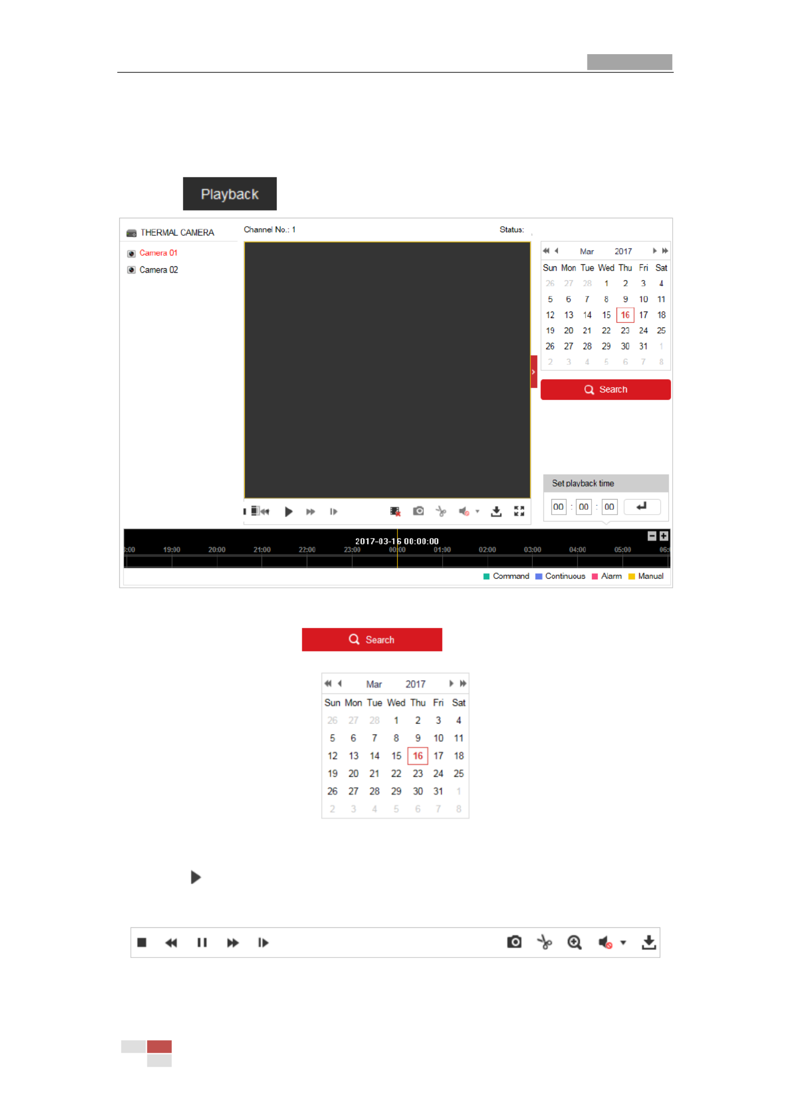
User Manual of Therm Network Positioning system al
© Hikvision
31
4.5.1 P
P
P
PPl
l
l
llay
ay
ay
ayay B
B
B
B Back
ack
ack
ackack
V
V
V
VVi
i
i
iid
d
d
ddeo F
eo F
eo F
eo Feo Fi
i
i
iil
l
l
lles
es
es
eses
St
St
St
StSteps:
eps:
eps:
eps:eps:
1. Click on the menu bar to enter playback interface.
Figure 4-13 Playback Interface
2. Select the date and click .
Figure 4-14 Search Video
3. Click to play the video files found on this date.
The toolbar on the bottom of Playback interface can be used to control playing process.
Figure 4-15 Playback Toolbar

User Manual of Therm Network Positioning system al
© Hikvision
32
Table 4-5 Description of the buttons
Bu
Bu
Bu
BuButt
tt
tt
tttton
on
on
onon
Oper
Oper
Oper
OperOperat
at
at
atati
i
i
iion
on
on
onon
Bu
Bu
Bu
BuButt
tt
tt
tttton
on
on
onon
Oper
Oper
Oper
OperOperat
at
at
atati
i
i
iion
on
on
onon
Play
Capture a picture
Pause
/
Start/Stop clipping
video files
Stop
/
Audio on and
adjust
volume/Mute
Speed down
Download
Speed up
Playback by frame
/
Enable/Disable
digital zoom
You can choose the file paths locally for downloaded playback video files and pictures in
Local Configuration interface. Please refer to Sec
Sec
Sec
SecSecti
ti
ti
tition
on
on
onon
4.
4.
4.
4.4.1
1
1
1 1 Con
Con
Con
ConConfi
fi
fi
fifigur
gur
gur
gurguri
i
i
iing
ng
ng
ng ng Local
Local
Local
LocalLocal
P
P
P
PParameters
arameters
arameters
arametersarameters
for details.
Drag the progress bar with the mouse to locate the exact playback point. You can also
input the time and click to locate the playback point in the field.
Set
Set
Set
Set Set pl
pl
pl
plplayb
ayb
ayb
aybayback
ack
ack
ackack ti
ti
ti
ti time
me
me
meme
You can also click to zoom out/in the progress bar.
Figure 4-16 Set Playback Time
Figure 4-17 Progress Bar
The different colors of the video on the progress bar stand for the different video types as
shown in Figure 4- . 18
Figure 4-18 Video Types
4.5.2 Downl
Downl
Downl
DownlDownlo
o
o
ooad
ad
ad
adadi
i
i
iin
n
n
nng V
g V
g V
g Vg Vi
i
i
iide
de
de
dedeo Fi
o Fi
o Fi
o Fio Fil
l
l
lles
es
es
eses
St
St
St
StSteps:
eps:
eps:
eps:eps:

User Manual of Therm Network Positioning system al
© Hikvision
34
Figure 4-20 Picture Interface
2. Select the file type of capturing the pictures from the list as timing, alarm, motion, etc.
3. Set the start time and end time. Click . The corresponding picture files will be
Sea
Sea
Sea
SeaSearch
rch
rch
rchrch
listed.
4. Check the checkbox in front of the files that you need to download.
5. Click to download the files.

User Manual of Therm Network Positioning system al
© Hikvision
36
Figure 5-2 Record Parameters
Pre
Pre
Pre
PrePre-re
-re
-re
-re-record:
cord:
cord:
cord:cord:
The time you set to start recording before the scheduled time or the
event. For example, if an alarm triggers recording at 10:00, and the pre-record time
is set as 5 seconds, the positioning system starts to record at 9:59:55.
The Pre-record time can be configured as No Pre-record, 5 s, 10 s, 15 s, 20 s, 25 s,
30 s or not limited.
The pre-record time changes according to the video bitrate.
Pos
Pos
Pos
PosPost
t
t
tt-rec
-rec
-rec
-rec-record:
ord:
ord:
ord:ord:
The time you set to stop recording after the scheduled time or the
event. For example, if an alarm triggered recording ends at 11:00, and the
post-record time is set as 5 seconds, the positioning system records until
11:00:05.
The Post-record time can be configured as 5 s, 10 s, 30 s, 1 min, 2 min, 5 min or
10 min.
St
St
St
StStream
ream
ream
ream ream T
T
T
TType
ype
ype
ypeype: You can select the stream type for recording; Main Stream, Sub
Stream and Third Stream are selectable. If you select the sub stream, you can
record for a longer time with the same storage capacity.
The Pre-record and Post-record parameters vary depending on the models of
positioning system.
4. Click to save the advanced setting.
OK
OK
OK
OKOK
5. Select a Record Type. The record type can be Continuous, Motion, Alarm, Motion |
Alarm, Motion & Alarm, and Event.
Normal: If you select Continuous, the video will be recorded automatically
according to the time of the schedule.
Record Triggered by Motion Detection: If you select Motion, the video will be
recorded when the motion is detected. Besides configuring the recording schedule,
you have to set the motion detection area and check the checkbox of T
T
T
TTr
r
r
rri
i
i
iigg
gg
gg
gggger
er
er
er er
Channel
Channel
Channel
ChannelChannel in the Linkage Method of Motion Detection settings interface. For detailed
information, please refer to Section .
Mot
Mot
Mot
MotMoti
i
i
iion Det
on Det
on Det
on Deton Detect
ect
ect
ectecti
i
i
iion
on
on
onon
Record Triggered by Alarm: If you select Alarm, the video will be recorded when
the alarm is triggered via the external alarm input channels. Besides configuring

User Manual of Therm Network Positioning system al
© Hikvision
37
the recording schedule, you have to set the Alarm Type and check the checkbox of
T
T
T
TTri
ri
ri
ririgger
gger
gger
ggergger Channel
Channel
Channel
Channel Channel in the Linkage Method of Alarm Input settings interface. For
detailed information, please refer to Section .
Al
Al
Al
AlAlarm Inp
arm Inp
arm Inp
arm Inparm Input
ut
ut
utut
Record Triggered by Motion & Alarm: If you select Motion & Alarm, the video will
be recorded when the motion and alarm are triggered at the same time. Besides
configuring the recording schedule, you have to configure the settings on the
Motion Detection and Alarm Input settings interfaces.
Record Triggered by Motion | Alarm: If you select Motion | Alarm, the video will be
recorded when the external alarm is triggered or the motion is detected. Besides
configuring the recording schedule, you have to configure the settings on the
Motion Detection and Alarm Input settings interfaces.
Record Triggered by VCA events: If you select VCA, the video will be recorded
when the either of the VCA events is triggered. Besides configuring the recording
schedule, you have to configure the settings on the VCA interface.
VCA function varies depending on the models of positioning system.
Record Triggered by Event: If you select to record by event, the video will be
recorded when any of the events is triggered.
6. Click to save the settings.
5.
5.
5.
5.5.1
1
1
11.
.
.
..2
2
2
22 C
C
C
CCon
on
on
ononfi
fi
fi
fifigur
gur
gur
gurguri
i
i
iing
ng
ng
ngng
Capt
Capt
Capt
CaptCapture
ure
ure
ure ure Sch
Sch
Sch
SchSchedu
edu
edu
eduedul
l
l
lle
e
e
ee
Pu
Pu
Pu
PuPurpose:
rpose:
rpose:
rpose:rpose:
You can configure the scheduled snapshot and event-triggered snapshot. The captured
picture can be stored in the local storage or network storage.
St
St
St
StSteps:
eps:
eps:
eps:eps:
1. Enter the Snapshot settings interface:
Conf
Conf
Conf
ConfConfigu
igu
igu
iguigurati
rati
rati
ratiration
on
on
onon > St
> St
> St
> St > Storage > St
orage > St
orage > St
orage > Storage > Storag
orag
orag
oragorage Set
e Set
e Set
e Sete Setti
ti
ti
titings
ngs
ngs
ngs ngs > Capture
> Capture
> Capture
> Capture> Capture

User Manual of Therm Network Positioning system al
© Hikvision
38
Figure 5-3 Snapshot Settings
2. Click to enter the Capture Schedule interface.
3. Select the timeline of a certain day, click and drag the left button of the mouse to
set the capture schedule (the start time and end time of the recording task).
4. After you set the scheduled task, you can click and copy the task to other
days (optional).
5. After setting the capture schedule, you can click a capture segment to display the
segment capture settings interface to edit the segment capture parameters.
(optional)
Figure 5-4 Segment Snapshot Settings
6. Click to enter the advanced setting interface. You can select the
stream type of the capture.
7. Click to enter the Capture Parameters Interface.
8. Check the checkbox to enable continuous snapshot,
En
En
En
EnEnabl
abl
abl
ablable
e
e
e e Ti
Ti
Ti
TiTiming
ming
ming
ming ming Snap
Snap
Snap
SnapSnapshot
shot
shot
shotshot
and configure the schedule of timing snapshot. Check the Enabl
Enabl
Enabl
EnablEnable
e
e
e e
Event
Event
Event
EventEvent-t
-t
-t
-t-tri
ri
ri
ririgge
gge
gge
ggeggered Snapsh
red Snapsh
red Snapsh
red Snapshred Snapshot
ot
ot
otot checkbox to enable event-triggered snapshot.
9. Select the format, resolution, quality of the snapshot.
10. Set the time interval between two snapshots.
11. Click to save the settings.
Upl
Upl
Upl
UplUploa
oa
oa
oaoading
ding
ding
dingding to
to
to
to to FTP
FTP
FTP
FTP FTP
Please make sure that the FTP server is online.
You can follow below configuration instructions to upload the snapshots to FTP.
Upl
Upl
Upl
UplUpload co
oad co
oad co
oad cooad conti
nti
nti
ntintinuo
nuo
nuo
nuonuous sn
us sn
us sn
us snus snapsho
apsho
apsho
apshoapshots t
ts t
ts t
ts tts to FTP
o FTP
o FTP
o FTPo FTP
St
St
St
StSteps:
eps:
eps:
eps:eps:
1) Configure the FTP settings and check checkbox in FTP Settings
Upl
Upl
Upl
UplUplo
o
o
ooad
ad
ad
ad ad P
P
P
PPi
i
i
iicture
cture
cture
cturecture
interface. Please refer to for more details
Sect
Sect
Sect
SectSecti
i
i
iion 7
on 7
on 7
on 7on 7.
.
.
..1.
1.
1.
1.1.2
2
2
22 Conf
Conf
Conf
Conf Config
ig
ig
igiguri
uri
uri
uriuring FTP
ng FTP
ng FTP
ng FTP ng FTP Set
Set
Set
SetSetti
ti
ti
titings
ngs
ngs
ngsngs
to configure FTP parameters.
2) Check the checkbox.
Enabl
Enabl
Enabl
EnablEnable Ti
e Ti
e Ti
e Tie Timing S
ming S
ming S
ming Sming Snapsho
napsho
napsho
napshonapshot
t
t
tt
3) Click to set the snapshot schedule. Refer to
Edi
Edi
Edi
EdiEdit
t
t
tt Se
Se
Se
SeSecti
cti
cti
ctiction
on
on
onon
5.
5.
5.
5.5.2.
2.
2.
2.2.1
1
1
11
Confi
Confi
Confi
ConfiConfigur
gur
gur
gurguring
ing
ing
ing ing
Mot
Mot
Mot
MotMoti
i
i
iion Dete
on Dete
on Dete
on Deteon Detecti
cti
cti
ctiction
on
on
onon.

User Manual of Therm Network Positioning system al
© Hikvision
40
Proper configuration of all passwords and other security settings is the
responsibility of the installer and/or end-user.
4. Click to add the network disk.
After having saved successfully, you need to reboot the positioning system to activate
the settings.
Ini
Ini
Ini
IniInit
t
t
tti
i
i
iial
al
al
alali
i
i
iize t
ze t
ze t
ze tze the add
he add
he add
he addhe added n
ed n
ed n
ed ned network
etwork
etwork
etworketwork d
d
d
d dis
is
is
isisk.
k.
k.
k.k.
1. Enter the HDD settings interface (Conf
Conf
Conf
ConfConfi
i
i
iigurat
gurat
gurat
guratgurati
i
i
iion
on
on
on on >
>
>
> > St
St
St
StStorage
orage
orage
orageorage
>
>
>
> > St
St
St
StStorage
orage
orage
orageorage
Man
Man
Man
ManManagement
agement
agement
agement agement >
>
>
> >
HDD
HDD
HDD
HDD HDD Man
Man
Man
ManManagement
agement
agement
agementagement), in which you can view the capacity, free space, status, type and
property of the disk.
Figure 5-6 Storage Management Interface
2. If the status of the disk is , check the corresponding checkbox to select the
Un
Un
Un
Un Unin
in
in
inini
i
i
iiti
ti
ti
titial
al
al
alali
i
i
iize
ze
ze
zezed
d
d
dd
disk and click Format
Format
Format
FormatFormat to start initializing the disk.
3. When the initialization completed, the status of disk will become as shown in
Normal
Normal
Normal
Normal Normal
Figure 5-7
.
.
.
..
Figure 5-7 View Disk Status
Defi
Defi
Defi
DefiDefine
ne
ne
nene the
the
the
the the Quo
Quo
Quo
Quo Quota fo
ta fo
ta fo
ta fota for Record and
r Record and
r Record and
r Record andr Record and Pi
Pi
Pi
Pi Pictu
ctu
ctu
ctuctures
res
res
resres
1. Input the quota percentage for picture and for record.
2. Click Save
Save
Save
Save Save and refresh the browser page to activate the settings.

User Manual of Therm Network Positioning system al
© Hikvision
41
Figure 5-8 Quota Settings
Up to 8 NAS disks can be connected to the positioning system.
To initialize and use the memory card after insert it to the positioning system, please
refer to the steps of NAS disk initialization
5.
5.
5.
5.5.2
2
2
22 B
B
B
BBa
a
a
aasi
si
si
sisic Even
c Even
c Even
c Evenc Event
t
t
tt Con
Con
Con
Con Conf
f
f
ffi
i
i
iigur
gur
gur
gurgurat
at
at
atati
i
i
iion
on
on
onon
Pu
Pu
Pu
PuPurpo
rpo
rpo
rporpose:
se:
se:
se:se:
This section explains how to configure the network positioning system to respond to
alarm events, including motion detection, video tampering alarm input, alarm output and
exception. These events can trigger the alarm actions, such as Send Email, Notify
Surveillance Center, etc.
For example, when motion detection is triggered, the network positioning system sends a
notification to an e-mail address.
On the event configuration page, click to show the PTZ control panel or click to
hide it.
Click the direction buttons to control the pan/tilt movements.
Click the zoom/iris/focus buttons to realize lens control.
The functions vary depending on the models of positioning system.
5.2.1 Conf
Conf
Conf
ConfConfi
i
i
iigu
gu
gu
guguri
ri
ri
ririn
n
n
nng M
g M
g M
g Mg Mot
ot
ot
ototi
i
i
iio
o
o
oon
n
n
n n Det
Det
Det
DetDetec
ec
ec
ecect
t
t
tti
i
i
iio
o
o
oon
n
n
nn
Pu
Pu
Pu
PuPurpo
rpo
rpo
rporpose:
se:
se:
se:se:
Motion detection is a feature which can trigger alarm actions and actions of recording
videos when the motion occurred in the surveillance scene.
St
St
St
StSteps
eps
eps
epseps:
:
:
::
1. Enter the motion detection setting interface:
Conf
Conf
Conf
ConfConfi
i
i
iigura
gura
gura
guragurati
ti
ti
tition >
on >
on >
on > on > Event
Event
Event
EventEvent > B
> B
> B
> B > Basi
asi
asi
asiasic
c
c
cc Event
Event
Event
Event Event > Mot
> Mot
> Mot
> Mot > Moti
i
i
iion Det
on Det
on Det
on Deton Dete
e
e
eecti
cti
cti
ctiction
on
on
on on
2. Select the channel to set the motion detection.
3. Check the checkbox of the to enable this function.
Enabl
Enabl
Enabl
Enabl Enable M
e M
e M
e Me Mot
ot
ot
ototi
i
i
iion De
on De
on De
on Deon Detect
tect
tect
tecttecti
i
i
iio
o
o
oon
n
n
nn

User Manual of Therm Network Positioning system al
© Hikvision
42
You can check the Enabl
Enabl
Enabl
EnablEnable
e
e
e e Dy
Dy
Dy
DyDynam
nam
nam
namnamic
ic
ic
icic
Analy
Analy
Analy
AnalyAnalysi
si
si
sisis
s
s
s s for
for
for
for for M
M
M
MMoti
oti
oti
otiotion
on
on
onon checkbox if you want the
detected object get marked with rectangle in the live view.
4. Select the configuration mode as and set the corresponding motion
Normal
Normal
Normal
NormalNormal or Ex
Ex
Ex
ExExpert
pert
pert
pertpert
detection parameters.
Normal
Normal
Normal
Normal Normal
Figure 5-9 Motion Detection Settings-Normal
St
St
St
StSteps:
eps:
eps:
eps:eps:
(1) Click and drag the mouse on the live video image to draw a motion
detection area.
(2) Click to finish drawing.
You can draw up to 8 motion detection areas on the same image.
You can click to clear all of the areas.
(3) Move the slider to set the
sensitivity of the detection.
Expe
Expe
Expe
ExpeExpert
rt
rt
rt rt

User Manual of Therm Network Positioning system al
© Hikvision
43
Figure 5-10 Motion Detection Settings-Expert
Steps:
(1) Set the Sch
Sch
Sch
SchSchedul
edul
edul
eduledule
e
e
ee Image Set
Image Set
Image Set
Image Set Image Setti
ti
ti
titin
n
n
nngs
gs
gs
gsgs, there are and
OFF
OFF
OFF
OFFOFF, A
A
A
AAuto
uto
uto
utouto-S
-S
-S
-S-Swit
wit
wit
witwitch
ch
ch
ch ch
Sch
Sch
Sch
SchSchedul
edul
edul
eduleduled
ed
ed
eded-Swi
-Swi
-Swi
-Swi-Switc
tc
tc
tctch
h
h
hh selectable. If the schedule image switch mode is enabled, you
can configure the detection rule for the day and night separately.
OFF
OFF
OFF
OFFOFF
:
:
:
::
Disable the day and night switch.
Au
Au
Au
AuAuto
to
to
toto-S
-S
-S
-S-Sw
w
w
wwi
i
i
iit
t
t
ttch:
ch:
ch:
ch:ch:
Switch the day and night mode according to the illumination
automatically.
Sch
Sch
Sch
SchSchedul
edul
edul
eduleduled
ed
ed
eded-Swi
-Swi
-Swi
-Swi-Switc
tc
tc
tctch:
h:
h:
h:h:
Switch to the day mode at 6:00 a.m., and switch to the night
mode at 18:00 p.m..
(2) Select to configure in the dropdown list. Area No.
Area No.
Area No.
Area No.Area No.
(3) Set the values of sensitivity and proportion of object on area.
Sen
Sen
Sen
SenSensi
si
si
sisiti
ti
ti
titiv
v
v
vvi
i
i
iity
ty
ty
tyty:
:
:
::
The greater the value is, the easier the alarm will be triggered.
Pro
Pro
Pro
ProPropor
por
por
porporti
ti
ti
tition of
on of
on of
on ofon of O
O
O
O Obje
bje
bje
bjebject o
ct o
ct o
ct oct on Area
n Area
n Area
n Arean Area:
:
:
::
When the size proportion of the moving object
exceeds the predefined value, the alarm will be triggered. The less the value is,
the easier the alarm will be triggered.
5. Set the A
A
A
AArmin
rmin
rmin
rminrming Sche
g Sche
g Sche
g Scheg Schedul
dul
dul
duldule
e
e
ee for Motion Detection.
(1) Click tab to enter the arming schedule setting interface.

User Manual of Therm Network Positioning system al
© Hikvision
44
Figure 5-11 Arming Schedule
(2) Select the timeline of a certain day, click and drag the mouse to set the arming
schedule (the start time and end time of the arming task).
(3) After you set the scheduled task, you can click and copy the task to other
days (optional).
Figure 5-12 Arming Time Schedule
(4) After setting the arming schedule, you can click a segment to display the
segment arming settings interface to edit the segment record parameters
(optional).
Figure 5-13 Segment Arming Settings
(5) Click to save the settings.

User Manual of Therm Network Positioning system al
© Hikvision
45
The time of each period cannot be overlapped. Up to 8 periods can be configured for
each day.
6. Set the Al
Al
Al
AlAlarm Act
arm Act
arm Act
arm Actarm Actio
io
io
ioions
ns
ns
nsns for Motion Detection.
Click tab to enter the interface.
Lin
Lin
Lin
LinLink
k
k
kkage Met
age Met
age Met
age Metage Method
hod
hod
hodhod
You can specify the linkage method when an event occurs. The following contents are
about how to configure the different types of linkage method.
Figure 5-14 Linkage Method
Check the checkbox to select the linkage method. Notify Surveillance Center,
Send Email, Upload to FTP/Memory/NAS, Trigger Alarm Output and Trigger
Recording are selectable.
Noti
Noti
Noti
NotiNotif
f
f
ffy S
y S
y S
y Sy Surv
urv
urv
urvurveil
eil
eil
eileill
l
l
llance Cent
ance Cent
ance Cent
ance Centance Center
er
er
erer
Send an exception or alarm signal to remote management software when an
event occurs.
Se
Se
Se
SeSend Email
nd Email
nd Email
nd Emailnd Email
Send an email with alarm information to a user or users when an event occurs.
To send the Email when an event occurs, you need to refer to S
S
S
SSect
ect
ect
ectecti
i
i
iion
on
on
onon Conf
Conf
Conf
ConfConfi
i
i
iiguri
guri
guri
guriguring
ng
ng
ng ng
Email
Email
Email
EmailEmail S
S
S
S Sett
ett
ett
ettetti
i
i
iings
ngs
ngs
ngsngs
to set the Email parameters.
Upl
Upl
Upl
UplUpload
oad
oad
oad oad to
to
to
toto FT
FT
FT
FT FTP
P
P
PP/Memory
/Memory
/Memory
/Memory/Memory/NA
/NA
/NA
/NA/NAS
S
S
S S
Capture the image when an alarm is triggered and upload the picture to a FTP
server.

User Manual of Therm Network Positioning system al
© Hikvision
46
You need a FTP server and set FTP parameters first. Refer to Sect
Sect
Sect
SectSecti
i
i
iion
on
on
on on Conf
Conf
Conf
ConfConfi
i
i
iigur
gur
gur
gurguri
i
i
iing
ng
ng
ng ng
FTP Se
FTP Se
FTP Se
FTP SeFTP Sett
tt
tt
tttti
i
i
iings
ngs
ngs
ngsngs
for setting FTP parameters.
T
T
T
TTri
ri
ri
ririgge
gge
gge
ggegger A
r A
r A
r Ar Ala
la
la
lalarm Outpu
rm Outpu
rm Outpu
rm Outpurm Output
t
t
t t
Trigger one or more external alarm outputs when an event occurs.
To trigger an alarm output when an event occurs, please refer to Secti
Secti
Secti
SectiSection
on
on
on on 5.
5.
5.
5.5.2.
2.
2.
2.2.4
4
4
4 4
Conf
Conf
Conf
ConfConfi
i
i
iiguri
guri
guri
gurigurin
n
n
nng A
g A
g A
g Ag Ala
la
la
lalarm Outpu
rm Outpu
rm Outpu
rm Outpurm Output
t
t
tt to set the alarm output parameters.
T
T
T
TTri
ri
ri
ririgge
gge
gge
ggegger Recordi
r Recordi
r Recordi
r Recordir Recording
ng
ng
ng ng
Record a video when an event occurs.
You have to set the recording schedule to realize this function. Please refer to
Sec
Sec
Sec
SecSecti
ti
ti
tition
on
on
on on 5.
5.
5.
5.5.1.
1.
1.
1.1.1
1
1
11
Conf
Conf
Conf
ConfConfig
ig
ig
igiguri
uri
uri
uriuring
ng
ng
ngng
Recordin
Recordin
Recordin
RecordinRecording
g
g
g g Sche
Sche
Sche
ScheSchedul
dul
dul
duldule
e
e
ee
for settings the recording
schedule.
5.
5.
5.
5.5.2
2
2
22.
.
.
..2
2
2
22 C
C
C
CCon
on
on
ononf
f
f
ffi
i
i
iigu
gu
gu
gugur
r
r
rri
i
i
iing
ng
ng
ngng
V
V
V
VVi
i
i
iid
d
d
ddeo
eo
eo
eoeo T
T
T
T Tamper
amper
amper
amperamperi
i
i
iin
n
n
nng
g
g
g g Al
Al
Al
AlAlar
ar
ar
ararm
m
m
m m
Pu
Pu
Pu
PuPurpose
rpose
rpose
rposerpose:
:
:
::
You can configure the positioning system to trigger the alarm actions when the lens is
covered.
St
St
St
StSteps:
eps:
eps:
eps:eps:
1. Enter the Video Tampering settings interface :
Conf
Conf
Conf
ConfConfi
i
i
iigurat
gurat
gurat
guratgurati
i
i
iion
on
on
on on > Event
> Event
> Event
> Event> Event > Bas
> Bas
> Bas
> Bas > Basi
i
i
iic Event
c Event
c Event
c Eventc Event >
>
>
> > V
V
V
VVid
id
id
idideo T
eo T
eo T
eo Teo Tamperi
amperi
amperi
amperiampering
ng
ng
ngng
2. Select the channel to set the video tampering alarm.

User Manual of Therm Network Positioning system al
© Hikvision
48
Figure 5-16 Alarm Input Settings
4. Click tab to enter the arming schedule setting interface. The
arming schedule configuration is the same as the setting of the arming schedule for
motion detection. Refer to
Secti
Secti
Secti
SectiSection
on
on
onon 5.
5.
5.
5.5.2.
2.
2.
2.2.1
1
1
11 Confi
Confi
Confi
Confi Config
g
g
gguri
uri
uri
uriuring
ng
ng
ngng Mot
Mot
Mot
Mot Moti
i
i
iion De
on De
on De
on Deon Detect
tect
tect
tecttecti
i
i
iion
on
on
onon .
5. Click tab to select the linkage method taken for alarm input, including
Notify Surveillance Center, Send Email, Upload to FTP/Memory Card/NAS, Trigger
Alarm Output and Trigger Recording. Refer to Sect
Sect
Sect
SectSecti
i
i
iion
on
on
onon 5.
5.
5.
5.5.2.
2.
2.
2.2.1
1
1
11
Confi
Confi
Confi
ConfiConfiguri
guri
guri
gurigurin
n
n
nng
g
g
g g Mot
Mot
Mot
MotMoti
i
i
iion
on
on
on on
Dete
Dete
Dete
DeteDetecti
cti
cti
ctiction
on
on
onon.
6. You can also choose the PTZ linking for the alarm input. Check the relative checkbox
and select the No. to enable Preset Calling, Patrol Calling or Pattern Calling.
7. You can copy your settings to other alarm inputs.
8. Click to save the settings.
Figure 5-17 Linkage Method

User Manual of Therm Network Positioning system al
© Hikvision
49
5.
5.
5.
5.5.2.
2.
2.
2.2.4
4
4
44 Conf
Conf
Conf
ConfConfi
i
i
iigu
gu
gu
guguri
ri
ri
riring
ng
ng
ngng A
A
A
A Al
l
l
llar
ar
ar
ararm Ou
m Ou
m Ou
m Oum Out
t
t
ttp
p
p
pput
ut
ut
utut
St
St
St
StSteps
eps
eps
epseps:
:
:
::
1. Enter the Alarm Output settings interface:
Conf
Conf
Conf
ConfConfi
i
i
iigurat
gurat
gurat
guratgurati
i
i
iion
on
on
onon> Event
> Event
> Event
> Event> Event > B
> B
> B
> B > Basi
asi
asi
asiasic Even
c Even
c Even
c Evenc Event >
t >
t >
t > t > Al
Al
Al
AlAla
a
a
aarm Outpu
rm Outpu
rm Outpu
rm Outpurm Output
t
t
tt
2. Select one alarm output channel in the
A
A
A
AAl
l
l
llarm Out
arm Out
arm Out
arm Outarm Output
put
put
putput dropdown list.
3. Set a name in for the alarm output
(optional).
4. The time can be set to
Delay
Delay
Delay
DelayDelay 5sec
5sec
5sec
5sec5sec, 1
1
1
110s
0s
0s
0s0sec
ec
ec
ecec, 30s
30s
30s
30s30sec
ec
ec
ecec, 1min
1min
1min
1min1min, 2mi
2mi
2mi
2mi2min
n
n
nn, 5min
5min
5min
5min5min,
,
,
,, 10mi
10mi
10mi
10mi 10min
n
n
nn or Manual
Manual
Manual
Manual Manual.
The delay time refers to the time duration that the alarm output remains in effect after
alarm occurs.
5. Click tab to enter the arming schedule setting interface. The time
schedule configuration is the same as the settings of the arming schedule for motion
detection. Refer to .
S
S
S
S Sect
ect
ect
ectecti
i
i
iion
on
on
onon 5.
5.
5.
5.5.2
2
2
22.
.
.
..1
1
1
11 Confi
Confi
Confi
Confi Configur
gur
gur
gurgurin
in
in
ining Mo
g Mo
g Mo
g Mog Moti
ti
ti
titio
o
o
oon Det
n Det
n Det
n Detn Detecti
ecti
ecti
ectiection
on
on
onon
Figure 5-18 Alarm Output Settings
6. You can copy the settings to other alarm outputs.
7. Click to save the settings.
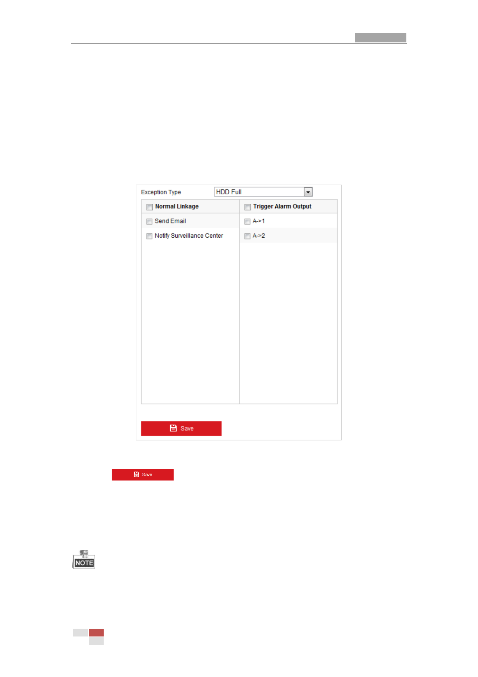
User Manual of Therm Network Positioning system al
© Hikvision
50
5.
5.
5.
5.5.2.
2.
2.
2.2.5
5
5
55 Hand
Hand
Hand
HandHandl
l
l
lli
i
i
iin
n
n
nng Ex
g Ex
g Ex
g Exg Excep
cep
cep
cepcept
t
t
tti
i
i
iio
o
o
oon
n
n
nn
The exception type can be HDD full, HDD error, network disconnected, IP address
conflicted and illegal login to the positioning systems.
St
St
St
StSteps
eps
eps
epseps:
:
:
::
1. Enter the Exception settings interface:
Conf
Conf
Conf
ConfConfi
i
i
iigurat
gurat
gurat
guratgurati
i
i
iion
on
on
onon >
>
>
> > Event
Event
Event
EventEvent > Ba
> Ba
> Ba
> Ba > Basi
si
si
sisic Eve
c Eve
c Eve
c Evec Event
nt
nt
nt nt > Except
> Except
> Except
> Except> Excepti
i
i
iion
on
on
onon
2. Check the checkbox to set the actions taken for the Exception alarm. Refer to S
S
S
SSect
ect
ect
ectecti
i
i
iion
on
on
onon
5.
5.
5.
5.5.2.
2.
2.
2.2.1 Conf
1 Conf
1 Conf
1 Conf1 Confi
i
i
iigu
gu
gu
guguri
ri
ri
riring M
ng M
ng M
ng Mng Mot
ot
ot
ototi
i
i
iion Det
on Det
on Det
on Deton Detec
ec
ec
ececti
ti
ti
tition
on
on
onon.
Figure 5-19 Exception Settings
3. Click to save the settings.
5.
5.
5.
5.5.3
3
3
33 Smar
Smar
Smar
SmarSmart
t
t
tt Eve
Eve
Eve
Eve Event
nt
nt
ntnt
Con
Con
Con
ConConf
f
f
ffi
i
i
iig
g
g
ggu
u
u
uura
ra
ra
rarat
t
t
tti
i
i
iio
o
o
oon
n
n
nn
The functions vary depending on the models of positioning system.

User Manual of Therm Network Positioning system al
© Hikvision
53
The function of dynamic fire source detection can only be enabled for
camera 2.
Fi
Fi
Fi
FiFire and
re and
re and
re and re and Sm
Sm
Sm
SmSmoke
oke
oke
oke oke Detecti
Detecti
Detecti
DetectiDetectio
o
o
oon Mode:
n Mode:
n Mode:
n Mode:n Mode:
1) Select Fire or Smoke, and the system alarms when device is either triggered
by Fire Source Detection or Smoke Detection.
2) Select Fire and Smoke, the system holds when device is triggered by Fire
Source Detection or Smoke Detection. When target is detected by both
rules, the system sends two alarms, otherwise, the system sends single
alarm.
3) Select Double Confirm, the system alarms when device is both triggered by
Fire Source Detection and Smoke Detection.
4) Select Specified Fire Source, and the system alarms when device is triggered
by fire source detection.
5) Select Specified Smoke, and the system alarms when device is triggered by
smoke.
Dete
Dete
Dete
DeteDetecti
cti
cti
ctiction Mode:
on Mode:
on Mode:
on Mode:on Mode: Select detection mode as by Multiple Frame, and the system
alarms with high accuracy. Select detection mode as by Single Frame, and the
system alarms with short delay.
Fi
Fi
Fi
FiFire
re
re
re re Source
Source
Source
Source Source Zoom
Zoom
Zoom
Zoom Zoom Mode:
Mode:
Mode:
Mode:Mode: In Auto mode, the system moves and locates at the fire
source, and then it zooms according to the predefined focus mode. To set the focus
mode, go to Configuration>Advanced Configuration>Image>Channel No.2>Focus
Mode.
Sen
Sen
Sen
SenSensi
si
si
sisiti
ti
ti
titivi
vi
vi
vivity
ty
ty
tyty:
:
:
:: Range [1-100], the smaller the value is, the fire source of lower
temperature can be detected.
Dwell
Dwell
Dwell
DwellDwell
Time(
Time(
Time(
Time(Time(s):
s):
s):
s):s): Range [0-120]. You can set the dwell time of the positioning system
staying the position where detects the fire source when performing auto scan,
patrol, pattern, scheduled task, and park action.
Fi
Fi
Fi
FiFire
re
re
re re Sou
Sou
Sou
SouSour
r
r
rrce
ce
ce
ce ce Z
Z
Z
ZZoom
oom
oom
oom oom R
R
R
RRati
ati
ati
atiatio:
o:
o:
o:o: Set the zoom ratio of the optical channel when it detects
the fire source. In Auto mode, the optical channel changes its zoom ratio until two
channels have the same field of view. In Manual mode, you can set the optical
zoom ratio.
Smoke
Smoke
Smoke
Smoke Smoke Dete
Dete
Dete
DeteDetecti
cti
cti
ctiction:
on:
on:
on:on:
Set the sensitivity of the smoke detection. The greater the value
is, the easier the alarm will be triggered. (reserved)
4. Check the checkbox of Di
Di
Di
DiDisp
sp
sp
spsplay
lay
lay
laylay
Fi
Fi
Fi
FiFire
re
re
re re S
S
S
SSource
ource
ource
ource ource Fram
Fram
Fram
FramFrame
e
e
e e o
o
o
oon
n
n
n n S
S
S
SStream
tream
tream
treamtream to display a red frame
around the fire source on stream when fire occurs. (Optional)
5. Check the checkbox to select the linkage method taken for the alarm input. Refer to
Step 3 in Section 5.2 Configuring Motion Detection.1 . In the field of , you
O
O
O
OOther
ther
ther
ther ther Lin
Lin
Lin
LinLinkage
kage
kage
kagekage
can check the checkbox to enable the alarm output (The alarm output number varies
depending on device ability).
6. Click to save the settings.
Specyfikacje produktu
| Marka: | Hikvision |
| Kategoria: | Kamera monitorująca |
| Model: | DS-2TD6236-50H2L |
Potrzebujesz pomocy?
Jeśli potrzebujesz pomocy z Hikvision DS-2TD6236-50H2L, zadaj pytanie poniżej, a inni użytkownicy Ci odpowiedzą
Instrukcje Kamera monitorująca Hikvision

12 Stycznia 2025
12 Stycznia 2025
12 Stycznia 2025
12 Stycznia 2025
11 Stycznia 2025
7 Stycznia 2025
19 Grudnia 2024
19 Grudnia 2024
19 Grudnia 2024
19 Grudnia 2024
Instrukcje Kamera monitorująca
- Kamera monitorująca Sony
- Kamera monitorująca Samsung
- Kamera monitorująca Tenda
- Kamera monitorująca Motorola
- Kamera monitorująca Stabo
- Kamera monitorująca Logitech
- Kamera monitorująca Xiaomi
- Kamera monitorująca Braun
- Kamera monitorująca Pioneer
- Kamera monitorująca TP-Link
- Kamera monitorująca Philips
- Kamera monitorująca Bosch
- Kamera monitorująca Gigaset
- Kamera monitorująca EZVIZ
- Kamera monitorująca Conceptronic
- Kamera monitorująca Panasonic
- Kamera monitorująca Canon
- Kamera monitorująca Crestron
- Kamera monitorująca Withings
- Kamera monitorująca Asus
- Kamera monitorująca Nedis
- Kamera monitorująca AG Neovo
- Kamera monitorująca Reolink
- Kamera monitorująca Boss
- Kamera monitorująca TRENDnet
- Kamera monitorująca Marquant
- Kamera monitorująca Toshiba
- Kamera monitorująca D-Link
- Kamera monitorująca August
- Kamera monitorująca Niceboy
- Kamera monitorująca Ring
- Kamera monitorująca Garmin
- Kamera monitorująca Imou
- Kamera monitorująca Blaupunkt
- Kamera monitorująca Grundig
- Kamera monitorująca APC
- Kamera monitorująca Honeywell
- Kamera monitorująca BLOW
- Kamera monitorująca Manhattan
- Kamera monitorująca Strong
- Kamera monitorująca Swann
- Kamera monitorująca Kwikset
- Kamera monitorująca Kodak
- Kamera monitorująca Cisco
- Kamera monitorująca ORNO
- Kamera monitorująca Broan
- Kamera monitorująca Moxa
- Kamera monitorująca Synology
- Kamera monitorująca Gembird
- Kamera monitorująca ZTE
- Kamera monitorująca Turing
- Kamera monitorująca Lindy
- Kamera monitorująca Minox
- Kamera monitorująca Zebra
- Kamera monitorująca DSC
- Kamera monitorująca JVC
- Kamera monitorująca ZyXEL
- Kamera monitorująca Trust
- Kamera monitorująca LogiLink
- Kamera monitorująca Furrion
- Kamera monitorująca Linksys
- Kamera monitorująca Google
- Kamera monitorująca Digitus
- Kamera monitorująca Vimar
- Kamera monitorująca V-TAC
- Kamera monitorująca Dahua Technology
- Kamera monitorująca Schneider
- Kamera monitorująca Eufy
- Kamera monitorująca Ricoh
- Kamera monitorująca Emos
- Kamera monitorująca AVMATRIX
- Kamera monitorująca Renkforce
- Kamera monitorująca Rollei
- Kamera monitorująca Marshall
- Kamera monitorująca Perel
- Kamera monitorująca Somfy
- Kamera monitorująca Uniden
- Kamera monitorująca Netgear
- Kamera monitorująca Thomson
- Kamera monitorująca DiO
- Kamera monitorująca Velleman
- Kamera monitorująca Ferguson
- Kamera monitorująca DataVideo
- Kamera monitorująca Delta Dore
- Kamera monitorująca Pyle
- Kamera monitorująca Intellinet
- Kamera monitorująca CRUX
- Kamera monitorująca Setti+
- Kamera monitorująca Waeco
- Kamera monitorująca Vivotek
- Kamera monitorująca Vtech
- Kamera monitorująca Speco Technologies
- Kamera monitorująca EtiamPro
- Kamera monitorująca Edimax
- Kamera monitorująca Petcube
- Kamera monitorująca ION
- Kamera monitorująca First Alert
- Kamera monitorująca AirLive
- Kamera monitorująca Maginon
- Kamera monitorująca EnGenius
- Kamera monitorująca SPC
- Kamera monitorująca Planet
- Kamera monitorująca Brilliant
- Kamera monitorująca Genie
- Kamera monitorująca LevelOne
- Kamera monitorująca Axis
- Kamera monitorująca Sanyo
- Kamera monitorująca Lorex
- Kamera monitorująca Control4
- Kamera monitorująca Milesight
- Kamera monitorująca Aluratek
- Kamera monitorująca Abus
- Kamera monitorująca Elro
- Kamera monitorująca Olympia
- Kamera monitorująca Hama
- Kamera monitorująca Marmitek
- Kamera monitorująca Ubiquiti Networks
- Kamera monitorująca Western Digital
- Kamera monitorująca Netatmo
- Kamera monitorująca Schwaiger
- Kamera monitorująca Promise Technology
- Kamera monitorująca GVI Security
- Kamera monitorująca AVer
- Kamera monitorująca ZKTeco
- Kamera monitorująca Netis
- Kamera monitorująca Extech
- Kamera monitorująca Denver
- Kamera monitorująca Anker
- Kamera monitorująca Allnet
- Kamera monitorująca Marshall Electronics
- Kamera monitorująca Orion
- Kamera monitorująca Yale
- Kamera monitorująca SereneLife
- Kamera monitorująca Ernitec
- Kamera monitorująca AVerMedia
- Kamera monitorująca MEE Audio
- Kamera monitorująca Genius
- Kamera monitorująca Trevi
- Kamera monitorująca Technaxx
- Kamera monitorująca Atlona
- Kamera monitorująca Hanwha
- Kamera monitorująca Overmax
- Kamera monitorująca Quantum
- Kamera monitorująca Y-cam
- Kamera monitorująca Grandstream
- Kamera monitorująca Raymarine
- Kamera monitorująca Powerfix
- Kamera monitorująca Avanti
- Kamera monitorująca Ikan
- Kamera monitorująca Alecto
- Kamera monitorująca Avidsen
- Kamera monitorująca JUNG
- Kamera monitorująca Burg Wächter
- Kamera monitorująca Foscam
- Kamera monitorująca Lumens
- Kamera monitorująca Monacor
- Kamera monitorująca Dörr
- Kamera monitorująca M-e
- Kamera monitorująca EVE
- Kamera monitorująca Smartwares
- Kamera monitorująca Adj
- Kamera monitorująca Qian
- Kamera monitorująca Arenti
- Kamera monitorująca Elmo
- Kamera monitorująca Vitek
- Kamera monitorująca Alfatron
- Kamera monitorująca UniView
- Kamera monitorująca Clas Ohlson
- Kamera monitorująca Laserliner
- Kamera monitorująca Megasat
- Kamera monitorująca REVO
- Kamera monitorująca BZBGear
- Kamera monitorująca BirdDog
- Kamera monitorująca KJB Security Products
- Kamera monitorująca HiLook
- Kamera monitorująca Profile
- Kamera monitorująca Aldi
- Kamera monitorująca Aritech
- Kamera monitorująca Acti
- Kamera monitorująca ACME
- Kamera monitorująca Flamingo
- Kamera monitorująca Caliber
- Kamera monitorująca Eminent
- Kamera monitorująca Sitecom
- Kamera monitorująca Exibel
- Kamera monitorująca Fortinet
- Kamera monitorująca KlikaanKlikuit
- Kamera monitorująca Trebs
- Kamera monitorująca Ednet
- Kamera monitorująca Steren
- Kamera monitorująca Flir
- Kamera monitorująca Buffalo
- Kamera monitorująca Arlo
- Kamera monitorująca Nest
- Kamera monitorująca Siedle
- Kamera monitorująca Hive
- Kamera monitorująca Switel
- Kamera monitorująca Chacon
- Kamera monitorująca InFocus
- Kamera monitorująca Hombli
- Kamera monitorująca Naxa
- Kamera monitorująca Konig
- Kamera monitorująca Valueline
- Kamera monitorująca BRK
- Kamera monitorująca QSC
- Kamera monitorująca Xavax
- Kamera monitorująca Vaddio
- Kamera monitorująca Gira
- Kamera monitorująca Interlogix
- Kamera monitorująca Boyo
- Kamera monitorująca IC Intracom
- Kamera monitorująca Iget
- Kamera monitorująca EverFocus
- Kamera monitorująca Adesso
- Kamera monitorująca Satel
- Kamera monitorująca POSline
- Kamera monitorująca Notifier
- Kamera monitorująca Hawking Technologies
- Kamera monitorująca Friedland
- Kamera monitorująca Nexxt
- Kamera monitorująca Monoprice
- Kamera monitorująca Watec
- Kamera monitorująca Beafon
- Kamera monitorująca Chuango
- Kamera monitorująca ETiger
- Kamera monitorująca Videcon
- Kamera monitorująca INSTAR
- Kamera monitorująca Provision ISR
- Kamera monitorująca Aqara
- Kamera monitorująca Advantech
- Kamera monitorująca Digital Watchdog
- Kamera monitorująca Ganz
- Kamera monitorująca AViPAS
- Kamera monitorująca ClearOne
- Kamera monitorująca Ebode
- Kamera monitorująca Oplink
- Kamera monitorująca Sonic Alert
- Kamera monitorująca Linear PRO Access
- Kamera monitorująca Summer Infant
- Kamera monitorująca SMC
- Kamera monitorująca Topica
- Kamera monitorująca Kogan
- Kamera monitorująca Iiquu
- Kamera monitorująca Verint
- Kamera monitorująca Brinno
- Kamera monitorująca Rostra
- Kamera monitorująca Caddx
- Kamera monitorująca Spyclops
- Kamera monitorująca EKO
- Kamera monitorująca Kguard
- Kamera monitorująca Woonveilig
- Kamera monitorująca Mobi
- Kamera monitorująca Surveon
- Kamera monitorująca Hollyland
- Kamera monitorująca Epcom
- Kamera monitorująca Indexa
- Kamera monitorująca Lutec
- Kamera monitorująca Whistler
- Kamera monitorująca ClearView
- Kamera monitorująca VideoComm
- Kamera monitorująca IMILAB
- Kamera monitorująca 3xLOGIC
- Kamera monitorująca Pelco
- Kamera monitorująca Leviton
- Kamera monitorująca Inkovideo
- Kamera monitorująca Pentatech
- Kamera monitorująca Weldex
- Kamera monitorująca SecurityMan
- Kamera monitorująca Canyon
- Kamera monitorująca CNB Technology
- Kamera monitorująca Tapo
- Kamera monitorująca Aigis
- Kamera monitorująca Exacq
- Kamera monitorująca Brickcom
- Kamera monitorująca Laxihub
- Kamera monitorująca Securetech
- Kamera monitorująca EFB Elektronik
- Kamera monitorująca NetMedia
- Kamera monitorująca Videotec
- Kamera monitorująca Illustra
- Kamera monitorująca Nivian
- Kamera monitorująca E-bench
- Kamera monitorująca Syscom
- Kamera monitorująca Tecno
- Kamera monitorująca Night Owl
- Kamera monitorująca Guardzilla
- Kamera monitorująca Astak
- Kamera monitorująca Blink
- Kamera monitorująca Milestone Systems
- Kamera monitorująca Zavio
- Kamera monitorująca Campark
- Kamera monitorująca IPX
- Kamera monitorująca Dedicated Micros
- Kamera monitorująca Hamlet
- Kamera monitorująca Annke
- Kamera monitorująca AVTech
- Kamera monitorująca Qoltec
- Kamera monitorująca Approx
- Kamera monitorująca Digimerge
- Kamera monitorująca Wisenet
- Kamera monitorująca Infortrend
- Kamera monitorująca Epiphan
- Kamera monitorująca Mach Power
- Kamera monitorująca Compro
- Kamera monitorująca Aida
- Kamera monitorująca Ikegami
- Kamera monitorująca Accsoon
- Kamera monitorująca Vimtag
- Kamera monitorująca Gewiss
- Kamera monitorująca Alula
- Kamera monitorująca Insteon
- Kamera monitorująca Costar
- Kamera monitorująca ALC
- Kamera monitorująca Security Labs
- Kamera monitorująca Comtrend
- Kamera monitorująca Seneca
- Kamera monitorująca Avigilon
- Kamera monitorująca American Dynamics
- Kamera monitorująca Vosker
- Kamera monitorująca Sentry360
- Kamera monitorująca Bea-fon
- Kamera monitorująca Owltron
- Kamera monitorująca Enabot
- Kamera monitorująca Luis Energy
- Kamera monitorująca Sir Gawain
- Kamera monitorująca VisorTech
- Kamera monitorująca Atlantis Land
- Kamera monitorująca B & S Technology
- Kamera monitorująca I3International
- Kamera monitorująca IDIS
- Kamera monitorująca Ecobee
- Kamera monitorująca Conbrov
- Kamera monitorująca HuddleCamHD
- Kamera monitorująca Mobotix
- Kamera monitorująca IOIO
- Kamera monitorująca BIRDFY
- Kamera monitorująca I-PRO
- Kamera monitorująca DVDO
- Kamera monitorująca TCP
- Kamera monitorująca Bolin Technology
- Kamera monitorująca Nextech
Najnowsze instrukcje dla Kamera monitorująca

28 Stycznia 2025
25 Stycznia 2025
17 Stycznia 2025
15 Stycznia 2025

13 Stycznia 2025

13 Stycznia 2025
13 Stycznia 2025
12 Stycznia 2025
12 Stycznia 2025
12 Stycznia 2025