Instrukcja obsługi Hikvision DS-2CE10KF3T-E
Hikvision
Kamera monitorująca
DS-2CE10KF3T-E
Przeczytaj poniżej 📖 instrukcję obsługi w języku polskim dla Hikvision DS-2CE10KF3T-E (18 stron) w kategorii Kamera monitorująca. Ta instrukcja była pomocna dla 7 osób i została oceniona przez 2 użytkowników na średnio 4.5 gwiazdek
Strona 1/18

3K ColorVu
Bullet & Turret Camera
User Manual
User Manual
Thank you for purchasing our product. If there are any
quesons, or requests, do not hesitate to contact the
dealer.
This manual applies to the models below:
Type
Model
Type I Camera
DS- - 2CE12KF3T E
DS- 2CE12KF3T
Type CameraII
DS- - 2CE10KF3T E
DS- 2CE10KF3T
Type III Camera
DS- - 2CE72KF3T E
DS- 2CE72KF3T
This manual may contain several technical mistakes or
prinng errors, and the content is subject to change
without noce. The updates will be added to the new
version of this manual. We will readily improve or update
the products or procedures described in the manual.
0 1020100202012

© 2020 Hangzhou Hikvision Digital Technology Co., Ltd.
All rights reserved.
About this Manual
The Manual includes instrucons for using and managing
the Product. Pictures, charts, images and all other
informaon hereinaer are for descripon and
explanaon only. The informaon contained in the
Manual is subject to change, without noce, due to
rmware updates or other reasons. Please nd the latest
version of this Manual at the Hikvision website
(hps://www.hikvision.com/).
Please use this Manual with the guidance and assistance
of professionals trained in supporng the Product.
Trademarks
and other Hikvision’s trademarks and
logos are the properes of Hikvision in various
jurisdicons.
Other trademarks and logos menoned are the properes
of their respecve owners.
Disclaimer
TO THE MAXIMUM EXTENT PERMITTED BY APPLICABLE
LAW, THIS MANUAL AND THE PRODUCT DESCRIBED, WITH
ITS HARDWARE, SOFTWARE AND FIRMWARE, ARE
PROVIDED “AS IS” AND “WITH ALL FAULTS AND ERRORS”.
HIKVISION MAKES NO WARRANTIES, EXPRESS OR IMPLIED,
INCLUDING WITHOUT LIMITATION, MERCHANTABILITY,
SATISFACTORY QUALITY, OR FITNESS FOR A PARTICULAR
PURPOSE. THE USE OF THE PRODUCT BY YOU IS AT YOUR
OWN RISK. IN NO EVENT WILL HIKVISION BE LIABLE TO
YOU FOR ANY SPECIAL, CONSEQUENTIAL, INCIDENTAL, OR
INDIRECT DAMAGES, INCLUDING, AMONG OTHERS,
DAMAGES FOR LOSS OF BUSINESS PROFITS, BUSINESS
INTERRUPTION, OR LOSS OF DATA, CORRUPTION OF
SYSTEMS, OR LOSS OF DOCUMENTATION, WHETHER
BASED ON BREACH OF CONTRACT, TORT (INCLUDING
NEGLIGENCE), PRODUCT LIABILITY, OR OTHERWISE, IN
CONNECTION WITH THE USE OF THE PRODUCT, EVEN IF
HIKVISION HAS BEEN ADVISED OF THE POSSIBILITY OF
SUCH DAMAGES OR LOSS.
YOU ACKNOWLEDGE THAT THE NATURE OF THE INTERNET
PROVIDES FOR INHERENT SECURITY RISKS, AND
HIKVISION SHALL NOT TAKE ANY RESPONSIBILITIES FOR
ABNORMAL OPERATION, PRIVACY LEAKAGE OR OTHER
DAMAGES RESULTING FROM CYBER ATTACK, HACKER -
ATTACK, VIRUS INFECTION, OR OTHER INTERNET
SECURITY RISKS; HOWEVER, HIKVISION WILL PROVIDE
TIMELY TECHNICAL SUPPORT IF REQUIRED.
YOU AGREE TO USE THIS PRODUCT IN COMPLIANCE WITH
ALL APPLICABLE LAWS, AND YOU ARE SOLELY
RESPONSIBLE FOR ENSURING THAT YOUR USE CONFORMS
TO THE APPLICABLE LAW. ESPECIALLY, YOU ARE
RESPONSIBLE, FOR USING THIS PRODUCT IN A MANNER
THAT DOES NOT INFRINGE ON THE RIGHTS OF THIRD
PARTIES, INCLUDING WITHOUT LIMITATION, RIGHTS OF
PUBLICITY, INTELLECTUAL PROPERTY RIGHTS, OR DATA
PROTECTION AND OTHER PRIVACY RIGHTS. YOU SHALL
NOT USE THIS PRODUCT FOR ANY PROHIBITED END USES, -
INCLUDING THE DEVELOPMENT OR PRODUCTION OF
WEAPONS OF MASS DESTRUCTION, THE DEVELOPMENT
OR PRODUCTION OF CHEMICAL OR BIOLOGICAL
WEAPONS, ANY ACTIVITIES IN THE CONTEXT RELATED TO
ANY NUCLEAR EXPLOSIVE OR UNSAFE NUCLEAR
FUEL CYCLE, OR IN SUPPORT OF HUMAN RIGHTS ABUSES.-

IN THE EVENT OF ANY CONFLICTS BETWEEN THIS
MANUAL AND THE APPLICABLE LAW, THE LATER PREVAILS.
Regulatory Informaon
FCC Informaon
Please take aenon that changes or modicaon not
expressly approved by the party responsible for
compliance could void the user’s authority to operate the
equipment.
FCC compliance: This equipment has been tested and
found to comply with the limits for a Class A digital device,
pursuant to part 15 of the FCC Rules. These limits are
designed to provide reasonable protecon against
harmful interference when the equipment is operated in a
commercial environment. This equipment generates, uses,
and can radiate radio frequency energy and, if not
installed and used in accordance with the instrucon
manual, may cause harmful interference to radio
communicaons. Operaon of this equipment in a
residenal area is likely to cause harmful interference in
which case the user will be required to correct the
interference at his own expense.
FCC Condions
This device complies with part 15 of the FCC Rules.
Operaon is subject to the following two condions:
1. This device may not cause harmful interference.
2. This device must accept any interference received,
including interference that may cause undesired
operaon.
EU Conformity Statement
This product and if applicable the - -
supplied accessories too are marked with
"CE" and comply therefore with the
applicable harmonized European
standards listed under the Low Voltage Direcve
20 /3 U, the EMC Direcve 201 30/EU,14 5/E 4/ the RoHS
Direcve 2011/65/EU.
20 2/1 19/EU (WEEE direcve): Products
marked with this symbol cannot be
disposed of as unsorted municipal waste in
the European Union. For proper recycling,
return this product to your local supplier
upon the purchase of equivalent new
equipment, or dispose of it at designated collecon points.
For more informaon see: www.recyclethis.info.
2006/66/EC (battery directive): This product contains a
baery that cannot be disposed of as
unsorted municipal waste in the European
Union. See the product documentaon for
specic baery informaon. The baery is
marked with this symbol, which may
include leering to indicate cadmium (Cd), lead (Pb), or
mercury (Hg). For proper recycling, return the baery to
your supplier or to a designated collecon point. For more
informaon, see: www.recyclethis.info.
Industry Canada ICES 003 Compliance-
This device meets the CAN ICES 3 (A)/NMB 3(A) standards - -
requirements.
Warning
This is a class A product. In a domesc environment this
product may cause radio interference in which case the
user may be required to take adequate measures.

Safety Instrucon
These instrucons are intended to ensure that user can
use the product correctly to avoid danger or property
loss.
The precauon measure is divided into “Warnings” and
“Cauons”.
Warnings: Serious injury or death may occur if any of the
warnings are neglected.
Cauons: Injury or equipment damage may occur if any of
the cauons are neglected.
Warnings
In the use of the product, you must be in strict
compliance with the electrical safety regulaons of the
naon and region.
Input voltage should meet both the SELV (Safety Extra
Low Voltage) and the Limited Power Source with 12
VDC according to the IEC60950 1 and IEC62368 1 - -
standard. Refer to technical specicaons for detailed
informaon.
The socket outlet shall be installed near the equipment -
and shall be easily accessible.
An all pole mains switch shall be incorporated in the -
electrical installaon of the building.
Do not connect mulple devices to one power adapter
to avoid over heang or a re hazard caused by -
overload.
Make sure that the plug is rmly connected to the
power socket.
If smoke, odor or noise rise from the device, turn o
the power at once and unplug the power cord, and
then contact the service center.
Never aempt to disassemble the camera by
unprofessional personal.
Cauons
CAUTION: Hot parts! Burned ngers when handling the
parts. Wait one half hour aer switching o before -
handling parts. This scker is to indicate
that the marked item can be hot and
should not be touched without taking care.
For device with this scker, this device is intended for
installaon in a restricted access locaon, access can
only be gained by service persons or by users who have
been instructed about the reasons for the restricons
applied to the locaon and about any precauons that
shall be taken.
The equipment shall not be exposed to dripping or
splashing and that no objects lled with liquids, such as
vases, shall be placed on the equipment.
Shock hazard! Disconnect all power sources before
maintenance.
Warnings Follow
these safeguards to
prevent serious injury
or death.
Cauons Follow these
precauons to prevent
potenal injury or
material damage.

No naked ame sources, such as lighted candles, should
be placed on the equipment.
Install the equipment according to the instrucons in
this manual.
To prevent injury, this equipment must be securely
aached to the oor/wall in accordance with the
installaon instrucons.
Do not drop the camera or subject it to physical shock.
Do not touch senor modules with ngers.
Do not place the camera in extremely hot, cold (the
operang temperature shall be 40°C to 60°C), dusty or -
damp locaons, and do not expose it to high
electromagnec radiaon.
If cleaning is necessary, use clean cloth with a bit of
ethanol and wipe it gently.
Do not aim the camera at the sun or extra bright places.
The sensor may be burned out by a laser beam, so
when any laser equipment is in using, make sure that
the surface of sensor will not be exposed to the laser
beam.
Do not expose the device to high electromagnec
radiaon or extremely hot, cold, dusty or damp
environment.
To avoid heat accumulaon, good venlaon is required
for the operang environment.
Keep the camera away from liquid while in use for
non water proof device.- -
While in delivery, the camera shall be packed in its
original packing, or packing of the same texture.
Use Hikvision DVR that supports the power over coaxial
(PoC) technology if you power the device over coaxial
cable.
1
1 Introducon
1.1 Product Features
The main features are as follows:
High quality imaging with 3K resoluon
High performance CMOS sensor
OSD menu with congurable parameters
24- hour color image
Smart light
3 axis adjustment-
3D Digital Noise Reducon
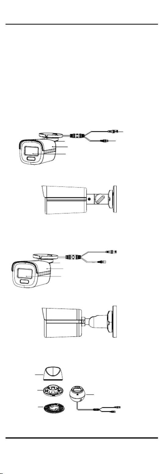
1.2 Overview
1.2.1 Overview of Type I Camera
Power Cord
Video Cable
Bracket
Main Body
Lens
Figure 1-1 Overview of Type I Camera
Figure 1-2 Side View of Type I Camera
1.2.2 Overview of Type Camera II
Power Cord
Video Cable
Bracket
Main Body
Lens
Figure 1-3 Overview of Type II Camera
Figure 1-4 Side View of Type II Camera
1.2.3 Overview of Type Camera III
Video Cable
Power Cord
Base
Installaon
Plate
Enclosure
Main Body
Figure 1-5 Overview of Type III Camera
2 Installaon
Before you start

2
Make sure that the device in the package is in good
condion and all the assembly parts are included.
Make sure that all the related equipment is power o -
during the installaon.
Check the specicaon of the products for the
installaon environment.
Check whether the power supply is matched with
your power output to avoid damage.
Make sure the wall is strong enough to withstand
three mes the weight of the camera and the mount.
If the product does not funcon properly, contact
your dealer or the nearest service center. DO NOT
disassemble the camera for repair or maintenance by
yourself.
2.1 Installaon of Type I and Type II Camera
2.1.1 Ceiling/Wall Mounng of Type I Camera Without
Juncon Box
Before you start:
Ceiling mounng and wall mounng are similar.
Following steps take ceiling mounng as an example.
Steps:
1. Paste the drill template (supplied) to the place
where you want to install the camera.
2. (Oponal) For cement ceiling, drill the screw holes
with a 5.5 mm drill and insert the supplied wall
plugs.
Screw
Hole Screw
Hole
Screw
Hole
tem pl ate
Cable
Hole
Figure 2-1 Drill Template
3. (Oponal) Drill the cable hole, when the cables are
routed through the ceiling.
4. Route and connect the power cord and video cable.
5. Align the screw holes in the bracket to the ceiling,
and secure the camera with three PA4 × 25 screws
(supplied).
Figure 2-2 Secure Camera to Ceiling
6. Power on the camera to adjust the view angle
according to the gure below.
Rotaon Position
[0° to 360°] Tilt Position
[0° to 180°]
Pan Position
[0° to 360°]
Trim Ring
Screw
Thumbscrew

3
Figure 2-3 - 3 Axis Adjustment
1). Loosen the trim ring to adjust the pan posion
[0° 360°].to
2). Loosen the thumbscrew to adjust the lt
posion [0° 180°].to
3). Loosen the screw to adjust the rotaon posion
[0° 360°].to
7. Tighten the trim ring and screws to nish the
installaon.
2.1.2 Ceiling/Wall Mounng of Type II camera Without
Juncon Box
Before you start:
Ceiling mounng and wall mounng are similar.
Following steps take ceiling mounng as an example.
Steps:
1. Paste the drill template (supplied) to the place
where you want to install the camera.
2. (Oponal) For cement ceiling, drill the screw holes
with a 5.5 mm drill and insert the supplied wall
plugs.
Screw
Hole Screw
Hole
Screw
Hole
template
Cable
Hole
Figure 2-4 Drill Template
3. (Oponal) Drill the cable hole, when the cables are
routed through the ceiling.
4. Route and connect the power cord and video cable.
5. Align the screw holes in the bracket to the ceiling,
and secure the camera with three PA4 × 25 screws
(supplied).
Figure 2-5 Secure Camera to Ceiling
6. Power on the camera to check whether the image
on the monitor is goen from the opmum angle. If
not, turn the trim ring counterclockwise to loosen it
and adjust the posions according to the gure
below.
Rotaon Position
[0° to 360°] Tilt Position
[0° to °]90
Pan Position
[0° to 360°]
Trim Ring
Figure 2-6 - 3 Axis Adjustment
7. Turn the trim ring clockwise to lock the posions.
2.1.3 Ceiling/Wall Mounng with Juncon Box
Before you start:

4
You need to purchase a juncon box in advance.
Ceiling mounng and wall mounng are similar.
Following steps take wall mounng as an example.
Steps:
1. Paste the drill template for juncon box to the place
where you want to install the camera.
2. (Oponal) For cement wall, drill the screw holes
with a 5.5 mm drill and insert the supplied wall
plugs.
Figure 2-7 Drill Template for Juncon Box
3. (Oponal) Drill the cable hole, when the cables are
routed through the wall.
4. Take apart the juncon box.
5. Align the screw holes of the camera with those on
the juncon box cover. tach the camera to the At
juncon box cover with three PM4 screws. × 10
Figure 2-8 Aach Camera to Juncon Box Cover
6. Secure the juncon box body on the wall with three
PA4 × screws (supplied).25
Figure 2-9 Secure Juncon Box on Wall
7. Route the cables through the boom cable hole or
side cable hole of the juncon box and connect the
cables.
8. Fix the juncon box cover on its body with three
PM3 × 16 L6 screws that come with the juncon
box.
Figure 2- Fix Juncon Box Cover on Its 10
Body
5
9. Refer to steps 6 to 7 of or 2.1.2 2.1.2Ceiling/Wall
Mounng of Type II camera Without Juncon Box to
adjust the view angle.
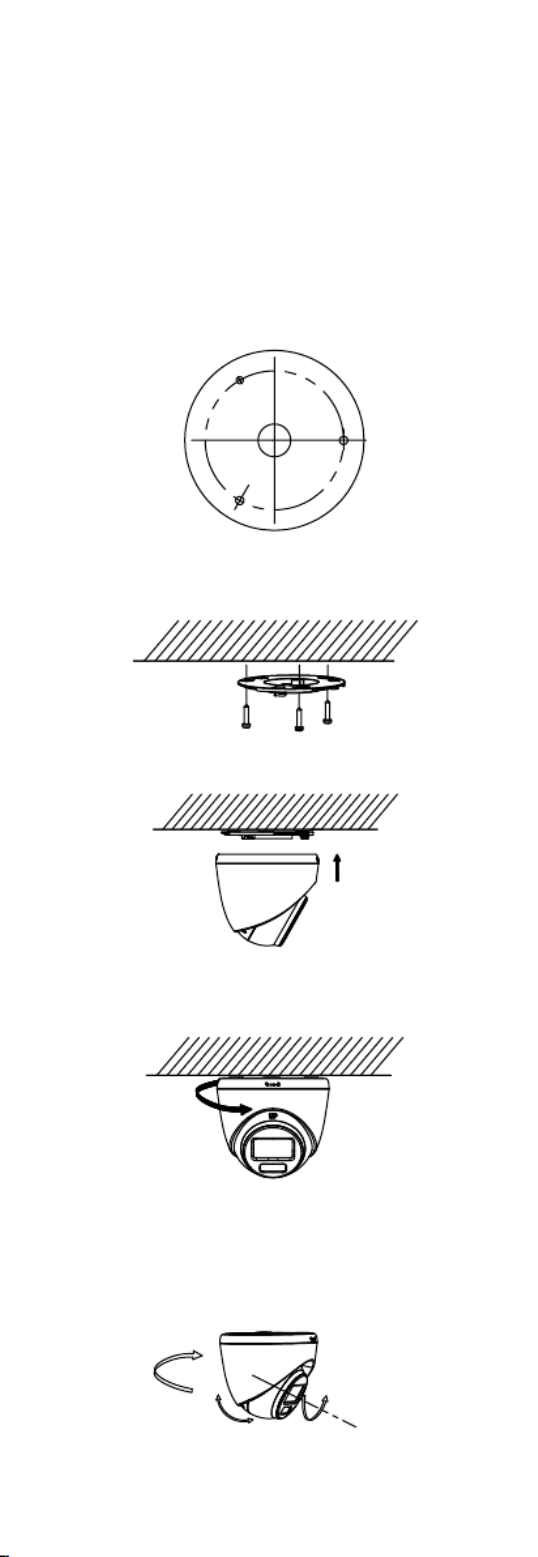
2.2 Installaon of Type Camera III
2.2.1 Ceiling Mounng without Juncon Box
Steps:
1. Paste the drill template (supplied) to the place
where you want to install the camera.
2. (Oponal) For cement ceiling, drill the screw holes
with a 5.5 mm drill and insert the supplied wall
plugs.
Figure 2-11 Drill Template
3. Aach the installaon plate to the ceiling and secure
it with three PA4 × 25 screws (supplied).
Figure 2- Aach Installaon Plate to Ceiling 12
4. Fit the camera onto the installaon plate.
Figure 2- Fit Camera 13
5. Turn the camera clockwise unl it snaps into the
installaon plate.
Figure 2- Snap Camera into Installaon Plate 14
6. Connect the power cord and video cable.
7. Power on the camera to check whether the image
on the monitor is goen from the opmum angle. If
not, adjust the camera according to the gure
below.
Rotaon Position
[0° to 360°]
Pan Position
[0° to 360°]
Tilt Position
[0° to °]75

6
Figure 2- 3-Axis Adjustment 15
1). Rotate the enclosure to adjust the pan posion
[0° 360°].to
2). Move the main body up and down to adjust the
lt posion [0° to 75°].
3). Rotate the main body to adjust the rotaon
posion [0° to 360°].
2.2.2 Ceiling Mounng with Juncon Box/Inclined
Ceiling Mount
Before you start:
You need to purchase a juncon box or inclined
ceiling mount in advance.
Ceiling mounng with juncon box and inclined
ceiling mount are similar. Following steps take
juncon box as an example.
Steps:
1. Paste the drill template for juncon box to the place
where you want to install the camera.
2. (Oponal) For cement ceiling, drill the screw holes
with a 5.5 mm drill and insert the supplied wall
plugs.
Figure 2-16 Drill Template
3. (Oponal) Drill the cable hole, when the cables are
routed through the wall.
4. Take apart the juncon box.
5. Install the installaon plate to the juncon box
cover with three PM4 screws.
Figure 2-17 Install Installaon Plate to Juncon Box
Cover
6. Fit the camera onto the installaon plate.
Figure 2- Fit Camera 18
7. Turn the camera clockwise unl it snaps into the
installaon plate.
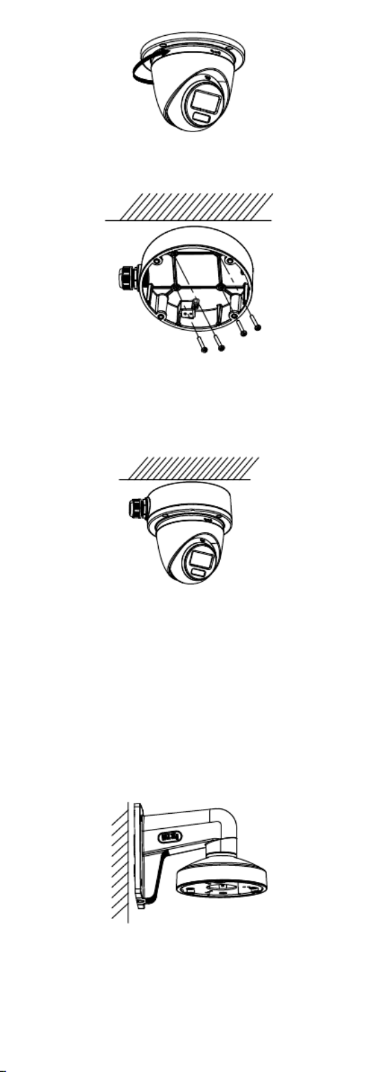
7
Figure 2- Snap Camera into Installaon Plate 19
8. Secure the juncon box body on the ceiling with
four PA4 × 25 screws.
Figure 2- Secure Juncon Box Body 20
9. Route the cables through the boom cable hole or
the side cable hole of the juncon box and connect
the cables.
10. Combine the juncon box cover with its body with
four PM4 screws.
Figure 2- Combine Juncon Box Cover with Body 21
11. Refer to step 7 of 2.2.1 Ceiling Mounng without
Juncon Box to adjust the angle.
2.2.3 Wall Mounng
Before you start:
You need to purchase a wall mount in advance.
Steps:
1. Drill Φ 10 mm screw holes in the wall where you
want to install the wall mount.
2. Use four M6 expansion bolts to x the wall mount
onto the wall.
Figure 2- Fix Wall Mount 22
3. Use three PM4 × 10 screws to x the installaon
plate onto the wall mount.

8
Figure 2- Fix Installaon Plate 23
4. Repeat the step 4 to 7 of 2.2.1 Ceiling Mounng
without Juncon Box to nish the installaon.
Figure 2- Finish Installaon 24
3 Menu Descripon
Please follow the steps below to call the menu.
Note:
The actual display may vary with your camera model.
Steps:
1. Connect the camera with the TVI DVR and the
monitor, as shown gure 3 1.in -
Camera
TVI DVR
Monitor
Figure 3-1 Connecon
2. Power on the camera, TVI DVR, and monitor to view
the image on the monitor.
3. Click PTZ Control to enter the PTZ Control interface.
4. Call the camera menu by clicking buon, clicking
Iris+, or calling preset No. 95.
Note:
Funcons may dier from models. Please take the
actual product as standard.

9
EXPOSURE
EXPOSURE MODE
MAIN MENU
VIDEO
SETTINGS
FUNCTIONS
EXIT
SAVE & EXIT
AGC
BACK
EXIT
CONTRAST
SHARPNESS
SATURATION
3 DNR
MIRROR
BACK
BACK
EXIT
VIDEO
FORMAT
FACTORY
DEFAULT
SAVE EXIT&
WHITE BALANCE
BRIGHTNESS
EXIT
SAVE EXIT &
SAVE & EXIT
IMAGE MODE
MOTION DET
PRIVACY
ANTI - BANDING
SMART
LIGHT
LIGHT
BACK
EXIT
SAVE & EXIT
THRESHOLD
LEVEL
SLOW SHUTTER
MODE
CANCEL
CONFIRM
Figure 3-2 Main Menu Overview
5. Click the direcon buons to control the camera.
1). Click up/down direcon buons to select menu
opons.
2). Click Iris + to conrm the selecon.
3). Click le/right direcon buons to adjust the
value of the selected opon.
3.1 VIDEO FORMAT
You can set the video format to 3K@ fps 4MP@25fps, 20 ,
4MP@30fps, 2MP@25fps, or 2MP@30fps .

10
3.2 EXPOSURE
EXPOSURE MODE
You can set the EXPOSURE MODE GLOBAL BLC HLC to , , ,
WDR HLS, or .
GLOBAL
GLOBAL refers to the normal exposure mode that
adjusts lighng distribuon, variaons, and
non standard processing.-
BLC (Backlight Compensaon)
BLC (Backlight Compensaon) compensates light to the
object in the front to make it clear, but this may cause
over exposure of the background where the light is -
strong.
HLC (Highlight Compensaon)
HLC stands for highlight compensaon. The camera
detects strong spots (over exposure poron of image) -
and reduces the brightness of strong spots to improve
the overall images.
WDR (Wide Dynamic Range)
The wide dynamic range (WDR) funcon helps the
camera provide clear images even under back light
circumstances. When there are both very bright and
very dark areas simultaneously in the eld of view, WDR
balances the brightness level of the whole image and
provides clear detailed images.
HLS (Highlight Suppression)
It is the same visual eect as the solar eclipse. If the
brightness of a part in the image exceeds the threshold,
this part will become black. Then whole image can be
clear.
AGC (Auto Gain Control)
It opmizes the clarity of the image in poor light
condions. The level can be set to AGC HIGH, MEDIUM,
or LOW.
Note:
The noise will be amplied when seng the level.AGC
SLOW SHUTTER
SLOW SHUTTER increases the exposure me on a single
frame, which makes a camera more sensive to the
light so it can produce images even in low lux
condions.
Note:
The funcon is not supported by the device model with
power over coaxial (PoC) technology.
ANTI-BANDING
ANTI BANDING- is a camera seng that prevents the
appearance of horizontal lines (banding) when
photographing images in low frequency light and high
brightness environments.
3.3 VIDEO SETTINGS
Move the cursor to and click Iris+ to VIDEO SETTINGS
enter the submenu. IMAGE MODE, WHITE BALANCE,
BRIGHTNESS CONTRAST SHARPNESS SATURATION,, , ,
3DNR, and are adjustable.MIRROR

11
VIDEO SETTINGS
IMAGE MODE STD
WHITE BALANCE
BRIGHTNESS
CONTRAST
SHARPNESS
SATURATION
3DNR
MIRROR
BACK
EXIT
SAVE & EXIT
5
5
5
5
5
OFF
Figure 3-3 VIDEO SETTINGS
IMAGE MODE
IMAGE MODE is used to adjust the image saturation,
and you can set it to STD (Standard), HIGH SAT- igh (H
Saturation), or (better indoor facial details).HIGHLIGHT
WHITE BALANCE
White balance, the white rendition function of the
camera, is to adjust the color temperature according to
the environment. It can remove unrealistic color casts in
the image. You can set mode to WHITE BALANCE AUTO,
OUTDOOR GLOBAL MANUAL, , or .
AUTO
The white balance can automatically adjust according to
the environment.
OUTDOOR
You can choose this mode for outdoor environment.
GLOBAL
You can choose this mode in complicated scene, such as
public square.
Note:
AWB LOCK is supported under AUTO, OUTDOOR, and
GLOBAL modes.
MANUAL
You can set the R-GAIN B GAIN/ - value to adjust the
shades of red/blue color of the image.
WHITE BALANCE
MODE
R-GAIN
B-GAIN
BA CK
EXIT
SAVE&EXIT
MANUAL
5
5
Figure 3-4 WHITE BALANCE
BRIGHTNESS
Brightness refers to the brightness of the image. You
can set the brightness value from 1 to 9 to darken or
brighten the image. The greater the value is, the
brighter the image is.
CONTRAST
This feature enhances the difference in color and light
between parts of an image.
SHARPNESS
Sharpness determines the amount of detail an imaging
system can reproduce.

12
SATURATION
Saturaon is the proporon of pure chromac color in
the total color sensaon. Adjust this feature to change
the saturaon of the color.
3DNR (3D DNR)
3DNR refers to 3D digital noise reducon. Comparing
with the general 2D digital noise reducon, the 3D
digital noise reducon funcon processes the noise
between two frames besides processing the noise in
one frame. The noise will be much less and the video
will be clearer.
MIRROR
OFF, H V, , and HV are selectable for mirror.
OFF: The mirror funcon is disabled.
H: The image ips 180 horizontally.°
V: The image ips 180° vercally.
HV: The image ips 180° both horizontally and
vercally.
3.4 SMART LIGHT
Under the sub menu, you can set the SMART LIGHT -
mode to or OFF AUTO.
OFF
Set it to to give up this funcon.OFF
AUTO
You can set THRESHOLD LEVEL and in this secon.
SMART LIG HT
LIGHT
THRESHOLD
LEVEL
MODE
BACK
EXIT
SAVE & E XIT
AUTO
2
5
MODE1
Figure 3-5 SMART LIGHT
THRESHOLD
The higher the threshold is, the more sensive the
device is to dark environment.
LEVEL
You can adjust the maximum brightness of supplement
light.
MODE
The funcon is to reduce frame rate in low light -
environment in order to increase SNR and enhance the
brightness of the image.
MODE1: Turn on the funcon.
MODE2: Turn o the funcon.
3.5 FUNCTIONS
3.5.1 MOTION DET
MOTION DET refers to moon detecon. With moon
detecon feature, moon can be detected in any part
of a camera's view. You can congure full screen or a
number of zones in a camera’s view where moon is to
be detected.

13
3.5.2 PRIVACY
This funcon allows you to block or mask certain area
of a scene to protect personal privacy from being
recorded or live viewed You can turn on/o the .
PRIVACY to meet your needs.
3.6 FACTORY DEFAULT
Reset all the sengs, except for image mode, to factory
defaults.
3.7 EXIT
Move the cursor to and click Iris+ exit the menu.EXIT to
3.8 SAVE & EXIT
Move the cursor to and click Iris+ to save SAVE & EXIT
the sengs and exit the menu.
UD22233B
Specyfikacje produktu
| Marka: | Hikvision |
| Kategoria: | Kamera monitorująca |
| Model: | DS-2CE10KF3T-E |
Potrzebujesz pomocy?
Jeśli potrzebujesz pomocy z Hikvision DS-2CE10KF3T-E, zadaj pytanie poniżej, a inni użytkownicy Ci odpowiedzą
Instrukcje Kamera monitorująca Hikvision

12 Stycznia 2025
12 Stycznia 2025
12 Stycznia 2025
12 Stycznia 2025
11 Stycznia 2025
7 Stycznia 2025
19 Grudnia 2024
19 Grudnia 2024
19 Grudnia 2024
19 Grudnia 2024
Instrukcje Kamera monitorująca
- Kamera monitorująca Sony
- Kamera monitorująca Samsung
- Kamera monitorująca Tenda
- Kamera monitorująca Motorola
- Kamera monitorująca Stabo
- Kamera monitorująca Logitech
- Kamera monitorująca Xiaomi
- Kamera monitorująca Braun
- Kamera monitorująca Pioneer
- Kamera monitorująca TP-Link
- Kamera monitorująca Philips
- Kamera monitorująca Bosch
- Kamera monitorująca Gigaset
- Kamera monitorująca EZVIZ
- Kamera monitorująca Conceptronic
- Kamera monitorująca Panasonic
- Kamera monitorująca Canon
- Kamera monitorująca Crestron
- Kamera monitorująca Withings
- Kamera monitorująca Asus
- Kamera monitorująca Nedis
- Kamera monitorująca AG Neovo
- Kamera monitorująca Reolink
- Kamera monitorująca Boss
- Kamera monitorująca TRENDnet
- Kamera monitorująca Marquant
- Kamera monitorująca Toshiba
- Kamera monitorująca D-Link
- Kamera monitorująca August
- Kamera monitorująca Niceboy
- Kamera monitorująca Ring
- Kamera monitorująca Garmin
- Kamera monitorująca Imou
- Kamera monitorująca Blaupunkt
- Kamera monitorująca Grundig
- Kamera monitorująca APC
- Kamera monitorująca Honeywell
- Kamera monitorująca BLOW
- Kamera monitorująca Manhattan
- Kamera monitorująca Strong
- Kamera monitorująca Swann
- Kamera monitorująca Kwikset
- Kamera monitorująca Kodak
- Kamera monitorująca Cisco
- Kamera monitorująca ORNO
- Kamera monitorująca Broan
- Kamera monitorująca Moxa
- Kamera monitorująca Synology
- Kamera monitorująca Gembird
- Kamera monitorująca ZTE
- Kamera monitorująca Turing
- Kamera monitorująca Lindy
- Kamera monitorująca Minox
- Kamera monitorująca Zebra
- Kamera monitorująca DSC
- Kamera monitorująca JVC
- Kamera monitorująca ZyXEL
- Kamera monitorująca Trust
- Kamera monitorująca LogiLink
- Kamera monitorująca Furrion
- Kamera monitorująca Linksys
- Kamera monitorująca Google
- Kamera monitorująca Digitus
- Kamera monitorująca Vimar
- Kamera monitorująca V-TAC
- Kamera monitorująca Dahua Technology
- Kamera monitorująca Schneider
- Kamera monitorująca Eufy
- Kamera monitorująca Ricoh
- Kamera monitorująca Emos
- Kamera monitorująca AVMATRIX
- Kamera monitorująca Renkforce
- Kamera monitorująca Rollei
- Kamera monitorująca Marshall
- Kamera monitorująca Perel
- Kamera monitorująca Somfy
- Kamera monitorująca Uniden
- Kamera monitorująca Netgear
- Kamera monitorująca Thomson
- Kamera monitorująca DiO
- Kamera monitorująca Velleman
- Kamera monitorująca Ferguson
- Kamera monitorująca DataVideo
- Kamera monitorująca Delta Dore
- Kamera monitorująca Pyle
- Kamera monitorująca Intellinet
- Kamera monitorująca CRUX
- Kamera monitorująca Setti+
- Kamera monitorująca Waeco
- Kamera monitorująca Vivotek
- Kamera monitorująca Vtech
- Kamera monitorująca Speco Technologies
- Kamera monitorująca EtiamPro
- Kamera monitorująca Edimax
- Kamera monitorująca Petcube
- Kamera monitorująca ION
- Kamera monitorująca First Alert
- Kamera monitorująca AirLive
- Kamera monitorująca Maginon
- Kamera monitorująca EnGenius
- Kamera monitorująca SPC
- Kamera monitorująca Planet
- Kamera monitorująca Brilliant
- Kamera monitorująca Genie
- Kamera monitorująca LevelOne
- Kamera monitorująca Axis
- Kamera monitorująca Sanyo
- Kamera monitorująca Lorex
- Kamera monitorująca Control4
- Kamera monitorująca Milesight
- Kamera monitorująca Aluratek
- Kamera monitorująca Abus
- Kamera monitorująca Elro
- Kamera monitorująca Olympia
- Kamera monitorująca Hama
- Kamera monitorująca Marmitek
- Kamera monitorująca Ubiquiti Networks
- Kamera monitorująca Western Digital
- Kamera monitorująca Netatmo
- Kamera monitorująca Schwaiger
- Kamera monitorująca Promise Technology
- Kamera monitorująca GVI Security
- Kamera monitorująca AVer
- Kamera monitorująca ZKTeco
- Kamera monitorująca Netis
- Kamera monitorująca Extech
- Kamera monitorująca Denver
- Kamera monitorująca Anker
- Kamera monitorująca Allnet
- Kamera monitorująca Marshall Electronics
- Kamera monitorująca Orion
- Kamera monitorująca Yale
- Kamera monitorująca SereneLife
- Kamera monitorująca Ernitec
- Kamera monitorująca AVerMedia
- Kamera monitorująca MEE Audio
- Kamera monitorująca Genius
- Kamera monitorująca Trevi
- Kamera monitorująca Technaxx
- Kamera monitorująca Atlona
- Kamera monitorująca Hanwha
- Kamera monitorująca Overmax
- Kamera monitorująca Quantum
- Kamera monitorująca Y-cam
- Kamera monitorująca Grandstream
- Kamera monitorująca Raymarine
- Kamera monitorująca Powerfix
- Kamera monitorująca Avanti
- Kamera monitorująca Ikan
- Kamera monitorująca Alecto
- Kamera monitorująca Avidsen
- Kamera monitorująca JUNG
- Kamera monitorująca Burg Wächter
- Kamera monitorująca Foscam
- Kamera monitorująca Lumens
- Kamera monitorująca Monacor
- Kamera monitorująca Dörr
- Kamera monitorująca M-e
- Kamera monitorująca EVE
- Kamera monitorująca Smartwares
- Kamera monitorująca Adj
- Kamera monitorująca Qian
- Kamera monitorująca Arenti
- Kamera monitorująca Elmo
- Kamera monitorująca Vitek
- Kamera monitorująca Alfatron
- Kamera monitorująca UniView
- Kamera monitorująca Clas Ohlson
- Kamera monitorująca Laserliner
- Kamera monitorująca Megasat
- Kamera monitorująca REVO
- Kamera monitorująca BZBGear
- Kamera monitorująca BirdDog
- Kamera monitorująca KJB Security Products
- Kamera monitorująca HiLook
- Kamera monitorująca Profile
- Kamera monitorująca Aldi
- Kamera monitorująca Aritech
- Kamera monitorująca Acti
- Kamera monitorująca ACME
- Kamera monitorująca Flamingo
- Kamera monitorująca Caliber
- Kamera monitorująca Eminent
- Kamera monitorująca Sitecom
- Kamera monitorująca Exibel
- Kamera monitorująca Fortinet
- Kamera monitorująca KlikaanKlikuit
- Kamera monitorująca Trebs
- Kamera monitorująca Ednet
- Kamera monitorująca Steren
- Kamera monitorująca Flir
- Kamera monitorująca Buffalo
- Kamera monitorująca Arlo
- Kamera monitorująca Nest
- Kamera monitorująca Siedle
- Kamera monitorująca Hive
- Kamera monitorująca Switel
- Kamera monitorująca Chacon
- Kamera monitorująca InFocus
- Kamera monitorująca Hombli
- Kamera monitorująca Naxa
- Kamera monitorująca Konig
- Kamera monitorująca Valueline
- Kamera monitorująca BRK
- Kamera monitorująca QSC
- Kamera monitorująca Xavax
- Kamera monitorująca Vaddio
- Kamera monitorująca Gira
- Kamera monitorująca Interlogix
- Kamera monitorująca Boyo
- Kamera monitorująca IC Intracom
- Kamera monitorująca Iget
- Kamera monitorująca EverFocus
- Kamera monitorująca Adesso
- Kamera monitorująca Satel
- Kamera monitorująca POSline
- Kamera monitorująca Notifier
- Kamera monitorująca Hawking Technologies
- Kamera monitorująca Friedland
- Kamera monitorująca Nexxt
- Kamera monitorująca Monoprice
- Kamera monitorująca Watec
- Kamera monitorująca Beafon
- Kamera monitorująca Chuango
- Kamera monitorująca ETiger
- Kamera monitorująca Videcon
- Kamera monitorująca INSTAR
- Kamera monitorująca Provision ISR
- Kamera monitorująca Aqara
- Kamera monitorująca Advantech
- Kamera monitorująca Digital Watchdog
- Kamera monitorująca Ganz
- Kamera monitorująca AViPAS
- Kamera monitorująca ClearOne
- Kamera monitorująca Ebode
- Kamera monitorująca Oplink
- Kamera monitorująca Sonic Alert
- Kamera monitorująca Linear PRO Access
- Kamera monitorująca Summer Infant
- Kamera monitorująca SMC
- Kamera monitorująca Topica
- Kamera monitorująca Kogan
- Kamera monitorująca Iiquu
- Kamera monitorująca Verint
- Kamera monitorująca Brinno
- Kamera monitorująca Rostra
- Kamera monitorująca Caddx
- Kamera monitorująca Spyclops
- Kamera monitorująca EKO
- Kamera monitorująca Kguard
- Kamera monitorująca Woonveilig
- Kamera monitorująca Mobi
- Kamera monitorująca Surveon
- Kamera monitorująca Hollyland
- Kamera monitorująca Epcom
- Kamera monitorująca Indexa
- Kamera monitorująca Lutec
- Kamera monitorująca Whistler
- Kamera monitorująca ClearView
- Kamera monitorująca VideoComm
- Kamera monitorująca IMILAB
- Kamera monitorująca 3xLOGIC
- Kamera monitorująca Pelco
- Kamera monitorująca Leviton
- Kamera monitorująca Inkovideo
- Kamera monitorująca Pentatech
- Kamera monitorująca Weldex
- Kamera monitorująca SecurityMan
- Kamera monitorująca Canyon
- Kamera monitorująca CNB Technology
- Kamera monitorująca Tapo
- Kamera monitorująca Aigis
- Kamera monitorująca Exacq
- Kamera monitorująca Brickcom
- Kamera monitorująca Laxihub
- Kamera monitorująca Securetech
- Kamera monitorująca EFB Elektronik
- Kamera monitorująca NetMedia
- Kamera monitorująca Videotec
- Kamera monitorująca Illustra
- Kamera monitorująca Nivian
- Kamera monitorująca E-bench
- Kamera monitorująca Syscom
- Kamera monitorująca Tecno
- Kamera monitorująca Night Owl
- Kamera monitorująca Guardzilla
- Kamera monitorująca Astak
- Kamera monitorująca Blink
- Kamera monitorująca Milestone Systems
- Kamera monitorująca Zavio
- Kamera monitorująca Campark
- Kamera monitorująca IPX
- Kamera monitorująca Dedicated Micros
- Kamera monitorująca Hamlet
- Kamera monitorująca Annke
- Kamera monitorująca AVTech
- Kamera monitorująca Qoltec
- Kamera monitorująca Approx
- Kamera monitorująca Digimerge
- Kamera monitorująca Wisenet
- Kamera monitorująca Infortrend
- Kamera monitorująca Epiphan
- Kamera monitorująca Mach Power
- Kamera monitorująca Compro
- Kamera monitorująca Aida
- Kamera monitorująca Ikegami
- Kamera monitorująca Accsoon
- Kamera monitorująca Vimtag
- Kamera monitorująca Gewiss
- Kamera monitorująca Alula
- Kamera monitorująca Insteon
- Kamera monitorująca Costar
- Kamera monitorująca ALC
- Kamera monitorująca Security Labs
- Kamera monitorująca Comtrend
- Kamera monitorująca Seneca
- Kamera monitorująca Avigilon
- Kamera monitorująca American Dynamics
- Kamera monitorująca Vosker
- Kamera monitorująca Sentry360
- Kamera monitorująca Bea-fon
- Kamera monitorująca Owltron
- Kamera monitorująca Enabot
- Kamera monitorująca Luis Energy
- Kamera monitorująca Sir Gawain
- Kamera monitorująca VisorTech
- Kamera monitorująca Atlantis Land
- Kamera monitorująca B & S Technology
- Kamera monitorująca I3International
- Kamera monitorująca IDIS
- Kamera monitorująca Ecobee
- Kamera monitorująca Conbrov
- Kamera monitorująca HuddleCamHD
- Kamera monitorująca Mobotix
- Kamera monitorująca IOIO
- Kamera monitorująca BIRDFY
- Kamera monitorująca I-PRO
- Kamera monitorująca DVDO
- Kamera monitorująca TCP
- Kamera monitorująca Bolin Technology
- Kamera monitorująca Nextech
Najnowsze instrukcje dla Kamera monitorująca

28 Stycznia 2025
25 Stycznia 2025
17 Stycznia 2025
15 Stycznia 2025

13 Stycznia 2025

13 Stycznia 2025
13 Stycznia 2025
12 Stycznia 2025
12 Stycznia 2025
12 Stycznia 2025